SYSTEM KAN-therm Push Platinum ISO 9001
|
|
|
- Beverly Wilson
- 5 years ago
- Views:
Transcription


1 SYSTEM KAN-therm Push Platinum ISO 9001
2 Contents Page System KAN-therm Push Platinum - General information...3 System KAN-therm Push Platinum - Technical information...4 Multi-layer PE-Xc/Al/PE-HD Platinum pipes...5 Parameters of multi-layer PE-Xc/Al/PE-HD Platinum pipes...5 Multi-layer PE-Xc/Al/PE-HD Platinum pipes Physical properties...6 Transport and storage...6 Push Platinum connections...6 Fittings for the KAN-therm Push Platinum System connections...7 Brass sleevs for KAN-therm Push Platinum System joints...7 Assembling Push Platinum joints...8 Tools for Push Platinum joints...11 Heads for Push Platinum joints...11 Tools - Safety...11 Screwed connections for PE-Xc/Al/PE-HD Platinum pipes Compression fittings for PE-Xc/Al/PE-HD Platinum pipes mm Joining fittings with nickel-plated pipes with radiator fixtures Union connection for PE-Xc/Al/PE-HD Platinum pipes System KAN-therm Push Platinum Compensation of thermal elongation System KAN-therm Push - Technical information PE-RT pipes PE-Xc pipes PE-RT and PE-Xc pipes operating parameters PE-RT and PE-Xc pipes: Physical properties Transport and storage Contact with substances containing solvents, sealing the threads Push connections Assembly of Push connections...20 Tools for Push connections...24 Tools - Safety...24 Screwed joints for PE-RT and PE-Xc - Ø12-32 mm...25 Eurocone adapters for PE-RT and PE-Xc - Ø12-25 mm pipes...26 Joining fittings with nickel-plated pipes with radiator fixtures...26 System KAN-therm Push/Push Platinum...27 System KAN-therm Push - diameter 18 x 2,0 - available till System KAN-therm Push - screwed connections for PE-Xc & PE-RT pipes System KAN-therm Push - tools for Push connections...45 This commercial information is binding as of June 1st, From the date this information is published information concerning same matter is no longer in force. KAN Sp. z o.o. reserves the right to complement this information, to change it or replace it by any other commercial information at any time. Copyright KAN Sp. z o.o. All rights reserved. The text, graphics, and the graphical outlay in KAN Sp. z o. o. publications are protected by copyright.
3 System KAN-therm Push Platinum - General information This catalogue of the KAN-therm Push System includes a new KAN-therm Push Platinum System and the standard KAN-therm Push System. The catalogue is divided into a Technical Part and an Assortment Part: KAN-therm Push Platinum System Technical Part, KAN-therm Push Platinum System Technical Part, KAN-therm Push Platinum System and KAN-therm Push System common part. The technical part includes all information required to order products and for its assembly on a construction site etc. For more details please see KAN-therm System Designers and Contractors Guide. The common assortment part of the catalogue comprises: 1. The KAN-therm Push Platinum System used for water supply systems and heating systems and comprising: PE-Xc/Al/PE-HD Platinum multi-layer pipes within the range of mm diameters, PPSU plastic fittings and brass fittings for PE-Xc, PE-RT and PE-Xc/Al/PE-HD Platinum pipes. 2. The KAN-therm Push System used for water supply systems and heating systems and comprising two material configurations of pipes and fittings: PE-Xc pipes with an anti-diffusion barrier within a range of diameters mm, PE-RT pipes with an anti-diffusion barrier within a range of diameters mm, PPSU plastic fittings and brass fittings for PE-Xc, PE-RT and PE-Xc/Al/PE-HD Platinum pipes. 3. Push System fittings dia (available till January ) Since KAN-therm Push System plastic PPSU fittings and brass fittings for PE-Xc and PE-RT - dia. 18x2 pipes, are successively withdrawn from the offer nonetheless here all the KAN-therm Push elements available till are listed. 4. Screwed joints for mm dia. PE-Xc and PE-RT pipes. 5. Tools for assembling KAN-therm Push System pipes and fittings. CAUTION!!! PE-Xc and PE-RT pipes with the anti-diffusion barrier in diameters 16 2 and 18 2 designed mainly for floor heating and manifold-based heating systems are available in the catalogue KAN-therm System: Screwed joints and KAN-therm System Underfloor heating


4 System KAN-therm Push Platinum - Technical information The KAN-therm Push Platinum System is a modern and complete system consisting of multi-layer PE- Xc/Al/PE-HD Platinum pipes and standard KAN-therm Push fittings made of PPSU or brass, within a diameter range of mm. Push Platinum System leak-tight joints without O-Rings are made by pushing a brass sleeve onto a fitting and a pipe. These connections do not require additional sealing like a PTFE tape or tow. The system is complemented by manifolds and installation cabinets available in section Manifolds, cabinets and accessories. The latest plastic material invention PPSU phenylene polysulfone used for fittings production ensures: full resistance against corrosion, full neutratrality against potable water, durability of fittings higher than that of pipes, high mechanical strength. The technology of making PPSU fittings practically excludes possible occurence of hidden defects. Due to a perfect design of parts of the KAN-therm Push Platinum System and their mutual matching, provides: over a 50-years opration lifetime, high temperature operation T work = 80 C (operating temperature), T max = 90 C (max. temperature the heat source must be protected against a temperature rise above that level), extremely durable PPSU joints with the max. operating temperatures limted by the pipe life, absolutely no corrosion irrespective of the water quality, The KAN-therm Push Platinum System allows for a selection of best solutions both in technical and cost terms as: joints can be hidden in screed and under plaster, possibility of connecting with systems made of other materials, possible cost-saving distribution systems. The KAN-therm Push Platinum System guarantees full safety of mounting and operation. PPSU fittings are made according to PN-EN ISO :2005 and PN-EN ISO :2010, and obtains hygiene certyficates by PZH, brass Push type fittings conform to PN-EN :2004, and obtains hygiene certyficates by PZH, multi-layer PE-Xc/Al/PE-HD Platinum pipes conform to PN-EN ISO and obtains hygiene certyficates by PZH
5 System KAN-therm Push Platinum - Technical information Multi-layer PE-Xc/Al/PE-HD Platinum pipes PE-Xc/Al/PE-HD Platinum pipes are manufactured as multi-layer pipes, where the base-pipe is made of the PE-Xc polyethylene subjected to molecular crosslinking by an electron beam. Laser-welded aluminium layer provides a complete protection against oxygen diffusion and significantly lowers the thermal expansion of a pipe. An external coating of the highdensity polyethylene PH-ED protects the aluminium layer against a mechanical damage. Due to their design, pipes do not have the shape memory and can be given any shape. Assortment of PE-Xc/Al/PE-HD Platinum pipes: PE-Xc/Al/PE-HD Platinum multi-layer pipes according to PN-EN ISO standard in dia. 14, 18, 25, 32 mm. Dimensions, application and water volumes of multi-layer PE-Xc/Al/PE-HD Platinum pipes: Rated diameter DN OD [mm] Wall thickness [mm] For installation: Water volume [dm³/m] ,25 c.h. / t. c.w. & h.w. 0, ,8 c.h. / t. c.w. & h.w 0, ,7 c.h. / t. c.w. & h.w 0, ,7 c.h. / t. c.w. & h.w 0,401 Parameters of multi-layer PE-Xc/Al/PE-HD Platinum pipes Operating parameters of multi-layer PE-Xc/Al/PE-HD Platinum pipes acc. to PN-EN ISO : Installation and application class (acc. to ISO 10508) tap cold water tap hot water (class 1) tap hot water (class 2) underfloor heating, radiator heating low temperature (class 4) radiator heating (class 5) Nominal dia. DN External diameter [mm] Wall thickness [mm] Operating parameters P work [bar] T work /T max [ C] Push (with sliding sleeve) Connection type Screwed (threaded) , , , , , / , / , / , / , / , / , / , / , / , / , / , / , / , / , / , / Operating temperature T work for individual classes shall be regarded as a design temperature, the maximal temp. - T max - as a temperature, which should not be exceeded the system must be protected against it
![System KAN-therm Push Platinum - Technical information Multi-layer PE-Xc/Al/PE-HD Platinum pipes Physical properties Property Unit Value 1 Heat conductivity [W/mK] 0,4 2 Coefficient of linear](/docs-images/96/128961230/images/6-0.jpg "expansion [mm/mk] 0,025 3 Material constant 33 4 Material density [g/cm³] 0,95 5 Internal pipe roughness (absolute) [mm] 0,007 6 Max temperature [ C] 95 7 E module [N/mm2] 2950 8 without bending")
6 System KAN-therm Push Platinum - Technical information Multi-layer PE-Xc/Al/PE-HD Platinum pipes Physical properties Property Unit Value 1 Heat conductivity [W/mK] 0,4 2 Coefficient of linear expansion [mm/mk] 0,025 3 Material constant 33 4 Material density [g/cm³] 0,95 5 Internal pipe roughness (absolute) [mm] 0,007 6 Max temperature [ C] 95 7 E module [N/mm2] without bending spring 5 x Dz Minimum bending radius with bending spring 3 x Dz 1000 ( 14-18) 9 Max distance between supports [mm] 1500 ( 25-32) Transport and storage Multilayer PE-Xc/Al/PE-HD Platinum pipes are delivered in 25, 50, 200 m coils in carton packages. They can be stored in different temperatures,also below 0 C. Due to vulnerability to UV rays, pipes should be protected against direct, long-lasting exposure to sunlight. Contact with substances containing solvents, sealing the threads. Avoid direct contact of KAN-therm elements with solvents or solvent-containing materials, such as paints, aerosols, montage foams, adhesives, etc. Under unfavorable circumstances, these substances may damage plastic parts. Make sure that the connection sealants, cleaners or insulation of System KAN-therm components, do not contain compounds that cause stress cracks: ammonia, ammonia retaining compounds, solvents, aromatic or chlorinated hydrocarbons (e.g., ketones and ethers). Do not use montage foams based on methacrylate and acrylate isocyanate. For the threaded connections it is recommended to use hemp in an amount such that the tops of the thread are still visible. Using too much hemp may damage the thread. Winding hemp just after first turn of the thread helps to avoid diagonal screwing and thread damage. Caution! Do not use chemical sealants and adhesives. Push Platinum connections Perfoming Push Platinum connection consist in sliding brass sleeve over the pipe and fitting with hand operated, hydraulic or electric machine. 1 KAN-therm Push System fitting (PPSU tee) KAN-therm Push System brass sleeve 2 3 Multi-layer PE-Xc/Al/PE-HD Platinum pipe - 6 -
7 System KAN-therm Push Platinum - Technical information Fittings for the KAN-therm Push Platinum System connections To perform connections with the KAN-therm Push Platinum pipes, standard KAN-therm Push PPSU System fittings and brass fittings are used. elbows and tees elbows, tees and other fittings with nickel-plated Ø15mm copper pipes, couplings, Platinum eurocone adapters, male and female connectors, wallplate elbows, other. Notice: When assembling PPSU fittings keep elements clean and avoid contact with chemical agents. Brass sleevs for KAN-therm Push Platinum System joints To seal KAN-therm Push Platinum System connection of a pipe and a fitting, standard KAN-therm Push brass sleeves in diameters mm are used. Sleeve for Push connections - 7 -


8 System KAN-therm Push Platinum - Technical information Assembling Push Platinum joints 1 2 Cut a multi-layer PE-Xc/Al/PE-HD Platinum pipe to a required length with scissors. The cut must be perpendicular to the pipe axis. CAUTION!!! - For cutting use only sharp blades. Put the sleeve onto a pipe with the internally chamfered end toward a fitting. Select the sleeve properly to the pipe diameter. 3 4 Expand the pipe with a hand or electric expanding tool. In both cases use the Insert the fitting into a pipe up to the last bead on the fitting. expanding tool in three stages. First two expansions not full, with rotation of expanding tool 30 and 15 against the pipe. The third expansion is full. CAUTION!!!: For expanding use only Push Platinum expanding head - 8 -


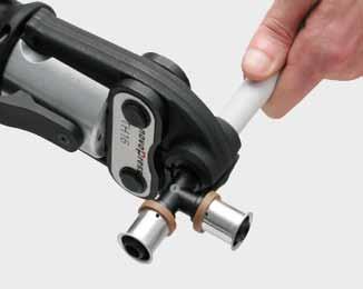
9 System KAN-therm Push Platinum - Technical information 5 6 Slide the sleeve with a hand/hydraulic or electric machine Grip fittings only at their flange. Do not slide two sleeves at the same time. Observe assembling process - after sliding the sleeve up to fittnigs flange, the whole process should be stopped. The connection is ready for pressure test. To eliminate the excessive overload on fittings by bending force, it is not recommended to bend pipes at a distance less than 10 external diameters from the fitting. Notice: 1. For assembly of a PPSU fittings use only at the side of a fitting black inserts marked T (14, 18 or 25), and at the sleeve side straight nickel-plated inserts. The PPSU fitting shall be supported at its flange directly next to the stub pipe onto which the sleeve is being pushed. nickel-plated insert straight black insert 2. When assembling a PPSU fitting dia. 32 mm insert at the fitting end, use a straight nickel-plated insert. dia. 25 mm, and on the sleeve side empty machines fork. machine fork straight nickel-plated insert Ø25mm - 9 -
.")

 and elements of connections to radiators use straight")
10 System KAN-therm Push Platinum - Technical information 3. For assembly of brass elements use straight nickel-plated inserts. nickel-plated straight insert 4. For screwed connections Ø 32 mm use only forks (no inserts). Assembling a Ø32 joint without using inserts 5. For assembly of other brass elements e.g. screwed couplings, wallplate elbows (excluding angle wallplate elbows) and elements of connections to radiators use straight nickel-plated inserts marked: P8471, P8469, P8468, P For brass tees Ø14, 18, 25 mm use at the side of fitting nickel-plated shaped inserts marked respectively P8465, P8463, P8468, and P8464. At the sleeve side use straight nickel-plated inserts. straight nickel-plated insert e.g. for Ø18mm, P8468 shaped nickel-plated insert e.g. for dia. P

 Correct way of mounting inserts on machine forks Diameter range 14-25 mm. Incorrect way of mounting inserts on machine forks Diameter range 14-25 mm.")
11 System KAN-therm Push Platinum - Technical information 7. For brass angle wallplate elbows Ø18 mm use at the fitting side shaped nickel-plated insert marked P8470. At the sleeve side use a straight nickel-plated insert. straight nickel-plated insert e.g. for Ø18mm, P8468 shaped nickel-plated insert e.g. for dia. P8470 CAUTION!!! - the presented above shaped inserts for brass joints are not a standard part of tool kits, please order them separately. Novopress tool (battery driven) Correct way of mounting inserts on machine forks Diameter range mm. Incorrect way of mounting inserts on machine forks Diameter range mm. Tools for Push Platinum joints To make a joint in the KAN-therm Push Platinum System use KAN-therm Push System tools.tools must be provided with expanding heads for multi-layer PE-Xc/Al/PE-HD Platinum pipes. There is possibility to order KPPR-PLAT tool set with Platinum expanding heads. Heads for Push Platinum joints For connections of the KAN-therm Push Platinum System use standard set of tools additionally equipped with Push Platinum heads. 1. Push Platinum expanding heads -14, 18, 25, 32 (1 piece each) Tools - Safety All tools must be applied and used in accordance with their purpose and the manufacturer s instructions. Use for other purposes or in other areas are considered to be inconsistent with the intended use. Intended use also requires compliance with the instructions, conditions of inspection and maintenance and relevant safety regulations in their current version. All works done with tools, which do not meet the application compatible with the intendedpurpose may result in damage to tools, accessories and pipes. The consequence may be the leak and / or damage

12 System KAN-therm Push Platinum - Technical information Screwed connections for PE-Xc/Al/PE-HD Platinum pipes Screwed connections in System KAN-therm Push Platinum may be carried out by: Compression fittings for PE-Xc/Al/PE-HD Platinum pipes Eurocone adapters for PE-Xc/Al/PE-HD Platinum pipes Compression fittings for PE-Xc/Al/PE-HD Platinum pipes mm. Assembling of a screwed joint: 1. Screw the joint body into a fitting provided with a sealed thread. 2. Fit the nut and the compression ring on a pipe. 3. Push a pipe onto the coupling body and screw on a ring-clamping nut. Connector body with EPDM O-ring 2 Clamping nut 4 1 Fitting female thread tee 3 Clamping ring 5 PE-Xc/Al./PE-HD Platinum pipe Fit a compression ring onto a pipe so that the ring edge is 0,5-1 mm away from the pipe edge. A pipe should be pushed to the end of the pipe connectors body. This connection may be taken apart - after the connector body is pulled out of a pipe you should cut away the used pipe end and you may create a new connection. Do not turn a fitting on a pipe during assembly and after it and do not use any lubricants to push a pipe easier onto a fitting body. Screwed joints can be combined with: female threaded fittings like elbows, tees, wallplate elbows, manifolds without a nipple, female thread fixtures. Seal these connections with tow and a paste additive but in case of brass female threads do not use too much tow, do not combine female thread (cylindrical profile) brass couplings with male pipe threads (conical profile) as brass can crack, observe the rule that female thread pipe connectors and fittings should not be combined with element other than KAN-therm System pieces,

13 System KAN-therm Push Platinum - Technical information KAN-therm brass male thread connector Female steel connector do not embed them in a floor. Union connection for PE-Xc/Al/PE-HD Platinum pipes Union connectors in the KAN-therm Push Platinum System are the only permissible form of union connections. The range of diameters for the KAN-therm Push Platinum System is mm. Platinum straight female connector (body). Clamping nut 2 4 Tee with a male thread 1 3 Compression ring. 5 PE-Xc/Al/PE-HD Platinum pipe Push Platinum screwed joints (with a white O-Ring) for Eurokonus connections can be combined with: fittings for screwed joints with a male thread (series of fittings 9012), manifolds equipped with special nipples, combined radiator valves. This kind of joints is self-sealing and no additional sealing like PTFE tape or tow should be used. Connections must be easily accessible. Joining fittings with nickel-plated pipes with radiator fixtures For good looks of a KAN-therm radiator connection both from a floor or a wall we offer special fittings with nickel-plated copper pipes. Connect fixed elbows and tees with a nickel-plated pipe with radiator valves or directly with VK-type radiators via elements like: screwed joint for a copper pipe Ø15 G¾, code , screwed joint for a copper pipe Ø15 G½, code K , clamp for a copper pipe Ø15 G½, code W, coupling body G½, code All joints of this kind are self-sealing and no additional sealing is needed
14 System KAN-therm Push Platinum - Technical information System KAN-therm Push Platinum Compensation of thermal elongation The elongation ( L) due to temperature change can be determined from the following formula: where: α - coefficient of linear expansion [mm/mk] L - length of pipeline section [m] ΔT - temperature difference (assembly and operation) [K] ΔL = α L ΔT Required length of an flexible arm is determined from the formula: where: K - material constant Dz - external diameter [mm] Ls - length of the elastic arm [mm] In case a system is embedded within diameters mm, we suggest to lay pipes in tight curves for selfcompensation of the pipelines thermal elongation
15 System KAN-therm Push General information The KAN-therm Push System is a complete system consisting of PE pipes PE-Xc or PE-RT and PPSU fittings or brass fittings within a diameter range Ø12-32 mm. A KAN-therm Push System leak-tight joints without O-Rings are made by pushing a brass sleeve onto a fitting and a pipe. These joints do not require additional sealing like a PTFE tape or tow. Other complementing elements of the system are manifolds and installation cabinets. The KAN-therm Push System was designed on a rule fast assembly permanent effect thus investment and finishing work can be substantially speed up. System KAN-therm Push Modern technology The latest plastic material invention PPSU phenylene polysulfone used for joints ensures: full resistance against corrosion, full neutrality against potable water, durability of fittings higher than that of pipes, high mechanical strength, The technology of making PPSU fittings practically excludes possible occurrence of hidden defects. System KAN-therm Push Technology for many years Due to a perfect design of parts of the KAN-therm Push System and their matching merits as follows are achieved: over a 50-year operation life, possible work at high temperatures T work. = 80 C (operating temperature), T max = 90 C (max. temperature the heat source must be protected against a temperature rise above that level), extremely durable PPSU fittings the max. operating parameters are limited by the pipe life, absolutely no corrosion irrespective of the water quality. System KAN-therm Push Optimum technology The KAN-therm Push System allows for a selection of best solutions both in technical terms and cost terms as: Push joints can be hidden in floors, possible connecting with systems made of other materials, possible cost-saving distribution systems. System KAN-therm Push Safe technology The KAN-therm Push System guarantees full safety of mounting and operation: Push type fittings made of PPSU conform to PN-EN ISO :2005 and PN-EN ISO :2010 and obtains hygiene certyficates by PZH, PE-RT pipes conform to PN-EN ISO :2010 and obtains hygiene certyficates by PZH, PE-Xc pipes conform to PN-EN ISO :2005 and obtains hygiene certyficates by PZH the abovementioned documents are binding for insulated PE-Xc and PE-RT pipes. The thermal insulation obtains the technical approval by ITB, a 10-year guarantee for the Push system
16 System KAN-therm Push Technical information PE-RT pipes PE-RT pipes of the KAN-therm Push System are made of a high thermal resistance polyethylene DOWLEX 2388 E. Assortment of PE-RT pipes: PE-RT pipes acc. to DIN 16776, 16833, 4726 pipes with an anti-diffusion barrier EVOH, series: Ø12 2; Ø14 2; Ø18 2*; Ø18 2,5; Ø25 3,5; Ø32 4,4 do for central heating systems and hot and cold tap water systems, PE-RT pipes with an anti-diffusion barrier within diameters 14 2 and 18 2*, 18 2,5 are available also in a 6 mm thick thermal insulation. KAN-therm Push pipes: dimensions, application and water volumes: OD [mm] Wall thickness [mm] EVOH shield For installation: Water volume [dm³/m] ,0 yes c.h. / t. c.w. & h.w. 0, ,0 yes c.h. / t. c.w. & h.w. 0, * 2,0 yes c.h. / t. c.w. & h.w. 0, ,5 yes c.h. / t. c.w. & h.w. 0, ,5 yes c.h. / t. c.w. & h.w. 0, ,4 yes c.h. / t. c.w. & h.w. 0,423 The EVOH (ethylene-vinyl alcohol) coating is applied directly on the base pipe and bound with it with a layer of glue. This coating satisfies the DIN 4726 requirements. PE-Xc pipes KAN-therm Push System PE-Xc pipes are manufactured form a high-density polyethylene and are subjected to cross-linking with an electron beam ( c a physical method, without using chemical agents). Assortment of PE-Xc pipes: PE-Xc pipes acc. to DIN 16892/93, 4726/29 with the EVOH anti-diffusion barrier, series Ø12 2; Ø14 2; Ø18 2*; Ø18 2,5; Ø25 3,5; Ø32 4,4 for central heating and hot and cold tap water systems, PE-Xc pipes with an anti-diffusion barrier within diameters 14 2 and 18 2*, 18 2,5 are available also in a 6 mm thick thermal insulation. KAN-therm Push System PE-Xc pipes: application and water volumes: OD [mm] wall thickness [mm] EVOH coating installation water volume [dm³/m] ,0 yes c.h. / t. c.w. & h.w. 0, ,0 yes c.h. / t. c.w. & h.w. 0, * 2,0 yes c.h. / t. c.w. & h.w. 0, ,5 yes c.h. / t. c.w. & h.w. 0, ,5 yes c.h. / t. c.w. & h.w. 0, ,4 yes c.h. / t. c.w. & h.w. 0,423 The EVOH (ethylene-vinyl alcohol) coating is applied directly on the base pipe and bound with it with a layer of glue. This coating satisfies the DIN 4726 requirements * System KAN-therm Push 18 2 connectors are offered till
17 System KAN-therm Push Technical information PE-RT and PE-Xc pipes operating parameters PE-RT pipes acc. to PN-EN ISO :2010 and PE-Xc pipes acc. to PN-EN ISO :2004: Operating parameters: Installation and application class (acc. to ISO 10508) cold tap water hot tap water (class 1) hot tap water (class 2) underfloor heating, low temperature radiator heating (class 4) radiator heating (class 5) Nominal diameter [mm]] Wall thickness [mm] EVOH coating PE-Xc Operating parameters P work [bar] PE-RT Connection type T work /T max [ C] Push screwed 14 2 yes ,5 yes ,5 yes ,4 yes yes / ,5 yes / ,5 yes / ,4 yes / yes / ,5 yes / ,5 yes / ,4 yes / yes / yes / * 2 yes / ,5 yes / ,5 yes / ,4 yes / yes / yes / * 2 yes / ,5 yes / ,5 yes / ,4 yes / PE-RT and PE-Xc pipes: Physical properties Properties Unit Value 1 thermal conductivity [W/mK] 0,41 2 coefficient of linear expansion 20 C [K-1] 1, C [K-1] 2, material density [g/cm³] 0,94 4 pipe internal roughness (absolute) [mm] 0,005 5 application temperature - limit value PE-RT [ C] PE-Xc [ C] Module E [N/mm²] 600 Transport and storage PE-RT and PE-Xc pipes are delivered in coils 25, 50, 200 m in carton packages. They can be stored at different temperatures also below 0 C. As these pipes are sensitive to UV radiation protect them against a long-term sun radiation. * System KAN-therm Push 18 2 connectors are offered till


18 System KAN-therm Push Technical information Contact with substances containing solvents, sealing the threads. Avoid direct contact of KAN-therm elements with solvents or solvent-containing materials, such as paints, aerosols, montage foams, adhesives, etc. Under unfavorable circumstances, these substances may damage plastic parts. Make sure that the connection sealants, cleaners or insulation of System KAN-therm components, do not contain compounds that cause stress cracks: ammonia, ammonia retaining compounds, solvents, aromatic or chlorinated hydrocarbons (e.g., ketones and ethers). Do not use montage foams based on methacrylate and acrylate isocyanate. For the threaded connections it is recommended to use hemp in an amount such that the tops of the thread are still visible. Using too much hemp may damage the thread. Winding hemp just after first turn of the thread helps to avoid diagonal screwing and thread damage. Caution! Do not use chemical sealants and adhesives. Push connections A Push type connection is made by pushing a brass sleeve onto a pipe and a fitting with the help of a hand, hydraulic or battery-driven machine. Fitting for Push connections. 1 Brass sleeve for Push connections 2 Fittings for Push connections: 3 KAN-therm Push System PE-RT or PE-Xc pipes elbows and tees, elbows, tees and other fittings with nickel-plated pipes Ø15mm, connectors, screwed couplings, male thread and female thread connectors, wallplate elbows, other fittings. Brass sleeve for Push connections: Brass sleeve for Push connections
19 System KAN-therm Push Technical information

20 System KAN-therm Push Technical information Assembly of Push connections 1 2 Cut a PE-RT or PE-Xc pipe to a required length with scissors. A cut shall be perpendicular to the pipe axis. For cutting use only sharp blades. Put the sleeve onto the pipe with its chamfered end toward the fitting. Select the sleeve appropriately to the pipe diameter. 3 4 Expand the pipe with a hand or electric expanding tool. In both cases use the expanding tool in three stages. First two expansions not full, with rotation of expanding tool through 30 and 15 against the pipe. The third expansion is full. Insert the fitting into a pipe up to the last bead on the fitting. 5 6 Slide the sleeve with a hand/hydraulic or electric machine Grip fittings only at their flange. Do not slide two sleeves at the same time. Observe assembling process - after sliding the sleeve up to fittnigs flange, the whole process should be stopped. The connection is ready for pressure test. To eliminate the excessive overload on fittings by bending force, it is not recommended to bend pipes at a distance less than 10 external diameters from the fitting
21 System KAN-therm Push Technical information Notice: 1. For assembly of PPSU plastic fittings on the fitting side you must use black inserts marked T (12, 14, 18 or 25), and on the sleeve side straight, nickel-plated inserts. A PPSU fitting must be supported at the collar directly next to the stub pipe you push the sleeve onto. nickel-plated straight insert black straight insert 2. When assembling a PPSU fitting dia. 32 mm insert at the fitting end a straight nickel-plated insert. dia. 25 mm, and on the sleeve side empty machines fork. machine forks straight, nickel-plated insert Ø25mm 3. Brass elements are assembled using straight, nickel-plated inserts. straight, nickel-plated insert Ø25mm
22 System KAN-therm Push Technical information 4. For screwed joints Ø 32 mm apply only machine forks without inserts. assembling a Ø32 connection without using inserts 5. For assembly of other brass elements e.g. threaded couplings, wallplate elbows (excluding angle wallplate elbows) and connection pieces to radiators use nickel-plated inserts marked: P8471, P8469, P8468, P For brass tees (stub pipes at branches) Ø14, 18, 25 mm at the side of fittings use nickel-plated shaped inserts marked: P8465, P8463, P8468, P8464. At the sleeve side use nickel-plated straight inserts. straight nickel-plated insert e.g. for Ø18mm, P8468 shaped nickel-plated insert e.g. for Ø18mm, P For brass, angle wallplate elbows Ø18 mm use at the fitting side a nickel-plated insert marked P8470. At the sleeve side use a nickel-plated straight insert. nickel-plated, straight insert e.g. for Ø18mm, P8468 shaped insert nickel-plated e.g. for Ø18mm, P
23 System KAN-therm Push Technical information CAUTION!!! - the above presented shape inserts for brass fitings are not a standard part of tool sets; they should be ordered separately. Novopress tool (battery driven) Correct way of mounting inserts on machine forks Diameter range mm. Incorrect way of mounting inserts on machine forks Diameter range mm

 or KPPR-PLAT")

24 System KAN-therm Push Technical information Tools for Push connections Set foot driven hydraulic tool 1 2 foot driven hydraulic tool expanding tool for pipes scissors for PE-RT and PE-Xc pipes; set of heads for the expanding tool (12 2; 14 2;18 2; ; ; ) only for pipes PE-RT and PE-Xc set of inserts for PPSU fitings set of inserts for brass fittings or sleeves (T12, T14; T18; T25) 2 pieces each 7 hexagonal key 8 8 case Set hand tool 1 hand chain machine expanding tool for pipes scissors for pipes set of expanding heads: KPPR-PUSH (12x2,0; 14x2,0; 18x2,0; 18x2,5; 25x3,5; 32x4,4 for PE-RT & PE-Xc pipes) or KPPR-PLAT (14x2,0; 18x2,5; 25x3,5; 32x4,4 for Platinum pipes) 5 set of inserts for sleeves 12, 14, 18, 25 (2 piece each) set of inserts for PPSU fittings (T12, T14; T18; T25) 1 piece each two pairs of forks for connections of a dia mm and mm; 8 case Set expanding tool and a battery-driven tool for Push mm connections 1 Battery driven tool AAP101-1 pcs. 2 2 Battery driven expanding tool AXI101-1 pcs. 9 3 Battery 9,6V 3,0Ah (standard) - 2 pcs. 4 Charger - 1 pcs Case - 1 pcs. 8 6 Box for inserts - 1 pcs. 7 7 Black inserts (for PPSU fittings) 12 2, 14 2, 18 2 (18 2,5), 25 3,5 (1 pcs. each) Inserts (for brass fittings and sleeves) 12 2, 14 2,18 2 (18 2,5), 25 3,5 (2 pcs each.) Expanding head , 14 2, 18 2, 18 2,5, 25 3,5, 32 4,4 (1 pcs. each). only for PE-RT and PE-Xc pipes Tools - Safety All tools must be applied and used in accordance with their purpose and the manufacturer s instructions. Use for other purposes or in other areas are considered to be inconsistent with the intended use. Intended use also requires compliance with the instructions, conditions of inspection and maintenance and relevant safety regulations in their current version. All works done with tools, which do not meet the application compatible with the intended purpose may result in damage to tools, accessories and pipes. The consequence may be the leak and / or damage

25 System KAN-therm Push Technical information Screwed joints for PE-RT and PE-Xc - Ø12-32 mm Assembling of a screwed joint: 1. Screw the joint body into a fitting provided with a sealed thread. 2. Fit the nut and the compression ring on a pipe. 3. Push a pipe onto the coupling body and screw on a ring-clamping nut. Male threaded coupling body Clamping nut 2 0,5-1 мм 4 1 Fitting tee with female thread 3 Compression ring 5 PE-RT or PE-Xc pipe Fit a compression ring onto a pipe so that the ring edge is 0,5-1 mm away from the pipe edge. A pipe should be pushed to the end of the pipe connectors body. This connection may be taken apart - after the connector body is pulled out of a pipe you should cut away the used pipe end and you may create a new connection. Do not turn a fitting on a pipe during assembly and after it and do not use any lubricants to push a pipe easier onto a fitting body. Screwed joints can be combined with: female threaded fittings like elbows, tees, wallplate elbows, manifolds without a nipple, female thread fixtures. Seal these connections with tow and a paste additive but in case of brass female threads do not use too much tow, do not combine female thread (cylindrical profile) brass couplings with male pipe threads (conical profile) as brass can crack, observe the rule that female thread pipe connectors and fittings should not be combined with element other than KAN-therm System pieces, KAN-therm brass male thread connector Female steel connector do not embed them in a floor


26 System KAN-therm Push Technical information Eurocone adapters for PE-RT and PE-Xc - Ø12-25 mm pipes Eurocone adapter are a version of screwed joints. Eurocone adapters body 2 Clamping nut 4 Tee with male thread Compression ring PE-RT or PE-Xc pipe The main element of such connections is an eurocone adapter body with a sealing O-Ring between a body and a fitting. Eurocones combine with: a 9012 series fittings with male threads, manifolds with special nipples, combined radiator valves. Eurocone adapters are characteristic for a sealing on the cone and an O-Ring between body and a fitting. This kind of joints is self-sealing and no additional sealing element like a PTFE tape or tow shall be used. Locate such connections at generally accessible places. Joining fittings with nickel-plated pipes with radiator fixtures For good looks of a KAN-therm radiator connection both from a floor or a wall we offer special fittings with nickel-plated copper pipes. Connect fixed elbows and tees with a nickel-plated pipe with radiator valves or directly with VK-type radiators via elements like: screwed joint for a copper pipe Ø15 G¾, code , screwed joint for a copper pipe Ø15 G½, code K , clamp for a copper pipe Ø15 G½, code W, coupling body G½, code All joints of this kind are self-sealing and no additional sealing is needed

27 System KAN-therm Push/Push Platinum KAN-therm multilayer pipe PE-Xc/Al/PE-HD Push Platinum Size Pipe length in Code coil/on palette Ø / Ø18 2,5 200/ Ø25 3,5 50/ Ø32 4,4 25/ NEW! KAN-therm pipe PE-Xc acc. to DIN 16892/93 with EVOH layer acc. to DIN 4726 Size Pipe length in Code coil/on palette Ø / Ø / Ø18 2,5 200/ Ø25 3,5 50/ Ø32 4,4 25/ KAN-therm pipe PE-Xc acc. to DIN 16892/93 with EVOH layer acc. to DIN in 5 m bars Size Pipe length in Code coil/on palette Ø32 4,4 5/ KAN-therm pipe PE-Xc acc. to DIN 16892/93 with EVOH layer acc. to DIN in 6 mm thermal insulation Size Pipe length in Code coil/on palette Ø12 2 red C Ø12 2 blue N Ø14 2 red C Ø14 2 blue N Ø18 2,5 red C Ø18 2,5 blue N NEW! KAN-therm pipe PE-RT with EVOH layer acc. to DIN 4726 Size Pipe length in Code coil/on palette Ø / Ø / Ø18 2,5 200/ Ø25 3,5 50/ Ø32 4,4 25/ KAN-therm pipe PE-RT with EVOH layer acc. to DIN in 6 mm thermal insulation Size Pipe length in Code coil/on palette Ø14 2 red C Ø14 2 blue N Ø18 2,5 red C Ø18 2,5 blue N * Ø25 3,5 red C * Ø25 3,5 blue N * Ø32 4,4 red C * Ø32 4,4 blue N * on request (delivery time up to 4 weeks) NEW!

28 System KAN-therm Push/Push Platinum KAN-therm Push brass connector, with flange, with male thread Ø12 2 G½" 10/ Ø14 2 G½" 10/ K Ø18 2,5 G½" 10/ K Ø18 2,5 G¾" 10/ K Ø25 3,5 G½" 10/ Ø25 3,5 G¾" 10/ Ø25 3,5 G1" 5/ Ø32 4,4 G1'' 5/ KAN-therm Push connector PPSU, with flange, with female thread 14 2 G½" 10/ ,5 G½" 10/ It is not allowed to connect fittings with female pipe cylindrical thread (e.g. G½ ) with non-system elements with male pipe conical thread (e.g. R½ ). KAN-therm Push brass connector, with flange, with female thread Ø12 2 G½" 10/ Ø14 2 G½" 10/ Ø18 2,5 G½" 10/ Ø18 2,5 G¾" 10/ Ø25 3,5 G½" 10/ Ø25 3,5 G¾" 5/ Ø32 4,4 G1'' 5/ It is not allowed to connect fittings with female pipe cylindrical thread (e.g. G½ ) with non-system elements with male pipe conical thread (e.g. R½ ). KAN-therm Push coupling Ø14 2/Ø / Ø18 2,5/Ø18 2,5 20/ Ø25 3,5/Ø25 3,5 10/ Ø18x2,5/Ø14x2 20/ Ø25 3,5/Ø18 2,5 10/ KAN-therm Push coupling, reducing Ø12 2/Ø / * Ø14 2/Ø / * Ø18 2,5/Ø18 2,5 20/ * Ø25 3,5/Ø25 3,5 10/ Ø32 4,4/Ø32 4,4 5/ Ø14 2/Ø / * Ø18 2,5/Ø / * Ø25 3,5/Ø18 2,5 20/ CN Ø32 4,4/Ø25 3,5 5/ KAN-therm brass coupling Push - service element Ø18 2/Ø18 2,5 1/ KPL Caution: Coupling allows for connecting diameter 18x2, 5 to the existing installation made in the diameter 18 2,0. Connector includes two System KAN-therm Push sliding sleeves in diameter 18 mm (code ) * on request (delivery time up to 4 weeks)
29 System KAN-therm Push/Push Platinum KAN-therm Push tee PPSU Ø12 2/Ø12 2/Ø / Ø14 2/Ø14 2/Ø / Ø18 2,5/Ø18 2,5/Ø18 2,5 10/ Ø25 3,5/Ø25 3,5/Ø25 3,5 5/ Ø32 4,4/Ø32 4,4/Ø32 4,4 2/ Ø14 2/Ø12 2/Ø / Ø14 2/Ø12 2/Ø / Ø18 2,5/Ø14 2/Ø / Ø18 2,5/Ø14 2/Ø18 2,5 10/ Ø18 2,5/Ø25 3,5/Ø18 2,5 5/ Ø25 3,5/Ø14 2/Ø18 2,5 5/ Ø25 3,5/Ø14 2/Ø25 3,5 5/ Ø25 3,5/Ø18 2,5/Ø18 2,5 5/ Ø25 3,5/Ø18 2,5/Ø25 3,5 5/ Ø32 4,4/Ø18 2,5/Ø25 3,5 2/ Ø32 4,4/Ø18 2,5/Ø32 4,4 2/ Ø32 4,4/Ø25 3,5/Ø25 3,5 2/ Ø32 4,4/Ø25 3,5/Ø32 4,4 2/ KAN-therm Push brass tee ** Ø14 2/Ø14 2/Ø / B ** Ø18 2,5/Ø18 2,5/Ø18 2,5 10/ B ** Ø25 3,5/Ø25 3,5/Ø25 3,5 5/ B Ø14 2/Ø18 2,5/Ø / Ø18 2,5/Ø12 2/Ø / Ø18 2,5/Ø12 2/Ø / Ø18 2,5/Ø12 2/Ø18 2,5 10/ ** Ø25 3,5/Ø14 2/Ø25 3,5 5/ B ** Ø25 3,5/Ø18 2,5/Ø18 2,5 5/ B ** Ø25 3,5/Ø18 2,5/Ø25 3,5 5/ B Ø25 3,5/Ø32 4,4/Ø25 3,5 2/ Ø32 4,4/Ø14 2/Ø32 4,4 2/ KAN-therm Push elbow PPSU Ø14 2/Ø / Ø18 2,5/Ø18 2,5 20/ Ø25 3,5/Ø25 3,5 5/ Ø32 4,4/Ø32 4,4 5/ KAN-therm Push brass elbow ** Ø14 2/Ø / B ** Ø18 2,5/Ø18 2,5 20/ B ** Ø25 3,5/Ø25 3,5 10/ B KAN-therm Push brass elbow, with male thread Ø14 2/15Cu - G½" 20/ Ø18 2,5/15Cu - G½" 20/ To connect these male elbows to copper pipes use eurocone adapter for copper pipe Ø15, G½, code K ** availability by individual arrangements
30 System KAN-therm Push/Push Platinum KAN-therm coupling for radiator connection with multilayer pipe L min = 500 mm Ø16 2/Ø Ø16 2/Ø18 2, d1 d2 L min KAN-therm fixed elbow for radiator connection with dia 15 copper pipe, nickel plated Ø12 2 L min = 210 mm Ø12 2 L min = 300 mm Ø12 2 L min = 750 mm Ø14 2 L min = 210 mm Ø14 2 L min = 300 mm Ø14 2 L min = 750 mm Ø18 2,5 L min = 210 mm Ø18 2,5 L min = 300 mm Ø18 2,5 L min = 750 mm L min Various connection options for the fittings with nickel plated tubes with all kinds of fittings are described in the technical part of the catalog - Screw connections KAN-therm double fixed elbow for radiator connection with dia 15 copper pipe, nickel plated Ø12 2 L min = 200 mm Ø14 2 L min = 200 mm Ø14 2 L min = 300 mm Ø18 2,5 L min = 200 mm Ø18 2,5 L min = 300 mm L min + 25 mm 50 mm L min Pipes to be cut using minicutter. Various connection options for the fittings with nickel plated tubes with all kinds of fittings are described in the technical part of the catalog - Screw connections
31 System KAN-therm Push/Push Platinum KAN-therm tee for radiator connection with dia 15 copper pipe L min = 300 mm, nickel plated Size d1/d2 Pcs./packing Code Ø12 2/Ø Ø14 2/Ø Ø18 2,5/Ø18 2, Ø25 3,5/Ø25 3, Ø32 4,4/Ø32 4, KAN-therm Push reducing tee for radiator connection with dia 15 copper pipe L min = 300 mm, nickel plated Ø14 2/Ø12 2 left Ø14 2/Ø12 2 right Ø18 2,5/Ø12 2 left Ø18 2,5/Ø12 2 right Ø18 2,5/Ø14 2 left Ø18 2,5/Ø14 2 right Ø25 3,5/Ø18 2,5 left Ø25 3,5/Ø18 2,5 right Ø32 4,4/Ø25 3,5 left Ø32 4,4/Ø25 3,5 right KAN-therm Push brass tee with copper pipe Ø15 nickel plated, L min = 750 mm Ø12 2/Ø Ø14 2/Ø Ø18 2,5/Ø18 2, Ø25 3,5/Ø25 3, Ø32 4,4/Ø32 4, KAN-therm Push reducing tee for radiator connection with dia 15 copper pipe L min = 750 mm, nickel plated Ø14 2/Ø12 2 left Ø14 2/Ø12 2 right Ø18 2,5/Ø14 2 left Ø18 2,5/Ø14 2 right Ø25 3,5/Ø18 2,5 left Ø25 3,5/Ø18 2,5 right Ø32 4,4/Ø25 3,5 left Ø32 4,4/Ø25 3,5 right All fittings are nickel plated. Use RH and LH reduction tees to connect radiators. RH tee identification: looking at bigger diameter the copper pipe bow should be at the right side. Drawing shows LH reduction tee. Various connection options for the fittings with nickel plated tubes with all kinds of fittings are described in the technical part of the catalog - Screw connections. L min d1 d2 KAN-therm Push PPSU wallplate elbow with short plastic plug 12 2 G½" 5/ G½" 5/ ,5 G½" 5/ PPSU Wallplate elbow is sold with M8 nut and short plastic plug in a set. Plastic short plug is used to make a pressure test only and it shouldn t be used to blank off the installation permanently. Sealing compounds like adhesives which are chemical aggressive should not be used. To seal the thread use tow with sealing compound (avoid using excessive amount of tow). It is not allowed to connect PPSU fittings with female pipe cylindrical thread (e.g. G½ ) with non-system elements with male pipe conical thread (e.g. R½ ). KAN-therm Push wallplate elbow with short plastic plug Ø14 2 G½" (K) 5/ Ø18 2,5 G½" (K) 5/ Ø18 2,5 G½" (D) 5/ a (K) short version: a = 41 mm; b = 20 mm (D) long version: a = 52,5 mm; b = 31,5 mm To fix the wallplate elbow to the wall use the mountig plate. Battery connections can be used in central heating systems in connections of a radiator with wall outputs (by cables in a wall chase) by angle valve. It is not allowed to connect brass fittings with female pipe cylindrical thread (e.g. G½ ) with non-system elements with male pipe conical thread (e.g. R½ ). Brass Wallplate elbow is sold with fixing bolt and short plastic plug in a set. Plastic short plug is used to make a pressure test only and it shouldn t be used to blank off the installation permanently. b
32 System KAN-therm Push/Push Platinum KAN-therm Push wallplate angle elbow with short plastic plug Ø18 2,5/Ø18 2,5 G½ 5/ To fix the wallplate elbow to the wall use the mountig plate. To seal the thread use tow with sealing compound (avoid using excessive amount of tow). Sealing compounds like adhesives which are chemical aggressive should not be used. Brass Wallplate elbow is sold with fixing bolt and short plastic plug in a set. Plastic short plug is used to make a pressure test only and it shouldn t be used to blank off the installation permanently. KAN-therm Push brass wallplate elbow Ø25 3,5 GW¾ 2/ KAN-therm Push stop end cup Ø / Ø18 2,5 20/ Ø25 3,5 10/ Ø32 4,4 5/ KAN-therm plastic plug for pressure test - short - service part G½ 20/ It may be repeatedly use (has O-Ring seal) and should be used for all KAN-therm wallplate elbows and wallplate elbows. Plastic short plug should be used only to make the pressure test and it cannot be use to blank off the installation permanently. KAN-therm mounting bolt - service part Pcs. in one Code 100/2000 K Use for wallplate elbow and tee to fix to the mounting plate
33 System KAN-therm Push/Push Platinum KAN-therm Push sliding sleeve Ø12 2A 50/ Ø14 2A 50/ Ø18 2A/Ø18 2,5A 50/ Ø25 3,5A 20/ Ø32 4,4A 10/ When assembling Push connections use assembly tools for PE-RT and PE-Xc pipes with appropriate inserts (purchase or rental of tools available in KAN branches)
34 - 34 -
35 System KAN-therm Push - diameter 18 x 2,0 - available till KAN-therm pipe PE-Xc acc. to DIN 16892/93 with EVOH layer acc. to DIN 4726 Size Pipe length in Code coil/on palette Ø / KAN-therm pipe PE-Xc acc. to DIN 16892/93 with EVOH layer acc. to DIN in 6 mm thermal insulation Size Pipe length in Code coil/on palette Ø18 2 red C Ø18 2 blue N KAN-therm pipe PE-RT with EVOH layer acc. to DIN 4726 Size Pipe length in Code coil/on palette Ø / KAN-therm pipe PE-RT with EVOH layer acc. to DIN in 6 mm thermal insulation Size Pipe length in Code coil/on palette Ø18 2 red C Ø18 2 blue N KAN-therm Push brass connector, with flange, with male thread Ø18 2 G½ 10/ K Push sliding sleeve is sold separately
 with elements with male pipe conical thread (e.g. R½ ).")
36 System KAN-therm Push - diameter 18 x 2,0 - available till KAN-therm Push PPSU straight female connector 18 2 G½ 10/ It is not allowed to connect PPSU fittings with female pipe cylindrical thread (e.g. G½ ) with elements with male pipe conical thread (e.g. R½ ). KAN-therm Push brass connector, with flange, with female thread Ø18 2 G½ 10/ It is not allowed to connect fittings with female pipe cylindrical thread (e.g. G½ ) with elements with male pipe conical thread (e.g. R½ ). KAN-therm Push PPSU coupling Ø18 2/Ø / Ø18 2/Ø / Ø25 3,5/Ø / KAN-therm Push reducing coupling * Ø18 2/Ø / Ø18 2/Ø / * Ø18 2/Ø / R * Ø25 3,5/Ø / This coupler is used for repair purposes (re-boring faults) as well as for joining of long pipe sections KAN-therm Push PPSU tee Ø18 2/Ø18 2/Ø / Ø14 2/Ø18 2/Ø / Ø18 2/Ø14 2/Ø / Ø18 2/Ø14 2/Ø / Ø18 2/Ø25 3,5/Ø18 2 5/ Ø25 3,5/Ø14 2/Ø18 2 5/ Ø25 3,5/Ø18 2/Ø18 2 5/ Ø25 3,5/Ø18 2/Ø25 3,5 5/ Ø32 4,4/Ø18 2/Ø25 3,5 2/ Ø32 4,4/Ø18 2/Ø32 4,4 2/ * on request (delivery time up to 4 weeks) Push sliding sleeve is sold separately.

37 System KAN-therm Push - diameter 18 x 2,0 - available till KAN-therm Push brass tee ** Ø18 2/Ø18 2/Ø / B ** Ø14 2/Ø18 2/Ø / B Ø18 2/Ø12 2/Ø / Ø18 2/Ø12 2/Ø / Ø18 2/Ø12 2/Ø / ** Ø18 2/Ø14 2/Ø / B ** Ø18 2/Ø14 2/Ø / B Ø18 2/Ø18 2/Ø / ** Ø18 2/Ø25 3,5/Ø18 2 5/ B ** Ø25 3,5/Ø14 2/Ø18 2 5/ B ** Ø25 3,5/Ø18 2/Ø18 2 5/ B ** Ø25 3,5/Ø18 2/Ø25 3,5 5/ B KAN-therm Push crossing pair single Ø18 2/Ø18 2/Ø18 2 1/ Ø18 2/Ø14 2/Ø14 2 1/ Ø18 2/Ø14 2/Ø18 2 1/ Ø14 2/Ø14 2/Ø18 2 1/ Crossing per single Push KAN-therm Push brass tee, with male thread Ø18 2/15Cu - G½ 10/ B To connect these male tees to copper pipes use eurocone adapter for copper pipe Ø15, G½, code K KAN-therm Push PPSU elbow Ø18 2/Ø / KAN-therm Push brass tee ** Ø18 2/Ø / B ** availability by individual arrangements Push sliding sleeve is sold separately
38 System KAN-therm Push - diameter 18 x 2,0 - available till KAN-therm Push brass male elbow (for connecting cooper pipes Ø15) Ø18 2/15Cu - G½ 20/ B To connect these male tees to copper pipes use eurocone adapter for copper pipe Ø15, G½, code K KAN-therm Push tee for radiator connection with dia 15 copper pipe L min = 300 mm, nickel plated Size d1/d2 Pcs. in one Code Ø18 2/Ø KAN-therm Push reducing tee for radiator connection with dia 15 copper pipe L min = 300 mm, nickel plated Ø18 2/Ø14 2 left Ø18 2/Ø14 2 right Ø25 3,5/Ø18 2 left Ø25 3,5/Ø18 2 right L min d1 d2 KAN-therm Push tee for radiator connection with dia 15 copper pipe L min = 750 mm, nickel plated Ø18 2/Ø KAN-therm Push reducing tee for radiator connection with dia 15 copper pipe L min = 750 mm, nickel plated Ø18 2/Ø14 2 left Ø18 2/Ø14 2 right Ø25 3,5/Ø18 2 left Ø25 3,5/Ø18 2 right All fittings are nickel plated. Use RH and LH reduction tees to connect radiators. RH tee identification: looking at bigger diameter the copper pipe bow should be at the right side. Drawing shows LH reduction tee. Various connection options for the fittings with nickel plated tubes with all kinds of fittings are described in the technical part of the catalog - Screw connections. KAN-therm Push coupling for radiator connection with dia 16 multilayer pipe L min = 500 mm Size d1/d2 Pcs. in one Code Ø16 2/Ø d1 d2 L min KAN-therm Push fixed elbow for radiator connection with dia 15 copper pipe, nickel plated Ø18 2 L min = 210 mm Ø18 2 L min = 300 mm Ø18 2 L min = 750 mm Various connection options for the fittings with nickel plated tubes with all kinds of fittings are described in the technical part of the catalog - Screw connections. L min Push sliding sleeve is sold separately.
39 System KAN-therm Push - diameter 18 x 2,0 - available till KAN-therm double fixed elbow for radiator connection with dia 15 copper pipe, nickel plated Ø18 2 L min = 200 mm Ø18 2 L min = 300 mm L min + 25 mm Pipes to be cut using minicutter, code Various connection options for the fittings with nickel plated tubes with all kinds of fittings are described in the technical part of the catalog - Screw connections for pipe PE-RT and PE-Xc. 50 mm L min KAN-therm Push PPSU wallplate elbow with short plastic plug 18 2 G½ 5/ PPSU Wallplate elbow is sold with M8 nut and short plastic plug in a set. Plastic short plug is used to make a pressure test only and it shouldn t be used to blank off the installation permanently. Sealing compounds like adhesives which are chemical aggressive should not be used. To seal the thread use tow with sealing compound (avoid using excessive amount of tow). It is not allowed to connect PPSU fittings with female pipe cylindrical thread (e.g. G½ ) with non-system elements with male pipe conical thread (e.g. R½ ). KAN-therm Push brass wallplate elbow with short plastic plug Ø18 2 G½" (K) 5/ Ø18 2 G½" (D) 5/ a (K) short version: a = 41 mm; b = 20 mm (D) long version: a = 52,5 mm; b = 31,5 mm To fix the wallplate elbow to the wall use the mountig plate. Battery connections can be used in central heating systems in connections of a radiator with wall outputs (by cables in a wall chase) by angle valve. It is not allowed to connect brass fittings with female pipe cylindrical thread (e.g. G½ ) with non-system elements with male pipe conical thread (e.g. R½ ). Brass Wallplate elbow is sold with fixing bolt and short plastic plug in a set. Plastic short plug is used to make a pressure test only and it shouldn t be used to blank off the installation permanently. b KAN-therm Push brass wallplate angle tee with short plastic plug Ø18 2/Ø18 2 G½ 5/ To fix the wallplate elbow to the wall use the mountig plate. It is not allowed to connect brass fittings with female pipe cylindrical thread (e.g. G½ ) with non-system elements with male pipe conical thread (e.g. R½ ). Brass Wallplate elbow is sold with fixing bolt and short plastic plug in a set. Plastic short plug is used to make a pressure test only and it shouldn t be used to blank off the installation permanently Push sliding sleeve is sold separately
40 System KAN-therm Push - diameter 18 x 2,0 - available till KAN-therm Push brass stop end cup Ø / KAN-therm plastic plug for pressure test - short - service part G½ 20/ It may be repeatedly use (has O-Ring seal) and should be used for all KAN-therm wallplate elbows and wallplate tees. Plastic short plug is used only to make the pressure test and it cannot be use to blank off the installation permanently. KAN-therm mounting bolt - service part Pcs. in one Code 100/2000 K Use for wallplate elbow and tee to fix to the mounting plate. KAN-therm Push brass sliding sleeve Ø18 2A/Ø18 2,5A 50/ When assembling Push connections use assembly tools for PE-RT and PE-Xc pipes with appropriate inserts (purchase or rental of tools available in KAN branches). KAN-therm eurocone adapter for PE-RT & PE-Xc pipes Ø18 2 G¾ 15/ Eurocone adapter enables self sealing connections with male thread fittings and manifold nipples KAN-therm compression ring - service part for screw fittings Ø18 100/ For screw connections only Push sliding sleeve is sold separately.
41 System KAN-therm Push/Push Platinum and screwed connections KAN-therm pipe PE-Xc to acc. DIN 16892/93 with EVOH layer acc. to DIN 4726 Size Pipe length in Code coil/on palette Ø / Ø18 2,5 200/ Ø / Ø / Ø / Ø / Ø18 2,5 200/ Ø25 3,5 50/ Ø32 4,4 25/ KAN-therm pipe PE-Xc to acc. DIN 16892/93 with EVOH layer acc. to DIN 4726 in 5 meter bars Size Pipe length in Code coil/on palette Ø32 4,4 5/ KAN-therm pipe PE-Xc to acc. DIN 16892/93 with EVOH layer acc. to DIN 4726 in 6 mm thermal insulation Size Pipe length in Code coil/on palette Ø12 2 red C Ø12 2 blue N Ø14 2 red C Ø14 2 blue N Ø18 2,5 red C Ø18 2,5 blue N NEW! KAN-therm pipe PE-RT with EVOH layer acc. to DIN 4726 Size Pipe length in Code coil/on palette Ø / Ø / Ø / Ø / Ø18 2,5 200/ Ø25 3,5 50/ Ø32 4,4 25/ KAN-therm pipe PE-RT with EVOH layer acc. to DIN 4726 in 6 mm thermal insulation Size Pipe length in Code coil/on palette Ø14 2 red C Ø14 2 blue N Ø18 2,5 red C Ø18 2,5 blue N NEW!

42 System KAN-therm Push/Push Platinum and screwed connections KAN-therm eurocone adapter for PE-Xc/Al/PE-HD Platinum pipes Ø14 2 G¾" 15/ Ø18 2,5 G¾" 15/ Eurocone adapter enables self sealing connections with male thread fittings and manifold nipples KAN-therm eurocone adapter for PE-RT & PE-Xc pipes Ø12 2 G½" 15/ Ø12 2 G¾" 15/ Ø14 2 G½" 15/ Ø14 2 G¾" 15/ Ø18 2,5 G¾" 15/ Ø25 3,5 G1" 10/ Eurocone adapter enables self sealing connections with male thread fittings and manifold nipples KAN-therm brass compression straight male connector Ø12 2 G½" 10/ Ø14 2 G½" 10/ Ø16 2 G½" 10/ Ø18 2 G½" 10/ Ø18 2,5 G½" 10/ Ø25 3,5 G½" 10/ Ø25 3,5 G¾" 10/ Ø32 4,4 G1" 5/ Possibility of connecting with general purpose fittings. NEW KAN-therm brass compression straight male connector for PE-Xc/Al/PE-HD Platinum pipes Ø14 2 G½ 10/ Ø18 2,5 G½ 10/ Possibility of connecting with general purpose fittings
43 System KAN-therm Push/Push Platinum and screwed connections KAN-therm brass compression straight female connector Ø12 2 G½" 10/ Ø14 2 G½" 10/ Ø16 2 G½" 10/ Ø18 2 G½" 10/ Ø18 2,5 G½" 10/ Ø25 3,5 G¾" 10/ Ø32 4,4 G1" 5/ Possibility of connecting with general purpose fittings. It is not allowed to connect fittings with female pipe cylindrical thread (e.g. G½ ) with elements with male pipe conical thread (e.g. R½ ). KAN-therm brass coupling Ø / Ø / Ø / Ø / Ø18 2,5 10/ Ø25 3,5 5/ Ø32 4,4 2/ This coupling is used for repair purposes (re-boring faults) as well as for joining of long pipe sections. KAN-therm compression ring - service part for screw fittings Ø12 100/ Ø14 100/ Ø16 100/ Ø18 100/ Ø25 50/ For screw connections only
44 - 44 -
 - code: 41")
 - code: 12 2 - PT8471, 14 2 - PT8469, 18 2 (18 2,5) - PT8468, 25 3,5 - PT8467 (1 pc. per set) 8.")
45 System KAN-therm Push - tools for Push connections KAN-therm case set - battery crimping and expanding tools for Push connectors mm Code KPPR-PUSHAK It consists of the following items: 1. Battery crimping tool AAP101 - code: KPPR-PUSHAK1-1 pcs. 2. Battery expanding tool AXI101 - code: KPPR-PUSHAK2-1 pcs. 3. Battery 9,6V 3,0Ah (standard) - code: pcs. 4. Battery charger - code: pcs. 5. Briefcase - code: pcs. 6. Insert set box - code: pcs. 7. Insert set (for PPSU tees and elbows) - code: PT8471, PT8469, 18 2 (18 2,5) - PT8468, 25 3,5 - PT8467 (1 pc. per set) 8. Insert set (for couplings) - code: P8471, P8469, 18 2 (18 2,5) - P8468, 32 4,4 (PPSU) - P8467 (2 pcs. per set). 9. Expanding head (for PE-RT & PE-Xc only) - code: Z-P12N, Z-P14N, Z-P18N, 18 2,5 - Z-P185N, 25 3,5 - Z-P25N, 32 4,4 - P32N (1 pc. per set) - only for PE-Xc and PE-RT pipes KAN-therm case set - battery crimping tool for Push connectors mm Code AAP101 KPL It consists of the following items: 1. Battery crimping tool AAP101 - code: KPPR-PUSHAK1-1 pcs. 2. Battery 9,6V 3,0Ah (standard + spare) - code: pcs. 3. Battery charger - code: pcs. 4. Briefcase - code: pcs. 5. Insert set box - code: pcs. 6. Insert set (for PPSU tees and elbows) - code: PT8471, PT8469, 18 2 (18 2,5) - PT8468, 25 3,5 - PT8467 (1 pc. per set) 7. Insert set (for couplings) - code: P8471, P8469, 18 2 (18 2,5) - P8468, 32 4,4 (PPSU) - P8467 (2 pcs. per set). Area of application: Push (12-32 mm), Push Platinum (14-32 mm) KAN-therm case set - battery expanding tool for PE-Xc and PE-RT pipes (12-32 mm) Code AXI101 KPL It consists of the following items: 1. Battery expanding tool AXI101 - code: KPPR-PUSHAK2-1 pcs. 2. Battery 9,6V 3,0Ah (standard + spare) - code: pcs. 3. Battery charger - code: pcs. 4. Briefcase - code: pcs. 5. Expanding head - code: Z-P12N, Z-P14N, P18N, 18 2,5 - Z-P185N, 25 3,5 - Z-P25N, 32 4,4 - Z-P32N (1 pc. per set) - only for PE-Xc and PE-RT pipes. Area of application: Push (12-32 mm), Push Platinum (14-32 mm) KAN-therm battery crimping tool for Push connectors mm Code AAP101 2BAT It consists of the following items: 1. Battery crimping tool AAP101 - code KPPR-PUSHAK1-1 pcs. 2. Battery 9,6V 3,0Ah (standard + spare) - code pcs. KAN-therm battery expanding tool for PE-Xc and PE-RT pipes (12-32 mm) Code AXI101 2BAT It consists of the following items: 1. Battery expanding tool AXI101 - code KPPR-PUSHAK2-1 pcs. 2. Battery 9,6V 3,0Ah (standard + spare) - code pcs
, P8469 (2 pcs.), P8468 (2 pcs.), P8467 (2 pcs.")
46 System KAN-therm Push - tools for Push connections KAN-therm battery charger L-1810 Code Caution: charger for 9,6V 3,0Ah batteries code KAN-therm hydraulic Push tool with foot drive - KPPN set Code KPPN-PUSH It consists of the following items: PN01, PT8471, PT8469, PT8468, PT8467, P8471 (2 pcs.), P8469 (2 pcs.), P8468 (2 pcs.), P8467 (2 pcs.), 84550N, Z-P12N, Z-P14N, Z-P18N, Z-P185N, Z-P25N, Z-P32N, , Expanding heads only for PE-RT i PE-Xc pipes. Area of application: Push (12-32 mm), Push Platinum (14-32 mm). KAN-therm hydraulic Push tool with foot drive Code * PN01 For connection Push/Push Platinum. Area of application: Push (12-32 mm), Push Platinum (14-32 mm) KAN-therm Mechanical hand Push Platinum tool set Code KPPR-PLAT It consists of the following items: PR01/N, MZH1418-set, MZH2532-set, PT8471, PT8469, PT8468, PT8467, P8471 (2 pcs.), P8469 (2 pcs.), P8468 (2 pcs.), P8467 (2 pcs.), 84550N, Z-P14PLAT, Z-P185PLAT, Z-P25PLAT, Z-P32PLAT, , Expanding heads only for PE-Xc/Al/PE-HD Platinum pipes. Area of application: Push Platinum (14-32 mm). KAN-therm mechanical hand Push tool - KPPR set Code KPPR-PUSH It consists of the following items: PR01/N, MZH1418-set, MZH2532-set, PT8471, PT8469, PT8468, PT8467, P8471 (2 pcs.), P8469 (2 pcs.), P8468 (2 pcs.), P8467 (2 pcs.), 84550N, Z-P12N, Z-P14N, Z-P18N, Z-P185N, Z-P25N, Z-P32N, , Expanding heads only for PE-RT i PE-Xc pipes. Area of application: Push (12-32 mm), Push Platinum (14-32 mm) KAN-therm manual mechanical tool Code * PR01/N For connection Push/Push Platinum. Area of application: Push (12-32 mm), Push Platinum (14-32 mm) * on request (delivery time up to 4 weeks)
, Push Platinum (14-32 mm) KAN-therm insert for mechanical Push tool Size Code * Ø12 2 PT8471 * Ø14 2 PT8469 * Ø18 2 (Ø18 2,5) PT8468 * Ø25 3,5 PT8467 Can be used")
47 System KAN-therm Push - tools for Push connections KAN-therm forks set Size Code * Ø12-Ø18 (set - 2 pcs.) MZH1418 * Ø25-Ø32 (set - 2 pcs.) MZH2532 For connection Push/Push Platinum. Area of application: Push (12-32 mm), Push Platinum (14-32 mm) KAN-therm insert for mechanical Push tool Size Code * Ø12 2 PT8471 * Ø14 2 PT8469 * Ø18 2 (Ø18 2,5) PT8468 * Ø25 3,5 PT8467 Can be used together with hydraulic with foot drive or mechanical or electric-hydraulic Push tool. For mounting of elbows and tees made of PPSU from fitting side following inserts are to be used: PT8471 for diameter 12 ((black insert), PT8469 for diameter 14 ((black insert), PT8468 for diameter 18 ((black insert), PT8467 for diameter 25 ((black insert), P8467 for diameter 32 (nickel plated insert). For PPSU body never use inserts for brass elbows and tees Push P8465, P8464, P8463 or inserts for wallplate elbows P8470. KAN-therm insert for mechanical Push tool Size Code * Ø12 2 P8471 * Ø14 2 P8469 * Ø18 2 (Ø18 2,5) P8468 * Ø25 3,5 (Ø32 4,4 PPSU) P8467 KAN-therm insert for mechanical Push tool (for brass Push tees and elbows) Size Code * Ø14 2 P8465 * Ø18 2 (Ø18 2,5) P8463 * Ø25 3,5 (Ø32 4,4) P8464 KAN-therm insert for mechanical Push tool (for Push brass wallplate elbows) Size Code * Ø18 2,5 P8470 * on request (delivery time up to 4 weeks)

48 System KAN-therm Push - tools for Push connections NEW KAN-therm external bending spring for PE-Xc/Al/PE-HD Platinum pipes Size Code * Ø14 SZ-1410 Ø18 SZ-1814 Ø25 SZ-2620 KAN-therm special spanner for eurocone adapters Size Code * 30 mm K The spanner intended for eurocone adapter G¾ montage. KAN-therm expanding tool for pipes Size Code * 84550N KAN-therm grease for expanding tool smar Used for expanding tool 84550N NEW! KAN-therm expanding head for PE-Xc/Al/PE-HD Platinum pipes Size Code Ø14 2 Z-P14PLAT Ø18 2,5 Z-P185PLAT Ø25 3,5 Z-P25PLAT Ø32 4,4 Z-P32PLAT Above expanding heads are not a standard elements of KAN-therm Push tools sets. In case of mounting KAN-therm Push Platinum system, all tools sets has to be equipped with above expanding heads. KAN-therm expanding head for pipes PE-RT and PE-Xc Size Code Ø12 2 Z-P12N Ø14 2 Z-P14N Ø18 2 Z-P18N Ø18 2,5 Z-P185N Ø25 3,5 Z-P25N Ø32 4,4 Z-P32N Do not use for mounting KAN-therm Push Platinum System * on request (delivery time up to 4 weeks)
, P8469 (2 pcs.), P8468 (2 pcs.), P8467 (2 pcs.")

49 System KAN-therm Push - tools for Push connections KAN-therm tool case for hydraulic tool with foot drive * Code It consists of the following items: PN01, PT8471, PT8469, PT8468, PT8467, P8471 (2 pcs.), P8469 (2 pcs.), P8468 (2 pcs.), P8467 (2 pcs.), 84550N, Z-P12N, Z-P14N, Z-P18N, Z-P185N, Z-P25N, Z-P32N, , KAN-therm tool case for manual mechanical tool Code * For manual mechanical Push tool PR01/N, inserts, expanding tool 84550, expanding head, cutter for pipes PE-Xc and PE-RT, code KAN-therm cutter for Ø12-32 pipes Pcs. in one Code 1/ KAN-therm cutters replacement blade for Ø12-32 pipes Code * O KAN-therm minicutter for Ø15 copper pipes 4-16 mm Code * on request (delivery time up to 4 weeks)
50 - 50 -


51 SYSTEM KAN-therm Press LBP ISO 9001
52 Contents Page System KAN-therm Press LBP - technical information...53 System KAN-therm Press LBP new fittings construction...53 System KAN-therm Press LBP features...53 System KAN-therm Press LBP LBP function...54 System KAN-therm Press LBP identification...54 System KAN-therm Press LBP universality...54 System KAN-therm Press LBP range of applications...55 Contact with substances containing solvents, sealing the threads...55 System KAN-therm Press LBP Safety...56 System KAN-therm Press LBP connections...57 System KAN-therm Press LBP assembly...58 System KAN-therm Press LBP Tools - Safety...59 System KAN-therm Press LBP compensation of thermal elongation...59 System KAN-therm Press - technical information...60 System KAN-therm Press - modern technology...60 System KAN-therm Press - long lasting technology...60 System KAN-therm Press - optimal technology...60 System KAN-therm Press - safe technology...60 System KAN-therm Press - Assembly of pressed connections System KAN-therm Press - Assembling screwed joints...62 System KAN-therm Press - Fastening pipelines System KAN-therm Press - fixed point PS and slidable points PP System KAN-therm Press - Thermal elongation...64 System KAN-therm Press - Compensators...64 System KAN-therm Press - L, Z, and U compensator selection...64 System KAN-therm Press - Assembly and rules for compensation of the thermal elongation...67 System KAN-therm Press - Example of compensating risers and branches...67 System KAN-therm Press - Example of compensating elongations of main routes and it s branches...68 System KAN-therm Press/KAN-therm Press LBP System KAN-therm Press/KAN-therm Press LBP...86 System KAN-therm Press/KAN-therm Press LBP - tools...88 This commercial information is binding as of June 1st, From the date this information is published information concerning same matter is no longer in force. KAN Sp. z o.o. reserves the right to complement this information, to change it or replace it by any other commercial information at any time. Copyright KAN Sp. z o.o. All rights reserved. The text, graphics, and the graphical outlay in KAN Sp. z o. o. publications are protected by copyright.
53 System KAN-therm Press LBP - technical information System KAN-therm Press LBP is new, complete installation system consisting of new generation LBP press fittings, multilayer PE-RT/Al/PE-RT, PE-RT/Al/PE-HD and polyethylene PE-Xc & PE-RT pipes. Depending on the type and configuration of the material, in Systems KAN-therm Press LBP offer occur: multilayer pipes PE-RT/Al/PE-RT Multi Universal in diameter range mm multilayer pipes PE-RT/Al/PE-HD Multi Universal in diameter range mm PE-Xc pipes with anti diffusion barrier in diameter range mm PE-RT pipes with anti diffusion barrier in diameter range mm The method of connecting pipes in KAN-therm Press LBP System is press technique based on crimping steel sleeve. For connecting pipes to appliances there may also be used screw connection fittings present in System KAN-therm Press. System KAN-therm Press LBP new fittings construction Components of KAN-therm Press LBP fittings Fittings body 1 2 Crimping sleeve made of stainless steel EPDM O-Ring seals Colour plastic spacer rings View and cross-section of KAN-therm Press LBP fitting System KAN-therm Press LBP features Thanks to its special construction, KAN-therm Press LBP fittings features: indication of un-pressed connections (LBP Leak Before Press) unpressed - leaking colour plastic indentification rings possibility of interchangeable use of U or TH profile jaws (in case of diameter 26 mm - C or TH ) elimination of tube edges bevelling necessity precise positioning of crimping jaws on steel sleeve possibility of connecting with multilayer PE-RT/Al/PE-RT, PE-RT/Al/PE-HD and poliethylene PE-Xc & PE-RT pipes elimination of bimetallic corrosion phenomenon (in case when pipe with aluminium layer is inserted) by using plastic spacer rings possibility of concealing joints in floors


. Regardless of the color identification, each nozzle is marked with diameter of connected pipes.")
54 System KAN-therm Press LBP - technical information System KAN-therm Press LBP LBP function LBP - Leak Before Press. Mistakenly un-pressed joint is detected by the visible water leak during filling installation with water without pressure - before proper pressure test. This function is consistent with DVGW recommendations ( controlled leak ). System KAN-therm Press LBP identification Every fitting has polymer ring, which color depends on the diameter of the connected pipe. Ø16 mm Ø20mm Ø25 Ø26 Ø32 Such solution makes work more efficient both in the warehouse and in the construction site where it is difficult to identify fitting diameter (ex. lack of light). Regardless of the color identification, each nozzle is marked with diameter of connected pipes. Dimensions of connected pipes (outer diameter x wall thickness) are also marked on the steel sleeve. System KAN-therm Press LBP universality Special construction of KAN-therm Press LBP fittings allows for connecting multilayer PE-RT/Al/PE-HD, PE-RT/Al/PE-RTand polyethylene PE-Xc & PE-RT pipes
55 System KAN-therm Press LBP - technical information System KAN-therm Press LBP range of applications Areas of application and operating parameters of KAN-therm Press LBP with multilayer PE-RT/Al/PE-RT and PE-RT/Al/PE-HD pipes are shown in table: Application (acc. to ISO 10508) Dimension Type of pipe hot and cold tap water [Class 1(2)] T work /T max = 60(70)/80 C P work = 10 bar Surface heating, low parameter radiator heating [Class 4] Twork/T max = 60/70 C P work = 10 bar Radiator heating [Class 5] T work /T max = 80/90 C P work = 10 bar For all classes T mal C 16 2,0 20 2,0 25 2,5 26 3,0 32 3,0 16 2,0 20 2,0 25 2,5 26 3,0 32 3,0 PE-RT/AI/PE-HD Multi Universal PE-RT/AI/PE-RT Multi Universal Operating parameters assumed in accordance with current guidelines for granting technical approvals for multilayer pipes, based on ISO 10508, which sets out classes of applications in heating and hot water. Areas of application and operating parameters of KAN-therm Press LBP with polyethylene PE-Xc and PE-RT pipes are shown in table: Areas of application (according to ISO 10508) Dimension Type of pipe low parameter radiator heating [Class 4] T work /T max = 60/70 C P work = 6 bar Radiator heating [Class 5] T work /T max = 80/90 C P work = 6 bar 16 2,0 20 2,0 25 2,3 16 2,0 20 2,0 PE-Xc PE-RT Contact with substances containing solvents, sealing the threads. Avoid direct contact of KAN-therm elements with solvents or solvent-containing materials, such as paints, aerosols, montage foams, adhesives, etc. Under unfavorable circumstances, these substances may damage plastic parts. Make sure that the connection sealants, cleaners or insulation of System KAN-therm components, do not contain compounds that cause stress cracks: ammonia, ammonia retaining compounds, solvents, aromatic or chlorinated hydrocarbons (e.g., ketones and ethers). Do not use montage foams based on methacrylate and acrylate isocyanate. For the threaded connections it is recommended to use hemp in an amount such that the tops of the thread are still visible. Using too much hemp may damage the thread. Winding hemp just after first turn of the thread helps to avoid diagonal screwing and thread damage. Caution! Do not use chemical sealants and adhesives
56 System KAN-therm Press LBP - technical information System KAN-therm Press LBP Safety Pipes and fittings in KAN-therm Press LBP System holds a set of necessary approvals and comply with current standards and normatives, which ensures long-lasting and trouble-free operation and full security of the installation: KAN-therm Press LBP PPSU fittings with steel sleeve: technical approval and positive PZH hygienic result, KAN-therm Press LBP brass fittings: complies with PN-EN , technical approval and positive PZH hygienic result, PE-RT/Al/PE-HD pipes: complies with PN-EN ISO :2009, technical approval and positive PZH hygienic result, PE-RT/Al/PE-RT pipes: complies with PN-EN ISO :2009, technical approval and positive PZH hygienic result, PE-Xc pipes: complies with PN-EN ISO :2004 and positive PZH hygienic result, PE-RT pipes: complies with PN-EN ISO :2010 and positive PZH hygienic result. Pipes and fittings of KAN-therm Press LBP System also holds positive opinion of Western certification units: System KAN-therm Press LBP is granted with 10-year material warranty

57 System KAN-therm Press LBP - technical information System KAN-therm Press LBP connections Press connection is based on crimping steel sleeve embedded on fittings nozzle while the tube is inserted into the coupling. Each nozzle is equipped with O-ring seals made of EPDM synthetic rubber resistant to high temperatures and pressure. Crimping the steel sleeve is made by manual or electric machine equipped with (depending on the diameter) U, C or TH profile jaw. This method allows for concealing joints in floors or plaster. Construction KAN-therm Press LBP System fittings enables usage of different types of jaw for making joints within the same diameter U and TH profile ( C and TH for diameter 26mm), see table below: TH U Summary of KAN-therm Press LBP fittings regarding of diameter range and crimping profiles Fitting construction KAN-therm Press LBP 16 Diameter range Clamping/pressing profile 20 U or TH 25 distance ring colours 26 C or TH 32 U or TH While making joints in KAN-therm Press System use only original tools from KAN-therm offer, or tools recommended by KAN. Tools are available as individual components or in complete sets


.")

58 System KAN-therm Press LBP - technical information System KAN-therm Press LBP assembly 1 2 Cut a pipe at the right angle to its axis to a required length using scissors for multi-layer pipes or with a disc cutter. CAUTION!!! - for cutting use only sharp blades. Shape the pipe. Bend using the external or internal spring. Observe the min. bending radius R > 5 Dz. 3 4 Insert the pipe into a coupling - push the pipe centrally along the coupling axis. Check the insertion depth - the pipe edge must be visible in inspection holes in the steel ring. Apply the press jaws exactly on the steel ring between the plastic distance ring and the steel ring collar perpendictulary to its axis. In case of the TH profile place the jaws on the plastic distance ring (the ring must be embraced by the jaws outern groove). In both cases due to the fitting design the clamping tool jaws will not shift during pressing. 5 6 Start the press drive and make the connection. The process of pressing lasts till the jaws close fully. The ring can be pressed on a pipe only once. After pressing unlock the jaws and take off the tool from a clamped ring. The connection is now ready for the pressure test. To eliminate the excessive overload on fittings by bending force, it is not recommended to bend pipes at a distance less than 10 external diameters from the fitting
59 System KAN-therm Press LBP - technical information CAUTION! In case of KAN-therm Press LBP fittings there s no need for bevelling pipe edges. For bigger diameters (25mm and above) to facilitate pipe insertion into the fitting it is recommended to use the calibration tool. Press connections should be performed at temperatures above 0 C. Before start, check tool manuals and safety conditions. System KAN-therm Press LBP - Tools - Safety All tools must be applied and used in accordance with their purpose and the manufacturer's instructions. Use for other purposes or in other areas are considered to be inconsistent with the intended use. Intended use also requires compliance with the instructions, conditions of inspection and maintenance and relevant safety regulations in their current version. All works done with tools, which do not meet the application compatible with the intended purpose may result in damage to tools, accessories and pipes. The consequence may be the leak and / or damage. System KAN-therm Press LBP compensation of thermal elongation Guidelines for fixing pipelines, implementation of fixing points (PS), sliding supports (PP) and compensation of thermal elongation are available in technical part of KAN-therm Press directory or KAN-therm or designer and contractors guide book
60 System KAN-therm Press - technical information KAN-therm Press System is a complete system consisting of press fittings, screwed fittings with manifolds and cabinets, and multilayer pipes in diameters range: PE-RT/Al/PE-RT Multi Universal: Ø14-40 mm, PE-RT/Al/PE-HD Multi Universal: Ø14-40 mm, PE-X/Al/PE-X: Ø50-63 mm. System KAN-therm Press - modern technology An ultra modern material - PPSU (phenylene polysulfone) - used in production of press fittings ensures: fully corrosion resist, fully neutral towards potable water, fitting durability higher than pipes, high mechanical strength. Production technology of PPSU fittings excludes any latent defects. Multi Universal pipes of KAN-therm Press System consist of inner layer of PE-RT polyethylene of high thermal resistance (in accordance with DIN 16883) and outer layer of PE-HD high density polyethylene or polyethylene of higher thermal resistance PE-RT. Between polyethylene layers there is an aluminum layer that is permanently bounded with the polyethylene layers. Such a structure provides natural resistance to diffusion of oxygen into the system, elasticity, and the lack of "elastic memory" (after bending pipes preserve shape), and also eight times smaller thermal elongation in comparison with polyethylene pipes. System KAN-therm Press - long lasting technology KAN-therm Press System, because of the perfect design of its elements and their matching, provides: over 50 year of service life, possibility of operating in high temperatures - T work =80 C (operating), T max =90 C (maximum; the heat source should be protected against exceeding that temperature) and operating pressure of 10 bar. extremely durable PPSU fittings whose maximum operating parameters are limited by pipe durability, total lack of corrosion with all kinds of water quality. System KAN-therm Press - optimal technology KAN-therm Press System allows to choose optimal technological and economical solutions because of: possibility of concealing press fittings in floor screeds an under plaster, possibility of using one type of pipes for water and heating systems. System KAN-therm Press - safe technology KAN-therm Press System guarantees full safety of assembly and operation: Press fittings with sleeve holds Technical approval and positive PZH higenical results, pipes PE-RT/Al/PE-HD has Technical approval and positive PZH higenical results, pipes PE-RT/Al/PE-RT produced acc. to PN-EN ISO :2009 obtains and positive PZH higenical results, pipes PE-X/Al/PE-X produced acc. to PN-EN ISO :2009 also obtains positive PZH higenical results, safe design of press fittings provides full control over O-Ring seals during assembly, KAN-therm Press System has a 10-year warranty, KAN-therm Press System is approved in many european countries


61 System KAN-therm Press - technical information System KAN-therm Press - Assembly of pressed connections Cut the pipe perpendicular to its axis using special cutter. Shape the pipe as required. Bend using external or internal spring. Obey minimum bending radius R 5 Dz. Calibrate the pipe and chamfer its internal edge with a calibrator but not deeper than down to the aluminium layer Thru inspection holes in the steel ring check if a pipe is inserted right it must be visible in the holes. Apply the clamping tool jaws on a ring so it contacts the tube coupling collar. The external collar of jaws shall be pushed to the tube coupling collar but not embrace it. Start the clamping tool drive and make the connection. To eliminate the excessive overload on fittings by bending force, it is not recommended to bend pipes at a distance less than 10 external diameters from the fitting. Press connections with a pressed-on ring are self-sealing, can be concealed in walls and also in floors, provided O-Rings have not been damaged during the assembly, are made using a jaw adequate to a given pipe diameter, should be made using tools delivered by KAN-therm (for diameters 16, 20, 25, 32, 40 mm it is permissible to use "U" standard compatible jaws, for diameter Ø26 "C" standard compatible, and for Ø50, 63 mm "TH" standard compatible according to REMS catalog), have a diameter range of Ø16-63 mm, should be made at temperatures higher than 0 C

.")
62 System KAN-therm Press - technical information System KAN-therm Press - Assembling screwed joints Cut the pipe perpendicular to its axis using special cutter. Shape the pipe as required. Bend using external or internal spring. Obey minimum bending radius R 5 Dz. Calibrate the pipe and chamfer its edges with a calibrator but not deeper than to the aluminium layer. Fit onto a pipe the screwed joint nut with the cut ring (or a connection nut) Insert the screwed joint body into a pipe till it definitely stops. The joint insertion depth is ca. 9 mm for pipes Ø14, 16, 20 and 12 mm for pipes Ø25, 26. Slide the adapter body with the pipe into the fitting socket. Slide the compression ring to the fitting body (in case of erurocone adapter). Screw the nut onto the fitting body using flat spanner. To eliminate the excessive overload on fittings by bending force, it is not recommended to bend pipes at a distance less than 10 external diameters from the fitting. Screwed joints : are self-sealing avaialble for diameters Ø14-26mm, screwed joints can not be hidden in walls, it is not recommended to embed this kind of connections in a floor screed, in case of renovating an installation they can be taken apart. Joining fittings with nickel-plated pipes with radiator fixtures For good looks of a KAN-therm radiator connection both from a floor or wall we offer special fittings with nickel-plated pipes. Connect fixed elbows and tees with a nickel-plated pipe within radiator valves or directly with VK type radiators via elements like: screwed coupling for copper tube Ø15 G¾", code , screwed coupling for copper tube Ø15 G½", code K , clamp for a copper tube Ø15 G½", code W, G½" tube coupling body, code All joints of this kind are self-sealing and no additional sealing is needed
.")
63 System KAN-therm Press - technical information WARNING: Do not combine brass couplings with a female thread within elements with conical male thread. In case you apply brass joints with a female thread combine them only with elements with a cylindrical male thread. To seal such connections use tow with a paste additive (to much tow is inadvisable). During assembly of PPSU fittings keep all elements clean and avoid contact with chemical agents. System KAN-therm Press - Fastening pipelines For maximum distances between pipeline supports see the Table below: Pipe diameter , , ,5 Max distances between pipeline fastening supports [m] 1,2 1,2 1,3 1,5 1,5 1,6 1,7 2,0 2,2 Supports can be executed as sliding supports PP. Sliding supports shall be located maintaining required distances as the pipeline weight must be supported properly. If a required location of a sliding support restricts the required length a compensating arm, instead of a sliding, support a pipeline from below. System KAN-therm Press - fixed point PS and slidable points PP fixed points shall prevent any movement of a pipeline therefore they shall be mounted at connections (on both sides of a connection, e.g. coupling), with this system pipe clamps serving as fixed points shall not be mounted directly at fittings or on pressed-on rings, when mounting fixed points at tees check that pipe clamps blocking a pipeline are not mounted on branches of a diameter smaller by more than one size than a pipeline from which they branch off (forces generated by large diameter pipes can damage a smaller diameter), sliding supports allow only axial movements of a pipeline (they act as fixed points in the perpendicular angle to the pipeline axis) and should be made using plastic, snap-on clamps supplied within the KAN-therm System, do not mount sliding supports at connections as this may block the pipe thermal expansion, don t forget that sliding supports prevent movements transverse to the pipeline axis therefore their locations can determine the length of compensation arms. Mounting a fixed points at a joint tight screwed clamp fastened to building element Mounting a fixed point at a tee
 by the ΔL value.")
64 System KAN-therm Press - technical information WARNING: do not mount a clamp on a branch if this is smaller by more than one size than the tee nominal diameter tight screwed clamp fastened to building element System KAN-therm Press - Thermal elongation Every pipeline, when exposed to temperature difference ΔT, undergoes elongation (or shortening) by the ΔL value. This amount is calculated with the below formula: ΔL = α L ΔT α - thermal linear elongation coefficient [mm/mk] L - pipeline section length [m] ΔT - temperature difference during installation and use [K] System KAN-therm Press - Compensators In order to eliminate linear elongation effects (uncontrolled movements of pipelines and their deformation), compensation solutions with different structures are sued (flexible arm, U- and Z-shape compensators). Ls - flexible arm s length [mm] K - material coefficient = 20 Dz - external diameter of the pipe [mm] ΔL - elongation of the pipe-line length [mm]
65 System KAN-therm Press - technical information System KAN-therm Press - L, Z, and U compensator selection L [m] L - elongation [mm] t - temperature difference [ C] ,5 0,13 0,25 0,38 0,50 0,63 0,75 1,00 1,13 1 0,25 0,50 0,75 1,00 1,25 1,50 2,00 2,25 2 0,50 1,00 1,50 2,00 2,50 3,00 4,00 4,50 3 0,75 1,50 2,25 3,00 3,75 4,50 6,00 6,75 4 1,00 2,00 3,00 4,00 5,00 6,00 8,00 9,00 5 1,25 2,50 3,75 5,00 6,25 7,50 10,00 11,25 6 1,50 3,00 4,50 6,00 7,50 9,00 12,00 13,50 7 1,75 3,50 5,25 7,00 8,75 10,50 14,00 15,75 8 2,00 4,00 6,00 8,00 10,00 12,00 16,00 18,00 9 2,25 4,50 6,75 9,00 11,25 13,50 18,00 20, ,50 5,00 7,50 10,00 12,50 15,00 20,00 22, ,75 7,50 11,25 15,00 18,75 22,50 30,00 33, ,00 10,00 15,00 20,00 25,00 30,00 40,00 45, ,25 12,50 18,75 25,00 31,25 37,50 50,00 56, ,50 15,00 22,50 30,00 37,50 45,00 60,00 67, ,75 17,50 26,25 35,00 43,75 52,50 70,00 78, ,00 20,00 30,00 40,00 50,00 60,00 80,00 90,00 Table 1. Pipe elongation for different lengths and various temperature growths A ΔL elongation causes a pipeline to deform along the length of an elastic arm A. Compensation arm A length should not cause excessive stress in the pipeline (should not be smaller then value given in table 2) and depends on pipe external diameter, pipe thermal elongation, and a constant (linear expansion coefficient) for L elongation [mm] A - length of flexible arm [mm] Dz - pipe OD [mm] Table 2 Minimum length A of an flexible arm depending on the pipe external diameter and its elongation agivenmaterial
66 System KAN-therm Press - technical information L type compensator PS or PP A - flexible arm length PP - sliding support (allows only axial movement of a pipeline) A PS - fixed point (prevents any movement of a pipeline) L - the initial length of a pipeline PS ΔL - pipeline thermal elongation L For compensation arm A dimensioning, a substitute length Lz = L is taken, and for Lz length the thermal elongation value ΔL is determined from formula. Next, the expansion compensation length A is determined on the basis of Tab. 1. Z type compensator A - expansion compensation length; PS - fixed point (prevents the pipeline from moving); L - pipeline initial length; ΔL - pipeline thermal elongation. For compensation arm A dimensioning, L1 and L2 sum is taken as a substitute length Lz = L1+L2, and for Lz length a substitute ΔL is determined from formula. Next, the expansion compensation length A is determined on the basis of Tab. 1. U type compensator A - expansion compensation length; PS - fixed point (prevents the pipeline from moving); L - pipeline initial length; ΔL - pipeline thermal elongation. S - U type compensator width If a fixed point is placed within compensator width W, then for compensation arm A dimensioning, L1 and L2 bigger value is taken as a substitute length Lz = max (L1, L2), and for Lz length a substitute ΔL is determined from formula. Next, the expansion compensation length A is determined on the basis of Tab. 1. Compensator width W = A/
67 System KAN-therm Press - technical information In case a fixed point PS lies on a section, which is the compensator width S, to determine the size of a compensator, take for its substitute length Lz the greater value from L1 and L2: Lz = the greater value of L1 and L2 and for this length you determine the substitute elongation ΔLz, and next the compensation arm length Az according to the rule and tables under point 2. The width S of a compensator shall allow a free movement of the sections L1 and L2 taking into account an eventual pipe insulation thickness and conditions of assembly. S 2 g ins + ΔL1+ΔL2 + S min where: g ins - insulation thickness ΔL1, ΔL2 elongation of sections L1 and L2 S min - minimum length resulting form mounting of elbows or bending pipes. Strive to minimise the width S and when the width S is above 10% of the value of L1 or L2 a U-compensator with its fixed point in the middle shall be determined as a Z-type compensator taking into account the width Z and the greater value from L1 and L2. The minimum allowed pipe bending radius R min = 5xD z (bending a pipe of an external diameter more than 32 mm is not recommended) (D z = pipe external diameter). System KAN-therm Press Assembly and rules for compensation of the thermal elongation Do not install fixtures on pipelines at compensation arms and also do not block pipeline movements, e.g. against sliding supports. It is best to use mounted fixtures as fixed points thus a pipeline does not support the weight of fixtures or transfer forces occurring at opening or closing valves, by all means a pipeline section must be provided with the compensation of elongations, in case pipelines are connected at the right angle to steel tubes, the point of connection shall be regarded as a point preventing movements along the axis of a pipeline of multi-layer pipes a fixed point for a steel pipeline by mounting pipe clamps on a pipeline made of multi-layer pipes is inadmissible. In the event a steel pipeline at a point of connection of multi-layer pipes can elongate substantially the section of connection of multi-layer pipes must be made as an elastic arm by placing a sliding support at a right place (a fixed point is inadmissible), and the length of that arm shall be determined according to the elongation ΔL of a steel pipeline using Table 2, in case a multi-layer pipeline is joined with a steel pipeline determine a compensating elastic arm taking into account the elongation of this section resulting from the sum of elongations of both pipelines, at a point, where a pipeline of multi-layer pipes connects with a steel pipeline, we recommend a fixed point on a steel pipeline (this should be foreseen when planning a steel pipeline compensation), riser sections in shafts should be free to expand thermally. In case compensation arms in riser branches are not possible, it is recommend to use for these branches elastic PE-Xc or PE-RT pipes, water meters and heat meters (and fixtures) mounted on pipelines must be fixed to walls (pipelines should not transfer their weight or forces generated by operating fixtures) thus being mounted as fixed points
68 System KAN-therm Press LBP - technical information System KAN-therm Press Example of compensating risers and branches A group of fixtures is regarded as a fixed point. Using the compensation arm at vertical pipeline base A=1,5 m and placing a fixed point FP halfway the vertical pipeline height, vertical pipeline heigth can reach 30 m high (for pipes up to dia 63 mm). A higher vertical pipeline can be taken if a higher thermal elongation of a segment above fixed point FP is allowed and compensation arm length A is increased. It is recommended to make a Z-type compensation on the branch. A required length of compensation arm on the branch should be maintained. If it is impossible, then use elastic pipes, e.g. PE-RT and PE-Xc as a branch. A pipline lenght of 15 m at a temperature increase of 80 C will elongate for 30 mm. A 30 mm elongation requires compensation arm. A that is 1,5 m long for a pipe 63 mm in diameter. Passages in floors should enable the pipeline to move lengthwise and crosswise so to take over deformation caused by thermal elongations of vertical pipeline an thermal elongation of length A which consistiute the compensation arm (expansion compensation length) for vertical pipeline
69 System KAN-therm Press LBP - technical information System KAN-therm Press - Example of compensating elongations of main routes and it's branches Such location the tee and slidable point PP enables to independently organize compensation of both branches. L-shaped branches from main pipeline provide the possibility of making the compensation arms (expansion compensation lengths) for vertical pipeline located very close to main pipeline. Valves cane be assembled directly next to tees as a fixed points PS. A steel manifold is regarded a fixed point. Valve assembled as a fixed point PS. Z-shaped branches to the vertical pipeline located far from main pipeline provide free layout of fixed points PS and the use of compensation principles. Such location the tee enables to independently organize compensation of both branches to the vertical pipelines. This lenght will constitute compensation arm for the vertical pipeline. L-shaped branches from main pipeline provide the possibility of making the compensation arms (expansion compensation lengths) for vertical pipeline located very close to main pipeline. Valves can be assembled directly next to tees as a fixed points PS. Not recomended solution The mistake is the over-rigid pipeline - doesn't exist any compensation between two fixed points PS. Practically, stresses in all axes impact on the tee and the valve is "hanging" on the pipeline. Slidable point PP position determines the length of compensation arm A (expansion compensation length)
70 System KAN-therm Press LBP - technical information
71 System KAN-therm Press/KAN-therm Press LBP KAN-therm multilayer pipe PE-RT/Al/PE-HD Multi Universal designed for central heating, hot and cold water systems as well as for underfloor heating systems;operating pressure max. 10 bar Size Pipe length in Code coil/on palette Ø / *** Ø / *** Ø / *** Ø25 2,5 50/ *** Ø / *** Ø / *** Ø40 3,5 25/ KAN-therm multilayer pipe PE-RT/Al/PE-HD Multi Universal designed for central heating, hot and cold water systems as well as for underfloor heating systems;operating pressure max. 10 bar Size Pipe length in Code coil/on palette *** Ø32 3 5/ *** Ø40 3,5 5/ KAN-therm multilayer pipe PE-RT/Al/PE-RT Multi Universal designed for central heating, hot and cold water systems as well as for underfloor heating systems; operating pressure max 10 bar Size Pipe length in Code coil/on palette Ø / Ø / Ø / Ø25 2,5 50/ Ø / Ø / Ø40 3,5 25/ NEW KAN-therm multilayer pipe PE-Xc/Al/PE-Xc Multi Universal (PN12 series) designed for central heating, hot and cold water systems as well as for underfloor heating systems;operating pressure max. 10 bar Size Pipe length in Code coil/on palette Ø50 4 5/ Ø63 4,5 5/ KAN-therm multilayer pipe PE-RT/Al/PE-RT Multi Universal designed for central heating, hot and cold water systems as well as for underfloor heating systems;operating pressure max. 10 bar - in 6 mm thermal insulation Size Pipe length in Code coil/on palette Ø16 2 red C Ø16 2 blue N Ø20 2 red C Ø20 2 blue N KAN-therm multilayer pipe PE-RT/Al/PE-HD Multi Universal designed for central heating, hot and cold water systems as well as for underfloor heating systems;operating pressure max. 10 bar - in 6 mm thermal insulation Size Pipe length in Code coil/on palette Ø25 2,5 red C Ø25 2,5 blue N ***stock-out goods
72 System KAN-therm Press/KAN-therm Press LBP KAN-therm pipe PE-Xc acc. to DIN 16892/93 with EVOH layer acc. to DIN 4726 for radiator and underfloor heating up to 6 bar Size Pipe length in Code coil/on palette Ø / * Ø /3000 K Ø25 2,3 50/1000 K PE-Xc pipes may only be connected with KAN-therm Press LBP fittings. KAN-therm pipe PE-RT with EVOH layer acc. to DIN 4726 for radiator and underfloor heating up to 6 bar Size Pipe length in Code coil/on palette Ø / * Ø /3000 K PE-RT pipes may only be connected with KAN-therm Press LBP fittings KAN-therm Press straight male connector Size Pipe length in Code coil/on palette Ø16 2 G½" 20/200 K Ø20 2 G½" 10/120 K Ø20 2 G¾" 10/120 K Ø25 2,5 G½" 5/50 K Ø25 2,5 G¾" 5/50 K Ø25 2,5 G1" 5/50 K Ø26 3 G½" 5/50 K Ø26 3 G¾" 5/50 K Ø26 3 G1" 5/ Ø32 3 G1" 5/40 K Ø32 3 G1¼" 5/40 K Ø40 3,5 G1" 2/20 K Ø40 3,5 G1¼" 2/20 K Ø40 3,5 G1½" 2/20 K Ø50 4 G1½" 2/20 K Ø63 4,5 G2" 1/10 K *on request (delivery time up to 4 weeks)


73 System KAN-therm Press/KAN-therm Press LBP KAN-therm Press straight female connector Ø16 2 G½" 20/160 K Ø20 2 G½" 10/120 K Ø20 2 G¾" 10/80 K Ø25 2,5 G¾" 5/50 K Ø25 2,5 G1" 5/40 K Ø26 3 G¾" 5/50 K Ø26 3 G1" 5/ Ø32 3 G1" 5/40 K Ø32 3 G1¼" 5/40 K Ø40 3,5 G1" 2/20 K Ø40 3,5 G1¼" 2/20 K Ø40 3,5 G1½" 2/20 K KAN-therm PPSU Press stright female connector Ø16 2 G½ 10/120 K NEW! KAN-therm Press Compression fitting Ø16 2/Ø15 10/150 K Ø20 2/Ø22 10/80 K Ø25 2,5/Ø22 5/50 K Caution: The fitting can be used with system Copper Press and System KAN-therm Steel & Inox. KAN-therm Press compression elbow * Ø16 2/Ø15 10/120 K NEW KAN-therm Press transition fitting Push Press Ø14 2/Ø /160 K Ø18 2/Ø /160 K Ø18 2,5/Ø /160 K *on request (delivery time up to 4 weeks) New Press LBP fittings in diameters mm available after old construction stock ends
74 System KAN-therm Press/KAN-therm Press LBP KAN-therm Press PPSU coupling Ø16 2/Ø /200 K Ø20 2/Ø /150 K Ø25 2,5/Ø25 2,5 5/60 K Ø26 3/Ø26 3 5/60 K KAN-therm Press reducing coupling Ø16 2/Ø /200 K *** Ø20 2/Ø /160 K *** Ø25 2,5/Ø25 2,5 10/60 K Ø26 3/Ø26 3 5/ Ø32 3/Ø32 3 5/40 K Ø40 3,5/Ø40 3,5 2/20 K Ø50 4/Ø50 4 2/20 K Ø63 4,5/Ø63 4,5 1/5 K KAN-therm Press PPSU reducing coupling Ø20 2/Ø /160 K Ø25 2,5/Ø16 2 5/70 K Ø26 3/Ø16 2 5/70 K Ø25 2,5/Ø20 2 5/70 K Ø26 3/Ø20 2 5/70 K KAN-therm Press straight coupling Ø20 2/Ø /200 K *** Ø25 2,5/Ø /100 K *** Ø25 2,5/Ø /100 K Ø26 3/Ø / Ø26 3/Ø / Ø32 3/Ø16 2 5/40 K Ø32 3/Ø20 2 5/40 K Ø32 3/Ø25 2,5 5/40 K Ø32 3/Ø26 3 5/ Ø40 3,5/Ø20 2 2/30 K Ø40 3,5/Ø25 2,5 2/30 K Ø40 3,5/Ø26 3 2/30 K Ø40 3,5/Ø32 3 2/20 K Ø50 4/Ø32 3 2/20 K Ø50 4/Ø40 3,5 2/20 K Ø63 4,5/Ø40 3,5 1/10 K Ø63 4,5/Ø50 4 1/10 K ***stock-out goods New Press LBP fittings in diameters mm available after old construction stock ends


75 System KAN-therm Press/KAN-therm Press LBP KAN-therm Press male branch tee Ø16 2/G½"/Ø16 2 5/60 K Ø20 2/G½"/Ø20 2 5/50 K Ø20 2/G¾"/Ø20 2 5/50 K Ø25 2,5/G¾"/Ø25 2,5 2/30 K Ø25 2,5/G1"/Ø25 2,5 2/30 K Ø26 3/G¾"/Ø26 3 2/30 K Ø26 3/G1"/Ø26 3 2/30 K Ø32 3/G1 /Ø32x3 2/20 K Ø40 3,5/G1"/Ø40 3,5 1/10 K Ø50 4/G1"/Ø50 4 1/ Ø63 4,5/G1"/Ø63 4,5 -/ KAN-therm Press male branch reducing tee Ø50 4/G1"/Ø40 3,5 1/ Ø63 4,5/G1"/Ø50 4 -/ KAN-therm brass fitting adapter female 1 male ¾ G1 G¾ 5/ KAN-therm Press female branch reducing tee Ø16 2/G½"/Ø16 2 5/60 K Ø20 2/G½"/Ø20 2 5/50 K Ø20 2/G¾"/Ø20 2 5/50 K Ø25 2,5/G½"/Ø25 2,5 2/30 K Ø26 3/G½"/Ø26 3 2/30 K Ø25 2,5/G¾"/Ø25 2,5 2/30 K Ø26 3/G¾"/Ø26 3 2/30 K New Press LBP fittings in diameters mm available after old construction stock ends


76 System KAN-therm Press/KAN-therm Press LBP KAN-therm Press PPSU tee Ø16 2/Ø16 2/Ø /80 K Ø20 2/Ø20 2/Ø20 2 5/50 K Ø25 2,5/Ø25 2,5/Ø25 2,5 2/30 K Ø26 3/Ø26 3/Ø26 3 2/ Ø32 3/Ø32 3/Ø32 3 2/20 K Ø40 3,5/Ø40 3,5/Ø40 3,5 1/10 K Ø50 4/Ø50 4/Ø50 4 1/ Ø63 4,5/Ø63 4,5/Ø63 4,5 -/ Ø16 2/Ø20 2/Ø16 2 5/60 K Ø20 2/Ø16 2/Ø /60 K Ø20 2/Ø16 2/Ø20 2 5/50 K Ø20 2/Ø20 2/Ø16 2 5/50 K Ø20 2/Ø25 2,5/Ø20 2 2/30 K Ø25 2,5/Ø20 2/Ø16 2 5/50 K Ø25 2,5/Ø16 2/Ø20 2 5/50 K Ø25 2,5/Ø16 2/Ø25 2,5 2/30 K Ø25 2,5/Ø20 2/Ø20 2 2/30 K Ø25 2,5/Ø20 2/Ø25 2,5 2/30 K Ø25 2,5/Ø32 3/Ø25 2,5 2/20 K Ø26 3/Ø16 2/Ø20 2 5/ Ø26 3/Ø16 2/Ø26 3 2/ Ø26 3/Ø20 2/Ø16 2 5/50 K Ø26 3/Ø20 2/Ø20 2 2/ Ø26 3/Ø20 2/Ø26 3 2/ Ø26 3/Ø32 3/Ø26 3 2/20 K Ø32 3/Ø16 2/Ø32 3 2/20 K Ø32 3/Ø20 2/Ø25 2,5 2/20 K Ø32 3/Ø20 2/Ø26 3 2/ Ø32 3/Ø20 2/Ø32 3 2/20 K Ø32 3/Ø25 2,5/Ø25 2,5 2/20 K Ø32 3/Ø25 2,5/Ø32 3 2/20 K Ø32 3/Ø26 3/Ø26 3 2/ Ø32 3/Ø26 3/Ø32 3 2/ Ø32 3/Ø32 3/Ø20 2 2/20 K Ø32 3/Ø32 3/Ø25 2,5 2/20 K Ø32 3/Ø32 3/Ø26 3 2/20 K Ø40 3,5/Ø20 2/Ø32 3 1/12 K Ø40 3,5/Ø20 2/Ø40 3,5 2/12 K Ø40 3,5/Ø25 2,5/Ø32 3 2/12 K Ø40 3,5/Ø25 2,5/Ø40 3,5 2/12 K Ø40 3,5/Ø26 3/Ø32 3 2/ Ø40 3,5/Ø26 3/Ø40 3,5 2/ Ø40 3,5/Ø32 3/Ø32 3 2/12 K Ø40 3,5/Ø32 3/Ø40 3,5 1/10 K Ø40 3,5/40 3,5/32 3 1/10 K New Press LBP fittings in diameters mm available after old construction stock ends


77 System KAN-therm Press/KAN-therm Press LBP KAN-therm Press brass reducing tee Ø50 4/Ø20 2/Ø50 4 1/10 K Ø50 4/Ø25 2,5/Ø40 3,5 1/10 K Ø50 4/Ø25 2,5/Ø50 4 1/10 K Ø50 4/Ø26 3/Ø40 3,5 1/10 K Ø50 4/Ø26 3/Ø50 4 1/10 K Ø50 4/Ø32 3/Ø40 3,5 1/10 K Ø50 4/Ø32 3/Ø50 4 1/10 K Ø50 4/Ø40 3,5/Ø40 3,5 1/10 K Ø50 4/Ø40 3,5/Ø50 4 1/8 K Ø63 4,5/Ø20 2/Ø63 4,5 1/5 K Ø63 4,5/Ø25 2,5/Ø63 4,5 1/5 K Ø63 4,5/Ø26 3/Ø63 4,5 1/5 K Ø63 4,5/Ø32 3/Ø50 4 1/5 K Ø63 4,5/Ø32 3/Ø63 4,5 1/5 K Ø63 4,5/Ø40 3,5/Ø50 4 1/5 K Ø63 4,5/Ø50 4/Ø50 4 1/5 K Ø63 4,5/Ø50 4/Ø63 4,5 1/5 K KAN-therm Crossing pair single Press Ø16 2/Ø16 2/Ø16 2 1/6 K Ø16 2/Ø16 2/Ø20 2 1/6 K Ø20 2/Ø16 2/Ø16 2 1/6 K Ø20 2/Ø20 2/Ø20 2 1/6 K Ø20 2/Ø16 2/Ø20 2 1/6 K Caution: Elements in nickel plated version KAN-therm Press PPSU 90 elbow Ø16 2/Ø /150 K Ø20 2/Ø /80 K Ø25 2,5/Ø25 2,5 5/40 K Ø26 3/Ø26 3 5/ Ø32 3/Ø32 3 2/30 K Ø40 3,5/Ø40 3,5 2/20 K Ø50 4/Ø50 4 2/10 K Ø63 4,5/Ø63 4,5 -/5 K New Press LBP fittings in diameters mm available after old construction stock ends

78 System KAN-therm Press/KAN-therm Press LBP KAN-therm Press male branch elbow 90 Ø16 2/ G½" 10/120 K Ø20 2/G½ 10/100 K Ø20 2/G¾" 10/100 K Ø25 2,5/G¾" 5/40 K Ø25 2,5/G1" 5/40 K Ø26 3/G¾" 5/40 K Ø26 3/G1" 5/40 K Ø32 3/G1" 2/30 K Ø40 3,5/G1¼" 2/20 K KAN-therm Press female branch elbow 90 Ø16 2/G½" 10/120 K Ø20 2/G½" 10/100 K Ø20 2/G¾" 10/60 K Ø25 2,5/G¾" 5/30 K Ø25 2,5/G1" 5/30 K Ø26 3/G¾" 5/30 K Ø26 3/G1" 5/30 K Ø32 3/G1" 2/30 K Ø40 3,5/G1¼" 2/20 K KAN-therm Press PPSU elbow 45 Ø32 3/Ø32 3 2/30 K Ø40 3,5/Ø40 3,5 2/20 K Ø50 4/Ø50 4 1/10 K Ø63 4,5/Ø63 4,5 -/5 K New Press LBP fittings in diameters mm available after old construction stock ends

 with non-system elements with male pipe conical thread (e.g R½ ).")


79 System KAN-therm Press/KAN-therm Press LBP KAN-therm PPSU Press wallplate elbow, with short plastic plug Ø16 2/G½" 5/50 K Ø20 2/G½" 5/50 K Caution: Press Wallplate elbow is sold with steel sleeve, fixing bolt and short plastic plug in a set. Plastic short plug is used to make a pressure test only and it shouldn t be used to blank off the installation permanently. Sealing compounds like adhesives which are chemical aggressive should not be used. Use only bow with sealing compound. It is not allowed to connect brass fittings with female pipe cylindrical thread (e.g. G½ ) with non-system elements with male pipe conical thread (e.g R½ ). KAN-therm PPSU Press wallplate elbow with nuts, (applicable for dry plaster) Ø16 2/G½ 2/20 K Caution: Press Wallplate elbow is sold with steel sleeve and short plastic plug in a set. Plastic short plug is used to make a pressure test only and it shouldn t be used to blank off the installation permanently. Sealing compounds like adhesives which are chemical aggressive should not be used. Use only bow with sealing compound. It is not allowed to connect brass fittings with female pipe cylindrical thread (e.g. G½ ) with non-system elements with male pipe conical thread (e.g R½ ). KAN-therm wallplate elbow, with short plastic plug Ø16 2/G½" 5/40 K Ø20 2/G½" 5/40 K Caution: Press Wallplate elbow is sold with steel sleeve, fixing bolt and short plastic plug in a set. Plastic short plug is used to make a pressure test only and it shouldn t be used to blank off the installation permanently. Sealing compounds like adhesives which are chemical aggressive should not be used. Use only bow with sealing compound. It is not allowed to connect brass fittings with female pipe cylindrical thread (e.g. G½ ) with non-system elements with male pipe conical thread (e.g R½ ). ** on request New Press LBP fittings in diameters mm available after old construction stock ends

 with non-system elements with male pipe conical thread (e.g R½ ).")


80 System KAN-therm Press/KAN-therm Press LBP KAN-therm Press wallplate angle tee, with short plastic plug Ø16 2/G½" 5/40 K Ø20 2/G½" 5/40 K Caution: Press Wallplate elbow is sold with steel sleeve, fixing bolt and short plastic plug in a set. Plastic short plug is used to make a pressure test only and it shouldn t be used to blank off the installation permanently. Sealing compounds like adhesives which are chemical aggressive should not be used. Use only bow with sealing compound. It is not allowed to connect brass fittings with female pipe cylindrical thread (e.g. G½ ) with non-system elements with male pipe conical thread (e.g R½ ). KAN-therm Press LBP wallplate angle tee directly fixed with shor plastic plug Ø16 2/G½" 5/50 K Ø20 2/G½ 5/40 K Caution: Press Wallplate elbow is sold with steel sleeve and short plastic plug in a set. Plastic short plug is used to make a pressure test only and it shouldn t be used to blank off the installation permanently. Sealing compounds like adhesives which are chemical aggressive should not be used. Use only bow with sealing compound. It is not allowed to connect brass fittings with female pipe cylindrical thread (e.g. G½ ) with non-system elements with male pipe conical thread (e.g R½ ). NEW! KAN-therm rubber accoustic mufler Ø /25 K Caution: Use only with: K , K , K KAN-therm Press wallplate elbow, directly fixed Ø16 2/G½" 5/50 K Ø20 2/G½" 5/50 K Caution: Press Wallplate elbow is sold with steel sleeve and short plastic plug in a set. Plastic short plug is used to make a pressure test only and it shouldn t be used to blank off the installation permanently. Sealing compounds like adhesives which are chemical aggressive should not be used. Use only bow with sealing compound. It is not allowed to connect brass fittings with female pipe cylindrical thread (e.g. G½ ) with non-system elements with male pipe conical thread (e.g R½ ) New Press LBP fittings in diameters mm available after old construction stock ends

 with non-system elements with male pipe conical thread (e.g R½ ).")
81 System KAN-therm Press/KAN-therm Press LBP KAN-therm Press wallplate elbow, directly fixed - without plug Ø20 2/G¾" 5/50 K Ø25 2,5/G¾" 2/30 K Ø26 3/G¾" 2/30 K Caution: Press Wallplate elbow is sold with steel sleeve. Plastic short plug is used to make a pressure test only and it shouldn t be used to blank off the installation permanently. Sealing compounds like adhesives which are chemical aggressive should not be used. Use only bow with sealing compound. It is not allowed to connect brass fittings with female pipe cylindrical thread (e.g. G½ ) with non-system elements with male pipe conical thread (e.g R½ ). KAN-therm Press flat wallplate elbow Ø20 2/G½ 5/50 K Caution: Press Wallplate elbow is sold with steel sleeve, fixing bolt and short plastic plug in a set. Plastic short plug is used to make a pressure test only and it shouldn t be used to blank off the installation permanently. Sealing compounds like adhesives which are chemical aggressive should not be used. Use only bow with sealing compound. It is not allowed to connect brass fittings with female pipe cylindrical thread (e.g. G½ ) with non-system elements with male pipe conical thread (e.g R½ ). KAN-therm flat wallplate elbow directly fixed Ø20 2/G½" 5/40 K Caution: Press Wallplate elbow is sold with steel sleeve, fixing bolt and short plastic plug in a set. Plastic short plug is used to make a pressure test only and it shouldn t be used to blank off the installation permanently. Sealing compounds like adhesives which are chemical aggressive should not be used. Use only bow with sealing compound. It is not allowed to connect brass fittings with female pipe cylindrical thread (e.g. G½ ) with non-system elements with male pipe conical thread (e.g R½ ). KAN-therm Press LBP wallplate tee with nuts (applicable for dry plaster) Ø16 2/G½"/Ø16 2 2/20 K Ø20 2/G½"/Ø16 2 2/20 K Ø20 2/G½"/Ø20 2 2/20 K Caution: Press Wallplate tee is sold with steel sleeve and short plastic plug in a set. Plastic short plug is used to make a pressure test only and it shouldn t be used to blank off the installation permanently. Sealing compounds like adhesives which are chemical aggressive should not be used. Use only bow with sealing compound. It is not allowed to connect brass fittings with female pipe cylindrical thread (e.g. G½ ) with non-system elements with male pipe conical thread (e.g R½ ). KAN-therm wallplate elbows set with mounting plate Ø16 2/G½" 1/10 K Caution: Press Wallplate elbow is sold with steel sleeve, fixing bolt and short plastic plug in a set. Plastic short plug is used to make a pressure test only and it shouldn t be used to blank off the installation permanently. Sealing compounds like adhesives which are chemical aggressive should not be used. Use only bow with sealing compound. It is not allowed to connect brass fittings with female pipe cylindrical thread (e.g. G½ ) with non-system elements with male pipe conical thread (e.g R½ ). ** on request New Press LBP fittings in diameters mm available after old construction stock ends
82 System KAN-therm Press/KAN-therm Press LBP KAN-therm Press transition fitting Press Press * Ø16 2/Ø12 20/160 K Ø16 2/Ø15 20/160 K Ø20 2/Ø22 10/120 K Ø25 2,5/Ø22 5/60 K Ø25 2,5/Ø28 5/60 K Ø26 3/Ø22 5/60 K Ø26 3/Ø28 5/60 K Caution: The fitting can be used with system Copper Press and System KAN-therm Steel & Inox KAN-therm plastic mounting plate Single 20/ Double (L=150mm) 10/ Double (L=80mm) 20/ Double (L=50mm) 15/ Used for mounting wallplates NEW KAN-therm metal mounting plate Double (L=80, 150mm) 3/ L Caution: Mounting plate allows for fixing standard and directly fixed wallplate elbows. Mounting plate includes screws for directly fixed wallplate elbows (6 pcs.) KAN-therm metal mounting plate Double (L=50, 80, 150mm) Double (L=50mm) L Used for mounting wallplates *on request (delivery time up to 4 weeks) New Press LBP fittings in diameters mm available after old construction stock ends

83 System KAN-therm Press/KAN-therm Press LBP KAN-therm Press tee for radiator connection with dia 15 copper pipe L=300 mm, nickel plated Size d1/d2 Pcs./packing Code Ø16 2/Ø K Ø20 2/Ø K Ø20 2/Ø16 2 left 30 K Ø20 2/Ø16 2 right 30 K Use RH and LH reduction tees to connect radiators. RH tee identification: looking at bigger diameter the copper pipe bow should be at the right side. KAN-therm Press tee for radiator connection with dia 15 copper pipe L=750 mm, nickel plated Ø16 2/Ø K Ø20 2/Ø K Ø20 2/Ø16 2 left 20 K Ø20 2/Ø16 2 right 20 K L min d1 d2 Use RH and LH reduction tees to connect radiators. RH tee identification: looking at bigger diameter the copper pipe bow should be at the right side. Possibilities of connection fittings with nickel plated tubes with all kinds of fittings are described in the technical part of the catalog - Screw connections. L min d1 d2 KAN-therm Press fixed elbow for radiator connection with dia 15 copper pipe, nickel plated Ø16 2 L min = 210 mm 40 K Ø16 2 L min = 300 mm 40 K Ø16 2 L min = 750 mm 25 K L min Possibilities of connection fittings with nickel plated tubes with all kinds of fittings are described in the technical part of the catalog - Screw connections. L min KAN-therm Press double fixed elbow for radiator connection with dia 15 copper pipe, nickel plated Ø16 2 L min = 200 mm 15 K Ø16 2 L min = 300 mm 10 K Possibilities of connection fittings with nickel plated tubes with all kinds of fittings are described in the technical part of the catalog - Screw connections. New Press LBP fittings in diameters mm available after old construction stock ends

84 System KAN-therm Press/KAN-therm Press LBP KAN-therm Press LBP half union with flat rubber gasket Ø16 G½" 10/120 K Ø16 G¾" 10/120 K Ø20 G¾" 10/80 K Ø20 G1" 5/60 K Ø25 G¾ 5/60 K Ø25 G1" 5/60 K Ø25 G1¼" 5/50 K Ø26 G¾ 5/60 K Ø26 G1" 5/60 K Ø26 G1¼" 5/50 K Ø32 G1" 5/50 K Ø32 G1¼" 5/40 K Ø32 G1½" 5/40 K Ø40 G1½" 2/30 K Ø40 G2" 2/30 K Caution: Do not apply for manifold connections. KAN-therm Press eurocone adapter Ø32 G1" 5/50 K KAN-therm Press eurocone adapter Ø16 G¾ 10/120 K Press LBP Fitting KAN-therm Press stop end Ø /300 K Ø /200 K Ø25 2,5 10/120 K Ø /120 K Ø32 3 5/50 K New Press LBP fittings in diameters mm available after old construction stock ends
85 System KAN-therm Press/KAN-therm Press LBP KAN-therm Press steel sleeve - service part * Ø16 50/ * Ø20 50/ * Ø25 20/ * Ø26 20/ * Ø32 10/ * Ø40 5/ * Ø50 5/ * Ø63 1/ Caution: Sleeve is a service part. Press fittings are solid with sleeves in a set by plastic fixing cup. *on request (delivery time up to 4 weeks) New Press LBP fittings in diameters mm available after old construction stock ends
86 System KAN-therm Press/KAN-therm Press LBP KAN-therm plastic plug for pressure test - short - service part G½ 20/ It may be repeatedly use (has O-Ring seal) and should be used for all KAN-therm wallplate elbows and wallplate tees. Plastic short plug is used only to make the pressure test and it cannot be use to blank off the installation permanently. KAN-therm nut M8 - service part for wallplate elbow M8 100/ KAN-therm mounting bolt - service part Pcs. in one Code 100/2000 K KAN-therm adapter for multilayer pipe (fixed ring) Ø14 G½" 20/ Ø14 G¾" 15/ Ø16 G½" 20/ Ø16 G¾" 10/ Ø20 G¾" 10/ Ø20 G1'' 5/ Ø25 G1" 10/ Ø26 G1'' 10/


87 System KAN-therm Press/KAN-therm Press LBP KAN-therm eurocone adapter for PE-Xc & PE-RT pipes Ø16 G¾" 15/ Ø20 G¾" 15/150 K KAN-therm eurocone adapter for multilayer pipe Ø16 G½" 20/ N Ø16 G¾" 15/ N Ø20 G¾" 10/ N Caution: It can be used also with KAN-therm nipple, or KAN-therm male tee and male elbow. KAN-therm compression ring for eurocone adapter - service part Ø NP Ø NP Caution: Compression ring is also the service part for straight male connector. KAN-therm straight male connector Ø16 2 G½" 10/ Ø16 2 G¾" 10/ Caution: The fitting is designed to be fixed directly into the manifold beem connection sealing is provided by the O-Ring seal

88 System KAN-therm Press/KAN-therm Press LBP - tools KAN-therm manual press tool Code ZAPR02 Caution: Used for pipe connections with Ø16, Ø20, Ø25, Ø26 mm. KAN-therm press jaw Size Code Ø16 ZAPR16R Ø20 ZAPR20R Ø25 ZAPR25R Ø26 ZAPR26R Ø32 ZAPRE32 Ø40 ZAPRE40 * Ø50 ZAPRE50 * Ø63 ZAPRE63 KAN-therm pipe cutter for cutting multilayer pipes Ø14-32 Pcs./packing Code 1/20 RS1435 KAN-therm replacement blade for pipe cutter for cutting multilayer pipes Ø14-32 * RSM1435 Code *on request (delivery time up to 4 weeks)
89 System KAN-therm Press/KAN-therm Press LBP - tools KAN-therm pipe roll-cutters for diameter up to 63 Code KAN-therm blade for roll-cutters for cutting multilayer pipes Ø service element * KAN-therm calibration and internal bevelling tool for multilayer pipes Size Code * Ø14 KL14 Ø16 KL16 Ø20 KL20 Ø25/Ø26 KL26 KAN-therm calibration and internal bevelling universal tool for multilayer pipes Size Code Ø16/Ø20/Ø25-26 KL Ø25-26/Ø32/Ø40 KL * Ø50/Ø63 KL5063 KAN-therm case for manual tools Size Code * Price comprises only case price, without equipment. May contain manual press tool, press jaws: ZAPR16R, ZAPR20R, ZAPR25R or ZAPR26R, pipe cutter RS1435, calibration tools KL16, KL20, KL26, KL *on request (delivery time up to 4 weeks)

90 System KAN-therm Press/KAN-therm Press LBP - tools KAN-therm battery press tool mini - case set Code KPPMINI It consists of the following items: battery press tool AFP101-1 pcs. battery charger - 1 pcs. battery 3,0 Ah - 2 pcs. press jaw U16-1 pcs. press jaw U20-1 pcs. press jaw U25-1 pcs. press jaw U32-1 pcs. case - 1 pcs.t. KAN-therm manual press tools - case set Code KPPZ/M It consists of the following items manual press tool; ZAPR02, press jaw; ZAPR16R, press jaw; ZAPR20R, press jaw; ZAPR25R (code kpl.: KPPZ/M25), or Ø26 for press tool; ZAPR26R (code kpl.: KPPZ/M), pipe cutter; RS1435, calibration and internal bevelling universal tool for multilayer pipes Ø16/Ø20/Ø25-26; KL162026, case for manual tools; KAN-therm electric 220V press machine with case Code ZAPR01 Caution: Electric 230 V press machine is solid with a case in a set. The set doesn t include jaws and other tools. KAN-therm rechargable battery press machine Code ZAPRAK Caution: Battery press machine is solid with a case in a set. The set doesn t include jaws and other tools
91 System KAN-therm Press/KAN-therm Press LBP - tools KAN-therm external bending spring for multilayer pipes Size Code * Ø14 SZ-1410 Ø16 SZ-1612 Ø20 SZ-2016 Ø25-26 SZ-2620 KAN-therm internal bending spring for multilayer pipes Size Code * Ø14 SW-1410 Ø16 SW-1612 Ø20 SW-2016 Ø25-26 SW-2620 KAN-therm special spanner for eurocone adapters Size Code * 30 mm K The spanner intended for eurocone adapter G¾ montage. *on request (delivery time up to 4 weeks)
92 - 92 -


93 NEW GLOBE VALVES SOON IN THE OFFER SYSTEM KAN-therm PP ISO 9001
94 Contents Page System KAN-therm PP - technical information...95 Introduction...95 The material...96 Sanitary systems installation...96 Elements of the system...97 Pipes...97 Thermal elongation Compensators System KAN-therm PP - L, Z, and U compensator selection Connection technique Installation procedures Tools - safety System KAN-therm PP System KAN-therm PP - tools This commercial information is binding as of June 1st, From the date this information is published information concerning same matter is no longer in force. KAN Sp. z o.o. reserves the right to complement this information, to change it or replace it by any other commercial information at any time. Copyright KAN Sp. z o.o. All rights reserved. The text, graphics, and the graphical outlay in KAN Sp. z o. o. publications are protected by copyright.

.")

 with the use of")

95 System KAN-therm PP - technical information Introduction System KAN-therm PP is a complete installation system consisting of pipes and fittings made of polypropylene PP-R (type3). The system is widely used in construction, particularly in water supply systems. The elements of the system are connected by socket welding (thermal polyfusion) with the use of electric welders. Welding technique through a homogeneous combination provides outstanding tightness and mechanical strength of the installation

96 System KAN-therm PP - technical information The material The plastic used in the production of pipes and fittings of the System KAN-therm PP is the high quality random polypropylene copolymer (PP-R) which used to be marked as Type 3. System KAN-therm PP is characterised by a number of advantages: high microbiological and physiological inertness of products high chemical resistance, resistance to material corrosion, low thermal conductivity, low specific mass, resistance to scale accumulation, dampening of flow vibrations and noises, mechanical strength, homogeneity of connections, high operation durability. The scope of uses The installation System KAN-therm PP, due to its material properties, has a wide range of use: cold (20 C/1.0 MPa) and hot (60 C/1.0 MPa) water in residential buildings in hospitals, hotels, office buildings, schools, central heating systems (temp. up to 90 C, working pressure up to 0.6 MPa), compressed air systems, balneological installations, installations in agriculture and gardening, industrial pipelines, e.g. for transporting of aggressive media and food substances, naval installations. The scope of applications includes new installations, as well as repairs, modernisations and replacements. Sanitary systems installation System KAN-therm PP installations, thanks to the special properties of PP-R polypropylene (physiological and microbiological inertness, resistance to corrosion, to scale accumulation, vibration resistance, high thermal insulation of pipes), they are widely used especially in water supply systems, in particular in the installation of risers and horizontal pipes. This refers to both cold and hot water installations - in residential buildings, hospitals, hotels, office buildings, schools, on ships, etc. System KAN-therm PP installations are indispensable in the replacement of old, corroded water supply installations. Due to the specific technique of connection, thermal polyfusion, i.e. welding, tightness and durability of the installation is guaranteed


, uniform pipes PN 16 (20-110 mm), uniform pipes PN 20 (16-110 mm), compound pipes PN 16 Stabi Al (20-75 mm),")
 Dimension (range) and pressure classification of PP-R pipes S - pipe dimension series in")
97 System KAN-therm PP - technical information Elements of the system System KAN-therm PP includes the following elements: PP-R pipes in the form of straight sections, uniform and compound, uniform PP-R fittings, adaptor couplings with metal threads, sleeves for flange connections, pipe joint connections, expansion bends, wallplates, ball valves, fixing elements, tools for cutting, machining and welding. Pipes Pipe types KAN-therm PP System features four pipe types which differ in wall thickness and structure (compound pipes): uniform pipes PN 10 ( mm), uniform pipes PN 16 ( mm), uniform pipes PN 20 ( mm), compound pipes PN 16 Stabi Al (20-75 mm), compound pipes PN 20 Stabi Al ( mm). compound pipes PN16 Glass (20-110mm) Dimension (range) and pressure classification of PP-R pipes S - pipe dimension series in accordance with ISO 4065 S = (D-s)/2s SDR - standard dimension ratio SDR = 2 S+1 = D/s D - nominal external tube diameter s - nominal tube wall thickness PN - pipe pressure range S SDR PN ,2 7,4 16 2,
98 System KAN-therm PP - technical information PN10 pipes (S5/SDR11) Dimensions Ext. diameter D Wall thick. s Int. diameter d Unit volume Unit mass [mm] [mm] [mm] [mm] [l/m] [kg/m] 20 1,9 20 1,9 16,2 0,206 0, ,3 25 2,3 20,4 0,327 0, ,9 32 2,9 26,2 0,531 0, ,7 40 3,7 32,6 0,834 0, ,6 50 4,6 40,8 1,307 0, ,8 63 5,8 51,4 2,075 1, ,8 75 6,8 61,4 2,941 1, ,2 90 8,2 73,6 4,254 2, , ,0 90,0 6,362 3,010 Uniform, thin-walled pipes, for cold water. Diameter range from 20 1,9 to ,0 mm. Used in installations: cold utility water, with the operating pressure of 10 bar and calculation temperature of 20 C. 4 m sections. PN16 pipes (S3,2/SDR7,4) Dimensions Ext. diameter D Wall thick. s Int. diameter d Unit volume Unit mass [mm] [mm] [mm] [mm] [l/m] [kg/m] 20 2,8 20 2,8 14,4 0,163 0, ,5 25 3,5 18,0 0,254 0, ,4 32 4,4 23,2 0,415 0, ,5 40 5,5 29,0 0,615 0, ,9 50 6,9 36,2 1,029 0, ,6 63 8,6 45,8 1,633 1, , ,3 54,4 2,307 2, , ,3 65,4 3,358 2, , ,1 79,8 4,999 4,300 Uniform pipes. Diameter range from 20 2,8 mm to ,1 mm. Used in installations: cold and hot utility water, with the operating pressure of 8 bar and calculation temperature of up to 60 C. 4 m sections. PN20 pipes(s2,5/sdr6) Dimensions Ext. diameter D Wall thick. s Int. diameter d Unit volume Unit mass [mm] [mm] [mm] [mm] [l/m] [kg/m] 16 2,7 16 2,7 10,6 0,088 0, ,4 20 3,4 13,2 0,137 0, ,2 25 4,2 16,6 0,216 0, ,4 32 5,4 21,2 0,353 0, ,7 40 6,7 26,6 0,556 0, ,3 50 8,3 33,4 0,866 1, , ,5 42,0 1,385 1, , ,5 50,0 1,963 2, , ,0 60,0 2,827 3, , ,3 73,4 4,208 5,040 Uniform, thick-walled, universal pipes. Diameter range from 16 2,7 to ,4 mm. Used in installations: cold and hot utility water, with the operating pressure of 10 bar and calculation temperature of up to 60 C, and in heating systems (6 bar/80 C, tmax=90 C). 4 m sections. PN 16 pipes Stabi Al Dimensions Ext. diameter D Wall thick. s Int. diameter d Unit volume Unit mass [mm] [mm] [mm] [mm] [l/m] [kg/m] 20 2,8 20 (21,7) 2,8 14,4 0,163 0, ,5 25 (26,7) 3,5 18 0,254 0, ,4 32 (33,7) 4,4 23,2 0,415 0, ,5 40 (41,6) 5,5 29 0,615 0, ,9 50 (51,6) 6,9 36,2 1,029 1, ,6 63 (64,5) 8,6 45,8 1,633 1, ,3 75 (76,5) 10,3 54,4 2,307 2,590 Compound pipes, stabilize, protected by Al foil. Diameter range from 20 2,8 to 75 10,3 mm. Used in installations: cold and hot utility water, with the operating pressure of 10 bar and calculation temperature of up to 60 C, and in heating systems (6 bar/80 C, tmax=90 C). 4 m sections. * external outer diameter of the tube with Al foil and protection layer
99 System KAN-therm PP - technical information PN 20 pipes Stabi Al Dimensions Ext. diameter D Wall thick. s Int. diameter d Unit volume Unit mass [mm] [mm] [mm] [mm] [l/m] [kg/m] 16 2,7 16 (17,8)* 2,7 10,6 0,088 0, ,4 20 (21,8)* 3,4 13,2 0,137 0, ,2 25 (26,9)* 4,2 16,6 0,216 0, ,4 32 (33,9)* 5,4 21,2 0,353 0, ,7 40 (41,9)* 6,7 26,6 0,556 0, ,3 50 (51,9)* 8,3 33,4 0,866 1, ,5 63 (64,9)* 10,5 42,0 1,385 1, ,5 75 (76,9)* 12,5 50,0 1,963 2, ,0 90 (92)* 15,0 60,0 2,830 3, ,3 110 (112)* 18,3 73,4 4,210 5,340 Compound, stabilized pipes, reinforced with aluminium film. Diameter range from 16 2,7 to ,1 mm. Used in installations: hot utility water, with the operating pressure of 10 bar and calculation temperature of up to 60 C, and in heating systems (6 bar/80 C, tmax=90 C). 4 m sections. * in brackets: internal diameter of the pipe with Al film and protective layer PN 16 pipes Glass Dimensions Ext. diameter D Wall thick. s Int. diameter d Unit volume Unit mass [mm] [mm] [mm] [mm] [l/m] [kg/m] 20 2,8 20 2,8 14,4 0,163 0, ,5 25 3,5 18,0 0,254 0, ,4 32 4,4 23,2 0,415 0, ,5 40 5,5 29,0 0,615 0, ,9 50 6,9 36,2 1,029 1, ,6 63 8,6 45,8 1,633 1, , ,3 54,4 2,307 2, , ,3 65,4 3,358 3, , ,1 79,8 4,999 4,610 Compound, fibreglass reinforced pipes. Diameter range from 20 2,8 to ,1 mm. Used in installations: hot utility water, with the operating pressure of 10 bar and operating temperature of up to 60 C, and in heating systems (6 bar/80 C, tmax=90 C). 4 m sections. Compound pipes Glass Compound pipes Stabi Internal (base) polypropylene PP-R pipe External PP-R layer Internal (base) polypropylene PP-R pipe Aluminium insert made of perforated tape External PP-R layer Middle layer made of PP-R with fibreglass Adhesive layer Adhesive layer

100 System KAN-therm PP - technical information Thermal elongation Every pipeline, when exposed to temperature difference ΔT, undergoes elongation (or shortening) by the ΔL value. This amount is calculated with the below formula: ΔL = α L ΔT α - thermal linear elongation coefficient [mm/mk] 0,15 [mm/mk] - homogenous PP pipes 0,05 [mm/mk] - PP Glass pipes 0,03 [mm/mk] - PP Stabi pipes L - pipeline section length [m] ΔT - temperature difference during installation and use [K] L=25 [m] α = 0,03 [mm/mk] ΔL=45 [mm] Example: Elongation of 25 m pipe KAN-therm PP Stabi, KAN-therm PP Glass, KAN-therm PP homogenous at temperature difference 60 C. α = 0,05 [mm/mk] ΔL=75 [mm] KAN-therm PP Stabi ΔL = 0, = 45 [mm] α = 0,15 [mm/mk] ΔL=225 [mm] KAN-therm PP Glass ΔL = 0, = 75 [mm] KAN-therm PP ΔL = 0, = 225 [mm] mm m mm m mm m Temperature Różnica temperatur difference ΔT (K) KAN-therm PP Glass Wydłużenie cieplne Thermal elongation ΔT (mm/m) Compensators In order to eliminate linear elongation effects (uncontrolled movements of pipelines and their deformation), compensation solutions with different structures are sued (flexible arm, U- and Z-shape compensators). Ls - flexible arm s length [mm] K - material coefficient = 20 Dz - external diameter of the pipe [mm] ΔL - elongation of the pipe-line length [mm]
101 System KAN-therm PP - technical information System KAN-therm PP - L, Z, and U compensator selection Table 1 Required expansion compensation length A [mm] for System KAN-therm PP Elongation values ΔL [mm] Pipe external diameters d z [mm] Required expansion compensation length A [mm] Table 1 presents required expansion compensation length A for different thermal elongation values ΔL and pipe external diameters (d z ). Rules for selection of different types of compensators are given below: L type compensator PS or PP A - flexible arm length PP - sliding support (allows only axial movement of a pipeline) A PS - fixed point (prevents any movement of a pipeline) L - the initial length of a pipeline PS ΔL - pipeline thermal elongation L For compensation arm A dimensioning, a substitute length Lz = L is taken, and for Lz length the thermal elongation value ΔL is determined from formula. Next, the expansion compensation length A is determined on the basis of Tab. 1. Z type compensator A - expansion compensation length; PS - fixed point (prevents the pipeline from moving); L - pipeline initial length; ΔL - pipeline thermal elongation. For compensation arm A dimensioning, L1 and L2 sum is taken as a substitute length Lz = L1+L2, and for Lz length a substitute ΔL is determined from formula. Next, the expansion compensation length A is determined on the basis of Tab
102 System KAN-therm PP - technical information U type compensator A - expansion compensation length; PS - fixed point (prevents the pipeline from moving); L - pipeline initial length; ΔL - pipeline thermal elongation. S - U type compensator width If a fixed point is placed within compensator width W, then for compensation arm A dimensioning, L1 and L2 bigger value is taken as a substitute length Lz = max (L1, L2), and for Lz length a substitute ΔL is determined from formula. Next, the expansion compensation length A is determined on the basis of Tab. 1. Compensator width W = A/

. 3. Marking of the welding depth. 1 Welding 4.")


![] [sek.] [min.](/docs-images/96/128961230/images/103-5.jpg "] 16 13,0 5 4 2 20 14,0 5 4 2 25 15,0 7 4 2 32 16,0 8 6 4 40 18,0 12")
 is reduced")
103 System KAN-therm PP - technical information Connection technique Mechanical preparation 1. Cutting the pipes with scizors. 2. Removing of the aluminium foil with a coarse file (only for compound Stabi pipes). 3. Marking of the welding depth. 1 Welding 4. Heating of the pipe and the connector. Parameters: welding depth, welding time. 5. Connecting of the elements. Parameters: joining time Holding and cooling of the joint. Parameters: cooling time. Welding parameters Ext. pipe diameter. Welding depth Heating time Joining time Cooling time [mm] [mm] [sek.] [sek.] [min.] 16 13, , , , , , , , , , The heating time of thin-walled pipes (PN 10) is reduced by half (the heating time for fittings remains unchanged). The heating time at external temperatures below +5 C should be increased by 50%. 5 6 Welding temperature 260 C!
104 System KAN-therm PP - technical information Installation procedures coupling tee clamping ring clamping ring coupling coupling pipe 1 2 pipe Fixed installation points - installation examples (Fig. 1 and 2) Installation made of pipes: KAN-therm PP System PN16, PN Examples of installation of hot water risers depending on pipe types (Fig. 3 and 4) Installation made of pipes: KAN-therm PP Stabi System PP - slidable point PS - fixed point External pipe diameter D [mm] T [ С] Distance between fixing points [cm] Maximum distances between supports for KAN-therm PP System uniform pipes depending on the diameter and medium temperature. For vertical pipeline sections, the distance between the supports can be increased byabout 30%. External pipe diameter D [mm] T [ С] Distance between fixing points [cm] Maximum distances between supports for KAN-therm Stabi Al System pipes depending on the diameter and medium temperature. For vertical pipeline sections, the distance between the supports can be increased by about 30%
105 System KAN-therm PP - technical information Temperature External pipe diameter D [mm] difference Distance between fixing points [cm] Maximum distances between supports for KAN-therm System PP Glass pipes depending on the diameter and medium temperature. For vertical pipeline sections, the distance between the supports can be increased by about 30%. Tools - safety All tools must be applied and used in accordance with their purpose and the manufacturer s instructions. Use for other purposes or in other areas are considered to be inconsistent with the intended use. Intended use also requires compliance with the instructions, conditions of inspection and maintenance and relevant safety regulations in their current version. All works done with tools, which do not meet the application compatible with the intended purpose may result in damage to tools, accessories and pipes. The consequence may be the leak and / or damage
106
107 System KAN-therm PP KAN-therm pipe PN10 Size D kg/m Straight length/ Code Pcs. in one box [m] 20 1,9 0,11 4/ ,3 0,15 4/ ,9 0,27 4/ ,7 0,41 4/ ,6 0,64 4/ ,8 1,01 4/ ,8 1,42 4/ ,2 2,03 4/ ,0 3,10 4/ KAN-therm pipe PN16 Size D kg/m Straight length/ Code Pcs. in one box [m] 20 2,8 0,15 4/ ,5 0,23 4/ ,4 0,38 4/ ,5 0,58 4/ ,9 0,89 4/ ,6 1,42 4/ ,3 2,02 4/ ,3 2,91 4/ ,1 4,32 4/ KAN-therm pipe PN20 Size D kg/m Straight length/ Code Pcs. in one box [m] 16 2,7 0,11 4/ ,4 0,17 4/ ,2 0,27 4/ ,4 0,43 4/ ,7 0,67 4/ ,3 1,05 4/ ,5 1,65 4/ ,5 2,34 4/ ,0 3,36 4/ ,3 5,04 4/ KAN-therm pipe PN16 Stabi AI Size D kg/m Straight length/ Code Pcs. in one box [m] 20 2,8 0,19 4/ ,5 0,29 4/ ,4 0,46 4/ ,5 0,68 4/ ,9 1,06 4/ ,6 1,60 4/ ,3 2,22 4/ KAN-therm pipe PN20 Stabi AI Size D kg/m Straight length/ Code Pcs. in one box [m] 16 2,7 0,16 4/ ,4 0,22 4/ ,2 0,33 4/ ,4 0,52 4/ ,7 0,77 4/ ,3 1,16 4/ ,5 1,84 4/ ,5 2,62 4/ ,0 3,60 4/ ,3 5,40 4/
108 System KAN-therm PP KAN-therm pipe PN16 Glass Size D kg/m Straight length/ Code Pcs. in one box [m] 20 2,8 0,16 4/ ,5 0,25 4/ ,4 0,43 4/ ,5 0,60 4/ ,9 0,93 4/ ,6 1,42 4/ ,3 2,08 4/ ,3 2,99 4/ ,1 4,46 4/ KAN-therm loop compensation Size D Loop diameter [mm] Lenght [mm] Code Pcs. in one box [m] KAN-therm crossover Size D Pcs./packing Code KAN-therm straight coupling Size D Pcs./packing Code 16 80/ / / / / / / / / / KAN-therm reducer Size D d Pcs./packing Code / / / / / / / / / / / / / / / / / / /
109 System KAN-therm PP KAN-therm straight female connector Size D Rp Pcs./packing Code 16 ½" 20/ ½" 20/ ¾" 30/ ½" 20/ ¾" 30/ KAN-therm straight female connector Size D Rp Pcs./packing Code / ¼" -/ ½" -/ / ½" -/ / Caution: spanner can be used within the element KAN-therm straight male connector Size D R Pcs./packing Code 16 ½" 20/ ½" 20/ ¾" 30/ ½" 20/ ¾" 30/ KAN-therm straight male connector Size D R Pcs./packing Code / ¼" -/ ½" -/ / ½" -/ / Caution: spanner can be used within the element


110 System KAN-therm PP KAN-therm elbow 90 Size D Pcs./packing Code 16 50/ / / / / KAN-therm nipple elbow 90 Size D Pcs./packing Code 16 50/ / / KAN-therm elbow 45 Size D Pcs./packing Code 16 50/ / / / / / / / / KAN-therm nipple elbow 45 Size D Pcs./packing Code 16 50/ / /
111 System KAN-therm PP KAN-therm wallplate elbow Size D Rp Pcs./packing Code 16 ½" 20/ ½" 20/ ½" 20/ KAN-therm male elbow 90 Size D R Pcs./packing Code 16 ½" 20/ ½" 30/ ¾" 30/ ½" 20/ ¾" 30/ / KAN-therm elbow with female thread Size D Rp Pcs./packing Code 16 ½" 20/ ½" 20/ ¾" 30/ ½" 20/ ¾" 30/ / KAN-therm reducing tee Size d1 d2 Pcs./packing Code / / / / / / / / / / / / / / / / / / / /


112 System KAN-therm PP KAN-therm tee Size D Pcs./packing Code 16 40/ / / / / / / / / / KAN-therm corner tee Size D Pcs./packing Code 20 40/ KAN-therm four way fitting Size D Pcs./packing Code 16 80/ / KAN-therm tee with male thread Size D R Pcs./packing Code 20 ½ 20/ KAN-therm tee with female thread Size D Rp Pcs./packing Code 16 ½" 20/ ½" 20/ ¾" 30/ ½" 20/ ¾" 30/ ¾" 15/
113 System KAN-therm PP KAN-therm straight union with gasket Side D G Pcs./packing Code 20 ¾ 20/ KAN-therm half union Side D Rp Pcs./packing Code 16 ¾" 50/ ¾" 50/ / KAN-therm straight union Side D R Pcs./packing Code 16 ½" 20/ ½" 20/ ¾" 20/ ¾" 20/ / KAN-therm flange 110 Version Pcs./packing Code without groove (K) with groove (K) Caution: suitable for flanges acc. to PN16 wg PN-EN :2010 KAN-therm steel flange PN16 size Dn holes Pcs./packing Code / D d1 b k d0 [mm] [mm] [mm] [mm] [mm] D d1 d0 b k
114 System KAN-therm PP KAN-therm stop end Size D Pcs./packing Code / / / / / / / / / / KAN-therm ball valve 20 10/ / / / / / / NEW SOON AVAILABLE KAN-therm globe valve 20 1/ / / NEW SOON AVAILABLE KAN-therm concealed globe valve 20 1/ / / Valves delivered with two plugs for marking hot water (red) or cold water (blue). NEW SOON AVAILABLE KAN-therm concealed globe valve with masking and mini handle 20 1/ / /
115 System KAN-therm PP KAN-therm pipe clamp 16 20/ / / / / / / / / Notice: Use only for uniform pipes. For Stabi pipes use clamps with rubber insert. KAN-therm single pipe clamp with rubber dumper - double-sided lock with metric thread Size (d) [mm] Pcs./packing Code UP-G UP-G UP-G UP-G UP-G UP-G UP-G UP-G UP-G UP-G110 Single pipe clamp with rubber dumper contains the closing screws and extension anchor. KAN-therm double pipe clamp with ruber dumper - double-sided lock with metric thread Size (d) [mm] Pcs./packing Code UD-G UD-G UD-G UD-G32 Double pipe clamp with rubber dumper contains the closing screws and extension anchor. KAN-therm plastic mounting plate Size D Pcs./packing Code /

.")
116 System KAN-therm PP - tools KAN-therm coarse file for Stabi Al pipe Size Code 16/ / / / KAN-therm coarse file blade * any KAN-therm pipe cutters Size Code cutter mm KAN-therm roll-cutters Size Code roll-cutters for PP pipes mm KAN-therm welding machine Size, power Code mm, 800 W mm, 1600 W Notice: Every set includes: electric welding machine, welding machine s stand, metal box, set of inserts (depending on the diameter).. KAN-therm long mounting screw for welding machine - servis element * KAN-therm welder inserts Size Code *on request (delivery time up to 4 weeks)


117 SYSTEM KAN-therm - manifolds, cabinets and supplementary elements ISO 9001
118 Contents Page System KAN-therm - fittings for eurocone adapters System KAN-therm - connections for copper pipes System KAN-therm - general purpose fittings System KAN-therm - manifolds System KAN-therm - accessories for manifolds System KAN-therm - cabinets System KAN-therm - installation equipment and mounting accessories This commercial information is binding as of June 1st, From the date this information is published information concerning same matter is no longer in force. KAN Sp. z o.o. reserves the right to complement this information, to change it or replace it by any other commercial information at any time. Copyright KAN Sp. z o.o. All rights reserved. The text, graphics, and the graphical outlay in KAN Sp. z o. o. publications are protected by copyright.
119 System KAN-therm - fittings for eurocone adapters KAN-therm nipple G½" 20/ G½"* 20/ C G¾" 10/ G1" 10/ *nickel-plated nipple Nipples are special designed for connection to unions of pipes PE-Xc and PE-RT, PE-RT/Al/PE-HD and PE-RT/Al/PE-RT and nuts for copper pipes). KAN-therm nipple reducer G½" G⅜" 20/ G¾" G½" 10/ G1" G¾" 10/ Nipples are special designed for connection to unions of pipes PE-Xc and PE-RT, PE-RT/Al/PE-HD and PE-RT/Al/PE-RT and nuts for copper pipes. KAN-therm male elbow G½" 20/ G¾" 10/ It can be used with eurocone adapter for pipes PE-RT and PE-Xc or PE-RT/Al/PE-HD and PE-RT/Al/PE-RT. KAN-therm male-female elbow G½" 10/ G¾" 10/ G1" 5/ It can be used with eurocone adapter for pipes PE-RT and PE-Xc or PE-RT/Al/PE-HD and PE-RT/Al/PE-RT. Don t join them with conical external thread (e.g. R½ ). KAN-therm male tee G½" 10/ G¾" 5/ G1" 5/ It can be used with eurocone adapter for pipes PE-RT and PE-Xc or PE-RT/Al/PE-HD and PE-RT/Al/PE-RT
.")
.")
120 System KAN-therm - fittings for eurocone adapters KAN-therm male - female - male tee G¾" G½" G¾" 5/ G1" G½" G1" 5/ G1" G¾" G1" 5/ Caution: It can be used with eurocone adapter for pipes PE-RT and PE-Xc or PE-RT/Al/PE-HD and PE-RT/Al/PE-RT. Don t join them with conical external thread (e.g. R½ ). KAN-therm brass adaptor female - male thread G1 G¾ 5/ KAN-therm elbow male-female, directly fixed, with short plastic plug G1 G¾ 5/ It can be used with eurocone adapter for pipes PE-RT and PE-Xc or PE-RT/Al/PE-HD and PE-RT/Al/PE-RT. Don t join them with conical external thread (e.g. R½ ). Wallplate angle tee is sold with fixing bolt and short plastic plug in a set. Plastic short plug is used to make a pressure test only and it shouldn t be used to blank off the installation permanently KAN-therm wallplate elbow, with short plastic plug G½ 5/ It can be used with eurocone adapter for pipes PE-RT and PE-Xc or PE-RT/Al/PE-HD and PE-RT/Al/PE-RT. Don t join them with conical external thread (e.g. R½ ). Wallplate angle tee is sold with fixing bolt and short plastic plug in a set. Plastic short plug is used to make a pressure test only and it shouldn t be used to blank off the installation permanently. KAN-therm wallplate straight tee, with short plastic plug G½ 5/ It can be used with eurocone adapter for pipes PE-RT and PE-Xc or PE-RT/Al/PE-HD and PE-RT/Al/PE-RT. Don t join them with conical external thread (e.g. R½ ). Wallplate angle tee is sold with fixing bolt and short plastic plug in a set. Plastic short plug is used to make a pressure test only and it shouldn t be used to blank off the installation permanently
.")
121 System KAN-therm - fittings for eurocone adapters KAN-therm wallplate angle tee, with short plastic plug G½ 5/ Caution: It can be used with eurocone adapter for pipes PE-RT and PE-Xc or PE-RT/Al/PE-HD and PE-RT/Al/PE-RT. Don t join them with conical external thread (e.g. R½ ). Wallplate angle tee is sold with fixing bolt and short plastic plug in a set. Plastic short plug is used to make a pressure test only and it shouldn t be used to blank off the installation permanently. KAN-therm plastic plug for pressure test - short - service part G½ 20/ Caution: It may be repeatedly use (has O-Ring seal) and should be used for all KAN-therm wallplate elbows and wallplate tees. Plastic short plug is used only to make the pressure test and it cannot be use to blank off the installation permanently. KAN-therm mounting bolt - service part 100/2000 K Caution: Use for wallplate elbow and tee to fix to the mounting plate. KAN-therm wall male elbow for radiator connection with dia 15 copper pipe, nickel plated G¾" (MN) L = ~ G½" (MN) L = ~ (MN) - brass fitting, nickel plated L [mm] On request. It can be used with eurocone adapter, adapter for pipes PE-RT and PE-Xc, PE-RT/Al/PE-HD or PE-RT/Al/PE-RT. All types of the possible connections of the KAN-therm fittings with dia 15 copper pipes nickel plated with all types of the sanitary fittings are described in the technical part of the catalogue of products Assembling the screw fittings


122 System KAN-therm - connections for copper pipes KAN-therm eurocone adapter for copper pipe G¾ Ø15 G¾ 15/ It can be used for male screw fittings and compact valves. NEW KAN-therm universal eurocone adapter for 15 mm metal pipes Ø15 G¾ 15/ Caution: universal eurocone adapter allows for connecting metal pipes (copper, nickel plated copper, KAN-therm Steel or KAN-therm Inox) 15 mm diameter. New construction allows for its multiple use. KAN-therm eurocone adapter for copper pipe G½ Ø15 G½ 20/300 K It can be used for nipples and male screw fittings. KAN-therm compression set for copper pipe Ø15 G½ 20/ W Compression coupling works with KAN fittings, thermostatic valves of Honeywell, Herz, Heimeier, Danfoss and also with screw fittings with female thread 2 G½. KAN-therm straight female nipple body, nickel plated G½ G½ 20/ Use with compression set for connection the copper pipe to the female body of thermostatic valves or female VK radiator connection. Don t join them with conical external thread (e.g. R½ ). KAN-therm single and double cap for copper pipe Cu Ø15 Ø15 10/ *** Ø15 (fixed) 2/ mm On request: 1. Caps for pessure tests (for tee or elbow for radiator connection with dia 15 copper pipe) - may be repeatedly use. 2. Double cap can be used if distance between connections is 50 mm, e.g. for VK radiators. 3. It may be repeatedly use *** stock-out goods
123 System KAN-therm - general purpose fittings KAN-therm straight male/female union connector G⅜" G½" G¾" G1" Male fitting with conical external thread. Not to connect with female system fittings. KAN-therm elbow male/female union connector G½" G¾" G1" Male fitting with conical external thread. Not to connect with female system fittings. KAN-therm female elbow G½" 10/ G¾" 5/ G1" -/ G1¼" -/ Don t join them with conical external thread (e.g. R½ ). KAN-therm female tee G½" 5/ G¾" 5/ G1" -/ G1¼" -/ Don t join them with conical external thread (e.g. R½ )
124 System KAN-therm - general purpose fittings KAN-therm female coupling G½" 20/200 90N G¾" 10/120 91N G1" 10/ G1¼" 5/ Caution: Don t join them with conical external thread (e.g. R½ ). KAN-therm female, reducing coupling G¾ G½ 10/ Caution: Don t join them with conical external thread (e.g. R½ ). KAN-therm male-female extension G½" short 10/ G½" long 10/ d G¾" short 10/ Caution: Short extension: 30 mm, long extension: 45 mm. Don t join them with conical external thread (e.g. R½ ). NEW KAN-therm male - female extension for eurocone adapters G¾" 10/ E 11,19 A Caution: extension length 41 mm KAN-therm reducer G½" G⅜" 20/ G½" G¼" 20/ G¾" G½" 20/ G1" G¾" 10/ G1" G½" 10/ G1¼" G¾" 10/ G1¼" G1" 10/ Caution: Don t join them with conical external thread (e.g. R½ )
125 System KAN-therm - general purpose fittings KAN-therm female cap G½" 20/ G¾" 20/ G1" 10/ KAN-therm female wallplate elbow, with short plastic plug G½ 5/ Caution: To fix the wallplate elbow to the wall use the mountig plates. Don t join them with conical external thread (e.g. R½ ). To apply to water installations (possibility to fix to the wall with mounting plates). Battery connections can be used in central heating systems in connections of a radiator with wall outputs (by pipes in a wall chase) by angle valve. Don t connect them with conical external threads (e.g. R½). Female wallplate elbow is sold with fixing bolt and short plastic plug in a set. Plastic short plug is used to make a pressure test only and it shouldn t be used to blank off the installation permanently. KAN-therm male-female wallplate elbow, directly fixed, with short plastic plug G½ 5/ Caution: For wall mounting using expansion anchors. Don t join them with conical external thread (e.g. R½ ). Montage directly on the wall using special stud. It is not allowed to connect brass fittings with female pipe cylindrical thread (e.g. G½ ) with non-system elements with male pipe conical thread (e.g. R½ ). Male-female wallplate elbow, directly fixed is sold with fixing bolt and short plastic plug in a set. Plastic short plug is used to make a pressure test only and it shouldn t be used to blank off the installation permanently. KAN-therm plastic plug for pressure test - short - service part G½ 20/ Caution: It may be repeatedly use (has O-Ring seal) and should be used for all KAN-therm wallplate elbows and wallplate tees. Plastic short plug is used only to make the pressure test and it cannot be use to blank off the installation permanently. KAN-therm mounting bolt - service part Pcs. in one Code. 100/2000 K Use for wallplate elbow and tee to fix to the mounting plate

 2 326 100 80 61020 3 326 150 80 61030 4 326 200 80 61040 5 326 250 80 61050 6 326 300 80 61060 7")
126 System KAN-therm - manifolds KAN-therm 1 manifold type 81 without accessor Number of heating Dimensions Code circuits (H W D) Manifold outputs with internal thread G½ and 50mm distance between each one. KAN-therm 1 manifold type 61 with eurocone nipples Number of heating Dimensions Code circuits (H W D) Manifold mate with eurocone adapters G¾. Manifold output has a 50mm distance between each one. KAN-therm 1 manifold type 74 with open-close valve Number of heating Dimensions Code circuits (H W D) Open-close valves bulit in the lower and upper body of manifold, it s possible to close every circuit. Manifold mate with eurocone adapters G¾. Manifold output has a 50mm distance between each one

 Number of heating Dimensions Code circuits (H W D) 2 325 136 90 S20020 3 325 186 90 S20030 4 325 236 90 S20040 5 325 286 90")

127 System KAN-therm - manifolds KAN-therm steel manifold 1¼ for central heating (series 10) Number of heating Dimensions Code circuits (H W D) S S S S S S S S S S S10120 NEW Caution: Manifold is suitable only for closed, presurised heating systems. Beams with female thread G1. Circuits with female thread G1/2 with 50 mm spacing. KAN-therm steel manifold 1¼ for central heating with nipples (series 20) Number of heating Dimensions Code circuits (H W D) S S S S S S S S S S S20120 NEW Caution: Manifold is suitable only for closed, presurised heating systems. Beams with female thread G1. Manifold mate with eurocone adapters G¾. Manifold output has a 50mm distance between each one. KAN-therm 1¼ manifold type 91 with eurocone nipples Number of heating Dimensions Code circuits (H W D) * * * * * * * * * * * Manifold type 91 union connector 1¼ 1 code or 1¼ ¾ code should be used. Manifold mate with eurocone adapters G¾. Manifold output has a 50mm distance between each one. KAN-therm 1 brass manifold with adjustable bracket and 100 mm output spacing, without nipples (82 series) Number of heating Dimensions Code circuits (H W D) ,93 E ,39 E ,03 E NEW Special design allows for connecting additional fixtures (e.g. water meters, heat meters) on each circuit. Caution: Manifold beams have G1 female thread. Adjustable beams spacing in range mm. Outputs for individual circuits with G1/2 female thread and spacing 100 mm. * on request (delivery time up to 4 weeks)
128 System KAN-therm - accessories for manifolds KAN-therm manifold type 91 union connector * 1¼" 1" 10/ * 1¼" ¾" 10/ Use half-union connectror for manifold 91 series. KAN-therm 1 manifold body for utility water systems (type 1) with air vent hole * / * / * / * / * / * / * / * / * / * / * / It has outputs for individual circuits with female thread G½, manifold inputs G1, hole in upper part for automatic air vent. Manifold outputs has a 50 mm distance between each one. KAN-therm 1 manifold body for utility water systems (type 2) without air vent hole Number Dimensions Pcs./packing Code of heating circuits * / * / * / * / * / * / * / * / * / * / * / It has outputs for individual circuits with female thread G½, manifold inputs G1. Manifold outputs has a 50 mm distance between each one. KAN-therm bracket for manifold Pcs./packing Code * * on request (delivery time up to 4 weeks)
129 System KAN-therm - accessories for manifolds KAN-therm nipple for manifold with O-Ring G¾" G½" 20/200 P06 G¾" G½" 20/200 P09 G½" G½" 20/300 P10 Nipple P05 used with eurocone adapters G¾. Nipple P06 used with eurocone adapters G¾. Nipple P10 used with eurocone adapters G½. KAN-therm nipple for manifold series 82 for flat gasket NEW G½" G½" 20/300 P12 Caution: Nipple is equipped with O-ring to seal at manifold side. Depending on desired type of sealing, design enables to connect eurocone adapters (self-sealing connections) or fixtures sealed with flat gasket (gasket not included). KAN-therm reducer G1'' G½" 10/ G1'' G¾" 10/ Caution: It contains O-Ring, code U28. KAN-therm new male plug with hex socket G½" 20/ It contains O-Ring. KAN-therm male plug G½" 20/ G¾" 20/ G1'' 10/ Code , contains O-Ring, code U28; others without O-Ring. KAN-therm O-Ring - service part * U17 * 18,3 2,4 100 U18 * U24 * U28 Use O-Ring, code U18 for manifold nipples, code P06 and P10. Use O-Ring, code U17 for plug, code Use O-Ring, code U24 for plug, code Use O-Ring, code U28 for plug, code and female nipple 4.12 and 4.13 * on request (delivery time up to 4 weeks)

130 System KAN-therm - accessories for manifolds KAN-therm coupling for manifolds G1 10/100 R543 For manifold to extend it by one more circuit. KAN-therm male-female terminal with special seal G1 G½ G½ 5/70 R542 For manifold to extend it by one more circuit. KAN-therm valve set, straight Size Sets in one Code G1 G1 1/20 K Set of valves with screw connection for manifolds of KAN-therm System fixed on a 1 profile without any additional sealing. For manifold with side supply connection. KAN-therm valve set, angle Size Sets in one Code G1 G1 1/20 K Set of valves with screw connection and elbows for manifolds of KAN-therm System fixed on a 1 profile without any additional sealing. For manifolds supplied from floor

131 System KAN-therm - accessories for manifolds KAN-therm male terminal with automatic air vent and drain G1 1/50 R5541 Used for 1 manifold 51A, 55A, 71A, 75A series. KAN-therm manual air vent G½ 50/ KAN-therm manual drain and air vent G½ Used for 1 manifold 51A, 55A, 71A, 75A series. KAN-therm manual drain and air vent G½ 25/ Used for 1 manifold 51A, 55A, 71A, 75A series. KAN-therm automatic air vent with stop valve G½ 1/ Caution: Stop valve makes possible to remove air vent without draining the system
 heating circuits packing SWNE-4 585 350 110 4 48 1100Z SWNE-6 585 450 110 6 36 1110Z SWNE-8 585 550 110 8 32 1120Z SWNE-10 585 650 110 10 26 1130Z SWNE-13 585 800 110 13 24 1140Z")

, white colour, RAL 9016.")
 heating circuits packing SWNU-8/3* 630 580 140 8/3 22 1200S SWNU-10/7* 630 780 140 10/7 17 1210S SWNU-13/10* 630 930 140 13/10 12 1220S *SWNU 8/3 - (8 heating circuits without mixing")
132 System KAN-therm - cabinets KAN-therm wall-mounted cabinet SWNE type, for manifolds without mixing unit Type Dimensions Number of Pcs./ Code (H W D) heating circuits packing SWNE Z SWNE Z SWNE Z SWNE Z SWNE Z Features: removable painted body, removable back wall for easy installation of manifold and system parts, four mounting holes in a back wall for extension anchors, universal lock (coin, screwdriver), white colour, RAL Cheaper non-painted cabinets SWNE on request. KAN-therm wall-mounted cabinet SWN type, for manifolds without mixing unit Type Dimensions Number of Pcs./ Code (H W D) heating circuits packing SWN S SWN S SWN S SWN S SWN S Features: removable screwed front body crosspiece for easy installation, four mounting holes in a back wall for extension anchors, universal lock (coin, screwdriver), white colour, RAL Cheaper non-painted cabinets SWN on request. KAN-therm wall-mounted cabinet SWNU type, for manifolds without/with mixing unit Type Dimensions Number of Pcs./ Code (H W D) heating circuits packing SWNU-8/3* / S SWNU-10/7* / S SWNU-13/10* / S *SWNU 8/3 - (8 heating circuits without mixing system / 3 heating circuits with mixing system). *SWNU 10/7 - (10 heating circuits without mixing system / 7 heating circuits with mixing system). *SWNU 13/10 - (13 heating circuits without mixing system / 10 heating circuits with mixing system). Features: removable screwed front body crosspiece for easy installation, four mounting holes in a back wall for extension anchors, universal lock (coin, screwdriver), white colour, RAL Cheaper non-painted cabinets SWNU on request. KAN-therm in wall -mounting cabinet SWPG type, to cover by ceramic tile, for manifolds without/with mixing unit Type Dimensions Number of Pcs./ Code **(H W D) heating circuits packing * SWPG G * SWPG G * SWPG-8/3* / G * SWPG-10/7* / G * SWPG-13/10* / G *SWPG 8/3 - (8 heating circuits without mixing system / 3 heating circuits with mixing system). *SWPG 10/7 - (10 heating circuits without mixing system / 7 heating circuits with mixing system). *SWPG 13/10 - (13 heating circuits without mixing system / 10 heating circuits with mixing system). **External cabinet body dimensions (min. installation recess dimensions). Features: wall cavity depth adjusted from 110 to 165 mm, cabinet door fixed with magnets, can be covered with glaze or other material * on request (delivery time up to 4 weeks)
 heating circuits packing SWPSE-4 560-660 350 110-165 4 42 1300Z SWPSE-6 560-660 450 110-165 6 34 1310Z SWPSE-8/3* 560-660 580 110-165 8/3 24 1320Z SWPSE-10/7* 560-660 780 110-165 10/7")
. *SWPSE 13/10 - (13 heating circuits without mixing system / 10 heating circuits with mixing system).")

133 System KAN-therm - cabinets KAN-therm in wall -mounting cabinet SWPSE type with 45 frame for manifolds without/with mixing unit Type Dimensions Number of Pcs./ Code (H W D) heating circuits packing SWPSE Z SWPSE Z SWPSE-8/3* / Z SWPSE-10/7* / Z SWPSE-13/10* / Z *SWPSE 8/3 - (8 heating circuits without mixing system / 3 heating circuits with mixing system). *SWPSE 10/7 - (10 heating circuits without mixing system / 7 heating circuits with mixing system). *SWPSE 13/10 - (13 heating circuits without mixing system / 10 heating circuits with mixing system). External cabinet body dimensions (min. installation recess dimensions). Features: cabinet height adjustment from 560 to 660 mm, front panel height adjustment using masking part from 525 to 560 mm, wall cavity depth adjusted from 110 to 165 mm, universal lock (coin, screwdriver), white colour, RAL 9016, shutter type cabinet sides, 45 front panel edge angle provides good flush. Cheaper non-painted cabinets SWPSE on request KAN-therm in wall -mounting cabinet SWPS type with 45 frame for manifolds without/with mixing unit Type Dimensions Number of Pcs./ Code (H W D) heating circuits packing SWPS S SWPS S SWPS-8/3* / S SWPS-10/7* / S SWPS-13/10* / S *SWPS 8/3 - (8 heating circuits without mixing system / 3 heating circuits with mixing system). *SWPS 10/7 - (10 heating circuits without mixing system / 7 heating circuits with mixing system). *SWPS 13/10 - (13 heating circuits without mixing system / 10 heating circuits with mixing system). **External cabinet body dimensions (min. installation recess dimensions). Features: cabinet height adjustment from 680 to 780 mm, frame height adjustment using masking part from 570 to 625 mm, wall cavity depth adjusted from 110 to 165 mm, universal lock (coin, screwdriver), white colour, RAL 9016, shutter type cabinet sides, 45 front panel edge angle provides good flush 90 front panel edge angle for above types (on request) as well as cheaper non-painted cabinets SWPS on request. KAN-therm cabinet front panel RAMS type with 45 frame for manifolds without/with mixing unit Type Dimensions Number of Pcs./ Code (H W D) heating circuits packing RAMSE Z RAMSE Z RAMSE-8/3* / Z RAMSE-10/7* / Z RAMSE-13/10* / Z *RAMS 8/3 - (8 heating circuits without mixing system / 3 heating circuits with mixing system). *RAMS 10/7 - (10 heating circuits without mixing system / 7 heating circuits with mixing system). *RAMS 13/10 - (13 heating circuits without mixing system / 10 heating circuits with mixing system). **Recess assembly dimensions. Features: front can be used directly for recess masking purpose without mounting of SWPS and SWPSE cabinets, mounting lugs, 150 mm long, for direct front panel installation, fastening extension anchors, panel height adjustment using masking part from 570 to 625 mm, universal lock (coin, screwdriver), white colour, RAL 9016, 45 front panel edge angle provides good flush. 2 pcs. in one packing. Cheaper non-painted front RAMS on request
 heating circuits packing * RAMS-4 570-625 350 4 40 1600S * RAMS-6 570-625 450 6 40 1610S * RAMS-8/3* 570-625 580 8/3 36 1620S * RAMS-10/7* 570-625 780 10/7 26 1630S * RAMS-13/10*")
. *RAMSE 13/10 - (13 heating circuits without mixing system / 10 heating circuits with mixing system).")
134 System KAN-therm - cabinets KAN-therm cabinet front panel RAMS type with 45 frame for manifolds without/with mixing unit Type Dimensions Number of Pcs./ Code (H W D) heating circuits packing * RAMS S * RAMS S * RAMS-8/3* / S * RAMS-10/7* / S * RAMS-13/10* / S *RAMSE 8/3 - (8 heating circuits without mixing system / 3 heating circuits with mixing system). *RAMSE 10/7 - (10 heating circuits without mixing system / 7 heating circuits with mixing system). *RAMSE 13/10 - (13 heating circuits without mixing system / 10 heating circuits with mixing system). **Recess assembly dimensions. Features: front can be used directly for recess masking purpose without mounting of SWPS and SWPSE cabinets, mounting lugs, 150 mm long, for direct front panel installation, fastening extension anchors, panel height adjustment using masking part from 570 to 625 mm, universal lock (coin, screwdriver), white colour, RAL 9016, 45 front panel edge angle provides good flush. 2 pcs. in one packing. Cheaper non-painted front RAMS on request. KAN-therm lock & key Pcs. in one Code any 85/834 Features: many key combinations, can be used for all type of KAN cabinets and front panels * on request (delivery time up to 4 weeks)
135 System KAN-therm - installation equipment and mounting accessories KAN-therm corrugated (protection) pipe - red Size External diameter [mm] Q-ty in coil Code Ø C Ø C Ø C Ø C Ø C Ø C Apply for hot and cold water system and central heating, as a protecting pipe, in the case of embedding the system in concrete. KAN-therm corrugated (protection) pipe - blue Size External diameter [mm] Q-ty in coil Code Ø N Ø N Ø N Ø N Ø N Ø N Apply for hot and cold water system and central heating, as a protecting pipe, in the case of embedding the system in concrete KAN-therm plastic mounting plate Version Pcs./packing Code Single 20/ Double (L=150mm) 10/ Double (L=80mm) 20/ Double (L=50mm) 15/ Used for mounted wallplates. KAN-therm metal mounting plate Version Pcs./packing Code Double (L=80, 150mm) 3/ Caution: Mounting plate allows for fixing standard and directly fixed wallplate elbows. Mounting plate includes screws for directly fixed wallplate elbows (6szt.) L KAN-therm metal mounting plate Version Pcs./packing Code Double (L=50, 80, 150mm) Double (L=50mm) L KAN-therm mounting bolt - service part Pcs. in one Code 100/2000 K Use for wallplate elbow and tee to fix to the mounting plate
 100/5000 0.")
 pipe. In the brackets are presented drill diameters, which should be use to make a hole to fix the hook.")
136 System KAN-therm - installation equipment and mounting accessories KAN-therm single plastic pipe hook Dimensions with corrugated tube/ Pcs. in one Code without corrugated tube. Ø12-20/12-26 (L=48mm, Ø8mm) 100/ Ø12-20/12-26 (L=77mm, Ø8mm) 100/ Ø12-20/12-26 (L=100mm, Ø10mm) 100/ Ø12-20/12-26 (L=80mm, Ø10mm) 200/ N Ø12-20/12-26 (L=80mm, Ø10mm) 100/ W L L L Use in case of pipe in corrugated (protection) pipe. In the brackets are presented drill diameters, which should be use to make a hole to fix the hook. KAN-therm double plastic pipe hook Dimensions with corrugated tube/ Pcs. in one Code without corrugated tube. Ø12-20/12-26 (L=48mm, Ø8mm) 100/ Ø12-20/12-26 (L=77mm, Ø8mm) 100/ Ø12-20/12-26 (L=100mm, Ø10mm) 100/ Ø12-20/12-26 (L=80mm, Ø10mm) 200/ N Ø12-20/12-26 (L=80mm, Ø10mm) 100/ W L L L Use in case of pipe in corrugated (protection) pipe. In the brackets are presented drill diameters, which should be use to make a hole to fix the hook. KAN-therm snap-in pipe clip with extension anchor and spacer Size of Pcs. in one Code PE-Xc or PE-RT * Ø16-18 single * Ø16-18 double U Use directly on pipe (without corrugated pipe). KAN-therm masking Ø15 single double Used for masking of floor outgoing pipes * on request (delivery time up to 4 weeks)

 pipe. KAN-therm plastic bend support Dimensions with corrugated tube/ Pcs.")

.")
137 System KAN-therm - installation equipment and mounting accessories KAN-therm double metal floor clip for pipe in protecting tube Dimensions with corrugated tube/ Pcs. in one Code without corrugated tube Ø12-18/ / Ø16-32/ / Use only in case of pipe in corrugated (protection) pipe. KAN-therm plastic bend support Dimensions with corrugated tube/ Pcs. in one Code without corrugated tube Ø none / / Ø12-14/ Ø12-18/ KAN-therm metal bend support Dimensions with corrugated tube Pcs. /packing Code Ø Ø KAN-therm slip lock elbow Ø Used for pipe connection to a radiator (to set in concrete). KAN-therm plastic protection for slip lock elbow Ø Used as a mask or protection for pipes PE-Xc or PE-RT connected to a radiator
138 System KAN-therm - installation equipment and mounting accessories KAN-therm plastic plug for pressure test - short - service part G½ 20/ It may be repeatedly use (has O-Ring seal) and should be used for all KAN-therm wallplate elbows and wallplate tees. Plastic short plug is used only to make the pressure test and it cannot be use to blank off the installation permanently. KAN-therm plastic plug for pressure test - long G½" C * G¾" C It may be repeatedly use (has O-Ring seal) and should be used for all KAN-therm wallplate elbows and wallplate tees. KAN-therm plastic plug for pressure test - long G½" N * G¾" N It may be repeatedly use (has O-Ring seal) and should be used for all KAN-therm wallplate elbows and wallplate tees. KAN-therm anti-freezing agent Version Litres/packing Code * -20 C * -25 C * -35 C Used for central heating, air conditioning, cooling and solar systems * on request (delivery time up to 4 weeks)


139 66,7 mm new diameter available in III quarter of 2013 SYSTEM KAN-therm Steel ISO 9001
140 Contents Page System KAN-therm Steel - technical information System KAN-therm Steel - modern connection technology System KAN-therm Steel - long-lasting connection technology System KAN-therm Steel - application possibilities System KAN-therm Steel - advantages System KAN-therm Steel - fitting assembly System KAN-therm Steel - tools System KAN-therm Steel - tools - safety System KAN-therm Steel - O-Ring LBP System KAN-therm Steel - detailed information System KAN-therm Steel - elongation and thermal conductivity data System KAN-therm Steel - guidelines for applications Screw connections and joining with other KAN-therm Systems System KAN-therm Steel - pipeline assembly System KAN-therm Steel - fixed (PS) and slidable (PP) points System KAN-therm Steel - elongation compensation System KAN-therm Steel - L, Z, and U compensator selection System KAN-therm Steel - pressure drops System KAN-therm Steel System KAN-therm - tools for Steel This commercial information is binding as of June 1st, From the date this information is published information concerning same matter is no longer in force. KAN Sp. z o.o. reserves the right to complement this information, to change it or replace it by any other commercial information at any time. Copyright KAN Sp. z o.o. All rights reserved. The text, graphics, and the graphical outlay in KAN Sp. z o. o. publications are protected by copyright.
141 System KAN-therm Steel - technical information System KAN-therm Steel is a system made of carbon steel pipes and fittings of diameters 12 to 108 mm. Pipes and fittings produced of high quality carbon steel covered with thin zinc layer which protects external surface agains corrosion. System KAN-therm Steel - modern connection technology Press technology used in System KAN-therm Steel enables to make fast and reliable connections by pressing fittings using widely available press tools, and to eliminate twisting and welding of individual elements. The system permits a very quick assembly even when using pipes and fittings in large diameters. System KAN-therm Steel pipes and fittings are made of thin-walled steel, which significantly decreases weight of individual elements and facilitates system assembly. Connecting elements in press technology allows to obtain connections with minimized pipe section narrowing, which significantly decreases waste of system pressure and creates excellent hydraulic conditions. System KAN-therm Steel - long-lasting connection technology Connection leak tightness in System KAN-therm Steel is provided by special O-Ring seals and a three-point crimping profile M. System KAN-therm Steel - application possibilities closed water heating installation (cannot be used for potable water installations), closed cooling water systems. System KAN-therm Steel - advantages quick and reliable system assembly without welding and twisting, wide range of pipe and fitting diameters up to 108 mm, wide range of operating temperatures: from -35 C to 135 C, high operating pressure up to 16 bar, compatible with plastic systems KAN-therm Press and Push, lightweight pipes and fittings, system high aesthetics, resistance to mechanical damage
142 System KAN-therm Steel - technical information System KAN-therm Steel - fitting assembly 1 1 Pipe cutting Pipes should be cut perpendicular to their axes using pipe roll-cutter (full cut, with no breaking off nicked pipe segments). Using other tools is permissible provided the cut is perpendicular and cut edges are not damaged (no breaking off, no material decrements or other deformations of pipe section). Tools that emit a lot of heat, e.g. a flame torch, an angle grinder, etc., cannot be used. 2 2 Beveling Using a hand operated stripping tool ( for mm half-rounded steel file), bevel outside and inside the tip of the cut pipe, and remove all file dust that can damage an O-Ring during assembly. Stripping tool may also be mounted on electric machines (for instance electric drill). 3 3 Marking the insertion depth of the pipe in the fitting In order to obtain proper connection strength it is necessary to keep the correct insertion depth ( Tab.1, Drw.1 ) of the pipe in the fitting (it should be slid home). To make sure the pipe is properly slid into the fitting during pressing, mark the required insertion depth with a pen marker. After the connection have been made, the marking should be visible just next to edge of the fitting. Also, there are special markers for marking the insertion depth
143 System KAN-therm Steel - technical information 4 5 Control Before assembly, check visually that there is an O-Ring in the fitting, whether it is not damaged, and whether there are no file dust or any other sharp objects which can cause damage to the O-Ring during assembly. In order to proper assembling it is necessary to check the minimal allowed distance between the fittings according to Table 1. Pipe and fitting assembly Before making the connection, axially insert the pipe into the fitting to a marked depth (To make the assembly easier it is possible to slightly twist the pipe in relation to the fitting). Using any kinds of oils, lubricating oils and fats in order to make the montage of the pipe into the fitting easier is not allowed (it is allowed to use only water or spoiled soap - recommended in case of pressure test by air) In the case of making many connections (inserting pipes into fittings and pressing) it is very important to watch the pipe insertion depth. To do so watch previously made markings on pipes near fitting edges a Making a press connection 6.1. Making a press connection in range 76,1-108 Before the beginning of the process of making the press connection, please check the efficiency of tools. Recommended is the usage of pres- To make a press connection of the three biggest dimensions of the Steel and 6.1a. Preparing the jaw sing machine and jaws provided by the System KAN-therm. Inox (64, 66,7, 76,1; 88,9; 108) a special jaws should be used (tetramerous) Always choose the suitable size of the jaw to the diameter of executing connection. removing the special bolt. and the Klauke pressing machine. The jaw after release should be unlocked by The jaw should be placed on the fitting in the way, which will ensure that the grooves in the jaw will cover the space, where are the O-Rings placed (raised parts of the fitting). After start of pressing, the process takes place automatically and cannot be stopped. If for some reasons the process of the pressing will be aborted, the connection need to be disassembled (cut out) and then the new connection should be executed one more time in correct way. If the contractors have different machines and jaws than those supplied by KAN, every use of them must be consulted with the KAN company individually
144 System KAN-therm Steel - technical information 6.1b. Locking the jaw Unlocked jaw need to be put on the fitting. The jaw has special groove, where the fitting edge need to be placed. 6.1c. Assembling jaw on the fitting After the correct assembling the jaw onto the fitting, the jaw need be to locked using the special bolt. At this moment the jaw is ready to do the connection. Notice: The label on the jaw should be always at the pipe side (see picture). 6.1d. Assembling the machine to the jaw The machine need to be connected with the jaw in the way how it is shown on the picture. The arms of the machine have to be slip in up to the end. Maximal slip in is marked on the arm of the machine. Now, the machine is ready to be started. 6.1e. Making a connection The time of the full press connection is about 1 min. After the start of pressing, the process takes place automatically and cannot be stopped. If, for some reasons the process of the pressing will be aborted, the connection need to be disassembled (cut out) and then the new connection should be executed one more time in correct way. After the connection is finished, the machine will automatically back to the previous position. The arms of the machine need to be move out form the jaw. To remove the jaw from the fitting, the jaw need to be unlocked. The jaws should be stored in the locked box. Pic. 5 Press conection before and after press
145 System KAN-therm Steel - technical information Mounting distance Table 1. Pipe insertion depth in the fitting and minimum distance between pressed fittings Ø [mm] A [mm] d min [mm] , , , Pic. 1 A - Pipe insertion depth in the fitting, d min - minimum distance between fittings allowing for press correctness Table 2. Minimum assembly distances Ø [mm] Рic. 2 Рic. 3 a [mm] b [mm] a [mm] b [mm] c [mm] 12/ /115* 60/75* 140/115* 60/75* /120* 60/85* 140/120* 60/85* 85 66,7 145* 110* 145* 100* 100* 76,1 140* 110* 165* 115* ,9 150* 120* 185* 125* * 140* 200* 135* 135 *applies to four-part pressing jaws 35 mm Pic. 2 Pic. 3 Pic
146 System KAN-therm Steel - technical information System KAN-therm Steel - tools Depending on the diameter, KAN-therm provides various configuration of tools. In order to select optimal set of tools, please follow chart: Tab. 3 Selection of tools table: System KAN-therm Steel & Inox Brand REMS Press machine Press jaws / collars Adapter Type of System KAN-therm Diameter [mm] Marking Code Marking Code Marking Code Steel Inox Steel Inox Sprinkler Sprinkler Power Press E Aku Press ZAPR01 ZAPRAK KLAUKE UAP100 UAP100 NOVOPRESS REMS tools: ECO ACO M M M M M M M M KSP3 64 BP64M ,1 KSP3 76,1 BP761M ,9 KSP3 88,9 BP889M KSP3 108 BP108M M M M M M HP 35 Snap On HP 42 Snap On ZB HP 54 Snap On ,7 M ZB ,1 HP 76, ,9 HP 88, HP ,7 HP 139,7 BF ,3 HP 168,3 BF Aku Press machine Power Press E machine Press jaw M12 54 mm
147 System KAN-therm Steel - technical information KLAUKE tools: UAP100 machine Press collar KSP mm NOVOPRESS tools: ECO 301 machine Press jaw M12-28 Press collar HP 35 Snap On Press collar HP Snap On Collar M67 Adapter ZB 303 Adapter ZB 323 ACO 401 machine Press collar HP 76,1-168,

148 System KAN-therm Steel - technical information System KAN-therm Steel - tools - safety All tools must be applied and used in accordance with their purpose and the manufacturer s instructions. Use for other purposes or in other areas are considered to be inconsistent with the intended use. Intended use also requires compliance with the instructions, conditions of inspection and maintenance and relevant safety regulations in their current version. All works done with tools, which do not meet the application compatible with the intended purpose may result in damage to tools, accessories and pipes. The consequence may be the leak and / or damage. System KAN-therm Steel - O-Ring LBP LBP O-Rings shows the unpressed connections - unpressed untight. (LBP - leak before press). Thanks to the special grooves LBP O-Rings assure the optimum inspection of the connections during pressure test. Connections not pressed are untight and from this regard easy to locate. In diameters 76,1-108 mm LBP function is provided by fittings construction (noozle ovalization). The activity of O-Rings with the function of signallings not pressed connections (LBP). O-Rings with the function of signallings not pressed connections (LBP). System KAN-therm Steel - detailed information Pipes and fittings - material Carbon steel RSt 34-2 ( acc. DIN EN ), pipes externaly zinc coated (Fe/Zn 88), zinc layer thickness 8-15 μm
149 System KAN-therm Steel - technical information O-Rings O-Ring Properties and work parameters Application EPDМ (butyl rubber) color: black max. operating pressure: 16 bar operating temperature: -35 C to 135 C short duration: 150 C potable water hot water treated water (softened, decalcified, distilled, with glycol) compressed air (dry) FPМ / Viton (fluorine rubber) color: green max. operating pressure: 16 bar operating temperature: -30 C to 200 C short duration: 230 C solar systems compressed air fuel oil vegetable fat engine fuels Caution!! Not suitable for pure hot water applications. Fittings come with standard EPDM O-Rings. For special applications, Viton O-Rings are delivered separately. In case of exchanging the standard EPDM to the VITON O-Rings, it is not allowed to use again the dismounted O-Rings. Areas of aplication that are outside the elementary scope of the closed heating installations, should be always consulted with the company KAN. System KAN-therm Steel - elongation and thermal conductivity data Material Linear elongation coefficient Elongation of 4 m segment at 60 C Thermal conductivity [mm/(m K)] [mm] [W/(m² K)] Steel 0,0108 2,59 58 System KAN-therm Steel - guidelines for applications KAN-therm Steel pipes cannot be bent when warm. Cold bending is permissible provided the minimum bending radius is kept (R=3.5 dz). Do not expose pipe external surface to prolonged direct moisture during storage and use. Pipes over Ø28 mm should not be bent. Use ready-made pipe bends or 90 and 45 elbows offered by System KAN-therm Steel. It is not allowed to cut pipes using tools which emit a lot of heat, e.g. flame torches or grinders. To cut KAN-therm Steel pipes use only pipe cutters (hand operated and mechanical). Systems filled with water should not be emptied. In the case a system has to be emptied after a pressure test, it is advised to perform pressure tests using compressed air. When KAN-therm Steel system is concealed in building elements, pipes and fittings should be tightly insulated, allowing for compensation of thermal elongation and building chemicals protection. If pipes and fittings of System KAN-therm Steel may contact with water or other corrosive environment it is necessary to use tight anti-corrosion protection. The thickness of used insulation should make possible free thermal movement of installation compensation. In the case of transporting chemical substances the possible use of KAN-therm Steel pipes should be consulted with KAN Technical Department. System KAN-therm Steel installations require potential equalization
150 System KAN-therm Steel - technical information Screw connections and joining with other KAN-therm Systems System KAN-therm Steel offers the wide range of male and female threaded fittings. Because in the Steel and Inox fittings threads are the cone-shaped, to make a connections with KAN-therm Push and Press brass fittings, use only male threads with the small quantity of tow at the brass side. To not stress the press connection, it is advised to make a screw connection before the press one. Male brass fitting System KAN-therm Push, Press Female steel fitting System KAN-therm Steel Рiс. 6 Correct screw connection. Elements of the System KAN-therm Steel can be assembled (through the screw or flanged connections) with elements made of others materials (see the table below). Steel Inox type of installation Possibility of connections for Systems KAN-therm Steel and Inox with other materials Pipes/Fittings Copper Bronze/Brass Carbon steel Stainless steel closed yes yes yes yes open no no no no closed yes yes yes yes open yes yes no yes Remember, that connecting directly the elements made of the stainless steel with the elements made of zinc plated carbon steel (eg. pipes) can lead to corrosion. This process can be eliminated by using the plastic inserts or independent metal inserts (bronze, brass) with minimal length of 50 mm (eg. using the brass ball valve). System KAN-therm Steel - pipeline assembly Maximum distances between attachment points are presented in Table 3. Table 4 Maximum distances between pipeline attachment points Pipe diameter [mm] Distance between attachment points [m] 12 1, , , , , , , ,50 66,7 4,25 76,1 4,25 88,9 4, ,00 Attachment points can be done as: slidable points PP - slidable points should enable free axial motion of the pipeline (caused by thermal motions), that is why they shouldn t be fixed next to the fittings (minimal distance from fitting flange must be higher than maximum elongated of pipeline). The slidable point can be made as unscrewed metal clamps with rubber pads
151 System KAN-therm Steel - technical information fixed points PS - to make fixed point, the metal clamp with rubber pad should be used, it should enables precise and reliability stabilization of the pipe on the whole circuit. The metal clump should be maximally tighten on the pipe, attachment points preventing the pipeline from moving downwards; used if the pipeline movement on compensation arm length was blocked by required PP position. System KAN-therm Steel - fixed (PS) and slidable (PP) points fixed points should prevent any movement of pipelines and should be fixed next to fittings (at both sides of a fitting, e.g. coupling, tee connection), fixed or slidable points cannot be fixed directly onto fittings, when fixing PSs near tee connections make sure that clamps blocking the pipeline are not fixed onto branches of smaller diameters than one dimension in relation to the pipeline (forces induced by large diameter pipes can damage small diameters), PPs enable only axial motion of the pipeline (they should be treated as fixed points for perpendicular direction to the pipeline axis) and should be made by clamps, PPs should not be fixed next to fittings because this may block thermal motions of the pipeline, remember that PPs prevent the pipeline from moving transverse to its axis and that is why their position may determine compensation arms length. System KAN-therm Steel - elongation compensation Along with water temperature rise Δt, pipelines become elongated by ΔL value. Thermal elongation ΔL causes pipeline deformation on expansion compensation length A. Expansion compensation length A should not cause excessive stresses in the pipeline and depends on the pipeline external diameter, thermal elongation (ΔL), and a linear expansion coefficient for a given material. Elongations (ΔL) in function of pipe length (L) and temperature rise (Δt) are presented in Table 5: Table 5 Total length elongation ΔL [mm] System KAN-therm Steel L [m] Δt [ C] ,11 0,22 0,32 0,43 0,54 0,65 0,76 0,86 0,97 1,08 2 0,22 0,43 0,65 0,86 1,08 1,30 1,51 1,73 1,94 2,16 3 0,32 0,65 0,97 1,30 1,62 1,94 2,27 2,59 2,92 3,24 4 0,43 0,86 1,30 1,73 2,16 2,59 3,02 3,46 3,89 4,32 5 0,54 1,08 1,62 2,16 2,70 3,24 3,78 4,32 4,86 5,40 6 0,65 1,30 1,94 2,59 3,24 3,89 4,54 5,18 5,83 6,48 7 0,76 1,51 2,27 3,02 3,78 4,54 5,29 6,05 6,80 7,56 8 0,86 1,73 2,59 3,46 4,32 5,18 6,05 6,91 7,78 8,64 9 0,97 1,94 2,92 3,89 4,86 5,83 6,80 7,78 8,75 9, ,08 2,16 3,24 4,32 5,40 6,48 7,56 8,64 9,72 10, ,30 2,59 3,89 5,18 6,48 7,78 9,07 10,37 11,66 12, ,51 3,02 4,54 6,05 7,56 9,07 10,58 12,10 13,61 15, ,73 3,46 5,18 6,91 8,64 10,37 12,10 13,82 15,55 17, ,94 3,89 5,83 7,78 9,72 11,66 13,61 15,55 17,50 19, ,16 4,32 6,48 8,64 10,80 12,96 15,12 17,28 19,44 21,
152 System KAN-therm Steel - technical information System KAN-therm Steel - L, Z, and U compensator selection Table 6 Required expansion compensation length A [mm] for KAN-therm Steel System Elongation values ΔL [mm] Pipe external diameters d z [mm] ,7 76,1 88,9 108 Required expansion compensation length A [mm] Table 6 presents required expansion compensation length A for different thermal elongation values ΔL and pipe external diameters (d z ). Rules for selection of different types of compensators are given below: L type compensator PS or PP A - flexible arm length PP - sliding support (allows only axial movement of a pipeline) A PS - fixed point (prevents any movement of a pipeline) L - the initial length of a pipeline PS ΔL - pipeline thermal elongation L For compensation arm A dimensioning, a substitute length L z = L is taken, and for Lz length the thermal elongation value ΔL is determined from Tab. 5. Next, the expansion compensation length A is determined on the basis of Tab. 6. Z type compensator A - expansion compensation length; PS - fixed point (prevents the pipeline from moving); L - pipeline initial length; ΔL - pipeline thermal elongation. For compensation arm A dimensioning, L1 and L2 sum is taken as a substitute length Lz = L1+L2, and for Lz length a substitute ΔL is determined on the basis of Tab. 5. Next, the expansion compensation length A is determined on the basis of Tab
153 System KAN-therm Steel - technical information U type compensator A - expansion compensation length; PS - fixed point (prevents the pipeline from moving); L - pipeline initial length; ΔL - pipeline thermal elongation. S - U type compensator width If a fixed point is placed within compensator width W, then for compensation arm A dimensioning, L1 and L2 bigger value is taken as a substitute length Lz = max (L1, L2), and for Lz length a substitute ΔL is determined on the basis of Tab. 5. Next, the expansion compensation length A is determined on the basis of Tab. 6. Compensator width W = A/2. System KAN-therm Steel - pressure drops Coefficient of local pressure drops ζ and equivalent length for fluid flow through fittings are presented in Table 7. Table 7. Coefficient of local pressure drops ζ and equivalent length for fittings Ø15-54 mm Analytical direct method ζ 1,5 0,7 0,5 0,5 0,4 0,9 1,3 1,5 3,0 Method of equivalent length [m] 15 0,90 0,40 0,30 0,30 0,25 0,50 0,70 0,90 1, ,10 0,50 0,40 0,40 0,30 0,65 0,90 1,10 2, ,40 0,60 0,50 0,50 0,40 0,80 1,20 1,40 2, ,90 0,90 0,60 0,60 0,50 1,10 1,50 1,90 3, ,50 1,20 0,80 0,80 0,70 1,50 2,10 2,50 5, ,10 1,40 1,00 1,00 0,90 1,80 2,60 3,10 6, ,00 1,80 1,30 1,30 1,10 2,30 3,30 4,00 8,00 Ø76,1-88,9-108 mm Analytical direct method ζ 1,3 0,6 0,4 0,5 0,1 1,0 1,3 1,5 3,0 Method of equivalent length [m] 76,1 6,10 2,80 1,90 2,40 0,50 4,70 6,10 7,10 14,20 88,9 7,80 3,60 2,40 3,00 0,60 6,00 7,80 9,00 18, ,60 4,90 3,30 4,10 0,80 8,20 10,60 12,30 24,60 Tables 8 and 9 present linear pressure drops R [Pa/m] caused by pipe wall friction, in function of flow rate Vs [l/s] and flow velocity [m/s] at temperatures of 20 C (Tab. 8) and 60 C (Tab. 9). Table 10 presents linear pressure drops R [Pa/m] for water at a temperature of 80 C power Q at a temperature drop Δt 20 C, or in a function of water flow mi [kg/s]
154 System KAN-therm Steel - technical information Vs [l/s] w [m/s] 12 1,2 15 1,2 18 1,2 22 1,5 28 1,5 35 1,5 42 1,5 54 1,5 66,7 1,5 76,1 2 88, R [Pa/m] w [m/s] R [Pa/m] w [m/s] R [Pa/m] w [m/s] R [Pa/m] w [m/s] R [Pa/m] w [m/s] R [Pa/m] w [m/s] R [Pa/m] w [m/s] R [Pa/m] w [m/s] R [Pa/m] w [m/s] R [Pa/m] w [m/s] R [Pa/m] w [m/s] R [Pa/m] 0,07 0, , , , ,14 7 0,09 3 0,06 1 0,14 1, , , , , , ,12 7 0,07 2 0,04 1 0,15 2, , , , , , ,13 8 0,07 2 0,05 1 0,20 2, , , , , , , ,10 4 0,06 1 0,21 1, , , , , , ,10 4 0,07 1 0,24 1, , , , , , ,12 5 0,08 2 0,06 1 0,25 2, , , , , , ,12 5 0,08 2 0,06 1 0,33 2, , , , , , ,16 8 0,10 3 0,08 2 0,40 2, , , , , , ,13 4 0,10 2 0,07 1 0,50 2, , , , , , ,16 6 0,12 3 0,09 2 0,60 2, , , , , ,19 8 0,15 5 0,11 2 0,70 2, , , , , , ,17 6 0,12 3 0,08 1 0,80 1, , , , , ,20 7 0,14 3 0,09 1 0,90 1, , , , , ,22 9 0,16 4 0,11 2 1,00 2, , , , , , ,18 5 0,12 2 1,10 2, , , , , , ,19 6 0,13 2 1,20 1, , , , , ,21 7 0,14 3 1,30 1, , , , , ,23 8 0,15 3 1,40 1, , , , , ,25 9 0,17 3 1,50 1, , , , , , ,18 4 1,60 1, , , , , , ,19 4 1,70 2, , , , , , ,20 5 1,80 1, , , , , ,21 5 1,90 1, , , , , ,22 6 2,00 1, , , , , ,24 6 2,10 1, , , , , ,25 7 2,20 1, , , , , ,26 8 2,30 1, , , , , ,27 8 2,40 2, , , , , ,28 9 2,50 1, , , , , ,60 1, , , , , ,70 1, , , , , ,80 1, , , , , ,90 1, , , , , ,00 1, , , , , ,10 1, , , , , ,20 1, , , , , ,30 1, , , , , ,40 1, , , , , ,50 1, , , , , ,60 1, , , , , ,70 1, , , , , ,80 1, , , , , ,90 1, , , , , ,00 1, , , , , ,10 2, , , , , ,20 1, , , , ,30 1, , , , ,40 1, , , , ,50 1, , , , ,60 1, , , , ,70 1, , , , ,80 1, , , , ,90 1, , , , ,00 1, , , , ,50 1, , , , ,00 1, , , , ,50 2, , , , ,00 1, , , ,50 1, , , ,00 1, , , ,50 2, , , ,00 1, , ,50 1, , ,00 1, , ,50 1, , ,00 1, , ,50 2, , ,00 1, ,50 1, ,00 1, ,50 1, ,00 1, ,50 1, ,00 1, ,50 1, ,00 1, ,50 1, ,00 2, ,50 2, ,00 2, Tab. 8 Linear pressure drops R for water at a temperature of 20 C
155 System KAN-therm Steel - technical information Vs [l/s] w [m/s] 12 1,2 15 1,2 18 1,2 22 1,5 28 1,5 35 1,5 42 1,5 54 1,5 66,7 1,5 76,1 2 88, R [Pa/m] w [m/s] R [Pa/m] w [m/s] R [Pa/m] w [m/s] R [Pa/m] w [m/s] R [Pa/m] w [m/s] R [Pa/m] w [m/s] R [Pa/m] w [m/s] R [Pa/m] w [m/s] R [Pa/m] w [m/s] R [Pa/m] w [m/s] R [Pa/m] w [m/s] R [Pa/m] 0,07 0, , , ,24 9 0,15 3 0,09 1 0,14 1, , , , , , ,12 6 0,07 2 0,04 1 0,15 2, , , , , , ,13 6 0,07 2 0,05 1 0,20 2, , , , , , , ,10 3 0,06 1 0,21 1, , , , , , ,10 3 0,07 1 0,24 1, , , , , , ,12 4 0,08 1 0,06 1 0,25 2, , , , , , ,12 4 0,08 1 0,06 1 0,33 2, , , , , , ,16 7 0,11 2 0,08 1 0,40 2, , , , , , ,13 3 0,10 2 0,07 1 0,50 2, , , , , , ,16 5 0,12 3 0,09 1 0,60 2, , , , , ,19 7 0,15 4 0,11 2 0,70 2, , , , , ,22 9 0,17 5 0,13 2 0,08 1 0,80 1, , , , , ,20 6 0,14 3 0,10 1 0,90 1, , , , , ,22 8 0,16 4 0,11 1 1,00 2, , , , , ,25 9 0,18 4 0,12 2 1,10 2, , , , , , ,20 5 0,13 2 1,20 1, , , , , ,22 6 0,14 2 1,30 1, , , , , ,23 7 0,16 3 1,40 1, , , , , ,25 8 0,17 3 1,50 1, , , , , ,27 9 0,18 3 1,60 2, , , , , , ,19 4 1,70 2, , , , , , ,20 4 1,80 1, , , , , ,22 5 1,90 1, , , , , ,23 5 2,00 1, , , , , ,24 6 2,10 1, , , , , ,25 6 2,20 1, , , , , ,26 7 2,30 1, , , , , ,28 7 2,40 2, , , , , ,29 8 2,50 1, , , , ,30 8 2,60 1, , , , ,31 9 2,70 1, , , , , ,80 1, , , , , ,90 1, , , , , ,00 1, , , , , ,10 1, , , , , ,20 1, , , , , ,30 1, , , , , ,40 1, , , , , ,50 1, , , , , ,60 1, , , , , ,70 1, , , , , ,80 1, , , , , ,90 1, , , , , ,00 1, , , , , ,10 2, , , , , ,20 1, , , , ,30 1, , , , ,40 1, , , , ,50 1, , , , ,60 1, , , , ,70 1, , , , ,80 1, , , , ,90 1, , , , ,00 1, , , , ,50 1, , , , ,00 1, , , , ,50 2, , , , ,00 1, , , ,50 1, , , ,00 1, , , ,50 2, , , ,00 1, , ,50 1, , ,00 1, , ,50 1, , ,00 1, , ,50 2, , ,00 1, ,50 1, ,00 1, ,50 1, ,00 1, ,50 1, ,00 1, ,50 1, ,00 1, ,50 1, ,00 2, ,50 2, ,00 2, Tab. 9 Linear pressure drops R for water at a temperature of 60 C
156 System KAN-therm Steel - technical information Q [W] mi [kg/s] w [m/s] 12 1,2 15 1,2 18 1,2 22 1,5 28 1,5 35 1,5 42 1,5 54 1,5 66,7 1,5 76,1 2 88, R [Pa/m] w [m/s] R [Pa/m] w [m/s] R [Pa/m] w [m/s] R [Pa/m] w [m/s] R [Pa/m] w [m/s] R [Pa/m] w [m/s] R [Pa/m] w [m/s] R [Pa/m] w [m/s] R [Pa/m] w [m/s] R [Pa/m] w [m/s] R [Pa/m] w [m/s] R [Pa/m] 500 0,01 0, ,05 4 0, ,01 0, , ,06 6 0, ,02 0, , , ,06 5 0, ,02 0, , , ,09 7 0, ,03 0, , , , ,06 3 0, ,04 0, , , , ,07 4 0, ,04 0, , , , ,09 5 0, ,05 0, , , , ,10 7 0,06 2 0, ,05 0, , , , ,11 8 0,07 3 0, ,06 0, , , , , ,08 3 0, ,07 1, , , , , ,09 4 0, ,08 0, , , , ,11 5 0, ,10 0, , , , ,12 7 0, ,11 0, , , , ,14 8 0,09 3 0, ,12 0, , , , ,10 4 0, ,14 0, , , , ,12 5 0,07 1 0, ,17 0, , , , ,14 7 0,08 2 0, ,19 0, , , ,16 9 0,10 2 0, ,22 0, , , , ,11 3 0, ,24 0, , , , ,12 4 0, ,30 1, , , , ,15 5 0,10 2 0, ,36 0, , , ,18 7 0,12 3 0, ,42 0, , , , ,13 3 0,11 2 0, ,48 1, , , , ,15 4 0,12 2 0, ,54 1, , , , ,17 5 0,14 3 0, ,60 1, , , , ,19 6 0,15 3 0, ,72 0, , , ,23 9 0,18 5 0,13 2 0, ,84 1, , , , ,21 6 0,15 3 0, ,96 1, , , , ,24 8 0,17 4 0, ,08 1, , , , , ,19 5 0, ,20 1, , , , ,22 5 0, ,44 1, , , , ,26 8 0, ,68 1, , , , , , ,92 1, , , , , , ,16 1, , , , , ,40 1, , , , , ,65 1, , , , , ,89 1, , , , , ,13 1, , , , , ,37 1, , , , , ,61 1, , , , , ,21 1, , , , ,81 1, , , , ,41 1, , , , ,01 1, , , , ,61 2, , , , ,21 2, , , , ,82 1, , , ,42 2, , , ,02 2, , , ,62 1, , ,22 1, , ,82 1, , ,42 2, , ,02 2, , ,63 2, , ,23 2, , ,83 2, , ,43 1, ,03 1, ,63 1, ,23 1, ,83 2, ,44 2, ,04 2, ,64 2, ,24 2, ,84 2, ,44 2, ,04 2, ,64 2, ,25 2, ,85 2, ,45 2, ,05 2, Tab. 10 Linear pressure drops R for water at a temperature of 80 C in a function of power Q transported at a temperature drop Δt 20 C or in a function of water flow mi
157 System KAN-therm Steel KAN-therm press carbon steel pipe, zinc coated Size Pcs Pipe meters Code in package * 12 1,2 bar 6m 6/ ,2 bar 6m 6/ ,2 bar 6m 6/ ,5 bar 6m 6/ ,5 bar 6m 6/ ,5 bar 6m 6/ ,5 bar 6m 6/ ,5 bar 6m 6/ ** 66,7x1,5 bar 6m 6/ ,1 2 bar 6m 6/ ,9 2 bar 6m 6/ bar 6m 6/ KAN-therm press male connector * 12 R⅜ 10/ R⅜ 10/ R½ 10/ R¾ 20/ R½ 10/ R¾ 10/ R½ 10/ R¾ 10/ R1 10/ R¾ 10/ R1 10/ R1¼ 10/ R1 10/ R1½ 4/ R2 4/ ** 66,7 R2½ 2/ ,1 R2½ 2/ ,9 R3 2/ R4 2/ KAN-therm press male union connector 15 R½ 2/ R½ 2/ R¾ 2/ R1 2/ R1¼ 2/ R1½ 2/ R2 2/ KAN-therm press female union connector (for VK radiators) 15 G¾ 10/ G¾ 10/ * on request (delivery time up to 4 weeks) size and directions in [mm] ** availability by individual arrangements
158 System KAN-therm Steel NEW KAN-therm press half union * 15 G¾ 10/ * 18 G¾ 10/ * 22 G1 10/ * 28 G1¼ 10/ * 35 G1½ 4/ * 42 G1¾ 4/ * 54 G2⅜ 4/ KAN-therm press female union connector 15 Rp½ 2/ Rp½ 2/ Rp¾ 2/ Rp1 2/ Rp1¼ 2/ Rp1½ 2/ Rp2 2/ KAN-therm press female connector * 12 Rp½ 10/ Rp½ 10/ Rp½ 10/ Rp¾ 10/ Rp½ 20/ Rp¾ 10/ Rp1 20/ Rp½ 10/ Rp¾ 10/ Rp1 10/ Rp1¼ 10/ Rp1½ 4/ Rp2 4/ KAN-therm press nipple female connector * 12 Rp⅜ 10/ * 12 Rp½ 10/ Rp½ 10/ Rp½ 10/ Rp¾ 10/ Rp½ 10/ Rp¾ 10/ * on request (delivery time up to 4 weeks) size and directions in [mm]
159 System KAN-therm Steel KAN-therm press coupling * / / / / / / / / ** 66,7x66,7 2/ ,1 76,1 2/ ,9 88,9 2/ / KAN-therm press reducing coupling / ** / KAN-therm press slip coupling * / / / / / / / / ** 66,7x66,7 2/ ,1 76,1 2/ ,9 88,9 2/ / KAN-therm press 90 elbow * / / / / / / / / ** 66,7x66,7 1/ ,1 76,1 2/ ,9 88,9 2/ / * on request (delivery time up to 4 weeks) size and directions in [mm] ** availability by individual arrangements
160 System KAN-therm Steel KAN-therm press nipple 90 elbow * / / / / / / / / ** 66,7x66,7 1/ ,1 76,1 2/ ,9 88,9 4/ / KAN-therm press 45 elbow / / / / / / / ** 66,7x66,7 1/ ,1 76,1 4/ ,9 88,9 4/ / KAN-therm press nipple 45 elbow / / / / / / / ** 66,7x66,7 1/ ,1 76,1 2/ ,9 88,9 2/ / KAN-therm press tee * / / / / / / / / ** 66,7x66,7x66,7 1/ ,1 76,1 76,1 2/ ,9 88,9 88,9 2/ / * on request (delivery time up to 4 weeks) size and directions in [mm] ** availability by individual arrangements
161 System KAN-therm Steel KAN-therm press reducing tee * / * / / / * / / / * / / / / / / / / / / / / / / / / / / ** 66, ,7 1/ ** 66, ,7 1/ ** 66, ,7 1/ ** 66, ,7 1/ , ,1 2/ , ,1 2/ , ,1 2/ , ,1 2/ , ,1 2/ ** 76,1 66,7 76,1 1/ , ,9 2/ , ,9 2/ , ,9 2/ , ,9 2/ , ,9 2/ ** 88,9 66,7 88,9 1/ ,9 76,1 88,9 2/ / / / / / , / , / * on request (delivery time up to 4 weeks) size and directions in [mm] ** availability by individual arrangements
162 System KAN-therm Steel KAN-therm press reducing tee / / KAN-therm press pipe crosss / / / / / / / NEW KAN-therm press crossing * / * / * / * / * / * / KAN-therm press crossing pair single * 18 Ø * 22 Ø * 28 Ø Ø Ø Ø Ø * on request (delivery time up to 4 weeks) size and directions in [mm]
163 System KAN-therm Steel KAN-therm press crossing pair double * 12 Ø * 15 Ø * 18 Ø * 28 Ø Ø Ø Ø Ø Ø KAN-therm press nipple reducer * / * / * / / / / / / / / / / / / / / / / / / / ** 66,7x28 2/ ** 66,7x35 2/ ** 66,7x42 2/ ** 66,7x54 2/ ,1 42 2/ ,1 54 2/ ** 76,1x66,7 2/ ,9 54 2/ ** 88,9x66,7 2/ ,9 76,1 2/ ** 108x66,7 2/ ,1 2/ ,9 2/ KAN-therm press male elbow * 12 R⅜ 10/ R⅜ 10/ R½ 10/ R½ 10/ R¾ 10/ R1 10/ R1¼ 10/ R1½ 4/ R2 2/ * on request (delivery time up to 4 weeks) size and directions in [mm] ** availability by individual arrangements
164 System KAN-therm Steel KAN-therm press male elbow - short * 12 R⅜ 10/ R⅜ 10/ R½ 10/ R½ 10/ R¾ 10/ KAN-therm press female elbow 22 Rp½ 10/ Rp¾ 10/ Rp½ 5/ Rp¾ 5/ Rp1 5/ Rp½ 5/ Rp¾ 5/ Rp1 5/ NEW KAN-therm press female elbow - short * 22xRp½ 10/ * 28xRp½ 5/ * 35xRp½ 5/ NEW KAN-therm press female tee Rp½ 15 10/ Rp½ 18 10/ Rp¾ 18 10/ Rp½ 22 10/ Rp¾ 22 10/ Rp½ 28 10/ Rp¾ 28 10/ Rp / Rp½ 35 10/ Rp¾ 35 10/ Rp1 35 5/ Rp½ 42 4/ Rp¾ 42 4/ Rp1 42 4/ Rp½ 54 2/ Rp¾ 54 2/ Rp1 54 2/ * 66,7 Rp¾ 66,7 1/ ,1 Rp¾ 76,1 2/ ,9 Rp¾ 88,9 1/ Rp¾ 108 1/ * on request (delivery time up to 4 weeks) size and directions in [mm] ** availability by individual arrangements

165 System KAN-therm Steel KAN-therm crossover * / / / / / KAN-therm bend 90 * / / / / / / / / KAN-therm press cup 15 20/ / / / / / / ** 66,7 1/ ,1 4/ ,9 4/ / KAN-therm press flange PN16 ** 66, , , Code Z D D2 K B * on request (delivery time up to 4 weeks) size and directions in [mm] ** availability by individual arrangements
166 System KAN-therm Steel KAN-therm LBP EPDM O-Ring ** 12 20/ / / / / / / / The LBP EPDM O-Rings can be used in System KAN-therm Steel and Inox. KAN-therm LBP FDM O-Ring 15 20/ / / / / / / / The LBP EPDM O-Rings can be used in System KAN-therm Steel and Inox. KAN-therm EPDM O-Ring ** 66,7 5/ ,1 5/ ,9 5/ / The EPDM O-Rings can be used in System KAN-therm Steel and Inox. KAN-therm FPM Viton O-Ring ** 66,7 5/ ,1 5/ ,9 5/ / The FPM Viton O-Rings can be used in System KAN-therm Steel and Inox * on request (delivery time up to 4 weeks) size and directions in [mm] ** availability by individual arrangements
167 System KAN-therm - tools for Steel KAN-therm cutter for steel pipes mm any mm any KAN-therm wheel for cutter for steel pipes - service element any KAN-therm electric cutter mm any KAN-therm wheel for electric cutter for steel pipes - service element any KAN-therm stripping tool -drill set mm any KAN-therm electric press tool 230V - Power Press E Basic Pack mm any ZAPR01 KAN-therm rechargeable press tool - Aku Press mm any ZAPRAK size and directions in [mm]
168 System KAN-therm - tools for Steel KAN-therm M profile press jaws for Power and Aku Press 15 any any any any any any any KAN-therm rechargeable press tool UAP ,1-108 mm any UAP100 KAN-therm press jaws for UAP ,1 any BP761M 88,9 any BP889M 108 any BP108M KAN-therm ECO 301 press machine KAN-therm ECO 301 press jaw size and directions in [mm]
169 System KAN-therm Steel KAN-therm ECO 301 HP Snap On collar , Caution: collars mm needs additional adapter ZB 303 KAN-therm adapter ZB 303 for ECO 301 press machine KAN-therm adapter ZB 323 for ECO301 66, KAN-therm ACO 401 press machine (battery powered) 76, KAN-therm HP collar for ACO 401 press machine 76, , size and directions in [mm]
170


171 SYSTEM KAN-therm Inox ISO 9001
172 Contents Page System KAN-therm Inox - technical information System KAN-therm Inox - modern connection technology System KAN-therm Inox - long-lasting connection technology System KAN-therm Inox - application possibilities System KAN-therm Inox - advantages System KAN-therm Inox - fitting assembly System KAN-therm Inox - tools System KAN-therm Inox - tools - Safety System KAN-therm Inox - O-Rings LBP System KAN-therm Inox - detailed information System KAN-therm Inox - elongation and thermal conductivity data System KAN-therm Inox - recommendations Screw connections and joining with other KAN-therm Systems System KAN-therm Inox - pipeline assembly System KAN-therm Inox - fixed (PS) and slidable (PP) points System KAN-therm Inox - elongation compensation System KAN-therm Inox - L, Z, and U compensator selection System KAN-therm Inox - pressure drop System KAN-therm Inox System KAN-therm Inox - tools This commercial information is binding as of June 1st, From the date this information is published information concerning same matter is no longer in force. KAN Sp. z o.o. reserves the right to complement this information, to change it or replace it by any other commercial information at any time. Copyright KAN Sp. z o.o. All rights reserved. The text, graphics, and the graphical outlay in KAN Sp. z o. o. publications are protected by copyright.
173 System KAN-therm Inox - technical information System KAN-therm Inox is a system made of stainless steel pipes and fittings in diameters 15 to 168,3 mm. The use of stainless steel enables to design long-lasting and failure-free systems for transporting highly corrosive media. System KAN-therm Inox - modern connection technology "Press" technology used in System KAN-therm Inox enables to make fast and reliable connections by pressing fittings using widely available press tools, eliminating twisting and welding of individual elements. The system permits a very quick assembly even when using pipes and fittings in large diameters. System KAN-therm Inox pipes and fittings are made of thin-walled steel, which significantly decreases weight of individual elements and facilitates system assembly. Connecting elements in press technology allows to obtain connections of minimized pipe section narrowing, which significantly decreases waste of system pressure and creates excellent hydraulic conditions. System KAN-therm Inox - long-lasting connection technology Connection leak tightness in System KAN-therm Inox is provided by special O-Ring seals and a three-point M type jaw. System KAN-therm Inox - application possibilities central heating, hot and cold potable water systems (Attention!!! steel type pipes are not suitable for potable water installations), fire protection systems, industrial systems, compressed air systems, cooling water systems, heat pumps. System KAN-therm Inox - advantages quick and reliable system assembly without welding and twisting, wide range of pipe and fitting diameters up to 168 mm, wide range of working temperatures: from -35 C to 135 C, high pressure resistance up to 16 bar, compatible with plastic systems KAN-therm Press and Push, lightweight pipes and fittings, system high aesthetics, resistance to mechanical damage


 of the pipe in the fitting (it should be slid home).")
174 System KAN-therm Inox - technical information System KAN-therm Inox - fitting assembly 1 1 Pipe cutting Pipes should be cut perpendicular to their axes using pipe roll-cutter (full cut, with no breaking off nicked pipe segments). Using other tools is permissible provided the cut is perpendicular and cut edges are not damaged (no breaking off, no material decrements or other deformations of pipe section). Tools that emit a lot of heat, e.g. a flame torch, an angle grinder, etc., cannot be used. 2 2 Beveling Using a hand operated stripping tool ( for 76,1-108mm half-rounded steel file), bevel outside and inside the tip of the cut pipe, and remove all file dust that can damage an O-Ring during assembly. Stripping tool may also be mounted on electric machines (for instance electric drill). 3 3 Marking the insertion depth of the pipe in the fitting In order to obtain proper connection strength it is necessary to keep the correct insertion depth ( Tab.1, Drw.1 ) of the pipe in the fitting (it should be slid home). To make sure the pipe is properly slid into the fitting during pressing, mark the required insertion depth with a pen marker. After the connection have been made, the marking should be visible just next to edge of the fitting. Also, there are special markers for marking the insertion depth

.")
. In the case of making many connections (inserting pipes into fittings and pressing) it is very important to watch the pipe insertion depth.")
175 System KAN-therm Inox - technical information 4 5 Control Before assembly, check visually that there is an O-Ring in the fitting, whether it is not damaged, and whether there are no file dust or any other sharp objects which can cause damage to the O-Ring during assembly. In order to proper assembling it is necessary to check the minimal allowed distance between the fittings according to Table 1. Pipe and fitting assembly Before making the connection, axially insert the pipe into the fitting to a marked depth (To make the assembly easier it is possible to slightly twist the pipe in relation to the fitting). Using any kinds of oils, lubricating oils and fats in order to make the montage of the pipe into the fitting easier is not allowed (it is allowed to use only water or spoiled soap - recommended in case of pressure test by air). In the case of making many connections (inserting pipes into fittings and pressing) it is very important to watch the pipe insertion depth. To do so watch previously made markings on pipes near fitting edges a Making a press connection 6.1. Making a press connection in range 76,1-168 Before the beginning of the process of making the press connection, please check the efficiency of tools. Recommended is the usage of pres- To make a press connection of the three biggest dimensions of the Steel and 6.1a. Preparing the jaw sing machine and jaws provided by the System KAN-therm. Inox (76,1; 88,9; 108, 139, 168) a special jaws should be used (tetramerous) Always choose the suitable size of the jaw to the diameter of executing connection. removing the special bolt. and the Klauke pressing machine. The jaw after release should be unlocked by The jaw should be placed on the fitting in the way, which will ensure that the grooves in the jaw will cover the space, where are the O-Rings placed (raised parts of the fitting). After start of pressing, the process takes place automatically and cannot be stopped. If for some reasons the process of the pressing will be aborted, the connection need to be disassembled (cut out) and then the new connection should be executed one more time in correct way. If the contractors have different machines and jaws than those supplied by KAN, every use of them must be consulted with the KAN company individually

. 6.1d.")


176 System KAN-therm Inox - technical information 6.1b. Locking the jaw Unlocked jaw need to be put on the fitting. The jaw has special groove, where the fitting edge need to be placed. 6.1c. Assembling jaw on the fitting After the correct assembling the jaw onto the fitting, the jaw need be to locked using the special bolt. At this moment the jaw is ready to do the connection. Notice: The label on the jaw should be always at the pipe side (see picture). 6.1d. Assembling the machine to the jaw The machine need to be connected with the jaw in the way how it is shown on the picture. The arms of the machine have to be slip in up to the end. Maximal slip in is marked on the arm of the machine. Now, the machine is ready to be started. 6.1e. Making a connection The time of the full press connection is about 1 min. After the start of pressing, the process takes place automatically and cannot be stopped. If, for some reasons the process of the pressing will be aborted, the connection need to be disassembled (cut out) and then the new connection should be executed one more time in correct way. After the connection is finished, the machine will automatically back to the previous position. The arms of the machine need to be move out form the jaw. To remove the jaw from the fitting, the jaw need to be unlocked. The jaws should be stored in the locked box. Pic. 5 Press conection before and after press
177 System KAN-therm Inox - technical information Mounting distance Table 1 Pipe insertion depth into the fitting and minimum distance between pressed fittings Ø [mm] A [mm] d min [mm] Pic. 1A. A - Pipe insertion depth into the fitting, d min - minimum distance between fittings allowing for press correctness Table 2 Minimum assembly distances Ø [mm] Рiс. 2 Рiс. 3 a [mm] b [mm] a [mm] b [mm] c [mm] /115* 60/75* 140/115* 60/75* /120* 60/85* 140/120* 60/85* * 110* 165* 115* * 120* 185* 125* * 140* 200* 135* * 230* 290* 230* 230* * 260* 330* 260* 260* *applies to four-part pressing jaws 35 mm Рic. 2 Рic. 3 Рic

![3 Selection of tools table: System KAN-therm Steel & Inox Brand REMS Press machine Press jaws / collars Adapter Type of System KAN-therm Diameter [mm] Marking Code Marking Code Marking Code Steel](/docs-images/96/128961230/images/178-1.jpg "Inox Steel Inox Sprinkler Sprinkler Power Press E Aku Press ZAPR01 ZAPRAK KLAUKE UAP100 UAP100 NOVOPRESS REMS tools: ECO301 620570.5 ACO401 634008.")

178 System KAN-therm Inox - technical information System KAN-therm Inox - tools Depending on the diameter, KAN-therm provides various configuration of tools. In order to select optimal set of tools, please follow chart: Tab. 3 Selection of tools table: System KAN-therm Steel & Inox Brand REMS Press machine Press jaws / collars Adapter Type of System KAN-therm Diameter [mm] Marking Code Marking Code Marking Code Steel Inox Steel Inox Sprinkler Sprinkler Power Press E Aku Press ZAPR01 ZAPRAK KLAUKE UAP100 UAP100 NOVOPRESS REMS tools: ECO ACO M M M M M M M M KSP3 64 BP64M ,1 KSP3 76,1 BP761M ,9 KSP3 88,9 BP889M KSP3 108 BP108M M M M M M HP 35 Snap On HP 42 Snap On ZB HP 54 Snap On ,7 M ZB ,1 HP 76, ,9 HP 88, HP ,7 HP 139,7 BF ,3 HP 168,3 BF Aku Press machine Power Press E machine Press jaw M12 54 mm


179 System KAN-therm Inox - technical information KLAUKE tools: UAP100 machine Press collar KSP mm NOVOPRESS tools: ECO 301 machine Press jaw M12-28 Press collar HP 35 Snap On Press collar HP Snap On Collar M67 Adapter ZB 303 Adapter ZB 323 ACO 401 machine Press collar HP 76,1-168,
180 System KAN-therm Inox - technical information For connecting KAN-therm Inox Giga Size 139,7 mm and 168,3 mm elements, company KAN delivers apriopriate tools directly to the building site. System KAN-therm Inox - tools - Safety All tools must be applied and used in accordance with their purpose and the manufacturer s instructions. Use for other purposes or in other areas are considered to be inconsistent with the intended use. Intended use also requires compliance with the instructions, conditions of inspection and maintenance and relevant safety regulations in their current version. All works done with tools, which do not meet the application compatible with the intended purpose may result in damage to tools, accessories and pipes. The consequence may be the leak and / or damage. System KAN-therm Inox - O-Rings LBP The activity O-Rings with the function of signallings not pressed connections (LBP). O-Rings with the function of signallings not pressed connections (LBP). LBP O-Rings shows the unpressed connections - unpressed untight. (LBP - leak before pressing). Thanks to the special grooves O-Rings LBP assure the optimum inspection of the connections during pressure test. Connections not pressed are untight and from this regard easy to locate. In diameters 76,1-168,3 mm LBP function is achieved by fittings noozle ovalization
181 System KAN-therm Inox - technical information System KAN-therm Inox - detailed information Pipes and fittings - material Cro-Nickel-Moly corrosion resistant steel - X5CrNiMo no acc. to DIN-EN 10088, pipes acc. to DIN-EN 17455, acc. to AISI 316. Cro-Nickel-Moly corrosion resistant steel - X2CrNiMo , no acc. to DIN-EN 10088, pipes acc. to DIN-EN 10312, acc. to AISI 316L. Cro-Nickel corrosion resistant steel - X5CrNi18-10 no acc. to DIN-EN 10088, pipes acc. to DIN-EN 10312, acc. to AISI 304. O-Rings O-Ring Properties and work parameters Application EPDМ (butyl rubber) color: black max. operating pressure: 16 bar operating temperature: -35 C to 135 C short duration: 150 C potable water hot water treated water (softened, decalcified, distilled, with glycol) compressed air (with no oil content) FPМ / Viton (fluorine rubber) FPМ / Viton (fluorine rubber) NEW color: green max. operating pressure: 16 bar operating temperature: -30 C to 200 C short duration: 230 C color: gray max. operating pressure: 5 bar operating temperature: -20 C to 150 C short duration: 180 C solar systems compressed air fuel oil vegetable fat engine fuels Caution!! Not suitable for pure hot water installations. Do not use in potable water systems. steam installations mm Fittings come with standard EPDM O-Rings. For special applications Viton O-Rings are delivered separately. In case of exchanging the standard O-Rings EPDM to the VITON one it is not allowed to use again the dismounted O-Rings. Areas of aplication that are outside the elementary scope of the closed heating installations, should be always consulted with the company KAN. System KAN-therm Inox - elongation and thermal conductivity data Material Linear elongation coefficient Elongation of 4 m segment at 60 C Thermal conductivity [mm/(m K)] [mm] [W/(m² K)] Inox 0,0160 3,
. KAN-therm Inox steel pipes cannot be bent when warm.")
182 System KAN-therm Inox - technical information System KAN-therm Inox - recommendations System KAN-therm Inox pipes made of stainless steel and can not be used in installations that will be exposed to additional loads (such as hanging on the pipes, devastation, etc.). KAN-therm Inox steel pipes cannot be bent when warm. Cold bending is permissible provided the minimum bending radius is kept (R=3.5 dz). Do not expose pipe external surface to prolonged direct moisture during storage and use. Pipes over Ø 28 mm should not be bent. ATTENTION!!! - it s not recommended to bend System KAN-therm Inox pipes (also with mechanical benders) made of stainless steel type and Use ready-made pipe bends or 90 and 45 elbows offered by System KAN-therm Inox. It is not allowed to cut pipes using tools which emit a lot of heat, e.g. flame torches or grinders. To cut KAN-therm Inox pipes use only pipe cutters (hand operated and mechanical). When KAN-therm Inox pipes are concealed in walls, pipes should be insulated because of thermal elongation compensation and construction chemicals. In the case of using external heat sources (e.g. heating cables) heating a pipe wall, the pipe wall temperature should not exceed 60 C. General content of chlorides in water cannot exceed 250 mg/l. In the case of transporting chemical substances the possible use of KAN-therm Inox pipes should be consulted with KAN Technical Department. System KAN-therm Inox installations require potential equalization. Screw connections and joining with other KAN-therm Systems System KAN-therm Steel offers the wide range of male and female threaded fittings. Because in the Steel and Inox fittings threads are the cone-shaped, to make a connections with KAN-therm Push and Press brass fittings, use only male threads with the small quantity of tow at the brass side. To not stress the press connection, it is advised to make a screw connection before the press one. For thread s sealing in KAN-therm Inox installations the PTFE tapes (Teflon) cannot be used as the other detergents containing halids (eg. chlorides). Male brass fitting System KAN-therm Push, Press Female steel fitting System KAN-therm Inox Рiс. 6 Correct screw connection Elements of the System KAN-therm Steel can be assembled (through the screw or flanged connections) with elements made of others materials (see the table below). Possibility of connections for Systems KAN-therm Steel and Inox with other materials Pipes/Fittings type of installation Copper Bronze/Brass Carbon steel Stainless steel Steel closed yes yes yes yes open no no no no Inox closed yes yes yes yes open yes yes no yes Remember, that connecting directly the elements made from the stainless steel with the elements made of carbon steel Zink plated ( eg. pipes ) can lead to corrosion. This process can be eliminated by using the plastic inserts or independent metal inserts (bronze, brass) with minimal length of 50 mm (eg. using the brass ball valve)
183 System KAN-therm Inox - technical information System KAN-therm Inox - pipeline assembly Maximum distances between attachment points are presented in Table 3. Table 3 Maximum distances between pipeline attachment points Pipe diameter [mm] Distance between attachment points [m] 15 1, , , , , , ,50 76,1 4,25 88,9 4, , , ,00 Attachment points can be done as: slidable points PP - slidable points should enable free axial motion of the pipeline (caused by thermal motions), that is why they shouldn t be fixed next to the fittings (minimal distance from fitting flange must be higher than maximum elongated of pipeline). The slidable point can be made as unscrewed metal clamps with rubber pads, fixed points PS - to make fixed point, the metal clamp with rubber pad should be used, it should enables precise and reliability stabilization of the pipe on the whole circuit. The metal clump should be maximally tighten on the pipe, attachment points preventing the pipeline from moving downwards; used if the pipeline movement on compensation arm length was blocked by required PP position
184 System KAN-therm Inox - technical information System KAN-therm Inox - fixed (PS) and slidable (PP) points fixed points should prevent any movement of pipelines and should be fixed next to fittings (at both sides of a fitting, e.g. coupling, tee connection), fixed or slidable points cannot be fixed directly onto fittings, when fixing PSs near tee connections make sure that clamps blocking the pipeline are not fixed onto branches of smaller diameters than one dimension in relation to the pipeline (forces induced by large diameter pipes can damage small diameters), PPs enable only axial motion of the pipeline (they should be treated as fixed points for perpendicular direction to the pipeline axis) and should be made by clamps, PPs should not be fixed next to fittings because this may block thermal motions of the pipeline, remember that PPs prevent the pipeline from moving transverse to its axis and that is why their position may determine compensation arms length. System KAN-therm Inox - elongation compensation Along with water temperature rise Δt, pipelines become elongated by ΔL value. Thermal elongation ΔL causes pipeline deformation on expansion compensation length A. Expansion compensation length A should not cause excessive stresses in the pipeline and depends on the pipeline external diameter, thermal elongation (ΔL), and a linear expansion coefficient for a given material. Elongations (ΔL) in function of pipe length (L) and temperature rise (Δt) are presented in Table 4: Table 4 Total length elongation ΔL [mm] System KAN-therm Inox L [m] ΔT [ C] ,16 0,32 0,48 0,64 0,80 0,96 1,12 1,28 1,44 1,60 2 0,32 0,64 0,96 1,28 1,60 1,92 2,24 2,56 2,88 3,20 3 0,48 0,96 1,44 1,92 2,40 2,88 3,36 3,84 4,32 4,80 4 0,64 1,28 1,92 2,56 3,20 3,84 4,48 5,12 5,76 6,40 5 0,80 1,60 2,40 3,20 4,00 4,80 5,60 6,40 7,20 8,00 6 0,96 1,92 2,88 3,84 4,80 5,76 6,72 7,68 8,64 9,60 7 1,12 2,24 3,36 4,48 5,60 6,72 7,84 8,96 10,08 11,20 8 1,28 2,56 3,84 5,12 6,40 7,68 8,96 10,24 11,52 12,80 9 1,44 2,88 4,32 5,76 7,20 8,64 10,08 11,52 12,96 14, ,60 3,20 4,80 6,40 8,00 9,60 11,20 12,80 14,40 16, ,92 3,84 5,76 7,68 9,60 11,52 13,44 15,36 17,28 19, ,24 4,48 6,72 8,96 11,20 13,44 15,68 17,92 20,16 22, ,56 5,12 7,68 10,24 12,80 15,36 17,92 20,48 23,04 25, ,88 5,76 8,64 11,52 14,40 17,28 20,16 23,04 25,92 28, ,20 6,40 9,60 12,80 16,00 19,20 22,40 25,60 28,80 32,
185 System KAN-therm Inox - technical information System KAN-therm Inox - L, Z, and U compensator selection Table 5 Required expansion compensation length A [mm] for System KAN-therm Inox Elongation values ΔL [mm] Pipe external diameters d z [mm] ,1 88,9 108 Required expansion compensation length A [mm] Table 5 presents required expansion compensation length A for different thermal elongation values ΔL and pipe external diameters (dz). Rules for selection of different types of compensators are given below. L type compensator PS or PP A - flexible arm length PP - sliding support (allows only axial movement of a pipeline) A PS - fixed point (prevents any movement of a pipeline) L - the initial length of a pipeline PS ΔL - pipeline thermal elongation L For compensation arm A dimensioning, a substitute length Lz = L is taken, and for Lz length the thermal elongation value ΔL is determined from Tab. 4. Next, the expansion compensation length A is determined on the basis of Tab. 5. Z type compensator A - expansion compensation length PS - fixed point (prevents the pipeline from moving); L - pipeline initial length; ΔL - pipeline thermal elongation. For compensation arm A dimensioning, L1 and L2 sum is taken as a substitute length Lz = L1+L2, and for Lz length a substitute ΔL is determined on the basis of Tab. 4. Next, the expansion compensation length A is determined on the basis of Tab
186 System KAN-therm Inox - technical information U type compensator A - expansion compensation length; PS - fixed point (prevents the pipeline from moving) L - pipeline initial length ΔL - pipeline thermal elongation S - U type compensator width If a fixed point is placed within compensator width W, then for compensation arm A dimensioning, L1 and L2 bigger value is taken as a substitute length Lz = max (L1, L2), and for Lz length a substitute ΔL is determined on the basis of Tab. 4. Next, the expansion compensation length A is determined on the basis of Tab. 5. Compensator width W = A/2. System KAN-therm Inox - pressure drop Coefficient of local pressure drops ζ and equivalent length for fluid flow through fittings are presented in Table 6. Table 6 Coefficient of local pressure drops ζ and equivalent length for fittings Ø15-54 mm Analytical direct method ζ 1,5 0,7 0,5 0,5 0,4 0,9 1,3 1,5 3,0 Method of equivalent length [m] 15 0,90 0,40 0,30 0,30 0,25 0,50 0,70 0,90 1, ,10 0,50 0,40 0,40 0,30 0,65 0,90 1,10 2, ,40 0,60 0,50 0,50 0,40 0,80 1,20 1,40 2, ,90 0,90 0,60 0,60 0,50 1,10 1,50 1,90 3, ,50 1,20 0,80 0,80 0,70 1,50 2,10 2,50 5, ,10 1,40 1,00 1,00 0,90 1,80 2,60 3,10 6, ,00 1,80 1,30 1,30 1,10 2,30 3,30 4,00 8,00 Ø64-76,1-88,9-108 mm Analytical direct method ζ 1,3 0,6 0,4 0,5 0,1 1,0 1,3 1,5 3,0 Method of equivalent length [m] 76,1 6,10 2,80 1,90 2,40 0,50 4,70 6,10 7,10 14,20 88,9 7,80 3,60 2,40 3,00 0,60 6,00 7,80 9,00 18, ,60 4,90 3,30 4,10 0,80 8,20 10,60 12,30 24, ,75 3,49-2,93 5,87 9,08 10,34 20, ,72 4,21-3,53 7,07 10,94 12,45 25,
187 System KAN-therm Inox - technical information Vs [l/s] w [m/s] ,2 28 1,2 35 1,5 42 1,5 54 1,5 76,1 2 88, ,7 2,0 168,3 2,0 R [Pa/m] w [m/s] R [Pa/m] w [m/s] R [Pa/m] w [m/s] R [Pa/m] w [m/s] R [Pa/m] w [m/s] R [Pa/m] w [m/s] R [Pa/m] w [m/s] R [Pa/m] w [m/s] R [Pa/m] w [m/s] R [Pa/m] w [m/s] R [Pa/m] w [m/s] R [Pa/m] 0,07 0, , , ,14 7 0,09 3 0,06 1 0,14 1, , , , , ,12 7 0,07 2 0,15 1, , , , , ,13 8 0,07 2 0,20 1, , , , , , ,10 4 0,21 1, , , , , , ,10 4 0,24 1, , , , , , ,12 5 0,06 1 0,25 1, , , , , , ,12 5 0,06 1 0,33 2, , , , , , ,16 8 0,08 2 0,40 1, , , , , , ,10 2 0,07 1 0,50 2, , , , , , ,12 3 0,09 2 0,60 1, , , , , ,15 5 0,11 2 0,70 2, , , , , ,17 6 0,12 3 0,08 1 0,80 1, , , , ,20 7 0,14 3 0,09 1 0,90 1, , , , ,22 9 0,16 4 0,11 2 1,00 1, , , , , ,18 5 0,12 2 0,07 1 1,10 2, , , , , ,19 6 0,13 2 0,08 1 1,20 1, , , , ,21 7 0,14 3 0,08 1 1,30 1, , , , ,23 8 0,15 3 0,09 1 1,40 1, , , , ,25 9 0,17 3 0,10 1 1,50 1, , , , , ,18 4 0,10 1 1,60 1, , , , , ,19 4 0,11 1 1,70 2, , , , , ,20 5 0,12 1 0,08 1 1,80 1, , , , ,21 5 0,12 2 0,09 1 1,90 1, , , , ,22 6 0,13 2 0,09 1 2,00 1, , , , ,24 6 0,14 2 0,09 1 2,10 1, , , , ,25 7 0,15 2 0,10 1 2,20 1, , , , ,26 8 0,15 2 0,10 1 2,30 1, , , , ,27 8 0,16 2 0,11 1 2,40 2, , , , ,28 9 0,17 3 0,11 1 2,50 1, , , , ,17 3 0,12 1 2,60 1, , , , ,18 3 0,12 1 2,70 1, , , , ,19 3 0,13 1 2,80 1, , , , ,19 3 0,13 1 2,90 1, , , , ,20 4 0,14 1 3,00 1, , , , ,21 4 0,14 1 3,10 1, , , , ,21 4 0,15 2 3,20 1, , , , ,22 4 0,15 2 3,30 1, , , , ,23 4 0,16 2 3,40 1, , , , ,24 5 0,16 2 3,50 1, , , , ,24 5 0,17 2 3,60 1, , , , ,25 5 0,17 2 3,70 1, , , , ,26 5 0,17 2 3,80 1, , , , ,26 6 0,18 2 3,90 1, , , , ,27 6 0,18 2 4,00 1, , , , ,28 6 0,19 2 4,10 2, , , , ,28 6 0,19 3 4,20 1, , , ,29 7 0,20 3 4,30 1, , , ,30 7 0,20 3 4,40 1, , , ,30 7 0,21 3 4,50 1, , , ,31 8 0,21 3 4,60 1, , , ,32 8 0,22 3 4,70 1, , , ,33 8 0,22 3 4,80 1, , , ,33 9 0,23 3 4,90 1, , , ,34 9 0,23 4 5,00 1, , , ,35 9 0,24 4 5,50 1, , , , ,26 4 6,00 1, , , , ,28 5 6,50 1, , , , ,31 6 7,00 1, , , , ,33 7 7,50 1, , , , ,35 8 8,00 1, , , , ,38 9 8,50 2, , , , ,40 9 9,00 1, , , , ,50 1, , , , ,00 1, , , , ,50 1, , , , ,00 1, , , , ,50 2, , , , ,00 1, , , ,50 1, , , ,00 1, , , ,50 1, , , ,00 1, , , ,50 1, , , ,00 1, , , ,50 1, , , ,00 1, , , ,50 1, , , ,00 2, , , ,50 2, , , ,00 2, , ,85 37 Tab. 7 Linear pressure drops R for water at a temperature of 20 C
188 System KAN-therm Inox - technical information Vs [l/s] w [m/s] ,2 28 1,2 35 1,5 42 1,5 54 1,5 76,1 2 88, ,7 2,0 168,3 2,0 R [Pa/m] w [m/s] R [Pa/m] w [m/s] R [Pa/m] w [m/s] R [Pa/m] w [m/s] R [Pa/m] w [m/s] R [Pa/m] w [m/s] R [Pa/m] w [m/s] R [Pa/m] w [m/s] R [Pa/m] w [m/s] R [Pa/m] w [m/s] R [Pa/m] w [m/s] R [Pa/m] 0,07 0, , ,24 9 0,14 3 0, ,06 1 0,14 1, , , , , ,12 6 0,07 2 0,15 1, , , , , ,13 6 0,07 2 0,20 1, , , , , , ,10 3 0,21 1, , , , , , ,10 3 0,24 1, , , , , , ,12 4 0,25 1, , , , , , ,12 4 0,06 1 0,33 2, , , , , , ,16 7 0,08 1 0,40 2, , , , , , ,10 2 0,07 1 0,50 2, , , , , , ,12 3 0,09 1 0,60 2, , , , , ,15 4 0,11 2 0,70 2, , , , , ,17 5 0,13 2 0,08 1 0,80 1, , , , ,20 6 0,14 3 0,10 1 0,90 1, , , , ,22 8 0,16 4 0,11 1 1,00 1, , , , ,25 9 0,18 4 0,12 2 1,10 2, , , , , ,20 5 0,13 2 0,08 1 1,20 1, , , , ,22 6 0,14 2 0,08 1 1,30 1, , , , ,23 7 0,16 3 0,09 1 1,40 1, , , , ,25 8 0,17 3 0,10 1 1,50 1, , , , ,27 9 0,18 3 0,11 1 1,60 2, , , , , ,19 4 0,11 1 1,70 2, , , , , ,20 4 0,12 1 1,80 1, , , , ,22 5 0,13 1 0,09 1 1,90 1, , , , ,23 5 0,13 1 0,09 1 2,00 1, , , , ,24 6 0,14 2 0,10 1 2,10 1, , , , ,25 6 0,15 2 0,10 1 2,20 1, , , , ,26 7 0,15 2 0,11 1 2,30 1, , , , ,28 7 0,16 2 0,11 1 2,40 2, , , , ,29 8 0,17 2 0,12 1 2,50 1, , , ,30 8 0,18 2 0,12 1 2,60 1, , , ,31 9 0,18 2 0,12 1 2,70 1, , , , ,19 3 0,13 1 2,80 1, , , , ,20 3 0,13 1 2,90 1, , , , ,20 3 0,14 1 3,00 1, , , , ,21 3 0,14 1 3,10 1, , , , ,22 3 0,15 1 3,20 1, , , , ,23 4 0,15 1 3,30 1, , , , ,23 4 0,16 2 3,40 1, , , , ,24 4 0,16 2 3,50 1, , , , ,25 4 0,17 2 3,60 1, , , , ,25 4 0,17 2 3,70 1, , , , ,26 5 0,18 2 3,80 1, , , , ,27 5 0,18 2 3,90 1, , , , ,27 5 0,19 2 4,00 1, , , , ,28 5 0,19 2 4,10 2, , , , ,29 6 0,20 2 4,20 1, , , ,30 6 0,20 2 4,30 1, , , ,30 6 0,21 2 4,40 1, , , ,31 6 0,21 3 4,50 1, , , ,32 7 0,22 3 4,60 1, , , ,32 7 0,22 3 4,70 1, , , ,33 7 0,23 3 4,80 1, , , ,34 7 0,23 3 4,90 1, , , ,34 8 0,24 3 5,00 1, , , ,35 8 0,24 3 5,50 1, , , , ,26 4 6,00 1, , , , ,29 4 6,50 1, , , , ,31 5 7,00 1, , , , ,34 6 7,50 1, , , , ,36 7 8,00 1, , , , ,38 7 8,50 2, , , , ,41 8 9,00 2, , , , ,43 9 9,50 1, , , , ,00 1, , , , ,50 1, , , , ,00 1, , , , ,50 2, , , , ,00 1, , , ,50 1, , , ,00 1, , , ,50 1, , , ,00 1, , , ,50 1, , , ,00 1, , , ,50 1, , , ,00 1, , , ,50 1, , , ,00 2, , , ,50 2, , , ,00 2, , ,86 33 Tab. 8 Linear pressure drops R for water at a temperature of 60 C
189 System KAN-therm Inox - technical information Q [W] mi [kg/s] w [m/s] ,2 28 1,2 35 1,5 42 1,5 54 1,5 76,1 2 88, ,7 2,0 168,3 2,0 R [Pa/m] w [m/s] R [Pa/m] w [m/s] R [Pa/m] w [m/s] R [Pa/m] w [m/s] R [Pa/m] w [m/s] R [Pa/m] w [m/s] R [Pa/m] w [m/s] R [Pa/m] w [m/s] R [Pa/m] w [m/s] R [Pa/m] w [m/s] R [Pa/m] w [m/s] R [Pa/m] 500 0,01 0,05 3 0, ,01 0, ,06 5 0, ,02 0, , ,06 4 0, ,02 0, , ,08 6 0, ,03 0, , ,10 9 0,06 3 0, ,04 0, , , ,07 4 0, ,04 0, , , ,08 5 0, ,05 0, , , ,10 6 0,06 2 0, ,05 0, , , ,11 7 0,07 3 0, ,06 0, , , ,12 9 0,08 3 0, ,07 0, , , , ,09 4 0, ,08 0, , , , ,11 5 0, ,10 0, , , , ,12 7 0, ,11 0, , , , ,14 8 0,09 3 0, ,12 0, , , , ,10 4 0, ,14 0, , , , ,12 5 0, ,17 0, , , , ,14 7 0, ,19 0, , , ,16 9 0, ,22 0, , , , , ,24 0, , , , , ,30 1, , , , ,15 5 0, ,36 0, , , ,18 7 0, ,42 0, , , , ,11 2 0, ,48 0, , , , ,12 2 0, ,54 1, , , , ,14 3 0, ,60 1, , , , ,15 3 0, ,72 0, , , ,18 5 0,13 2 0, ,84 1, , , ,21 6 0,15 3 0, ,96 1, , , ,24 8 0,17 4 0, ,08 1, , , , ,19 5 0, ,20 1, , , ,22 5 0,14 2 0, ,44 1, , , ,26 8 0,17 3 0, ,68 1, , , , ,20 4 0, ,92 1, , , , ,23 5 0,14 1 0, ,16 1, , , ,26 6 0,15 2 0, ,40 1, , , ,29 7 0,17 2 0, ,65 1, , , ,32 8 0,19 2 0, ,89 1, , , , ,20 3 0, ,13 1, , , , ,22 3 0, ,37 1, , , , ,24 4 0, ,61 1, , , , ,25 4 0, ,21 1, , , ,30 5 0, ,81 1, , , ,34 7 0, ,41 1, , , ,38 8 0, ,01 1, , , , , ,61 1, , , , , ,21 1, , , , , ,82 1, , , , , ,42 2, , , , , ,02 2, , , , , ,62 1, , , , ,22 1, , , , ,82 1, , , , ,42 2, , , , ,02 2, , , , ,63 2, , , , ,23 2, , , , ,83 2, , , , ,43 1, , , ,03 1, , , ,63 1, , , ,23 1, , , ,83 2, , , ,44 2, , , ,04 2, , , ,64 2, , , ,24 2, , , ,84 2, , , ,44 2, , , ,04 2, , , ,64 2, , , ,25 2, , , ,85 2, , , ,45 2, , , ,05 2, , ,16 50 Tab. 9 Linear pressure drop R for water at a temperature of 80 C in a function of power Q transported at a temperature drop Δ t 20 C or in a function of water flow mi
190
191 System KAN-therm Inox KAN-therm stainless steel pipe Size Pcs. Pipe meters Code in package 15 1,0 bar 6m ,0 bar 6m ,2 bar 6m ,2 bar 6m ,5 bar 6m ,5 bar 6m ,5 bar 6m ,1 2 bar 6m ,9 2 bar 6m bar 6m KAN-therm press stainless steel pipe Size Pcs. Pipe meters Code in package ** 139,7 2,0 bar 6m ** 168,3 2,0 bar 6m KAN-therm press stainless steel pipe thin-walled Size Pcs. Pipe meters Code in package 15 0,6 bar 6m 5/ ,7 bar 6m 5/ ,7 bar 6m 5/ ,8 bar 6m 5/ ,0 bar 6m 5/ ,2 bar 6m 5/ ,2 bar 6m 5/ KAN-therm press stainless steel pipe thin-walled Size Pcs. Pipe meters Code in package 15 0,6 bar 6m 5/ ,7 bar 6m 5/ ,7 bar 6m 5/ ,8 bar 6m 5/ ,0 bar 6m 5/ ,2 bar 6m 5/ ,2 bar 6m 5/ Attention: not suitable for portable water installations ** availability by individual arrangements size and directions in [mm]
192 System KAN-therm Inox KAN-therm press male connector 15 R½ 10/ R¾ 10/ R½ 10/ R¾ 10/ R½ 10/ R¾ 10/ R1 10/ R¾ 10/ R1 10/ R1¼ 10/ R1 10/ R1¼ 5/ R1½ 10/ R1¼ 4/ R1½ 4/ R1½ 4/ R2 4/ ,1 R2½ 2/ ,9 R3 2/ KAN-therm press union connector 15 R½ 2/ R¾ 2/ R½ 2/ R¾ 2/ R½ 2/ R¾ 2/ R1 2/ R1 2/ R1¼ 2/ R1½ 2/ R2 2/ KAN-therm press female connector 15 Rp½ 10/ Rp¾ 10/ Rp½ 10/ Rp¾ 10/ Rp½ 10/ Rp¾ 10/ Rp1 10/ Rp¾ 10/ Rp1 10/ Rp1¼ 10/ Rp1 10/ Rp1¼ 10/ Rp1½ 10/ Rp1¼ 4/ Rp1½ 4/ Rp1½ 4/ Rp2 4/
193 System KAN-therm Inox KAN-therm press female union connector 15 Rp½ 2/ Rp¾ 2/ Rp½ 2/ Rp¾ 2/ Rp¾ 2/ Rp1 2/ Rp1 2/ Rp1¼ 1/ Rp1½ 2/ Rp2 2/ KAN-therm press half union connector (with flat gasket) 15 G¾" 10/ G¾" 10/ G1" 10/ G1¼" 10/ G1½" 4/ G1¾" 4/ G2⅜" 4/ KAN-therm press coupling / / / / / / / ,1 76,1 4/ ,9 88,9 4/ / ** 139,7 139, ** 168,3 168, KAN-therm press slip coupling / / / / / / / ,1 76,1 2/ ,9 88,9 2/ / ** availability by individual arrangements size and directions in [mm]
194 System KAN-therm Inox KAN-therm press 90 elbow / / / / / / / ,1 76,1 2/ ,9 88,9 2/ / KAN-therm elbow press ** 139,7 139, ** 168,3 168, KAN-therm press nipple 90 elbow / / / / / / / ,1 76,1 1/ ,9 88,9 1/ / KAN-therm press 45 elbow / / / / / / / ,1 76,1 2/ ,9 88,9 2/ / KAN-therm press 45 elbow ** 139,7 139, ** 168,3 168, KAN-therm press nipple 45 elbow / / / / / / / ,1 76,1 2/ ,9 88,9 2/ / ** availability by individual arrangements size and directions in [mm]

195 System KAN-therm Inox KAN-therm press tee / / / / / / / ,1 76,1 76,1 2/ ,9 88,9 88,9 2/ / KAN-therm press tee ** 139,7 139,7 139, ** 168,3 168,3 168, KAN-therm press reducing tee / / / / / / / / / / / / / / / / / , ,1 2/ , ,1 2/ , ,1 2/ , ,1 2/ , ,1 2/ , ,9 2/ , ,9 2/ , ,9 2/ , ,9 2/ , ,9 2/ ,9 76,1 88,9 2/ / / / / / , / , / KAN-therm press reducing tee ** 139,7 76,1 139, ** 139,7 88,9 139, ** 139, , ** 168,3 76,1 168, ** 168,3 88,9 168, ** 168, , ** 168,3 139,7 168, ** availability by individual arrangements size and directions in [mm]
196 System KAN-therm Inox KAN-therm press nipple reducer / / / / / / / / / / / / / / / / / / / / / ,1 42 2/ ,1 54 2/ ,9 54 2/ ,9 76,1 2/ / ,1 2/ ,9 2/ KAN-therm press nipple reducer ** 139,7 88, ** 139, ** 168,3 88, ** 168, ** 168,3 139, KAN-therm press male elbow 15 R½ 10/ R½ 10/ R¾ 10/ R1 10/ R1¼ 5/ R1½ 2/ R2 2/ KAN-therm press female elbow 15 Rp½ 10/ Rp½ 10/ Rp½ 10/ Rp¾ 10/ Rp½ 10/ Rp¾ 10/ Rp1 10/ Rp½ 5/ Rp¾ 5/ Rp1 5/ Rp1¼ 5/ ** availability by individual arrangements size and directions in [mm]
197 System KAN-therm Inox KAN-therm press nipple female elbow 15 Rp½ short 10/ KAN-therm press female tee 15 Rp½ 15 10/ Rp½ 18 10/ Rp¾ 18 10/ Rp½ 22 10/ Rp¾ 22 10/ Rp½ 28 5/ Rp¾ 28 10/ Rp / Rp½ 35 5/ Rp¾ 35 5/ Rp / Rp½ 42 4/ Rp¾ 42 4/ Rp1 42 4/ Rp½ 54 2/ Rp¾ 54 2/ Rp1 54 2/ Rp2 54 2/ ,1 Rp¾ 76,1 2/ ,1 Rp2 76,1 2/ ,9 Rp¾ 88,9 2/ ,9 Rp2 88,9 2/ Rp¾ 108 2/ Rp / KAN-therm press short wallplate elbow 15 Rp½ 10/ Rp½ 10/ Rp¾ 10/ KAN-therm press long wallplate elbow 15 Rp½ 20/ Rp½ 20/ Rp¾ 10/
198 System KAN-therm Inox KAN-therm press cup 15 20/ / / / / / / ,1 4/ ,9 4/ / KAN-therm crossover / / / / KAN-therm bend / / / / KAN-therm bend / / / / KAN-therm bend / / / / KAN-therm bend / / / / / / /
199 System KAN-therm Inox KAN-therm press flange PN / / / / / / / , / , / / ** 139, ** 168, Code Z D D2 K B , KAN-therm press flange connector 15 1⅛ 20/ ½ 20/ ¼ 20/ ½ 20/ ¼ 20/ ½ 20/ ½ 20/ / ¼ 10/ ¾ 5/ ** availability by individual arrangements size and directions in [mm]
200 System KAN-therm Inox KAN-therm LBP EPDM O-Ring 15 20/ / / / / / / LBP EPDM O-Rings can be used in System KAN-therm Steel and Inox. KAN-therm LBP FPM Viton O-Ring 15 20/ / / / / / / Caution: LBP EPDM O-Rings can be used in System KAN-therm Steel and Inox. Caution: Not suitable for hot water installations. KAN-therm EPDM O-Ring 76,1 5/ ,9 5/ / KAN-therm FPM Viton O-Ring 76,1 5/ ,9 5/ / Caution: Not suitable for hot water installations. NEW KAN-therm LBP Viton O-Ring grey 15 20/ / / / / / / Caution: use for water steam installtion only

201 System KAN-therm Inox - tools KAN-therm cutter for steel pipes mm any mm any KAN-therm wheel for cutter for steel pipes - service element any KAN-therm electric cutter mm any KAN-therm wheel for electric cutter for steel pipes - service element any KAN-therm stripping tool - drill set mm any KAN-therm electric press tool 230V - Power Press E Basic Pack mm any ZAPR01 KAN-therm rechargeable press tool - Aku Press mm any ZAPRAK


202 System KAN-therm Inox - tools KAN-therm M profile press jaws for Power and Aku Press 15 any any any any any any any KAN-therm rechargeable press tool UAP ,1-108 mm any UAP100 KAN-therm press jaws for UAP ,1 any BP761M 88,9 any BP889M 108 any BP108M KAN-therm ECO 301 press machine KAN-therm ECO 301 press jaw
203 System KAN-therm Inox KAN-therm ECO 301 HP Snap On collar Caution: Collars mm needs additional adapter ZB 303. KAN-therm adapter ZB 303 for ECO 301 press machine KAN-therm ACO 401 press machine (battery powered) 76, KAN-therm HP collar for ACO 401 press machine 76, , ,7 1 BF ,3 1 BF
204


205 Underfloor heating of the SYSTEM KAN-therm ISO 9001
206 Contents Page The underfloor heating of System KAN-therm - technical information Basic information Warmth comfort System KAN-therm floor heating - elements System KAN-therm floor heating - pipes System KAN-therm floor heating edge and damp-proof insulation System KAN-therm floor heating thermal insulation System KAN-therm floor heating heating plate design System KAN-therm floor heating - manifolds System KAN-therm - mixing systems System KAN-therm floor heating - installation cabinets Design of floor heaters - pipe fastening system System KAN-therm Tacker System KAN-therm Profil System KAN-therm TBS System KAN-therm Rail System KAN-therm NET The underfloor heating of System KAN-therm - execution of floor screed System KAN-therm floor heating - Assembly System KAN-therm Automatic control of heating systems Terminal blocks Basic Terminal blocks - Premium Extension modules for Premium terminal block Room thermostats Basic Room thermostats Premium Week thermostats Additional elements Automatic control configuration of devices The underfloor heating of System KAN-therm - pipes and pipe accessories System KAN-therm Tacker - pipe fastening system System KAN-therm Rail - pipe fastening system System KAN-therm Profil - pipe fastening system System KAN-therm TBS - pipe fastening system System KAN-therm NET - pipe fastening system System KAN-therm - underfloor heating accessories System KAN-therm - manifolds and accessories for manifolds System KAN-therm - underfloor heating cabinets System KAN-therm - automatics This commercial information is binding as of June 1st, From the date this information is published information concerning same matter is no longer in force. KAN Sp. z o.o. reserves the right to complement this information, to change it or replace it by any other commercial information at any time. Copyright KAN Sp. z o.o. All rights reserved. The text, graphics, and the graphical outlay in KAN Sp. z o. o. publications are protected by copyright.
207 The underfloor heating of System KAN-therm - technical information The KAN Company, manufacturer of the KAN-therm systems for many years promotes modern and user-friendly surface heating installations. The design of a System KAN-therm surface heating is very simple. Thanks to a rich selection of design solutions, wide assortment of system elements (manifolds, installation cabinets and automation elements) you can precisely select a heating system depending on the local conditions. Among surface heating systems we offer: heating of surfaces in contact with open air (sports field pitches, stadium pitches, transport routes, garage drives/ramps, external stairs and terraces), floor, ceiling and wall type heating inside buildings. For heating inside buildings different designs of surface heaters can be chosen depending on construction conditions, the use of a building etc. sports halls with elastic floors, wooden structure floors with an air void, poured structures of a floor heating laid by a so-called wet method, structures of a floor heating laid by a dry method especially useful for an overhaul or adaptation of buildings. Advantages of a System KAN-therm floor heating: best temperature distribution in a room, energy saving, possible cooperation with cost-effective heat sources, e.g. heat pumps and condensing boilers, maximum use of the space surface, system friendly for allergists, in summer the system can cool spaces, high quality and reliability, competitive price, fast and easy assembly, rich selection of system designs, quiet run, no vibration, resistance against corrosion materials do not cover in limestone, environment friendly materials. The KAN Company supplies also computer programmes aiding to design floor heating systems: KAN co-graf for designing heating systems with an option for designing a floor heating, KAN Quick Floor an Internet programme for a quick calculation of a floor heating based on the PN-EN1264 standard with an option of listing materials, KAN ozc as an addition for calculating heat losses in buildings and individual spaces. All programmes are available at


208 The underfloor heating of System KAN-therm - technical information Basic information A floor heating is directly immersed in a poured on layer of screed (floor leveller). Thus a heater is made, which in fact is a floor itself. This kind of heating is very popular and can be successfully used in one-family houses and high standard apartment buildings. The floor heating system has turned out to be the best solution to maintain the best warmth comfort in the building industry, e.g.: churches, public buildings (sports halls, exhibition halls), industrial buildings. Wet laid floor heating pipes embedded in a cast screed. Thermal comfort A floor heating is a heating system, where the most of the heat is given up by radiation. The heat flux is conducted by the pipe, then thru the concrete layer as the heating plate, and next thru the flooring and is given up to the environment. The floor temperature is raised thus it is not a cold barrier (does not cool feet) and does not negatively affect the wind chill (the resultant of the air temperature, wall temperature and floor temperature in a room), which decides on the warmth comfort. Therefore the air temperature in a room of 20 C provides the same thermal comfort as 21 C - 21 C, achieved with traditional heaters and convectors. The human body does not feel variations of the room temperature by 1 C. With the floor heating a heat distribution almost ideal for the human is achieved. What s important with a floor heating is the reduced air convection as compared to radiators (convection type), which can raise dust. ideal temperature distribution temperature distribution with floor heating


209 The underfloor heating of System KAN-therm - technical information System KAN-therm floor heating - elements 6 1 Heat pipes 5 2 Edge insulation 2 3 Thermal and and damp-proof insulation 3 4 Heating screed Manifold for floor heating 6 Installation box System KAN-therm floor heating - pipes Plastic pipes laid and fixed to Styrofoam sheets are the heating element of the System KAN-therm. The KAN-therm System for floor and wall heating offers a very wide assortment of pipes both in terms of diameters and types. This allows selecting a best technical and cost-effective solution to satisfy all customers requirements. For construction of a KAN-therm floor heating two kinds of plastic pipes can be used: PE-Xc and PE-RT with an antidiffusion barrier or multi-layer PE-RT/Al/PE-HD pipes or PE-RT/Al/PE-RT pipes with an aluminium insert. Depending on the required heat capacity of a floor heating system we use pipes of a diameter between Ø12 and 26 mm. For wall heating system we use Ø12 14 mm pipes covered with a special plaster are used. Pipe in coil Uncoiler for pipe coils Pipes are available in coils m depending on the pipe diameter. Uncoiling pipes from coils 600 m allows you to form heating coils fast and easy without turning them around their axis. Turning pipes around their axis causes tensions and a tendency of a pipe to separate from a substrate therefore forces to make it fast to the substrate must be greater

210 The underfloor heating of System KAN-therm - technical information System KAN-therm floor heating edge and damp-proof insulation Materials for damp proof insulation: PE foil in rolls, metalized or laminated foil on Tacker plates, PS-foil on Profil plates. Edge insulation. reduces heat losses through walls; constitutes dilatation of concrete heating panel from outer walls and structural components, laid up to concrete layer high (in case of ceramic floor covering, also ceramic covering should has dilatation from walls and structural components). Materials of edge insulation: Wall tape with incision Wall tape with incision and apron System KAN-therm floor heating thermal insulation Requirements for thermal insulation to PN-EN 1264: R = 0,75 [m²k/w] - required insulation thermal resistance above a heated space, R = 1,25 [m²k/w] - required insulation thermal resistance above a not heated space or on the ground Tz 0 C, R = 2,00 [м²k/вт] - required insulation thermal resistance on the ground (-5 C Tz -15 C). Material for thermal insulation: Styrofoam sheets Tacker with a metalised or laminated foil 20, 30, 35 and 50 mm thick, Styrofoam sheets Profil 2 and 4 thickness 11 and 30 mm, Styrofoam sheets TBS thickness 25 mm. When you lay Styrofoam on a bitumen substrate use a separating PE-foil. System KAN-therm floor heating heating plate design floor slab design 2 thermal insulation 3 Edge tape 4 damp proof insulation (foil) 5 concrete screed 6 sheet flooring 7 Pipe For detailed requirements for heating plates (screeds) see instructions delivered by KAN company

211 The underfloor heating of System KAN-therm - technical information System KAN-therm floor heating - manifolds The basic adjustment of a floor heating consists in equalisation of flow resistance thru individual loops to ensure an even water flow distribution. This regulation can be done with: regulation valves on their lower beam of 51A and 71A manifolds, Manifold series 51A Manifold series 71A regulation and measuring valves (flow meters) on the bottom beam of 55A and 75A series manifolds, Manifold series 55A Manifold series 75A

 mixer provided additionally with an actuator, weather")
 mixer with a 4-way valve provided additionally with a thermostatic valve (ZT), adjusts a system semi-automatically")
212 The underfloor heating of System KAN-therm - technical information System KAN-therm - mixing systems Surface heating is a system operating on low parameters. The max supply temperature shall not exceed 55 C. Therefore in case of supplying a surface heating from the same source as traditional radiators local or central mixing sets shall be used. Central mixing sets: are used in case a surface heating is planned on a number of building stories. These sets are usually installed in a boiler room, close to a boiler: with automatic control Radiator heating Underfloor heating A KAN Bloc (ZTR) mixer provided additionally with an actuator, weather regulator (RP) and temperature sensors adjusts the system automatically, e.g. as a function of the external temperature. with semi-automatic control Radiator heating Underfloor heating A KAN Bloc (ZTR) mixer with a 4-way valve provided additionally with a thermostatic valve (ZT), adjusts a system semi-automatically Local mixing units: are used in case a surface heating is planned within one storey. These sets shall be installed in installation boxes, close that a heating installation cabinets, near the underfloor heating system. Radiator heating Underfloor heating A 73A and 77A series manifold connected directly to a heating system operates as a local mixing system. A thermostatic head with a capillary tube serves as a protection against a possible temperature rise. It can be adjusted down from 55 C CAUTION! do not use with low temperature heat sources

213 The underfloor heating of System KAN-therm - technical information System KAN-therm floor heating - installation cabinets Manifolds for surface heating shall be mounted in special installation cabinets available in three versions: surface mounted, embedded and clad with glazed tiles. Due to the design of cabinets for floor heating manifolds can be mounted with or without a mixing device. In cabinets there is also room for electrical terminal blocks. Terminal blocks are attached by screws, which enter into special holes in a mounting strip in the upper part of a box. The Table 1 below allows a fast selection of boxes depending on the manifold type, basic equipment and the way of connection. Tab. 1 Selection of installation boxes for floor heating depending on the type of manifold and basic equipment Cabinet type Code Height [mm] Width [mm] Depth [mm] OP Manifold Number of circuits OP + Set-P/Set-K Manifold Manifold OP with a mixing system SWN-OP - 10/ OP / SWN-OP - 11/ OP / SWN-OP - 15/ OP / SWPG-OP - 10/3 1300G-OP / SWPG-OP - 11/7 1310G-OP / SWPG-OP - 15/ G-OP / SWP-OP - 10/ OP / SWP-OP - 11/ OP / SWP-OP - 15/ OP / OP manifold - manifold series 51A, 55A, 71A and 75A for floor heating, OP + Set-P/Set-K manifold - manifold series 51A, 55A, 71A and 75A for floor heating with Set-K angle valves or straight valves type Set-P (2-7/2-6 number of circuits with Set-K valves/number of circuits with Set-P valves), OP manifold with a mixing unit - manifold series 73A and 77A with a mixing unit
 for standard floor slab loads up to 3.5 kn/m2 in residential or office buildings.")


214 The underfloor heating of System KAN-therm - technical information Design of floor heaters - pipe fastening system System KAN-therm Tacker System KAN-therm delivers insulation plates with a metalised or laminated plate with an overprint every 5 cm Use plates Tacker EPS (PS20) for standard floor slab loads up to 3.5 kn/m2 in residential or office buildings. Plates Tacker EPS (PS30) shall be used for higher floor slab loads up to 5.0 kn/m2, e.g. conference rooms or lecture rooms. Tacker EPS T-30 db plates shall be used in sound-proof rooms; e.g. recording studios. The foil glued onto plates serves as a damp proof insulation to DIN and can be overlapped, thus plates ca be laid tight. To seal places, where plates join, use adhesive tape dispensed from a hand feeder. Pipes are fixed to Tacker plates with staples driven with a tacking tool. For 20 mm thick Styrofoam plates use short staples driven with a tacking tool for short staples. Thanks to an overprinted grid it is easy to lay pipes at a determined spacing. You can use Ø14 2, 16 2, 18 2, 20 2 mm pipes spaced every cm. Pipes can be fastened to Styrofoam sheets of the Tacker type also using Rail strips provided with an adhesive tape or with NET nets with clamps (see: System KAN-therm Rail and NET). When laying Tacker plates with a foil observe requirements from the EN 1264 standard regarding the minimum heat resistance of a floor-ceiling assembly with the floor heating. In case of floors on the ground and floor slabs in contact with atmospheric air under the EPS system plates there should be an additional insulation. For requirements and versions of using multi-layer system plates type EPS with an additional foil see Table
 floor heating system")
215 The underfloor heating of System KAN-therm - technical information Tab.2 System KAN-therm Tacker Minimum requirements for insulation according to the PN-EN 1264 standard Required insulation thickness above a heated room R=0,75 [m²k/w] (PN-EN 1264) floor heating system Additional insulation Insulation resistance Insulation thickness [mm] System Tacker 30 mm - R=0, System Tacker 20 mm foamed polystyrene EPS100 (PS20) 20mm R=0, Required insulation thickness above an unheated room or on the ground (Tz 0 C) R=1,25 [m²k/w] (PN-EN 1264) floor heating system Additional insulation Insulation resistance Insulation thickness [mm] System Tacker 50 mm - R=1, System Tacker 30 mm Styrofoam EPS100 (PS20) 20mm R=1, System Tacker 20 mm Styrofoam EPS100 (PS20)40mm R=1, Required insulation thickness in case of the contact with air (-5 C Tz -15 C) R=2,00 [m²k/w] (PN-EN 1264) floor heating system Additional insulation Insulation resistance Insulation thickness [mm] System Tacker 50 mm Styrofoam EPS100 (PS20) 30mm R=2, System Tacker 30 mm Styrofoam EPS100 (PS20) 50mm R=2, System Tacker 20 mm Styrofoam EPS100 (PS20) 70mm R=2, System KAN-therm Profil KAN-therm System provides Profil system boards where pipes are fastened by pushing in roll formed upper part of the board. PE-Xc, PE-RT pipes can be applied of diameters 16 2, 18 2 mm or PE-RT/Al/PE-HD and PE-RT/Al/PE-RT possible spacing amounts to 5-30 cm every 5 cm. Profil foamed polystyrene boards Profil foamed polystyrene boards Profil1 30 mm foamed polystyrene board with PS foil 30 mm thick and dimensions m. Height of the board with roll formed part is 50 mm, and permissible load 50.0 kn/m². Profil1 board meets requirements for floors between heated rooms R=0,75 m²/k/w. Profil2 11 mm foamed polystyrene board with PS foil 11 mm thick and dimensions m. Height of the board with roll formed part is 31 mm, and permissible load 5,0 kn/m². Profil3 PS foil without foamed polystyrene board 1 mm thick and dimensions m. Height of the PS foil with roll formed part is 20 mm. Profil4 20 mm foamed polystyrene without PS foil 20 mm thick and dimensions m. Height of the board with roll formed part is 47 mm. When laying Profil1, Profil2 and Profil4 boards apply PN-EN 1264 norm regarding minimum thermal resistance of floor with underfloor heating. Requirements and application variants of Profil boards are given in Tab
216 The underfloor heating of System KAN-therm - technical information Tab. 3 KAN-therm Profil System - minimum requirements for insulation according to PN-EN 1264 norm Required insulation thickness above heated room R=0,75 [m²k/w] (PN-EN 1264) Underfloor heating system Additional insulation Insulation resistance Insulation thickness [mm] System Profil1 30 mm - R=0, System Profil2 11 mm foamed polystyrene EPS100 (PS20) 20 mm R=0, System Profil4 20 mm foamed polystyrene EPS100 (PS20) 20 mm R=1, Required insulation thickness above not heated room or on the ground (Tz 0 C) R=1,25 [m²k/w] (PN-EN 1264) Underfloor heating system Additional insulation Insulation resistance Insulation thickness [mm] System Profil1 30 mm foamed polystyrene EPS100 (PS20) 20 mm R=1, System Profil2 11 mm foamed polystyrene EPS100 (PS20) 40 mm R=1, System Profil4 20 mm foamed polystyrene EPS100 (PS20) 30 mm R=1, Required insulation thickness in case of contact with external air of temperature (-5 C Tz -15 C) R=2,00 [m²k/w] (PN-EN 1264) Underfloor heating system Additional insulation Insulation resistance Insulation thickness [mm] System Profil1 30 mm foamed polystyrene EPS100 (PS20) 50 mm R=2, System Profil2 11 mm foamed polystyrene EPS100 (PS20) 70 mm R=2, System Profil4 20 mm foamed polystyrene EPS100 (PS20) 60 mm R=2, System KAN-therm TBS System KAN-therm TBS underfloor heating is made using dry method, i.e. after laying the underfloor heating system, it is covered with dry jointless floor (special floor panels). Assembly of the system of pipe laying can take place only on totally dry and leveled floor surfaces. After laying TBS boards and pipes the system is covered with PE foil for protection and to avoid possible sounds of structure thermal movements. Next, covering board of jointless floor mm thick is laid. All information on covering boards (permitted loads) should be obtained from the producer of covering boards. System KAN-therm includes: insulation board, insulation profiled board TBS 25 mm EPS200 (PS30) with dimensions m; insulation board, complementary TBS 25 mm EPS200 (PS30) with dimensions m, straight metal lamel TBS with dimensions m; PE foil in rolls. TBS board Metal lamel PE foil System KAN-therm TBS allows to lay PE-RT, PE-Xc or PE-RT/Al/PE-HD and PE-RT/Al/PE-RT pipes of diameters 16 2 mm with mm spacing. Because of pipe thermal expansion, straight pipe section should not be longer than 10 m and it is recommended to use PE-RT/Al/PE-HD or PE-RT/Al/PE-RT pipes


217 The underfloor heating of System KAN-therm - technical information Metal lamel is pushed in laid roll formed TBS boards and then pipe is pushed in such a way that it is inside the metal lamel. The metal lamel has lateral incisions, which facilitates easy adjustment of its length by breaking, every 250 mm. The edge of the metal lamel should end approx. 50 mm before the beginning of pipes direction change (avoiding friction of pipes against the lamel as a result of thermal expansion). When laying roll formed TBS boards take into consideration planned coil shape; meander shape is recommended. Complementary insulation board TBS is used in situations when basic boards profile precludes pipes from accessing the manifold (pipe density). In such situations a required profile is cut out by a TBS cutter in complementary board. TBS cutter TBS cutter tip When laying TBS boards comply with requirements of PN-EN 1264 regarding minimum thermal resistance of floor with underfloor heating. Requirements and variants of TBS boards application are given in Table 4. Tab. 4 KAN-therm TBS System - minimum requirements for insulation according to PN-EN 1264 norm Required insulation thickness above heated room R=0,75 [m²k/w] (PN-EN 1264) Underfloor heating system Additional insulation Insulation resistance Insulation thickness [mm] System TBS 25 mm foamed polystyrene EPS100 (PS20) 20 mm R=1, Required insulation thickness above not heated room or on the ground (Tz 0 C) R=1,25 [m²k/w] (PN-EN 1264) Underfloor heating system Additional insulation Insulation resistance Insulation thickness [mm] System TBS 25 mm foamed polystyrene EPS100 (PS20) 30mm R=1, Required insulation thickness in case of contact with external air of temperature (-5 C Tz -15 C) R=2,00 [m²k/w] (PN-EN 1264) Underfloor heating system Additional insulation Insulation resistance Insulation thickness [mm] System TBS 25 mm foamed polystyrene EPS100 (PS20) 60 mm R=2, System KAN-therm Rail The basic element of KAN-therm Rail System are mounting rail for pipe fastening. PE-Xc, PE-RT and PE-RT/Al/PE-HD or PE-RT/Al/PE-RT pipes of diameters 12 2, 14 2, 16 2, 18 2, 20 2, 25, 26 mm. Pipes can be laid with cm spacing, every 5 cm. Mounting rails are equipped with adhesive tape and can be fastened to foamed polystyrene boards Tacker or directly to the base. Applying pipes of 12 2 and 14 2 mm in diameter fastened to mounting rails works perfectly in wall heating designs where pipes mounted in walls are covered with a layer of special plaster


218 The underfloor heating of System KAN-therm - technical information System KAN-therm NET System KAN-therm NET is a system of pipe laying on wire nets, available in the following assortment: PE foil 2.0 m 50 m 0.8 mm, 3 mm wire net 1.2 m 2.1 m and mesh spacing mm, fastening bands for tying nets, PE fastening peg 80 mm - 8 mm for foil fastening, pipe fastening grips mm and 20mm. PE foil, dimension: 2,0 m 50 m 0,8 mm NET steel wire net is made of steel wire 3 mm thick, mesh size mm. Fastening band for connecting NET nets Peg for foil fastening size: 80 mm - 8 mm Grip for fastening pipes on NET net mm and 20 mm On thermal insulation made of EPS boards or EPS moisture insulation made of PE foil is laid and then wire nets. On wire nets with given spacing pipe grips are mounted (on the wire or crossing of wires) in which pipes are pushed. Spacing between pipe and insulation layer is 17 mm. System KAN-therm NET can be successfully applied in order to fasten pipes to Tacker foamed polystyrene boards with metalized foil or laminated foil. In such cases do not use additional foil
219 The underfloor heating of System KAN-therm - technical information The underfloor heating of System KAN-therm - execution of floor screed Prepared floor heating systems should be covered with a layer of concrete or anhydrite screed (wet). In the case of anhydrite screeds must comply with it s manufacturer s / supplier. When making underfloor heating systems, observe the following guidelines: while laying screed keep pipes under pressure at least 3 bar (recommended 6 bar), pipes should be protected from mechanical damage during construction, determine passageways for example by using boards, screed needs to be nurtured, cement screed bonding period is days, only after this period, you can run the heating, Installation start is carried out with an initial water temperature of 20 C, temperature should be raised about 5 C each day untlil it s value reaches designed level, after start-up periods screed should be basked min for 4 days with a maximum (designed) temperature to remove excess moisture, floor coverings should be laid at a temperature of C of the floor, after screed is basked, pay attention to the proper implementation of joint of ceramic tiles (they should coincide with dilatation), adhesives should be permanently flexible at 55 C (hold manufacturers certificates for use in underfloor heating). Requirements for concrete slab: minimum layer thickness over the pipe: 4.5 cm (6.5 cm thick over the thermal insulation), using concrete plasticizer BETOKAN Plus you can reduce the thickness of concrete slab above the pipe to 2.5 cm (4.5 cm thick over the thermal insulation), large casted areas should be divided into smaller with dilatation tape (with minimum thickness of 0.5 cm) so that the length of homogeneous plates do not exceed 8 m, the whole area of 30 m, and the ratio of the length of its width is 1:2, in case of ceramic tiles and ceilings carrying heavy loads, we recommended reinforcement by placing over the pipes fiberglass mesh with a mesh of mm. Using reinforcement is not essential, however, the strength of the floor in the event of a crack is reduced in the height and width. Mesh must be stopped in the dilatation points. For floors carrying heavy loads (more than for residential buildings) such type of insulation and concrete slab height should be selected, so that the deflection does not exceed 5 mm, use B20 concrete class with the addition of a plasticizer BETOKAN or BETOKAN Plus, concrete slab as a result of thermal work can not create pressure for structural elements of buildings (use dilatation joints). The composition of cement to aggregate ratio is 1:4.5 parts by weight: 50 kg cement CEMI (DIN 1164), 225 kg of aggregate (60% sand with a grain size up to 4 mm and 40% gravel with a grain size of 4-8 mm), in case of use of BETOKAN plasticizer: l of water, 0,5 kg of BETOKAN, average consumption rate is: 1 kg per 5,0 m² of screed, at slab thickness 6,5 cm, which is 3,0 to 3,5 kg per 1 m³ of concrete. in case of use BETOKAN Plus plasticizer: 8-10 l of water, 5 kg of BETOKAN Plus, average consumption rate is: 10 kg per 7,5 m of screed, at slab thickness 4,5 cm, which is 30 to 35 kg per 1 m³ of concrete


220 The underfloor heating of System KAN-therm - technical information System KAN-therm floor heating - Assembly Deploy the wall edge tape Spread the Styrofoam with PE-foil on top of it. Connect the supply pipe to the manifold, lay at a required spacing (doubled), fasten pipes with staples at right places Lay the outlet pipe backwards between the supply pipe coils. For detailed information on the assembly of System KAN-therm floor heating and on the start-up of the system see: Laying the System KAN-therm by the Wet Method, System KAN-therm Designers and Contractors Guide


, therefore an")
221 The underfloor heating of System KAN-therm - technical information System KAN-therm Automatic control of heating systems Presently the automatic control even the most simple one counts as an indispensable element of heating systems (mounted in single family houses, blocks of apartments, public houses and industrial buildings) and as well of all types of external surface heating. Diversity of technical solutions for the heating technology and in first line solutions of very commonly used mixed heating systems, e.g. a surface heating combined with a conventional radiator heating, despite many advantages, without proper control elements, can lead to a substantial discomfort. Usually overheating, underheating or not a uniform temperature in individual spaces causes this discomfort. Without a correctly configured automatic control controlling individual heating systems can cause significant heat losses (overheated rooms), therefore an increase in the operation cost of a heating system. System KAN-therm offer of surface heating automatic control allows to optimise a heating system depending on local requirements by selection of appropriate devices, elements etc. There are two versions of the KAN-therm surface heating automatic control available: terminal blocks and thermostats version Basic terminal blocks, extension modules, thermostats and complementing elements version Premium Basic or Premium automatic control elements are available as a conductor version or a wireless version (radio). Terminal blocks with LAN module, room thermostats and actuators SMART
. It is possible to connect max. 6 thermostats and 6 actuators.")
222 The underfloor heating of System KAN-therm - technical information Terminal blocks Basic With the Basic 230V or 24V terminal block as a version with or without a pumping module you can connect thermostats and actuators at one place (e.g. in an installation cabinet above a manifold). It is possible to connect max. 6 thermostats and 6 actuators. A terminal block with a pumping module allows connecting a circulation pump included in a series 73A or 77A manifold and a pump group K , K , K The terminal block acts as a heater. The pumping module stops a pump in case all floor heating actuators are shut down by a thermostat because a required temperature in a room has been reached. A pump is restarted when at least one actuator opens. 24V terminal blocks are delivered without a power converter. The Basic terminal block for heating and cooling with a pumping module in a 230V and 24V version allows to connect thermostats and actuators at one place in an installation cabinet above a manifold). Maximally you can connect 6 thermostats and 6 actuators. As a standard function a terminal block heats, however, by using special thermostats it can cool. Both versions (230V and 24V) are equipped with a pump module. The 230 V terminal blocks is delivered without a power cord and the 24V version without a power converter. With the Basic 230V terminal block for wireless thermostats 868 MHz, 2 or 6 channels, you can connect all actuators and wireless thermostats. To a 2-channel strip you can connect max. 2 thermostats and 4 actuators, while to a 6-channel strip you can connect max. 6 thermostats and 12 actuators. Both terminal blocks versions (2 and 6 channels) are provided with a pump module. In order to increase the reach of a radio signal, as an option, an external aerial may be connected. As a standard function a terminal blocks heats, however, by using special thermostats it can cool. A strip is supplied without the power cord
. At the most you can connect 6 thermostats and 14 actuators. A strip can be extended by additional extension modules (e.g. an actuator extension module or a thermostat extension module etc.")

223 The underfloor heating of System KAN-therm - technical information Terminal blocks - Premium The Premium terminal block - version 230V and 24V - allows to connect thermostats and actuators at one place (e.g. in a box above a manifold). At the most you can connect 6 thermostats and 14 actuators. A strip can be extended by additional extension modules (e.g. an actuator extension module or a thermostat extension module etc.) As a standard function a 230V and 24V it carries out a heating function. However, a 24V version using a heating/cooling extension module and special thermostats can serve for cooling. A 230V version is supplied without the power cord and a 24V is provided with a built in power converter. With the Premium 24V terminal block for wireless thermostats 868 MHz, you can connect wireless thermostats and actuators at one place (e.g. in an installation box a above manifolds). At the most you can connect 6 wireless thermostats and 13 actuators. Terminal blockj can be extended by additional extending modules (e.g. an actuator extending module, thermostat extending module etc.). As a standard a 24V terminal block serves for heating. However, using a heating/cooling extesion module and special thermostats it can serve for cooling. Extension modules for Premium terminal block All the above presented extension modules can be combined only with Premium terminal blocks!!! With a heating/cooling 24V extension module a terminal block can carry out the cooling function. Combined with a heating/cooling module an terminal block can be heating or cooling as well. With an extension pump module 230V or 24V you can turn on and off a heating system circulation pump (e.g. in 73A, 77A manifolds or KAN-therm pump groups), so save electric power. A module can also control other electric device e.g. an electric heater. With a 230V or 24V extension module for thermostats an extension of a control system by two additional room thermostats, with each of these controlling max. 4 actuators, is possible. The electric control can be realised by an individual selected thermostat or by all thermostats


224 The underfloor heating of System KAN-therm - technical information With an extension module for actuators 230V or 24V you can extend the control system by additional actuators. This module allows connecting max. 8 additional actuators. By configuration of the module settings actuators can be assigned to one or more room thermostats connected to an terminal block. An extending control module with a 24h-clock integrated with an terminal block, actuators and room thermostats provides a comfortable energy-saving temperature control system for individual spaces. With a 2-channel digital clock one can individually program a required heating time in assigned heating zones Room thermostats Basic Electronic, room thermostat Basic with a diode, 230 or 24V, for an individual temperature control in a room. A LED under the thermostat housing signalises the operation status of the heating installation when ON, the system is active. The electronic, room thermostat type Basic, wireless, 868 MHz cooperating with the Basic terminal block for wireless thermostats is a remote, wireless temperature control system controlling the room temperature. A LED under the thermostat housing signalises the operation status of the heating installation when ON, the system is active Electronic, room thermostat Basic for heating and cooling, 230 or 24V, for an individual temperature control in a room. It may operate in heating and cooling installations thanks to Basic heating / cooling terminal block

225 The underfloor heating of System KAN-therm - technical information Room thermostats Premium Electronic, room thermostat model Premium, 230 or 24 V - for an individual temperature control in a room. The thermostat can be wall-mounted only on an additional mounting plate for Premium thermostats this plate is not included in the thermostat set, it must be ordered extra. To avoid damage to the thermostat when mounting it (construction work) we recommend to first mount the plate (without the thermostat) the thermostat is mounted on the plate in a special seat only with the construction work completed. The electronic programmable thermostat Premium, 230 or 24 V, controls individually the room temperature. With the thermostat you can manually reduce the temperature (switch). The thermostat is provided with a clock automatically reducing the room temperature the clock can control one or a group of thermostats. The thermostat can be wall-mounted only on an additional mounting plate for Premium thermostats this plate is not included in the thermostat set, it must be ordered extra. To avoid damage to the thermostat when mounting it (construction work) we recommend to first mount the plate (without the thermostat) the thermostat is on the plate in a special seat only with the construction work completed. An electronic thermostat Premium for heating and cooling serves for individual regulation of the room temperature. The thermostat can control heating or cooling. It is provided with a switch for cost-effective operation of the system: ON, OFF or AUTO. The thermostat can be wall-mounted only on an additional mounting plate for Premium thermostats this plate is not included in the thermostat set, it must be ordered extra. To avoid damage to the thermostat when mounting it (construction work) we recommend to first mount the plate (without the thermostat) the thermostat is mounted on the plate in a special seat only with the construction work completed. The electronic thermostat Premium 868 MHz controls individually the room temperature. Cooperating with the Premium 24V terminal block and with 24V actuators it is a remote, wireless temperature control system controlling the room temperature. The thermostat is provided with a selector to select the mode of operation: DAY, NIGHT or AUTO. The thermostat can be wall-mounted only on an additional mounting plate for Premium thermostats this plate is not included in the thermostat set, it must be ordered extra To avoid a damage to the thermostat when mounting it (construction work) we recommend to first mount the plate (without the thermostat) the thermostat is mounted on the plate in a special seat only with the construction work completed. With a wall-mounted mounting plate for Premium thermostats they can be wall-mounted. The plate is equipped with a connection block to connect electric wires (for lead controlled thermostats) and a special seat to mount the thermostat in it. To avoid damage to the thermostat during its mounting it is recommended to do it only with the construction work complete


226 The underfloor heating of System KAN-therm - technical information Week thermostats A wireless week thermostat is an electronic room thermostat to control a water heating and surface cooling. It cooperates with terminal blocks Basic 868 MHz. The thermostat is provided with a modern safe data transmission system. The thermostat comprises a radio 868 MHz transmitter to transmit data of the actual temperature and the target temperature data to Basic terminal block it cooperates with thus providing an energy control system and saving energy consumed by the system. The regulator is equipped with functions for switching over the operation mode: DAY, NIGHT, AUTO, a clock and a timer to individually program the operation times. A week thermostat with a floor sensor 230 V allows to individually adjust the room temperature. The thermostat can be week-programmed. It is provided with a floor temperature sensor. It has an option of a manual or automatic control. It can cooperate with 230V Basic or Premium terminal blocks. A 230V or 24V week thermostat can individually adjust the room temperature. The thermostat is provided with a week programming function and can adjust the system in a manual or automatic mode. The thermostat can cooperate with a Basic 230V or 24V terminal block. Additional elements A controller of open space surface ice formation with a sensor of snow and ice cooperating with a heating system protects from ice formation and snow accumulation on traffic courses (external stairs, sidewalks, parking places, drives etc.). A snow and ice sensor is available with a 15 m long cord


.")
227 The underfloor heating of System KAN-therm - technical information A digital, 2-channel, 230 V, control clock Basic serves for programming a temperature control system in a given room in cooperation with Basic terminal blocks depending on the time thus individual wishes for temperature changes can be satisfied. Temperature reduction during absence or at night improves the energy-saving of a system reducing the cost of operating a heating system. A 230V 24V voltage power converter for the terminal block Basic an additional element for the 24V version Basic terminal blocks. External aerial for the wireless terminal block Premium MHZ as a complementing element for wireless terminal blocks Premium, used in case of problems with a too short reach of radio signals along a path: a room thermostat - terminal block. Electric actuator 230V (NC type) mounted at cut-off valves in KAN-therm manifolds for floor heating series 71A, 75A, 51A, 55A, 73A, 77A and in KAN-therm pump groups. Actuators are mounted at valves with the help of adapters M28x1,5 or M30x1,5 (depending on the manifold type). An M28 1,5 adapter for electric actuators (red) used for valves on the upper beam of a 71A, 75A, 73A or 77 manifold. An M30 1,5 adapater for electric actuators Automatic control configuration of devices (grey) used for thermostatic valves e.g. on the manifold supply with a mixing system 73A and 77A. For best configuration of automatic devices please read the Table below:
228 The underfloor heating of System KAN-therm - technical information Conformity of module selection Terminal block Premium 230V K Terminal block Premium 24V K Terminal block Premium wireless K Terminal block Basic K Terminal block Basic 230V with pump module K Terminal block Basic K Room thermostat Premium 230V K Room thermostat Premium 24V K Room thermostat Premium 24V K Room thermostat programmable Premium 24V K Room thermostat Premium 24V Heating/cooling K Room thermostat Premium 24V Heating/cooling K Heating/cooling Module Premium K Heating/cooling Module Premium K integrated Pump module Premium 24V K Actuators module Premium 230V K Actuators module Premium 24 В K Thermostats module Premium 230 В K Thermostats module Premium 24 В K Control module with 24h clock Premium 230 В/24 В K Power converter Basic 24V K Room thermostat Basic 230 В K Room thermostat Basic 24 В K Room thermostat Basic 230 В Heating/cooling K Room thermostat Basic 24 В Heating/cooling K Room thermostat Basic Funk LCD K / Heating and cooling only in connection with the heating and cooling module 2 Heating and cooling in connection with the heating and cooling module
229 The underfloor heating of System KAN-therm - technical information Terminal block Basic 24 В with pump module K Terminal block Basic 230 В Heating/cooling K Terminal block Basic 24 В Heating/cooling K Terminal block Basic wireless 868 MHz 6-circuit K Terminal block Basic беспроводная 868 MHz 2-circuit K Conformity of module selection Room thermostat Premium 230 В K Room thermostat Premium 24 В K Room thermostat programmable Premium 230 В K Room thermostat programmable Premium 24 В K Room thermostat Premium 24 В Heating/cooling K Room thermostat Premium wireless 868 MHz K integrated integrated integrated integrated Heating/cooling Module Premium K integrated integrated Pump module Premium 230V K integrated Pump module Premium 24 V K Pump module Premium 24V K Thermostats module Premium 24 V K Thermostats module Premium 230 V K Thermostats module Premium 24 V K Control module with 24-h clock Premium 230 V/24 V K Power converter Basic 230 V-24 V K /151 Room thermostat Basic 230 V K Room thermostat Basic 24 V K Room thermostat Basic 230 V Heating/cooling K Room thermostat Basic 24 V Heating/cooling K Room thermostat Basic Funk LCD K /153 1 Heating and cooling only in connection with the heating and cooling module 2 Heating and cooling in connection with the heating and cooling module
230

231 The underfloor heating of System KAN-therm - pipes and pipe accessories KAN-therm pipe PE-RT with EVOH layer for underfloor heating, class 4/6 bars, T max 70 Size Pipe length Code in coil/on palette Ø / OP Ø / OP 600M Ø / OP Ø / OP 600M KAN-therm pipe PE-Xc acc. to DIN 16892/93 with EVOH layer acc. to DIN 4726 Size Pipe length Code in coil/on palette Ø / Ø / Ø / Ø / * Ø /3000 K Ø25 3,5 50/ Operating parameters T work 80 C (Tmax - maximum 90 C, T mal - malfunction 100 C), pressure 6 bar, for central heating and underfloor heating systems. KAN-therm pipe PE-RT with EVOH layer acc. to DIN 4726 Size Pipe length Code in coil/on palette Ø / Ø / Ø / Ø / * Ø20 2*** 200/3000 K Ø25 3,5 50/ Operating parameters T work 80 C (Tmax - maximum 90 C, T mal - malfunction 100 C), pressure 6 bar, for central heating and underfloor heating systems. *** for underfloor heating installations up to 6 bar (T work =60 C) and central heating installations up to 4 bar (T work =80 C) KAN-therm multilayer pipe PE-RT/Al/PE-HD Multi Universal (PN12 series) designed for central heating, hot and cold water systems as well as for floor heating systems; operating pressure max. 10 bar Size Pipe length Code in coil/on palette Ø14 2 (do 10 bar) 200/ Ø16 2 (do 10 bar) 200/ Ø20 2 (do 10 bar) 100/ Ø25 2,5 (do 10 bar) 50/ Ø26 3 (do 10 bar) 50/ Operating parameters T work 90 C (T max - maximum 95 C, T mal - malfunction 100 C), pressure 10 bar, for central heating and underfloor heating systems. KAN-therm multilayer pipe PE-RT/Al/PE-RT Multi Universal (PN12 series) designed for central heating, hot and cold water systems as well as for floor heating systems; operating pressure max. 10 bar Size Pipe length Code in coil/on palette Ø / Ø / M Ø / Operating parameters T work 90 C (T max - maximum 95 C, T mal - malfunction 100 C), pressure 10 bar, for central heating and underfloor heating systems. * on request (delivery time up to 4 weeks)
 and for joining long pipe sections.")
232 The underfloor heating of System KAN-therm - pipes and pipe accessories KAN-therm coil stand for pipes Code K KAN-therm coupling Ø / Ø / Ø / Ø / * Ø /100 K Ø25 3,5 5/ The coupling is used for repair purposes (pipe damage, e.g. boring) and for joining long pipe sections. KAN-therm Push coupling Ø12 2/Ø / Ø14 2/Ø14 2 (P) 20/ * Ø14 2/Ø / Ø18 2/Ø18 2 (P) 20/ * Ø18 2/Ø / Ø25 3,5/Ø25 3,5 (P) 10/ * Ø25 3,5/Ø25 3,5 10/ P) - PPSU fitting Caution: Tools for assembly Push connectors available in chapter System KAN-therm - Tools for Push connections * on request (delivery time up to 4 weeks)
233 The underfloor heating of System KAN-therm - pipes and pipe accessories KAN-therm Push sliding sleeve Ø12 2A 50/ Ø14 2A 50/ Ø18 2A/Ø18 2,5A 50/ Ø25 3,5A 20/ Size with A letter means use of sleeve for pipes PE-Xc or PE-RT with EVOH layer only. When assembling Push connections use assembly tools for PE-RT and PE-Xc pipes with appropriate inserts (purchase or rental of tools available in KAN branches). Tools used to montage the Push couplings are presented in System KAN-therm - tools for Push connections chapter, KAN-therm Press PPSU coupling Ø16 2/Ø /200 K Ø20 2/Ø /150 K Ø25 2,5/Ø25 2,5 5/60 K Tools used to montage the Press couplings are presented in System KAN-therm - tools for Press connections chapter, KAN-therm connections chapter Ø16 2/Ø /200 K *** Ø20 2/Ø /160 K *** Ø25 2,5/Ø25 2,5 10/60 K Ø26 3/Ø26 3 5/ Tools used to montage the Prees couplings are presented in System KAN-therm - tools for Press connections chapter, KAN-therm cutter for Ø12-32 PE-Xc and PE-RT 1/ *** stock-out goods
234 The underfloor heating of System KAN-therm - pipes and pipe accessories KAN-therm replacement blade for cutter for Ø12-32 pipes PE-Xc and PE-RT Code * O KAN-therm pipe cutter for cutting multilayer pipes Ø14-32 Pcs. in one Code wor./kart 1/20 RS1435 KAN-therm replacement blade for pipe cutter for cutting multilayer pipes Ø14-32 Code * RSM1435 KAN-therm calibration and internal bevelling tool for multilayer pipes Size Code * Ø14 KL14 Ø16 KL16 Ø20 KL20 Ø25/Ø26 KL26 KAN-therm calibration and internal bevelling universal tool for multilayer pipes Size Ø16/Ø20/Ø25-26 Code KL KAN-therm internal bending spring for multilayer pipes Size Code * Ø14 SW-1410 Ø16 SW-1612 Ø20 SW-2016 Ø25-26 SW-2620 KAN-therm external bending spring for multilayer pipes Size Code * Ø14 SZ-1410 Ø16 SZ-1612 Ø20 SZ-2016 Ø25-26 SZ * on request (delivery time up to 4 weeks)
235 System KAN-therm Tacker - pipe fastening system KAN-therm Tacker foamed polystyrene board EPS (PS20) with foil Version Size Thickness Pcs. Code with metalized foil 1 5,00 m 30 mm sheet 5,00 m² 720N with metalized foil 1 5,00 m 20 mm sheet 5,00 m² 726N with laminated foil 1 5,00 m 30 mm sheet 5,00 m² 725 with laminated foil 1 5,00 m 50 mm sheet 5,00 m² 727 KAN-therm Tacker foamed polystyrene board EPS (PS30) with foil - hard * with metalized foil 1 5,00 m 30 mm sheet 5,00 m² 728N KAN-therm Tacker foamed polystyrene board EPS T-30 db with foil - elastic (sound absorbing) * with metalized foil 1 5,00 m 35-3 mm sheet 5,00 m² 729N KAN-therm tacker tool Code 2214 Caution: For clamping pipes with clips Code 22022, 22022S, 22022N, 22022B on Tacker styroboards 30 and 50 mm. KAN-therm welded tacker clips package/box *** Ø / B KAN-therm integrated tacker clips package/box Ø / S NEW Caution: After loading Taker tool, tear off adhesive tape. * on request (delivery time up to 4 weeks) *** stock-out goods

236 System KAN-therm Tacker - pipe fastening system KAN-therm tacker clip for fastening pipes on foamed polystyrene boards Size Code Ø / Ø / N KAN-therm tacker tool for short clips Size Code * K Applied for fastening pipes using tacker short clip code K on Tacker system boards 15 mm thick. KAN-therm tacker short clip for fastening pipes on foamed polystyrene boards Size Code * Ø /any K * Ø /any K KAN-therm adhesive tape with KAN logo Size Code K For protecting foamed polystyrene boards with foil * on request (delivery time up to 4 weeks)

 0,8 1,40 m 30-2 mm sheet 1,12 m² (6 pcs. in box) K-300300 Total board thickness with roll formed part is 50 mm.")
237 System KAN-therm Rail - pipe fastening system KAN-therm adhesive tape hand feeder Code * K KAN-therm mounting rail for pipe fastening Size Amount Code of m in coil Ø length 2m 2/ *** Ø20 - length 3m any K * Ø25 - length 3m any K KAN-therm mounting rail for pipe fastening Size Amount Code of m in coil Ø length 0,2 m any K Ø length 0,5 m any K Ø length 1m any K System KAN-therm Profil - pipe fastening system KAN-therm Profil1 foamed polystyrene board EPS T-24 db with PS foil - elastic (sound absorbing) Version Size Thickness Pcs. Code * Profil1 (with foil PS) 0,8 1,40 m 30-2 mm sheet 1,12 m² (6 pcs. in box) K Total board thickness with roll formed part is 50 mm. KAN-therm Profil2 foamed polystyrene board EPS (PS20) whit PS foil - hard Profil2 (with foil PS) 0,8 1,40 m 11 mm sheet 1,12 m² (13 pcs. in box) K Total board thickness with roll formed part is 31mm. KAN-therm profiled PS foil (polystyrene) Profil3 * Profil3 (with foil PS) 0,8 1,40 m 1 mm sheet 1,12 m² K Total board thickness with roll formed part is 20mm. KAN-therm Profil4 foamed polystyrene board EPS (PS20) whitout foil - hard Version Size Thickness Pcs. Code Profil1 (without foil PS) 1,1x0,7 m 20 mm sheet 0,77 m² 730 Total board thickness with roll formed part is 47mm. * on request (delivery time up to 4 weeks) *** stock-out goods
238 System KAN-therm TBS - pipe fastening system KAN-therm TBS foamed polystyrene board EPS (PS30) - hard Version Size Thickness Pcs. Code TBS 0,5 1,0 m 25 mm sheet 0,50 m²/ 20pcs. K KAN-therm TBS metal shape Version Size Thickness Pcs. Code 1,0 0,12 m 1/40 K KAN-therm TBS complementary foamed polystyrene board EPS (PS30) - hard Version Size Thickness Pcs./packing Code * TBS complementary 0,5 1,0 m 25 mm sheet 0,50 m² /20pcs. K KAN-therm PE foil Size Thickness Amount of m² Code in one package 2,0 50 m 0,2 mm 100 K Apply as system covering before laying dry jointless floor. KAN-therm TBS cutter tip Pcs./packing Code 1 K Caution: TBS cutter is suitable for cutting grooves for pipes Ø16 mm in TBS styroboards. KAN-therm TBS cutter tip Pcs./packing Code 1 K * on request (delivery time up to 4 weeks)
239 System KAN-therm NET - pipe fastening system KAN-therm NET steel wire net Size Amount of m² Code in one package 1,2 m 2,1 m 2,52 K Caution: Net is made of 3 mm steel wire. Spacing mm. KAN-therm grip for fastening pipes on NET net Size Amount of m² Code in one package Ø16-18 mm 1000 K * Ø20 mm 1000 K KAN-therm plastic band for fastening pipes on NET net Size Amount of m² Code in one package * 100 K KAN-therm fastening band for connecting NET nets Amount of m² Code in one package * 100 K KAN-therm PE foil Size Amount of m² Code in one package 2,0 50 m 0,2 mm 100 K Caution: Apply as moisture insulation beneath NET net. KAN-therm PE foil mounting peg Ø8 mm 100 K * on request (delivery time up to 4 weeks)
240 System KAN-therm - underfloor heating accessories KAN-therm complementary foamed polystyrene board EPS (PS 20) Thickness/Size Pcs. / m² in Code one package * 20 mm / 0,5 1,0 m 24 / 12 K * 30 mm / 0,5 1,0 m 16 / 8 K * 40 mm / 0,5 1,0 m 12 / 6 K * 50 mm / 0,5 1,0 m 9 / 4,5 K KAN-therm corrugated (protection) pipe - red Size External diameter [mm] Q-ty in coil Code Ø C Ø C Ø C Ø C Ø C Ø C Apply for hot and cold water system and central heating, as a protecting pipe, in the case of embedding the system in concrete KAN-therm corrugated (protection) pipe - blue Size External diameter [mm] Q-ty in coil Code Ø N Ø N Ø N Ø N Ø N Ø N Apply for hot and cold water system and central heating, as a protecting pipe, in the case of embedding the system in concrete KAN-therm concrete additive: BETOKAN Size Amount of L Code in one package BETOKAN BETOKAN Apply for underfloor heating to improve concrete strength. KAN-therm concrete additive: BETOKAN Plus Size Amount of L Code in one package BETOKAN Plus 10 K Apply for underfloor heating to improve concrete strength. Allows to reduce floor thickness to 4.5 cm above insulation * on request (delivery time up to 4 weeks)


241 System KAN-therm - underfloor heating accessories KAN-therm fibre glass mesh Size (T W L) packing Code 0, m² K Mesh size mm. KAN-therm anti-freezing agent Version Litres/packing Code * -20 C * -25 C * -35 C Used for central heating, air conditioning, cooling and solar systems. KAN-therm wall tape with incision Size Amount of Code m in coil with incision with apron Apply to insulate underfloor heating boards from walls. KAN-therm dilatation tape with fastening strip Size Amount of Code m in coil Apply for expanding underfloor heating boards. Pipes going through the expansion shape should also be laid in a corrugated (protection) pipe. KAN-therm dilatation set Name of element Amount of Code m in coil foam PE 2 K rail 2 K Size Amount of Code m in coil *corrugated (protection) pipe 0,4m* 10 K * increased strength corrugated (protection) pipe with incision * on request (delivery time up to 4 weeks)
242 System KAN-therm - manifolds and accessories for manifolds KAN-therm manifold 1 for underfloor heating with control valves (51A series) Number of Size Code heating circuits (H W D) A A A A A A A A A A A The manifold is compatible with eurocone adapter (for PE-Xc and PE-RT) G¾ and adapter for multilayer pipe (fixed ring) G¾. Manifold outputs has a 50mm distance between each one. KAN-therm manifold 1 for underfloor heating with flowmeters (55A series) Number of Size Code heating circuits (H W D) A A A A A A A A A A A The manifold is compatible with eurocone adapter (for PE-Xc and PE-RT) G¾ and adapter for multilayer pipe (fixed ring) G¾. Manifold outputs has a 50mm distance between each one. KAN-therm manifold 1 for underfloor heating with control valves (lower manifold body) and servomotor valves (upper manifold body) (71A series) Number of Size Code heating circuits (H W D) A A A A A A A A A A A The manifold is compatible with eurocone adapter (for PE-Xc and PE-RT) G¾ and adapter for multilayer pipe (fixed ring) G¾. Manifold outputs has a 50mm distance between each one
243 System KAN-therm - manifolds and accessories for manifolds KAN-therm Manifold 1 for underfloor heating with servomotor valves (upper mainfold body) and flowmeter valves (lower mainfold body) (75 series) Number of Size Code heating circuits (H W D) A A A A A A A A A A A The manifold is compatible with eurocone adapter (for PE-Xc and PE-RT) G¾ and adapter for multilayer pipe (fixed ring) G¾. Manifold outputs has a 50mm distance between each one. KAN-therm reducer G1'' G½" 10/ G1'' G¾" 10/ Caution: Reducer Code 4.12 and 4.13 contains O-Ring Code U28. KAN-therm male plug G1 10/ Code contains O-Ring, code U28; others without O-Ring
244 System KAN-therm - manifolds and accessories for manifolds KAN-therm valve set, straight Size Sets in one Code G1 G1 1/20 K Set of valves with screw connection for manifolds of System KAN-therm fixed on a 1 profile without any additional sealing. For manifold with side supply connection. KAN-therm valve set, angular Size Sets in one Code G1 G1 1/20 K Set of valves with screw connection and elbows for manifolds of System KAN-therm fixed on a 1 profile without any additional sealing. For manifolds supplied from floor. KAN-therm brass handle for manifold M28 1,5 10/ M30 1,5 10/ Apply the element for thermostatic valves to cut-off each circuit flow: M28 1,5 - in manifolds 71, 75, 73A and 77A series. M30 1,5 - in manifolds 73A and 77A series on pump unit connection. KAN-therm extension element with flowmeter G1 L=50mm 1/ Apply the element for manifolds 55A, 75A using nipple 1 to extend manifold by one more circuit. KAN-therm extension element with control valve G1 L=50mm 1/ Apply the element for manifolds 55A, 75A using nipple 1 to extend manifold by one more circuit
245 System KAN-therm - manifolds and accessories for manifolds KAN-therm extension element with servomotor cut-off valve G1 L=50mm 1/ Apply the element for manifolds 55A, 75A using nipple 1 to extend manifold by one more circuit. KAN-therm coupling for manifolds G1 10/100 R543 For manifold to extend it by one more circuit. KAN-therm male-female terminal with special seal G1 G½ G½ 5/70 R542 For manifold to extend it by one more circuit. KAN-therm new male plug with hex socket G½ 20/ It contains O-Ring. KAN-therm male terminal with automatic air vent and drain G1 1/50 R5541 Suitable for 1 manifold 51A, 55A, 71A, 75A series. KAN-therm manual air vent valve G½ 50/

246 System KAN-therm - manifolds and accessories for manifolds KAN-therm plastic male air vent and drain valve G½ G½ Suitable for 1 manifold 51A, 55A, 71A, 75A series. KAN-therm male air vent and drain valve G½ 25/ Suitable for 1 manifold 51A, 55A, 71A, 75A series. KAN-therm automatic air vent with stop valve G½ 1/ Stop valve makes possible to remove air vent without draining the system. KAN-therm flowmeter with thermometer * G¾ G¾ L = 8 cm any K Apply to control flow through heating circuit. KAN-therm disc thermometer 100 C Color Pcs./packing Code * red 1 K * blue 1 K * on request (delivery time up to 4 weeks)

247 System KAN-therm - manifolds and accessories for manifolds KAN-therm manifold 1 for underfloor heating with mixing unit (73A series) Number of Size Code heating circuits (H W D) A A A A A A A A A 1. Individual circuits of underfloor heating are controlled by electric servomotors code K and K Assemble servomotors on upper manifold body using adapters M In the case of controlling temperature with one thermostat placed in characteristic room, for controlling use the thermostatic valve build in mixing unit and fix the servomotor on thermostatic valve by adapter M Manifold is compatible with eurocone adapter (for PE-Xc and PE-RT) G¾ and adapter for multilayer pipe (fixed ring) G¾. Manifold outputs has a 50mm distance between each one. Caution: Not suitable for a low parameter heating sources KAN-therm manifold 1 for underfloor heating with mixing unit and flowmeters (77A series) Number of Size Code heating circuits ((H W D)) A A A A A A A A A 1. Individual circuits of underfloor heating are controlled by electric servomotors code K and K Assemble servomotors on upper manifold body using adapters M In the case of controlling temperature with one thermostat placed in characteristic room, for controlling use the thermostatic valve build in mixing unit and fix the servomotor on thermostatic valve by adapter M Manifold is compatible with eurocone adapter (for PE-Xc and PE-RT) G¾ and adapter for multilayer pipe (fixed ring) G¾. Manifold outputs has a 50mm distance between each one. Caution: Not suitable for a low parameter heating sources KAN-therm pump group Type Pcs./packing Code 25/4 1 K /6 1 K Caution: Not suitable for a low parameter heating sources

248 System KAN-therm - manifolds and accessories for manifolds KAN-therm electronic pump group Pcs./packing Code 1 K Caution: Not suitable for a low parameter heating sources KAN-therm thermostatic valve - for the mainfold 73A and 77A series Rp ½ 1 V2000DUB15 Caution: Service element for manifolds series 73A & 77A and pump group. Within M30x1,5 (grey) adapter, servomotor and room thermostat it may be used for temperature control of whole heating zone. Within thermostatic head and four way valve it performes as half automatic underfloor heating controller. KAN-therm reversing value - for the mainfold 73A and 77A series Rp ½ 1 V2420D0015 Caution: Service element for manifolds series 73A & 77A and pump group. It enables medium temperature control. KAN-therm theromstatic head with the pad sensor for the manifold 73A and 77A series M30x1,5 1 K The element designed for manifold 73A and 77A - it protects against exceeding temperature in the system, and shhould be fixed on the termostatic valve build in mixing unit, the pad sensor should be placed on the lower body of manifold. KAN-therm servomotor (NC) Type Pcs./packing Code 230V 1 K V 1 K KAN-therm servomotor adapter box Adapter M28 1,5 20/300 K Adapter M30 1,5 20/300 K Use adapter M for valves mounted in manifoldsi 71A, 73A, 75A i 77A System KAN-therm wraz servomotors K and K
249 System KAN-therm - manifolds and accessories for manifolds KAN-therm eurocone adapter (nickel plated nut) Ø12 2 G½" 15/ Ø12 2 G¾" 15/ Ø14 2 G½" 15/ Ø14 2 G¾" 15/ Ø16 2 G¾" 15/ Ø18 2 G¾" 15/ Ø18 2,5 G¾" 15/ Ø20 2 G¾" 15/150 K Ø25 3,5 G1" 10/ It enables connections with manifolds with male nipples and fittings. KAN-therm compression ring - service part for screw fittings Ø12 100/ Ø14 100/ Ø16 100/ Ø18 100/ Ø25 50/ KAN-therm special spanner for eurocone adapters Size Code * 30 mm K The spanner intended for eurocone adapter G¾ montage. KAN-therm adapter for multilayer pipe (fixed ring) Ø14 G½" 20/ Ø14 G¾" 15/ Ø16 G½" 20/ Ø16 G¾" 10/ Ø20 G¾" 10/ Ø20 G1'' 5/ Ø25 G1" 10/ Ø26 G1'' 10/ All elements detiled above are avaiable in nickel plated version (on request). KAN-therm eurocone adapter for multilayer pipe Ø16 G½" 20/ N Ø16 G¾" 15/ N Ø20 G¾" 10/ N It may be used with KAN-therm nipple, or KAN-therm male tee or male elbow. KAN-therm compression ring for eurocone adapter - service part Ø NP Ø NP Compression ring is also the service part for straight male connector. KAN-therm straight male connector Ø16 2 G½" 10/ Ø16 2 G¾" 10/ The fitting is designed to be fixed directly into the manifold beem connection sealing is provided by the O-Ring seal. * on request (delivery time up to 4 weeks)
 (H W D) SWN-OP 10/3 710 580 140 10/3 20 1100-OP SWN-OP 11/7 710 780 140 11/7 14 1110-OP SWN-OP 15/10 710 930 140 15/10 11 1120-OP Table with cabinets SWN-OP")
250 System KAN-therm - underfloor heating cabinets KAN-therm surface mounted cabinet SWN-OP for manifolds without/with mixing units Type Number of heating circuits Dimensions Pcs./pack Code (without/with mixing unit) (H W D) SWN-OP 10/ / OP SWN-OP 11/ / OP SWN-OP 15/ / OP Table with cabinets SWN-OP Number of circuits Cabinet type Code Height [mm] Width [mm] Depth [mm] manifold OP manifold OP + Set-P/Set-K manifold OP with mixing unit SWN-OP - 10/ OP / SWN-OP - 11/ OP / SWN-OP - 15/ OP / KAN-therm in wall -mounted cabinet SWPG-OP type, to cover by ceramic tile, for manifolds without/with mixing unit Type Number of heating circuits Dimensions Pcs./pack Code (without/with mixing unit) (H W D) * SWPG-OP 10/ / G-OP * SWPG-OP 11/ / G-OP * SWPG-OP 15/ / G-OP Table with cabinet choice SWPG-OP Number of circuits Cabinet type Code Height [mm] Width [mm] Depth [mm] manifold OP manifold OP + Set-P/Set-K manifold OP with mixing unit SWPG-OP - 10/3 1300G-OP / SWPG-OP - 11/7 1310G-OP / SWPG-OP - 15/ G-OP / KAN-therm in wall -mounted cabinet SWP-OP type for manifolds without/with mixing unit Type Number of heating circuits Dimensions Pcs./pack Code (without/with mixing unit) (H W D) SWP-OP 10/ / OP SWP-OP 11/ / OP SWP-OP 15/ / OP Table with cabinet choice SWP-OP Number of circuits Cabinet type Code Height [mm] Width [mm] Depth [mm] manifold OP manifold OP + Set-P/Set-K manifold OP with mixing unit SWP-OP - 10/ OP / SWP-OP - 11/ OP / SWP-OP - 15/ OP / * on request (delivery time up to 4 weeks)
251 System KAN-therm - automatics KAN-therm electronic room thermostat with led indicator Typ Pcs./packing Code 230V 1 K V 1 K The thermostat is compatible with servomotors code K and K by means of strips code B2012, B2022, B4012, B4022. KAN-therm electronic room thermostat heating/cooling Typ Pcs. in one Code 230V 1 K V 1 K KAN-therm bimetallic room thermostat Typ Pcs. in one Code 230V 1/ V/24V 1/ The thermostat is compatible with servomotors code K and K by means of strips code B2012, B2022, B4012, B4022. KAN-therm week controller Pcs./packing Code 1 K KAN-therm wireless room thermostat Pcs./packing Code *** 1 RD50112CF *** stock-out goods
252 System KAN-therm - automatics KAN-therm week controller with floor temperature sensor Pcs. in one Code 1 TH232-AF-230 KAN-therm wireless room thermostat 868 MHz Basic Pcs. in one Code *** 1 K KAN-therm terminal block for underfloor heating 230V Pcs. in one Code 230V 1 B V with pump module 1 B2022 The terminal block is applied to connect servomotors with thermostats 230V. Additionally, the terminal block with pump module turns off the pump when all servomotors are closed. KAN-therm terminal block for underfloor heating 24V Pcs. in one Code 24V 1 B V with pump module 1 B4022 The terminal block is applied to connect servomotors with thermostats 24V. Additionally, the terminal block with pump module turns off the pump when all servomotors are closed. The 24V terminal block has no transformer KAN-therm terminal block heating/cooling with pump module Basic 230V (without power cord) Pcs. in one Code 1 K *** on stock-out request goods
253 System KAN-therm - automatics KAN-therm terminal block heating/cooling with pump module Basic 24V (without power adapter) Pcs. in one Code 1 K KAN-therm terminal block for wireless thermostats 868 MHz Basic - 6 channels (without power cord) 230V Pcs. in one Code *** 1 K KAN-therm terminal block for wireless thermostats 868 MHz Basic - 2 channels (without power cord) 230V Pcs. in one Code *** 1 K KAN-therm electronic 2 channel timer module Basic 230V Pcs. in one Code 1 K *** stock-out goods
254 System KAN-therm - automatics KAN-therm electronic room thermostat Premium 230V 1,8W Pcs. in one Code 1 K Caution: for mounting Premium thermostats it is necessary to buy mounting plate Code K KAN-therm electronic room thermostat Premium 24V 1,8W Pcs. in one Code 1 K Caution: for mounting Premium thermostats it is necessary to buy mounting plate Code K KAN-therm programmable room thermostat Premium 230V 1,8W Pcs./pack Code 1 K Caution: for mounting Premium thermostats it is necessary to buy mounting plate Code K KAN-therm programmable room thermostat Premium 24V 1,8W Pcs. in one Code 1 K Caution: for mounting Premium thermostats it is necessary to buy mounting plate Code K KAN-therm room thermostat heating/cooling Premium 24V Pcs. in one Code 1 K Caution: for mounting Premium thermostats it is necessary to buy mounting plate Code K

255 System KAN-therm - automatics KAN-therm wireless room thermostat 868 MHz Premium Pcs. in one Code *** 1 K Caution: for mounting Premium thermostats it is necessary to buy mounting plate Code K KAN-therm mounting plate for Premium thermostats Pcs. in one Code 1 K KAN-therm terminal block Premium 230V Pcs. in one Code 1 K KAN-therm terminal block Premium 24V Pcs. in one Code 1 K KAN-therm terminal block for wireless room thermostat 868 MHz Premium 24V Pcs. in one Code *** 1 K *** stock-out goods
256 System KAN-therm - automatics KAN-therm external aerial for wireless Premium 868 MHz terminal block Pcs. in one Code *** 1 K KAN-therm heating/cooling extention module for Premium 24V terminal block Pcs. in one Code 1 K KAN-therm pump extention module for Premium 230V terminal block Pcs. in one Code 1 K KAN-therm pump extention module for Premium 24V terminal block Pcs. in one Code 1 K KAN-therm thermostats extention module for Premium 230V terminal block Pcs. in one Code 1 K *** stock-out goods
257 System KAN-therm - automatics KAN-therm thermostats extention module for Premium 24V terminal block Pcs. in one Code 1 K KAN-therm servomotor extention module for Premium 230V terminal block Pcs. in one Code 1 K KAN-therm servomotor extention module for Premium 24V terminal block Pcs. in one Code 1 K KAN-therm timer extention module for Premium 230/24V terminal block Pcs. in one Code 1 K KAN-therm power adapter 230V -24V for Basic terminal block Pcs. in one Code 1 K
258 System KAN-therm - automatics NEW AVAILABLE SOON KAN-therm room thermostat with LCD display Pcs. in one Code without floor sensor 1 K with floor sensor 1 K NEW AVAILABLE SOON KAN-therm 230V terminal block with LAN module Pcs. in one Code do 4 termostatów 1 K do 8 termostatów 1 K NEW AVAILABLE SOON KAN-therm 24V terminal block with LAN module and power converter Pcs. in one Code up to 4 room thermostats 1 K up to 8 room thermostats 1 K NEW AVAILABLE SOON KAN-therm actuator 230V Pcs. in one Code NC type 1 K NO type 1 K NEW AVAILABLE SOON KAN-therm actuator 24V Pcs. in one Code NC type 1 K NO type 1 K
 code 014070 consisting of 2 female bodies with 2 nuts and 2 seals.")
 controlled by weather controller.")

259 System KAN-therm - automatics KAN-therm four-way H 6 valve 1 with by-pass Pcs./packing Code * Valve for manual control - a constituent of mixing unit (code ). To H 6 valve a set union connectors can be purchased (as shown in the picture) code consisting of 2 female bodies with 2 nuts and 2 seals. KAN-therm mixing unit with four-way valve - KAN-Bloc Version Pcs./packing Code * T-40 U * T-40 U Set for manual control (constant value). For automatic control SM4 servomotor is required (code ) controlled by weather controller. Instead of weather controller, boiler automatics can be used (if it has possibility to control additional mixing circuit). KAN-therm SM 4 servomotor Pcs./packing Code * The servomotor allows to use automatic control of mixing unit with four-way valve KAN-Bloc with weather controller, or using boiler automatics (boiler automatics has to have possibility to control an addittional mixing circuit). KAN-therm whether controller indented for on wall assembly Pcs./packing Code * N Apply for controlling and mixing unit with four way valve KAN-Bloc with SM4 servomotor (code ). The controller set includes external temperature sensor (APS), supply temperature pad sensor (VFAS), controlling mounting plate (assembly on wall). KAN-therm room temperature sensor with remote control and LCD screen Pcs./packing Code * N Room temperature sensor is provided as an additional equipment for weather week controller code N. * on request (delivery time up to 4 weeks)
260 System KAN-therm - automatics KAN-therm pump thermal switch Pcs. in one Code * 1 K KAN-therm underfloor heating unit with valve, thermostatic head and vent Pcs. in one Code 1 K NEW KAN-therm ice cover controller Pcs. in one Code 1 K NEW KAN-therm snow and ice sensor with 15m cord Pcs. in one Code 1 K Caution: Snow and ice sensor cooperates with ice cover controller Code K * on request (delivery time up to 4 weeks)


261 SYSTEM KAN-therm - fastening systems ISO 9001
262 Contents Page System KAN-therm - fastening systems This commercial information is binding as of June 1st, From the date this information is published information concerning same matter is no longer in force. KAN Sp. z o.o. reserves the right to complement this information, to change it or replace it by any other commercial information at any time. Copyright KAN Sp. z o.o. All rights reserved. The text, graphics, and the graphical outlay in KAN Sp. z o. o. publications are protected by copyright.
![System KAN-therm - fastening systems KAN-therm single pipe clamp with insulation Size (d) [mm] Pcs.](/docs-images/96/128961230/images/263-0.jpg "/packing Code 15-18 100 UP-G16 20-23 100 UP-G20 25-28 100 UP-G25 32-36 50 UP-G32 40-44 50 UP-G40 47-52 50 UP-G50 54 50 UP-G60 57-63 50 UP-G63 76,1 25 UP-G75 88,9 25 UP-G90 108 25 UP-G110 * 139 1")
![UP-G139 * 168 1 UP-G168 d Single pipe clamp with insulation contains the closing screws and extension anchor. KAN-therm double pipe clamp with insulation Size (d) [mm] Pcs.](/docs-images/96/128961230/images/263-1.jpg "/packing Code 15-18 50 UD-G16 20-23 50 UD-G20 25-28 50 UD-G25 32-36 50 UD-G32 d Double pipe clamp with insulation contains the closing screws and extension anchor.")
263 System KAN-therm - fastening systems KAN-therm single pipe clamp with insulation Size (d) [mm] Pcs./packing Code UP-G UP-G UP-G UP-G UP-G UP-G UP-G UP-G63 76,1 25 UP-G75 88,9 25 UP-G UP-G110 * UP-G139 * UP-G168 d Single pipe clamp with insulation contains the closing screws and extension anchor. KAN-therm double pipe clamp with insulation Size (d) [mm] Pcs./packing Code UD-G UD-G UD-G UD-G32 d Double pipe clamp with insulation contains the closing screws and extension anchor. KAN-therm new plastic hinged pipe clip Size (d) [mm] Pcs./packing Code Ø16 any A Ø20 any A Ø25 any A Ø32 any A Ø40 any A Ø50 any A Ø63 any A Ø Use as a slide support only. KAN-therm mounting profile L = 2000 mm Size (d) [mm] Pcs./packing Code Type A, profile thickness 2 mm * any SZ-O-A-2000 Type C, profile thickness 1,5 mm any SZ-O-C-2000 type A type C * on request (delivery time up to 4 weeks)


264 System KAN-therm - fastening systems KAN-therm mounting profile with cross fixing end Size (L) [mm] Pcs./packing Code Type A, profile thickness 2 mm * 150 any SS-O-A-150 * 300 any SS-O-A-300 Type C, profile thickness 1,5 mm 312 any SS-O-C-300 L KAN-therm angular fitting for mounting profiles A and C Size (L) [mm] Pcs./packing Code * a=90 any KT-O-A-90 * a=135 any KT-O-135-A α KAN-therm cross fixing end for profiles A and C * a=90 any ST-O-A KAN-therm straight connector for mounting profile A Pcs./packing Code * any LS-O-A * on request (delivery time up to 4 weeks)

 -")
265 System KAN-therm - fastening systems KAN-therm adjustable bracket * any W-P KAN-therm shaped connectors for profiles A and C * X2 any KSZTALTKA X2 * X5 any KSZTALTKA X5 * X6 any KSZTALTKA X6 * X7 any KSZTALTKA X7 X5 X7 X6 X2 KAN-therm screw set with hammer head bolt for mounting profiles A and C * M6 any ES-O-AM6 * M8 any ES-O-AM8 * M10 any ES-O-AM10 KAN-therm rectangle nut for profiles A and C * M6 any NS-P-AM6 * M8 any NS-P-AM8 * M10 any NS-P-AM10 KAN-therm round washer for profiles A and C * M6 any PD-6 * M8 any PD-8 * M10 any PD-10 * on request (delivery time up to 4 weeks)
266 System KAN-therm - fastening systems KAN-therm rubber plug for A and C profiles typ A * A any Z-S-A * C any Z-S-C typ C KAN-therm double thread screw * M6, Ø6, L=60 mm any WK 6x60 * M8, Ø8, L=70 mm any WK 8x70 * M10, Ø10, L=100 mm any WK 10x100K KAN-therm double thread screw * M6, Ø6, L=100 mm any WK 6x100 * M6, Ø6, L=120 mm any WK 6x120 * M8, Ø8, L=100 mm any WK 8x100 * M8, Ø8, L=120 mm any WK 8x120 * M10, Ø10, L=100 mm any WK 10x100 * M10, Ø10, L=120 mm any WK 10x120 KAN-therm hexagon head screw for plastic extension anchor * Ø8, L=60 mm any WK 8x60 DR * Ø8, L=70 mm any WK 8x70 DR KAN-therm plastic extension anchor * Ø10, L=50 mm (screw size Ø6) any KR-10 * Ø12, L=60 mm (screw size Ø8) any KR-12 * Ø14, L=70 mm (screw size Ø10) any KR * on request (delivery time up to 4 weeks)
 any KR-M-10x60 KAN-therm steel extension anchor * M6, L=30 mm (screw size Ø8) any TRS-M6 * M8, L=30 mm (screw size Ø10) any TRS-M8 * M10, L=40 mm (screw size Ø12) any TRS-M10")
267 System KAN-therm - fastening systems KAN-therm double thread screw for steel extension anchor * Ø10, L=32 mm (screw size Ø6) any KR-M-6x32 * Ø12, L=39 mm (screw size Ø8) any KR-M-8x39 * Ø14, L=60 mm (screw size Ø10) any KR-M-10x60 KAN-therm steel extension anchor * M6, L=30 mm (screw size Ø8) any TRS-M6 * M8, L=30 mm (screw size Ø10) any TRS-M8 * M10, L=40 mm (screw size Ø12) any TRS-M10 KAN-therm thread bar L = 1000 mm * M6, L=1000 mm any M6x1000 * M8, L=1000 mm any M8x1000 * M10, L=1000 mm any M10x1000 KAN-therm hexagon head bolt * M8, L=40 mm any 105-M8x40 * M8, L=80 mm any 105-M8x80 * M10, L=50 mm any 105-M10x50 * M10, L=80 mm any 105-M10x80 KAN-therm beam clamp * M8, hmax=14 mm any WKH-M8 * M10, hmax=14 mm any WKH-M10 Caution: h max - thickness of section wall. KAN-therm hexagon nut * M6 any 144-M6 * M8 any 144-M8 * M10 any 144-M10 * on request (delivery time up to 4 weeks)
268


269 Additional information ISO 9001
SYSTEM KAN-therm Push Platinum
 SYSTEM KAN-therm Push Platinum ISO 9001 TECHNOLOGY OF SUCCESS Contents Page System KAN-therm Push Platinum - General information... 3 Multi-layer PE-Xc/Al/PE-HD Platinum pipes... 5 Parameters of multi-layer
Catalogue technical information
 Modern water and heating solutions SYSTEM KAN therm Catalogue technical information Steel and Inox Underfloor heating TECHNOLOGY OF SUCCESS ISO 9001 Contents Page SYSTEM KAN-therm Push/Push Platinum...1
SYSTEM KAN-therm. Underfloor heating. Comfort and efficiency TECHNOLOGY OF SUCCESS ISO 9001
 SYSTEM KAN-therm Underfloor heating Comfort and efficiency TECHNOLOGY OF SUCCESS ISO 9001 The underfloor heating of System KAN-therm - pipes and pipe accessories KAN-therm pipe PE-RT with EVOH layer for
Ø mm. SYSTEM KAN-therm. High quality for reasonable price TECHNOLOGIA SUKCESU ISO 9001
 Ø 16 110 mm SYSTEM KAN-therm PP High quality for reasonable price TECHNOLOGIA SUKCESU ISO 9001 Contents 3 KAN-therm PP System The material... 102 Sanitary systems installation... 102 Pipes... 103 Thermal
KAN-therm Inox System technical information, catalogue
 4 KAN-therm Inox System technical information, catalogue ISO 9001 : 2000 Copyright KAN Sp. z o.o. All rights reserved. Copyrights include texts, pictures and their lay-out in KAN Sp. z o.o. publications.
PE-HDXc pipes (physically cross-linked polyethylene pipes)
") pipes (physically cross-linked polyethylene pipes) Applications: Domestic drinking water installations, radiator connections and surface regulation Special properties high chemical resistance (according
pipes (physically cross-linked polyethylene pipes) Applications: Domestic drinking water installations, radiator connections and surface regulation Special properties high chemical resistance (according
CONEX Works, Santry Avenue, Dublin 9, Ireland Tel: (0) Fax: (0)
 Fax: (0)") CONEX Works, Santry Avenue, Dublin 9, Ireland Tel: 00 353 (0)1 842 6255 Fax: 00 353 (0)1 842 6134 Email: sales@sanbra.ie MULTILAYER PIPING SYSTEMS I.S. EN ISO 21003-1:2008 NSAI Certified PRODUCT OVERVIEW
CONEX Works, Santry Avenue, Dublin 9, Ireland Tel: 00 353 (0)1 842 6255 Fax: 00 353 (0)1 842 6134 Email: sales@sanbra.ie MULTILAYER PIPING SYSTEMS I.S. EN ISO 21003-1:2008 NSAI Certified PRODUCT OVERVIEW
PRODUCT CATALOGUE EFFECTIVE FROM 1 ST JANUARY 2013 MULTI-LAYER PIPE & PRESS FITTING SYSTEM
 PRODUCT CATALOGUE EFFECTIVE FROM 1 ST JANUARY 2013 MULTI-LAYER PIPE & PRESS FITTING SYSTEM PRESSTITE INTRODUCTION Introduction to Presstite Presstite Multilayer is a composite pipe system using the advantages
New version of the catalogue has been modified, both from the point of commercial information
 04/2013 Marketing and commercial information of KAN GROUP New offer of KAN-therm - catalogue 03/2013 With great pleasure we offer you new edition of the catalogue KAN-therm 03/2013. New version of the
ROTEX VA : Aluminium compound. The installation system for domestic and heating application.
 ROTEX VA : Aluminium compound. ROTEX VA : The installation system for domestic and heating application. Plastics technology in the future - safe, clean, fast. The ROTEX VA - installation system ROTEX VA
Linea - Line. raccordi a compressione compression fittings
 5300 Linea - Line raccordi a compressione compression fittings Raccordi a compressione/ Compression fittings SYSTEM FIELDS OF APPLICATION Mainly used in distribution systems for drinking water, sanitary
CONEX Works, Santry Avenue, Dublin 9, Ireland Tel: (0) Fax: (0)
 Fax: (0)") CONEX Works, Santry Avenue, Dublin 9, Ireland Tel: 00 353 (0)1 842 6255 Fax: 00 353 (0)1 842 6134 Email: sales@sanbra.ie PRODUCT OVERVIEW NSAI Certified to EN ISO 21003 and WRAS approved. INSTANTOR Press
CONEX Works, Santry Avenue, Dublin 9, Ireland Tel: 00 353 (0)1 842 6255 Fax: 00 353 (0)1 842 6134 Email: sales@sanbra.ie PRODUCT OVERVIEW NSAI Certified to EN ISO 21003 and WRAS approved. INSTANTOR Press
ZPU Międzyrzecz Sp. z o.o. ZPU MIĘDZYRZECZ SP. Z O.O. SYSTEM PREINSULATED PIPES FOR LOW TEMPERATURE UTILITIES FLEXIBLE PIPESYSTEMS
 ZPU Międzyrzecz Sp. z o.o. ZPU MIĘDZYRZECZ SP. Z O.O. SYSTEM PREINSULATED PIPES FOR LOW TEMPERATURE UTILITIES FLEXIBLE PIPESYSTEMS M-Pex M-Pex ZPU MIĘDZYRZECZ SP. Z O.O. SYSTEM PREINSULATED PIPES FOR
VALSIR SUPPLY SYSTEMS MIXAL
 TECHNICAL DATA SHEET VALSIR SUPPLY SYSTEMS MIXAL The product Mixal is an extremely flexible multilayer pipe and is therefore ideal for the creation of floor, wall and ceiling radiant heating and cooling
PLUMBING SYSTEMS PIPE & FITTINGS
 PIPE & FITTINGS MLCP MultiLayer Pipe & Fittings By combining PE-RT and aluminium, a new technologically advanced material is formed, providing security and safety. Our Multitubo systems MLCP is designed
KAN-therm System. Series 71A, 75A, 51A, 55A manifolds. installation and maintenance instructions
 instrukcja_rozdzielacz71a-55a_pl_ru_en:print 2010-09-30 14:14 Strona 25 KAN-therm System Series 71A, 75A, 51A, 55A manifolds installation and maintenance instructions Series 71A and 75A manifolds Installation
GIACOGREEN Pipes and Fittings in Polypropylene Random
 GIACOGREEN Pipes and Fittings in Polypropylene Random GIACOMINI s.p.a. 28017 S.Maurizio d Opaglio (Novara) Tel. 0322-923111 Fax 0322-96256 Telex 200035 www.giacomini.com dal 1951 January 2000 GIACOMINI,
CALPEX Low Temperature System
 CALPEX Low Temperature System Flexibly towards a safe future Nou! Ø 125/182 Ø 160/250 Contents Utilise your advantages 3 System description 4 6 Pressure loss 7 Heating range 8 19 Dimension of pipe UNO/DUO
INDOOR CLIMATE SOLUTIONS PRODUCT CATALOG Uponor Radiant Heating/Cooling
 INDOOR CLIMATE SOLUTIONS PRODUCT CATALOG 2012 Uponor Radiant Heating/Cooling Uponor Radiant Heating/Cooling > List of content List of content Abbreviations 4 Uponor Renovationsystem Minitec Uponor Minitec
Manifolds series 73A and 77A. Instruction manual
 KAN-therm System Manifolds series 73A and 77A Instruction manual Manifolds 73A and 77A description and principles of operation................. 18 Manifolds series 73A and 77A valves adjustment............................
gabotherm gabotherm gabotherm Pipes PB Polybutene Pipes 13 PE-Xc Pipes 15 PE-RT Pipes 16 MV Pipes (Multilayer Composite Pipes) 17
 17") gabotherm Pipes gabotherm PB Polybutene Pipes 13 PE-Xc Pipes 15 PE-RT Pipes 16 MV Pipes (Multilayer Composite Pipes) 17 SR Pipes (Protective Pipes) 18 7 gabotherm Rohre Polybutene Pipes: Polybutene is
gabotherm Pipes gabotherm PB Polybutene Pipes 13 PE-Xc Pipes 15 PE-RT Pipes 16 MV Pipes (Multilayer Composite Pipes) 17 SR Pipes (Protective Pipes) 18 7 gabotherm Rohre Polybutene Pipes: Polybutene is
PRODUCT CATALOGUE DOUBLE PREINSULATED PIPES
 PN-EN 15698-1 ITB Technical Approval AT-15-7772/2008+ Annex no.1 Validity term: September 30, 2013 Issued by the Building Research Institute in Warsaw Preinsulated Pipe System To Be Used In Buried Thermal
PRODUCT CATALOGUE EFFECTIVE FROM 1 ST JANUARY 2013 MULTI-LAYER PIPE & PRESS FITTING SYSTEM
 PRODUCT CATALOGUE EFFECTIVE FROM 1 ST JANUARY 2013 MULTI-LAYER PIPE & PRESS FITTING SYSTEM PRESSTITE INTRODUCTION Introduction to Presstite Presstite Multilayer is a composite pipe system using the advantages
Composite Push-In Fittings BSP/Metric Series 7000
 2 Composite Push-In Fittings BSP/Metric Series 7000 NORTH AMERICAN FITTINGS & FLOW CONTROL VALVE CATALOG > Release 8.6 Tube Diameter OD: 4, 6, 8, 10, 12, 16 mm Thread Type: metric (M5, M7), BSP (G1/8,
PLUMBING SYSTEMS PIPE & FITTINGS
 PIPE & FITTINGS MLCP MultiLayer Pipe & Fittings Our MLCP product offering By combining PE-RT and aluminium, a new technologically advanced material is formed, providing security and safety. Our Multitubo
Table of contents. Chapter 1: Fusiotherm. Chapter 4: climasystem Produktgruppe 20. Chapter 5: aquatherm. Chapter 2: aquatherm SHT.
 Table of contents Chapter 1: Fusiotherm 01 Fusiotherm -pipe 04 climatherm-pipe & aquatherm-lilac 07 Accessories 09 Fittings 15 Weld-in saddle 19 Threaded connections and accessories 22 Transition pieces
PRINETO Price List Prineto
 PRINETO Price List Prineto Contents Pipes P. 4 Sleeves P. 16 Cuphin special fittings P. 17 Drinking water installation accessories P. 22 Heating installation accessories P. 51 Surface heating / cooling
contents MALLEABLE PIPE FITTINGS BUsHEs NiPPlEs PlUgs caps BENds BackNUTs UNioNs TEEs 171 cross PN25 p socket PN25 p socket PN25 p.
 contents BUsHEs 140 Hexagon Bush p.5 NiPPlEs 144 octagon Nipple p.6 145 Hexagon Nipple p.6 PlUgs 146 Beaded Plug - solid p.7 147 Plain Plug - Hollow p.7 148 Plain Plug - solid p.7 149 countersunk Plug
5-Layer Hot & Cold Water Piping
 TECHNICAL INFORMATION 5-Layer Hot & Cold Water Piping POLO-ECOSAN ML 5 POLO-ECOSAN ML 5. The development of PP-R multilayer technology A new innovation has now been added to the successful polypropylene
TECHNICAL INFORMATION
 5-Layer Hot & Cold Water Piping TECHNICAL INFORMATION POLO-ECOSAN ML 5 POLO-ECOSAN ML 5 THE DEVELOPMENT OF PP-R MULTILAYER TECHNOLOGY A new innovation has now been added to the successful polypropylene
Male stud fittings. Male stud elbow. Fluid... Working pressure... Vacuum level... Rated temperature...
 FITTINGS Push - in fittings 431 Series Fluid... Working pressure... Vacuum level... Rated temperature... Torque... Standards... Materials... Compressed air Max. 20 bar (290 psi) 55 mm Hg vacuum (99 %)
PSI Anti-Corrosion Tape
 General information Technical specifications Requirement evaluation Application instructions Certificates PSI Anti-Corrosion Tape 8 Pipeline Accessories 85 The Systems PSI anti-corrosion tapes have been
Section 1 - Sanitary Manifolds
 Topway SN WRAS approved nickel plated extruded brass manifold in ¾, 1 and 1¼ sizes, and DN20 outlets Available with ½ F outlets for connection to alternative pipe types Available in from 2 to 12 ways per
Table of Contents 2.0 COOLFLEX CLX. 2.0 Table of Contents
 Table of Contents CLX 2.0 2.0 Table of Contents 2.1 System description 2.100 System description (general) 2.105 System description (data) 2.115 range, DN 20 - DN 125 / SDR 11 (coils) 2.2 Planning, design
PRESS STAINLESS STEEL
 PRESS STAINLESS STEEL UP TO 54 MM PRESS-FITTED WITH M OR V PROFILE! SUPERIOR PRICING & QUALITY 20 YEAR WARRANTY 12 MM - 108 MM PRODUCT CATALOGUE UK 015 PRODUCT CATALOGUE Press stainless steel Straight
Table of Contents. EIGERFLEX -Clima. 2.0 Table of Contents
 2.0 Table of Contents 2.0 Table of Contents 2.1 System description 2.100 System description (general) 2.105 System description (data) 2.115 -Clima range, DN 20 - DN 125 / SDR 11 (coils) 2.120 -Clima range,
New! NiroTherm. Premium solution for corrosive environments. exclusively from SANHA
 NiroTherm New! = Tool Compatibility + Push & Stay + Leak Path Feature exclusively from SANHA Premium solution for corrosive environments Optimal for heating, cooling and compressed air installations high
CATALOG. Actuated Diaphragm Valve DN PVC-U / PVC-C / PP-H / PVDF / ABS SMART IN FLOW CONTROL.
 CATALOG Actuated Diaphragm Valve DN 15-100 PVC-U / PVC-C / PP-H / PVDF / ABS SMART IN FLOW CONTROL. TABLE OF CONTENTS Type 186 - DN 12-15 (MA 10) 04 General information - Technical specification 04 Sectional
CATALOGUE. Metzerplas
 CATALOGUE Metzerplas C E R T I F I C A T I O N 3 SP pipe is approved by standards institutes around the world Institute Certificate No. Product Standard Country IAPMO 4755 Pex-Al-Pex Composite pressure
MALLEABLE PIPE FITTINGS
 M A L L E A B L E P I P E F I T T I N G S O UR GENI US I S PIPE FIT TI NG S Specification Pipe Threads The machined threads of Crane fittings are supplied to conform with the gauging requirements of BS
P I P E F I T T I N G S OUR GENIUS IS PIPE FITTINGS
 MALLEABLE P I P E F I T T I N G S OUR GENIUS IS PIPE FITTINGS Specification Pipe Threads The machined threads of Crane fittings are supplied to conform with the gauging requirements of BS EN 10226-2 and
Dynacon. Floor Heating Manifolds Floor heating manifold with automatic flow control
 Dynacon Automatic Flow Control Floor Heating Manifolds Floor heating manifold with automatic flow control IMI HEIMEIER / Floor Heating Control / Dynacon Dynacon Dynacon adjusts the flow rate in the individual
product catalogue Q215 ISO 9001:2008 certified
 product catalogue Q215 ISO 9001:2008 certified Haelok the company Haelok Inc, the inventor of one of the world strongest mechanical pipe connection, is a Zurich, Switzerland based privately held company,
HEATING & SANITARY PRE-INSULATED PIPES. INFLEX BHD uno INFLEX BHD duo INFLEX BHD quattro. ri e FLEXIBLE PREINSULATED PIPE SYSTEMS
 HEATING & SANITARY PRE-INSULATED PIPES FOR OUTDOOR APPLICATIONS vironme En ta ri e lly F ndly oduction Pr n INFLEX BHD uno INFLEX BHD quattro INFLEX BHD uno Type: PEX, PEX/AL/PEX, PB, PERT, PERT/AL/PERT,
ZPU MIĘDZYRZECZ Sp. z o.o. PREINSULATED PIPE SYSTEM TYPE SPIRO
 TECNICAL CERTIFICATE OF APPROVAL NR AT-15-8619/2015 EXPIRES: June 23, 2020 ISSUED BY: ITB WARSAW ZPU MIĘDZYRZECZ Sp. z o.o. PREINSULATED PIPE SYSTEM TYPE SPIRO ZAKŁAD PRODUKCYJNO USŁUGOWY Międzyrzecz Polskie
Pressure Pipes & Fittings
 Pressure Pipes & Fittings Description: UPVC and CPVC pipes for hot and cold water supply under pressure. Range: Metric series fromø16 up toø315 mm, Imperial series fromø1/2" up toø1". Pressure Rating:
Hot and Cold Plumbing Manifold Systems
 Hot and Cold Plumbing Manifold Systems Hot and Cold Manifold Overview By using an Emmeti manifold system in a point to point plumbing configuration you can greatly reduce the number of joints in your system,
Leading the way in the innovation of Flexible Plumbing and Underfloor Heating. UPONOR LIMITED. Price Guide September 2011
 UPONOR LIMITED Price Guide September 2011 Leading the way in the innovation of Flexible Plumbing and Underfloor Heating. Uponor: more than products. Uponor Limited provides plumbing and heating systems
A E R OFLEX - SK, ltd. PIPELINE & INSULATION SYSTEMS
 A E R OFLEX - SK, ltd. PIPELINE & INSULATION SYSTEMS THE UNIQUE CONNECTION OF SOLAR COLLECTORS AND HEAT PUMPS FLEXIBLE PRE-ISULATED STAINLESS STEEL PIPELINE SYSTEM RESISTENT AGAINST HIGH TEMPERATURE, UV
h Technical Product Data FW Pressure Pipe Systems
 h Technical Product Data FW Pressure Pipe Systems E Engineering GmbH All rights reserved. Publication: 10/2012 All rights reserved. No part of this document may be reproduced or utilized in any form or
Table of Contents COOLMANT. 2.0 Table of Contents
 CLM 2.0 Table of Contents 2.0 Table of Contents 2.1 System description 2.100 System description (general) 2.105 System description (data) 2.115 COOLMANT range, Ø 125 - Ø 315 / SDR 11/SDR 17 (bars) 2.2
GRP backing flanges DIN 2501 Flange connecting dimension PN10 WORK STANDARD. GRP backing flanges made of Polyester resin.
 GRP backing flanges DIN 2501 Flange connecting dimension PN10 1310-WN-en 06 10.2002 GRP backing flanges made of Polyester resin. D 45 e d2 d1 b1 k Flange connecting dimensions according to DIN 2501 Part
Plasson Solutions for Large Bore Pipes
 Plasson Solutions for Large Bore Pipes Innovative Design Simpler Installation Plasson Quality and Reliability Plasson Large Bore PE Fitting Systems The use of PE has become well established in pipeline
Self-operated Temperature Regulators Temperature Regulator Type 1u
 Self-operated Temperature Regulators Temperature Regulator Type u Application Temperature regulators for cooling installations Control thermostats for set points from 0 to 250 C G ½ to G or DN 5 to DN
CONTENTS. Procrimp Water and Gas Pipe and Fitting System 4. Procrimp Brass Fittings 5. Procrimp Brass Fittings Range 6
 2 CONTENTS Procrimp Water and Gas Pipe and Fitting System 4 Procrimp Brass Fittings 5 Procrimp Brass Fittings Range 6 Propex Water Pipe Specifications 8 Propex Gas Pipe Specifications 10 Propex Gas Sizing
Table of Contents. SeaTechInc.com
 Table of Contents 1-2 Technical Information 3 Tubing for 35 Series 4-5 10 Series Fittings 6-11 35 Series Fittings and Valves 12 35 Series Quick Connect Manifold, Configuration Styles 13 35 Series Quick
FLUID POWER FLUID POWER EQUIPMENT TUTORIAL PIPE WORK. This work covers part of outcome 2 of the Edexcel standard module:
 FLUID POWER FLUID POWER EQUIPMENT TUTORIAL PIPE WORK This work covers part of outcome 2 of the Edexcel standard module: UNIT 21746P APPLIED PNEUMATICS AND HYDRAULICS The material needed for outcome 2 is
Fittings and Accessories. for Centralized Lubrication Systems and General Use
 and Accessories 1-0103-US 1 Fittings and Accessories 1-0103-US for Centralized Lubrication Systems and General Use Fittings and Accessories 1-0103-US 3 Contents Page Adaptors... 9, 10 Banjo fittings...
INDUSTRIAL HOSES - compensators
 Working parameters of rubber expansion joints The parameters of rubber compensators given in the tables (, temperature and displacement) are the maximum values and they must not occur simultaneously. The
EFFICIENCY IN SOLAR APPLICATIONS
 EFFICIENCY IN SOLAR APPLICATIONS Powered by TCPDF (www.tcpdf.org) Join split technology reduces cost and saves time of assembly Coating provides good resistance to UV radiation and mechanical impact Integrated
RAUVITHERM AND RAUTHERMEX PRE-INSULATED PIPES FOR DISTRICT HEATING PARTS LIST ENERGY EFFICIENCY. Building Solutions Automotive Industry
 RAUVITHERM AND RAUTHERMEX PRE-INSULATED PIPES FOR DISTRICT HEATING PARTS LIST ENERGY EFFICIENCY Valid from 01. April 2014 817302 EN Subject to Technical Alterations www.rehau.uk/districtheating Building
Catalogue Easy inside
 Catal ogue 2.2010 The complete product range Mini Middle Page 4: Unifix Mini: The small, light and quick repair solution for sealing holes, fractures and porous areas in water-bearing pipes. Suitable for
Flow-compensated temperature controller AVTQ DN 15
 Data sheet Flow-compensated temperature controller AVTQ DN 15 Description AVTQ is a self-acting flow-compensated temperature controller primarily for use in district heating systems with plate heat exchangers
Price List Radiant Heating & Cooling, Plumbing, Local Heat Distribution and HIUs
 Price List 2018 Radiant Heating & Cooling, Plumbing, Local Heat Distribution and HIUs Build on Uponor solutions Uponor Limited provides plumbing and heating solutions for all building types, from one bedroom
Mikrotherm F. Manual Radiator Valves With presetting
 Mikrotherm F Manual Radiator Valves With presetting IMI HEIMEIER / Thermostatic Heads & Radiator Valves / Mikrotherm F Mikrotherm F The Mikrotherm F manual radiator valve is used in warm water pump heating
485 - NC NO/DA DN
 485 - NC 285 - NO/DA DN 25-100 The 485/285 diaphragm valve is particularly suitable for shutting off and regulating abrasive or dirty fluids. The new internal geometry of the body optimises fluid dynamic
LOGSTOR FlexPipe System
 VERSION 2018.10a PexFlextra LOGSTOR FlexPipe System Handbook - design, products and installation AluFlextra CuFlex Biomass plant Residential area School premises SteelFlex Agricultural buildings defining
PNEUMATICALLY ACTUATED 2-WAY
 482 DN 25-65 The 482 diaphragm valve is particularly suitable for shutting off and regulating abrasive or dirty fluids. The new internal geometry of the body optimises fluid dynamic efficiency by increasing
RAUTITAN - water, gas & heating PRODUCT BOOK. Valid from December Construction Automotive Industry
 RAUTITAN - water, gas & heating PRODUCT BOOK www.rehau.com Valid from December 2011 Construction Automotive Industry RAUTITAN The New Generation RELIABLE. VERSATILE. SECURE. SYSTEM OVERVIEW The RAUTITAN
Edition 1
 RAYPEX 800-628-5044 Edition 1 RELATIVE ORDER OF RESISTANCE TO GAS PENETRATION Impurity levels after six hours of flushing with helium 4.5 (100 1/h) Moisture (H20) Oxygen (O2) 1. Stainless Steel 1-2 ppm
VCL : 2-way regulating valve for dynamic hydronic balancing, PN 16, Valveco
 Product data sheet 6.1 57.001 VCL 010 032: 2-way regulating valve for dynamic hydronic balancing, PN 16, Valveco How energy efficiency is improved Automatic dynamic hydronic balancing with the SAUTER Valveco
Multilayer solutions
 Multilayer solutions Pegler Yorkshire Unrivalled quality, innovation, customer service and long-term value for money As part of the global Aalberts Industries NV Group, Pegler Yorkshire is one of Britain
NEW: quality. DuoSolar. DuoSolar. ARMAFLEX DUOSOLAR the easy-to-install pre-insulated tubing system for reducing the energy loss.
 NEW: microcell quality DuoSolar DuoSolar JOINING CLEAN ENERGY TOGETHER ARMAFLEX DUOSOLAR the easy-to-install pre-insulated tubing system for reducing the energy loss. The pre-insulated joinsplit pipes
Brass Compression Fitting Range
 Compression Fitting Range Fittings Stud Fittings 0105 BSPT Page 5-9 0105 NPT Page 5-9 0101 BSPP/Metric Page 5-10 0101..39 BSPP Page 5-10 0101 Metric Page 5-11 01 BSPP Page 5-11 0109 BSPT Page 5-12 0109
Ecoflex potable PEX plus pre-insulated pipe system Installation guide
 Ecoflex potable PEX plus pre-insulated pipe system Installation guide Ecoflex potable PEX plus pre-insulated pipe system installation guide l 1 Uponor Ecoflex potable PEX plus pre-insulated pipe system
Rapid push-in fittings for plastic tubes Series 1000
 CATALOGUE > Release 8.5 > Rapid fittings Series 1000 Rapid push-in fittings for plastic tubes Series 1000 Tube external diameters: 5/3, 6/, 8/6, 10/8, 12/10, 15/12,5 mm Fittings threads: metric (M5, M6,
4 01 ta l o g u e 2 Ca P R i c e L I S T
 Catalogue 2014 The Complete Product Range The compression fittings: Our Gebo Quick the universal compression fittings are available for steel pipes of 1/2" to 2" diameter, for black steel pipes of 20 mm
DIN Hygienic Union & Fittings
 DIN 11851 Hygienic Union & 11852 Fittings The DIN 11851 union is widely used throughout Europe and the Middle East and incorporates a round slotted nut and D Section seal, as standard. The union is manufactured
NiroSan -Press. Press systems from high-grade stainless steel Made in Germany
 NiroSan -Press pressable with V, M and SA-profile Press systems from high-grade stainless steel Made in Germany NiroSan -Press system fittings and NiroSan system pipes in stainless steel with tool compatibility,
Small Tool Instruments and Data Management
 Small Tool Instruments and Data Management Gauge Blocks Pages 302 311 Calibration instruments Pages 312 319 301 Basic information on gauge blocks Characteristics of Mitutoyo gauge blocks: Mitutoyo, at
Differential pressure controller with flow limitation and with integrated control valve (PN 16) AHPBM-F flow mounting, fixed setting
 AHPBM-F flow mounting, fixed setting") Data sheet Differential pressure controller with flow limitation and with integrated control valve (PN 16) AHPBM-F flow mounting, fixed setting Description The controller has a control valve with adjustable
Data sheet Differential pressure controller with flow limitation and with integrated control valve (PN 16) AHPBM-F flow mounting, fixed setting Description The controller has a control valve with adjustable
Page ATALOGUE. Web: Tel: Fax:
 Page ACUUM PARE ANKER ARTS ATALOGUE Page 2 CONTENTS PAGE GAUGES 3 SAUNDERS M TYPE VALVES 4 LEVER BALL VALVES 5 GATE VALVES 6 AIR ACTUATED VALVES 7 KNIFE GATE VALVES 8 ACRYLIC SIGHT TUBE 9 RUBBER SUCTION
Aim higher. Soil & Waste System
 Aim higher Soil & Waste System Driven by durability FACT Trend towards prefabrication In most countries the labour costs are becoming an increasing part of the total installed cost of a project. To keep
AV 23 Balancing valves SETTER Inline
 AV Balancing valves SETTER Inline Application Direct reading and balancing valve with visual flow indication. Correct balancing of circuits ensure optimum efficiency of the system and can therefore help
PRODUCT CATALOGUE 2011
 INNOVATIVE PIPESYSTEMS- SUCCESSFULL WORLDWIDE Fusiotherm climatherm aquatherm lilac aquatherm ISO aquatherm aquatherm SHT climasystem PRODUCT CATALOGUE 2011 Fusiotherm climatherm aquatherm lilac aquatherm
BUN: 3-way valve with male thread, PN 16
 Product data sheet 7.1 56.101 BUN: 3-way valve with male thread, PN 16 How energy efficiency is improved Reliable actuation in efficient control systems Features Regulating valve free of silicone grease
Compression Fittings. Brass Compression Fittings. Stainless Steel Compression Fittings. PL Nickel-Plated Brass Spigot Fittings
 Compression Fittings Compression Fittings Stainless Steel Compression Fittings PL Nickel-Plated Spigot Fittings Compression Fittings Compression Fittings Compression Fittings (P. 5-5) Stainless Steel Compression
MARCH Polyethylene Piping Systems.
 MARCH 2017 Polyethylene Piping Systems www.plasson.com.au GLOBAL PRESENCE LOCAL COMMITMENT Get an expert on your team. Plasson has the widest range of compression, electrofusion, threaded and transitional
Fittings threads: metric (M5), BSP (G1/8, G1/4, G3/8, G1/2, G3/4, G1), BSPT (R1/8, R1/4, R3/8, R1/2, R3/4, R1)
, BSP (G1/8, G1/4, G3/8, G1/2, G3/4, G1), BSPT (R1/8, R1/4, R3/8, R1/2, R3/4, R1)") > Series 2000 pipe fittings Series 2000 pipe fittings Fittings threads: metric (M5), BSP (G1/8, G1/, G3/8, G1/2, G3/, G1), BSPT (R1/8, R1/, R3/8, R1/2, R3/, R1) The wide range of Camozzi pipe fittings,
> Series 2000 pipe fittings Series 2000 pipe fittings Fittings threads: metric (M5), BSP (G1/8, G1/, G3/8, G1/2, G3/, G1), BSPT (R1/8, R1/, R3/8, R1/2, R3/, R1) The wide range of Camozzi pipe fittings,
connection solutions in stainless steel
 connection solutions in stainless steel www.legris.com egris onnectic offers many solutions in stainless steel that are designed for excellent resistance to aggressive / corrosive environments and fluids.
A Complete Range of Adaptors
 A Complete Range of Adaptors Adaptors 0143 Page 9-7 0144 BSPT/ Page 9-7 0152 BSPT Page 9-7 0145 Page 9-7 0158 BSPT/ Page 9-7 0117 Page 9-8 0155 Page 9-8 0164 NPT/ Page 9-8 0167 BSPT/NPT Page 9-8 0168 Page
FOR HEATING & PLUMBING SYSTEMS
 Quality Plastics Ltd. Pushfit Option Compression Option MANIFOLD SYSTEM ADVANTAGES: Central Control. Eliminates variations in pressure and flow. Individual pipes to each outlet allowing separate shut-off
HEATING SYSTEMS PRICE LIST 07 / 2008 TABLE OF CONTENTS
 PRICE LIST 07 / 2008 TABLE OF CONTENTS PE-RT (PEOC -PLUS DOWLEX ) Pipe 2 Tools 3 Bend supports & sleeves 4 Slab on grade tubing fastening components 4 Plastic pipe hangers 5 Brass Fittings (Compression)
4500 Linea / Line FIELDS OF APPLICATION SYSTEM
 4500 Linea - Line Raccordi a compressione con anello tagliato per tubo in polietilene ad alta e bassa densità. Compression fittings for low and high density polyethylene pipe with brass ring 4500 Linea
Series 3400 Fiberglass Epoxy Pipe Systems using Key-Lock mechanical joint or Taper/Taper adhesive joint
 Series 3400 Fiberglass Epoxy Pipe Systems using Key-Lock mechanical joint or Taper/Taper adhesive joint Uses and applications Performance Saltwater and seawater lines Brackish water lines Fire protection
Table of Contents 2.0 EIGERFLEX CPE. 2.0 Table of Contents
 Table of Contents 2.0 2.0 Table of Contents 2.1 System description 2.100 System description (general) 2.105 System description (data) 2.115 DN 20 - DN 40 with frost protection strip, Ø carrier pipe 25-50
4.0 Table of Contents. CASAFLEX district heating pipe CFL
 Table of Contents 4.0 4.0 Table of Contents 4.1 System description 4.100 System description (general) 4.105 System description (data) 4.115 CASAFLEX UNO range, heating, 16 to 25 bar 4.120 CASAFLEX DUO
h Technical Product Data CC Pressure Pipe Systems
 h Technical Product Data CC Pressure Pipe Systems Amiblu Holding GmbH All rights reserved. Publication: 09/2018 This version replaces all previous versions. For all current data please visit our website
Dial thermometers. Gas filled system and Bi-metal. dial thermometers
 JJ Dial thermometers JJ Diesel engine thermometers JJ Low temperature dial thermometers JJ Remote reading dial thermometers JJ Remote reading diesel engine thermometers JJ Remote reading low temperature
Assembly and operating Instructions RA 60 / FA 60
 VA flow meters Assembly and operating Instructions Variable Area Flow Meters 2 contents 1. Foreword...3 2. Safety...3 2.1. Symbol and meaning...3 2.2. General safety directions and exemption from liability...3