2P Series. Standard models (page 34 to 36) Watertight models (page 37 to 38)
|
|
|
- Louise McCormick
- 5 years ago
- Views:
Transcription
1 2P SERIES
2 2P Series This Ø 18 mm connector accomodates cable diameter up to 9.2 mm and allows up to 34 solder or crimp contacts. Top quality lightweight but rugged materials have been chosen to optimize most applications. Polysulfone (PSU), UL certified as autoextinguishable, can be sterilized by gas or by steam. The contacts are gold-plated over copper and nickel to ensure at least 1000 mating/unmating cycles without significantly affecting the electrical characteristics. Three keys on the plug nose will allow blind mating. Colour coding of the plug and socket flange will give an instant visual indication as to whether connectors are compatible or not. Water resistant to IP 66 options are available. Standard models (page 34 to 36) Straight plugs Fixed sockets Free sockets CAB CKB CRB CAB CKB CRB CLB Watertight models (page 37 to 38) Fluidic configuration (page 39) Straight plug Fixed socket Straight plug Fixed socket CFB CNB CAB CLB Free socket CSB 32
3 Part numbering system Plug.. C A B M 1 6 G L A C 9 2 G. Variant Z = cable collet and nut for fitting a bend relief Model: (pages 34-39) Keying: (B, H or J keying) Contact configuration (page 40-41) Number of contacts: (page 40-41) Shell front ring colour table: (page 42) G = grey N = black A = blue R = red J = yellow V = green B = white Collet: 52 = (cable ø 3.2 mm mm) 72 = (cable ø 5.3 mm mm) 92 = (cable ø 7.3 mm mm) Outershell: Insulator: L = PEEK G = grey PSU N = black PSU S 1) = grey PEI Cable fixing type: C = cable collet Contact type: (page 42) A= male to solder C = male to crimp L = female to solder 2) Free socket.. C R B M 1 6 G L L C 9 2 G. Variant Z = cable collet and nut for fitting a bend relief Model: (pages 34-39) Keying: (B, H or J keying) Contact configuration (page 40-41) Number of contacts: (page 40-41) Shell front ring colour table: (page 42) G = grey N = black A = blue R = red J = yellow V = green B = white Collet: 52 = (cable ø 3.2 mm mm) 72 = (cable ø 5.3 mm mm) 92 = (cable ø 7.3 mm mm) Outershell: Insulator: L = PEEK G = grey PSU N = black PSU S 1) = grey PEI Cable fixing type: C = cable collet Contact type: (page 42) M = female to crimp A = male to solder 2) L = female to solder Fixed socket Model: (pages 34-39) Keying: (B, H or J keying) Contact configuration (page 40-41) Number of contacts (page 40-41). C K B M 1 6 G L L G. Front nut colour table: (page 42) G = grey N = black A = blue R = red J = yellow V = green B = white Contact type: (page 42) L = female to solder M= female to crimp N = female for print V = female 90 for print Outershell: G = grey PSU N = black PSU S 1) = grey PEI Insulator: L = PEEK CAB.M16.GLA.C92G Straight plug with cable collet and alignment key (B), multipole type with 16 male contacts to solder, grey PSU outershell, PEEK insulator, collet for a cable ø 7.3 to 9.2 mm and grey front ring. CRB.M16.GLL.C92G Free socket with two nuts and alignment key (B), multipole type with 16 female contacts to solder, grey PSU outershell, PEEK insulator, collet for a cable ø 7.3 to 9.2 mm and grey front ring. CKB.M16.GLLG Fixed socket with two nuts and alignment key (B), multipole type with 16 female contacts to solder, grey PSU outershell, PEEK insulator, and grey front ring. Note: 1) for extensive steam sterilization we propose polytherimide ULTEM (PEI) 2) model available only with H and J keying and with 26 or 34 contacts (inverted contacts) 33
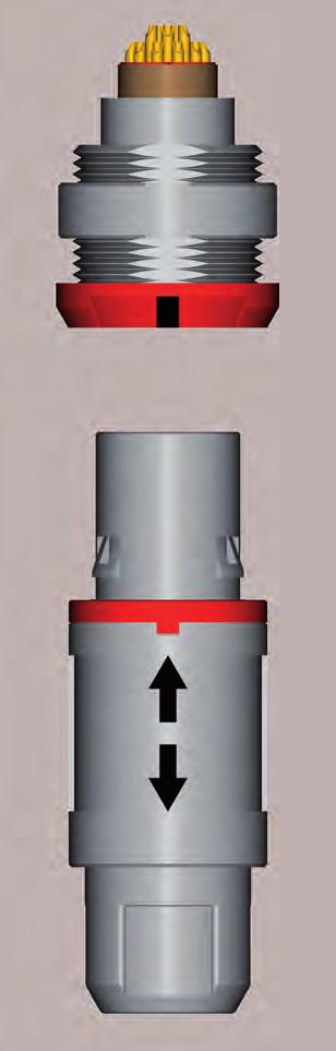
4 Standard models (IP50) C... Fixed socket 1 Outershell 2 Insulator 3 Female crimp contact 4 Hexagonal nut Straight plug 1 Outershell 2 Latch sleeve 3 Insulator 4 Male crimp contact 5 Collet + mid piece 6 Collet nut Characteristics Value Standards Characteristics Value Standards Average retention force when pulling on the cable 1N = kg Cable retention force (depends on cable construction) 1N = kg 150 N IEC test 15f N IEC test 17c Endurance (latching) Working temperature range (PSU) Working temperature range (PEI) > 1000 cycles IEC test 9a -50/+150 C -50/+170 C CAB Straight plug with cable collet CAB.M.GLA.C52G CAB.M.GLA.C72G CAB.M.GLA.C92G Cable ø min max ~53 ~38 ø 18 ø 18 CAB Straight plug with cable collet and nut for fitting a bend relief CAB.M.GLA.C52GZ CAB.M.GLA.C72GZ CAB.M.GLA.C92GZ Cable ø min max Note: the bend relief must be ordered separately (see page 44). ~36.7 ~57 ~51.7 S 13 34

5 C... CKB a Fixed socket with two nuts (back panel mounting) N CKB.M16.GLLG CKB.M19.GLLG CKB.M26.GLLG CKB.M32.GLLG number of contacts Note: for PCB drilling pattern see page 46. Panel hole see page 46. Contact Solder Crimp Print N a max N a c ø d M17x1 4 ø 20.2 ød c S maxi 23.8 Solder + Crimp Print CKB Fixed socket with two nuts with 90º contacts (back panel mounting) number of contacts CKB.M16.GLVG CKB.M19.GLVG CKB.M26.GLVG Note: for PCB drilling pattern see page 46. Panel hole see page M17x mini ø 20.2 A S15.5 A 7 maxi CLB Fixed socket, nut fixing a N CLB.M16.GLLG CLB.M19.GLLG CLB.M26.GLLG CLB.M32.GLLG number of contacts Note: for PCB drilling pattern see page 46. Panel hole see page 46. Contact Solder Crimp Print N a max N a c ø d M17x ød c S maxi 23.8 Solder + Crimp Print 35
6 C... CRB Free socket with cable collet CRB.M.GLL.C52G CRB.M.GLL.C72G CRB.M.GLL.C92G Cable ø min max ~52 ø 18 ø 18 CRB Free socket with cable collet and nut for fitting a bend relief CRB.M.GLL.C52GZ CRB.M.GLL.C72GZ CRB.M.GLL.C92GZ Cable ø min max Note: the bend relief must be ordered separately (see page 44). ~56 ~50.7 S 13 36
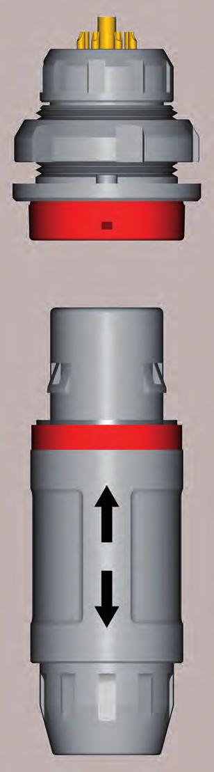
7 Watertight models (IP66) C. M.. Fixed socket 1 Outershell 2 Insulator 3 Female crimp contact 4 Hexagonal nut 5 O-ring Straight plug 1 Outershell 2 Latch sleeve 3 Insulator 4 Male crimp contact 5 Collet + mid piece 6 Collet nut 7 Front seal 8 Gasket Characteristics Value Standards Characteristics Value Standards Average retention force when pulling on the cable 1N = kg 90 N IEC test 15f Endurance (latching) Working temperature range (PSU) > 1000 cycles IEC test 9a -50/+150 C Cable retention force (depends on cable construction) 1N = kg N IEC test 17c Working temperature range (PEI) Index protection -50/+170 C IP66 IEC CFB Straight plug with cable collet and nut for fitting a bend relief CFB.M.GLA.C52GZ CFB.M.GLA.C72GZ CFB.M.GLA.C92GZ Cable ø min max Note: the bend relief must be ordered separately (see page 44). ~36.7 ~57 ~51.7 ø 18 S 13 CNB Fixed socket, nut fixing a N CNB.M16.GLLG CNB.M19.GLLG CNB.M26.GLLG CNB.M32.GLLG number of contacts Note: for PCB drilling pattern see page 46. Panel hole see page 46. Contact Solder Crimp Print N a max N a c ø d M17x1 ød c S maxi 23.8 Solder + Crimp Print 37
8 C. M.. CSB Free socket with cable collet and nut for fitting a bend relief CSB.M.GLL.C52GZ CSB.M.GLL.C72GZ CSB.M.GLL.C92GZ Cable ø min max Note: the bend relief must be ordered separately (see page 44). ~56 ~50.7 ø 18 S 13 38
9 Fluidic models C.. G. Fixed socket 1 Outershell 2 Insulator 3 Female crimp contact 4 Hexagonal nut Straight plug 1 Outershell 2 Latch sleeve 3 Insulator 4 Male crimp contact 5 Collet + mid piece 6 Collet nut Characteristics Value Standards Characteristics Value Standards Average retention force when pulling on the cable 1N = kg Cable retention force (depends on cable construction) 1N = kg 90 N IEC test 15f N IEC test 17c Endurance (latching) Working temperature range (PSU) Working temperature range (PEI) > 1000 cycles IEC test 9a -50/+150 C -50/+170 C CAB Straight plug with cable collet CAB.012.GLA.C52G CAB.012.GLA.C72G CAB.012.GLA.C92G Cable ø min max ~53 ~38 ø 18 CLB Fixed socket nut fixing Number of low voltage contacts Fluidic contact Maximum working pressure (bars) CLB.012.GLLG CLB.015.GLLG CLB.P12.GLLG CLB.P15.GLLG without valve without valve with valve with valve Note: panel hole see page M17x S maxi 39
10 Insert configuration C.... Male solder contacts ø A ø A 1 2 Male crimp contacts 4 3 Female solder contacts Female crimp contacts Reference Number of contacts Contact ø (mm) Solder bucket ø (mm) 5) Crimp bucket ø (mm) 5) Solder Crimp Contact type Print (straight) Print (elbow) Test voltage (kv rms) 1) Contact-contact Air clearance min 2) (mm) Creepage distance min 3) (mm) Rated current (A) M M M M M M Multipole M08 M M M M M ) M M ) Note: 1) depending on specific application and related standard, morerestrictive operating voltage may apply. We suggest operating voltage = 1/3 test voltage, see page 68. 2) shortest distance in air between two conductive parts. 3) shortest distance along the surface of the insulating material between two conductive parts. 4) available only with 26 or 34 contacts, H or J keying (inverted contacts). 5) for a given AWG, the diameter of some stranded conductor design is larger than the solder cup diameter (see page 69). 40
11 C.... Male solder contacts ø A ø A 1 2 Male crimp contacts 4 3 Female solder contacts Female crimp contacts Reference Number of contacts Contact ø (mm) Solder bucket ø (mm) 5) Crimp bucket ø (mm) 5) Solder Crimp Contact type Print (straight) Print (elbow) Test voltage (kv rms) 1) Contact-contact Air clearance min 2) (mm) Creepage distance min 3) (mm) Rated current (A) Coaxial Fluidic 015 P12 6) P15 6) 804 4) 810 4) Note: 1) depending on specific application and related standard, morerestrictive operating voltage may apply. We suggest operating voltage = 1/3 test voltage, see page 68. 2) shortest distance in air between two conductive parts. 3) shortest distance along the surface of the insulating material between two conductive parts. 4) configuration 804 and 810 use «C» type coaxial contact. 5) for a given AWG, the diameter of some stranded conductor design is larger than the solder cup diameter (see page 69). 6) configuration P12 and P15 use fluidic contact with valve (FGG.P1.150.ACV and EGG.P1.150.ACV). Contacts must be ordered separately. 41
12 Alignment key C.... Verify the third digit of the part number in order to select the right keying. The standard keying is «B» coded Keying (plug front view) Reference B H J Contact type for plug Contact type for socket Nb. of contacts male female 2 to 32 female male 26 or 34 female male Outer shell material C.... Material Ref. Colour Temperature PEI PSU PSU S G N Grey Grey Black -50 / +170 C -50 / +150 C Note: for extensive sterilization use PEI Contact type C.... Select the type of contact: solder or crimp? When should I use crimp rather than solder contacts? Plug Type solder crimp Male Female A L 1) C - Soldering recommended for small volumes requires little amount of tooling (soldering iron) requires more time Socket Type solder crimp print print 90º Male Female A 1) L - M - N - V Note: 1) only for H and J keying with 26 or 34 contacts Crimping recommended for large volumes no heat is required to make the connection for contacts with high density for use in high temperature environment requires extra tooling (crimping tools) Colour coding C.... Reference RAL code Colours grey blue yellow black red green G A J N R V Note: the RAL colours are indicative and depend on raw material and production process. Colour may differ. Easy identification with the assistance of colour coding. Outershell is only available in grey or black. 42
 Kit contact part number Male Female M02 M03 M04 M05 M06 M07 M08 M10 M12 M16 M19 CAG.302.YL CAG.303.YL CAG.304.")

13 Accessories CAG-CLG Insulator for crimp contacts CAG-CLG Crimp contacts, kit with the number of contacts in a tube male / white marking female / red marking Contact configuration For male contact Insulator part number For female contact Contact nb. of ø contact configuration contacts (mm) Kit contact part number Male Female M02 M03 M04 M05 M06 M07 M08 M10 M12 M16 M19 CAG.302.YL CAG.303.YL CAG.304.YL CAG.305.YL CAG.306.YL CAG.307.YL CAG.308.YL CAG.310.YL CAG.312.YL CAG.316.YL CAG.319.YL CLG.402.YL CLG.403.YL CLG.404.YL CLG.405.YL CLG.406.YL CLG.407.YL CLG.408.YL CLG.410.YL CLG.412.YL CLG.416.YL CLG.419.YL M M M M M M M M M M M CAG C CAG C CAG C CAG C CAG C CAG C CAG C CAG C CAG C CAG C CAG C CLG M CLG M CLG M CLG M CLG M CLG M CLG M CLG M CLG M CLG M CLG M CAG Collet ø A ø 9.2 CAG.752. CAG.772. CAG.792. ø A (mm) Cable ø (mm) min. max Note: = UGG (grey PSU), UGN (black PSU), TGG (grey PEI) CKG Plastic front nut for CKB models Mat. Colours ø 20.2 M17 x 1 4 CKG.240.UA CKG.240.UG CKG.240.UJ CKG.240.UN CKG.240.UR CKG.240.UV PSU PSU PSU PSU PSU PSU blue grey yellow black red green CAM Nut for fitting a GMA.2B bend relief CAM.130.UG CAM.130.UN CAM.130.TG Mat. PSU PSU PEI Colours grey black grey ø 9.2 ø14.9 S 13 Note: all dimensions are in millimeters 43

14 FGG.P1 Male fluidic contact with valve FGG.P1.150.ACV 27.3 ø 4.4 ø Note: Connectors are delivered without the P1 contacts. EGG.P1 Female fluidic contact with valve EGG.P1.150.ACV 28 ø 4.4 ø Note: Connectors are delivered without the P1 contacts. GMA Bend relief A bend relief absorbs the force that may be exerted on cables. These are designed for plugs and free sockets with cable collet and nut. L ø A GMA.2B.040.DG GMA.2B.045.DG GMA.2B.050.DG GMA.2B.060.DG GMA.2B.070.DG GMA.2B.080.DG GMA.2B.040.RG GMA.2B.045.RG GMA.2B.051.RG GMA.2B.057.RG GMA.2B.063.RG GMA.2B.071.RG GMA.2B.080.RG Dimensions (mm) Bend relief Cable ø A L max. min Material Desmopan 786 Polyurethane elastomer Silicone elastomer VMQ in dry atmosphere Temperature range in water steam -40 C, +80 C -60 C, +200 C +140 C Note: the last letter «G» of the part number indicates a grey colour, see the adjacent table and replace letter «G» by the letter of the colour required. Reference A B G J M N R S V Colours blue white grey yellow brown black red orange green Note: the selection of pigments, which should remain stable at high temperature, is limited by the new regulations. For this reason, some colours will be a shade different from those used for Desmopan bend reliefs. The selected solutions represent the best possible compromise. 44
15 Tooling DPC V Crimping tool DCE Positioners for crimp contacts male female DCF Automatic extraction tools for crimp contacts Type Conductor (mm) Contact ø AWG Male Positioner part number Female Selector No Setting Part number extractor For male contact and female contact M M M04/M05/M06/M M08/M M12/M16/M M26/M DCE BVCM DCE BVCM DCE BVC DCE BVC DCE BVC DCE BVC DCE BVCM DCE BVCM DCE BVM DCE BVM DCE BVM DCE BVM DCC LA 1) DCF LT DCF LT DCF LT DCF LT Note: 1) this model is thumb-operated. This model is used for male and female contacts. The variance in conductor stranding diameter for the minimum AWG is such that some can have a cross section which is not sufficient to guarantee crimping as per IEC standard. DCK Retention testing tools for crimp contacts F Contact ø (mm) Test force (N) Testing tool part number Male contact Female contact DCK LRC DCK LRM DCK LRC DCK LRM DCK LRC DCK LRM Note: all dimensions are in millimeters 45
16 Panel hole For CK, CL, and CN 15.6 ± 0.05 ø min. Note: socket mounting nut torque = 0.8 Nm. PCB drilling pattern For straight contacts ø 4.4 ø x ø x ø ø x ø ø x ø M02 M03 M04 M05 72 ø x ø x ø ø x ø ø x ø ø 6.2 M06 M07 M08 M ø 2.8 ø ' 16 22' ø 3.1 ø ø 3.5 ø ' 12 51' ø 1.6 ø 4.2 ø x ø x ø x ø x ø M12 M16 M19 M ø 2.2 ø ø 7 ø 7.3 ø 4.9 ø x ø ' + 34 x ø M32 M34 46
17 For 90 elbow contacts (A-A view) A A x ø x ø x ø M02 M03 M x ø x ø x ø x ø M05 M06 M07 M08 (6x) x ø x ø x ø x ø (6x) 1.27 M10 M12 M16 M x ø (10x) (5x) 2.54 M
18 Assembly instructions Solder contacts Strip the cable according to the lengths given in the table. Tin the conductors. L T Configuration Dimensions (mm) L T M02 M03 M04, M05, M06, M07 M08, M10, M12, M16, M19 M26, M Slide the collet nut ➀ and then the collet ➁ onto the cable. Solder 3. Solder conductors into contacts, making sure that neither solder nor flux gets onto the insulator or cable insulation. Solder 4. Slide the collet ➁ forward and locate slot ➂ in the key of the insulator ➄. Slide collet nut ➀ over collet ➁ and then push the whole assembly into the shell ➆ whilst positioning it to ensure that the slot ➅ of insulator ➄ locates in the inside key of the shell. Tighten the collet nut ➀ to the maximum torque of 0.5 Nm. For PSU only: We recommend ONLY the use of VTCS-6 Clear Vibra-tite or ThreeBond 1401 to secure the connector backnut. The use of other materials could result in damage to the connector. The only recommended chemical cleaner is Isopropyl Alcohol. 48
19 Crimp contacts L T 1. Strip the cable according to the lengths given in the table. Configuration M02 M03 M04, M05, M06, M07 M08, M10, M12 M16, M19 Dimensions (mm) L T Slide the collet nut ➀ and then the collet ➁ onto the cable. Crimp Crimp 3. Fix the appropriate positioner (table page 45) in the crimping tool. Set selector to the number corresponding to the conductor AWG as indicated on the positioner label. Fit conductor into contact ➃ and make sure it is visible through the inspection hole in the crimp barrel. Slide conductorcontact combination into the open crimping tool; make sure that the contact is fully pushed into the positioner. Close the tool. Remove from crimping tool and check that conductor is secure in contact and shows in inspection hole. 4. Now arrange contact-conductor combinations according to the insert marking and locate them into the insert ➅. Check that all contacts are correctly located and remain in position when given a gentle pull. 5. Slide the collet ➁ forward and locate slot ➂ in the key of the insulator ➄. Slide collet nut ➀ over collet ➁ and then push the whole assembly into the shell ➆ whilst positioning it to ensure that the slot ➅ of insulator ➄ locates in the inside key of the shell. Tighten the collet nut ➀ to the maximum torque of 0.5 Nm. For PSU only: We recommend ONLY the use of VTCS-6 Clear Vibra-tite or ThreeBond 1401 to secure the connector backnut. The use of other materials could result in damage to the connector. The only recommended chemical cleaner is Isopropyl Alcohol. 49
20 Assembly instructions for watertight models Solder contacts Strip the cable according to the lengths given in the table. Tin the conductors. L T Configuration Dimensions (mm) L T M02 M03 M04, M05, M06, M07 M08, M10, M12, M16, M19 M26, M Slide the bend relief 0, the collet nut ➀ and then the collet ➁ onto the cable. Solder 3. Solder conductors into contacts, making sure that neither solder nor flux gets onto the insulator or cable insulation. Fill up completely the inside of the collet ➁ and the gap between conductors with the adhesive/sealant DOW CORNING type 3145RTV. Solder 4. Slide the collet ➁ forward and locate slot ➂ in the key of the insu-lator ➄. Slide collet nut ➀ over collet ➁ and then push the whole assembly into the shell ➆ whilst positioning it to ensure that the slot ➅ of insulator ➄ locates in the inside key of the shell. Tighten the collet nut ➀ to the maximum torque of 0.5 Nm. Push the bend relief 0 onto the collet nut ➀. For PSU only: We recommend ONLY the use of VTCS-6 Clear Vibra-tite or ThreeBond 1401 to secure the connector backnut. The use of other materials could result in damage to the connector. The only recommended chemical cleaner is Isopropyl Alcohol. 50
21 Crimp contacts L T 1. Strip the cable according to the lengths given in the table. Configuration M02 M03 M04, M05, M06, M07 M08, M10, M12 M16, M19 Dimensions (mm) L T Slide the bend relief 0, the collet nut ➀ and then the collet ➁ onto the cable. Crimp Crimp 3. Fix the appropriate positioner (table page 45) in the crimping tool. Set selector to the number corresponding to the conductor AWG as indicated on the positioner label. Fit conductor into contact ➃ and make sure it is visible through the inspection hole in the crimp barrel. Slide conductorcontact combination into the open crimping tool; make sure that the contact is fully pushed into the positioner. Close the tool. Remove from crimping tool and check that conductor is secure in contact and shows in inspection hole. 4. Now arrange contact-conductor combinations according to the insert marking and locate them into the insert ➅. Check that all contacts are correctly located and remain in position when given a gentle pull. 5. Slide the collet ➁ forward and locate slot ➂ in the key of the insulator ➃. Slide collet nut ➀ over collet ➁ and then push the whole assembly into the shell ➆ whilst positioning it to ensure that the slot ➄ of insulator ➃ locates in the inside slot of the shell. Tighten the collet nut ➀ to the maximum torque of 0.5 Nm. Push the bend relief 0 onto the collet nut ➀. For PSU only: We recommend ONLY the use of VTCS-6 Clear Vibra-tite or ThreeBond 1401 to secure the connector backnut. The use of other materials could result in damage to the connector. The only recommended chemical cleaner is Isopropyl Alcohol. 51


22 Exploded view of the REDEL 3P Straight plug backnut seal earthing contact insulator + contacts shell Fixed socket bend relief backnut for a bend relief cable collet insert + contacts shell nut insert nut earthing contact insulator + contacts shell Note: the bend relief must be ordered separately. Fixed socket with square flange hexagonal nut shell front nut insert nut earthing contact insulator + contacts shell finishing cover 52
23 3P SERIES
24 3P Series Historically the 3P is LEMO s first series of completely plastic connectors. It is designed to accommodate cable diameters up to 9.5 mm. Available in 11 different contact configurations including multicontact, and hybrid HV/electrical; coax/electrical; fibre optic/electrical, fluidic, the 3P series has been specifically designed for all applications requiring minimum weight, maximum electrical insulation values, and high thermal and mechanical properties, as well as suitability for either vapour or gas sterilization and for cold sterilization with a chemical product.these connectors provide remarkable safety by using nonconductive materials and four different systems to prevent accidental cross-mating, i. e. colour coding, housing keying, insert keying and insert polarization. Standard models Straight plug Fixed sockets Free socket FGG EGG EBG PHG Alignment keys and insert polarization The 3P series makes it possible for the user to configure his own keying system. The insert can be located into 11 different angular positions relative to the external alignment key. Note: the reference letter: - on the plug insert, is placed to the left of the alignment key. - on the socket insert, is placed to the right of the alignment key. α H Rear view of a socket G J F K E L D A C B Insert code A B C D E F G H J K L Angle Plug Socket ' ' ' ' 81 49' ' 49 05' ' 16 22' ' ' 16 22' ' 49 05' ' 81 49' ' ' ' ' 54
25 Part numbering system Model: (page 56-57) Series: 3P Outershell: Plug Contact configuration (page 58) P = grey PSU N = black PSU.. F G G 3 P P L W D 7 5 X = white PSU. Collet nut colour table 1) : (page 59) G = grey J = yellow A = blue M = brown B = white N = black R = red V = green Collet: 75 = (cable ø 6.7 mm mm) 85 = (cable ø 7.6 mm mm) 95 = (cable ø 8.6 mm mm) Cable fixing type: D = cable seal Insulator: L = PEEK 2) Low voltage contact type 3) : (page 59) W = male to solder Y = male to crimp Model: (page 56-57) Series: 3P Outershell: Free socket Contact configuration (page 58) P = grey PSU N = black PSU.. P H G 3 P N L W D 7 5 X = white PSU. Collet nut colour table 1) : (page 59) G = grey J = yellow A = blue M = brown B = white N = black R = red V = green Collet: 75 = (cable ø 6.7 mm mm) 85 = (cable ø 7.6 mm mm) 95 = (cable ø 8.6 mm mm) Cable fixing type: D = cable seal Insulator: L = PEEK 2) Low voltage contact type 3) : (page 59) W = female to solder Model: (page 56-57) Fixed socket.. E G G 3 P P L W. Collet nut colour table 1) : (page 59) G = grey J = yellow A = blue M = brown B = white N = black R = red V = green Series: 3P Contact configuration (page 58) Outershell: P = grey PSU N = black PSU X = white PSU Low voltage contact type 3) : (page 59) Y = female to crimp W = female to solder N = female for print only for type 306, 310 and 314 Insulator: L = PEEK 2) FGG.3P.306.PLWD75 Straight plug with key and cable seal, 3P series, multipole type with 6 contacts, outer shell in grey PSU, PEEK insulator, male solder contact, D type collet for 6.7 mmm to 7.5 mm diameter cable and grey coloured ring. PHG.3P.310.NLWD75 Free socket with key and cable seal, 3P series, multipole with 6 contacts, outer shell in black PSU, PEEK insulator, female solder contact, D type collet for 6.7 mm to 7.5 mm diameter cable and black coloured ring. EGG.3P.306.PLW Fixed socket with key, 3P series, multipole type with 6 contacts, outer shell in grey PSU, PEEK insulator, female solder contact and grey coloured ring. Note: 1) the variant position of the part number is used to specify the colour of the coloured ring. For grey PSU (material Code P). 2) for the high voltage type «709» use «J» enhanced PEEK material code. The standard colour is grey and nothing is mentionned in the variant position. 3) the letters W or Y are also used for special arrangements. 55
26 Standard models (IP61). 3P.. Straight plug Fixed socket Outershell 2 Retaining nut 3 Round nut 4 Coloured ring 5 Insulator 6 Female contact 7 Male contact (earthing) 1 Outershell 2 Latch sleeve 3 Retaining nut 4 Coloured ring 5 Insulator 6 Male contact 7 Female contact (earthing) 8 Clamping sleeve 9 Clamp 10 Screw 11 Washer 12 Seal Characteristics Value Standards Characteristics Value Standards Average retention force when pulling on the cable 1N = kg Cable retention force (depends on cable construction) 1N = kg 120 N IEC test 15f N IEC test 17c Endurance (latching) Working temperature range 1) (PSU) Watertightness (mated) > 1000 cycles -50/+150 C IP61 IEC test 9a IEC Note: 1) for the type hybrid LV + fibre optic, the temperature is: -40/+80 C FGG Straight plug with key and cable seal FGG.3P..PLWD75 FGG.3P..PLWD85 FGG.3P..PLWD95 Cable ø min max ~63 ~47 ø 18.8 ø


27 . 3P.. EGG Fixed socket with key, nut fixing EGG.3P.306.PLW EGG.3P.310.PLW EGG.3P.314.PLW EGG.3P.318.PLW number of contacts Contact Solder Crimp Print N a max N a c ø d 6+1LV LV LV LV Note: for PCB drilling pattern see page 65. Panel hole see page 65. a c 27 EBG Fixed socket with key, square flange and screw fixing EBG.3P.306.PLW EBG.3P.310.PLW EBG.3P.314.PLW Note: for PCB drilling pattern see page 65. Panel hole see page ø 27 M20 x 1 ø 18.8 ø PHG Free socket with key and cable seal PHG.3P..NLWD75 PHG.3P..NLWD85 PHG.3P..NLWD95 Cable ø min max Note: the picture shows outershell in black PSU. ~55 ø 18.8 ø 26 M20 x 1 ø 18.8 ø 22 ø 26.7 ød 5 maxi Solder + Crimp Print 57
28 Insert configuration. 3P.. Male solder contacts ø A ø A 1 2 Male crimp contacts 4 3 Female solder contacts Female crimp contacts Reference Number of contacts ø A (mm) Solder bucket ø (mm) 5) Solder Crimp Contact type Print (straight) Test voltage (kv rms) 1) Contact-contact Air clearance min 2) (mm) Creepage distance min 3) (mm) Rated current (A) LV Multipole LV LV LV H.V. Hybrid +LV 9+1LV 709 1HV Coaxial Hybrid +LV 9+1LV Coax 6) H 9+1LV 1FO 4) Fibre optic Hybrid +LV 92K 96H 11+1LV 1FO 4) 9+1LV 1FO 4) K 11+1LV 1FO 4) Fluidic Hybrid +LV 3 Fluid LV Note: 1) depending on specific application and related standard, more restrictive operating voltage may apply. We suggest operating voltage = 1/3 test voltage, see page 68. 2) shortest distance in air between two conductive parts. 3) shortest distance along the surface of the insulating material between two conductive parts. 4) fibre optic contact must be ordered seperately (see page 61) 5) for a given AWG, the diameter of some stranded conductor design is larger than the solder cup diameter (see page 69). 6) configuration 809 use «C» type coaxial contact. 58
29 Contact type. 3P.. Select the type of contact: solder or crimp? Plug Socket Type solder crimp Type solder crimp print Colour coding Male W Y Female W Y N When should I use crimp rather than solder contacts? Soldering recommended for small volumes requires little amount of tooling (soldering iron) requires more time Crimping recommended for large volumes no heat is required to make the connection for contacts with high density for use in high temperature environment requires extra tooling (crimping tools). 3P.. Reference RAL code Colours grey blue yellow black red green brown white G A J N R V M B Note: the RAL colours are indicative and depend on raw material and production process. Colour may differ. Easy identification with the assistance of colour coding. Outershell is only available in grey, black or white (see page 55). 59
 (mm) Male Contact part number Female 306 310 314 FGG.3P.306.ML FGG.3P.310.ML FGG.3P.314.ML EGG.3P.406.ML EGG.3P.410.ML EGG.3P.414.ML 306 0.9 1.1 310 0.9 1.1 314 0.9 1.1 FGG.")

30 Accessories FGG-EGG Insulator for crimp contacts FGG-EGG Crimp contacts, kit with the number of contacts in a tube male female Contact configuration For plug Insulator part number For socket Contact ø A ø C configuration (mm) (mm) Male Contact part number Female FGG.3P.306.ML FGG.3P.310.ML FGG.3P.314.ML EGG.3P.406.ML EGG.3P.410.ML EGG.3P.414.ML FGG.3P.306.ZZYT FGG.3P.310.ZZYT FGG.3P.314.ZZYT EGG.3P.306.ZZYT EGG.3P.310.ZZYT EGG.3P.314.ZZYT FGG-EGG Earthing contacts ø A ø C Type ø A (mm) ø C (mm) Male Contact part number Female ø A ø C H - 92H K - 92K FGG.3P.561.ZZY FGG.3P.561.ZZY FGG.3P.561.ZZY FGG.3P.561.ZZY FGG.3P.561.ZZY EGG.3P.661.ZZY EGG.3P.661.ZZY EGG.3P.661.ZZY EGG.3P.661.ZZY EGG.3P.661.ZZY GEB Plastic nut Mat. Colours M20 x 1 6 GEB.3P.240.UB GEB.3P.240.UG GEB.3P.240.UN PSU PSU PSU white grey black ø 26 EBG Finishing cover Mat. Colours EBG.3P.260.UB EBG.3P.260.UG EBG.3P.260.UN PSU PSU PSU white grey black Note: a finishing cover is supplied with all EBG fixed sockets with a square flange. Models EBG sockets, with a square flange, can also be mounted without using the fixing screws. Note: all dimensions are in millimeters 60
31 GMA Bend relief 42 Cut Cable ø (mm) min. max C B A 2.5 ø GMA.3P.050.SN A B C Material: Black thermoplastic rubber Note: the cable entry of the FGG plugs can be fitted with a flexible bend relief which can accommodate cables of 3 to 7 mm in diameter. The adjustment to the diameter is done by cutting the conical end. The bend relief is mounted inside the nut. The cable must have a sheath with a large enough diameter in order to be held by the clamping system. Fibre optic contact For the hybrid type LV + fibre optic, fibre optic contacts must be ordered separately. FFS.F1 Male F1 Fibre Optic Contact for plug Reference Ferrule inside ø (µm) Fibre type ~ 25.5 ø 2.4 FFS.F1.GB1.ACE30 FFS.F1.HB1.AAE30 FFS.F1.JB1.AAE30 FFS.F1.KB1.AAE30 FFS.F1.RB1.AAE30 Note: other ferrule inside diameter, consult us. 235 HCS 335 HCS 435 HCS 640 HCS 1100 Polymer ø 4.4 PSS.F1 Female F1 Fibre Optic Contact for socket Reference Ferrule inside ø (µm) Fibre type 26.2 PSS.F1.GB1.ACE30 PSS.F1.HB1.AAE30 PSS.F1.JB1.AAE30 PSS.F1.KB1.AAE30 PSS.F1.RB1.AAE30 Note: other ferrule inside diameter, consult us. 235 HCS 335 HCS 435 HCS 640 HCS 1100 Polymer ø 4.4 S 4 S 3.5 FFS.F2 Male F2 Fibre Optic Contact for plug Reference Ferrule inside ø (µm) Fibre type ~ 31.2 FFS.F2.BA2.LCE30 FFS.F2.BB2.LCE30 FFS.F2.BD2.LCE30 FFS.F2.BD2.LCE30 FFS.F2.FB2.LCE / / / / /40 ø 4.4 ø 2 Note: all dimensions are in millimeters. 61
 1 2 3 Type RG.174A/U RG.178B/U RG.179B/U RG.187A/U RG.")
 Contact ø AWG Male Positioner part number Female Selector")
32 PSS.F2 Female F2 Fibre Optic Contact for socket Reference Ferrule inside ø (µm) Fibre type ~ 31.2 ø PSS.F2.BA2.LCE30 PSS.F2.BB2.LCE30 PSS.F2.BD2.LCE30 PSS.F2.BD2.LCE30 PSS.F2.FB2.LCE30 Note: all dimensions are in millimeters / / / / /40 ø 4.4 Recommended coaxial cables Group 1) Type RG.174A/U RG.178B/U RG.179B/U RG.187A/U RG.188A/U RG.196A/U RG.316/U Note: 1) the cable group number corresponding to the cable must be written in the variant position of the part number (see page 55). Tooling DPC V Crimping tool DCE Positioners for crimp contacts male female DCF Automatic extraction tools for crimp contacts Contact type Conductor (mm) Contact ø AWG Male Positioner part number Female Selector No Setting Part number extractor For male contact and female contact DCE PVC DCE PVC DCE PVC DCE PVM DCE PVM DCE PVM DCF LT DCF LT DCF LT Note: this model is used for male and female contacts. The variance in conductor stranding diameter for the minimum AWG is such that some can have a cross section which is not sufficient to guarantee crimping as per IEC standard. All dimensions are in millimeters. 62


33 DCC Extraction tool for coax contact type «C» Contact type DCC LA 809 DPE Crimping tool for coax contact type «C» Cable group DPE K DPE K DCP HN Spanners with notch for securing the collet nut DCP HN Spanners for securing the socket nut Material: Black polyamide Material: Black polyamide DCS Polishing tool for fibre optic contact DRV.91.CF2.PN F2 contact fibre optic work station Contact type DCS.91.F24.LC DCS.91.F13.LC F2 F1 Note: all dimensions are in millimeters. 63


34 DPE K Crimp tool for fibre optic contact F1 and F2 type DCC LA Extraction/Installation tool for fibre optic contact F1 and F2 type DCS Microscope adaptor for fibre optic contact WST Epoxy curing oven for fibre optic contact Contact type Voltage DCS.91.G90.6E200 DCS.91.G90.6E240 F2 F1 WST.FR.220.VA WST.FR.110.VA 220 volts 110 volts WST.FB.G Fibre inspection microscope DCS.91.F23.LA Cleaning tool for F2 contact DCS.F2.035.PN F2 contact alignment device installation/extraction tool 64
35 Panel hole For EGG For EBG ø 3 ø 3 ø ø 20.1 ø min. 31 min. PCB drilling pattern For straight contacts ' ø 0.8 ø ø 0.8 ø 3.8 ø 3.8 ø 7.5 ø 8.2 ø
36 Assembly instructions Solder LV contacts L T 1.Strip the cable according to the lengths given in the table. Tin the conductors. In case of a screened cable separate the braid and twist it apart as shown. Configuration Dimensions (mm) L T Solder 2.Slide the retaining nut ➀, the washer ➁, the seal ➂ and the clamping sleeve ➃. In case of a screened cable solder the braid into the earthing contact ➅. Solder 3.In case of a screened cable introduce the earthing contact ➅ into the insert ➇. Check that contact is correctly located and remains in position when given a gentle pull. Solder conductors into contacts, making sure that neither solder nor flux gets onto the insulator or cable insulation. 4.Slide the clamping sleeve ➃ forward and locate tag ➄ into one of the insulator slot according to the selected polarization code. Make sure that same code is used for plug and socket. Tight the screw of the clamping sleeve ➃ to secure the cable. Slide washer and seal against clamping sleeve. 5.Push the whole assembly into the shell ➈ whilst turning it to insure that the tag ➄ is correctly located in the inside slot of the shell. Tighten the retaining nut ➀ to the maximum torque of 1.2 Nm. Socket mounting nut or screws = 2.3 Nm. For PSU only: We recommend ONLY the use of VTCS-6 Clear Vibra-tite or ThreeBond 1401 to secure the connector backnut. The use of other materials could result in damage to the connector. The only recommended chemical cleaner is Isopropyl Alcohol. 66
37 Crimp LV contacts L T 1.Strip the cable according to the lengths given in the table. Tin the conductors. In case of a screened cable separate the braid and twist it apart as shown. Configuration Dimensions (mm) 306, 310, L T Crimp Solder 2.Slide the retaining nut ➀, the washer ➁, the seal ➂ and the clamping sleeve ➃. In case of a screened cable solder the braid into the earthing contact ➅. 3.Fix the appropriate positioner (table page 51) in the crimping tool. Set selector to the number corresponding to the conductor AWG as indicated on the positioner label. Fit conductor into contact ➆ and make sure it is visible through the inspection hole in the crimp barrel. Slide conductor-contact combination into the open crimping tool; make sure that the contact is fully pushed into the positioner. Close the tool. Remove from crimping tool and check that conductor is secure in contact and shows in inspection hole. 4.Now arrange contact-conductor combinations according to the insert marking and locate them into the insert ➄. Check that all contacts are correctly located and remain in position when given a gentle pull. In case of a screened cable introduce the earthing contact ➅ into the insert ➇. Check that contact is correctly located and remains in position when given a gentle pull. 5.Slide the clamping sleeve ➃ forward and locate tag ➄ into one of the insulator slot according to the selected polarization code. Make sure that same code is used for plug and socket. Tight the screw of the clamping sleeve ➃ to secure the cable. Slide washer and seal against clamping sleeve. 6.Push the whole assembly into the shell ➈ whilst turning it to insure that the tag ➄ is correctly located in the inside slot of the shell. Tighten the retaining nut ➀ to the maximum torque of 1.2 Nm. Socket mounting nut or screws = 2.3 Nm. For PSU only: We recommend ONLY the use of VTCS-6 Clear Vibra-tite or ThreeBond 1401 to secure the connector backnut. The use of other materials could result in damage to the connector. The only recommended chemical cleaner is Isopropyl Alcohol. 67
38 Mechanical latching characteristics PSU shell material F v Force (N) Fv Fd Fa Series 1P 2P 3P F d F a PEI shell material Force (N) Fv Fd Fa Series 1P 2P Notes: 1N = kg. Mechanical endurance: 1000 cycles. F v : average latching force F d : average unmating force with axial pull on the outer release sleeve Notes: The forces were measured on PSU outer shells not fitted with contacts. The mechanical endurance represents the number of cycles after which the latching system is still effective (1 cycle = 1 latching/unlatching 300 cycles per hour). The values were measured according to the standard IEC , test 13a. F a : average retention force for straight pull on the collet nut Contact resistance with relation to the number of mating cyles (measured according to IEC test 2a) Average values measured after the mating cycles and the salt spray test according to IEC test 11f. A ø (mm) Contact resistance (mω) 1000 cycles 0.5 < < < < < < 2.9 Note: 1) 21 days at 95% RH according to IEC Insulation resistance between the contacts and contact/shell (measured according to IEC test 3a) Insulating material new after humidity test 1) Multipole PEEK > Ω > Ω Test voltage Test voltage (Ue) : (measured according to the IEC test 4a standard) It corresponds to 75% of the mean breakdown voltage. Test voltage is applied at 500 V/s and the test duration is 1 minute. This test has been carried out with a mated plug and socket, with power supply only on the plug end. Operating voltage (Us) : Ue It is proposed according to the following ratio : Us = 3 Caution: For a number of applications, safety requirements for electrical appliances are more severe with regard to operating voltage. In such cases operating voltage is defined according to creepage distance and air clearance between live parts. Please consult us for the choice of a connector by indicating the safety standard to be met by the product. 68
39 Technical tables Table of American Wire Gauge Table of wire gauges according to IEC standard AWG ) ) ) ) ) 18 1) ) ) ) Construction ø wire max Wire section Strand AWG/ (mm) (in) (mm 2 ) (sq in) nb strand x x x x x x x x x x x x x x x x x x x x x x x x x10-6 Conductor no x Ø (mm) 196x0.40 7x x0.40 7x1.72 1x x0.40 7x1.38 1x x0.30 7x1.50 1x x0.30 7x0.86 1x x0.25 7x0.68 1x x0.25 7x0.52 1x1.4 32x0.20 7x0.43 1x x x0.20 1x1.0 28x x0.20 1x0.80 7x0.25 1x x0.15 7x x x x x0.10 Note: 1) not included in the standard Max Ø Max Ø Section Section (mm) (in) (mm 2 ) (sq in) x x x x x x x x x x x
40 Product safety notice PLEASE READ AND FOLLOW ALL INSTUCTIONS CAREFULLY AND CONSULT ALL RELEVENT NATIONAL AND INTERNATIONAL SAFETY REGULATIONS FOR YOUR APPLICATION. IMPROPER HANDLING, CABLE ASSEMBLY, OR WRONG USE OF CONNECTORS CAN RESULT IN HAZARDOUS SITUATIONS. 1. SHOCK AND FIRE HAZARD Incorrect wiring, the use of damaged components, presence of foreign objects (such as metal debris), and / or residue (such as cleaning fluids), can result in short circuits, overheating, and / or risk of electric shock. Mated components should never be disconnected while live as this may result in an exposed electric arc and local overheating, resulting in possible damage to components. 2. HANDLING Connectors and their components should be visually inspected for damage prior to installation and assembly. Suspect components should be rejected or returned to the factory for verification. Connector assembly and installation should only be carried out by properly trained personnel. Proper tools must be used during installation and / or assembly in order to obtain safe and reliable performance. 3. USE Connectors with exposed contacts should never be live (or on the current supply side of a circuit). Under general conditions voltages above 30 VAC and 42 VDC are considered hazardous and proper measures should be taken to eliminate all risk of transmission of such voltages to any exposed metal part of the connector. 4. TEST AND OPERATING VOLTAGES The maximum admissible operating voltage depends upon the national or international standards in force for the application in question. Air and creepage distances impact the operating voltage; reference values are indicated in the catalog however these may be influenced by PC board design and / or wiring harnesses. The test voltage indicated in the catalog is 75% of the mean breakdown voltage; the test is applied at 500 V/s and the test duration is 1 minute. 5. CE MARKING CE marking means that the appliance or equipment bearing it complies with the protection requirements of one or several European safety directives. CE marking applies to complete products or equipment, but not to electromechanical components, such as connectors. 6. PRODUCT IMPROVEMENTS The LEMO Group reserves the right to modify and improve to our products or specifications without providing prior notification. 70
41 Notes: 71
42 Notes: 72


43 B S K E F A 3T 4A 4M 3K. 93C 1D Y 05 5G 2G 2C L H M R N 03 V W F P D K/S 01 DIN Unipole Multipole Coaxial 50 Ω Coaxial 75 Ω Multi Coaxial Mixed Coax + LV Triaxial 50 Ω Triaxial 75 Ω Mixed Triax + LV Quadrax High Voltage Multi High Voltage Mixed HV + LV Fibre Optic Multi Fibre Optic Mixed FO + LV Thermocouple Fluidic Multi Fluidic Mixed Fluidic + LV included in this catalogue B Series Keyed S Series K Series Keyed E Series F Series Keyed 00 Series 01 Series 0A Series 3T Series 4A Series 4M Series Keyed 3K.93C Series Keyed 1D Series Y Series 05 Series 5G Series Keyed 2G Series Keyed 2C Series L Series Keyed H Series M Series Keyed R Series Keyed N Series Keyed 03 Series Keyed V Series W Series Keyed Cable assembly K/S Series Keyed REDEL F Series P REDEL Series Keyed D REDEL Series 01 Series Keyed VAA Series SAA Series TAA Series No reproduction or use without express permission of editorial or pictorial content, in any manner. LEMO SA reserves the right to modify and improve specifications, at all times, without any notification.
 914 23 20 0 Fax:(+43 1) 914 23 20 11 sales@lemo.at CHINA LEMO Trading (Shanghai) Co.")
44 LEMO HEADQUARTERS SWITZERLAND LEMO SA Chemin des Champs-Courbes 28 - P.O. Box CH-1024 Ecublens Tel. (+41 21) Fax (+41 21) info@lemo.com LEMO SUBSIDIARIES AUSTRIA LEMO Elektronik GesmbH Lemböckgasse 49/E Wien Tel: (+43 1) Fax:(+43 1) sales@lemo.at CHINA LEMO Trading (Shanghai) Co., Ltd LEMO Electronics (Shanghai) Co., Ltd 5th Floor, Block 6, City of ELITE, 1000 Jinhai Road, Pudong Shanghai, China Tel: (+86 21) Fax: (+86 21) cn.sales@lemo.com DENMARK LEMO Denmark A/S Gammel Mosevej Gentofte Tel: (+45) Fax: (+45) info-dk@lemo.com FRANCE LEMO France Sàrl 24/28 Avenue Graham Bell Bâtiment Balthus 4 Bussy Saint Georges Marne la Vallée Cedex 3 Tel: (+33 1) Fax: (+33 1) info-fr@lemo.com GERMANY LEMO Elektronik GmbH Hanns-Schwindt-Str München Tel: (+49 89) Fax: (+49 89) info@lemo.de HONG KONG LEMO Hong Kong Ltd Unit 1207, 12/F, Corporation Square, 8 Lam Lok Street, Kowloon Bay, Kowloon - Hong Kong Tel: (+852) Fax: (+852) hk.sales@lemo.com HUNGARY REDEL Elektronika Kft Nagysándor József u Budapest Tel: (+36 1) Fax: (+36 1) redelemo@lemo.hu ITALY LEMO Italia srl Viale Lunigiana Milano Tel: (+39 02) Fax: (+39 02) sales.it@lemo.com JAPAN LEMO Japan Ltd , Takaido Higashi, Suginami-ku, Tokyo, Tel: (+81 3) Fax: (+81 3) lemoinfo@lemo.co.jp NETHERLANDS / BELGIUM LEMO Connectors Benelux De Trompet DC Heemskerk Tel. (+31) Fax (+31) info@lemo.nl NORWAY / ICELAND LEMO Norway A/S Stanseveien 6B 0975 Oslo Tel: (+47) Fax: (+47) info-no@lemo.com SINGAPORE LEMO Asia Pte Ltd 4 Leng Kee Road, #06-09 SiS Building Singapore Tel: (+65) Fax: (+65) sg.sales@lemo.com SPAIN / PORTUGAL IBERLEMO S.A. Brasil, 45, Granollers Barcelona Tel: (+34 93) Fax: (+34 93) info-es@lemo.com Madrid Office Antonio López, 96, Madrid Tel: (+34 91) Fax: (+34 91) SWEDEN / FINLAND LEMO Nordic AB Mariehällsvägen 39A Bromma Tel: (+46 8) Fax: (+46 8) info-se@lemo.com SWITZERLAND LEMO Verkauf AG Grundstrasse 22 B 6343 Rotkreuz Tel: (+41 41) Fax: (+41 41) ch.sales@lemo.com UNITED KINGDOM LEMO UK Ltd North Street Worthing West Sussex, BN11 1DU Tel: ( ) Fax: ( ) lemouk@lemo.com USA LEMO USA Inc P.O. Box 2408 Rohnert Park, CA Tel: (+1 707) (+1 800) Fax:(+1 707) info@lemousa.com CAT.MH.LEN.P0908 CAT.MP.REN.P1208 LEMO DISTRIBUTORS AUSTRALIA, BRAZIL, CANADA, CZECH REPUBLIC, GREECE, INDIA, ISRAEL, NEW ZEALAND, PAKISTAN, POLAND, RUSSIA, SOUTH AFRICA, SOUTH KOREA, TAI- WAN, TURKEY, UKRAINE 1
Single, Multi & Hybrid. Fibre Optic Connectors
 Single, Multi & Hybrid Fibre Optic Connectors 5 Dear Customers, As far as data transmission is concerned, the superior characteristics of fibre optics compared to electrical cables are clearly recognised
CYLER. Catalogue. Cyler Technology Limited cylerconnectors. Push-Pull connectors
 Push-Pull connectors Catalogue cylerconnectors Selection Guide Where and Why Push-Pull? Industrial and Automation Medical electronics Telecommunication Test and Measurement Quality aesthetics for more
T E C H N I C A L O V E R V I E W LEMO S REMOTE HANDLING CONNECTORS N SERIES
 T E C H N I C A L O V E R V I E W LEMO S REMOTE HANDLING CONNECTORS N SERIES I NTRODUCTION LEMO s N Series connectors are ideally suited for remote handling in nuclear environments. Main Features Push-pull
FISCHER FREEDOM TM SERIES
 K CHAPTER FISCHER TM SERIES EASY MATING EASY CLEANING EASY INTEGRATION KEY FEATURES No key code: 360 mating freedom & optimized cable management Membrane-sealed contacts (patent pending) Low profile IP68
ODU MEDI-SNAP. Miniature Cylindrical Connectors with Push-Pull-Locking in Plastic
 Catalogue No.: 005ME-c-e ODU MEDI-SNAP Miniature Cylindrical Connectors with Push-Pull-Locking in Plastic 2 rue René Laennec 5500 Taissy France Fax: 03 26 85 9 08, Tel : 03 26 82 49 29 E-mail:hvssystem@hvssystem.com
K CHAPTER FREEDOM TM SERIES EASY MATING EASY CLEANING EASY INTEGRATION FISCHER KEY FEATURES
 K CHAPTER FISCHER TM SERIES EASY MATING EASY CLEANING EASY INTEGRATION KEY FEATURES No key code: 360 mating freedom & optimized cable management Membrane-sealed contacts (patent pending) Low profile IP68
SMB LOCK Introduction Characteristics Straight plugs Right angle plugs SMB limited detent (SMB-A) Receptacles...
 Receptacles...") CONTENTS PAGE SMB Introduction... 4 General... 5 Finder guide... 6 Interface... 7 Characteristics...8-9 Straight plugs...0- Right angle plugs...- Jacks... 3 Bulkhead jacks...4-5 Receptacles...6-7 PCB receptacles...
CONTENTS PAGE SMB Introduction... 4 General... 5 Finder guide... 6 Interface... 7 Characteristics...8-9 Straight plugs...0- Right angle plugs...- Jacks... 3 Bulkhead jacks...4-5 Receptacles...6-7 PCB receptacles...
Multipole Low Voltage Connectors
 Connectors 4 Introduction Key Features Wide range of body styles and sizes Unsealed, sealed or hermetic etic Signal or power Multipole up to 55 contacts Up to 30 A Standard or inverted polarity Solder,
Directory chapter 03 DIN Power (to 15 A) Types H, H 3, MH , MH Technical characteristics type H
 Types H, H 3, MH , MH Technical characteristics type H") Directory chapter 03 () Types H, H 3, MH 24 + 7, MH 21 + 5 Page Technical characteristics type H.................................... 03.10 Type H connectors.................... 03.11 Type H 3 connectors..................
Directory chapter 03 () Types H, H 3, MH 24 + 7, MH 21 + 5 Page Technical characteristics type H.................................... 03.10 Type H connectors.................... 03.11 Type H 3 connectors..................
9316 series Underwater applications Explosion proof Hermetically sealed
 Branche Connecteurs Offshore 9316 series Underwater applications Explosion proof Hermetically sealed Summary 9316 1 Introduction 2 Presentation 3 Technical characteristics 4 Synopsis 5 Part-numbering system
MMC RTX series EN3716
 MMC RTX series EN3716 7 CONTENTS Page Introduction... 7-4 Application 7-4 Features... 7-4 Product overview... 7-5 Electrical characteristics... 7-6 Mechanical & environmental characteristics... 7-6 Products
General characteristics and technical data Series MCS
 MOD M MC MCS VP 100 S Operating voltage up to 5 kvdc Operating current up to 4,5 A 2-6 high voltage contacts Quick and easy assembling Protection class IP68 acc. DIN EN 60529 General characteristics and
Operating voltage up to 5 kvdc Operating current up to 4,5 A 2-6 high voltage contacts Quick and easy assembling Protection class IP68 acc.
 Operating voltage up to 5 kvdc Operating current up to 4,5 A 2-6 high voltage contacts Quick and easy assembling Protection class IP68 acc. DIN EN 60529 General characteristics and technical data Series
8STA/8TA Series. Compact Circular Connectors Derived from MIL-DTL & JN1003. Connection Technologies
 8STA/8TA Series Compact Circular Connectors Derived from MIL-DTL-38999 & JN1003 Connection Technologies 8STA/8TA Series Contents Overview Presentation... 06 Applications... 06 Features & benefits... 07
FISCHER CORE SERIES STAINLESS STEEL
 TECHNICAL SPECIFICATIONS FISCHER CORE SERIES Fischer Connectors SA All rights reserved Web version 1.6-06.2017 Changes without prior notice FISCHER CORE SERIES FISCHER CORE SERIES KEY FEATURES The Fischer
Amphenol. eries SJT. Series SJT. VG 96912, Series 1 PAN JN 1003
 Amphenol eries SJT Series SJT VG 96912, Series 1 PAN 6433-2 JN 1003 Ordering information Ordering example: SJT G 06 RT 14-35 P A 014 Series (p. 9, 15, 18) SJT Scoop proof (100% scoop-proof) Junior (Miniature
Han K 3/0, K 3/2 / Han HC Modular. Contents Technical characteristics Han K 3/0, Han K 3/ Inserts Han K 3/0, Han K 3/
 Han K 3/0, K 3/2 / Han HC Contents Page Technical characteristics Han K 3/0, Han K 3/2... 14.02 Inserts Han K 3/0, Han K 3/2... 14.03 Hoods/Housings Han 24 HPR for Han K 3/0, Han K 3/2... 14.04 Technical
FISCHER ULTIMATE TM SERIES RUGGED COMPACT LIGHTWEIGHT KEY FEATURES
 H CHAPTER PAGES FISCHER TM SERIES RUGGED COMPACT LIGHTWEIGHT KEY FEATURES IP68 to -0m / IP69 / Hermetic 60 EMC shielding High corrosion resistance 0,000 mating cycles H - FISCHER TM SERIES Table of contents
General characteristics
 Multipole Industrial Connectors General characteristics The multipole connectors for industrial purposes are used in electric and electronic machinery, robots, electric panels, control equipments and wherever
T SERIES IP 68 PUSH-PULL CONNECTORS
 T SERIES IP 68 PUSH-PULL CONNECTORS T series T series connectors have been specifically designed for outdoor applications. They include an inner sleeve and seals to prevent penetration of solids or liquids.this
SEK Solder board connectors
 Solder board connectors Technical characteristics 6, 10, 14, 16, 20, 26, 30*, 34, 40, 50, 60, 64 Contact arrangement straight, angled Contact length 2.9 mm, 4.5 mm Approvals IEC 603-13 DIN EN 60 603-13
Push-Pull connectors
 Push-Pull connectors Introduction This catalog presents the push-pull connectors ranges for industrial applications. These products are particularly suitable for high reliability and high quality applications
Directory chapter 08. InduCom Robust and EMI protected D-Sub interfaces
 Directory chapter 08 Robust and EMI protected D-Sub interfaces New Page General information.............................................. 08.02 Mounting details................................................
Crimpmate Range pitch 5.00
 Contents pitch. pitch. pitch. Male and female connectors with solder connection. Male and female connectors with crimp connection. Crimp contacts..1 pitch. RSV 1. S Derating curve RSV1. S SN Rectangular
HIGH-QUALITY; LOW-COST; RELIABLE &PEFECT; SUPERIOR CUSTOMER SERVICE; HOW DO WE DO IT?
 HIGH-QUALITY; LOW-COST; RELIABLE &PEFECT; SUPERIOR CUSTOMER SERVICE; HOW DO WE DO IT? Inte-Auto Technology Committed to Providing the Best Value with Superior Customer Service Inte-Auto Technology is dedicated
Operating voltage up to 5 kvdc Operating current up to 4,5 A 2-6 High voltage contacts Quick and easy assembling Protection class IP68 acc.
 Operating voltage up to 5 kvdc Operating current up to 4,5 A 2-6 High voltage contacts Quick and easy assembling Protection class IP68 acc. DIN EN 60529 General characteristics and technical data Series
6000 Series Buccaneer. Secure, quick connector mating and release. 30 twist locking Tamperproof lock prevents accidental un-mating
 circular that combine the ease of use of a push/pull coupling mechanism with proven environmental sealing. Available with metal or plastic bodies, the range supports both data (USB and Ethernet), signal
8N45S NC Series Non-safety classified connectors for EPR reactors
 Description Quick-connect ¼ turn bayonet coupling mechanism Straight backshell with sealing gland and cable clamp Integrated 60 ground termination mechanism compliant with EPR reactors wiring specifications
Luminus Series Amphenol Pcd
 Luminus Series Amphenol Pcd Amphenol Pcd Pcd is is one one of of the the world s leading suppliers of of interconnect products for for Military, Commercial Aerospace and and Industrial applications. Located
HyperGrip - Push/Pull Plastic Circular Connectors
 A B C D E F G H J K HG2 HG3 HG4 Ø1.014 [25.76] 1.220 [30.98] Ø0.866 [22.00] 0.272 [6.91] 1.637 [41.59] 3.265 [82.93] Ø0.502 [12.75] Ø0.656 [16.66] 2.700 [68.56] 3.724 [94.60] Ø1.172 [29.77] 1.137 [28.87]
RF COAXIAL CONNECTORS, TYPE SMA, 50 OHMS (MALE CONTACT) ESCC Detail Specification No. 3402/001
 ESCC Detail Specification No. 3402/001") Page 1 of 68 RF COAXIAL CONNECTORS, TYPE SMA, 50 OHMS (MALE CONTACT) ESCC Detail Specification Issue 3 January 2014 Document Custodian: European Space Agency see https://escies.org PAGE 2 LEGAL DISCLAIMER
Page 1 of 68 RF COAXIAL CONNECTORS, TYPE SMA, 50 OHMS (MALE CONTACT) ESCC Detail Specification Issue 3 January 2014 Document Custodian: European Space Agency see https://escies.org PAGE 2 LEGAL DISCLAIMER
USA Canada On the Internet: Toll Free wieland Product Range Electrical Connections
 0.2 F 01/02 270 Excerpt from our master catalogue wiecon PCB terminals In Ageneral, all Wieland components which are obliged to have the identification are provided with the A mark Pluggable PCB terminals
06. har-mik INTERFACE CONNECTORS
 . INTERFACE CONNECTORS Miniature D connectors are a must in various cableto-board applications where space saving and high data transfer rates are required. For the purposes of miniaturization and speed,
Electrical Voltage rating Test Voltage (Vrms) service rating sea level at 21000m M N I II
 service rating sea level at 21000m M N I II") JVS ronze Series pplications Navy vessels - Military - Merchant fleet - Transportation - Oceanography - attle-field cables, shelters - Signalling - ield equipments Standards MIL- 38999 Series III 75 201.002
JVS ronze Series pplications Navy vessels - Military - Merchant fleet - Transportation - Oceanography - attle-field cables, shelters - Signalling - ield equipments Standards MIL- 38999 Series III 75 201.002
RF COAXIAL CONNECTORS, TYPE SMA, 50 OHMS (FEMALE CONTACT) ESCC Detail Specification No. 3402/002
 ESCC Detail Specification No. 3402/002") Page 1 of 106 RF COAXIAL CONNECTORS, TYPE SMA, 50 OHMS (FEMALE CONTACT) ESCC Detail Specification Issue 5 June 2016 Document Custodian: European Space Agency see https://escies.org PAGE 2 LEGAL DISCLAIMER
Page 1 of 106 RF COAXIAL CONNECTORS, TYPE SMA, 50 OHMS (FEMALE CONTACT) ESCC Detail Specification Issue 5 June 2016 Document Custodian: European Space Agency see https://escies.org PAGE 2 LEGAL DISCLAIMER
Electronic Circuit Breaker ESS20-0..
 Electronic Circuit Breaker ES-0.. Description Electronic circuit breaker type ES-0.. is designed to ensure selective disconnection of individual loads in systems which are powered by a DC 4 V switch-mode
I Non-magnetic D-Sub Connectors
 Non magnetic D-Sub Connectors Section I Non-magnetic D-Sub Connectors 5 Non magnetic D-Sub Contents Non magnetic D-Sub Connectors Cross reference table for ESA/SCC/SOURIAU/GSFC...7 Quality Assurance Testing...7
4000 Series Buccaneer
 Sealed to IP66 IP6 and IP69K when mated IP6 rating tested at 1.054kg/sq cm (15lb/sq in) m depth for 2 weeks, & pole configuration Power ratings up to 1A, 600V Cable range from to 7mm Diameter over coupling
Connectors Type M DIN / IEC Catalog E /01 Edition 1
 Connectors Type M DIN 41612 / IEC 60603-2 www.erni.com www.erni.com Contents General Information 3 Electrical & Mechanical Specifications for Connectors 4 Standard Male Connectors for Daughtercards 6 Standard
Application Specification Circular Plastic Connector (CPC) Series 45 System 05 AUG 14 Rev D
 Series 45 System 05 AUG 14 Rev D") Application Specification Circular Plastic Connector (CPC) 114-13137 Series 45 System 05 AUG 14 Rev D NOTE i All numerical values are in metric units [with U.S. customary units in brackets]. Dimensions
Application Specification Circular Plastic Connector (CPC) 114-13137 Series 45 System 05 AUG 14 Rev D NOTE i All numerical values are in metric units [with U.S. customary units in brackets]. Dimensions
TE Connectivity DEUTSCH Single Module EN4165 connectors
 Applications Cabin and avionic systems High-performance military aircraft Commercial airlines Communications equipment Missiles Military Railway TE Connectivity DEUTSCH Single Module EN4165 Connectors
for Quadrax and ELIO 8
 1 - CHARACTERISTICS Mechanical Current ratings, continuous: Endurance: 500 matings Insertion and extraction forces, max: - shell size 1: 120 N (27 Ibs) - shell size 2: 267 N (60 Ibs) - shell size 3: 467
RECTANGULAR CONNECTORS PER ARINC 404 RM-RME SERIES
 Rev. C, March, 2016 RECTANGULAR CONNECTORS PER ARINC 404 RM-RME SERIES Connectors with wide range of shell configurations/modifications, contact arrangements and contacts to meet ARINC 404 Specification
DISPOSABLE COST-EFFECTIVE EASY TO USE MODULAR KEY FEATURES
 B10 CHAPTER FISCHER CORE SERIES DISPO COST-EFFECTIVE EASY TO USE MODULAR KEY FEATURES Sterilizable (EtO), gamma) Color-coded for easy integration Single or two-piece shell Lightweight and shock resistant
Thermal-Magnetic Circuit Breaker 201/-WA
 Thermal-Magnetic Circuit Breaker 0/-WA Description Single pole thermal-magnetic circuit breaker with tease-free, trip-free, snap action mechanism and two button operation (M-type TM CBE to EN 60934). Featuring
fischer ultralight connectors AluLite series new Edition 1.0
 fischer ultralight connectors AluLite series new Edition.0 fischer ultralight connectors New AluLite series When weight matters Are weight considerations significant in the design and development of your
7000 Series Buccaneer
 The all plastic and metal construction of the - circular that combine the ease of use of a quick coupling mechanism with proven environmental sealing for signal and mains power. Designed and independently
7000 Series Buccaneer
 Robust, rapid connections for harsh environments The all plastic construction 7000 Series Buccaneer - circular that combine the ease of use of a quick coupling mechanism with proven environmental sealing
EN3716 SAE AS81659 ARINC
 6 DSX RTX Series series SAE AS81659 EN3716 ARINC 404 Page Introduction... 6-4 Applications... 6-5 DSX SAE AS81659 Product overview... 6-6 Technical characteristics :... 6-7 & 6-8 Electrical... 6-7 Mechanical
AB05 Series Miniature Bayonet Coupling Connectors
 AB05 Series Miniature Bayonet Coupling Connectors Assembly and Wiring Instructions - Product Introduction: AB05 connectors conform to the Stringent requirements of BS9522 F0017, and US Specification Mil-C-26482,
Han-Power Energy Bus Components
 HARTING Electric Han-Power Energy Bus Components People Power Partnership Han Data Sheet 0080-7 Han-Power T Han-Power T Part-Number Drawing Dimensions in mm 09 12 008 4701 Cable gland please order separately
Waterproof Series Waterproof
 Waterproof Series Waterproof Technical Data Panel connector Panel connector, cable connector and coupler connector circular housing Locking screw connection Protection IP 65 with flat-gasket for panel
K2 Qualified Connectors for EPR Reactor
 Reactor Class 1E connector with quick connect 1/4 turn bayonet coupling and shielding continuity designed to operate during normal & seismic conditions. K2 Qualified / RCC-E 2005 Compliant with EPR wiring
Electrical Dielectric withstanding Altitude Service At ground 1500 Vrms m 600 Vrms m 400 Vrms m 200 Vrms
 Applications Engine area/sensors in harsh environments, railways (brake system), for all purposes in severe climatical environment and high temperature. Standards NFL 54143 - EN 2997 Description Screw
Spare parts 3B 3K 0B 0K 1B 1K 4B 4K 2B 2K 5B 5K 3B 3K. Insulators for crimp contacts. Insulator part number Male contact Female contact
 SPARE PARTS Spare parts FGG-EGG Insulators for crimp contacts male female Insulator part number Male contact Female contact Insulator part number Male contact Female contact 00 0B 0K B K 2B 2K 3B 3K 302
EPIC CIRCON M23 Series
 M23 Series EPIC EPIC CIRCON M23 Series Application Advantage Rugged nickel-plated, die-cast zinc body Positive vibration protection for use with motor drives and moving assemblies Integral EMC cable gland
Amphenol LTW FLO Products Series. Market
 FLO Series FLO I Product Series Amphenol LTW FLO Products Series A new product line of metal push-pull connector series intermateable with Fischer, Lemo, and ODU. FLO series offers a quick and easy mating
Electrical Test voltage (Vrms) Service sea level at m M I II
 Service sea level at m M I II") 8LT eries Applications High density connectors for all military and aeronautical purposes. tandards MIL-C 38999 eries I - QPL approved NC 93422 HE 308 DTAT-C 5935 X 0005 (HE 308 standard) GAM/T1 list Description
8LT eries Applications High density connectors for all military and aeronautical purposes. tandards MIL-C 38999 eries I - QPL approved NC 93422 HE 308 DTAT-C 5935 X 0005 (HE 308 standard) GAM/T1 list Description
Water-Proof Connectors
 Water-Proof Connectors Edac s waterproof Wire-to-Wire and Wire-to-Board series was designed for both extreme moisture and nonsubmersion applications supporting both low-level signal and power applications
HYDROCON Standard Sealed Connectors
 HYDROCON Standard Sealed Connectors Ratings: 2 & 3 Pole 10A 250V AC/DC 4 Pole 6A 250V AC/DC 6 & 7 Pole 3A 250V AC/DC 9 Pole 5A 150V AC/DC 25 Pole 1A 50V AC/DC Contact Resistance:
900 Series Buccaneer BUCCANEER FOR POWER. IP68 rating tested at 1.054kg/sq cm (15lb/sq in) 10m depth for 2 weeks. Trailing Neutral on 5 pole
 10m depth for 2 weeks. Trailing Neutral on 5 pole") IP68 rating tested at 1.054kg/sq cm (15lb/sq in) 10m depth for 2 weeks 32A, 600V ac/dc rating 2, 3, 4, 5, 7 and 10 pole Plug or socket connection in each body style Water and dustproof to IP68 when mated
IP68 rating tested at 1.054kg/sq cm (15lb/sq in) 10m depth for 2 weeks 32A, 600V ac/dc rating 2, 3, 4, 5, 7 and 10 pole Plug or socket connection in each body style Water and dustproof to IP68 when mated
Castellated/Hex Nut. Insert Retaining Ring. Contact Insert
 Castellated/Hex Nut Seals Snap-on Connection for Flexible Straps & Covers Insert Retaining Ring Contact Insert Sealing Cap Clip Gland Cage Insert Retaining Ring Contact Insert Locking Ring Flex Body Moulding
Standard Buccaneer IP68 BUCCANEER FOR POWER BUCCANEER POWER
 IP68 Castellated/Hex Nut Seals Snap-on Connection for Flexible Straps & Covers Insert Retaining Ring Insert Retaining Ring Contact Insert Locking Ring Flex Body Moulding Contact Insert Sealing Cap Clip
400 Series Buccaneer BUCCANEER POWER. bulgin
 bulgin BUCCANEER FOR POWER Contact Retainer Sealing Gasket O Ring Contacts Locking Ring Retaining Nut Panel Body Contacts Contact Carrier O Ring Main Body Cable Gland Collet Gland Nut Sealed to IP68 when
CONEC provides reliable and effective solutions to OEM, EMS and cable houses.
 CONEC CANADA USA CONEC designs and manufactures products in modern facilities. The products are made in accordance to the highest quality standards and industry specifications. CONEC provides reliable
HARTING. Interface Connectors. People Power Partnership
 11 4 HARTING Interface Connectors People Power Partnership People Power Partnership Quality Connections Worldwide HARTING was founded in 1945 by the family that still owns the company. Today, HARTING employs
Han Q 1/0 Axial Screw Protected. Available February 2017
 Features Compact connector based on size 3 A with a current carrying capacity of 100 A Space saving design due to an angled malemale version IP20 protected male and female contact according to IEC 60 529
CL-3/1297 CGL INDUSTRIAL POWER INPUT CONNECTORS UP TO 700 V
 CL-3/1297 INDUSTRIAL POWER INPUT CONNECTORS UP TO 700 V Contents Introduction... 2 Features... 3 How to Order... 4 Part Number Explanation... 5 Technical Data... 6 250 / 500 Volt Contact Arrangements...
 This publication is issued to provide outline information only and unless specifically agreed to the contrary by WEALD ELECTRONICS LTD. in writing, is not to form part of any order or contract or be regarded
HERMETIC. Hermetic Connectors. High Performance Sealing Solutions
 HERMETIC Hermetic Connectors High Performance Sealing Solutions Hermetic Connectors 38999 QPL Qualified Presentation Based on glass to metal seal technology, SOURIAU offers hermetic connectors to cover
M8 Series. Key features: BUCCANEER
 Bulgin s M8 circular connectors and overmolded cables are designed to fulfil the ever growing demand for sensor, actuator and data connections in process control, industrial machinery and factory automation
Our Most Important Connection is with You. SECTION 2 SMPM / SMP / SMP-LOCK / SMP-COM R201 / R222 / R222L / R2229
 SECTION 2 SMPM / SMP / SMP-LOCK / SMP-COM R201 / R222 / R222L / R2229 Contents SMPM Introduction... 2-4 Interface... 2-5 Characteristics... 2-6 Plugs and Jacks... 2-7 Receptacles and panel shrouds... 2-8
1mm Pitch Cable-to-Board Connectors supporting LVDS signal
 NEW 1mm Pitch Cable-to-Board Connectors supporting LVDS signal FX Series Space saving, Equal length transmission lines Patent pending Fig.1 Termination side:.5 mm pitch, 1-row construction Mating side:
LMV RANGE CONTENTS. General information
 General information LMV RANGE CONTENTS Basic safety information. 2 Main features...... 3 Intermateability.. 3 Characteristics....... 4 Connection system.... 4 Ordering information Standard connector part
17 TW SERIES. Hybrid Connector SPECIFICATIONS: MATERIALS AND PLATINGS ELECTRICAL DATA CLIMATIC DATA MECHANICAL DATA
 17 TW SERIES Hybrid onnector mphenol s 17TW series hybrid -Subminiature connectors are available with power, coax, high voltage and signal contacts assembled in the same connector body. These connectors
Technical Data, High Power 2-way* Cannon APD / ISO Connectors. Electrical Data. Mechanical Data. Environmental Data (acc.
 Technical Data, High Power 2-way* Electrical Data Operating Voltage Operating Current Contact Resistance Voltage Proof Insulation Resistance Mechanical Data 48 VDC* see derating curve 2 mω max. 1000 VAC,
Filter Connectors / D*J
 Features/Benefits D*Sub Filtration 4000 to 12000 pf Direct filtration included inside the connectors Burning and LAT test included EPPL Listed connector Typical Applications To be used where filtration
SRC SERIES. Signal Connectors with bayonet locking system. Derived from VG95234 & in accordance with the NF F standard
 SERIES Signal Connectors with bayonet locking system Derived from VG9523 & in accordance with the NF F 61-030 standard SERIES /// SIGNAL CONNECTORS Contents Main Characteristics... 2 Synoptic...3- Synoptic:
PRODUCT SPECIFICATION
 MultiCat TM In-line Power Connector System WIRE-TO-WIRE AND WIRE-TO-BOARD MALE CRIMP CONTACT (201845-00X0) FEMALE CRIMP CONTACT (201846-00X0) PLUG HOUSING (201840-00XX) RECEPTACLE HOUSING (201841-00XX)
Datasheet. System pitch mm (0.400 inch) - SU/BU BUZ 10.16HP/02/180F AG BK BX
 - SU/BU BUZ 10.16HP/02/180F AG BK BX") High-performance female connector with the tried-and-tested, guaranteed zero-maintenance, Weidmüller steel clamping yoke. Side-by-side mounting without losing any poles or with patented multifunction flange
High-performance female connector with the tried-and-tested, guaranteed zero-maintenance, Weidmüller steel clamping yoke. Side-by-side mounting without losing any poles or with patented multifunction flange
Contents Technical characteristics Han A Technical characteristics Han 3 A with HARAX Termination
 Contents Page... 01.02 3 with HRX Termination... 01.04 3, 3 with HRX Termination... 01.05 4... 01.06 10... 01.07 16... 01.08 32... 01.09 01 Features Metal and plastic version available 3 hoods/housings
CMC Hybrid Connectors Standard and Power Versions
 CMC hybrid connectors and mating headers provide sealed, high-density, modular and cost-effective wire-to-board and wire-to-wire connection systems for heavy-duty powertrain and body-electronics applications
Bodies Brass Nickel or Gold Gold Female: Beryllium copper Insulator Teflon N/A Crimp ferrule Annealed copper Nickel or Gold
 Materials Connector part Material Finish Bodies Brass Nickel or Gold Center Contact Male: Brass Gold Female: Beryllium copper Insulator Teflon N/A Crimp ferrule Annealed copper Nickel or Gold Electrical
PEGASUS SERIES. Amphenol Pcd. Amphenol Pcd
 PEGASUS SERIES Amphenol Pcd Amphenol Pcd is one of the world s leading suppliers of interconnect products for Military, Commercial Aerospace and Industrial applications. Located north of Boston in Beverly,
Technical Data, 4-way. Cannon APD / ISO Connectors. Electrical Data. Mechanical Data. Environmental Data (acc. ISO 15170) Materials List
 Materials List") Technical Data, 4-way Cannon APD / ISO 15170 Connectors APD 4-way connectors are the original DIN72585 (now ISO 15170) versions using a 2,5 mm contact system. Designed for automotive applications they
Technical Data, 4-way Cannon APD / ISO 15170 Connectors APD 4-way connectors are the original DIN72585 (now ISO 15170) versions using a 2,5 mm contact system. Designed for automotive applications they
Assembly instruction APD 6-/7-way
 Seite 1 von 14 Fixed connector Jam nut receptacle Assembly instruction Free connector Fixed connector Flange receptacle APD-1AP6, 6-way for stamped contacts APD-1AP6-EP 6-way for press in contacts APD-1AP7-EP
38999 All In One! Series III Integrated Backshell
 38999 Series III Integrated Backshell 38999 All In One! Plug with integrated backshell: all the features and the benefits of 38999 Series III connectors now ready to use. Embedded backshell EMI backshell
... A Vital Part of Connection World CMPTER. Cable Connectors PCB Connectors Assembly Instructions Mounting Holes MCX CONNECTORS
 ... A Vital Part of Connection World Cable Connectors PCB Connectors s Mounting Holes MCX CONNECTORS COPYRIGHT ELECTRONICS 0 MCX Series Coaxial Connectors DESCRIPTION MCX connector are developed in Europe
SP Series - Part Numbering
 SP Series - Part Numbering Features Push-pull self latching technology Ultra precision High contact density High reliability / durability High vibration and outer force resistance Applications Telecommunications
RF Coaxial Connectors SMZ (Type 43)
") SMZ (Type 43) Introduction The ITT Cannon range of SMZ connectors are extensively used in 75 communication systems and have become the recognised standard in telecommunications in many parts of the world.
SMZ (Type 43) Introduction The ITT Cannon range of SMZ connectors are extensively used in 75 communication systems and have become the recognised standard in telecommunications in many parts of the world.
CATALOGUE. Connecting devices for actuators and sensors Proximity switches
 CATALOGUE Connecting devices for actuators and sensors Proximity switches Reference rules: IEC 60335-1 Household and similar electrical appliances - Safety IEC 60730-1 Automatic electrical controls for
AMPHENOL PCD SHENZHEN ASGTC. Ruggedized Connector Series for Rail & Mass Transit and Other Harsh Environmental Applications.
 AMPHENOL PCD SHENZHEN ASGTC Ruggedized Connector Series for Rail & Mass Transit and Other Harsh Environmental Applications 1 www.amphenolpcd.com.cn CONTENT CONTENT ASGTC Series Connector structure.........
D-Sub Connectors. Catalog E /09 Edition 3
 www.erni.com Catalog E 074573 11/09 Edition 3 www.erni.com www.erni.com Catalog E 074573 11/09 Edition 3 www.erni.com Table of Contents General..............................................................................................2
Installation Instructions (Translation) Marking. Description. Danger, warning and note symbols. Technical data. ANTARES ExtSet.
 Marking. Description. Danger, warning and note symbols. Technical data. ANTARES ExtSet.") Description Marking The ANTARES ExtSet makes it possible to distribute the Remote I/O ANTARES modules of an explosion-protected Remote I/O system ANTARES among a maximum of 4 metal mounting rails. For
Description Marking The ANTARES ExtSet makes it possible to distribute the Remote I/O ANTARES modules of an explosion-protected Remote I/O system ANTARES among a maximum of 4 metal mounting rails. For
PRODUCT SPECIFICATION
 MICRO-FIT BMI FLOATING CONNECTOR SYSTEM 1.0 SCOPE This Product Specification covers the 3.00 mm (.118 inch) centerline (pitch) connector system terminated with 20 to 30 AWG wire using crimp technology
3.3 mm Contact Pitch, Connectors for Internal Power Supplies
 . mm Contact Pitch, Connectors for Internal Power Supplies DF Series Complete Locking Function Completely enclosed locking system Protection from shorts circuits between adjacent Contacts Features 1. 5
Modular Bayonet connectors: a flexible solution for data and signals transmission in railways harsh environment.
 GM Modular Bayonet connectors: a flexible solution for data and signals transmission in railways harsh environment. Passenger control Networking and lighting control Diagnostic support for brakes, motors
MIL-DTL Series IV Connectors
 DEPENDABLE Secure breech lock coupling 100% scoop-proof Pin-to-pin mating protection helps prevent failures RUGGED Mated connectors help withstand high-impact shock Rear accessory threads help provide
Units with pedestal and busbars on the short side (+H360, flat mounting)
") 91 Units with pedestal and busbars on the short side (+H360, flat mounting) Delivery check Check that there are no signs of damage. Before attempting installation and operation, check the information on
91 Units with pedestal and busbars on the short side (+H360, flat mounting) Delivery check Check that there are no signs of damage. Before attempting installation and operation, check the information on
HVP deg 1pos Plug&Header Connector Assy APPLICATION SPECIFICATION
 HVP1100 90 deg 1pos Plug&Header Connector Assy APPLICATION SPECIFICATION A1 Add Crimp Spec for 50mm2 Cable IY RP 08MAY17 PR: J.LI DATE: 25SEP15 CHK:XX.LI DATE: 27OCT15 APP: I.YIN DATE:21NOV15 Document