WORLDWIDE PROVIDER DUST FILTERS COMPONENTS
|
|
|
- Augusta Jacobs
- 5 years ago
- Views:
Transcription


1 WORLDWIDE PROVIDER DUST FILTERS COMPONENTS CERTIFIED HEADER TANKS DIAPHRAGM VALVES ELECTRONIC SYSTEMS
2 INDEX Team... 5 Research and development... 7 Certificates... 8 TURBO HEADER TANKS Technical features Range Header tanks How to order Global immersion header tanks " Integral series with ½ Dn valves " Integral series with ¾" Dn valves " Integral series with 1" Dn valves " Integral series with ¾" Dn valves " Integral series with 1" Dn valves " Integral series with 1½" Dn valves " Integral series with 1" Dn valves " Integral series with 1½" Dn valves " Integral series with 1½" Dn valves " Integral series with 2" Dn valves " Integral series with 2½" Dn valves " Integral series with 2½" Dn valves " Integral series with 3" Dn valves " Integral series with 3" Dn valves " Integral series with 3½" Dn valves Header tanks with threaded stubs - TF Series TF series Dn 5" - 6" - 8" - 10" - 12" - 14" Header tanks with threaded stubs for straight through valves - Series TL TL series Dn 6" - 8" Header tanks with plain stubs - TD Series TD series Dn 5" - 6" - 8" - 10" Stainless steel header tanks XTF series Dn 5" - 6" - 8" - 10" with threaded stubs INX integral series Dn with global immersion Brackets Aluminium global immersion header tanks " ALUTANK series with 1" Dn valves " ALUTANK series with 1½" Dn valves " ALUTANK series with 1" Dn valves
3 8" ALUTANK series with 1½" Dn valves " ALUTANK series with 2" Dn valves Aluminium header tanks with straight through valves " ALUTANK series 1 Dn flanged straight through valves " ALUTANK series 1" - 1 ½" Dn flanged straight through valves INDEX Header tanks depacking - Pack Series Air cannons DIAPHRAGM VALVES How to order Valves Diaphragm valves with threaded connectors Valves with threaded connectors - TF series ¾"- 1" - 1 ½" - 2" - 2 ½" Valves with threaded connectors - TF series 1 ½" Valves with threaded connectors - TF series 2" Valves with threaded connectors - TF series 3" Diaphragm valves with quick connectors Valves with threaded connectors - TD series ¾" - 1" - 1 ½" Flanged diaphragm valves Flanged valves - TE series 1" - 1 ½" Diaphragm valves for flat surfaces Valves for flat surfaces - TS series 1" Valves for flat surfaces - TS series 1½" Valves for flat surfaces - TS series 2" - 2 ½" - 3" - 4" Straight through diaphragm valves Straight through diaphragm valves - TL series 1" Straight through diaphragm valves - TL series 1½" Flanged straight through diaphragm valves Flanged straight through diaphragm valves - TM series 1" Flanged straight through diaphragm valves - TM series 1½" Connectors and mounting keys Bulkhead quick connectors - PS/PD series ¾" - 1" - 1 ½" - 2" Remote pilot enclosure How to order Remote pilot enclosure - RCP series
4 INDEX Remote pilot enclosure - RLD series Remote pilot enclosure - REP series Remote pilot How to order Remote pilot for diaphragm valves - SR series Remote pilot for diaphragm valves - LD series Remote pilot for diaphragm valves - ESRM series ATEX - solenoid valves with ATEX certification ATEX - The 2014/34/EU ATEX Directive ELECTRONIC SYSTEMS How to order Electronic systems E1T control unit sequencer 4 16 output channels E1T control unit sequencer output channels E2T control unit economiser 4 16 output channels E2T control unit economiser output channels EAT control unit economiser 4 16 output channels E3T Digital differential pressure switch E5T control unit sequencer output channels E6T control unit economiser output channels E7T control unit sequencer 4 16 output channels E8T control unit economiser 4 16 output channels Modbus rtu master + slave serial system - electric Modbus rtu master + slave serial system - pneumatic ECONET 128 solenoid valves control unit economiser ECONET PLUS EC+PLS 128 solenoid valves control unit economiser ECONET PLUS EC++LS 128 solenoid valves control unit economiser Computer with LCD monitor, Wi-Fi - BEGA PC PANEL for remote management of the ECONET PLUS and tribo units ECONET connector with built-in activation board ERCP - remote pilot enclosure for ECONET system E4T built-in sequencer in RCP enclosure e9trb tribo sensor with charge displacement E9T control unit for tribo sensor vac vdc vac timed connector Matrix electrical system ACCESSORIES


5 TEAM Turbo Srl was established in 1998 as the result of its founders extensive experience in the environmentally-friendly design and manufacture of dust filters. We have a wide range of diaphragm valves; PED 2014/68/EU and ASME VIII div.1 U and Um Stamp certified header tanks; control electronics; multi-connection and serial electric cabling; several accessories such as bulkheads and air cannons. 5

6 TEAM Our technical dept. carries out construction drawings on specific customer request, the highly automated production guarantees flexibility and respect of deliveries requested by customers, all our products are 100% tested and are Made in Italy. Our company policy is aimed completely at Customer Satisfaction. Since its establishment, Turbo Srl has chosen to share and implement the principles of "Total Quality" and continuous improvement envisioned by the ISO 9001: 2015 Standard. TM via Po, CESANO MADERNO - MB (ITALY) phone fax info@turbocontrols.it


7 RESEARCH AND DEVELOPMENT 7

8 CERTIFICATES Certificato di Conformità del SISTEMA di GESTIONE della QUALITÀ Si certifica che il Sistema di Gestione per la Qualità di TURBO S.R.L. Indirizzo: Via Po, 33/ Cesano Maderno (MB) è conforme alla norma e allo scopo sotto riportati ISO 9001:2015 Scopo: Progettazione, produzione e commercializzazione di componenti per filtri depolveratori. ANZSIC CODE: 2499 CERTIFICAZIONE N : ITA/QMS/00191 Emissione n: 01 Data Delibera: Valido fino a: Revisione n: 01 Data revisione: Data Certificazione originale: June 2018 Sorveglianza Audit 1 anno Responsabile della Certificazione June 2019 Sorveglianza Audit 2 anno via Po, 33 MSCS Critical Location: CESANO MS CERTİFİCATİON MADERNO SERVİCES - MB PVT. LTD., (ITALY) 3/23 R.K.CHATTERJEE ROAD KOLKATA , INDİA. Local Office (Other Location): MS CERTİFİCATİON EUROPE S.R.L., VIALE FERRUCCI , NOVARA (NO), ITALY. phone fax info@turbocontrols.it - (: management.msce@gmail.com The validity of this certificate can be verified at and The Certificate is valid only if the annual surveillance mark is signed by auditor on original. F60.rev.05 8
9 CERTIFICATES 9


")
10 TURBO HEADER TANKS CERTIFIED HEADER TANKS Turbo boasts a full range of dust collector header tanks compliant with the PED 2014/68/EU Directives. Our header tanks stand out for their high performance and durability. Our expertise and product customisation allow us to meet the requirements of dust collector system and machine manufacturers. Turbo mainly makes three types of header tanks: 1. Steel header tanks (Integral, TF, TL, TD, and Pack series) 2. Aluminium header tanks (Alutank series) 3. AISI 304 and 316 stainless steel header tanks (Integral, TF, TL, TD, and Pack series) 10


 ATEX II 3GD(zone 2")
11 HEADER TANKS We have a wide range of accessories available, among which air cannons, bulkhead connectors, Matrix cabling system, and Eco-Net bus serial cabling system. Turbo also provides header tanks manufactured in compliance with the ATEX 2014/34/EC Directive compliant with the following marking: ATEX II 2GD (zone 1 and 21) ATEX II 3GD(zone 2 and 22). (The ATEX directive is illustrated at page 109/110) 11
12 technical features HEADER TANKS COIL Coil insulation Class H Connector PG 9 EN Connector + coil protection IP 65 EN the 2014/34 EU Atex Directive Group II Cat. 2GD + Group II Cat. 3GD Voltage 24V / Hz (± 10%) 19VA 115V / Hz (± 10%) 19VA 230V / Hz (± 10%) 19VA 24 DC (± 10%) 18 Watt VALVE CONSTRUCTION Cover Die-cast aluminium Valve body Die-cast aluminium Pilot unit Stainless Steel Screws Stainless Steel Std diaphragm -20 C + 80 C Viton diaphragm -20 C C Low temperature diaphragm Elastomer textile -40 C; + 80 C Diaphragm disk Stainless Steel TANK OPERATION Fluids Compressed air - nitrogen Operating pressure between 0.5 and 8 bar Carbon steel operating temperature -20 C + 80 C Carbon steel low operating temperature -40 C + 80 C Stainless steel operating temperature -50 C C the 2014/34 EU Atex Directive Group II Cat. 2 GD Group II Cat. 3 GD TANK CAPACITY Dn 4 (114 mm) 8.9 litres/metre Dn 5 (141.3 mm) 13.6 litres/metre Dn 6 (168 mm) 19.8 litres/metre Dn 8 (219 mm) 33.4 litres/metre Dn 10 (273 mm) 53.2 litres/metre Dn 12 (324 mm) 76 litres/metre Dn 14 (356 mm) 91 litres/metre 12


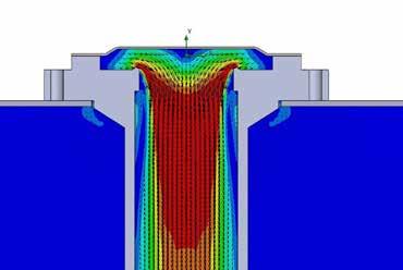
13 range La range of TURBO header tanks - Global immersion In global immersion header tanks, the diaphragm valve is fully immersed in the fluid. This feature ensures a particularly high yield. - With threaded stubs These ensure a perfectly rigid valve assembly and alignment. The valves used for these header tanks have threaded connections. - With plain stubs This solution allows for extremely quick and efficient valve assembly. - Alutank aluminium header tanks These lightweight header tanks are fully made according to customer requirements and are particularly easy to handle. The anodised aluminium provides particular resistance against weather agents whilst preventing oxidation. It also ensures clean compressed air supply. HEADER TANKS 13


14 header tanks HEADER TANKS GLOBAL IMMERSION HEADER TANKS INTEGRAL series PED 2014/68/EU HEADER TANKS WITH THREADED STUBS TF series PED 2014/68/EU HEADER TANKS WITH THREADED STUBS FOR STRAIGHT THROUGH VALVES TL series PED 2014/68/EU HEADER TANKS WITH PLAIN STUBS TD series PED 2014/68/EU STAINLESS STEEL HEADER TANKS XTF - INX series PED 2014/68/EU GLOBAL IMMERSION HEADER TANKS ALUTANK series PED 2014/68/EU DEPACKING HEADER TANKS PACK series PED 2014/68/EU CERTIFICATES COMPLIANT WITH THE 2014/68/EU - PED DIRECTIVES 14
15 how to order HEADER TANK MODEL GLOBAL IMMERSION = WITH THREADED STUBS = WITH PLAIN STUBS = ALUMINIUM = TANK DIAMETER 4 = 4 5 = 5 6 = 6 8 = 8 10 = = = 14 INTEGRAL TF - TL TD ALUTANK example INTEGRAL 6 P N10 P150 F G1 HEADER TANKS BUILT-IN PILOT = REMOTE PILOT = P M VALVE DIAMETER 1/2 = 10 3/4 = 20 1 = 25 1 ½" = 30 1 ½" = 35 1 ½" = 40 1 ½" = 45 2 = 50 2 = 54 2 = 55 2 ½" = 65 2 ½" = 71 3 = 75 3 = 80 3 ½" = 100 COIL VOLTAGE 24V/50-60Hz = V/50-60Hz = V/50-60Hz = VDC = 024DC N = NUMBER OF VALVES P = PITCH FLAT ENDS = F ONLY FOR INTEGRAL - ALUTANK series SHORT PLAIN OUTLET PIPE = LONG PLAIN OUTLET PIPE = LONG THREADED OUTLET PIPE = SHORT THREADED OUTLET PIPE = G1 G2 G3 G4 The code, INTEGRAL 6P N10P150FG1 represents a global immersion header tank of the Integral series, which has a 6 diameter (6), electric pilots installed (P), 10 (N10) x 1 valves (25) powered by a 24V 50Hz voltage (02450) and having a 150 mm pitch (P150). The bottoms are flat (F) and the outlet pipes are short and plain (G1). 15
16 4" integral series with ½" dn valves HEADER TANKS P min = 102 / B min = 55 For special versions of P min and B min, please contact our technical department DESCRIPTION TI010(N-V-T)P / TI010(N-V-T)M 1 Coil - Connector BH10 V## / V## 2 Screws - Washers TKITVTE06X18X4 3 Pilot unit Pilot cover Remote cover Diaphragm spring Diaphragm (N-V-T) TKISM010N Neoprene TKISM010V Viton TKISM010T Low temperature TI010(N-V-T)P V## / V## = 24 Vdc - 24 Vac Vac Vac TI010(N-V-T)M ½" SHORT PLAIN OUTLET PIPE = G1 LONG PLAIN OUTLET PIPE = G2 LONG THREADED OUTLET PIPE = G3 SHORT THREADED OUTLET PIPE = G4 16
17 5" integral series with ¾" dn valves GLOBAL IMMERSION HEADER TANKS P min = 120 / B min = 90 For special versions of P min and B min, please contact our technical department TI020(N-V-T)P DESCRIPTION TI020(N-V-T)P / TI020(N-V-T)M 1 Coil - Connector BH10 V## / V## 2 Screws - Washers TKITVTE06X18X4 3 Pilot unit Pilot cover Remote cover a Diaphragm spring Diaphragm (N-V-T) TKISM025N Neoprene TKISM025V Viton TKISM025T Low temperature V## / V## = 24 Vdc - 24 Vac Vac Vac TI020(N-V-T)M BRACKETS CS = COLLAR SA = HIGH SUPPORT A = 180 SM= MEDIUM SUPPORT A = 160 SB = LOW SUPPORT A = 95 ¾" SHORT PLAIN OUTLET PIPE = G1 LONG PLAIN OUTLET PIPE = G2 LONG THREADED OUTLET PIPE = G3 SHORT THREADED OUTLET PIPE = G4 17
18 5" integral series with 1" dn valves HEADER TANKS P min = 120 / B min = 90 For special versions of P min and B min, please contact our technical department DESCRIPTION TI025(N-V-T)P / TI025(N-V-T)M 1 Coil - Connector BH10 V## / V## 2 Screws - Washers TKITVTE06X18X4 3 Pilot unit Pilot cover Remote cover a Diaphragm spring Diaphragm (N-V-T) TKISM025N Neoprene TKISM025V Viton TKISM025T Low temperature TI025(N-V-T)P V## / V## = 24 Vdc - 24 Vac Vac Vac TI025(N-V-T)M BRACKETS CS = COLLAR SA = HIGH SUPPORT SM= MEDIUM SUPPORT SB = LOW SUPPORT A = 180 A = 160 A = 95 ¾" SHORT PLAIN OUTLET PIPE = G1 LONG PLAIN OUTLET PIPE = G2 LONG THREADED OUTLET PIPE = G3 SHORT THREADED OUTLET PIPE = G4 18
19 6" integral series with ¾ dn valves GLOBAL IMMERSION HEADER TANKS P min = 120 / B min = 90 For special versions of P min and B min, please contact our technical department DESCRIPTION TI020(N-V-T)P / TI020(N-V-T)M 1 Coil - Connector BH10 V## / V## 2 Screws - Washers TKITVTE06X18X4 3 Pilot unit Pilot cover Remote cover a Diaphragm spring TI020(N-V-T)P 6 Diaphragm (N-V-T) TKISM025N Neoprene TKISM025V Viton TKISM025T Low temperature V## / V## = 24 Vdc - 24 Vac Vac Vac TI020(N-V-T)M BRACKETS CS = COLLAR SA = HIGH SUPPORT SM= MEDIUM SUPPORT SB = LOW SUPPORT A = 200 A = 170 A = 109 ¾" SHORT PLAIN OUTLET PIPE = G1 LONG PLAIN OUTLET PIPE = G2 LONG THREADED OUTLET PIPE = G3 SHORT THREADED OUTLET PIPE = G4 19
20 6" integral series with 1" dn valves HEADER TANKS P min = 120 / B min = 90 For special versions of P min and B min, please contact our technical department DESCRIPTION TI025(N-V-T)P / TI025(N-V-T)M 1 Coil - Connector BH10 V## / V## 2 Screws - Washers TKITVTE06X18X4 3 Pilot unit Pilot cover Remote cover a Diaphragm spring Diaphragm (N-V-T) TKISM025N Neoprene TKISM025V Viton TKISM025T Low temperature TI025(N-V-T)P V## / V## = 24 Vdc - 24 Vac Vac Vac TI025(N-V-T)M BRACKETS CS = COLLAR SA = HIGH SUPPORT SM= MEDIUM SUPPORT SB = LOW SUPPORT A = 200 A = 170 A = 109 1" SHORT PLAIN OUTLET PIPE = G1 LONG PLAIN OUTLET PIPE = G2 LONG THREADED OUTLET PIPE = G3 SHORT THREADED OUTLET PIPE = G4 20
21 6" integral series with 1½" dn valves GLOBAL IMMERSION HEADER TANKS P min = 145 / B min = 100 For special versions of P min and B min, please contact our technical department DESCRIPTION TI030(N-V-T)P / TI030(N-V-T)M TI030(N-V-T)P 1 Coil - Connector BH10 V## / V## 2 Screws - Washers TKITVTE06X20X6 3 Pilot unit Pilot cover Remote cover Diaphragm spring TI030(N-V-T)M 7 Diaphragm (N-V-T) TKISM030N Neoprene TKISM030V Viton TKISM030T Low temperature V## / V## = 24 Vdc - 24 Vac Vac Vac BRACKETS CS = COLLAR SA = HIGH SUPPORT SM= MEDIUM SUPPORT SB = LOW SUPPORT A = 200 A = 170 A = 109 1½" SHORT PLAIN OUTLET PIPE = G1 LONG PLAIN OUTLET PIPE = G2 LONG THREADED OUTLET PIPE = G3 SHORT THREADED OUTLET PIPE = G4 21
22 6" integral series with 1½" dn valves HEADER TANKS P min = 145 / B min = 100 For special versions of P min and B min, please contact our technical department DESCRIPTION TI035(N-V-T)P / TI035(N-V-T)M 1 Coil - Connector BH10 V## / V## 2 Screws - Washers TKITVTE06X18X4 3 Pilot unit Pilot cover Remote cover Diaphragm spring bar bar Secondary diaphragm (N-V-T) TKISM010N Neoprene TKISM010V Viton TKISM010T Low temperature 8 Screws - Washers TKITVTE06X20X6 9 Cover Diaphragm spring Primary diaphragm (N-V-T) TKISM035N Neoprene TKISM035V Viton TKISM035T Low temperature V## / V## = 24 Vdc - 24 Vac Vac Vac BRACKETS CS = COLLAR SA = HIGH SUPPORT SM= MEDIUM SUPPORT SB = LOW SUPPORT A = 200 A = 170 A = 109 TI035(N-V-T)M TI035(N-V-T)P 1½" SHORT PLAIN OUTLET PIPE = G1 LONG PLAIN OUTLET PIPE = G2 LONG THREADED OUTLET PIPE = G3 SHORT THREADED OUTLET PIPE = G4 22
23 8" integral series with 1" dn valves GLOBAL IMMERSION HEADER TANKS P min = 120 / B min = 100 For special versions of P min and B min, please contact our technical department DESCRIPTION TI025(N-V-T)P / TI025(N-V-T)M 1 Coil - Connector BH10 V## / V## 2 Screws - Washers TKITVTE06X18X4 3 Pilot unit Pilot cover Remote cover a Diaphragm spring TI025(N-V-T)P 6 Diaphragm (N-V-T) TKISM025N Neoprene TKISM025V Viton TKISM025T Low temperature V## / V## = 24 Vdc - 24 Vac Vac Vac TI025(N-V-T)M BRACKETS CS = COLLAR SA = HIGH SUPPORT SM= MEDIUM SUPPORT SB = LOW SUPPORT A = 270 A = 210 A = 134 1" SHORT PLAIN OUTLET PIPE = G1 LONG PLAIN OUTLET PIPE = G2 LONG THREADED OUTLET PIPE = G3 SHORT THREADED OUTLET PIPE = G4 23
24 8" integral series with 1½" dn valves HEADER TANKS P min = 145 / B min = 100 For special versions of P min and B min, please contact our technical department DESCRIPTION TI030(N-V-T)P / TI030(N-V-T)M 1 Coil - Connector BH10 V## / V## 2 Screws - Washers TKITVTE06X20X6 3 Pilot unit Pilot cover Remote cover Diaphragm spring TI030(N-V-T)P 7 Diaphragm (N-V-T) TKISM030N Neoprene TKISM030V Viton TKISM030T Low temperature V## / V## = 24 Vdc - 24 Vac Vac Vac TI030(N-V-T)M BRACKETS CS = COLLAR SA = HIGH SUPPORT SM= MEDIUM SUPPORT SB = LOW SUPPORT A = 270 A = 210 A = 134 1½" SHORT PLAIN STUB = G1 LONG PLAIN STUB = G2 LONG THREADED STUB = G3 SHORT THREADED STUB = G4 24
25 8" integral series with 1½" dn valves GLOBAL IMMERSION HEADER TANKS P min = 145 / B min = 100 For special versions of P min and B min, please contact our technical department TI035(N-V-T)M TI035(N-V-T)P DESCRIPTION TI035(N-V-T)P / TI035(N-V-T)M 1 Coil - Connector BH10 V## / V## 2 Screws - Washers TKITVTE06X18X4 3 Pilot unit Pilot cover Remote cover Diaphragm spring Secondary Diaphragm (N-V-T) TKISM010N Neoprene TKISM010V Viton TKISM010T Low temperature 8 Screws - Washers TKITVTE06X20X6 9 Cover Diaphragm spring Primary diaphragm (N-V-T) V## / V## = 24 Vdc - 24 Vac Vac Vac TKISM035N Neoprene TKISM035V Viton TKISM035T Low temperature BRACKETS CS = COLLAR SA = HIGH SUPPORT SM= MEDIUM SUPPORT SB = LOW SUPPORT A = 270 A = 210 A = 134 1½" SHORT PLAIN OUTLET PIPE = G1 LONG PLAIN OUTLET PIPE = G2 LONG THREADED OUTLET PIPE = G3 SHORT THREADED OUTLET PIPE = G4 25
26 8" integral series with 1½" dn valves HEADER TANKS P min = 160 / B min = 100 For special versions of P min and B min, please contact our technical department DESCRIPTION TI040(N-V-T)P / TI040(N-V-T)M 1 Coil - Connector BH10 V## / V## 2 Screws - Washers TKITVTE06X20X4 3 Pilot unit Pilot cover Remote cover Secondary Diaphragm (N-V-T) TKISM025N Neoprene TKISM025V Viton TKISM025T Low temperature 6a Diaphragm spring Screws - Washers TKITVTE08X20X6 8 Cover Diaphragm spring Primary diaphragm (N-V-T) TKISM040N Neoprene TKISM040V Viton TKISM040T Low temperature V## / V## = 24 Vdc - 24 Vac Vac Vac TI040(N-V-T)M TI040(N-V-T)P BRACKETS CS = COLLAR SA = HIGH SUPPORT SM= MEDIUM SUPPORT SB = LOW SUPPORT A = 270 A = 210 A = 134 1½" SHORT PLAIN OUTLET PIPE = G1 LONG PLAIN OUTLET PIPE = G2 LONG THREADED OUTLET PIPE = G3 SHORT THREADED OUTLET PIPE = G4 26
27 8" integral series with 1½" dn valves GLOBAL IMMERSION HEADER TANKS P min = 160 / B min = 100 For special versions of P min and B min, please contact our technical department TI045(N-V-T)M TI045(N-V-T)P DESCRIPTION TI045(N-V-T)P / TI045(N-V-T)M 1 Coil - Connector BH10 V## / V## 2 Screws - Washers TKITVTE06X18X4 3 Pilot unit Pilot cover Remote cover Diaphragm spring Secondary diaphragm (N-V-T) TKISM010N Neoprene TKISM010V Viton TKISM010T Low temperature 8 Screws - Washers TKITVTE08X20X6 9 Cover Diaphragm spring Primary diaphragm (N-V-T) V## / V## = 24 Vdc - 24 Vac Vac Vac TKISM045N Neoprene TKISM045V Viton TKISM045T Low temperature BRACKETS CS = COLLAR SA = HIGH SUPPORT SM= MEDIUM SUPPORT SB = LOW SUPPORT A = 270 A = 210 A = 134 1½" SHORT PLAIN OUTLET PIPE = G1 LONG PLAIN OUTLET PIPE = G2 LONG THREADED OUTLET PIPE = G3 SHORT THREADED OUTLET PIPE = G4 27
28 10" integral series with 1½" dn valves HEADER TANKS P min = 170 / B min = 100 For special versions of P min and B min, please contact our technical department DESCRIPTION TI040(N-V-T)P / TI040(N-V-T)M 1 Coil - Connector BH10 V## / V## 2 Screws - Washers TKITVTE06X20X4 3 Pilot unit Pilot cover Remote cover Secondary diaphragm (N-V-T) TKISM025N Neoprene TKISM025V Viton TKISM025T Low temperature 6a Diaphragm spring Screws - Washers TKITVTE08X20X6 8 Cover Diaphragm spring Primary Diaphragm (N-V-T) TKISM040N Neoprene TKISM040V Viton TKISM040T Low temperature V## / V## = 24 Vdc - 24 Vac Vac Vac TI040(N-V-T)M TI040(N-V-T)P BRACKETS CS = COLLAR SA = HIGH SUPPORT SB = LOW SUPPORT A = 273 A = 161 1½" SHORT PLAIN OUTLET PIPE = G1 LONG PLAIN OUTLET PIPE = G2 LONG THREADED OUTLET PIPE = G3 SHORT THREADED OUTLET PIPE = G4 28
29 10" integral series with 2" dn valves GLOBAL IMMERSION HEADER TANKS P min = 185 / B min = 115 For special versions of P min and B min, please contact our technical department TI050(N-V-T)M TI050(N-V-T)P DESCRIPTION TI050(N-V-T)P / TI050(N-V-T)M 1 Coil - Connector BH10 V## / V## 2 Screws - Washers TKITVTE06X20X4 3 Pilot unit Pilot cover Remote cover Secondary diaphragm (N-V-T) TKISM025N Neoprene TKISM025V Viton TKISM025T Low temperature 6a Diaphragm spring Screws - Washers TKITVTE10X25X6 8 Cover Diaphragm spring Primary Diaphragm (N-V-T) V## / V## = 24 Vdc - 24 Vac Vac Vac TKISM050N Neoprene TKISM050V Viton TKISM050T Low temperature BRACKETS CS = COLLAR SA = HIGH SUPPORT SB = LOW SUPPORT A = 273 A = 161 2" SHORT PLAIN OUTLET PIPE = G1 LONG PLAIN OUTLET PIPE = G2 LONG THREADED OUTLET PIPE = G3 SHORT THREADED OUTLET PIPE = G4 G5(*) Used for coupling with PD55 bulk connectors via SA10 bracket 29
30 10" integral series with 2½" dn valves HEADER TANKS P min = 185 / B min = 120 For special versions of P min and B min, please contact our technical department DESCRIPTION TI060(N-V-T)P / TI060(N-V-T)M 1 Coil - Connector BH10 V## / V## 2 Screws - Washers TKITVTE06X20X4 3 Pilot unit Pilot cover Remote cover Secondary diaphragm (N-V-T) TKISM025N Neoprene TKISM025V Viton TKISM025T Low temperature 6a Diaphragm spring Screws - Washers TKITVTE10X25X6 8 Cover Diaphragm spring Primary Diaphragm (N-V-T) TKISM060N Neoprene TKISM060V Viton TKISM060T Low temperature V## / V## = 24 Vdc - 24 Vac Vac Vac TI060(N-V-T)M TI060(N-V-T)P BRACKETS CS = COLLAR SA = HIGH SUPPORT SB = LOW SUPPORT A = 273 A = 161 2½" SHORT PLAIN OUTLET PIPE = G1 LONG PLAIN OUTLET PIPE = G2 LONG THREADED OUTLET PIPE = G3 SHORT THREADED OUTLET PIPE = G4 30
31 12" integral series with 2½" dn valves GLOBAL IMMERSION HEADER TANKS P min = 185 / B min = 120 For special versions of P min and B min, please contact our technical department TI071(N-V-T)M TI071(N-V-T)P DESCRIPTION TI071(N-V-T)P / TI071(N-V-T)M 1 Coil - Connector BH10 V## / V## 2 Screws - Washers TKITVTE06X20X4 3 Pilot unit Pilot cover Remote cover Secondary diaphragm (N-V-T) TKISM025N Neoprene TKISM025V Viton TKISM025T Low temperature 6a Diaphragm spring Screws - Washers TKITVTE10X25X6 8 Cover Diaphragm spring Primary Diaphragm (N-V-T) V## / V## = 24 Vdc - 24 Vac Vac Vac TKISM080N Neoprene TKISM080V Viton TKISM080T Low temperature 2½" The customer is responsible for the size and type of outlet pipe 31
32 12" integral series with 3" dn valves HEADER TANKS P min = 215 / B min = 125 For special versions of P min and B min, please contact our technical department DESCRIPTION TI075(N-V-T)P / TI075(N-V-T)M 1 Coil - Connector BH10 V## / V## 2 Screws - Washers TKITVTE06X20X4 3 Pilot unit Pilot cover Remote cover Secondary diaphragm (N-V-T) TKISM025N Neoprene TKISM025V Viton TKISM025T Low temperature 6a Diaphragm spring Screws - Washers TKITVTE10X25X6 8 Cover Diaphragm spring Primary Diaphragm (N-V-T) V## / V## = 24 Vdc - 24 Vac Vac Vac TKISM075N Neoprene TKISM075V Viton TKISM075T Low temperature TI075(N-V-T)M TI075(N-V-T)P 3" The customer is responsible for the size and type of outlet pipe 32
33 12" integral series with 3" dn valves GLOBAL IMMERSION HEADER TANKS P min = 215 / B min = 125 For special versions of P min and B min, please contact our technical department TI080(N-V-T)M TI080(N-V-T)P DESCRIPTION TI080(N-V-T)P / TI080(N-V-T)M 1 Coil - Connector BH10 V## / V## 2 Screws - Washers TKITVTE06X20X4 3 Pilot unit Pilot cover Remote cover Secondary diaphragm (N-V-T) TKISM025N Neoprene TKISM025V Viton TKISM025T Low temperature 6a Diaphragm spring Screws - Washers TKITVTE10X25X6 8 Cover Diaphragm spring Primary Diaphragm (N-V-T) V## / V## = 24 Vdc - 24 Vac Vac Vac TKISM080N Neoprene TKISM080V Viton TKISM080T Low temperature 3" The customer is responsible for the size and type of outlet pipe 33
34 14" integral series with 3" dn valves HEADER TANKS P min = 215 / B min = 125 For special versions of P min and B min, please contact our technical department TI075(N-V-T)M TI075(N-V-T)P DESCRIPTION TI075(N-V-T)P / TI075(N-V-T)M 1 Coil - Connector BH10 V## / V## 2 Screws - Washers TKITVTE06X20X4 3 Pilot unit Pilot cover Remote cover Secondary diaphragm (N-V-T) TKISM025N Neoprene TKISM025V Viton TKISM025T Low temperature 6a Diaphragm spring Screws - Washers TKITVTE10X25X6 8 Cover Diaphragm spring Primary Diaphragm (N-V-T) V## / V## = 24 Vdc - 24 Vac Vac Vac TKISM075N Neoprene TKISM075V Viton TKISM075T Low temperature 3" The customer is responsible for the size and type of outlet pipe 34
35 14" integral series with 3" dn valves GLOBAL IMMERSION HEADER TANKS P min = 215 / B min = 125 For special versions of P min and B min, please contact our technical department TI080(N-V-T)M TI080(N-V-T)P DESCRIPTION TI080(N-V-T)P / TI080(N-V-T)M 1 Coil - Connector BH10 V## / V## 2 Screws - Washers TKITVTE06X20X4 3 Pilot unit Pilot cover Remote cover Secondary diaphragm (N-V-T) TKISM025N Neoprene TKISM025V Viton TKISM025T Low temperature 6a Diaphragm spring Screws - Washers TKITVTE10X25X6 8 Cover Diaphragm spring Primary Diaphragm (N-V-T) V## / V## = 24 Vdc - 24 Vac Vac Vac TKISM080N Neoprene TKISM080V Viton TKISM080T Low temperature 3" The customer is responsible for the size and type of outlet pipe 35
36 14" Integral series with 3½" Dn valves HEADER TANKS P min = 225 / B min = 125 For special versions of P min and B min, please contact our technical department DESCRIPTION TI0100(N-V-T)P / TI0100(N-V-T)M 1 Coil - Connector BH10 V## / V## 2 Screws - Washers TKITVTE06X20X4 3 Pilot unit Pilot cover Remote cover Secondary diaphragm (N-V-T) TKISM025N Neoprene TKISM025V Viton TKISM025T Low temperature 6a Diaphragm spring Screws - Washers TKITVTE10X25X6 8 Cover Diaphragm spring Primary Diaphragm (N-V-T) V## / V## = 24 Vdc - 24 Vac Vac Vac TKISM0100N Neoprene TKISM0100V Viton TKISM0100T Low temperature TI0100(N-V-T)M TI0100(N-V-T)P 3½" The customer is responsible for the size and type of outlet pipe 36


37 RESEARCH AND DEVELOPMENT 37
38 Dn tf series HEADER TANKS L = Px(N-1)+2A+2B P = Distance between the valves N = Number of valves For special versions of P min and B min, please contact our technical department Ø (Nom.) Ø(out) mm ØE B(min) ØF H M R Z(±) S(±) P(min) ¾ ¾ ½" ½" ½" 55 1 ½" ½" ½" 55 1 ½" ½" ½" 70 1 ½" ½" ½" DESCRIPTION TF020(N-V-T)P / TF020(N-V-T)M TF025(N-V-T)P / TF025(N-V-T)M 1 Coil + Connector BH10 V## / V## BH10 V## / V## 2 Screws + Washers TKITVTE06X20X4 TKITVTE06X20X4 3 Pilot unit Pilot cover Remote cover Diaphragm (N-V-T) TKISM025N Neoprene TKISM025V Viton TKISM025T Low temperature TKISM025N Neoprene TKISM025V Viton TKISM025T Low temperature TF020(N-V-T)M TF025(N-V-T)M 6a Diaphragm spring Valve body V## / V## = 24 Vdc - 24 Vac Vac Vac TF020(N-V-T)P TF025(N-V-T)P 38
39 Dn tf series TF040(N-V-T)P TF055(N-V-T)P TF065(N-V-T)P TF085(N-V-T)P TF040(N-V-T)M TF055(N-V-T)M TF065(N-V-T)M TF085(N-V-T)M HEADER HEADER TANKS TANKS XXXXXXXXXXXXXXXXXX WITH THREADED STUBS DESCRIPTION TF040(N-V-T)P TF055(N-V-T)P TF065(N-V-T)P TF085(N-V-T)P TF040(N-V-T)M TF055(N-V-T)M TF065(N-V-T)M TF085(N-V-T)M 1 Coil + Connector BH10 V## / V## BH10 V## / V## BH10 V## / V## BH10 V## / V## 2 Screws + Washers TKITVTE06X20X4 TKITVTE06X20X4 TKITVTE06X20X4 TKITVTE06X20X4 3 Pilot unit Pilot cover Remote cover Secondary diaphragm (N-V-T) TKISM025N Neoprene TKISM025V Viton TKISM025T Low temperature TKISM025N Neoprene TKISM025V Viton TKISM025T Low temperature TKISM025N Neoprene TKISM025V Viton TKISM025T Low temperature TKISM025N Neoprene TKISM025V Viton TKISM025T Low temperature 6a Diaphragm spring Screws + Washers TKITVTE08X20X6 TKITVTE10X25X6 TKITVTE10X25X6 TKITVTE10X30X8 8 Cover Diaphragm spring TKISM040N Neoprene TKISM055N Neoprene TKISM065N Neoprene Primary diaphragm TKISM040V Viton TKISM055V Viton TKISM065V Viton 10 (N-V-T) TKISM040T Low TKISM055T Low TKISM065T Low temperature temperature temperature 11 Valve body TKISM085N Neoprene TKISM085V Viton TKISM085T Low temperature DESCRIPTION TF045(N-V-T)P / TF045(N-V-T)M 1 Coil - Connector BH10 V## / V## 2 Screws - Washers TKITVTE06X18X4 3 Pilot unit Pilot cover Remote cover Diaphragm spring Secondary diaphragm (N-V-T) TKISM010N Neoprene TKISM010V Viton TKISM010T Low temperature 8 Screws - Washers TKITVTE08X20X6 9 Cover Diaphragm spring Primary Diaphragm (N-V-T) 12 Valve body TKISM045N Neoprene TKISM045V Viton TKISM045T Low temperature V## / V## = 24 Vdc - 24 Vac Vac Vac TF045(N-V-T)M TF045(N-V-T)P TFP version with built-in pilot / TFM version with remote pilot 39
40 6-8 tl series HEADER TANKS L = Px(N-1)+2A+2B P = Distance between the valves N = Number of valves For special versions of P min and B min, please contact our technical department Ø Ø(out) mm ØE A B(min) ØF H M R Z(±) S(±) P(min) Brackets ¼" S S ½" S " AIR CANNON 2. FILTER WALL 3. ASSEMBLY HOLE MIN 56 mm 4. 1" STRAIGHT THROUGH VALVE 1. 1 ½" AIR CANNON 2. FILTER WALL 3. ASSEMBLY HOLE MIN 72 mm 4. 1½" STRAIGHT THROUGH VALVE 40
41 TL025(N-V-T)P tl series / Part List DESCRIPTION TL025(N-V-T)P / TL025(N-V-T)M TL025(N-V-T)M 1 Coil - Connector BH10 V## / V## 2 Screws - Washers TKITVTE06X20X4 3 Pilot unit Pilot cover Remote cover a Diaphragm spring TKISM010N Neoprene 6 Diaphragm (N-V-T) TKISM010V Viton TKISM010T Low temperature 7 Valve body Seal Lock nut Conical seal Retaining ring Hose Clamp High Nut DESCRIPTION TL030(N-V-T)P / TL030(N-V-T)M 1 Coil - Connector BH10 V## / V## 2 Screws - Washers TKITVTE06X20X6 TL030(N-V-T)M TL030(N-V-T)P 3 Pilot unit Pilot cover Remote cover a Diaphragm spring TKISM030N Neoprene 6 Diaphragm (N-V-T) TKISM030V Viton TKISM030T Low temperature 7 Valve body Seal Lock nut Conical seal Retaining ring Hose Clamp High Nut DESCRIPTION TL035(N-V-T)P / TL035(N-V-T)M 1 Coil - Connector BH10 V## / V## TL035(N-V-T)P 2 Screws - Washers TKITVTE06X18X4 3 Pilot unit TL035(N-V-T)M 4 Pilot cover Remote cover Diaphragm spring V## / V## = 24 Vdc - 24 Vac Vac Vac 7 Secondary diaphragm (N-V-T) TKISM010N Neoprene TKISM010V Viton TKISM010T Low temperature 8 Screws - Washers TKITVTE06X20X6 9 Cover Diaphragm spring Primary Diaphragm (N-V-T) 12 Valve body Seal Lock nut Conical seal Retaining ring Hose clamp high nut TKISM035N Neoprene TKISM035V Viton TKISM035T Low temperature HEADER TANKS WITH HEADER THREADED TANKS STUBS FOR STRAIGHT THROUGH XXXXXXXXXXXXXXXXXX VALVES 41
42 dn td series HEADER TANKS L = Px(N-1)+2A+2B P = Distance between the valves N = Number of valves For special versions of P min and B min, please contact our technical department Ø (NOM) Ø(out) mm ØE A B(min) ØF H M Z(±) S(±) P(min) ¾ ¾ ½" ½" ½" ½" ½" ½"
43 dn td series DESCRIPTION TD020(N-V-T)P / TD020(N-V-T)M TD025(N-V-T)P / TD025(N-V-T)M 1 Coil - Connector BH10 V## / V## BH10 V## / V## 2 Screws - Washers TKITVTE06X18X4 TKITVTE06X18X4 3 Pilot unit Pilot cover Remote cover Diaphragm (N-V-T) TKISM025N Neoprene TKISM025V Viton TKISM025T Low temperature 6a Diaphragm spring Valve body Conical seal Retaining ring Hose clamp high nut V## / V## = 24 Vdc - 24 Vac Vac Vac TKISM025N Neoprene TKISM025V Viton TKISM025T Low temperature TD020(N-V-T)M TD025(N-V-T)M HEADER TANKS TANKS XXXXXXXXXXXXXXXXXX WITH PLAIN STUBS DESCRIPTION TD040(N-V-T)P / TL040(N-V-T)M TD045(N-V-T)P / TD045(N-V-T)M 1 Coil - Connector BH10 V## / V## BH10 V## / V## 2 Screws - Washers TKITVTE06X20X4 TKITVTE06X18X4 3 Pilot unit Pilot cover Remote cover Secondary diaphragm (N-V-T) TKISM025N Neoprene TKISM025V Viton TKISM025T Low temperature TKISM010N Neoprene TKISM010V Viton TKISM010T Low temperature 6a Diaphragm spring Screws - Washers TKITVTE08X20X6 TKITVTE08X20X6 8 Cover Diaphragm spring Primary Diaphragm (N-V-T) TKISM040N Neoprene TKISM040V Viton TKISM040T Low temperature 11 Valve body Conical seal Retaining ring Hose clamp high nut V## / V## = 24 Vdc - 24 Vac Vac Vac TKISM045N Neoprene TKISM045V Viton TKISM045T Low temperature TD040(N-V-T)M TD020(N-V-T)P TD025(N-V-T)P TD040(N-V-T)P TD045(N-V-T)P TD045(N-V-T)M 43
44 xtf Series dn with threaded stumps STAINLESS STEEL HEADER TANKS L = Px(N-1)+2A+2B P = Distance between valves N = Number of valves For special versions of P min and B min, please contact our technical department Ø (NOM) Ø(out) mm ØE B(min) ØF H M R Z(±) S(±) P(min) ¾ ½" ¾ ½" ½" ½" 55 1 ½" ½" ½" 65 1 ½" ½" 55 1 ½" ½" ½" 70 1 ½" Operating temperature: -50 C/+200 C dn inx integral series - global immersion header tanks Please contact our technical department for the dimensions Operating temperature: -50 C/+200 C 44


45 range BRACKETS TANK DIAMETER BRACKET MODEL BRACKET CODE A (mm) B (mm) H mm S (mm) Weight (kg) 5 (Ø 141.3) 6 (Ø 168.3) 8 (Ø 219.1) 10 (Ø 273) Low bracket SB Medium bracket SM High bracket SA Low bracket SB Medium bracket SM High bracket SA TL series bracket S TL series bracket S Low bracket SB Medium bracket SM High bracket SA TL series bracket S Low bracket SB High bracket SA For special brackets, please contact our technical department u-bolts TANK DIAMETER ØA (mm) B (mm) C (mm) D (mm) E (mm) 4 (Ø 114.3) M10 5 (Ø 141.3) M10 6 (Ø 168.3) M16 8 (Ø 219.1) M16 U-Bolts are available in galvanised steel or stainless steel, on request 45
46 6 alutank series with 1 Dn valves HEADER TANKS TECHNICAL FEATURES Tank body Extruded anodised aluminium Ends Die-cast aluminium Air cannons Galvanised steel O-Ring NBR Operating temperature -20 C +80 C Operating pressure bar bar Low temperature version - 40 C +80 C 6 bar PRESSURE B min.= 51 P min.= 91 8 bar PRESSURE B min.= 61 P min.= 121 (Aluminium air cannons) For special versions of P min and B min, please contact our technical department DESCRIPTION TS025(N-V-T)P / TS025(N-V-T)M 1 Coil - Connector BH10 V## / V## 2 Screws - Washers TKITVTE06X20X4 3 Pilot unit Pilot cover Remote cover Diaphragm (N-V-T) TKISM025N Neoprene TKISM025V Viton TKISM025T Low temperature 6a Diaphragm spring Screws - Washers TKITVTE06X16X4 8 Valve body O-R gasket V## / V## = 24 Vdc - 24 Vac Vac Vac TS025(N-V-T)M TS025(N-V-T)P DETAIL OF BOTTOM DIMENSIONS AND FIXING Standard Without Brackets 1" SHORT PLAIN OUTLET PIPE = G1 LONG PLAIN OUTLET PIPE = G2 LONG THREADED OUTLET PIPE = G3 SHORT THREADED OUTLET PIPE = G4 46
47 6" alutank series with 1½" dn valves 6 bar PRESSURE B min.= 58 P min.= bar PRESSURE B min.= 73 P min.= 145 TECHNICAL FEATURES Tank body Extruded anodised aluminium Ends Die-cast aluminium Air cannons Galvanised steel O-Ring NBR Operating temperature -20 C +80 C Operating pressure bar bar Low temperature version - 40 C +80 C (Aluminium air cannons) ALUMINIUM GLOBAL IMMERSION HEADER TANKS For special versions of P min and B min, please contact our technical department TS030(N-V-T)M TS030(N-V-T)P DESCRIPTION TS030(N-V-T)P / TS030(N-V-T)M 1 Coil - Connector BH10 V## / V## 2 Screws - Washers TKITVTE06X20X6 3 Pilot unit Pilot cover Remote cover Diaphragm spring Diaphragm (N-V-T) TKISM030N Neoprene TKISM030V Viton TKISM030T Low temperature 8 Screws - Washers TKITVTE06X20X2 9 Valve body O-R gasket V## / V## = 24 Vdc - 24 Vac Vac Vac DETAIL OF BOTTOM DIMENSIONS AND FIXING Standard Without Brackets 1½" SHORT PLAIN OUTLET PIPE = G1 LONG PLAIN OUTLET PIPE = G2 LONG THREADED OUTLET PIPE = G3 SHORT THREADED OUTLET PIPE = G4 47
48 6" alutank series with 1½" dn valves HEADER TANKS 6 bar PRESSURE B min.= 58 P min.= bar PRESSURE B min.= 73 P min.= 145 TECHNICAL FEATURES Tank body Extruded anodised aluminium Ends Die-cast aluminium Air cannons Galvanised steel O-Ring NBR Operating temperature -20 C +80 C Operating pressure bar bar Low temperature version - 40 C +80 C (Aluminium air cannons) For special versions of P min and B min, please contact our technical department DESCRIPTION TS035(N-V-T)P / TS035(N-V-T)M 1 Coil - Connector BH10 V## / V## 2 Screws - Washers TKITVTE06X18X4 3 Pilot unit Pilot cover Remote cover Diaphragm spring Secondary diaphragm TKISM010N Neoprene TKISM010V Viton (N-V-T) TKISM010T Low temperature TS035(N-V-T)M 8 Screws - Washers TKITVTE06X20X6 9 Cover Diaphragm spring Primary Diaphragm TKISM035N Neoprene 11 TKISM035V Viton (N-V-T) TKISM035T Low temperature 12 Screws - Washers TKITVTE08X20X2 13 Valve body O-R gasket V## / V## = 24 Vdc - 24 Vac Vac Vac TS035(N-V-T)P DETAIL OF BOTTOM DIMENSIONS AND FIXING Standard Without Brackets 1½" SHORT PLAIN OUTLET PIPE = G1 LONG PLAIN OUTLET PIPE = G2 LONG THREADED OUTLET PIPE = G3 SHORT THREADED OUTLET PIPE = G4 48
49 8 alutank series with 1 dn valves TECHNICAL FEATURES Tank body Extruded anodised aluminium Ends Die-cast aluminium Air cannons Galvanised steel O-Ring NBR Operating temperature -20 C +80 C Operating pressure bar bar Low temperature version - 40 C +80 C ALUMINIUM HEADER HEADER TANKS TANKS WITH XXXXXXXXXXXXXXXXXX GLOBAL IMMERSION (Aluminium air cannons) Please contact our technical department for P min and B min values TS025(N-V-T)M TS025(N-V-T)P DESCRIPTION TS025(N-V-T)P / TS025(N-V-T)M 1 Coil - Connector BH10 V## / V## 2 Screws - Washers TKITVTE06X20X4 3 Pilot unit Pilot cover Remote cover a Diaphragm spring Diaphragm (N-V-T) TKISM025N Neoprene TKISM025V Viton TKISM0250T Low temperature 7 Screws - Washers TKITVTE06X16X4 8 Valve body O-R gasket V## / V## = 24 Vdc - 24 Vac Vac Vac BOTTOM DIMENSIONS 1" SHORT PLAIN OUTLET PIPE = G1 LONG PLAIN OUTLET PIPE = G2 LONG THREADED OUTLET PIPE = G3 SHORT THREADED OUTLET PIPE = G4 49
50 8" alutank series with 1½" dn valves HEADER TANKS TECHNICAL FEATURES Tank body Extruded anodised aluminium Ends Die-cast aluminium Air cannons Galvanised steel O-Ring NBR Operating temperature -20 C +80 C Operating pressure bar bar Low temperature version - 40 C +80 C (Aluminium air cannons) Please contact our technical department for P min and B min values DESCRIPTION TS030(N-V-T)P / TS030(N-V-T)M 1 Coil - Connector BH10 V## / V## 2 Screws - Washers TKITVTE06X20X6 3 Pilot unit Pilot cover Remote cover Diaphragm spring Diaphragm (N-V-T) TKISM030N Neoprene TKISM030V Viton TKISM030T Low temperature 8 Screws - Washers TKITVTE06X20X2 9 Valve body O-R gasket V## / V## = 24 Vdc - 24 Vac Vac Vac TS030(N-V-T)M TS030(N-V-T)P BOTTOM DIMENSIONS 1½" SHORT PLAIN OUTLET PIPE = G1 LONG PLAIN OUTLET PIPE = G2 LONG THREADED OUTLET PIPE = G3 SHORT THREADED OUTLET PIPE = G4 50
51 8" alutank series with 1½" dn valves TECHNICAL FEATURES Tank body Extruded anodised aluminium Ends Die-cast aluminium Air cannons Galvanised steel O-Ring NBR Operating temperature -20 C +80 C Operating pressure bar bar Low temperature version - 40 C +80 C (Aluminium air cannons) ALUMINIUM HEADER GLOBAL TANKS IMMERSION HEADER TANKS XXXXXXXXXXXXXXXXXX Please contact our technical department for P min and B min values TS035(N-V-T)M TS035(N-V-T)P DESCRIPTION TS035(N-V-T)P / TS035(N-V-T)M 1 Coil - Connector BH10 V## / V## 2 Screws - Washers TKITVTE06X18X4 3 Pilot unit Pilot cover Remote cover Diaphragm spring Secondary diaphragm (N-V-T) TKISM010N Neoprene TKISM010V Viton TKISM010T Low temperature 8 Screws - Washers TKITVTE06X20X6 9 Cover Diaphragm spring Primary Diaphragm (N-V-T) TKISM035N Neoprene TKISM035V Viton TKISM035T Low temperature 12 Screws - Washers TKITVTE08X20X2 13 Valve body O-R gasket V## / V## = 24 Vdc - 24 Vac Vac Vac BOTTOM DIMENSIONS 1½" SHORT PLAIN OUTLET PIPE = G1 LONG PLAIN OUTLET PIPE = G2 LONG THREADED OUTLET PIPE = G3 SHORT THREADED OUTLET PIPE = G4 51
52 8 alutank series with 2 dn valves HEADER TANKS TECHNICAL FEATURES Tank body Extruded anodised aluminium Ends Die-cast aluminium Air cannons Galvanised steel O-Ring NBR Operating temperature -20 C +80 C Operating pressure bar bar Low temperature version - 40 C +80 C (Aluminium air cannons) Please contact our technical department for P min and B min values DESCRIPTION TS050(N-V-T)P / TS050(N-V-T)M 1 Coil - Connector BH10 V## / V## 2 Screws - Washers TKITVTE06X20X4 3 Pilot unit Pilot cover Remote cover a Diaphragm spring Secondary diaphragm (N-V-T) TKISM025N Neoprene TKISM025V Viton TKISM025T Low temperature 7 Screws - Washers TKITVTE10X25X6 8 Cover Diaphragm spring Primary Diaphragm (N-V-T) 11 Valve body O-R gasket TKISM050N Neoprene TKISM050V Viton TKISM050T Low temperature TS050(N-V-T)M TS050(N-V-T)P BOTTOM DIMENSIONS V## / V## = 24 Vdc - 24 Vac Vac Vac 2" SHORT PLAIN OUTLET PIPE = G1 LONG PLAIN OUTLET PIPE = G2 LONG THREADED OUTLET PIPE = G3 SHORT THREADED OUTLET PIPE = G4 52
53 6 alutank series with 1 dn valves TM025(N-V-T)P P min = 120 / B min = 70 For special versions of P min and B min, please contact our technical department DESCRIPTION TM025(N-V-T)P / TM025(N-V-T)M 1 Coil - Connector BH10 V## / V## 2 Screws - Washers TKITVTE06X20X4 3 Pilot unit Pilot cover Remote cover a Diaphragm spring Diaphragm (N-V-T) TKISM025N Neoprene TKISM025V Viton TKISM025T Low temperature 7 Valve body O-R gasket Screws - Washers TKITVTE08X25X4 10 Seal Lock nut Conical seal Retaining ring Hose Clamp High Nut V## / V## = 24 Vdc - 24 Vac Vac Vac TECHNICAL FEATURES Tank body Extruded anodised aluminium Ends Aluminium Air cannons Galvanised steel O-Ring NBR Operating temperature -20 C +80 C Operating pressure bar bar N.B. configuration for low temperature - 40 C +80 C 1. 1" AIR CANNON 2. FILTER WALL 3. HOLE ON WALL MIN 56 mm 4. 1" STRAIGHT THROUGH VALVE ALUMINIUM HEADER TANKS WITH STRAIGHT XXXXXXXXXXXXXXXXXX THROUGH VALVES TM025(N-V-T)M 1. 1" AIR CANNON 2. FILTER WALL 3. HOLE ON WALL MIN 56 mm 4. 1" STRAIGHT THROUGH VALVE 53
54 8 alutank series with 1 1½ Dn valves HEADER TANKS TECHNICAL FEATURES Tank body Extruded anodised aluminium Ends Aluminium Air cannons Galvanised steel O-Ring NBR Operating temperature -20 C +80 C Operating pressure bar bar Configuration for low temperature - 40 C +80 C Please contact our technical department for P min and B min values 1. 1" AIR CANNON 2. FILTER WALL 3. HOLE ON WALL MIN 56 mm 4. 1" STRAIGHT THROUGH VALVE EFDM25/EFDP ½" AIR CANNON 2. FILTER WALL 3. HOLE ON WALL MIN 72 mm 4. 1½" STRAIGHT THROUGH VALVE EFDM30/EFDP ½" AIR CANNON 2. FILTER WALL 3. HOLE ON WALL MIN 72 mm 4. 1½" STRAIGHT THROUGH VALVE EFDM35/EFDP35 54
55 8 alutank series with 1 1½ dn valves TM025(N-V-T)P TM025(N-V-T)M TM030(N-V-T)P TM030(N-V-T)M TM035(N-V-T)P TM035(N-V-T)M DESCRIPTION TM025(N-V-T)P / TM025(N-V-T)M 1 Coil - Connector BH10 V## / V## 2 Screws - Washers TKITVTE06X20X4 3 Pilot unit Pilot cover Remote cover a Diaphragm spring Diaphragm (N-V-T) TKISM025N Neoprene TKISM025V Viton TKISM025T Low temperature 7 Valve body O-R gasket Screws - Washers TKITVTE08X25X4 10 Seal Lock nut Conical seal Retaining ring Hose clamp high nut DESCRIPTION TM030(N-V-T)P / TM030(N-V-T)M 1 Coil - Connector BH10 V## / V## 2 Screws - Washers TKITVTE06X20X6 3 Pilot unit Pilot cover Remote cover Diaphragm spring Diaphragm (N-V-T) TKISM030N Neoprene TKISM030V Viton TKISM030T Low temperature 8 Valve body O-R gasket Screws - Washers TKITVTE10X25X4 11 Seal Lock nut Conical seal Retaining ring Hose clamp high nut DESCRIPTION TM035(N-V-T)P / TM035(N-V-T)M 1 Coil - Connector BH10 V## / V## 2 Screws - Washers TKITVTE06X18X4 3 Pilot unit Pilot cover Remote cover Diaphragm spring Secondary Diaphragm (N-V-T) TKISM010N Neoprene TKISM010V Viton TKISM010T Low temperature 8 Screws - Washers TKITVTE06X20X6 9 Cover Diaphragm spring Primary Diaphragm (N-V-T) TKISM035N Neoprene TKISM035V Viton TKISM035T Low temperature 12 Valve body O-R gasket Screws - Washers TKITVTE10X25X4 15 Seal Lock nut Conical seal Retaining ring Hose clamp high nut V## / V## = 24 Vdc - 24 Vac Vac Vac ALUMINIUM HEADER TANKS WITH STRAIGHT XXXXXXXXXXXXXXXXXX THROUGH VALVES 55

 124 100 1 90 73 38 368 280 160 13 ½ 250 PACK 25 895 219.")
 214 185 2 198")
56 pack series DEPACKING HEADER TANKS Model A ØB C E ØF G H I L M N ØO Ø P Q PACK ( 5 ) ¾ ½ 250 PACK ( 6 ) ½ 250 PACK ( 8 ) ½" ½ 350 PACK ( 10 ) ½ 350 PACK ( 12 ) ½" ½
57 TS series CODE AND TECHNICAL FEATURES TS 25 P100 N10 D10 L150 F200 H15 A2 T2 TS = AIR CANNON Ø D: AIR CANNON DIAMETER 20 ¾ ½" 50 2 P = N = D = L = F = H = A1 = A2 = DISTANCE BETWEEN NOZZLES NUMBER OF NOZZLES NOZZLE INNER DIAMETER DISTANCE BETWEEN START OF AIR CANNON HOSE AND THE FIRST NOZZLE DISTANCE BETWEEN THE LAST NOZZLE AND THE BRACKET NOZZLE HEIGHT START OF THE PLAIN PIPE START OF THE THREADED PIPE AIR CANNONS T1 = T2 = PIPE END WITH PLUG PIPE END WITH BRACKET For special executions and boring exceeding 2", please contact our technical dept. DESCRIPTION 1 Air cannon 2 Nozzle 3 O-Ring 4 Plug 5 Bracket 6 Screws + Washers 57


58 DIAPHRAGM VALVES In order to satisfy its customers, Turbo has designed and manufactured a series of dust collector valves, which can meet any requirement. The flexibility and dynamism of our company, combined with our in-depth technical skills, means that any design requirement, even the most particular, can be met very quickly. All Turbo valves are designed to last over time. Moreover, the valves opening and closing allow you to optimise air and energy consumption. We provide the following ranges of valves: 1 - Diaphragm valves with threaded connectors (TF series) 2 - Diaphragm valves with quick connectors (TD series) 3 - Flanged diaphragm valves (TE series) 58
 6 - Flanged")

.")
59 DIAPHRAGM VALVES 4 - Diaphragm valves for flat surfaces (TS series) 5 - Straight through diaphragm valves (TL series) 6 - Flanged straight through diaphragm valves (TM series) These valves can be manufactured in compliance with the EU 2014/34/EU European directive with the following markings: ATEX II 2 GD (zone 1 and 21) ATEX II 3 GD (zone 2 and 22). (The ATEX directive is illustrated at page 107/108) 59
60 how to order DIAPHRAGM TF: THREADED VALVES example F 25 N-V-T P TD: VALVE WITH QUICK CONNECTORS TE: FLANGED VALVE TS: VALVE FOR FLAT SURFACES TL: STRAIGHT THROUGH VALVE TM: FLANGED STRAIGHT THROUGH VALVE VALVE DIAMETER ¾ = 1 = 1½ " = 1½ " = 1½ " = 1½ " = 2 = 2 = 2½ " = 3 = 4 = N = V = T = STD NEOPRENE DIAPHRAGM VITON DIAPHRAGM LOW TEMPERATURE DIAPHRAGM COIL VOLTAGE 24V/50-60Hz = 115V/50-60Hz = 230V/50-60Hz = 12VDC = 24VDC = DC 024DC P = M = BUILT-IN PILOT REMOTE PILOT The Code TF025NPB represents a threaded valve of the TF series, which has an electric pilot installed (P), a 1 diameter (25) and is powered by a 24V 50Hz voltage (02450). 60

61 DIAPHRAGM VALVES DIAPHRAGM VALVES WITH THREADED CONNECTORS DIAPHRAGM VALVES WITH QUICK CONNECTORS FLANGED DIAPHRAGM VALVES DIAPHRAGM VALVES FOR FLAT SURFACES STRAIGHT THROUGH DIAPHRAGM VALVES FLANGED STRAIGHT THROUGH DIAPHRAGM VALVES TF series TD series TE series TS series TL series TM series 61

62 DIAPHRAGM valves with threaded connectors - tf series - ø ¾ -1-1 ½ ½ FEATURES Fluids Operating temperature Operating pressure Body and cover Pilot core Screws and bolts Coil insulation Connector Connector + coil protection Standard voltage Non-lubricated filtered air Neoprene diaphragm -20 C +80 C Viton diaphragm -20 C +200 C Low T. diaphragm -40 C; +80 C between 0.5 and 7.5 bar Die-cast aluminium Stainless steel Stainless steel Class H PG 9 EN IP65 EN V/50-60Hz (±10%) 19VA 115V/50-60Hz (±10%) 19VA 230V/50-60Hz (±10%) 19VA 24VDC (± 10%) 18 Watt DESCRIPTION TF020(N-V-T)P / TF020(N-V-T)M TF025(N-V-T)P / TF025(N-V-T)M 1 Coil - Connector BH10 V## / V## BH10 V## / V## 2 Screws - Washers TKITVTE06X20X4 TKITVTE06X20X4 3 Pilot unit Pilot cover Remote cover Diaphragm (N-V-T) TKISM025N Neoprene TKISM025V Viton TKISM025T Low temperature 6a Diaphragm spring Valve body TKISM025N Neoprene TKISM025V Viton TKISM025T Low temperature TFP version with built-in pilot / TFM version with remote pilot DESCRIPTION TF040(N-V-T)P TF055(N-V-T)P TF065(N-V-T)P TF040(N-V-T)M TF055(N-V-T)M TF065(N-V-T)M 1 Coil + Connector BH10 V## / V## BH10 V## / V## BH10 V## / V## 2 Screws + Washers TKITVTE06X20X4 TKITVTE06X20X4 TKITVTE06X20X4 3 Pilot unit Pilot cover Remote cover Secondary Diaphragm (N-V-T) TKISM025N Neoprene TKISM025V Viton TKISM025T Low temperature TKISM025N Neoprene TKISM025V Viton TKISM025T Low temperature TFP version with built-in pilot / TFM version with remote pilot V## / V## = 24 Vdc - 24 Vac Vac Vac TF020(N-V-T)M TKISM025N Neoprene TKISM025V Viton TKISM025T Low temperature 6a Diaphragm spring Screws + Washers TKITVTE08X20X6 TKITVTE10X25X6 TKITVTE10X25X6 8 Cover Diaphragm spring Primary Diaphragm (N-V-T) TKISM040N Neoprene TKISM040V Viton TKISM040T Low temperature TKISM055N Neoprene TKISM055V Viton TKISM055T Low temperature 11 Valve body TKISM065N Neoprene TKISM065V Viton TKISM065T Low temperature TF020(N-V-T)P TF040(N-V-T)M TF055(N-V-T)M TF065(N-V-T)M TF040(N-V-T)P TF055(N-V-T)P TF065(N-V-T)P 62
63 tf series- ø ¾ -1-1 ½ -2-2 ½ - overall dimensions TF020(N-V-T)P / TF025(N-V-T)P TF020(N-V-T)M / TF025(N-V-T)M DIAPHRAGM VALVES WITH THREADED CONNECTORS TF040(N-V-T)P / TF055(N-V-T)P / TF065(N-V-T)P TF040(N-V-T)M / TF055(N-V-T)M / TF065(N-V-T)M MODEL ø L (nom) A B C D E Weight (kg) TF020(N-V-T)P ¾ ~ TF025(N-V-T)P ~ TF040(N-V-T)P 1 ½" ~ TF055(N-V-T)P ~ TF065(N-V-T)P 2 ½" ~ TF020(N-V-T)M ¾ ~ TF025(N-V-T)M ~ TF040(N-V-T)M 1 ½" ~ TF055(N-V-T)M ~ TF065(N-V-T)M 2 ½" ~ Note: NPT threads also available. Please contact our technical department for further information 63

64 valves with threaded connectors - tf series - ø 1 ½ DIAPHRAGM FEATURES Fluids Operating temperature Operating pressure Body and cover Pilot core Screws and bolts Coil insulation Connector Connector + coil protection Standard voltage Non-lubricated filtered air Neoprene diaphragm -20 C +80 C Viton diaphragm -20 C +200 C Low T. diaphragm -40 C; +80 C between 0.5 and 7.5 bar Die-cast aluminium Stainless steel Stainless steel Class H PG 9 EN IP65 EN V/50-60Hz (±10%) 19VA 115V/50-60Hz (±10%) 19VA 230V/50-60Hz (±10%) 19VA 24VDC (± 10%) 18 Watt DESCRIPTION TF045(N-V-T)P / TF045(N-V-T)M 1 Coil - Connector BH10 V## / V## 2 Screws - Washers TKITVTE06X18X4 3 Pilot unit Pilot cover Remote cover Diaphragm spring Secondary diaphragm (N-V-T) TKISM010N Neoprene TKISM010V Viton TKISM010T Low temperature 8 Screws - Washers TKITVTE08X20X6 9 Cover Diaphragm spring TKISM045N Neoprene 11 Primary Diaphragm (N-V-T) TKISM045V Viton TKISM045T Low temperature 12 Valve body TFP version with built-in pilot / TFM version with remote pilot V## / V## = 24 Vdc - 24 Vac Vac Vac 64
65 tf series - Ø 1 ½ - Overall dimensions TF045(N-V-T)P DIAPHRAGM VALVES WITH THREADED CONNECTORS TF045(N-V-T)M MODEL ø L (nom) A B C D E Weight (kg) TF045(N-V-T)P 1 ½" ~ TF045(N-V-T)M 1 ½" ~

P / TF054(N-V-T)M 1 Coil - Connector BH10 V## / V## 2 Screws - Washers TKITVTE06X18X4 3 Pilot unit 1331080 4 Pilot cover 1251715 5")
66 valves with threaded connectors - f series - Ø 2 DIAPHRAGM FEATURES Fluids Operating temperature Operating pressure Body and cover Pilot core Screws and bolts Coil insulation Connector Connector + coil protection Standard voltage Non-lubricated filtered air Neoprene diaphragm -20 C +80 C Viton diaphragm -20 C +200 C Low T. diaphragm -40 C; +80 C between 0.5 and 7.5 bar Die-cast aluminium Stainless steel Stainless steel Class H PG 9 EN IP65 EN V/50-60Hz (±10%) 19VA 115V/50-60Hz (±10%) 19VA 230V/50-60Hz (±10%) 19VA 24VDC (± 10%) 18 Watt Compact valve for installations with pitch of 160 mm DESCRIPTION TF054(N-V-T)P / TF054(N-V-T)M 1 Coil - Connector BH10 V## / V## 2 Screws - Washers TKITVTE06X18X4 3 Pilot unit Pilot cover Remote cover Diaphragm spring Secondary diaphragm (N-V-T) TKISM010N Neoprene TKISM010V Viton TKISM010T Low temperature 8 Screws - Washers TKITVTE08X20X6 9 Cover Diaphragm spring TKISM054N Neoprene 11 Primary Diaphragm (N-V-T) TKISM054V Viton TKISM054T Low temperature 12 Valve body TFP version with built-in pilot TFM version with remote pilot V## / V## = 24 Vdc - 24 Vac Vac Vac 66
67 f series - Ø 2 - Overall dimensions TF054(N-V-T)P DIAPHRAGM VALVES WITH THREADED CONNECTORS TF054(N-V-T)M MODEL ø L (nom) A B C D E Weight (kg) TF054(N-V-T)P TF054(N-V-T)M

68 valves with threaded connectors - tf series - Ø 3 DIAPHRAGM FEATURES Fluids Operating temperature Operating pressure Body and cover Pilot core Screws and bolts Coil insulation Connector Connector + coil protection Standard voltage Non-lubricated filtered air Neoprene diaphragm -20 C +80 C Viton diaphragm -20 C +200 C Low T. diaphragm -40 C; +80 C between 0.5 and 7.5 bar Die-cast aluminium Stainless steel Stainless steel Class H PG 9 EN IP65 EN V/50-60Hz (±10%) 19VA 115V/50-60Hz (±10%) 19VA 230V/50-60Hz (±10%) 19VA 24VDC (± 10%) 18 Watt DESCRIPTION TF085(N-V-T)P / TF085(N-V-T)M 1 Coil - Connector BH10 V## / V## 2 Screws - Washers TKITVTE06X20X4 3 Pilot unit Pilot cover Remote cover Secondary diaphragm (N-V-T) TKISM025N Neoprene TKISM025V Viton TKISM025T Low temperature 7 Diaphragm spring Screws - Washers TKITVTE10X30X8 9 Cover Diaphragm spring TKISM085N Neoprene 11 Primary Diaphragm (N-V-T) TKISM085V Viton TKISM085T Low temperature 12 Valve body TFP version with built-in pilot / TFM version with remote pilot V## / V## = 24 Vdc - 24 Vac Vac Vac TF085(N-V-T)M 68 TF085(N-V-T)P
69 tf series - Ø 3 - Overall dimensions TF085(N-V-T)P DIAPHRAGM VALVES WITH THREADED CONNECTORS TF085(N-V-T)M MODEL ø L (nom) A B C D E Weight (kg) TF085(N-V-T)P ~ TF085(N-V-T)M ~

70 valves with quick connectors - td series - ø ¾ ½ DIAPHRAGM FEATURES Fluids Operating temperature Operating pressure Body and cover Pilot core Screws and bolts Coil insulation Connector Connector + coil protection Standard voltage Non-lubricated filtered air Neoprene diaphragm -20 C +80 C Viton diaphragm -20 C +200 C Low T. diaphragm -40 C; +80 C between 0.5 and 7.5 bar Die-cast aluminium Stainless steel Stainless steel Class H PG 9 EN IP65 EN V/50-60Hz (±10%) 19VA 115V/50-60Hz (±10%) 19VA 230V/50-60Hz (±10%) 19VA 24VDC (± 10%) 18 Watt DESCRIPTION TD020(N-V-T)P / TD020(N-V-T)M TD025(N-V-T)P / TD025(N-V-T)M 1 Coil - Connector BH10 V## / V## BH10 V## / V## 2 Screws - Washers TKITVTE06X18X4 TKITVTE06X18X4 3 Pilot unit Pilot cover Remote cover Diaphragm (N-V-T) TKISM025N Neoprene TKISM025V Viton TKISM025T Low temperature 6a Diaphragm spring Valve body Conical seal Retaining ring Hose clamp high nut TDP version with built-in pilot TDM version with remote pilot TKISM025N Neoprene TKISM025V Viton TKISM025T Low temperature TD020(N-V-T)M TD025(N-V-T)M TD020(N-V-T)P TD025(N-V-T)P DESCRIPTION TD040(N-V-T)P / TD040(N-V-T)M TD045(N-V-T)P / TD045(N-V-T)M 1 Coil - Connector BH10 V## / V## BH10 V## / V## 2 Screws - Washers TKITVTE06X20X4 TKITVTE06X18X4 3 Pilot unit Pilot cover Remote cover TKISM010N Neoprene TKISM025N Neoprene Secondary TKISM010V Viton TKISM025V Viton diaphragm (N-V-T) TKISM010T Low TKISM025T Low temperature temperature 6a Diaphragm spring Screws - Washers TKITVTE08X20X6 TKITVTE08X20X6 8 Cover Diaphragm spring Primary Diaphragm (N-V-T) TKISM040N Neoprene TKISM040V Viton TKISM040T Low temperature 11 Valve body Conical seal Retaining ring Hose clamp high nut TDP version with built-in pilot TDM version with remote pilot TKISM045N Neoprene TKISM045V Viton TKISM045T Low temperature V## / V## = 24 Vdc - 24 Vac Vac Vac TD040(N-V-T)M TD040(N-V-T)P TD045(N-V-T)P TD045(N-V-T)M 70
71 td series - ø ¾ ½ - overall dimensions TD020(N-V-T)P / TD025(N-V-T)P TD020(N-V-T)M / TD025(N-V-T)M DIAPHRAGM VALVES WITH QUICK CONNECTORS TD040(N-V-T)P TD040(N-V-T)M TD045(N-V-T)P TD045(N-V-T)M A, B, and C dimensions vary according to the compression of the conical seal MODEL ø L (nom) A B C E Ø F G H I Weight (kg) TD020(N-V-T)P ¾ ~ TD025(N-V-T)P ~ TD040(N-V-T)P 1 ½" ~ TD045(N-V-T)P 1 ½" ~ TD020(N-V-T)M ¾ ~ TD025(N-V-T)M ~ TD040(N-V-T)M 1 ½" ~ TD045(N-V-T)M 1 ½" ~
72 flanged valves - te series - ø ¾ ½ DIAPHRAGM TEP version with built-in pilot TEM version with remote pilot FEATURES Fluids Operating temperature Operating pressure Body and cover Pilot core Screws and bolts Coil insulation Connector Connector + coil protection Standard voltage Non-lubricated filtered air Neoprene diaphragm -20 C +80 C Viton diaphragm -20 C +200 C Low T. diaphragm -40 C; +80 C between 0.5 and 7.5 bar Die-cast aluminium Stainless steel Stainless steel Class H PG 9 EN IP65 EN V/50-60Hz (±10%) 19VA 115V/50-60Hz (±10%) 19VA 230V/50-60Hz (±10%) 19VA 24VDC (± 10%) 18 Watt DESCRIPTION TE025(N-V-T)P / TE025(N-V-T)M 1 Coil - Connector BH10 V## / V## 2 Screws - Washers TKITVTE06X18X4 3 Pilot unit Pilot cover Remote cover a Diaphragm spring Diaphragm (N-V-T) TKISM025N Neoprene TKISM025V Viton TKISM025T Low temperature 7 Valve body Conical seal Retaining ring Hose clamp high nut O-R gasket V## / V## = 24 Vdc - 24 Vac Vac Vac TE025(N-V-T)P TE025(N-V-T)M TE045(N-V-T)M TE045(N-V-T)P TE040(N-V-T)P 72 TE040(N-V-T)M DESCRIPTION TE040(N-V-T)P TE045(N-V-T)P TE040(N-V-T)M TE045(N-V-T)M 1 Coil - Connector BH10 V## / V## BH10 V## / V## 2 Screws - Washers TKITVTE06X20X4 TKITVTE06X18X4 3 Pilot unit Pilot cover Remote cover Secondary diaphragm (N-V-T) TKISM025N Neoprene TKISM025V Viton TKISM025T Low temperature TKISM010N Neoprene TKISM010V Viton TKISM010T Low temperature 7 Diaphragm spring Screws - Washers TKITVTE08X20X6 TKITVTE08X20X6 9 Cover Diaphragm spring Primary diaphragm (N-V-T) TKISM040N Neoprene TKISM040V Viton TKISM040T Low temperature 12 Valve body Conical seal Retaining ring Hose clamp high nut O-R gasket TKISM045N Neoprene TKISM045V Viton TKISM045T Low temperature
73 TE025(N-V-T)P te series - Ø 1-1½ - Overall dimensions TE025(N-V-T)M FLANGED DIAPHRAGM VALVES TE040(N-V-T)P TE040(N-V-T)M TE045(N-V-T)P TE045(N-V-T)M MODEL ø L (nom) A B Ø D F G I L M N Ø E Weight (kg) TE025(N-V-T)P ½" 1 TE040(N-V-T)P 1 ½" TE045(N-V-T)P 1 ½" TE025(N-V-T)M ½" 0.9 TE040(N-V-T)M 1 ½" TE045(N-V-T)M 1 ½"

 19VA 115V/50-60Hz (±10%) 19VA 230V/50-60Hz (±10%) 19VA 24VDC (± 10%) 18 Watt")
74 flanged valves - te series - 1 ½ DIAPHRAGM TEP version with built-in pilot TEM version with remote pilot FEATURES Fluids Operating temperature Operating pressure Body and cover Pilot core Screws and bolts Coil insulation Connector Connector + coil protection Standard voltage Non-lubricated filtered air Neoprene diaphragm -20 C +80 C Viton diaphragm -20 C +200 C Low T. diaphragm -40 C; +80 C between 0.5 and 7.5 bar Die-cast aluminium Stainless steel Stainless steel Class H PG 9 EN IP65 EN V/50-60Hz (±10%) 19VA 115V/50-60Hz (±10%) 19VA 230V/50-60Hz (±10%) 19VA 24VDC (± 10%) 18 Watt DESCRIPTION TE041(N-V-T)P / TE041(N-V-T)M 1 Coil - Connector BH10 V## / V## 2 Screws - Washers TKITVTE06X20X4 3 Pilot unit Pilot cover Remote cover Secondary diaphragm (N-V-T) TKISM025N Neoprene TKISM025V Viton TKISM025T Low temperature 6a Diaphragm spring Screws - Washers TKITVTE08X20X6 8 Cover Diaphragm spring TKISM040N Neoprene 10 Primary Diaphragm (N-V-T) TKISM040V Viton TKISM040T Low temperature 11 Valve body O-R gasket Rubber sleeve V## / V## = 24 Vdc - 24 Vac Vac Vac TE041(N-V-T)M 74 TE041(N-V-T)P
75 te series - Ø 1-1½ - Overall dimensions TE041(N-V-T)P FLANGED DIAPHRAGM VALVES TE041(N-V-T)M MODEL ø L (nom) A B Ø C Ø D F G I L M N Ø E Weight (kg) TE041(N-V-T)P 1 ½ ½ 2.3 TE041(N-V-T)M 1 ½ ½

76 valves for flat surfaces - ts series - Ø 1 DIAPHRAGM FEATURES Fluids Operating temperature Operating pressure Body and cover Pilot core Screws and bolts Coil insulation Connector Connector + coil protection Standard voltage Non-lubricated filtered air Neoprene diaphragm -20 C +80 C Viton diaphragm -20 C +200 C Low T. diaphragm -40 C; +80 C between 0.5 and 7.5 bar Die-cast aluminium Stainless steel Stainless steel Class H PG 9 EN IP65 EN V/50-60Hz (±10%) 19VA 115V/50-60Hz (±10%) 19VA 230V/50-60Hz (±10%) 19VA 24VDC (± 10%) 18 Watt DESCRIPTION TS025(N-V-T)P / TS025(N-V-T)M 1 Coil - Connector BH10 V## / V## 2 Screws - Washers TKITVTE06X20X4 3 Pilot unit Pilot cover Remote cover a Diaphragm spring Diaphragm (N-V-T) 7 Valve body O-R gasket TKISM025N Neoprene TKISM025V Viton TKISM025T Low temperature TSP version with built-in pilot / TSM version with remote pilot V## / V## = 24 Vdc - 24 Vac Vac Vac TS025(N-V-T)P DESCRIPTION TS025(N-V-T)PWE / TS025(N-V-T)MWE 1 Coil - Connector BH10 V## / V## 2 Screws - Washers TKITVTE06X20X4 3 Pilot unit Pilot cover Remote cover a Diaphragm spring Diaphragm (N-V-T) TKISM025N Neoprene TKISM025V Viton TKISM025T Low temperature 7 Screws - Washers TKITVTE06X16X4 8 Valve body O-R gasket TSP version with built-in pilot / TSM version with remote pilot V## / V## = 24 Vdc - 24 Vac Vac Vac TS025(N-V-T)PWE TS025(N-V-T)M TS025(N-V-T)MWE 76
77 TS025(N-V-T)PWE ts series - ø 1 - overall dimensions TS025(N-V-T)MWE DIAPHRAGM VALVES FOR FLAT SURFACES TS025(N-V-T)P TS025(N-V-T)M MODEL øa øb øc Ø D øe øm F G H I L Weight (kg) TS025(N-V-T)PWE TS025(N-V-T)P TS025(N-V-T)MWE TS025(N-V-T)M

78 valves for flat surfaces - ts series - Ø 1½ DIAPHRAGM FEATURES Fluids Operating temperature Operating pressure Body and cover Pilot core Screws and bolts Coil insulation Connector Connector + coil protection Standard voltage Non-lubricated filtered air Neoprene diaphragm -20 C +80 C Viton diaphragm -20 C +200 C Low T. diaphragm -40 C; +80 C between 0.5 and 7.5 bar Die-cast aluminium Stainless steel Stainless steel Class H PG 9 EN IP65 EN V/50-60Hz (±10%) 19VA 115V/50-60Hz (±10%) 19VA 230V/50-60Hz (±10%) 19VA 24VDC (± 10%) 18 Watt DESCRIPTION TS030(N-V-T)P / TS030(N-V-T)M 1 Coil - Connector BH10 V## / V## 2 Screws - Washers TKITVTE06X20X6 3 Pilot unit Pilot cover Remote cover Diaphragm spring Diaphragm (N-V-T) TKISM030N Neoprene TKISM030V Viton TKISM030T Low temperature 8 Valve body O-R gasket V## / V## = 24 Vdc - 24 Vac Vac Vac TS030(N-V-T)P DESCRIPTION TS030(N-V-T)PWE / TS030(N-V-T)MWE 1 Coil - Connector BH10 V## / V## 2 Screws - Washers TKITVTE06X20X6 3 Pilot unit Pilot cover Remote cover Diaphragm spring Diaphragm (N-V-T) TKISM030N Neoprene TKISM030V Viton TKISM030T Low temperature 8 Screws - Washers TKITVTE06X20X2 9 Valve body O-R gasket V## / V## = 24 Vdc - 24 Vac Vac Vac TS030(N-V-T)PWE TS030(N-V-T)M TS030(N-V-T)MWE 78
79 TS030(N-V-T)PWE ts series - Ø 1½ - Overall dimensions TS030(N-V-T)MWE DIAPHRAGM VALVES FOR FLAT SURFACES TS030(N-V-T)P TS030(N-V-T)M MODEL øa øb øc Ø D øe F G H M Weight (kg) TS030(N-V-T)PWE 1 ½" TS030(N-V-T)P 1 ½" TS030(N-V-T)MWE 1 ½" TS030(N-V-T)M 1 ½"

80 valves for flat surfaces - ts series - Ø 1½ DIAPHRAGM FEATURES Fluids Operating temperature Operating pressure Body and cover Pilot core Screws and bolts Coil insulation Connector Connector + coil protection Standard voltage Non-lubricated filtered air Neoprene diaphragm -20 C +80 C Viton diaphragm -20 C +200 C Low T. diaphragm -40 C; +80 C between 0.5 and 7.5 bar Die-cast aluminium Stainless steel Stainless steel Class H PG 9 EN IP65 EN V/50-60Hz (±10%) 19VA 115V/50-60Hz (±10%) 19VA 230V/50-60Hz (±10%) 19VA 24VDC (± 10%) 18 Watt DESCRIPTION TS035(N-V-T)M TS035(N-V-T)P TS035(N-V-T)P / TS035(N-V-T)M 1 Coil - Connector BH10 V## / V## 2 Screws - Washers TKITVTE06X18X4 3 Pilot unit Pilot cover Remote cover Diaphragm spring Secondary diaphragm (N-V-T) TKISM010N Neoprene TKISM010V Viton TKISM010T Low temperature 8 Screws - Washers TKITVTE06X20X6 9 Cover Diaphragm spring Primary Diaphragm (N-V-T) 12 Valve body O-R gasket TKISM035N Neoprene TKISM035V Viton TKISM035T Low temperature DESCRIPTION TS035(N-V-T)PWE / TS035(N-V-T)MWE 1 Coil - Connector BH10 V## / V## 2 Screws - Washers TKITVTE06X18X4 3 Pilot unit Pilot cover Remote cover Diaphragm spring TKISM010N Neoprene 7 Secondary diaphragm (N-V-T) TKISM010V Viton TKISM010T Low temperature 8 Screws - Washers TKITVTE06X20X6 9 Cover Diaphragm spring TKISM035N Neoprene 11 Primary Diaphragm (N-V-T) TKISM035V Viton TKISM035T Low temperature 12 Screws - Washers TKITVTE08X20X2 13 Valve body O-R gasket V## / V## = 24 Vdc - 24 Vac Vac Vac TS035(N-V-T)PWE TS035(N-V-T)MWE 80
81 TS035(N-V-T)PWE ts series - Ø 1½ - Overall dimensions TS035(N-V-T)MWE DIAPHRAGM VALVES FOR FLAT SURFACES TS035(N-V-T)P TS035(N-V-T)M MODEL øa øb øc Ø D øe F G H M Weight (kg) TS035(N-V-T)PWE 1 ½" TS035(N-V-T)P 1 ½" TS035(N-V-T)MWE 1 ½" TS035(N-V-T)M 1 ½"

82 valves for flat surfaces -ts series - ø 2-2½ DIAPHRAGM FEATURES Fluids Operating temperature Operating pressure Body and cover Pilot core Screws and bolts Coil insulation Connector Connector + coil protection Standard voltage Non-lubricated filtered air Neoprene diaphragm -20 C +80 C Viton diaphragm -20 C +200 C Low T. diaphragm -40 C; +80 C between 0.5 and 7.5 bar Die-cast aluminium Stainless steel Stainless steel Class H PG 9 EN IP65 EN V/50-60Hz (±10%) 19VA 115V/50-60Hz (±10%) 19VA 230V/50-60Hz (±10%) 19VA 24VDC (± 10%) 18 Watt DESCRIPTION TS050(N-V-T)P / TS050(N-V-T)M 1 Coil - Connector BH10 V## / V## 2 Screws - Washers TKITVTE06X20X4 3 Pilot unit Pilot cover Remote cover a Diaphragm spring TKISM025N Neoprene 6 Secondary diaphragm (N-V-T) TKISM025V Viton TKISM025T Low temperature 7 Screws - Washers TKITVTE10X25X6 8 Cover Diaphragm spring TKISM050N Neoprene 10 Primary Diaphragm (N-V-T) TKISM050V Viton TKISM050T Low temperature 11 Valve body O-R gasket TSP version with built-in pilot / TSM version with remote pilot V## / V## = 24 Vdc - 24 Vac Vac Vac DESCRIPTION TS050(N-V-T)PIN / TS050(N-V-T)MIN 1 Coil - Connector BH10 V## / V## 2 Screws - Washers TKITVTE06X20X4 3 Pilot unit Pilot cover Remote cover a Diaphragm spring TKISM025N Neoprene 6 Secondary diaphragm (N-V-T) TKISM025V Viton TKISM025T Low temperature 7 Screws - Washers TKITVTE10X25X6 8 Cover Diaphragm spring TKISM065N Neoprene 10 Primary Diaphragm (N-V-T) TKISM065V Viton TKISM065T Low temperature 11 Valve body O-R gasket TSP version with built-in pilot / TSM version with remote pilot V## / V## = 24 Vdc - 24 Vac Vac Vac DESCRIPTION TS075(N-V-T)PIN / TS075(N-V-T)MIN 1 Coil - Connector BH10 V## / V## 2 Screws - Washers TKITVTE06X20X4 3 Pilot unit Pilot cover Remote cover a Diaphragm spring TKISM025N Neoprene 6 Secondary diaphragm (N-V-T) TKISM025V Viton TKISM025T Low temperature 7 Screws - Washers TKITVTE10X25X6 8 Cover Diaphragm spring TKISM075N Neoprene 10 Primary Diaphragm (N-V-T) TKISM075V Viton TKISM075T Low temperature 11 Valve body O-R gasket TSP version with built-in pilot / TSM version with remote pilot DESCRIPTION TS0100(N-V-T)PIN / TS0100(N-V-T)MIN 1 Coil - Connector BH10 V## / V## 2 Screws - Washers TKITVTE06X20X4 3 Pilot unit Pilot cover Remote cover a Diaphragm spring TKISM025N Neoprene 6 Secondary diaphragm (N-V-T) TKISM025V Viton TKISM025T Low temperature 7 Screws - Washers TKITVTE10X25X6 8 Cover Diaphragm spring TKISM0100N Neoprene 10 Primary Diaphragm (N-V-T) TKISM0100V Viton TKISM0100T Low temperature 11 Valve body O-R gasket TSP version with built-in pilot / TSM version with remote pilot 82
83 ts serie - ø 2-2½ overall dimensions TS050(N-V-T)M TS065(N-V-T)M TS075(N-V-T)M TS0100(N-V-T)M TS050(N-V-T)P TS065(N-V-T)P TS075(N-V-T)P TS0100(N-V-T)P DIAPHRAGM VALVES FOR FLAT SURFACES Assembly TS050(N-V-T)P TS050(N-V-T)M Assembly TS065(N-V-T)MIN TS075(N-V-T)MIN TS0100(N-V-T)MIN TS065(N-V-T)PIN TS075(N-V-T)PIN TS0100(N-V-T)PIN MODEL øa øb øc Ø D øe F G H I L Weight (kg) TS050(N-V-T)P TS065(N-V-T)PIN 2 ½" TS075(N-V-T)PIN TS0100(N-V-T)PIN TS050(N-V-T)M TS065(N-V-T)MIN 2 ½" TS075(N-V-T)MIN TS0100(N-V-T)MIN

84 straight through diaphragm valves - tl series - Ø 1 DIAPHRAGM FEATURES Fluids Operating temperature Operating pressure Body and cover Pilot core Screws and bolts Coil insulation Connector Connector + coil protection Standard voltage Non-lubricated filtered air Neoprene diaphragm -20 C +80 C Viton diaphragm -20 C +200 C Low T. diaphragm -40 C; +80 C between 0.5 and 7.5 bar Die-cast aluminium Stainless steel Stainless steel Class H PG 9 EN IP65 EN V/50-60Hz (±10%) 19VA 115V/50-60Hz (±10%) 19VA 230V/50-60Hz (±10%) 19VA 24VDC (± 10%) 18 Watt TL025(N-V-T)M TL025(N-V-T)P DESCRIPTION TL025(N-V-T)P / TL025(N-V-T)M 1 Coil - Connector BH10 V## / V## 2 Screws - Washers TKITVTE06X20X4 3 Pilot unit Pilot cover Remote cover a Diaphragm spring Diaphragm (N-V-T) TKISM025N Neoprene TKISM025V Viton TKISM025T Low temperature 7 Valve body Seal Lock nut Conical seal Retaining ring Hose clamp high nut TLP version with built-in pilot / TLM version with remote pilot V## / V## = 24 Vdc - 24 Vac Vac Vac 84
85 TL025(N-V-T)P tl series - Ø 1 - Overall dimensions TLP/TLM outlet with quick connection TL025(N-V-T)M STRAIGHT THROUGH DIAPHRAGM VALVES MODEL ø A ø B ø C ø D ø E F G M Weight (kg) TL025(N-V-T)P 1 ¼" TL025(N-V-T)M 1 ¼"
86 straight through diaphragm valves - tl series - Ø 1½ DIAPHRAGM FEATURES Fluids Operating temperature Operating pressure Body and cover Pilot core Screws and bolts Coil insulation Connector Connector + coil protection Standard voltage Non-lubricated filtered air Neoprene diaphragm -20 C +80 C Viton diaphragm -20 C +200 C Low T. diaphragm -40 C; +80 C between 0.5 and 7.5 bar Die-cast aluminium Stainless steel Stainless steel Class H PG 9 EN IP65 EN V/50-60Hz (±10%) 19VA 115V/50-60Hz (±10%) 19VA 230V/50-60Hz (±10%) 19VA 24VDC (± 10%) 18 Watt 86 DESCRIPTION TL035(N-V-T)PWE / TL035(N-V-T)MWE 1 Coil - Connector BH10 V## / V## 2 Screws - Washers TKITVTE06X20X4 3 Pilot unit Pilot cover Remote cover Diaphragm spring Secondary diaphragm (N-V-T) TKISM010N Neoprene TKISM010V Viton TKISM010T Low temperature 8 Screws - Washers TKITVTE06X20X6 9 Cover Diaphragm spring Primary Diaphragm (N-V-T) TL030(N-V-T)P 12 Valve body Seal Lock nut Conical seal Retaining ring Hose clamp high nut TL030(N-V-T)M TKISM035N Neoprene TKISM035V Viton TKISM035T Low temperature TLP version with built-in pilot / TLM version with remote pilot V## / V## = 24 Vdc - 24 Vac Vac Vac DESCRIPTION TL030(N-V-T)P / TL030(N-V-T)M 1 Coil - Connector BH10 V## / V## 2 Screws - Washers TKITVTE06X20X6 3 Pilot unit Pilot cover Remote cover a Diaphragm spring TKISM030N Neoprene 6 Diaphragm (N-V-T) TKISM030V Viton TKISM030T Low temperature 7 Valve body Seal Lock nut Conical seal Retaining ring Hose clamp high nut TLP version with built-in pilot / TLM version with remote pilot V## / V## = 24 Vdc - 24 Vac Vac Vac TL035(N-V-T)M TL035(N-V-T)P
87 tl series - Ø 1½"- Overall dimensions TL030(N-V-T)P TL030(N-V-T)M DIAPHRAGM VALVES STRAIGHT THROUGH TL035(N-V-T)P TL035(N-V-T)M MODEL øa øb C D E F G H Weight (kg) TL030(N-V-T)P 2 1 ½" TL030(N-V-T)M 2 1 ½" TL035(N-V-T)P 2 1 ½" TL035(N-V-T)M 2 1 ½"
88 flanged straight through diaphragm valves - tm series - Ø 1 DIAPHRAGM FEATURES Fluids Operating temperature Operating pressure Body and cover Pilot core Screws and bolts Coil insulation Connector Connector + coil protection Standard voltage Non-lubricated filtered air Neoprene diaphragm -20 C +80 C Viton diaphragm -20 C +200 C Low T. diaphragm -40 C; +80 C between 0.5 and 7.5 bar Die-cast aluminium Stainless steel Stainless steel Class H PG 9 EN IP65 EN V/50-60Hz (±10%) 19VA 115V/50-60Hz (±10%) 19VA 230V/50-60Hz (±10%) 19VA 24VDC (± 10%) 18 Watt TM025(N-V-T)M TM025(N-V-T)P DESCRIPTION TM025(N-V-T)P / TM025(N-V-T)M 1 Coil - Connector BH10 V## / V## 2 Screws - Washers TKITVTE06X20X4 3 Pilot unit Pilot cover Remote cover a Diaphragm spring Diaphragm (N-V-T) TKISM025N Neoprene TKISM025V Viton TKISM025T Low temperature 7 Valve body O-R gasket Screws - Washers TKITVTE08X25X4 10 Seal Lock nut Conical seal Retaining ring Hose clamp high nut V## / V## = 24 Vdc - 24 Vac Vac Vac 88
89 tm series - Ø 1 - Overall dimensions TM025(N-V-T)P FLANGED STRAIGHT THROUGH DIAPHRAGM VALVES TM025(N-V-T)M MODEL ø C L M N F I O P Q TM025(N-V-T)P TM025(N-V-T)M

90 flanged straight through diaphragm valves - tm series - Ø 1½ DIAPHRAGM FEATURES Fluids Operating temperature Operating pressure Body and cover Pilot core Screws and bolts Coil insulation Connector Connector + coil protection Standard voltage Non-lubricated filtered air Neoprene diaphragm -20 C +80 C Viton diaphragm -20 C +200 C Low T. diaphragm -40 C; +80 C between 0.5 and 7.5 bar Die-cast aluminium Stainless steel Stainless steel Class H PG 9 EN IP65 EN V/50-60Hz (±10%) 19VA 115V/50-60Hz (±10%) 19VA 230V/50-60Hz (±10%) 19VA 24VDC (± 10%) 18 Watt 90 TM030(N-V-T)M DESCRIPTION TM035(N-V-T)P / TM035(N-V-T)M 1 Coil - Connector BH10 V## / V## 2 Screws - Washers TKITVTE06X20X4 3 Pilot unit Pilot cover Remote cover Diaphragm spring Secondary diaphragm (N-V-T) TKISM010N Neoprene TKISM010V Viton TKISM010T Low temperature 8 Screws - Washers TKITVTE06X20X6 9 Cover Diaphragm spring Primary Diaphragm (N-V-T) TM030(N-V-T)P TKISM035N Neoprene TKISM035V Viton TKISM035T Low temperature 12 Valve body O-R gasket Screws - Washers TKITVTE10X25X4 15 Seal Lock nut Conical seal Retaining ring Hose clamp high nut V## / V## = 24 Vdc - 24 Vac Vac Vac DESCRIPTION TM030(N-V-T)P / TM030(N-V-T)M 1 Coil - Connector BH10 V## / V## 2 Screws - Washers TKITVTE06X20X6 3 Pilot unit Pilot cover Remote cover Diaphragm spring TKISM030N Neoprene 7 Diaphragm (N-V-T) TKISM030V Viton TKISM030T Low temperature 8 Valve body O-R gasket Screws - Washers TKITVTE10X25X4 11 Seal Lock nut Conical seal Retaining ring Hose clamp high nut V## / V## = 24 Vdc - 24 Vac Vac Vac TM035(N-V-T)M TM035(N-V-T)P
91 TM030(N-V-T)P tm series - Ø 1½ - Overall dimensions TM030(N-V-T)M FLANGED STRAIGHT THROUGH DIAPHRAGM VALVES TM035(N-V-T)P TM035(N-V-T)M MODEL øa L M N F I O P Q TM030(N-V-T)P 1 ½" TM030(N-V-T)M 1 ½" TM035(N-V-T)P 1 ½" TM035(N-V-T)M 1 ½"


92 valves and connectors DIAPHRAGM 92

93 connectors CONNECTORS AND MOUNTING KEYS BULKHEAD QUICK CONNECTORS MOUNTING KEYS PS/PD series SG/SD series 93

94 bulkhead quick connectors - ps/pd series - ø ¾ - 1-1½ - 2 CONNECTORS The bulkhead quick connectors are designed to allow air cannons to pass through the filter wall in a simple and rational way, without requiring welds or threaded connectors. Turbo provides two ranges: PD series, used to connect two pipes PS series, used for the air cannon Turbo also provides special keys for fastening nuts and lock nuts. We recommend using then only in a pneumatic setting. Do not use as a mechanical support. DESCRIPTION PS20 PS25 PS40 PS55 1 Nut Retaining ring Conical seal Lock nut Fibre gasket Body DESCRIPTION PD20 PD25 PD40 PD55 1 Nut Retaining ring Conical seal Lock nut Fibre gasket Body
 PD 20 ¾ 10.5 12.5 35 105 50 38 0.7 PD 25 1 10.5 12.5 35 105 50 38 0.6 PD 40 1 ½\" 15 16.5 40 140 67 55 1.2 PD 55 2 15 16.")
95 PS ps/pd series - ø ¾ - 1-1½ overall dimensions MODEL øa B C1 D E F Weight (kg) PS 20 ¾ PS PS 40 1 ½" PS BULKHEAD QUICK CONNECTORS PD MODEL øa B B1 C D E F Weight (kg) PD 20 ¾ PD PD 40 1 ½" PD TECHNICAL FEATURES Body, lock nut, nuts Die-cast aluminium Seals NBR -30 C / +100 C Silicone -60 C / +200 C Bulkhead connector assembly 3/4 hole in wall min. diam.: 56 1 hole in wall min. diam.: /2 hole in wall min. diam.: 72 2 hole in wall min. diam.: 84 mounting keys - SG/SD series NUT LOCKING KEY SD SERIES MODEL ø A H L SD 20 ¾ SD SD 40 1 ½" SD LOCK NUT LOCKING KEY SG SERIES MODEL ø A H L SG 20 ¾ SG SG 40 1 ½" SG


96 pilot enclosure PILOT ENCLOSURE RCP series RLD series REP series 96
97 how to order ATEX II 3D T100 C CONFORMING REMOTE PILOT ENCLOSURE IP66 NEMA 4 UL50 The airtight pilot enclosures (protection rating IP66) allow the remote control of diaphragm valves. REMOTE PILOT ENCLOSURE Available in the following versions: RCP for short distances (approx. 3 m) RLD for long distances (approx. 10 m) The valves are pneumatically connected to the enclosure by means of a 6 or 8 mm rislan pipe. The RCP and RLD enclosures are provided with precabled common terminals. The ERCP enclosure provides for the full electrical connection of all the coils to the printed circuit board inside. Self-regulating thermistors for heating are available for cold and humid climates to ensure a temperature of 5 C inside the enclosure. example RCP 5 V/... 00/22 R RCP: RLD: ERCP: REP: IP 66 AIRTIGHT ENCLOSURE IP 66 AIRTIGHT ENCLOSURE IP 66 AIRTIGHT ENCLOSURE EXPLOSION-PROOF ENCLOSURE NUMBER OF PILOTS INSTALLED RCP (Small enclosure) RCP (medium enclosure) RCP (large enclosure) ERCP (medium enclosure) OUTPUT 24V/50-60Hz = V/50-60Hz = V/50-60Hz= VDC = 024DC (ERCP = 024DC - 12W) 00 standard version Zone 22 ATEX Certification PTC self-adjusting heating element Power supply 12 / 48 Vac / Vdc Power supply 115 / 230 Vac The code RCP5V/...R represents an IP 66 airtight enclosure (RCP) with five electric pilots installed (5) powered by a 24V 50Hz voltage (V/..) with self-adjusting thermistor (R). Mounting example 97

98 remote pilot enclosure - rcp series PILOT ENCLOSURE FEATURES Fluids Operating pressure Operating temperature with heating element Cover and base Pilot core Screws and bolts Coil insulation Protection Standard voltage Maximum Valve Distance Non-lubricated filtered air between 0.5 and 7.5 bar -20 C; +80 C -40 C +80 C Die-cast aluminium Stainless steel Stainless steel Class H IP V Hz 19 VA 24VDC 15W 3 Metres (*) Clearance for opening the cover RCP5 RCP8 RCP12 MODEL A B C D E øm øn Weight (kg) RCP ⅛ RCP ⅛ RCP ⅛
99 remote pilot enclosure - rld series FEATURES Fluids Operating pressure Operating temperature with heating element Cover and base Pilot core Screws and bolts Coil insulation Protection Standard voltage Maximum Valve Distance Non-lubricated filtered air between 0.5 and 7.5 bar -20 C; +80 C -40 C +80 C Die-cast aluminium Stainless steel Stainless steel Class H IP V Hz 19 VA 24VDC 15W 10 Metres REMOTE PILOT ENCLOSURE (*) Clearance for opening the cover RLD5 RLD8 RLD12 MODEL A B C D E øm øn Weight (kg) RLD ¼ RLD ¼ RLD ¼


100 rep anti-explosion remote pilots enclosure PILOT ENCLOSURE Pilots enclosure for remote control of the pneumatic diaphragm valves for dust collector plants, intended for areas that are hazardous due to the atmosphere at risk of explosion. Casing in non-painted die-cast aluminium, suitable as anti-explosion and for flames, available on request with anticondensate heater. The heater self-adjusting thermistor, prevents the series of pilots from freezing at low temperatures, thus allowing operation to -40 C. FEATURES Solenoid Valves Pilots From 1 to 8 Cable glands from ¾ NPT From 1 to 4 Operating temperature Operating Pressure Solenoid Coil For Pilot Heating Element Seals Free Air Internal Volume Protection rating Weight -40 C +80 C Maximum Applicable To the Pilot Unit 8 Bar 12 VDC - 23 W 24 VDC - 12 W 24 VDC - 20 W 24 VAC - 19 VA 48 VAC - 19 VA 110 VAC - 19 VA 230 VAC - 19 VA VDC VAC 110 VAC 50W 230 VAC 50W Silicon Rubber - Shore Hardness A3 75 -Tensile Strength Mpa Temperature Range -60 C to +200 C 2333 cm³ IP 6x Con n. 2 Pilots - 7 Kg / Con n. 4 Pilots Kg / Con n. 6 Pilots Kg / Con n. 8 Pilots Kg 100


101 rep anti-explosion remote pilots enclosure NORMATIVE ATEX CEI EN IEC / CEI EN CEI EN IECEx CEI EN IEC / IEC IEC GAS DUST Category 2 2 Type of protection db tb Group IIB IIIC Temperature Code. for maximum surface temperature T5 T100 C Temperature Code. for maximum surface temperature with heating element T5 T100 C Protection rating of the EPL equipment Gb Db IP6X REMOTE PILOT ENCLOSURE REP 101

102 how to order REMOTE PILOT REMOTE PILOT FOR DIAPHRAGM VALVES Turbo provides two types of pilots for the remote control of diaphragm valves: SR/ESRM series, for distances up to 3 m. LD series, for distances up to 10 m. The pneumatic connection occurs by means of a 6 or 8 mm rislan pipe. The dimensions and voltages available are listed below. E1 SR series ESRM ESRM series (*) E2 LD series (*) ESRM for pilot enclosure connected to the Econet system example SRM SRC: SRM: ESRM: LDC: LDM: SINGLE PILOT WITH CONNECTOR SINGLE PILOT WITH TERMINALS SINGLE PILOT WITH FASTON CONNECTION SINGLE PILOT WITH CONNECTOR SINGLE PILOT WITH TERMINALS OUTPUT 24V/50-60Hz = V/50-60Hz = V/50-60Hz= VDC = 024DC (ESRM = 024DC - 12W) The code SRM02450 represents a single pilot with terminals (SRM) powered by a 24 V 50 Hz voltage (02450). 102
 24VDC (15W) - 24VDC (12W)")
103 remote pilot for diaphragm valves-sr series FEATURES Fluids Non-lubricated filtered air Operating pressure between 0.5 and 7.5 bar Operating temperature -20 C; +80 C Body Brass Pilot core Stainless steel Coil insulation Class H Connector PG9 / IP 65 Standard voltage V/50-60 Hz (19 VA) 24VDC (15W) - 24VDC (12W) Maximum Valve Distance 3 Metres REMOTE PILOT SRC - IP65 Zone 21 and zone 22 ATEX version can be supplied SRM - IP00 Mounting example 103
104 srseries - remote pilot for diaphragm valves REMOTE PILOT SRC SRM DESCRIPTION SRC 1 Pilot body PCRP 2 Second lock nut + O-ring Pilot unit Coil + Connector BH10 DESCRIPTION SRM 1 Pilot body PCRP 2 Second lock nut + O-ring Pilot unit Coil BH10.../.. - A9 104
 24VDC (15W) Maximum Valve")
105 remote pilot for diaphragm valves- ld series long-distance activation FEATURES Fluids Non-lubricated filtered air Operating pressure between 0.5 and 7.5 bar Operating temperature -20 C; +80 C Body Brass Pilot core Stainless steel Coil insulation Class H Connector PG9 / IP 65 Standard voltage V/50-60 Hz (19 VA) 24VDC (15W) Maximum Valve Distance 10 Metres REMOTE PILOT LDC Zone 21 and zone 22 ATEX version can be supplied 1/4" LDM 1/4" Mounting example 105
106 ld series - remote pilot for diaphragm valves REMOTE PILOT LDC LDM DESCRIPTION LDC 1 Pilot body PCRPLD 2 Second lock nut + O-ring Pilot unit Coil + Connector BH10.../.. DESCRIPTION LDM 1 Pilot body PCRPLD 2 Second lock nut + O-ring Pilot unit Coil BH10.../.. - A9 106

 REMOTE PILOT ESRM DESCRIPTION ESRM 1 Pilot body PCRP 2 Second lock nut + O-ring")
107 remote pilot for diaphragm valves- esrm series long-distance activation FEATURES Fluids Non-lubricated filtered air Operating pressure between 0.5 and 7.5 bar Operating temperature -20 C; +80 C Body Brass Pilot core Stainless steel Coil insulation Class H Connector PG9 / IP 65 Standard voltage 24VDC (12W) REMOTE PILOT ESRM DESCRIPTION ESRM 1 Pilot body PCRP 2 Second lock nut + O-ring Pilot unit Coil Quick connection elbow for 6x4 rislan pipe
108 atex - solenoid valves with atex certification ATEX With respect to the standard versions, the ATEX valves with EXII3GD marking and IP65, have coils and specific connections which make them suitable for use in zone 2-22, while maintaining practically the same overall dimensions. Valve configuration ATEX II 3 GD T5 T140 C (zone 2 and 22) Differently to the previous version, the ATEX valves with EXII2GD marking and IP65, have cols with connection cable completely integrated in the encapsulation of the same; moreover, they have a pilot group in brass, suitable for use in zone Valve configuration ATEX II 2 GD Ex mb II T4 Ex md 21 T135 C Protection for construction safety "c" EN
109 the 2014/34 EU atex directive The 2014/34/EU directive establishes the constructive and operating features (mandatory since 01/07/2003) of equipment and protective Systems intended for use in potentially explosive atmospheres. This Directive covers all explosion risks of whatever nature (electrical or not). Among its main aspects, it: ATEX - introduces essential safety requirements (Ann. II ESR) - applies to equipment used in underground mines (Group I) and surface installations (Group II) - classifies equipment into categories, according to the level of protection required - monitors production based on corporate quality management systems The Atex directive was the first to consider the explosion risk due to non-electrical sources, such as mechanical sparks, vibrations, surface overheating of mechanical and electrical components due to non-electrical phenomena, such as vibrations, high rotation speeds, mechanical lock, and overloads. This directive also establishes that the place of installation, deposit, and operation of the machine must be assessed carefully to be classified according to any presence and/or formation of an explosive atmosphere. It also provides ESRs and prevention warnings as the equipment itself can be a source of explosive atmosphere (Ann. II sect ). PURPOSE OF THE DIRECTIVE - The 2014/34/EU directive was implemented by the European Union to liberalise the market of products intended to be used in potentially explosive atmospheres, whilst harmonising technical features and applicable standards. This directive aims at protecting people and property from hazards arising from the use of equipment and protection systems in a potentially explosive atmosphere. EXPLOSIVE ATMOSPHERE - Mixture with air, under atmospheric conditions, of flammable substances in the form of gases, vapours, mists or dusts (temp. between -20 C and +40 C and pressure between 0.8 and 1.1 bar in compliance with EN60079 and EN ) in which, after ignition has occurred, combustion spreads to the entire unburned mixture. POTENTIALLY EXPLOSIVE ATMOSPHERE - An atmosphere that can become explosive due to local and operational conditions. AREAS EXPOSED TO EXPLOSION RISKS ACCORDING TO DIRECTIVE 2014/34/EU - Hazardous areas are divided into zones according to the frequency and duration of the presence of the explosive atmosphere. Zone 0: A place in which an explosive atmosphere consisting of a mixture with air of dangerous substances in the form of gas, vapour or mist is present continuously, or for long periods, or frequently. Zone 1: A place in which a potentially explosive atmosphere consisting of a mixture with air of dangerous substances in the form of gas, vapour or mist is likely to occur occasionally during ordinary activities. 109
110 the 2014/34 EU atex directive ATEX Zone 2: A place in which an explosive atmosphere consisting of a mixture with air of dangerous substances in the form of gas, vapour or mist is not likely to occur during normal activities, but, if it does, it will persist for a short period only. Zone 20: A place in which an explosive atmosphere in the form of a cloud of combustible dust in air is present continuously, or for long periods or frequently. Zone 21: A place in which an explosive atmosphere in the form of a cloud of combustible dust in air is likely to occur occasionally during ordinary activities. Zone 22: A place in which an explosive atmosphere in the form or a cloud of combustible dust in air is not likely to occur during ordinary activities, but, if it does, it will persist for a short period only. CORRESPONDENCE BETWEEN ZONES AND CATEGORIES GROUP I (Underground, methane and/or combustible dusts GROUP II (Surface, gas/air or mixture of dust/air/vapour) Category M Category 1 Category 2 Category G D G D G D Gas Zone 0 Dust Zone 20 Gas Zone 1 Dust Zone 21 Gas Zone 2 Dust Zone 22 Equipment ensuring a very high level of protection. Operation guaranteed in the event of possible errors Equipment ensuring a high level of protection. Possible interruption in the presence of a potentially explosive atmosphere For equipment ensuring a very high level of protection. In the event that potentially explosive atmospheres occur for long periods or frequently. For equipment ensuring a high level of protection. In the event that potentially explosive atmospheres occur occasionally. For equipment ensuring a normal level of protection. In the event that potentially explosive atmospheres occur only rarely and for a short period. In an industrial setting (e.g. ATEX product in Group II), users are responsible for carrying out a risk assessment and dividing the workplace into zones according to the potential presence of gas, vapour, and combustible dust (in clouds or layers) in the event of activities that may lead to explosion risks. Directive 2014/34/EU is implemented in Italy by Legislative Decree 81/2008 Title XI. The manufacturer provides all the details concerning the Groups and categories the products fall into, so that users can decide in which Zone the ATEX product can be used safely, although it will not be possible to foresee where and how they will actually operate. 110


111 ATEX 111


 allow you to")
112 ELECTRONIC SYSTEMS Turbo provides a wide range of electronic devices to control high-tech dust collector systems. This range of products can handle any type of system, from the smallest to the largest. Sequencers / Economisers serve as digital programmers, either providing for the sequential activation of the solenoid valves or through a sensor for automatically measuring the pressure difference only when the filter requires so. This allows for considerable energy savings and extends the durability of the filtering elements. Various configurations of control units with MODBUS RTU Master + Slave serial system (pneumatic or electrical) allow you to manage the dust collector system avoiding the cost for traditional solenoid valve wiring. 112

 for ONLINE and OFFLINE operation.")

113 ELECTRONIC SYSTEMS These systems have the following features: Interface with PC/PLC/SUPERVISOR through RS485 Control of parameters, such as differential pressure, temperature, humidity, and header tank pressure. Continuous dust emission control and recording. Complete management of compartment filters (cells) for ONLINE and OFFLINE operation. All control devices are equipped with a quick and user-friendly menu and large displays that indicate the pressure difference in the filter. Data can be set easily using the keyboard or remotely using Turbo applications. Turbo electronic control units cover the most common requirements when it comes to dust collector systems; however, our technical personnel can provide custom solutions ensuring flexibility and professionalism. 113
114 ELECTRONIC SYSTEMS how to order ECONOMISERS AND SEQUENCERS TYPE OF SEQUENCER NO. OF OUTPUTS INPUT VOLTAGE E = electronics 1 T = sequencer with numerical display 2 T = economiser with numerical display A T = economiser with numerical display 3 T = differential pressure switch with numerical display 4 T = sequencer in enclosure 5 T = sequencer with multi-language graphical display 6 T = economiser with multi-language graphical display 7 T = sequencer with multi-language graphical display 8 T = economiser with multi-language graphical display = No. of outputs D = 12V DC U = 024V DC B = 024V Hz L = 110V Hz M = 220V Hz OUTPUT VOLTAGE D = 12V DC U = 024V DC B = 024V Hz L = 110V Hz M = 220V Hz CONTAINER 12,13... = 50,51... = type of container CERTIFICATION 00 = standard sequencer/economiser 22 = ATEX sequencer/economiser for zone = ATEX sequencer/economiser for zone 21 CABLE GLANDS TYPE G = PG9 cable gland H = PG11 cable gland D = M20 cable gland F = M16 cable gland QUANTITY 01 = n 1 cable gland installed 02 = n 2 cable glands installed... = No. of cable glands installed M = designed for Matrix system OPTIONS MATRIX WIRING QUANTITY 01 = n 1 connector to Matrix panel 02 = n 2 connectors to Matrix panel... = No. of connectors to Matrix panel P = SRM remote pilot L = LDM remote pilot REMOTE PILOTS QUANTITY 01 = n 1 remote pilot installed 02 = n 2 remote pilots installed... = No. of remote pilots installed 114


115 ECONOMISERS AND SEQUENCERS ELECTRONIC SYSTEMS CYCLICAL SEQUENCER WITH NUMERICAL DISPLAY E1T ECONOMISER WITH DIFFERENTIAL PRESSURE SWITCH WITH NUMERICAL DISPLAY E2T ECONOMISER WITH DIFFERENTIAL PRESSURE SWITCH WITH NUMERICAL DISPLAY EAT DIGITAL PRESSURE SWITCH WITH NUMERICAL DISPLAY E3T CYCLICAL SEQUENCER WITH MULTI-LANGUAGE GRAPHICAL DISPLAY E5T ECONOMISER WITH DIFFERENTIAL PRESSURE SWITCH WITH MULTI-LANGUAGE GRAPHICAL DISPLAY E6T CYCLICAL SEQUENCER WITH MULTI-LANGUAGE GRAPHICAL DISPLAY E7T ECONOMISER WITH DIFFERENTIAL PRESSURE SWITCH WITH MULTI-LANGUAGE GRAPHICAL DISPLAY E8T ECONOMISER ECONET MODBUS RS485 - TCP/IP WITH MULTI-LANGUAGE GRAPHICAL DISPLAY ECONET ECONET REMOTE DISPLAY DEVICE BEGA PC PANEL FOR REMOTE MANAGEMENT OF THE ECONET PLUS AND TRIBO UNITS ECONET ECONET CONNECTOR WITH BUILT-IN ACTIVATION BOARD ECONET RS458 MODBUS ERCP PILOT ENCLOSURE ERCP BUILT-IN E4T SEQUENCER IN RCP ENCLOSURE E4T TRIBOELECTRIC SENSOR E9TRB CONTROL UNIT FOR TRIBOELECTRIC SENSOR E9T TIMED CONNECTOR MATRIX ELECTRICAL SYSTEM MATRIX 115
116 e1t control unit sequencer 4 16 output channels ELECTRONIC SYSTEMS DESCRIPTION Sequencer for controlling the pneumatic cleaning of industrial dust collector systems. It has 2 output relay contacts and 2 digital input contacts. 3-digit luminous LED display, which allows to read the unit operating status, the active solenoid valves and any alarms, at all times. OPTIONS UPON REQUEST Activation of 2 solenoid valves for every output channel. Cable glands for power supply input and output of solenoid valves drive cables. Connector from wired panel for connection to Matrix cabling. Built-in pilots for remote control of the pneumatic valves. Casing container with different format. Zone 22 ATEX Certification. TECHNICAL SPECIFICATIONS Power supply voltage 115 Vac Hz ± 10 % 230 Vac Hz ± 10 % Power supply voltage 24 Vac ± 10 % upon request 24 Vdc ± 10 % Output voltage for solenoid valves 115 Vac Hz 230 Vac Hz 24 Vac 24 Vdc Remote enabling Inputs consent switch. Post-cleaning cycles fan switch. Solenoid valves output channels 4 16 Electric consumption 28 Watts at maximum load Alarm Relays 2 normally closed Maximum load: 250Vac, 24Vdc, 24 Vac. 3 x 0.8 inch digit 7-segment Screen LED display 5 x 20 mm glass fuse 115 or 230 Vac 1 x 1 A 24 Vac or 24 Vdc 1 x 3 A Operating temperature -10 C - 55 C Storage temperature -20 C - 60 C Environmental humidity 0 95% Relative non condensing Valves opening impulse time 50 m.sec. 5 sec. Interval pause time 1 sec. 999 sec. between valves opening Casing Base in ABS Lid in Polycarbonate Protection rating from water IP65 DIN EN and dust Shock resistance IK07 2 Joule (EN62262) REFERENCE STANDARDS Directive 2014/30/EC Electromagnetic Compatibility meeting European harmonised standards EN :2005 class B in standard EN :2001 Directive 2014/35/EU Low Voltage meeting European harmonised standards EN :2004 For additional information and technical specifications, consult Number of output channels Dimension of the Structure a b c d h

117 e1t control unit sequencer output channels DESCRIPTION Sequencer for controlling the pneumatic cleaning of industrial dust collector systems. It has 3 output relay contacts and 2 digital input contacts. 3-digit luminous LED display, which allows to read the unit operating status, the active solenoid valves and any alarms, at all times. Data storage Micro SD memory board. OPTIONS UPON REQUEST Activation of 2 solenoid valves for every output channel. Cable glands for power supply input and output of solenoid valves drive cables. Connector from wired panel for connection to Matrix cabling. Built-in pilots for remote control of the pneumatic valves. Casing container with different format. Zone 22 ATEX Certification. TECHNICAL SPECIFICATIONS Power supply voltage 115 Vac Hz ± 10 % 230 Vac Hz ± 10 % Power supply voltage 24 Vac ± 10 % upon request 24 Vdc ± 10 % Output voltage for solenoid valves 115 Vac Hz 230 Vac Hz 24 Vac 24 Vdc Remote enabling Inputs consent switch. Post-cleaning cycles fan switch. Solenoid valves output channels with expansions Electric consumption 28 Watts at maximum load Alarm Relays 3 normally closed Maximum load: 250Vac, 24Vdc, 24 Vac. 3 x 0.8 inch digit 7-segment Screen LED display 5 x 20 mm glass fuse 115 or 230 Vac 1 x 1 A 24 Vac or 24 Vdc 1 x 3 A Operating temperature -10 C - 55 C Storage temperature -20 C - 60 C Environmental humidity 0 95% Relative non condensing Valves opening impulse time 50 m.sec. 5 sec. Interval pause time 1 sec. 999 sec. between valves opening Casing Base in ABS Lid in Polycarbonate Protection rating from water IP65 DIN EN and dust Shock resistance IK07 2 Joule (EN62262) ELECTRONIC SYSTEMS REFERENCE STANDARDS Directive 2014/30/EC Electromagnetic Compatibility meeting European harmonised standards EN :2005 class B in standard EN :2001 Directive 2014/35/EU Low Voltage meeting European harmonised standards EN :2004 For additional information and technical specifications, consult Number of output channels Dimension of the Structure a b c d h
118 e2t control unit economiser 4 16 output channels ELECTRONIC SYSTEMS DESCRIPTION Economiser for controlling the pneumatic cleaning of industrial dust collector systems. It has 2 output relay contacts and 2 digital input contacts. Differential pressure digital control through internal transducer, which allows the accurate analysis of the filter clogging status. 3-digit luminous LED display, which allows to read the filter clogging status, the active solenoid valves and any alarms, at all times. OPTIONS UPON REQUEST Activation of 2 solenoid valves for every output channel. Cable glands for power supply input and output of solenoid valves drive cables. Connector from wired panel for connection to Matrix cabling. Built-in pilots for remote control of the pneumatic valves. Casing container with different format. Zone 22 ATEX Certification. TECHNICAL SPECIFICATIONS Power supply voltage 115 Vac Hz ± 10 % 230 Vac Hz ± 10 % Power supply voltage 24 Vac ± 10 % upon request 24 Vdc ± 10 % Output voltage for solenoid valves 115 Vac Hz 230 Vac Hz 24 Vac 24 Vdc Remote enabling Inputs consent switch. Post-cleaning cycles fan switch. Solenoid valves output channels 4 16 Proportional to the dp reading for Active output 4-20ma remote consultation of the pressure. Electric consumption 28 Watts at maximum load Alarm Relays 2 normally closed Maximum load: 250Vac, 24Vdc, 24 Vac. Differential pressure switch 0-4 kpa 3 x 0.8 inch digit 7-segment Screen LED display 5 x 20 mm glass fuse 115 or 230 Vac 1 x 1 A 24 Vac or 24 Vdc 1 x 3 A Operating temperature -10 C - 55 C Storage temperature -20 C - 60 C Environmental humidity 0 95% Relative non condensing Valves opening impulse time 50 m.sec. 5 sec. Interval pause time 1 sec. 999 sec. between valves opening Casing Base in ABS Lid in Polycarbonate Protection rating from water IP65 DIN EN and dust Shock resistance IK07 2 Joule (EN62262) REFERENCE STANDARDS Directive 2014/30/EC Electromagnetic Compatibility meeting European harmonised standards EN :2005 class B in standard EN :2001 Directive 2014/35/EU Low Voltage meeting European harmonised standards EN :2004 For additional information and technical specifications, consult Number of output channels Dimension of the Structure a b c d h
119 e2t control unit economiser output channels DESCRIPTION Economiser for controlling the pneumatic cleaning of industrial dust collector systems. It has 3 output relay contacts and 2 digital input contacts. Differential pressure digital control through internal transducer, which allows the accurate analysis of the filter clogging status. 3-digit luminous LED display, which allows to read the filter clogging status, the active solenoid valves and any alarms, at all times. Data storage Micro SD memory board. OPTIONS UPON REQUEST Activation of 2 solenoid valves for every output channel. Cable glands for power supply input and output of solenoid valves drive cables. Connector from wired panel for connection to Matrix cabling. Built-in pilots for remote control of the pneumatic valves. Casing container with different format. Zone 22 ATEX Certification. TECHNICAL SPECIFICATIONS Power supply voltage 115 Vac Hz ± 10 % 230 Vac Hz ± 10 % Power supply voltage 24 Vac ± 10 % upon request 24 Vdc ± 10 % Output voltage for solenoid valves 115 Vac Hz 230 Vac Hz 24 Vac 24 Vdc Remote enabling Inputs consent switch. Post-cleaning cycles fan switch. Solenoid valves output channels with expansions Proportional to the dp reading for Active output 4-20ma remote consultation of the pressure. Electric consumption 28 Watts at maximum load Alarm Relays 3 normally closed Maximum load: 250Vac, 24Vdc, 24 Vac. Differential pressure switch 0-4 kpa 3 x 0.8 inch digit 7-segment Screen LED display 5 x 20 mm glass fuse 115 or 230 Vac 1 x 1 A 24 Vac or 24 Vdc 1 x 3 A Operating temperature -10 C - 55 C Storage temperature -20 C - 60 C Environmental humidity 0 95% Relative non condensing Valves opening impulse time 50 m.sec. 5 sec. Interval pause time 1 sec. 999 sec. between valves opening Casing Base in ABS Lid in Polycarbonate Protection rating from water IP65 DIN EN and dust Shock resistance IK07 2 Joule (EN62262) ELECTRONIC SYSTEMS REFERENCE STANDARDS Directive 2014/30/EC Electromagnetic Compatibility meeting European harmonised standards EN :2005 class B in standard EN :2001 Directive 2014/35/EU Low Voltage meeting European harmonised standards EN :2004 For additional information and technical specifications, consult Number of output channels Dimension of the Structure a b c d h
120 eat control unit economiser 4 16 output channels ELECTRONIC SYSTEMS DESCRIPTION Economiser for controlling the pneumatic cleaning of industrial dust collector systems. It has 3 output relay contacts and 2 digital input contacts. Differential pressure digital control through internal transducer, which allows the accurate analysis of the filter clogging status. 3-digit luminous LED display, which allows to read the filter clogging status, the active solenoid valves and any alarms, at all times. Data storage Micro SD memory board. OPTIONS UPON REQUEST TECHNICAL SPECIFICATIONS Power supply voltage 115 Vac Hz ± 10 % 230 Vac Hz ± 10 % Power supply voltage 24 Vac ± 10 % upon request 24 Vdc ± 10 % Output voltage for solenoid valves 115 Vac Hz 230 Vac Hz 24 Vac 24 Vdc Remote enabling Inputs consent switch. Post-cleaning cycles fan switch. Solenoid valves output channels 4 16 Electric consumption 28 Watts at maximum load Alarm Relays 3 normally closed Maximum load: 250Vac, 24Vdc, 24 Vac. Differential pressure switch 0-4 kpa 3 x 0.8 inch digit 7-segment Screen LED display 5 x 20 mm glass fuse 115 or 230 Vac 1 x 1 A 24 Vac or 24 Vdc 1 x 3 A Operating temperature -10 C - 55 C Storage temperature -20 C - 60 C Environmental humidity 0 95% Relative non condensing Valves opening impulse time 50 m.sec. 5 sec. Interval pause time 1 sec. 999 sec. between valves opening Casing Base in ABS Lid in Polycarbonate Protection rating from water IP65 DIN EN and dust Shock resistance IK07 2 Joule (EN62262) Activation of 2 solenoid valves for every output channel. Cable glands for power supply input and output of solenoid valves drive cables. Connector from wired panel for connection to Matrix cabling. Built-in pilots for remote control of the pneumatic valves. Casing container with different format. Zone 22 ATEX Certification. REFERENCE STANDARDS Directive 2014/30/EC Electromagnetic Compatibility meeting European harmonised standards EN :2005 class B in standard EN :2001 Directive 2014/35/EU Low Voltage meeting European harmonised standards EN :2004 For additional information and technical specifications, consult Number of output channels Dimension of the Structure a b c d h

121 Digital differential pressure switch - e3t DESCRIPTION Differential pressure reading and communication of the minimum and maximum dp through 2 separate relays. Possibility of saving the data and alarms on SD board. Differential pressure digital control through internal transducer, which allows the accurate analysis of the filter clogging status. 3-digit luminous LED display, which allows to read the filter clogging status, the active solenoid valves and any alarms, at all times. Data storage SD memory board. TECHNICAL SPECIFICATIONS Power supply voltage 115 Vac Hz ± 10 % 230 Vac Hz ± 10 % Power supply voltage 24 Vac ± 10 % upon request 24 Vdc ± 10 % Active output 4-20mA Proportional to the dp reading for remote consultation of the pressure. Electric consumption 6 Watts at maximum load Alarm Relays 2 normally closed Maximum load: 250Vac, 24Vdc, 24 Vac. Differential pressure switch 0-10 kpa Screen 3 x 0.8 inch digit 7-segment LED display 5 x 20 mm glass fuse 315 ma Operating temperature -10 C - 55 C Storage temperature -20 C - 60 C Environmental humidity 0 95% Relative non condensing Casing Base in ABS Lid in Polycarbonate Protection rating from water and dust IP65 DIN EN Shock resistance IK07 2 Joule (EN62262) ELECTRONIC SYSTEMS OPTIONS UPON REQUEST Cable glands for power supply input. Zone 22 ATEX Certification. REFERENCE STANDARDS Directive 2014/30/EC Electromagnetic Compatibility meeting European harmonised standards EN :2005 class B in standard EN :2001 Directive 2014/35/EU Low Voltage meeting European harmonised standards EN :2004 For additional information and technical specifications, consult Dimension of the Structure a b c d h

122 e5t control unit sequencer output channels ELECTRONIC SYSTEMS DESCRIPTION Sequencer for controlling the pneumatic cleaning of industrial dust collector systems. It has 3 output relay contacts and 2 digital input contacts. Luminous LCD display, which allows to read the unit operating status, the active solenoid valves and any alarms, at all times. Data storage Micro SD memory board. OPTIONS UPON REQUEST Activation of 2 solenoid valves or 4 solenoid valves for every output channel. Cable glands for power supply input and output of solenoid valves drive cables. Connector from wired panel for connection to Matrix cabling. Casing container with different format. Zone 22 ATEX Certification. TECHNICAL SPECIFICATIONS Power supply voltage 115 Vac Hz ± 10 % 230 Vac Hz ± 10 % Power supply voltage 24 Vac ± 10 % upon request 24 Vdc ± 10 % Output voltage for solenoid valves 115 Vac Hz 230 Vac Hz 24 Vac 24 Vdc Remote enabling Inputs consent switch. Post-cleaning cycles fan switch. Solenoid valves output channels Electric consumption 30 Watts at maximum load Alarm Relays 3 normally closed Maximum load: 250Vac, 24Vdc, 24 Vac. Backlit monochromatic graphic Screen LCD B/N 128 x 64 pixel 5 x 20 mm glass fuse 115 or 230 Vac 1 x 1 A 24 Vac or 24 Vdc 1 x 3 A Operating temperature -10 C - 55 C Storage temperature -20 C - 60 C Environmental humidity 0 95% Relative non condensing Valves opening impulse time 50 m.sec. 5 sec. Interval pause time 1 sec. 999 sec. between valves opening Casing Thick steel sheet 15/10, painted RAL7035. Door with glass and locking element. Protection rating from water IP65 DIN EN and dust Shock resistance IK09 10 Joule (EN62208) REFERENCE STANDARDS Directive 2014/30/EC Electromagnetic Compatibility meeting European harmonised standards EN :2005 class B in standard EN :2001 Directive 2014/35/EU Low Voltage meeting European harmonised standards EN :2004 For additional information and technical specifications, consult Number of output channels Dimension of the Structure A B C mm 400 mm 200 mm mm 400 mm 200 mm mm 600 mm 250 mm > 185 Dimension on request 122
123 e6t control unit economiser output channels DESCRIPTION Economiser for controlling the pneumatic cleaning of industrial dust collector systems. It has 3 output relay contacts and 2 digital input contacts. Differential pressure digital control through internal transducer, which allows the accurate analysis of the filter clogging status. Luminous LCD display, which allows to read the filter clogging status, the active solenoid valves and any alarms, at all times. Data storage Micro SD memory board. OPTIONS UPON REQUEST Activation of 2 solenoid valves or 4 solenoid valves for every output channel. Cable glands for power supply input and output of solenoid valves drive cables. Connector from wired panel for connection to Matrix cabling. Casing container with different format. Zone 22 ATEX Certification. TECHNICAL SPECIFICATIONS Power supply voltage 115 Vac Hz ± 10 % 230 Vac Hz ± 10 % Power supply voltage 24 Vac ± 10 % upon request 24 Vdc ± 10 % Output voltage for solenoid valves 115 Vac Hz 230 Vac Hz 24 Vac 24 Vdc Remote enabling Inputs consent switch. Post-cleaning cycles fan switch. Solenoid valves output channels Electric consumption 30 Watts at maximum load Alarm Relays 3 normally closed Maximum load: 250Vac, 24Vdc, 24 Vac. differential pressure switch 0-4 kpa Backlit monochromatic graphic Screen LCD B/N 128 x 64 pixel 5 x 20 mm glass fuse 115 or 230 Vac 1 x 1 A 24 Vac or 24 Vdc 1 x 3 A Operating temperature -10 C - 55 C Storage temperature -20 C - 60 C Environmental humidity 0 95% Relative non condensing Valves opening impulse time 50 m.sec. 5 sec. Interval pause time 1 sec. 999 sec. between valves opening Casing Thick steel sheet 15/10, painted RAL7035. Door with glass and locking element. Protection rating from water IP65 DIN EN and dust Shock resistance IK09 10 Joule (EN62208) ELECTRONIC SYSTEMS REFERENCE STANDARDS Directive 2014/30/EC Electromagnetic Compatibility meeting European harmonised standards EN :2005 class B in standard EN :2001 Directive 2014/35/EU Low Voltage meeting European harmonised standards EN :2004 For additional information and technical specifications, consult Number of output channels Dimension of the Structure A B C mm 400 mm 200 mm mm 400 mm 200 mm mm 600 mm 250 mm > 185 Dimension on request 123

124 e7t control unit sequencer 4 16 output channels ELECTRONIC SYSTEMS DESCRIPTION Sequencer for controlling the pneumatic cleaning of industrial dust collector systems. It has 3 output relay contacts and 2 digital input contacts. Luminous LCD display, which allows to read the unit operating status, the active solenoid valves and any alarms, at all times. OPTIONS UPON REQUEST Activation of 2 solenoid valves for every output channel. Cable glands for power supply input and output of solenoid valves drive cables. Connector from wired panel for connection to Matrix cabling. Zone 22 ATEX Certification. TECHNICAL SPECIFICATIONS Power supply voltage 115 Vac Hz ± 10 % 230 Vac Hz ± 10 % Power supply voltage 24 Vac ± 10 % upon request 24 Vdc ± 10 % Output voltage for solenoid valves 115 Vac Hz for solenoid valves 230 Vac Hz 24 Vac 24 Vdc Remote enabling Inputs consent switch. Post-cleaning cycles fan switch. Solenoid valves output channels Electric consumption 28 Watts at maximum load Alarm Relays 3 normally closed Maximum load: 250Vac, 24Vdc, 24 Vac. Backlit monochromatic graphic Screen LCD B/N 128 x 64 pixel 5 x 20 mm glass fuse 115 or 230 Vac 1 x 1 A 24 Vac or 24 Vdc 1 x 3 A Operating temperature -10 C - 55 C Storage temperature -20 C - 60 C Environmental humidity 0 95% Relative non condensing Valves opening impulse time 50 m.sec. 10 sec. Interval pause time 1 sec sec. between valves opening Casing Base in ABS Lid in Polycarbonate Protection rating from water IP65 DIN EN and dust Shock resistance IK07 2 Joule (EN62262) REFERENCE STANDARDS Directive 2014/30/EC Electromagnetic Compatibility meeting European harmonised standards EN :2005 class B in standard EN :2001 Directive 2014/35/EU Low Voltage meeting European harmonised standards EN :2004 For additional information and technical specifications, consult 124
125 e8t control unit economiser 4 16 output channels DESCRIPTION Economiser for controlling the pneumatic cleaning of industrial dust collector systems. It has 3 output relay contacts and 2 digital input contacts. Differential pressure digital control through internal transducer, which allows the accurate analysis of the filter clogging status. Luminous LCD screen, which allows to read the following at all times the operating status of the unit the filter clogging status dp value the solenoid valves active and any alarms time until the command of the next air jet the emission value Interface menu available in five languages. OPTIONS UPON REQUEST TECHNICAL SPECIFICATIONS Power supply voltage 115 Vac Hz ± 10 % 230 Vac Hz ± 10 % Power supply voltage 24 Vac ± 10 % Alternative upon request 24 Vdc ± 10 % 115 Vac Hz 230 Vac Hz Output voltage for solenoid valves 24 Vac 24 Vdc Inputs from 4 to 20mA x 1 Outputs proportionate to dp value for remote pressure reading from 4 to 20mA x 1 Solenoid valves output channels Electric consumption 28 Watts at maximum load Alarm Relays 3 normally closed Maximum load: 250Vac, 24Vdc, 24 Vac. Screen Backlit monochromatic graphic LCD B/N 128 x 64 pixel 5 x 20 mm glass fuse 115 or 230 Vac 1 x 1 A 24 Vac or 24 Vdc 1 x 3 A Operating temperature -10 C - 55 C Storage temperature -20 C - 60 C Environmental humidity 0 95% Relative non condensing Valves opening impulse time 50 m.sec. 10 sec. Interval pause time between valves opening 1 sec sec. Measurable pressure 0-10 kpa Casing Base in ABS Lid in Polycarbonate Protection rating from water and dust IP65 DIN EN Shock resistance IK07 2 Joule (EN62262) ELECTRONIC SYSTEMS Activation of 2 solenoid valves for every output channel. Analogue electrical tribo sensor management Cable glands for power supply input and output of solenoid valves drive cables. Connector from wired panel for connection to Matrix cabling. Zone 22 ATEX Certification. REFERENCE STANDARDS Directive 2014/30/EC Electromagnetic Compatibility meeting European harmonised standards EN :2005 class B in standard EN :2001 Directive 2014/35/EU Low Voltage meeting European harmonised standards EN :2004 For additional information and technical specifications, consult 125


126 modbus rtu master + slave serial system - electric ELECTRONIC SYSTEMS solenoid valve electrical connection BUS CONNECTOR ECONET Master economiser BEGA The ECONET control unit PLUS version can be connected to the BEGA touch screen module. Installed in the general control panel of the system, it can display/modify all the parameters of the ECONET control unit remotely. Moreover, it is provided with Wi-Fi and Ethernet port and can be controlled from a PC through a Turbo application. 126

127 modbus rtu master + slave serial system - pneumatic ELECTRONIC SYSTEMS ERCP BUS MODULE electrical and pneumatic valve connection ECONET Master economiser The ECONET control unit PLUS version can be connected to the BEGA touch screen module. Installed in the general control panel of the system, it can display/modify all the parameters of the ECONET control unit remotely. Moreover, it is provided with Wi-Fi and Ethernet port and can be controlled from a PC through a Turbo application. BEGA 127

128 SERIAL SYSTEMS econet control unit economiser 128 solenoid valves DESCRIPTION Economiser for commanding pneumatic cleaning of the industrial dust collector plants, with serial control of up to 128 solenoid valves. It has 2 output relay contacts and 4 digital input contacts. Differential pressure digital control through internal transducer, which allows the accurate analysis of the filter clogging status. Luminous LCD screen, which allows to read the following at all times the operating status of the unit the filter clogging status dp value the solenoid valves active and any alarms time until the command of the next air jet the emission value Interface menu available in five languages. TECHNICAL SPECIFICATIONS Power supply voltage 115 Vac Hz ± 10 % with automatic switch 230 Vac Hz ± 10 % Power supply voltage 24 Vac ± 10 % upon request 24 Vdc ± 10 % Output voltage for solenoid valves 24 Vdc Inputs from 4 to 20mA x 1 Outputs proportional to the dp value for remote pressure reading from 4 to 20mA x 1 Solenoid valves output channels digital bus Electric consumption 28 Watts at maximum load Alarm Relays 2 normally closed Maximum load: 250Vac, 24Vdc, 24 Vac. Screen Backlit monochromatic graphic LCD B/N 128 x 64 pixel 5 x 20 mm glass fuse 115 or 230 Vac 1 x 1 A 24 Vac or 24 Vdc 1 x 3 A Operating temperature -10 C - 55 C Storage temperature -20 C - 60 C Environmental humidity 0 95% Relative non condensing Valves opening impulse time 50 m.sec. 10 sec. Interval pause time between valves opening 1 sec sec. Measurable pressure 0-10 kpa Casing Base in ABS Lid in Polycarbonate Protection rating from water and dust IP65 DIN EN Shock resistance IK07 2 Joule (EN62262) OPTIONS UPON REQUEST Cable glands for power supply input and output of solenoid valves drive cables. Zone 22 ATEX Certification. REFERENCE STANDARDS Directive 2014/30/EC Electromagnetic Compatibility meeting European harmonised standards EN :2005 class B in standard EN :2001 Directive 2014/35/EU Low Voltage meeting European harmonised standards EN :2004 For additional information and technical specifications, consult 128

129 DESCRIPTION Economiser for commanding pneumatic cleaning of the industrial dust collector plants, with serial control of up to 128 solenoid valves. It has 2 output relay contacts and 2 digital input contacts. Differential pressure digital control through internal transducer, which allows the accurate analysis of the filter clogging status. Luminous LCD screen, which allows to read the following at all times the operating status of the unit the filter clogging status dp value the solenoid valves active and any alarms the time remaining until the command of the next jet of air the emission value Interface menu available in five languages. econet plus ec+pls control unit economiser 128 solenoid valves - bus rs485 TECHNICAL SPECIFICATIONS Power supply voltage 115 Vac Hz ± 10 % with automatic switch 230 Vac Hz ± 10 % Power supply voltage 24 Vac ± 10 % upon request 24 Vdc ± 10 % Output voltage for solenoid valves 24 Vdc Inputs from 4 to 20mA x 1 Outputs proportional to the dp value for remote pressure reading from 4 to 20mA x 1 Solenoid valves output channels digital bus Electric consumption 28 Watts at maximum load Alarm Relays 2 normally closed Maximum load: 250Vac, 24Vdc, 24 Vac. Serial transmission interfaces of the 485 type with Modbus RTU protocol 1 Output from digital Mosfet for an external relay with coil up to 24 Vdc 1 Backlit monochromatic graphic Screen LCD B/N 128 x 64 pixel 5 x 20 mm glass fuse 115 or 230 Vac 1 x 1 A 24 Vac or 24 Vdc 1 x 3 A Operating temperature -10 C - 55 C Storage temperature -20 C - 60 C Environmental humidity 0 95% Relative non condensing Valves opening impulse time 50 m.sec. 10 sec. Interval pause time 1 sec sec. between valves opening Measurable pressure 0-10 kpa Casing Base in ABS Lid in Polycarbonate Protection rating from water IP65 DIN EN and dust Shock resistance IK07 2 Joule (EN62262) SERIAL SYSTEMS OPTIONS UPON REQUEST Cable glands for power supply input and output of solenoid valves drive cables. Analogue electrical tribo sensor management. Zone 22 ATEX Certification. REFERENCE STANDARDS Directive 2014/30/EC Electromagnetic Compatibility meeting European harmonised standards EN :2005 class B in standard EN :2001 Directive 2014/35/EU Low Voltage meeting European harmonised standards EN :2004 For additional information and technical specifications, consult 129

130 ELECTRONIC SYSTEMS econet plus ec++ls control unit economiser 128 solenoid valves rs485 bus modbus rtu protocol tcp/ip DESCRIPTION Economiser for commanding pneumatic cleaning of the industrial dust collector plants, with serial control of up to 128 solenoid valves. In the version with metal container and enhanced power supply unit, the serial control of up to 250 solenoid valves is possible. It has 2 output relay contacts and 4 digital input contacts. Differential pressure digital control through internal transducer, which allows the accurate analysis of the filter clogging status. Luminous LCD screen, which allows to read the following at all times the operating status of the unit the filter clogging status dp value the solenoid valves active and any alarms time until the command of the next air jet the emission value Interface menu available in five languages. OPTIONS UPON REQUEST TECHNICAL SPECIFICATIONS Power supply voltage 115 Vac Hz ± 10 % with automatic switch 230 Vac Hz ± 10 % Power supply voltage 24 Vac ± 10 % upon request 24 Vdc ± 10 % Output voltage for solenoid valves 24 Vdc Inputs from 4 to 20mA x 1 Outputs proportional to the dp value for remote pressure reading from 4 to 20mA x 1 Solenoid valves output channels digital bus Electric consumption 28 Watts at maximum load Alarm Relays 2 normally closed Maximum load: 250Vac, 24Vdc, 24 Vac. Serial transmission interfaces of the 485 type with Modbus RTU protocol 1 Output from digital Mosfet for an external relay with coil up to 24 Vdc 1 RS485 interface for Tribo Sensor 1 Screen Backlit monochromatic graphic LCD B/N 128 x 64 pixel 5 x 20 mm glass fuse 115 or 230 Vac 1 x 1 A 24 Vac or 24 Vdc 1 x 3 A Operating temperature -10 C - 55 C Storage temperature -20 C - 60 C Environmental humidity 0 95% Relative non condensing Valves opening impulse time 50 m.sec. 10 sec. Interval pause time between valves opening 1 sec sec. Measurable pressure 0-10 kpa Casing Base in ABS Lid in Polycarbonate Protection rating from water and dust IP65 DIN EN Shock resistance IK07 2 Joule (EN62262) Ethernet communication network board. Wi-Fi communication network board. Cable glands for power supply input and output of solenoid valves drive cables. Analogue and digital electrical tribo sensor management. Zone 22 ATEX Certification. REFERENCE STANDARDS Directive 2014/30/EC Electromagnetic Compatibility meeting European harmonised standards EN :2005 class B in standard EN :2001 Directive 2014/35/EU Low Voltage meeting European harmonised standards EN :2004 For additional information and technical specifications, consult 130

131 Computer with LCD monitor, Wi-Fi - bega ELECTRONIC SYSTEMS DESCRIPTION BEGA220A is a computer with a 7 touch screen monitor with 18-bit colour depth. Possible Wi-Fi connection, Ethernet LAN 10/100 Mbps, audio, Host USB 1.1 x1. Its features allows it to manage and read parameters from the Econet control unit through a built-in application. TECHNICAL DATA CPU Samsung S3C2416X 400 MHz Architecture 32-bit RISC CPU ARM926EJ System memory 16 bit 64MB / 133Mhz DDR2 Fixed hard disk 2 GB Serial ports 3xRS-232, 1xRS485/422 USB 1xUSB2.0, 1xUSB1.1 LAN 16-bit 10/100 Mbps Controller Ethernet Wi-Fi IEEE b/g LCD size 7 LCD resolution 800x480 Power supply DC 9V-28V Operating temperature -20 C/+70 C MAIN TECHNICAL FEATURES ARM 9 CPU 7" 800x400 colour touch screen with 18-bit colour depth Wi-Fi 10/100Mbps Ethernet LAN RS-232/485/422 USB1.1x1 host USB2.0x1 device SD/MMC Card WINCE 5.0 OS support Net Compact Framework 3.5 support 131

132 econet panelpc and tribo panel pc ELECTRONIC SYSTEMS ECONET PANEL PC can be interfaced with Master EC+ EC++ control unit Software for Windows OS with licence for individual PC. MODBUS RTU communication protocol, PC/Master connection with USB-RS485 converter, supplied. TCP/IP communication protocol for versions with Master control unit equipped with Wi-Fi and/or Ethernet port. Pendrive supplied with instructions and utility for installation in the company Network. Main features: allows remote display and modification of all control unit setting parameters. Real time indication of filter clogging with 4 units of measurement. Displays and stores alarms on PC Exports data into Excel and stores the data directly onto the Hard Disk of the PC Possibility of displaying more Master control units of the same plant, assigning a different address to each and connecting the same in series with termination of the last in the chain. Software in 5 Languages Customisable user password Solenoid valves 1-6 multi-activation sequence compilation. Customisable company Logo and info TRIBO PANEL PC can be interfaced with triboelectric sensor control unit Software for Windows OS with licence for individual PC. MODBUS RTU communication protocol, PC/control unit connection with USB-RS485 converter, supplied. Main features: allows remote display and modification of all control unit setting parameters. Real time display of dust emissions in mg/m3 Display and storing of alarms: peak (broken sleeve)/pre-alarm/alarm Continuous recording of dust emission and storage of the data directly on Hard Disk of the PC (Excel data reading) Software in 5 Languages Customisable user password Customisable company Logo and info 132


133 econet connector with built-in activation board DESCRIPTION TECHNICAL SPECIFICATIONS Power supply voltage 24 Vdc 12 Watt Electric consumption 0.25 Watt Connection to the coil 3 Poles 2 + Gnd Distance between the Contacts 18 mm. EN DIN43650 Connection between connectors 3 Poles 2 + Gnd Distance between the Contacts 8 mm. EN DIN43650 Operating temperature -10 C - 55 C Storage temperature -20 C - 60 C Casing Polycarbonate Protection rating from water and dust IP65 DIN EN ELECTRONIC SYSTEMS Connector with built-in board for wiring the connection and for activation of the dust collection valves in the plants managed by the Econet, Econet Plus EC+PLS, Econet Plus EC++LS. serial system. TECHNICAL FEATURES Communication with Econet control unit via Serial Bus. Self-addressing connectors, which are interchangeable with each other, are associated with the valve where they are mounted. Connector filled with encapsulating resin. Maximum distance from the Econet control unit to the first valve of the of the chain 50 metres. CE Certification OPTIONS UPON REQUEST Zone 22 ATEX Certification. REFERENCE STANDARDS Directive 2014/30/EC Electromagnetic Compatibility meeting European harmonised standards EN :2005 class B in standard EN :2001 Directive 2014/35/EU Low Voltage meeting European harmonised standards EN :2004 CONNECTION TO THE VALVES WITH PILOT Connect the power supply wiring of the solenoid valves of the connector of the control board terminal board, to the first solenoid valve in input indicated with IN: Connect the other solenoid valves in sequence using the connecting cables with PG7 connectors, respecting the IN -> OUT polarity; mount the gaskets to guarantee the IP sealing of the circuit. The connector of the last solenoid valve marked OUT cannot be used. It must be closed with a PG7 connector, by removing the cylindrical rubber cap supplied as protection for transport only. For additional information and technical specifications, consult The wires of the connection cable must be connected o the polarised connectors in the following positions: 1 + power supply brown wire 2 activation signal white wire 3 green power supply wire central position with earth symbol The cable used for wiring is the H05VV-F 0.72mm² - 19Awg type 133

 Connect the power supply wiring of the solenoid valves pilots from the connector of the")

134 ercp - remote pilot enclosure for econet system ELECTRONIC SYSTEMS CONNECTION TO THE PILOT ENCLOSURES FOR VALVES DESCRIPTION Pilot enclosure for the remote control of diaphragm valves interfaced with Econet system only. FEATURES Fluids Operating pressure Operating temperature Cover and base: Pilot Pilot core Screws and bolts Coil insulation Protection Standard voltage Non-lubricated filtered air between 0.5 and 7.5 bar -20 C; +80 C Die-cast aluminium Stainless steel Stainless steel Stainless steel Class H IP66 24VDC (12W) Connect the power supply wiring of the solenoid valves pilots from the connector of the control board terminal board, to the first ERCP enclosure with pilots for driving the pneumatic valves, in input indicated with IN. Connect the ERCP enclosures in sequence using the connecting cables with the DIN connectors, to be fixed to the cylindrical mounting plates. Respecting the IN -> OUT polarity, mount the gaskets to manage the IP sealing of the circuit. 1 Remote pneumatic valve 2 Connection pipe between remote pilot and the valve 3 Enclosure with built-in pilots for driving valves 4 Connection cabling between the ERCP enclosures 5 Control unit connection cabling to the enclosure 134 MODEL A B C D E M N Weight (kg) ERCP /
 Operating Pressure 0.5 Bar to 7.")

 can be housed in each enclosure.")
135 e4t sequencer in rcp enclosure FEATURES Enclosure Support Base Die-cast Aluminium Enclosure Lid Die-cast Aluminium Pilot Core Stainless Steel Screws Stainless Steel Protection rating from water and dust IP66 (EN60529) Operating Pressure 0.5 Bar to 7.5 Bar Maximum Operating Temperature - 20 C + 80 C Environmental Humidity 0 95% Relative non condensing Power Supply Voltage 24 Vdc 100 Vac Hz 240 Vac Hz Electric Consumption 18 Watts at Maximum Load Coil Power Supply Voltage 24 Vdc 12 Watt Coil Insulation Class H Maximum Piloting Distance 3 Metres guaranteed with Turbo s.r.l. valves Weight of the version with 2 Pilots 2.15 Kg Total Weight with 8 Pilots 3.3 Kg Enclosure for the remote pneumatic activation of pulse valves for dust collector plants, via electro-pilots with direct solenoid activation. The pilots protected inside the enclosure are isolated from the environment, away from dust, humidity, weather, accidental blows. Up to 8 pilot units (minimum 1) can be housed in each enclosure. The E4T sequencer board functions at 24 Vdc. The accessory power supply board with transformer is mounted In the RCP enclosures at 115 and 230 Vac. ELECTRONIC SYSTEMS RCP 135


136 e9trb tribo sensor with charge displacement ELECTRONIC SYSTEMS DESCRIPTION The charge displacement probe is a measuring instrument with microprocessor, is pre-calibrated, with two open-collector type optically-isolated digital outputs, an Rs485 serial line to configure and/or download data, a PWM 4/20 ma output and brief LED indications for the operating modes. The probe is designed to detect and measure the dust emissions caused by breakage of sleeve filters. The probe detects the dust in a gaseous fluid, with displacement of the electric charge in the electrode, induced by the electric charges. The quantity of electric charge induced on the electrode is proportional to the amount of dust present in the gaseous fluid. An increase in the concentration of the dusts determines a proportional increase of the signal that reaches the micro-processor Threaded Bush F. 3/4"G L040 Max. T. +60 C Threaded Bush F. 3/4"G L100 Max. T C Threaded Bush F. 3/4"G L150 Max. T C TECHNICAL SPECIFICATIONS Power supply 20 / 30 Vdc Maximum input power 1W Resolution 0.1 mg/m3, 0.01 mg/m3 See versions Range settings Automatic/Manual Dimensions of the dust particles > 0.3 μm Type of products that can be measured Particles of dust in gaseous fluid Flow speed > 4 m/s Measuring principle Charge displacement Alarm threshold 3 (Fault) Activated automatically by the test function Alarms outputs n. 3 optoisolated outputs with solid state relay, protected by self-resetting fuses Outputs maximum current 100 ma Maximum voltage applicable on the 48 V outputs Output functions Can be set normally closed or normally open Probe operating temperature < 180 C Probe operating pressure < 2 bar Electrode material Aisi 304 stainless steel Container material Aluminium Humidity < 95% non condensing Environment temperature for the electronics Measurable elements Electric connection -20 / +60 C For higher temperatures mount with spacer All non-aggressive gases 1 terminal board with 3 poles + 1 terminal board with 6 poles Mechanical connection to the structure 3/4 G Protection rating IP 65 Display n. 4 LEDs Output PWM 4/20 ma Active output, optoisolated. Max load 500 Ohm Serial output RS485 with two wires OPTIONS UPON REQUEST Zone 22 ATEX Certification. Surface treatment in Teflon PTFE for heavy duty use, direct exposure to weather conditions, acid exhaust fumes. REFERENCE STANDARDS Directive 2014/30/EC Electromagnetic Compatibility meeting European harmonised standards EN :2005 class B in standard EN :2001 Directive 2014/35/EU Low Voltage meeting European harmonised standards EN :


137 e9t control unit for e9trb tribo sensor TECHNICAL SPECIFICATIONS Power supply voltage 115 Vac Hz ± 10 % 230 Vac Hz ± 10 % Power supply voltage 24 Vac ± 10 % upon request 24 Vdc ± 10 % Electric consumption 3 Watts at maximum load Outputs proportional to the value of 4 20 ma 1 Alarm Relays 3 peak, pre-alarm, alarm 485 type serial transmission interfaces with Modbus RTU protocol Display 1 per probe connection 1 Per PC PLC - SV Backlit monochromatic graphic LCD B/N 128 x 64 pixel Operating temperature -10 C - 55 C Storage temperature -20 C - 60 C Environmental humidity 0 95% Relative non condensing Casing Base in ABS Lid in Polycarbonate Protection rating from water and dust IP65 DIN EN ELECTRONIC SYSTEMS DESCRIPTION The charge displacement probe is a measuring instrument with micro-processor, the E9T control unit is used to set, manage and display the signals coming from the electric tribo sensor. The probe detects the dust in a gaseous fluid, with displacement of the electric charge in the electrode, induced by the electric charges. The quantity of electric charge induced on the electrode is proportional to the amount of dust present in the gaseous fluid. An increase in the concentration of the dusts determines a proportional increase of the signal that reaches the micro-processor. The signal is interpreted and displayed on the control unit screen. OPTIONS UPON REQUEST Cable glands for power supply input. Zone 22 ATEX Certification. REFERENCE STANDARDS Directive 2014/30/EC Electromagnetic Compatibility meeting European harmonised standards EN :2005 class B in standard EN :2001 Directive 2014/35/EU Low Voltage meeting European harmonised standards EN :2004 For additional information and technical specifications, consult 137


 Indicators LED Standard design VDE 01 10C")
138 ELECTRONIC SYSTEMS timed connector vac vdc vac TECHNICAL FEATURES Pause Activation time Manual setting Power supply range 0.1 sec to 99 hours, settable 0.1 sec to 99 hours, settable Yes, micro-switch 024-VAC-VDC VAC Current consumption 7 ma max Operating temperature -10 C C Protection rating IP65 NEMA 4 Container material FR ABS Type of connection EN (ex DIN 43650A) Indicators LED Standard design VDE 01 10C Analogue version of the timer available with power supply range Vac Vdc with code


139 matrix electrical system The Matrix electrical System is designed to reduce wiring time and costs. Matrix allows for an easy connection between the electronic control unit and the valves. TECHNICAL FEATURES Connectors Cable diameter Protection rating Operating temperature Up to 16 for every single cable 8 mm IP65-20 C / +80 C CE - UL - CUL CERTIFICATIONS FEATURES The Matrix system consists of a multicore cable where all the prewired and printed connectors are connected. These can have different pitches, according to customer requirements. The terminal cable can be provided either with free cables to be connected to any type of electronic device or with a connector to be connected directly to our device. ELECTRONIC SYSTEMS MTX= Matrix system 01-00= number of connectors CONNECTOR SIZE 12 outputs ØD 34 mm 16 outputs ØD 44.5 mm P= connector pitch = fixed connector pitch (mm) M0000-M9999= custom pitch with reference to drawing No. M... M= terminal cable 01-99= terminal cable length (m) P= terminal cable connected to the connector W= free terminal cable 139


140 ACCESSORIES PRESSURE GAUGE RELIEF VALVE PILOT UNIT COIL+CONNECTOR COIL FOR ENCLOSURES SILENCER MANUAL DRAIN VALVE AUTOMATIC DRAIN VALVE 140
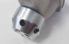


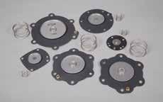

141 accessories ACCESSORIES MULTI-TRIGGER NOZZLE PLUGS COUNTER NUTS PRESSURE ADJUSTMENT FILTERS FILTER PLUG DIAPHRAGM 141
Certified Header Tank Pulse Valves
 DUST FILTER COMPONENTS Certified Header Tank Pulse Valves for Dust Collector Filters Electronic control Systems TURBO TEAM 2 0 0 8 Technical Development 1 TURBO HEADER TANKS Certified Header Tank ACCORDING
5 TANK ¾ VALVE AND 6 TANK 1 VALVE HEADER TANK SOLUTIONS PENTAIR CLEAN AIR SYSTEMS
 HEADER TANK SOLUTIONS PENTAIR CLEAN AIR SYSTEMS Standard ColourRHEADER TANK SOLUTIONS DESCRIPTION The patented Mecair Full Immersion System consists of a round header tank with fully integrated diaphragm
10 TANK WITH 2 VALVE HEADER TANK SOLUTIONS PENTAIR CLEAN AIR SYSTEMS
 HEADER TANK SOLUTIONS PENTAIR CLEAN AIR SYSTEMS Standard ColourR FULL IMMERSION SYSTEM DESCRIPTION The patented Mecair Full Immersion System consists of a round header tank with fully integrated diaphragm
THE TOTAL SOLUTION PROVIDER
 THE TOTAL SOLUTION PROVIDER R R THE TOTAL SOLUTION PROVIDER DESCRIPTION The Full immersion Patented System consists of a round header tank with fully integrated diaphragm valves, suitable for Dust collector
6 & 8 TANKS WITH 1½ VALVES HEADER TANK SOLUTIONS PENTAIR CLEAN AIR SYSTEMS
 HEADER TANK SOLUTIONS PENTAIR CLEAN AIR SYSTEMS PENTAIR CLEAN AIR SYSTEMS SOLUTIONS BY GOYEN & MECAIR Engineering partnerships since 1935 Clean Air Systems, through leading global brands Goyen and Mecair,
MECAIR 400 SERIES MANIFOLD MOUNT VALVES CLEAN AIR SOLUTIONS PRODUCT LEAFLET
 400 SERIES MANIFOLD MOUNT VALVES CLEAN AIR SOLUTIONS CONSTRUCTION FEATURES VALVE DESCRIPTION COVER BODY PILOT DIAPHRAGM BOLTS AND SCREWS DIAPHRAGM BACKING DISK DIAPHRAGM SPRING Diecast aluminium (anodised)
MECAIR 600/700 SERIES FLANGED VALVES CLEAN AIR SOLUTIONS PRODUCT LEAFLET
 600/700 SERIES CLEAN AIR SOLUTIONS CONSTRUCTION FEATURES VALVE COVER BODY PILOT DIAPHRAGM BOLTS AND SCREWS DIAPHRAGM BACKING DISK DIAPHRAGM SPRING Diecast aluminium (anodised) Diecast aluminium (anodised)
MECAIR 300 SERIES DRESSER NUT VALVES CLEAN AIR SOLUTIONS PRODUCT LEAFLET
 300 SERIES DRESSER NUT VALVES CLEAN AIR SOLUTIONS GENERAL CHARACTERISTICS CONSTRUCTION FEATURES VALVE FLUIDS PRESSURE RANGE Filtered air and oil free Standard Nitrile: 20 C/+80 C Optional Viton: 30 C/+200
MECAIR 200 SERIES THREADED VALVES CLEAN AIR SOLUTIONS PRODUCT LEAFLET
 200 SERIES CLEAN AIR SOLUTIONS - 200 SERIES CONSTRUCTION FEATURES VALVE Lock nut DESCRIPTION COVER Diecast aluminium (anodised) BODY Diecast aluminium (anodised) PILOT BASE Aluminium (anodised) PILOT Stainless
600/700 SERIES FLANGED VALVES PENTAIR CLEAN AIR SYSTEMS
 FLANGED VALVES PENTAIR CLEAN AIR SYSTEMS CONSTRUCTION FEATURES VALVE Cover Body Pilot Diaphragm Bolts and screws Diaphragm backing disk Diaphragm spring Diecast aluminium (anodised) Diecast aluminium (anodised)
mecair 5 TANK ¾ VALVE AND 6 TANK 1 VALVE HEADER TANK SOLUTIONS
 mecair 5 TANK ¾ VALVE AND 6 TANK 1 VALVE HEADER TANK SOLUTIONS Standard ColourRHEADER TANK SOLUTIONS 5 TANK ¾ VALVE AND 6 TANK 1 VALVE DESCRIPTION The patented Mecair Full Immersion System consists of
PULSE VALVES. Pulse Valves. for Dust Collector Filters
 38 PULSE VALVES Pulse Valves for Dust Collector Filters 39 TURBO PULSE VALVES R&D 40 TURBO PULSE VALVES RANGE TURBO VALVES Turbo has a complete range of pulse valves for dust collector filters able to
400 SERIES MANIFOLD MOUNT VALVES PENTAIR CLEAN AIR SYSTEMS
 MANIFOLD MOUNT VALVES PENTAIR CLEAN AIR SYSTEMS CONSTRUCTION FEATURES VALVE Cover Body Pilot Diaphragm Bolts and screws Diaphragm backing disk Diaphragm spring Diecast aluminium (anodised) Diecast aluminium
300 SERIES DRESSER NUT VALVES PENTAIR CLEAN AIR SYSTEMS
 DRESSER NUT VALVES PENTAIR CLEAN AIR SYSTEMS CONSTRUCTION FEATURES VALVE Cover Diecast aluminium (anodised) Body Diecast aluminium (anodised) Pilot base Brass (chromed) Pilot Diaphragm NBR Bolts and screws
200 SERIES THREADED VALVES PENTAIR CLEAN AIR SYSTEMS
 THREADED VALVES PENTAIR CLEAN AIR SYSTEMS Lock nut DESCRIPTION The is a range of diaphragm valves suitable for dust collector applications, in particular for reverse pulse-jet filter cleaning of filter
RAINTIGHT ENCLOSURE. mecair CSN
 mecair RAINTIGHT ENCLOSURE GENERAL CHARACTERISTICS Operating temperature Weight 20 C/+60 C 5 3.5 kg 8 5 kg 12 7 kg CONSTRUCTION FEATURES ENCLOSURE Cover Diecast aluminium (anodised) Base Extruded aluminium
Spare Parts Catalogue
 COMPANY MAN 24 CONTACT 2017 Spare Parts Catalogue HOME EUROTRADING was only founded in 1989 in Italy but with a 50 years experience matured on the fi eld in Ethiopia, Somalia, Zimbabwe, Kenya and fi nally
BALL VALVE - 10 SERIES Electric actuator - El-O-Matic
 DN B C D BALL VALVE - 10 SERIES Electric actuator - El-O-Matic E L DIMENSIONS: (mm) DN Ø L B C EL D E Kg 10 3/8" 36 33 73 55 298 95 7,8 15 1/2" 36 33 73 55 298 95 7,8 20 3/4" 39 36 76 55 301 95 8,3 25
Pulse Valves for dust collector filters
 Pulse Valves for dust collector filters DUST FILTER COMPONENTS PULSE VALVES TURBO VALVE RANGE TURBO VALVE Turbo has a complete range of pulse valves for dust collector filters able to meet all customers
12 TANKS WITH 2½ AND 3 VALVES HEADER TANK SOLUTIONS PENTAIR CLEAN AIR SYSTEMS
 HEADER TANK SOLUTIONS PENTAIR CLEAN AIR SYSTEMS DESCRIPTION The 3 CA76MR, RCA76MR and the 2.5 CA62MR and RCA62MR pulse-jet valves are designed for direct mounting to nominal 12 diameter cylindrical manifolds.
ECONOMISER SERIES E2T USER MANUAL
 TURBO S.R.L. Electronic Control Systems for Dust Collectors e-mail: info@turbocontrols.it web: www.turbocontrols.it TEL. ++39 (0)362 574024 FAX ++39 (0)362 574092 ECONOMISER SERIES E2T USER MANUAL 24/06/2014
MM & MR SERIES MANIFOLD MOUNT VALVES PENTAIR CLEAN AIR SYSTEMS
 MM & MR SERIES MANIFOLD MOUNT VALVES PENTAIR CLEAN AIR SYSTEMS GOYEN MM SERIES PULSE JET VALVES MM Series DESCRIPTION Very high performance diaphragm valve designed to be mounted directly into the compressed
POWER PULSE VALVES integral pilot (external exhaust) threaded or Quick Mount connection 3/4 to 1 1/2
 threaded or Quick Mount connection 3/4 to 1 1/2") POWER PULSE VALVES integral pilot (external exhaust) threaded or Quick Mount connection 3/4 to 1 1/2 NC 2/2 Series 353 X003GB2009/R8 EATURES The piston cartridge pulse valves are especially designed for
POWER PULSE VALVES integral pilot (external exhaust) threaded or Quick Mount connection 3/4 to 1 1/2 NC 2/2 Series 353 X003GB2009/R8 EATURES The piston cartridge pulse valves are especially designed for
MECAIR PXA/PEX HAZARDOUS PILOTS CLEAN AIR SOLUTIONS PRODUCT LEAFLET
 PXA/PEX CLEAN AIR SOLUTIONS GENERAL CHARACTERISTICS PROTECTION COIL INSULATION COIL VOLTAGE POWER CONSUMPTION ENCLOSURE ELECTRICAL CONNECTION APPROVALS INERIS II 2 Ex td A21 IP67 T135 C Class H 24 V AC
MACH 16 VALVES DISTRIBUTORS
 MACH 16 VALVES Available in size 1/8 only, versions 5/2 and 5/3 and with pneumatic and solenoid actuation. The mach 16 valve is a typical small size valve, only 16 mm wide, with excellent performance 750
GOYEN MM & MR SERIES MANIFOLD MOUNT VALVES CLEAN AIR SOLUTIONS PRODUCT LEAFLET
 MM & MR SERIES MANIFOLD MOUNT VALVES CLEAN AIR SOLUTIONS MM SERIES - PULSE JET VALVES OPERATION INSTALLATION DESCRIPTION Very high performance diaphragm valve designed to be mounted directly into the compressed
Shut-off dampers. Type AK-Ex. For low-leakage shut-off of volume flows in potentially. explosive atmospheres (ATEX) PD AK-Ex 1.
 PD AK-Ex 1.") X X testregistrierung Shut-off dampers Type ATEX-compliant parts and units For low-leakage shut-off of volume flows in potentially explosive atmospheres (ATEX) Circular shut-off dampers for shutting off
X X testregistrierung Shut-off dampers Type ATEX-compliant parts and units For low-leakage shut-off of volume flows in potentially explosive atmospheres (ATEX) Circular shut-off dampers for shutting off
GTV Series High Pressure Control Valves
 For primary and secondary shut off of fuel control lines Keeping the World Flowing Contents Section Page Technical Specification 3 ¾" & " 2-Way Poppet Valve 4 ¾" & " 3-Way Poppet Valve 5 /2", 2" & 3" 2-Way
BALL VALVE SERIES Electric actuator - El-O-matic
 BALL VALVE - 715 SERIES Electric actuator - El-O-matic E D C B A L DIMENSIONS: (mm) DN Ø A L B EL C D E Kg 15 1/2" 54,0 108 21,5 EL55 61,5 316,5 95 8,45 20 3/4" 60,0 117 26 EL55 66 321 95 8,95 25 1" 65,0
PNEUMATIC CYLINDERS CYLINDERS ISO solutions SERIES 21 SERIES 21 CYLINDERS ISO 15552
 PNEUMATIC CYLINDERS 1 2 3 4 SERIEs 21- General Information 32-100 mm diameter 21 series cylinders are manufactured to ISO 15552 standard which specifies interchangeable mounting dimensions. The cylinder
MPS AND MPS PR¼ 16 OUTPUT DEMAND CONTROLLER PENTAIR CLEAN AIR SYSTEMS. AVS Danmark ApS Skelvej Hedehusene
 MPS AND MPS PR¼ 16 OUTPUT DEMAND PENTAIR CLEAN AIR SYSTEMS MPS DESCRIPTION The Model MPS has been designed to guarantee the control of diaphragm valves mounted on pulse-jet dust collector filters containing
BALL VALVE SERIES Pneumatic actuator - El-O-Matic
 B C D E BALL VALVE - 730 SERIES Pneumatic actuator - El-O-Matic FIGURE: PD: Pneumatic actuator, double acting PE: Pneumatic actuator, spring return G F A L DIMENSIONS: (mm) Ø L A B PD PE PD C D E F Kg
Solenoid valves VZWM-L
 q/w Worldwide: Superb: Easy: Festo core product range Covers 80% of your automation tasks Always in stock Festo quality at an attractive price Reduces procurement and storing complexity qready for dispatch
Type 2511/12. Type Type 2030 Cable plug. ASI cable plug. Dosing control. General technical data Orifice Type 6518
 3/2-, 5/2- and 5/3-way Solenoid Valves for process pneumatics Type 658 standard standard High flow-rate capacity Reduced power consumption Single or manifold mounting Standard-, EEx m and EEx i versions
MULTIPLE CONNECTORS MACH 16
 Mach 16 valves can be mounted on bases with pneumatic or electrical connection. The electric contacts of the individual valves are connected by means of a printed circuit board in a sealed conduit to a
3/2-, 5/2- and 5/3-way Solenoid Valves for process pneumatics
 /2-, 5/2-5/-way Solenoid Valves for process pneumatics Type 658 stard High flow-rate capacity Reduced power consumption Single or manifold mounting stard Type 658/659 can be combined with... Stard-, EEx
Indirect servo-operated 2/2-way solenoid valves Type EV220W 10 - EV220W 50, NBR and EPDM versions
 Data sheet Indirect servo-operated 2/2-way solenoid valves Type EV220W 10 - EV220W 50, NBR and EPDM versions EV220W is a range of compact indirect servo- operated 2/2 way solenoid valves with connections
BALL VALVE - 340BA SERIES Pneumatic actuator - El-O-Matic
 C D E BALL VALVE - 30BA SERIES Pneumatic actuator - El-O-Matic FIGURE: PD: Pneumatic actuator, double acting PE: Pneumatic actuator, spring return G F DIMENSIONS: (mm) Ø DN C PD PE PD D E F Kg PE D E G
3/2-, 5/2- and 5/3-way Solenoid Valves for process pneumatics
 /-, 5/- 5/-way Solenoid Valves for process pneumatics Type 658 stard High flow-rate capacity Reduced power consumption Single or manifold mounting stard Type 658/659 can be combined with... Stard-, EEx
Solenoid valves VZWM-L, NPT
 Key features and type codes General Indirectly actuated diaphragm valve Process valve connection N14 N2 Flow rate 1400 31000 l/min Available in brass or stainless steel casting Wide range of coils VZWM
Servo-operated 2/2-way solenoid valves Type EV220A
 Data sheet Servo-operated 2/2-way solenoid valves Type is a compact servo-operated 2/2-way solenoid valve program, especially designed for use in machines and equipment with limited space. Features and
BALL VALVE SERIES Pneumatic actuator - El-O-Matic
 B C D E BALL VALVE - 1515 SERIES Pneumatic actuator - El-O-Matic FIGURE: PD: Pneumatic actuator, double acting PE: Pneumatic actuator, spring return G F A L DIMENSIONS: (mm) DN L A B PD PE PD C D E F Kg
STAINLESS STEEL ATEX 2/2 SOLENOID VALVE SPU225-X NF
 MAIN CHARACTERISTICS The SPU 225-X is a pilot operated ATEX 2/2 solenoid valve in stainless steel. It s intented for the shut-off the networks of agressive fluids no charged in hazardous explosives atmospheres,
Pressure transmitter for industrial applications Type MBS 4510
 MAKING MODERN LIVING POSSIBLE Data sheet Pressure transmitter for industrial applications Type MBS 4510 The high accuracy flush diaphragm pressure transmitter MBS 4510 is designed for use in non-uniform,
BALL VALVE SERIES Pneumatic actuator - El-O-Matic
 C D E BALL VALVE - 1370 SERIES Pneumatic actuator - El-O-Matic FIGURE: PD: Pneumatic actuator, double acting PE: Pneumatic actuator, spring return G F L DIMENSIONS: (mm) Ø L C PD PE PD D E F Kg PE D E
C-CP1. Company Profile
 C-CP1 Company Profile Calobri was founded in 1948 in Settimo Milanese (Milan), Italy and is part of the OMB group since 1998. The plant is 4,500 sqm and equipped with CNC machines and assembly and test
BUTTERFLY VALVE - 18/28 SERIES Pneumatic actuator - El-O-Matic
 B C D FIGURE: PD: Pneumatic actuator, double acting PE: Pneumatic actuator, spring return BUTTERFLY VALVE - 18/28 SERIES Pneumatic actuator - El-O-Matic G F L The pneumatic actuator is calculated for 6
motor driven metering pumps
 motor driven metering pumps DIAPHRAGM ACTUATED TYPE motor driven dosing pumps diaphragm type Welcome to FWT Dosing Systems FWT (Fluid and Water Technology) is a company formed with specialised experts
SPOOL VALVES. pilot operated single/dual solenoid (mono/bistable function) ISO mm - pad mounting body M12 connection
 ISO mm - pad mounting body M12 connection") SPOOL VALVES pilot operated single/dual solenoid (mono/bistable function) ISO 1507-18 mm - pad mounting body M1 connection x/ - 5/ - 5/ Series 50 ISO 1507- (18 mm) FEATURES M1 connection with electrical
SPOOL VALVES pilot operated single/dual solenoid (mono/bistable function) ISO 1507-18 mm - pad mounting body M1 connection x/ - 5/ - 5/ Series 50 ISO 1507- (18 mm) FEATURES M1 connection with electrical
BUTTERFLY VALVE 27 SERIES Pneumatic actuator - El-O-Matic
 C D E FIGURE: PD: pneumatic actuator, double acting PE: pneumatic actuator, spring return PEO: pneumatic actuator, spring return, normally open BUTTERFLY VALVE 27 SERIES Pneumatic actuator - El-O-Matic
BUTTERFLY VALVE - N1234 SERIES Pneumatic actuator - El-O-Matic
 B C D BUTTERFLY VALVE - N123 SERIES Pneumatic actuator - El-O-Matic FIGURE: PD: Pneumatic actuator, double acting PE: Pneumatic actuator, spring return G F L DIMENSIONS: (mm) DN L B PD PE PD C D F Kg PE
516VX1VSSBIPD Pneumatic actuator - El-O-Matic
 DN B 00 mm D E 56VXVSSBIPD Pneumatic actuator - El-O-Matic F E A L DIMENSIONS: (mm) DN L A B PD PE PD D E F Kg PE D E G Kg 5 5 53 6 25 266 286 59, 0 239 259 20 5,7 20 20 52 53 25 273 293 59, 65 258 278
BUTTERFLY VALVE SERIES Pneumatic actuator - El-O-Matic
 B C D BUTTERFLY VALVE - 223 SERIES Pneumatic actuator - El-O-Matic FIGURE: PD: Pneumatic actuator, double acting PE: Pneumatic actuator, spring return G F L DIMENSIONS: (mm) DN L B PD PE PD C D F Kg PE
BALL VALVE HIT SERIES Pneumatic actuator - El-O-Matic
 B C D E BALL VALVE - 516 HIT SERIES Pneumatic actuator - El-O-Matic FIGURE: PD: Pneumatic actuator, double acting PE: Pneumatic actuator, spring return G F A L DIMENSIONS: (mm) DN L A B PD PD C D E F Kg
BALL VALVE SERIES Pneumatic actuator - El-O-Matic
 B C D E BALL VALVE - 350 SERIES Pneumatic actuator - El-O-Matic FIGURE: PD: Pneumatic actuator, double acting PE: Pneumatic actuator, spring return G F DIMENSIONS: (mm) Ø DN B PD PE PD C D E F Kg PE C
BUTTERFLY VALVE 17 SERIES Gearbox
 DN H1 H2 H3 BUTTERFLY VALVE 17 SERIES Gearbox FIGURE: 17234ER: 17234BR: 17234VR: Seat in EPDM, with gearbox Seat in Buna, with gearbox Seat in Viton, with gearbox B ØR L DIMENSIONS: (mm) DN L B XR H1 H2
MINI-SOLENOID VALVES ISO (CNOMO, size 15) interface direct operated, pad mounting body connector size 15
 interface direct operated, pad mounting body connector size 15") MINI-SOLENOID VALVES ISO 58 (CNOMO, size 5) interface direct operated, pad mounting body connector size 5 NC / Series 0 FEATURES Compact, monobloc solenoid pilot valve with spade-plug connector type EN
MINI-SOLENOID VALVES ISO 58 (CNOMO, size 5) interface direct operated, pad mounting body connector size 5 NC / Series 0 FEATURES Compact, monobloc solenoid pilot valve with spade-plug connector type EN
Solenoid valves VZWM-L
 Key features and type codes Brief description Indirectly controlled poppet valve with diaphragm control Connection, valve G¼ G2 Flow rate 1,400 31,000 l/min Available in brass or stainless steel casting
HANDBOOK SOLENOID VALVES. Ed SOLENOID VALVES VS-ED 01/ ENG 1
 HANDBOOK Ed. 2017 1 CHAPTER 5 NORMALLY-CLOSED FOR REFRIGERATION PLANTS THAT USE HC REFRIGERANTS APPLICATION The solenoid valves illustrated in this chapter have been developed by Castel for all those refrigeration
Type AK-Ex FOR LOW-LEAKAGE SHUT-OFF OF VOLUME FLOWS IN POTENTIALLY EXPLOSIVE ATMOSPHERES (ATEX)
") Homepage > Products > Control units > Shut-off and restriction > Shut-Off Devices > Type AK-Ex Type AK-Ex FOR LOW-LEAKAGE SHUT-OFF OF VOLUME FLOWS IN POTENTIALLY EXPLOSIVE ATMOSPHERES (ATEX) Circular shut-off
Homepage > Products > Control units > Shut-off and restriction > Shut-Off Devices > Type AK-Ex Type AK-Ex FOR LOW-LEAKAGE SHUT-OFF OF VOLUME FLOWS IN POTENTIALLY EXPLOSIVE ATMOSPHERES (ATEX) Circular shut-off
Metal tube flowmeters. Series SC250. Metal Tube Flow Meters. Series SC250. Variable area flowmeter for liquids, gases and steam
 Metal tube flowmeters Variable area flowmeter for liquids, gases and steam Metallic or plastic tube with a robust construction Indication by means of magnetic coupling Scales calibrated in l/h, m 3 /h,
VALVES ISO 5599/1, SERIES IPV-ISV
 VALVES ISO 5599/, SERIES IPV-ISV The assembly surface dimensions of ISO, ISO2 and ISO 3 valves are to ISO5599-. They are available in the 5-way versions with 2 and 3 positions and with pneumatic or solenoid
Continuous level measuring system NB 4000 Selection list
 Table of contents Page Overview P2 Specification / application P3 P4 Options / Accessories P6 Dimensions / materials P7 Spare parts P9 Electrical installation P11 Subject to change. All dimensions in mm
Reverse jet pulse valves VZWE, solenoid actuated
 Key features and product range overview Function Reverse jet pulse valves VZWE are piloted 2/2-way valves. They generate pulses of compressed air using a suitable solenoid coil for mechanically cleaning
BALL VALVE SERIES Pneumatic actuator - El-O-Matic
 C D E BALL VALVE - 390 SERIES Pneumatic actuator - El-O-Matic FIGURE: PD: Pneumatic actuator, double acting PE: Pneumatic actuator, spring return G F DIMENSIONS: (mm) Ø DN C PD PE PD D E F Kg PE D E G
STAINLESS STEEL ATEX 2/2 SOLENOID VALVE SPU220-X NF
 Pressure (bar) STAINLESS STEEL ATEX 2/2 SOLENOID VALVE SPU220-X NF MAIN CHARACTERISTICS The SPU 220-X is a direct acting ATEX 2/2 solenoid valve in stainless steel. It s intended for the shut-off the networks
Tie rods cylinders to ISO standard Ø
 Tie rods cylinders to ISO 5552 standard 25 DESCRIPTION Cylinders series "XL" comply with ISO 5552 standard, being in this way completely interchangeable with the former cylinders to ISO 643 /VDMA 24562
Electromagnetic flowmeters Series FLOMAT Insertion electromagnetic flowmeter for conductive liquids
 Electromagnetic flowmeters Series FLOMAT Insertion electromagnetic flowmeter for conductive liquids For use in large diameter pipes as an economical solution for flow measurement Flow rate measurement
flowserve.com Flowserve Solenoid Valves Namur, Remote and Banjo Mounted Designs for Precision Control
 flowserve.com Flowserve Solenoid Valves Namur, Remote and Banjo Mounted Designs for Precision Control Flowserve Solutions to Keep You Flowing Flowserve is one of the world s leading providers of fluid
15 mm Pilot Valve. More technical specifications are reported in the following pages. 1
 15 mm Pilot Valve The 15 mm pilot valve has been designed and developped by Amisco as a logical evolution of the traditional product range manufactured for the pneumatic market. The 15 mm solenoid valve
ISE/N Automatic valve
 ISE/N Automatic valve for petroleum products www.isoilmeter.com The solutions that count LEAFLET: PR/VA/000 Edition February 201 ISE/N Automatic valve for petroleum products One of the main features of
GIG/GIGS/GPO Gas Powered Actuators. GIG/GIGS/GPO gas powered actuators
 GIG/GIGS/GPO Gas Powered Actuators GIG/GIGS/GPO gas powered actuators A world Of experience Biffi has been a leading manufacturer of valve actuators for more than 50 years. As one of the few manufacturers
m-csg Ultra-compact Clean Steam Generation System
 Local regulations may restrict the use of this product to below the conditions quoted. In the interests of development and improvement of the product, we reserve the right to change the specification without
VALVE WITH SA ELECTRIC ACTUATOR
 752-753 VALVE WITH SA ELECTRIC ACTUATOR CHARACTERISTICS The 752-753+SA ball valve is dedicated to the automatic opening/shut-off of pipes carrying unloaded industrial fluids with a 16 bar maximum pressure.
Regenerative Turbine Pumps
 Bulletin E4 July E4/T4 Series Regenerative Turbine Pumps Capacities to GPM Heads to 6 Feet Temperatures to F MTH E4/T4 Series Close-coupled and pedestal mounted regenerative turbine pumps represent the
High Flow Valve Actuation Range. NAMUR Valves G1/4" & G1/2" Piped Valves G1/4" & G1/2" Banjo Valves G1/8" & G1/4"
 31-37 High flow NAMUR valves G1/ and G1/ aerospace climate control electromechanical filtration fluid & gas handling hydraulics pneumatics process control sealing & shielding High Flow Valve Actuation
4 qwer. Main Pulse Valves Dust Collector 2/2 SERIES H OME PAGE P RINT. High Flow. Aluminum Bodies Air and Inert Gas 3/4" to 3" NPT.
 4 qwer High Flow Main Pulse Valves Aluminum Bodies Air and Inert Gas 3/4" to 3" NPT NC 2/2 SERIES Features Specially designed for reverse jet-type dust collector systems. High flow Cv s to 140 for effective
motor driven metering pumps
 motor driven metering pumps DIAPHRAGM ACTUATED TYPE motor driven dosing pumps diaphragm type Welcome to FWT Dosing Systems FWT (Fluid and Water Technology) is a company formed with specialised experts
BC-VDC A TOTAL SYSTEM FOR YOUR DUST COLLECTOR DWYER INSTRUMENTS, INC. DWYER OFFERS YOU:
 BC-VDC SPRINGLESS DIAPHRAGM PULSE VALVES DCS/RDCS SPRINGLESS DIAPHRAGM PULSE VALVES Ease of Installation: Industry standard right angle body with 90 angle between inlet and outlet. Most sizes offer the
SPOOL VALVES solenoid air operated 1/4 to 1/2 tapped body and NAMUR for integrated pilot
 SPOOL VALVES operated / to / tapped body and NAMUR for integrated pilot ATEX /-/ Series - FEATURES The valves offer environmental protection against the ingress of liquids, dusts or other foreign matter
Electronic Monitoring Systems
 JJ Electronic digital thermometer JJ Multi-channel temperature indicator JJ Temperature sensors JJ KombiTemp Electronic Monitoring Systems and Temperature Sensors DS_Electronic_monitoring_systems_and_temperature_sensors
Solenoid valve Types EV220B 15 - EV220B 50
 Data sheet Solenoid valve Types EV220B 15 - EV220B 50 EV220B 15 EV220B 50 is a universal indirect servo-opera ted 2/2-way solenoid valve program. Valve body in brass, dezincification resistant brass and
BUTTERFLY VALVES + NA ELECTRIC ACTUATOR
 1150-1158 BUTTERFLY VALVES + NA ELECTRIC ACTUATOR CHARACTERISTICS The butterfly valves 1150 to 1158 are dedicated to the automatic opening/shut-off of various fluid pipes. It has a ductile iron body. Thanks
-V- New. Valve series VOFC. 2009/08 Subject to change Internet:
 Valve series VOFC 2009/08 Subject to change Internet: www.festo.com/catalogue/... 159 Solenoid valves VOFC Key features General information The valves in the VOFC series are special 3/2-way and 5/2-way
SLK SERIES SAFETY VALVES
 SLK SERIES SAFETY VALVES SLK SERIES TABLE OF CONTENTS Relief Valves SLK-Series are spring loaded pressure relieving devices, suitable for discharge of compressible fluids. SLK-series safety valves are
Control Stations & Switches: Control Stations Increased Safety Unicode 2 Series: Pre-drilled Control Stations
 Unicode 2 Series: Pre-drilled Control Stations Polamide U43W211 Polyester U23W211 Compliance Data: ATEX IEC and IECEx (Polyester): Stainless Steel U62W229 Aluminum U83W211 ATEX IEC / IECEx CE Ex de IIC
Flow. group *2) G1/4 1, , B G1/ , B /4 NPT , B N/en
 G1/4 1, , B G1/ , B /4 NPT , B N/en") / poppet valves electromagnetic actuated, directly controlled G /4, G / or /4 NPT Working from 0 bar up Short switching times Suited for fine vacuum down to,33 0 - mbar For a.c. solenoid systems with integrated
/ poppet valves electromagnetic actuated, directly controlled G /4, G / or /4 NPT Working from 0 bar up Short switching times Suited for fine vacuum down to,33 0 - mbar For a.c. solenoid systems with integrated
FF03. Rotary Blade Level Switch for bulk goods. Level Measurement and Monitoring
 Level Measurement and Monitoring FF03 Rotary Blade Level Switch for bulk goods For bulk good with grain size up to 150 mm and bulk weight from 0,01 up to more than 2,0 t/ m³ Robust aluminium diecast housing
Safety Relief Valves Commanche Techmatic Controls
 Safety Relief Valves Commanche Techmatic Controls Product description Material Properties Connection W. Pres (Bar) W. Temp ( ) 1. Commanche-317 ISO 9001 (DN 12-50) SV-B27 Bronze Without lever Threaded
Knife gate valve SLF. Data is only for informational purpose. All specifications are subject to change without notice issue 3
 Knife gate valve SLF Data is only for informational purpose. All specifications are subject to change without notice. V R 1 2013-02-15 issue 3 Knife gate valve SLF Stafsjö s knife gate valve SLF is a flanged
Proportional pressure reducing valves type DHRZO and DHRZA standard and ex-proof version, direct operated, ISO 4401 size 06
 www.atos.com Table TF040-2/E Proportional pressure reducing valves type DHRZO and DHRZA standard and ex-proof version, direct operated, ISO 4401 size 06 A B DHRZO-A-012/25 A B DHRZA-A-010/25 DHRZ* are
Ignition devices. Lighting up Innovation
 Ignition devices Lighting up Innovation Proven leader in the industrial ignition industry, Tesi manufactures a unique range of high energy, high voltage and portable ignition systems assuring ignition
NON-SLAM PISTON CHECK VALVE GUARDIAN SERIES
 NON-SLAM PISTON CHECK VALVE GUARDIAN SERIES BEHIND THE NAME With a renewed focus on product leadership through innovation and quality, C&C is your world class provider of flow solutions. Pulsating and
motor driven metering pumps
 motor driven metering pumps DIAPHRAGM ACTUATED TYPE www.fwtsystems.it motor driven dosing pumps diaphragm type Welcome to FWT Dosing Systems FWT (Fluid and Water Technology) is a company formed with specialised
SOLENOID VALVES FOR REFRIGERATING SYSTEMS
 SOLENOID VALVES 17 SOLENOID VALVES FOR REFRIGERATING SYSTEMS APPLICATIONS The solenoid valves, shown in this chapter, are classified Pressure accessories in the sense of the Pressure Equipment Directive
BOX A3 TEST R. Bocconi. REL. DATE R.T. Check and Approval
 BOX A3 TEST 7 20-02-2018 R. Bocconi REL. DATE R.T. Check and Approval INDEX 1 - FOREWORD...... Page 3 2 - BOX A3 TEST FOR HYDRAULIC LIFTS... Page 3 2.1 GENERAL OPERATION... Page 3 2.2 HOW THE CHECK OF
Knife gate valve HG - Standard
 Knife gate valve HG - Standard V R Data is only for informational purpose. All specifications are subject to change without notice. 1 Knife gate valve HG Stafsjö s knife gate valve HG has excellent flow
BUTTERFLY VALVE - N1234 SERIES Pneumatic actuator - Actreg
 B C D BUTTERFLY VALVE - N1234 SERIES Pneumatic actuator - Actreg FIGURE: AD: Pneumatic actuator, double acting AS: Pneumatic actuator, spring return G F L DIMENSIONS: (mm) DN L B AD AS AD C D F Kg AS C
Features BALL VALVES. Split Wafer. Carbon steel wafer PN ANSI 600 STANDARD FEATURES FEATURES ON REQUEST
 OMAL S.p.a. Via Ponte Nuovo, 11-25050 Rodengo Saiano (BS) ITALY Phone +39 0308900145 - Fax +39 0308900423 Booked in the Enterprise Register of: Brescia number 1661640175 Share capital completely deposited:
3/2-5/2 ports / positions
 Series SOLENOID SPOOL VALVES G / THREADED PORTS with CNOMO pilots /-/ ports / positions SPECIFICATIONS FLUID : or neutral gas, filtered, lubricated or not PORTS : G/ PRESSURE : to 0 bar TEMPERATURE RANGE