Russian Motorcycle Evolution
|
|
|
- Georgia Marshall
- 5 years ago
- Views:
Transcription

 Ernie Franke eafranke@tampabay.rr.")
1 Ural (Урал) - Dnepr (Днепр) Russian Motorcycle Evolution Part IV: Ignition Systems (See Also Part I: Parade of Russian Sidecar Motorcycles, Part II: Engine Evolution, Part III: Alternator and Generator Evolution, and Part V: Carburetor Evolution) Ernie Franke eafranke@tampabay.rr.com 11 / 2017
2 Ignition Systems for Russian Motorcycles (Plotting the Migratory Course) We have seen different distributor/breakers ranging from the PM-05, manually controlled from a spark-advance lever on the left handlebar, to the automatic breaker PM-302, providing automatic change of ignition timing depending on engine speed. Modern, contact-less, electronic ignition migrated through Types I to Type V before arriving at the robust Ducati and Power Arc ignition systems. We have also seen a migration in ignition coils, starting with the KM-01 in the original M-72, and terminating with the distributor-less, compact units used in the electronic ignition systems. Enclosed is a briefing where we tried to pull together a lot of information to make sense of this migration path. Interestingly enough, one can almost identify the model and year of the Ural or Dnepr by the original electrical components. One notices that components (regulator, distributors/breakers, ignition coils and 6/12-Volt batteries) are usually paired together. Often one component may migrate faster than another component in the ignition system. This brought about a few mid-model changes. I hope this information helps sort-out the ignition systems of heavy Russian motorcycles and I look forward to receiving helpful suggestions for further clarification and sources of more information. 2
3 Outline of Ignition Study See Separate Study on Russian Motorcycle Ignition Systems Association and Evolution of Ignition Components (Part I) Manual Spark Advance (Part II): PM-05 Automatic Spark Advance (Part III): PM-302 Contact-Less (Electronic) Breaker Points (Part IV): Type I -to- Type V, Ducati, Power Arc and Powerdynamo Ignition Systems Ignition (Induction) Coils (Part V) Setting Timing on Manual, Automatic and Electronic Ignition Systems (Part VI) Handlebar Control Switch (Part VI) This study traces the evolution of the ignition system in the Russian motorcycle. We see automation (automatic spark advance/retard), low maintenance 3 (contact-less breaker points) and optimization (ignition coil).
4 Russian Ignition Systems Breaker/Distributors Contact Systems PM-05: Manual Spark Advance /Retard PM-11/PM-302 Breakers: Automatic Spark Advance Contact-Less (Electronic) Systems Type I -to- Type V Ignition Systems Ducati Ignition System Power Arc Ignition System Ignition Coils Associated with Breaker / Distributor Systems KM-01 Coil PM-05 Breaker / Distributor IG-4048 Coil PM-05 Breaker / Distributor B11 Coil PM-05 Breaker / Distributor B2B (B2Б) Coil PM-05 Breaker / Distributor B201 Coil PM-11 or PM-302 Breaker B204 Coil PM-302/302A Breaker Setting the Timing Static Timing Dynamic (Timing Light) Timing Within each ignition system, each breaker/distributor is associated (paired) 4 with a distinctive, corresponding ignition coil.
5 Table I: IMZ (ИМЗ) - Ural (Урал) Model/Year vs. Electrical System Model Year Engine Size Voltage M cc 6-Volt M-72M cc 6-Volt Generator/ Alternator G-11, G-11A (1952) Regulator PP-1, PP-31 (1950) Ignition Coil KM-01, B2B, IG-4085B (1950) Breaker/ Distributor PM-05 G-11A (1952) PP-31A KM-01 PM-05 Battery 3MT-7 (7A-hr) or 3MT-14 (14A-hr) M-72K cc 6-Volt *Magneto* None - PM-05 None M cc 6-Volt G-11A (1952) M cc 6-Volt G-414 (1957) M-63 (Ural-2) cc 6-Volt G-414 (1957) M-66 (Ural-3) cc 6-Volt G-414 (1957) M cc 12-Volt G-424 (1974) M cc 12-Volt G-424 (1974) and Series ,8.103X, 8.123,8.123X 650 & 750 Series 8.103,8.103X, 8.123,8.123X 750 Series PP-30, PP-31A (1956) B11, KM-01 PM-05 PP-31 B2B (1963) PM-05 PP-302, PP-302A B201, B201A PM-302, PM-302A PP-302 (1963), PP-302A PP-302 (1963), PP-302A cc 12-Volt G-424 (1974) PP-330, (1992) present 750cc 12-Volt (1998) 750cc 12-Volt Nippon Denso (2004) B2B (1963) PM-11A B201, B201A PM-302, PM-302A B201, B201A PM-302, PM-302A PP-302A, PP-330 B204 PM-302, PM-302A PP-330, (1992) B204 PM-302, PM-302A Internal to Alternator (YA212A11E) Internal to Alternator 3MT-12 (12A-hrs) 3MT-6 (6A-hrs) or 3MT-12 (12A-hrs) 6MTS-9 (9A-hrs) or 2X 3MT-6 (2X 6A-hrs) B204 PM-302A (1982) 6MTS-9 or 6CT-18-36A BC3 (BZ3) Contact-less Ignition System (18-to-36A-hrs) Type I (1994), II (1997), III (1998) Contact-less Ignition System Type IV (2002) Type V (2004) Ducati (2006), Power Arc Varta YB18L 6MTS-18, Interstate FAYTX-20HL Notes: 1. M-64 (1961) and M-65 (1965) were prototypes. 2. Alternators progress in output voltage and power from Г-11 (G-11) generator of 6-Volts/45-Watts in 1941, Г-11A of 6 V/45 W in 1952, Г-414 6V/65 W in 1957, Г-424 of 12V/150W in 1974, of 12V/350W in , to the present-day Nippon-Denso alternator of 12V/770W. 3. M-73 (1976) was an M-72 (750cc) with engageable sidecar wheel. 4. M-75 (1943) was experimental model with 500cc engine (6-Volt) on M-72 frame. M-76 (1947) was experimental (820cc). 5. Г-424 alternator (150 Watts) has external relay/regulator (PP-302 or PP-330) and Nippon Denso alternators have internal regulators Volt ignition coil B2B (manual spark advance) paired with PM-05 distributor, B201/B201A (ignition coil for automatic spark advance) paired with PM-302/PM-302A. B2B and B201 coils for 6-Volts and B204 for 12-Volts. 7. PP-1, PP-30, PP-31 reverse-relay/voltage regulator for generator G-11/-11A systems were replaced with PP-302/-302A voltage regulator 5for G-414, and finally P-330 for the G-424 alternator Solid-State Voltage Regulator replaced the PP-330 in 1992.
6 Table II: KMZ (KMЗ) - Dnepr (Днепр) Model/Year vs. Electrical System Model Year Engine Size Voltage Generator/ Alternator Regulator Ignition Coil Breaker/ Distributor M cc 6-Volt G-11A (1952) PP-31 (1950) KM-01, B-2B PM-05 3MT-7 (7A-hr) or M-72N (H) cc 6-Volt G-11A (1952) PP-31A (1956) KM-01 PM-05 3MT-14 (14A-hr) K-750 Battery G-11A (1952) PP-31A (1956) IG-4085 PM-05, PM-11A 3MT-7, -10, cc 6-Volt G-414 (1957) PP-302 (1963) B2B (1963), B201 PM-302 3MT-12 or -14 K-750M cc 6-Volt G-414 (1957) PP-302 (1963) MT-12 (Dnepr-12) WD WD 750cc 6-Volt G-414 (1957) PP-302 (1963), PP-302A MB cc 6-Volt G-414 (1957) PP-302 (1963) MB-750M cc 6-Volt G-414 (1957) PP-302 (1963), (1992) K-650/MT cc 6-Volt G-414 (1957) PP-302 (1963), PP-302A K-650/MT cc 6-Volt G-414 (1957) PP-302 (1963), PP-302A B2B (1963) B201 B2B (1963) B201 B2B (1963) B201 B2B (1963) B201 B2B B201 B2B B201A PM-05 PM-302 PM-05 PM-302 PM-05 PM-301/PM-302 PM-05 PM-302 PM-05, PM-11A PM-302 PM-05 PM-302 MB cc 12-Volt G-424 (1974) PP-330 B204 PM-302, PM-302A(1982) MB-650M late 90s 650cc 12-Volt G-424 (1974) PP-330 B204 PM-302A MT cc 12-Volt G-424 (1974) PP-330 B204 PM-302, PM-302A (1982) MT cc 12-Volt G-424 (1974) PP-330 B204 PM-302A (1982) MT-11 (Dnepr-11) MT-16 (Dnepr-16) cc 12-Volt G-424 (1974) PP-330, (1992) cc 12-Volt G-424 (1974) PP-30, PP-31, PP- 330, (1992) B204 PM-302A (1982) B201, B204 PM-302, PM-302A (1982) 3MT-6 3MT-12 3MT-12 3MT-12 3MT-6 or 3MT-12 6MTS-9 or 2X 3MT-6 6MTS-9 (9A-hr) Notes: 1. MT-14 (1977) was a prototype. 2. MB-650 is military version of MT-16 and MB-750 is a military version of the MT Alternators progress in output voltage and power from Г-11 (G-11) generator of 6-Volts/45-Watts in 1941, Г-11A of 6 V/45 W in 1952, Г-414 6V/65 W in 1957, Г-424 of 12V/150W in 1974, of 12V/350W in , to the present-day Nippon-Denso alternator of 12V/770W. 4. MT-11 and MT-16 remained in production until 1991 when they were re-named the Dnipro-11 (Dnepr-11) and Dnipro-16 (Dnepr-16). 5. Model # s: H = N, MW = MB = MV Solid-State Voltage Regulator replaced the PP-330 in Г-424 alternator (150 Watts) has external relay/regulator (PP-302 or PP-330) (350 Watts) alternator has internal regulator Volt ignition coil B2B (manual spark advance) paired with PM-05 distributor, B201/B201A (ignition coil for automatic spark advance) paired with PM-302/PM-302A. B2B and B201 coils for 6-Volts and B204 for 12-Volts. 6


 KIM-01 Г-11/11A:")


 IG-4085B")
 (with")


7 Motorcycle 6-Volt Electrical Systems Generator Regulator Ignition Coil Breaker/Distributor Ural: M-72, M-72M, M-61 Dnepr: M-72, M-72N PP-1 (1941) KIM-01 Г-11/11A: 45 W (1941/1952) Ural: M-62, M-63, M-66 Dnepr: K-750, K-750M, MB-750, MB-750M, K-650, MT-9, MT-12 PP-30 PP-31/PP-31A (1950/1956) IG-4085B (1950) and B11 B2B (B2Б) PM-05 (1954) (with manual spark advance) PM-11A or PM-301/PM-302/PM-302A (with automatic spark advance) Г-414: 65 W (1957) PP-302/302A (1963/197X) B201/B201A 7


")


 B204A")


 Internal")
8 Motorcycle Ural: M-67, M-67.36, IMZ Series Dnepr: MB-650, MT-10, MT-10.36, MT-11, MT-16 Г-424: 150 W (1974) 12-Volt Electrical Systems Alternator Regulator Breaker - Ignition Coil (Relay-Regulator) PP-330 (1941) B204A Contact-less Type I PM-302/PM-302A Type III Ural: IMZ Series ( ) Dnepr: None (1992) Type II Type IV : 500 W (1999) Ural: IMZ Series (2004-present) Dnepr: None Internal to Alternator (JYA212A11E) Internal to Alternator Ducati (2006) Type V Raceway Services Power Arc Nippon Denso: 770 W (2004) 8
 The primary winding has larger wire, fewer turns and higher current, compared to the multi-turn, finer wire, lower current of the high-voltage secondary winding.")
9 Basic Ignition System 1. Battery 2. Ignition Switch 3. Ignition Coil 4. Primary Winding 5. Secondary (high-voltage) Winding 6. Spark Plug 7. Rotating Cam 8. Contact Breaker Points 9. Capacitor (condenser) The primary winding has larger wire, fewer turns and higher current, compared to the multi-turn, finer wire, lower current of the high-voltage secondary winding. The basic ignition system is simple. The breaker points are normally closed, allowing the magnetic field to build in the ignition coil. When the cam shaft rises, opening the breaker points, the collapsing magnetic field induces a high-voltage 9 in the secondary winding of the coil.
 8. Signal Horn 9. Generator (Г-11) 10. Battery 11.")
10 Basic Ural M-72 Ignition System 1. Headlight Cavity 2. Hi/Lo-Beam Switch 3. Central Switch 4. Ignition Switch 5. Charge Light 6. Safety Fuse Cable from Spark-Advance Lever to PM-05 Breaker/Distributor Left Handlebar Spark Advance Lever 7. Sidecar Running Lamps (no turn signals) 8. Signal Horn 9. Generator (Г-11) 10. Battery 11. Relay Regulator (RR-1/PP-1) 12. Rear Bike Lamp 13. Ignition Coil 14. Breaker Points 15. Distributor 16. Spark (Candle) Plug 17. Horn Button Switch 18. Spark-Advance Lever 19. Hi/Lo-Beam Dimmer Lever Note: The early M-72 s had positive-ground. The same elements are shown in this drawing for the M-72, the first heavy Russian motorcycle. The spark advance lever is shown connected (dotted line) to the breaker/distributor. 10
 11. Battery 12.")
11 Ignition System of Early Urals and Dneprs 1. Spark Plug (Candle) 2. Center Contact of Distributor Rotor 3. Ignition Coil (KM-01 or IG-4085B) 4. High-Voltage Secondary Winding 5. Low-Voltage Primary Winding 6. Manual Control of Spark Advance/Retard 7. Contact Breaker Arm 8. Rotary Cam 9. Ground Contact with Locking Screw 10. Condenser (Capacitor) 11. Battery 12. Distributor (PM-05) 13. Ignition Switch Capacitor Helps to keep Points from Pitting 6-Volts 6-Volts Spark Gap: mm Breaker Gap: mm Ground 6-Volts 6-Volts Nigh-Voltage Interrupted 6-Volt Path to Ground The basic ignition system is simple. The breaker points are normally closed, allowing the magnetic field to build in the ignition coil. When the cam shaft rises, opening the breaker points, the collapsing magnetic field induces a high-voltage in the secondary winding of the coil. 11

12 PM-05 Breaker (Contact) / Distributor 1. Circuit Breaker/Distributor 2. Attachment Spring The PM-05 breaker/distributor was introduced to heavy Russian bikes on Ural s M-72. The distributor cap was fastened by a special spring. 12 High-voltage travels from the middle contact to the spark plugs (candles).

 for")
")


13 Ignition Distributor PM-05 (6-Volt) for K-750, M-72 (Part# 72172) Contact Breaker Points Distributor Cap Gasket Distributor Cap Rotor Contact Breaker Points 13

 14 to early (28-32 ) before TDC.")
14 PM-05 Breaker / Distributor for K-750 and M-72 Distributor Cap Distributor Rotor Contact Breaker Points The vast majority of SV 750 cm 3 engines have the manual spark-advance PM-05, where the angle is varied from late (0-4 ) 14 to early (28-32 ) before TDC.
 Input")
 Connected to Ground Output to Left Spark Plug")


15 Breaker/Distributor PM-05 Breakdown Movable Terminal (Hammer) Connected to Ignition Coil Breaker Contacts (Points) Input High-Voltage from Ignition Coil Output to Right Spark Plug Fixed Terminal (Anvil) Connected to Ground Output to Left Spark Plug Distributor Capacitor Distributor Cap High-Voltage Path thru Center Contact, then Rotor, and Out thru Side Contacts Gasket Felt Feather (oil pad) Distributor Rotor PM05 Breaker/Distributor was used on early versions of 15 Dnepr s K-650, K-750, MT-12, MB-750 and M-72.
 and")


16 PM-05 Distributor Cover (Cap) and Rotor oldtimergarage.eu ural-hamburg.de ( (oldtimergarage.eu) 16


17 Manual Spark Advance M-61, K-750 and M-72 Left Handlebar 1. Capacitor 2. Movable Contact 3. Breaker Gap 4. Fixed Contact to Ground 5. Ground Contact 6. Locking Screw 7. Gap Adjustment Screw 8. Rotating Plate 9. Cam Shaft 10. Cam Roller 11. Spring 12. Anvil 13. Advance Control Cable 14. Advance Lever Control 15. Output to Spark Plugs 16. Input from Ignition Coil 17. Central Contact 18. Contact Plate 19. Carbon Contacts to Spark Plugs The PM-05 breaker/ distributor, with manual ignition advance, consists of a body with a cap, breaker points riding on a cam, and two screws to allow rotation around an angle, which can beset for timing. The movable contact 17 can be moved to regulate the gap, with the help of the eccentric adjusting screw.
 19. Capacitor Wire 20.")

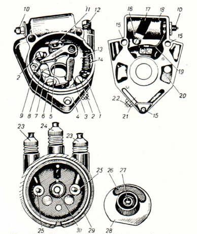
18 PM-05 Manual Advance/Retard Distributor Rotary Disk Distributor Cap Rotor Capacitor 1. Stop 2. Screw 3. Oil Felt Pad 4. Body 5. Lever 6. Screw 7. Locking Screw 8. Interrupter Plate Contact 9. Eccentric 10. Insulated Terminal 11. Contact Bracket 12. Adjusting Stop 13. Rotary Disk 14. Spring 15. Screw Hole 16. Screw 17. Plate 18. Capacitor (Condenser) 19. Capacitor Wire 20. Cut-out in Body 21. Adjusting Screw Lock-Nut 22. Adjusting Screw 23./24. Wire Conduits 25. Carbon Contact 26. Contact Plate 27. Cap with Spring 28. Rotor 29. Cover with Contacts 30. Central Contact The PM05 is controlled by the ignition lever on the left handlebar, while the later PM-302 centrifugal regulator, provided an automatic change of ignition timing depending on engine speed. 18

19 PM-05 Interrupter-Distributor 19
 2. Breaker Gap (0.4-0.6mm) 3.")
20 PM-11 and PM-302A Breaker Systems The PM-302 ignition system is not dependent on the supply voltage (6-V or 12-V). They differ only in ignition coils B-201 (6- Volt) and B-204 (12-Volt). The higher current in a 6-volt ignition system leads to increased contact breaker pitting, compared with a 12-Volt system. 1. Spark Plug ( mm gap) 2. Breaker Gap ( mm) 3. Breaker Contacts Volt Battery 5. Ignition Switch 6. Ignition Coil (B-201 or B-204) Breaker Gap mm ( ) PM-302A Breaker The basic ignition system is simple. The breaker points are normally closed, allowing the magnetic field to build in the ignition coil. When the cam shaft rises, opening the breaker points, the collapsing magnetic field induces a high-voltage 20 in the secondary winding of the coil.

 Breaker Unit Low-Voltage Primary Terminal Safety Arc Gaps The introduction of the PM-301/PM-302 breaker system eliminated any need for")
21 Breaker PM-302 and Ignition Coil B204 Dnepr MT / MT-11 / MT-16 and Ural M-62 / M-63 / M-66 / M-67 High-Tension Output to Spark Plug Mounting Ear Front Ignition Cover High-Voltage Output to Left-Side Spark Plug 1. B204 Ignition Coil 2. PM-302A (ПM-302A) Breaker Unit Low-Voltage Primary Terminal Safety Arc Gaps The introduction of the PM-301/PM-302 breaker system eliminated any need for a distributor and provided automatic spark advance/retard. The centrifugal breaker points automatically adjusted to engine rpm s. The 21 output of the ignition coil was connected directly to each of the spark plugs.
 Used with Ignition coil B201A 6-Volt) or B204 (12-Volt) Breaker Points Weight Pins Cover Carrier")

22 PM-302A (ПМ302A) 12-Volt Breaker for Dnepr (MT-10.36/ MT-11/ MT-12/ MT-16) and Ural (M-62/ M-63/ M-66/ M-67/ M-67.36/ Tourist) Used with Ignition coil B201A 6-Volt) or B204 (12-Volt) Breaker Points Weight Pins Cover Carrier Centrifugal Advance The PM-302 ushered in the era of automatic spark advance with the introduction of the centrifugal advance/retard, consisting of breaker points, condenser, advance weights and springs, 22 and earned the nick-name the mixing bowl of doom."
 and turn eccentric screw (6) in either direction. Set breaker gap to 0.4-0.6mm (0.016-0.024 ). Tighten stop screw.")

 and the")
23 PM-302A Breaker with Automatic Spark Advance To Adjust Gap: Undo screw fastening the automatic park timer. Slacken stop screw (1) and turn eccentric screw (6) in either direction. Set breaker gap to mm ( ). Tighten stop screw. Recheck gap. 1. Spring 2. Carrier 3. Weight Pin 1. Stop Screw 10. Spring 2. Contact Leg 11. Carrier 3. Breaker Body 12. Locking Ring 4. Breaker s Lever 13. Cam 5. Lever Pin 14. Weight 6. Eccentric 15. Lubrication Wick 7. Automatic Spark Timer 16. Capacitor Holder 8. Weight Pin 17. Condenser (Capacitor) 9. Bushing 18. Terminal Bushing Tension Spring Weight Pin Spark-advance is determined by the relationship between rotary speed (centrifugal force) and the tension spring. The correct placement of the two-piece advance unit s top plate is a rectangular opening at each side of the mounting bolt. 23
 3. Breaker Contacts 4. Housing 5.")


24 PM Volt Breaker Centrifugal Advance 12-Volt Breaker Points 1. Housing 2. Condenser (Capacitor) 3. Breaker Contacts 4. Housing 5. Rotary Contact 6. Bushing 7. Rotor Automatic ignition advance PM-302 Breaker consists of a body with a lid, cam with a centrifugal regulator, breaker contacts, capacitor and a felt pad to lubricate the cam. The breaker is attached to the crankcase with three screws and can be rotated at an angle, through which you can set the desired time of ignition timing. The breaker gap is set using 24 the eccentric adjusting screw.
 PM-302A 1 Screw, 2 Contact Leg, 3- Breaker Body, 4 Breaker lever, 5 Lever Pin, 6 Eccentric, 7 Automatic Spark Timer, 8")


25 PM-11 and PM-302A Breakers PM-11 1 Contact Support Fastening Screw, 2 Contact Support, 3- Fixed Contact, 4 Moving Contact, 5 Timer Weight, 6 Weight Pin, 7 Fixed Plate, 8 Fastening Screw, 9 Spring, 10 Cam, 11 Adjusting Screw, 12 Distributor Body, 13 Felt, 14 Capacitor (Condenser) PM-302A 1 Screw, 2 Contact Leg, 3- Breaker Body, 4 Breaker lever, 5 Lever Pin, 6 Eccentric, 7 Automatic Spark Timer, 8 Weight Pin, 9 Bushing, 10 Spring, 11 Carrier, 12 Locking Ring, 13 Cam, 14 Weight, 15 Felt, 16 Capacitor Holder, 17 Capacitor (Condenser), 18 - Terminal There are two styles of cam and flyweights. The one piece unit, less desirable due to soft pins that tend to wear out. The two piece unit better quality, but tricky as the top plate has to be put on correctly. When done correctly there are two square opens created, if done wrong the opens created are angular and the flyweights will not fling out and advance the timing. The PM-11 was the predecessor to the more-popular PM-302/PM-302A. The weights and springs are attached to the points cam. As the cam spins on its shaft, centrifugal force causes weights to move and turn the cam on its shaft, advancing the timing of the spark, thus giving the combustion process more time to occur as the rpm 25 increase. Full advance is usually reached around 3,000 rpm.
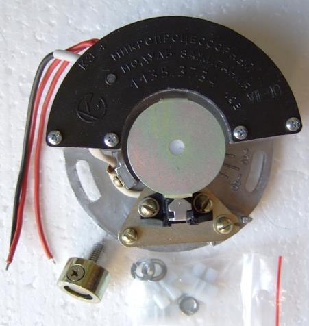
26 Types of Electronic Ignition (Vance Blosser, Russian Iron Motorcycle Club) Type I - Models from 1994 up to about '96 or '97 had a 'Type I' - a pot metal rotor on the camshaft with 2 steel slugs and a small sensor coil mounted close to the rotor. A hand-wound coil was also mounted under the front cover. The 'brains' of the box were a bit bigger than a VHS cassette and had big heat fins, mounted under the seat. The main problems with this system was a relatively weak spark, and sometimes the timing curve diodes would fail, but could be replaced with after-market ones and usually gave good service after that. Type II - Somewhere about 1997 or '98 Type II appeared. All the electronics fit inside a small C-shaped module that mounted under the front engine cover, across from the magnetic rotor sensor. A different ignition coil was fitted with a higher output. The components in the module were 'potted' (encased in epoxy) to protect against vibration, like military boards, but had issues with heat buildup. Type III - A few months after the Type II appeared, it was replaced with the Type III (approximately mid- 1998). Physically it looked the same, but the circuit board was modified to prevent heat failure. Partway into the production span of the Type III, a high-output coil was mounted outside the front engine cover so it could stay cool. This system was very reliable, although the heavy mass of the rotor sometimes caused wear of the key. A few cases of the steel slugs coming loose from the pot metal rotor were noted. Type IV - In 2002, with the adoption of 750 engines, Type IV was introduced, featuring modern electronics. The massive pot metal rotor was replaced by a lighter stamped steel unit with notches that used a Hall-effect sensor mounted in the module cover. The electronics were incorporated inside the front rotor cover. The coil was a newer design high-output unit that mounted under the front engine cover. A plastic engine cover was used for heat dissipation. A built-in diagnostic LED simplified setting timing and gave indication of unit functionality. This unit also had some heat related issues, partly caused by a method of testing during assembly on one line - a surge was damaging a component on this line during testing. Type V - In 2004 Type V appeared, which is basically a Type IV split into 2 parts. The electronics were moved out into the air-stream for cooling. The LED was visible without any disassembly. Testing in Europe revealed no problems, but there were a few issues in the US under very hot conditions. In the mid 80 s, IMZ introduced a contact-less ignition system (BSZ), produced by the Tyumen factory "Papa. It will not work or fit early 6-Volt Motorcycles which originally had manual advance and retard levers. 26

27 Type I Ignition System ( ) Ignition Module: Plastic Box with Aluminum Cooling Fins on Top Ignition Module Mounted under Seat Installed in Urals from 1994 to 1997 Pot-Metal Rotor on Camshaft with 2 Steel Slugs Sensor Coil Mounted Close to Rotor Hand-Wound Coil Mounted under Front Ignition Cover Spark Plug: HGK BP7HS with 0.6mm (0.025 ) Gap Ignition Module B-201 or B-204 Ignition Coil Safety Sensor/Transmitter Arc-Gap Low-Voltage Primary Rotor High-Voltage Secondary Pick-UP Type I ignition systems were used on Dnepr s K-650/ K-750 /MT-9 /MT-10 /MT /MT-11 /MT-12 /MT-16 and Ural s M-61/M-62/M-63/M-66/M-67/M-67.36/Tourist and M

28 Ural (Урал) Type I Contact-Less Ignition Magnetic Sensor (Pick-Up) Ignition Module Aluminum Cooling Fins Component Part # Breaker Assembly Cable C5 Ignition Box C6 Transmitter Unit Rotor Plate Rotor Key Magnetic Sensor Rotor Ignition Coil B-201 or B-204 The Type I ignition system had three main components; magnetic sensor, ignition module and ignition coil. 28
 Make sure the box on the Type I ignition is grounded.")

29 Connecting the Type I Ignition ( ) (Made in the USSR) Ground (To the Spark Plug) (To the Spark Plug) Make sure the box on the Type I ignition is grounded. The ignition box is grounded only by the corner of the box and the bolt holding it to the frame. Any corrosion can stop it cold. Adding a ground wire 29 under the box tab to a separate ground screw solves any problem.


30 Repair of Timing Diodes in Type I Ignition Timing Curve Diodes Often Fail Diodes Can Be Replaced with After-Market Ones Unsolder Diodes and Replace with either Radio Shack p/n (2.5-Amp/1-kV) Diodes Insure White Rings (cathode) Face Same Direction as Old Diodes Aluminum Cooling Fins The timing curve diodes in Type I ignition systems are easily replaced with Radio Shack diodes. 30

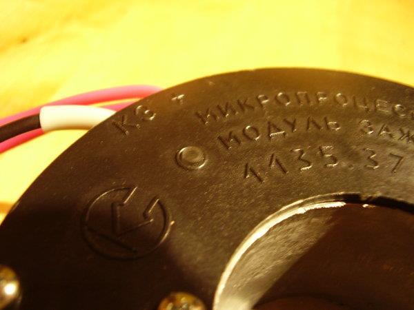
 Gap Magnetic Sensor Module: 135.3734 Ignition Coil 135.")
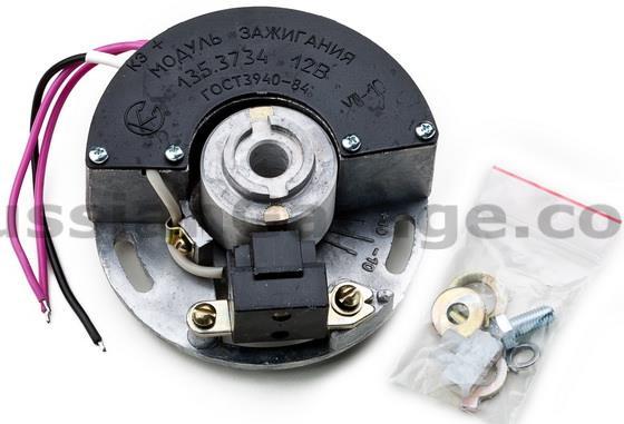
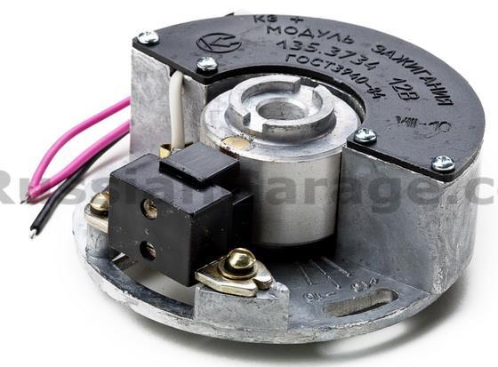
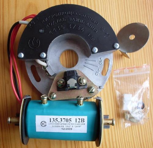
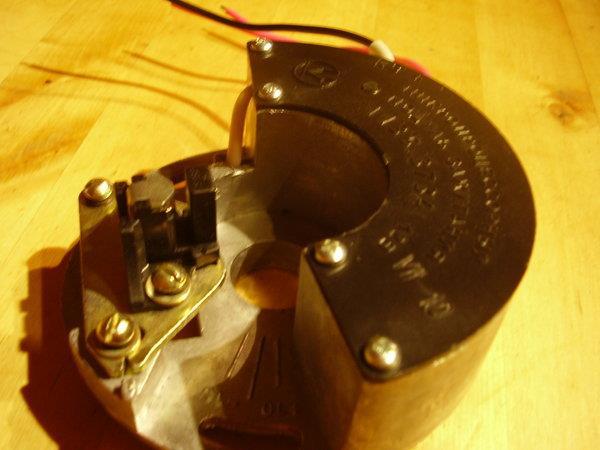
31 Type II Ignition (1997 or 1998) Designated BC3 (BSZ / БСЗ) Made in USSR: SOAKE (Stary Oskol Plant of Electrical Equipment) Replace All Urals & Dneprs with Centrifugal-Advance Ignition (PM-302) Electronics Inside Small C-shaped Module Mounted under Front Ignition Cover, Across from Magnetic Rotor Sensor Ignition Coil with Higher Output Voltage: (Replaced B-201 and B-204) Components in Module Potted (encased in epoxy) to Protect Against Vibration Module Had Issues with Heat Build-Up Located Entirely within Front Ignition Cover Spark Plugs: NGK BP7HS with mm ( ) Gap Magnetic Sensor Module: Ignition Coil Ural Types II/III electronic ignitions were originally designed as after-market for Ural, but also fit Dnepr. Urals approved for sale in the USA (1994) were approved for contact-less point ignition. Bikes with the manual advance/retard timing unit (PM-05) don t have a threaded 31 hole in the end of the cam for the rotor bolt of the electronic ignition.
 Sensor 2 - Rotor with Permanent Magnets 3 - Electronic")


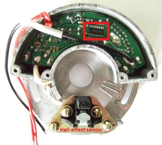
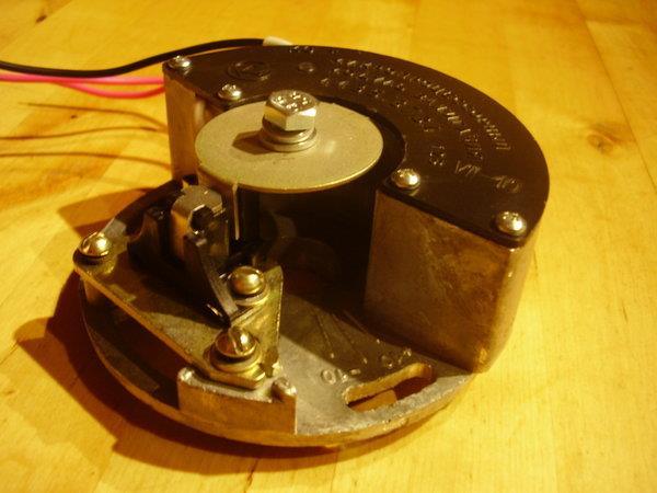
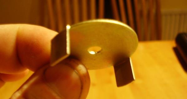
32 Type II Ignition (BSC/BC3/BSZ) Magnetic Flux Interacts with Hall Sensor 1 - Hall-Effect (Inductive) Sensor 2 - Rotor with Permanent Magnets 3 - Electronic Commutator (breaker points) 4 - Rotating Hall-Effect Sensor Screen 5 - Hall-Effect Probe 6 - Base for Electronic Commutator 7 - Timing Marks (grooves to adjust timing) The electronic ignition relies on a Hall-effect magnetic sensor to provide a timing signal to the electronic commutator (equivalent to breaker points). 32


33 Type II Ural / Dnepr (6 to 16-Volt) ural-hamburg.de 33


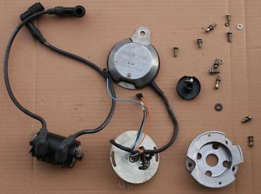
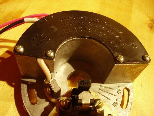
34 Type III (mid-1998) Designated MSK (Microprocessor Ignition System) Made in CIS: SOAKE (Stary Oskol Plant of Electrical Equipment) Shortly After Type II Appeared, Replaced with Type III Same Appearance as Type II Ignition System Located Entirely within Front Ignition Cover Circuit Board Modified to Prevent Heat Failure Partway into Production Span of Type III, a High-Output Coil Was Mounted Outside the Front Engine Cover for Cooling System Very Reliable Spark Plugs: NGK BP7HS with mm ( ) Gap Ignition Coil: Magnetic Sensor Leads to Ignition Coil The ignition coil is in the front compartment. There is a horseshoe-shaped electronics, a pick-up and a metal rotor with magnets embedded in it on the 34 end of the camshaft that held in place by a D-washer that is made of "unobtainium."
35 Type III Contact-less Electronic Ignition 35
 Lower View of Front Ignition Compartment Showing Key Washer Upper View of Front Ignition Compartment Showing")
.")
36 Type III Ignition (Heavy Mass of Rotor Causes Key-Wear) Ignition Coil ( ) Lower View of Front Ignition Compartment Showing Key Washer Upper View of Front Ignition Compartment Showing Ignition Coil The washer "keying" the rotor to the camshaft can wear over time allowing play in the rotor. The engine will run poorly (backfiring, running on one side better than other, poor performance). Riders 36 need to check for security of the rotor s steel slugs and the magnets.

37 Type IV (2002) (Bill Glaser's myural.com site and 2002 Ural Manual) MSZ UKTUS Ignition on CMSI Introduced in 2002 with Adoption of 750cc Engine Located Entirely within Front Engine Cover Massive Pot-Metal Rotor Replaced by Lighter Stamped Steel Unit with Notches Uses Hall-Effect Magnetic Sensor Mounted in Module Cover Newer-Design, High-Output Coil Mounted inside Front Ignition Cover Built-In Diagnostic LED Simplified Timing Sparking Voltage: 17-kilovolt (kv) Operating Temperature: -50 to +100 C Ignition Coil Best with Also Works with B-201 and B-204 Current Load: Engine Off: 0.10 to 0.15-Amp Self-cleaning Contacts Engine On (200-6,000 rpm): 1.5-Amp Supply Voltage: Nominal 12-Volt 7-to-16-Volt Operation The silver "hockey puck of doom," with the blinking LED, was located 37 inside the front engine compartment and suffered from heat build-up.
 3 IMZ-8.108-17071 301262.008 Rotor 4 IMZ-8.108-17002 687422.009 Hall-Effect Magnetic Sensor (Pick-up) 5 IMZ-8.108-17135 731151.")
38 Type IV Microprocessor Ignition System (2002) TYPE IV COM-2 (CDI) Microprocessor Ignition System, IMZ CDI (Capacitor Discharge Ignition) 2 IMZ KMCZ Ignition Coil (5-Ohm) 3 IMZ Rotor 4 IMZ Hall-Effect Magnetic Sensor (Pick-up) 5 IMZ Casing 6 IMZ Microprocessor Ignition System (MAS) If the microprocessor (round silver puck with LED) is under the front ignition cover you have a Type IV, if the puck/led is outside you have a Type V. 38
 TYPE IV 135.3734.")
39 Type IV for 12-Volt Ural/Dnepr (ural-hamburg.de) TYPE IV COM-2 (CDI) 39
 No Swaged Seam On Newer Model Swaged Seam Left: Early-Manufactured, Two-Piece, Swaged-Joint Interrupter; Shoulder Meeting Round")
 up to 2006 (MSZ): IMZ-8.1037-17220-20 from 2007: IMZ-8.")
 from")
40 Type IV/V Rotor Evolution: Two-Piece to One-Piece Rotor ( No Swaged Seam On Newer Model Swaged Seam Left: Early-Manufactured, Two-Piece, Swaged-Joint Interrupter; Shoulder Meeting Round Skirt Right: Newer One-Piece, Machined Interrupter Left: Two-piece, with Swaged Seam on Back Right: One-piece; Devoid of Swaged Seam Ignition Rotor (750cc) up to 2006 (MSZ): IMZ from 2007: IMZ Note: New style, one-piece rotors are available for Type IV & V electronic ignition. Type V Ignition Rotor with Swaged seam The two-piece rotor will fail, causing timing issues (slip, throwing timing out the window) from a slight miss to not running. Replace the two-piece with the one-piece rotor! 40 The ignition rotor was changed to a new "one-piece type" in 2007.
 UKTUS Ignition Basically Type IV Split into Two Units: Magnetic Sensor and Electronic Commutator (Puck) Magnetic Sensor (Pick-Up) and Interrupter Located in Front Ignition Cover External")

41 Type V Ignition System (2004) ( UKTUS Ignition Basically Type IV Split into Two Units: Magnetic Sensor and Electronic Commutator (Puck) Magnetic Sensor (Pick-Up) and Interrupter Located in Front Ignition Cover External Puck: Electronics Moved into Air-stream for Cooling Timing LED Now Visible without Disassembly of Front Ignition Cover Type IV Failed to Advance Timing Once Engine above rpm Possible Problems under Hot Conditions Timing Adjustment: Bring up the Full-Advance Timing Mark on Flywheel and Rotate Sensor Unit until LED Illuminates Ignition Coil Magnetic Sensor Locking Screws The silver "hockey puck" was moved to the frame near the front right side of the gas tank, with an LED that blinks when the engine is running. 41 The coil and rotor/pick-up unit remained inside the front compartment.


42 Type V Ignition 2004 Ural Patrol 42

43 Type V Russian Ignition (from a 2005 Retro) 43

44 Contact-Less Electronic Ignition: Model
 New Type Has LED for Timing New Rotor Made of Very Light Flat Plate Fixes Old Problem of Rotor Breaking-Up or Chattering and Damaging Tabbed Washer Potential for New Problem, as There Is No Way")
45 New Microprocessor-Based Electric Ignition System Model (Ignitionhttp://seriousbill.multiply.com) New Type Has LED for Timing New Rotor Made of Very Light Flat Plate Fixes Old Problem of Rotor Breaking-Up or Chattering and Damaging Tabbed Washer Potential for New Problem, as There Is No Way to Positively Lock the Rotor in Position, So It Can Slip Careful Use of Loctite and Proper Tightening of Screw Keeps Things In Place 45


46 Improved Version replacing Old Model : Model: (5 to 12-Volts) 46


47 New Model (Ignitionhttp://seriousbill.multiply.com) 47
 One-Piece Rotor")

48 Ducati Ignition System (2006) IMZ : Conversion Kit Ignition by Ducati Energia (not affiliated with Ducati Motorcycles) One-Piece Rotor Standard Standard with January 06 Ural Production Not much in the front compartment other than the interrupter and the pickup. The ignition coil is a small square box mounted under the front of the gas tank and the spark plug wires go to that box. 48 The brain box for the Ducati is placed near the battery.


49 Ducati Ignition System Ignition Coil 49

50 Ducati Ignition System Ducati Ignition assembly IMZ Pick Up Without Support Plate, Includes all brackets and hardware necessary to install ignition system Support plate for pickup 'IMZ Digital CDI Ignition Coil Rubber Holder Support plate for Ignition Support bracket for CDI Ignition mounting set for pickup High-Voltage Cables with Caps Ignition Coil with Spark Plug Caps IMZ IMZ IMZ Ducati, introduced in 2006 Urals, has proven to be a reliable electronic 50 (contact-less) ignition system for Urals and retro-fitted Dneprs.
 Retrofit Ducati or Types II-thru-V Russian Ignitions Two Ignition Curves Loaded into Processor")
 Simple")

51 Ural Power Arc Ignition System Retrofit Ducati or Types II-thru-V Russian Ignitions Two Ignition Curves Loaded into Processor Standard Ural/Ducati Curve Second Curve Accessed via Momentary Toggle Switch Coil Receives No Current if Engine Not Running No hot Coil Multi-Spark Feature (fires three times each firing cycle) Simple Installation Built -In LED Timing Light Tachometer Lead and Rev-Limiter Available Exclusively Distributed by Raceway Services Raceway Services offers the Power Arc System to cure the problems of previous Type II thru V ignition systems 51 and provide improved perfomance.
 Electronic Ignition for Early Soviet")


52 Powerdynamo Ignition System ( Electronic Ignition for Early Soviet 6-Volt M-72 Kit Contains: Trigger Unit / Rotor Unit Advance Unit AC/DC Converter Twin Ignition Coil / HT-Cable Incidentals 52 The distributor cap and rotor are taken off and are no longer used.
53 Ignition Coils Ignition Coils for Contact (Breaker) Systems KM-01 Coil PM-05 Breaker/ Distributor IG-4048 Coil PM-05 Breaker/ Distributor B11 Coil PM-05 Breaker/ Distributor B2B Coil PM-05 or PM-11 Breaker/ Distributor B201 Coil PM-302 Breaker/ Distributor B204 Coil PM-302/302A Breaker/ Distributor Primary Winding Resistance of 5-Ohms Ignition Coils for Contact-Less (Electronic) Systems Type I to- Type V Ignition Systems Most Electronic Ignition Coils Have 1 -to- 2-Ohms Type I Ignition Coil: 5-Ohms Types II, III, IV and V Ignition Coils: 1 -to- 2-Ohms Ducati Ignition System Ural Power Arc Ignition System Each ignition coil is associated (paired) with a distinctive, corresponding ignition system. 53
 was the KM-01, which was replaced with the IG-4085B.")
54 The first ignition coil used on a heavy Russian motorcycle (M-72) was the KM-01, which was replaced with the IG-4085B. 54

 winding is common to the secondary (high-voltage) winding.")
55 KM-01 6-Volt Ignition Coil for M Case 2. Mounting Bracket 3. Primary Interrupted Winding 4. Hi-Voltage Secondary Output 5. Mounting Bracket 6. Primary Interrupted Winding 7. Insulator 8. Hi-Voltage Output to Distributor and Spark Plugs The ignition coil is nothing more than a transformer. One end of the primary (low-voltage) winding is common to the secondary (high-voltage) winding. The beginning of the primary winding is connected thru the ignition switch connected to the battery, and ends where the contact breaker is closed to ground (mass). 55
 for Ural M-72 and Dnepr K-750,")


56 IG-4085B and B2B (Б2Б) Ignition Coils (6-Volt) for Ural M-72 and Dnepr K-750, MB-750, MB-650, Dnepr 650, M-72 IG-4085B Ignition Coil B2B Ignition Coil 1 - Low-Voltage (6-Volt) Terminals to Battery and PM-05 Breaker, 2 - Plastic Cap, 3- Magnetic Core, 4- Low-Voltage Winding, 5 Shield, 6 Insulator, 7 - High- Voltage Winding, 8 Case, 9 - High-Voltage output to PM-05 Distributor The IG-4085B and B2B coils later replaced the KM


57 B201 (Б201, 6-Volt) Ignition Coil (катушка зажигания) for Ural/Dnepr K-750, MB-750, MB-650, Dnepr 650, M -72 Arc-Gap High-Voltage Output Terminals Primary (Low-Voltage) Winding Mounting Ear Input Voltage: 6-Volts Gap between Discharges: 9 mm Primary Winding: 300 turns / dia mm Wire Wound on 3 Layers Secondary Winding: 19,000 ±200 turns / dia mm Wire Wound in 2 Sections Safety Arc-Gap The B201 became the standard ignition coil for 6-Volt Urals and Dneprs. 57


58 B201A (Бобина 6В Б201А) 6-Volt Ignition Coil for Ural, Dnepr Motorcycles Safety Arc-Gap High-Voltage Output Terminals Mounting Ear Primary Winding Terminal Primary Winding Terminal The B201A replaced the B201 ignition coil on Ural/Dnepr motorcycles. 58


59 Б204 (B204) Ignition Coil 12-Volt for Ural/Dnepr Primary Winding Terminal Safety Arc-Gap Safety Arc-Gap High-Voltage Output Terminals Both plugs fire simultaneously on the left and right cylinders, one spark being formed when the compression stroke 59 terminates in one cylinder and the other during the exhaust stroke.

60 Arc Gaps on B201 and B204 Ignition Coils Be careful not to bend or alter he gaps! The ignition coil is double-ended with two spark safety gaps, which were set at 9 mm (0.355 ). 60

61 Ignition Coil 12-Volt for Type II thru Type V Ignition Systems High-Voltage Output Terminals Primary Winding Terminal Resistance: 5-Ohms Safety Arc-Gap Mounting Ear The later replaced the B204 as more contact-less (electronic) ignition systems were developed. 61
Russian Headlight Assemblies
 Russian Headlight Assemblies Part I: Headlight Cavity, Early Central Switch and Speedometer (Also See Russian Flasher / Directional Lights) Ernie Franke eafranke@tampabay.rr.com (09/2011) Early Ignition
Ural and Dnepr Generators and Alternators Generator. Ernie Franke 01/2011
 Ural and Dnepr s and Alternators Part II: Г-11 (G-11) Ernie Franke eafranke@tampabay.rr.com 01/2011 Types of s/alternators for Ural (Урал( Урал) ) and Dnepr (Днепр)( (01/11) / Alternator Г-11 (G-11) (P/N:
Russian Regulators: Part II. for the Generator. Ernie Franke
 Russian Regulators: Part II PP-302 / -302A for the Watt 65-Watt Ernie Franke eafranke@tampabay.rr.com 6-Volt Electro-Magnetic (Relay-Type) Regulator (PP-302/ 302/-302A) 302A) for the 10-Amp Background
Russian Turn-Signals and Flasher Relays
 Russian Turn-Signals and Flasher Relays (Реле-прерыватель указателей поворотов) History of Flashers/Blinkers (Turn-Signals) on Russian Motorcycles Old, New and Newest Wiring Diagrams Where is the Flasher
Russian Regulators: Part I. The Early Years. for the. 11A 7-Amp Generator. Ernie Franke
 Russian Regulators: Part I The Early Years PP-1/ 1/-30/ 30/-3131 & -31A Г-11/ 11/-11A for the 11A 7-Amp Ernie Franke eafranke@tampabay tampabay.rr.com 6-Volt Electro-Magnetic (Relay-Type) Regulator (PP-1/
Russian Motorcycle Schematics and Wiring Diagrams Part XII: Dnepr Schematics, Wiring Diagrams and Part Lists
 Russian Motorcycle Schematics and Wiring Diagrams Part XII: Dnepr Schematics, Wiring Diagrams and Part Lists Ernie Franke eafranke@tampabay.rr.com 11 / 2017 Differing Electrical Schematics on the Same
Ignition Systems for. Russian Motorcycles
 Ignition Systems for Russian Motorcycles (Part V: Setting Timing) Ernie Franke eafranke@tampabay tampabay.rr.com (01/2010) Setting Timing on Russian Motorcycle Ignition Systems Setting Timing for Manual
Ural (Урал) - Dnepr (Днепр) Part XXV: Master Battery Ground Switch (ВЫКЛЮЧаТелЬ массы) Ernie Franke 09 / 2017
 - Dnepr (Днепр) Part XXV: Master Battery Ground Switch (ВЫКЛЮЧаТелЬ массы) Ernie Franke 09 / 2017") Ural (Урал) - Dnepr (Днепр) Part XXV: Master Battery Ground (ВЫКЛЮЧаТелЬ массы) Ernie Franke 09 / 2017 eafranke@tampabay.rr.com Master Battery Ground (ВЫКЛЮЧаТелЬ массы) Disconnects All Electrical Systems
Ural (Урал) - Dnepr (Днепр) Part XXV: Master Battery Ground (ВЫКЛЮЧаТелЬ массы) Ernie Franke 09 / 2017 eafranke@tampabay.rr.com Master Battery Ground (ВЫКЛЮЧаТелЬ массы) Disconnects All Electrical Systems
Part 2: Russian Motorcycle Rear-Wheel Plungers and Swing-Arms
 Ural (Урал( Урал) - Dnepr (Днепр( Днепр) Part : Russian Motorcycle Rear-Wheel Plungers and Swing-Arms (Also See Part : Russian Motorcycle Swing-Arms, Part 3: Sidecar Swing-Arms, Part 4: Swing-Arm Components
CHAPTER 6 IGNITION SYSTEM
 CHAPTER 6 CHAPTER 6 IGNITION SYSTEM CONTENTS PAGE Faraday s Law 02 The magneto System 04 Dynamo/Alternator System 06 Distributor 08 Electronic System 10 Spark Plugs 12 IGNITION SYSTEM Faraday s Law The
Military Accessories. Russian Motorcycles
 Military Accessories for Russian Motorcycles Part VIII: Driving Lights and Spot-Lights Ernie Franke eafranke@tampabay.rr.com 03/2010 Driving Lights and Spot-Lights Generator/Alternator Limitations on Lighting
Battery powered ignition
 Battery powered ignition A typical battery powered ignition uses a transformer, a several switching devices, and a power source. The power source is the battery. Battery powered ignition The first switch
Ural (Урал) - Dnepr (Днепр) Part VII: Muffler Evolution
 - Dnepr (Днепр) Part VII: Muffler Evolution") Ural (Урал) - Dnepr (Днепр) Mufflers for Russian Motorcycles with Sidecars Part VII: Muffler Evolution ) Ernie Franke eafranke@tampabay.rr.com 09 / 2017 Review of Mufflers on Russian Sidecars Information
Ural (Урал) - Dnepr (Днепр) Mufflers for Russian Motorcycles with Sidecars Part VII: Muffler Evolution ) Ernie Franke eafranke@tampabay.rr.com 09 / 2017 Review of Mufflers on Russian Sidecars Information
IGNITION/HEADLAMP SWITCH
 IGNITION/HEADLAMP SWITCH DO NOT modify the ignition/headlamp switch wiring to circumvent the automatic-on headlamp feature. Visibility is a major concern for motorcyclists. Failure to have proper headlamp
AUTOMOTIVE ENGINEERING SECTION
 PURPOSE OF IGNITION SYSTEM The ignition system supplies high-voltage surges as high as 47,000 volts (in some electronic systems) to the spark plugs in the engine cylinders. These surges produce electric
Ural (Урал( Днепр) Mufflers for Russian Motorcycles Part 2: Muffler Components. Ernie Franke 12 / 2012
 Mufflers for Russian Motorcycles Part 2: Muffler Components. Ernie Franke 12 / 2012") Ural (Урал( Урал) - Dnepr (Днепр( Днепр) Mufflers for Russian Motorcycles Part 2: Muffler Components (Also See Part 1: Muffler Introduction, Part 3: Installation of Modtop Muffler, Part 4: After-Market
Ural (Урал( Урал) - Dnepr (Днепр( Днепр) Mufflers for Russian Motorcycles Part 2: Muffler Components (Also See Part 1: Muffler Introduction, Part 3: Installation of Modtop Muffler, Part 4: After-Market
Electrical Systems. Introduction
 Electrical Systems Figure 1. Major Components of the Car s Electrical System Introduction Electricity is used in nearly all systems of the automobile (Figure 1). It is much easier to understand what electricity
Sensors & Controls. Everything you wanted to know about gas engine ignition technology but were too afraid to ask.
 Everything you wanted to know about gas engine ignition technology but were too afraid to ask. Contents 1. Introducing Electronic Ignition 2. Inductive Ignition 3. Capacitor Discharge Ignition 4. CDI vs
Russian Motorcycle Evolution
 Ural (Урал( Урал) - Dnepr (Днепр( Днепр) Russian Motorcycle Evolution Part I: Engines (See Also Part II: Russian Generators/Alternators Part III: Russian Ignition Systems and Part IV: Russian Carburetors
1.0 Installation Wiring
 1.0 Installation Wiring DX Firebox is designed to be an electronic replacement for Pontiac & Ford buzz coils when operated on DC. Installation may be positive or negative ground. Simply observe the RED
Adding Fog Lights. Russian Motorcycles. Ernie Franke
 Adding Fog Lights to Russian Motorcycles Ernie Franke 0/0 eafranke@tampabay tampabayrrcom Adding Fog Lights to Russian Motorcycles oking for Something that Would Increase Conspicuity (visibility or noticeability)
Russian Motorcycle (Ural) Part XXXI-5: Full-Time 1WD with Engageable 2WD (non-diff)
 Part XXXI-5: Full-Time 1WD with Engageable 2WD (non-diff)") Russian Motorcycle (Ural) Part XXXI-5: Full-Time 1WD with Engageable 2WD (non-diff) (Also See Part XXXI: Drive Chain Evolution, Part XXXI-1: One-Wheel Drive (1WD), Part XXXI-2: Two-Wheel Drive (2WD), Part
Russian Motorcycle (Ural) Part XXXI-5: Full-Time 1WD with Engageable 2WD (non-diff) (Also See Part XXXI: Drive Chain Evolution, Part XXXI-1: One-Wheel Drive (1WD), Part XXXI-2: Two-Wheel Drive (2WD), Part
Contents. DX Ignition Page 2
 Contents 1.0 Intent 2.0 Specifications 3.0 Installation 4.0 Operation Precautions 5.0 Repair 6.0 Parts List 7.0 Glossary of Terms 8.0 Contact Information DX Ignition Page 2 1.0 Intent The purpose of this
INFORMATION. covering use of Ammeter and Voltmeter ON and 1915 Model Six-54 Electrical System
 INFORMATION covering use of Ammeter and Voltmeter ON- 1914 and 1915 Model Six-54 Electrical System Hudson Motor Car Company Detroit, Michigan, IX S. A USE OF AMMETER ON 1914 AND 1915 MODEL SIX-54 With
(2WD) with non-locking Differential
 with non-locking Differential") Ural (Урал( Урал) - Dnepr (Днепр( Днепр) Russian Motorcycle Part 3B: Full-Time Two-Wheel Drive (2WD) with non-locking Differential (MT-2 / MT-6 / MB-650M / MB-650M / Ural Sportsman ) (See Also Part 3A:
Ural (Урал( Урал) - Dnepr (Днепр( Днепр) Russian Motorcycle Part 3B: Full-Time Two-Wheel Drive (2WD) with non-locking Differential (MT-2 / MT-6 / MB-650M / MB-650M / Ural Sportsman ) (See Also Part 3A:
Днепр) Russian Motorcycle Carburetors
 Russian Motorcycle Carburetors") Ural (Урал( Урал) - Dnepr (Днепр( Днепр) Russian Motorcycle Carburetors Part 1: Introduction- Carburetor (Карбюраторыъ( Карбюраторыъ) Evolution for Russian Sidecars Ernie Franke eafranke@tampabay.rr.com
Ural (Урал( Урал) - Dnepr (Днепр( Днепр) Russian Motorcycle Carburetors Part 1: Introduction- Carburetor (Карбюраторыъ( Карбюраторыъ) Evolution for Russian Sidecars Ernie Franke eafranke@tampabay.rr.com
Part XVIII: Russian Motorcycle Speedometer Evolution
 Part XVIII: Russian Motorcycle Speedometer Evolution (also see Russian Headlight Assemblies) Ernie Franke eafranke@tampabay.rr.com 09 / 2017 Speedometer / Odometer Overview and Notes Part I: Three Types
Contacts The moveable contact, which is the one affected by the armature is sometimes referred to as the hinge contact.
 Relays & Wiring 101 Basically, a relay is an electrically operated, remotely controlled switch. A simple electromagnetic relay is an adaptation of an electromagnet. It consists of a coil of wire surrounding
Military Accessories. Russian Motorcycles
 Military Accessories for Russian Motorcycles Part VII: Black-Out Lights Ernie Franke eafranke@tampabay.rr.com 03/2010 Black-Out Lights for Russian Motorcycles What are Black-Out Lights? Blackout Lights
Ural (Урал) - Dnepr (Днепр) Russian Motorcycle. Part XIV: Plunger, Swing-Arm and Torsion Bar Evolution
 - Dnepr (Днепр) Russian Motorcycle. Part XIV: Plunger, Swing-Arm and Torsion Bar Evolution") Ural (Урал) - Dnepr (Днепр) Russian Motorcycle Part XIV: Plunger, Swing-Arm and Torsion Bar Evolution ( Ernie Franke eafranke@tampabay.rr.com 09 / 2017 Swing-Arms and Torsion Bars for Heavy Russian Motorcycles
Ural (Урал) - Dnepr (Днепр) Russian Motorcycle Part XIV: Plunger, Swing-Arm and Torsion Bar Evolution ( Ernie Franke eafranke@tampabay.rr.com 09 / 2017 Swing-Arms and Torsion Bars for Heavy Russian Motorcycles
IGNITION SYSTEM COMPONENTS AND OPERATION
 69 IGNITION SYSTEM COMPONENTS AND OPERATION Figure 69-1 A point-type distributor from a hot rod being tested on a distributor machine. WARNING: The spark from an ignition coil is strong enough to cause
Russian Motorcycle Part 1: Overall Drive-Chain
 Ural (Урал( Урал) - Dnepr (Днепр( Днепр) Russian Motorcycle Part 1: Overall Drive-Chain (Also See Part 2: One-Wheel Drive (1WD), Part 3: Two-Wheel Drive (2WD), Part 4: Gears and Gear Ratios, Part 5: Disassembly
ATASA 5 th. ATASA 5 TH Study Guide Chapter 27 Pages Ignition Systems 68 Points. Please Read the Summary
 ATASA 5 TH Study Guide Chapter 27 Pages 810 835 68 Points Please Read the Summary Before We Begin Keeping in mind the Career Cluster of Transportation, Distribution & Logistics Ask yourself: What careers
Chrysler Electronic Ignition System
 1 of 11 1/6/2010 11:02 PM Chrysler Electronic Ignition System Classic Winnebago's Post by: DaveVA78Chieftain on August 13, 2009, 10:15 PM Components The Chrysler Electronic Ignition System consists of
THE FOURTH STATE. Gaining a universal insight into the diagnosis of automotive ignition systems. By: Bernie Thompson
 THE FOURTH STATE Gaining a universal insight into the diagnosis of automotive ignition systems By: Bernie Thompson Did you know that the forth state of matter powers the spark ignition internal combustion
Ignition Installation Troubleshooting Tips/Frequently-Asked Questions
 Ignition Installation Troubleshooting Tips/Frequently-Asked Questions Warning: Reversing the red and black ignition wires will destroy the ignition module and void the warranty. The Hot-Spark module s
INTRODUCTION Principle
 DC Generators INTRODUCTION A generator is a machine that converts mechanical energy into electrical energy by using the principle of magnetic induction. Principle Whenever a conductor is moved within a
Ignition System Fundamentals
 Ignition System Fundamentals Chapter 37 Objectives Describe the functions of ignition system parts Explain the operation of points, electronic, and computer ignition systems Give an overview of the different
ACCEL Distributor Model #A557
 FORM 1627 REV1 INSTALLATION INSTRUCTIONS ACCEL Distributor Model #A557 CAUTION: CAREFULLY READ INSTRUCTIONS BEFORE PROCEEDING. NOT LEGAL FOR USE OR SALE ON POLLUTION CONTROLLED VECHICLES OVERVIEW ACCEL
INDEX Section Page Number Remarks
 INDEX Section Page Number Remarks Synchronous Alternators 2 4 General Fault Finding Capacitors 5 6 Fault Finding & Testing Diodes,Varistors, EMC capacitors & Recifiers 7 10 Fault Finding & Testing Rotors
The Physics of the Automotive Ignition System
 I. Introduction This laboratory exercise explores the physics of automotive ignition systems used on vehicles for about half a century until the 1980 s, and introduces more modern transistorized systems.
Russian Motorcycle Gas Tanks
 Russian Motorcycle Gas Tanks Part II: Knee Grips (See Also Part I: Gas Tanks, Part III: Gas Tank Removal, Part IV: Petcocks) Ernie Franke eafranke@tampabay.rr.com July 2014 Rubber Knee Grips for 7210171-Б
Днепр) Russian Motorcycle
 Russian Motorcycle") Ural (Урал( Урал) - Dnepr (Днепр( Днепр) Russian Motorcycle Part 3D: Full-Time WD with Engageable 2WD (non-diff) (Ural) (See Also Part 3A: Locking versus non-locking Differential, Part 3B: Full-Time 2WD
Ural (Урал( Урал) - Dnepr (Днепр( Днепр) Russian Motorcycle Part 3D: Full-Time WD with Engageable 2WD (non-diff) (Ural) (See Also Part 3A: Locking versus non-locking Differential, Part 3B: Full-Time 2WD
INSTALLATION INSTRUCTIONS for HI-1 and HI-2 MOTORCYCLE IGNITIONS. Part Numbers and INTRODUCTION COIL AND SPARK PLUG CABLE CONSIDERATIONS
 INSTALLATION INSTRUCTIONS for HI- and HI- MOTORCYCLE S Part Numbers 8-000 and 8-000 CAUTION: READ INSTRUCTIONS CAREFULLY BEFORE STARTING INSTALLATION INTRODUCTION Crane HI- and HI- ignition systems are
CAUTION: READ INSTRUCTIONS CAREFULLY BEFORE STARTING INSTALLATION
 V-Twin MFG. VT No. 32-9500 V-TECH 1 IGNITION KIT, SINGLE FIRE FITS EV SHOVEL, XL THRU 1997 VT No. 32-9503 V-TECH 1 IGNITION KIT, SINGLE FIRE FITS EV, SHOVEL, XL, WITH COIL AND WIRES This is a custom application
Electronic Ignition for HONDA CB Fours
 Electronic Ignition for HONDA CB350-400-500-550-750 Fours THE Accent SYSTEM The use of electronic ignition systems on motorcycles has shown a good performance over the last decades. Unfortunately, older
Tempest Tech-Tip 0813
 August 2013 Tempest Tech-Tip 0813 Light My Fire Background Without a good spark, spark plugs can t get the job done well. How do you keep good sparks coming, so your spark plugs can light your fire with
Just what is an alternator?
 Just what is an alternator? An alternator is the device used to produce the electricity the car needs to run and to keep the battery charged. The battery is the heart of your electrical system. But you
1 Function Scope of Delivery Mounting Electrical Connections Initial Setup Troubleshooting...
 Elektronik Sachse MHP GmbH & Co. KG Installation Manual Digital Ignition ZDG 3.23 (Ducati Mille) Item: Z73 version: f4feb00 Contents 1 Function.......................................................................
Unit AE01K Knowledge of Locating and Correcting Simple Electrical Faults in the Automotive Workplace
 Assessment Requirements Unit AE01K Knowledge of Locating and Correcting Simple Electrical Faults in the Automotive Workplace Content: Basic electrical principles a. Explain the direction of current flow
Horns, Wiper, and Washer System Operation
 14 Horns, Wiper, and Washer System Operation LEARNING OBJECTIVES Upon completion and review of this chapter, you should be able to: Explain the operation of an automotive horn. Identify the different types
Part III: Installation of Black Modtop Mufflers on 2003 Ural Patrol
 Ural (Урал( Урал) - Dnepr (Днепр( Днепр) Mufflers for Russian Motorcycles with Sidecars Part III: Installation of Black Modtop Mufflers on 2003 Ural Patrol (Also See Part 1: Muffler Introduction, Part
To avoid a short cut please file off the right half of the Y-hole flange.
 Fitting instructions for automatic alternator controller for Moto Guzzi with Bosch alternator 1. alternator modification - 2. Fitting - 3. adjustment (ignition only) First remove the connector block of
STARTING SYSTEMS 8B - 1 STARTING SYSTEMS CONTENTS
 TJ STARTING SYSTEMS 8B - 1 STARTING SYSTEMS CONTENTS page DESCRIPTION AND OPERATION STARTER MOTOR... 2 STARTER RELAY... 3 STARTING SYSTEM... 1 DIAGNOSIS AND TESTING STARTER MOTOR... 8 STARTER MOTOR NOISE
MSD Zero-Cross Distributor Chevrolet - PN 83971
 MSD Zero-Cross Distributor Chevrolet - PN 83971 Parts Included: 1 Distributor 1 Gasket 1 Hold Down & Hardware 1 Gear Lubricant 2 O-Rings IMPORTANT The Separate Pickup Zero-Cross Distributors use two completely
AccuSpark. Fitting and Information Guide For. Modules Distributors coils Tools. Modern Ignition for Classic cars
 AccuSpark Modern Ignition for Classic cars Fitting and Information Guide For Modules Distributors coils Tools www.accuspark.co.uk 1 Before fitting AccuSpark Distributors AccuSpark electronic ignition kit.
ADDIS ABABA UNIVERSITY INSTITUTE OF TECHNOLOGY
 1 INTERNAL COMBUSTION ENGINES ADDIS ABABA UNIVERSITY INSTITUTE OF TECHNOLOGY MECHANICAL ENGINEERING DEPARTMENT DIVISON OF THERMAL AND ENERGY CONVERSION IC Engine Fundamentals 2 Engine Systems An engine
UNIT 4 IGNITION SYSTEMS
 UNIT 4 IGNITION SYSTEMS Ignition Systems Structure 4.1 Introduction Objectives 4.2 Ignition System Types 4.3 Comparison between Battery and Magneto Ignition System 4.4 Drawbacks (Disadvantages) of Conventional
ELECTRICAL. Contents - Wiring Diagrams
 Contents - Wiring Diagrams T-Bar (Floating Deck - Hydro)............................................ 8-16 T-Bar (Fixed Deck - Gear)............................................... 8-17 T-Bar (Fixed Deck
Automotive Parts. Charging & Starting Systems
 Automotive Parts Charging & Starting Systems Charging Systems Output voltage kept to about 2 volts higher than battery voltage Controlled by varying current into rotor field winding (voltage regulator
Урал) - Dnepr (Днепр) Russian Motorcycle Carburetors
 - Dnepr (Днепр) Russian Motorcycle Carburetors") Ural (Урал( Урал) - Dnepr (Днепр) Russian Motorcycle Carburetors Part 8A: Adjustment and Overhaul of the Pekar K-65 Carburetors (see also Part 8-8 K-65 Carburetor and Part 8B- Setting Up K-65 K Carbs)
Ural (Урал( Урал) - Dnepr (Днепр) Russian Motorcycle Carburetors Part 8A: Adjustment and Overhaul of the Pekar K-65 Carburetors (see also Part 8-8 K-65 Carburetor and Part 8B- Setting Up K-65 K Carbs)
SHORT-STOP. Electronic Motor Brake Type G. Instructions and Setup Manual
 Electronic Motor Brake Type G Instructions and Setup Manual Table of Contents Table of Contents Electronic Motor Brake Type G... 1 1. INTRODUCTION... 2 2. DESCRIPTION AND APPLICATIONS... 2 3. SAFETY NOTES...
ABB ! CAUTION. Type KRV Directional Overcurrent Relay E 1.0 APPLICATION 2.0 CONSTRUCTION AND OPERATION. Instruction Leaflet
 ABB Instruction Leaflet 41-137.2E Effective: February 1994 Supersedes I.L. 41-137.2D, Dated February 1973 ( )Denotes Change Since Previous Issue. Type KRV Directional Before putting relays into service,
UNIT 2. INTRODUCTION TO DC GENERATOR (Part 1) OBJECTIVES. General Objective
 OBJECTIVES. General Objective") DC GENERATOR (Part 1) E2063/ Unit 2/ 1 UNIT 2 INTRODUCTION TO DC GENERATOR (Part 1) OBJECTIVES General Objective : To apply the basic principle of DC generator, construction principle and types of DC generator.
DC GENERATOR (Part 1) E2063/ Unit 2/ 1 UNIT 2 INTRODUCTION TO DC GENERATOR (Part 1) OBJECTIVES General Objective : To apply the basic principle of DC generator, construction principle and types of DC generator.
C. Figure 1. CA-16 Front View Figure 2. CA-16 Rear View
 Figure 1. CA-16 Front View Figure 2. CA-16 Rear View 2 2.1. Restraint Elements Each restraint element consists of an E laminated electromagnet with two primary coils and a secondary coil on its center
HIRTH 2703 Carburated - 55 hp
 HIRTH 2703 Carburated - 55 hp The 2703 V is an air cooled, piston controlled 2-cylinder-inline-2-stroke engine with one or two carburetors and Nikasil coated cylinders. It has one of the highest power
1 Function Scope of Delivery Mounting Electrical Connections Initial Setup Troubleshooting...
 SACHSE Elektronik Sachse MHP GmbH & Co. KG Installation Manual Digital Ignition ZDG 3.23 (Honda CB72/ 77) Item: Z06-CB72 version: 62aa227 Contents 1 Function.......................................................................
STK-010 BSA: B25, B40, B44, B50, C15, Royal Enfield Bullet
 STK-010 BSA: B25, B40, B44, B50, C15, Royal Enfield Bullet Stator ST-010 HT-CDI Kill switch Rotor IR10 Fitting Kit Collet Self generating CDI Ignition with electronic advance, developed for BSA singles,
3. INSPECTION/ADJUSTMENT
 3 3 INSPECTION/ADJUSTMENT SERVICE INFORMATION -------------------------------------------- 3-1 MAINTENANCE SCHEDULE ---------------------------------------- 3-2 FUEL LINE/FUEL FILTER -------------------------------------------
INSPECTION/ADJUSTMENT
 3 3 INSPECTION/ADJUSTMENT SERVICE INFORMATION----------------------------------------------------------------------- 3-1 MAINTENANCE SCHEDULE-------------------------------------------------------------------
DISTRIBUTORLESS IGNITION SYSTEM Installation and Adjustment Instructions
 DISTRIBUTORLESS IGNITION SYSTEM Installation and Adjustment Instructions 1.0 INTRODUCTION: Congratulations on your purchase of a Holley Distributorless Ignition System! Holley cannot and will not be responsible
How Does A Dc Cdi Ignition System Work >>>CLICK HERE<<<
 How Does A Dc Cdi Ignition System Work Was hoping some poor KLR rider's CDI mounting bolts would vibrate off and I'd Our Guar-rontee: "If it doesn't look bad from a mile away, we'll drive you closer till
ON LOAD GEARS OPERATIONAL AND MAINTENANCE MANUAL VACUUM CIRCUIT BREAKER TYPE VS36
 ON LOAD GEARS OPERATIONAL AND MAINTENANCE MANUAL VACUUM CIRCUIT BREAKER TYPE VS36 We thank you for having purchased VCB s from us. We are sure you will be very happy with the performance and service of
Fairbanks-Morse Magneto
 Fairbanks-Morse Magneto SECTION VI Ignition System 6-1 GENERAL DESCRIPTION a. MAGNETO - The magneto is an electrical generating device designed to produce controlled electric-spark discharges. These discharges,
CPi. CoiL PACK IGNiTioN FOR AViATiON. For 4,6 and 8 cylinder 4 stroke applications. Please read the entire manual before beginning installation.
 1 CPi CoiL PACK IGNiTioN FOR AViATiON Coil pack (4 cylinder) Coil pack (6 cylinder) For 4,6 and 8 cylinder 4 stroke applications. Please read the entire manual before beginning installation. Software version
Russian Motorcycle Speedometers Part I
 Russian Motorcycle Speedometers Part I (also see Russian Headlight Cavity Series Parts I XII) Ernie Franke eafranke@tampabay tampabay.rr.com (012/2011) Speedometer / Odometer Overview and Notes Part I:
Ural (Урал) - Dnepr (Днепр) Russian Motorcycle Carburetors. Ernie Franke 05/2011
 - Dnepr (Днепр) Russian Motorcycle Carburetors. Ernie Franke 05/2011") Ural (Урал) - Dnepr (Днепр) Russian Motorcycle Carburetors Part 2: K-37 K and K-37AK Ernie Franke eafranke@tampabay.rr.com 05/2011 K-37 and K-37A K Carburetor Used in Dnepr M-72, MB-750 and K-750 750 cc
Ural (Урал) - Dnepr (Днепр) Russian Motorcycle Carburetors Part 2: K-37 K and K-37AK Ernie Franke eafranke@tampabay.rr.com 05/2011 K-37 and K-37A K Carburetor Used in Dnepr M-72, MB-750 and K-750 750 cc
Spark Plug Valve Spring Mixture In. Cylinder Head. Intake Valve. Cooling Water. Piston. Crankcase
 Simply put, an ignition system activates a fuel-air mixture to create energy. The first ignition system to use an electric spark is thought to be Alessandro Volta s toy electric pistol, ca. 1780. We ve
Chapter 4 Ignition & Electrical Systems
 Chapter 4 Ignition & Electrical Systems Chapter 4 Section A Study Aid Questions Fill in the Blanks 1. Ignition systems can be divided into two classifications: systems or systems for reciprocating engines.
ELECTRICITY: INDUCTORS QUESTIONS
 ELECTRICITY: INDUCTORS QUESTIONS No Brain Too Small PHYSICS QUESTION TWO (2017;2) In a car engine, an induction coil is used to produce a very high voltage spark. An induction coil acts in a similar way
Ladies and Gentlemen... We Have Ignition!
 FEATURE Ladies and Gentlemen... We Have Ignition! The coordination of ignition, fuel delivery and basic engine function is required before internal combustion can take place. Here, we'll look at the ignition
CHAPTER 6. ELECTRICAL
 CHAPTER 6. ELECTRICAL 6-1. IGNITION SYSTEM 6-2 A. Capacitor Discharge Ignition (C.D.I.) 6-2 B. Wiring Connections 6-3 C. Checking the Magneto Charge Coil and Pulser Coil 6-3 D. Ignition Timing 6-3 E. Spark
Counter-clockwise, view to output shaft Mixture 1:50, 2-stroke-oil, fuel min. 95 octane (RON)
") HIRTH 2703 Carburated - 55 hp The 2703 V is an air cooled, piston controlled 2-cylinder-inline-2-stroke engine with one or two carburetors and Nikasil coated cylinders. It has one of the highest power
HIRTH 2703 Carburated - 55 hp The 2703 V is an air cooled, piston controlled 2-cylinder-inline-2-stroke engine with one or two carburetors and Nikasil coated cylinders. It has one of the highest power
Chapter 5 Part B: Ignition system
 5B 1 Chapter 5 Part B: Ignition system Contents Distributor - removal and refitting.............................4 Ignition HT coil(s) - removal, testing and refitting.................3 Ignition system
ELECTRICAL SYSTEM CONTENTS LOCATION OF ELECTRICAL COMPONENTS 5-1 IGNITION SYSTEM 5-3 CHARGING SYSTEM 5-7
 ELECTRICAL SYSTEM CONTENTS LOCATION OF ELECTRICAL COMPONENTS 5-1 IGNITION SYSTEM 5-3 CHARGING SYSTEM 5-7 STARTER SYSTEM AND SIDE STAND IGNITION INTERLOCK SYSTEM 5-11 SWITCHES 5-15 LAMP 5-16 BATTERY 5-18
Euclid Full Voltage Magnet Controller
 Hubbell Industrial Controls, Inc. Euclid Full Voltage Magnet Controller Instruction & Renewal Parts Manual Instructions/Parts Manual Publication No. 180 Replaces Sept. 1991 4291 & 4295/ 96 Type 4291 Type
Military Accessories. Russian Motorcycles
 Military Accessories for Russian Motorcycles Part I: Intro to Machine Guns, Mounts, Ammo Boxes, Black-Out Lights, Spot Lights, Axes, Shovels and Much, Much More Ernie Franke eafranke@tampabay.rr.com 03/2010
Russian Police Motorcycles. Part III: Ural M6X. (M-63, M-66, M-67 and M-67.36) (see also Accessories: Sirens and Parts I VII)
 (see also Accessories: Sirens and Parts I VII)") Russian Police Motorcycles Part III: Ural M6X (M-63, M-66, M-67 and M-67.36) (see also Accessories: Sirens and Parts I VII) Ernie Franke eafranke@tampabay.rr.com May 2014 Features of Various Ural M-6X
Russian Police Motorcycles Part III: Ural M6X (M-63, M-66, M-67 and M-67.36) (see also Accessories: Sirens and Parts I VII) Ernie Franke eafranke@tampabay.rr.com May 2014 Features of Various Ural M-6X
1983 Mazda RX-7 GSL TUNE-UP' 'Mazda Rotary
 TESTING ENGINE COMPRESSION The manufacturer recommends using a special compression tester (49 0820 280K). Compression testers for piston engines will read only the highest pressure of the 3 combustion
POLESTAR HS Management System
 POLESTAR HS Management System Installation Instructions This document contains the information needed to install and adjust the POLESTAR HS Engine Management System. It assumes that the system already
HIRTH ENGINE SETTING VALUES. 55 HP Engine Fan cooled engine
 HIRTH ENGINE SETTING VALUES 55 HP Engine Fan cooled engine Engine 55HP FC Ign. Timing @ 2000 Carbureted 14 BTC Spark Plug Heat VI * 280 Spark Plug Gap.020-.024 No. of Carburetors Two Carburetor ID # Bing
SALDET SALES & SERVICE, INC. CLINTON TOWNSHIP, MICHIGAN
 Form 1254 BRAKETRON Electronic Motor Brake Instructions SALDET SALES & SERVICE, INC. CLINTON TOWNSHIP, MICHIGAN TABLE OF CONTENTS SECTION TITLE PAGE I. Introduction 1 II. Specifications 1 III. Principles
12-Volt Negative Ground Installation Instructions
 12-Volt Negative Ground Installation Instructions For Part Number: 1183 CAUTION!!! Before installing, please read the following important information... 1. The Ignitor is designed for 12-Volt negative
4.0L CEC SYSTEM Jeep Cherokee DESCRIPTION OPERATION FUEL CONTROL DATA SENSORS & SWITCHES
 4.0L CEC SYSTEM 1988 Jeep Cherokee 1988 COMPUTERIZED ENGINE Controls ENGINE CONTROL SYSTEM JEEP 4.0L MPFI 6-CYLINDER Cherokee, Comanche & Wagoneer DESCRIPTION The 4.0L engine control system controls engine
Asynchronous Restriking CDI 2 channel
 Asynchronous Restriking CDI 2 channel Parts List ARC-2 module Decals Power Cable Fuse Specifications Operating Voltage: 8-20V Operating Current: Max Operating RPM: Ambient Temp range: Ignition inputs:
Днепр) Russian Motorcycle Carburetors Part 11: VM 28mm Mikuni
 Russian Motorcycle Carburetors Part 11: VM 28mm Mikuni") Ural (Урал( Урал) - Dnepr (Днепр( Днепр) Russian Motorcycle Carburetors Part 11: VM 28mm Mikuni (See Also Part 11A: VM Mikuni Carb Manual) Ernie Franke eafranke@tampabay.rr.com 04/2011 Mikuni VM-28 Round-Slide
Ural (Урал( Урал) - Dnepr (Днепр( Днепр) Russian Motorcycle Carburetors Part 11: VM 28mm Mikuni (See Also Part 11A: VM Mikuni Carb Manual) Ernie Franke eafranke@tampabay.rr.com 04/2011 Mikuni VM-28 Round-Slide
MAX-FIRE AND E-FIRE ELECTRONIC DISTRIBUTORS
 INSTALLATION INSTRUCTIONS MAX-FIRE AND E-FIRE ELECTRONIC DISTRIBUTORS NOTE: This product is applicable to pre-1966 California and pre-1968 federally certified passenger cars. It is also applicable to non-emission
COM Overcurrent Relay
 41-102.1B COM Overcurrent Relay Figure 1: COM-5 Class 1E Relay (Front View) 9664A28 Photo Figure 2: COM-5 Class 1E Relay (Rear View) 9664A29 Photo Photo needed here 2 COM Overcurrent Relay 41-102.1B 3
The Electrical System. by Kate Elfers and Mun Yong Jang
 The Electrical System by Kate Elfers and Mun Yong Jang Important links: Video overview of system: https://www.youtube.com/watch? v=w94iksaqwuo Understanding AC vs DC animation: https://www.youtube.com/watch?
WEBER CARBURETOR TROUBLESHOOTING GUIDE
 This guide is to help pinpoint problems by diagnosing engine symptoms associated with specific vehicle operating conditions. The chart will guide you step by step to help correct these problems. For successful