Ignition System Fundamentals
|
|
|
- Percival Sparks
- 5 years ago
- Views:
Transcription
1 Ignition System Fundamentals Chapter 37
2 Objectives Describe the functions of ignition system parts Explain the operation of points, electronic, and computer ignition systems Give an overview of the different spark advance methods Describe distributorless and conventional ignition distributor variations and operation Draw a wiring diagram showing the primary and secondary ignition systems
3 Ignition system Introduction Turns the engine on and off Creates a timed spark and distributes it to the cylinders Spark is distributed to the spark plugs Jumps the gap and ignites air-fuel mixture Timing of the spark varies with engine speed Amount of time for fuel to burn in the cylinder is constant
4 Basic Ignition System Modern vehicles have computer-controlled ignition systems Main ignition system categories Distributor ignition (DI) Electronic ignition (EI) (i.e., distributorless, direct ignition, or coil over plug) All ignition types use battery, switch, coil, switching device, and spark plugs Circuits Primary circuit: low-voltage (battery) Secondary circuit: high-voltage (spark)
5 Primary Circuit Primary ignition system components Battery and charging system Ignition switch and coil primary windings Switching device Distributor cam lobes or crank/cam sensor Ground return path Battery voltage converted to high voltage by ignition coil Spark jumps across gap at end of spark plug Spark timing is critical to power output
6 Multiposition switch Powers the ignition circuit on and off Operates the steering wheel lock and a buzzer or light Ignition Switch
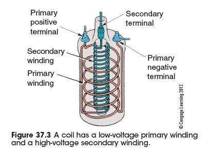
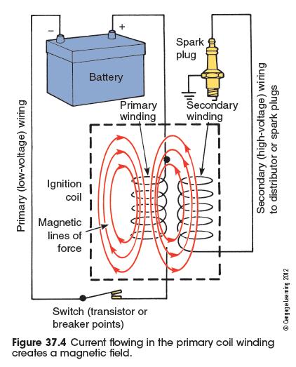
7 Ignition Coil Heart of the ignition system Has a low-voltage primary winding and highvoltage secondary winding Magnetic field Collapses when current flow is interrupted in primary winding Magnetic lines of force Cut across the secondary windings and create high voltage and low amperage
8
9
10 Saturation Ignition Coil (cont'd.) Coil is saturated when magnetic field finished its buildup inside coil Coil saturation time depends on amount of current in primary winding Dwell Length of time current flows in primary winding Determined by ignition control module Electronic ignition varies dwell time
11 Secondary Ignition Parts Secondary circuit Delivers high voltage from coil to spark plugs Distributor ignition (DI) system components Cam Distributor cap and rotor DI systems: electricity flows from coil to distributor cap and rotor Distributor rotates at one-half crankshaft speed Spark plug cables are inserted in the distributor cap following engine firing order
12 Spark Plugs Spark ignites compressed air-fuel mixture Length of threaded area called reach Heat range indicates how fast heat travels away from the center electrode Determined by how far ceramic insulator extends into combustion chamber Spark plugs have a tapered seat or flat seat with a gasket to seal against cylinder head There is controversy over long-life spark plugs Precious metals are used to prolong life
13 Spark Plugs (cont'd.) Resistor plugs and wires Resistance added to secondary ignition system with spark plugs or spark plug cables Resistor inside spark plug raises firing voltage required by the output coil Spark plug cable Resistor cables are very fragile Secondary wiring must be well insulated Leak in insulation will cause a spark to short to ground
14 Electronic Ignitions Trigger mechanism Controls current flow in primary coil winding Nonelectric ignition systems Used mechanical contact points Alternately energized and then opened primary ignition circuit Contact points require periodic replacement Experience wear to rubbing block that rides against the distributor cam
15 Electronic Ignition Operation Transistor triggers buildup and collapse of magnetic field Housed in an ignition module or in PCM Transistor Electronic switch or relay Power transistor: controlled by driver transistor Components: emitter, collector, and base Switches when a small amount of current is applied to its base
16
17 Electronic Ignition Variations Common electronic trigger: permanent magnet (PM) AC generator pickup Works like an alternator Pickup coil: wrapped around iron pole piece Trigger wheel: attached to distributor shaft Low magnetic reluctance Reluctor tooth moves away from pole piece and magnetic field becomes weaker Ignition module: alternating signal from PM generator is converted to DC
18 Hall-Effect Pickups Most popular electronic ignition triggering device Has a stationary sensor and rotating trigger wheel Signal is a rise in voltage followed by a drop Components: permanent magnet, Hall element, and cupped metal ring Creates a small analog voltage signal strengthened by an amplifier Converted to square wave by Schmidt trigger Generate rpm signals and are very accurate Used as a crankshaft position sensor
19 Magnetoresistive Sensors Create a square wave digital signal Includes two MR pickups phased a small distance from each other Creates its own five-volt reference signal Permanent magnet is sandwiched between two sideways magnetic reluctance pickups One pickup gets the signal sooner than the other Differential signal switches a Schmidt trigger
20 Optical Sensors A beam of light controls primary circuit Sensor shines beam on one side of slotted disc Disc interrupts the light: voltage stops Automotive engine use Called crank angle sensors Computer determines crankshaft position, cylinder identification, and rpm from openings
21 Ignition Modules Newer ignition modules functions Turn primary current on and off Limit current Vary dwell Current limiting system Has variable resistance within an ignition module Ignition module turns current flow off as soon as coil primary winding is saturated
22 Ignition is timed Ignition Timing So it occurs just before piston reaches top of compression stroke Ignition timing variation Computer determines best ignition timing setting Advanced or retarded in response to engine speed and load changes, altitude, and engine temperature Intake manifold vacuum senses engine load
23 Ignition Timing (cont'd.) Computer systems continuously adjust spark timing to optimize power and emissions Some functions were not possible with mechanical distributors Throttle position sensor determines throttle position MAP sensor determines intake manifold pressure Primary trigger interprets engine speed Coolant temperature sensor allows adjustments for changes in engine temperature
24 Detonation Sensor Controls maximum spark advance Piezoelectric crystal detects the frequency of spark knock PCM retards timing in steps until vibration stops Advances timing until knocking occurs Checks if outside air temperature is high to prevent detonation
25 Distributorless Ignition Advantages of EI Reduced cost and lower maintenance No rotor, distributor cap, or spark plug cables Crankshaft position sensor Determines engine speed and crankshaft position Camshaft position sensor Gives information for sequencing fuel injection system and coil firing
26 Distributorless Ignition (cont d.) Waste spark One coil for every two spark plugs Some engines have two spark plugs per cylinder One on the combustion chamber s intake side The other is on the exhaust side
27
ATASA 5 th. ATASA 5 TH Study Guide Chapter 27 Pages Ignition Systems 68 Points. Please Read the Summary
 ATASA 5 TH Study Guide Chapter 27 Pages 810 835 68 Points Please Read the Summary Before We Begin Keeping in mind the Career Cluster of Transportation, Distribution & Logistics Ask yourself: What careers
IGNITION SYSTEM COMPONENTS AND OPERATION
 69 IGNITION SYSTEM COMPONENTS AND OPERATION Figure 69-1 A point-type distributor from a hot rod being tested on a distributor machine. WARNING: The spark from an ignition coil is strong enough to cause
CHAPTER 6 IGNITION SYSTEM
 CHAPTER 6 CHAPTER 6 IGNITION SYSTEM CONTENTS PAGE Faraday s Law 02 The magneto System 04 Dynamo/Alternator System 06 Distributor 08 Electronic System 10 Spark Plugs 12 IGNITION SYSTEM Faraday s Law The
IGNITION SYSTEM 8D - 1 IGNITION SYSTEM TABLE OF CONTENTS
 LH IGNITION SYSTEM 8D - 1 IGNITION SYSTEM TABLE OF CONTENTS page AND IGNITION SYSTEM...1 SPARK PLUGS-PLATINUM....1 COIL ON PLUG...1 CRANKSHAFT POSITION SENSOR....2 CAMSHAFT POSITION SENSOR....3 KNOCK SENSOR....5
16.01 Theory Module INPUTS
 16.01 Theory Module INPUTS Crankshaft position sensor Camshaft position sensor Knock sensor (some engine types) Barometric pressure sensor Intake air temperature sensor Engine coolant temperature sensor
Sensors & Controls. Everything you wanted to know about gas engine ignition technology but were too afraid to ask.
 Everything you wanted to know about gas engine ignition technology but were too afraid to ask. Contents 1. Introducing Electronic Ignition 2. Inductive Ignition 3. Capacitor Discharge Ignition 4. CDI vs
AUTOMOTIVE ENGINEERING SECTION
 PURPOSE OF IGNITION SYSTEM The ignition system supplies high-voltage surges as high as 47,000 volts (in some electronic systems) to the spark plugs in the engine cylinders. These surges produce electric
IGNITION SYSTEM IGNITION SYSTEM
 IGNITION SYSTEM IGNITION SYSTEM opyright Gautam Malik 2007 IGNITION SYSTEM opyright Gautam Malik 2007 IGNITION FUNTION Produces 15000-30,000 volt spark across spark plug Distributes high voltage spark
Chrysler Electronic Ignition System
 1 of 11 1/6/2010 11:02 PM Chrysler Electronic Ignition System Classic Winnebago's Post by: DaveVA78Chieftain on August 13, 2009, 10:15 PM Components The Chrysler Electronic Ignition System consists of
Fiero Ignition Systems. January 20, 2018 Rock Chevrolet Northern Illinois Fiero Enthusiasts Presented by Art Hall and Ray Dyreson
 Fiero Ignition Systems January 20, 2018 Rock Chevrolet Northern Illinois Fiero Enthusiasts Presented by Art Hall and Ray Dyreson 1 The Stock Fiero has Two Types of Ignition Systems Distributor 4 cyl: 84,
The PCM is the on-board computer which receives input from various sensors and, with this information, controls various engine & emissions control
 The PCM is the on-board computer which receives input from various sensors and, with this information, controls various engine & emissions control actuators. The PCM has various memories within it. These
UNIT 4 IGNITION SYSTEMS
 UNIT 4 IGNITION SYSTEMS Ignition Systems Structure 4.1 Introduction Objectives 4.2 Ignition System Types 4.3 Comparison between Battery and Magneto Ignition System 4.4 Drawbacks (Disadvantages) of Conventional
Timing is everything with internal combustion engines By: Bernie Thompson
 Timing is everything with internal combustion engines By: Bernie Thompson As one goes through life, it is said that timing is everything. In the case of the internal combustion engine, this could not be
AUTOMOTIVE TECHNOLOGY Electricity and Electronics
 AUTOMOTIVE TECHNOLOGY Electricity and Electronics Al Santini Retired, College of DuPage Glen Ellyn, Illinois Jack Erjavec, Series Editor Professor Emeritus, Columbus State Community College Columbus, Ohio
SECTION 2.10 IGNITION SYSTEM DESCRIPTION CEC IGNITION MODULE SYSTEM MAGNETO IGNITION SYSTEM
 SECTION 2.10 SYSTEM DESCRIPTION CEC SYSTEM The Custom Engine Control (CEC) Ignition Module is located on the engine's left side (see Figure 2.10-1 and Figure 2.10-2). The CEC Ignition Module system consists
ASE 8 - Engine Performance. Module 8 Ignition Systems Triggering
 Module 8 Ignition Acknowledgements General Motors, the IAGMASEP Association Board of Directors, and Raytheon Professional Services, GM's training partner for GM's Service Technical College wish to thank
Ladies and Gentlemen... We Have Ignition!
 FEATURE Ladies and Gentlemen... We Have Ignition! The coordination of ignition, fuel delivery and basic engine function is required before internal combustion can take place. Here, we'll look at the ignition
Engine Systems. Basic Engine Operation. Firing Order. Four Stroke Cycle. Overhead Valves - OHV. Engine Design. AUMT Engine Systems 4/4/11
 Advanced Introduction Brake to Automotive Systems Diagnosis Service and Service Basic Engine Operation Engine Systems Donald Jones Brookhaven College The internal combustion process consists of: admitting
Motronic September 1998
 The Motronic 1.8 engine management system was introduced with the 1992 Volvo 960. The primary difference between this Motronic system and the previous generation of Volvo LH-Jetronic engine management
ASE 8 - Engine Performance. Module 9 Ignition Systems
 ASE 8 - Engine Module 9 Acknowledgements General Motors, the IAGMASEP Association Board of Directors, and Raytheon Professional Services, GM's training partner for GM's Service Technical College wish to
AUTOMOTIVE IGNITION SYSTEMS
 AUTOMOTIVE IGNITION SYSTEMS ABSTRACT This report describes the differences and similarities between a 1964 Mustang traditional ignition system and that of my 2014 Jeep. To help you understand the process
FUEL INJECTION SYSTEM - MULTI-POINT
 FUEL INJECTION SYSTEM - MULTI-POINT 1988 Jeep Cherokee 1988 Electronic Fuel Injection JEEP MULTI-POINT 4.0L Cherokee, Comanche, Wagoneer DESCRIPTION The Multi-Point Electronic Fuel Injection (EFI) system
Contents. Preface... xiii Introduction... xv. Chapter 1: The Systems Approach to Control and Instrumentation... 1
 Contents Preface... xiii Introduction... xv Chapter 1: The Systems Approach to Control and Instrumentation... 1 Chapter Overview...1 Concept of a System...2 Block Diagram Representation of a System...3
Ignition Why You Need A Spark
 Simply put, an ignition system activates a fuel-air mixture to create energy. The first ignition system to use an electric spark is thought to be Alessandro Volta s toy electric pistol, ca. 1780. We ve
2003 Nissan-Datsun Truck Frontier 4WD V6-3.3L (VG33E)
") 1 of 15 8/7/2016 2:34 PM 2003 Nissan-Datsun Truck Frontier 4WD V6-3.3L (VG33E) Vehicle» Engine, Cooling and Exhaust» Engine» Cylinder Head Assembly» Service and Repair» Removal and Installation 2 of 15
1 of 15 8/7/2016 2:34 PM 2003 Nissan-Datsun Truck Frontier 4WD V6-3.3L (VG33E) Vehicle» Engine, Cooling and Exhaust» Engine» Cylinder Head Assembly» Service and Repair» Removal and Installation 2 of 15
4.0L CEC SYSTEM Jeep Cherokee DESCRIPTION OPERATION FUEL CONTROL DATA SENSORS & SWITCHES
 4.0L CEC SYSTEM 1988 Jeep Cherokee 1988 COMPUTERIZED ENGINE Controls ENGINE CONTROL SYSTEM JEEP 4.0L MPFI 6-CYLINDER Cherokee, Comanche & Wagoneer DESCRIPTION The 4.0L engine control system controls engine
EM2007 Errata Student Manual 13 April 2008 Replace referenced paragraphs and homework questions with the following:
 EM2007 Errata Student Manual 13 April 2008 Replace referenced paragraphs and homework questions with the following: Paragraph 7 Internal combustion engines convert about one third of the fuel s energy
Chapter 5 Part B: Ignition system - transistorised type
 5B 1 Chapter 5 Part B: Ignition system - transistorised type Contents Coil - testing........................................... 9 Distributor - overhaul..................................... 7 Distributor
AUTOMOTIVE MAINTENANCE TECHNOLOGY SUBJECT: AUTOTRONIC 2 TITLE: BREAKER-TRIGGERED TRANSISTORISED IGNITION TI-B
 Breaker-triggered transistorized ignition TI-B The ignition distributor of the breaker- triggered transistorized ignition system (TI-B) is identical to the ignition distributor of the breaker-triggered
Engine Design Classifications
 Chapter 12 Engine Design Classifications Name: Date: Instructor: Score: Textbook pages 158-175 Objective: After studying this chapter, you will be able to describe and explain basic automotive engine designs
CPi. CoiL PACK IGNiTioN FOR AViATiON. For 4,6 and 8 cylinder 4 stroke applications. Please read the entire manual before beginning installation.
 1 CPi CoiL PACK IGNiTioN FOR AViATiON Coil pack (4 cylinder) Coil pack (6 cylinder) For 4,6 and 8 cylinder 4 stroke applications. Please read the entire manual before beginning installation. Software version
F - BASIC TESTING Article Text 1992 Dodge Colt For a a a a a Copyright 1998 Mitchell Repair Information Company, LLC Saturday, April 27, :48PM
 Article Text ARTICLE BEGINNING 1992 ENGINE PERFORMANCE Chrysler Motors/Mitsubishi Basic Diagnostic Procedures Chrysler Motors: Colt, Colt 200, Summit Mitsubishi: Mirage INTRODUCTION The following diagnostic
Truck and Transport IP Red Seal Practice Exam PRACTICE EXAM 4
 Truck and Transport IP Red Seal Practice Exam PRACTICE EXAM 4 1. Which of these sensors directly measures engine load? a. Manifold absolute pressure sensor. b. Coolant sensor (ECT). c. Vehicle speed sensor.
Electronics III Sensors
 Electronics III Sensors Matthew Whitten Brookhaven College Sensor Defined. A device that responds to a stimulus, such as heat, light, or pressure, and generates a signal that can be measured or interpreted.
MONO - MOTRONIC 0309 En
 02.1992 MONO - MOTRONIC 0309 En Published by: Robert Bosch GmbH Division KH After-Sales-Service Department for Training and Technology (KH/VSK) Please direct questions and comments concerning the contents
Kubota Engine Training: WG1605, spark ignited
 Kubota Engine Training: WG1605, spark ignited WG1605 Engine Training: System Overviews Mechanical Components Electronic Components and Sensors Operation Service Tool Fuel System Overview: Fuel System Overview:
1984 Jeep CJ7. IGNITION SYSTEM - SOLID STATE' 'Distributors & Ignition Systems MOTORCRAFT SOLID STATE IGNITION (SSI)
") TESTING SECONDARY CIRCUIT CHECK CAUTION: When checking secondary voltage, do not remove spark plug wires from spark plugs No. 3 on 4-cylinder, No. 1 or 5 on 6-cylinder and No. 3 or 4 on V8 Engines. 1.
TESTING SECONDARY CIRCUIT CHECK CAUTION: When checking secondary voltage, do not remove spark plug wires from spark plugs No. 3 on 4-cylinder, No. 1 or 5 on 6-cylinder and No. 3 or 4 on V8 Engines. 1.
DISTRIBUTORLESS IGNITION SYSTEM Installation and Adjustment Instructions
 DISTRIBUTORLESS IGNITION SYSTEM Installation and Adjustment Instructions 1.0 INTRODUCTION: Congratulations on your purchase of a Holley Distributorless Ignition System! Holley cannot and will not be responsible
Gen III HEMI Harness PN or
 Gen III HEMI Harness PN 558-106 or 558-107 This wiring harness interfaces a Holley EFI ECU to a Gen III HEMI engine. It is meant to be used in conjunction with an injector harness, a coil harness, and
Chapter 4 Ignition & Electrical Systems
 Chapter 4 Ignition & Electrical Systems Chapter 4 Section A Study Aid Questions Fill in the Blanks 1. Ignition systems can be divided into two classifications: systems or systems for reciprocating engines.
MULTIPORT FUEL SYSTEM (MFI) <2.4L ENGINE>
 <2.4L ENGINE>") 13B-1 GROUP 13B MULTIPORT FUEL SYSTEM (MFI) CONTENTS GENERAL DESCRIPTION 13B-2 CONTROL UNIT 13B-5 SENSOR 13B-7 ACTUATOR 13B-24 FUEL INJECTION CONTROL 13B-31 IGNITION TIMING AND CONTROL FOR
13B-1 GROUP 13B MULTIPORT FUEL SYSTEM (MFI) CONTENTS GENERAL DESCRIPTION 13B-2 CONTROL UNIT 13B-5 SENSOR 13B-7 ACTUATOR 13B-24 FUEL INJECTION CONTROL 13B-31 IGNITION TIMING AND CONTROL FOR
FUELMISER PRODUCT RANGE
 FUELMISER PRODUCT RANGE The broadest from world leading WE KNOW HOW IMPORTANT IT IS TO KNOW THAT OUR HIGH QUALITY PRODUCTS ARE MADE BY LEADING OEM & OES MANUFACTURERS. That s why Fuelmiser products are
1.0 Installation Wiring
 1.0 Installation Wiring DX Firebox is designed to be an electronic replacement for Pontiac & Ford buzz coils when operated on DC. Installation may be positive or negative ground. Simply observe the RED
Electronics III Sensors
 Electronics III Sensors Matthew Whitten Brookhaven College Sensor Defined. A device that responds to a stimulus, such as heat, light, or pressure, and generates a signal that can be measured or interpreted.
POLESTAR HS Management System
 POLESTAR HS Management System Installation Instructions This document contains the information needed to install and adjust the POLESTAR HS Engine Management System. It assumes that the system already
MSD Pro-Billet Distributor Buick 400, 430, PN 8552 Buick Nailhead - PN 8524
 MSD Pro-Billet Distributor Buick 400, 430, 455 - PN 8552 Buick Nailhead - PN 8524 Important: Read these instructions before attempting the installation. Parts Included: 1 - Pro-Billet Distributor 1 - Rotor,
E - THEORY/OPERATION - TURBO
 E - THEORY/OPERATION - TURBO 1995 Volvo 850 1995 ENGINE PERFORMANCE Volvo - Theory & Operation 850 - Turbo INTRODUCTION This article covers basic description and operation of engine performance-related
Ignition System Inspection and Component Testing (Distributor Vehicle)
") JOB SHEET 92 Ignition System Inspection and Component Testing (Distributor Vehicle) Name:-------------- Station: Date: NATEF Correlation This Job Sheet addresses the following NATEF task(s): 8.C.2 8.C.3
JOB SHEET 92 Ignition System Inspection and Component Testing (Distributor Vehicle) Name:-------------- Station: Date: NATEF Correlation This Job Sheet addresses the following NATEF task(s): 8.C.2 8.C.3
MULTIPORT FUEL SYSTEM (MFI)
") 13A-1 GROUP 13A CONTENTS GENERAL INFORMATION...13A-2 CONTROL UNIT...13A-7 SENSOR...13A-9 ACTUATOR...13A-26 FUEL INJECTION CONTROL...13A-31 IGNITION TIMING AND CONTROL FOR CURRENT CARRYING TIME...13A-36
13A-1 GROUP 13A CONTENTS GENERAL INFORMATION...13A-2 CONTROL UNIT...13A-7 SENSOR...13A-9 ACTUATOR...13A-26 FUEL INJECTION CONTROL...13A-31 IGNITION TIMING AND CONTROL FOR CURRENT CARRYING TIME...13A-36
3. At sea level, the atmosphere exerts psi of pressure on everything.
 41 Chapter Gasoline Injection Fundamentals Name Instructor Date Score Objective: After studying this chapter, you will be able to explain the construction, operation, and classifications of modern gasoline
IGNITION COIL - 2.4L SPARK PLUG
 TJ IGNITION CONTROL 8I - 13 IGNITION COIL - 2.4L DESCRIPTION - 2.4L The coil assembly consists of 2 different coils molded together. The assembly is mounted to the top of the engine (Fig. 21). REMOVAL
04. Ignition and Exhaust system
 New Polytechnic Kolhapur Page 1 of 10 04. Ignition and Exhaust system 4.1 Introduction to Ignition System 4 Marks Requirements of ignition system. Magneto and Battery Ignition systems (Working only). Firing
Lab #5 4-Cylinder Single Overhead Cam Engine Dissection
 Engr 3 Mission College Faculty: Kate Disney TA: Andrew Dina Lab #5 4-Cylinder Single Overhead Cam Engine Dissection Equipment: 4-Cylinder Mazda 16 Valve SOHC 92 (Manual Transmission) Ratchet with 2 and
Installation Guide for the Electronic Ignition Distributor
 Installation Guide for the Electronic Ignition Distributor Remanufactured By East Coast Roadster East Coast Roadster: Ignition systems and accessories for Datsun Roadster fanatics! PLEASE, Call with any
ATASA 5 th. ATASA 5 TH Study Guide Chapter 28 Pages Ignition Diagnosis & Service 62 Points. Please Read the Summary
 ATASA 5 TH Study Guide Chapter 28 Pages 836 873 62 Points Please Read the Summary Before We Begin Keeping in mind the Career Cluster of Transportation, Distribution & Logistics Ask yourself: What TDL careers
IGNITION SYSTEM 8D - 1 IGNITION SYSTEM CONTENTS
 ZJ IGNITION SYSTEM 8D - 1 IGNITION SYSTEM CONTENTS page GENERAL INFORMATION INTRODUCTION... 2 DESCRIPTION AND OPERATION AUTOMATIC SHUTDOWN (ASD) RELAY... 3 CAMSHAFT POSITION SENSOR... 4 CRANKSHAFT POSITION
Example of Single Pole Double Throw (SPDT) Switch in Circuit:
 Switch in Circuit:") Subject Code: 17617 Model Answer Page No: 1/8 Important Instructions to examiners: 1) The answers should be examined by key words and not as word-to-word as given in the model answer scheme. ) The model
Subject Code: 17617 Model Answer Page No: 1/8 Important Instructions to examiners: 1) The answers should be examined by key words and not as word-to-word as given in the model answer scheme. ) The model
GROUP CONTENTS CHARGING SYSTEM IGNITION SYSTEM SPECIAL TOOL GENERAL DESCRIPTION
 16-1 GROUP 16 CONTENTS CHARGING SYSTEM 16-3 GENERAL DESCRIPTION 16-3 SPECIAL TOOL 16-4 CHARGING SYSTEM DIAGNOSIS 16-4 ON-VEHICLE SERVICE 16-6 GENERATOR OUTPUT LINE VOLTAGE DROP TEST 16-6 OUTPUT CURRENT
SECTION C Engine 5.4L (4V)
") 303-01C-i Engine 5.4L (4V) 303-01C-i SECTION 303-01C Engine 5.4L (4V) CONTENTS PAGE SPECIFICATIONS... 303-01C-2 303-01C-2 Engine 5.4L (4V) 303-01C-2 SPECIFICATIONS Material Motorcraft Metal Surface Prep
303-01C-i Engine 5.4L (4V) 303-01C-i SECTION 303-01C Engine 5.4L (4V) CONTENTS PAGE SPECIFICATIONS... 303-01C-2 303-01C-2 Engine 5.4L (4V) 303-01C-2 SPECIFICATIONS Material Motorcraft Metal Surface Prep
FUNDAMENTAL OF AUTOMOBILE SYSTEMS
 Prof. Kunalsinh Mechanical Engineering Dept. FUNDAMENTAL OF AUTOMOBILE SYSTEMS Prof. Kunalsinh kathia [MECHANICAL DEPT.] UNIT-2 [ENGINES] PART-1 Prof. Kunalsinh kathia [MECHANICAL DEPT.] Internal combustion
Fuel Metering System Component Description
 1999 Chevrolet/Geo Tahoe - 4WD Fuel Metering System Component Description Purpose The function of the fuel metering system is to deliver the correct amount of fuel to the engine under all operating conditions.
CH. 48 ENGINE MECHANICAL PROBLEMS TEST
 TERRY FOX AUTOMOTIVE CH. 48 ENGINE MECHANICAL PROBLEMS TEST WHEN YOU ARE DONE THIS TEST GUESS WHAT YOU THINK YOU WILL RECEIVE FOR A MARK BELOW. IF YOU ARE WITHIN 2 MARKS YOU WILL RECEIVE 2 BONUS MARKS.
VALVE TIMING DIAGRAM FOR SI ENGINE VALVE TIMING DIAGRAM FOR CI ENGINE
 VALVE TIMING DIAGRAM FOR SI ENGINE VALVE TIMING DIAGRAM FOR CI ENGINE Page 1 of 13 EFFECT OF VALVE TIMING DIAGRAM ON VOLUMETRIC EFFICIENCY: Qu. 1:Why Inlet valve is closed after the Bottom Dead Centre
Fig.11 Powertrain Control Module (PCM)
") 2003 Dodge or Ram Truck Caravan V6-3.3L VIN R Vehicle > Powertrain Management > Relays and Modules - Powertrain Management > Relays and Modules - Computers and Control Systems > Engine Control Module >
2003 Dodge or Ram Truck Caravan V6-3.3L VIN R Vehicle > Powertrain Management > Relays and Modules - Powertrain Management > Relays and Modules - Computers and Control Systems > Engine Control Module >
5.7L ENGINE PARTS BOOK. Not for. Reproduction
 5.7L ENGINE PARTS BOOK Engine Model: Engine Family: PSI, Industrial Engine Spec N.: 39004120-39004248 Parts Book Revision: December, 2015 TABLE OF CONTENTS SECTION PAGE CYLINDER BLOCK... 3-5 CYLINDER HEAD...
Bosch Motronic 2.5 Copyright Equiptech
 1 Motronic 2.5 operation Motronic 2.5 is an enhancement of the Motronic 4.1 EMS fitted to earlier Vauxhall and Opel vehicles. It was first fitted in the 1990 model year (late 1989) and is a fully integrated
LONG BEACH CITY COLLEGE AUTO MECHANICS 233 AUTOMOTIVE ELECTRICAL & FUEL SYSTEMS SPRING 2005
 LONG BEACH CITY COLLEGE AUTO MECHANICS 233 AUTOMOTIVE ELECTRICAL & FUEL SYSTEMS SPRING 2005 SUBJECT MATTER AREA Automotive Technology COURSE NUMBER AMECH 233 SECTION NUMBER 31377 ROOM # MM128A/MM130 COURSE
MSD Pro-Billet Digital E-Curve Distributor PN U.S. Patent
 MSD Pro-Billet Digital E-Curve Distributor PN 8394 - U.S. Patent 6820602 ONLINE PRODUCT REGISTRATION: Register your MSD product online. Registering your product will help if there is ever a warranty issue
Spark Plug Valve Spring Mixture In. Cylinder Head. Intake Valve. Cooling Water. Piston. Crankcase
 Simply put, an ignition system activates a fuel-air mixture to create energy. The first ignition system to use an electric spark is thought to be Alessandro Volta s toy electric pistol, ca. 1780. We ve
Error codes Diagnostic plug Read-out Reset Signal Error codes
 Error codes Diagnostic plug Diagnostic plug: 1 = Datalink LED tester (FEN) 3 = activation error codes (TEN) 4 = positive battery terminal (+B) 5 = ground Read-out -Connect LED tester to positive battery
ENGINE ELECTRICAL Click on the applicable bookmark to selected the required model year
 ENGINE ELECTRICAL 16-1 ENGINE ELECTRICAL CONTENTS CHARGING SYSTEM................ 2 GENERAL INFORMATION................ 2 SERVICE SPECIFICATIONS.............. 3 SPECIAL TOOL......................... 3
INSTALLATION INSTRUCTIONS
 INSTALLATION INSTRUCTIONS 2009 CORVETTE LS - 9 INSTALLATION INSTRUCTIONS FOR LS 9 The following instructions are intended as an aid to assist in harness installation. More in depth information can be obtained
The following flow charts and schematics are courtesy of General Motors Corp. Chart No. No Malfunction Indicator Lamp (MIL)
") Page 1 of 13 DIAGNOSTIC CHARTS NOTE: The following flow charts and schematics are courtesy of General Motors Corp. DIAGNOSTIC CHARTS Malfunction (1) Chart No. No Malfunction Indicator Lamp (MIL) (2) A1-1
Page 1 of 13 DIAGNOSTIC CHARTS NOTE: The following flow charts and schematics are courtesy of General Motors Corp. DIAGNOSTIC CHARTS Malfunction (1) Chart No. No Malfunction Indicator Lamp (MIL) (2) A1-1
Engine Cylinder Head Installation
 Engine Cylinder Head Installation Important: Install the cylinder head without the camshafts. 1. Install the engine cylinder head to the engine block. 2. Install the AIR pump bolt and fir tree fastener
Unit AE01K Knowledge of Locating and Correcting Simple Electrical Faults in the Automotive Workplace
 Assessment Requirements Unit AE01K Knowledge of Locating and Correcting Simple Electrical Faults in the Automotive Workplace Content: Basic electrical principles a. Explain the direction of current flow
Delomatic 400 (DM 400) based Gas Engine and Combined Heat and Power (CHP) Control and Management System
 based Gas Engine and Combined Heat and Power (CHP) Control and Management System") Table of contents 1. WARNINGS AND LEGAL INFORMATION... 3 3.5 LEGAL INFORMATION AND RESPONSIBILITY... 3 3.6 ELECTROSTATIC DISCHARGE AWARENESS... 3 3.7 SAFETY ISSUES... DELOMATIC 400 GAS 3 3.8 DISCLAIMER...
Table of contents 1. WARNINGS AND LEGAL INFORMATION... 3 3.5 LEGAL INFORMATION AND RESPONSIBILITY... 3 3.6 ELECTROSTATIC DISCHARGE AWARENESS... 3 3.7 SAFETY ISSUES... DELOMATIC 400 GAS 3 3.8 DISCLAIMER...
Contents. DX Ignition Page 2
 Contents 1.0 Intent 2.0 Specifications 3.0 Installation 4.0 Operation Precautions 5.0 Repair 6.0 Parts List 7.0 Glossary of Terms 8.0 Contact Information DX Ignition Page 2 1.0 Intent The purpose of this
Bi-Fuel Conversion for High Speed Diesel Engins
 Bi-Fuel Conversion for High Speed Diesel Engins Introduction The bi-fuel system modifies standard heavy-duty diesel engines to operate on diesel and gas simultaneously. The gas is used as main fuel and
Simple Carburettor Fuel System for a Piston Engine. And how it works
 Simple Carburettor Fuel System for a Piston Engine And how it works Inlet Exhaust Tank PISTON ENGINE Carburettor Fuel System Filler Cap COCKPIT FUEL GAUGE E FUEL 1/2 F Filler Neck Tank Cavity FUEL LEVEL
4. Sensors and Switches
 FUEL INJECTION (FUEL SYSTEM) SENSORS AND SWITCHES 4. Sensors and Switches A: FRONT OXYGEN (A/F) SENSOR The front oxygen sensor uses zirconium oxide (ZrO 2 ) which is a solid electrolyte, at portions exposed
EMISSION CONTROL (AUX. EMISSION CONTROL DEVICES) H6DO
 H6DO") EMISSION CONTROL (AUX. EMISSION CONTROL DEVICES) H6DO SYSTEM OVERVIEW 1. System Overview There are three emission control systems, which are as follows: Crankcase emission control system Exhaust emission
EMISSION CONTROL (AUX. EMISSION CONTROL DEVICES) H6DO SYSTEM OVERVIEW 1. System Overview There are three emission control systems, which are as follows: Crankcase emission control system Exhaust emission
for EVO/2G DSM crank angle sensor Version 1.4
 for EVO/2G DSM crank angle sensor Version 1.4 Thank you for purchasing a triggerdisc! Your package should include a disc and two small shims. These instructions will cover the installation of the disc
MSD Pro-Billet Digital E-Curve Distributor PN U.S. Patent
 MSD Pro-Billet Digital E-Curve Distributor PN 8394 - U.S. Patent 6820602 Important: Read these Instructions before attempting the installation. Parts Included: 1 - Digital E-Curve Distributor 1 - Rotor,
STREET/RACE DISTRIBUTOR
 Installation Instructions for STREET/RACE DISTRIBUTOR CAUTION: READ INSTRUCTIONS CAREFULLY BEFORE STARTING INSTALLATION INTRODUCTION The Crane Cams street/race distributor is a high precision system intended
Disconnect the breather tube from the air cleaner outlet duct.
 Disconnect the breather tube from the air cleaner outlet duct. Disconnect the IAT sensor harness connector. Remove the air cleaner outlet duct retaining wingnut. Separate the air cleaner outlet duct from
F - BASIC TESTING Infiniti G20 INTRODUCTION PRELIMINARY INSPECTION & ADJUSTMENTS VISUAL INSPECTION MECHANICAL INSPECTION
 F - BASIC TESTING 1992 Infiniti G20 1992 ENGINE PERFORMANCE Infiniti Basic Diagnostic Procedures G20, M30, Q45 INTRODUCTION The following diagnostic steps will help prevent overlooking a simple problem.
2014 Hyundai Veloster ENGINE Ignition System - Veloster Turbo. Ignition System - Veloster Turbo
 DESCRIPTION AND OPERATION DESCRIPTION 2013-14 ENGINE Ignition System - Veloster Turbo Ignition timing is controlled by the electronic control ignition timing system. The standard reference ignition timing
Variable Valve Timing
 Service. Self-study programme 246 Variable Valve Timing with fluted variator Design and Function The demands on combustion engines continue to grow. On one hand, customers want more power and torque, while
MULTIPOINT FUEL INJECTION (MPI) <4G63-Non-Turbo>
 <4G63-Non-Turbo>") 13A-1 GROUP 13A MULTIPOINT FUEL INJECTI (MPI) CTENTS GENERAL INFORMATI........ 13A-2 FUEL INJECTI CTROL...... 13A-6 IDLE SPEED CTROL (ISC)..... 13A-7 IGNITI TIMING AND DISTRIBUTI CTROL........
13A-1 GROUP 13A MULTIPOINT FUEL INJECTI (MPI) CTENTS GENERAL INFORMATI........ 13A-2 FUEL INJECTI CTROL...... 13A-6 IDLE SPEED CTROL (ISC)..... 13A-7 IGNITI TIMING AND DISTRIBUTI CTROL........
Megasquirt EX, Installation Instructions document revision 1.4 (Includes also the version equipped with wasted-spark ignition)
") Megasquirt EX, Installation Instructions document revision 1.4 (Includes also the version equipped with wasted-spark ignition) General Megasquirt EX is a programmable engine control system, based on Megasquirt
Megasquirt EX, Installation Instructions document revision 1.4 (Includes also the version equipped with wasted-spark ignition) General Megasquirt EX is a programmable engine control system, based on Megasquirt
Current Content Edition 55
 Current Content Edition 55 Fundamentals Electrics Essential Electrical Skills Introduction to Electrics 166909 Fundamentals Electrics Essential Electrical Skills Voltage, Current and Resistance 147570
MSD Pro-Billet Ready-to-Run Chevrolet V8 Distributor, PN 8360 Chevrolet 348, 409 Distributor, PN 8393
 MSD Pro-Billet Ready-to-Run Chevrolet V8 Distributor, PN 8360 Chevrolet 348, 409 Distributor, PN 8393 ONLINE PRODUCT REGISTRATION: Register your MSD product online and you ll be entered in our monthly
MULTIPOINT FUEL INJECTION (MPI) <4G63-Turbo>
 <4G63-Turbo>") 13B-1 GROUP 13B MULTIPOINT FUEL INJECTI (MPI) CTENTS GENERAL INFORMATI........ 13B-2 SENSOR....................... 13B-8 THROTTLE VALVE OPENING ANGLE CTROL.............. 13B-9 FUEL INJECTI
13B-1 GROUP 13B MULTIPOINT FUEL INJECTI (MPI) CTENTS GENERAL INFORMATI........ 13B-2 SENSOR....................... 13B-8 THROTTLE VALVE OPENING ANGLE CTROL.............. 13B-9 FUEL INJECTI
EMISSION CONTROL (AUX. EMISSION CONTROL DEVICES) H4SO
 H4SO") EMISSION CONTROL (AUX. EMISSION CONTROL DEVICES) H4SO SYSTEM OVERVIEW 1. System Overview There are three emission control systems, which are as follows: Crankcase emission control system Exhaust emission
EMISSION CONTROL (AUX. EMISSION CONTROL DEVICES) H4SO SYSTEM OVERVIEW 1. System Overview There are three emission control systems, which are as follows: Crankcase emission control system Exhaust emission
Setup Tabs. Basic Setup: Advanced Setup:
 Setup Tabs Basic Setup: Password This option sets a password that MUST be entered to re-enter the system. Note: ProEFI can NOT get you into the calibration if you lose this password. You will have to reflash
3406E Truck Engine 5EK01821-UP(SEBP ) - Document Structure. Media Number -RENR Publication Date -01/02/2008 Date Updated -07/02/2008
 - Document Structure. Media Number -RENR Publication Date -01/02/2008 Date Updated -07/02/2008") Page 1 of 11 Shutdown SIS Previous Screen Product: TRUCK ENGINE Model: 3406E TRUCK ENGINE 5EK Configuration: 3406E Truck Engine 5EK01821-UP Systems Operation 3406E Truck Engine Media Number -RENR1273-07
Page 1 of 11 Shutdown SIS Previous Screen Product: TRUCK ENGINE Model: 3406E TRUCK ENGINE 5EK Configuration: 3406E Truck Engine 5EK01821-UP Systems Operation 3406E Truck Engine Media Number -RENR1273-07
2012 Honda Crosstour EX ENGINE Cylinder Head - (4-CYL)
") Fig. 4: Identifying Cylinder Head Components Location (3 Of 3) ENGINE COMPRESSION INSPECTION NOTE: After this inspection, you must reset the PCM. Otherwise, the PCM will continue to stop the fuel injectors
Fig. 4: Identifying Cylinder Head Components Location (3 Of 3) ENGINE COMPRESSION INSPECTION NOTE: After this inspection, you must reset the PCM. Otherwise, the PCM will continue to stop the fuel injectors
Chapter 5 Part B: Ignition system
 5B 1 Chapter 5 Part B: Ignition system Contents Distributor - removal and refitting.............................4 Ignition HT coil(s) - removal, testing and refitting.................3 Ignition system
DTC P0351, P0352, P0353, P0354, P0355, P0356, P0357, or P0358
 DTC Descriptor DTC P0351 Ignition coil 1 control circuit DTC P0352 Ignition coil 2 control circuit DTC P0353 Ignition coil 3 control circuit DTC P0354 Ignition coil 4 control circuit DTC P0355 Ignition
EMISSION CONTROL (AUX. EMISSION CONTROL DEVICES) H4DOTC
 H4DOTC") EMISSION CONTROL (AUX. EMISSION CONTROL DEVICES) H4DOTC SYSTEM OVERVIEW 1. System Overview There are three emission control systems, which are as follows: Crankcase emission control system Exhaust emission
EMISSION CONTROL (AUX. EMISSION CONTROL DEVICES) H4DOTC SYSTEM OVERVIEW 1. System Overview There are three emission control systems, which are as follows: Crankcase emission control system Exhaust emission