Automotive Parts. Charging & Starting Systems
|
|
|
- Claud Wilkinson
- 5 years ago
- Views:
Transcription


1 Automotive Parts Charging & Starting Systems
2 Charging Systems Output voltage kept to about 2 volts higher than battery voltage Controlled by varying current into rotor field winding (voltage regulator or PCM) No permanent magnets inside of the alternator Battery Testing with Midtronics Charging Output & Full Field Testing Carbon Pile Rheostat Identify Maximum Output on the Alternator Case
3
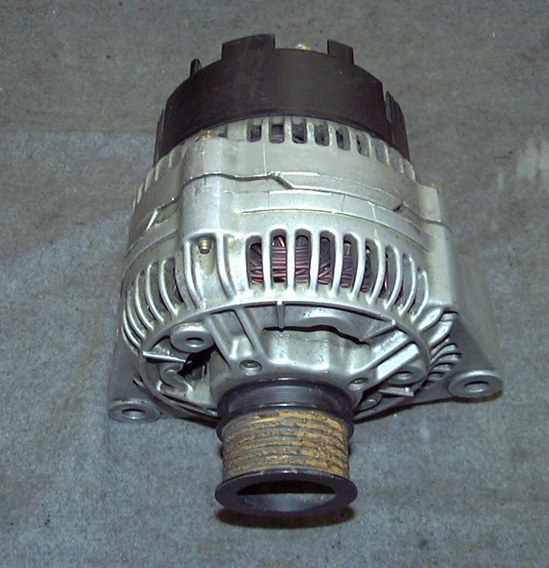
4 Alternator

5 Rotor with Field Coil Check rotor for opens, short coils, & shorts to the shaft Copper Slip Rings Rotor rotating magnetic field Check stator for opens, short coils, & shorts to the soft iron armature Stator stationary coils of wire Wye wound has 4 connections Delta wound has 3 connections

6 Diode Trio.4 to.7 VD in one direction OL in the other direction OL both ways = open 0.0 both ways = shorted

7 Full Fielding Tab Carbon Brush Brush Holders Internal Voltage Regulators
8 Rectifier Bridges change AC to DC before it leaves the alternator

9 B + Output side Ground side Test 6 diodes from copper tab to heat sink, Reverse leads to verify diode integrity

10 Charging System External Voltage Regulator Apply 12 volts to Field Terminal to full field the alternator
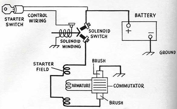
11 Starting (Cranking) Systems Cranks engine with a 10:1 to 15:1 reduction between starter drive pinion & ring gear Typical current draw is about 200 amps No click = no solenoid operation (check pull in coil) Click, but no crank = motor issue open windings Voltage Drop Test both B + and B cables (.2 maximum)
12

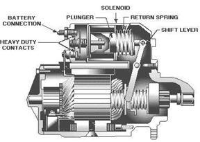
13 Starter Motor with solenoid mounted on it

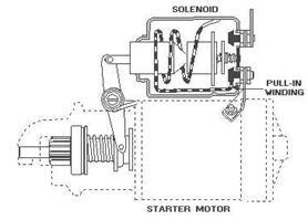
14 Movable Pole Shoe Starter Motor (solenoid mounted remotely)
15
16

17 Pinion Gear Starter Drive Fork Starter Drive with Overrunning Clutch Hold in & Pull in Windings Starter Mounted Solenoid

18 Pinion Gear Fork goes here Starter Drive Starter Shim gets placed between drive end housing & engine block

19 Remotely Mounted Starter Solenoids Used with movable pole shoe starter drives B B+ Apply 12 volts here to by pass the ignition switch

20 Solenoids Plungers

21 Automotive Parts Electrical & Accessory Systems
22 Electrical & Accessory Arguably one of the most intricate vehicle systems to trouble shoot Electrical Understanding is a Necessity! Even the dome light circuit is challenging now

23 Turn Signal &/or Hazard Flashers

24 Fusible Links with heat resistant Hypalon coating

25 Weather pack connector Fusible Links are 2 to 4 gauge sizes smaller than the regular circuit wiring

26 Ignition Switch. Located low on the steering column Operated by twisting the key Ignition Key & Lock Cylinder

27 Headlight Switch with dash light dimmer rheostat Has a push button to release the knob Ignition Switch Mechanism Located on Lower Steering Column

28 Brake Switch & Cruise Cancel Switch BPP or BOO Located on Brake Pedal Bracket

29 Air Temperature Sensors Ambient Evaporator Intake Air In evaporator housing In front of radiator Inlet air stream Cabin Air Temperature sensors found in automatic climate control HVAC

30 Low Brake Fluid Sensors Located on Master Cylinder

31 Blower Motor Resistors: drop the voltage to the blower motor to get a variety of speeds can be open on just one speed Solid State Solid State Coil Types

32 Battery Temperature Sensor Chrysler Located in the Bottom of the Battery Tray

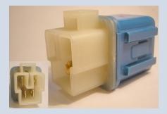
33 Solid State Flashers NOTE: Closely Resemble a Relay, but the number and the arrangement of the prongs differs Regular Flasher Turn Signal, Hazard, or Combo Blinks Faster with a Burnt Out Bulb

34 Brake Pedal Position Sensors Also used for brake light switch & cruise control cancel switch 1 Time Use BPP & BOO

35 Low Coolant Sensor Low Brake Fluid Sensor Float type Reed Switch type is also in use

36 Electronic Flasher built right on to the Hazard Switch Note: found on some versions of S.E.T. boards Regular Flashers Look very different than a round, European relay

37 Electric Seat Heater Switch & Harness Almost any switch is a good component to bug on a vehicle
38 Door Buzzer or Chime Many door ajar and dome light switches are now a part of the door latch mechanisms Door Jamb Switches

39 Wiring Harnesses can be tricky to trouble shoot Fuse hidden in the harness SIR/SRS wiring has yellow connectors High Voltage DC Hybrid power systems wiring is in a bright orange loom
 I Can be shorted to")
 I might also be diode equipped (.4 to.")
40 Test Voltage Available to me I am a Wiring Harness. How can I fail thee? Let me count the ways: I Can be open (inoperative) I Can be shorted to ground (fuse blow) I Can be shorted to power (always on) I Can have high resistance (voltage drop) I might also be diode equipped (.4 to.7 VD)

41 Diagnostic Link Connectors (DLC) OBD I & OBD II GM Chrysler Ford Toyota Global OBD II 1996 to present
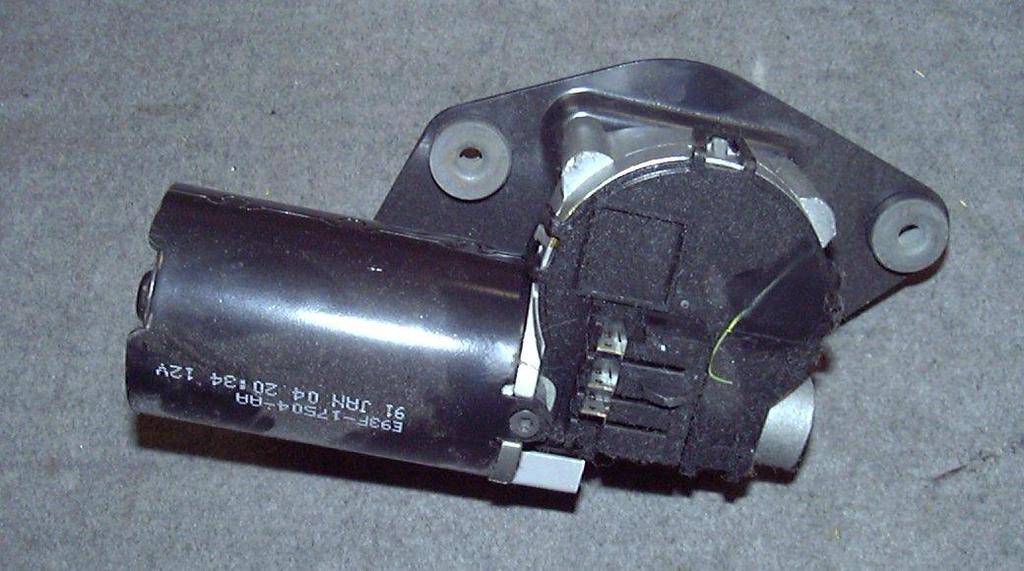
42 Windshield Wiper Motor Windshield Washer Pump Motors

43 Anti theft hood switch Key Fob Immobilizer Module with wrong key will cause a no start or a starts & stops Door Lock or Deck Lid Actuator or Motor
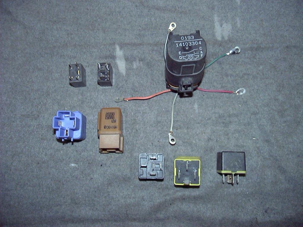
44 Relays
45 Relay coil typically has ohms OL = inoperative (no click) Insulated Contacts = click, but no conduct Jammed Contacts = good coil, but no click

46 Fuses of All Types Maxi Pal ATO Cartridge Fusible Links Glass Fuse Puller Missing Fuse Puller = Demerit
47 Circuit Breakers a forced open cb may read a few heater ohms

48 Diodes! Some resemble fuses, but note the prong positions Alternator Button Diode Often used as clamping diodes in large coil circuits

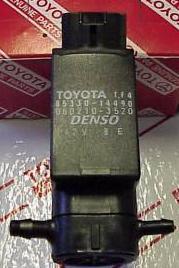
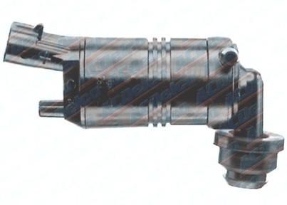
49 Windshield Washer Pump Motor


50 Weather Pack Connector Rocker Switch for a Window Know how to release wires from harness connectors

51 Hood &/or Deck Lid Light Switches Similar to those used in Glove Boxes Contain a mercury filled capsule that conducts only when the angle is correct

52 Multi Function Switch Snaps or screws into the steering column Lights Signals Wipers Cruise Popular competition bug: Wiring to and from Connectors at the MF Switch One tab that controls one small aspect of the switch

53 Bulbs & Sockets Cheap & easy open or short circuits! Headlamp Fog Lamp

54 Floor mounted Dimmer Switch Door Jamb Switch Very Old For Dome Light Operation

55 Windshield Washer Pump Motors Some vehicles have both a front & a rear washer pump motor

56 Hood & Deck Lid Light Switches

57 Horn Pad Switch grounds the relay coil to energize the horns

58 Seat Belt Switch Causes SIR codes, and keeps the warning chime on

59 SPOUT (Spark Output) Connectors Remove to put a Distributor Ignition Ford into base timing mode

60 Multi Function Switch Easily accessible through the steering column cover

61 Insulated ground = inoperative B B + Horn always relayed & fused
62
63
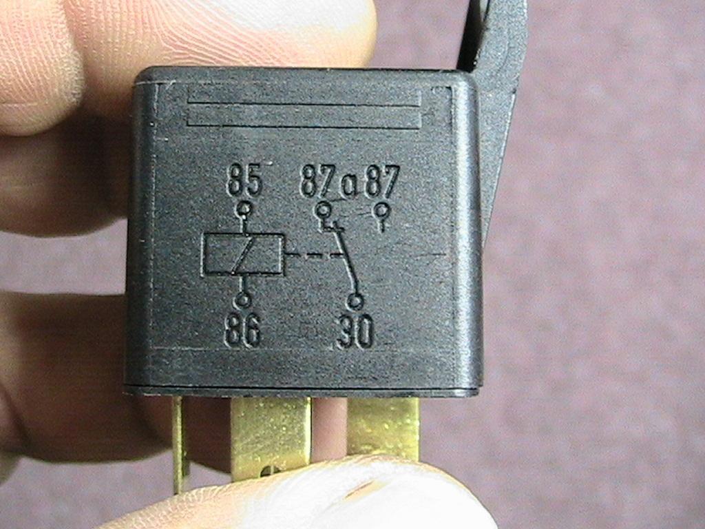
 87 = switched")
 A = switched")
64 85 to 85 = coil 30 = B+ 87a = NC (obedience check) 87 = switched output D to F = coil E = B+ C = NC (obedience check) A = switched output


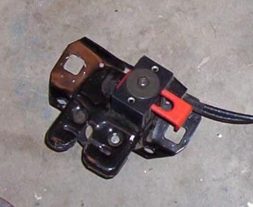
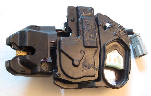
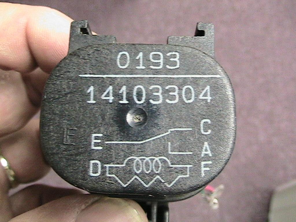
65 Door Latch & Trunk Latch

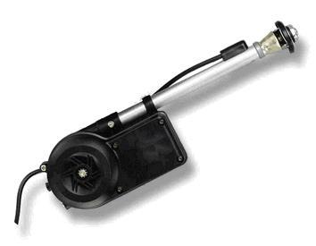
66 Electric Antenna Motor

67 Power Antenna Motor


68 Electric Window Cable Motor


69 Electric Window Regulator Motor


70 Electric Window Regulator Motor

71 Pulse Width Modulated Blower Motor
Starting Systems & Traction Motor Systems. ATASA 5 th. ATASA 5 TH Study Guide Chapter 18 Pages Starting & Traction Motor Systems 62 Points
 ATASA 5 TH Study Guide Chapter 18 Pages 537 570 Starting & Traction Motor Systems 62 Points Please Read The Summary 1. Electric are used to start the engine & in hybrids are used to move the vehicle. Motors
STARTING SYSTEMS 8B - 1 STARTING SYSTEMS CONTENTS
 TJ STARTING SYSTEMS 8B - 1 STARTING SYSTEMS CONTENTS page DESCRIPTION AND OPERATION STARTER MOTOR... 2 STARTER RELAY... 3 STARTING SYSTEM... 1 DIAGNOSIS AND TESTING STARTER MOTOR... 8 STARTER MOTOR NOISE
2001 Cougar Workshop Manual
 Page 1 of 7 SECTION 303-06: Starting System 2001 Cougar Workshop Manual DIAGNOSIS AND TESTING Procedure revision date: 09/14/2001 Starting System Refer to Wiring Diagrams Section 303-06 for schematic and
ELECTRICAL COMPONENT LOCATOR
 ELECTRICAL COMPONENT LOCATOR 1988 Toyota Celica 1988 TOYOTA Celica Electrical Components ---------------------------------------------------------------------- BUZZERS, RELAYS & TIMERS ----------------------------------------------------------------------
Fuse and Relay Information
 11-1 Fuse and Relay Information Battery Junction Box (BJB) (14A003) PCM power diode Air suspension compressor Front fog lamp cutoff Police power Traction control indicator A/C clutch Fuel pump C1300 C1008
Charging Systems. ATASA 5 th. ATASA 5 TH Study Guide Chapter 19 Pages Charging Systems 42 Points. Please Read The Summary
 ATASA 5 TH Study Guide Chapter 19 Pages 571 595 42 Points Please Read The Summary 1. The primary purpose of the charging system is to the battery with a constant and relatively low charge after it has
INSTRUCTIONS. 20 Circuit Wiring Kit Instructions October 2009, Speedway Motors, Inc.
 1 MAIN FUSE PANEL The main fuse panel harness s designed to be mounted under the dash a the firewall in an area close to the steering column. The enclosed representation of the main dash harness shows
jegs.com
 Contents Wiring Harness w/ Fuse Panel Installation Instructions Turn Signal Plug w/ Terminals 2 Headlight Plugs 3/4 Grommet 10 ¼ Terminals 4 Ring Terminals 10 Wire Ties Fusible Link 2 Screws & Nuts 2 Plastic
Battery Operation. Battery Construction. Battery State Of Charge. Battery Load Test. Battery Rating Systems 2/14/12
 Battery Operation Batteries, Charging and Donald Jones Brookhaven College Batteries convert chemical energy into electrical energy During discharge the battery s plate composition is changed During charging
G ELECTRICAL WIRING ROUTING
 G ELECTRICAL WIRING ROUTING Position of Parts in Engine Compartment A 1 A/C Condenser Fan Motor A 2 A/C Magnetic Clutch and Lock Sensor A 3 A/C Triple Pressure SW (A/C Dual and Signal Pressure SW) A 4
INSTRUMENT PANEL AND GAUGES INSTRUMENT PANEL AND GAUGES XJ
 J INSTRUMENT PANEL AND GAUGES 8E - 1 INSTRUMENT PANEL AND GAUGES GROUP INDEX INSTRUMENT PANEL AND GAUGES XJ... 1 INSTRUMENT PANEL AND GAUGES YJ... 24 INSTRUMENT PANEL AND GAUGES XJ CONTENTS page DIAGNOSIS...
G ELECTRICAL WIRING ROUTING [1MZ-FE] Position of Parts in Engine Compartment
![G ELECTRICAL WIRING ROUTING [1MZ-FE] Position of Parts in Engine Compartment](/thumbs/87/97394184.jpg "G ELECTRICAL WIRING ROUTING [1MZ-FE] Position of Parts in Engine Compartment") G ELECTRICAL WIRING ROUTING [1MZ-FE] Position of Parts in Engine Compartment A 1 A/C Ambient Temp. Sensor A 2 A/C Condenser Fan Motor A 3 A/C Magnetic Clutch and Lock Sensor A 4 A/C Triple Pressure SW
G ELECTRICAL WIRING ROUTING [1MZ-FE] Position of Parts in Engine Compartment A 1 A/C Ambient Temp. Sensor A 2 A/C Condenser Fan Motor A 3 A/C Magnetic Clutch and Lock Sensor A 4 A/C Triple Pressure SW
Unit AE01K Knowledge of Locating and Correcting Simple Electrical Faults in the Automotive Workplace
 Assessment Requirements Unit AE01K Knowledge of Locating and Correcting Simple Electrical Faults in the Automotive Workplace Content: Basic electrical principles a. Explain the direction of current flow
1991 TOYOTA Electrical Components MR2. evaporator. compartment. ARTICLE BEGINNING BUZZERS, RELAYS & TIMERS
 ELECTRICAL COMPONENT LOCATOR Article Text ARTICLE BEGINNING 1991 TOYOTA Electrical Components MR2 BUZZERS, RELAYS & TIMERS A/C Compressor Clutch Relay Under right side of dash, on evaporator. Circuit Opening
3/22 Switch for rear power window lifts 3/23 Switch for power door mirror, driver's side 3/24 Switch for power door mirror, passenger's side 3/25
 List of Components 1/1 Battery 2/2 Relay, front foglights USA/CDN 2/3 Regulator DIM-DIP 2/4 Intermittent relay, windshield wipers 2/5 Relay, seat belt reminder/ignition key warning 2/6 Bypass relay 151
G ELECTRICAL WIRING ROUTING
 2 6 G ELECTRICAL WIRING ROUTING [2JZ-GTE] Position of Parts in Engine Compartment A 1 A/C Ambient Temp Sensor A 2 A/C Condensor Fan Motor A 3 A/C Triple Pressure SW (A/C Dual and Single Pressure SW) A
Handout Activity: HA773
 Charging system HA773-2 Handout Activity: HA773 Charging system The charging system allows for a means to recharge the battery and allow for electrical usage of components in the vehicle. The charging
POWER SOURCE (Current Flow Chart)
") POWER SOURCE (Current Flow Chart) The chart below shows the route by which current flows from the battery to each electrical source (Fusible Link, Circuit Breaker, Fuse, etc.) and other parts. The next
POWER SOURCE (Current Flow Chart) The chart below shows the route by which current flows from the battery to each electrical source (Fusible Link, Circuit Breaker, Fuse, etc.) and other parts. The next
POWER SOURCE (Current Flow Chart)
") The chart below shows the route by which current flows from the battery to each electrical source (Fusible Link, Circuit Breaker, Fuse, etc.) and other parts. The next page and following pages show the
The chart below shows the route by which current flows from the battery to each electrical source (Fusible Link, Circuit Breaker, Fuse, etc.) and other parts. The next page and following pages show the
G ELECTRICAL WIRING ROUTING
 G ELECTRICAL WIRING ROUTING Position of Parts in Engine Compartment A 1 A/C Ambient Temp. Sensor A 2 A/C Condenser Fan Motor A 3 A/C Magnetic Clutch and Lock Sensor A 4 A/C Triple Pressure SW (A/C Dual
PRICE LIST ITEM PRICE $ CORE
 A/C Clutch $20.00 A/C Compressor $35.00 $10.00 A/C Condenser $25.00 $5.00 A/C Evaporator $15.00 A/C Hose(S) $15.00 Accelerator Cable $10.00 Air Bag $30.00 Air Bag Sensor $10.00 Air Cleaner $15.00 Air Filter
BUZZERS, RELAYS & TIMERS
 BUZZERS, RELAYS & TIMERS 1997 MAZDA MX-5 Miata BUZZERS, RELAYS & TIMERS Location A/C Relay In right front of engine compartment, near radiator. See Fig. 1. Condenser Fan Relay In right front of engine
2007 Dodge Nitro R/T ENGINE Starting - Service Information - Nitro. Starting - Service Information - Nitro
 STARTING INFORMATION DESCRIPTION DESCRIPTION 2007 ENGINE Starting - Service Information - Nitro The Remote Starting System allows the vehicle to be started up to 300 feet (91 meters) away from the vehicle
1994 Cadillac Seville STS
 Fig. 2: High-Current Fuse Panel ID (1994-95 Seville) L/H Maxi-Fuse & Circuit Breaker Identification 1-50 Amp STRG 1-2 Retained Accessory Power (Radio/Wipers), Starter, Trunk Comp Fuses 8 & 9 2-60 Amp BODY
2000 Volkswagen Jetta GL
 Fig. 8: Locating Battery Fuse Panel Fuses Courtesy of VOLKSWAGEN UNITED STATES, INC. FUSE IDENTIFICATION (BATTERY FUSE PANEL) Fuse No. Amp Circuits Protected Rating 162 Engine Codes 50 Secondary Air Injector
FUSES & CIRCUIT BREAKERS
 FUSES & CIRCUIT BREAKERS FUSES & CIRCUIT BREAKERS 1989-95 FUSES & CIRCUIT BREAKERS Ford Motor Co. INTERIOR FUSE PANEL IDENTIFICATION (1983-88 MODELS) On all models, the fuse panel is located under the
MODEL 40507x8C REPAIR PARTS CHASSIS & HOOD
 MODEL 007xC CHASSIS & HOOD 2 3 7 9 2 9 2 2 2 27 2 29 32 3 3 37 3 0 39 2 3 7 3 MODEL 007xC CHASSIS & HOOD Seat 90 2 Cap, Push 0n 2x 3 Spring 907 Screw 2x9 Bolt, Wing 0 Washer x7 7 Bolt, Shoulder 9x Support,
Horns, Wiper, and Washer System Operation
 14 Horns, Wiper, and Washer System Operation LEARNING OBJECTIVES Upon completion and review of this chapter, you should be able to: Explain the operation of an automotive horn. Identify the different types
IDENTIFICATION COMPONENT LOCATION MENU
 WIRING DIAGRAMS 1993 Mitsubishi Diamante 1993 WIRING DIAGRAMS Mitsubishi Wiring Diagrams Mitsubishi; Diamante IDENTIFICATION COMPONENT LOCATION MENU COMPONENT LOCATIONS TABLE Component Figure No. (Location)
DESCRIPTION & OPERATION
 ANTI-THEFT SYSTEM 1998 ACCESSORIES & EQUIPMENT General Motors Corp. - Anti-Theft System DESCRIPTION & OPERATION WARNING: Deactivate air bag system before performing any service operation. See AIR BAG RESTRAINT
Just what is an alternator?
 Just what is an alternator? An alternator is the device used to produce the electricity the car needs to run and to keep the battery charged. The battery is the heart of your electrical system. But you
CONFIGURATION DIAGRAMS
 80-1 GROUP 80 CONFIGURATION DIAGRAMS CONTENTS CONFIGURATION DIAGRAMS......................... 80A SPLICE LOCATIONS................................. 80B 80A-2 GROUP 80A CONFIGURATION DIAGRAMS CONTENTS OVERALL
G ELECTRICAL WIRING ROUTING
 G ELECTRICAL WIRING ROUTING Position of Parts in Engine Compartment A 1 A/C Condenser Fan Motor A 2 A/C Magnetic Clutch and Lock Sensor A 3 A/C Triple Pressure SW (A/C Dual and Single Pressure SW) A 4
CLASSIC UPDATE WIRING KIT
 by Randy Irwin 1955-57 CLASSIC UPDATE WIRING KIT Randy Irwin - Technical Writer Randy has been involved in the Chevy parts business for over 25 years. He is a wizard at creating, making and modifying custom
3/25 Switch, power sunroof 3/26 Control module, driver's seat 3/27 Control module, passenger's seat 3/28 Switch for heated driver's seat 3/29 Switch
 List of Components 1/1 Battery 2/1 Headlight relay with bulb failure sensor 2/2 Foglight relay 2/3 Regulator DIM-DIP 2/4 Intermittent wiper relay, windshield wipers 2/5 Relay, seat belt reminder/ignition
Starting and Charging
 The Starting and Charging System is a critical system in your vehicle. The Starting system provides the ability to crank the engine electrically from the drivers position. The first car with electric starting
Appendix A ASE PRACTICE EXAMINATION
 Appendix A ASE PRACTICE EXAMINATION 1. The current draw of a window motor is being measured. Technician A says the ammeter can be connected on the power supply side of the motor. Technician B says the
CHAPTER 10 ELECTRIC SYSTEM
 CHAPTER 10 ELECTRIC SYSTEM 1. ELECTRIC SYSTEM ELECTRIC SYSTEM 1.1 WIRING DIAGRAM CK20-USA 196WA00A S196-WOO Jul. 2003 10-3 CK20(M) CHAPTER 10 CK20-EU 196WA51A 10-4 S196-WOO Jul. 2003 ELECTRIC SYSTEM 1.2
Welcome back. In the next two
 The Shock of Your Life, PART 2 OF 3 by Steve Garrett Welcome back. In the next two parts of this series, we ll look at how the Parallel Hybrid Truck (PHT) operates, and some of the procedures and precautions
40A A 40B. Horn Relay Connector. Brake Switch. Third Brake Light. Brake Switch. Brake Switch. Wires. page 3. Rear Body Feed Wires.
 Fuse Box Connections (viewed from underside) 4D 4C 4D 0 50 300 4C 43 7 39 3 6 4 93 A 2G 2F 2E 2D 2C 2B 2G 2F 2E 40 69A 2 1 5 27 69A 3A B 40A,B 11A,B 40A 156 Dimmer Dome Feed page 2 Horn Relay 2D 2 29 40B
Xebra Electrical Component Locations
 Xebra Electrical Component Locations Last updated on April 12, 2007 Copyright 2007. This document my not be reprinted, published, emailed or posted on the Internet without the approval of ZAP. Component
SECTION M. ELECTRICAL. Section Description Page No.
 SECTION M. ELECTRICAL. Section Description Page No. M.1 General Page 2 M.2 Alternator Page 2 M.3 Battery Page 7 M.4 Hazard Warning System Page 7 M.5 Brake Fail Warning System Page 8 M.6 Seat Belt Warning
CONNECTOR/GROUND/SPLICE LOCATION
 AN 8W-91 CONNECTOR/GROUND/SPLICE LOCATION 8W-91-1 8W-91 CONNECTOR/GROUND/SPLICE LOCATION TABLE OF CONTENTS page CONNECTOR/GROUND/SPLICE LOCATION DESCRIPTION...1 CONNECTOR/GROUND/SPLICE LOCATION DESCRIPTION
FUSES & CIRCUIT BREAKERS
 FUSES & CIRCUIT BREAKERS FUSES & CIRCUIT BREAKERS 1995 General Motors Corp. FUSES & CIRCUIT BREAKERS FUSE PANEL IDENTIFICATION (INSTRUMENT PANEL) Friday, November 27, 2009 5:05:35 5:05:39 PM Page 1 2005
CONFIGURATION DIAGRAMS
 80A-1 GROUP 80A CONFIGURATION DIAGRAMS CONTENTS OVERALL CONFIGURATION DIAGRAM...................... 80A-2 HOW TO READ CONFIGURATION DIAGRAMS.................... 80A-3 ENGINE COMPARTMENT......... 80A-4
BUZZERS, RELAYS & TIMERS
 ELECTRICAL COMPONENT LOCATOR 1994 ELECTRICAL COMPONENT LOCATION Mazda Electrical s BUZZERS, RELAYS & TIMERS BUZZERS, RELAYS & TIMERS LOCATION ABS s Motor Relay On top of ABS pump, on right rear corner
Position of Parts in Engine Compartment
 [1UZ FE] Position of Parts in Engine Compartment A 1 A/C Ambient Temp. Sensor E 4 Engine Coolant Temp. Sensor (Water Temp. Sensor A 2 A/C Dual Pressure SW and A/C High Pressure SW (for Cooling Fan)) A
FUSE DETAILS. Fuse Details
 2003 Jaguar S-Type (X200) V8-4.2L Vehicle > Power and Ground Distribution > Fuse > Application and ID > Components FUSE DETAILS Fuse Details https://my.alldata.com/repair/#/repair/article/40444/component/1169/itype/389/nonstandard/1247914
INSTRUMENT PANEL SYSTEMS
 TJ INSTRUMENT PANEL SYSTEMS 8E - 1 INSTRUMENT PANEL SYSTEMS CONTENTS page GENERAL INFORMATION FUSEBLOCK MODULE... 3 GAUGE... 3 INDICATOR LAMP... 3 INSTRUMENT CLUSTER... 2 INSTRUMENT PANEL... 2 INTRODUCTION...
TEST SPECIFICATIONS AND TASK LIST ELECTRICAL/ELECTRONIC SYSTEMS (TEST A6)
") TEST SPECIFICATIONS AND TASK LIST ELECTRICAL/ELECTRONIC SYSTEMS (TEST A6) Content Questions Percentage Area in Test of Test A. General Electrical/Electronic System 13 26% Diagnosis B. Battery Diagnosis
TEST SPECIFICATIONS AND TASK LIST ELECTRICAL/ELECTRONIC SYSTEMS (TEST A6) Content Questions Percentage Area in Test of Test A. General Electrical/Electronic System 13 26% Diagnosis B. Battery Diagnosis
INSTRUCTIONS Circuit Wiring Kit Instructions _2017. Fuse Box Connections. (viewed from underside) 2018, Speedway Motors, Inc.
 2018, Speedway Motors, Inc.") Fuse Box Connections (viewed from underside) 4D 4C 100 50 300 4D 4C 4B 4A 43 107 39 103 3B 2G 104 93 2F 2E 2D 2C 2B 40 69A 102 101 105 2G 2F 2E 3A A 2A B 40A,B 27 69A 106 201, Speedway Motors, Inc. 1 Fuse
Fuse Box Connections (viewed from underside) 4D 4C 100 50 300 4D 4C 4B 4A 43 107 39 103 3B 2G 104 93 2F 2E 2D 2C 2B 40 69A 102 101 105 2G 2F 2E 3A A 2A B 40A,B 27 69A 106 201, Speedway Motors, Inc. 1 Fuse
2006 MINI Cooper S GENINFO Starting - Overview - MINI
 MINI STARTING SYSTEM * PLEASE READ THIS FIRST * 2002-07 GENINFO Starting - Overview - MINI For information on starter removal and installation, see the following articles. For Cooper, see STARTER WITH
FUSES & CIRCUIT BREAKERS Ford Taurus LX
 Page 1 of 7 ARTICLE BEGINNING FUSES & CIRCUIT BREAKERS Interior Fuse Panel Identification Fuse panel is located to left of steering column under instrument panel. To expose fuse panel, pull release bar
L PART NUMBER OF CONNECTORS
 L PART NUMBER OF CONNECTORS Code Part Name Part Number Code Part Name Part Number A 1 A/C Ambient Temp. Sensor 90980-11070 B15 Blower Motor Controller (Rear) 90980-11136 A 2 A/C Magnetic Clutch 90980-11271
This file is available for free download at
 This file is available for free download at http://www.iluvmyrx7.com This file is fully text-searchable select Edit and Find and type in what you re looking for. This file is intended more for online viewing
ELECTRICAL. Contents - Wiring Diagrams
 Contents - Wiring Diagrams T-Bar (Floating Deck - Hydro)............................................ 8-16 T-Bar (Fixed Deck - Gear)............................................... 8-17 T-Bar (Fixed Deck
 1 of 16 1/10/2015 7:25 AM STARTER MOTOR 2009 Hyundai Accent 1.6L Eng GS REQUESTED INFORMATION DISASSEMBLY 1. Disconnect the M-terminal (A) on the magnet switch assembly (B). Fig 1: Identifying M-Terminal
SECTION 1E ENGINE ELECTRICAL
 SECTION 1E ENGINE ELECTRICAL CAUTION: Disconnect the negative battery cable before removing or installing any electrical unit or when a tool or equipment could easily come in contact with exposed electrical
WIRING DIAGRAM 1. General Description
 Page 1. General Description...1 2. Wiring Diagram...10 (1) POWER SUPPLY ROUTING...10 (2) ENGINE CONTROL SYSTEM (SOHC)...14 (3) ENGINE CONTROL SYSTEM (2.0 DOHC NA)...18 (4) ENGINE CONTROL SYSTEM (2.5 )...22
REC-11+ REMOTE RECEIVER UNIT
 Resetting The Programmable Features The installer may quickly and easily return all 17 programmable features back to the factory settings. Changing individual features were explained in detail in the previous
CIRCUIT DIAGRAMS GROUP CONTENTS HOW TO READ CIRCUIT DIAGRAMS BACKUP LIGHT TURN SIGNAL LIGHT AND HAZARD WARNING LIGHT...
 90-1 GROUP 90 CIRCUIT DIAGRAMS CONTENTS HOW TO READ CIRCUIT DIAGRAMS................................. 90-4 JUNCTION BLOCK.............. 90-10............. 90-12 CENTRALIZED JUNCTION........ 90-18 POWER
Retro it Steering Column
 Retro it Steering Column INSTALLATION INSTRUCTIONS for 1976-86 CJ5 & CJ7 FOR PART NUMBER S: 1520800010, 1520800020, 1520800051, 1526800010, 1526800020, 1526800051 S I NCE 1986 Instruction # 8000000010
SECTION 4 ELECTRIC MOTORS UNIT 17: TYPES OF ELECTRIC MOTORS UNIT OBJECTIVES UNIT OBJECTIVES 3/21/2012
 SECTION 4 ELECTRIC MOTORS UNIT 17: TYPES OF ELECTRIC MOTORS UNIT OBJECTIVES After studying this unit, the reader should be able to Describe the different types of open single-phase motors used to drive
A/C Generator Systems
 A/C Generator Systems What is the function of the charging system? Provide power for all electrical loads Recharge the starting battery What happens if the charging systems puts out too much power? Voltage
G ELECTRICAL WIRING ROUTING
 2 6 G ELECTRICAL WIRING ROUTING Position of Parts in Engine Compartment A1 A/C Front Magnetic Valve A3 A/C Magnetic Clutch A6 A/T Flud Temp. Sensor A7 ABS Actuator A8 ABS Actuator A10 ABS Speed Sensor
JLK-019. Jaguar Dealer. After renewing a fuse have the circuit checked by
 4-12 Roadside emergency service s and Boxes failure is signalled by an inoperative circuit. Do not fit a new fuse if damage to the wiring is found; contact a Jaguar Dealer. After renewing a fuse have the
Diesel Technology: Electrical and Electronic Systems
 Diesel Technology: Electrical and Electronic Systems NATEF Crosswalk The following NATEF Electrical/Electronic Systems tasks (rev. 2001) are covered in this publication. The chart shows where each task
UNIVERSAL WIRING HARNESS Installation Manual
 UNIVERSAL WIRING HARNESS Installation Manual Terminals are provided for most connections on your wiring kit. Following the gauge manufacturer s instructions, use the terminals supplied with your gauge
2009 Model year NPR, NPR HD Gas Electrical Symbols. Symbol Meaning Symbol Meaning Symbol Meaning
 2009 Model year NPR, NPR HD Gas Electrical Symbols 14.1 Symbol Meaning Symbol Meaning Symbol Meaning Fuse Electronic Parts Coil (Inductor), Solenoid Magnetic Valve Fusible Link Resistor Relay Fusible Link
Fuse/Relay Information
 /Relay Information Under-dash /Relay Box C901 (To turn signal/hazard relay) C902 (To blower motor relay) C903 (To rear window defogger relay) C405 C404 C904 (To integrated control unit) C602 (To dashboard
COOLING FAN DEFOGGERS HORN POWER ANTENNA POWER DOOR LOCKS POWER MIRRORS POWER SEATS POWER WINDOWS RADIO 2.3L. Fig. 1: 2.3L Turbo, Cooling Fan Circuit
 COOLING FAN 2.3L Fig. 1: 2.3L Turbo, Cooling Fan Circuit DEFOGGERS Fig. 2: Defogger Circuit, W/ Electronic ATC Fig. 3: Defogger Circuit, W/O Electronic ATC HORN Fig. 4: Horn Circuit POWER ANTENNA Fig.
TH406 / TH407 Recommended Parts List
 Basic Engine & Related System (Mechanical) Primary Fuel Filter - Mechanical 1R-1804 Secundary Fuel Filter - Mechanical 252-6338 Air Filter Primary Element 206-5234 Air Filter Secondary Element 206-5235
ALTERNATOR - CHRYSLER 40/90-AMP & 50/120 AMP
 ALTERNATOR - CHRYSLER 40/90-AMP & 50/120 AMP 1988 Chrysler LeBaron Convert/Coupe 1988 ELECTRICAL Chrysler Motors 40/90 & 50/120 Amp Alternators FWD Models DESCRIPTION The charging system consists of an
Position of Parts in Engine Compartment
 ELECTRICAL WIRING ROUTING [3S GTE] Position of Parts in Engine Compartment A 1 A/C Ambient Temp. Sensor D 1 Date Link Connector 1 (Check Connector) A 2 A/C Condenser Fan Motor D 2 Distributor A 4 A/C Magnetic
Platinum. Lexus Extra Care. Vehicle Service Agreement Factory-Backed
 Platinum Lexus Extra Care Vehicle Service Agreement Factory-Backed 1 Lexus Extra Care The Platinum Plan for New and Used Vehicles Convenience A nationwide service network of Lexus dealers throughout the
ALTERNATOR - BOSCH 35/75-AMP & 40/90-AMP
 ALTERNATOR - BOSCH 35/75-AMP & 40/90-AMP 1988 Chrysler LeBaron Convert/Coupe 1988 ALTERNATORS & REGULATORS Chrysler Motors - Bosch 35/75 & 40/90 Amp Alternator All Models DESCRIPTION The charging system
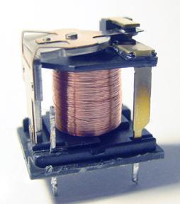
Contacts The moveable contact, which is the one affected by the armature is sometimes referred to as the hinge contact.
 Relays & Wiring 101 Basically, a relay is an electrically operated, remotely controlled switch. A simple electromagnetic relay is an adaptation of an electromagnet. It consists of a coil of wire surrounding
810 Industry S. Road Cocoa, FL 32926
 810 Industry S. Road Cocoa, FL 32926 U-PULL-IT PRICE SHEET Even though we do our best to keep our prices competitive and updated, they are subject to change without notice. If you have any questions regarding
14A6816H190 GT-2150 (2003) Page 1 of 28 Carburetor
 Page 1 of 28 Carburetor") 14A6816H190 GT-2150 (2003) Page 1 of 28 Carburetor 14A6816H190 GT-2150 (2003) Page 2 of 28 Carburetor TC-640221 1 /P Carburetor (Incl 184 of Engine Parts Lists) 1 TC-640216 1 Throttle Shaft & Lever Assembly
14A6816H190 GT-2150 (2003) Page 1 of 28 Carburetor 14A6816H190 GT-2150 (2003) Page 2 of 28 Carburetor TC-640221 1 /P Carburetor (Incl 184 of Engine Parts Lists) 1 TC-640216 1 Throttle Shaft & Lever Assembly
PART - RETAIL SHOP C900 DAVID'S [78-94] 9000 PRICE [84-98] LIST NG900 [94-98] OG9-3 [99-03] 9-3SS [03-11] A/C Compressor
![PART - RETAIL SHOP C900 DAVID'S [78-94] 9000 PRICE [84-98] LIST NG900 [94-98] OG9-3 [99-03] 9-3SS [03-11] A/C Compressor](/thumbs/95/124876646.jpg "PART - RETAIL SHOP C900 DAVID'S [78-94] 9000 PRICE [84-98] LIST NG900 [94-98] OG9-3 [99-03] 9-3SS [03-11] A/C Compressor") PART - RETAIL SHOP C900 DAVID'S [78-94] 9000 PRICE [84-98] LIST NG900 [94-98] OG9-3 [99-03] 9-3SS [03-11] A/C Compressor 150-250 150-250 150-250 150-250 150-250 A/C Condensor A/C Miscellaneous Parts A/C
PART - RETAIL SHOP C900 DAVID'S [78-94] 9000 PRICE [84-98] LIST NG900 [94-98] OG9-3 [99-03] 9-3SS [03-11] A/C Compressor 150-250 150-250 150-250 150-250 150-250 A/C Condensor A/C Miscellaneous Parts A/C
LIFETIME WRAP. 5 Star Wrap Vehicle Service Contract
 LIFETIME WRAP 5 Star Wrap Vehicle Service Contract We go the extra mile so you can enjoy the drive The 5 Star Wrap Vehicle Service Contract provides additional protection to your dealer s Limited Lifetime
Electrical Systems. Introduction
 Electrical Systems Figure 1. Major Components of the Car s Electrical System Introduction Electricity is used in nearly all systems of the automobile (Figure 1). It is much easier to understand what electricity
CIRCUIT DIAGRAMS GROUP CONTENTS HOW TO READ CIRCUIT DIAGRAMS VANITY MIRROR LIGHT JUNCTION BLOCK...
 90-1 GROUP 90 CONTENTS HOW TO READ................................. 90-4 JUNCTION BLOCK.............. 90-10 JOINT CONNECTOR............. 90-12 CENTRALIZED JUNCTION........ 90-13 POWER DISTRIBUTION SYSTEM..
DESCRIPTION & OPERATION
 DESCRIPTION & OPERATION 1999-2000 STARTING & CHARGING SYSTEMS Generators & Regulators NOTE: This article also applies to Lexus LX470. For Lexus LX470, refer to Land Cruiser, unless otherwise indicated.
Classic Update Series
 Classic Update Series 1964-1966 Ford Mustang START HERE! PLEASE READ THIS EFORE STARTING INSTALLATION! This wiring kit is designed for ease of installation. Please read the guidelines below, EFORE STARTING
Fuse and Relay Information
 11 1 Fuse and Relay Information Central Junction Box (CJB) (14A067) PCM power Trailer tow, battery charge Starter (11450) Blower motor Rear window defrost F2.602 C270p F2.101 F2.107 F2.102 F2.108 F2.601
Index. Abbreviation list Alphabetical index What to do if
 Index Abbreviation list... 470 Alphabetical index... 471 What to do if...... 481 469 Abbreviation list Abbreviation/Acronym list ABBREVIATIONS ABS ACC ALR CRS DISP ECU EDR ELR GAWR GVWR I/M LATCH LED LSD
CHARGING SYSTEM 8C - 1 CHARGING SYSTEM CONTENTS
 TJ CHARGING SYSTEM 8C - 1 CHARGING SYSTEM CONTENTS page DESCRIPTION AND OPERATION BATTERY TEMPERATURE SENSOR... 2 CHARGING SYSTEM OPERATION... 1 ELECTRONIC VOLTAGE REGULATOR... 2 GENERATOR... 1 DIAGNOSIS
G ELECTRICAL WIRING ROUTING [5VZ FE] TOYOTA TACOMA (EWD517U) Position of Parts in Engine Compartment
![G ELECTRICAL WIRING ROUTING [5VZ FE] TOYOTA TACOMA (EWD517U) Position of Parts in Engine Compartment](/thumbs/82/86578697.jpg "G ELECTRICAL WIRING ROUTING [5VZ FE] TOYOTA TACOMA (EWD517U) Position of Parts in Engine Compartment") G ELECTRICAL WIRING ROUTING [5VZ FE] Position of Parts in Engine Compartment A 5 A/C Magnetic Clutch A 7 A/T Oil Temp. Sensor A22 ABS Actuator with ECU A23 Air Fuel Ratio Sensor (Bank 1 Sensor 1) A24 ADD
G ELECTRICAL WIRING ROUTING [5VZ FE] Position of Parts in Engine Compartment A 5 A/C Magnetic Clutch A 7 A/T Oil Temp. Sensor A22 ABS Actuator with ECU A23 Air Fuel Ratio Sensor (Bank 1 Sensor 1) A24 ADD
S/N 1H019H - 1H310H Page 1 of 33 46" Cutting Deck Assembly
 1180 S/N 1H019H - 1H310H Page 1 of 33 46" Cutting Deck Assembly 1180 S/N 1H019H - 1H310H Page 2 of 33 46" Cutting Deck Assembly 1 17982 1 S Reinforcement Spindle Plate 2 618-0430 1 S Spindle Assembly w/
Acura Plus Comprehensive & Major Component Coverage
 Acura Plus Comprehensive & Major Component Coverage ENGINE Cylinder block and all internal parts Cylinder heads and all internal parts Engine mounts Engine seals and gaskets Flywheel Intake and exhaust
Position of Parts in Engine Compartment
 ELECTRICAL WIRING ROUTING [5S FE] Position of Parts in Engine Compartment A 1 A/C Condenser Fan Motor E 4 Engine Coolant Temp. Sensor (EFI Water Temp. A 2 A/C Magnetic Clutch and Lock Sensor Sensor) A
Index. Abbreviation list Alphabetical index What to do if
 Index Abbreviation list... 478 Alphabetical index... 479 What to do if...... 489 477 Abbreviation list Abbreviation/Acronym list ABBREVIATIONS ABS ACC ALR CRS DISP ECU EDR ELR GAWR GVWR I/M LATCH LED LSD
Supercharged MK1 MR2 Part Diagrams
 Supercharged MK1 MR2 Part Diagrams Created by: Charles K. (ckowalc) 1 Table of Contents PART DIAGRAM PAGE ACCELERATOR LINK 9 AIR CLEANER 10 AIR CLEANER 4AGZE 11 ALTERNATOR 4AGZE 12 ANTENNA 13 ARMREST &
A/C-HEATER SYSTEM - AUTOMATIC
 A/C-HEATER SYSTEM - AUTOMATIC 1988 Toyota Celica 1988 Automatic A/C-Heater Systems Celica * PLEASE READ THIS FIRST * CAUTION: When discharging air conditioning system, use only approved refrigerant recovery/recycling
Passat Fitting Locations No. 208 / 1 Edition
 Sivu 1/11 Passat Fitting Locations No. 208 / 1 Edition 02.2007 Relay and fuse assignment From May 2002 Relay locations on 13 position additional relay carrier above relay plate 1 - Radiator fan relay -
1 of 15 C:\Users\sny\Downloads\2019 Used Parts Price List.ods
 PART - RETAIL SHOP C900 DAVID'S [78-94] 9000 PRICE [84-98] LIST NG900 [94-98] OG9-3 [99-03] 9-3SS [03-11] A/C Compressor 150-250 150-250 150-250 150-250 150-250 A/C Condensor A/C Miscellaneous Parts A/C
G ELECTRICAL WIRING ROUTING [2ZZ GE] Position of Parts in Engine Compartment
![G ELECTRICAL WIRING ROUTING [2ZZ GE] Position of Parts in Engine Compartment](/thumbs/82/84806793.jpg "G ELECTRICAL WIRING ROUTING [2ZZ GE] Position of Parts in Engine Compartment") G ELECTRICAL WIRING ROUTING [2ZZ GE] Position of Parts in Engine Compartment A 1 A/C Magnetic Clutch A 2 ABS Speed Sensor Front LH A 3 ABS Speed Sensor Front RH A 4 Airbag Sensor Front LH A 5 Airbag Sensor
G ELECTRICAL WIRING ROUTING [2ZZ GE] Position of Parts in Engine Compartment A 1 A/C Magnetic Clutch A 2 ABS Speed Sensor Front LH A 3 ABS Speed Sensor Front RH A 4 Airbag Sensor Front LH A 5 Airbag Sensor
Volkswagen Cabriolet DIY Guide Relay/Fuse Diagrams & Electrical System
 Volkswagen Cabriolet DIY Guide Relay/Fuse Diagrams & Electrical System Notes: 1980-1982 cars use ceramic fuses! 1980-1982 cars had a recall for the fuel pump relay. These cars should have a relay bypass
Position of Parts in Engine Compartment
 ELECTRICAL WIRING ROUTING [5S FE] Position of Parts in Engine Compartment A 1 A/C Ambient Temp. Sensor D 1 Distributor A 2 A/C Condenser Fan Motor A 3 A/C Idle Up VSV E 1 ECT Solenoid A 4 A/C Magnet Clutch