INTRODUCTION Principle
|
|
|
- Curtis Bradley
- 6 years ago
- Views:
Transcription
1 DC Generators INTRODUCTION A generator is a machine that converts mechanical energy into electrical energy by using the principle of magnetic induction. Principle Whenever a conductor is moved within a magnetic field in such a way that the conductor cuts across magnetic lines of flux, voltage is generated in the conductor.
2 The AMOUNT of Generated Voltage depends upon: 1) The strength of the magnetic field, (2) The angle at which the conductor cuts the magnetic field, (3) The speed at which the conductor is moved, and (4) The length of the conductor within the magnetic field.
3 POLARITY of the voltage depends on : The direction of the magnetic lines of flux and The direction of movement of the conductor. How to determine the direction of current in a given situation?

4 Figure - Left-hand rule for generators.
5 Left Hand Rule of Generators Extend the thumb, forefinger, and middle finger of your left hand at right angles to one another Point your forefinger in the direction of magnetic flux (from north to south). Your middle finger will then point in the direction of current flow in an external circuit to which the voltage is applied
6 THE ELEMENTARY GENERATOR An elementary generator consists of a wire loop placed so that it can be rotated in a stationary magnetic field. This will produce an induced emf in the loop. Sliding contacts (brushes) connect the loop to an external circuit load in order to pick up or use the induced emf.

7 Figure - The elementary generator.
8 The pole pieces (marked N and S) provide the magnetic field. The pole pieces are shaped and positioned (as shown ) to concentrate the magnetic field as close as possible to the wire loop. The loop of wire that rotates through the field is called the ARMATURE. The ends of the armature loop are connected to rings called SLIP RINGS. They rotate with the armature. The brushes, usually made of carbon, with wires attached to them, ride against the rings. The generated voltage appears across these brushes.
9 The elementary generator produces a voltage in the following manner (as shown in figure beleow). The armature loop is rotated in a clockwise direction. The initial or starting point is shown at position A. (This will be considered the zero-degree position.) At 0 the armature loop is perpendicular to the magnetic field. The black and Red conductors of the loop are moving parallel to the field. The instant the conductors are moving parallel to the magnetic field, they do not cut any lines of flux. Therefore, no emf is induced in the conductors, and the meter at position A indicates zero. This position is called the NEUTRAL PLANE.

10 Output Voltage of An Elementary Generator Figure - Output voltage of an elementary generator during one revolution.
11 As the armature loop rotates from position A (0 ) to position B (90 ), the conductors cut through more and more lines of flux, at a continually increasing angle. At 90 they are cutting through a maximum number of lines of flux and at maximum angle. The result is that between 0 and 90, the induced emf in the conductors builds up from zero to a maximum value. Observe that from 0 to 90, the black conductor cuts UP through the field. At the same time the RED conductor cuts DOWN through the field. The induced emfs in the conductors are seriesadding. This means the resultant voltage across the brushes (the terminal voltage) is the sum of the two induced voltages. The meter at position B reads maximum value.
12 As the armature loop continues rotating from 90 (position B) to 180 (position C), the conductors which were cutting through a maximum number of lines of flux at position B now cut through fewer lines. They are again moving parallel to the magnetic field at position C. They no longer cut through any lines of flux. As the armature rotates from 90 to 180, the induced voltage will decrease to zero in the same manner that it increased during the rotation from 0 to 90
13 The meter again reads zero. From 0 to 180 the conductors of the armature loop have been moving in the same direction through the magnetic field. Therefore, the polarity of the induced voltage has remained the same. This is shown by points A through C on the graph. As the loop rotates beyond 180 (position C), through 270 (position D), and back to the initial or starting point (position A), the direction of the cutting action of the conductors through the magnetic field reverses.
14 Now the black conductor cuts DOWN through the field while the RED conductor cuts UP through the field. As a result, the polarity of the induced voltage reverses. Following the sequence shown by graph points C, D, and back to A, the voltage will be in the direction opposite to that shown from points A, B, and C. The terminal voltage will be the same as it was from A to C except that the polarity is reversed (as shown by the meter deflection at position D). The voltage output waveform for the complete revolution of the loop is shown on the graph.
15 THE ELEMENTARY DC GENERATOR A single-loop generator with each terminal connected to a segment of a two-segment metal ring is shown in figure below. The two segments of the split metal ring are insulated from each other. This forms a simple COMMUTATOR. The commutator in a dc generator replaces the slip rings of the ac generator. This is the main difference in their construction. The commutator mechanically reverses the armature loop connections to the external circuit

16 Figure. - Effects of commutation.
17 This occurs at the same instant that the polarity of the voltage in the armature loop reverses. Through this process the commutator changes the generated ac voltage to a pulsating dc voltage. This action is known as commutation. When the armature loop rotates clockwise from position A to position B, a voltage is induced in the armature loop which causes a current in a direction that deflects the meter to the right
18 Current flows through loop, out of the negative brush, through the meter and the load, and back through the positive brush to the loop. Voltage reaches its maximum value at point B on the graph, the generated voltage and the current fall to zero at position C. At this instant each brush makes contact with both segments of the commutator. As the armature loop rotates to position D, a voltage is again induced in the loop. In this case, however, the voltage is of opposite polarity
19 The voltages induced in the two sides of the coil at position D are in the reverse direction to that of the voltages shown at position B.
20 The voltage developed across the brushes is pulsating and unidirectional (in one direction only). It varies twice during each revolution between zero and maximum. This variation is called RIPPLE. A pulsating voltage, is not suitable for most applications. Therefore, in practical generators more armature loops (coils) and more commutator segments are used to produce an output voltage waveform with less ripple.
21 EFFECTS OF ADDING ADDITIONAL COILS AND POLES The effects of additional coils can be illustrated by the addition of a second coil to the armature. The commutator must now be divided into four parts since there are four coil ends The coil is rotated in a clockwise direction from the position shown. The voltage induced in the white coil, DECREASES FOR THE NEXT 90 of rotation (from maximum to zero). The voltage induced in the black coil INCREASES from zero to maximum at the same time. Since there are four segments in the commutator, a new segment passes each brush every 90 instead of every 180.

22 Figure - Effects of additional coils
23 This allows the brush to switch from the white coil to the black coil at the instant the voltages in the two coils are equal. The brush remains in contact with the black coil as its induced voltage increases to maximum, level B in the graph. It then decreases to level A, 90 later. At this point, the brush will contact the white coil again The graph in above figure shows the ripple effect of the voltage when two armature coils are used. Since there are now four segments in the commutator and only two brushes, the voltage cannot fall any lower than at point A. Therefore, the ripple is limited to the rise and fall between points A and B on the graph. By adding more armature coils, the ripple effect can be further reduced. Decreasing ripple in this way increases the voltage of the output.
24 NOTE: By using additional armature coils, the voltage across the brushes is not allowed to fall to as low a level between peaks. Practical generators use many armature coils. They also use more than one pair of magnetic poles. The additional magnetic poles have the same effect on ripple as did the additional armature coils. The increased number of poles provides a stronger magnetic field (greater number of flux lines). This, in turn, allows an increase in output voltage because the coils cut more lines of flux per revolution.
25 ELECTROMAGNETIC POLES Nearly all practical generators use electromagnetic poles instead of the permanent magnets. The electromagnetic field poles consist of coils of insulated copper wire wound on soft iron cores, as shown in figure below. Main advantages of using electromagnetic poles are: (1) Increased field strength and (2) A means of controlling the strength of the fields. By varying the input voltage, the field strength is varied. By varying the field strength, the output voltage of the generator can be controlled.

26 Figure - Four-pole generator (without armature).
27 COMMUTATION Commutation is the process by which a dc voltage output is taken from an armature that has an ac voltage induced in it. The commutator mechanically reverses the armature loop connections to the external circuit. This occurs at the same instant that the voltage polarity in the armature loop reverses. A dc voltage is applied to the load because the output connections are reversed as each commutator segment passes under a brush. The segments are insulated from each other.

28 Figure - Commutation of a DC Generator
29 In above figure, commutation occurs simultaneously in the two coils that are briefly short-circuited by the brushes. Coil B is short-circuited by the negative brush. Coil Y, the opposite coil, is short-circuited by the positive brush. The brushes are positioned on the commutator so that each coil is short-circuited as it moves through its own electrical neutral plane. So no sparking can occur between the commutator and the brush. Note: Sparking between the brushes and the commutator is an indication of improper commutation. Improper brush placement is the main cause of improper commutation.
30 ARMATURE REACTION The magnetic field produced by current in the armature of a dc generator affects the flux pattern and distorts the main field. This distortion causes a shift in the neutral plane, which affects commutation. This change in the neutral plane and the reaction of the magnetic field is called ARMATURE REACTION. For proper commutation, the coil short-circuited by the brushes must be in the neutral plane.
with the cross section of its coil represented as little circles. The symbols within the circles represent arrows.")
31 Figure - Armature reaction. Consider the operation of a simple two-pole dc generator, shown above. View A of the figure shows the field poles and the main magnetic field. The armature is shown in a simplified view in views B (and C )with the cross section of its coil represented as little circles. The symbols within the circles represent arrows. The dot represents the point of the arrow coming out of the plane, and the cross represents the tail, going into the plane.
32 When the armature rotates clockwise, the sides of the coil to the left will have current flowing toward you, as indicated by the dot. The side of the coil to the right will have current flowing away from you, as indicated by the cross. The field generated around each side of the coil is shown in view B of above figure. This field increases in strength for each wire in the armature coil, and sets up a magnetic field almost perpendicular to the main field.
33 Now you have two fields The main field, view A, and The field around the armature coil, view B. View C shows how the armature field distorts the main field and how the neutral plane is shifted in the direction of rotation. If the brushes remain in the old neutral plane, they will be short-circuiting coils that have voltage induced in them. Consequently, there will be arcing between the brushes and commutator. To prevent arcing, the brushes must be shifted to the new neutral plane.
34 How to reduce the Armature Rection? Shifting the brushes to the advanced position (the new neutral plane) does not completely solve the problems of armature reaction. The effect of armature reaction varies with the load current. Therefore, each time the load current varies, the neutral plane shifts. This means the brush position must be changed each time the load current varies. In small generators, the effects of armature reaction are reduced by actually mechanically shifting the position of the brushes. The practice of shifting the brush position for each current variation is not practiced except in small generators.
35 Armature Reaction Reduction Techniques in Large Generators Mainly there are two techniques to reduce the armature reaction in the large DC machines 1. Compensating Windings 2. Inter-poles
36 Compensating Windings The compensating windings consist of a series of coils embedded in slots in the pole faces. These coils are connected in series with the armature. The series-connected compensating windings produce a magnetic field, which varies directly with armature current. Because the compensating windings are wound to produce a field that opposes the magnetic field of the armature, they tend to cancel the effects of the armature magnetic field.
37 The neutral plane will remain stationary and in its original position for all values of armature current. Because of this, once the brushes have been set correctly, they do not have to be moved again.

38 Figure - Compensating windings and inter-poles.
39 Inter-Poles Small auxiliary poles called "interpoles" are Places between the main field poles. The inter-poles have a few turns of large wire and are connected in series with the armature. Interpoles are wound and placed so that each interpole has the same magnetic polarity as the main pole ahead of it, in the direction of rotation. The field generated by the interpoles cancels the armature reaction for all values of load current by causing a shift in the neutral plane opposite to the shift caused by armature reaction. The amount of shift caused by the interpoles will equal the shift caused by armature reaction since both shifts are a result of armature current
40 MOTOR REACTION IN A GENERATOR When a generator delivers current to a load, the armature current creates a magnetic force that opposes the rotation of the armature. This is called MOTOR REACTION. When a single conductor is stationary, no voltage is generated and no current flows ( as shown in figure below). Therefore, no force acts on the conductor. When the conductor is moved downward and the circuit is completed through an external load, current flows through the conductor in the direction indicated. This sets up lines of flux around the conductor.

41 Figure - Motor reaction in a generator.
42 The interaction between the conductor field and the main field of the generator weakens the field above the conductor and strengthens the field below the conductor. The main field consists of lines that now act like stretched rubber bands. Thus, an upward reaction force is produced that acts in opposition to the downward driving force applied to the armature conductor. If the current in the conductor increases, the reaction force increases. Therefore, more force must be applied to the conductor to keep it moving.
43 With no armature current, there is no magnetic (motor) reaction. Therefore, the force required to turn the armature is low. As the armature current increases, the reaction of each armature conductor against rotation increases. The actual force in a generator is multiplied by the number of conductors in the armature. The driving force required to maintain the generator armature speed must be increased to overcome the motor reaction. The force applied to turn the armature must overcome the motor reaction force in all dc generators. The device that provides the turning force applied to the armature is called the PRIME MOVER.
44 Different Terminologies used in Machines A Conductor: Each Individual Length of wire lying within the magnetic field is called a conductor Turn: When two conductors lying in a magnetic field are connected in series, so that EMF induced in them help each other or resulting EMF becomes double( Assuming full pitch Winding) to that due to one conductor is known as turn.
45 Coil: One or More turns of wire Grouped together and mounted on the armature in order to cut the lines of flux is called coil. Pole Pitch: The Distance Between Identical Points on adjacent poles is called pole pitch Commutator Pitch Y c : The Number of commutator segments spanned from one end of a coil to the other end of the same coil is called commutator pitch
46 Full Pitch Coil: If a coil Covers a Span of 180 o electrical and the voltage induced in the conductors on both sides of the coil will be same in magnitude but opposite in direction, then it is called a full pitch coil. Fractional Pitch Coil: If a Coil covers a span of less than 180 o Electrical then it is called a fractional pitch coil and a rotor winding done with fractional pitch coils is called chorded winidng
47 Pitch Factor: P = (Electrical Angle of coil / 180 o )x 100%. A coil having a span of 160 o electrical would have a pitch factor of 160 o /180 o = Relationship between Electrical & Mechanical Angle: The Relationship between Electrical and Mechanical Degrees is: θ e = (P/2 ) θ m θ e Electrical angle in degrees θ m Mechanical angle in degrees P Number if Poles on the DC Machine
48 Two Layer Winding: In the two layer Winding, sides from two different coils are inserted into each slot. One side of each coil will be at the bottom of its own slot and the other side will be at the top of other slot.
49 Front End Connection: A wire that connects the end of a coil to a commutator segment. This wire is located at that part of the coil which is nearest to the commutator. Back End Connection: A wire or conductor that connects one side of coil to the other side of the coil. It is on the end opposite to the commutator. Front Pitch (y f ): The distance measured along the armature from one coil side to another coil side, the ends of which are connected to the same commutator segment.the distance is measured in coil sides or slots.
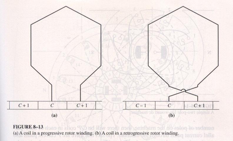
50 Back Pitch (y p ): The number of coil sides or slots spanned by the back end connection. Progressive Winding If the end of a coil is ( or a set number of coils for wave winding) is connected to a commutator segment after the one, its beginning is connected to, the winding is called a progressive winding. Retrogressive Winding If the end of a coil is connected to a commutator segment before the one its beginning is connected to, the winding is called retrogressive winding.
51
52 Simplex Rotor Winding: A single complete closed winding wound on a rotor is called a simplex rotor winding. Duplex Rotor Winding A rotor winding with two complete and independent sets of windings is called a duplex rotor winding 1, 3, 5, 7 one Layer of winding 2, 4, 6, 8 second Layer of Winding Y = + 2 for Progressive winding Y = -2 for Retrogressive winding. Triplex Rotor Winding A Triplex winding will have three complete and independent sets of rotor windings.
53 In General: For m plex LAP winding, the commutator pitch Y c = ± m Number of Current paths in a machine a = mp for LAP winding a # of current paths in rotor m Plex of the winding ( 1,2,3 ) P Poles on the machine.
54 Types of Armature Winding There are two types of armature windings: 1. Open Coil Winding 2. Closed Coil Winding Open Coil Windings: A winding which doesn t close on itself. it is used in AC machines. Closed Coil Winding: A winding which closes on itself. This type of winding is used in DC machines.
55 Types of Closed Armature Windings 1. Ring Winding 2. Drum Winding Ring winding: Armature winding in which the wire is wound round the outer and inner surfaces alternately of a cylindrical core. Drum winding: A method of armature winding in which the wire is wound upon the outer surface of a cylinder or drum from end to end of the cylinder.
56 Disadvantages of Ring Winding Increased Consumption of Copper Difficult conditions of Cooling High cost of Repair and Maintenance Insulation of winding is more difficult Large air gap due to construction, requires stronger field for a certain flux. For same Pole flux and armature velocity, the emf induced in the ring winding is half of that induced in the drum winding having same number of coils
57 Advantages of Drum Winding All armature copper except the end connections is active in generating emf. The coils can be pre-formed and insulated before placing on the armature and hence the cost is reduced. Types of Drum Windings There are two types of drum windings 1. LAP Winding 2. Wave Winding
58 LAP Winding ( Simplex Series Wdg) A winding in which the two ends of a coil are connected to the two adjacent commutator segments Commutator Pitch Y c = 1 for Progressive Winding Y c = -1 for Retrogressive Winding In the Simplex LAP winding, there are as many parallel current paths an many poles on the machine. The Number of brushes will also be equal to the number of parallel current paths in the machine.
59
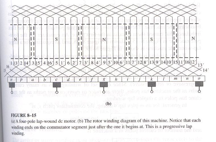
60 Figure Four Pole LAP wound DC Motor
61
62 In a P pole machine, if there are C Commutator segments and coils on the armature, then there will be C/P coils in each current path. Duplex LAP winding has two independent sets of windings on the rotor ( Yc = ± 2 ). Each set of winding has as many current paths as the poles on the machine. In the duplex winding, the number of current paths are double of the number of poles on the machine. In General, For m-plex LAP winding Commutator Pitch Y c = ± m for lap Winding and the number of current paths are a = mp where m is the plex of winding Uses of LAP Windings: LAP windings are suitable for high current and low voltages machines.
63 Problems of Multi-pole LAP wound machines Long usage of the multipole machine causes wear on the bearings of the machine. As a result there is large voltage in the current paths involving wires under the lower pole faces than in the paths involving wires under the upper pole face. So there will be circulating currents flowing out some of the brushes in the machine and back in to the others. Imbalance in voltage will cause large circulating currents through brushes, as a result there will be overheating problems in the machine.
64
65
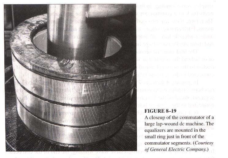
66 How to solve the Problems of Circulating Currents in LAP wound Machines? It is not possible to solve the problem of circulating current completely, however it can be reduced by equalizers or equalizing windings. Equalizers are bars placed on the rotor of the LAP wound DC machine that short together the points at the same voltage level in the different parallel paths. Due this short circuiting, the circulating current remains with in the small section of the winding and does t flow through the brushes.
67 The circulating currents ( which are confined within the small region in the winding ) also reduce the flux imbalance which is responsible for creating these circulating currents at first place.
68
69
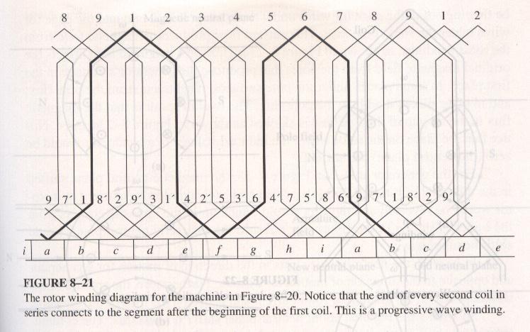
70 Wave Winding In simplex wave winding, every other rotor coil connects back to a commutator segment adjacent to the beginning of the first coil. Progressive Wave Winding If the second coil is connected to the comutator segment after the first coil, the winding is called Progressive wave winding. Retrogressive Wave Winding. If the second coil is connected to the comutator segment before the first coil, the winding is called retrogressive wave winding.
71
72
73 In a simplex wave winding, the brushes will be located a full pole pitch apart from each other and there will be only two current paths For a P pole machine there will be P/2 coils in series between adjacent commutator segment. Commutator Pitch for a Wave Winding: The commutator pitch for any simplex wave winding is: Yc = 2(C ± 1) / P C Number of Coils on the rotor P Number of Poles on the machine + For Progressive wave Winding - For Retrogressive Wave Winding
74 In a Simplex wave wound rotor, there are two brushes to draw off the current. Additional brushes can be connected at 180 o apart from each other. Extra brushes reduce the amount of current that must be drawn through a given brush set. Uses of WAVE Windings: Wave windings are used for high voltage DC machines, because, the series connection of coils helps in building high voltages. Multiplex WAVE Windings: Multiplex wave winding is a winding with multiple independent sets of wave windings on the rotor. Number of Current Paths a = 2m
75 The Frog-Leg Windings The Frog-Leg or self equalizing winding combines the LAP and Wave windings in such a way that the wave winding can function as equalizers for the LAP winding. The Number of Current paths in a Frog-Leg wave winding are a = 2*P*m LAP P Number of poles m LAP Plex of the LAP winding
76 EMF Equation of a DC Generator The voltage generated by the Generator depends upon: 1. The Strength of the magnetic field 2. The angle at which the conductor cuts the lines of flux. 3. The speed at which the conductor is moved in the magnetic field or the Speed at which the conductor cuts the lines of flux. 4. The of the conductor in the magnetic field
77
78
79
80
81
82
83
84
85
86
87
88
89
90
91
92
93
94
UNIT 2. INTRODUCTION TO DC GENERATOR (Part 1) OBJECTIVES. General Objective
 OBJECTIVES. General Objective") DC GENERATOR (Part 1) E2063/ Unit 2/ 1 UNIT 2 INTRODUCTION TO DC GENERATOR (Part 1) OBJECTIVES General Objective : To apply the basic principle of DC generator, construction principle and types of DC generator.
DC GENERATOR (Part 1) E2063/ Unit 2/ 1 UNIT 2 INTRODUCTION TO DC GENERATOR (Part 1) OBJECTIVES General Objective : To apply the basic principle of DC generator, construction principle and types of DC generator.
CHAPTER 6 INTRODUCTION TO MOTORS AND GENERATORS
 CHAPTER 6 INTRODUCTION TO MOTORS AND GENERATORS Objective Describe the necessary conditions for motor and generator operation. Calculate the force on a conductor carrying current in the presence of the
BELT-DRIVEN ALTERNATORS
 CHAPTER 13 BELT-DRIVEN ALTERNATORS INTRODUCTION A generator is a machine that converts mechanical energy into electrical energy using the principle of magnetic induction. This principle is based on the
Question 2: Around the bar magnet draw its magnetic fields. Answer:
 Chapter 13: Magnetic Effects of Electric Current Question 1: What is the reason behind the compass needle is deflected when it is brought close to the bar magnet? Compass needles work as a small bar magnet;
Historical Development
 TOPIC 3 DC MACHINES DC Machines 2 Historical Development Direct current (DC) motor is one of the first machines devised to convert electrical power into mechanical power. Its origin can be traced to the
MAGNETIC EFFECTS OF ELECTRIC CURRENT
 MAGNETIC EFFECTS OF ELECTRIC CURRENT It is observed that when a compass is brought near a current carrying conductor the needle of compass gets deflected because of flow of electricity. This shows that
EE6352-ELECTRICAL ENGINEERING AND INSTRUMENTATION UNIT I D.C. MACHINES PART A
 EE6352-ELECTRICAL ENGINEERING AND INSTRUMENTATION 1. What is prime mover? UNIT I D.C. MACHINES PART A The basic source of mechanical power which drives the armature of the generator is called prime mover.
DC Generator. - The direction of current flow in the conductor is given by Fleming s right hand rule. Figure 2: Change in current direction
 DC Generator 1. THE DIRECTION OF CURRENT DUE TO INDUCED VOLTAGE: UNDERSTANDING FLEMING S RIGHT HAND RULE - The direction of current flow in the conductor is given by Fleming s right hand rule Figure 1:
SSC-JE STAFF SELECTION COMMISSION ELECTRICAL ENGINEERING STUDY MATERIAL ELECTRICAL MACHINES
 1 SSC-JE STAFF SELECTION COMMISSION ELECTRICAL ENGINEERING STUDY MATERIAL 28-B/7, Jia Sarai, Near IIT, Hauz Khas, New Delhi-110016. Ph. 011-26514888. www.engineersinstitute.com 2 CONTENT 1. : DC MACHINE,
UNIT I D.C. MACHINES PART A. 3. What are factors on which hysteresis loss? It depends on magnetic flux density, frequency & volume of the material.
 EE6352-ELECTRICAL ENGINEERING AND INSTRUMENTATION UNIT I D.C. MACHINES PART A 1. What is prime mover? The basic source of mechanical power which drives the armature of the generator is called prime mover.
D.C. Generators. Chapter (1) Introduction. 1.1 Generator Principle. 1.2 Simple Loop Generator
 Introduction. 1.1 Generator Principle. 1.2 Simple Loop Generator") Chapter (1) D.C. Generators Introduction Although a far greater percentage of the electrical machines in service are a.c. machines, the d.c. machines are of considerable industrial importance. The principal
Chapter (1) D.C. Generators Introduction Although a far greater percentage of the electrical machines in service are a.c. machines, the d.c. machines are of considerable industrial importance. The principal
SPH3U UNIVERSITY PHYSICS
 SPH3U UNIVERSITY PHYSICS ELECTRICITY & MAGNETISM L (P.599-604) The large-scale production of electrical energy that we have today is possible because of electromagnetic induction. The electric generator,
DC MOTOR. Prashant Ambadekar
 DC MOTOR Prashant Ambadekar Electric Motor: The input is electrical energy (from the supply source), and the output is mechanical energy (to the load). Electric Generator: The Input is mechanical energy
Principles of Electrical Engineering
 D.C GENERATORS Principle of operation of D.C machines, types of D.C Generators, e.m.f equation of D.C Generator, O.C.C of a D.C Shunt Generator, Load characteristics of D.C.Generators GENERATOR PRINCIPLE:
Page 1 of 19. Website: Mobile:
 Question 1: Why does a compass needle get deflected when brought near a bar magnet? A compass needle is a small bar magnet. When it is brought near a bar magnet, its magnetic field lines interact with
Intext Exercise 1 Question 1: Why does a compass needle get deflected when brought near a bar magnet?
 Intext Exercise 1 Why does a compass needle get deflected when brought near a bar magnet? A compass needle is a small bar magnet. When it is brought near a bar magnet, its magnetic field lines interact
2 Principles of d.c. machines
 2 Principles of d.c. machines D.C. machines are the electro mechanical energy converters which work from a d.c. source and generate mechanical power or convert mechanical power into a d.c. power. These
Magnetic Effects of Electric Current
 Magnetic Effects of Electric Current Question 1: Why does a compass needle get deflected when brought near a bar magnet? Answer: A compass needle is a small bar magnet. When it is brought near a bar magnet,
ECEg439:-Electrical Machine II
 ECEg439:-Electrical Machine II 2.2 Main Structural Elements of DC Machine Construction of DC Machines A DC machine consists of two main parts 1. Stationary Part (Stator):-It is designed mainly for producing
DESIGN OF DC MACHINE
 DESIGN OF DC MACHINE 1 OUTPUT EQUATION P a = power developed by armature in kw P = rating of machine in kw E = generated emf, volts; V = terminal voltage, volts p = number of poles; I a = armaure current,
AP Physics B: Ch 20 Magnetism and Ch 21 EM Induction
 Name: Period: Date: AP Physics B: Ch 20 Magnetism and Ch 21 EM Induction MULTIPLE CHOICE. Choose the one alternative that best completes the statement or answers the question. 1) If the north poles of
CHAPTER THREE DC MOTOR OVERVIEW AND MATHEMATICAL MODEL
 CHAPTER THREE DC MOTOR OVERVIEW AND MATHEMATICAL MODEL 3.1 Introduction Almost every mechanical movement that we see around us is accomplished by an electric motor. Electric machines are a means of converting
CHAPTER 13 MAGNETIC EFFECTS OF ELECTRIC CURRENT
 CHAPTER 13 MAGNETIC EFFECTS OF ELECTRIC CURRENT Compass needle:- It is a small bar magnet, whose north end is pointing towards north pole and south end is pointing towards south pole of earth..hans Oersted
DC Motor and Generator Theory By
 DC Principles Study Unit DC Motor and Generator Theory By Robert Cecci iii Preview DC motors and generators are widely used in industrial applications. Both motors and generators are devices that produce
Permanent Magnet DC Motor Operating as a Generator
 Exercise 2 Permanent Magnet DC Motor Operating as a Generator EXERCIE OBJECTIVE When you have completed this exercise, you will be familiar with the construction of permanent magnet dc motors as well as
Note 8. Electric Actuators
 Note 8 Electric Actuators Department of Mechanical Engineering, University Of Saskatchewan, 57 Campus Drive, Saskatoon, SK S7N 5A9, Canada 1 1. Introduction In a typical closed-loop, or feedback, control
2006 MINI Cooper S GENINFO Starting - Overview - MINI
 MINI STARTING SYSTEM * PLEASE READ THIS FIRST * 2002-07 GENINFO Starting - Overview - MINI For information on starter removal and installation, see the following articles. For Cooper, see STARTER WITH
1. Why does a compass needle get deflected when brought near a bar magnet?
 1. Why does a compass needle get deflected when brought near a bar magnet? The needle of a compass is a small magnet. That s why when a compass needle is brought near a bar magnet, its magnetic field lines
Permanent Magnet DC Motor
 Renewable Energy Permanent Magnet DC Motor Courseware Sample 86357-F0 A RENEWABLE ENERGY PERMANENT MAGNET DC MOTOR Courseware Sample by the staff of Lab-Volt Ltd. Copyright 2011 Lab-Volt Ltd. All rights
Chapter 22: Electric motors and electromagnetic induction
 Chapter 22: Electric motors and electromagnetic induction The motor effect movement from electricity When a current is passed through a wire placed in a magnetic field a force is produced which acts on
Basic Motor Theory. Introduction
 Basic Motor Theory Introduction It has been said that if the Ancient Romans, with their advanced civilization and knowledge of the sciences, had been able to develop a steam motor, the course of history
Navy Electricity and Electronics Training Series
 NONRESIDENT TRAINING COURSE Navy Electricity and Electronics Training Series Module 5 Introduction to Generators and Motors NAVEDTRA 14177 DISTRIBUTION STATEMENT A: Approved for public release; distribution
Magnetic Effects of Electric Current
 CHAPTER13 Magnetic Effects of Electric Current Multiple Choice Questions 1. Choose the incorrect statement from the following regarding magnetic lines of field (a) The direction of magnetic field at a
ELECTRO MAGNETIC INDUCTION
 6 ELECTRO MAGNETIC INDUCTION 06.01 Electromagnetic induction When the magnetic flux linked with a coil or conductor changes, an emf is developed in it. This phenomenon is known as electromagnetic induction.
Describe an experiment to demonstrate that there is a magnetic field around a current carrying conductor.
 EXERCISE 10 (A) Question 1: Describe an experiment to demonstrate that there is a magnetic field around a current carrying conductor. Solution 1: Experiment: In Fig, AB is a wire lying in the north- south
EXPERIMENT 13 QUALITATIVE STUDY OF INDUCED EMF
 220 13-1 I. THEORY EXPERIMENT 13 QUALITATIVE STUDY OF INDUCED EMF Along the extended central axis of a bar magnet, the magnetic field vector B r, on the side nearer the North pole, points away from this
2014 ELECTRICAL TECHNOLOGY
 SET - 1 II B. Tech I Semester Regular Examinations, March 2014 ELECTRICAL TECHNOLOGY (Com. to ECE, EIE, BME) Time: 3 hours Max. Marks: 75 Answer any FIVE Questions All Questions carry Equal Marks ~~~~~~~~~~~~~~~~~~~~~~~~~~
MAGNETIC EFFECTS OF ELECTRIC CURRENT. To understand Magnetic effects of Electric current, first we should know what is the Magnet?
 MAGNETIC EFFECTS OF ELECTRIC CURRENT To understand Magnetic effects of Electric current, first we should know what is the Magnet? Magnet A Magnet is an object which attracts pieces of iron, steel, nickel
1. What type of material can be induced to become a temporary magnet? A) diamagnetic B) ferromagnetic C) monomagnetic D) paramagnetic
 diamagnetic B) ferromagnetic C) monomagnetic D) paramagnetic") Assignment 1 Magnetism and Electromagnetism Name: Multiple Choice Identify the letter of the choice that best completes the statement or answers the question. Show appropriate workings. 1. What type of
Assignment 1 Magnetism and Electromagnetism Name: Multiple Choice Identify the letter of the choice that best completes the statement or answers the question. Show appropriate workings. 1. What type of
CHAPTER -13 MAGNETIC EFFECT OF ELECTRIC CURRENT
 CHAPTER -13 MAGNETIC EFFECT OF ELECTRIC CURRENT Madhu:8095226364 Question 1: Why does a compass needle get deflected when brought near a bar magnet? Answer 1: Magnetic compass needle and bar magnet both
Motional emf. as long as the velocity, field, and length are mutually perpendicular.
 Motional emf Motional emf is the voltage induced across a conductor moving through a magnetic field. If a metal rod of length L moves at velocity v through a magnetic field B, the motional emf is: ε =
FARADAY S LAW ELECTROMAGNETIC INDUCTION
 FARADAY S LAW ELECTROMAGNETIC INDUCTION magnetic flux density, magnetic field strength, -field, magnetic induction [tesla T] magnetic flux [weber Wb or T.m 2 ] A area [m 2 ] battery back t T f angle between
MAGNETIC EFFECTS OF CURRENT
 Magnet A magnet is an object, which attracts pieces of iron, steel, nickel and cobalt. Naturally Occurring Magnet Lodestone is a naturally occurring magnet. It is actually a black coloured, oxide ore of
MAGNETIC EFFECT OF ELECTRIC CURRENT
 BAL BHARATI PUBLIC SCHOOL, PITAMPURA Class X MAGNETIC EFFECT OF ELECTRIC CURRENT 1. Magnetic Field due to a Current through a Straight Conductor (a) Nature of magnetic field: The magnetic field lines due
INDUCTANCE FM CHAPTER 6
 CHAPTER 6 INDUCTANCE INTRODUCTION The study of inductance is a very challenging but rewarding segment of electricity. It is challenging because at first it seems that new concepts are being introduced.
Electrical Machines -II
 Objective Type Questions: 1. Basically induction machine was invented by (a) Thomas Alva Edison (b) Fleming (c) Nikola Tesla (d) Michel Faraday Electrical Machines -II 2. What will be the amplitude and
Relay. for Experiments with the fischertechnik Expansion Kit. Order No
 Relay for Experiments with the fischertechnik Expansion Kit Order No. 30075 About the Relay A relay is an electromagnetic switch. It consists essentially of two assemblies. 5 6 7 3 2 1. Technical Data
EEE3441 Electrical Machines Department of Electrical Engineering. Lecture. Introduction to Electrical Machines
 Department of Electrical Engineering Lecture Introduction to Electrical Machines 1 In this Lecture Induction motors and synchronous machines are introduced Production of rotating magnetic field Three-phase
Figure 1: Forces Are Equal When Both Their Magnitudes and Directions Are the Same
 Moving and Maneuvering 1 Cornerstone Electronics Technology and Robotics III (Notes primarily from Underwater Robotics Science Design and Fabrication, an excellent book for the design, fabrication, and
Most home and business appliances operate on single-phase AC power. For this reason, singlephase AC motors are in widespread use.
 Chapter 5 Most home and business appliances operate on single-phase AC power. For this reason, singlephase AC motors are in widespread use. A single-phase induction motor is larger in size, for the same
Renewable Energy Systems 13
 Renewable Energy Systems 13 Buchla, Kissell, Floyd Chapter Outline Generators 13 Buchla, Kissell, Floyd 13-1 MAGNETISM AND ELECTROMAGNETISM 13-2 DC GENERATORS 13-3 AC SYNCHRONOUS GENERATORS 13-4 AC INDUCTION
1. Which device creates a current based on the principle of electromagnetic induction?
 Assignment 2 Electromagnetism Name: 1. Which device creates a current based on the principle of electromagnetic induction? A) galvanometer B) generator C) motor D) solenoid 2. The bar magnet below enters
Electromagnetic Induction, Faraday s Experiment
 Electromagnetic Induction, Faraday s Experiment A current can be produced by a changing magnetic field. First shown in an experiment by Michael Faraday A primary coil is connected to a battery. A secondary
DEPARTMENT OF EI ELECTRICAL MACHINE ASSIGNMENT 1
 It is the mark of an educated mind to be able to entertain a thought without accepting it. DEPARTMENT OF EI ELECTRICAL MACHINE ASSIGNMENT 1 1. Explain the Basic concepts of rotating machine. 2. With help
ELECTROMAGNETIC INDUCTION. Faraday s Law Lenz s Law Generators Transformers Cell Phones
 ELECTROMAGNETIC INDUCTION Faraday s Law Lenz s Law Generators Transformers Cell Phones Recall Oersted's principle: when a current passes through a straight conductor there will be a circular magnetic field
ELECTROMAGNETISM. 1. the number of turns. 2. An increase in current. Unlike an ordinary magnet, electromagnets can be switched on and off.
 ELECTROMAGNETISM Unlike an ordinary magnet, electromagnets can be switched on and off. A simple electromagnet consists of: - a core (usually iron) - several turns of insulated copper wire When current
(d) The magnetic field lines, produced around a straight current-carrying conductor, are concentric circles. Their centres lie on the wire.
 The magnetic field lines, produced around a straight current-carrying conductor, are concentric circles. Their centres lie on the wire.") Page 240»Exercise» Question 1: Which of the following correctly describes the magnetic field near a long straight wire? (a) The field consists of straight lines perpendicular to the wire (b) The field
Page 240»Exercise» Question 1: Which of the following correctly describes the magnetic field near a long straight wire? (a) The field consists of straight lines perpendicular to the wire (b) The field
DC motor theory. Resources and methods for learning about these subjects (list a few here, in preparation for your research):
:") DC motor theory This worksheet and all related files are licensed under the Creative Commons Attribution License, version 1.0. To view a copy of this license, visit http://creativecommons.org/licenses/by/1.0/,
DC motor theory This worksheet and all related files are licensed under the Creative Commons Attribution License, version 1.0. To view a copy of this license, visit http://creativecommons.org/licenses/by/1.0/,
CHAPTER 8: ELECTROMAGNETISM
 CHAPTER 8: ELECTROMAGNETISM 8.1 Effect of a Magnet on a Current-carrying Conductor 8.1.1 Straight Wire Magnetic fields are circular Field is strongest close to the wire Increasing the current increases
Single Phase Induction Motor. Dr. Sanjay Jain Department Of EE/EX
 Single Phase Induction Motor Dr. Sanjay Jain Department Of EE/EX Application :- The single-phase induction machine is the most frequently used motor for refrigerators, washing machines, clocks, drills,
Handout Activity: HA773
 Charging system HA773-2 Handout Activity: HA773 Charging system The charging system allows for a means to recharge the battery and allow for electrical usage of components in the vehicle. The charging
PHY 152 (ELECTRICITY AND MAGNETISM)
") PHY 152 (ELECTRICITY AND MAGNETISM) ELECTRIC MOTORS (AC & DC) ELECTRIC GENERATORS (AC & DC) AIMS Students should be able to Describe the principle of magnetic induction as it applies to DC and AC generators.
PHY 152 (ELECTRICITY AND MAGNETISM) ELECTRIC MOTORS (AC & DC) ELECTRIC GENERATORS (AC & DC) AIMS Students should be able to Describe the principle of magnetic induction as it applies to DC and AC generators.
Pre-lab Questions: Please review chapters 19 and 20 of your textbook
 Introduction Magnetism and electricity are closely related. Moving charges make magnetic fields. Wires carrying electrical current in a part of space where there is a magnetic field experience a force.
MAGNETIC FIELD DUE TO A CURRENT CARRYING CONDUCTOR
 Magnetic Field due to a Current through a Straight Conductor 1. A current carrying straight conductor behaves as a magnet. The direction of the magnetic field is given by the Right-Hand Thumb Rule. The
Mechatronics Chapter 10 Actuators 10-3
 MEMS1049 Mechatronics Chapter 10 Actuators 10-3 Electric Motor DC Motor DC Motor DC Motor DC Motor DC Motor Motor terminology Motor field current interaction Motor commutator It consists of a ring of
SPH3U1 Lesson 10 Magnetism. If the wire through a magnetic field is bent into a loop, the loop can be made to turn up to 90 0.
 SPH3U1 Lesson 10 Magnetism GALVAOMETERS If the wire through a magnetic field is bent into a loop, the loop can be made to turn up to 90 0. otice how the current runs in the opposite directions on opposite
Pre-lab Questions: Please review chapters 19 and 20 of your textbook
 Introduction Magnetism and electricity are closely related. Moving charges make magnetic fields. Wires carrying electrical current in a part of space where there is a magnetic field experience a force.
Electrical Machines-I (EE-241) For S.E (EE)
 For S.E (EE)") PRACTICAL WORK BOOK For Academic Session 2013 Electrical Machines-I (EE-241) For S.E (EE) Name: Roll Number: Class: Batch: Department : Semester/Term: NED University of Engineer ing & Technology Electrical
PRACTICAL WORK BOOK For Academic Session 2013 Electrical Machines-I (EE-241) For S.E (EE) Name: Roll Number: Class: Batch: Department : Semester/Term: NED University of Engineer ing & Technology Electrical
AC Motors vs DC Motors. DC Motors. DC Motor Classification ... Prof. Dr. M. Zahurul Haq
 AC Motors vs DC Motors DC Motors Prof. Dr. M. Zahurul Haq http://teacher.buet.ac.bd/zahurul/ Department of Mechanical Engineering Bangladesh University of Engineering & Technology ME 6401: Advanced Mechatronics
Electrical Machines II. Week 5-6: Induction Motor Construction, theory of operation, rotating magnetic field and equivalent circuit
 Electrical Machines II Week 5-6: Induction Motor Construction, theory of operation, rotating magnetic field and equivalent circuit Asynchronous (Induction) Motor: industrial construction Two types of induction
LIMITED ANGLE TORQUE MOTORS
 LIMITED ANGLE TORQUE MOTORS Limited Angle Torque Motors H2W Technologies Limited Angle Torque Motors are ideal for compact, limited angular excursion (
Operation Construction Classification Applications. DC Motors
 Operation Construction Classification Applications DC Motors A DC Motor converts electrical energy into mechanical energy. Special applications where dc motors are used include: in steel mills, mines
D.C. CONTENTS CONTENTS. Learning Objectives. Generator converts mechanical energy into electrical energy using electromagnetic induction
 CONTENTS C H A P T E R26 Learning Objectives es Generator Principal Simple Loop Generator Practical Generator Yoke Pole Cores and Pole Shoes Pole Coils Armature Core Armature Windings Bushes and Bearings
DC CIRCUITS ELECTROMAGNETISM
 DC CIRCUITS 1. State and Explain Ohm s Law. Write in brief about the limitations of Ohm s Law. 2. State and explain Kirchhoff s laws. 3. Write in brief about disadvantages of series circuit and advantages
Phys102 Lecture 20/21 Electromagnetic Induction and Faraday s Law
 Phys102 Lecture 20/21 Electromagnetic Induction and Faraday s Law Key Points Induced EMF Faraday s Law of Induction; Lenz s Law References SFU Ed: 29-1,2,3,4,5,6. 6 th Ed: 21-1,2,3,4,5,6,7. Induced EMF
Electrical machines - generators and motors
 Electrical machines - generators and motors We have seen that when a conductor is moved in a magnetic field or when a magnet is moved near a conductor, a current flows in the conductor. The amount of current
Sub:EE6604/DESIGN OF ELECTRICAL MACHINES Unit V SYNCHRONOUS MACHINES. 2. What are the two type of poles used in salient pole machines?
 SRI VIDYA COLLEGE OF ENGINEERING & TECHNOLOGY DEPARTMENT OF EEEE QUESTION BANK Sub:EE6604/DESIGN OF ELECTRICAL MACHINES Unit V SYNCHRONOUS MACHINES 1. Name the two types of synchronous machines. 1. Salient
A Practical Guide to Free Energy Devices
 A Practical Guide to Free Energy Devices Part PatD20: Last updated: 26th September 2006 Author: Patrick J. Kelly This patent covers a device which is claimed to have a greater output power than the input
CHAPTER 4 HARDWARE DEVELOPMENT OF DUAL ROTOR RADIAL FLUX PERMANENT MAGNET GENERATOR FOR STAND-ALONE WIND ENERGY SYSTEMS
 66 CHAPTER 4 HARDWARE DEVELOPMENT OF DUAL ROTOR RADIAL FLUX PERMANENT MAGNET GENERATOR FOR STAND-ALONE WIND ENERGY SYSTEMS 4.1 INTRODUCTION In this chapter, the prototype hardware development of proposed
VCE PHYSICS Unit 3 Topic 2 ELECTRIC POWER
 VCE PHYSICS Unit 3 Topic 2 ELECTRIC POWER Unit Outline This unit covers the following areas: 1. Apply a field model to magnetic phenomena including shapes and directions produced by bar magnets and by
14 Single- Phase A.C. Motors I
 Lectures 14-15, Page 1 14 Single- Phase A.C. Motors I There exists a very large market for single-phase, fractional horsepower motors (up to about 1 kw) particularly for domestic use. Like many large volume
Single-Phase AC Induction Squirrel Cage Motors. Permanent Magnet Series Wound Shunt Wound Compound Wound Squirrel Cage. Induction.
 FAN ENGINEERING Information and Recommendations for the Engineer Twin City Fan FE-1100 Single-Phase AC Induction Squirrel Cage Motors Introduction It is with the electric motor where a method of converting
Science 30 Unit C Electromagnetic Energy
 Science 30 Unit C Electromagnetic Energy Outcome 1: Students will explain field theory and analyze its applications in technologies used to produce, transmit and transform electrical energy. Specific Outcome
Chapter 4 DC Machines
 Principles of Electric Machines and Power Electronics Chapter 4 DC Machines Third Edition P. C. Sen Chapter 4 DC machine Electric machine Type: rotating machine Applications: generator (electric source)
CHAPTER 17 SINGLE-PHASE MOTORS
 CHAPTER 17 SINGLE-PHASE MOTORS INTRODUCTION Single-phase AC motors are the most common motors built. Every home, workshop, and vessel has them. Since there is such a wide variety of these motors, it is
CHAPTER 3 DESIGN OF THE LIMITED ANGLE BRUSHLESS TORQUE MOTOR
 33 CHAPTER 3 DESIGN OF THE LIMITED ANGLE BRUSHLESS TORQUE MOTOR 3.1 INTRODUCTION This chapter presents the design of frameless Limited Angle Brushless Torque motor. The armature is wound with toroidal
Armature Reaction and Saturation Effect
 Exercise 3-1 Armature Reaction and Saturation Effect EXERCISE OBJECTIVE When you have completed this exercise, you will be able to demonstrate some of the effects of armature reaction and saturation in
Al-Saudia Virtual Academy Online Tuition Pakistan Pakistan Online Tutor Magnet and Electromagnetism
 Al-Saudia Virtual Academy Online Tuition Pakistan Pakistan Online Tutor Magnet and Electromagnetism DEFINITION: A substance having ability to attract magnetic materials is called magnet. The properties
Almost 200 years ago, Faraday looked for evidence that a magnetic field would induce an electric current with this apparatus:
 Chapter 21 Electromagnetic Induction and Faraday s Law Chapter 21 Induced EMF Faraday s Law of Induction; Lenz s Law EMF Induced in a Moving Conductor Changing Magnetic Flux Produces an E Field Inductance
Lecture 20: Stator Control - Stator Voltage and Frequency Control
 Lecture 20: Stator Control - Stator Voltage and Frequency Control Speed Control from Stator Side 1. V / f control or frequency control - Whenever three phase supply is given to three phase induction motor
SYLLABUS. osmania university UNIT - I UNIT - II UNIT - III UNIT - IV CHAPTER - 1 : PRINCIPLES OF ELECTRO-MECHANICAL ENERGY CONVERSION CHAPTER - 2 :
 i UNIT - I SYLLABUS osmania university UNIT - II CHAPTER - 1 : PRINCIPLES OF ELECTRO-MECHANICAL ENERGY CONVERSION Energy in Magnetic System, Field Energy and Mechanical Force, Direction of Mechanical Force
Electromagnetic Induction
 Electromagnetic Induction Question Paper Level ubject Exam oard Unit Topic ooklet O Level Physics ambridge International Examinations Electricity and Magnetism Electromagnetic Induction Question Paper
Physics12 Unit 8/9 Electromagnetism
 Name: Physics12 Unit 8/9 Electromagnetism 1. An electron, travelling with a constant velocity, enters a region of uniform magnetic field. Which of the following is not a possible pathway? 2. A bar magnet
Electrical Machines I Week 1: Overview, Construction and EMF equation
 Electrical Machines I Week 1: Overview, Construction and EMF equation Course Contents Definition of the magnetic terms, magnetic materials and the B-H curve. Magnetic circuits principles. Electromechanical
Unit 8 ~ Learning Guide Name:
 Unit 8 ~ Learning Guide Name: Instructions: Using a pencil, complete the following notes as you work through the related lessons. Show ALL work as is explained in the lessons. You are required to have
Institute of Technology, Nirma University B. Tech. Sem. V: Electrical Engineering 2EE305: ELECTRICAL MACHINES II. Handout: AC Commutator Motors
 Institute of Technology, Nirma University B. Tech. Sem. V: Electrical Engineering 2EE305: ELECTRICAL MACHINES II Handout: AC Commutator Motors Prepared by: Prof. T. H. Panchal Learning Objective: Introduction
Fachpraktikum Elektrische Maschinen. Theory of Induction Machines
 Fachpraktikum Elektrische Maschinen Theory of Induction Machines Prepared by Arda Tüysüz January 2013 Fundamentals Induction machines (also known as asynchronous machines) are by far the most common type
Part- A Objective Questions (10X1=10 Marks)
") Dr. Mahalingam College of Engineering and Technology, Pollachi-3 (An Autonomous Institution) CCET 3(2016Regulation) Name of Programme: B.E. (EEE) Course Code&Course Title: 16EET41 & Synchronous & Induction
Dr. Mahalingam College of Engineering and Technology, Pollachi-3 (An Autonomous Institution) CCET 3(2016Regulation) Name of Programme: B.E. (EEE) Course Code&Course Title: 16EET41 & Synchronous & Induction
ECEg439:-Electrical Machine II
 ECEg439:-Electrical Machine II 2.1.General Arrangement of DC Machine Objecties To instill an understanding of the underlying electromagnetic effects permitting electric machine operation and introduce
SERVICE SHOP NOTES. Use ohmmeter to check the resistance between the leads.
 SERVICE SHOP NOTES LIMA MAC SELF VOLTAGE REGULATED GENERATORS Troubleshooting Tips Symptom: Engine bogs down or stalls even at no load. Problem: Main stator has one or more taps wound or connected incorrectly.