ATASA 5 th. ATASA 5 TH Study Guide Chapter 27 Pages Ignition Systems 68 Points. Please Read the Summary
|
|
|
- Hugo Melvin Hunter
- 5 years ago
- Views:
Transcription


1 ATASA 5 TH Study Guide Chapter 27 Pages Points Please Read the Summary

2 Before We Begin Keeping in mind the Career Cluster of Transportation, Distribution & Logistics Ask yourself: What careers might be present in this slide series? What careers might interest me? How do these careers relate to my other high school classes? What career cluster is my 4 year plan preparing me for?


3 Is there a career for me that melds 2 or more of my favorite clusters?

4 1. The system provides the properly timed, high voltage surges to ignite the A/F mixture in the cylinders. Improper ignition affects fuel economy, performance & emissions. Injection Ignition Control
. Distribution, Indirect Distributor less, Direct Indirect, Coil Pack")
5 2. Ignition system designs are either distributor, (coil pack) or (coil on plug). Distribution, Indirect Distributor less, Direct Indirect, Coil Pack
6 2. Ignition system designs are either distributor, (coil pack) or (coil on plug).
 or (coil on")
7 2. Ignition system designs are either distributor, (coil pack) or (coil on plug).

8 3. The circuit is the low voltage circuit and the is the high voltage ignition system circuit. The primary is also the low resistance coil & secondary the high resistance coil. Secondary, Primary Coil, Distributor Primary, Secondary
9
10
11
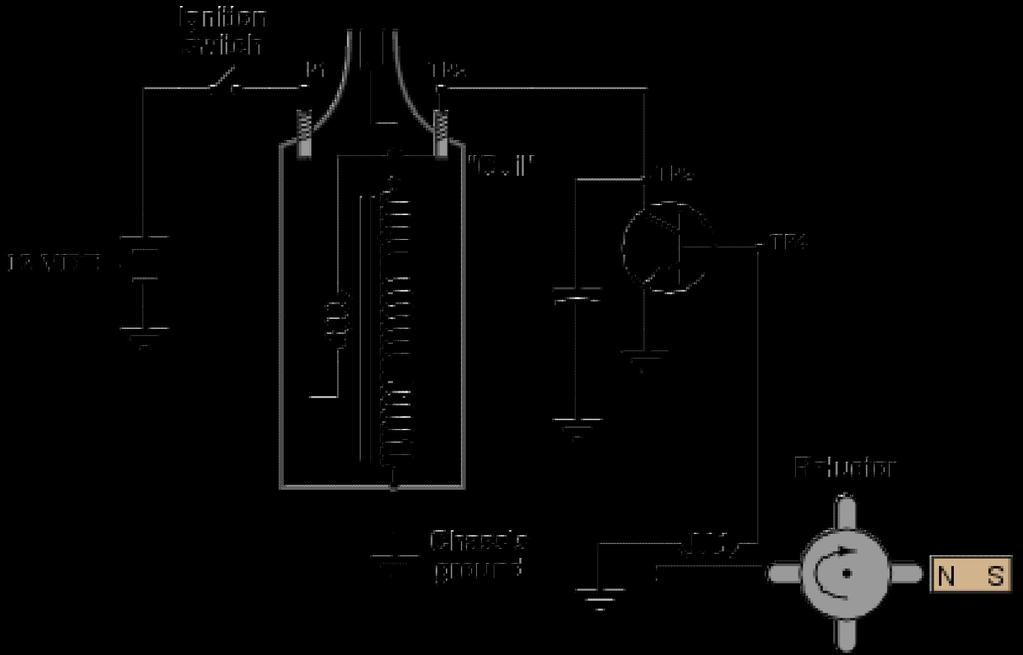
12 4. Battery current is switched on by the to supply the primary circuit. Injection Switch Ignition Switch Capacitor Switch


13 5. When the field in the primary ignition coil through the secondary ignition coil windings, a high voltage surge is generated (induced) & then sent to the plugs. Energetic, Collapses Magnetic, Collapses Magnetic, Relapses

14 6. Older ignition systems used a resistor or a calibrated resistance wire to act as a voltage drop in the primary circuit, limiting full charging voltage from reaching the primary coil. Ask about the Start & Run Circuits Ballast RFI Variable

15 7. The circuit carries the high voltage to the spark plugs. Base Primary Secondary

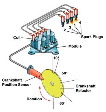
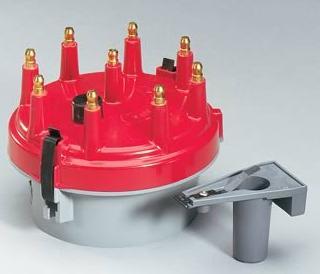
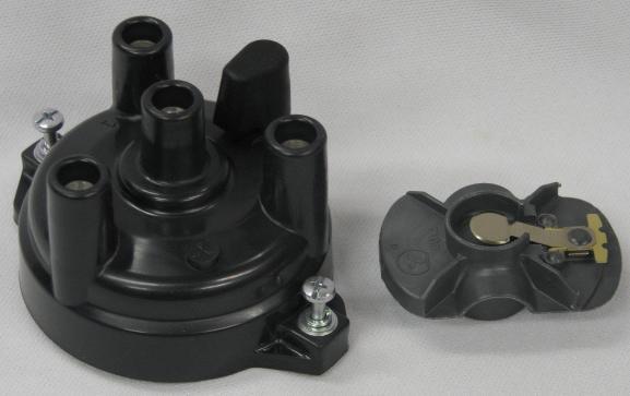
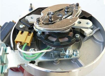
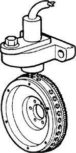
16 8. In a distributor system, the & deliver the sparks in the correct order. Cap & Rotor Cap & Reluctor Module & Rotor
17

18 9. EI systems, either wasted spark or direct, have firing current & spark duration. Higher, Longer Lower, Shorter Bigger, Faster
19 10. An ignition is a pulse that has two coils of wire wrapped around an iron core. Primary coil = turns of AWG 20 wire. Secondary = 15,000 20,000 turns of very fine wire. Coil, Transformer Coil, Reluctor Coil, Armature
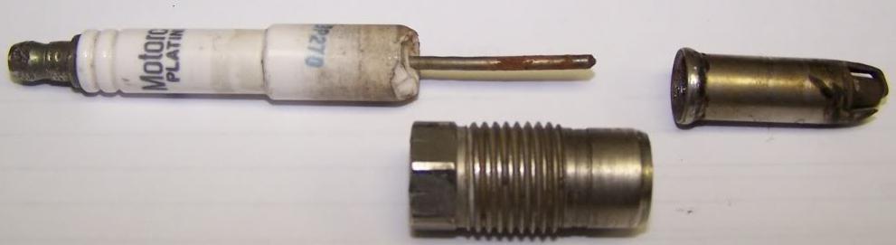
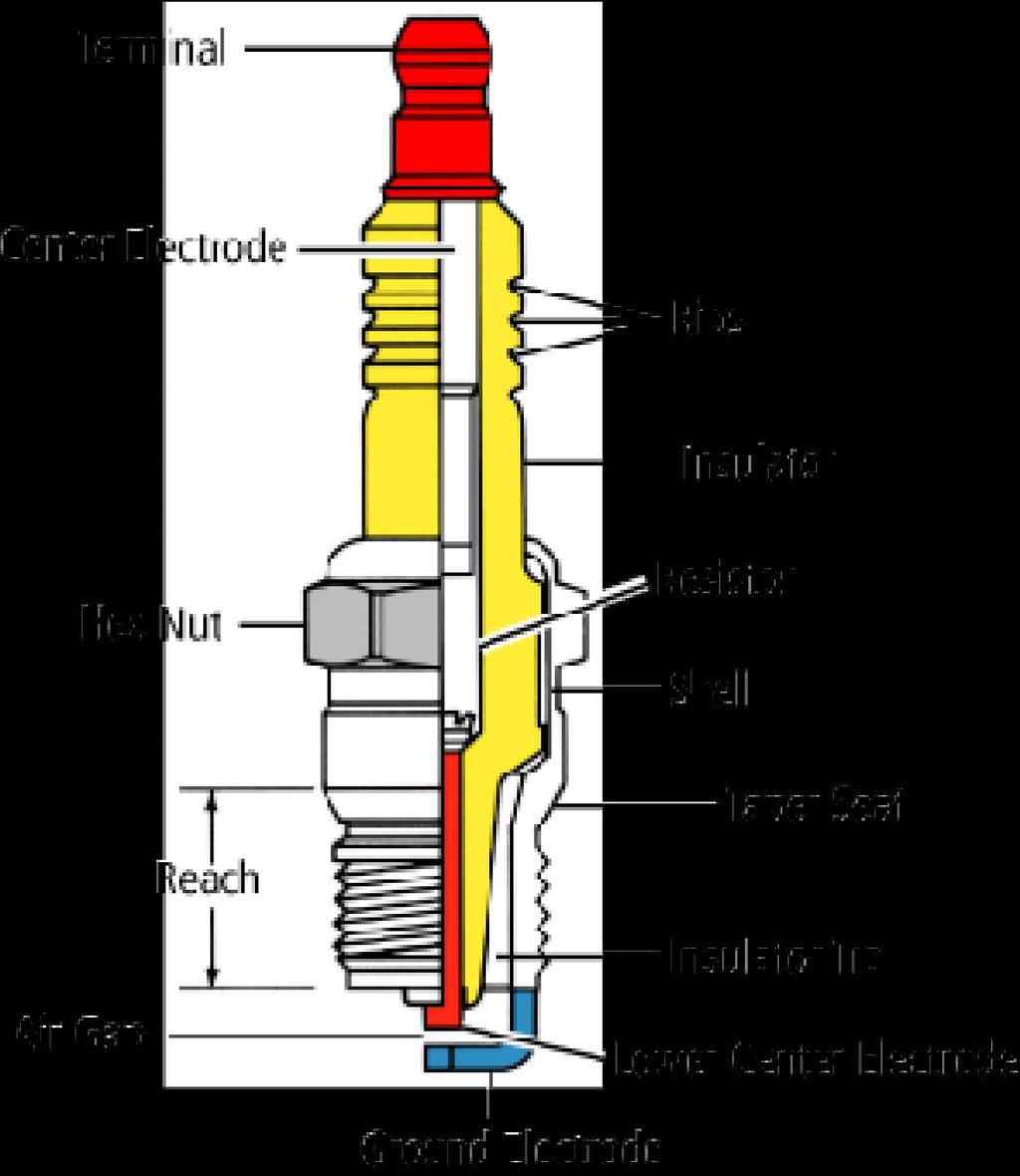
20 11. Iron or steel cores are used in ignition coils to reduce to magnetic lines of force. Resistance Reluctance Reactance
21

22 12. is the name given to the length of time the primary current flows in order to saturate the coil primary windings with magnetic fields. often now just called coil saturation time. Saturation Dwell Duration

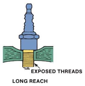
23 12. is the name given to the length of time the primary current flows in order to saturate the coil primary windings with magnetic fields. often now just called coil saturation time. Saturation Dwell Duration
24 13. is the term used to describe temporary resistance to current flow in the primary coil caused by magnetic field interference. This is the F in LSMFT (5 causes of resistance in a path). Resistance Reluctance Reactance

25 Resistance Reluctance Reactance


26 14. A coil with magnetism will have more potential to produce its designed voltage. Saturated Emulated Intimidated

27 15. Secondary coil windings are wound on the of the primary windings collapse inward. Inside Outside Middle


28 16. The difference between the voltage required to the plugs and the maximum voltage, is called secondary reserve voltage. This reserve is designed to prevent misfire under load. Fire, Output Fire, Input Fire, Battery


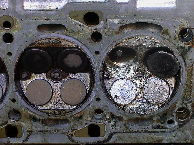
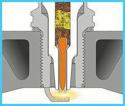
29 17. The spark plug is where high voltage causes the arc needed to ignite the A/F mix. Air Gap Air Rap Air Nap


30 18. on the insulator prevent electric arcing on the outside of the spark plug. Insulator Ribs Nibs Ribs Fibs

31 19. Spark plugs have either an mm or a 14 mm diameter thread sealed with either a steel washer or a tapered seat. Tightening specs differ depending upon the sealing method used. 1 mm 18 mm 25 mm


32 20. Thread (length) is crucial to properly position electrode gap in the combustion chamber. Reach Range Ranch
33


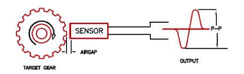
34 5.4 Liter Ford Triton V 8


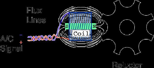
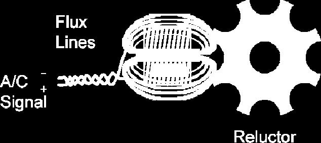
35 21. As heat range goes, a cold plug has a nose and a hot plug has a insulator nose.

36 Longer Path for Heat to Flow before being Cooled Shorter Path for Heat to Flow before being Cooled

37 22. type spark plugs have a 5kΩ internal resistor used to suppress RFI. Radio Frequency Interference = Static Noise Reluctor Resistor Reactor
38


39 23. The used in electrode construction determine a spark plug s longevity, power & efficiency. Electrode materials include copper nickel alloys, platinum, iridium, and yttrium. Materials Processes Designs


40 24. V groove, U groove & pin point designs require lower firing voltages. Electrode Thread Resistor
 plug wiring uses carbon")

41 25. Television & Radio Suppression (TVRS) plug wiring uses carbon impregnated cores without actual wire inside. This is done to lower RFI & EMI. Fiber Rope Steel
42 26. Electronic ignition systems switch the current on & off using an NPN transistor. The emitter is connected to ground, the collector to the coil negative terminal & the base is switched with a triggering device to interrupt (switch) the ground side of the primary coil. Primary Secondary Base

43 27. Sensors, like the CKP & CMP, are used to trigger the NPN. These sensors can be pulse generators, sensors, sensors & metal detection sensors. Magnetic, Hall Effect, Optical Reluctant, Hall Effect, Optical Reactant, Hall Effect, Optical


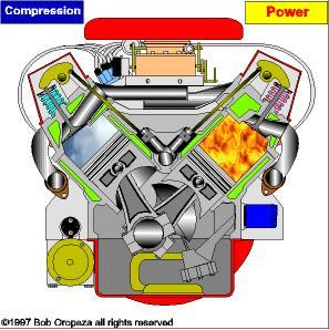
44 28. Magnetic pulse generators consist of a coil & a trigger wheel called a. These are also known as PM generators because they contain permanent magnets. Pick up, Reactor Pick up, Reluctor Pick up, Resistor

45 29. Metal detection sensors use pick up coils with instead of permanent magnets. Electromagnets Ribbon Magnets Horseshoe Magnets

46 30. The Hall effect sensor is the most popular type of engine position sensor due to its voltage signal throughout the entire engine rpm range and its ability to produce a square wave. Average Inaccurate Accurate


47 31. Photoelectric sensors use diodes and photo transistors as triggers. Light Absorbing Light Emitting Light Duty
48
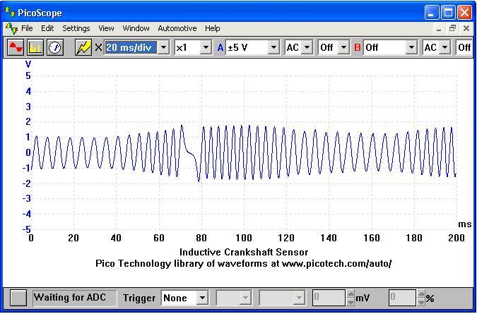
49 Note: Firing Order is the sequence in which the sparks occur that ignite the A/F mixture. (True Sparks or Event Sparks Only) shack.us/img153/18 3/mercedescorrecte dkk8.gif
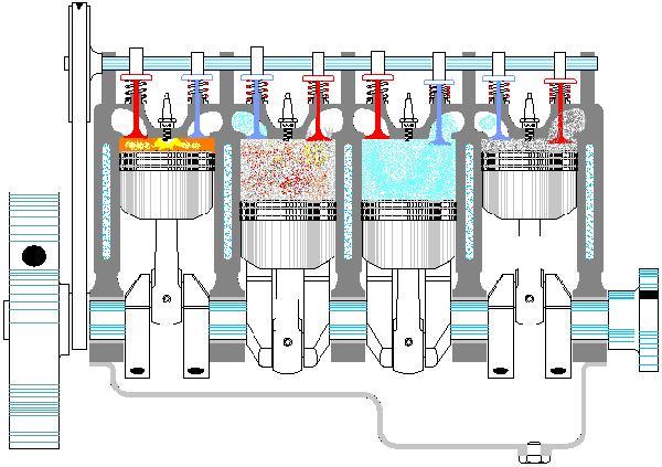
50 Be able to sketch the spark plug wiring for a 4 cylinder, in line engine with a distributorless ignition system and a firing order Note: Cylinder #1 and #4 are Companions Cylinder #2 and #3 are Companions
51 Sketch the spark plug wiring for a V 8 engine with a distributor in the rear of the engine, a clockwise rotation, a firing order, with cylinder #1 up front on the driver s side, odd # ed cylinders on the driver s side, & #1 plug wire located at 6 o clock on the distributor


52 32. Adjusting the the spark happens is critical to efficient engine operation. Way Time Method

53 33. Ignition timing is specified by relating the position of # piston to degrees of crank rotation. #1 #4 #8


54 34. Spark timing that is called 0 occurs at exactly at the end of the stroke. BDC, Compression TDC, Power TDC, compression
55
56
 CKP (speed) sensors as timing inputs.")
57 35. Both sensitive (vacuum) and sensitive (mechanical) devices have been used to change the timing of the spark. The PCM uses MAP (load) CKP (speed) sensors as timing inputs. Load, RPM Load, Speed Load, Torque
58 36. Distributors may contain an integral as well as an integral. Coil, Module Coil, Advance Coil, PCM


59 37. Distributorless (EI) systems are either spark or overcylinder designs. Wasted, Coil Wasted, Plug Wasted, Valve


60 38. EI systems eliminate parts that caused resistance & needed maintenance, reduced, increased time for saturation, allow individual control of cylinders, and operate cooler. Cost, Coil Misfire, Plug Cost, Fuel
, one coil is")

61 39. On spark (double ended coils), one coil is connected in series with two spark plugs. Wasted Direct True
62
 and 1 on exhaust stroke")
63 40. cylinders fire simultaneously, 1 on compression (event) and 1 on exhaust stroke (waste)
 can be")

64 41. Coil per cylinder ignition (direct) can be coil plug or coil plug. Coil on Plug Coil near Plug
65 42. On any and every ignition system design, timing at each cylinder can be individually changed for maximum performance. True or False


66 43. Some engines have 2 spark plugs per cylinder. True or False

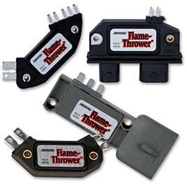
67 44. Some engines can fire multiple sparks from the same spark plug on one stroke. True or False HYFIRE VI IGNITION SYSTEM CD Multi Strike CD Ignition Features At A Glance: State of the art digital circuitry with 4 times faster processing. Boost proportional retard capability with optional harness. 2 stage rev limiting in 100 RPM increments. Automatic start retard circuit for easier starting. Built in RPM Window Switch which is great for nitrous oxide. Easy to use digital display with push button controls. Great for supercharged, turbocharged and nitrous applications. Primary Output Voltage: 525, Secondary Voltage Output: 45000, Spark Energy: 137mj.


68 45. Engine position sensors used for spark triggering can also be used to detect. Mileage Misfire Emissions
69 Crankshaft Toner Ring
70 46. Spark timing corrections are made to engines in an effort to compensate or correct or adapt for: coolant TEMPERATURE stabilizing engine IDLE TRANSITION correction engine KNOCK EGR operation TORQUE control TRACTION control correction
71
72 Now that we re through Keeping in mind that Career Clusters sensibly link education to careers Ask yourself: What careers could be linked to the topics in this slide series? Which of those careers might interest me? How do career clusters relate to my other high school classes? Do I need to change my 4 year plan to fit my desired career?
Ignition System Fundamentals
 Ignition System Fundamentals Chapter 37 Objectives Describe the functions of ignition system parts Explain the operation of points, electronic, and computer ignition systems Give an overview of the different
ATASA 5 th. ATASA 5 TH Study Guide Chapter 28 Pages Ignition Diagnosis & Service 62 Points. Please Read the Summary
 ATASA 5 TH Study Guide Chapter 28 Pages 836 873 62 Points Please Read the Summary Before We Begin Keeping in mind the Career Cluster of Transportation, Distribution & Logistics Ask yourself: What TDL careers
IGNITION SYSTEM COMPONENTS AND OPERATION
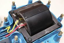
 69 IGNITION SYSTEM COMPONENTS AND OPERATION Figure 69-1 A point-type distributor from a hot rod being tested on a distributor machine. WARNING: The spark from an ignition coil is strong enough to cause
AUTOMOTIVE ENGINEERING SECTION
 PURPOSE OF IGNITION SYSTEM The ignition system supplies high-voltage surges as high as 47,000 volts (in some electronic systems) to the spark plugs in the engine cylinders. These surges produce electric
CHAPTER 6 IGNITION SYSTEM
 CHAPTER 6 CHAPTER 6 IGNITION SYSTEM CONTENTS PAGE Faraday s Law 02 The magneto System 04 Dynamo/Alternator System 06 Distributor 08 Electronic System 10 Spark Plugs 12 IGNITION SYSTEM Faraday s Law The
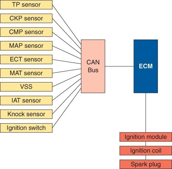
16.01 Theory Module INPUTS
 16.01 Theory Module INPUTS Crankshaft position sensor Camshaft position sensor Knock sensor (some engine types) Barometric pressure sensor Intake air temperature sensor Engine coolant temperature sensor
Fiero Ignition Systems. January 20, 2018 Rock Chevrolet Northern Illinois Fiero Enthusiasts Presented by Art Hall and Ray Dyreson
 Fiero Ignition Systems January 20, 2018 Rock Chevrolet Northern Illinois Fiero Enthusiasts Presented by Art Hall and Ray Dyreson 1 The Stock Fiero has Two Types of Ignition Systems Distributor 4 cyl: 84,
Chrysler Electronic Ignition System
 1 of 11 1/6/2010 11:02 PM Chrysler Electronic Ignition System Classic Winnebago's Post by: DaveVA78Chieftain on August 13, 2009, 10:15 PM Components The Chrysler Electronic Ignition System consists of
1.0 Installation Wiring
 1.0 Installation Wiring DX Firebox is designed to be an electronic replacement for Pontiac & Ford buzz coils when operated on DC. Installation may be positive or negative ground. Simply observe the RED
MAX-FIRE AND E-FIRE ELECTRONIC DISTRIBUTORS
 INSTALLATION INSTRUCTIONS MAX-FIRE AND E-FIRE ELECTRONIC DISTRIBUTORS NOTE: This product is applicable to pre-1966 California and pre-1968 federally certified passenger cars. It is also applicable to non-emission
Sensors & Controls. Everything you wanted to know about gas engine ignition technology but were too afraid to ask.
 Everything you wanted to know about gas engine ignition technology but were too afraid to ask. Contents 1. Introducing Electronic Ignition 2. Inductive Ignition 3. Capacitor Discharge Ignition 4. CDI vs
IGNITION SYSTEM 8D - 1 IGNITION SYSTEM TABLE OF CONTENTS
 LH IGNITION SYSTEM 8D - 1 IGNITION SYSTEM TABLE OF CONTENTS page AND IGNITION SYSTEM...1 SPARK PLUGS-PLATINUM....1 COIL ON PLUG...1 CRANKSHAFT POSITION SENSOR....2 CAMSHAFT POSITION SENSOR....3 KNOCK SENSOR....5
Asynchronous Restriking CDI 2 channel
 Asynchronous Restriking CDI 2 channel Parts List ARC-2 module Decals Power Cable Fuse Specifications Operating Voltage: 8-20V Operating Current: Max Operating RPM: Ambient Temp range: Ignition inputs:
Contents. DX Ignition Page 2
 Contents 1.0 Intent 2.0 Specifications 3.0 Installation 4.0 Operation Precautions 5.0 Repair 6.0 Parts List 7.0 Glossary of Terms 8.0 Contact Information DX Ignition Page 2 1.0 Intent The purpose of this
Motronic September 1998
 The Motronic 1.8 engine management system was introduced with the 1992 Volvo 960. The primary difference between this Motronic system and the previous generation of Volvo LH-Jetronic engine management
E - THEORY/OPERATION - TURBO
 E - THEORY/OPERATION - TURBO 1995 Volvo 850 1995 ENGINE PERFORMANCE Volvo - Theory & Operation 850 - Turbo INTRODUCTION This article covers basic description and operation of engine performance-related
Chapter 4 Ignition & Electrical Systems
 Chapter 4 Ignition & Electrical Systems Chapter 4 Section A Study Aid Questions Fill in the Blanks 1. Ignition systems can be divided into two classifications: systems or systems for reciprocating engines.
Name Date. True-False. Multiple Choice
 Name Date True-False T F 1. Oil film thickness increases with an increase in oil temperature. T F 2. Displacement is the volume that a piston displaces in an engine when it travels from top dead center
Ladies and Gentlemen... We Have Ignition!
 FEATURE Ladies and Gentlemen... We Have Ignition! The coordination of ignition, fuel delivery and basic engine function is required before internal combustion can take place. Here, we'll look at the ignition
ASE 8 - Engine Performance. Module 9 Ignition Systems
 ASE 8 - Engine Module 9 Acknowledgements General Motors, the IAGMASEP Association Board of Directors, and Raytheon Professional Services, GM's training partner for GM's Service Technical College wish to
UNIT 4 IGNITION SYSTEMS
 UNIT 4 IGNITION SYSTEMS Ignition Systems Structure 4.1 Introduction Objectives 4.2 Ignition System Types 4.3 Comparison between Battery and Magneto Ignition System 4.4 Drawbacks (Disadvantages) of Conventional
INSTALLATION INSTRUCTIONS
 INSTALLATION INSTRUCTIONS FRM34418 (REV. B) 09/17 UNILITE DISTRIBUTOR This product is applicabl e to pre-1966 California and pre-1968 federally certified passenger cars. It is also applicable to non-emission
The PCM is the on-board computer which receives input from various sensors and, with this information, controls various engine & emissions control
 The PCM is the on-board computer which receives input from various sensors and, with this information, controls various engine & emissions control actuators. The PCM has various memories within it. These
Error codes Diagnostic plug Read-out Reset Signal Error codes
 Error codes Diagnostic plug Diagnostic plug: 1 = Datalink LED tester (FEN) 3 = activation error codes (TEN) 4 = positive battery terminal (+B) 5 = ground Read-out -Connect LED tester to positive battery
WEAPONX CIRCUIT COMPRESSION
 WeaponX Ignition Coil Technology WeaponX designs and employs the greatest performance proven technologies available. The creation of a high quality ignition system has been a challenging process for OEMS
4.0L CEC SYSTEM Jeep Cherokee DESCRIPTION OPERATION FUEL CONTROL DATA SENSORS & SWITCHES
 4.0L CEC SYSTEM 1988 Jeep Cherokee 1988 COMPUTERIZED ENGINE Controls ENGINE CONTROL SYSTEM JEEP 4.0L MPFI 6-CYLINDER Cherokee, Comanche & Wagoneer DESCRIPTION The 4.0L engine control system controls engine
Technology with Vision. SPARK PLUGS Unleash the POWER. South Africa Sub-Sahara Region
 Technology with Vision SPARK PLUGS Unleash the POWER South Africa Sub-Sahara Region 2 HELLA KGaA Hueck & Co. Unleash the POWER About HELLA HELLA KGaA Hueck & Co. is a globally positioned company at more
5. Control System CONTROL SYSTEM FUEL INJECTION (FUEL SYSTEM) A: GENERAL. FU(STi)-27
 A: GENERAL. FU(STi)-27") W1860BE.book Page 27 Tuesday, January 28, 2003 11:01 PM 5. Control System A: GENERAL The ECM receives signals from various sensors, switches, and other control modules. Using these signals, it determines
W1860BE.book Page 27 Tuesday, January 28, 2003 11:01 PM 5. Control System A: GENERAL The ECM receives signals from various sensors, switches, and other control modules. Using these signals, it determines
Ignition control. The ignition system tasks. How is the ignition coil charge time and the ignition setting regulated?
 1 Ignition control The ignition system tasks To transform the system voltage (approximately 14 V) to a sufficiently high ignition voltage. In electronic systems this is normally above 30 kv (30 000 V).
Battery powered ignition
 Battery powered ignition A typical battery powered ignition uses a transformer, a several switching devices, and a power source. The power source is the battery. Battery powered ignition The first switch
CPi. CoiL PACK IGNiTioN FOR AViATiON. For 4,6 and 8 cylinder 4 stroke applications. Please read the entire manual before beginning installation.
 1 CPi CoiL PACK IGNiTioN FOR AViATiON Coil pack (4 cylinder) Coil pack (6 cylinder) For 4,6 and 8 cylinder 4 stroke applications. Please read the entire manual before beginning installation. Software version
IGNITION SYSTEM IGNITION SYSTEM
 IGNITION SYSTEM IGNITION SYSTEM opyright Gautam Malik 2007 IGNITION SYSTEM opyright Gautam Malik 2007 IGNITION FUNTION Produces 15000-30,000 volt spark across spark plug Distributes high voltage spark
AUTRONIC SM3 ECU Specifications
 AUTRONIC SM3 ECU Specifications Microcomputer Power Supply - Voltage Normal operation Operational limits Intel 16 bit 20MHz 12v to 15v DC 6.2v to 18v DC continuous Power Supply - Current Survival limits
HYFIRE 6.6 SERIES OF ELECTRONIC IGNITION CONTROL
 FORM 1486M 03/05 INSTALLATION INSTRUCTIONS HYFIRE 6.6 SERIES OF ELECTRONIC IGNITION CONTROL HYFIRE 6.6 IGNITION SYSTEM PART NO. 686M FOR APPLICATIONS TRIGGERED BY POINTS, MALLORY ELECTRONIC IGNITION DISTRIBUTOR
Charging Systems. ATASA 5 th. ATASA 5 TH Study Guide Chapter 19 Pages Charging Systems 42 Points. Please Read The Summary
 ATASA 5 TH Study Guide Chapter 19 Pages 571 595 42 Points Please Read The Summary 1. The primary purpose of the charging system is to the battery with a constant and relatively low charge after it has
AUTOMOTIVE TECHNOLOGY Electricity and Electronics
 AUTOMOTIVE TECHNOLOGY Electricity and Electronics Al Santini Retired, College of DuPage Glen Ellyn, Illinois Jack Erjavec, Series Editor Professor Emeritus, Columbus State Community College Columbus, Ohio
5. Control System CONTROL SYSTEM FUEL INJECTION (FUEL SYSTEM) A: GENERAL FU(H4DOTC)-29
 A: GENERAL FU(H4DOTC)-29") W1860BE.book Page 29 Tuesday, January 28, 2003 11:01 PM 5. Control System A: GENERAL The ECM receives signals from various sensors, switches, and other control modules. Using these signals, it determines
W1860BE.book Page 29 Tuesday, January 28, 2003 11:01 PM 5. Control System A: GENERAL The ECM receives signals from various sensors, switches, and other control modules. Using these signals, it determines
Module 22 Ignition Systems - Outputs
 Module 22 Ignition Systems - Outputs Author: Grant Swaim E-mail: sureseal@nr.infi.net URL: www.tech2tech.net Phone: (336) 632-9882 Fax: (336) 632-9688 Postal Address: Tech-2-Tech Website PO Box 18443 Greensboro,
POLESTAR HS Management System
 POLESTAR HS Management System Installation Instructions This document contains the information needed to install and adjust the POLESTAR HS Engine Management System. It assumes that the system already
2014 Hyundai Veloster ENGINE Ignition System - Veloster Turbo. Ignition System - Veloster Turbo
 DESCRIPTION AND OPERATION DESCRIPTION 2013-14 ENGINE Ignition System - Veloster Turbo Ignition timing is controlled by the electronic control ignition timing system. The standard reference ignition timing
CAUTION: READ INSTRUCTIONS CAREFULLY BEFORE STARTING INSTALLATION
 V-Twin MFG. VT No. 32-9500 V-TECH 1 IGNITION KIT, SINGLE FIRE FITS EV SHOVEL, XL THRU 1997 VT No. 32-9503 V-TECH 1 IGNITION KIT, SINGLE FIRE FITS EV, SHOVEL, XL, WITH COIL AND WIRES This is a custom application
75 SERIES BILLET HEI DISTRIBUTORS
 INSTALLATION INSTRUCTIONS 75 SERIES BILLET HEI DISTRIBUTORS GENERAL INFORMATION Mallory 75 Series Distributors are similar to GM HEI distributors, but with many advantages over the OEM design, including:
ASE 8 - Engine Performance. Module 8 Ignition Systems Triggering
 Module 8 Ignition Acknowledgements General Motors, the IAGMASEP Association Board of Directors, and Raytheon Professional Services, GM's training partner for GM's Service Technical College wish to thank
IGNITION SYSTEM GENERAL. Crankshaft Position Sensor (CPS) Magneto System. Section 12 ELECTRICAL SYSTEM Subsection 01 (IGNITION SYSTEM)
 Magneto System. Section 12 ELECTRICAL SYSTEM Subsection 01 (IGNITION SYSTEM)") IGNITION SYSTEM GENERAL NOTE: For DI and 4-TEC models, refer to ENGINE MANAGEMENT section. ENGINE TYPE MAGNETO OUTPUT WATT 77 60 @ 6000 RPM 787 RFI 70 @ 6000 RPM Unregulated AC current is produced in the
IGNITION SYSTEM GENERAL NOTE: For DI and 4-TEC models, refer to ENGINE MANAGEMENT section. ENGINE TYPE MAGNETO OUTPUT WATT 77 60 @ 6000 RPM 787 RFI 70 @ 6000 RPM Unregulated AC current is produced in the
Tri-Spark Ignition System Installation Triple Cylinder TRI-0001
 Tri-Spark Ignition System Installation Triple Cylinder TRI-0001 There are potentially lethal high voltages produced at the ignition coils and spark plugs, therefore every precaution must be taken to prevent
Manual - FTSPARK v3 - Capas ENUS.pdf 1 2/16/2017 6:06:34 PM C M Y CM MY CY CMY K OWNER S MANUAL
 OWNER S MANUAL Index 1. Presentation...4 2. Characteristics...5 3. Warranty terms...6 4. Installation...7 4.1 Mounting...7 4.2 Power supply...7 4.3 Harness connections table...8 4.4 Wiring harness installation...
Installation Instructions for Lingenfelter Shift Light Controller with green LED
 Installation Instructions for Lingenfelter Shift Light Controller with green LED PN: L460080000 1557 Winchester Road Decatur, Indiana 46733 260 724 2552 phone 260 724 8761 fax www.lingenfelter.com Parts
INSTALLATION INSTRUCTIONS for. FC 2000 Series
 INSTALLATION INSTRUCTIONS for Fire Control (FC) Ignition System FC 2000 Series Owners Manual Introduction...2 Specifications...2 Coil Compatibilities...2 Wire Functions...2 Connections...3-6 Connections
ATASA 5 th. ABS & Traction Control Systems. Please Read The Summary
 ATASA 5 TH Study Guide Chapter 51 Pages: 1506 1534 Antilock Brake Systems 59 Points Please Read The Summary Before We Begin Keeping in mind the Career Cluster of Transportation, Distribution & Logistics
IGNITION SYSTEM 8D - 1 IGNITION SYSTEM CONTENTS
 ZJ IGNITION SYSTEM 8D - 1 IGNITION SYSTEM CONTENTS page GENERAL INFORMATION INTRODUCTION... 2 DESCRIPTION AND OPERATION AUTOMATIC SHUTDOWN (ASD) RELAY... 3 CAMSHAFT POSITION SENSOR... 4 CRANKSHAFT POSITION
Focus on Training Section: Unit 2
 All Pump Types Page 1 1. Title Page Learning objectives Become familiar with the 4 stroke cycle Become familiar with diesel combustion process To understand how timing affects emissions To understand the
ELECTRONIC ENGINE CONTROLS
 2005 Jaguar S-Type (X200) V8-4.2L Vehicle > Powertrain Management > Computers and Control Systems > Description and Operation > Components ELECTRONIC ENGINE CONTROLS Electronic Engine Controls Vehicles
NGK Guide to Spark Plugs
 Spark plug gap Always check that the spark plug gap is compatible with the engine manufacturer s specification. A gap that is too small means that the spark duration will be very quick and the spark will
FUEL INJECTION SYSTEM - MULTI-POINT
 FUEL INJECTION SYSTEM - MULTI-POINT 1988 Jeep Cherokee 1988 Electronic Fuel Injection JEEP MULTI-POINT 4.0L Cherokee, Comanche, Wagoneer DESCRIPTION The Multi-Point Electronic Fuel Injection (EFI) system
Champion Spark Plugs for Proven Performance. Three Steps To Selecting a High Performance Plug
 Page 1 of 7 Champion Spark Plugs for Proven Performance Edelbrock has joined with Champion to bring you the correct and best performing spark plugs for your application. These plugs add to our Total Power
Motronic ignition system, servicing
 Page 1 of 25 28-2 Motronic ignition system, servicing Note: Motronic Engine Control Module (ECM) J220* with connector page 24-9, item 16. 1 - Highvoltage ignition cable Ignition secondary circuit Check
 Solid State Ignition Replacement May 15, 2005 Introduction: There are two Tecumseh Solid State Ignitions ( SSI ) configurations we are concerned with here: The one on the left I call SSI Under for short
The Physics of the Automotive Ignition System
 I. Introduction This laboratory exercise explores the physics of automotive ignition systems used on vehicles for about half a century until the 1980 s, and introduces more modern transistorized systems.
MFI Pro - Instructional Manual (Toyota 1uzfe) Version 06.01
 Version 06.01") Tel: 011 3971953 - Fax: 011 3978197 - info@gotech.co.za www.got e ch.c o.za MFI Pro - Instructional Manual (Toyota 1uzfe) Version 06.01 Index: Introduction 1 Before You Begin 1 Basic Tools Required 2 Basic
Tel: 011 3971953 - Fax: 011 3978197 - info@gotech.co.za www.got e ch.c o.za MFI Pro - Instructional Manual (Toyota 1uzfe) Version 06.01 Index: Introduction 1 Before You Begin 1 Basic Tools Required 2 Basic
IGNITION SYSTEMS DESCRIPTION EARLY INDUCTION TYPE
 IGNITION SYSTEMS Turbine engine ignition systems fall into two general classifications. The induction type produces high-tension sparks by conventional induction coils. The capacitor type causes ignition
G - TESTS W/CODES - 2.2L
 G - TESTS W/CODES - 2.2L 1994 Toyota Celica 1994 ENGINE PERFORMANCE Toyota 2.2L Self-Diagnostics Celica INTRODUCTION If no faults were found while performing F - BASIC TESTING, proceed with self-diagnostics.
1. Replace the plugs with the cheap Autolite (25) copper-core plugs, set to 80 thou gap.
 copper-core plugs, set to 80 thou gap.") A recently encountered e-mail from Robert Calloway states that Tesla s bi-filar series-connected coil is effective in picking up radiant energy. In the light of that, and in the absence of further information
A recently encountered e-mail from Robert Calloway states that Tesla s bi-filar series-connected coil is effective in picking up radiant energy. In the light of that, and in the absence of further information
Installation Instructions
 Installation Instructions 8 Channel C 2 D Ignition System PN 30-2800 4 Channel C 2 D Ignition System PN 30-2801 WARNING: This installation is not for the electrically challenged! Use this ignition with
Air Cooled Engine Technology. Roth 9 th Ch 5 2 & 4 Cycle Engines Pages 81 94
 Roth 9 th Ch 5 2 & 4 Cycle Engines Pages 81 94 1. The of the piston is its movement in the cylinder from one end of its travel to another. Either TDC to BDC (downstroke) or BDC to TDC (upstroke). Identified
HYFIRE VI SERIES OF ELECTRONIC IGNITION CONTROLS HYFIRE VI Ignition System Part No. 685, Advanced HYFIRE VI Ignition System Part No.
 FORM 1478 (REV. D) 09/2008 INSTALLATION INSTRUCTIONS HYFIRE VI SERIES OF ELECTRONIC IGNITION CONTROLS HYFIRE VI Ignition System Part No. 685, Advanced HYFIRE VI Ignition System Part No. 6851, Basic For
Spark Plug Valve Spring Mixture In. Cylinder Head. Intake Valve. Cooling Water. Piston. Crankcase
 Simply put, an ignition system activates a fuel-air mixture to create energy. The first ignition system to use an electric spark is thought to be Alessandro Volta s toy electric pistol, ca. 1780. We ve
OMEM200 Tuning Manual 3v Series ECU. Tuning Manual OMEM200.
 200 Series ECU Tuning Manual OMEM200 www.omextechnology.com 0 1 Introduction... 3 1.1 What this manual covers... 3 1.2 Notation Used in This Manual... 3 2 Software... 4 3 Sensor Setup... 5 3.1 Throttle
Fire in the Hole. Choosing a set of racing spark. Racing Spark Plugs. By Larry Carley, Technical Editor
 Fire in the Hole Racing By Larry Carley, Technical Editor lcarley@babcox.com Choosing a set of racing spark plugs for a particular application is not as easy as it sounds because the plugs have to be closely
Ignition Why You Need A Spark
 Simply put, an ignition system activates a fuel-air mixture to create energy. The first ignition system to use an electric spark is thought to be Alessandro Volta s toy electric pistol, ca. 1780. We ve
MSD 7AL-2 Plus Ignition PN 7222
 MSD 7AL-2 Plus Ignition PN 7222 Note: Solid Core spark plug wires cannot be used with an MSD Ignition. Note: An MSD cannot be used on vehicles with CD ignitions or distributorless ignition systems. Parts
THE FOURTH STATE. Gaining a universal insight into the diagnosis of automotive ignition systems. By: Bernie Thompson
 THE FOURTH STATE Gaining a universal insight into the diagnosis of automotive ignition systems By: Bernie Thompson Did you know that the forth state of matter powers the spark ignition internal combustion
ACCEL Distributor Model #A557
 FORM 1627 REV1 INSTALLATION INSTRUCTIONS ACCEL Distributor Model #A557 CAUTION: CAREFULLY READ INSTRUCTIONS BEFORE PROCEEDING. NOT LEGAL FOR USE OR SALE ON POLLUTION CONTROLLED VECHICLES OVERVIEW ACCEL
Electronics III Sensors
 Electronics III Sensors Matthew Whitten Brookhaven College Sensor Defined. A device that responds to a stimulus, such as heat, light, or pressure, and generates a signal that can be measured or interpreted.
MSD Stacker-4 (4-Channel), PN 7010 Stacker-8 (8-Channel), PN 7020
, PN 7010 Stacker-8 (8-Channel), PN 7020") INSTALLATION INSTRUCTIONS 1 MSD Stacker-4 (4-Channel), PN 7010 Stacker-8 (8-Channel), PN 7020 Important: Read these instructions before attempting this installation! Parts Included: 1 - MSD Stacker Ignition
INSTALLATION INSTRUCTIONS 1 MSD Stacker-4 (4-Channel), PN 7010 Stacker-8 (8-Channel), PN 7020 Important: Read these instructions before attempting this installation! Parts Included: 1 - MSD Stacker Ignition
MSD Digital 6M-3L Marine Ignition PN 6564
 MSD Digital 6M-3L Marine Ignition PN 6564 ONLINE PRODUCT REGISTRATION: Register your MSD product online. Registering your product will help if there is ever a warranty issue with your product and helps
HYFIRE VII Series Electronic Ignition Controls Instruction Manual Part#: 667C
 HYFIRE VII Series Electronic Ignition ontrols Instruction Manual Part#: 667 FORM 1460 (REV. ) 5/00 INSTALLATION INSTRUTIONS HYFIRE VII PRO D IGNITION SYSTEM Part No. 667 4-12 ylinder 6 ylinder Odd-Fire
Small engine EFI conversion kits VRS technical spec VRS SENSOR. Technical Spec ECOTRONS LLC COPY RIGHTS ECOTRONS ALL RIGHTS RESERVED
 VRS SENSOR Technical Spec ECOTRONS LLC COPY RIGHTS ECOTRONS ALL RIGHTS RESERVED Note: If you are not sure about any specific details, please contact us at info@ecotrons.com. Copy rights ECOTRONS LLC 1
PERTRONIX DIGITAL HP INSTALLATION INSTRUCTIONS
 PERTRONIX DIGITAL HP INSTALLATION INSTRUCTIONS TABLE OF CONTENTS Specifications... 4 General Information... 5 Coil Compatibility... 6 Mounting the Digital HP... 7 Wiring... 8 User Interface... 12 Programming...
STREET/RACE DISTRIBUTOR
 Installation Instructions for STREET/RACE DISTRIBUTOR CAUTION: READ INSTRUCTIONS CAREFULLY BEFORE STARTING INSTALLATION INTRODUCTION The Crane Cams street/race distributor is a high precision system intended
INSTALLATION INSTRUCTIONS for HI-4 DUAL FIRE MOTORCYCLE IGNITION. Part Number INTRODUCTION REMOVAL OF POINTS IGNITION TO 1977 MODELS
 INSTALLATION INSTRUCTIONS for HI- DUAL FIRE MOTORCYCLE IGNITION Part Number -00 CAUTION: READ INSTRUCTIONS CAREFULLY BEFORE STARTING INSTALLATION INTRODUCTION The HI- ignition system is intended for use
04. Ignition and Exhaust system
 New Polytechnic Kolhapur Page 1 of 10 04. Ignition and Exhaust system 4.1 Introduction to Ignition System 4 Marks Requirements of ignition system. Magneto and Battery Ignition systems (Working only). Firing
HI-6 CD IGNITION With Rev Limiter and Timing Retard
 Installation Instructions for CD With Rev Limiter and Timing Retard For more information, see www.cranecams.com CAUTION: READ INSTRUCTIONS CAREFULLY BEFORE STARTING INSTALLATION. READ THIS BEFORE YOU BEGIN!
Quality Management After-Sales. WORKSHOP MANUAL ECU-CONTROLLED CARBURETION SYSTEM EURO 4 DELL'ORTO
 Quality Management After-Sales. WORKSHOP MANUAL - ECU-CONTROLLED CARBURETION SYSTEM EURO 4 DELL'ORTO TABLE OF CONTENTS TABLE OF CONTENTS SYNOPTICS... 3 GENERAL VIEW... 4 DETAILED DESCRIPTION OF COMPONENTS...
Mounting instructions for the '123ignition'
 Mounting instructions for the '123ignition' type : 123\GB-4-R-V for : most English 4 cylinder engines, 6 & 12 Volt, negative earth only! IMPORTANT Please read the entire instructions before you begin installation.
DISASSEMBLY Procedure revision date: 11/22/2001
 Page 1 of 31 Evan Groenke From: Daniel Lelovic [dlelovic@rogers.com] Sent: May 8, 2005 12:06 PM To: 'Evan Groenke' Subject: 2.5 L Engine Disassembly SECTION 303-01B: Engine 2.5L 2000 Contour/Mystique Workshop
Mallory HyFire Electronic Ignition Control
 Mallory HyFire Electronic Ignition Control PN 690 Parts Included: 1 - Ignition 1 - Harness, Mag Pickup 1-18" Ground Wire 1-100V/1A Diode 4 - Mounting Screws WARNING: During installation, disconnect the
Electronics III Sensors
 Electronics III Sensors Matthew Whitten Brookhaven College Sensor Defined. A device that responds to a stimulus, such as heat, light, or pressure, and generates a signal that can be measured or interpreted.
1. What type of material can be induced to become a temporary magnet? A) diamagnetic B) ferromagnetic C) monomagnetic D) paramagnetic
 diamagnetic B) ferromagnetic C) monomagnetic D) paramagnetic") Assignment 1 Magnetism and Electromagnetism Name: Multiple Choice Identify the letter of the choice that best completes the statement or answers the question. Show appropriate workings. 1. What type of
Assignment 1 Magnetism and Electromagnetism Name: Multiple Choice Identify the letter of the choice that best completes the statement or answers the question. Show appropriate workings. 1. What type of
4. Sensors and Switches
 FUEL INJECTION (FUEL SYSTEM) SENSORS AND SWITCHES 4. Sensors and Switches A: FRONT OXYGEN (A/F) SENSOR The front oxygen sensor uses zirconium oxide (ZrO 2 ) which is a solid electrolyte, at portions exposed
SECTION C Engine 5.4L (4V)
") 303-01C-i Engine 5.4L (4V) 303-01C-i SECTION 303-01C Engine 5.4L (4V) CONTENTS PAGE SPECIFICATIONS... 303-01C-2 303-01C-2 Engine 5.4L (4V) 303-01C-2 SPECIFICATIONS Material Motorcraft Metal Surface Prep
303-01C-i Engine 5.4L (4V) 303-01C-i SECTION 303-01C Engine 5.4L (4V) CONTENTS PAGE SPECIFICATIONS... 303-01C-2 303-01C-2 Engine 5.4L (4V) 303-01C-2 SPECIFICATIONS Material Motorcraft Metal Surface Prep
SCHNITZ MOTORSPORTS USER MANUAL AND INSTALLATION GUIDE PRO-MOD BATTERY VOLTS DIAGNOSTICS NOS PULSE FREQUENCY NOS DELAY TIME IN SECONDS
 SCHNITZ MOTORSPORTS DSC-CS "PRO-MOD" IGNITION CONTROLLER USER MANUAL AND INSTALLATION GUIDE COIL, (OPTIONAL) GA YELLOW, COIL, NEGATIVE GA WHITE, GA BLACK, SHIFT LIGHT +V OUTPUT PAGE 0 NOS ACTIVATION INPUT
DTC P0351, P0352, P0353, P0354, P0355, P0356, P0357, or P0358
 DTC Descriptor DTC P0351 Ignition coil 1 control circuit DTC P0352 Ignition coil 2 control circuit DTC P0353 Ignition coil 3 control circuit DTC P0354 Ignition coil 4 control circuit DTC P0355 Ignition
Installation Guide for the Electronic Ignition Distributor
 Installation Guide for the Electronic Ignition Distributor Remanufactured By East Coast Roadster East Coast Roadster: Ignition systems and accessories for Datsun Roadster fanatics! PLEASE, Call with any
SECTION 2.10 IGNITION SYSTEM DESCRIPTION CEC IGNITION MODULE SYSTEM MAGNETO IGNITION SYSTEM
 SECTION 2.10 SYSTEM DESCRIPTION CEC SYSTEM The Custom Engine Control (CEC) Ignition Module is located on the engine's left side (see Figure 2.10-1 and Figure 2.10-2). The CEC Ignition Module system consists
Fig.11 Powertrain Control Module (PCM)
") 2003 Dodge or Ram Truck Caravan V6-3.3L VIN R Vehicle > Powertrain Management > Relays and Modules - Powertrain Management > Relays and Modules - Computers and Control Systems > Engine Control Module >
2003 Dodge or Ram Truck Caravan V6-3.3L VIN R Vehicle > Powertrain Management > Relays and Modules - Powertrain Management > Relays and Modules - Computers and Control Systems > Engine Control Module >
Crank Trigger Hardware Installation
 Crank Trigger Hardware Installation Step 1 - Bring the engine up to TDC and remove the crank pulley bolt. Step 2 - Install trigger wheel making sure to line up the keyway. You may need to use the bolt
Internal Combustion Engines
 Internal Combustion Engines The internal combustion engine is an engine in which the burning of a fuel occurs in a confined space called a combustion chamber. This exothermic reaction of a fuel with an
FUELMISER PRODUCT RANGE
 FUELMISER PRODUCT RANGE The broadest from world leading WE KNOW HOW IMPORTANT IT IS TO KNOW THAT OUR HIGH QUALITY PRODUCTS ARE MADE BY LEADING OEM & OES MANUFACTURERS. That s why Fuelmiser products are
MSD Digital SCI+ Ignition Control, PN 6350
 MSD Digital SCI Ignition Control, PN 6350 Parts Included: 1 - MSD Ignition 1 - Harness, PN 8860 1 - Parts Bag, ASY19864 WARNING: During installation, disconnect the battery cables. When disconnecting the
Contents. Preface... xiii Introduction... xv. Chapter 1: The Systems Approach to Control and Instrumentation... 1
 Contents Preface... xiii Introduction... xv Chapter 1: The Systems Approach to Control and Instrumentation... 1 Chapter Overview...1 Concept of a System...2 Block Diagram Representation of a System...3