Ural (Урал) - Dnepr (Днепр) Russian Motorcycle Carburetors. Ernie Franke 05/2011
|
|
|
- Jessie Hudson
- 6 years ago
- Views:
Transcription

1 Ural (Урал) - Dnepr (Днепр) Russian Motorcycle Carburetors Part 2: K-37 K and K-37AK Ernie Franke eafranke@tampabay.rr.com 05/2011


2 K-37 and K-37A K Carburetor Used in Dnepr M-72, MB-750 and K cc Engines Later Replaced by K-38 and K-301 Motorcycle has Two Carburetors Right and Left-Side Version Similar, but Mirror-Images Specifications: Diameter of Inlet Pipe: 24 mm Diameter of Mixing Chamber: 24 mm Distance from Fuel Level in Float Chamber to Plane of Connector: 21 mm Weight of Float: 8.5 g Carburetor Weight: 0.85 kg Capacity of Main Jet: 160 cm 3 /min Capacity of Main Jet: 21 cm 3 /min K-38 carbs were used on the M-72, K-750 and MB-750, until replaced by the K-38 carburetor.
 K-37A (M-72, M-72K, M-72M, M-72H,")
 K-301В (MT-10) K-301Г")
 K-37 K-37A K-38")
 CVK32 Keihin (8.")
 K-302 K-62 K-63/K-65 K-68 1975 K-302")
 K-62 (MT-16, MT-12, MB-650) 28 mm Mikuni")


3 Russian Carburetor Time-Line (03/2011) K-37 (M-72) K-37A (M-72, M-72K, M-72M, M-72H, K-750, MB-750) K-38 (M-61, M-62, M-63) K-301Б (M-63, M-66, K-650/MT-9) K-301В (MT-10) K-301Г (M-63, M-67, M-67.36) K-301Д (MT-10, MT-10.36, MB-650M, K-650/MT-8/MT-9) K-37 K-37A K-38 K K-63/K-65 (MT-11, MT-16) CVK32 Keihin (8.103, 8.107) K-302 K-62 K-63/K-65 K K-302 (MT-11, MT-12, IMZ-8.103) K-62 (MT-16, MT-12, MB-650) 28 mm Mikuni (8.103) K-68 (MB-650) Urals Last of the Dneprs We have seen the gradual migration of the K-37 to the K-37A and then the K-38. The K-301 went through several iterations before the K-302 came along, followed by the K-Series carburetors.

4 Flange-Mount vs. Spigot-Mount Flange-Mount Bolts Directly on Cylinder Head or Adapter K-37, PZ-28, K-38, K-301 / K-302 K-62 / K-63 / K-65 / K-68 Kaptex VDC-RAM K-37 Spigot-Mount Rubber Compliant Mount to Cylinder Head Mikuni VM-28 Jikov 2928CE Keihin CVK32 Another term describing carburetors is flange-mount or spigot-mount.


5 Round-Slide vs. Flat-Slide vs. Butterfly Throttle Valves Round-Slide Throttle Valve K-37, PZ-28, K-38 Kaptex VDC-RAM K-68 Mikuni VM-28 Jikov 2928 Flat-Slide Throttle Valve K-301 / K-302 K-62 / K-63 / K-65 K-37 Butterfly Throttle Valve Keihin CVK32 One term describing carburetors is round-slide, flat-slide or butterfly throttle valves.
 K-37, PZ-28, K-38, K-301, K-302 K-37 Horizontal Mounting Holes (MT-11")

6 Flange-Mount: Vertical vs. Horizontal Vertical Mounting Holes (MT-9's, MT-10's) K-37, PZ-28, K-38, K-301, K-302 K-37 Horizontal Mounting Holes (MT-11 s, MT-16 s) K-62, K-63, K-65, Kaptex VDC-RAM, K-68 Transition from Vertical-to-Horizontal Used to Transition from Older K-37/38 and K-301/302 Carbs to Modern K-62 / K-65 / K-68 Carbs Adapter Plates Readily Available An adapter plate is needed to upgrade older motorcycles to the modern horizontal pattern for the K-63 / K-65 / K-68 type carbs.


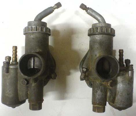
7 K-37 s s on the M-72 M and K-750K K-37 s come in left- and right-side, mirror-images.
8 Round-Slide Throttle Valve K-37 K and K37A Carbs
9 Carburetor K-37 Parts Breakdown (5mv.ru/article.php & Manual for Motorcycle with Sidecar M-72, M City of Irbit, 1954) 1 - Carburetor Body 2 - Round-Slide Throttle Valve 3 - Cover of Float Chamber 4 - Float Needle Valve 5 - Enichener (Tickler) 6 - Float 7 - Connecting Piece 8 - Filter Screen 9 - Main Jet 10 - Atomizer 11 - Air Duct of Atomizer 12 - Jet Needle 13 - Low-Speed (Idle) Jet 14 - Fuel Channel of Idle Jet 15 - Atomizer (Spray Nozzle) Idle Jet 16 - Air Duct of Idle Jet 17 - Filter of Auxiliary Air Duct Idle Jet 18 - Idle Mixture Adjustment Screw 19 - Throttle Slide Stop Screw 20 - Throttle Stroke Limiter 21 - Lock Screw of Idle Jet 22 - Attachment Split-Pin of Jet Needle 23 - Spring 24 - Housing Cover 25 - Union Nut 26 - End of Control Cable 27 - Lock Nut 28 - Control Cable


10 M-72 and K-750, K K-750M, K MB-750 and MT-12 Parts: (RH), 1(RH), (LH) 2(LH) Rubber Boot for Control Cable Throttle Control Cable Tickler for Cold Starting Flange to Engine Cylinder Tickler for Cold Starting Fuel Inlet Ticklers (5), used for starting at cold temp, are clearly seen in the parts diagram. Pressing on the tickler pushes against the float and allows extra fuel.
11 K-37 Carburetor Breakdown in M-72 M Manual Control Cable Guide Tickler for Cold Starting (5) Fuel Inlet Float Chamber Cover (3) Throttle Stroke Limiter (20) Housing Cover (24) Tapered Jet Needle with Cotter Clip Throttle Valve Spring (3) Fuel Shut-Off (Float) Needle (4) Round-Slide Throttle Valve (2) Fuel Float (6) Flange to Engine Cylinder Idle Mixture Adjustment Screw (18) Idle Jet (13) Throttle Slide Stop Screw (19) Main Jet (9)
12 Operation of K-37 K Carburetor Both Right and Left Carburetor Design and Adjustment Are Identical Mirror Images of Each Other Air/Fuel Mixture Adjusted by Controlling Fuel thru Shaped Jet Needle and Vacuum of Main Jet Round-Slide Throttle Valve (3) in Vertical Channel Tapered Jet Needle (7) in Vertical Channel Throttle Valve (3) Pushed Down by Spring (2), between Lid (1) and Valve Maximum Travel of Throttle Valve Limited by Abutment (Slide- Stop) Screw Rise of Throttle Valve Controlled by Cable Main Dosing System Consists of Main Fuel Jet Nozzle (8), Air Chamber (10) with Conduit (11) and Jet Needle (7) Main Jet (9) Screwed into Body of Carburetor Bottom Air from Filter Diffuser Flange to Engine Mixing Chamber At Diffuser Are Two openings for Passage of Air Entering thru Channel (11) Nipple with Strainer at Bottom Filters Fuel Entering from Float Chamber Fuel Idle Injector (6) in Bottom Side of Carburetor Body Air Supply System Idle Carried Out Air Suction Pipe thru Channel (14), a Hole Near the Opening of Main System Channel, as Well as from Ambient thru Opening Protected by Mesh Filter (12), Located in Side of Carburetor Body Idle-Speed Adjusting Screw (5) Regulates Air Entering Carburetor Mixing Chamber Idle (Low-Speed) Operation Fuel from Idling System Goes thru Channel (4) Outlet Located in Mixing Chamber At Low-Speed (Idle), Throttle Valve Closed Fuel Enters Fuel Channel thru Nozzle (6) in Idling Channel (4) Upon Leaving Nozzle (6) Atomizes Air, Going from Environment thru Strainer (12) and Suction of Air thru Carburetor Nozzle (14) Adjust Carburetor at Idle Screw by Limiting Closing Throttle Valve, and Screw (5), Altering Composition of Combustible Mixture With Rise of Throttle Valve, Carburetor Action Enters Main Dosing System
 Fuel from Float Chamber Enters Mixing Chamber thru Main Jet Atomizer (9) and (8) When Fuel Flows into Nozzle, Mixed with Air Coming from Air chamber (10) thru Two Holes Made in Diffuser Air/Fuel")
13 Medium and Full-Throttle Operation of K-37 K Carb (cont.) Fuel from Float Chamber Enters Mixing Chamber thru Main Jet Atomizer (9) and (8) When Fuel Flows into Nozzle, Mixed with Air Coming from Air chamber (10) thru Two Holes Made in Diffuser Air/Fuel Mixture Regulates the Negative Pressure behind Main Jet (9) Composition of Mixture at Medium Loads Mainly Determined by Annular Section between Inner Walls of Atomizer and Tapered Dosing Needle (Jet Needle) When Engine at Constant Position of Throttle Valve, but with Change in Load, Air/Fuel Ratio Adjusted by Air Supplied to the Spray from Air Chamber (10) At Full-Throttle, Round-Slide Valve at Highest Position Provides Rich Fuel Mixture Needed for Maximum Power Adjustment of Mixture Also Set by Size of Main Jets Throttle Slide -Stop Screw Idle Mixture Adjustment Screw Throttle Control Cable Fuel Inlet Flange to Engine Cylinder Tickler (13) Float Chamber
14 Fuel Strainer (8) Fuel Flow and Tickler (5mv.ru/article.php Float Chamber Cast In One Piece with Carburetor Body Reservoir for Fuel Fuel Enters Float Chamber thru Brass Fuel Inlet Nipple, Located in Cover (3) Fuel Quantity Entering Float Chamber Automatically Regulated by Fuel Shut-Off Needle (4), Connected to Hollow Brass Float (6) Bottom of Float Chamber and Lid Have Guide Holes for Float Needle When Filling Float Chamber, Brass Fuel Float Rises with Float Needle Needle s Upper Conical End Fits Hole in Lid, Stopping Further Access of Fuel into Chamber As Fuel Flow from Float Chamber of Float Falls, Needle Hole Opens and Fuel Starts Flowing Again into Fuel Cell Tickler (5) In Float Chamber Cover Temporarily Pushes Down Float to Enrich Mixture when Starting Engine by Increasing Level of Fuel in the Float Chamber From Float Chamber, Fuel Enters Bottom of Carburetor In Bottom of Carb Are Two Concentric Threaded Holes In Smaller, Upper Hole Is Screwed Atomizer (10), which Is Screwed into Main Jet (9), Sealed with Fiber Washer In Larger, Bottom Hole Is Screwed Fitting Hole (7) with Screen Filter (8), Also Sealed with Fiber Washers Fuel Passes from Float Chamber thru Filter Strainer (8) and Chamber of Main Jet 5mv.ru/article.php) Cover (3) Brass Float (6) Fuel Shut-Off Needle (4) Fuel Inlet Nipple Tickler (5) Guide Hole for Float Needle Tickler (5)
 Idle-Speed At Bottom of Carburetor Is Low-Speed (Idle) Jet (13), which Is Screwed into Carb and Has at Top of Calibrated Hole (15) and Two Transverse Holes From the Bottom, Locking Screw of")

 with Lock Nut Over spray in the vertical guide housing carburetor throttle valve is set 2 mounted thereon by means of cotter pins (22) Jet Needle (12) and")
15 Speed (5mv.ru/article.php) Idle-Speed At Bottom of Carburetor Is Low-Speed (Idle) Jet (13), which Is Screwed into Carb and Has at Top of Calibrated Hole (15) and Two Transverse Holes From the Bottom, Locking Screw of Idle Jet (21), which Is Unscrewed for Blowing-Out Nozzle Fuel to Idle System Comes from Float Chamber thru Channel (14) Chamber Connected to Main Jet nozzle of small revolutions through the holes in the carburetor body. Air to the low speed jet is supplied from an air nozzle through the air channel (16) by an additional channel connected to the reticulated air filter (17) Air channel orifice is covered by low speed Idle Speed Adjustment Screw (18) with Lock Nut Over spray in the vertical guide housing carburetor throttle valve is set 2 mounted thereon by means of cotter pins (22) Jet Needle (12) and Spring (23) Throttle Needle Enters Inner Channel of Main Jet Fuel Supplied to Jet by Annular Gap between Channel Wall Nozzle (Needle Jet) and Jet Needle Lower Part of Jet Needle Has Conical Shape Raising Jet Needle, Annular Gap Increases, and Fuel Supplied to Atomizer Increases (Mixture is Enriched) Lock Screw of Idle Jet (21) Idle Jet (13)
16 Jet Needle (5mv.ru/article.php Jet Needle (12) Connected to Throttle Slide Valve (2) Jet Needle Goes into Internal Channel of Main Atomizing Nozzle Fuel Arrives at Atomizer by Circular Gap between Channel Wall of Atomizer and Conical Needle Itself Cotter Clip Pin (2) at Head of Jet Needle Four Openings in Jet Needle Two Holes in Slide Eight Different Provisions of the Needle When Tip is Lower: Leaner Mixture, Higher: Richer Leanest Mixture Obtained Using Upper Hole in Jet Needle with Bottom Hole in Slide Valve Richest Mixture Coincides with Lower Hole in Jet Needle with the Upper Hole in Slide Valve Idling Speed Fed by Small Orifice (13) from Air Supply to Valve (16) thru Filter (17) Cross-Section of Air Duct, and Hence Amount of Air Reaching Low-Speed (Idle) Jet Can Be Changed by Idle Mixture Adjustment Screw (18) 5mv.ru/article.php) Lowest Position of Jet Needle (Lowest Casing Hole and Highest Needle Hole) Highest Position of Jet Needle (Highest Casing Hole and Lowest Needle Hole)
17 Idle Mixture Adjustment Screw (5mv.ru/article.php As Throttle Valve Is Raised, Low-Speed Operation Orifice Gradually Shuts Down and Fuel Starts Spraying thru Main Jet (9) Throttle Valve Has Slant for Outlet Air, and on the Side, Two Longitudinal Grooves One Locking Groove, Eliminating Rotation of Throttle Valve in the Guide other Groove makes it interchangeable for Left and Right Carbs Upper bevel groove rests against Stop Screw (19) with Lock-Nut, designed for installation at low speed carburetor adjustment Spring (23) Presses Down on Throttle Valve Rise of Throttle Valve Limited by Stroke Limiter (20), which Is Screwed into Housing Cover (24) Prevents Excessive Increase engine speed and overloading it. Throttle Valve Connected by Cables with Swivel-Handle Mounted on Right-Side Handle-Bar Essence of Control Is to Eliminate Dead Transitions as You Roll-On the Throttle, Achieved by Installing the Cable Stop (26) Shells into Position and Subsequent Tightening of Lock-Nuts (27) 5mv.ru/article.php)
18 Carburetor Operation at Idle (5mv.ru/article.php As Throttle Valve Is Lifted, It Varies the Cross-Section of the Diffuser (funnel of incoming air), while the Annular Area between the Jet Needle and the Needle Jet (incoming fuel) Inhibition of Fuel with Air Is Carried Out by Supplying Additional Air to the Atomizer, which Reduces the Vacuum Nozzle Due to the Air Outlet of the Spray Along with the Fuel Additional Air Is Channeled thru Auxiliary Air Duct (16) and thru Air Filter (17) When Raising the Throttle Valve Up, the Hole for the Idling Jet (15) Creates a Significant Vacuum that Sucks Air thru the Channels, Providing Engine Power at Low Speeds and Fuel thru the Nozzle (13) Formed in this Emulsion thru Hole (15) Comes into the Air Nozzle Carburetor, which Produces the Mixture Flowing into the Engine Cylinder In This Case, the Main Spray Nozzle Doesn t Work, because It Creates a Minor Vacuum As Throttle Valve Is Lifted, Vacuum in Hole (15) Decreases, and Overspray Increases Because of This, Low-Speed (Idle) Jet Begins to Work Less, and Main Spray Nozzle Gradually Takes Over 5mv.ru/article.php) Flange to Engine Cylinder Mixing Chamber Air Intake Diffuser
 Carburetor at Medium Engine Speeds In the Range of Lifting the Throttle Valve from 1/4 -to- 1/2 Travel Corresponding Increase in Cross-Section of Diffuser Nozzle Low-Speed Gradually Ceases and")
19 Carburetor at Medium and Full Speeds (5mv.ru/article.php) Carburetor at Medium Engine Speeds In the Range of Lifting the Throttle Valve from 1/4 -to- 1/2 Travel Corresponding Increase in Cross-Section of Diffuser Nozzle Low-Speed Gradually Ceases and Main Nozzle Takes Over Dilution Air Decreases Due to Lifting of Slide Valve, Causing Impoverishment of the Working Mixture Conical Jet Needle (12) Rises Simultaneously with Slide Valve, Resulting in Increased Ring Section between Dispenser and Jet Needle Fuel Flow from the Nozzle becomes More Intense, and Mixture Begins to Enrich At Approximately 3/4 Throttle Slide Valve Lifting, Mixture Is Regulated by Throttle Slide Valve and Jet Needle Carb at Full Throttle Opening between the Jet Needle and Dispenser Ring Cross-Section Is So Large that the Amount of Fuel Supplied to the Spray Is No Longer Dependent on Position of Jet Needle, but Determined Only by Size of Main Jet Flange to Engine Cylinder Mixing Chamber Air Intake Diffuser
20 Setting K-301 K / K-302 K / K-37 K Carbs (FoilHeadz Home) 1. Warm up the engine (make sure both sides get hot because many times bikes are only running off of one cylinder). If installed, disconnect the supercharger hose and plug up the carb holes so that absolutely ZERO air passes from one side to the other. Then, kill or ground out one cylinder; we'll set the carb on the other cylinder. 2. Loosen the carb neck screws so that there is slack between the end of the cable casing and the carb neck. 3. Loosen the jam-nuts on the HORIZONTAL (mixture) and DIAGONAL (slide lift) adjustments. 4. Screw the HORIZONTAL screw all the way in. 5. Set the DIAGONAL screw for minimum steady operation. 6. Adjust the HORIZONTAL screw for maximum engine speed. 7. Set the DIAGONAL screw for minimum steady operation again by backing it out 8. Tighten jam-nuts. 9. Repeat for the other side. 10. Note differences in engine speeds when operating on single cylinders. Plug up both cylinders. Adjust the DIAGONAL screws equally for final low-speed idle operation. 11. Tighten jam-nuts. 12. Put it on the center stand (or jack up the drive wheels on an MT-16). 13. Fire it up. 14. Put it in 4th gear (might wanna chock it). 15. Rev it up to km/hr. 16. Clamp/hold the throttle in place, AND DO NOT CHANGE UNTIL THE PROCEDURE IS OVER. 17. Disconnect (or ground) one cylinder wire. 18. Note exactly what the speedometer settles down to after 10 seconds. 19. Now quickly re-connect that side disconnect the other (don't move the throttle even though it'll rev up some). 20. Adjust the carb cable ferrule on the running side to match the exact speed you noted while the first side was running. 21. Now let off the throttle and reconnect your supercharger.
21 Adjusting K-37 K Carbs ( Three adjustments: Throttle Cable Adjustment (26) which Controls Depth of Slide Valve, a Throttle Slide-Stop Screw (19) that More or Less "fine tunes" the Slide Valve, and Idle Mixture Adjustment Screw (18) that Sets Air / Fuel Ratio Cautions: Spare Needles and Other Parts are Hard to Find Parts DO Fall Off If Lock Nuts Aren t Tight. Also, they do require pretty regular tweaking to keep things running smooth. Suspect Carb Problems, Indicated by Excessive Backfiring, Difficulty Starting Even with Good Spark, or Having Boots Soaked with Gasoline... There Are Few Things to Check before Tearing Things Apart Ensure Good Spark and Points and Plugs Are Gapped Properly Check Color of Spark Plugs Should Be a Nice Brown Color Realistically Usually Dark, but Shouldn't Be Caked with Carbon Check Floats Cut Fuel Off and Drain Bowls by Loosening the Lower Filter (7) Pull Float Covers and Make Sure Float Is Seated Correctly with Plenty of Free Travel Check Air Intake Tubes for Leaks Check Nuts Holding Carb Body to Cylinder Head Check for Good Fuel Flow from Tank, Even on Both Sides Determine Running Rich or Lean, As Indicated by Spark Plug Color Two Screen Filters Need to Be Checked If You're Lean: In Petcock (fuel tap) under Tank at Top of Bowl and / or Another Inside Bowl In Carburetor: Wrapped around Fuel Port in Lower Filter Plug (7) If Filters are clean and Idle / Throttle Adjustments Are Good, then Mixture Should Be Adjusted Fuel Control Mixture Screw; so CCW (out) Is Rich and CW (in) Is Lean Rule of Thumb Is that If Mix Adjustment Is On Outflow Side (next to the cylinder), Then It's a Fuel Control Screw and CCW = Rich and CW = Lean
22 Balancing Carbs & Setting Idle Adjustment ( Remove Breathers to Access the Bottom of the Round Throttle Slide (2) Loosen Lock Nuts on Cable Adjustment Screws (27) and Slide Stop Adjustments (19) Turn Out Stop Adjustments (19) until They're Loose Insert a 6mm Drill Bit into Bottom of Breather Intake Adjust Cable Screw until Base of Throttle Slide Resting on Top of the 6 mm Bit Tighten Down Lock Nuts on Cables and Turn Stop Adjustments Back In until They Just Make Contact with Throttle Slide Assuming Your Mixture Screws Are Original and Both The Same Size, Back Them Out about Halfway and Use a Set of Dividers to Measure the Thread Distance from Carb Body, Setting Them Both the Same Fire Up the Bike, Set the Spark Advance Lever Forward Pull One Plug Wire and Adjust Stop Screw until That Cylinder Is Running Smooth Turn the Mixture Screw In until the Cylinder Starts to Choke Out, then Back It Off Slowly until Everything Sounds Right Plug in Other Cylinder, Unplug First One, and Repeat Process Tuning It by Ear to Match First Cylinder as Closely as Possible Now Shut It Off and Let Engine Cool Down Block Front and Hack Wheels and Jack-Up Back of Bike so Pusher (rear wheel) Is Free Crank It Up Again and Work It to 4th gear. (You need somebody to hold the throttle open now at a good RPM unless it stays in place by itself as most of the older ones do.) Readjust Mixture Screws Using Same procedure as Before, One Cylinder at a Time. Do This Quick to Prevent Excessive Strain on the Engine If Problems Persist, then Likelihood Is a Clogged Port Somewhere Carefully Take Carbs Apart and Blow Everything Out with a Compressor, Then Start Over
23 Carburetor Balancing (FoilHeadz Home) Method is Idiot-Proof and Has Been in Use for Generations Bet There's Not a Single Twin Max in China or Former Soviet Union If You Can Tell When Engine Is at Maximum and Minimum Rev s, You Can Easily and Accurately Set Idle and Balance on Your Carbs Relies on Rev Balancing and Not on Vacuum Measurements (mm Hg/vacuum) Using a Balancer Assumes There are Equal Conditions in Both Cylinders Just Too Many Variables: Spark Plugs, HT Wires, Hot Spots in Cylinders, Compression Variance, Crud on Jets, Valve Leakage, etc Setting Carbs Properly Is a Two-Step Process First, Set Idle Using Adjustment Screw (18) The Adjustment Screw Only Affect the Idle Speed! Then, Sync the Throttle Slides to Make Sure Both Cylinders Are Running at the Same Speed for the Same Throttle Position Basically Want to Ensure that One Jug Is Not Running at 30 mph, while Other Jug Is Running at 50 mph May Want to Set-Up a Fan to Keep Engine Cool Once You Understand, the Whole Process Can Be Done in Less than 10 minutes Some folks prefer to match rpm s of cylinders, which takes into account the total performance of each cylinder.
24 Balancing Carbs (Manual for Motorcycle with Sidecar M-72, M City of Irbit, 1954) Desired Equal Effort of Two Engine Cylinders Ensured by Simultaneous Function of Carbs Each Carburetor Separately Tuned in Following Order: 1. Clean Carburetor 2. Start and Warm-Up Engine 3. Set Ignition Setting Lever to Idle Retard 4. Loosen Lock Nut and Throttle Slide-Stop Screw (19) Loosen and adjust so far tighten that Round-Slide (2) is easily lifted and the engine makes increase RPM 5. Firmly Tighten Idle Mixture Adjustment Screw (18) for Adjustment of Mixture after the engine rpm s Decrease, by loosening Screw (19) 6. No-load operation-nozzle-attentively the work of the engine adjust, the screw 18 for the adjustment of the mixture loosen and such a position give, at which the engine with highest number of revolutions works evenly. Then the screw 19 unscrew and the number of revolutions to the extreme reduce. As soon as the adjustment has been completed one must secure the screws (18) and (19) by lock nuts 7. Raise Slide of Carburetor which can be adjusted by hand in place of the cable, if thereby an increase of the number of revolutions is reached. Thus the attitude is terminated. Adjust the second carburetor in the same manner Balancing or Synchronizing Carburetors Jack Up the Motorcycle Start Engine and Shift into 4 th gear Then switch a cylinder off (Remove Ignition Cable) Increase number of revolutions of Engine, until Speedometer Indicates 30 km/hr Some minutes with this function wait, then the working cylinder off switch and the other cylinder on switch. If one opens or closes the butterfly valve somewhat, one achieves the same tachometer stand with the help of the cable delimitation. Since such an adjustment lasts a long time, one must be careful not to overheat the engine.
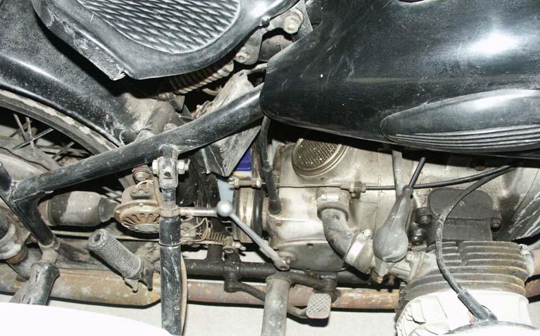
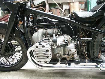
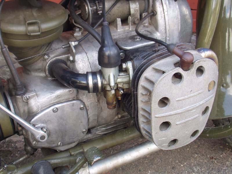
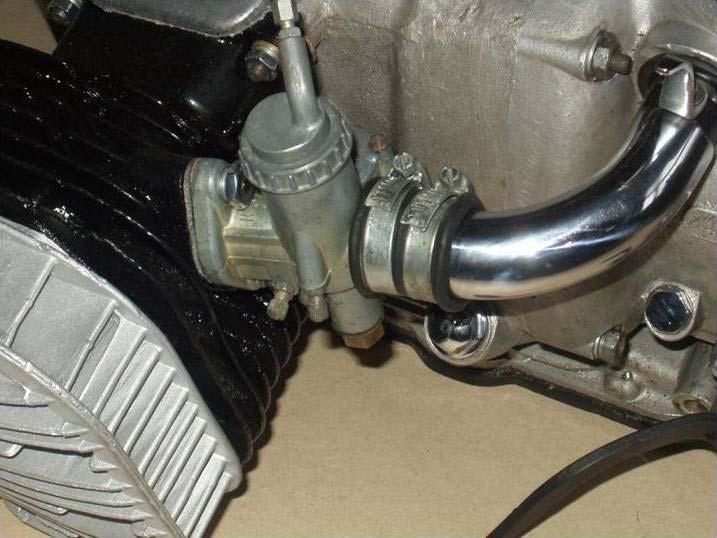
25 M-72 Side-View Showing K-37 K Carburetor
26 M-72 Top-View Showing K-37 K Carburetors


27 Individual Parts Idle Mixture Adjust Screw Rubber Cover Many carb parts, such as the rubber cover and metering pin, are interchangeable between the K-37 and the PZ-28.
Днепр) Russian Motorcycle Carburetors. Carburetors
 Russian Motorcycle Carburetors. Carburetors") Ural (Урал( Урал) - Dnepr (Днепр( Днепр) Russian Motorcycle Carburetors Rev. 1 Part 2A: PZ-24 and PZ-28 Carburetors (see also Part: 2 K-37 K Carburetor and Part 2B: PZ-24 and PZ-28 Carburetor Assembly
Ural (Урал( Урал) - Dnepr (Днепр( Днепр) Russian Motorcycle Carburetors Rev. 1 Part 2A: PZ-24 and PZ-28 Carburetors (see also Part: 2 K-37 K Carburetor and Part 2B: PZ-24 and PZ-28 Carburetor Assembly
Урал) - Dnepr (Днепр) Russian Motorcycle Carburetors
 - Dnepr (Днепр) Russian Motorcycle Carburetors") Ural (Урал( Урал) - Dnepr (Днепр) Russian Motorcycle Carburetors Part 8A: Adjustment and Overhaul of the Pekar K-65 Carburetors (see also Part 8-8 K-65 Carburetor and Part 8B- Setting Up K-65 K Carbs)
Ural (Урал( Урал) - Dnepr (Днепр) Russian Motorcycle Carburetors Part 8A: Adjustment and Overhaul of the Pekar K-65 Carburetors (see also Part 8-8 K-65 Carburetor and Part 8B- Setting Up K-65 K Carbs)
Днепр) Russian Motorcycle Carburetors
 Russian Motorcycle Carburetors") Ural (Урал( Урал) - Dnepr (Днепр( Днепр) Russian Motorcycle Carburetors Part 1: Introduction- Carburetor (Карбюраторыъ( Карбюраторыъ) Evolution for Russian Sidecars Ernie Franke eafranke@tampabay.rr.com
Ural (Урал( Урал) - Dnepr (Днепр( Днепр) Russian Motorcycle Carburetors Part 1: Introduction- Carburetor (Карбюраторыъ( Карбюраторыъ) Evolution for Russian Sidecars Ernie Franke eafranke@tampabay.rr.com
Днепр) Russian Motorcycle Carburetors Part 2B: PZ-24 and PZ-28 Carburetor Assembly and Jet Drilling
 Russian Motorcycle Carburetors Part 2B: PZ-24 and PZ-28 Carburetor Assembly and Jet Drilling") Ural (Урал( Урал) - Dnepr (Днепр( Днепр) Russian Motorcycle Carburetors Part 2B: PZ-24 and PZ-28 Carburetor Assembly and Jet Drilling (applies also to K-37 K and K-38 K carbs) Ernie Franke eafranke@tampabay.rr.com
Ural (Урал( Урал) - Dnepr (Днепр( Днепр) Russian Motorcycle Carburetors Part 2B: PZ-24 and PZ-28 Carburetor Assembly and Jet Drilling (applies also to K-37 K and K-38 K carbs) Ernie Franke eafranke@tampabay.rr.com
Carburetor Instructions
 Carburetor Instructions for HUDSON SUPER SIX ESSEX SIX CYLINDER Hudson Motor Car Co. DETROIT, U.S.A. Carburetor The carburetor is a device for metering correct amounts of fuel and air for the various
Днепр) Russian Motorcycle Carburetors Part 11: VM 28mm Mikuni
 Russian Motorcycle Carburetors Part 11: VM 28mm Mikuni") Ural (Урал( Урал) - Dnepr (Днепр( Днепр) Russian Motorcycle Carburetors Part 11: VM 28mm Mikuni (See Also Part 11A: VM Mikuni Carb Manual) Ernie Franke eafranke@tampabay.rr.com 04/2011 Mikuni VM-28 Round-Slide
Ural (Урал( Урал) - Dnepr (Днепр( Днепр) Russian Motorcycle Carburetors Part 11: VM 28mm Mikuni (See Also Part 11A: VM Mikuni Carb Manual) Ernie Franke eafranke@tampabay.rr.com 04/2011 Mikuni VM-28 Round-Slide
Russian Motorcycle Carburetors
 Ural (Урал) - Dnepr (Днепр) Russian Motorcycle Carburetors Part V-12: VM 28mm Mikuni (See Also Part V-12A: VM Mikuni Carb Manual and Part V-12B: Mikuni Overhaul) Ernie Franke eafranke@tampabay.rr.com 03
KEIHIN CARBURATORS FOR 4-CYLINDER HONDA MOTORCYCLES
 KEIHIN CARBURATORS FOR 4-CYLINDER HONDA MOTORCYCLES Set of 4 Keihin carburetors marked 089A and used on 1976 CB550K GENERAL NOTES: All carburetors perform the same function: mixing air and fuel for supply
INSIDE YOUR HOLLEY CARBURETOR FUEL INLET SYSTEM
 INSIDE YOUR HOLLEY CARBURETOR The carburetor is quite simply a fuel metering device that operates under the logical and straightforward laws of physics. It has evolved over the years from a very simple
TILLOTSON LTD., CLASH INDUSTRIAL ESTATE, TRALEE, CO. KERRY, IRELAND PHONE: FAX:
 TILLOTSON LTD., CLASH INDUSTRIAL ESTATE, TRALEE, CO. KERRY, IRELAND PHONE: +353 66 7121911 FAX: +353 66 7124503 e-mail: sales@tillotson.ie SERIES SERVICE MANUAL INTRODUCTION The gasoline engine industry
7. FUEL SYSTEM ('04 - '05)
") 7. FUEL SYSTEM ('04 - '05) SYSTEM COMPONENTS 7-2 CARBURETOR DISASSEMBLY 7-81 SERVICE INFORMATION 7-3 CARBURETOR ASSEMBLY 7-14 TROUBLESHOOTING 7-4 CARBURETOR INSTALLATION 7-21 AIR CLEANER HOUSING 7-5 PILOT
7. FUEL SYSTEM ('04 - '05) SYSTEM COMPONENTS 7-2 CARBURETOR DISASSEMBLY 7-81 SERVICE INFORMATION 7-3 CARBURETOR ASSEMBLY 7-14 TROUBLESHOOTING 7-4 CARBURETOR INSTALLATION 7-21 AIR CLEANER HOUSING 7-5 PILOT
THE IDLE CIRCUIT AND THE PROGRESSION. We have seen how in a "basic"
 THE IDLE CIRCUIT AND THE PROGRESSION Manufacture and operation of two very important systems, which allow the practical use of a carburetor for motorcycles We have seen how in a "basic" (simplified) carburetor,
THE CARBURETOR: THE ADDITIONAL SYSTEMS
 THE CARBURETOR: THE ADDITIONAL SYSTEMS From the acceleration pump to the power jet: the special configuration of circuits that apply to some carburetor models As stated in the previous article, a carburetor
BA /02/03/04/06/07/08/13/13B/15 BIG AIR KIT (BAK) - Yamaha Road Star (99-07)
 - Yamaha Road Star (99-07)") BA-2020-00/02/03/04/06/07/08/13/13B/15 BIG AIR KIT (BAK) - Yamaha Road Star (99-07) Page: 1 Revision: 6.2-02/23/2011 Install Time: 1.5 Hours We recommend a qualified Yamaha technician install this kit
BA-2020-00/02/03/04/06/07/08/13/13B/15 BIG AIR KIT (BAK) - Yamaha Road Star (99-07) Page: 1 Revision: 6.2-02/23/2011 Install Time: 1.5 Hours We recommend a qualified Yamaha technician install this kit
HSR Carburetor Easy Kits Installation Instructions For Evo Big Twin Kit: # 42-7 Twin Cam Kit: # 42-18
 HSR Carburetor Easy Kits Installation Instructions For Evo Big Twin Kit: # 42-7 Twin Cam Kit: # 42-18 Revised 5/01/01 EK-1 Easy Kit Installation Instructions The HSR series carburetors are precise yet
SECTION 4 - FUEL/LUBRICATION/COOLING
 For Arctic Cat Discount Parts Call 606-678-9623 or 606-561-4983 SECTION 4 - FUEL/LUBRICATION/COOLING 4 TABLE OF CONTENTS Carburetor Specifications... 4-2 Carburetor Schematic... 4-2 Carburetor... 4-3 Cleaning
HW Prowler Carburetor Installation Instructions
 HW Prowler Carburetor Installation Instructions Page 1 of 6 Carb Kit Contains: HW modified Mikuni 36mm pumper style carb Custom choke cable Fuel Line Clamp Instructions (2) Leaner and (2) richer main jets
I.C Engine Topic: Fuel supply systems Part-1
 I.C Engine Topic: Fuel supply systems Part-1 By: Prof.Kunalsinh Kathia Essential parts of carburetor Fuel strainer Float chamber Metering and idiling system Choke and throttle Fuel strainer As gasoline
Ural (Урал( Днепр) Russian Motorcycle Carburetors Part 18: Identification and Comparative Pricing. Ernie Franke 09/2010
 Russian Motorcycle Carburetors Part 18: Identification and Comparative Pricing. Ernie Franke 09/2010") Ural (Урал( Урал) Dnepr (Днепр( Днепр) Russian Motorcycle Carburetors Part 18: Identification and Comparative Pricing Ernie Franke eafranke@tampabay.rr.com 09/2010 Russian Carburetor TimeLine (09/2012)
Ural (Урал( Урал) Dnepr (Днепр( Днепр) Russian Motorcycle Carburetors Part 18: Identification and Comparative Pricing Ernie Franke eafranke@tampabay.rr.com 09/2010 Russian Carburetor TimeLine (09/2012)
Днепр) Russian Motorcycle Carburetors. Carburetor
 Russian Motorcycle Carburetors. Carburetor") Ural (Урал( Урал) - Dnepr (Днепр( Днепр) Russian Motorcycle Carburetors Part 7B: Setting Up K-63/KK 63/K-6565 Carbs (see also Part 7: K-63 K Carburetor and Part 7A- Pekar K-63 Carbs) Ernie Franke for William
Ural (Урал( Урал) - Dnepr (Днепр( Днепр) Russian Motorcycle Carburetors Part 7B: Setting Up K-63/KK 63/K-6565 Carbs (see also Part 7: K-63 K Carburetor and Part 7A- Pekar K-63 Carbs) Ernie Franke for William
TECH INFORMATION EMPI D Performance 2-Barrel Carburetor
 TECH INFORMATION EMPI D Performance 2-Barrel Carburetor The New EMPI D 2-Barrel Performance Carburetor.Built specifically for the VW Aftermarket. With all the features that you have asked for More Progression
Tillotson Tc3A Carburator
 Tillotson Tc3A Carburator 176 FUEL SYSTEMS - 5B-11 CENTER BOWL TYPE CARBURETOR Removal 1. Remove front cowl cover and wrap-around cowl. 2. Remove swivel link from lower carburetor. (Figure 2) 3. Loosen
THE IDIOT S GUIDE TO TUNING SU CARBURETTERS
 THE IDIOT S GUIDE TO TUNING SU CARBURETTERS There are four distinct phases to tuning SU carburetters (carbies). The first is to set the fuel level in the float bowl, the second is to centre the needle
5. FUEL SYSTEM 5-0 FUEL SYSTEM MXU 250R/300R
 5 FUEL SYSTEM 5 SERVICE INFORMATION------------------------------------------------ 5-2 TROUBLESHOOTING----------------------------------------------------- 5-3 FUEL TANK -----------------------------------------------------------------
AN EXPLANATION OF CIRCUITS CARTER YH HORIZONTAL CLIMATIC CONTROL CARBURETER
 AN EXPLANATION OF CIRCUITS CARTER YH HORIZONTAL CLIMATIC CONTROL CARBURETER The Carter Model YH carbureter may be compared with a Carter YF downdraft carbureter with the circuits rearranged to operate
PIERBURG. Carburetor: 2E3
 PIERBURG Carburetor: 2E3 1 fast idle adjusting screw 2 throttle lever 3 fuel mixture adjusting screw 4 main body 5 idle cut off valve 6 stop screw 7 accelerator pump cover 8 diaphragm 9 spring 10 valve
HSR Carburetor. Total Kits. Installation Instructions. # Evo Big Twin # present Twin Cam
 HSR Carburetor Total Kits Installation Instructions HSR42 Kits: HSR45 Kits: #42-8 84-99 Evo Big Twin #42-19 99 - present Twin Cam #45-2 84-99 Evo Big Twin #45-3 84-99 Evo Big Twin #45-4 99 - present Twin
HSR Carburetor. Total Kits. Installation Instructions. # Evo Big Twin # present Twin Cam
 HSR Carburetor Total Kits Installation Instructions HSR42 Kits: HSR45 Kits: #42-8 84-99 Evo Big Twin #42-19 99 - present Twin Cam #45-2 84-99 Evo Big Twin #45-3 84-99 Evo Big Twin #45-4 99 - present Twin
Jetting and understanding your CV carburetor
 Jetting and understanding your CV carburetor What do all these pieces do? You may also ask, how or why would I do this to my carb? The goal of this article is to unravel the mystery of carburetor jetting
QUICK FUEL TECHNOLOGY HOT ROD SERIES CARBURETORS SLAYER SERIES CARBURETORS SUPER STREET SERIES CARBURETORS
 QUICK FUEL TECHNOLOGY Installation Instructions HOT ROD SERIES CARBURETORS SLAYER SERIES CARBURETORS SUPER STREET SERIES CARBURETORS HR-580-VS 580 CFM Vac. Secondary!!! SS-680-VS 680 CFM Vac. Secondary
CARTER DOWNDRAFT CARBURETOR Terraplane All Models. Technical Information
 CARTER DOWNDRAFT CARBURETOR 1934 Terraplane All Models Technical Information . Carter W-1 Downdraft Carburetors 1934 Terraplane Challenger, Model KS NOTE: Terraplane Models. Carburetor fitted with Anti-
FUEL SYSTEM. Table of Contents. Specifications. Section 3A Fuel Delivery System. Models 6/8/9.9/10/15 CARBURETOR SPECIFICATIONS
 FUEL SYSTEM Section 3A Fuel Delivery System Table of Contents Specifications............................. 3A-1 WMC Carburetor Specifications............. 3A-2 WMC Carburetor Specifications.............
TILLOTSON LTD., CLASH INDUSTRIAL ESTATE, TRALEE, CO. KERRY, IRELAND PHONE: FAX:
 TILLOTSON LTD., CLASH INDUSTRIAL ESTATE, TRALEE, CO. KERRY, IRELAND PHONE: +353 66 7121911 FAX: +353 66 7124503 e-mail: sales@tillotson.ie HU SERIES SERVICE MANUAL INTRODUCTION To keep apace of new market
TILLOTSON LTD., CLASH INDUSTRIAL ESTATE, TRALEE, CO. KERRY, IRELAND PHONE: FAX:
 TILLOTSON LTD., CLASH INDUSTRIAL ESTATE, TRALEE, CO. KERRY, IRELAND PHONE: +353 66 7121911 FAX: +353 66 7124503 e-mail: sales@tillotson.ie HS SERIES SERVICE MANUAL INTRODUCTION The demand for a miniature
03. Fuel and Air Feed System
 Page 11 of 03. Fuel and Air Feed System Content (16 Marks) 3.1 Petrol fuel supply system. 8 Marks Conventional Petrol Engine: Gravity feed, Pump feed (Layout,Function of Components and location). Construction
ZAMA CUBE CARBURETOR DISASSEMBLY AND SERVICE
 ZAMA CUBE CARBURETOR DISASSEMBLY AND SERVICE MIXTURE SCREWS Remove idle and main mix ture screw. Inspect each screw for damage, especially the needle points which should have no deformation of the tapered
Moped Hospital Racing. Installation of performance parts MANUAL. Tecnigas Extreme Super 9
 Moped Hospital Racing Installation of performance parts MANUAL Tecnigas Extreme Super 9 Page 2 These pages are to help the shop/person installing the parts that we sell. It is a general explanation of
"F" SERIES (Cont.) AIR FILTER ASSEMBLY NOTE NOTE. To remove grasp the cover, loosen snap and. If engine is flooded, fuel can drain back into
 AIR FILTER ASSEMBLY NOTE NOTE. To remove grasp the cover, loosen snap and. If engine is flooded, fuel can drain back into") CARB.-AIR-FILTER ASSEMBLY GASKET RETAINER PASSAGE AIR FILTER ASSEMBLY AIR FILTER If engine is flooded, fuel can drain back into filter. As filter becomes saturated, incoming air picks up more fuel, causing
CARB.-AIR-FILTER ASSEMBLY GASKET RETAINER PASSAGE AIR FILTER ASSEMBLY AIR FILTER If engine is flooded, fuel can drain back into filter. As filter becomes saturated, incoming air picks up more fuel, causing
Motorcycle Carburetor Theory 101
 Motorcycle Carburetor Theory 101 Motorcycle carburetors look very complex, but with a little theory, you can tune your bike for maximum performance. All carburetors work under the basic principle of atmospheric
Simple Carburettor Fuel System for a Piston Engine. And how it works
 Simple Carburettor Fuel System for a Piston Engine And how it works Inlet Exhaust Tank PISTON ENGINE Carburettor Fuel System Filler Cap COCKPIT FUEL GAUGE E FUEL 1/2 F Filler Neck Tank Cavity FUEL LEVEL
5. FUEL SYSTEM 5-0 FUEL SYSTEM UXV 500
 5 FUEL SYSTEM 5 SERVICE INFORMATION------------------------------------------------ 5-02 TROUBLESHOOTING----------------------------------------------------- 5-03 FUEL TANK -----------------------------------------------------------------
Tuning A Walbro Carb. Walbro Carb TUNE UP & Illustrated Guide
 Tuning A Walbro Carb Walbro Carb TUNE UP & Illustrated Guide by M. B. Fuess Walbro carbs aren t too difficult to tune up if you know what you re doing. First of all, you need to know how the carb works
Mikuni RS Carburetor Conversion
 Mikuni RS Carburetor Conversion After putting your carbies on the bench or the kitchen table if the wife is out, you will see that the linkages may be in different positions depending on which brand of
4. FUEL SYSTEM CK 1 4-0
 4 4 4-0 SERVICE INFORMATION... 4-1 FLOAT LEVEL INSPECTION... 4-5 TROUBLESHOOTING... 4-2 CARBURETOR INSTALLATION... 4-6 THROTTLE VALVE DISASSEMBLY... 4-3 THROTTLE VALVE ASSEMBLY... 4-6 CARBURETOR REMOVAL...
5. FUEL SYSTEM FUEL SYSTEM 5-0
 5 FUEL SYSTEM 5-0 SERVICE INFORMATION GENERAL INSTRUCTIONS SERVICE INFORMATION...5-1 CARBURETOR INSTALLATION...5-9 TROUBLESHOOTING...5-1 PILOT SCREW ADJUSTMENT...5-10 CARBURETOR REMOVAL...5-2 AUTO BYSTARTER...5-3
Vacuum Readings for Tuning and Diagnosis
 Vacuum Readings for Tuning and Diagnosis -Henry P. Olsen Once you learn to properly interpret its readings, a vacuum gauge can be one of the most useful tools in your toolbox. 22 FEATURE Some people consider
FUEL SYSTEM/CARBURETOR/FUEL PUMP
 13 FUEL SYSTEM/CARBURETOR/FUEL PUMP FUEL SYSTEM-------------------------------------------------------------------------------------13-1 SCHEMATIC DRAWING-------------------------------------------------------------------------13-2
12. CARBURETOR 12-0 CARBURETOR VITALITY 50
 12 12 CARBURETOR SERVICE INFORMATION (2-STROKE)... 12-2 SERVICE INFORMATION (4-STROKE)... 12-3 THROTTLE VALVE (2-STROKE)... 12-5 CARBURETOR (2-STROKE)... 12-7 AIR SCREW ADJUSTMENT (2-STROKE)... 12-13 REED
9.7 Replacement of the compressed air distributor
 9.6.6 9.6.7 screw in the bolt and to increase unscrew the bolt. For a complete rotation of the bolt, the variation is of 1mm. After measuring the pointer position and the compensatory adjustment screw
HE Stewart Vacuum Gasoline System employs a small tank, installed under the hood. This tank is connected by brass tubing to the intake manifold, also
 T HE Stewart Vacuum Gasoline System employs a small tank, installed under the hood. This tank is connected by brass tubing to the intake manifold, also to gasoline supply tank, and to carburetor. Every
13. FUEL SYSTEM/CARBURETOR/
 13 FUEL SYSTEM/CARBURETOR/FUEL PUMP FUEL SYSTEM --------------------------------------------------------- 13-1 SCHEMATIC DRAWING ---------------------------------------------- 13-2 OPERATION OF CARBURETOR
MIKUNI VM26 Carburetor Kit Instruction Manual
 MIKUNI VM26 Carburetor Kit Instruction Manual (For exclusive use in the Super Head 4VALVE+R-equipped motorcycle) Item No. (Carburetor set) AKEGAWA-made products. Please strictly follow the following instructions
12. CARBURETOR/FUEL PUMP
 12 CARBURETOR/FUEL PUMP SERVICE INFORMATION... 12-2 TROUBLESHOOTING... 12-2 THROTTLE VALVE DISASSEMBLY... 12-3 THROTTLE VALVE INSTALLATION... 12-4 CARBURETOR REMOVAL... 12-5 AUTO BYSTARTER... 12-6 FLOAT
CARBURETOR SERVICE INFORMATION TROUBLESHOOTING THROTTLE VALVE DISASSEMBLY THROTTLE VALVE INSTALLATION...
 11 CARBURETOR SERVICE INFORMATION... 11-2 TROUBLESHOOTING... 11-2 THROTTLE VALVE DISASSEMBLY... 11-3 THROTTLE VALVE INSTALLATION... 11-4 CARBURETOR REMOVAL... 11-5 AUTO BYSTARTER... 11-6 FLOAT CHAMBER...
Typical Install Instructions
 Typical Install Instructions Read & understand all steps of these instructions before beginning this installation. WEBER Conversion Kit, VW T-1/2, up to 1835cc 32 / 36 DFEV Weber Carburetor These instructions
ENGINE AND EMISSION CONTROL
 17-1 GROUP 17 ENGINE AND EMISSION CONTROL CONTENTS ENGINE CONTROL........... 17-3 GENERAL INFORMATION....... 17-3 SERVICE SPECIFICATIONS..... 17-3 ON-VEHICLE SERVICE.......... 17-3 ACCELERATOR CABLE CHECK
ENGINE AND EMISSION CONTROL
 17-1 GROUP 17 ENGINE AND EMISSION CONTROL CONTENTS ENGINE CONTROL.......... 17-3 GENERAL INFORMATION...... 17-3 SERVICE SPECIFICATIONS..... 17-3 TROUBLESHOOTING.......... 17-3 INTRODUCTION TO ENGINE CONTROL
Holley High Performance Intake System* For Port 13B Engines (Includes B 6-Port engines converted to 4-Port)
") Holley High Performance Intake System* For 1974-1978 4-Port 13B Engines (Includes 1984-85 13B 6-Port engines converted to 4-Port) Installation Instructions I-18038 Note: These instructions assume: The
Holley High Performance Intake System* For 1974-1978 4-Port 13B Engines (Includes 1984-85 13B 6-Port engines converted to 4-Port) Installation Instructions I-18038 Note: These instructions assume: The
Version 1.4 Operating instructions Czech Republic
 Version 1.4 Operating instructions Czech Republic Please check updates of operating instructions at www.rotomotor.cz, that your engine has still the best care. (can happen important changes that will lead
Backwater Performance Systems Large Vanguard Mikuni Twin Carburetor Kit
 Backwater Performance Systems Large Vanguard Mikuni Twin Carburetor Kit 1. Throttle Cable Twin (CKC-41) 2. Carburetor VM30mm (CKC-40) 3. Loctite 242.5mL (A-210) 4. Air Cleaner Filter 6000 (EC-86) 5. Rev
TILLOTSON LTD., CLASH INDUSTRIAL ESTATE, TRALEE, CO. KERRY, IRELAND PHONE: FAX:
 TILLOTSON LTD., CLASH INDUSTRIAL ESTATE, TRALEE, CO. KERRY, IRELAND PHONE: +353 66 7121911 FAX: +353 66 7124503 e-mail: sales@tillotson.ie HR SERIES SERVICE MANUAL INTRODUCTION Tillotson has developed
SECTION 4 - FUEL SYSTEMS AND CARBURETION
 SECTION - FUEL SYSTEMS AND CARBURETION FUEL SYSTEMS - - - - - - - - - - - - - - - - - - - - - - - - - - - - - - - - - - - - - - - - - - - - - - - - - - - - - - - - - - - - - -62 FUEL PUMP - - - - - - -
BASIC INSTRUCTIONS SHIFTER KZ1 / KZ2 e X30 SHIFTER-TaG
 BASIC INSTRUCTIONS SHIFTER KZ1 / KZ2 e X30 SHIFTER-TaG FEEDING: by fuel mixture 98NO (min. 95NO) and 4% oil (CIK homologated). ATTENTION: the engine is supplied without oil in the gearbox. GEARBOX OIL
Automobile section, showing different parts in detail. and miscellaneous devices.
 SECTION VII Nos. 97 112 Automobile section, showing different parts in detail. and miscellaneous devices. Hydraulic jack MECHANICAL MODELS 43 Section VII 97. Automobile engine starter. This device known
5-2 FUEL SYSTEM AND THROTTLE BODY FUEL SYSTEM FUEL DELIVERY SYSTEM The fuel delivery system consists of the fuel tank, fuel pump, fuel filters, fuel f
 FUEL SYSTEM AND THROTTLE BODY 5-1 FUEL SYSTEM AND THROTTLE BODY I CONTENTS FUEL SYSTEM 5-2 FUEL DELIVERY SYSTEM 5-2 FUEL PUMP 5-3 FUEL PRESSURE REGULATOR 5-4 FUEL INJECTOR 5-4 FUEL PUMP CONTROL SYSTEM
BRAWLER SERIES CARBURETORS
 BRAWLER SERIES CARBURETORS Installation Instructions Please Stop and Read these Instructions before proceeding. If you do not fully understand the installation and tuning instructions you should seek professional
CARBURETION. Flo-Jet Carburetors. One Piece. One-Piece Flo-Jet. Main Jet Adjustment N eedle
 One Piece One-Piece Flo-Jet The small One-Piece Flo-Jet carburetor is illustrated in Fig. 122 and was used on early Model 170700. These are float feed carburetors with adjustable orifice main jet needle
2) Rich mixture: A mixture which contains less air than the stoichiometric requirement is called a rich mixture (ex. A/F ratio: 12:1, 10:1 etc.
 Rich mixture: A mixture which contains less air than the stoichiometric requirement is called a rich mixture (ex. A/F ratio: 12:1, 10:1 etc.") Unit 3. Carburettor University Questions: 1. Describe with suitable sketches : Main metering system and Idling system 2. Draw the neat sketch of a simple carburettor and explain its working. What are the
Unit 3. Carburettor University Questions: 1. Describe with suitable sketches : Main metering system and Idling system 2. Draw the neat sketch of a simple carburettor and explain its working. What are the
A. Perform a vacuum gauge test to determine engine condition and performance.
 ENGINE REPAIR UNIT 2: ENGINE DIAGNOSIS, REMOVAL, AND INSTALLATION LESSON 2: ENGINE DIAGNOSTIC TESTS NOTE: Testing the engine s mechanical condition is required when the cause of a problem is not located
Catalytic Failures. Engine running too hot.
 Catalytic Failures It is not uncommon for technicians to misdiagnose a driveability or emissions issue by blaming the converter. In many cases, it s not the converter s fault, but rather one of the engine
Cold Air Intake Installation Instructions
 BAVARIAN AUTOSPORT Cold Air Intake Installation Instructions PARTS LIST: PF BMWE36-4 PROCEDURE: 1. Using a flat-head screwdriver, loosen the hose clamp between the AFM and rubber boot leading to engine
Body type location. Model number location. Small Engine Parts
 Body type location Model number location Small Engine Parts FUEL PUMP SYSTEM SYSTEMS AND OPERATION The fuel pump on a diaphragm carburetor uses the vacuum and pressure pulse from the engines crankcase
PLEASE NOTE: This is a PRELIMINARY copy of the Carburetor Reference Manual.
 PLEASE NOTE: This is a PRELIMINARY copy of the Carburetor Reference Manual. Carburetor Service Kits The carburetors for most current production engines are serviced with convenient kits, which include
4. FUEL SYSTEM 4-0 FUEL SYSTEM NEXXON 50
 4 FUEL SYSTEM SERVICE INFORMATION ------------------------------------------------ 4-2 TROUBLESHOOTING----------------------------------------------------- 4-3 AIR CLEANER REMOVAL -----------------------------------------------
Setting up and adjusting SU/Hitachi carbs on the Datsun Roadster by Keith Williams. Service screw
 Setting up and adjusting SU/Hitachi carbs on the Datsun Roadster by Keith Williams Service screw This is the service screw it s only use it to raise the engine speed while adjusting the carbs. In normal
ENGINE AND EMISSION CONTROL
 -1 ENGINE CONTROL.......... GENERAL INFORMATION...... SERVICE SPECIFICATIONS..... ON-VEHICLE SERVICE......... ACCELERATOR CABLE CHECK AND ADJUSTMENT.................... ACCELERATOR CABLE AND PEDAL......................
11. CARBURETOR 11-0 CARBURETOR ZX / SCOUT 50
 11 CARBURETOR SERVICE INFORMATION... 11-2 TROUBLESHOOTING... 11-2 THROTTLE VALVE DISASSEMBLY... 11-3 THROTTLE VALVE INSTALLATION... 11-4 CARBURETOR REMOVAL... 11-5 AUTO BYSTARTER... 11-6 FLOAT CHAMBER...
COLT 2310, 2510, AND 2712 COM PACT TRACTORS CHAPTER 9 TROUBLESHOOTING AND ANALYSIS
 COLT 2310, 2510, AND 2712 COM PACT TRACTORS CHAPTER 9 TROUBLESHOOTING AND ANALYSIS 9-A-1 UPON RECEIVING ANENGINE FORRE- PAIR. Learn the history of the unit from the customer. While the customer is present
Lab #5 4-Cylinder Single Overhead Cam Engine Dissection
 Engr 3 Mission College Faculty: Kate Disney TA: Andrew Dina Lab #5 4-Cylinder Single Overhead Cam Engine Dissection Equipment: 4-Cylinder Mazda 16 Valve SOHC 92 (Manual Transmission) Ratchet with 2 and
POST-REBUILD PREPARATIONS AND START-UP PROCEDURE FOR INDIAN WARRIOR
 POST-REBUILD PREPARATIONS AND START-UP PROCEDURE FOR INDIAN WARRIOR This procedure assumes the engine and gearbox are assembled properly and with assembly lube, installed in the bike frame, the electrical
2007 HOP-UP INFORMATION. Foreword
 2007 HOP-UP INFORMTION Foreword This manual contains the hop-up information for RM series of European specification and is intended to allow the standard model to achieve its maximum performance potential.
Water pump Owner's Manual
 Water pump Owner's Manual Safety Precautions I. General Safeguards Please read this operation manual to have a thorough understanding of the content there before use the product. Failure to do so may lead
FUEL AND LUBRICATION SYSTEM
 AND LUBRICATION SYSTEM 4-1 A-PDF Split DEMO : Purchase from www.a-pdf.com to remove the watermark AND LUBRICATION SYSTEM CONTENTS SYSTEM... 4-2 PUMP... 4-2 TANK/ COCK... 4-3 REMOVAL... 4-3 INSPECTION...
Ural (Урал) - Dnepr (Днепр) Part VII: Muffler Evolution
 - Dnepr (Днепр) Part VII: Muffler Evolution") Ural (Урал) - Dnepr (Днепр) Mufflers for Russian Motorcycles with Sidecars Part VII: Muffler Evolution ) Ernie Franke eafranke@tampabay.rr.com 09 / 2017 Review of Mufflers on Russian Sidecars Information
Ural (Урал) - Dnepr (Днепр) Mufflers for Russian Motorcycles with Sidecars Part VII: Muffler Evolution ) Ernie Franke eafranke@tampabay.rr.com 09 / 2017 Review of Mufflers on Russian Sidecars Information
FUEL SYSTEM CIRCUIT D'ESSENCE KRAFTSTOFFSYSTEM
 CIRCUIT D'ESSENCE KRAFTSTOFFSYSTEM 41 FUEL SYSTEM SERVICE INFORMATION TROUBLESHOOTING FUEL TANK AIR CLEANER CARBURETOR REMOVAL VACUUM CHAMBER FLOAT CHAMBER 4-1 PILOT SCREW 4-2 CARBURETOR SEPARATION 4-3
ENGINE AND EMISSION CONTROL
 17-1 ENGINE AND EMISSION CONTROL CONTENTS ENGINE CONTROL SYSTEM........ 3 SERVICE SPECIFICATION............... 3 ON-VEHICLE SERVICE.................. 3 Accelerator Cable Check and Adjustment... 3 ACCELERATOR
WEBER CARBURETOR TROUBLESHOOTING GUIDE
 This guide is to help pinpoint problems by diagnosing engine symptoms associated with specific vehicle operating conditions. The chart will guide you step by step to help correct these problems. For successful
Instructions for SAITO FA-200R3 (AAC) 4-Stroke Engine
 4-Stroke Engine") Instructions for SAITO FA-200R3 (AAC) 4-Stroke Engine We would like to express our sincere thanks for your purchase of the SAITO FA-200R3 engine. Please read our instructions carefully and treat your engine
Instructions for SAITO FA-200R3 (AAC) 4-Stroke Engine We would like to express our sincere thanks for your purchase of the SAITO FA-200R3 engine. Please read our instructions carefully and treat your engine
~. a~' ~ ( I o~~~ 4-0. ~Sj~' AO~ i/~ CB1000C (ij)aon'da in-ib) ~ "" ~ ~!~~P. ~ J N m (6-12 kg-em,
aon'da in-ib) ~ ~ ~!~~P. ~ J N m (6-12 kg-em,") e V ~. a~' ~ I ~ J C t \"" 8.0- ( I o~~~ ~ "" ~ ~. ~!~~P. C8 0 & 0,-t. ~ CB1000C (ij)aon'da 0.6-1.2 N m (6-12 kg-em, 5-10 in-ib) 4-0 / 4.0-6.0 N m (40-60 kg-em, 35-52 in-i b) t$ "'07~ / c;:::/ j ~Sj~'
e V ~. a~' ~ I ~ J C t \"" 8.0- ( I o~~~ ~ "" ~ ~. ~!~~P. C8 0 & 0,-t. ~ CB1000C (ij)aon'da 0.6-1.2 N m (6-12 kg-em, 5-10 in-ib) 4-0 / 4.0-6.0 N m (40-60 kg-em, 35-52 in-i b) t$ "'07~ / c;:::/ j ~Sj~'
TM-1. Tuning Manual. For HSR42/45 CARBURETORS. Revised 5/10/00
 TM-1 Tuning Manual For HSR42/45 CARBURETORS Revised 5/10/00 TM-2 Tuning the HSR Your Mikuni HSR is fitted with the tuning parts we found to work with the great majority of engine performance modifications.
SPECIFICATIONS TEST AND ADJUSTMENT SPECIFICATIONS SPECIFICATIONS ENGINE FD620D, K SERIES
 ENGINE FD620D, K SERIES SPECIFICATIONS SPECIFICATIONS TEST AND ADJUSTMENT SPECIFICATIONS Engine Oil Pressure Sensor Activates............................... 98 kpa (14.2 psi) Oil Pressure While Cranking
Prerequisites: Shop Manual (recommended) pages 3-9 through 3-13.
 pages 3-9 through 3-13.") Prerequisites: Order your gaskets average about $25.00 bucks X 2 so $50.00 4NK-11193-00-00 Obtain a shim kit (Should have several 265 and 270s) (Some dealers will exchange) Obtain a Valve Bucket Tool YM-33961
Prerequisites: Order your gaskets average about $25.00 bucks X 2 so $50.00 4NK-11193-00-00 Obtain a shim kit (Should have several 265 and 270s) (Some dealers will exchange) Obtain a Valve Bucket Tool YM-33961
VM Carb Rebuild Paul Musser October 2005 v1.0
 VM Carb Rebuild Paul Musser October 2005 v1.0 A big thank you to all the folks at GS Resources (www.thegsresources.com) for their invaluable assistance. Much of the information for his document came from
Performer Series Carburetor Rebuild Kit Catalog #1477 Models
 Please read these instructions carefully before attempting to rebuild your carburetor. Make sure to refer to your carburetor Owner s Manual for further information if need be. If you have any questions
2006 Honda Civic SI Supercharger Kit Installation Instruction Kit #
 2006 Honda Civic SI Supercharger Kit Installation Instruction Kit #350-091 3239 MONIER CIRCLE, STE.5 RANCHO CORDOVA, CA 95742 916.635.4550 FAX 916.635.4632 www.ct-engineering.com INS-157 VERSION: 3.25.2009
The All-New BIG97 Tri-Power. In Detail.
 The All-New BIG97 Tri-Power. In Detail. The all-new Stromberg BIG97. On the outside, it s Genuine 97 all the way. But on the inside, we re talking 250cfm, new improved fuel circuits, ported distributor
A-PDF Split DEMO : Purchase from to remove the watermark
 5-18 FUEL AND LUBRICATION SYSTEM A-PDF Split DEMO : Purchase from www.a-pdf.com to remove the watermark Use a % size drill bit with a drill-stop to remove the pilot screw plug. Set the drill-stop 6 mm
CARBURETOR P/N , C, S, & CT INSTALLATION, TUNING, AND ADJUSTMENT MANUAL 199R7950-7
 CARBURETOR P/N 0-7448, 0-4412C, 0-4412S, & 0-4412CT INSTALLATION, TUNING, AND ADJUSTMENT MANUAL 199R7950-7 NOTE: These instructions must be read and fully understood before beginning installation. If this
AIR BRAKES THIS SECTION IS FOR DRIVERS WHO DRIVE VEHICLES WITH AIR BRAKES
 Section 5 AIR BRAKES THIS SECTION IS FOR DRIVERS WHO DRIVE VEHICLES WITH AIR BRAKES AIR BRAKES/Section 5 SECTION 5: AIR BRAKES THIS SECTION COVERS Air Brake System Parts Dual Air Brake Systems Inspecting
HUDSON MOTOR CAR COMPANY
 HUDSON MOTOR CAR COMPANY 1935-1942 Carburetor Tune-up Manual ( for Hudson and Terraplane Models) Index Carter W-1 Downdraft 1935-1942 1 Carter W-1 Vacumeter Type 1938 Hudson 4 Carter WA-1 Vacumeter Type