GUIDE AND GAGE COMPONENTS INDEX
|
|
|
- Teresa Owen
- 6 years ago
- Views:
Transcription
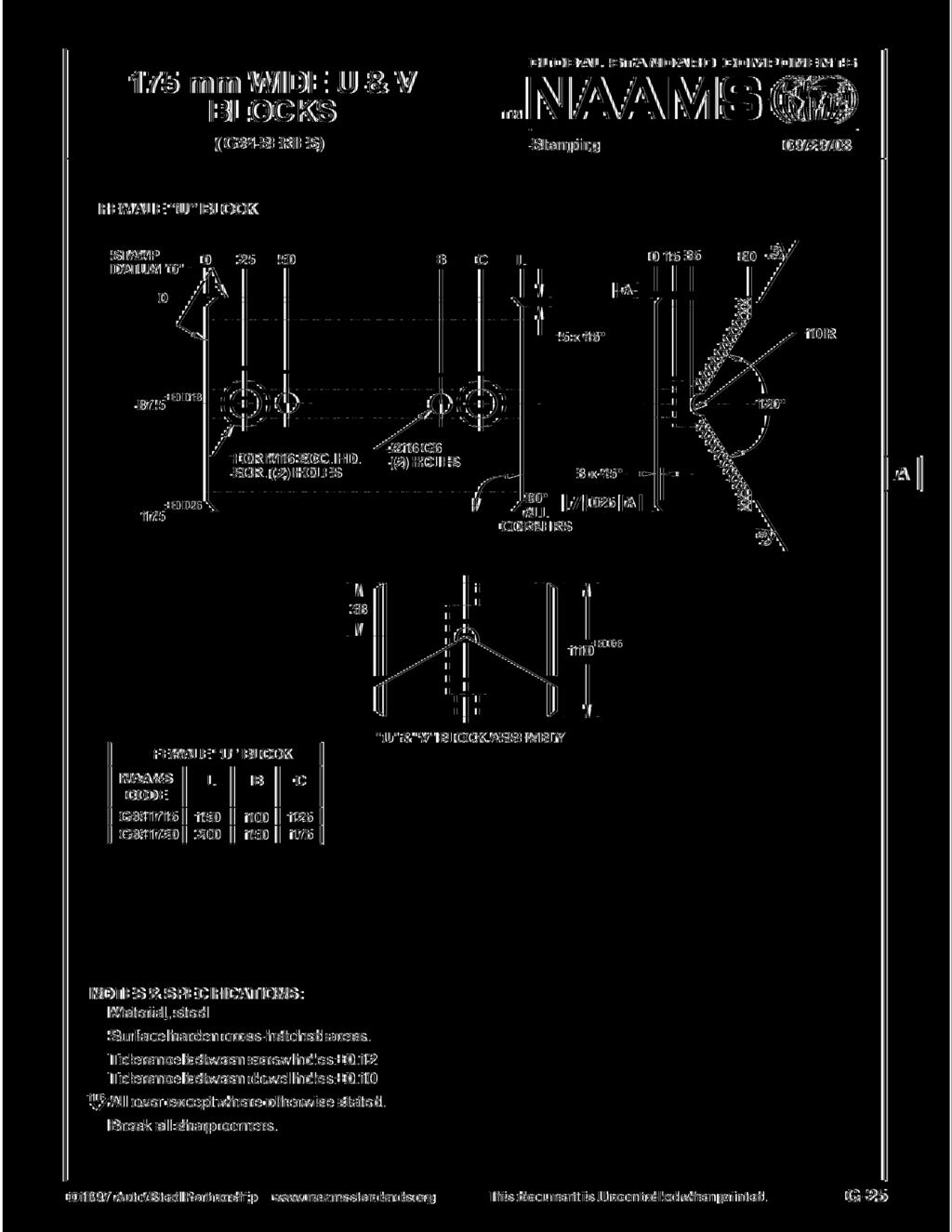
1 GUIDE ND GGE COMPONENTS INDEX 09/16/17 PGE DTE SERIES DESCRIPTION G-1 04/22/14 Guide and Gage Components Index G /22/14 Guide and Gage Components Index G-2 08/12/97 G01 & G02 Self-Lube Guide lock G-3 01/03/95 G01 Self-Lube Guide lock (45mm) Coding G-4 01/03/95 G02 Self-Lube Guide lock (60mm) Coding G-5 08/12/97 G11 Self-Lube Corner Guide locks G-6 05/19/00 Discontinued 65 mm Wide U & V locks G-7 05/19/00 Discontinued 65 mm Wide U & V locks G-8 05/19/00 Discontinued 75 mm Wide U & V locks G-9 05/19/00 Discontinued 75 mm Wide U & V locks G-10 06/20/03 Discontinued 125 mm Wide U & V locks G-11 05/19/00 Discontinued 125 mm Wide U & V locks G-12 05/19/00 G41, G42 & G43 Center Key Guide and Center Key G-13 05/19/00 G50 Shoulder Guide Post/Pin G-14 05/19/00 G50 Shoulder Guide Post/Pin Coding G-15 05/19/00 G51 Guide Post/Pin G-16 10/17/05 G51 Guide Post/Pin Coding G-17 08/04/05 G61 Guide Post/Pin ronze ushing G-18 08/04/05 G71 ronze Pad ushing G-19 04/14/15 Discontinued ushing Toe Clamp G-20 08/09/17 G72 & G73 ushing Clamping Procedures G-21 05/19/00 G81 Finger Gage G-22 05/19/00 Discontinued alancing Cones G-23 05/19/00 Discontinued alancing Cones Coding G-24 10/19/01 G82 Disappearing Gage G-25 04/14/15 Discontinued 175 mm Wide U & V locks G-26 04/14/15 Discontinued 175 mm Wide U & V locks G-27 12/19/12 lank Page 2017 USCR This document is Uncontrolled when printed. G-1
2 GUIDE ND GGE COMPONENTS INDEX GLOL STNDRD COMPONENTS NMS 09/16/17 PGE DTE SERIES DESCRIPTION 04/23/14 04/23/14 04/23/14 04/23/14 06/13/17 04/14/15 G97 G98 G99 G100 Discontinued G mm V lock 65 mm U lock 125 mm V lock 125 mm U lock Guide Pin ushing Toe Clamps alancing Cones 2017 USCR This document is uncontrolled when printed. G-1.1
3 GUIDE ND GGE COMPONENTS INDEX GLOL STNDRD COMPONENTS NMS 09/16/17 PGE DTE SERIES DESCRIPTION 04/14/15 G103 alancing Cone Shim & Coding G104 G104 G104 G104 06/10/17 G104 G105 G105 G105 G105 G-65 06/24/17 G105 G-66 06/25/17 G G-67 06/25/17 G G-68 06/25/17 G G-69 06/25/17 G G-70 06/25/17 G USCR This document is uncontrolled when printed. G-1.2
4 SELF-LUE GUIDE LOCKS (G01 & G02 SERIES) GLOL STNDRD COMPONENTS 08/12/97 L H 0 13 C J 0 E F 0.8 W 12 G6 (2) HOLES FOR M12 SOC. HD. SCR. (N) HOLES D GRPHITE PLUGS THIS SURFCE NOTES & SPECIFICTIONS: Screw hole locations ±0.25 Dowel hole locations ±0.10 reak all sharp edges 0.4 x 45 Material, steel. Surface harden cross-hatched areas. Evenly distributed graphite plugs to cover 20-30% of the area that requires lubrication. CODING ON FOLLOWING PGE 1997 uto/steel Partnership This document is Uncontrolled when printed. G 2
5 SELF-LUE GUIDE LOCK CODING GLOL STNDRD COMPONENTS (G01 SERIES) 01/03/95 45 mm WIDE NMS (N) CODE HOLES L C D E F H J W G G G G G G G G G G G G G G G G G G G G G G G G G G G G G G G G G G G G G G G G CODING CONTINUED ON FOLLOWING PGE 1997 uto/steel Partnership This document is Uncontrolled when printed. G 3
6 SELF-LUE GUIDE LOCK CODING (G02 SERIES) GLOL STNDRD COMPONENTS 01/03/95 60 mm WIDE NMS (N) CODE HOLES L C D E F H J W G G G G G G G G G G G G G G G G G G G G G G G G G G G G G G G G uto/steel Partnership This document is Uncontrolled when printed. G 4
7 SELF-LUE CORNER GUIDE LOCKS GLOL STNDRD COMPONENTS (G11 SERIES) 08/12/97 FOR M16 SOC. HD. SCR. (2) HOLES G6 (2) HOLES L D H 25 C L x 45 CHMFER 32 REK LL SHRP EDGES 0.4 x 45 EXCEPT S SHOWN SURFCE HRDEN & GRPHITE PLUG CROSS-HTCHED RES NMS CODE H C D L G G G G G G G G G NOTES & SPECIFICTIONS: Screw hole locations ±0.25 Dowel hole locations ±0.10 Material, steel. Grind as shown. Evenly distributed graphite plugs to cover 20 30% of the area that requires lubrication uto/steel Partnership This document is Uncontrolled when printed. G 5
8 65 mm WIDE U & V LOCKS GLOL STNDRD COMPONENTS (G15 SERIES) 05/19/00 FEMLE U LOCK SP DTUM "0" ±0.013 ± G6 & 16 C'ORE (2) HOLES FEMLE U LOCK NMS L C N CODE G G G G C L FOR M12 SOC. HD. SCR. (N) HOLES 23 5 x LL CORNERS 65 ±0.05 TYPICL SECTION "U" & "V" LOCK SSEMLY 3 x 45 DISCONTINUED XXXXXX XXXXXX R NOTES & SPECIFICTIONS: Material, steel 1.6 Surface harden cross-hatched areas. Tolerance between screw holes ±0.12 Tolerance between dowel holes ±0.10 ll over except where otherwise stated. reak all sharp corners uto/steel Partnership This document is Uncontrolled when printed. G 6
9 65 mm WIDE U & V LOCKS GLOL STNDRD COMPONENTS (G16 & G17 SERIES) 05/19/00 MLE V LOCK MLE V LOCK NMS NMS L C N CODE(X) CODE(Y) G G G G G G G G NOTES & SPECIFICTIONS: Material, steel or bronze 1.6 SP DTUM "0" 0 Use code X for steel Use code Y for bronze DISCONTINUED Surface harden cross-hatched areas on steel. Tolerance between screw holes ±0.12 Tolerance between dowel holes ±0.10 ll over except where otherwise stated. reak all sharp corners 0 ± ± G6 (2) HOLES 50 FOR M12 SOC. HD. SCR. (N) HOLES C Male V driver requires evenly distributed graphite plugs to cover 20-30% of the surface that requires lubrication L 5 x LL CORNERS TYPICL SECTION "U" & "V" LOCK SSEMLY ± GRPHITE PLUGS THESE SURFCES ON MLE DRIVE ONLY x uto/steel Partnership This document is Uncontrolled when printed. G 7
10 75 mm WIDE U & V LOCKS (G21 SERIES) GLOL STNDRD COMPONENTS 05/19/00 FEMLE U LOCK SP DTUM "0" 12 G6 & 16 C'ORE (2) HOLES C L ±0.013 ±0.026 FEMLE U LOCK NMS L C N CODE G G G G FOR M12 SOC. HD. SCR. (N) HOLES 23 5 x LL CORNERS 65 ±0.05 TYPICL SECTION "U" & "V" LOCK SSEMLY x 45 DISCONTINUED -- XXXXXX XXXXXX R NOTES & SPECIFICTIONS: Material, steel Surface harden cross-hatched areas. 1.6 Tolerance between screw holes ±0.12 Tolerance between dowel holes ±0.10 ll over except where otherwise stated. reak all sharp corners uto/steel Partnership This document is Uncontrolled when printed. G 8
11 XXXXX XXXX XXXXXX 75 mm WIDE U & V LOCKS (G22 & G23 SERIES) GLOL STNDRD COMPONENTS 05/19/00 MLE V LOCK SP DTUM "0" 0 25 NOTES & SPECIFICTIONS: Material, steel or bronze Use code X for steel Use code Y for bronze DISCONTINUED Surface harden cross-hatched areas on steel. Tolerance between screw holes ±0.12 Tolerance between dowel holes ±0.10 ll over except where otherwise stated. reak all sharp corners 0 ± ± G6 (2) HOLES 50 FOR M12 SOC. HD. SCR. (N) HOLES MLE V LOCK NMS NMS L C N CODE(X) CODE(Y) G G G G G G G G C Male V driver requires evenly distributed graphite plugs to cover 20-30% of the surface that requires lubrication L 5 x LL CORNERS ±0.05 TYPICL SECTION "U" & "V" LOCK SSEMLY 42 GRPHITE PLUGS THESE SURFCES ON MLE DRIVE ONLY x uto/steel Partnership This document is Uncontrolled when printed. G 9

12 DISCONTINUED DISCONTINUED
13 125 mm WIDE U & V LOCKS (G32 & G33 SERIES) GLOL STNDRD COMPONENTS 05/19/00 MLE V LOCK MLE V LOCK NMS NMS L C N CODE(X) CODE(Y) G G G G G G G G NOTES & SPECIFICTIONS: Material, steel or bronze 1.6 SP DTUM "0" ± Use code X for steel Use code Y for bronze "U" & "V" LOCK SSEMLY 85 ±0.05 DISCONTINUED Surface harden cross-hatched areas on steel. Tolerance between screw holes ±0.12 Tolerance between dowel holes ±0.10 ll over except where otherwise stated. reak all sharp corners GRPHITE PLUGS THESE SURFCES ON MLE DRIVE ONLY G6 FOR M16 SOC. HD. (2) HOLES SCR. (N) HOLES 17.5 C'ORE DEEP ± LL CORNERS 5 x 45 3 x 45 Male V driver requires evenly distributed graphite plugs to cover 20 30% of the surface that requires lubrication C L XXXXX XXXX XXXXXXXXXX X X X XXXX uto/steel Partnership This document is Uncontrolled when printed. G 11
14 CENTER KEY GUIDE ND CENTER KEY (G41, G42 & G43 SERIES) GLOL STNDRD COMPONENTS 05/19/00 CENTER KEY GUIDE (G41) C 12 G6 (2) HOLES D CENTER KEY (G42 & G43) C 12 G6 (2) HOLES D L M12 x 1.75 TP PULLOUT HOLE (2) HOLES L M12 X 1.75 TP PULLOUT HOLE (2) HOLES FOR M12 SOC HD. SCR. N HOLES 50 FOR M12 SOC HD. SCR. N HOLES x DOWEL 0 CENTRL x DOWEL CENTRL GRPHITE PLUG THESE SURFCES x R CENT LUE RE NMS NMS CODE(X) CODE (Y) C D L N G G G G G G Use Code X for steel, Code Y for bronze. NOTES & SPECIFICTIONS: Tolerance between screw holes ±0.25 Tolerance between dowel holes ±0.10 Material, steel or bronze. Surface harden cross-hatched areas on steel. Evenly distributed graphite plugs to cover 20-30% of the area that requires lubrication uto/steel Partnership This document is Uncontrolled when printed. G 12
15 SHOULDER GUIDE POST/PIN (G50 SERIES) GLOL STNDRD COMPONENTS 05/19/00 4 TO 6 LED (R20 OPTIONL) 2 LED LENGTH 32, 40, 50, & 63 DI. GUIDE POSTS TO HVE M8 x LONG THRED; 80, 100, & 115 DI. GUIDE POSTS TO HVE M12 x LONG THRED TO FCILITTE HNDLING FROM DEEP FREEZE R1 6 CIRCLE X D1 g6 D3 D2 r6 15 L3 L2 R1 CENTER DRILL, OTH ENDS TO MNUFCTURER'S CHOICE L1 6 4 D2 r6 D2 h6 R1 5 VIEW IN CIRCLE X 1997 uto/steel Partnership This document is Uncontrolled when printed. G 13
16 SHOULDER GUIDE POST/PIN CODING (G50 SERIES) GLOL STNDRD COMPONENTS 05/19/00 NMS CODE D1 D2 D3 L1 L2 L3 R1 G G G G G G G G G G G G G G G G G G G G G G G G G G G uto/steel Partnership This document is Uncontrolled when printed. G 14
17 GUIDE POST/PIN GLOL STNDRD COMPONENTS (G51 SERIES) 05/19/00 4 TO 6 LED (R20 OPTIONL) 2 LED LENGTH 32, 40, 50, & 63 DI. GUIDE POSTS TO HVE M8 x LONG THRED; 80, 100, & 115 DI. GUIDE POSTS TO HVE M12 x LONG THRED TO FCILITTE HNDLING FROM DEEP FREEZE R CIRCLE X D2 r6 D1 g6 15 L3 L1 0.5R R1 L2 CENTER DRILL, OTH ENDS TO MNUFCTURER'S CHOICE D2 r6 D2 h6 R1 5 D2 r6 R1 3 /4 VIEW IN CIRCLE X VIEW IN CIRCLE X OPTIONL CONSTRUCTION NOTES & SPECIFICTIONS: Hardened steel CODING ON FOLLOWING PGE 1997 uto/steel Partnership This document is Uncontrolled when printed. G 15
18 GUIDE POST/PIN CODING ( G51 SERIES) 10/17/05 NMS CODE D1 D2 L1 L2 L3 R1 G G G G G G G G G G G G G G G G G G G G G G G G G G G G G G G G G G G G G G G G G G G G G G G G G G G uto/steel Partnership This document is Uncontrolled when printed. G-16 C D
19 GUIDE POST/PIN RONZE USHING (G61 SERIES) S tamping 04/10/ L R 1 ØD1 H6 ØD3 ØD4 ØD2 g6 2R Ø0.02 C 6.3 L2 L1 NMS CODE G D1 25 D2 32 D3 40 D4 32 L1 40 L2 30 L3 4 R1 3 G G G G G G G G NOTES & SPECIFICTIONS: Order bus hing clamps s eparately. E venly distributed graphite to cover 20-30% of the sliding surface. G raphite to be positioned to insure overlapping in the slide direction. D 1997 uto/s teel P a rtners hip www. na a ms s ta nda rds. org T his document is U ncontrolled when printed. G -17

20 RONZE PD USHING (G71 SERIES) S tamping 04/10/ L C 9 ØD1 ØD3 ØD2g R -- Ø C L1 NMS CODE G G D D D L L2 4 4 G G G G G G NOTES & SPECIFICTIONS: Order bus hing clamps s eparately. E venly distributed graphite to cover 20-30% of the sliding surface. G raphite to be positioned to insure overlapping in the slide direction. D 1997 uto/s teel P a rtners hip www. na a ms s ta nda rds. org T his document is U ncontrolled when printed. G -18
21 USHING TOE CLMP (G72 ND G73 SERIES) US HING C E NTE R DISCONTINUED NMS C ODE G M 0.4R N 6 S tamping 04/10/15 D C NMS C ODE G = 24.6 = 18.9 C = 13 D = M8 x 1.25 x 20 = 27.9 = 23.5 C = 15.5 D = M10 x 1.5 x 20 NOM POST DI M N NOM POST DI M N NOTES & SPECIFICTIONS: Each clamp must withstand 10,000 newtons pull 1997 uto/s teel P a rtners hip www. na a ms s ta nda rds. org T his document is U ncontrolled when printed. G -19
22 USHING CLMPING PROCEDURES (G72 and G73 SERIES) G L O L S T NDRD COMPO NENT S 08/09/17 D3 (O.D. OF US HING S HOULDE R ) D1 ( I.D. OF US HING ) US HING C L MP TP (2) HOLE S E QULLY S PC E D.C. = M8 x 1.25 (USE 1 CLMP PER USHING) D1 D3.C. (D3+18) = M10 x 1.25 (USE 2 CLMPS PER USHING) D1 D3.C. (D3+21) NOTES & SPECIFICTIONS: Order bushing clamps separately. Screws must engage 16 mm minimum deep into die shoe for M8 screws and 20mm minimum for M10 screws. Each clamp must withstand 10,000 newtons pull. ushing clamp styles vary per OEM user USCR This document is Uncontrolled when printed. G 20 C
23 FINGER GGE (G81 SERIES) GLOL STNDRD COMPONENTS 05/19/ SLOT IN CSTING 13 LENDED R 5 20 R20 H R Ø30 NOTES & SPECIFICTIONS: Material, steel NMS CODE H G G G G G G uto/steel Partnership This document is Uncontrolled when printed. G 21
24 LNCING CONES (G91 SERIES) G L O L S T N D R D C O M P O NEN T S SSEMLY INCLUDES 5.5 THICK SHIM PLTE 05/19/00 UPPER CONE LOWER CONE LOWER CONE UPPER CONE M12x1.75 Ø11 Ø0.4 L H Ø0.02 L L C 90 ±5' Ø16 H7 15 C (REF) F G Ø11 Ø0.4 L Ø0.02 L L ±5' DISCONTINUED C E Ø16 H7 J C (REF) K CODING ON FOLLOWING PGE NOTES & SPECIFICTIONS: Material: steel, case harden to Rc uto/steel Partnership This document is Uncontrolled when printed. G 22
25 LNCING CONES (G91 SERIES) G L O L S T NDRD COMPO NENT S 05/19/00 SSEMLY INCLUDES 5.5 THICK SHIM PLTE UPPER CONE L LOWER CONE CONE C E F G H J K L CONTCT SURFCE 100 LOWER mm 2 UPPER LOWER mm 2 UPPER NMS CODE* L DISCONTINUED G G * ssembly consisting of 1 shim plate, 1 upper cone and, 1 lower cone 1997 uto/steel Partnership This document is Uncontrolled when printed. G 23
26 DISPPERING GGE (G82 SERIES) GLOL STNDRD COMPONENTS 10/19/ COUPLING PLTE NUT FOR M10 SOC. HD. SCREW (4) HOLES FOR M8 SOC. HD. SCREW (2) HOLES C UP TO 100 STROKE 20 IR CYLINDER FRONT FLNGE MOUNT 40mm ORE NOT INCLUDED IN SSEMLY NMS CODE G G G G SLIDE TRVEL UP TO ND C uto/steel Partnership This document is Uncontrolled when printed. G 24
27 DISCONTINUED 04/14/15

28 DISCONTINUED 04/14/15
29 lank Page 12/19/12 Data Removed. Pages Left lank For Future Use uto/steel Partnership This document is Uncontrolled when printed. G-27
30 lank Page 12/19/12 Data Removed. Pages Left lank For Future Use uto/steel Partnership This document is Uncontrolled when printed. G-28
31 lank Page 12/19/12 Data Removed. Pages Left lank For Future Use uto/steel Partnership This document is Uncontrolled when printed. G-29
32 lank Page 12/19/12 Data Removed. Pages Left lank For Future Use uto/steel Partnership This document is Uncontrolled when printed. G-30
33 lank Page 12/19/12 Data Removed. Pages Left lank For Future Use uto/steel Partnership This document is Uncontrolled when printed. G-31
34 lank Page 12/19/12 Data Removed. Pages Left lank For Future Use uto/steel Partnership This document is Uncontrolled when printed. G-32
35 lank Page 12/19/12 Data Removed. Pages Left lank For Future Use uto/steel Partnership This document is Uncontrolled when printed. G-33
36 lank Page 01/29/13 Data Removed. Pages Left lank For Future Use uto/steel Partnership This document is Uncontrolled when printed. G-34
37 lank Page 01/29/13 Data Removed. Pages Left lank For Future Use uto/steel Partnership This document is Uncontrolled when printed. G-35
38 LNK CROWDER (G56 SERIES) T M S tamping 08/01/ ±0.01 G 1/8" P OR T S 2 - P LC E S ± Ø10 H7 DOW E LS 2-P LC E S Ø11 THROUGH 4-P LC E S 48 H (S T R OK E ) S C ODING ON F OLLOW ING PG E NOTES & SPECIFICTIONS: ir cylinder may be rotated 90 CW or CCW for horizontal ports uto/s teel P artners hip T his document is Uncontrolled when printed. G -36
39 LNK CROWDER (G56 SERIES) 08/01/11 NMS Code H STROKE S G G G G G G G G G G G G G G G G G G uto/s teel P artners hip T his document is Uncontrolled when printed. G -37
40 LNK PGE 08/01/11 Data Removed. Pages Left lank For Future Use uto/steel Partnership This document is Uncontrolled when printed. G-38
41 LNK PGE 08/01/11 Data Removed. Pages Left lank For Future Use uto/steel Partnership This document is Uncontrolled when printed. G-39
42 TRIM T PILOT GGE (G95 SERIES) 08/01/11 DETIL DESCRIPTION 1 PILOT PIN GGE 2 TRIM LDE 3 GGE LOCK 4 PILOT GGE SE 5 GGE LOCK DJUSENT SCREW NMS CODE H PIN HEIGHT TRIM LDE STEEL PIN DIMETER G YES G YES G95150C NO G95300D NO G95150E NO PIN YES G95300F NO PIN NO G95150G YES G95300H YES G95150J NO G95150K NO PIN YES G95300L NO G95150M YES G95300N YES G95150P NO G95300R NO G95150S NO PIN YES H 30 5 CONTINUED ON FOLLOWING PGES NOTES & SPECIFICTIONS: MTERIL : SEE ECH DETIL FOR MTERIL 1997 uto/steel Partnership This document is Uncontrolled when printed. G-40
43 TRIM T PILOT GGE (G95 SERIES) 08/01/ R H Ø +0 Ø NMS CODE Ø H G G G G G G Ø 23 1 PILOT PIN GGE NOTES & SPECIFICTIONS: MTERIL : ISO CrMoV15-1 HRDEN Rc DOULE TEMPER 1997 uto/steel Partnership This document is Uncontrolled when printed. G-41
44 TRIM T PILOT GGE (G95 SERIES) 08/01/ NMS Code Dim. G G G Pilot Required ±0.05 FOR M12 SOCKET HED SCREW 2 PLCES DRILL ND REM FOR Ø12 DOWEL 2 PLCES Ø20 MCHINE T SSEMLY Ø TRIM LDE NOTES & SPECIFICTIONS: MTERIL : ISO CrMoV15-1 LEFT SOFT FINISH SSEMLY 1997 uto/steel Partnership This document is Uncontrolled when printed. G-42
45 TRIM T PILOT GGE (G95 SERIES) 08/01/11 8 x Ø Ø 24 3 GGE LOCK NOTES & SPECIFICTIONS: MTERIL : ISO 683/18 - C uto/steel Partnership This document is Uncontrolled when printed. G-43
46 TRIM T PILOT GGE (G95 SERIES) 08/01/11 DRILL ND REM FOR Ø 12 DOWEL 2 PLCES M12x1 TP 35 DEEP 2 PLCES DRILL ND REM FOR Ø 6 DOWEL DRILL ND REM FOR Ø 12 DOWEL 2 PLCES FOR M12 SOCKET HED SCREW 4 PLCES Ø Ø 13.5 M20x2.5 TP THROUGH 4 PILOT GGE SE NOTES & SPECIFICTIONS: MTERIL : ISO 683/18 - C uto/steel Partnership This document is Uncontrolled when printed. G-44
47 TRIM T PILOT GGE (G95 SERIES) 08/01/ CHMFER (2 PLCES) M20 x 2.5 JM NUT M20 x 2.5 THRED HEX SOCKET 10 x 10 DEEP 5 GGE LOCK DJUSENT SCREW NOTES & SPECIFICTIONS: MTERIL :. ISO 683/18 - C18-7 THREDED ROD -OR- ISO (min). ISO 683/18 - C uto/steel Partnership This document is Uncontrolled when printed. G-45
48 200MM DJUSTLE LNK GGE WITH R SENSOR G96 SERIES 12/19/12 G or J 5 SENSING RNGE NMS CODE ND MFG. IDENTIFICTION HERE C D 120 COMMERCIL ELECTRICL EXTENSION CLE H E 5 F 8 70 T MX HEIGHT 20 T MIN HEIGHT NMS CODE G G NMS Code - G VDC Sensor NMS Code - G VC Sensor ITEM I.D. QUNTITY DESCRIPTION OF DJUSTLE LNK GGE WITH R SENSOR KIT 1 - R SENSOR - 24VDC TURCK #I20-CK40130-VP4X2-H1141/S1009 OR EQUIVLENT 8 8 M6 FLTWSHER C 2 2 M6 x 0.8 LOCKNUT WITH NYLON INSERT D 4 4 M6 x 0.8 x 12 UTTON HED CP SCREW (LUE) E 1 1 GENERIC M6 NYLON TUING CLIP F 1 1 M6 x 0.8 x 8 LONG SOCKET HED CP SCREW G 1 1 GGE RISER RCKET H 1 1 SENSOR MOUNT RCKET J - 1 R SENSOR - 120VC TURCK #I20-CK40130-DZ30X2-1131/S1009 OR EQUIVLENT NOTES & SPECIFICTIONS: djustable 200mm blank gage with 130mm bar sensor. Mark with NMS code in 6mm high letters as shown, and manufacturers identification. Install with M10 x 30 long socket head cap screws, M10 flat washers and lock washer. (Not suppiled.) Tack weld washers to base after final adjustment. For flat binders, ottom of sensor must be 5mm below edge of nested blank uto/steel Partnership This document is Uncontrolled when printed. G-46
49 200MM DJUSTLE LNK GGE WITH R SENSOR G96 SERIES 12/19/12 R5.5 TYP. R5.5 TYP. M6 x 1.0 TP THRU 10 DETIL G GGE RISER RCKET G or G x 25 x 44 CRS PLTE INSET 2mm HRDEN RCES TO RC45-50/.015DP PRIOR TO WELDING M6 x 1.0 TP (8) PLCES OTH SIDES 10 TYP NOTES & SPECIFICTIONS: MTERIL: ISO 683/18 - C20 (LCK OXIDE FINISH) 1997 uto/steel Partnership This document is Uncontrolled when printed. G-47
50 W W 200MM DJUSTLE LNK GGE WITH R SENSOR G96 SERIES 12/19/12 DETIL H SENSOR MOUNT RCKET G or G W R3.25 TYP W NOTES & SPECIFICTIONS: Material: ISO 683/18 - C20 (lack Oxide Finish) 1997 uto/steel Partnership This document is Uncontrolled when printed. G-48
51 65 mm WIDE V LOCK GLOL STNDRD COMPONENTS (G97 SERIES) 04/23/14 MLE V LOCK SP DTUM "0" 0 25 Ø 12 H7 (2) HOLES ± C L 5 x GRPHITE PLUGS THESE SURFCES ON MLE DRIVE ONLY ± ± FOR M12 SOC. HD. SCR. (N) HOLES 90 LL CORNERS x ±0.05 MLE V LOCK NMS L C N CODE ±0.2 ±0.2 ±0.2 G G G G NOTES & SPECIFICTIONS: Material, ISO-CuZn25I5 Tolerance between screw holes ±0.12 Tolerance between dowel holes ± ll over except where otherwise stated. reak all sharp corners TYPICL SECTION "U" & "V" LOCK SSEMLY Male V driver requires evenly distributed graphite plugs to cover 20-30% of the surface that requires lubrication 2017 USCR This document is Uncontrolled when printed. G 49
52 65 mm WIDE U LOCK GLOL STNDRD COMPONENTS (G98 SERIES) 04/23/14 FEMLE U LOCK SP DTUM "0" Ø12 H7 C'ORE (2) HOLES 0 ± C L ± x XXXXXX R 65 ±0.026 FOR M12 SOC. HD. SCR. (N) HOLES 90 LL CORNERS x 45 XXXXXX ±0.05 TYPICL SECTION "U" & "V" LOCK SSEMLY FEMLE U LOCK NMS L C N CODE ±0.2 ±0.2 ± G G G G NOTES & SPECIFICTIONS: Material, ISO 683/1 42CrMo4 1.6 Surface harden cross-hatched areas. Tolerance between screw holes ±0.12 Tolerance between dowel holes ±0.10 ll over except where otherwise stated. reak all sharp corners USCR This document is Uncontrolled when printed. G 50
53 125 mm WIDE V LOCK (G99 SERIES) GLOL STNDRD COMPONENTS 04/23/14 MLE V LOCK SP DTUM "0" ± ±0.02 C L GRPHITE PLUGS THESE SURFCES ON MLE DRIVE ONLY Ø 16 H7 FOR M16 SOC. HD. (2) HOLES SCR. (N) HOLES 17.5 C'ORE DEEP ± LL CORNERS 5 x 45 3 x XXXXX XXXX XXXXXXXXXX X X X XXXX ±0.05 MLE V LOCK NMS L C N CODE ±0.2 ±0.2 ± G G G G "U" & "V" LOCK SSEMLY NOTES & SPECIFICTIONS: Material, ISO-CuZn25l5 1.6 Tolerance between screw holes ±0.12 Tolerance between dowel holes ±0.10 ll over except where otherwise stated. reak all sharp corners Male V driver requires evenly distributed graphite plugs to cover 20 30% of the surface that requires lubrication 2017 USCR This document is Uncontrolled when printed. G 51
54 125 mm WIDE U LOCK (G100 SERIES) 04/23/14 55 ±0.02 H7 FEMLE U LOCK NMS L C N CODE ±0.2 ±0.2 ± G G G G ISO 683/1 42CrMo USCR This document is Uncontrolled when printed. G-52
55 GUIDE PIN USHING TOE CLMPS (G101 & G102 SERIES) 06/13/17 NMS CODE G G J ØF D C USHING C E F G H J K CLMPS I.D. h9 D REQUIRED DISCONTINUED ØE H 6.3 K G NOTES & SPECIFICTIONS: Material: steel. reak all sharp edges. Mark with NMS Code and manufacturers identification. Each clamp must withstand 10,000 newtons pull uto/steel Partnership This document is Uncontrolled when printed. G-53
56 LNCING CONES (G103 SERIES) S tamping 04/14/15 UP P E R C ONE L OWE R C ONE L OWE R C ONE S S E M LY INC LUDE S 5.5 THIC K S HIM P LTE UP P E R C ONE M12x C (R E F) (R E F) C Ø11 Ø0.4 L Ø11 Ø0.4 L M12 Ø Ø0.02 L L Ø16 H7 15 H Ø12 Ø0.02 L L ±5 Ø16 H F G 90 ±5 C E 1.25 J -- K C C C ODING ON FOLLOWING PG E NOTES & SPECIFICTIONS: Material: steel, case harden to Rc uto/s teel P artnership T his document is Uncontrolled when printed. G 54
57 LNCING CONE SHIM & CODING (G103 SERIES) S tamping 04/14/15 UP P E R C ONE L L OWE R C ONE S S E M LY INC LUDE S 5.5 THIC K S HIM P LTE (OR DE R E D S 6.0 THIC K ) CONE C E F G H J K L CONTCT SURFCE 100 LOWER UPPER mm LOWER UPPER mm 2 C NMS CODE* G L G d 2 d 1 30 d 3 * ssembly consisting of 1 shim plate, 1 upper cone and, 1 lower cone C 6.0 d1 d2 d Ø11 Ø18 S E C TION C -C NOTES & SPECIFICTIONS: Solid model library part is 5.5 mm thick. ctual component to be purchased at 6.0 mm thickness. (For sizing at tryout.) 1997 uto/s teel P artnership T his document is Uncontrolled when printed. G 55
58 Ø50 HD GUIDE KEEPER (G104 Series) GLOL STNDRD COMPONENTS NMS 06/10/17 10 MIN. PD TRVEL D URETHNE DMPENER USHING GUIDE PIN 5 MIN. NMS CODE G G G G G G G G G G PIN LENGTH PD TRVEL DIE SHOE PIN LENGTH ERING SSEMLY M12 x LONG MINIMUM E 10 MINIMUM 20 PREFERRED PRESSURE PD COLLR C M16 x LONG DET. C D E QUN DESCRIPTION GUIDE PIN URETHNE DMPENER COLLR USHING ERING SSEMLY NOTES & SPECIFICTIONS: MTERIL: STEEL - MNUFCTURERS CHOICE reak all edges. Mark with NMS order code and manufacturer s logo. Refer to manufactures catalog for design information. For use in upper and lower pads USCR This document is uncontrolled when printed. G-56
59 Ø50 HD GUIDE KEEPER (G104 Series) GLOL STNDRD COMPONENTS NMS 06/10/17 Ø105 Ø50 REF REF. CLERNCE HOLE FOR M12 SHCS (8) PLCES EQULLY SPCED ON 86.0 OLT CIRCLE Ø70 f7 DETIL D - USHING MTERIL: STEEL (MNUFCTURERS CHOICE) 8 - M12 x 1.75 x 40 long grade 12.9 socket head cap screws required for assembly (not supplied) USCR This document is uncontrolled when printed. G-57
60 Ø50 HD GUIDE KEEPER (G104 Series) GLOL STNDRD COMPONENTS NMS 06/10/ M TP x 40 DEEP (3) HOLES EQULLY SPCED ON OLT CIRCLE RETENTION COLLR Ø50 f7 PIN LENGTHS Ø69.5 DETIL - GUIDE PIN MTERIL: STEEL (MNUFCTURERS CHOICE) For a 75mm thick steel pad, 3 - M16 x 2.0 x 70 long grade 12.9 socket head cap screws required for assembly (not supplied) USCR This document is uncontrolled when printed. G-58
61 Ø50 HD GUIDE KEEPER (G104 Series) GLOL STNDRD COMPONENTS NMS 06/10/17 DRILLED ND COUNTERORED FOR M16 SHCS - (3) PLCES EQULLY SPCED ON Ø30.48 OLT CIRCLE REF Ø57.2 O RING DETIL C - COLLR M T E R I L : S T E E L (M N U F C T U R E R S C H O IC E ) 2017 USCR This document is uncontrolled when printed. G-59
62 Ø50 HD GUIDE KEEPER (G104 Series) GLOL STNDRD COMPONENTS NMS 06/10/17 Ø Ø ORE Ø18 DRILL THROUGH (3) EQULLY SPCED ON Ø30.48 OLT CIRCLE 36 MIN 45 MIN Ø70.0 H INSTLL GUIDE PIN HERE 75 REF INSTLL COLLR HERE REF FOR CST PDS 40 MINIMUM FOR CST PDS Ø58 ±0.05 ORE 43 REF M12 x 1.75 TP 36 DEEP (8) PLCES EQULLY SPCED ON 86.0 OLT CIRCLE (45 DEEP TP DRILL HOLE - DRILL THROUGH PERMITTED) DIE SHOE MCHINING FOR DETIL PD MCHINING FOR DETILS ND C NOTES & SPECIFICTIONS: In s ta lla tio n in fo rm a tio n S e rra te d s a fe ty w a s h e rs a re re c o m m e n d e d USCR This document is uncontrolled when printed. G-60
63 Ø36 HD GUIDE KEEPER (G105 Series) GLOL STNDRD COMPONENTS NMS 06/24/17 URETHNE DMPENER 10 MIN. DET. C D E QUN DESCRIPTION GUIDE PIN URETHNE DMPENER COLLR USHING ERING SSEMLY PD TRVEL GUIDE PIN 5 MIN. Ø36 REF. ERING E SSEMLY D USHING PIN LENGTH DIE SHOE M12 x LONG 5 MINIMUM 15 PREFERRED PRESSURE PD COLLR C M12 x LONG NOTES & SPECIFICTIONS: MTERIL: STEEL - MNUFCTURERS CHOICE NMS CODE G G G G G G G G G G PIN LENGTH PD TRVEL reak all edges. Mark with NMS order code and manufacturer s logo. Refer to manufactures catalog for design information. For use in small upper pads with engineering approval only. For use in lower pads when G98 series guide keepers will not fit USCR This document is uncontrolled when printed. G-61
64 Ø36 HD GUIDE KEEPER (G105 Series) GLOL STNDRD COMPONENTS NMS 06/24/ CLERNCE HOLE FOR M12 SHCS (4) PLCES Ø36.0 REF Ø50 f7 DETIL - USHING MTERIL: STEEL (MNUFCTURERS CHOICE) 6 - M12 x 1.75 x 30 long grade 12.9 socket head cap screws required for assembly (not supplied) USCR This document is uncontrolled when printed. G-62
65 Ø36 HD GUIDE KEEPER (G105 Series) GLOL STNDRD COMPONENTS NMS 06/24/ M TP x 23 DEEP (4) HOLES EQULLY SPCED ON 23.0 OLT CIRCLE 15 C ORE RETENTION COLLR 10 Ø36.0 f PIN LENGTHS DMPENING WSHER Ø DETIL - GUIDE PIN MTERIL: STEEL (MNUFCTURERS CHOICE) For a 75 mm thick steel pad, 3 - M12 x 1.75 x 50 long grade 12.9 socket head cap screws required for assembly (not supplied) USCR This document is uncontrolled when printed. G-63
66 Ø36 HD GUIDE KEEPER (G105 Series) GLOL STNDRD COMPONENTS NMS 06/24/17 DRILLED ND COUNTERORED FOR M10 SHCS - (4) PLCES EQULLY SPCED ON Ø23.0 OLT CIRCLE 11.5 REF Ø49.0 O RING 20.0 DETIL C - COLLR MTERIL: STEEL (MNUFCTURERS CHOICE) 2017 USCR This document is uncontrolled when printed. G-64
67 Ø36 HD GUIDE KEEPER (G105 Series) GLOL STNDRD COMPONENTS NMS 06/24/17 Ø Ø ORE Ø11.5 DRILL THROUGH (4) EQULLY SPCED ON Ø23.0 OLT CIRCLE 36 MIN 45 MIN REF Ø50.0 H8 ORE 0.25 INSTLL GUIDE PIN HERE REF INSTLL COLLR HERE REF FOR CST PDS 40 MINIMUM FOR CST PDS 15 DIE SHOE MCHINING FOR DETIL M12 x 1.75 TP 36 DEEP (4) PLCES (45 DEEP TP DRILL HOLE MIN. DRILL THROUGH PERMITTED) Ø50.0 ±0.05 ORE PD MCHINING FOR DETILS ND C NOTES & SPECIFICTIONS: Installation information Serrated safety washers recomended USCR This document is uncontrolled when printed. G-65
68 Ø65 HD GUIDE KEEPER (G106 Series) GLOL STNDRD COMPONENTS NMS 06/25/17 10 MIN URETHNE DMPENER 5 MIN. PD TRVEL PIN LENGTH D USHING DIE SHOE GUIDE PIN NMS CODE G G G G G G G G G G PIN LENGTH PD TRVEL M16 x 2 50 LONG ERING SSEMLY E 10 MINIMUM 20 PREFERRED PRESSURE PD COLLR C M16 x 2-70 LONG DET. C D E QUN DESCRIPTION GUIDE PIN URETHNE DMPENER COLLR USHING ERING SSEMLY NOTES & SPECIFICTIONS: MTERIL: STEEL - MNUFCTURERS CHOICE reak all edges. Mark with NMS order code and manufacturer s logo. Refer to manufactures catalog for design information. For use in upper and lower pads USCR This document is uncontrolled when printed. G-66
69 Ø65 HD GUIDE KEEPER (G106 Series) GLOL STNDRD COMPONENTS NMS 06/25/17 20 M TP x 40 DEEP (4) HOLES EQULLY SPCED ON Ø40 OLT CIRCLE RETENTION COLLR Ø65 f7 PIN LENGTHS NOTES & SPECIFICTIONS: Ø89.0 DETIL - GUIDE PIN MTERIL: STEEL (MNUFCTURER S CHOICE) For a 75mm thick steel pad, 3 - M16 x 2.0 x 70 long grade 12.9 socket head cap screws required for assembly (not supplied) USCR This document is uncontrolled when printed. G-67
70 Ø65 HD GUIDE KEEPER (G106 Series) GLOL STNDRD COMPONENTS NMS 06/25/17 DRILLED & C ORED FOR M16 SHCS - (4) PLCES EQULLY SPCED ON Ø40 OLT CIRCLE 20 Ø DETIIL C - COLLR NOTES & SPECIFICTIONS: MTERIL: STEEL (MNUFCTURER S CHOICE) 2017 USCR This document is uncontrolled when printed. G-68
71 Ø65 HD GUIDE KEEPER (G106 Series) GLOL STNDRD COMPONENTS NMS 06/25/17 Ø140 Ø65 REF CLERNCE HOLE FOR M16 SHCS (6) PLCES EQULLY SPCED ON OLT CIRCLE Ø90.0 f7 DETIL D - USHING NOTES & SPECIFICTIONS: MTERIL: STEEL (MNUFCTURER S CHOICE) 6 - M16 x 2.0 x 50 long grade 12.9 socket head cap screws required for assembly (not supplied) USCR This document is uncontrolled when printed. G-69
72 Ø65 HD GUIDE KEEPER (G106 Series) GLOL STNDRD COMPONENTS NMS 06/25/17 Ø18 DRILL THROUGH (4) EQULLY SPCED ON Ø40.0 OLT CIRCLE Ø Ø ORE 47 MIN 60 MIN REF 5 CST OSS Ø90.0 H8 ORE REF FOR HRS PDS INSTLL GUIDE PIN HERE INSTLL COLLR HERE REF FOR CST PDS 40 MINIMUM FOR CST PDS Ø90 ±0.05 ORE REF M16 x 2.0 TP 47 DEEP (DRILL 60 DEEP MIN. - DRILL THROUGH PERMITTED) (6) PLCES EQULLY SPCED ON OLT CIRCLE DIE SHOE MCHINING FOR DETIL PD MCHINING FOR DETILS ND C NOTES & SPECIFICTIONS: Installation information Serrated safety washers are recommended USCR This document is uncontrolled when printed. G-70
MISCELLANEOUS INDEX PAGE DATE SERIES DESCRIPTION
 MISCELLNEOUS INDEX 08/01/11 PGE DTE SERIES DESCRIPTION M-1 08/01/11 Miscellaneous Index M-2 04/16/96 M01 Tooling all M-3 04/16/96 M02 Scrap Chute Hook and Retainer racket M-4 01/03/95 M03 Scrap Chute Chain
Appendix E D791 and T791 Head and Valve Holddown Assembly Details
 Appendix E D nd T Hed nd Vlve Holddown Assemly Detils Hed First Stge Holddown Assemly (") Suction with Unloder Suction (Stndrd) First Stge Holddown Assemly (") Dischrge See figure A 0 CAUTION: Alwys relieve
Series. 777 Oakmont Lane, Westmont, IL Outside U.S
 Oakmont Lane, Westmont, IL 609 1.800..9114 Outside U.S. 1-60-90-6990 www.tksimplex.com G SERIES IR TORQUE PUMP PRTS IDENTIFICTION MNUL Reference # - TD09 Rev. - Date - 8/10 This illustration is for reference
-XC9: Adjustable Stroke Cylinder/Adjustable Retraction Type
 -XC: djustle Stroke Cylinder/djustle etrction Type djustle Stroke Cylinder/djustle etrction Type The retrct stroke of the cylinder cn e djusted y the djustment olt. pplicle Series Series Description Model
CAM INDEX PAGE DATE DESCRIPTION
 CM INX 8/24/7 PG T SCRIPTION C-1 8/24/7 Cam Index C-2 6/27/7 erial Cam Specifications C-3 3/23/4 erial Cam Specifications C-4 6/9/4 Standard erial Cam nvelope C-5 8/24/7 Performance Calculation, ie Mount
Appendix E Head and Valve Assembly Details All D-Style Models 351
 Appendix E Hed nd Vlve Assemly Detils All D-Style Models FD Hed Vlve Holddown Assemlies Suction (spec P) 0 0 Suction (spec P) 0 0 Dischrge (ll specs) 0 WFD Hed Appendix E Hed nd Vlve Assemly Detils All
Parting Line Interlocks
 144 Innovative old Interlocks Parting ine Interlocks For accurate alignment between mold halves ll machining can be done from the parting line saving set-up time and machining costs Components can be purchased
FASTENER COMPONENTS INDEX
 FSTENER OMPONENTS INEX ssembly 09/01/17 PGE TE SERIES ESRIPTION F-1 11/10/10 Fastener omponent Index F-1.1 11/10/10 Metric Fastener Standards F-2 07/25/08 Metric Fastener Standards F-2.1 05/29/15 Metric
Direct solenoid and solenoid pilot operated valves
 Direct solenoid and solenoid pilot operated valves Individual mounting Series Inline Oval shaped armature Encapsulated coil Push pin onded balanced poppet Return spring Manifold mounting Stacking plug-in
CC-410 KIT SERIES INSTRUCTION SHEET
 (COMPLETE CC-410-W KIT ILLUSTRTED. CUT-OUTS IN TRCK & FSCI TO EXPOSE COMPONENTS) CC-410 KIT SERIES INSTRUCTION SHEET CROWDERTRCK S CTCH N CLOSE TM SYSTEM PREVENTS BOUNCING ND SLMG OF SLIDING DOORS. CN
DIE DESIGN AND CONSTRUCTION SPECIFICATIONS STAMPING - EUROPE GENERAL INFORMATION CAM DIES
 GENERAL INFORMATION 1. ANGLE OF CAM SLIDE AND DRIVERS ANGLE OF CAM SLIDE AND DRIVERS ARE TO BE DIMENSIONED ON THE DIE DESIGN. FOR DRIVER ANGLES SEE, PAGE 4-7. AVOID THE USE OF CAM ADAPTORS. IF THE CAM
SRX IVL LANDFILL PUMP BOTTOM LOADING
 REV DESCRIPTION DTE PPROVED RELESE FOR PRODUCTION 5/9/008 SWells 6 7 6 6 9 0 0 8 8 7 5 5 5 8 9 8 5 ) THE MGNET ITEM 5 IS INSTLLED INTO THE PUMP HED NORTH POLE FIRST. 9 8 7 6 DRWN SWells 5/9/008 Q 75 West
Cast Stainless Steel Butt-Weld Outlet Connection Data
 180 Stainless Steel Cast Stainless Steel utt-weld Outlet Connection Data Josam cast stainless steel drains and cleanouts are regularly furnished with Schedule 40S butt-weld outlet connections. utt-weld
CCD-493 KIT SERIES INSTRUCTION SHEET
 (COMPLETE CCD-493-W KIT ILLUSTRTED. CUT-OUTS IN TRCK TO EXPOSE COMPONENTS) CCD-493 KIT SERIES INSTRUCTION SHEET CROWDERTRCK S CTCH N CLOSE TM SYSTEM PREVENTS BOUNCING ND SLMMING OF SLIDING S. CN BE INSTLLED
YACH1801 D CHASSIS ASSEMBLY, 12.5 WIDE, 129 INCH
 8 7 6 9 5 7 9 0 6 5 07 CHSSIS SSEMLY,.5 WIDE, 9 INCH C POWERSPORTS 0 LTD # - 7 RENULT CRESENT, ST. LERT,. T8N 7 PH 780 9-00 888 67-555 www.cpowersports.com PROPRIETRY ND CONFIDENTIL THE INFORMTION CONTINED
MNPV6 REV A DISCO 4X FINAL ASSY
 NOTES 1) ITEM 2,USR, MUST HVE TWO END SCREWS REMOVED, SO THT ITEM, WHITE INSULTORS, CN E INSTLLED. 2) UNIT SHIPS WITH THE FOLLWING ECH LCK TWO WIRE STRIN RELIEFS, P/N 9--1 ECH LCK STRIN RELIEF NUTS, P/N
00083FAB-DC DRAWN BY DATE CHK SCALE SIZE
 D0D/6 THIS COPY IS PROVIDED ON RESTRICTED SIS ND IS NOT TO E USED IN NY WY DETRIMENTL TO THE INTERESTS OF PNDUIT CORP. 0 5/4/8 SPLIT SIDE PNEL JGC TOP CP CURVED PERFORTED SINGLE HINGE DOOR SPLIT SIDE PNEL
FUEL SYSTEM & CARBURETION 3 A CARBURETOR R1 JUNE 1996 FUEL SYSTEM AND CARBURETION
 FUEL SYSTEM & CARBURETION 3 A CARBURETOR 90-831996R1 JUNE 1996 FUEL SYSTEM AND CARBURETION 3A- 1 Tle Of Contents Pge Removing Cruretor..................... 3A-1 Disssemling Cruretor................. 3A-1
NET-ACCESS S TYPE VED READY CABINET 600mm WIDE X 1200mm DEEP FAMILY 12V343ST-DC VED TOP CAP FRONT PERFORATED SINGLE HINGE DOOR SPLIT SIDE PANEL
 THIS COPY IS PROVIDED ON RESTRICTED SIS ND IS NOT TO E USED IN NY WY DETRIMENTL TO THE INTERESTS OF PNDUIT CORP. PNEL VED TOP CP PERFORTED SINGLE HINGE PNEL SOLID RER NET-CCESS S TYPE VED REDY CINET 600mm
POWERHEAD. Section 4A - Cylinder Head. Rocker Shaft and Rocker Arm... 4A-21 Camshaft... 4A-22 Cylinder Head... 4A-24
 POWERHEAD Section 4A - Cylinder Hed CYLINDER HEAD Tle of Contents Specifictions........................... 4A-2 Specil Tools........................... 4A-4 Cylinder Hed.......................... 4A-6
BRAVO STERN DRIVE 3 B DRIVE SHAFT HOUSING
 RVO STERN DRIVE 7 DRIVE SHFT HOUSING Tle of ontents Pge Specifictions............................... -1 Torque Specifictions..................... -1 Specil Tools............................ -1 ering Prelods.........................
IFP DG08 SOLENOID CONTROLLED PILOT OPERATED DIRECTIONAL VALVE SIZE NG22/CETOP08
 IF DG8 SOLENOID CONROLLED ILO OERED DIRECIONL VLVE SIZE NG/CEO8 Certifiction CE Certified -119115 1 ISO 91: FEurES : Highest performnce in NG Optimized spool design to reduce flow force roven qulity through
WARNING: IF THERE ARE ANY DISCREPANCIES BETWEEN THE CAD FILE AND THE DRAWING, THE DRAWING WILL TAKE PRECEDENCE. IF IN DOUBT, ASK.
 28.48 DJUSTLE 5.64 19.78 DJUSTLE D 8 7 6 5 4 3 2 1 20.37 WRNING: IF THERE RE NY DISCREPNCIES ETWEEN THE CD FILE ND THE DRWING, THE DRWING WILL TKE PRECEDENCE. IF IN DOUT, SK. D 51.80 48.00 9.57 C C 18.00
THIS COPY IS PROVIDED ON A RESTRICTED BASIS AND IS NOT TO BE USED IN ANY WAY DETRIMENTAL TO THE INTERESTS OF PANDUIT CORP.
 THIS COPY IS PROVIDED ON RESTRICTED SIS ND IS NOT TO E USED IN NY WY DETRIMENTL TO THE INTERESTS OF PNDUIT CORP. SIDE PNEL 2 TOP CP PERFORTED SINGLE HINGE KNOCK-OUTS FOR PDU POWER CORD SIDE PNEL RER PERFORTED
Escapements. AGE Series
 GE Series Escapements merican Grippers, Inc. 171 Spring Hill Road, Trumbull, CT 06611 Tel: 203-459-8345 Fax: 203-452-5943 info@gi-utomation.com www.gi-utomation.com 1 GE-1 Feed Escapement uilt-in ir Cylinder
Rack & Panel. Miniature Rectangular / #16 Contacts /.062" Dia. / 13 Amps. MRA Series. Winchester/Retconn SPECIFICATIONS
 MR Series Miniature Rectangular / #16 Contacts /.062" Dia. / 13 mps MR 34S-G MR 34P-G Hood The MR Series offers compact, lightweight and self-aligning plugs and receptacles with unusually high current
NORTH AMERICA ONLY PIERCE NUT UNIT REEL-FEED HEAD (SPRING OPERATED)
") PIERCE NUT UNIT REEL-FEED HEAD (SPRING OPERATED) PAGE 3. FOR DRAWING TEMPLATE CONTACT STAMPING DESIGN ENGINEERING DEPT. (313)337-6514. EACH PART MUST BE PERMANENTLY MARKED WITH THE FULL ORDERING NUMBER
PIERCE NUT UNIT REEL-FEED HEAD (SPRING OPERATED) PAGE 3. FOR DRAWING TEMPLATE CONTACT STAMPING DESIGN ENGINEERING DEPT. (313)337-6514. EACH PART MUST BE PERMANENTLY MARKED WITH THE FULL ORDERING NUMBER
STANDARD CONSTRUCTION DETAILS STORM DRAINAGE REVISED - MAY 2017 DEPARTMENT OF ENGINEERING
 STNDRD CONSTRUCTION DETILS STORM DRINGE REVISED - MY 2017 DEPRTMENT OF ENGINEERING GENERL NOTES CONCRETE,SPHLT STREET REPIR,PIPE EDDING UTILITY SUPPORT,WTER MIN LOWERING,CONCRETE COLLR TYPE "" STORM SEWER
Incremental encoders Solid shaft with square flange pulses per revolution
 Incrementl encoders Solid shft with squre flnge EIL580 - squre flnge - OptoPulse Fetures Size mm Precise opticl sensing Output signl level TTL or HTL Squre flnge 2.5 (63.5 mm) Connection xil, rdil or tngentil
PAD RETAINING AND SPRING APPLICATION PAGE
 WORLDWIDE DIE DESIGN AND CONSTRUCTION SPECIFICATIONS VEHICLE OPERATIONS SPECIAL PAD SIDE LOCK PIN USED WITH AERIAL CAM DESIGNS W DX MARK TYPE OF MATERIAL, MATERIAL LOT NUMBER, MANUFACTURER'S NAME AND FORD
R E V I S I O N REV. DRAWN BY ECO No DESCRIPTION DATE APPROVED BILL OF MATERIALS
 NOTES: UNLESS OTHERWISE SPECIFIED. CORNERS DRWN SHRP TO E R.005 MXIMUM. 2. EXTERIOR SURFCE TEXTURE TO E EQUIVLENT TO MT-007. TEXTURE ON ENCLOSURE WILL VRY FROM TIME TO TIME S THE TOOL WERS ND IT ECOMES
B-1. Hanger Kits... B-1 thru B-4. U-Bolt Kits...B-5. Springs... B-6 thru B-9. Hardware... B-10 thru B-11. Equalizer Bars...B-12
 XLES & RKES & & ODY JKS & RKE ONTROL Hanger Kits... -1 thru -4 U-olt Kits...-5 Springs... -6 thru -9 Hardware... -10 thru -11 Equalizer ars...-12 HRDWRE & MRINE Spring Hangers... -13 thru -14 Heavy Duty
RAPID-AIR OPERATING INSTRUCTIONS FOR P1V, P1M, P4V, P4M, P1W, P1WM RAPID-ROLL POWER ROLL
 RPID-IR OPERTING INSTRUCTIONS FOR PV, PM, PV, PM, PW, PWM RPID-ROLL POWER ROLL RPID-IR 0 KISHWUKEE ST. ROCKFORD, IL. 0- PHONE: () 3- FX: () 3-3 WE SITE: www.rapidair.com TLE OF CONTENTS PGE. RPID-ROLL
TOP CAP KNOCK-OUTS FOR
 2 THIS COPY IS PROVIDED ON RESTRICTED SIS ND IS NOT TO E USED IN NY WY DETRIMENTL TO THE INTERESTS OF PNDUIT CORP.. VISIT OUR ON-LINE CTLOG T WWW.PNDUIT.COM FOR LIST OF CURRENT PRTS PPLICLE FOR TOP CP
Solenoid Pilot Operated Directional Control Valve
 efore using the product, plese check the guide pges t the front of this ctlog. http://www.dikinpmc.com/en/ Solenoid Pilot Operted Directionl Control Vlve Fetures hese models relize high-pressure lrge-flow-rte
ELECTRIC CYLINDER SERIES ELEKTRO ROUND DC
 ELECTRIC CYLINDER SERIES ELEKTRO ROUND DC In the ELEKTRO ROUND DC cylinder, the forward movement of the piston rod is obtained via an acme screw and a self-lubricating technopolymer nut. This piston has
RPEL1-04. Functional Description HA /2014. Solenoid - Operated Directional Control Valves. Size 04 (D 02) 250 bar (3600 PSI) 30 l/min (8.
 250 bar (3600 PSI) 30 l/min (8.") Solenoid - Operted Directionl Control Vlves RPEL-0 05/0 Size 0 (D 0) 50 r (600 PSI) 0 l/min (8.0 GPM) /-, /- nd /-wy directionl control vlves with solenoid control Solenoids cn e turned round their xis
Solenoid - Operted Directionl Control Vlves RPEL-0 05/0 Size 0 (D 0) 50 r (600 PSI) 0 l/min (8.0 GPM) /-, /- nd /-wy directionl control vlves with solenoid control Solenoids cn e turned round their xis
CCS-810 KIT SERIES INSTRUCTION SHEET
 (COMPLETE KIT ILLUSTRTED. CUT-OUTS IN TRCK & FSCI TO EXPOSE COMPONENTS) CCS-810 KIT SERIES INSTRUCTION SHEET CROWDERTRCK S CTCH N CLOSE TM SYSTEM PREVENTS BOUNCING ND SLMMING OF SLIDING DOORS. CN BE INSTLLED
BURNISHER ANTI-VIBRATION KIT
 56383233 URNISHER NTI-VIRTION KIT Item Ref. No. Qty Description [ ] 56090160 1 Instruction Sheet 1 56001878 1 Scr-Hex 1/4-20 X 1.25 2# DELETED 3# 56109766 2 Screw utton Head 1/4-20 X.63 4 56002155 4 Scr-Hex
VB-7000 Series. Selection Guide. Applications. Applicable Literature. Selection Guide Contents
 V-7000 Series Selection Guide T V-7000 Series 1/2 to 2 Globe Vlves with Fort M400, M800, nd M1500 ctutors pplictions T Fort M400, M800, nd M1500 series liner ctutors mount directly 1 onto 1/2 to 2 V-7xxx
INSTALLATION GUIDE INSTALLATION GUIDE
 INSTALLATION GUIDE INSTALLATION GUIDE CONTACT US By selecting Hiku fn, you ve chosen qulity design, heightened comfort nd effortless conservtion. Use this guide to sfely instll your fn. Plese contct us
Solenoid Pilot Operated Directional Control Valve
 Contct Detils efore using the product, plese check the guide pges t the front of this ctlog. http://www.dikinpmc.com/en/ For ltest informtion, DF ctlogs nd opertion mnuls Solenoid ilot Operted Directionl
HA series the slim connectors
 HA series the slim connectors RockStr inserts HA series the slim connectors When spce is tight, the smll nd nrrow HA series comes into its own. Technicl dt Stndrds / pprovls Stndrds DIN EN 61984 Approvls
TP Series Tiny Pushbutton Switches
 Tiny Switches Features/Benefits Subminiature size capable of switching 1 MP Vertical & right angle terminations PC & panel mount models Snap-in front panel mounting available Epoxy terminal seal-compatible
SECTION A-A
 40.08 D 8 6 5 4 3 2 1 WRNING: IF THERE RE NY DISCREPNCIES ETWEEN THE CD FILE ND THE DRWING, THE DRWING WILL TKE PRECEDENCE. IF IN DOUT, SK. D C 51.1 48 20.25 18 C 23.68 15.12 NOTE: DRWER UNIT NOT INCLUDED,
PROTECTRON MONITORING CONNECTOR SYSTEM
 MONITORING CONNECTOR SYSTEM 1MM VERTICL JCK TIP (TEST POINT) 1mm Vertical Jack Tip Insulated Conical Type P8001 : 5 max. : 5mW max. Insulation Resistance : 1000MW min. Dielectric Withstanding : 500V C
IFP DG07 SOLENOID CONTROLLED PILOT OPERATED DIRECTIONAL VALVE SIZE NG-16 / CETOP-07
 ILO OERED DIRECIONL VLVE SIZE NG-1 / CEO-7 Certifiction CE Certified -119115 1 ISO 91: FEURES : Highest performnce in NG 1 Optimized spool design to reduce flow force roven qulity through 1 million endurnce
VTC Series Video Telepresence Cart
 96-01183 / rev 1b / 6-18-13 VTC Series Video Telepresence Cart ECEPTIONL SUPPORT & PROTECTION EI/TI Compliant Versatile Videoconferencing and Presentation cart designed to accommodate large displays and
C DEN HARTOG INDUSTRIES, INC.
 26.01 IBFD20-SET 12460 LNYRD 10526 12" NON-VENTED LID 17.88 GLLON CLIBRTIONS TNK SSEMBLY HRDWRE BG 14358 SJ10031 X 16 SJ10011 X 16 SJ11095 X 32 50 44.04 12639 S.S. HOSE CLMP TO SECURE CUSTOMER SUPPLIED
9900 IN LOBBY TELLER - (ILT) PORTRAIT AND LANDSCAPE DISPLAY PLAN FRONT VIEW SIDE VIEW PAGE 1 OF 6 CALL
 PORTRAIT AND LANDSCAPE DISPLAY PLAN FRONT VIEW SIDE VIEW PAGE 1 OF 6 CALL") 00 IN LOBBY TELLER - (ILT) PORTRIT ND L CLL -800--600 40mm ( 6") CEN I / CEN III GS / CEN IV GS SFES CONSULT WITH DIEBOLD INSTLLTION/SERVICE BRNCH FOR DDITIONL DETILS ND INFORMTION. PLESE SEE PLNNING ND
00 IN LOBBY TELLER - (ILT) PORTRIT ND L CLL -800--600 40mm ( 6") CEN I / CEN III GS / CEN IV GS SFES CONSULT WITH DIEBOLD INSTLLTION/SERVICE BRNCH FOR DDITIONL DETILS ND INFORMTION. PLESE SEE PLNNING ND
Housings and Miscellaneous Parts
 Housings and Miscellaneous Parts Standard and Special Valve Housings, Orifice Disks, Orifice Sizing harts, Pilot Pistons, dapters, djustment Kits and Seal Kits ETON Vickers Screw-in artridge Valves V-VLOV-M001-E1
1000 SERIES SURFACE MOUNTED CLOSERS
 1000 SERIES SURFCE MOUNTED CLOSERS PPLICTIONS n For aluminum, hollow metal, or wood swinging doors and frames. n Can be used with hinge or pivot mounted door. n Mounts on 1-3/ transom without adapter plates.
Solenoid Pilot Operated Directional Control Valve
 Contct Detils efore using the product, plese check the guide pges t the front of this ctlog. http://www.dikinpmc.com/en/ For ltest informtion, PDF ctlogs nd opertion mnuls Solenoid Pilot Operted Directionl
Round Die Products. Check our website for the latest technical information.
 Round Die Products www.anchorlamina.com Check our website for the latest technical information. 1 BUSHINGS General Information Bushings... 2 & 3 STANDARD SHOULDER BUSHINGS Bronze Plated & Solid Steel...
4/3-4/2 Directional valve elements L8_81 (ED4-P1) with or without LS connections. RE Edition: Replaces:
 with or without LS connections. RE Edition: Replaces:") 4/ - 4/ Directionl vlve elements L8_81 with proportionl (ED4-1) control nd with or without LS connections L8_81 (ED4-1) RE 181-1 Edition: 9.18 Replces: 7.1.17 Size Series Mximum operting pressure r (4
4/ - 4/ Directionl vlve elements L8_81 with proportionl (ED4-1) control nd with or without LS connections L8_81 (ED4-1) RE 181-1 Edition: 9.18 Replces: 7.1.17 Size Series Mximum operting pressure r (4
High-Flow Stainless Tubes. Standard Tubes BRASS 18 LONG STAINLESS STEEL 18 LONG H11. All stainless construction for high strength and durability
 High-Flow Stainless Tubes H11 ll stainless construction for high strength and durability Use with all PCS cascades J in part number indicates next largest thread TUE TUE L = 12 18 24 36 HF093T-.090.076
13V399AN-DC DRAWN BY DATE CHK SCALE SIZE
 THIS COPY IS PROVIDED ON RESTRICTED SIS ND IS NOT TO E USED IN NY WY DETRIMENTL TO THE INTERESTS OF PNDUIT CORP. TOP CP 2 KNOCK-OUTS FOR PDU POWER CORD PERFORTED SINGLE HINGE SPLIT DOOR SIDE PNEL IN SOME
Pins and Bushes. Oil-less Standard Die-set Press Fit Pin and Bush.
 Oil-less Standard ie-set Press Fit Pin and ush Hales self-lubricating die components offer industry self-lubricating, maintenance-free performance resulting in overall cost savings and operational safety.
COIN DISPENSER SIDE CAR FOR INSTALLATION NEXT TO DIEBOLD IN LOBBY TELLER (ILT) PLAN FRONT VIEW SIDE VIEW PAGE 1 OF 7 CALL
 PLAN FRONT VIEW SIDE VIEW PAGE 1 OF 7 CALL") SIDE CR FOR INSTLLTION NEXT TO DIEBOLD 00 - IN LOBBY TELLER (ILT) L2 CLL -800--600 CONSULT WITH DIEBOLD INSTLLTION/SERVICE BRNCH FOR DDITIONL DETILS ND INFORMTION. PLESE SEE PLNNING ND SITE PREPRTION GUIDE
SIDE CR FOR INSTLLTION NEXT TO DIEBOLD 00 - IN LOBBY TELLER (ILT) L2 CLL -800--600 CONSULT WITH DIEBOLD INSTLLTION/SERVICE BRNCH FOR DDITIONL DETILS ND INFORMTION. PLESE SEE PLNNING ND SITE PREPRTION GUIDE
Quality HSS (EW 9 Co 10 - cobalt 10%). Ø x l mm 16 x x x x x
. Ø x l mm 16 x x x x x") Engrver's points Tool holder its Cutting-Off nd Grooving Tools 1812-1816 Engrver's Points With rough-ground profile. For use on tempered nd chrome-nickel steel. For engrving lettering, profiling for contours,
Engrver's points Tool holder its Cutting-Off nd Grooving Tools 1812-1816 Engrver's Points With rough-ground profile. For use on tempered nd chrome-nickel steel. For engrving lettering, profiling for contours,
4/2- and 4/3-directional spool valve solenoid-operated, direct-acting 4WE 6
 4/2- nd 4/3-directionl spool vlve solenoid-operted, direct-cting 4WE 6 DESCRIION HYDC 4/2- nd 4/3- directionl spool vlves of the 4WE 6 series re directionl vlves for oil hydrulic systems which re used
DIEBOLD IN LOBBY TELLER (ILT) PORTRAIT OR LANDSCAPE INSTALLED WITH A COIN RECYCLER SIDE CAR PLAN FRONT VIEW SIDE VIEW PAGE 1 OF 7
 PORTRAIT OR LANDSCAPE INSTALLED WITH A COIN RECYCLER SIDE CAR PLAN FRONT VIEW SIDE VIEW PAGE 1 OF 7") L2 CLL -800--600 TP-826-00. R CONSULT WITH DIEBOLD INSTLLTION/SERVICE BRNCH FOR DDITIONL DETILS ND INFORMTION. PLESE SEE PLNNING ND SITE PREPRTION GUIDE DIEBOLD 00 - IN LOBBY TELLER (ILT) PORTRIT OR LNDSCPE
L2 CLL -800--600 TP-826-00. R CONSULT WITH DIEBOLD INSTLLTION/SERVICE BRNCH FOR DDITIONL DETILS ND INFORMTION. PLESE SEE PLNNING ND SITE PREPRTION GUIDE DIEBOLD 00 - IN LOBBY TELLER (ILT) PORTRIT OR LNDSCPE
Series 250 Type and Type Pneumatic Control Valves Type 3251 Globe Valve
 Series 250 Type 3251-1 nd Type 3251-7 Pneumtic Control Vlves Type 3251 Globe Vlve DIN version Appliction Control vlve for process engineering pplictions with high industril requirements Nominl size DN
DIESEL EGT GAUGE INSTALLATION INSTRUCTIONS P14D AA
 DIESEL EGT GUGE INSTLLTION INSTRUCTIONS P4D4-9235- Revision: - Dated 3/9/4 Replaces: None DIESEL EGT GUGE INSTLLTION HRDWRE CONTENTS P4D4-44- - DIESEL EGT GUGE KIT COMPONENT - DIESEL EGT GUGE SSY (PRT
SECTION A-A TPA AND ALIGNMENT PLATE IN PRE-SEATED POSITION
 THIS RWING IS UNPULISHE. OPYRIGHT Y TE ONNETIVITY RELESE FOR PULITION LL RIGHTS RESERVE. P LTR ESRIPTION TE WN PV REVISE PER EO00 MR JMS H REVISE PER EO00 PR JMS H QTY. REQUIRE INEX INEX INEX LIST OF PRTS
PREFILL AND EXHAUST VALVE PV 100 TO PV 200
 PREFILL ND EHUST VLVE Ref. No. Relese 08/2006 1 Description Set type construction. llows free flow from it's port to port. Flow from port to port cn e hd y pplying pilot pressure to it's port. The decompression
GUARDIAN VERTICAL MOUNTING
 GUARDIAN VERTICAL MOUNTING L120 GUARDIAN INDUSTRIAL & ATEX Exi VERTICAL REED LEVEL SWITCH This rnge of mgnet operted reed switches re equipped with hermeticlly seled reed contcts. The flot is fitted with
PRESSURE SWITCH 1PS / 1PF / 1PT
 RESSURE SWICH 1S / 1F / 1 Ref. No. 98 Release 7/2 1 Non adjustable differential type. Spring loaded sealed piston construction. Encapsulated design for protection against dust. Six pressure ranges available,
Directional Control Valves. General Description. Features. Specifications
 echnicl Informtion Generl Description directionl control vlves re high performnce, 5-chmer, direct operted, wet rmture, solenoid controlled, 3 or 4-wy vlves. hey re ville in 2 or 3-position nd conform
HOT RUNNER MANIFOLD SYSTEMS
 HOT RUNNER MNIFOLD SSTEMS -in-line Balanced H Standard Integral Low Profile Large Bore Block 6 Block - H-H Dedicated To our Success HOT RUNNER MNIFOLD SSTEMS INTEGRL ENGINEERED FOR SUPERIOR PERFORMNCE
Bullet Valve (BV) Series
 Series") ullet Valve (V) Series VERY FEW PARTS LONG LIFE LIFTING SOLENOID ONE PIECE POPPET / ARMATURE ALANCED DESIGN SOLENOID ISOLATED FROM CONTAMINATED AIR UNIQUE MOUNTING D-SEAL TECHNOLOGY LONG LIFE LIFTING SOLENOID
ullet Valve (V) Series VERY FEW PARTS LONG LIFE LIFTING SOLENOID ONE PIECE POPPET / ARMATURE ALANCED DESIGN SOLENOID ISOLATED FROM CONTAMINATED AIR UNIQUE MOUNTING D-SEAL TECHNOLOGY LONG LIFE LIFTING SOLENOID
[1200mm] 5" [125 mm] 2 3/4" [70mm] [2600mm] [450mm]
![[1200mm] 5 [125 mm] 2 3/4 [70mm] [2600mm] [450mm]](/thumbs/89/98551867.jpg "[1200mm] 5 [125 mm] 2 3/4 [70mm] [2600mm] [450mm]") MIN 9'-10 1/2" [3010mm] 9'- CR 8'-6"MIN [2825mm] 6'-0" 12" S [2550mm] CR [1800mm] ON SIDE PLN "" 8'-8" CR 2 [2600mm] 6'-0" CR [1800mm] 2 FRONT ND RER S [55mm] 8'-6" [2550mm] [55mm] [125 mm] 2 [70mm] 6
MIN 9'-10 1/2" [3010mm] 9'- CR 8'-6"MIN [2825mm] 6'-0" 12" S [2550mm] CR [1800mm] ON SIDE PLN "" 8'-8" CR 2 [2600mm] 6'-0" CR [1800mm] 2 FRONT ND RER S [55mm] 8'-6" [2550mm] [55mm] [125 mm] 2 [70mm] 6
152mm (6") DIA. POINT TO POINT SYSTEM PVC OR STEEL TUBE SYSTEM TYPE I AND TYPE II OVERHEAD UNITS TYPE I OVERHEAD UNIT TYPE II OVERHEAD UNIT NOTES:
 DIA. POINT TO POINT SYSTEM PVC OR STEEL TUBE SYSTEM TYPE I AND TYPE II OVERHEAD UNITS TYPE I OVERHEAD UNIT TYPE II OVERHEAD UNIT NOTES:") 2mm ") DI. POINT TO POINT SYSTEM PVC OR STEEL SYSTEM L84 CLL -800--600 TYPE I ND TYPE II OVERHED UNITS 4 6 ") ( 8 ") 6 8 ") ( -0 PLN VIEW 20 (8 28 8 ") ( 8 ") 4 ( -4") 2 (4 ( 8 ") 28 ( 8 ") THE TYPE I
2mm ") DI. POINT TO POINT SYSTEM PVC OR STEEL SYSTEM L84 CLL -800--600 TYPE I ND TYPE II OVERHED UNITS 4 6 ") ( 8 ") 6 8 ") ( -0 PLN VIEW 20 (8 28 8 ") ( 8 ") 4 ( -4") 2 (4 ( 8 ") 28 ( 8 ") THE TYPE I
Solenoid Pilot Operated Directional Control Valve
 Contct Detils efore using the product, plese check the http://www.dikinpmc.com/en/ For ltest informtion, DF ctlogs nd opertion mnuls Solenoid ilot Operted Directionl Control Vlve Fetures hese models relize
Solenoid operated spool valve with soft switching NG10 ISO
 WWMF1 Solenoid operted spool vlve with soft switching Flnge construction 4/3-wy with spring centred mid position 4/2-wy with spring reset Q mx = 12 l/min p mx = 35 r DESCRIION Direct operted solenoid spool
BIMETAL-POINTER-THERMOMETER
 BIMETA-POINTER-THERMOMETER Chemicl version cc. EN 30 byonet cse IP 6 With or without filling Suitble for chemicl nd petrochemicl industry, food, pulp nd pper industry nd for mchine nd pprtus contruction.
WINDSHIELD / WINDOWGLASS
 WINSHIEL / WINOWGLSS QURTER WINOW GLSS QURTER WINOW GLSS OY WINSHIEL / WINOWGLSS OMPONENTS 97 RER SIE SETK FRME LH RER SIE SETK FRME RH RER SET USHION SSEMLY RER OOR OPENING TRIM WETHERSTRIP LH TONNEU
SOLENOID VALVES / DIRECTIONAL CONTROL VALVES
 LOW-OWE ONSUMTION ILOT-OETED DIETIONL ONTOL VLVE * SIZE 04/0/10 This is n ssemly of solenoid vlve nd directionl control vlve to operte the directionl control vlve (min vlve) y mens of the pilot pressure
PE-5000 DUCT STATIC PRESSURE SENSING ELEMENT
 Technical Data Sheet PE-5000 DUCT STTIC PRESSURE SENSING ELEMENT DESCRIPTION Model PE-5000 units are insertion-type primary duct pressure sensing elements designed to achieve pressure signal accuracy and
GM Standard - GM 90.25
 GM Standard - GM 90.25 utomotive Standards - GM 90.25 GM 90.25.00-XX-XX Page /4 GM 90.25.01-XX Page /5 GM 90.25.02-XX Page /6 GM 90.25.03-XX Page /7 GM 90.25.04-XX Page /8 GM 90.25.05-XX-XX Page /9 GM
EP Series Sealed Tiny Pushbutton Switches
 Sealed Tiny Switches Features/Benefits Sealed against solder & cleaning processes Thru-hole and surface mount models Snap-fitting actuator accepts standard caps Tape & reel packaging available RoHS compliant
HOT RUNNER MANIFOLD SYSTEMS HOT RUNER MANIFOLD SYSTEMS
 HOT RUNNER MNIFOLD SSTEMS HOT RUNER MNIFOLD SSTEMS ENGINEERED FOR SUPERIOR PERFORMNCE SPECIFICTIONS: 5 Material - ISI OHT or ISI OSS Hardness - 3-36 RC Melt Passage Ø -.50",.350",.500" as required * 6
Two-Position Electric Duplex Room Thermostats
 TC-xx Series, TC-xx Series, TF- Series Two-Position Electric Duplex Room Thermostts These thermostts provide on-off control of heting/cooling systems. Fetures: Seprte units for C nd F. All units except
Kenstan L O C K C O M P A N Y. Strikes and Mounting Plates. Mounting Plates and Gang Lock Hardware. Ratchet Bars and Miscellaneous
 Volume 5 C a t a l o g L O C K C O M P N Y ccessories 2 S V E X Face Sleeves, Collars and Spacers 1 Spacers and Washers 2 Washers and Strikes 3 Strikes and Mounting Plates 4 Mounting Plates 5 Mounting
Y03002/ Prefill Exhaust Valve. Description
 Prefill Exhust Vlve 350 r /6 Description The Prefill Exhust Vlve (PV) is hydrulic-pilot operted check vlve with set type construction. It llows free flow from port A to port B. Flow from port B to port
DOUBLETRACK 990XT PARTS INCLUDED G F I Q T Y Z. part description part number qty. 1 O. 4 lever / levier / palanca 4 Q 4 R 4 T.
 DOUBLETRACK 990XT PARTS INCLUDED C B K N A U V W X L M D R E J O P H S G F I Q T Y Z prt description prt numer qty. A B C D E F G H I J K L stinger & ckone ssemly ike tue & wheel holder ssemly upright
INSTALLATION GUIDE P1000T15AOSB CHEVY TAHOE. pro-gard.com RELEASED STRONG RELIABLE SECURE
 INSTLLTION GUIDE P000T5OS 05-09 HEVY THOE STRONG RELILE SEURE RELESED 0.9.0 pro-gard.com 00.0.660 THESE OMPONENTS RE REQUIRED TO INSTLL THE PRTITION WXXX57T5 Driver & Passenger Window ars Pro-ell Kit Wing
Tie-rod Type Hydraulic Cylinder
 Tie-rod Type ydrulic Cylinder Series C CQ Series C C CN C CS C C Relted Equipment Nominl pressure: 3. P : 4,,,, 1,, D- Courtesy of Steven Engineering, Inc.-3 Ryn Wy, South Sn rncisco, C 4-7-in Office:
R3( )RS: CALL OUT LAMPS FOR MURALS. EXISTING THEATRE REMOVE AND DISCARD CHANNEL LETTERS WITH NEON ILLUMINATION
RS: CALL OUT LAMPS FOR MURALS. EXISTING THEATRE REMOVE AND DISCARD CHANNEL LETTERS WITH NEON ILLUMINATION") RSN 688469 1 of 10 DEIE MOLTZ pproval / Revision / R1 (9-6-1)RS: SPRED OUT SPCING ITEM, MOVE EXISTING THETRE ERIL PHOTO - PLN VIEW OF EXISTING THETRE N.T.S. N.T.S. R4(10-18-1)RS: ENLRGE ITEM TO STD. SIZE.
RSN 688469 1 of 10 DEIE MOLTZ pproval / Revision / R1 (9-6-1)RS: SPRED OUT SPCING ITEM, MOVE EXISTING THETRE ERIL PHOTO - PLN VIEW OF EXISTING THETRE N.T.S. N.T.S. R4(10-18-1)RS: ENLRGE ITEM TO STD. SIZE.
Series ADQCP. Compact Cylinder for Intense-Magnetism Resistant ADQCP. Air Cylinder. Bore Size (mm) : ф50, ф63. How to Order A - 197
 : ф50, ф63. How to Order A - 197") Series DQCP Compact Cylinder for Intense-Magnetism Resistant ore Size : ф0, FOR WELDING MCHINE/INTENSE MGNETIC FIELD SVE SPCING COMPCT DESIGN MNUFCTURING CERTIFIED TO ISO 9001/9002 STNDRDS ir Cylinder
Series DQCP Compact Cylinder for Intense-Magnetism Resistant ore Size : ф0, FOR WELDING MCHINE/INTENSE MGNETIC FIELD SVE SPCING COMPCT DESIGN MNUFCTURING CERTIFIED TO ISO 9001/9002 STNDRDS ir Cylinder
HDD series the compact connectors
 HDD series the compct connectors RockStr inserts HDD series the compct connectors The HDD series with turned contcts is designed for mny poles in smll spce. The compct housing design sves the user spce
USA Headquarters. Dynex/Rivett Inc. 770 Capitol Drive Pewaukee, WI U.S.A. Tel: FAX:
 SPECIFICTIONS D08 Pattern Directional Control Valves lso refer to "Directional Valve Features, Selection and Operating Recommendations" (dynexdcvoperating.pdf) CONTCT INFORMTION US Headquarters Dynex/Rivett
Installation Instruction
 CIVCON MNIFOLD INSTLLTION MNUL REVISION 5/9/05 PETROLEUM MNIFOLD for TNK TRUCKS Installation Instruction Unit of Knappco, Inc. Phone: 86-74-6600 Fax: 86-74-06 CIVCON MNIFOLD INSTLLTION MNUL REVISION 5/9/05
RP-VE460 VE460 Roll Grooving Tool
 PRTS ORDERING INFORMTION When ordering parts, the following information is necessary for Victaulic to process the order promptly:. Tool Model Number VE460 2. Tool Serial Number The Serial Number can be
FIBERGLASS ROUND CONTROL DAMPERS. Model K-RD INTRODUCTION M.K. PLASTICS PROVIDES FOUR DAMPER MODELS K-RD SUGGESTED SPECIFICATION
 FIERGLSS ROUND CONTROL S INTRODUCTION The M.K. Plastics series K-RD are manufactured to meet the needs of the odor control and corrosive HVC industries by providing a corrosion-resistant FRP Damper that
20T Low Headroom Hoist Date TNC 20/4 LHR DRG /02/ / 1. If In Doubt Ask REVISION HISTORY. Part Number. 890kg Weight D01-AHT35 REV0
 REVISION HISTORY REV. DTE PPROVED D-HT REV Scale not to scale Designed y Drawn y Checked y pproved y Surname T. Mikolajewski T. Mikolajewski. itken Title of Project Title of Part / Linear up to, over up
STANDARD PRODUCTS CATALOGUE Components for Lighting Columns, Sign Posts, CCTV & Power Transmission Poles
 STNDRD PRODUCTS CTLOGUE Components for Lighting Columns, Sign Posts, CCTV & Power Transmission Poles Issue 9 Jan 2014 The Regent Engineering Co. (Walsall) Ltd - Salisbury Street - Darlaston - Wednesbury
Cobra. Mighty Mouse TECHNICAL SPECIFICATIONS
 Mighty Mouse Cobra TECHNICL SPECIICTIONS 0-0 triple-start with self-locking coupling nut, exploded view How To Order Mighty Mouse Cobra Plug Connector and ackshell ssemblies Sample Part Number 0-0-2 ZNU
E-Z LIFTER. Smooth pivoting motion INHIBITS galling and reduces wear. Heel plates stabilize actuator and ACT as a POSITIVE STOP for the Lifter Blank
 E-Z LIFTER Undercut Relief System Patent No. 5,281,127 2 4 3 1 5 6 ADVANTAGES 1 2 3 4 5 6 Design eliminates blow back problems Smooth pivoting motion INHIBITS galling and reduces wear Heel plates stabilize
Solutions. We Manufacture. i Hydraulics. Eaton. Variable Displacement Piston Pump. Manual Controlled
 Eaton s y c h Variable Displacement Piston Pump i Hydraulics d r Manual Controlled l a Model 70160 20, cm/r [1.24 in/r] 2,6 cm/r [1.44 in/r] u u l Model 7060 40,6 cm/r [2.48 in/r] 49,2 cm/r [.00 in/r]