INSULATED CONDUCTOR SYSTEM U10
|
|
|
- Norah Jacobs
- 5 years ago
- Views:
Transcription


1 1 INSULATED CONDUCTOR SYSTEM U10 2A EN 2018
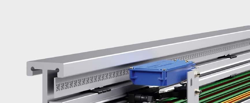
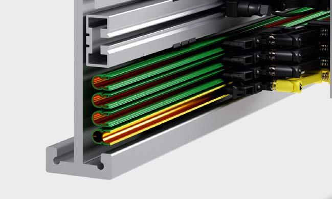
2 2 CONTENTS General Information...2 Technical Data...4 Joint Splice/Feed...5 Feed Terminal...5 Isolating Assembly...5 Spacer Clip...5 Expansion Section...6 Transfer Guides...6 Anchor Bracket (aluminum) for Transfer Guide...7 Standard Compact Hangers...8 Locating Clamp...8 Customer Specifi c Compact Hangers...9 Compact Current Collector Set KDS2/ Compact Current Collectors Set KUFR2/ Entry Funnel Compact Current Collector KUFU Current Collector Brushes Current Collector Springs Connecting Cables Terminal Boxes Current Collector Brush Wear Indicator Installation Tools...17 Application Questionnaire Fig.1 VDE test fi nger GENERAL INFORMATION The U10 Insulated Conductor System has been designed in accordance with VDE It complies with current conductor system safety requirements and protects against accidental human contact as stipulated by VDE 0470, Part 1 (DIN EN 60526), (Protection classifi cation IP 21). Fig. 1 illustrates that the VDE test fi nger cannot make contact with current carrying components. Compact collectors provide accidental contact protection only when the contact brushes are correctly and fully inside the conductors and covered by the insulating shroud. Conductor systems located within reach of personnel, and with collectors exiting the conductors during operation, must have barriers or shut-off switches installed to prevent accidental contact. This is required only for conductor systems with operating voltage above 25 VAC or 60V DC. U 10 Conductor System is approved for indoor installations only. Conductor systems may consist of any number of conductors. Space requirements are minimal. Contact opening at either downward or sideways orientation is possible. Standard length for conductor sections is 6m, shorter sections are available. The standard PE conductor is marked with a continuous yellow stripe at the insulating shroud. The PE-VP ground conductor has a specifi cally shaped profi le which reliably prevents the PE-VP collector from entering a phase conductor; thus, the support structure cannot be inadvertently electrifi ed. APPROVALS UL Certifi cation. Please consult us when ordering COMPACT HANGERS Compact hangers are used for conductor installation and will also provide and maintain the defi ned 14 mm phase distance. Hanger center distance is max. 0.6 m at straight sections, 0.3 m at curved sections. JOINT SPLICE/FEED Joint Splice/Feeds are used to mechanically and electrically connect U10 conductor sections. The included Joint Splice cap protects personnel from accidentally making contact when the system is under current. Each Joint Splice/Feed can compensate for section expansion/contraction up to 4 mm. FEED TERMINALS A feed connection is possible at every Joint Splice. Also, each Isolating Assembly and Transfer Guide can serve as a feed location when a Feed Clip is installed. When additional feed points within a conductor section are required, Feed Terminals (inline only) may be installed.
3 3 TRANSFER GUIDES Transfer guides serve as protection of the conductor end as well as a mechanical system separation. They also facilitate reliable passage of collector brushes at movable track sections such as track switches and lift stations. Installed with an aluminum Anchor Bracket (BFU), Transfer Guides lock the conductor ends in place at the support track thus creating a system fi xpoint. ISOLATING ASSEMBLIES (AIR GAP) Isolating assemblies interrupt the electrical current fl ow in a conductor. To utilize Current Collectors with the operational task to switch current on/off is only permitted when using low energy control current. For control function, feed sections, maintenance sections etc. we are supplying Isolating Assemblies with or without SE Feed Clip. CURVES U10 Insulated Conductors can be bend horizontally or vertically. A Curve Bending Tool is available to produce curves at an installation site. CURRENT COLLECTORS Current Collectors are manufactured using impact resistant synthetic material and stainless steel components. Copper graphite or carbon contact brushes are used. The length of the Current Collector cable cannot exceed 3m if the installed overload protection is not rated for the current capacity of the cable. See also DIN VDE 0100, Part 430 and DIN EN Connecting cables as supplied are suffi ciently dimensioned for the listed nominal current. For installation variation reduction factors, as with DIN VDE , must be observed. DIN EN and DIN-EN stipulate that the reliability of PE systems using conductor brushes must be ensured. Doubling the PE Collector is a practical and simple solution to achieve compliance. INDUSTRIAL DESIGNATIONS DIN German Institute for Standards EN European Stansdard ISO International Organization for Standardization IEC International Electrotechnical Commission VDE German Electrotechnical Association IP International Protection type and classification UL Underwriters Laboratories SAFETY NOTE A safety distance of min. (0.5 m) between Conductor / Current Collector arrangement and other moving or fi xed equipment must be kept to prevent accidental injury of personnel! INSULATING SHROUD VALUES (ELECTRICAL) Dielectric insulation DIN Specific resistance IEC Surface resistivity IEC Leakage path resistance IEC Standard shroud, green > 25 kv/mm > 1 x Ohm x cm 2,1 x Ohm CTI 400 1,1 High temp. shroud, gray > 25 kv/mm > 1 x Ohm x cm 2,1 x Ohm CTI 400 1,1 INSULATING SHROUD VALUES (MECHANICAL) Bending rigidity ISO 178 Tensile strength ISO 527 UV resistance max. relative humidity Ambient temperature range (1) Flame test Standard shroud, green N/mm N/mm 2 Xenon test > 1500 < 100 % - 30 C to + 55 C Flame resitant, self extinguishing, UL 94 V0 High temp. shroud, gray N/mm N/mm 2 Xenon test > 1500 < 100 % - 30 C to + 85 C Flame resitant, self extinguishing, UL 94 V0
4 4 TECHNICAL DATA CONDUCTOR SECTION 11,2 11,2 11,2 CONDUCTOR SPACING Standard = 14 mm 17,5 5,5 R H Radius horizontal curve 17,5 5,5 R H Radius horizontal curve PH-Standard PE-Standard PE-VP Standard 7,9 17,5 BENDING CONDUCTORS Without pre-bending R 5000 mm At site: Horizontal curves 5000 mm R 750 mm Inward/outward facing curves 5000 mm R 750 mm Curves R 750 mm pls. inquire. CONDUCTOR CODE U = Unipole insulated conductor 10 = Shroud size 25 = Conductor cross section (mm²) C = Copper conductor E = Stainless steel conductor CONDUCTOR LENGTH 6 m (19.6") standard section, shorter sections available SUPPORT SPACING Straight sections 0,6 m (2 ) Curves 0,3 m (1 ) APROVAL Indoor installations only PHASE (STANDARD) U10 Standard green shroud Weight kg/m Phase (1) U10/25C-...PH-B 0, U10/25E-...PH-B 0, PE (STANDARD) U10 Standard green shroud Weight kg/m PE (1) U10/25C-...PE-A 0, U10/25E-...PE-A 0, PE-VP (STANDARD) U10 Standard green shroud Weight kg/m PE-VP (1) U10/25C-...VP-A 0, U10/25E-...VPG-A (4) 0, PHASE (HIGH TEMP. SHROUD) PE (HIGH TEMP. SHROUD) PE-VP (HIGH TEMP. SHROUD) U10 high temp. gray shroud Weight kg/m Phase (1) U10/25C-...PH-D85 0, U10/25E-...PH-D85 0, U10 high temp. gray shroud Weight kg/m PE (1) U10/25C-...PH-C85 0, U10/25E-...PE-C85 0, U10 high temp. gray shroud Weight kg/m PE-VP (1) U10/25C-...VP-C85 0, U10/25C-...VPG-C85 (4) 0, CONDUCTOR ENGINEERING DATA leakage distance shroud mm max. nominal Voltage (3) max. continuos current A resistance Ohm/1000m U10/25 C ,744 0,748 U10/25 E ,328 31,328 impedance (2) Ohm/1000m SELECTION OF CONDUCTORS Conductor selection must consider required current capacity and existing environmental conditions. U10/25 C Conductor System with copper conductor for main current, control signal and data U10/25 E Conductor System with stainless steel conductor for control signal and data transmission at corrosive environments (1) designation to be completed, e.g. U10/25E-6000PH-B for 6 m phase, order number The four-digit number (printed bold) at the type designation indicates the length of the conductor section. (2) Based on 14 mm conductor spacing at 50 Hz (3) Not with UL certifi cation U UL = 600 V (4) Only for curves facing inward The last numeral of the order number indicates the length of the conductor section in meters. Accordingly complete the order number with 1, 2, 3, 4, 5 or 6.

 Max.")
, at least one additional Compact Hanger required for each Isolating Assembly.")
5 5 JOINT SPLICE/FEED Max. 2 x 40 A continuous current Compensates for up to 4 mm section expansion/contraction caused by temperature fl uctuations ,5 120 Connecting cables not included, please order from page 15 Weight kg VM-UEV10/C 0, VM-UEV10VP/C 0, FEED TERMINAL (INLINE ONLY) Max. 2 x 50 A continuous current Connecting cable not included, please order from page ,5 120 Weight kg ES-UES10 0, ES-UES10VP 0, ISOLATING ASSEMBLY (AIR GAP) Max. 40 A continuous current Two halves are joined during installation Feed Clip SE 10 with tab connector 6,3 x0,8mm (max. continuous current 40 A), at least one additional Compact Hanger required for each Isolating Assembly. LT/LTE 10 7, without current SE 10 Description Weight kg comprising ST-LT/LT10 0,017 2 x LT/U ST-LT/LTE10 0,021 2 x LT/U 10 1 x Feed clip SE 10 ST-LTE/LTE10 0,025 2 x LT/U 10 2 x Feed clip SE SPACER CLIP to provide support for Isolating Assembly by fi lling gap between Isolating Assembly and web of aluminum monorail track at 16,5 mm system height (1). Weight kg EU-DK10/16,5 0, (1) System height = distance contact surface to back of Compact Hanger (at web of monorail track)


 43,5 18,7 BFU 10 B Transfer guide US10 (straight) 25 7,5 4,2 45 max. 6 20 35 max.")
6 6 EXPANSION SECTION single conductor, to be completed at installation site Expansion capability of Expansion Section must equal the max. expansion capability of the EMS track. Two Fix Points are required with each Expansion Section. Please order as required by the EMS track layout. An additional Compact Hanger is required for each 15 mm expansion capability. Please add to your order as required. Prefi nished, complete Expansion Sections are also available as a 800mm long section. STANDARD PE-VP Weight kg Expansion Weight kg Expansion VM-UDV10/C-30 0,052 up to 30 mm VM-UDV10/C-45 0,075 up to 45 mm VM-UDV10/C-60 0,104 up to 45 mm VM-UDV10VP/C-30 0,052 up to 30 mm VM-UDV10VP/C-45 0,078 up to 45 mm VM-UDV10VP/C-60 0,104 up to 60 mm TRANSFER GUIDES max. vertical and horizontal offset ±3 mm respective 37 24,5 BFU 10 A Transfer guide US10 S (oblique) 43,5 18,7 BFU 10 B Transfer guide US10 (straight) 25 7,5 4,2 45 max max ,5 Schleiffl äche 12 without current 67 without Feed Clip: US without current 79 with Feed Clip: USE 10 S (tab connector 6.3 x 0.8 mm) TRANSFER GUIDE max. 40 A continuous current Weight kg/m Version Feed Clip MU-US10 0,008 straight w/o MU-US10S 0,008 oblique w/o MU-USE10 0,012 straight with MU-USE10S 0,012 oblique with TRANSFER GUIDE FOR PE-VP max. 40 A continuous current w/o Feed Clip: US 10 PE-VP w/o Feed Clip: US 10 SP with Feed Clip: USE 10 S-VP (tab connector 6.3 x 0.8 mm) Weight kg/m Version Feed Clip Phase + PE MU-US10-VP 0,007 straight w/o MU-US10S-VP 0,007 oblique w/o MU-US10SP-VP 0,008 oblique positive w/o MU-USE10-VP 0,011 straight with MU-USE10S-VP 0,011 oblique with MU-USE10SP-VP 0,012 oblique positive with
 = 16.5 mm A No.")
. 14,5 for system height (1) = 16.5 mm A No.")
 = 10,5 mm 8,5 10 A No.")
 = 10.5 mm 10 Socked head screws inserted at front of EMS track. Anchor Bracket kit consists of: 1 x Anchor Bracket, 2 x socket head screws M5, 2 x roll pins. M 5 x 14 B No.")
7 8,5 7 ANCHOR BRACKET (ALUMINUM) FOR TRANSFER GUIDES to be bolted to the track Two holes to be drilled through the EMS track to screw on the Anchor Bracket from the back. Kit comprises: 1 x Anchor Bracket, 2 x hex screws M5 with lock washer, 2 x roll pins 2 x ,8 B M 5 x BFU 10A for system height (1) = 16.5 mm A No. of conductors A mm B mm Weight kg MU-BFU10H4/16,5/14-59/ , MU-BFU10H6/16,5/14-90/ , MU-BFU10H8/16,5/14-118/ , MU-BFU10H10/16,5/14-143/ , M 5 x 14 BFU 10B B 25 to be used when EMS track has been cut obliquely (see drawing page 6). 14,5 for system height (1) = 16.5 mm A No. of conductors A mm B mm Weight kg MU-BFU10H4/16,5/14-59/ , MU-BFU10H6/16,5/14-90/ , MU-BFU10H8/16,5/14-118/ , MU-BFU10H10/16,5/14-143/ , B M 5 x 14 BFU 10 for system height (1) = 10,5 mm 8,5 10 A No. of conductors A mm B mm Weight kg MU-BFU10H4/10/14-62/ , MONTAGESICHERUNG MU-BFU10H6/10/14-90/ , MU-BFU10H8/10/14-118/ , BFU 10V A for system height (1) = 10.5 mm 10 Socked head screws inserted at front of EMS track. Anchor Bracket kit consists of: 1 x Anchor Bracket, 2 x socket head screws M5, 2 x roll pins. M 5 x 14 B No. of conductors A mm B mm Weight kg MU-BFU10V4/10/14-59/ , MU-BFU10V6/10/14-90/ , MU-BFU10V8/10/14-118/ , (1) System height = distance contact surface to back of Compact Hanger (at web of monorail)


 6 conductor + SMGM max.")


8 8 STANDARD COMPACT HOLDER up to 10 conductors These Compact Hangers may be combined to support any number of conductors. b M5 x 7 tief a L 18 32,5 +1,5 40 max. conductors L a b Weight kg AH-KA10L-2/16,5-N-PA ,5 0, AH-KA10L-4/16,5-10N-PA ,5 0, AH-KA10L-6/16,5-10N-PA ,5 0, AH-KA10L-8/16,5-10N-PA ,5 0, AH-KA10L-10/16,5-N-PA ,5 0, COMPACT HOLDER KA10 (USED WITH SCREWS) 6 conductor + SMGM max. conductors L Weight kg AH-KA10-4/10,5-UNI-PA-SMG , AH-KA10-6/10,5-UNI-PA-SMG , LOCATING CLAMPS 2 ea. USK Location Clamps are required for each fi x point LOCATING CLAMP STANDARD Illustration shows positioning of the two Locating Clamps at a Compact Hanger Weight kg USK10 0, LOCATING CLAMP PE-VP Illustration shows positioning of the two Locating Clamps at a Compact Hanger Weight kg USK10A-VP 0,

9 9 COMPACT HANGERS (CUSTOMER SPECIFIC) Engineered and manufactured to fi t customer specifi c EMS track


 143 332 - SA-KDS2/40/5/14HS0,5/4/6/6 5 56 90-0,549 6 cond. (No. 6 open) - 168 083 SA-KDS2/40/6/14VP0,5/4/6 6 56 90-0,637 6 cond. 143 219 - SA-KDS2/40/6/14HS0,5/4/6 6 56 90-0,637 6 cond.")

10 10 COMPACT COLLECTOR SETS KDS2/40 PE-VP for EMS installations with 1 x 0.5 m connecting cable type WFLA 2,5 max. current: 1 connecting cable 2.5 mm 2 25 A 2 connecting cables 2.5 mm 2 40 A Stroke: ± 15 mm Swivel: ± 15 mm Contact pressure: approx. 3.5 N per contact brush Connecting cable: 2.5 mm 2 type WFLA 2,5 high fl ex included PE standard at No. 4 position, variations are possible. PE makes contact fi rst when entering conductors. No. of cond. Dim. a mm Dim. b mm Dim. c mm tab connector 6.3 x 0.8 for WFLA 2.5 Weight kg GF 1 DF 3 Base plate b a c 15 max with PE-VP SA-KDS2/40/4/14VP0,5/4/ ,428 4 cond DF 1 max tab connector 6.3 x 0.8 connecting cable Typ WFLA 2.5 mm 2 with PE Standard SA-KDS2/40/4/14HS0,5/4/ ,428 4 cond SA-KDS2/40/5/14VP0,5/4/6/ ,549 6 cond. (No. 6 open) SA-KDS2/40/5/14HS0,5/4/6/ ,549 6 cond. (No. 6 open) SA-KDS2/40/6/14VP0,5/4/ ,637 6 cond SA-KDS2/40/6/14HS0,5/4/ ,637 6 cond SA-KDS2/40/7/14VP0,5/4/8/ ,744 8 cond. (No. 8 open) SA-KDS2/40/7/14HS0,5/4/8/ ,744 8 cond. (No. 8 open) SA-KDS2/40/8/14VP0,5/4/ ,832 8 cond SA-KDS2/40/8/14HS0,5/4/ ,832 8 cond SA-KDS2/40/9/14VP0,5/4/10/ , cond. (No. 10 open) SA-KDS2/40/9/14HS0,5/4/10/ , cond. (No. 10 open) SA-KDS2/40/10/14VP0,5/4/ , cond SA-KDS2/40/10/14HS0,5/4/ , cond Single conductor available with 0.5 m connecting cable Phase, black PE, yellow SA-KDS2/40/04PH-88/15-0,5 0,091 without SA-KDS2/40/30VP-79/15-0,5 0,105 without SA-KDS2/40/04PE-88/15-0,5 0,090 without CURRENT COLLECTOR SETS (TRAILING UNIT) Single conductor on base plate. PE standard at No. 4 position, variations possible! Dim. a mm Dim. b mm Dim. c mm Weight kg Base plate PE-VP PE SA-KDS2/40/1/14VP0,5/4/4/ ,164 4 cond SA-KDS2/40/1/14HS0,5/4/4/ ,164 4 cond D SA-KDS2/40/1/14VP0,5/4/6/1-3U ,197 6 cond SA-KDS2/40/1/14HS0,5/4/6/1-3U ,197 6 cond SA-KDS2/40/1/14VP0,5/4/8/1-3U ,216 8 cond SA-KDS2/40/1/14HS0,5/4/8/1-3U ,216 8 cond


 144 478 - SA-KUFR2/40/7/14HS0,5/8/8 7 0,779 8 cond. (No. 8 open) - 165 930 SA-KUFR2/40/8/14VPO,5/4/8 8 0,872 8 cond.")

 Single conductor on base plate. PE standard at No. 4 position, variations possible! Dim. a mm Dim. b mm Dim.")

11 11 KUFR2/40 for installations requiring bi-directional travel with 1 x 0.5 m connecting cable type WFLA 2,5 max. current: 1 connecting cable 2.5 mm 2 25 A 2 connecting cables 2.5 mm 2 40 A Stroke: ± 15 mm Swivel: ± 15 mm Contact pressure: approx. 3.5 N per contact brush Connecting cable: 2.5 mm 2 type WFLA 2,5 Lenght: 0.5 m, high fl ex included PE standard at No. 4 position, variations are possible. Dimensions of base plate see KDS2/40. PE makes contact fi rst when entering conductors. No. of Weight Base plate cond. kg 98 tab connector 6.3 x 0.8 für WFLA 2.5 max. 145 with PE-VP SA-KUFR2/40/4/14VP0,5/4/4 4 0,448 4 cond Flach stecker anschluss 6.3 x 0.8 connecting cable Typ WFLA 2.5 mm 2 with PE-Standard SA-KUFR2/40/4/14HS0,5/4/4 4 0,448 4 cond SA-KUFR2/40/5/14VPO,5/4/6/6 5 0,573 6 cond. (No. 6 open) SA-KUFR2/40/5/14HS0,5/6/6 5 0,573 6 cond. (No. 6 open) SA-KUFR2/40/6/14VPO,5/4/6 6 0,666 6 cond SA-KUFR2/40/6/14HS0,5/6 6 0,666 6 cond SA-KUFR2/40/7/14VPO,5/4/8/8 7 0,779 8 cond. (No. 8 open) SA-KUFR2/40/7/14HS0,5/8/8 7 0,779 8 cond. (No. 8 open) SA-KUFR2/40/8/14VPO,5/4/8 8 0,872 8 cond SA-KUFR2/40/8/14HS0,5/8 8 0,872 8 cond SA-KUFR2/40/9/14VPO,5/4/10/10 9 1, cond. (No. 10 open) SA-KUFR2/40/9/14HS0,5/10/10 9 1, cond. (No. 10 open) SA-KUFR2/40/10/14VPO,5/4/ , cond SA-KUFR2/40/10/14HS0,5/ , cond Single conductor available with 0.5 m connecting cable Phase, black PE, yellow SA-KUFR2/40/20PH-88/15-0,5 0, SA-KUFR2/40/20PE-88/15-0,5 0, SA-KUFR2/40/04VP-79/15-0,5 0, CURRENT COLLCETOR SETS (TRAILING UNIT) Single conductor on base plate. PE standard at No. 4 position, variations possible! Dim. a mm Dim. b mm Dim. c mm Weight kg Base plate PE-VP PE SA-KUFR2/40/1/14VP0,5/4/4/ ,164 4 cond SA-KUFR2/40/1/14HS0,5/4/4/ ,164 4 cond SA-KUFR2/40/1/14VP0,5/4/6/1-3U ,197 6 cond SA-KUFR2/40/1/14HS0,5/4/6/1-3U ,197 6 cond SA-KUFR2/40/1/14VP0,5/4/8/1-3U ,216 8 cond SA-KUFR2/40/1/14HS0,5/4/8/1-3U ,216 8 cond

12 12 ENTRY FUNNEL EFT10 to be used with Current Collector KUFU25 or KESR32 Please note: Entry Funnel without current. Entry speed: max. 100 m/min Entry tolerance: horizontal: ± 10 mm vertical: ± 10 mm Version with PE-VP please inquire; KESR required C 15 A B D max , ,5 62,5 No. of cond. A mm B mm C mm D mm Weight kg MU-EFT10-2-KUFU , MU-EFT10-3-KUFU , MU-EFT10-4-KUFU , MU-EFT10-5-KUFU , MU-EFT10-6-KUFU , MU-EFT10-7-KUFU , MU-EFT10-8-KUFU , MU-EFT10-9-KUFU , MU-EFT10-10-KUFU ,


13 88 13 COMPACT CURRENT COLLLECTOR SETS KUFU25 max. 138 for Entry Funnel EFT10 With 1 m connecting cable type FLA max. continuous current: 25 A RF 3 Stroke: +15 mm / -10 mm Swivel: ±15 mm Contact pressure: approx. 3,5 N per contact brush PE at No. 4 position, with 3 conductors at No. 3, with tab connector 6.3 x 0.8 für FLA 2.5 a b c 15 7 max DF 2 2 conductors at No. 2. Variations are possible. PE makes contact fi rst when entering conductors. No. of cond. Dim. a mm Dim. b mm Dim. c mm Weight kg Base plate mit PE ohne PE SA-KUFU25/2/14HS1,0/2/ , polig SA-KUFU25/2/14SS1,0/ , polig SA-KUFU25/3/14HS1,0/3/4/ , polig (Nr. 4 = frei) SA-KUFU25/3/14SS1,0/4/ , polig (Nr. 4 = frei) SA-KUFU25/4/14HS1,0/4/ , polig SA-KUFU25/4/14SS1,0/ , polig SA-KUFU25/5/14HS1,0/4/6/ , polig (Nr. 6 = frei) SA-KUFU25/5/14SS1,0/6/ , polig (Nr. 6 = frei) SA-KUFU25/6/14HS1,0/4/ , polig SA-KUFU25/6/14SS1,0/ , polig SA-KUFU25/7/14HS1,0/4/8/ , polig (Nr. 8 = frei) SA-KUFU25/7/14SS1,0/8/ , polig (Nr. 8 = frei) SA-KUFU25/8/14HS1,0/4/ , polig SA-KUFU25/8/14SS1,0/ , polig SA-KUFU25/9/14HS1,0/4/10/ , polig (Nr. 10 = frei) SA-KUFU25/9/14SS1,0/10/ , polig (Nr. 10 = frei) SA-KUFU25/10/14HS1,0/4/ , polig SA-KUFU25/10/14SS1,0/ , polig Single conductor available, without connecting cable Phase, black PE, yellow SA-KUFU25/28PH-78/15-0,0 0, SA-KUFU25/28PE-78/15-0,0 0,

14 14 COLLECTOR BRUSHES width of Contact Brushes = 3.8 mm GF GF 1 35 RH RH 23 RH RH SK-KMKU SK-KMKF2/ KMKF2/40VP GF GF RH DF3 Cam DF3 Cam SK-DSW2/ FN SK-DSW2/40VP FN Min. remaining Brush height (RH) = 3 mm for Current Collector Weight kg SK-KMKU KUFU25 0, SK-DSW2/ FN KDS2/40 0, SK-DSW2/40VP FN KDS2/40 PE-VP 0, SK-KMKF2/ KUFR2/40 0, SK-KMKF2/40VP KUFR2/40VP 0, SPRINGS S S D D L D L Compression Spring DF3 L Tension Spring RF3 Alignment Spring GF1 Cam for Current Collector S mm D mm L mm DF3 KDS2/40 0,55 9,55 24, RF3 KUFU25, KUFR2/40 0,40 4,40 31, GF1 KDS2/40, KUFR2/40-2,00 21, Cam KDS2/
 CONNECTING CABLE, DOUBLE INSULATION for Current Collector or Feed Terminal WFLA Length: 0.5m with tab plug 6.3 x 0.")


15 15 CONNECTING CABLE CONNECTING CABLE, HIGHLY FLEXIBLE for Current Collector, Feed Terminal, Transfer Guide and Isolating Assembly (for Current Collector KDS and KUFR use Connecting Cable WFLA 2.5) CONNECTING CABLE, DOUBLE INSULATION for Current Collector or Feed Terminal WFLA Length: 0.5m with tab plug 6.3 x 0.8 Longer connecting cable available FLA / FKA FH Length: 1m with tab plug 6,3 x 0,8 Longer connecting cable available Cross section mm 2 Ø mm Weight kg Phase PH PE PH PE black PE green/yellow AL-FLA2,5PH1-6,3 2,50 3,9-0, AL-FLA2,5PE1-6,3 2,50-3,6-0, AL-FLA4PH1-6,3 4,00 5,4-0, AL-FLA4PE1-6,3 4,00-5,2-0, AL-FLA6PH1-6,3 6,00 5,7-0, AL-FLA6PE1-6,3 6,00-5,7-0, AL-WFLA2,5PH0,5-6,3 2,50 3,9-0, AL-WFLA2,5PE0,5-6,3 2,50-3,6-0, CONNECTING CABLE, SINGLE INSULATION for Isolating Assembly only Cross section mm 2 Ø mm Weight kg Bestell-Nr. Phase PH PE PH PE black Bestell-Nr. PE green/yellow AL-IFKA1,5PH1-6,3 1,50 3,0-0, AL-IFKA1,5PE1-6,3 1,50-3,0-0, AL-IFKA2,5PH1-6,3 2,50 3,7-0, AL-IFKA2,5PE1-6,3 2,50-3,7-0, AL-IFKA4PH1-6,3 4,00 4,3-0, AL-IFKA4PE1-6,3 4,00-4,3-0, AL-IFKA6-PH1-6,3 6,00 4,9-0, AL-IFKA6-PE1-6,3 6,00-4,9-0, TAB PLUG ONLY (WITHOUT CABLE) for cable cross section mm 2 Weight kg FH2,5 2,5 0, FH , WFH2,5 2,5 0,


16 16 TERMINAL BOX TERMINAL BOX AKE for conductor current supply with max. 7 x 6 mm 2 terminal clamps and 2 x 6 mm 2 PE terminal clamps. Please inquire when terminal clamp variations are desired M 25 x 1,5 Weight kg ES-AKE1-PH7x2L6-PE2x2L6-M25 0, BRUSH WEAR INDICATOR Brush wear indicator can be supplied installed on 0.5 m conductor section. Please specify the corresponding conductor arrangement when ordering. The Brush Wear Indicator checks the remaining brush height each time a collector set passes. Max. travel speed 70m/min. When the remaining brush height reaches the preset value of 3 mm the Brush Wear Indicator will send an impulse. It is practic a l t o i n s t a l l t h e B r u s h We a r I n d i c a t o r a h e a d o f a t r a c k s w i t c h, t h e n t h e i m p u l s e c a n actuate the track switch to send the unit directly into a maintenance spur. An opening, min. width 70mm height 50mm, must be cut at the EMS track web. PE position is variable, similarly to the conductor arrangement; please inquire. Differing remaining brush height settings above 3 mm are also available. BRUSH WEAR INDICATOR WITH INDUCTIVE PROXIMITY SWITCH The last slot of a Brush Wear Indicator with an uneven number of conductors remains unoccupied. No. of conductors Weight kg PE-VP at No. 4 PE at No. 4 VT-KVT VP4B 4 2, VT-KVT HS4B 4 2, VT-KVT VP4B/6 5 2, VT-KVT HS4B/6 5 2, VT-KVT VP4B 6 2, VT-KVT HS4B 6 2, VT-KVT VP4B/8 7 2, VT-KVT HS4B/8 7 2, VT-KVT VP4B 8 2, VT-KVT HS4B 8 2, VT-KVT VP4B/10 9 3, VT-KVT HS4B/10 9 3, VT-KVT VP4B 10 3, VT-KVT HS4B 10 3,
 Filler rod for PH/PE (4 m) 0,371 165 234 MU-FU10-H (2) Filler rod for PH/PE (4 m) 0,354 144 416 MZ-FU10-S-VP Filler rod for")

17 17 INSTALLATION TOOLS CURVE TOOL for forming U10 vertical and horizontal curves. Filler Rods must be ordered separately. Description Weight kg MZ-BVU10-VP Curve tool 6, MZ-FU10-V (1) Filler rod for PH/PE (4 m) 0, MU-FU10-H (2) Filler rod for PH/PE (4 m) 0, MZ-FU10-S-VP Filler rod for PE-VP hollow body (4 m) 0, MZ-FU10-VP-E Filler rod for PE-VP contact surface (4 m) 0, TABLE SAW for cutting U10 insulator shroud and conductor profi les, with length stop Voltage required: 230 V, 50 Hz Description Weight kg MZ-KS10 Table Saw, compl. 6, MZ-SB spare saw blade 0, CONDUCTOR PUNCH TOOL for punching Joint Splice window into conductor profi le after cutting standard length section. For phase and PE and PE-VP conductors. Standard PH/PE PE-VP Description Weight kg MZ-LZ10PE-VP Conductor Punch Tool for PE-VP 0, MZ-LZ10PH/PE Conductor Punch Tool for Phase und standard PE 0, DEBURRING FILE RF HRF use for Weight kg ROUND FILE RF-150 LANG/HIEB 3/D=6MM deburr inside profile after cutting section 0, HALF ROUND FILE HRF-150 LANG/HIEB 3 deburr outside profile after cutting section 0, ADJUSTMENT JIG facilitates cutting precise length of insulation shroud without using measuring tape. Weight kg MZ-ST10 0, (1) For making vertical EMS curve sections. (2) For making horizontal and outward facing AEM curve sections.
18 18 JOINT SPLICE/FEED ASSEMBLING TOOL To push conductor into Joint Splice clip If necessary, to widen conductor slot opening To move Joint Splice cap in place Weight kg MZ-MG-SW10 0, LOCKING PIN DRIVER to insert BFU Anchor Bar Transfer Guide locking pins Weight kg MZ-ED10 0, CONDUCTOR REMOVAL TOOL to release and remove conductors from Compact Hangers Weight kg MZ-DMW10 0, DRILLING JIG FOR FIX POINT (PE-VP) Weight kg MZ-BS10A 0, SPIRAL DRILL to drill holes for Locating Clamps USK 10A-VP at fi x points Weight kg SPIRAL DRILL Ø 3,2 MM, TYPE N 0, INSTALLATION TOOL BOX includes 1x BVU10-VP Curve Tool, with Filler Rods 1x FU10, 1x FU10S-VP and 1 xfu10vp-e, 1x KS10 Table Saw, 1x SB spare blade, 1x LZ10PE-VP and 1x LZ10PH/PE Conductor Punch Tool, 1x RF round fi le and 1x HRF half round fi le, 1x ST10 Adjustment Jig, 1x MG-SW 10 Joint Splice/Feed assembly tool, 1x ED10 Locking Pin Driver, 1x DMW10 Conductor Removal Tool, 1x BS10A Drilling Jig, 1x spiral drill Ø 3,2 mm Installation tool box can be locked. Weight kg MZ-MWK-K 26,
19 19 APPLICATION QUESTIONNAIRE FOR U10 Customer Final customer Installation Date Project No. CUSTOMER CONTACT Name Fon Technical planning Purchasing SCOPE OF SUPPLY vconductor vpos vcom vdrive Installation VAHLE components Disassembly Installation Non-VAHLE components Disassembly Non-VAHLE components SCHEDULE Proposal submittal week/date Delivery week/date Installation start fi nish week/date weekdays weekends MECHANICAL DATA 1. INSTALLATION CONCEPT: New installation Alteration / Expansion Replacement 1:1 Original Conductor System Delivery No.: Original Conductor System Delivery No.: 2. ART DER ANLAGE: EMS Skillet system Floor Track Systems (2 tracks) Other 3. CARRIER TRACK / CARRIER TRACK SUPPLIER / TRACK DESIGNATION: 180x60 / / 240x80 / / Other / / 4. CONDUCTOR ORIENTATION: Facing sideways in direction of travel: right left Facing downward 5. INSTALLATION HEIGHT: Off facility fl oor or support fl oor mm freely traversible 6. TRACK EXPANSION GAPS: Expansion distance / gap dimension mm
20 20 7. BUILDING EXPANSION GAPS: Expansion distance / gap dimension mm 8. SPECIFIC BUILDING FEATURES: ELECTRICAL DATA 9. OPERATING VOLTAGE: Three-phase current Alternating current Direct current V Hz 10. TYPE OF CONDUCTOR: U10/25C copper conductor U10/25E stainless steel conductorl 11. NUMBER OF CONDUCTORS (POLES): Main current Control current Ground (PE) standard PE-VP Ground conductor with phase collector avoidance protection available only in copper 12. CONDUCTOR SEQUENCE: Compact hanger number of conductors Location top to bottom: Conductor Position Example 12. Cond. Hanger w/6 pos. used 1. open 2. open 3. L1 4. L2 5. L3 6. PE-VP 7. C1 8. C2 9. open 10. open 11. open 12. open 13. TRAVEL MODE: One direction only bi-directional / % 14. TRAVEL SPEEDS: Travel speed V max. straight: m/min Travel speed V max. curve: m/min Acceleration m/s² acceleration time s
21 CONNECTING CABLES FOR CONDUCTORS Joint Splice/Feed, Feed Terminal main current conductors cross section mm² Track switch Transfer Guides main current conductors cross section mm² Feeds and Transfer Guides control current cross section mm² ENVIRONMENTAL REQUIREMENTS 16. INSTALLATION LOCATION Indoors Cool storage Freezer (to 30 C) 17. AMBIENT TEMPERATURE INSTALLATION TEMPERATURE C min. C max. approx. C 18. RELATIVE HUMIDITY % OXYGEN REDUCED ATHMOSPHERE at ambient temperature C Oxygen content % 19. EXTRAORDINARY ENVIRONMENTAL CONDITIONS: vpos - POSITIONING SYSTEM 20. TYPE: APOS Optic Support system for Leuze Barcode (35 mm) APOS Magnetic vcom - DATA TRANSMISSION 21. TYPE: SMGM Powercom (utilizing conductor system) Semi-Wave (utilizing conductor system, only together with vdrive) CAN-Bus (utilizing conductor system, only together with vdrive) CONFIGURATION NOTES: Not suited for outdoor installation.

22 22 QUANTITY FRAMEWORK Position Quantity Piece/m Description 1. pieces carrier 2. m length total 3. m length straight 4. pieces H-curves to 15 R= mm 5. pieces H-curves to 30 R= mm 6. pieces H-curves to 45 R= mm 7. pieces H-curves to 60 R= mm 8. pieces H-curves to 75 R= mm 9. pieces H-curves to 90 R= mm 10. pieces H-curves to 180 R= mm 11. pieces TS-connection curves R= mm 12. pieces V-curves to 45 R= mm 13. pieces two-way track switches 14. pieces three-way track switches 15. pieces V-track switches 16. pieces turntables 17. pieces quattro track switches 18. pieces lift stations vertical No. of connections beams 19. pieces shift units horizontal No. of connections beams 20. pieces track expansions 21. pieces building expansions 22. pieces brush wear indicator 23. pieces PE verification 24. pieces connecting cables, capacity 25. pieces connecting cables, PE 26. pieces connecting cables, control 27. pieces terminal boxes 28. pieces conductor vacuum incl. suction head REMARKS
23 DRAWINGS 23

24 Paul Vahle GmbH & Co. KG Westicker Str Kamen Germany Fon.: Fax: W /00-E /18 Errors and technical changes reserved.
MACHT STROM MOBIL. Insulated Conductor Systems U10
 MACHT STROM MOBIL Insulated Conductor Systems U10 2a/en 2014 Table of Contents Basic description...2 Technical Data...4 Joint Feed...5 Feed Terminal...5 Isolating Assembly...5 Distance Bracket...5 Expansion
INSULATED CONDUCTOR SYSTEMS U10
 INSULATED CONDUCTOR SYSTEMS U10 INSULATED CONDUCTORS U 10 Index Page Basic description 3 Insulated conductors 4 Feed-in joint splice 5 Expansion section 5 Isolating assembly 5 Transfer guide 6 Compact
INSULATED CONDUCTORS U 15 - U 25 - U 35
 INSULATED CONDUCTORS U 15 - U 25 - U 35 INSULATED CONDUCTORS U 15 U 25 U 35 Index U 15 U 25 U 35 Page Page Page Basic description 4 4 4 Selection of conductors 5 23 34 Insulated conductors 5 23 34 Joint
Multi Support Profile VMT SYSTEMS IN MOTION
 Multi Support Profile VMT SYSTEMS IN MOTION 3c/en 2013 2 Multi Support Profile (VMT) Content The VAHLE solution for automation...3 System layout...4 Technical data...4 VMT - Multi Support Profile...5 Joint
Compact Conductor System VKS10 SYSTEMS IN MOTION
 Compact Conductor System VKS10 SYSTEMS IN MOTION 3a/en 2016 Content General...3 System diagram...5 Sections...6 Pole configuration...7 Curved sections...8 Fixpoint hanger...9 End cap...9 Sliding hanger...9
COMPACT CONDUCTOR SYSTEMS VKS 10
 COMPACT CONDUCTOR SYSTEMS VKS 10 POWERAIL ENCLOSED CONDUCTORS VKS 10 CONTENTS Page General 2, 3 Planning guide 4 Application photos 5 Technical data, standard sections 6, 7 Curved sections and jointing
POWERAIL ENCLOSED CONDUCTOR SYSTEM VKS 10
 POWERAIL ENCLOSED CONDUCTOR SYSTEM VKS 10 POWERAIL ENCLOSED CONDUCTORS VKS 10 CONTENTS Page General 2, 3 Planning guide 4 Technical data, standard sections 6, 7 Curved sections 8 Jointing material 8 Hangers
POWERAIL ENCLOSED CONDUCTOR SYSTEM VKS 10
 POWERAIL ENCLOSED CONDUCTOR SYSTEM VKS 10 POWERAIL ENCLOSED CONDUCTORS VKS 10 CONTENTS Page General 2, 3 Planning guide 4 Technical data, standard sections 6, 7 Curved sections 8 Jointing material 8 Hangers
Multipole Conductor Rail MultiLine Program 0831
 Multipole Conductor Rail MultiLine Program 0831 Contents Description / Technical Data Description....2 Technical Data....3 Conductor Rails Rails complete with pre-mounted Connector...4 Power Feeds....5
Energy Supply Systems
 Energy Supply Systems SINGLE POLE INSULATED CONDUCTOR RAIL 815 100 amps KAT0815-0001b-E Conductor rail system in a high bay storage Slip ring with conductor rail system in a stretch-foil packing machine
INSULATED CONDUCTOR SYSTEMS U 20 U 30 U 40
 INSULATED CONDUCTOR SYSTEMS U 20 U 30 U 40 INSULATED CONDUCTORS U 20 U 30 U 40 INDEX U 20 U 30 U 40 Page Page Page Basic description 4 4 4 Selection of conductors 5-10 5-10 5-10 Conductors 11 24 34, 35
POWERAIL ENCLOSED CONDUCTOR SYSTEMS VKS VKL
 POWERAIL ENCLOSED CONDUCTOR SYSTEMS VKS VKL 19 12 POWERAILS VKS & VKL INDEX VKS VKL Basic description 3, 4 3, 4 Layout planning 5 5 Engineering data, Powerail standard sections 6, 7 23 Powerail curves
Energy Supply Systems
 Energy Supply Systems MULTIPOLE CONDUCTOR RAIL 831 10-125 amps KAT0831-0001b-E 13 pole multipole conductor rail in 33 package distribution centres of the postal service (Post AG) 9 pole multipole conductor
4 pole insulated conductor rails ULA 35A, 50A, 80A, 100A
 Table of contents General information... 3 Elements of the conductor rail supply line... 3 Innovative connection method... 3 Technical properties... Construction of the line section... Line section...
Insulated Conductor Rail SinglePowerLine Program 0812
 Insulated Conductor Rail SinglePowerLine Program 0812 Table of Contents System Description 5 Technical Data 6 General Instructions 7 System Structure 8 Components and their use....8 Insulated Conductor
Bolted, snap-in and guarter turn type hangers are available. Standard support distance for U12 is 600mm, in curves 300mm.
 General Komay insulated conductors U12 are designed in accordance with today s international safety requirements. The shroud which envelopes the various conductors is an excellent insulator. Therefore
Insulated Conductor Rail SinglePowerLine Program 0813
 Insulated Conductor Rail SinglePowerLine Program 0813 Table of Contents System Description 5 Technical Data 6 General Instructions 7 System Structure 8 Components and their use... 8 Insulated Conductor
Insulated Conductor Rail SinglePowerLine Program 0812
 Insulated Conductor Rail SinglePowerLine Program 0812 2 Table of Contents System Description 5 Technical Data 6 General Instructions 7 System Structure 8 Components and their use... 8 Insulated Conductor
POWERAIL ENCLOSED CONDUCTOR SYSTEM KBH
 POWERAIL ENCLOSED CONDUCTOR SYSTEM KBH POWERAIL KBH Contents Page Contents Page System photo 2 Removing sections, Conductor dead sections 14 General 2, 3 Anti-condensation sections, Expansion sections
MACHT STROM MOBIL. Enclosed conductor system KBH SYSTEMS IN MOTION
 MACHT STROM MOBIL Enclosed conductor system KBH SYSTEMS IN MOTION 4b/en 2013 2 Enclosed conductor system KBH Content... Page Description of the Conductor system... 3 Technical description... 4 Technical
POWERAIL ENCLOSED CONDUCTOR SYSTEM KBH
 POWERAIL ENCLOSED CONDUCTOR SYSTEM KBH POWERAIL KBH Contents Page Contents Page System photo 2 Removing sections, Conductor dead sections 14 General 2, 3 Anti-condensation sections, Expansion sections
4 pole insulated conductor rails ULA 35A, 50A, 80A, 100A
 Table of contents General information... 3 Elements of the conductor rail supply line... 3 Innovative connection method... 3 Technical properties... Construction of the line section... Line section...
4 pole insulated conductor rails UNILIFT-ULA 35A, 50A, 80A, 100A
 2 Table of contents General information... 4 Elements of the conductor rail supply line... 4 Innovative connection method... 5 Technical properties... 6 Construction of the line section... 6 Line section...
1 Product Description Check of the supplied Parts Notes Intended Use Current Collector... 3
 Order number 0813xx-... Contents 1 Product Description... 2 2 Check of the supplied Parts... 2 3 Notes... 2 4 Intended Use... 2 5 Current Collector... 3 6 Installation Sequence... 3 7 Pickup Guide... 7
ProEMS Insulated Conductor Rail for Electrified Monorail Systems Program 0815
 ProEMS Insulated Conductor Rail for Electrified Monorail Systems Program 0815 Supplementary Documents Installation instructions: MV0815-0007-EN Installation Instructions for Conductor Rail System 0815
1 Product Description System Layout Safety Instructions Intended Use Installation... 3
 Order Number 0812xx- Contents 1 Product Description... 2 2 System Layout... 2 3 Safety Instructions... 3 4 Intended Use... 3 5 Installation... 3 5.1 Hanger Clamp... 3 5.2 Cutting of Conductor Rail... 4
Thermal-Magnetic Circuit Breaker 201/-WA
 Thermal-Magnetic Circuit Breaker 0/-WA Description Single pole thermal-magnetic circuit breaker with tease-free, trip-free, snap action mechanism and two button operation (M-type TM CBE to EN 60934). Featuring
GENERAL INDEX TR60. 6 YELLOW LINE Continuous Conductors. Max 5 Poles. 8 BLUE LINE Pre-Mounted Conductors TR85H5P. YELLOW LINE Continuous Conductors
 2 Automation - Lift - Handling System GENERAL INDEX 2 DESCRIPTION 3 BUSBAR LINE VERSIONS LINE TYPE / AMPERAGE COVERAGE 5 TR60 40 A 50 A 60 A 70 A 100 A 140 A 160 A 200 A 320 A 6 YELLOW LINE Continuous
ProEMS Insulated Conductor Rail for Electrified Monorail Systems Program 0815
 ProEMS Insulated Conductor Rail for Electrified Monorail Systems Program 0815 Supplementary Documents Installation instructions: MV0815-0007-EN Installation Instructions for Conductor Rail System 0815
MR - MEDIUM RATING A
 88 MR - MEDIUM RATING 160-1000A SECTION CONTENTS 90 General features 96 Advantages 100 Illustrated contents MR MEDIUM RATING 102 Trunking components 110 Feed units and end covers 113 Tap-off boxes 118
FABA. Standard Components. Conductor Bar System. publication #FABASC-04 1/1/04 Part Number: Copyright 2003 Electromotive Systems
 FABA Conductor Bar System Standard Components publication #FABASC-04 1/1/04 Part Number: 000-2201 Copyright 2003 Electromotive Systems Table of Contents Section IS 100 A - Introduction General Information
Conductor Rail System for Shuttles MultiLine Program 0835
 MultiLine Program 0835 Table of Contents General Information 5 System Advantages 5 Main Features at a Glance 6 Technical Data 7 Conductor Rail 8 End Segment (End Power Feed) 8 Rail Connector 9 Standard
Thermal Overcurrent Circuit Breaker 3120-F...
 Thermal Overcurrent Circuit Breaker 20-F... Description An extremely versatile range of rocker switch/thermal circuit breakers (Stype TO CBE to EN 6094 with trip free mechanism) offering the choice of
Electronic Circuit Breaker ESS20-0..
 Electronic Circuit Breaker ES-0.. Description Electronic circuit breaker type ES-0.. is designed to ensure selective disconnection of individual loads in systems which are powered by a DC 4 V switch-mode
panasonic.net/id/pidsx/global Solve issues related to machine safety and other safety measures with a safety door switch with key!
 655 Door with Key SERIES Related Information General terms and conditions... F-7 General precautions... P.50 PHOTO PHOTO Conforming to Machine & EMC Directives Recognition Certified MEASURE ITY panasonic.net/id/pidsx/global
Multipole Conductor Rail MultiLine Program 0831
 Multipole Conductor Rail MultiLine Program 0831 ProShell - the modular carrier profile as a system supplement for program 0812 and 0831 ProShell catalog KAT0800-0003-E available for download at www.conductix.com
Thermal Overcurrent Circuit Breaker 3120-F...
 Thermal Overcurrent Circuit Breaker 20-F... Description An extremely versatile range of rocker switch/thermal circuit breakers (S-type TO CBE to EN 6094 with trip free mechanism) offering the choice of
4 Pole / 5 Pole Enclosed Conductor System
 4 / 5 Pole Conductor System 4 Pole / 5 Pole Enclosed Conductor System Enclosed Conductor system with IP23 Finger proof cellular profile. Available in intensities from 20 Amp 200 Amp Data sheet ref : 10
Thermal Overcurrent Circuit Breaker 3120-F...
 Thermal Overcurrent Circuit Breaker 20-F... Description An extremely versatile range of rocker switch/thermal circuit breakers (Stype TO CBE to EN 6094 with trip free mechanism) offering the choice of
MACHT STROM MOBIL. Battery Charging Systems
 MACHT STROM MOBIL Battery Charging Systems 10a/en 15 2 Battery Charging Systems Content...Seite General...3 Models...4 General installation instructions...7 The operation of Automatic Guided Vehicles (AGVs)
Magnetic and Hydraulic-Magnetic Circuit Breaker 8340-G V
 Description Single and two pole magnetic circuit breakers with trip-free mechanism and push/pull on/off manual actuation. A choice of fast magnetic only or hydraulically delayed switching characteristics
Magnetic Overcurrent Circuit Breaker
 Magnetic Overcurrent Circuit Breaker 808-... Description ngle pole miniaturised magnetic circuit breakers with unique highspeed operating mechanism and push/pull on/off manual actuation. Fitted with electrically
1 Product Description System Layout Safety Instructions Intended Use Installation... 3
 Part Number 0812xx- Contents 1 Product Description... 2 2 System Layout... 2 3 Safety Instructions... 3 4 Intended Use... 3 5 Installation... 3 5.1 Hanger Clamp... 3 5.2 Cutting of Conductor Rail... 4
POWERAIL CONDUCTOR SYSTEMS MKLD MKLF MKLS
 POWERAIL CONDUCTOR SYSTEMS 19 12 POWERAIL INDEX Page Powerail versions 3 Basic description 3 Technical data 3 Powerail types, cat. nos. and weights 4 Engineering data and configurations 5 Standard sections,
Technical data. DKK compact conductor lines engb IS eps
 Technical data DKK compact conductor lines 4146644.eps 10910 engb 0 540 44 714 IS 9 Contents 1 Technical information Straight sections 4 Curved sections 5 4 Powerfeeds 6 5 Ramp sections, expansion joints
BETA Switching Switches and Light Indicators
 Siemens AG 2008 BETA Switching /2 Product overview /3 5TE8 control switches / 5TE4 pushbuttons /2 5TE5 light indicators /5 5TE8 ON/OFF switches /22 5TE9 busbars /24 5TE switch disconnectors Siemens ET
Thermal Overcurrent Circuit Breaker 3120-F...
 Thermal Overcurrent Circuit Breaker 20-F... Description An extremely versatile range of rocker switch/thermal circuit breakers (Stype TO CBE to EN 6094 with trip free mechanism) offering the choice of
High Performance Thermal-Magnetic Circuit Breakers 410/520/
 High Performance Thermal-Magnetic Circuit Breakers 0/0/30-... Description Single, double and three pole high performance thermal-magnetic circuit breakers with tease-free, trip-free, snap action mechanism
Thermal Circuit Breaker / Switch Series 3131
 Thermal Circuit Breaker / Switch Series 33 Description Combination of single pole circuit breaker and ON/OFF switch with soft-touch rocker actuation. Contoured rockers are available with a choice of colours
Thermal-Magnetic Circuit Breaker 2210-S291-P9M A
 Thermal-Magnetic Circuit Breaker 0-S9-P9M-40033-...A Description Single pole thermal-magnetic circuit breaker with trip-free mechanism and toggle actuation. Two-chamber construction with cascade contact
12 Page. tehalit.ba7a wide-slot wiring duct tehalit.ba7b narrow-slot wiring duct tehalit.b7a solid duct 12.12
 The system of equipment of the boards is a wide range proposing solutions for each type of application: - the series tehalit.ba7a in PVC cover the whole current needs, - series tehalit.ha7 in PC-ABS halogen
Pro-Ductor Insulated flat conductor bar for 4, 7 or 10 conductors
 Darwinstraat 10 NL 6718 XR Ede The Netherlands Flexible with energy! Phone +31 (0)342 403900 Fax +31 (0)342 403912 email info@akapp.com URL www.akapp.com Pro-Ductor Insulated flat conductor bar for 4,
Thermal Overcurrent Circuit Breaker 3120-F...
 Description An extremely versatile range of rocker switch/thermal circuit breakers (S-type TO CBE to EN 6094 with trip free mechanism) offering the choice of single pole, double pole with single pole protection,
Enclosed Conductor System MKH SYSTEMS IN MOTION
 MACHT STROM MOBIL Enclosed Conductor System MKH SYSTEMS IN MOTION 4c/en 4c/de 2016 2015 Enclosed conductor system MKH Content Description of the conductor system... 3 Technical Data... 5 Technicall data
Thermal Overcurrent Circuit Breaker 3120-F...
 Thermal Overcurrent Circuit Breaker 0-F... Description An extremely versatile range of rocker switch/thermal circuit breakers (S-type TO CBE to EN 6094 with trip free mechanism) offering the choice of
Door Interlock Switches
 HSE Series HSE Series Miniature Solenoid Locking Switches Overview X Series E-Stops HSE features: World s smallest 4 contact solenoid interlock switch. (3 x x 46 mm) Four contacts Gold-plated contacts
GJL 100 A Molded Case Circuit Breaker GJL 75 A Motor Circuit Protector
 GJL 100 A Molded Case Circuit Breaker GJL 75 A Motor Circuit Protector Catalog 0500CT9702R409 2009 Class 525/580 CONTENTS Description............................................. Page General Characteristics...................................
Series T is Ideal for:
 Series T SAF-T-BAR Series T is Ideal for: Light Rail Systems Automated Storage and Retrieval Systems Conveyors Indoor, Dry Locations Small cranes, monorails, hoists Moving cameras and instruments Other
4-Ductor Insulated conductor bar
 Darwinstraat 10 4-Ductor AKAPP 4-Ductor current supply system compact, reliable and safe! AKAPP 4-Ductor is a compact, reliable and safe current supply system for cranes, hoists, monorail systems, conveyor
DC Cabling Ready for 1,500 V DC
 DC Cabling Ready for 1,500 V DC Perfectly connected MADE IN GERMANY Reduce your LCOE with 1,500V DC architecture What causes PV costs? Since 2010 the PV market has changed a lot. PV module costs have been
PS5R-S. Switching Power Supplies
 TREICHL-ATM Electronic Auf der Bült 1-12 D 41189 Mönchengladbach Tel. 2166 8545 Fax 2166 8547 email: atm@treichl.de internet: www.atm-treichl.de PS5R-S Switching Power Supplies Class Create More Space
Underfloor to desk 231
 Technical information Underfloor to desk 231 Series 507 Powertrack Series 507 Powertrack is an underfloor busbar system rated at 63Amp maximum. It is available in Standard or CE (Clean Earth) versions.
Thermal Overcurrent Circuit Breaker 3130
 Thermal Overcurrent Circuit Breaker 330 Description Single, two and three pole rocker switch/thermal trip free circuit breakers (S-type TO CBE to EN 60934) of compact design for snap-in panel mounting.
Technical data. Standards: IEC/EN , EN ISO , IEC 61508, IEC
 AZM 00,,,,, M0x1, 0 1, AZM 00➀-T-➁➂ 0 1 Solenoid interlock (Solenoid interlock monitoring) Thermoplastic enclosure Sensor technology permits an offset of ± mm between actuator and interlock Intelligent
1 Product Description Check of the supplied Parts Notes Intended Use Current Collector... 3
 Part number 0813xx-... Contents 1 Product Description... 2 2 Check of the supplied Parts... 2 3 Notes... 2 4 Intended Use... 2 5 Current Collector... 3 6 Installation Sequence... 3 7 Pickup Guide... 6
ELECTRIFICATION OF RTG CRANES
 ELECTRIFICATION OF RTG CRANES MAKING PORTS MORE SUSTAINABLE WITH ertg SOLUTIONS Up to 95 % savings in diesel fuel costs Up to 95 % savings in diesel fuel costs the ECOLOGICAL solution the ECOLOGICAL solution
Thermal Overcurrent Circuit Breaker 3120-F...
 Thermal Overcurrent Circuit Breaker -F... Description An extremely versatile range of rocker switch/thermal circuit breakers (S-type TO CBE to EN 694 with trip free mechanism) offering the choice of single
Thermal Circuit Breaker 3120-F...
 Description The 320 circuit breaker/switch combination is an ON/OFF switch with integral overcurrent protection (S-type TO CBE to EN/IEC 60934). The trip element is a bimetal. Type 320 is ideally suited
Lenze. Drives with worm gearboxes 52.
 6 887 Lenze Drives with worm gearboxes 5. Lenze Drive Systems GmbH, Postfach 0 5, D-76 Hameln, Site: Groß Berkel, Hans-Lenze-Straße, D-855 Aerzen, Phone ++9 (0) 55 8-0, Telefax ++9 (0) 55 8- E-Mail: Lenze@Lenze.de
DC Single-Acting High Performance Solenoids
 DC Single-Acting High Performance Solenoids 1 Product group G TC A Function Increasing magnetic force vs. stroke characteristic Push and pull type Construction Robust closed cylindrical design Fastening
Door Interlock Switches
 HS5B Series HS5B Series Miniature Interlock Switch HS5B features: mm x mm x 9mm Compact Housing Available with Contact Confi gurations (NO + NC or NC) Flexible Installation: By turning the head of the
SG-B1 SERIES / SG-A1 SERIES
 643 Door with Solenoid Interlock / Door Ultra-slim SG-B1 SERIES / SG-A1 SERIES Related Information General terms and conditions... F-7 General precautions... P.1501 PHOTO PHOTO Conforming to Machine &
Pro-Ductor Insulated flat conductor bar for 4, 7 or 10 conductors
 Wabtec Netherlands B.V. Darwinstraat 10 NL 6718 XR Ede The Netherlands Flexible with energy! Phone +31 (0)342 403900 Fax +31 (0)342 403912 Email info@akapp.com URL www.akapp.com Pro-Ductor Insulated flat
Manual Electronic Identification Systems BIS Read/Write Heads C3-slk_716464_E_1110.p65 Deutsch bitte wenden!
 C3-slk_716464_E_1110.p65 1 Manual Electronic Identification Systems BIS s Deutsch bitte wenden! 2 No. 716 464 D/E Edition 1110 Subject to modification. Replaces edition 1104. Balluff GmbH Schurwaldstrasse
Page. Circuit-Breakers M4 2 for motor protection. Auxiliary contacts 3 Signalling switch Auxiliary releases
 Circuit Breakers M4 Page Circuit-Breakers M4 2 for motor protection Auxiliary contacts 3 Signalling switch Auxiliary releases Insulated 3-pole busbar system 4 Terminal block DIN-rail adapters 5 Busbar
UNCHAINED ENERGY ELECTRIFICATION OF TRAVELLING MACHINES
 UNCHAINED ENERGY ELECTRIFICATION OF TRAVELLING MACHINES As a leading specialist in electrical power supply, FELS is broadening its MOBILIS range with a highly innovative line of singleconductor rails boasting
Insulated Conductor Rail SingleFlexLine Program 0811
 Insulated Conductor Rail SingleFlexLine Program 0811 Contents System Description 5 Technical Data 6 System Components and Standards 7 Components and their use...7 Project Planning 9 Technical notes and
Proportional solenoid valve for pneumatic application V PR M
 Proportional solenoid valve for pneumatic application 3 Product group V PR M Function 2/2 NC Proportional direct-acting Armature pressure tight up to 16 bar static pressure Short correction times High
Thermal Overcurrent Circuit Breaker 3120-F...
 Thermal Overcurrent Circuit Breaker 0-F... Description An extremely versatile range of rocker switch/thermal circuit breakers (S-type TO CBE to EN 6094 with trip free mechanism) offering the choice of
General notes. Operating conditions
 1 General notes Wöhner busbar systems and components are the result of expert development based on many years of experience. They have been exhaustively tested and hold many approvals. The correct selection
Control switch/load disconnect switch Series 8008
 > s Control switch with 2, 3 or 4 pole Load switch 3 pole + 1 auxiliary contact > Rated operational voltage up to 690 V AC > Positive opening contacts > Contacts suitable for EM-STOP > Isolating characteristics
Electromotive Systems ELECTROBAR 8-Bar Conductor Bar System
 Electromotive Systems ELECTROBAR 8-Bar Conductor Bar System ELECTROMOTIVE SYSTEMS ELECTROBAR 8-BAR CONDUCTOR BAR SYSTEMS The practical, proven and economical way to deliver electricity to overhead cranes,
Conductor Bar Safe-Lec 2 Hevi-Bar II
 Conductor Bar Safe-Lec 2 Hevi-Bar II Contents Safe-Lec 2 and Hevi-Bar II Overview 3 Conductor Bar Summary Chart 4 Quick Quote Software 5 Quotations Data Sheet 6-7 Safe-Lec 2 8-33 Safe-Lec 2 System Components
UNCHAINED ENERGY ELECTRIFICATION OF TRAVELLING MACHINES
 UNCHAINED ENERGY ELECTRIFICATION OF TRAVELLING MACHINES MOBILIS MOVIT : ELECTRIFICATION LINE WITH SINGLE POLE CONDUCTOR RAILS 315A - 450A - 630A HIGHER PERFORMANCE Designed in aluminium with a stainless
Conductor Bar Safe-Lec 2 Hevi-Bar II
 Conductor Bar Safe-Lec 2 Hevi-Bar II Contents Safe-Lec 2 and Hevi-Bar II Overview 3 Conductor Bar Summary Chart 4 Quick Quote Software 5 Quotations Data Sheet 6-7 Safe-Lec 2 8-33 Safe-Lec 2 System Components
Solenoid interlock AZM 200 The non-contact interlock.
 Solenoid interlock AZM 200 The non-contact interlock. Solenoid interlock AZM 200 The non-contact Solenoid interlocks demand accurate alignment of actuator and device. This requirement is met on new machinery.
Capanivo Series CN 4000
 Capanivo Series CN 4000 Instruction manual 010516 1 UWT GmbH Westendstraße 5 Tel.: +49 (0)831 57123-0 Internet:www.uwt.de D-87488 Betzigau Fax: +49 (0)831 76879 E-Mail: info@uwt.de Scope of this instruction
ALINOX INSULATED CONDUCTOR RAIL FOR ELECTRICAL FEEDING OF CRANES
 ALINOX INSULATED CONDUCTOR RAIL FOR ELECTRICAL FEEDING OF CRANES 2 ALINOX INSULATED CONDUCTOR RAIL Features, advantages and benefit The insulated conductor rail system ALINOX is the most suitable solution
Proportional solenoid valve for pneumatic application V PR M
 Proportional solenoid valve for pneumatic application 3 Product group V PR M Function / NC Proportional direct-acting Armature space pressure tight up to 16 bar static pressure High linearity Quick response
Electronic Circuit Breaker ESS20
 Electronic Circuit Breaker ESS20 Description Electronic circuit breaker type ESS20 is designed to ensure selective disconnection of individual loads in systems which are powered by a DC 24 V switch-mode
Thermal Overcurrent Circuit Breaker 3130
 Thermal Overcurrent Circuit Breaker 330 Description Single, two and three pole rocker switch/thermal trip free circuit breakers (S-type TO CBE to EN 609) of compact design for snap-in panel mounting. Available
Modular. Precise. Robust. AGE-S-XYZ Compensation Unit
 AGE-S Modular. Precise. Robust. AGE-S-XYZ Compensation Unit Compensation unit compensating in XY- and Z-direction Field of Application Palletizing, joining, and assembly of workpieces Advantages Your benefit
3SE3 1 SIGUARD Position Switches
 3SE3 SIGUARD Position Switches Metal-enclosed, with Moulded Cable Description Technical data Description In harsh industrial environments and in installations with limited space, the small 3SE3 6 and 3SE3
Thermal-Magnetic Circuit Breaker M1-..
 Thermal-Magnetic Circuit Breaker 30-...-M-.. Description Single or two pole rocker switch/thermal-magnetic circuit breaker with trip-free mechanism (S-type TM CBE to EN 34). The addition of a magnetic
VAHLE POWERCOM 485. Digital Data Transmission System
 VAHLE POWERCOM 485 Digital Data Transmission System 19 12 VAHLE POWERCOM 485 GENERAL INFORMATION VAHLE POWERCOM 485 Digital Data Transmission using VAHLE Conductor Systems VAHLE POWERCOM 485 is the latest
HS6B Series Subminiature Interlock Switch
 HS6B Series Subminiature Interlock Switch HS6B features: Only 78 x 30 x 15mm Allows highest level of safety by having 3 contacts: dual load contacts + monitoring contact (ISO13849-1, EN954-1) Two actuator
INTRODUCTION. The plug-in connection on the cables and lightning arrestors, allows for easy installation and replacement.
 INTRODUCTION The Power Systems 44 kv MiniSub TM is the most compact system at this voltage available. Utilizing a deadfront termination and lightning arrestor setup, it eliminates the line top or side
ENERGY. Solar Cables
 ENERGY Solar Cables Contents TECSUN(PV) PV1-F Cables for Photovoltaics 3 Technical Data 4 Design Features 6 Selection and Ordering Data 6 TECSUN DUO (PV) Cables for Photovoltaics 7 Technical Data 8 Design
USER'S MANUAL and INSTALLATION GUIDE
 AM Inlet Series 8" and 2" baffle AM0896GS AM296GS USER'S MANUAL and INSTALLATION GUIDE TABLE OF CONTENTS Section Page...Requirements for Installation...2 2...Unpacking the AirManager... 3-5...Exploded
Thermal-Magnetic Circuit Breaker M1-...
 Thermal-Magnetic Circuit Breaker 320-...-M-... Description Two pole rocker switch/thermal-magnetic circuit breaker with trip-free mechanism (S-type TM CBE to EN 6034). The addition of a magnetic tripping