Insulated Conductor Rail SingleFlexLine Program 0811
|
|
|
- Terence Stone
- 6 years ago
- Views:
Transcription

1 Insulated Conductor Rail SingleFlexLine Program 0811
2
3 Contents System Description 5 Technical Data 6 System Components and Standards 7 Components and their use...7 Project Planning 9 Technical notes and engineering information...9 Dimensioning the Conductor Rail System...11 Conductor Rail arrangement and curves...11 Using Rail Connectors as Expansion Joints...12 Parts of the Conductor Rail System 14 Insulated Conductor Rails...14 Rail Connectors Curves...15 Power Feeds Anchor Clamps...17 Air Gaps End Caps Cable Lugs...18 Hanger Clamps Installation Examples of Hanger Clamps...20 Pickup Guide, short type Pickup Guide, long type Current Collectors 23 Current Collectors, general description...23 Types of Current Collectors...24 Towing Arm Current Collector Support Bracket...26 Connection Cables Replacement Parts 28 Current Collector Head, 48 mm...28 Current Collector Head, 68 mm...28 Stabilization Springs for Current Collector Head...28 Tools and Assembly Accessories 29 Bending Device Notching Pliers...29 Cutting Pliers Rail Calibration Tool Release Pliers System Layout 31 Conductor Rail Program Summary 33 3
4 4
5 SingleFlexLine Program 0811 The SingleFlexLine Conductor Rail Program 0811 is used as a standard product in countless applications in the industrial sector. It has the advantages of a high rigidity due to the profile s geometry, and the unique, tool-free connection method with bayonet couplings. By enlarging the notch in the Conductor Rail, every Rail Connector can be used as an Expansion Joint, thus eliminating the need for costly and time-consuming installation of additional Expansion Joints.To match the routing of your rail system, you can use the Bending Device (page 29) to adjust the rails radii and you can easily adjust the number of poles. This makes the system ideal for electrified monorail systems (EMS), sorter systems, and similar installations. The 0811 system can also to be turned into slip ring assemblies for 360 degree rotation. The 0811 Conductor Rail System is available in a variety of conductor and insulating materials and can be adjusted to meet most general requirements. The plastic insulation of the conductor rails is colored safety yellow in accordance with general marking regulations. PE (protective earth) conductor rail components are yellow with green stripe. Additionally, the 0811 Conductor Rail System is available with the Safety System PE plus (see catalog KAT Conductor Rails for Electrified Monorail Systems ). The specially designed PE plus protective earth conductor profiles and copper graphite shoes cannot be inadvertently inserted into a phase rail. This safety system is compatible with existing components and can be retrofitted in sections without needing to change the mounting positions of the Conductor Rails or Current Collectors. All connecting components of the PE plus system, e.g. End Caps and Rail Connectors, are colored green. PE plus correctly inserted into PE rail A distinctive feature of the SingleFlexLine 0811 is the easy installation and adaptation of its individual components. Most of the installation can be done without using tools, by simply clipping in or turning in parts. For other operations, simple standard tools can be used. Special installation tools, if needed, can be bought or rented for the duration of the installation. PE plus cannot inadvertently be inserted into phase rails The SingleFlexLine program is a modular system that can be adjusted to the requirements of energy and data transmissions for mobile consumers. This product is intended for indoor use or weatherproof outdoor use corresponding to protection class IP 23 for Conductor Rails in the field of Electrified Monorail Systems and similar applications. For installation multi-pole Hanger Clamps are available, as well as combination holders for the accommodation of conductor rails, code and barcode tapes, and data transmision lines for contact-free data communication along the routings. Other applications can be configured with any number of poles, routing characteristics, and mounting positions. Please note that the applicability of our components, due to the multitude of options and variable general and environmental conditions, has to be reviewed case-bycase. An express warranty cannot be given for attributes and functions in applications which differ from intended use and technical data. The components of a Conductor Rail system are classified as a partly complete machinery and are to this extent subject to the machinery directive for use in the european union (MRL 2006/42/EG). IEC Test Finger Insulating material Plastic insulation Y-axis ø ø 75 ø R2 ± 0.05 Conductor Rail X-axis 5 ± Testing of contact protection with IEC/UL/NEMA jointed test finger (12 mm foreign body) 5
6 Technical Data System Installation orientation System length Pole spacing Rated suspension spacing System length Travel speed Single pole Conductor Rail System for indoor and weather-protected outdoor use in Electrified Monorail Systems and similar applications User-defined avoid installation with acces opening upturned (foreign body ingress + reduced protection type) 4000 mm 20 mm Nom mm (see table hanger clamps) Unlimited (depending on power feed concept) Max. 600 m/min (restrictions for certain components and rail radii) Rated voltage Nom. 690 V / 500 V UL (min. voltage 24V / min. current 3A) Permitted ambient temperature Max. temperature difference K 50 C -10 to +55 C (higher temperatures possible on request / rail insulation), -30 C on request Max. insulation temperature Standard (PVC): 85 C, heat-resistant variant (PPE + PS-I): 115 C Protection type Storage temperature Min. installation temperature Local approvals IP 23 (rail system, Current Collector only when inserted) -30 to +40 C; store away from sunlight, avoid condensation -10 C (recommended installation temperature: above 0 C) UL / CSA / GOST-R Specific values Conductor material Hot-dip galvanized steel Electrolytic copper Data metal Type Current Load at 100% duty cycle and 35 C (rated value) [A] DC resistance at + 35 C [Ω / 1000 m] at + 20 C [Ω / 1000 m] Impedance at + 35 C [Ω / 1000 m] Impedance at + 20 C [Ω / 1000 m] Moment of inertia Ix [cm 4 ] Moment of inertia Iy [cm 4 ] Modulus of resistance Wx [cm³] Modulus of resistance Wy [cm³] Chemical resistance Insulating material Installation material Conductor material PVC: good general chemical resistance PPE + PS-I: average general chemical resistance, critical when in direct contact with oil PC, PA, PBT: PC, PA, PBT: good general chemical resistance, partly limited Data metal: good chemical resistance Galvanized steel: limited resistance Copper: limited resistance Information about chemical resistance are general notes and depend on temperature, exposure time, concentration and interactions, and need to be verified in individual cases. Please contact us before usage in critical environmental conditions such as galvanizing plants, pickling plants, compost works, and locations with high concentrations of chemicals (e.g. solvents, aromates, benzols, etc.) for the purpose of alternative installation positions, materials and possibly necessary additional components. Insulation cover Material Stabilized hard PVC; safety warning color (RAL 1018) or PPE + PS-I (halogen-free) (RAL 1021) Dielectric strength 22.4 kv (PVC), 45 kv (PPE + PS-I) as defined by DIN Leakage current resistance Flammability Note: Some restrictions may apply in combinations of certain requirements 400 < CTI as defined by IEC 112 / VDE 0303 (PPE + PS-I: 300 < CTI) Meets requirements for insulation materials in UL 94 V-1; Flame retardant and self-extinguishing (IEC ), halogen-free PPE-SB 6
7 System Components and Standards Conductor Rail System Components The modular system SingleFlexLine 0811 is divided into basic components and additional components not necessarily used in all applications. Basic Components 1 2 Conductor Rail Rail Connectors 2 3 Hanger Clamps End Caps End Cap with Power Feed Current Collectors Examples for Additional Components: Pickup Guide, Air Gap 5 Note Owing to technical advancements of our products, this catalog cannot list all available variants and additional components. If needed, please contact our sales department. Relevant Standards DIN EN , VDE : DIN EN , VDE : DIN EN 60529, VDE : DIN EN , VDE : DIN EN 60093, VDE : DIN EN 60167, VDE : DIN EN 60112, VDE : Insulation coordination for electrical equipment in low-voltage installations - Part 1: Principles, requirements and testing (IEC :2007); German edition EN :2007 Safety of machines - electrical equipment of machines - Part 1: General requirements (IEC :2005, modified); German edition EN :2006 Protection classes using housings (IP code) (IEC 60529: A1:1999): German edition EN 60529:1991 A1:2000 Electrical dielectric strength of insulating materials - testing procedures - part 2: Additional requirements for testing with direct current (IEC :2001); German edition EN :2001 Testing procedures for electrical insulation: Specific dielectric strength and specific surface resistance of solid, electrically insulating materials (IEC 60093:1980); German edition HD 429 S1:1983 Testing procedures for electrical insulation: Insulation resistance of solid, insulating materials (IEC 60167:1964); German edition HD 568 S1:1990 Process for determining the test figures and comparison figures for creepage path formation in solid, insulating materials (IEC 60112:2003); German edition EN 60112:2003 7
8 8

: Specific components and accessories are available for this scope of application (please see catalogue KAT0800-0002 Conductor Rails for Electrified Monorail")
9 Project Planning Technical Notes and Engineering Information 1. Application area and intended use The Conductor Rail System 0811 is designed as a modular, single-pole, and insulated system. Intended applications are facilities with mostly curved tracks and circular or oval applications with or without switches. Typical applications are electrified monorail systems, conveyors, sorters, and other conveyor systems in circular and oval arrays, as well as other indoor and weatherproof outdoor applications. Use in Electrified Monorail Systems (EMS): Specific components and accessories are available for this scope of application (please see catalogue KAT Conductor Rails for Electrified Monorail Systems ). For use in applications and/or requirements other than described, please contact us. 2. Rail material and voltage drop Conductor rails can be provided in copper or stainless steel, and for simple, short routings, in galvanized steel. Unlike typical linear track routings, electrified monorail systems, circular, and oval tracks have multiple power feeds and mostly small consumers, therefore voltage drop is not a critical factor. End Caps and Rail Connectors can be used as power feeding points. 3. Rail Connectors and Expansion Joints The 0811 Program uses a unique and proven system of bayonet couplings. By enlarging the notch in the Conductor Rail, every Rail Connector can be used as an Expansion Joint, thus eliminating the need for additional Expansion Joints. 4. Power Feed Rails are connected to the power supply network via Power Feed Connectors on the bayonet couplings. Additionally, End Caps and Rail Connectors can be used as Power Feeds by adding Cable Lugs. 5. Air Gaps and Insulating Elements These are used to separate sections or as ejection points for foreign bodies and abrasions. Air Gaps, unlike Insulating Elements, allow for safe electrical isolation even in case of material pollution and high abrasion. Insulating Elements for older facilities with block operation are available on request. 6. Anchor Clamps Anchor Clamps are used to fasten the rails at specified distances and fixed points. Fixed points are reference points where the rails are fastened to the sub-structure by Anchor Clamps and Hanger Clamps. From the fixed point the rail can expand and slide into the adjacent Hanger Clamp. The fixed point keeps the rail in place and keeps the system from slipping. 7. End Caps and Transfer Points End Caps are used to close rail end points and for protection against accidental contact with the rails. Transfer Points allow for the passage of graphite shoes between two disjoined rail sections. When used as Transfer Points, adjacent caps have to be aligned within a narrow tolerance range and factors like thermal expansion or varying load-carrying capacities causing mismatching rails must be taken into account. Crossing points, such as switches, lifters, etc. should be adjusted with hangers with medium to maximum load. If the rails cannot be adjusted due to the use of too few hangers, the system is not to be used until the crossing points have been properly aligned. Misalignment may result in damage to the Caps and Current Collectors. If setting a switch or lifter is possible, inspection intervals and setting values of the switch should be noted in the maintenance records to prevent rail system failures due to altered conditions at the crossing points. 9

10 Project Planning Technical Notes and Engineering Information 8. Hanger Clamps Sliding Hanger Clamps are used to fasten and position the rails. They ensure safe mounting of the rails while allowing the conductor rail to slip within the hanger in case thermal expansion occurs. Hanger Clamps are made from high-strength engineered plastic and are resistant to aging. Damage from aromates from the environment may occur if concentration and exposure time are exceeded. Hanger Clamps, as well as other plastic parts of the system, must not be painted or cleaned with solvents. Installation on painted surfaces is permissible only after drying and complete evaporation of the solvent. Please contact us if the system is to be used in facilities with aromate residue, such as flavor enhancers, benzenes, pickling agents, solvents and related substances. In this case, alternative plastics should be specified. 9. Pickup Guides Pickup Guides are used at transfer points with greater distances or as entry points for additional vehicles. When using Pickup Guides within track routings, tolerances during the various operating states have to be considered. When using Pickup Guides, Current Collectors with spacers must be used to ensure correct distances (pole spacing) between decoupled Current Collector Shoes. The Pickup Guides are insulating components as well as plastic running surfaces and are subject to wear. 10. Current Collectors When correctly installed Current Collectors provide proper contact with the Conductor Rails and are available with copper-graphite and pure carbon contact shoes. To ensure positive contact, installation distances and alignment with the rails running tread must be maintained by the customer. Positional changes due to curves or mounting tolerances must be allowed for when the system is active. The stated tolerances for the Current Collector refer to new, not yet worn-out contact surfaces. Simultaneous exploiting of the maximum x and y tolerances is not permissible. y x Special attention should be paid to the mounting position of the Current Collectors in rail circuits with curves. Ideally, Current Collectors should be mounted level with the rail contact point of the carriage. Deviating the Collector mounting positions as well as curves themselves change the distance to the rail and therefore modify the shoe pressure applied. This may result in increased wear of contact surfaces, possible damage to the system. Cables connected to the Current Collector must not exert pulling force on the Collector. Cables must be highly flexible so as to not deflect, move, change the shoe pressure on the rail, or limit the movement of the Current Collector. If the Current Collectors are to be installed within maintenance hatches, as is common with electrified monorail systems, sufficient free space for the cables must be provided. Flap hinges and latches have to be installed free of play and preferably adjustable, to avoid mismatching and vibrations. Foreign bodies like fastening screws must not compromise the movement of the cables and Current Collectors. Foreign bodies must not protrude into the mounting space of the Current Collectors. Copper-Graphite and Carbon Collector Heads Copper-Graphite Collector Heads Copper Graphite shoe material has a high mechanical strength and can be used to transmit higher currents. They are applied in systems containing Pickup Guides and multiple transfer points. Pure Carbon Pure Carbon Collector Heads Carbon Shoes are made from specially processed graphite material and combine good sliding and contact properties. Due to the high lubricant content of these shoes, they exhibit great running smoothness and high durability with less abrasion. They are well suited for data transmission due to low transition resistance (recommended minimum current load: 1 A). Their use for higher current loads is restricted. Pure Carbon Heads are brittle when compared to Copper-Graphite Heads. Therefore, to avoid breaking the Pure Carbon Shoes, it is recommended that new systems be run with Copper-Graphite Heads first, then switching to Pure Carbon Heads after the system has been broken in or when Collector Head replacement is due. Copper-Graphite Durability Since durability depends primarily on ambient conditions such as humidity, system behavior, velocity, operating mode, installation position, etc., statements about durability can be made only in context. Guidance values are available on request. 10
11 Project Planning Conductor Rail System Dimensioning The rail type is selected according to the total expected load current per route section and the voltage drop during start-up. Notes on voltage drop and special operating conditions The total current of all consumers running simultaneously must not exceed the stated load capacity of the rail at 100% duty cycle. Voltage drop on the conductor rail should not be higher than 3-5% U N. If facilities operate under extreme environmetal conditions, please contact us. Calculating the voltage drop Three-phase current Alternating current Direct current u = Voltage drop [V] Ig = Total current [A] u = 3 x L x Ig x Z [V] u = 2 x L x Ig x Z [V] u = 2 x L x Ig x R [V] R = resistance of the conductor rail [Ω/m] Z = impedance of the conductor rail [Ω/m] L = conductor rail length [m] Notes on rated current and dependance on ambient temperature The conductor rails specified rated current refers to a duty cycle of 100% according to european standards and to an ambient temperature of 35 C. The conductor rail will not exceed the maximum tolerable rail temperature under these conditions. At lower temperatures and shorter duty cycles the rail can handle higher current loads. A current load increase up to the maximum tolerable rail temperature is permissible. At temperatures higher than the reference value for the rated current at 35 C, self-heating needs to be reduced. In practice, this can be done by reducing the current load or shortening the duty cycle. Permissible ambient temperature dependent on duty cycle (specified for copper rail 100 A) Duty cycle 100% 80% 60% 40% 20% Permissible ambient temperature with standard insulation Permissible ambient temperature with heat-resistant insulation 55 C 57.5 C 60 C 62.5 C 65 C 85 C 92.5 C 100 C C 110 C Rail Layout and Curves Constructing curves is preferably done on-site by means of a bending device (see page 29). A straight section of at least 65 mm on each end of the curve is necessary for connecting. Rails can be bent down to the following radii: Smallest possible radius At the factory On-site Vertical 400 mm 500 mm Horizontal 1200 mm 2000 mm For further information on curves, please see page 15 Horizontal rail arrangements Vertical rail arrangements Inner curve Outer curve 11

12 Project Planning Using Rail Connectors as Expansion Joints If the conductor rail is installed inside or alongside a support structure, such as a crane runway or building s structure, changes in temperature will cause changes in the lengths of the support profile as well as the conductor rail. Due to the different materials used, the degree of expansion will vary. These variations, as well as expansion through self-heating or exposure to external heat sources must be compensated for to prevent compressing or warping of the conductor rail. Expansion Joints are generally used for this purpose. With the 0811 system, the and Rail Connectors act as expansion units, by cutting the notch according to Diagram 1 below Notching position Diagram 1 Adjusting the Air Gap t max t min 100 Example Temperature range: from +10 C (t min ) to +60 C (t max ) (Ambient temperature during installation (t inst ): +25 C) Definitions t min = lowest temperature that occurs in the application t max = highest possible working temperature in the application 1. Draw a connecting line from t min to t max 2. Draw the ambient temperature during installation (t inst ) as a horizontal line 3. Draw a vertical line down from the point of intersection of these two lines and read off the air gap to be used during installation Ambient temperature during installation [ C] t max t inst t min Air Gap [mm] Example expansion in buildings Multiple Rail Connectors are installed at intervals to compensate for expansions occuring in buildings (e.g. 30 mm). 12
13 Project Planning Diagram 2 Number of Connector/Expansion Units when using Steel and Data Metal Rails > 100 m Temperature difference [ C] Conductor Rail system length [m] Temperature difference = ru + rsw ru = Variability of ambient temperature rsw = Temperature increase by electric current = 5 C up to 50% duty cycle = 30 C up to 100% duty cycle Diagram 3 Number of Connector/Expansion Units when using Copper Rails > 100 m Temperature difference [ C] Conductor Rail system length [m] Diagram 4 2 DV 4 DV 6 DV 8 DV 10 DV 100 m 50 m FP a DV 50 m DV = Connector/Expansion Unit FP = Anchor Clamp L = Total Length a = Length inbetween two Expansion Units a = (L - 100) 2 Number of DV Two Expansion Units have to be installed in center between two Anchor Clamps! 13
 Protective Earth (PE) insulation is marked with a green stripe on both sides.")
 Standard (PVC) -10 C... 55 C 85 C 081116-4x11* 081116-4x12* 1.")

![200 Note: Please contact us if your temperature ranges differ from the above * Standard range Length [m] Weight [kg] Rail Connectors One-piece cover for power feeds up to 6 mm 2 Two-piece cover for](/docs-images/77/74972694/images/14-3.jpg "power feeds up to 10 mm 2 3 2 Type of rail connection Use onepiece cover Use twopiece cover Straight rails 10 A - 100 A x x Slip rings/curved tracks (r < 2 m) Power feeds up to 6 mm² x x x 1 Rail")
14 Conductor Rail System Components Insulated Conductor Rails 4000 mm 40 mm 3920 mm 40 mm Rail Types 8 mm 15 mm Scale 1:1 100A Solid Copper Rail 32A Galvanized Steel Rail 10A Data Metal Rail For control signals and bus information PE Type Type Type Insulation color: RAL 1018 (other colors by request) Protective Earth (PE) insulation is marked with a green stripe on both sides. Type / Conductor material Rated current 100% duty cycle Ambient temperature min. / max. Insulation temperature max. Phase PH Part No. Protective earth PE Galvanized Steel 32 A x x Copper 100 A Standard (PVC) Standard (PVC) -10 C C 85 C x11* x12* Data Metal 10 A x11* x12* Galvanized Steel 32 A x x Copper 100 A Heat-resistant (PPO/PPE) Heat-resistant (PPO/PPE) -10 C C 115 C x x Data Metal 10 A x x Note: Please contact us if your temperature ranges differ from the above * Standard range Length [m] Weight [kg] Rail Connectors One-piece cover for power feeds up to 6 mm 2 Two-piece cover for power feeds up to 10 mm Type of rail connection Use onepiece cover Use twopiece cover Straight rails 10 A A x x Slip rings/curved tracks (r < 2 m) Power feeds up to 6 mm² x x x 1 Rail Connector Notch position Power feeds up to 10 mm² x Rail Fast installation with bayonet couplings 14 Rail Connector with insulating cover Part No. For steel and data metal rails For copper rails Weight [kg] One-piece cover (see table above) Two-piece cover (see table above) * * * Standard range
15 Conductor Rail System Components Curves By using the Bending Device (see page 29), the rails can be adjusted to the needed routing or formed in a circular fashion on-site. Smaller curves or circular segments can be ordered from the factory as standard parts. Hanger Clamp Alignment for Curves 100 Inner Innenbogen curve 4000 Vertical rail arrangements 100 A = Hanger Clamp spacing (see table on page 19) Outer Außenbogen curve Rail Anordnung Connector der arrangement Schienenverbinder when bei Verwendung using standard von Normbogen parts Inner curve Outer curve Horizontal rail arrangements 400 A A Standard 0811 Curves Inner curve Rail opening, vertical arrangement Center line of the track section Outer curve Required length of straight section L 0 = Rail section L 1 = Insulating section L 0 = L L 1 = L L 2 = R 2 π α 180 R 1 = Radius of the track section R 2 = Radius of the contact surface R 3 = Inside radius of the conductor rail X = 20 + a a = Distance between R 1 and the seat area of the Hanger Clamp: - Installed on track section = 15 mm - Installed on support arm or C-rail = 17 mm Part Nos. for Curves Galvanized Steel Rail Min. Radius Part No HOR. 32A PH St-Is > HB x HOR. 32A PE St-Is > HB x HOR. 32A PH Wf-Is > HB x HOR. 32A PE Wf-Is > HB x 22 Copper Rail Min. Radius Part No HOR. 100A PH St-Is > HB x HOR. 100A PE St-Is > HB x HOR. 100A PH Wf-Is > HB x HOR. 100A PE Wf-Is > HB x 22 Data Metal Rail Min. Radius Part No HOR. 10A PH St-Is > HB x HOR. 10A PE St-Is > HB x HOR. 10A PH Wf-Is > HB x HOR. 10A PE Wf-Is > HB x 22 Galvanized Steel Rail Min. Radius Part No VER. 32A PH St-Is > VB x VER. 32A PE St-Is > VB x VER. 32A PH Wf-Is > VB x VER. 32A PE Wf-Is > VB x 22 Copper Rail Min. Radius Part No VER. 100A PH St-Is > VB x VER. 100A PE St-Is > VB x VER. 100A PH Wf-Is > VB x VER. 100A PE Wf-Is > VB x 22 Data Metal Rail Min. Radius Part No VER. 10A PH St-Is > VB x VER. 10A PE St-Is > VB x VER. 10A PH Wf-Is > VB x VER. 10A PE Wf-Is > VB x 22 St-Is = Standard Insulation up to 35 C Wf-Is = Heat-resistant Insulation up to 85 C 15

![3 mm 100% duty cycle For steel and data metal rails For copper rails Weight [kg] One-piece cover (see table page 14) 081151-21 081151-61 35 A Two-piece cover (see table page 14)](/docs-images/77/74972694/images/16-1.jpg "081156-21* 081156-61* 0.050 * Standard range Power feed with crimp cable lug 45 A and PE/protective earth connector 130 130 6 mm mm 2 max.")
 081151-22 6 mm 2 max.")
 081156-22* 081156-62* * Standard range Power feed with crimp cable lug 100 A and PE/protective earth connector 10 mm 2 max.")
16 Conductor Rail System Components Power Feed Connectors Power feed with cable lug 35 A (not for PE/protective earth connector!) mm 2 max. with cable lug Power feed with insulating cover PH Rated current Part No. with cable lug 6.3 mm 100% duty cycle For steel and data metal rails For copper rails Weight [kg] One-piece cover (see table page 14) A Two-piece cover (see table page 14) * * * Standard range Power feed with crimp cable lug 45 A and PE/protective earth connector mm mm 2 max. 2 max. with with cable lug crimp cable lug Power feed with insulating cover PH + PE Rated current Part No. with crimp cable lug 100% duty cycle For steel and data metal rails For copper rails Weight [kg] 130 One-piece cover (see table page 14) mm 2 max. with A crimp cable lug Two-piece cover (see table page 14) * * * Standard range Power feed with crimp cable lug 100 A and PE/protective earth connector 10 mm 2 max mm 2 max.with crimp cable lug Power feed with insulating cover PH + PE Rated current Part No. with crimp cable lug 100% duty cycle For steel and data metal rails For copper rails Weight [kg] One-piece cover (see table page 14) A Two-piece cover (see table page 14) * * * Standard range Note: For protective earth connector, use crimp cable lug only! 16

![Weight [kg] Anchor Clamp with ledge 081131* 0.](/docs-images/77/74972694/images/17-1.jpg "014 * Standard range Requirement: 2 Anchor Clamps per pole")

17 Conductor Rail System Components Anchor Clamps Anchor Clamp Type Part No. Weight [kg] Anchor Clamp with ledge * * Standard range Requirement: 2 Anchor Clamps per pole Air Gap Type Part No. Weight [kg] Air Gap * * Standard range Note: Air Gaps can be used as power feeds by inserting a cable lug (see page 18) 17


18 Conductor Rail System Components End Caps for Rail End Points and Transfer Points End Caps can be used as power feeds by inserting a cable lug. Note: If the end cap is used as a a protective earth connector, use crimp style cable lug only! End Cap M5 a b Insulation ~40 24 Rail End Cap Type 1-pole without power feed Application For galvanized steel and data metal rails Part No. For copper rails Dimension a [mm] Dimension b [mm] Weight [kg] x1x0* pole without power feed x3x0* pole without power feed Phase and protective earth x4x0* pole without power feed x5x pole without power feed x6x * Standard range Power Feed Cable Lugs For End Caps used as power feeds these cable lugs are clipped on the rail. Note: For End Cap Power Feeds used as protective earth, use connectors with crimp type cable lug only. Power Feed Cable Lug For End Feed in End Caps (max. 6 mm 2, 35 A), To be used for phase and control cables _1 Cable Lug Type Part No. Weight [kg] Power Feed Cable Lug for steel and data metal rails * Power Feed Cable Lug for copper rails * * Standard range for End Feed in End Caps (max. 6 mm 2, 45 A), to be used for phase, control, and protective earth cables. Type Part No. Weight [kg] _2 Crimp Type Cable Lug Power Feed Cable Lug for steel and data metal rails * Power Feed Cable Lug for copper rails * * Standard range Note: The Cable Lug must be clipped on the rail!


19 Conductor Rail System Components Hanger Clamps Hanger Clamps are compact, multi-poled clamps allowing for fast clip-on installation, securely fastening the conductor rails. The installation permits smooth longitudinal sliding of the rails during thermal expansion of the system. Hanger Clamps are fastened to the substructure (Conductix- Wampfler C-Rails (Program 0230) or Support Arms) with threaded screws or square nuts. Rail material Max. support distance A [m] Suspended Rail Crane Runway Curves Steel Copper Data Metal A/2 M Rail length 4000 A Support distance Rail Connector Power feed M6 M b b b b Hanger Clamp Part No. Type Clear width b With hex-nut With square-nut Weight [kg] 3-pole 60 mm x3x20* x3x20* / pole 80 mm x4x20* x4x20* / pole 100 mm x5x20* x5x20* / pole 120 mm x6x20* x6x20* / * Standard range 19

 or")


20 Conductor Rail System Components Installation example Hanger Clamps Surface-mount with angle bracket ➀ Installation example Hanger Clamps Mounted on C-Rail (Program 0230) or Support Arm ➀ ➀ Insert for force distribution. Hanger Clamps can be damaged if inserts are not installed. 20

21 Conductor Rail System Components Pickup Guide short type To be used with short type Current Collectors and long type Current Collectors for transfer operations. To compensate for misalignment of horizontal deflections ± 15 mm and vertical deflections of ± 8 mm. Max. permissible transfer speed: 60 m/min. Higher speeds available by request. max. 800 M b Slide surface c 65 a Reference to Current Collector mounting see System Layout on page 31 Type a [mm] b [mm] c [mm] Current Collector, short ~ b1 b2 b3 20 Current Collector, long ~ 200 The indicated nominal distance a between the center line of the Current Collector and the center line of the conductor rail must be changed by dimension b at the suspension of the pickup guide so that the clearance dimension c is guaranteed at this point. A sufficient number of Current Collectors must be installed in systems utilizing pickup guides. The Current Collectors must be installed with the correct distances to ensure the right number of collectors for the current required. The user has to ensure that while the collectors are between Pickup Guides they are de-energized or protected against accidental contact. Type Part No. Number of poles b1 [mm] b2 [mm] b3 [mm] Weight [kg] Pickup Guide 2-pole x2x Pickup Guide 3-pole x3x Pickup Guide 4-pole x4x Higher pole numbers are available by request 21


22 Conductor Rail System Components Pickup Guide long type To be used with long type Current Collectors for transfer operations. To compensate for misalignment of horizontal deflections ± 30 mm and vertical deflections of ± 25 mm. Max. permissible transfer speed: 80 m/min. Higher speeds avialable by request. 30 M max. 800 ~ b1 98 b2 b Slide surface Reference to Current Collector mounting see System Layout on page 31 ~ 320 A sufficient number of Current Collectors must be installed in systems utilizing pickup guides. The Current Collectors must be installed with the correct distances to ensure the right number of collectors for the current required. The user has to ensure that while the collectors are between Pickup Guides they are de-energized or protected against accidental contact. 22 Type Part No. Number of poles b1 [mm] b2 [mm] b3 [mm] Weight [kg] Pickup Guide 2-pole x2x Pickup Guide 3-pole x3x Pickup Guide 4-pole x4x Higher pole numbers are available by request
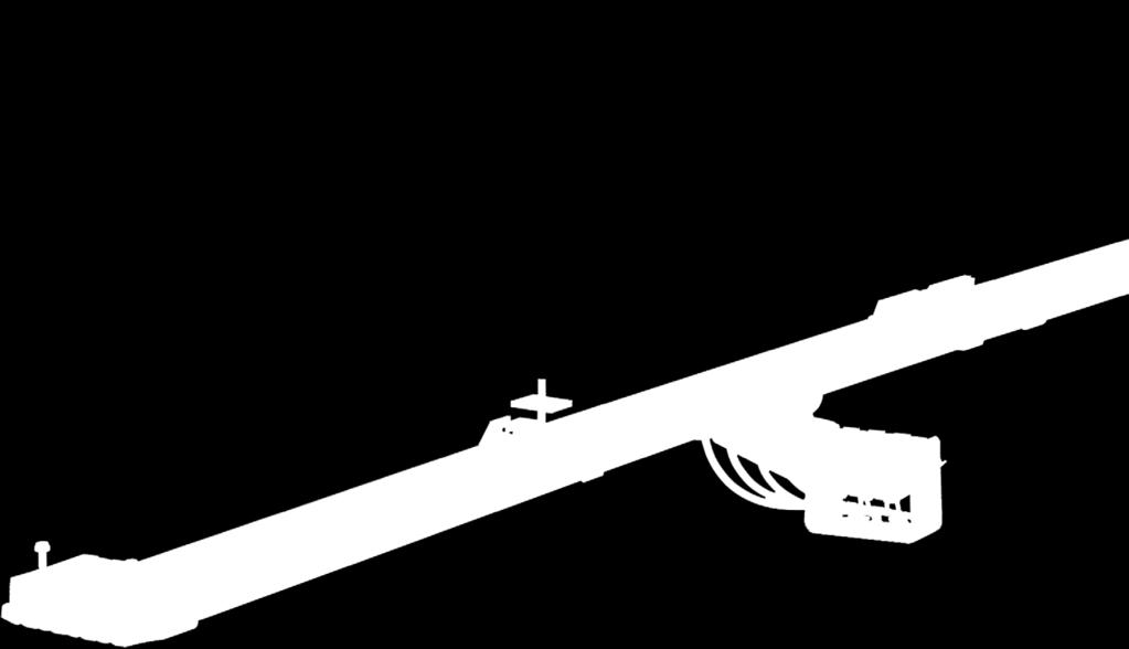
23 Current Collectors Current Collectors in general Depending on application and function, different types of Current Collectors are used: Cranes and conveyor systems, circular and oval rail systems Automotive sector Electrified monorail systems Other monorail systems Temporary structures and amusement park rides Current Collector short arm type Current Collector long arm type Current Collectors with safety system PE plus Current Collectors with safety system PE plus as required in the automotive sector Special versions are available by request with additional safety features and different set-up for higher dynamic requirements Version 1 short 40 mm-head: Preferred for systems with transfer points and separations with little variation in track course Version 1 short 40 mm-head: for systems with and without transfer points and separations with ordinary variations in track course Please see catalogue KAT Conductor Rails for Electrified Monorail Systems for further information Please see catalogue KAT Conductor Rails for Electrified Monorail Systems for further information Version 2 long 63 mm-head: Preferred for systems with transfer points and separations with little variation in track course Version 2 long 63 mm-head: Current Collectors with spacers must be used for systems with transfer points Current Collectors with spacers must be used for systems with transfer points PH-Version = to be used as phase and control cable (marked in black) PE = to be used as protective earth (marked in green) Carbon material Copper-Graphite Heads are used for higher current loads and systems with Pickup Guides. Pure Carbon Heads are preferred for lower current loads and data signals with higher running quality and low transition resistance between collector and conductor rail not suitable for systems with Pickup Guides/transfer points and discontinued tracks (risk of breakage in case of collision). Mounting position/tolerance notes Current Collectors can compensate for deviations of the nominal line in X- and Y-direction within a tolerance range (see page 10). When choosing the mounting position in systems with inner and outer curves, the envelope curve and resulting deviations from the nominal line have to be taken into account. Vertical tolerances (contact of the Collector Head with the rail) refer to new, not yet worn-out Collector Heads (gross tolerance). Simultaneously exploiting the maximum x-y tolerances is not permissible. When installing the Current Collectors in structures provided by the customer, fastening elements need to be installed free of play and vibrations, and placed in the required position (aligned with nominal distance to the conductor rail). If the Current Collectors are to be installed within maintenance hatches (as is common with electrified monorail systems), there must be sufficient free space to accommodate the cables. Flap hinges and latches have to be installed free of play and preferably adjustable to avoid mismatching and vibrations. Foreign bodies like fastening screws must not compromise the movement of the cables and Current Collectors. Foreign bodies must not protrude into the mounting space of the Current Collectors. Reverse operation/towing operation Current Collectors are available for reverse and towing operation. The Stabilization Springs position reduces the carbon heads tendency to wear unevenly in towing operation. This equalization is not necessary in reverse operation since the alternating directional movements (e.g. transfer cars or cranes) wear the carbon heads symmetrically. Regardless of the Stabilization Springs position both Current Collector configurations can be used in towing and reverse operation. Carbon heads for towing operation are used when the movement profile exceeds 70% movement in towing direction. For installation position of the Stabilization Spring, see page


24 Current Collectors SIngle Current Collectors and Mounting Accessories Depending on application, different types of Current Collectors are used. Arm length: Short arm version is used for limited installation situations and little rail deviation from the ideal line. Long arm version is used for applications with bigger deviations (max. 30 mm) from the ideal line. Length of Carbon Brush Carbon Brush Length of Carbon Brush: 40 mm or 63 mm depending on system geometry and current load. Carbon Brush material: Use copper-graphite heads for higher current loads and applications with higher mechanical requirements. Use pure carbon heads for lower current loads and data signals. Spacers: When using Pickup Guides, Current Collectors with spacers must be used to ensure correct distances (pole spacing) between decoupled Current Collector Shoes. Spacer Arm Short type Current Collector with 40 mm brush length for 16 A and 40 A max. wearing height 40 ~ contact surface For visual distinction, protective earth (PE) Current Collectors are marked green and yellow approx plug-in connection towing arm axis highly flexible connection cable max. 4 mm Clamping force: 3 N Swivelling vertical ± 20 mm Swivelling horizontal ± 16 mm Type Brush material Part No. Weight [kg] Current Collector short type 1 x 16 A Pure carbon * * Current Collector short type 1 x 16 A with spacers for transfer points Pure carbon Current Collector short type 1 x 40 A Copper-graphite * * Current Collector short type 1 x 40 A with spacers for transfer points Copper-graphite Note: connection cables must be ordered separately. Only highly flexible and double insulated cables must be used. Using the wrong cable increases abrasion of the carbon brushes and can cause strand fractures resulting in overload and subsequent damages. Caution: fire hazard! * Standard range PH PE


25 Current Collectors Short type Current Collector with 63 mm brush length for 16 A and 55 A max. wearing height approx ~ contact surface screw-in connection towing arm axis highly flexible connection cable max. 6 mm Clamping force: 7,5 N Swivelling vertical ± 20 mm Swivelling horizontal ± 16 mm Type Brush material Part No. Weight [kg] Current Collector short type 1 x 16 A Pure carbon * * Current Collector short type 1 x 16 A with spacers for transfer points Pure carbon Current Collector short type 1 x 55 A Copper-graphite * * Current Collector short type 1 x 55 A with spacers for transfer points Copper-graphite Note: connection cables must be ordered separately. Only highly flexible and double insulated cables must be used. Using the wrong cable increases abrasion of the carbon brushes and can cause strand fractures resulting in overload and subsequent damages. Caution: fire hazard! * Standard range Long type Current Collector with 63 mm brush length for 16 A and 55 A PH PE 0.1 max. wearing height ~ contact surface screw-in connection 12 towing arm axis approx. 120 highly flexible connection cable max. 6 mm Clamping force: 5 N Swivelling vertical ± 30 mm Swivelling horizontal ± 30 mm Type Brush material Part No. Weight [kg] Current Collector long type 1 x 16 A Pure carbon * * Current Collector long type 1 x 16 A with spacers for transfer points Pure carbon Current Collector long type 1 x 55 A Copper-graphite * * Current Collector long type 1 x 55 A with spacers for transfer points Copper-graphite Note: connection cables must be ordered separately. Only highly flexible and double insulated cables must be used. Using the wrong cable increases abrasion of the carbon brushes and can cause strand fractures resulting in overload and subsequent damages. Caution: fire hazard! * Standard range PH PE

![number of poles Weight [kg] Towing Arm 020194-200 200 140 7 0.](/docs-images/77/74972694/images/26-1.jpg "440 Support Bracket for Current Collectors A B 12 50 15 C 10 40 8 D 8 24 9 towing arm can be shortened on flange side if required")


26 Current Collectors Towing Arm for Current Collectors x L ø7 36 cut-out for protective earth collector (PE) adjusting ring for positioning of Current Collectors mounting flange 36 Type Part No. L [mm] x [mm] max. number of poles Weight [kg] Towing Arm Support Bracket for Current Collectors A B C D towing arm can be shortened on flange side if required cut-out for protective earth collector (PE) Type Part No. number of poles A [mm] B [mm] C [mm] D [mm] Weight [kg] Support Bracket x2* Support Bracket x3* Support Bracket x4* Support Bracket x5* Support Bracket x6* Support Bracket x Support Bracket x Support Bracket x Support Bracket x Note: protective earth collector can only be positioned on the outer side. * Standard range 26
27 Connection Cables for Current Collectors Connection Cables for Current Collectors and Connection Cable pre-assembled with AMP connection for Current Collectors with short carbon brush (40 mm). Standard length is 1 m (other lengths available by request) complete with push-in sleeve L Cross-section [mm²] PH Part No. Length [m] Cable diameter [mm] Rated current [A] Weight [kg] PE x1,5x x1,5x x2,5x x2,5x x4x x4x Current designated for free installation in air (SAP KONFIG ) Connection Cable (double insulated/highly flexible) pre-assembled with cable end sleeve for Current Collectors with long carbon brush (63 mm). Standard length is 1 m (other lengths available by request) complete with cable end sleeve L Cross-section [mm²] PH Part No. Length [m] Cable diameter [mm] Rated current [A] Weight [kg] PE x1,5x x1,5x x2,5x x2,5x x4x x4x x6x x6x Current designated for free installation in air (SAP KONFIG ) 27
![Replacement Parts Current Collector Head 48 mm with plug-in connection 37 5 48 width 6.3 mm Part No. Rated current [A] Model Material Weight [kg] 081002-1x1 Head 16 PH Pure carbon 0.](/docs-images/77/74972694/images/28-0.jpg "010 081002-2x1 Head 16 PE Pure carbon 0.010 081002-1x2 Head 40 PH Copper-graphite 0.025 081002-2x2 Head 40 PE Copper-graphite 0.")

28 Replacement Parts Current Collector Head 48 mm with plug-in connection width 6.3 mm Part No. Rated current [A] Model Material Weight [kg] x1 Head 16 PH Pure carbon x1 Head 16 PE Pure carbon x2 Head 40 PH Copper-graphite x2 Head 40 PE Copper-graphite D Two spacers (for installation on the Collector Head see page 24) Current Collector Head 68 mm with screw-in connection Part No. Rated current [A] Model Material Weight [kg] x3 Head 16 PH Pure carbon x3 Head 16 PE Pure carbon x4 Head 55 PH Copper-graphite x4 Head 55 PE Copper-graphite D Two spacers (for installation on the Collector Head see page 24) Note: Arms and Connection Cables on the Current Collectors are subject to wear and, like the Current Collector Head itself, have to be checked in regular intervals and replaced. Current Collector Heads are replaced as follows: - De-energize the system and secure it against re-engagement. Verify system is de-energized - Pull out the Current Collector(s) from the rail - Unhinge the Stabilizing Spring on the Current Collector Head (do not over-extend spring) - Loosen the connection cable - Rotate the Current Collector Head laterally as far as it will go and pull it off beyond the snap point - Install new Current Collector Head in reverse order Stabilizing Spring for Current Collector Heads For towing operation For reverse operation Part No. Type for Current Collector Heads Brush length [mm] 08-RZ-056I Replacement Spring / / RZ-024AEI Replacement Spring RZ-040I Replacement Spring


![removed after bending. Buy or Rent Type Part No. Weight [kg] Bending Device 081081* 15.](/docs-images/77/74972694/images/29-3.jpg "8 Plastic Insert (2 pcs.) 08-V015-0084 0.")


![Weight [kg] Notching Pliers 081082* 1.460 Replacement Cutting Punch 08-W100-0494* 0.](/docs-images/77/74972694/images/29-7.jpg "10 Replacement Die Plate 08-W100-0495 0.")
29 Tools Bending Device This triple-roll Bending Device curves conductor rails with insulation covers in all four planes. By setting the adjusting screw any curve with a bending radius of 500 mm up to in the vertical plane and 1500 mm up to in the horizontal plane can be bent on-site. Please ask us if smaller bending radii are needed. To avoid deformation, plastic inserts must be used when bending laterally and must be removed after bending. Buy or Rent Type Part No. Weight [kg] Bending Device * 15.8 Plastic Insert (2 pcs.) 08-V * Standard range Notching Pliers If conductor rails are cut to length for isolating joints or to fit pieces etc., notches must be remade. The notches can be made in the factory or onsite by adjusting the set wheel to the respective position: Adjustment for isolating joints Adjustment for rail connectors Adjustment for expansion joints Position V : notches for rail connectors Position B : notches for isolating joints Position D : notches for expansion joints Type Part No. Weight [kg] Notching Pliers * Replacement Cutting Punch 08-W * 0.10 Replacement Die Plate 08-W * Standard range Cutting Pliers With this tool, conductor rails can be cut easily to any desired length. Deburring is not necessary because the pliers round off the edges of the rail when cutting. Type Part No. Weight [kg] Cutting Pliers * * Standard range 29


![Weight [kg] Rail Straightening Tool 081083* 0.](/docs-images/77/74972694/images/30-3.jpg "290 * Standard range 2 Release Pliers 081085 For dismantling the conductor rails the hanger clamps")
30 Tools Rail straightening tool To straighten deformed rails: 1. Rail is deformed to a smaller diameter - Straighten with ending 1 2. Rail is deformed to a bigger diameter - Straighten with ending 2 3. Rail is twisted longitudinal - Straighten with ending Type Part No. Weight [kg] Rail Straightening Tool * * Standard range 2 Release Pliers For dismantling the conductor rails the hanger clamps can be spread by these pliers, so that the conductor rails can be easily removed. Type Part No. Weight [kg] Release Pliers * * Standard range 30
31 System Layout Standart bara uzunluğu Anchor Clamp Rail Connector ø Power Feed 6 mm 2 Hanger Clamp Towing Arm End Cap Short type Current Collector Long type Current Collector 12 Distance in end position ca. 150 Yalıtım mesafesi Toplam sistem uzunluğu 4000 Standart bara uzunluğu Sistem uzunluğuna uyan parça 150 Askı Aralığı A A A min. 150 PVC length = system length -80 M6 6 mm 2 / 2 x 10 mm 2 End Cap M Support Bracket 32 Power Feed Connector Support Arm Insulating distance M6 Hanger Clamp Towing Arm ø Current Collector Connecting cables must be highly flexible to avoid deflecting, hauling or pressing forces on the Current Collector L1 L2 L3 N PE 200 Towing Arm ( ) 320 Towing Arm ( ) 31
32 32

 [A] 10-100 100 25-400 200-1250 10-125 3) 25-200 4)")
![35-140 5) Rated Voltage [V] 500 500 660 660 500 690 600 Suspension Spacing [m] 0.4-1.](/docs-images/77/74972694/images/33-3.jpg "0 0.5 1.5 2.5 1 3.")
![2 2 Rail Length 2) [mm] 4000 4000 4000 5000 4000 4000 4000 Outer Dimensions [mm] 14.](/docs-images/77/74972694/images/33-4.jpg "7 x 15.5 9.6 x 15.")
 at 100% duty cycle and 35 C 2) Standard 3) 140 A")


33 Conductor Rail Program Summary Conductor Rail Program Summary System Type Single pole insulated conductor rails Compact conductor rails Enclosed Rail Conductor Rail System Program 0811 Program 0815 Program 0812 Program 0813 Program 0831 Program 0832 Program 0842 Rated Current 1) [A] ) ) ) Rated Voltage [V] Suspension Spacing [m] Rail Length 2) [mm] Outer Dimensions [mm] 14.7 x x x x 42 3-pole: 26 x 62 5-pole: 56 x 90 4-pole: 26 x 80 4-pole: 200 x 50 7-pole: 56 x 90 5-pole: 26 x 98 1) at 100% duty cycle and 35 C 2) Standard 3) 140 A at 80% duty cycle 4) 200 A at 80% duty cycle 5) 160 A at 80% duty cycle Note The images shown are examples. They can differ from the actual product, depending on layout. The validity of the information contained in this catalog is subject to technical changes. In case of technical changes, applications of our products differing from intended use and/or our technical parameters cannot be taken into account. Changes resulting in a loss of functionality in these kinds of applications can only be classified as a warranted feature if Conductix-Wampfler has issued a written approval. We reserve the right to carry out modifications to the product in the course of technical development any time without prior notice. According to machine directives, conductor rails are regarded as partly completed machinery. Commissioning is only permissible if the higher-level machine in which the conductor rail is installed complies with regulations. Our general terms and conditions apply. These can be obtained from us on request, or you can find them on our website: This catalogue, or parts of it, may be copied or reprinted only with our permission. 33


34 Custom services Need more? When you re talking to us about conductor rails, there s more! Whether you need more information, are looking for a solution to fit your needs, or require support on-site. We speak your language. Talk to us we have a solution for you! Conductix-Wampfler s specialists provide complete support from the initial programming and design to the final assembly on site worldwide! Project planning - Handling task specifications and parameters, and the layout of the system Commissioning and preliminary assembly - Preliminary assembly and assembly-oriented packaging. Assembly and commissioning - Installation, commissioning, and training by our technicians before being handed over to the customer Rental service and supervisor - Provision of assembly systems and special tools for the efficient installation of our systems - Support as needed by an experienced supervisor from our service team Service and maintenance - Regular inspection of the system, replacement of wearing parts - Cleaning and testing - Assembly and maintenance training - Supervision 34


35 Conductix-Wampfler the complete program Your applications our Solutions Conductor rails are just one component of the many solutions from the broad spectrum of Conductix-Wampfler energy, data, and handling systems. Which solution is the right one for your application always depends on the specific application situation. A combination of multiple Conductix-Wampfler products often provides very attractive advantages. Consulting and engineering competence are at your command in our companies and representatives around the world as well as our solutions! Cable reels Motorized and spring cable reels from Conductix-Wampfler have their place wherever energy, data and media must travel a wide variety of distances in a short time in any direction, quickly and safely. Festoon systems Conductix-Wampfler festoon systems are a fixed part of any industrial application: reliable and robust and available in an enormous variety of dimensions and variants. Conductor rails Whether they're a box conductor rail or an extendible single-pole system, familiar Conductix-Wampfler conductor rails get people and material moving reliably. Non-insulated conductor rails Extremely robust, non-insulated conductor rails with copper head or stainless steel support surface are the ideal basis for harsh use e.g. in steel plants or ports. Energy chains The jack-of-all-trades when it comes to energy, data and media transfer. With the breadth of their product range, energy chains have a permanent place in industrial applications. Slip ring bodies Wherever things have to be smooth and round, tried and trusted slip ring bodies from Conductix-Wampfler provide interruption-free energy and data transmission. The focus here is on flexibility and reliability! Inductive Power Transfer IPT The contact-free system for energy and data transmission. For high speeds absolutely free of wear. Take-up reels and spring balancers Whether for hoses or cables, as classic take-up reel or high-precision positioning aids for tools take-up reels and spring balancers from Conductix-Wampfler take the load off you. Jib booms Installed with tool transporters, trolleys or complete media feed safety and flexibility are brought together here when handling tough tasks. Conveyor systems Whether manual, semiautomatic or with Power & Free a high degree of individuality is guaranteed when it comes to layout requirements and the place of use.
Energy Supply Systems
 Energy Supply Systems SINGLE POLE INSULATED CONDUCTOR RAIL 815 100 amps KAT0815-0001b-E Conductor rail system in a high bay storage Slip ring with conductor rail system in a stretch-foil packing machine
1 Product Description System Layout Safety Instructions Intended Use Installation... 3
 Order Number 0812xx- Contents 1 Product Description... 2 2 System Layout... 2 3 Safety Instructions... 3 4 Intended Use... 3 5 Installation... 3 5.1 Hanger Clamp... 3 5.2 Cutting of Conductor Rail... 4
Insulated Conductor Rail SinglePowerLine Program 0812
 Insulated Conductor Rail SinglePowerLine Program 0812 Table of Contents System Description 5 Technical Data 6 General Instructions 7 System Structure 8 Components and their use....8 Insulated Conductor
Insulated Conductor Rail SinglePowerLine Program 0812
 Insulated Conductor Rail SinglePowerLine Program 0812 2 Table of Contents System Description 5 Technical Data 6 General Instructions 7 System Structure 8 Components and their use... 8 Insulated Conductor
Insulated Conductor Rail SinglePowerLine Program 0813
 Insulated Conductor Rail SinglePowerLine Program 0813 Table of Contents System Description 5 Technical Data 6 General Instructions 7 System Structure 8 Components and their use... 8 Insulated Conductor
Multipole Conductor Rail MultiLine Program 0831
 Multipole Conductor Rail MultiLine Program 0831 Contents Description / Technical Data Description....2 Technical Data....3 Conductor Rails Rails complete with pre-mounted Connector...4 Power Feeds....5
Energy Supply Systems
 Energy Supply Systems MULTIPOLE CONDUCTOR RAIL 831 10-125 amps KAT0831-0001b-E 13 pole multipole conductor rail in 33 package distribution centres of the postal service (Post AG) 9 pole multipole conductor
1 Product Description System Layout Safety Instructions Intended Use Installation... 3
 Part Number 0812xx- Contents 1 Product Description... 2 2 System Layout... 2 3 Safety Instructions... 3 4 Intended Use... 3 5 Installation... 3 5.1 Hanger Clamp... 3 5.2 Cutting of Conductor Rail... 4
Multipole Conductor Rail MultiLine Program 0831
 Multipole Conductor Rail MultiLine Program 0831 ProShell - the modular carrier profile as a system supplement for program 0812 and 0831 ProShell catalog KAT0800-0003-E available for download at www.conductix.com
Conductor Rail System for Shuttles MultiLine Program 0835
 MultiLine Program 0835 Table of Contents General Information 5 System Advantages 5 Main Features at a Glance 6 Technical Data 7 Conductor Rail 8 End Segment (End Power Feed) 8 Rail Connector 9 Standard
1 Product Description Check of the supplied Parts Notes Intended Use Current Collector... 3
 Order number 0813xx-... Contents 1 Product Description... 2 2 Check of the supplied Parts... 2 3 Notes... 2 4 Intended Use... 2 5 Current Collector... 3 6 Installation Sequence... 3 7 Pickup Guide... 7
ProEMS Insulated Conductor Rail for Electrified Monorail Systems Program 0815
 ProEMS Insulated Conductor Rail for Electrified Monorail Systems Program 0815 Supplementary Documents Installation instructions: MV0815-0007-EN Installation Instructions for Conductor Rail System 0815
Conductor Bar Series 812
 Conductor Bar Series 812 Contents Page 1 Completeness of the delivered parts... 1 2 Hints... 2 3 Installation... 2 4 Maintenance... 6 5 Photos of relevant system parts... 8 In addition to other advantages,
ProEMS Insulated Conductor Rail for Electrified Monorail Systems Program 0815
 ProEMS Insulated Conductor Rail for Electrified Monorail Systems Program 0815 Supplementary Documents Installation instructions: MV0815-0007-EN Installation Instructions for Conductor Rail System 0815
4 pole insulated conductor rails UNILIFT-ULA 35A, 50A, 80A, 100A
 2 Table of contents General information... 4 Elements of the conductor rail supply line... 4 Innovative connection method... 5 Technical properties... 6 Construction of the line section... 6 Line section...
1 Product Description Check of the supplied Parts Notes Intended Use Current Collector... 3
 Part number 0813xx-... Contents 1 Product Description... 2 2 Check of the supplied Parts... 2 3 Notes... 2 4 Intended Use... 2 5 Current Collector... 3 6 Installation Sequence... 3 7 Pickup Guide... 6
4 pole insulated conductor rails ULA 35A, 50A, 80A, 100A
 Table of contents General information... 3 Elements of the conductor rail supply line... 3 Innovative connection method... 3 Technical properties... Construction of the line section... Line section...
Product Overview Conductor Rails
 Product Overview Conductor Rails The simple solution! SingleFlexLine 0811 on an electrified monorail system in a brewery Insulated conductor rails are one of the most widely used systems for the transmission
Heavy-Duty Conductor Rail CopperHead
 Heavy-Duty Conductor Rail CopperHead Table of Contents CopperHead Conductor Systems 4 Heavy-Duty Conductor Rails...4 Some Advantages of CopperHead Rail Systems...4 Product Pre-Selection...4 Technical
Series T is Ideal for:
 Series T SAF-T-BAR Series T is Ideal for: Light Rail Systems Automated Storage and Retrieval Systems Conveyors Indoor, Dry Locations Small cranes, monorails, hoists Moving cameras and instruments Other
4 pole insulated conductor rails ULA 35A, 50A, 80A, 100A
 Table of contents General information... 3 Elements of the conductor rail supply line... 3 Innovative connection method... 3 Technical properties... Construction of the line section... Line section...
Conductor Rail System for Shuttles MultiLine Program 0835
 MultiLine Program 0835 Table of Contents General Information 5 System Advantages 5 Main Features at a Glance 6 Technical Data 7 Conductor Rail 8 End Segment (End Power Feed) 8 Rail Connector 9 Standard
Product Overview Festoon-Systems for I-Beams
 Product Overview Festoon-Systems for I-Beams 2 Conductix-Wampfler Festoon-Systems Count on it! On the go! Cable trolley system program 0350 on a steel mill overhead bridge crane We move your business:
General notes. Operating conditions
 1 General notes Wöhner busbar systems and components are the result of expert development based on many years of experience. They have been exhaustively tested and hold many approvals. The correct selection
MÜPRO. One-piece pipe clamps. Sprinkler pipe clamps. Refrigerant pipe clamps. Two-piece pipe clamps. Heavy-duty pipe support/din pipe clamps
 0. MÜPRO 1. Vibration control 2. Fire protection 3. Pipe clamps 4. Support channels 5. Accessories 6. Anchor points/expansion points 7. Heavy-duty pipe support 8. MPT-Support system 9. Ventilation 10.
Conveyors 12. slide strips roller Conveyors roller elements Conveyor rollers Chain Transfer
 Conveyors slide strips roller Conveyors roller elements Conveyor rollers Chain Transfer Application example conveyors Transport solutions and goods provision 1 2 3 4 5 6 7 8 362 9 1 slide strips Low-wear
ACI Hoist & Crane. Festoon System. 689 S.W. 7th Terrace Dania, FL (954) Fax (954) Toll Free A-HOIST ( )
 Fax (954) Toll Free A-HOIST ( )") ACI Hoist & Crane Festoon System 689 S.W. 7th Terrace Dania, FL 33004 (954) 921-1171 Fax (954) 921-7117 Toll Free 1-888-4-A-HOIST (1-888-424-6478) www.acihoist.com 2 Standard Duty C-Track Index 1. General
ACI Hoist & Crane Festoon System 689 S.W. 7th Terrace Dania, FL 33004 (954) 921-1171 Fax (954) 921-7117 Toll Free 1-888-4-A-HOIST (1-888-424-6478) www.acihoist.com 2 Standard Duty C-Track Index 1. General
S840, S845, S846 Series Single-break changeover, NC or NO contacts, positive opening operation and wiping action Catalogue D40.en
 Snap-action switches S80, S85, S86 Series Single-break changeover, NC or NO contacts, positive opening operation and wiping action Catalogue D0.en Snap-action switches, S80, S85, S86 Series Single-break
FABA. Standard Components. Conductor Bar System. publication #FABASC-04 1/1/04 Part Number: Copyright 2003 Electromotive Systems
 FABA Conductor Bar System Standard Components publication #FABASC-04 1/1/04 Part Number: 000-2201 Copyright 2003 Electromotive Systems Table of Contents Section IS 100 A - Introduction General Information
Conductor Bar Series 831
 Conductor Bar Series 831 1 MV0831-0021b-E CONDUCTOR BAR 831 MANUAL 1 1. Completeness of the delivered parts Please check first, if the individual parts are completely delivered (see Photos on page 7 and
GENERAL INDEX TR60. 6 YELLOW LINE Continuous Conductors. Max 5 Poles. 8 BLUE LINE Pre-Mounted Conductors TR85H5P. YELLOW LINE Continuous Conductors
 2 Automation - Lift - Handling System GENERAL INDEX 2 DESCRIPTION 3 BUSBAR LINE VERSIONS LINE TYPE / AMPERAGE COVERAGE 5 TR60 40 A 50 A 60 A 70 A 100 A 140 A 160 A 200 A 320 A 6 YELLOW LINE Continuous
Manual Monorail Track System
 www.wampfler.com Page 1/57 www.wampfler.com Page 2/57 1 General...6 1.1 Use of standard elements...7 1.2 Determination of the permissible support centers...9 1.3 Questionnaire...11 1.4 Project notes...12
EMC-HD. C 01_2 Subheadline_15pt/7.2mm
 C Electromechanical 01_1 Headline_36pt/14.4mm Cylinder EMC-HD C 01_2 Subheadline_15pt/7.2mm 2 Elektromechanischer Zylinder EMC-HD Short product name Example: EMC 085 HD 1 System = ElectroMechanical Cylinder
Technical data. DKK compact conductor lines engb IS eps
 Technical data DKK compact conductor lines 4146644.eps 10910 engb 0 540 44 714 IS 9 Contents 1 Technical information Straight sections 4 Curved sections 5 4 Powerfeeds 6 5 Ramp sections, expansion joints
Compressed Air and Electric Supply System Program C40
 Compressed Air and Electric Supply System Program C40 Table of Contents Overview 4 Product Description...4 System Overview....4 Rail Components 5 General Information...5 Load Diagram....5 Rail Couplers....6
Han K 3/0, K 3/2 / Han HC Modular. Contents Technical characteristics Han K 3/0, Han K 3/ Inserts Han K 3/0, Han K 3/
 Han K 3/0, K 3/2 / Han HC Contents Page Technical characteristics Han K 3/0, Han K 3/2... 14.02 Inserts Han K 3/0, Han K 3/2... 14.03 Hoods/Housings Han 24 HPR for Han K 3/0, Han K 3/2... 14.04 Technical
Saf-T-Bar Conductor Bar T Series
 Saf-T-Bar Conductor Bar T Series P/N 964001 2012.04.12 Rev. 6 SERIES T SAF-T-BAR CONDUCTOR BAR 1 Conductix Incorporated The technical data and images which appear in this manual are for informational purposes
Cable and Hose Reels / Balancer Program 0402
 Cable and Hose Reels / Balancer Program 0402 Contents Spring Operated Cable Reels Cable Reel....5 Barrier Rope Reel....7 Spring Operated Hose Reels Hose Reel enclosed design....9 Hose Balancer....10 Installation
INTRODUCTION. The plug-in connection on the cables and lightning arrestors, allows for easy installation and replacement.
 INTRODUCTION The Power Systems 44 kv MiniSub TM is the most compact system at this voltage available. Utilizing a deadfront termination and lightning arrestor setup, it eliminates the line top or side
A COMPLETE LINE OF INNOVATIVE PRODUCTS
 A COMPLETE LINE OF TOUTE UNE LIGNE D INNOVATIONS. INNOVATIVE PRODUCTS ELECTRIFICATION OF TRAVELLING MACHINES Manufacturers: performance and economy. MOBILIS Elite has the advantage of high performance
Moisture-proof cable branch boxes Ceiling distribution boxes Lamp suspension boxes Wall boxes Concrete wall boxes and accessories
 Branch and lustre terminals Apparatus and light terminals Porcelain terminals Screwless terminals Flat plug terminals Flat plug branch terminals Mains branch terminals Connection terminals Earthed wire
Profile series I-40. System kit Profile series I-40
 Profile series I-40 System kit Profile series I-40 n n n a n n n R n a R 45 Profile series I-40 Contents 1 Technical data/profile machining F f Page 1 2 Page 1 3 Page 1 5 Page 1 8 Profiles Page 2 2 3000
4-Ductor Insulated conductor bar
 Darwinstraat 10 4-Ductor AKAPP 4-Ductor current supply system compact, reliable and safe! AKAPP 4-Ductor is a compact, reliable and safe current supply system for cranes, hoists, monorail systems, conveyor
Spring Cable Reels EXEL
 Spring Cable Reels EXEL Conductix - Wampfler designs and manufactures high-performance electrification systems for mobile equipment used in heavy industries such as iron and steel, food processing, cement
Conductor Bar Safe-Lec 2 Hevi-Bar II
 Conductor Bar Safe-Lec 2 Hevi-Bar II Contents Safe-Lec 2 and Hevi-Bar II Overview 3 Conductor Bar Summary Chart 4 Quick Quote Software 5 Quotations Data Sheet 6-7 Safe-Lec 2 8-33 Safe-Lec 2 System Components
Insulating cable tray
 Cable conduction and protection system 66 raw material colour U23X Gris UV 66 U23X For support, protection and conduction of cables Good performance outdoors and to corrosion due to over 40 years experience
4 Pole / 5 Pole Enclosed Conductor System
 4 / 5 Pole Conductor System 4 Pole / 5 Pole Enclosed Conductor System Enclosed Conductor system with IP23 Finger proof cellular profile. Available in intensities from 20 Amp 200 Amp Data sheet ref : 10
Conductor Bar Safe-Lec 2 Hevi-Bar II
 Conductor Bar Safe-Lec 2 Hevi-Bar II Contents Safe-Lec 2 and Hevi-Bar II Overview 3 Conductor Bar Summary Chart 4 Quick Quote Software 5 Quotations Data Sheet 6-7 Safe-Lec 2 8-33 Safe-Lec 2 System Components
ORIGA Pneumatic Linear Drives OSP-L
 ORIGA Pneumatic Linear Drives OSP-L Very long lifetime and lowest leakage A NEW Modular Linear Drive System With this second generation linear drive Parker Origa offers design engineers complete flexibility.
Dr. TRETTER AG. Tolerance Rings. safe cost-effective fast assembly
 Dr. TRETTER AG Tolerance Rings safe cost-effective fast assembly Tolerance Rings are corrugated metal strips manufactured of high quality spring steel. Tolerance Rings are a fastening device between two
Current transformers. Current transformers
 Current transformers Current transformers Moulded case current transformer Moulded case CT, class 1 and 0.5 / 5 A Increased reliability Both halves of the housing overlap rather than butting up against
Spring hangers, spring supports
 Spring hangers, spring supports 2 spring Spring hangers, supports PRODUCT 2 GROUP Spring hangers, spring supports Contents Page Field of application...2.1 Overview of spring hangers and spring supports...2.3
ALINOX INSULATED CONDUCTOR RAIL FOR ELECTRICAL FEEDING OF CRANES
 ALINOX INSULATED CONDUCTOR RAIL FOR ELECTRICAL FEEDING OF CRANES 2 ALINOX INSULATED CONDUCTOR RAIL Features, advantages and benefit The insulated conductor rail system ALINOX is the most suitable solution
TECHNICAL INFORMATION. Dipl.-Ing. (FH) Christian Niklis. Stationary Lance Earthing Device
 Christian Niklis. Stationary Lance Earthing Device") TECHNICAL INFORMATION Dipl.-Ing. (FH) Christian Niklis Stationary Lance Earthing Device GENERAL Lance earthing devices - What s s the use of them? Short-circuit-proof earthing in high voltage substations
TECHNICAL INFORMATION Dipl.-Ing. (FH) Christian Niklis Stationary Lance Earthing Device GENERAL Lance earthing devices - What s s the use of them? Short-circuit-proof earthing in high voltage substations
FUSES. Safety through quality
 Safety through quality HH HIGH VOLTAGE Over many decades SIBA has developed a global product line of High Voltage Fuses that are comprehensive for any and all applications. Superior engineering, advanced
Conductor Bar. 8 Bar Side Contact
 Conductor Bar 8 Bar Side Contact Contents Conductor Bar Summary Chart 3 Quick Quote Software 4 Comparison of 8 Bar and Safe-Lec 2 5 Quotations Data Sheet 6-7 Insul 8 8 Bar and Side Contact Overview 8 8
Dial thermometers. Gas filled system and Bi-metal. dial thermometers
 JJ Dial thermometers JJ Diesel engine thermometers JJ Low temperature dial thermometers JJ Remote reading dial thermometers JJ Remote reading diesel engine thermometers JJ Remote reading low temperature
Electromotive Systems ELECTROBAR ELITE Conductor Bar System
 Electromotive Systems ELECTROBAR ELITE Conductor Bar System ELECTROMOTIVE SYSTEMS ELECTROBAR ELITE ENCLOSED CONDUCTOR BAR SYSTEMS Magnetek s Electromotive Systems division proudly offers ELECTROBAR Elite,
Product Overview Compressed Air and Electric Supply
 Product Overview Compressed Air and Electric Supply Solutions from a single source! Solutions are born as ideas and implemented through products. Conductix-Wampfler s handling systems can be found in
Operating Instructions
 Operating Instructions Terminal Box > 8150/1 > 8150/2 Contents 1 Contents 1 Contents...2 2 General Information...2 2.1 Manufacturer...2 2.2 Operating Instructions Information...2 3 Intended Use...2 4 Safety
Han-Power Energy Bus Components
 HARTING Electric Han-Power Energy Bus Components People Power Partnership Han Data Sheet 0080-7 Han-Power T Han-Power T Part-Number Drawing Dimensions in mm 09 12 008 4701 Cable gland please order separately
SUSPENSION 04 CLAMPS
 SUSPENSION CLAMPS 04 4 SUSPENSION CLAMPS 57 Contents General... 58 Suspension clamp trunnion type, forged,... 63 Suspension clamp trunnion type, forged, with bigger angle of deflection, for aluminium based
RockStar HighPower. Contents. RockStar HighPower Introduction C.2 C.1
 ontents Introduction.2 HighPower 250 A.4 4000 V 250 A 1 4 poles HighPower 550 A.10 4000 V 550 A 1 3 poles.1 Introduction Uncompromising power in clever and safe packaging. The modular high-current connector
20 HUBER+SUHNER RADOX SOLAR
 All our cables fully comply with the European directives 76/769/EWG, 2003/11/EG, 2000/53/EG, 2003/53/EG and 2002/95/EG (RoHS) and the requirements of REACH Nr. EC1907/2006. 20 RADOX SOLAR cables RADOX
Distribution Blocks & Bus-bar Solutions
 Distribution Blocks & Bus-bar Solutions Insulated Multi Laminate Flexible Copper Bus-bars Threaded Copper Bus-bars Solid Copper Bus-bars Bus-bar Insulators & Supports Insulated Flexible Copper Braided
CRANE, CONVEYOR, LIFT & REELING CABLES
 CRANE, CONVEYOR, LIFT & REELING CABLES F-PVC Series... 158 F-TPECY Series...160 P Series...161 PR Series...162 PRRT Series... 164 PRVS Series...166 Reeling/Trailing Cable Enquiry Form...168 P: (09) 264
Conductor Bar Selection
 U L LISTED File # E29805 Contr. 678L Approved in Canada Conductor Bar Selection Determining Ampere Load The conductor selected must be large enough to carry the necessary ampere load safely without undue
HHD. High Voltage Fuses German DIN Standard. The temperature limiting function of the fuse striker pin. Design and construction.
 HHD High Voltage Fuses German DIN Standard For Air & Gas Insulated Switchgear Indoor and Outdoor Application The striker pin system is connected by means of a high resistance parallel conductor. After
Series S847 Changeover switches featuring wiping, galvanically isolated, double-break contacts and positive opening operation Catalogue D47.
 Snap-action switches Changeover switches featuring wiping, galvanically isolated, double-break contacts and positive opening operation Catalogue D47.en Snap-action switches, S847 Series Dual changeover
045 : 2000 CEB STANDARD
 045 : 2000 CEB STANDARD LOW VOLTAGE FUSE SWITCH DISCONNECTOR CEYLON ELECTRICITY BOARD SRI LANKA Specification for LOW VOLTAGE FUSE SWITCH DISCONNECTOR CEB Standard 045 : 2000 CEYLON ELECTRICITY BOARD No.
Empty enclosures IEC 62208
 374 www.hensel-electric.de/en in accordance with for customized solutions and individual applications for example for low-voltage switchgear and controlgear assemblies i n accordance with the IEC 61439-series
KOBOLD VKA FLOWMETER/SWITCH. User Instructions. Manual-VKA_03-04
 KOBOLD VKA FLOWMETER/SWITCH User Instructions Manual-VKA_03-04 VKA Table of Contents 1.0 General............................................. 1 Specifications..........................................
Cable resistance thermometer Model TR40
 Electrical temperature measurement Cable resistance thermometer Model TR40 WIKA data sheet TE 60.40 for further approvals see page 11 Applications For direct installation into the process Machine building
THE NEW TS IT RACK 8
 THE NEW TS IT RACK 8 Fast and reliable Fast Loosen the 48. (9 ) quickrelease fastener, slide into the correct position, and latch Reliable Maximum load capacity up to,000 N Convenience in perfection Interior
Servo solenoid valves with positive overlap and on-board electronics
 Servo solenoid valves with positive overlap and on-board electronics RE 29089/01.05 1/22 Replaces: 05.04 Type 4WRLE 10...35, symbols E./W. Nominal size 10, 16, 25, 35 Unit series 3X Maximum working pressure
BoWex FLE-PA. BoWex FLE-PAC. KTR-N Sheet: Edition: EN 1 of BoWex FLE-PA / FLE-PAC Operating/Assembly instructions
 1 of 17 is a torsionally rigid flange coupling. It is able to compensate for shaft misalignment, for example caused by manufacturing inaccuracies, thermal expansion, etc. BoWex FLE-PA BoWex FLE-PAC Drawn:
Stud connection system HSK
 CONTA-CONNECT system HSK The newest generation of stud terminals from CONTA-CLIP offers secure connections for all energy-transmitting applications. Depending on the conductor cross-section, stud terminals
DOUBLE-LEVEL TERMINAL BLOCKS SRKD SSLD
 DOUBLE-LEVEL TERMINAL BLOCKS SRKD SSLD PRODUCT INFORMATION Double-level terminal blocks SRKD SSLD CONTA-CLIP offers an innovative line of double-level feed-through terminals SRKD and protective-earth terminals
Cable resistance thermometer Model TR40
 Electrical temperature measurement Cable resistance thermometer Model TR40 WIKA data sheet TE 60.40 further approvals see page 11 Applications For direct installation into the process Machine building
CONTA-CONNECT SUPPLEMENTS
 CONTA-CONNECT SUPPLEMENTS CONTA-CONNECT system HSKG High-power stud terminals HSKG The newest generation of stud terminals from CONTA-CLIP offers secure connections for all energy-transmitting applications.
ROBATIC ROBA -quick ROBA -takt. Reliable coupling and braking.
 Reliable coupling and braking Equipment Technology Packaging Machinery Conveyors and Materials Handling Equipment Door drives Indexing tables ROBATIC ROBA -quick ROBA -takt www.mayr.de Electromagnetic
Operating Instructions
 Operating Instructions Pendant Light Fitting > Contents 1 Contents 1 Contents...2 2 General Information...2 3 General Notes Regarding Safety...3 4 Intended Area of Application...4 5 Technical Data...5
HHD HIGH VOLTAGE FUSES GERMAN DIN STANDARD. The temperature limiting function of the fuse striker pin. Design and construction.
 HHD HIGH VOLTAGE GERMAN DIN STANDARD FOR AIR & GAS INSULATED SWITCHGEARS OUTDOOR SWITCHGEARS The striker pin system is connected by means of a high resistance parallel conductor. After melting the main
Miniature Circuit-Breakers (MCBs)
") Product Overview Miniature Circuit-Breakers (MCBs) Design Tripping characteristics Rated current I n Rated breaking capacity Power supply company product range 5SP3 E 16 - A Standard product range 5SQ2
Product Overview Miniature Circuit-Breakers (MCBs) Design Tripping characteristics Rated current I n Rated breaking capacity Power supply company product range 5SP3 E 16 - A Standard product range 5SQ2
Power & Control Cables. U o. /U 0.6/1 kv - IEC
 Power & Control Cables U o /U 0.6/1 kv - IEC 60502-1 2 KERPEN GmbH & Co. KG 07.2005 Printing errors excepted. Subject to alteration List of Contents Introduction Page B1 Construction Page B3 Use Page B4
Wedge clamps
 Wedge clamps Wedge clamps for dies with tapered clamping edge Without position monitoring up to 160 C* 2.24000 With position monitoring lateral fastening up to 100 C** 2.24001 With position monitoring
Wiring Duct T1 Series - Slotted
 Duct T1 Series - Slotted UL file E123572 T1 Series Gray Open Slot Rigid PVC (including cover) Catalog Standard Carton Package Quantity Price Catalog Single Piece Pkg Package Quantity Price T1-0506G 20
Resistance thermometer with digital display Model TR75, battery operation
 Electrical temperature measurement Resistance thermometer with digital display Model TR75, battery operation WIKA data sheet TE 60.75 Applications DiwiTherm Machine building, plant and vessel construction
Power distribution components
 Industrial electronics Power distribution components Reliable, cost-effective, complete R England sv_001.fm Rittal power distribution components Bar centre distance (mm) Number of poles Busbar dimensions
Before equipment use, please read this operation manual carefully. Serial Number: Date Purchased:
 Pushed & Geared Trolleys OPERATION MANUAL This operation manual is intended as an instruction manual for trained personnel who are in charge of installation, maintenance, repair etc. Before equipment use,
power cable accessories
 power cable accessories kv up to 4 kv Completing the picture based on experience is the future nkt cables GmbH NKT was established in 89 as cable manufacturer. In 999 NKT A/S Denmark merged with Felten
HelaGuard. Non-Metallic Conduit & Fittings
 HelaGuard Non-Metallic Conduit & Fittings HelaGuard Non-Metallic Conduit Systems Page HelaGuard Overview 3 Conduit Application Overview 4 Mounting & Removing HelaGuard Non-Metallic Fittings 5 HelaGuard
CLASSIFICATION OF ROLLING-ELEMENT BEARINGS
 CLASSIFICATION OF ROLLING-ELEMENT BEARINGS Ball bearings can operate at higher speed in comparison to roller bearings because they have lower friction. In particular, the balls have less viscous resistance
8WH2 Spring-Loaded Terminals
 8WH2 Spring-Loaded Terminals /2 Introduction /3 General data on 8WH /7 8WH through-type terminals 1) /18 8WH hybrid through-type terminals 1) /21 8WH fuse terminals /23 8WH isolating blade terminals /25
Light, highly flexible and low-vibration
 T3 Light, highly flexible and low-vibration Advantages of the T3 system: Very low weight e-chain For high speeds and accelerations Virtually no polygon effect Small bend radii and installation space Fast,
POWER BAR SYSTEM ECONOMICAL ENCLOSED CONDUCTOR SYSTEM FOR MOBILE EQUIPMENT M O B I L E E L E C T R I F I C A T I O N
 A e r o B A R POWER BAR SYSTEM ECONOMICAL ENCLOSED CONDUCTOR SYSTEM FOR MOBILE EQUIPMENT M O B I L E E L E C T R I F I C A T I O N AeroBAR Enclosed Conductor Bar System AeroBAR provides many of the advantages
RE / STAR Tolerance Rings STAR Ball Knobs, Knob and Lever Type Handles
 RE 2 970/.99 STAR Tolerance Rings STAR Ball Knobs, Knob and Lever Type Handles STAR Tolerance Rings Product Overview Tolerance rings are made of hard, embossed spring steel strip and belong to the class
8WH2 Spring-Loaded Terminals
 8WH2 Spring-Loaded Terminals /2 Introduction /3 General data on 8WH /7 8WH through-type terminals 1) /18 8WH hybrid through-type terminals 1) /21 8WH fuse terminals /23 8WH isolating blade terminals /25
AF series contactors (9 2650)
") R E32527 R E39322 contactors General purpose and motor applications AF series contactors (9 2650) 3- & 4-pole contactors General purpose up to 2700 A Motor applications up to 50 hp, 900 kw NEMA Sizes 00
R E32527 R E39322 contactors General purpose and motor applications AF series contactors (9 2650) 3- & 4-pole contactors General purpose up to 2700 A Motor applications up to 50 hp, 900 kw NEMA Sizes 00
Servo solenoid valves with on-board electronics (OBE)
") Servo solenoid valves with on-board electronics (OBE) RE 29045/10.05 Replaces: 01.05 1/12 Type 5WRPE 10 Size 10 Unit series 2X Maximum working pressure P 1, P 2, A, B 210 bar, T 50 bar Nominal flow rate
Servo solenoid valves with on-board electronics (OBE) RE 29045/10.05 Replaces: 01.05 1/12 Type 5WRPE 10 Size 10 Unit series 2X Maximum working pressure P 1, P 2, A, B 210 bar, T 50 bar Nominal flow rate