MACHT STROM MOBIL. Enclosed conductor system KBH SYSTEMS IN MOTION
|
|
|
- Briana Horton
- 6 years ago
- Views:
Transcription


1 MACHT STROM MOBIL Enclosed conductor system KBH SYSTEMS IN MOTION 4b/en 2013
2 2

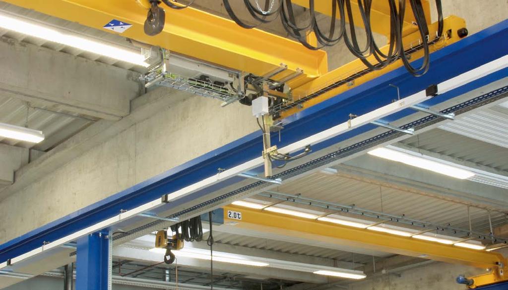
3 Enclosed conductor system KBH Content... Page Description of the Conductor system... 3 Technical description... 4 Technical data... 5 Jointing material, Hangers & End caps... 8 Brackets... 9 End feeds, Line feeds Line feeds Terminal Box Curves, Sealing strip & Cable glands for feeds Heating Contact sections, turntables & switches Transfer funnels & Transfer guides Content... Page Transfer guides & Conductor dead section Removing section Anti-Condensation section Expansion section Single Current collector Double collector & Tow arms Flexible tow arm Examples for ordering Spare part list Questionaire Notes System photo End cap KE Sliding hanger KGA Fixpoint hanger KFA End feed KKE conductor section Joint cap KVM Line feed as alternative Current collector KSW (Tow arm MGU / MGF) Description of the Conductor system The Vahle-Powerail KBH is a shock hazard protected conductor system for indoor and outdoor installations. The plastic housing can accommodate different copper profiles. Type KBHF: in 4- and 5-conductor version, with preassembled copper conductors and spring loaded connectors from 40 to 100 A. Type KBHS: in 4- and 5-conductor version, with preassembled copper conductors and bolted joints from 40 to 200 A. A compact design, corrosion resistance and an easy installation are the main characteristics. The KBH complies with VDE, european and international standards as well as accident prevention regulations. It is protected to IP 23 standards. The KBH can be supplied with sealing strip and heating system. The conductor system with sealing strip is protected to IP 24 standards and EN (0470, part 1) regulation. Collectors are touch proof only when fully entered into the conductor system. If there is the possibility to touch live parts by hand, ie. collectors that might leave the conductor system during operation, provide safety barrier or disconnect mains. This is valid only for a supply voltage exceeding 24 V AC or 60 VDC. If a conductor is used as N please note VDE 0100 part
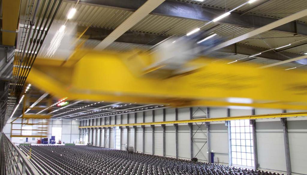
4 Technical description Applications For mobile power consumers like cranes, monorails, electric hoists, machine tools, automated storage and retrieval systems, lighting systems. Approvals UL-approved Housing Color grey, plastic housing for 4 or 5 conductors. Standard section 4 m. Other sections are available. The ground conductor is identified by international color code. Phase reversing prevented by design of the collector and housing. Higher number of conductors possible by combination of several conductor systems. Couplings Through plastic joint caps. Feed Sets Line feeds or end feeds. End caps The open ends of the conductor system are closed by end caps for KBHF and KBHS. Hangers Support bracket at the crane track (see page 9). Max. support distance of the conductor at following ambient temperatures: Indoor systems and roofed outdoor systems: 35 C = 2,00 m Indoor and outdoor systems with and without heating: 35 C = 1,33 m Cold storage: 0 C = 1,33 m Expansion during temperature fluctuation The Expansion sections are required to compensate the different expansions between copper conductors and steel- or concrete structures, in varying temperatures without interrupting electrical power. The different expansions between the plastic housing and the copper conductors will be compensated in every joint. Anti-condensation sections These sections are used for transfer of the Powerail to outdoor areas to avoid condensation. The conductor system is not separated electrically. Contact sections, turntables and switches Conductor sections for working areas and transfer applications see page 17 and 18. Sectionalizing Conductor dead sections are electrical interrupts of the conductor. Under normal operating conditions a cross over with collectors to switch the voltage off or on is only allowed with low power ratings (control current). The conductors can be seperated through air gaps (5 mm) or insulating pieces (35 mm). With the air gap the collector carbon bridges the gap, e.g. for mains. The insulating piece is longer than the carbon and each conductor section can be separated electrically, e.g. for control. Collectors The current collectors are made of re-inforced polyester fiberglass, for high strength and light weight. Spring loaded carbon brushes maintain uniform contact. Connecting cables and hinged or flexible towing arms included. With following system requirements double collectors have to be used: Transfers with switches and turntables low voltages, frequency controlled drives Transmission of data- and/or emergency stop signals high electrical loads The length of the collector cable may not exceed 3 m if the added overcurrent protection device is not designed for the load capacity of this cable. Please refer also to regulations VDE 0100, part 430 and EN (Note: this might happen in case of several collectors running in one system). Removing section for collectors Assembly and disassembly of the collector is possible at the end of the track as well as at the removing section. By opening and closing the sliders at the bottom of the conducor housing the collector can be mounted and demounted easily. Before opening the removing section the conductor system has to be without voltage. Safety advice It must be ensured that the arrangement of the conductor system provides minimum distances (0,5 m) between fixed and mobile plant parts (i.e. between conductor rails, collector trolleys and towing arms) so as to avoid the risk of pinching. Please note: For use in galvanizing and pickling plants, under agressive conditions and low voltage applications we would appreciate receiving detailled information,especially of the environmental conditions. For quotations and order processing including conductor systems with curves, dead sections, turntables, switches etc. we require your drawings or sketches. Please use our questionnaire, page 28. 4
5 Technical data Electrical values: Type max. continuous current Nominal voltage (UL) Dielectric strength Spec. resistance Surface resistivity Leakage resistance KBH 200 A (at 100% DC) 690 V (600 V) IEC kv/mm IEC x Ω/cm IEC Ω EN CTI 400 2,7 Mechanical properties: Type Flexible strength Tensile strength Temperature range (ambient): Combustibility: Resistance to chemicals: (at 45 C) KBH 75 N/mm 2 ± 10% 40 N/mm 2 ± 10% -30 C up to +60 C flame retardant DIN 4102 part 1 class B1; self extinguishing Gasoline, Mineral Oil, Grease, acid sulfur up to 50%, caustic soda up to 50% and hydrochloric acid up to 25%, concentrated Consider the voltage drop calculation to maintain the limits established by the motor manufacturers! AC: DC: ΔU = 3 x I x l x Z ΔU 1 =2 l x I x R ΔU 1 = Voltage drop [V] R = Resistance [Ω/1000 m] ΔU 2 = Voltage drop in % l = Power feed length [m] I = Ampere load [A] L = System length [m] l = L l = L/2 l = L/4 l = L/6 power feed located at the end of the system power feed located at the center of the system power feed located at both ends of the system power feed located at L/6 from each end of the system Z = Impedance [Ω/1000 m] V = Voltage rating [V] The total ampere load is determined from the nominal rated current of all motors working simultaneously on the same feed section of your electrification system. A diversity factor of 0,5-0,9 can be considered. The conductor size and/or number of feed points should be increased or booster cables should be used in parallel in case the drop is exceeding the limitations. 5
 contro line KBHF 4 / 40... HS 4 52 45 40 3 x 10 10 - - 690 KBHF 4 / 40.")
 5 52 45 40 - - - 5 x 10 690 KBHF 5 / 63... HS 5 81 70 63 3 x 14 14 14-690 KBHF 5 / 100... HS 5 129 112 100 3 x 26 26 26 (3) - 690 KBHS KBHS 4 / 40.")
6 Technical Data A rechte Seite A left side right side left side right side A A KBHF with spring loaded connectors KBHS with bolted joints Type (1) KBHF HS with PE SS without PE No.of conductors Max.continuous current A at 35 C Copper cross section mm 2 L1 L2 L3 60 % DC 80 % DC 100 % DC L1 L2 L3 N / 5 (2) contro line KBHF 4 / HS x KBHF 4 / SS (5) x KBHF 4 / HS x KBHF 4 / HS x KBHF 5 / HS x KBHF 5 / SS (5) x KBHF 5 / HS x KBHF 5 / HS x (3) KBHS KBHS 4 / HS x KBHS 4 / SS (5) x KBHS 4 / HS x KBHS 4 / HS x KBHS 4 / HS x KBHS 4 / HS x KBHS 4 / HS x KBHS 5 / HS x KBHS 5 / SS (5) x KBHS 5 / HS x KBHS 5 / HS x (3) KBHS 5 / HS x (3) KBHS 5 / HS x (3) KBHS 5 / HS x (3) (1)... Suffix types e.g. 2 m KBHF 4/63 with PE KBHF 4/63-2 HS Order-No , shorter legths are made up from the next larger standard length. (2) In case of using a conductor as N see page 3. (3) 5th. Conductor max. 80 A at 100% DC. (4) Nominal voltage UL= 600 V (5) control line Nominal voltage V (4) 6
7 Technical Data A A KBH 4 conductors A A KBH 5 conductors safety web safety web N/5 L1 (2) L3 (4) L1 (2) L3 (4) 70 yellow (dark grey) 70 yellow (dark grey) L2 (1) (3) green (dark grey) L2 (1) (3) green (dark grey) 9 9 Numbers in paranthesis apply to control line Leakage distance mm Impedance at 50 Hertz and 20 C Ω / 1000 m Widerstand bei 20 C Ω/1000 m Weight kg/m Order-No. (1) 33 1,724 1,717 1, ,724 1,717 1, ,258 1,249 1, ,702 0,687 1, ,724 1,717 1, ,724 1,717 1, ,258 1,249 1, ,702 0,687 2, ,724 1,717 1, ,724 1,717 1, ,258 1,249 1, ,702 0,687 2, ,568 0,549 2, ,376 0,351 2, ,283 0,255 3, ,724 1,717 1, ,724 1,717 1, ,258 1,249 1, ,702 0,687 2, ,568 0,549 2, ,376 0,351 2, ,283 0,255 3, The last number of the order specifies the section length. Please suffix the order number with 1, 2, 3, 4. Ground = PE 7


 Weight kg KFA 0,132 600 007 KFA / K 0,132 600 398 130 89 17 End cap left and right")
8 Jointing material, Hangers & End caps 130 Joint cap, self locking ready installed Type Weight kg Order-No. KVM 0, M8 142 max Sliding hanger Sliding hanger at conductor section Type (1) Weight kg Order-No. KGA 0, KGA / K 0, Fixpoint hanger Fixpoint hanger at conductor section Type (1) Weight kg Order-No. KFA 0, KFA / K 0, End cap left and right version End cap ready installed Type Weight kg Order-No. KE 0, (1).../K with stainless screws All steel metal components 8
9 Brackets A-A Ansicht ohne X-Träger 32 L 25 A M8 support bracket max fixing claw suitable for D = 6 15 mm 45 D fixing claw A Tow arm level X 15 B R = 10xD D X A - A A-A Ansicht ohne X-Träger L 25 M8 max.48 D A fixing claw suitable for D = mm 45 B A Arrangement EHK with small fixing claw Ø 9 Attention! Make sure that hoist wheels have enough clearance. Use small claw if necessary. D Specify dimension D small fixing claw Select next larger size bracket when your -beam dimension B is more than 170 upto 300 mm. - rail of EHK is identical to type S 1, Cat. 8 a Type X mm L mm B max. mm Weight kg Order-No. standard version Order-No. with small fixing claw EHK , EHK , EHK , EHK , EHK , EHK , EHK , EHK ,

 End feed comes loose without conductor")
10 End feeds, Line feeds End feed (up to 63 A) End feed comes loose without conductor section. It can be mounted at the left or right hand side. Electrical connection with customer supplied cable shoes to M6 terminals. Max. connecting cross section 10 mm 2. M M 32 (below) Type Weight kg Cable gland (Dimensions see page 13) Order-No. KKE 4 / HS 0,218 M KKE 5 /40 63 HS 0,230 M KKE 4 / 40 SS 0,196 M KKE 5 / 40 SS 0,208 M End feed (uo to 100 A) End feed comes loose without conductor section. It can be mounted at the left or right hand side. Electrical connection with customer supplied cable shoes to M6 terminals. Max. connecting cross section 35 mm Type Weight kg Cable gland (Dimensions see page 13) Order-No. KKE 4 / HS 0,570 M 32 oder M 50 (1) KKE 5 / HS 0,610 M 32 oder M 50 (1) Line feed (at joint, A) KSE type comes loose without conductor section. It can be mounted at any joint. Electrical connection with customer supplied cable shoes to M6 terminals Typ Gewicht kg Cable gland Order-No. (Dimensions see page 13) KSE 4 / 40 HS 0,756 M KSE 4 / 63 HS 0,776 M KSE 5 / 40 HS 0,812 M KSE 5 / 63 HS 0,832 M KSE 4 / 40 SS 0,756 M KSE 5 / 40 SS 0,812 M Line feed (at joint, 100 A) KSE type comes loose without conductor section. It can be mounted at any joint. Electrical connection with customer supplied cable shoes to M6 terminals Type Weight kg Cable gland Order-No. (Dimensions see page 13) KSE 4 / 100 HS 0,908 M KSE 5 / 100 HS 0,964 M Feeds in the curve area on request. (1) Both cable glands are attached to the packing unit. 10

11 Line feeds Line feed (incl. 1 m section, A) With spring loaded connector. Electrical connection with customer supplied cable shoes to M6 terminals. a b Type Weight kg Dimension Cable gland Order-No. a b (Dimensions see page 13) KEF 4 / 40 HS 2, M KEF 4 / 63 HS 2, M KEF 5 / 40 HS 2, M KEF 5 / 63 HS 2, M KEF 4 / 100 HS 2, M KEF 5 / 100 HS 3, M KEF 4 / 40 SS 2, M KEF 5 / 40 SS 2, M Line feed (incl. 1 m section, A) With bolted joints. Electrical connection with customer supplied cable shoes M6 terminals to 100 A, with M8 terminals to 125 A. a b Type Weight kg Dimension Cable gland Order-No. a b (Dimensions see page 13) KES 4 / 40 HS 2, M KES 4 / 63 HS 2, M KES 5 / 40 HS 2, M KES 5 / 63 HS 2, M KES 4 / 100 HS 2, M KES 4 / 125 HS 3, M KES 5 / 100 HS 3, M KES 5 / 125 HS 3, M KES 4 / 40 SS 2, M KES 5 / 40 SS 2, M Feeds in the curve area on request. 11

12 128 Line feed & Terminal Box Line feed including 1m section ( A) with 2m single cores Electrical connection with customer supplied cable shoes to M 6 terminals. See below Type Weight kg Cable cross section in sqmm / Diam. in mm Order-No. L1 L3 Ground N / 5 KELS 4 / 125 HS 8, / / KELS 4 / 160 HS 9, / / KELS 4 / 200 HS 11, / / KELS 5 / 125 HS 9, / / / KELS 5 / 160 HS 10, / / / KELS 5 / 200 HS 12, / / / A 400 B 120 Terminal Box (for KELS, A) Electrical connection with customer supplied cable shoes. Clamping range mm 2. View,,A Input of the single cores of the KELS (a.m.) View B with M 63 (Dimensions see page 13) 360 (1) Type Weight kg for line feed Order-No. ZK 1 5,030 KELS 4 / 125 HS ZK 2 5,040 KELS 4 / HS ZK 3 5,370 KELS 5 / 125 HS ZK 4 5,380 KELS 5 / HS Feeds in the bow area on request. (1) Fixing borings ø 7 mm at the bottom of the box. 12
13 Curves, Sealing strip & Cable glands for feeds Curves Production corresponding to customer drawing 54 safety web Min. horizontal bending radius A = 600 mm 160 A = 1000 mm 200 A = on request max. ) 120 min. bending radius, vertical = 2000 mm max. curved length = 3600 mm 70 VRU VRO L1 (2) L2 (1) N/5 L3 (4) (3) yellow (dark grey) green (dark grey) 9 HR for SA HR for SI Horizontal curve for SI and SA SI = Safety-web inside SA = Safety web outside Vertical curve for VRO and VRU VRO = Vertical radius upwards VRU = Vertical radius downwards Safety web will be mounted in direction of track. Changes in measurements of curves have to be mentioned for replacement orders. 2 sealing strips Sealing strip (including accessories) Type Order-No. Sealing strip (1) Fixing clamp for sealing strip (1 per end) Coupling for sealing strip (2 for each joint) Mounting glider for sealing strip Sealing strip slide plate for collectors KSW Cable glands for feeds for type Cable gland for cable diam. in mm Power rating in A Page KKE M HS 10 KKE M / 63 HS 10 KKE M SS 10 KSE / KEF / KES M HS / SS 10 und 11 KSE / KEF / KES M HS 10 und 11 KSE / KEF / KES M HS 10 und 11 KES M HS 11 ZK 1 4 (Seite B) M / 160 / 200 HS 12 (1) The max. single length is 40 m long. For further distances are joint laces necessary. For each meter system length have 2 m sealing strip to beordered. The delivery will be in pairs. 13
14 Heating Type Resistance (2) Order-No. Heating cable: H 0,15 0,15 Ω/m Heating cable: H 0,20 0,20 Ω/m Heating cable: H 0,32 0,32 Ω/m Heating cable: H 0,38 0,38 Ω/m Heating cable: H 0,48 0,48 Ω/m Heating cable: H 0,60 0,60 Ω/m Heating cable: H 0,81 0,81 Ω/m Heating cable: H 1,00 1,00 Ω/m Heating cable: H 1,44 1,44 Ω/m Heating cable: H 2,00 2,00 Ω/m Heating cable: H 3,00 3,00 Ω/m We recommend a heating system for outdoor installations and conductor systems in humid plants. The heating consists of two heating cables which are arranged according to the illustration beside. Attention: Switch on heating system below + 5 C ambient temperature. The type of heating cable has to be calculated: heat output per heating cable between W/m. (1) For longer heating distances the total length has to be devided into different heating sections. For shorter heating distances to feed with lower secondary voltage via transformer. Construction of the heating cable: Heating resistor made of CrNi (different conductors) Isolation of heating cable PTFE (Teflon) Nickel-plated copper netting Sheath PTFE-Isolation Outer diameter: 3,7mm - 4,3 mm N(W/m) 400V H3.0 H2.0 H H1.0 H0.81 H0.6 H0.48 Heating capacity Watt/m: N' = U 2 R L 2 U = Supply voltage (Volt) R = Resistance of heating cable (Ohm/m) L = Lenght of heating section (m) l(m) N(W/m) 230V H3.0 H2.0 H1.44 H1.0 H0.81 H0.6 H H0.38 H0.32 H0.2 H0.15 (1) Arrangement of heating cable (2) Deflection ± 2,5% l(m) 14
15 Heating Layout examples (depending on system situation) a) 2 heating circuits heating circuit 1 heating circuit 2 b) 1 heating circuit grid 230 or 400 VAC grid 230 or 400 VAC c) 2 heating circuits 1-core cable> 2.5 mm 2 installed by customer Attention: max. 25 W/m per heating cable Terminal box grid 230 or 400 VAC Terminal boxes for heating Type Version Cable gland Measurements see page 13 Order-No. Teminal box left end M Teminal box right end M Teminal box lene feed 2 x M set material for connecting clamps For each end feed box 2 sets of material for connecting ends are required. For line feed you need 4 sets of material for connection ends. Order for 60 m powerail - example c) 1) 122 m heating cable type H 2,0 (2 x 60 m and 2 x 1 m additional) Voltage 400 V, two heating circles parallel heating capacity as per above mentioned diagramm 2 x 22 W/m at 60 m 2 x 22 W/m ~2640 W = 2,64 kw ) 1x Junction box left end 1x Junction box right end 3) 4x sets of material for connection ends. Switch gear assembly and temperature control unit as per customers inquiry. Fuses, cables etc. have to be provided by the customer. 15
16 Contact sections, turntables & switches w/o cond. (1) Contact area (1) w/o cond. Contact section (1) Line feed Powerail Track Transfer funnel w/o cond. (1) Contact area (1) w/o cond. Turntable Transfer guide, oblique cut Turntable frame Track b a Line feed max. 20 mm Powerail Switch Transfer guide Transfer guide a Line feed a max. 20 mm Please submit drawings of transfer applications. Specify dimensions a, b, c, R and angle ( = max. 50 ) Track Switch frame R Transfer guide, oblique cut Powerail Max. 20 mm air gap between transfer guides. To create all parts for contact sections, turntables and switches we require detailed construction drawings. α (1) Contact sections must not be activated before collectors are fully engaged. c 16


17 Transfer funnels & Transfer guides Transfer funnel Conductor system should not be activated before the collectors carbons have complete contact with the conductors. 140±10 Offset: max. 10 mm horizontal max. 10 mm vertical Max. speed for crossover of the current collector 60 m/min. Hints for dimensioning the left-and right hand version refer to page 6 and w/o cond. (2) 500 Type (1) Weight kg Order-No. left version right version KET 4 / HS 1, KET 4 / HS 1, KET 4 / HS 1, KET 5 / HS 1, KET 5 / HS 1, KET 5 / HS 2, KET 4 / SS 1, KET 5 / SS 1, Transfer guides, straight Necessary with all types of double collectors or 2 single collectors. 50±10 Staggered arrangement of the transfer guides to each other: max. 5 mm horizontal max. 3 mm vertical Max. speed for crossover of the current collector 80 m/min. Hints for dimensioning the left-and right hand version refer to page 6 and w/o cond. 350 Type (1) Weight kg Order-No. left version right version KÜ 4 / HS 1, KÜ 4 / HS 1, KÜ 4 / HS 1, KÜ 5 / HS 1, KÜ 5 / HS 1, KÜ 5 / HS 1, KÜ 4 / SS 1, KÜ 5 / SS 1, (1) Add types e.g. KET 4/ HS Left hand version KET 4/ L HS Order-No (2) Corresponding to the center of collector 17
 and angle to be specified by customer Max.")

18 Transfer guides & Conductor dead section Transfer guides, oblique Necessary with all types of double collectors or 2 single collectors. 90±10 Staggered arrangement of the transfer guides to each other: max. 5 mm horizontal max. 3 mm vertical Measurements (oblique) and angle to be specified by customer Max. speed for crossover of the current collector 80 m/min. Hints for dimensioning the left-and right hand version refer to page 6 and w/o cond. 350 Type (1) Weight kg Order-No. left version right version KÜS 4 / HS 1, KÜS 4 / HS 1, KÜS 4 / HS 1, KÜS 5 / HS 1, KÜS 5 / HS 1, KÜS 5 / HS 1, KÜS 4 / SS 1, KÜS 5 / SS 1, (1) Add types e.g. KÜS 4/ HS Left hand version KÜS 4/ L HS Order-No Conductor dead section 35 mm isolating piece Please advise us which conductors should be disconnected (see Page 6 and 7). The dead section comes factory assembled. Picture shows a isolating piece. Air gap 5 mm Isolating piece 35 mm Type Ordeer-No. Type Order-No. KTL KTI KTL KTI KTL KTI KTL KTI KTL KTI
19 Removing section Removing section (incl. 1m conductor section) with special bolted joints for KBHF and KBHS on both ends. Assembly and disassembly of the collector is possible at the end of the track as well as at the removing section. By opening and closing the sliders at the bottom of the removing section housing the collector can be mounted and demounted easily. Before opening disconnect mains. 83 A - A close 9 74 A - A open 110 The removing section does not disconnect the conductor system electrically A A For single collectors Type Weight kg Order-No. KAT 4 / HS 3, KAT 4 / 160 HS 3, KAT 4 / 200 HS 4, KAT 5 / HS 3, KAT 5 / 160 HS 4, KAT 5 / 200 HS 4, KAT 4 / 40 SS 3, KAT 5 / 40 SS 3, For double collectors Type Weight kg Order-No. KATD 4 / HS 4, KATD 4 / 160 HS 4, KATD 4 / 200 HS 5, KATD 5 / HS 4, KATD 5 / 160 HS 4, KATD 5 / 200 HS 5, KATD 4 / 40 SS 4, KATD 5 / 40 SS 4,

20 Anti-Condensation section Anti-condensation section with special bolted joints for KBHF and KBHS at both ends Application of Anti-condensation section The anti-condensation section will be used where conductor systems are passing from indoor to outdoor, preventing condensation of the outside mounted conductor section. The warm air from indoors can escape through the anti condensation section (see sketch). The anti-condensation section does not interrupt the conductor system electrically. Additional feeds are not required. End cap Anti-Condensation Section Line feed conductor system Assembly The anti-condensation section is to be placed directly (0,5m - 1m max.) at the transfer point from indoor to outdoor. See sketch. Crane runway 0,5-1 m max. 125 m Fixpoint hanger X max. 125 m 0,5-1 m Outdoor Indoor Outdoor Type Weight kg Order-No. KBT 4 / HS 3, KBT 4 / 160 HS 4, KBT 4 / 200 HS 4, KBT 5 / HS 4, KBT 5 / 160 HS 4, KBT 5 / 200 HS 5, KBT 4 / 40 SS 3, KBT 5 / 40 SS 4,
21 Expansion section Expansion section The Expansion sections are required to compensate the different expansions between copper conductors and steel- or concrete structures, in varying temperatures without interrupting electrical power a 500 a 500 Expansion joints are used when the conductor length between feeds, curves, switches or other fix points is exceeding 20 m. Max. length during differences in temperature: Δ t 90 C (-30 C bis +60 C) install one expansion joint per 100 m. An additional expansion joint every 100 m. Arrangement of fixpoints according to sketches. The remaining conductor sections have to be arranged in sliding hangers. Additional feeds or current collectors are not required as the expansion-sections do not interrupt electrical power. Assembly The gap dimension a is 75 mm and is valid for an ambient temperature of -10 C to +35 C during installation. Fixpoint hanger Line feed End cap Expansion section X X crane runway max. 100 m Fixpoint hanger conductor system Expansion section Track X Conductor system max. 125 m X X above 20 m to max. 100 m X Type Weight kg Order-No. KD 4 / HS 4, KD 4 / 160 HS 4, KD 4 / 200 HS 5, KD 5 / HS 4, KD 5 / 160 HS 5, KD 5 / 200 HS 5, KD 4 / 40 SS 4, KD 5 / 40 SS 4,

 17,0 630 066 KSW 5 / 25 1 HS 0,634 5 25 14,0 600 098 KSW 5 / 40 1 HS 0,771 5 40 17,0 600")

22 Single Current collector 170 Collector KSW max. speed 150 m/min. For conductor systems with sealing strip up to 100 m/min. Connecting cable: for 25 A with 2,5 mm 2 /core for 40 A with 4,0 mm 2 /core for 60 A with 6,0 mm 2 /core 1 m long, longer cables on request. 119 Cleaning collector on request. Order example for a 2 m long cable Order-No for collector KSW 4/40-2 HS Type weight kg No. of conductors Power rating at 60 % DC in A approx. diam. of connecting-cables in mm Order-No. KSW 4 / 25 1 HS 0, , KSW 4 / 40 1 HS 0, , KSW 4 / 60 1 HS 0, (1) 17, KSW 5 / 25 1 HS 0, , KSW 5 / 40 1 HS 0, , KSW 5 / 60 1 HS 0, (1) 19, KSW 4 / 25 1 ST 0, , KSW 5 / 25 1 ST 0, , Collector KSWS max. speed 250 m/min. For conductor systems with sealing strip up to 100 m/ min. 272 Connecting cable: for 25 A with 2,5 mm 2 /core for 40 A with 4,0 mm 2 /core for 60 A with 6,0 mm 2 /core 1 m long, longer cables on request. 119 Order example for a 2 m long cable Order-No for collector KSWS 5/40-2 HS Type Weight kg No. of conductors (1) at 40% DC Power rating at 60 % DC in A approx. diam. of connecting-cables in mm Order-No. KSWS 4 / 25 1 HS 0, , KSWS 4 / 40 1 HS 0, , KSWS 4 / 60 1 HS 0, (1) 17, KSWS 5 / 25 1 HS 0, , KSWS 5 / 40 1 HS 0, , KSWS 5 / 60 1 HS 1, (1) 19, KSWS 4 / 25 1 ST 0, , KSWS 5 / 25 1 ST 0, ,
 Also for conductor systems with sealing strip up to 100 m/min.")


 6,0 mm 2 /core 1 m long, longer cables on request.")


 19,0 600 415 DKSW 4 / 50 1 ST 1,010 4 50 11,0 600 117")
 A A Version with tube (2) by customer A A 100 53 Tow arm Installation options of 30 mm")
23 Double collector & Tow arms Double collector DKSW (max. speed 150 m/min.) Also for conductor systems with sealing strip up to 100 m/min. The double collectors are supplied as an assembly kit consisting of 2 collectors (KSW) and a connecting bar with mounting material. For the collector KSWS there are no double collectors available 2 single collectors must be used instead Connecting cable: for 50 A with (2x) 2,5 mm 2 /core for 80 A with (2x) 4,0 mm 2 /core for 120 A with (2x) 6,0 mm 2 /core 1 m long, longer cables on request. 121 Order example for 2 m long cables Order-No for collector DKSW 5/80-2 HS Type Weight kg No. of conductors Power rating at 60 % DC in A approx. diam. of connecting-cables in mm Order-No. DKSW 4 / 50 1 HS 1, , DKSW 4 / 80 1 HS 1, , DKSW 4 / HS 1, (1) 17, DKSW 5 / 50 1 HS 1, , DKSW 5 / 80 1 HS 1, , DKSW 5 / HS 1, (1) 19, DKSW 4 / 50 1 ST 1, , DKSW 5 / 50 1 ST 1, , A A Version with square hollow profile (without adapter plate) A A Version with tube (2) by customer A A Tow arm Installation options of 30 mm square-, hollow profile or tube with mm Type Weight kg Order-No. MGU 0, MGU / K (3) 0, M to center of tube slotted hole 9 x 30 Tow arm Installation option for plane surface ± 10 Type Weight kg Order-No. MGF 0, MGF / K (3) 0, (1) At 40% DC (2) For assembly use enclosed adapter plate (3) Stainless steel 23

24 Flexible tow arm slotted hole 9 x Flexible tow arm Fexible support type for single collector for installations with transfer funnels type KET (see page 13). Measurements for installation see below. If you are going to use the flexible towing arm in system with curves please contact us. 138 Type Weight kg Order-No. KFMHN 0, Arrangement of a flexible tow arm KFMHN with collector type KSW 54 L2 L1 70 A A ca. 60 (¹) Ø 10 6, fixing side max. horizontal offset 10 mm max. vertical offset 10 mm 305 (1) To be fixed during installation. 24
25 Examples for ordering Installation length of 64 m KBH... (configuration see page 6 and 7) Quantity Article 16 conductor section, 4 m long 15 conductor section, 4m long 1 conductor section, 3m long KBHF 4 / 63 HS with end feed KBHF 5 / 100 HS mit with line feed KBHS 5 / 160 HS with line feed incl. 1m conductor section Type Order-No. Type Order-No. Type Order-No. KBHF 4/63-4 HS KBHF 5/100-4 HS KBHS 5/160-4 HS KBHS 5/160-3 HS End feed KKE 4/40-63 HS Line feed - - KSE 5 / 100 HS Line feed 1m long KELS 5/160 HS End cap KE End cap - - KE KE Joint cap KVM Joint cap - - KVM Joint cap KVM Fixpoint hanger KFA KFA KFA Sliding hanger KGA KGA KGA Current collector KSW 4/40-1 HS KSW 5/40-1 HS KSW 5/40-1 HS Tow arm MGU MGU MGU
26 Examples for ordering Installations with curves as per customer drawing 41,075 m conductor system KBHF 4/63 consisting of: Quantity Article KBHF 4 / 63 KBHS 5/63 7 Conductor system, 4m long 1 Conductor system, 4 m long for 1 x 3500 mm short length 1 Conductor system, 3 m long for 1 x 2610 mm short length 1 Conductor system, 2 m long for horizontal curve 45, R = 2100 mm, L = 1648 mm, SA 2 Conductor system, 3 m long for horizontal curve 2 x 45, R = 2700 mm, L = 2121 mm, SI Type Order-No. Type Order-No. KBHF 4/63 4 HS KBHS 5/63 4 HS KBHF 4/63 4 HS KBHS 5/63 4 HS KBHF 4/63 3 HS KBHS 5/63 3 HS KBHF 4/63 2 HS KBHS 5/63 2 HS KBHF 4/63 3 HS KBHS 5/63 3 HS End feed KKE 4/40 63 HS KKE 5/40 63 HS Expansion section KD 4/ HS KD 5/ HS Joint cap KVM KVM Fixpoint hanger KFA KFA Sliding hanger KGA KGA End cap KE KE , 075 m Schleifleitung KBHS 5 / 63 bestehend aus: 1 Current collector KSW 4/40 1 HS KSW 5/40 1 HS Tow arm MGF MGF End feed R = L = 4242 X R = conductor system X X crane runway Expansion section according to installation temperature from -10 C to 35 C Fixpoint hanger (1) X L = End cap (1) Rest of conductor system to be installed with sliding hangers 26
27 Spare part list Spare part list for conductor system Type KBHF KBHS Order-No. Order-No. Joint cap (pair) Spring loades connector A Bolted joints A Bolted joints 200A Neoprene sealing strip, in pairs (max. length 40m each) Coupling for sealing strip, in pairs (for lengths < 40m each) Fixing clamp for sealing strip (1 per end) Mounting glider for sealing strip (> 10m system length) Feed terminal for end feed (40/63A) Feed terminal for line feed (lateral) Feed terminal for line feed (on top, 5th conductor) Spare part list for current collector Type KSW/DKSW KSWS Order-No. Order-No. Carbon brush phase (lateral) Carbon brush 5th conductor (top) Carbon brush ground (lateral PE) Carbon pressure spring (standard), suitable for all carbon brushes Connecting bar for double collector DKSW Assembly kit (to convert KSW KSWS) Sealing strip slide plate for collectors KSW
28 Questionaire Company: Fon: Date: Fax: Internet: 1. Number of conductor system installations: 2. Type of equipment to be powered: 3. Operating voltage: Volt Frequency: Hz Three phase voltage: AC voltage: DC voltage: 4. Track lenght: 5. Number of conductors: neutral: control: ground: 6. Mounted position of conductor system: Conductor system pendant, collector cable facing to the bottom Conductor system pendant, lateral payout of conductor cable (1) Support distance m (max. 2m) other: 7. Number of consumers per system: 8. Indoor: Outdoor: 9. Other operating conditions (humidity, dust, chemical influence, etc.) 10. Ambient temperature: C min. C max. 11. Hall expansion joints: pieces expansion min.: expansion max.: 12. Position and number of feeding points (1) : 13. Position and number of isolating sections (e.g. for maintenance) (1) : 14. How will the conductor be arranged? (1) : 15 Brackets required: yes no c/c distance beam/conductor system: 16. Travel speed: m/min. in curves: m/min. at transfers: m/min. 17. Max. voltage drop from the conductor system feed point to the consumer considering starting current. 18. Power consumption of the individual consumer loads: Motor data Hoist motors Auxiliary hoist Long travel Cross travel Power kw Crane 1 Crane 2 Nominal current Starting current Type of Power Nominal current Starting current Type of Motors (2) kw Motors A cos ФN % DC A cos ФA A cos ФN % DC A cos ФA (2) Mark with * those motors which can run simultaneously. Mark with those motors which can start up simultaneously. Further remarks: (1) For curved tracks, powerail with isolating sections etc., we require sketches to enable us to prepare a quotation (2) Use: K for squirrel cage motor, S for slipring motor, F for frequency controlled motor We reserve all rights to make alterations in the interests of further development Please copy and fill in the questionnaire Signature 28
29 29
30 Notes 30
31 Notes 31
32 Products and Service Catalog No. 1 Open conductor systems Open conductor systems 1a 2 Insulated conductor systems U10 2a FABA 100 2b U15, U25, U35 2c U20, U30, U40 2d 3 Compact conductor systems VKS 10 3a VKS - VKL 3b 4 Enclosed conductor systems KBSL - KSL 4a KBH 4b MKH 4c LSV - LSVG 4d 5 Contactless power supply Contactless power supply (CPS ) 5a 6 Data transmission VAHLE Powercom 6a Slotted Microwave Guide (SMG) 6b 7 Positioning systems VAHLE APOS 7a VAHLE APOS Optic 7b 8 Festoon systems and cables Festoon systems for -tracks 8a Festoon systems for flat cables on -track 8b Festoon systems for round cables on -track 8c Festoon systems for -track 8d Cables 8e 9 Reels Spring operated cable reels 9a Motor powered cable reels 9b 10 Other Battery charging systems 10a Heavy enclosed conductor systems 10b Tender 10c Contact wire 10d Assemblies / Commissioning Spare parts / Maintenance service /en /13 certified by DQS according to Din EN ISO 9001:2008 OHSAS 18001:2007 (Reg. Nr QM 08/BSOH) Kamen/Germany +49(0)2307/704-0 info@vahle.de ELECTRIFICATION SYSTEMS
POWERAIL ENCLOSED CONDUCTOR SYSTEM KBH
 POWERAIL ENCLOSED CONDUCTOR SYSTEM KBH POWERAIL KBH Contents Page Contents Page System photo 2 Removing sections, Conductor dead sections 14 General 2, 3 Anti-condensation sections, Expansion sections
POWERAIL ENCLOSED CONDUCTOR SYSTEM KBH
 POWERAIL ENCLOSED CONDUCTOR SYSTEM KBH POWERAIL KBH Contents Page Contents Page System photo 2 Removing sections, Conductor dead sections 14 General 2, 3 Anti-condensation sections, Expansion sections
MACHT STROM MOBIL. Enclosed conductor system KBH SYSTEMS IN MOTION
 MACHT STROM MOBIL Enclosed conductor system KBH SYSTEMS IN MOTION 4b/en 2016 2 Enclosed conductor system KBH Inhalt Enclosed conductor system KBH... 3 Technical description... 4 Technical data... 6 Jointing
COMPACT CONDUCTOR SYSTEMS VKS 10
 COMPACT CONDUCTOR SYSTEMS VKS 10 POWERAIL ENCLOSED CONDUCTORS VKS 10 CONTENTS Page General 2, 3 Planning guide 4 Application photos 5 Technical data, standard sections 6, 7 Curved sections and jointing
POWERAIL ENCLOSED CONDUCTOR SYSTEM VKS 10
 POWERAIL ENCLOSED CONDUCTOR SYSTEM VKS 10 POWERAIL ENCLOSED CONDUCTORS VKS 10 CONTENTS Page General 2, 3 Planning guide 4 Technical data, standard sections 6, 7 Curved sections 8 Jointing material 8 Hangers
POWERAIL CONDUCTOR SYSTEMS MKLD MKLF MKLS
 POWERAIL CONDUCTOR SYSTEMS 19 12 POWERAIL INDEX Page Powerail versions 3 Basic description 3 Technical data 3 Powerail types, cat. nos. and weights 4 Engineering data and configurations 5 Standard sections,
POWERAIL ENCLOSED CONDUCTOR SYSTEM VKS 10
 POWERAIL ENCLOSED CONDUCTOR SYSTEM VKS 10 POWERAIL ENCLOSED CONDUCTORS VKS 10 CONTENTS Page General 2, 3 Planning guide 4 Technical data, standard sections 6, 7 Curved sections 8 Jointing material 8 Hangers
Compact Conductor System VKS10 SYSTEMS IN MOTION
 Compact Conductor System VKS10 SYSTEMS IN MOTION 3a/en 2016 Content General...3 System diagram...5 Sections...6 Pole configuration...7 Curved sections...8 Fixpoint hanger...9 End cap...9 Sliding hanger...9
Multi Support Profile VMT SYSTEMS IN MOTION
 Multi Support Profile VMT SYSTEMS IN MOTION 3c/en 2013 2 Multi Support Profile (VMT) Content The VAHLE solution for automation...3 System layout...4 Technical data...4 VMT - Multi Support Profile...5 Joint
MACHT STROM MOBIL. Battery Charging Systems
 MACHT STROM MOBIL Battery Charging Systems 10a/en 15 2 Battery Charging Systems Content...Seite General...3 Models...4 General installation instructions...7 The operation of Automatic Guided Vehicles (AGVs)
Enclosed Conductor System MKH SYSTEMS IN MOTION
 MACHT STROM MOBIL Enclosed Conductor System MKH SYSTEMS IN MOTION 4c/en 4c/de 2016 2015 Enclosed conductor system MKH Content Description of the conductor system... 3 Technical Data... 5 Technicall data
Energy Supply Systems
 Energy Supply Systems SINGLE POLE INSULATED CONDUCTOR RAIL 815 100 amps KAT0815-0001b-E Conductor rail system in a high bay storage Slip ring with conductor rail system in a stretch-foil packing machine
INSULATED CONDUCTOR SYSTEMS U10
 INSULATED CONDUCTOR SYSTEMS U10 INSULATED CONDUCTORS U 10 Index Page Basic description 3 Insulated conductors 4 Feed-in joint splice 5 Expansion section 5 Isolating assembly 5 Transfer guide 6 Compact
4 pole insulated conductor rails ULA 35A, 50A, 80A, 100A
 Table of contents General information... 3 Elements of the conductor rail supply line... 3 Innovative connection method... 3 Technical properties... Construction of the line section... Line section...
4 pole insulated conductor rails UNILIFT-ULA 35A, 50A, 80A, 100A
 2 Table of contents General information... 4 Elements of the conductor rail supply line... 4 Innovative connection method... 5 Technical properties... 6 Construction of the line section... 6 Line section...
Energy Supply Systems
 Energy Supply Systems MULTIPOLE CONDUCTOR RAIL 831 10-125 amps KAT0831-0001b-E 13 pole multipole conductor rail in 33 package distribution centres of the postal service (Post AG) 9 pole multipole conductor
VAHLE POWERCOM 485. Digital Data Transmission System
 VAHLE POWERCOM 485 Digital Data Transmission System 19 12 VAHLE POWERCOM 485 GENERAL INFORMATION VAHLE POWERCOM 485 Digital Data Transmission using VAHLE Conductor Systems VAHLE POWERCOM 485 is the latest
4 pole insulated conductor rails ULA 35A, 50A, 80A, 100A
 Table of contents General information... 3 Elements of the conductor rail supply line... 3 Innovative connection method... 3 Technical properties... Construction of the line section... Line section...
MACHT STROM MOBIL. Spring Operated Cable Reels
 MACHT STROM MOBIL Spring Operated Cable Reels 9a/en 2013 2 Spring Operated Cable Reels Content...Page Spring operated cable reels...3 Reel selection charts...5 Typical applications...6 Model explanation...7
BATTERY CHARGING SYSTEMS. for Automatic Guided Vehicles
 BATTERY CHARGING SYSTEMS for Automatic Guided Vehicles 19 12 GENERAL INFORMATION The operation of Automatic Guided Vehicles (AGVs) requires high utilization of these vehicles in order to achieve an optimum
POWERAIL ENCLOSED CONDUCTOR SYSTEMS VKS VKL
 POWERAIL ENCLOSED CONDUCTOR SYSTEMS VKS VKL 19 12 POWERAILS VKS & VKL INDEX VKS VKL Basic description 3, 4 3, 4 Layout planning 5 5 Engineering data, Powerail standard sections 6, 7 23 Powerail curves
MACHT STROM MOBIL. Insulated Conductor Systems U10
 MACHT STROM MOBIL Insulated Conductor Systems U10 2a/en 2014 Table of Contents Basic description...2 Technical Data...4 Joint Feed...5 Feed Terminal...5 Isolating Assembly...5 Distance Bracket...5 Expansion
INSULATED CONDUCTOR SYSTEMS U 20 U 30 U 40
 INSULATED CONDUCTOR SYSTEMS U 20 U 30 U 40 INSULATED CONDUCTORS U 20 U 30 U 40 INDEX U 20 U 30 U 40 Page Page Page Basic description 4 4 4 Selection of conductors 5-10 5-10 5-10 Conductors 11 24 34, 35
VAHLE POWERCOM 485. Digital Data Transmission System
 VAHLE POWERCOM 485 Digital Data Transmission System 19 12 VAHLE POWERCOM 485 GENERAL INFORMATION VAHLE POWERCOM 485 Digital Data Transmission using VAHLE Conductor Systems VAHLE POWERCOM 485 is the latest
POWERAIL ENCLOSED CONDUCTOR SYSTEMS KBSL KSL KSLT
 POWERAIL ENCLOSED CONDUCTOR SYSTEMS KBSL KSL KSLT POWERAILS KBSL KSL KSLT INDEX Page Page Powerail versions (Photos) 2 Transfer funnels 14 Basic description 2, 3 Anti-condensation section 15 Technical
Multipole Conductor Rail MultiLine Program 0831
 Multipole Conductor Rail MultiLine Program 0831 Contents Description / Technical Data Description....2 Technical Data....3 Conductor Rails Rails complete with pre-mounted Connector...4 Power Feeds....5
Bolted, snap-in and guarter turn type hangers are available. Standard support distance for U12 is 600mm, in curves 300mm.
 General Komay insulated conductors U12 are designed in accordance with today s international safety requirements. The shroud which envelopes the various conductors is an excellent insulator. Therefore
GENERAL INDEX TR60. 6 YELLOW LINE Continuous Conductors. Max 5 Poles. 8 BLUE LINE Pre-Mounted Conductors TR85H5P. YELLOW LINE Continuous Conductors
 2 Automation - Lift - Handling System GENERAL INDEX 2 DESCRIPTION 3 BUSBAR LINE VERSIONS LINE TYPE / AMPERAGE COVERAGE 5 TR60 40 A 50 A 60 A 70 A 100 A 140 A 160 A 200 A 320 A 6 YELLOW LINE Continuous
INSULATED CONDUCTORS U 15 - U 25 - U 35
 INSULATED CONDUCTORS U 15 - U 25 - U 35 INSULATED CONDUCTORS U 15 U 25 U 35 Index U 15 U 25 U 35 Page Page Page Basic description 4 4 4 Selection of conductors 5 23 34 Insulated conductors 5 23 34 Joint
VAHLE MOTOR POWERED CABLE REELS
 VAHLE MOTOR POWERED CABLE REELS INDEX Page Introduction 2, 3 Cable selection 4 Typical applications 5 Questionnaire 6, 7 Model explanation 8 36 Reel selection charts monospiral wrap, horizontal payout
Multipole Conductor Rail MultiLine Program 0831
 Multipole Conductor Rail MultiLine Program 0831 ProShell - the modular carrier profile as a system supplement for program 0812 and 0831 ProShell catalog KAT0800-0003-E available for download at www.conductix.com
Technical data. DKK compact conductor lines engb IS eps
 Technical data DKK compact conductor lines 4146644.eps 10910 engb 0 540 44 714 IS 9 Contents 1 Technical information Straight sections 4 Curved sections 5 4 Powerfeeds 6 5 Ramp sections, expansion joints
Heavy-Duty Conductor Rail CopperHead
 Heavy-Duty Conductor Rail CopperHead Table of Contents CopperHead Conductor Systems 4 Heavy-Duty Conductor Rails...4 Some Advantages of CopperHead Rail Systems...4 Product Pre-Selection...4 Technical
Insulated Conductor Rail SinglePowerLine Program 0813
 Insulated Conductor Rail SinglePowerLine Program 0813 Table of Contents System Description 5 Technical Data 6 General Instructions 7 System Structure 8 Components and their use... 8 Insulated Conductor
CABLE CARRIERS for -Track
 CABLE CARRIERS for -Track Contents 2 VAHLE FESTOON SYSTEMS General Information 3 Questionnaire 4 S 1 Track & Accessories 5 9 LS 1 Cable carriers & Accessories Polyamid type 10 S 1 Cable carriers & Accessories
Insulated Conductor Rail SinglePowerLine Program 0812
 Insulated Conductor Rail SinglePowerLine Program 0812 2 Table of Contents System Description 5 Technical Data 6 General Instructions 7 System Structure 8 Components and their use... 8 Insulated Conductor
Insulated Conductor Rail SinglePowerLine Program 0812
 Insulated Conductor Rail SinglePowerLine Program 0812 Table of Contents System Description 5 Technical Data 6 General Instructions 7 System Structure 8 Components and their use....8 Insulated Conductor
CABLE CARRIERS for -Track
 CABLE CARRIERS for -Track VAHLE FESTOON SYSTEMS Contents General Information 3 Questionnaire 4 S 1 Track & Accessories 5 9 LS 1 Cable carriers & Accessories Polyamid type 10 S 1 Cable carriers & Accessories
ALINOX INSULATED CONDUCTOR RAIL FOR ELECTRICAL FEEDING OF CRANES
 ALINOX INSULATED CONDUCTOR RAIL FOR ELECTRICAL FEEDING OF CRANES 2 ALINOX INSULATED CONDUCTOR RAIL Features, advantages and benefit The insulated conductor rail system ALINOX is the most suitable solution
FABA. Standard Components. Conductor Bar System. publication #FABASC-04 1/1/04 Part Number: Copyright 2003 Electromotive Systems
 FABA Conductor Bar System Standard Components publication #FABASC-04 1/1/04 Part Number: 000-2201 Copyright 2003 Electromotive Systems Table of Contents Section IS 100 A - Introduction General Information
4-Ductor Insulated conductor bar
 Darwinstraat 10 4-Ductor AKAPP 4-Ductor current supply system compact, reliable and safe! AKAPP 4-Ductor is a compact, reliable and safe current supply system for cranes, hoists, monorail systems, conveyor
Electromotive Systems ELECTROBAR ELITE Conductor Bar System
 Electromotive Systems ELECTROBAR ELITE Conductor Bar System ELECTROMOTIVE SYSTEMS ELECTROBAR ELITE ENCLOSED CONDUCTOR BAR SYSTEMS Magnetek s Electromotive Systems division proudly offers ELECTROBAR Elite,
POWER BAR SYSTEM ECONOMICAL ENCLOSED CONDUCTOR SYSTEM FOR MOBILE EQUIPMENT M O B I L E E L E C T R I F I C A T I O N
 A e r o B A R POWER BAR SYSTEM ECONOMICAL ENCLOSED CONDUCTOR SYSTEM FOR MOBILE EQUIPMENT M O B I L E E L E C T R I F I C A T I O N AeroBAR Enclosed Conductor Bar System AeroBAR provides many of the advantages
1 Product Description System Layout Safety Instructions Intended Use Installation... 3
 Order Number 0812xx- Contents 1 Product Description... 2 2 System Layout... 2 3 Safety Instructions... 3 4 Intended Use... 3 5 Installation... 3 5.1 Hanger Clamp... 3 5.2 Cutting of Conductor Rail... 4
ELECTRONIC OVERHEAD TRAVELLING CRANE DIMENSIONS & LOAD DATA
 ELECTRONIC OVERHEAD TRAVELLING CRANE DIMENSIONS & LOAD DATA FOR ESTIMATING PURPOSES ONLY CONTENTS TOP RUNNING SINGLE GIRDER CRANES 2, 3 & 5 Ton 7.5 & 10 Ton PAGE 2-5 TOP RUNNING DOUBLE GIRDER CRANES 5,
CRANE, CONVEYOR, LIFT & REELING CABLES
 CRANE, CONVEYOR, LIFT & REELING CABLES F-PVC Series... 158 F-TPECY Series...160 P Series...161 PR Series...162 PRRT Series... 164 PRVS Series...166 Reeling/Trailing Cable Enquiry Form...168 P: (09) 264
ACI Hoist & Crane. Festoon System. 689 S.W. 7th Terrace Dania, FL (954) Fax (954) Toll Free A-HOIST ( )
 Fax (954) Toll Free A-HOIST ( )") ACI Hoist & Crane Festoon System 689 S.W. 7th Terrace Dania, FL 33004 (954) 921-1171 Fax (954) 921-7117 Toll Free 1-888-4-A-HOIST (1-888-424-6478) www.acihoist.com 2 Standard Duty C-Track Index 1. General
ACI Hoist & Crane Festoon System 689 S.W. 7th Terrace Dania, FL 33004 (954) 921-1171 Fax (954) 921-7117 Toll Free 1-888-4-A-HOIST (1-888-424-6478) www.acihoist.com 2 Standard Duty C-Track Index 1. General
CORDAFLEX(SMK) (N)SHTÖU Tough Rubber-Sheathed Reeling Cables
 (N)SHTÖU Tough Rubber-Sheathed Reeling Cables") CORDAFLEX(SMK) (N)SHTÖU Tough Rubber-Sheathed Reeling Cables 3 SK1_1-001.tif 4 SK1_1-003.tif SK1_1-00.tif Selection and dimensioning criteria Refer to Section 4 for further details Ü Type CORDAFLEX(SMK)
CORDAFLEX(SMK) (N)SHTÖU Tough Rubber-Sheathed Reeling Cables 3 SK1_1-001.tif 4 SK1_1-003.tif SK1_1-00.tif Selection and dimensioning criteria Refer to Section 4 for further details Ü Type CORDAFLEX(SMK)
Conductor Bar Selection
 U L LISTED File # E29805 Contr. 678L Approved in Canada Conductor Bar Selection Determining Ampere Load The conductor selected must be large enough to carry the necessary ampere load safely without undue
Conductor Bar Safe-Lec 2 Hevi-Bar II
 Conductor Bar Safe-Lec 2 Hevi-Bar II Contents Safe-Lec 2 and Hevi-Bar II Overview 3 Conductor Bar Summary Chart 4 Quick Quote Software 5 Quotations Data Sheet 6-7 Safe-Lec 2 8-33 Safe-Lec 2 System Components
1 Product Description Check of the supplied Parts Notes Intended Use Current Collector... 3
 Order number 0813xx-... Contents 1 Product Description... 2 2 Check of the supplied Parts... 2 3 Notes... 2 4 Intended Use... 2 5 Current Collector... 3 6 Installation Sequence... 3 7 Pickup Guide... 7
DUCT-O-BAR Figure 8 Electrical Conductor Systems
 DUCT-O-BAR Figure 8 Electrical Conductor Systems For Overhead Cranes, Trolleys, Monorails, Hoists, Conveyors, Automatic Stacker-Retrieval Systems... any Application that Requires a Reliable, Safe, and
Pro-Ductor Insulated flat conductor bar for 4, 7 or 10 conductors
 Darwinstraat 10 NL 6718 XR Ede The Netherlands Flexible with energy! Phone +31 (0)342 403900 Fax +31 (0)342 403912 email info@akapp.com URL www.akapp.com Pro-Ductor Insulated flat conductor bar for 4,
20 HUBER+SUHNER RADOX SOLAR
 All our cables fully comply with the European directives 76/769/EWG, 2003/11/EG, 2000/53/EG, 2003/53/EG and 2002/95/EG (RoHS) and the requirements of REACH Nr. EC1907/2006. 20 RADOX SOLAR cables RADOX
Conductor Rail System for Shuttles MultiLine Program 0835
 MultiLine Program 0835 Table of Contents General Information 5 System Advantages 5 Main Features at a Glance 6 Technical Data 7 Conductor Rail 8 End Segment (End Power Feed) 8 Rail Connector 9 Standard
Conductor Bar Hevi-Bar II
 Conductor Bar Hevi-Bar II Contents Hevi-Bar II Overview 3 Conductor Bar Summary Chart 4 Quotations Data Sheet 6-7 Hevi-Bar II Features 8 DURA-COAT Corrosion Protection 8 Typical 4-Bar System 9 Hevi-Bar
1 Product Description System Layout Safety Instructions Intended Use Installation... 3
 Part Number 0812xx- Contents 1 Product Description... 2 2 System Layout... 2 3 Safety Instructions... 3 4 Intended Use... 3 5 Installation... 3 5.1 Hanger Clamp... 3 5.2 Cutting of Conductor Rail... 4
Chapter 06 Accessories ACCESSORIES
 ccessories CCESSORIES 57 Powerful and precise Input, 3-pole Output is 3-pole + N Use in IT networks without neutral line For reducing the measurement voltage for the UMG measurement input Use in IT networks
Conductor: plain wire, fine stranding as per VDE 0295 class 6 from 50 mm² fine stranding according to VDE 0295 class 5
 Semoflex DRUM Description Application In dry and damp rooms, explosive security areas and also outdoors for heavy-duty units such as hoisting gears, transportation systems, motorized cable reels, rail
Conductor Bar Safe-Lec 2 Hevi-Bar II
 Conductor Bar Safe-Lec 2 Hevi-Bar II Contents 2 Safe-Lec 2 and Hevi-Bar II Overview 3 Conductor Bar Summary Chart 4 Quick Quote Software 5 Quotations Data Sheet 6-7 Safe-Lec 2 8-33 Safe-Lec 2 System Components
Series T is Ideal for:
 Series T SAF-T-BAR Series T is Ideal for: Light Rail Systems Automated Storage and Retrieval Systems Conveyors Indoor, Dry Locations Small cranes, monorails, hoists Moving cameras and instruments Other
Conductor Bar Safe-Lec 2 Hevi-Bar II
 Conductor Bar Safe-Lec 2 Hevi-Bar II Contents Safe-Lec 2 and Hevi-Bar II Overview 3 Conductor Bar Summary Chart 4 Quick Quote Software 5 Quotations Data Sheet 6-7 Safe-Lec 2 8-33 Safe-Lec 2 System Components
Conductor Bar. 8 Bar Side Contact
 Conductor Bar 8 Bar Side Contact Contents Conductor Bar Summary Chart 3 Quick Quote Software 4 Comparison of 8 Bar and Safe-Lec 2 5 Quotations Data Sheet 6-7 Insul 8 8 Bar and Side Contact Overview 8 8
"...Let things run smoother - HELM technologie"
 Group 14 a -aluminium- ALUMINIUM LIGHT CRANE SYSTEM "...Let things run smoother - HELM technologie" - Individual solution for every workplace - Extreme load-bearing capacity - Extensive accessories upon
EXPLOSION-PROOF ELECTRIC WIRE ROPE HOIST BWX
 The BWX electric wire rope hoists are the best as versatility and features, matching requirements of hazardous area. One single lifting speed or two lifting speeds are got with the application of inverter
DUCT-O-BAR Figure 8 Electrical Conductor Systems
 DUCT-O-BAR Figure 8 Electrical Conductor Systems For Overhead Cranes, Trolleys, Monorails, Hoists, Conveyors, Automatic Stacker-Retrieval Systems... any Application that Requires a Reliable, Safe, and
Spring Cable Reels EXEL
 Spring Cable Reels EXEL Conductix - Wampfler designs and manufactures high-performance electrification systems for mobile equipment used in heavy industries such as iron and steel, food processing, cement
POWERAIL ENCLOSED CONDUCTOR SYSTEMS KBSL KSL KSLT KSG
 POWERIL ENCLOSED CONDUCTOR SYSTEMS T 19 12 POWERILS T INDEX Page Page Powerail versions (Photos) 2 Transfer guides, oblique 15 Basic description 3 Transfer funnels 16 Technical data 3 nti-condensation
CONTENTS 1 GENERAL 2 STANDARDS. 3 TECHNICAL FEATURES 3.1 Basic Technical Data 3.2 Standard Accessories 3.3 Tolerances
 CONTENTS 1 GENERAL 2 STANDARDS 3 TECHNICAL FEATURES 3.1 Basic Technical Data 3.2 Standard Accessories 3.3 Tolerances 4 MOTOR DESIGN 4.1 Stator Casing 4.2 Stator Core with Winding 4.3 Stator Winding 4.4
Underfloor to desk 231
 Technical information Underfloor to desk 231 Series 507 Powertrack Series 507 Powertrack is an underfloor busbar system rated at 63Amp maximum. It is available in Standard or CE (Clean Earth) versions.
Cables for cable carriers and reels SYSTEMS IN MOTION
 Cables for cable carriers and reels SYSTEMS IN MOTION 8e/en 2016 Content PVC flatform cables (H)07VVH6-F H07VVH6-F... 4 PVC flatform cables, shielded YCFLY... 6 Neoprene flatform cables NGFLGÖU UL... 8
EMPAC Metal enclosed capacitor bank for wind applications
 EMPAC Metal enclosed capacitor bank for wind applications Introduction The EMPAC is a Metal Enclosed Capacitor Bank suitable for voltages between 1 kv and 36 kv for reactive compensation in MV networks
Conductor Rail System for Shuttles MultiLine Program 0835
 MultiLine Program 0835 Table of Contents General Information 5 System Advantages 5 Main Features at a Glance 6 Technical Data 7 Conductor Rail 8 End Segment (End Power Feed) 8 Rail Connector 9 Standard
Cable Festoon Systems - For Moving Machinery
 Cable Festoon Systems - For Moving Machinery CONDUCTIX offers a comprehensive range of Cable Festoon Systems to power moving machinery. Our festoon systems are ideal for supporting, protecting, and managing
1 Product Description Check of the supplied Parts Notes Intended Use Current Collector... 3
 Part number 0813xx-... Contents 1 Product Description... 2 2 Check of the supplied Parts... 2 3 Notes... 2 4 Intended Use... 2 5 Current Collector... 3 6 Installation Sequence... 3 7 Pickup Guide... 6
UNCHAINED ENERGY ELECTRIFICATION OF TRAVELLING MACHINES
 UNCHAINED ENERGY ELECTRIFICATION OF TRAVELLING MACHINES As a leading specialist in electrical power supply, FELS is broadening its MOBILIS range with a highly innovative line of singleconductor rails boasting
LINEAR LED DRIVERS. ComfortLine Selectable Current (Output Terminal) ComfortLine SELECTABLE CURRENT (OUTPUT TERMINAL)
 ComfortLine SELECTABLE CURRENT (OUTPUT TERMINAL)") LINEAR LED DRIVERS ComfortLine SELECTABLE CURRENT (OUTPUT TERMINAL) 186443, 186444, 186486, 186487, 186488, 186491, 186492, 186737 Typical Applications Built-in in linear luminaires for Office lighting
LINEAR LED DRIVERS ComfortLine SELECTABLE CURRENT (OUTPUT TERMINAL) 186443, 186444, 186486, 186487, 186488, 186491, 186492, 186737 Typical Applications Built-in in linear luminaires for Office lighting
Cluster Bar. Conductor Bar Systems. Insul-8 Mobile Electrification. For the Electrification of: Solutions From A Single Source
 Insul-8 Mobile Electrification Cable & Hose Reels Conductor Bar Festoon Pendants Radio Controls Slip Rings Solutions From A Single Source Cluster Bar Conductor Bar Systems For the Electrification of: Cranes
CONTENTS 1 GENERAL 2 STANDARDS. 3 TECHNICAL FEATURES 3.1 Basic Design Data 3.2 Standard Accessories 3.3 Tolerances
 CONTENTS 1 GENERAL 2 STANDARDS 3 TECHNICAL FEATURES 3.1 Basic Design Data 3.2 Standard Accessories 3.3 Tolerances 4 MOTOR DESIGN 4.1 Stator Casing 4.2 Stator Core with Winding 4.3 Stator Winding and Insulation
VAHLE POWERCOM 485. Digital Data Transmission System
 VAHLE POWERCOM 485 Digital Data Transmission System 19 12 VAHLE POWERCOM 485 GENERAL INFORMATION VAHLE POWERCOM 485 Digital Data Transmission using VAHLE Conductor Systems VAHLE POWERCOM 485 is the latest
OPTOFLEX G62,5/125: rubber cables with fiber optic
 OPTOFLEX G62,5/125: rubber cables with fiber Application Flexible fibre cable for signal and data transmission on cranes and material handling equipment; suitable for cable handling systems, such as reels,
Electric expansion valve Type ETS ETS 400
 Data sheet Electric expansion valve Type ETS 12.5 - ETS 400 ETS is a series of electric expansion valves for precise liquid injection in evaporators for air conditioning and refrigeration applications.
Conductor Bar Series 812
 Conductor Bar Series 812 Contents Page 1 Completeness of the delivered parts... 1 2 Hints... 2 3 Installation... 2 4 Maintenance... 6 5 Photos of relevant system parts... 8 In addition to other advantages,
Page. Circuit-Breakers M4 2 for motor protection. Auxiliary contacts 3 Signalling switch Auxiliary releases
 Circuit Breakers M4 Page Circuit-Breakers M4 2 for motor protection Auxiliary contacts 3 Signalling switch Auxiliary releases Insulated 3-pole busbar system 4 Terminal block DIN-rail adapters 5 Busbar
A COMPLETE LINE OF INNOVATIVE PRODUCTS
 A COMPLETE LINE OF TOUTE UNE LIGNE D INNOVATIONS. INNOVATIVE PRODUCTS ELECTRIFICATION OF TRAVELLING MACHINES Manufacturers: performance and economy. MOBILIS Elite has the advantage of high performance
INTRODUCTION. The plug-in connection on the cables and lightning arrestors, allows for easy installation and replacement.
 INTRODUCTION The Power Systems 44 kv MiniSub TM is the most compact system at this voltage available. Utilizing a deadfront termination and lightning arrestor setup, it eliminates the line top or side
UNCHAINED ENERGY ELECTRIFICATION OF TRAVELLING MACHINES
 UNCHAINED ENERGY ELECTRIFICATION OF TRAVELLING MACHINES MOBILIS MOVIT : ELECTRIFICATION LINE WITH SINGLE POLE CONDUCTOR RAILS 315A - 450A - 630A HIGHER PERFORMANCE Designed in aluminium with a stainless
4 Pole / 5 Pole Enclosed Conductor System
 4 / 5 Pole Conductor System 4 Pole / 5 Pole Enclosed Conductor System Enclosed Conductor system with IP23 Finger proof cellular profile. Available in intensities from 20 Amp 200 Amp Data sheet ref : 10
Electrical Actuator HH-500 REsearch COntrol
 Badger Meter Europa GmbH Electrical Actuator HH-500 REsearch COntrol Instruction Manual January 2008 WARNING This electrical actuator can be used in high voltage areas. Hazardous voltages are present in
Instruction Manual. for Heating Cables and Cold Leads Type and Catalogue no and Hemstedt GmbH.
 Instruction Manual for Heating Cables and Cold Leads Type 68994- and 68997- Catalogue no. 68994- and 68997- Hemstedt GmbH Schleicherweg 19 D-74336 Brackenheim-Botenheim Phone +49 (7135) 9898-0 Fax +49
Cable Trolleys for C-Rails Program
 Cable Trolleys for C-Rails Program 02 0 0260 Contents C-Rail and Accessories Program 02 C-Rail x... 4 Track Coupler... 4 End Stops... 4 Track Support Brackets... 4 Support Arm and Girder Clip... Brackets...
Cable Festoon Systems - For Moving Machinery
 Cable Festoon Systems - For Moving Machinery CONDUCTIX offers a comprehensive range of Cable Festoon Systems to power moving machinery. Our festoon systems are ideal for supporting, protecting, and managing
Manual Monorail Track System
 www.wampfler.com Page 1/57 www.wampfler.com Page 2/57 1 General...6 1.1 Use of standard elements...7 1.2 Determination of the permissible support centers...9 1.3 Questionnaire...11 1.4 Project notes...12
Microswitches MK series
 D Microswitches MK series Introduction Microswitches of MK series have been developed in order to add new features to traditional and tested microswitches of Pizzato Elettrica (cross-reference at page
BEARINGS The lower bearing assemble is constructed to allow continuous operation when fully submerged in wastewater.
 GENERAL SPECIFICATION INTENT The equipment to be supplied by manufacturer includes the screw pumps, support for the drive unit, profile plates, motors, gearboxes, couplings, guards, upper and lower bearing
RM 6 Core and Accessories
 Core and Accessories Individual parts Part no. Page Adjusting screwdriver (for assembly only) B63399 220 Matching handle B63399 220 Adjusting screw B65659 220 Core B65807 212 Clamps B65808 217 Insulating
Insulated Conductor Rail SingleFlexLine Program 0811
 Insulated Conductor Rail SingleFlexLine Program 0811 Contents System Description 5 Technical Data 6 System Components and Standards 7 Components and their use...7 Project Planning 9 Technical notes and
Moisture-proof cable branch boxes Ceiling distribution boxes Lamp suspension boxes Wall boxes Concrete wall boxes and accessories
 Branch and lustre terminals Apparatus and light terminals Porcelain terminals Screwless terminals Flat plug terminals Flat plug branch terminals Mains branch terminals Connection terminals Earthed wire
Product Overview Festoon-Systems for I-Beams
 Product Overview Festoon-Systems for I-Beams 2 Conductix-Wampfler Festoon-Systems Count on it! On the go! Cable trolley system program 0350 on a steel mill overhead bridge crane We move your business:
SOLENOID VALVES FOR REFRIGERATING SYSTEMS
 SOLENOID VALVES 17 SOLENOID VALVES FOR REFRIGERATING SYSTEMS APPLICATIONS The solenoid valves, shown in this chapter, are classified Pressure accessories in the sense of the Pressure Equipment Directive