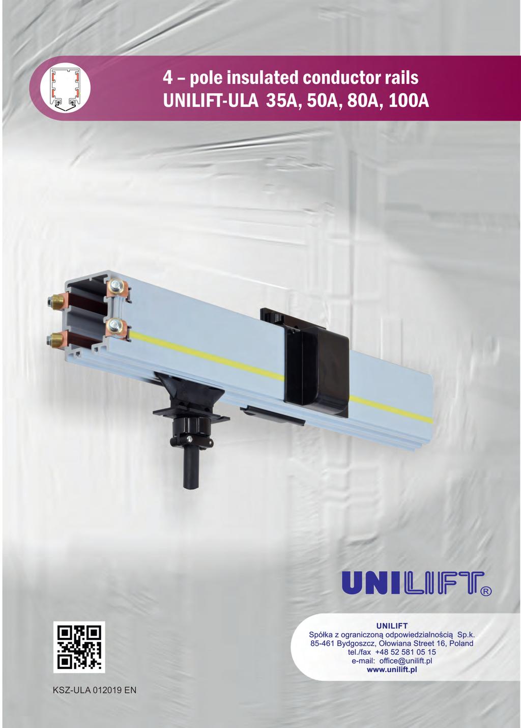
4 pole insulated conductor rails UNILIFT-ULA 35A, 50A, 80A, 100A
|
|
|
- Elizabeth Reed
- 5 years ago
- Views:
Transcription
1
2 2
3 Table of contents General information... 4 Elements of the conductor rail supply line... 4 Innovative connection method... 5 Technical properties... 6 Construction of the line section... 6 Line section... 6 Covering flange... 7 End cap... 7 Sliding hanger... 7 Fixing hanger... 7 Support arm with Ø11 mm... 8 Girder clip... 9 End feed... 9 End feed... 9 Expansion elements Curved sections Ventilation elements Current collectors 25A and 40A with connecting cable Double current collectors 2x40A with connecting cable Current collectors 25A and 40A for curved tracks with connecting cable Single towing arms Double towing arm Sealing strip Bolted joint ZS-ULA Carbon brushes for current collectors Symbols description Layout of the conductor rail line 35A, 50A with end feed Layout of the conductor rail line80a, 100A with end feed Layout of the conductor rail line 35A, 50A line feed Layout of the conductor rail line 80A, 100A line feedi Inquiry form


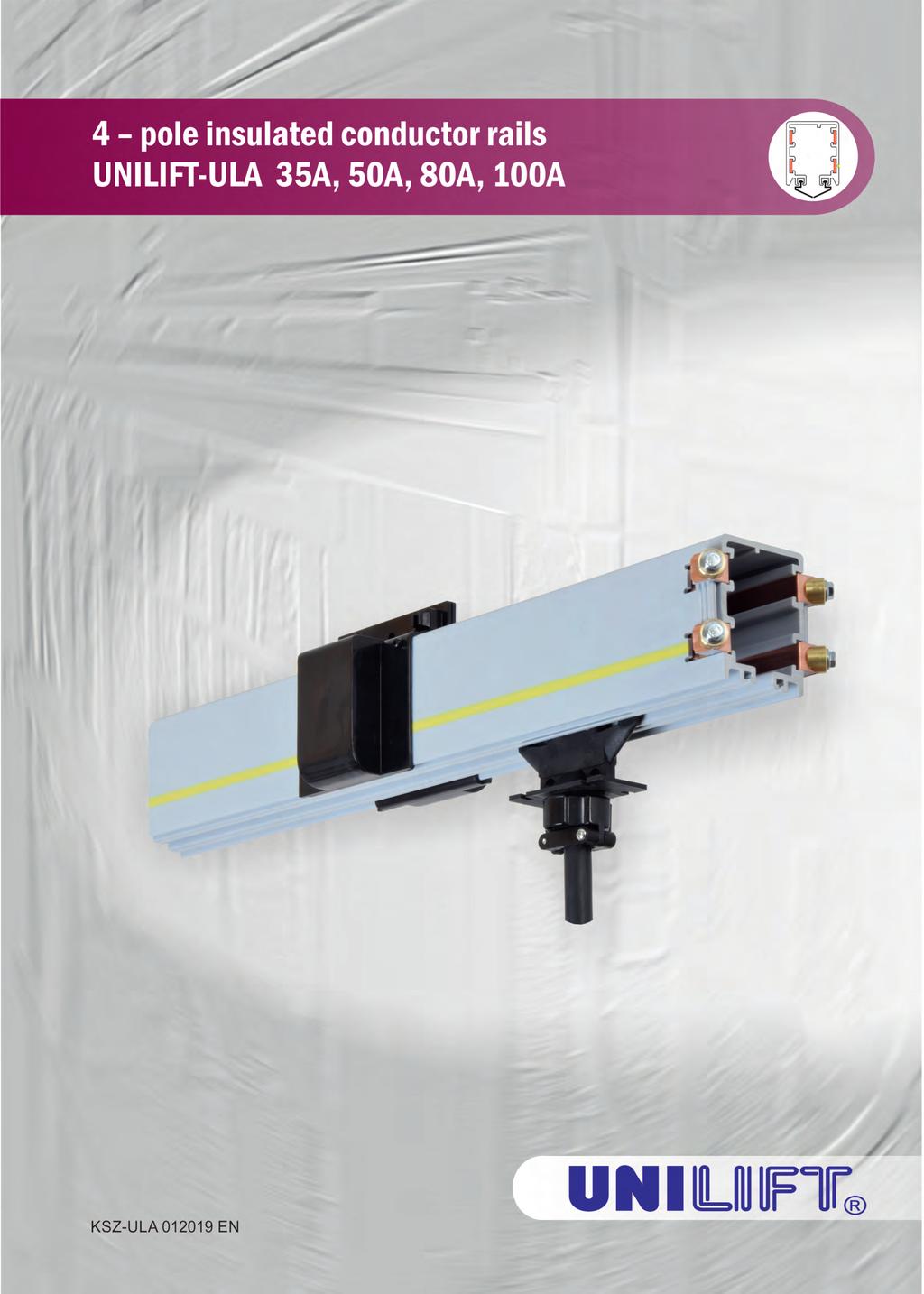
4 General information Conductor rails UNILIFT-ULA are designed for powering mobile receivers, mostly lifting devices like cranes and hoists. However, they can be applied for many other types of machines. Conductor rails UNILIFT-ULA are made in 4-pole version for nominal currents 35, 50, 80 and 100A with already mounted copper stripes. They are equipped with innovative bolted joint system (UNILIFT patent pending), providing fast, easy and certain connection. The construction of UNILIFT-ULA takes into account the difference between thermal extensibility of copper wires and PVC housing. Conductor rails UNILIFT-ULA ensure safety and reliable exploitation. Before installing the conductor rail line, be sure to read the installation guide available on UNILIFT website Elements of the conductor rail supply line Line section Covering flange End feed Current collector with connecting cable Sliding hanger Fixing hanger Towing arm Support arm with girder clips End cap
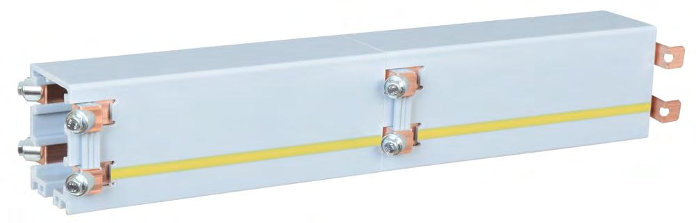
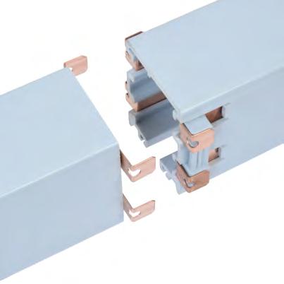
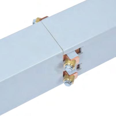
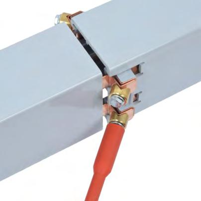
5 2. 1. Innovative connection method 3. 5

6 Construction of the line section Technical properties Electrical properties A Maximum phase-to-phase voltage 600 V Internal protection rating IP23 Dielectric strength kv/mm Volume resistivity 5 x 10¹⁵ Ω/cm Surface resistivity 1013 Ω Partial discharge strength L3 L2 73 Maximum nominal current L1 CTI 600-2,7 13 Combustibility properties Flame retardant, self extinguished DIN class B1 Mechanical properties Flexural strength 75 N/mm2 ±10% Tensile strength 40 N/mm2 ±10% Sealing strip (on request) Chemical properties Petrol Mineral oil Resistance to chemical compounds o (up to 45 C) L1 L2 L3 - Current phases Sulphuric acid 50% - Protective wire PE Caustic soda 50% (marked by yellow-green stripes on housing) Concentrated hydrochloric acid Other properties -40 to +75oC Ambient temperature ,22 1,87 1,25 0, [kg/m] 2,09 2,16 2,30 2,45 Length 4 [m] ULA ULA ULA ULA Length 3 [m] ULA ULA ULA ULA Length 2 [m] ULA ULA ULA ULA Length 1 [m] ULA ULA ULA ULA Other length [m] (or request) ULA ULA ULA ULA Nominal current Is [A] 2 Wire cross section s [mm ] o Impedance Z (To=35 C, f= 50 Hz) Number of poles 6 Line section


7 Covering flange Can be applied on curved tracks. Self-locking and easy to assembly. ULA ,16 ULA ,25 End cap Sliding hanger M10x ULA ,21 Fixing hanger M10x ULA ,17 7
![Support arm with Ø11 mm hole Ć11 Material: galvanized steel 30 Length [mm] ULA-00380 380 ULA-00500 500 ULA-00600 600 Cross section [mm x mm] 0,37 30 x 15 0,49 0,58 Support arm with girder clips fixed](/docs-images/88/115053944/images/8-0.jpg "to the upper shelf of the I-beam. L Girder clip LK-C11-40 30 B/2 Hole Ć11 (Place of fixation sliding hander ULA-00040 or fixing hanger ULA-00041) max. 20 max. 50 min.")
8 Support arm with Ø11 mm hole Ć11 Material: galvanized steel 30 Length [mm] ULA ULA ULA Cross section [mm x mm] 0,37 30 x 15 0,49 0,58 Support arm with girder clips fixed to the upper shelf of the I-beam. L Girder clip LK-C B/2 Hole Ć11 (Place of fixation sliding hander ULA or fixing hanger ULA-00041) max. 20 max. 50 min. 10 C-profile support arm 30x15x2 M8x40 A Support arm with girder clips fixed to the lower shelf of the I-beam. B/2 min. 10 A M8x40 Girder clip LK-C C-profile support arm 30x15x2 Hole Ć11 (Place of fixation sliding hander ULA or fixing hanger ULA-00041) L If other mounting solutions are required please contact Support arm length: 8 L=A+ B +k 2 mm L support arm length [mm] A distance from I-beam axis to bracket axis [mm] B I-beam footing width [mm] k length addition coefficient [mm Coefficient k [mm] For girder clip 70 LK-C11-40 Support arm length calculation using girder clips


 100 110 130 A Metric gland Dimension A")
![[mm] ULA-31025 M25 ~132 0,27 ULA-31032 M32 ~135 0,28 Line feed 128 150](/docs-images/88/115053944/images/9-4.jpg "To connect the power supply to (See the Installation Guide) Metric")
9 Girder clip 25x30 Material: galvanized steel ~ M8x40 Girder clips LK-C11-40 are designed to mount on construction elements which thickness is up to 20 mm To settle the support arm it is need to use 2 girder clips. Type ULA LK-C ,14 End feed To connect the power supply to the conductor rail line, apply the flexible cables finished with eyebolt connectors. (See the Installation Guide) A Metric gland Dimension A [mm] ULA M25 ~132 0,27 ULA M32 ~135 0,28 Line feed To connect the power supply to the conductor rail line, apply the flexible cables finished with eyebolt connectors. (See the Installation Guide) Metric gland ULA M25 0,25 ULA M32 0,26 9

10 Expansion elements Nominal current 35 A 5,42 50 A 5,67 ULA A 5,89 ULA A 6,22 Number of poles ULA ULA The expansion element is applied for compensate the difference in expansion between the conductor rail line and a support structure. In every single line with expansion element, a double current collectors should be used. That will guarantee the conduction continuity and a proper contact of carbon brushes in the expansion element er hang LN LZAS LBK LK LN - adjustable length of the expansion element - max. length of the supply line without the expansion element - length of the supply line without the expansion element - length of the zone with one expansion element Conductor rail supply line without the expansion element LBK Max. length of the supply lines Temperature difference ΔT [oc] The supply line without the expansion element LBK [m] The zone with one expansion element LK [m] LZAS = 2 LBK The zone with one expansion element LN LK 10 ng Slidi
11 The adjusting of the expansion element - example The length of the expansion element can be appointed in a two ways: 1 - according a simple calculation 2 - using a graph o Data: Min. ambient temperature : Tmin = -10 C o Max. ambient temperature: Tmax = +35 C o Ambient temperature during assembly : TM = +10 C Example 1 o T = Tmax - Tmin = 45 C o T1 = TM - Tmin = 25 C T1 25 = LN1 = = 2056 mm 45 T o LN1- adjustable length of the expansion element for ambient temperature during assembly TM = +25 C Example 2 o C 50 Ambient temperature mm LN Adjustable length of the expansion element LN The expansion element must be mounted in the centre between two fixing hangers. Double current collectors should be used. The outline of the conductor rail supply line with expansion element 2-2,1m LK L Description on the page 17 11
 max. R without limits Curved single section length: max. 3200 mm The curve track can be made up of many sections.")
12 Curved sections General informations: Curved section are made in horizontal position. Curved section in vertical position (or mixed) on request Curve radius: min. R = 800 mm ( smaller R on request) max. R without limits Curved single section length: max mm The curve track can be made up of many sections. The spacing between hangers for a curved section: The distance between the adjacent fixing hangers should not exceed 800 mm PE inside PE PE outside PE outside PE PE PE PE inside R-28 R R+28 R-28 R R+28 R α R PE inside α PE wire placement 12 Nominal current 35 A 50 A 80 A 100 A PE outside ULA ULA ULA ULA PE inside ULA ULA ULA ULA PE outside


13 The outline of the conductor rail supply line with curved sections and expansion element Conductor rail supply line with straight and curved sections The track of the powered device L ł 20 m * * Note: In case of straight supply line finished with curves from the both ends, the expansion element should be added according the rules showed on the pages 8-9. The expansion element should be mounted on the straight supply line when the distance between the curved sections endings is more than 20 m. The example of the closed loop curved conductor rail supply line The ordering of the curved sections The input data, necessary to make a proper curved section: catalog No., curve radius R mm, inner angle α or arc length mm, the outline of the complete supply line. 13
14 Ventilation elements 128 The ventilation element is installed in the same way as the standard sections of the conductor rail line, taking care that the cover of the ventilation zone is placed at a distance of 300 to 500 mm from the warm zone. A* L * A - precise the dimension in the order Nominal current ULA A ULA A ULA A ULA A L [m] A* [m] 4 The way of assembly The ventilation element is installed in the same way as the standard sections of the conductor rail line, taking care that the cover of the ventilation zone is placed at a distance of 300 to 500 mm from the warm zone. The outline of the conductor rail supply line with ventilation elements mm Ventilation element Warm zone 14 Cold zone


15 Current collectors 25A and 40A with connecting cable Current collector type ULA with connecting cable H07RN-F 4G2,5 mm2-0,8 m length Current collector type ULA with connecting cable H07RN-F 4G4 mm2-0,8 m length Number of poles ULA Current collector s speed: 120 m/min Nominal current 25A 0,65 40A 0,70 4 ULA Double current collector 2x40A with connecting cable Current collector type ULA with double connecting cable H07RN-F 4G4 mm2-0,8 m length Current collector s speed: 120 m/min Number of poles Nominal current ULA A 1,50 Current collectors 25A and 40A for curved tracks with connecting cable Current collector type ULA with connecting cable H07RN-F 4G2,5 mm2-0,8 m length Current collector type ULA with connecting cable H07RN-F 4G4 mm2-0,8 m length Number of poles ULA Nominal current 25A 0,50 40A 0,60 4 Current collector s speed: 80 m/min ULA Current collectors are adapted to use on curve tracks. Curve radius R > 800 mm 15

 mm Double towing arm is designed for double current collectors ULA-111804.")
16 Single towing arms 60 Material: galvanized steel 42 9 Square profile 40x M8 Example of mounting on square profile 40x40 mm ULA ULA ULA ,53 ULA ,55 bean shape hole 9x15 Ć Example of mounting on square profile 40x40 mm Double towing arm galvanized steel 185 Materiał: Square profile 40x40 (50x50) ULA Example of mounting on square profile 40x40 (50x50) mm Double towing arm is designed for double current collectors ULA It's adapted to mounting on a square profile 40x40 (50x50). 16

![[kg/m] ULA-00090 0,06 Bolted joint](/docs-images/88/115053944/images/17-1.jpg "ZS-ULA Material: body pressure sleeve")


17 Sealing strip Sealing strip should be used in a dusty environment. [kg/m] ULA ,06 Bolted joint ZS-ULA Material: body pressure sleeve bolts, nuts - polypropylene - brass - galvanized steel Type ULA ZS-ULA 0,03 Carbon brushes for current collectors ULA For current collectors ULA ULA-10254, ULA-10404, ULA ,04 ULA ULA-20254, ULA ,04 ULA
18 Symbols description Line section Covering flange (connection point) Fixing hange Sliding hanger End cap Line feed End feed Expansion element Ventilation element The diagrams show an example of the placement of individual components of the conductor rail line. The quantity and location of the supply components depends on the calculated permissible voltage drop and operating conditions. 18
19 Layout of the conductor rail line 35A, 50A with end feed L n x n x 0,35m 0,35m 1,65m ** ** additional sliding hanger 0,35m L/2 L/2 Layout of the conductor rail line 80A, 100A with end feed L n x 1,33m 1,33m 1,33m n x 1,33m 1,33m 1,33m 1,33m 1,33m 1,33m 1,33m 1,33m 0,35m 0,99m 0,35m ** ** additional sliding hanger 0,35m L/2 L/2 19
20 Layout of the conductor rail line 35A, 50A with line feed L n x n x 0,35m 0,35m 1,65m ** 0,35m ** additional sliding hanger L/2 L/2 Layout of the conductor rail line 80A, 100A with line feed L n x 1,33m 1,33m 1,33m n x 1,33m 1,33m 1,33m 1,33m 1,33m 1,33m 1,33m 1,33m 0,35m 0,99m 0,35m ** ** additional sliding hanger 0,35m L/2 L/2 20

21 Inquiry form List of items: 8 1. Line section 2. Covering flange 3. End feed 4. Current collector with connecting cable 5. Sliding hanger 6. Fixing hanger 7. Towing arm 8. Support arm with girder clips 9. End cap Conductor rail power supply length: Power supply parameters: U= V Frequency: f= Hz Number of poles: L= m AC Voltage: 2 DC phases + PE Device characteristics Motor data Duty cycle (% ED) cos φn Nominal current IN [A] Power consumption [kw] Crane/device 3 Duty cycle (% ED) cos φn Nominal current IN [A] Power consumption [kw] Crane/device 2 Duty cycle (% ED) cos φn Nominal current IN [A] Device name Power consumption [kw] Crane/device 1 Main lift drive Auxiliary lift drive Trolley drive Other Bridge drive 21
22 Device localisation: indoor outdoor mixed Environment: normal high humidity dust chemically aggressive (description) Working temperature range: o o Acceptable voltage drop: at start (default: 5 %) C min. C max. in continous (default: 2%) Current collector speed: m/min Location of power points: at the end of the line in the middle of the line other (description) Support arm fastening by girder clips to the I-beam: yes Fastening on higher shelf: B/2 30 B/2 A min. 10 Hole Ć11 A mm Fastening on lower: L min. 10 Support arm length: L = 30 Examples of mounting Hole Ć11 L Contact data: Company: Address: Contact person: Office: Phone number: Date: 22
23 23
24
4 pole insulated conductor rails ULA 35A, 50A, 80A, 100A
 Table of contents General information... 3 Elements of the conductor rail supply line... 3 Innovative connection method... 3 Technical properties... Construction of the line section... Line section...
4 pole insulated conductor rails ULA 35A, 50A, 80A, 100A
 Table of contents General information... 3 Elements of the conductor rail supply line... 3 Innovative connection method... 3 Technical properties... Construction of the line section... Line section...
Energy Supply Systems
 Energy Supply Systems MULTIPOLE CONDUCTOR RAIL 831 10-125 amps KAT0831-0001b-E 13 pole multipole conductor rail in 33 package distribution centres of the postal service (Post AG) 9 pole multipole conductor
Multipole Conductor Rail MultiLine Program 0831
 Multipole Conductor Rail MultiLine Program 0831 Contents Description / Technical Data Description....2 Technical Data....3 Conductor Rails Rails complete with pre-mounted Connector...4 Power Feeds....5
Energy Supply Systems
 Energy Supply Systems SINGLE POLE INSULATED CONDUCTOR RAIL 815 100 amps KAT0815-0001b-E Conductor rail system in a high bay storage Slip ring with conductor rail system in a stretch-foil packing machine
GENERAL INDEX TR60. 6 YELLOW LINE Continuous Conductors. Max 5 Poles. 8 BLUE LINE Pre-Mounted Conductors TR85H5P. YELLOW LINE Continuous Conductors
 2 Automation - Lift - Handling System GENERAL INDEX 2 DESCRIPTION 3 BUSBAR LINE VERSIONS LINE TYPE / AMPERAGE COVERAGE 5 TR60 40 A 50 A 60 A 70 A 100 A 140 A 160 A 200 A 320 A 6 YELLOW LINE Continuous
1 Product Description System Layout Safety Instructions Intended Use Installation... 3
 Order Number 0812xx- Contents 1 Product Description... 2 2 System Layout... 2 3 Safety Instructions... 3 4 Intended Use... 3 5 Installation... 3 5.1 Hanger Clamp... 3 5.2 Cutting of Conductor Rail... 4
Multipole Conductor Rail MultiLine Program 0831
 Multipole Conductor Rail MultiLine Program 0831 ProShell - the modular carrier profile as a system supplement for program 0812 and 0831 ProShell catalog KAT0800-0003-E available for download at www.conductix.com
1 Product Description System Layout Safety Instructions Intended Use Installation... 3
 Part Number 0812xx- Contents 1 Product Description... 2 2 System Layout... 2 3 Safety Instructions... 3 4 Intended Use... 3 5 Installation... 3 5.1 Hanger Clamp... 3 5.2 Cutting of Conductor Rail... 4
Insulated Conductor Rail SinglePowerLine Program 0813
 Insulated Conductor Rail SinglePowerLine Program 0813 Table of Contents System Description 5 Technical Data 6 General Instructions 7 System Structure 8 Components and their use... 8 Insulated Conductor
1 Product Description Check of the supplied Parts Notes Intended Use Current Collector... 3
 Order number 0813xx-... Contents 1 Product Description... 2 2 Check of the supplied Parts... 2 3 Notes... 2 4 Intended Use... 2 5 Current Collector... 3 6 Installation Sequence... 3 7 Pickup Guide... 7
4 Pole / 5 Pole Enclosed Conductor System
 4 / 5 Pole Conductor System 4 Pole / 5 Pole Enclosed Conductor System Enclosed Conductor system with IP23 Finger proof cellular profile. Available in intensities from 20 Amp 200 Amp Data sheet ref : 10
4-Ductor Insulated conductor bar
 Darwinstraat 10 4-Ductor AKAPP 4-Ductor current supply system compact, reliable and safe! AKAPP 4-Ductor is a compact, reliable and safe current supply system for cranes, hoists, monorail systems, conveyor
Insulated Conductor Rail SinglePowerLine Program 0812
 Insulated Conductor Rail SinglePowerLine Program 0812 2 Table of Contents System Description 5 Technical Data 6 General Instructions 7 System Structure 8 Components and their use... 8 Insulated Conductor
POWERAIL ENCLOSED CONDUCTOR SYSTEM VKS 10
 POWERAIL ENCLOSED CONDUCTOR SYSTEM VKS 10 POWERAIL ENCLOSED CONDUCTORS VKS 10 CONTENTS Page General 2, 3 Planning guide 4 Technical data, standard sections 6, 7 Curved sections 8 Jointing material 8 Hangers
A COMPLETE LINE OF INNOVATIVE PRODUCTS
 A COMPLETE LINE OF TOUTE UNE LIGNE D INNOVATIONS. INNOVATIVE PRODUCTS ELECTRIFICATION OF TRAVELLING MACHINES Manufacturers: performance and economy. MOBILIS Elite has the advantage of high performance
Bolted, snap-in and guarter turn type hangers are available. Standard support distance for U12 is 600mm, in curves 300mm.
 General Komay insulated conductors U12 are designed in accordance with today s international safety requirements. The shroud which envelopes the various conductors is an excellent insulator. Therefore
Technical data. DKK compact conductor lines engb IS eps
 Technical data DKK compact conductor lines 4146644.eps 10910 engb 0 540 44 714 IS 9 Contents 1 Technical information Straight sections 4 Curved sections 5 4 Powerfeeds 6 5 Ramp sections, expansion joints
Insulated Conductor Rail SinglePowerLine Program 0812
 Insulated Conductor Rail SinglePowerLine Program 0812 Table of Contents System Description 5 Technical Data 6 General Instructions 7 System Structure 8 Components and their use....8 Insulated Conductor
1 Product Description Check of the supplied Parts Notes Intended Use Current Collector... 3
 Part number 0813xx-... Contents 1 Product Description... 2 2 Check of the supplied Parts... 2 3 Notes... 2 4 Intended Use... 2 5 Current Collector... 3 6 Installation Sequence... 3 7 Pickup Guide... 6
COMPACT CONDUCTOR SYSTEMS VKS 10
 COMPACT CONDUCTOR SYSTEMS VKS 10 POWERAIL ENCLOSED CONDUCTORS VKS 10 CONTENTS Page General 2, 3 Planning guide 4 Application photos 5 Technical data, standard sections 6, 7 Curved sections and jointing
Conductor Bar Series 812
 Conductor Bar Series 812 Contents Page 1 Completeness of the delivered parts... 1 2 Hints... 2 3 Installation... 2 4 Maintenance... 6 5 Photos of relevant system parts... 8 In addition to other advantages,
Manual Monorail Track System
 www.wampfler.com Page 1/57 www.wampfler.com Page 2/57 1 General...6 1.1 Use of standard elements...7 1.2 Determination of the permissible support centers...9 1.3 Questionnaire...11 1.4 Project notes...12
Heavy-Duty Conductor Rail CopperHead
 Heavy-Duty Conductor Rail CopperHead Table of Contents CopperHead Conductor Systems 4 Heavy-Duty Conductor Rails...4 Some Advantages of CopperHead Rail Systems...4 Product Pre-Selection...4 Technical
POWERAIL ENCLOSED CONDUCTOR SYSTEM VKS 10
 POWERAIL ENCLOSED CONDUCTOR SYSTEM VKS 10 POWERAIL ENCLOSED CONDUCTORS VKS 10 CONTENTS Page General 2, 3 Planning guide 4 Technical data, standard sections 6, 7 Curved sections 8 Jointing material 8 Hangers
POWER BAR SYSTEM ECONOMICAL ENCLOSED CONDUCTOR SYSTEM FOR MOBILE EQUIPMENT M O B I L E E L E C T R I F I C A T I O N
 A e r o B A R POWER BAR SYSTEM ECONOMICAL ENCLOSED CONDUCTOR SYSTEM FOR MOBILE EQUIPMENT M O B I L E E L E C T R I F I C A T I O N AeroBAR Enclosed Conductor Bar System AeroBAR provides many of the advantages
Conductor Bar Safe-Lec 2 Hevi-Bar II
 Conductor Bar Safe-Lec 2 Hevi-Bar II Contents Safe-Lec 2 and Hevi-Bar II Overview 3 Conductor Bar Summary Chart 4 Quick Quote Software 5 Quotations Data Sheet 6-7 Safe-Lec 2 8-33 Safe-Lec 2 System Components
Conductor Bar Safe-Lec 2 Hevi-Bar II
 Conductor Bar Safe-Lec 2 Hevi-Bar II Contents 2 Safe-Lec 2 and Hevi-Bar II Overview 3 Conductor Bar Summary Chart 4 Quick Quote Software 5 Quotations Data Sheet 6-7 Safe-Lec 2 8-33 Safe-Lec 2 System Components
Energy Supply Systems
 Energy Supply Systems -RAIL PROGRAM 270 KAT0270-0001b-E -Rails and Accessories for Curved Tracks -Rail 30 x 30 90 o -Curve Track Coupler l Static values 027200-6 6000 l x = 2.95cm 4 027200-4 4000 W x =
Conductor Bar Safe-Lec 2 Hevi-Bar II
 Conductor Bar Safe-Lec 2 Hevi-Bar II Contents Safe-Lec 2 and Hevi-Bar II Overview 3 Conductor Bar Summary Chart 4 Quick Quote Software 5 Quotations Data Sheet 6-7 Safe-Lec 2 8-33 Safe-Lec 2 System Components
Conductor Rail System for Shuttles MultiLine Program 0835
 MultiLine Program 0835 Table of Contents General Information 5 System Advantages 5 Main Features at a Glance 6 Technical Data 7 Conductor Rail 8 End Segment (End Power Feed) 8 Rail Connector 9 Standard
Electrobar Elite. Instruction Manual. Conductor Bar System. ELITE-03A October 2011 Part Number: R3 Copyright 2011 Electromotive Systems
 Electrobar Elite Conductor Bar System Instruction Manual ELITE-03A October 2011 Part Number: 005-1054-R3 Copyright 2011 Electromotive Systems 2011 MAGNETEK All rights reserved. This notice applies to
POWERAIL CONDUCTOR SYSTEMS MKLD MKLF MKLS
 POWERAIL CONDUCTOR SYSTEMS 19 12 POWERAIL INDEX Page Powerail versions 3 Basic description 3 Technical data 3 Powerail types, cat. nos. and weights 4 Engineering data and configurations 5 Standard sections,
Conductor Rail System for Shuttles MultiLine Program 0835
 MultiLine Program 0835 Table of Contents General Information 5 System Advantages 5 Main Features at a Glance 6 Technical Data 7 Conductor Rail 8 End Segment (End Power Feed) 8 Rail Connector 9 Standard
Series T is Ideal for:
 Series T SAF-T-BAR Series T is Ideal for: Light Rail Systems Automated Storage and Retrieval Systems Conveyors Indoor, Dry Locations Small cranes, monorails, hoists Moving cameras and instruments Other
Technical data Demag DC-Com 1 to DC-Com 10 chain hoist
 Technical data Demag DC-Com 1 to DC-Com 10 chain hoist 42647546.jpg 090506 EN 203 571 44 714 IS 817 Design overview Single-fall design 1 2 4 3 6 5 7 8 9 14 16 15 13 1 Electrical equipment cover 2 Brake
FABA. Standard Components. Conductor Bar System. publication #FABASC-04 1/1/04 Part Number: Copyright 2003 Electromotive Systems
 FABA Conductor Bar System Standard Components publication #FABASC-04 1/1/04 Part Number: 000-2201 Copyright 2003 Electromotive Systems Table of Contents Section IS 100 A - Introduction General Information
UNCHAINED ENERGY ELECTRIFICATION OF TRAVELLING MACHINES
 UNCHAINED ENERGY ELECTRIFICATION OF TRAVELLING MACHINES MOBILIS MOVIT : ELECTRIFICATION LINE WITH SINGLE POLE CONDUCTOR RAILS 315A - 450A - 630A HIGHER PERFORMANCE Designed in aluminium with a stainless
UNCHAINED ENERGY ELECTRIFICATION OF TRAVELLING MACHINES
 UNCHAINED ENERGY ELECTRIFICATION OF TRAVELLING MACHINES As a leading specialist in electrical power supply, FELS is broadening its MOBILIS range with a highly innovative line of singleconductor rails boasting
MOTIV- 8 FLEXIBLE CABLE SYSTEMS. www. James Crane.com.au PH:
 MOTIV- 8 FLEXIBLE SYSTEMS www. James Crane.com.au PH: 1300 780 420 Email: Robert@jamescrane.com.au CONTENTS System Selection Enquiry Sheet Carrying Capacity kg Recommended Maximum Speed (m/min) Wire Rope
ALINOX INSULATED CONDUCTOR RAIL FOR ELECTRICAL FEEDING OF CRANES
 ALINOX INSULATED CONDUCTOR RAIL FOR ELECTRICAL FEEDING OF CRANES 2 ALINOX INSULATED CONDUCTOR RAIL Features, advantages and benefit The insulated conductor rail system ALINOX is the most suitable solution
1. SPECIFICATION. Altitude of motor installation. Information: Resistance and temperature specifications of the PTC thermistor / posistor/.
 1. SPECIFICATION 5 GENERAL INFORMATION Motors with parameters according to the data sheet comply with the requirements of the IEC 60034-1 standard, and IEC 60034-30 class efficiency IE2 Motor versions:
Insulated Conductor Rail SingleFlexLine Program 0811
 Insulated Conductor Rail SingleFlexLine Program 0811 Contents System Description 5 Technical Data 6 System Components and Standards 7 Components and their use...7 Project Planning 9 Technical notes and
Cable Festoon Systems - For Moving Machinery
 Cable Festoon Systems - For Moving Machinery CONDUCTIX offers a comprehensive range of Cable Festoon Systems to power moving machinery. Our festoon systems are ideal for supporting, protecting, and managing
POWERAIL ENCLOSED CONDUCTOR SYSTEM KBH
 POWERAIL ENCLOSED CONDUCTOR SYSTEM KBH POWERAIL KBH Contents Page Contents Page System photo 2 Removing sections, Conductor dead sections 14 General 2, 3 Anti-condensation sections, Expansion sections
Electromotive Systems ELECTROBAR ELITE Conductor Bar System
 Electromotive Systems ELECTROBAR ELITE Conductor Bar System ELECTROMOTIVE SYSTEMS ELECTROBAR ELITE ENCLOSED CONDUCTOR BAR SYSTEMS Magnetek s Electromotive Systems division proudly offers ELECTROBAR Elite,
VAHLE MOTOR POWERED CABLE REELS
 VAHLE MOTOR POWERED CABLE REELS INDEX Page Introduction 2, 3 Cable selection 4 Typical applications 5 Questionnaire 6, 7 Model explanation 8 36 Reel selection charts monospiral wrap, horizontal payout
"...Let things run smoother - HELM technologie"
 Group 14 a -aluminium- ALUMINIUM LIGHT CRANE SYSTEM "...Let things run smoother - HELM technologie" - Individual solution for every workplace - Extreme load-bearing capacity - Extensive accessories upon
Fuse switch disconnectors
 SWITCHGEAR RBK Fuse switch disconnectors intended for distribution of electricity and protection of electrical equipment against short-circuits and overloads, with industrial fuse links ENERGY SAFELY SWITCHED
GmbH Lufttechnik Dresden USER INFORMATION ROOF FANS SERIES VRV. vertical outlet. Issue 07/02
 GmbH Lufttechnik Dresden USER INFORMATION ROOF FANS SERIES VRV vertical outlet Issue 07/02 Roof fans made of plastic materials Series VRV with vertical outlet Usable in ventilation engineering of all branches
Cable Trolleys for C-Rails Program
 Cable Trolleys for C-Rails Program 02 0 0260 Contents C-Rail and Accessories Program 02 C-Rail x... 4 Track Coupler... 4 End Stops... 4 Track Support Brackets... 4 Support Arm and Girder Clip... Brackets...
OFFSHORE WIND FEASIBILITY STUDY APPENDICES Appendix C.2 Subsea Cable Data Sheets
 OFFSHORE WIND FEASIBILITY STUDY APPENDICES 10-7 10.3.2 Appendix C.2 Subsea Cable Data Sheets Design data for TFVA 36 kv 3x1x240 mm 2 KQ Metallic Laying up Inner sheath Bedding Armor Diameter of conductor
Cable Festoon Systems - For Moving Machinery
 Cable Festoon Systems - For Moving Machinery CONDUCTIX offers a comprehensive range of Cable Festoon Systems to power moving machinery. Our festoon systems are ideal for supporting, protecting, and managing
Miniature Intermediate Power Relay HY
 Miniature Intermediate Power Relay HY A switching capabilities (C, C).kV dielectric strength (between coil and contacts) Various terminals, test button available Different sockets available to pole configurations
Pro-Ductor Insulated flat conductor bar for 4, 7 or 10 conductors
 Darwinstraat 10 NL 6718 XR Ede The Netherlands Flexible with energy! Phone +31 (0)342 403900 Fax +31 (0)342 403912 email info@akapp.com URL www.akapp.com Pro-Ductor Insulated flat conductor bar for 4,
Energy Supply Systems C-RAIL PROGRAM. KAT a-USA
 Energy Supply Systems C-RAIL PROGRAM 230 KAT0230-0001a-USA C-Rails and Accessories C-Rails Catalog No. Length l Thickness s [mm] [mm] 023200-6M 6000 023200-4M 4000 023201-6M 6000 023201-4M 4000 2 1.5 6,,
Technical data Demag chain hoist DC-Pro 1, DC-Pro 2, DC-Pro 5, DC-Pro 10, DC-Pro 20 Demag Manulift chain hoist DCM-Pro 1, DCM-Pro 2, DCM-Pro 5
 Technical data Demag chain hoist 1,,, 1, Demag Manulift chain hoist DM-Pro 1, DM-Pro, DM-Pro 46474.eps 1 EN 3 44 714 IS 817 Design overview Single-fall design 1 4 3 6 7 8 9 14 16 1 13 1 Electrical equipment
C-Rail Festoon track systems
 C-Rail Festoon track systems & Hose carrying systems Application C-Rail festoon track systems are the ideal solution for carrying cables supplying power to many types of moving machinery using either flat
QuickBridge TM. Modern Overhead Crane Bridge Electrification
 QuickBridge TM Modern Overhead Crane Bridge Electrification Features and Benefits QuickBridge TM is a new concept in bridge electrification to give your overhead cranes a clean, contemporary look. QuickBridge
FISCHER FREEDOM TM SERIES
 K CHAPTER FISCHER TM SERIES EASY MATING EASY CLEANING EASY INTEGRATION KEY FEATURES No key code: 360 mating freedom & optimized cable management Membrane-sealed contacts (patent pending) Low profile IP68
Product Information ECN 425 EQN 437. Absolute Rotary Encoders with Hollow Shaft and Expanding Ring Coupling for Safety-Related Applications
 Product Information ECN 425 EQN 437 Absolute Rotary Encoders with Hollow Shaft and Expanding Ring Coupling for Safety-Related Applications 4/2014 ECN 425, EQN 437 Rotary encoders for absolute position
PROBABLY THE BEST FLEXIBLE BAR IN THE WORLD
 PROBABLY THE BEST FLEXIBLE BAR IN THE WORLD 2COFLEX COFLEX, THE 4.0 FLEXIBLE BAR From a Teknomega new and advanced manufacturing plant, COFLEX, the only bi-color flexible bar (patented), distinguishes
Conductor: plain wire, fine stranding as per VDE 0295 class 6 from 50 mm² fine stranding according to VDE 0295 class 5
 Semoflex DRUM Description Application In dry and damp rooms, explosive security areas and also outdoors for heavy-duty units such as hoisting gears, transportation systems, motorized cable reels, rail
Flexible energy and data transmission
 Flexible energy and data transmission Cable trolleys PRB0200-0001c-E Programme 210 Steel rope Load capacity: up to 20 kg Rope programme 210 215 Rope diameter [mm] 6-8 8-12 Max. load capacity/trolley [kg]
Electronic Circuit Breaker ESS20-0..
 Electronic Circuit Breaker ES-0.. Description Electronic circuit breaker type ES-0.. is designed to ensure selective disconnection of individual loads in systems which are powered by a DC 4 V switch-mode
MOTIV-8 FLEXIBLE CABLE SYSTEMS
 MOTIV-8 FLEXIBLE CABLE SYSTEMS www.conductix.com.au CONDUCTIX FLEXIBLE CABLE SYSTEMS Designed and manufactured in Australia. Proven in applications throughout the world for over 25 years. Full range of
GF Piping Systems. Stress Less. Pipe and Valve Support System Finally, just for plastic pipe. Patents issued and pending
 GF Piping Systems Stress Less Pipe and Valve Support System Finally, just for plastic pipe Patents issued and pending Problem Improper piping system support can result in premature Traditional piping supports
SAFELEC. INSULATED CONDUCTOR BARS 60 up to 800 Amp
 INSULATED CONDUCTOR BARS 60 up to 800 Amp Finger safe up to IP2 60 to 800 Amp conductors in Standard or Medium Heat Cover shaped to shed water and dust Horizontal conductors with contact from underside
MACHT STROM MOBIL. Enclosed conductor system KBH SYSTEMS IN MOTION
 MACHT STROM MOBIL Enclosed conductor system KBH SYSTEMS IN MOTION 4b/en 2013 2 Enclosed conductor system KBH Content... Page Description of the Conductor system... 3 Technical description... 4 Technical
Electric Chain Hoists. CLF & CLW Series. The New CLF Series: Reliable, safe, convenient, efficient and compact size
 Industrial Cranes Customized Cranes Light Crane Systems Crane Components Electric Wire Rope Hoists Electric Chain Hoists Spare Parts Electric Chain Hoists CLF & CLW Series The New CLF Series: Reliable,
ACI Hoist & Crane. Festoon System. 689 S.W. 7th Terrace Dania, FL (954) Fax (954) Toll Free A-HOIST ( )
 Fax (954) Toll Free A-HOIST ( )") ACI Hoist & Crane Festoon System 689 S.W. 7th Terrace Dania, FL 33004 (954) 921-1171 Fax (954) 921-7117 Toll Free 1-888-4-A-HOIST (1-888-424-6478) www.acihoist.com 2 Standard Duty C-Track Index 1. General
ACI Hoist & Crane Festoon System 689 S.W. 7th Terrace Dania, FL 33004 (954) 921-1171 Fax (954) 921-7117 Toll Free 1-888-4-A-HOIST (1-888-424-6478) www.acihoist.com 2 Standard Duty C-Track Index 1. General
up to 63 A (1 module per pole)
") 87045 LIMOGES Cedex Telephone: +33 5 55 06 87 87 FAX: +33 5 55 06 88 88 Direct current MCB DX 3 16kA, up to 63 A (1 module per pole) CONTENTS PAGE 1. Description - Use... 1 2. Range... 1 3. Overall dimensions...
87045 LIMOGES Cedex Telephone: +33 5 55 06 87 87 FAX: +33 5 55 06 88 88 Direct current MCB DX 3 16kA, up to 63 A (1 module per pole) CONTENTS PAGE 1. Description - Use... 1 2. Range... 1 3. Overall dimensions...
CABLE CARRIERS for -Track
 CABLE CARRIERS for -Track VAHLE FESTOON SYSTEMS Contents General Information 3 Questionnaire 4 S 1 Track & Accessories 5 9 LS 1 Cable carriers & Accessories Polyamid type 10 S 1 Cable carriers & Accessories
ENYSTAR Load Centers up to 250 A
 PASSION FOR POWER. up to 250 A according to IEC 61439-3 for commercial and industrial buildings Download at www.hensel-electric.en made in GERMANY since 1931 up to 250 A according to IEC 61439-3 for commercial
Pro-Ductor Insulated flat conductor bar for 4, 7 or 10 conductors
 Wabtec Netherlands B.V. Darwinstraat 10 NL 6718 XR Ede The Netherlands Flexible with energy! Phone +31 (0)342 403900 Fax +31 (0)342 403912 Email info@akapp.com URL www.akapp.com Pro-Ductor Insulated flat
K CHAPTER FREEDOM TM SERIES EASY MATING EASY CLEANING EASY INTEGRATION FISCHER KEY FEATURES
 K CHAPTER FISCHER TM SERIES EASY MATING EASY CLEANING EASY INTEGRATION KEY FEATURES No key code: 360 mating freedom & optimized cable management Membrane-sealed contacts (patent pending) Low profile IP68
JUMO MIDAS Pressure transmitter
 Phone: +44 19 635533 Fax: +44 19 6356 Data Sheet 401001 Page 1/5 JUMO MIDAS Pressure transmitter Brief description Pressure transmitters are used for measuring the relative (gauge) pressure in liquids
Compact Conductor System VKS10 SYSTEMS IN MOTION
 Compact Conductor System VKS10 SYSTEMS IN MOTION 3a/en 2016 Content General...3 System diagram...5 Sections...6 Pole configuration...7 Curved sections...8 Fixpoint hanger...9 End cap...9 Sliding hanger...9
SUPPLY SYSTEMS OF MOBILE RECEIVERS
 SUPPLY SYSTEMS OF MOBILE RECEIVERS About the Company UNILIFT Ltd based in Bydgoszcz was established in 1985 with the aim of performing comprehensive and professional technical service for lifting equipment.
Data sheet: Wilo-CronoLine-IL 125/210-5,5/4
 Data sheet: Wilo-CronoLine-IL 15/1-5,5/ Pump curves -pole, 5 Hz H[m] 18 16 1 1 1 8 6 P [kw] 8 1 16 6 Qmin IL 15/-5,5/ IL 15/1-5,5/ IL 15/19-/ Wilo-CronoLine-IL 15/ - Wilo-CronoLine-IL 15/19 IL 15/-7,5/
CONTENTS 1 GENERAL 2 STANDARDS. 3 TECHNICAL FEATURES 3.1 Basic Technical Data 3.2 Standard Accessories 3.3 Tolerances
 CONTENTS 1 GENERAL 2 STANDARDS 3 TECHNICAL FEATURES 3.1 Basic Technical Data 3.2 Standard Accessories 3.3 Tolerances 4 MOTOR DESIGN 4.1 Stator Casing 4.2 Stator Core with Winding 4.3 Stator Winding 4.4
Data sheet: Wilo-VeroLine-IPL 100/ /4
 Data sheet: Wilo-VeroLine-IPL 1/145-1.5/4 Pump curves 4-pole, 5 Hz H[m] Qmin 1 8 Wilo-VeroLine-IPL 1/175 - Wilo-VeroLine-IPL 1/135 Approved fluids (other fluids on request) Heating water (in accordance
MULTIGO. EBARA Pumps Europe S.p.A. CENTRIFUGAL PUMPS. Page
 CONTENTS 1 Page - SPECIFICATIONS 200 PERFORMANCE RANGE and SELECTION CHART 201 TYPE KEY and CURVES SPECIFICATIONS 202 PERFORMANCE CURVES 40 203 PERFORMANCE CURVES 80 204 - CONSTRUCTIONS SECTIONAL VIEW
user's manual nx frequency converters brake resistors
 user's manual nx frequency converters brake resistors INDEX Document code: ud00971e Date edited: 1.10.010 1. GENERAL... 3 1.1 Requirement for braking... 3 1. Brake components... 3 1.3 Classes of use...
DryLin R Linear Plain Bearings, Fast and Quiet
 +90º 40º +250º 100º Linear Plain Bearings, Fast and Quiet linear plain bearings, made from solid polymers, are dimensionally equivalent to standard ball bearings. They are made entirely of wear resistant
Conductor Bar. 8 Bar Side Contact
 Conductor Bar 8 Bar Side Contact Contents Conductor Bar Summary Chart 3 Quick Quote Software 4 Comparison of 8 Bar and Safe-Lec 2 5 Quotations Data Sheet 6-7 Insul 8 8 Bar and Side Contact Overview 8 8
Data sheet: Wilo-CronoLine-IL 65/130-4/2
 Data sheet: Wilo-CronoLine-IL 65/13-4/2 Pump curves 2-pole, 5 Hz H[m] 32 28 24 I 2 I 16 12 8 4 2 4 6 8 1 5 1 15 2 25 3 Q[l/s] P 2 [kw] Ø 14 6 Ø 127 4L Ø 117 2 Ø 18 2 4 6 8 1 η p[%] Qmin IL 65/14-5,5/2
Data sheet: Wilo-CronoLine-IL 50/200-1,5/4
 Data sheet: Wilo-CronoLine-IL 5/2-1,5/4 Pump curves 4-pole, 5 Hz H[m] 18 16 14 12 1 8 6 4 2 1 2 3 4 5 4 8 12 Q[l/s] P 2 [kw] Ø 28 1,5 Ø 197 1,,5 1 2 3 4 5 η p[%] Qmin Wilo-CronoLine-IL 5/22 - Wilo-CronoLine-IL
Data sheet: Wilo-CronoLine-IL 50/120-2,2/2
 Data sheet: Wilo-CronoLine-IL 5/12-2,2/2 Pump curves 2-pole, 5 Hz H[m] 28 24 2 Qmin IL 5/14-3/2 IL 5/13-3/2 Wilo-CronoLine-IL 5/14 - Wilo-CronoLine-IL 5/11 IL 5/14-4/2 Approved fluids (other fluids on
Data sheet: Wilo-CronoLine-IL 80/145-1,1/4
 Data sheet: Wilo-CronoLine-IL 8/145-1,1/4 Pump curves 4-pole, 5 Hz H[m] 12 1 8 6 4 2 2 4 6 8 1 5 1 15 2 25 3 P 2 [kw] 2, 1,5 Ø 156 1, Ø 144,5 Ø 133 2 4 6 8 1 η p[%] Qmin IL 8/17-2,2/4 IL 8/16-1,5/4 IL
Data sheet: Wilo-VeroLine-IPL 65/ /2
 Data sheet: Wilo-VeroLine-IPL 65/145-5.5/2 Pump curves 2-pole, 5 Hz H[m] 3 25 15 5 Qmin IPL 65/155-5,5/2 Wilo-VeroLine-IPL 65/155 - Wilo-VeroLine-IPL 65/145 IPL 65/145-5,5/2 IPL65/155-7,5/2 5 3 4 5 6 7
guide trough systems aluminium SuperTrough steel guide trough support tray guidefast guidelite tubular trough snap-in trough
 guide trough systems aluminium SuperTrough steel guide trough support tray guidefast guidelite tubular trough snap-in trough 682 683 Guide troughs Aluminium Steel Guide troughs Further trough systems The
- CONSTRUCTIONS 300 SECTIONAL VIEW DRAWING 300 SECTIONAL VIEW TABLE 301 MECHANICAL SEAL 302 QUANTITY FOR MODEL 303 BEARINGS 303
 CONTENTS Page - SPECIFICATIONS 200 SELECTION CHART 201 TYPE KEY AND CURVE SPECIFICATION 202 PERFORMANCE CURVE 40/86 203 PERFORMANCE CURVE 40/106 204 PERFORMANCE CURVE 40/126 205 PERFORMANCE CURVE 40/156
ProEMS Insulated Conductor Rail for Electrified Monorail Systems Program 0815
 ProEMS Insulated Conductor Rail for Electrified Monorail Systems Program 0815 Supplementary Documents Installation instructions: MV0815-0007-EN Installation Instructions for Conductor Rail System 0815
DryLin R Linear Plain Bearings, Fast and Quiet
 +90º 40º +250º 100º Linear Plain Bearings, Fast and Quiet linear plain bearings, made from solid polymers, are dimensionally equivalent to standard ball bearings. They are made entirely of wear resistant
DryLin R Linear Plain Bearings, Fast and Quiet
 +90º 40º +250º 100º Linear Plain Bearings, Fast and Quiet linear plain bearings, made from solid polymers, are dimensionally equivalent to standard ball bearings. They are made entirely of wear resistant
DryLin R Linear Plain Bearings, Fast and Quiet
 +90º 40º +250º 100º Linear Plain Bearings, Fast and Quiet linear plain bearings, made from solid polymers, are dimensionally equivalent to standard ball bearings. They are made entirely of wear resistant
7/S1 FIRE DAMPER PPZEN. v 2.5 (en)
") 7/S1 v.5 (en) FIRE DAMPER PPZEN www.klimaoprema.hr 39 TABLE OF CONTENTS Product description... Range... Fire classification according to EN 13501-3... Operating mechanisms and dimensions... Operating manual...
7/S1 v.5 (en) FIRE DAMPER PPZEN www.klimaoprema.hr 39 TABLE OF CONTENTS Product description... Range... Fire classification according to EN 13501-3... Operating mechanisms and dimensions... Operating manual...
Energy Supply Systems
 Energy Supply Systems -RAIL PROGRAM 270 KAT0270-0001b-E -Rails and Accessories for Curved Tracks -Rail 30 x 30 90 o -Curve Track Coupler l Static values 027200-6 6000 l x = 2.95cm 4 027200-4 4000 W x =
- SPECIFICATIONS SPECIFICATIONS 200 SELECTION CHART 201 PERFORMANCE CHART MULTIGO PERFORMANCE CHART MULTIGO
 CONTENTS Page - CONTENTS CONTENTS 100 - SPECIFICATIONS SPECIFICATIONS 200 SELECTION CHART 201 PERFORMANCE CHART 40 202 PERFORMANCE CHART 80 203 - CONSTRUCTIONS CONSTRUCTIONS 300 CONSTRUCTIONS 301 CONSTRUCTIONS