COMPACT CONDUCTOR SYSTEMS VKS 10
|
|
|
- Jayson Sparks
- 5 years ago
- Views:
Transcription

1 COMPACT CONDUCTOR SYSTEMS VKS 10
2 POWERAIL ENCLOSED CONDUCTORS VKS 10 CONTENTS Page General 2, 3 Planning guide 4 Application photos 5 Technical data, standard sections 6, 7 Curved sections and jointing material 8 Hangers 9 End caps 9 End feeds 9 Line feeds 10 Transfer funnels 11 Tangential entry funnel, transfer guide and powerail isolating section 12 Compact current collectors 13, 14 Single current collectors 15 Connecting cables 15 Accessories and spare parts for current collectors 16 Support profile for high bay storage 17 Support profile attachments 18 Positioning systems Installation tools for VKS Questionnaire 21, 22 General VAHLE compact conductor system type VKS 10 are compact and shock hazard protected safety powerails. They consist of a flatformed insulated housing with integrated copper conductors. These conductors are protected according to European standard EN They comply with accident and VDE regulations in the context of electrical, mechanical and fire safety and are protected to IP 21 standards. Collectors are proof against touch only when fully entered into the powerail. Powerail installations within reach of hand require a special protection on the part of the operator against accidental touch of current collectors which are leaving the powerail (e.g. locking or cut-off the power). This is only applicable for voltages above 25 V AC respectively 60 V DC. The insulated housing accommodates up to 10 conductors. No special finishing work to the rail ends is necessary. The compact design allows direct mounting in runway beams and Vahle support profiles. The conductor rail is designed for indoor use only and for hanging and lateral arrangement in straight or curve systems. UL-approval Powerail electrical values: VKS 10 max. continuous current = 140 A (2) Permitted operating voltage (UL) = 690 V (600 V) Dielectric strength in accord. with DIN > 25 kv/mm Specific resistance in acc. with IEC > 1 x Ohm x cm Surface resistivity IEC ,1 x Ohm Leakage resistance in acc. with IEC = CTI >400 Combustibility in acc. with DIN 4102, part 1: Class B1, flame retardant, self- ex tinguishing. Conductor material Copper Units Cross section mm 2 Impedance at 50 Hz (4) 1,106 0,728 0,602 0,518 Ohm/1000 m Resistance 1,102 0,723 0,595 0,510 Ohm Ampacity (2) Amp Chemical resistance of the insulated housing Petrol, mineral oil, greases Caustic soda up to 50% Hydrochloric acid, concentrated Sulfuric acid up to 50 % UV (Xenon test >1500) Water absorption: max. at 20 C = 0.06% resistant resistant resistant resistant resistant Ambient temperature: from -30 C to + 55 C (Application area) Max. temperature differences: 50 C (50 T) (3) from -10 C to + 40 C with supply length = 6 m from -30 C bis + 20 C with supply length = 4 m (deep freeze storage (3) ) Please note: When using extra-low voltages please submit detailed information with your inquiry, especially with regard to the ambient conditions. In order to process quotations and orders, we require drawings if the powerail system includes with curves or rail section isolation Please use our questionnaire on pages 18 and 19 2 (2) (3) (4) Please submit with your inquiry! 80% duty cycle Cold store applications on request By parallel circuit (doubling of cross section) is the impedance and the resistance halved.

3 POWERAIL ENCLOSED CONDUCTORS VKS 10 VKS-10 Powerail Area of application: Indoor installation Sections: The insulated housing accommodates up to max. 10 conductors and provides reliable insulation. The standard length is 6 m, shorter lengths can be supplied. The ground conductor rail is identified with continuous yellow marking. The asymmetric design eliminates the possibility of reversing the phases during installation. One fixpoint hanger is required for each powerail section. Joints: The insulated housing sections are connected with joint caps, the conductors are joined with copper plug-in connectors. Feeds: Feed units can be supplied as end or line feeds with plastic terminal boxes or as especially flat line feeds for direct single core cable connection. Both line feed types are supplied preassembled on a 1 m powerail section. The end feeds are supplied loose and can only be used in conjunction with the VLS line feed. Current collectors: The current collectors are manufacutred from impact resistant plastic and stainless steel parts.the current is trasmitted by a carbon brush. According to the application, one or more current collectors are required per phase and ground conductor. The current collectors for the ground conductor can be identified by yellow color-coding and are equipped with different fixings to make them not-interchangeable with the phase current collectors. Springs in the current collectors ensure even pressure of the carbon brush against the conductor, thus maintaining reliable contact. The current collectors must be mounted on base plates or rectangular brackets. The length of the current collector cable should not exeed 3 m, if the connected overload protection is not according to the load of this connecting cable. See aswell DIN VDE 0100, part 430 and DIN EN (Note: The a.m. often occurs in systems with more collectors per system.) The connection cables provided are adequately sized for the specified nominal currents. Reduction factors in accordance with DIN VDE are to be taken into account for various layout methods. Electronic layout support: Please use our electronic layout software Hangers: The maximum distance between suspension points must not exceed 1.2 m. The hangers are available for the following mounting options: - for assembly in VAHLE support profile (self-locking) - for assembly in c-rail (bolted type) - for assembly to plain surface (bolted type) The powerail can move with the sliding hangers for longitudinal expansion. At the fixpoint it is locked by an additional screw. The distance between two fixpoints is max. 6 m. Isolating sections: Conductor dead sections are electrical interrupts of the conductor. Under normal operating conditions a cross over with collectors to switch the voltage off or on is only allowed with low power ratings (control current). Conductor dead sections can be mounted at any position of the system. The plastic inserts are pushed into the copper profiles and ensure a smooth transfer of the collector brushes. The length of the isolating section has to consider the total length of the carbon brush and whether the carbon brush must or must not bridge the isolation area. Special attention is required for double collectors or collectors switched in parallel. Use double isolating sections where necessary. 3

4 PLANNING GUIDE VKS System diagram L2 L L1 150 L3 end cap line feed VNS fixpoint hanger joint sliding hanger line feed VLS end feed 75 L = length of powerail section (standard lenght: 1 m, 2 m, 3 m, 4 m, 5 m, 6 m respectively short lenght) L 1 = distance for straight runs: max. 1.2 m in curves: max. 0.6 m = overhang (max. 300 mm) L 2 L 3 = distance, to be allowed for powerail expansion (min. 50 mm) 2. Symbols used in installation drawing VKS 10 Runway - Powerail VKS 10 Joint SV Fixpoint hanger VEPS Sliding hanger VAS End cap VES End feed VEKS 3. Max. hanger distance a) Powerail VKS 10 -in straight runs 1.2 m -in curves 0.6 m Horizontal 0,6 m b) Support profile VTP 10 -on rack uprights -on support posts Horizontal arrangement Attached to the wall 4.5 m 4.0 m 3,0 m 3,0 m Line feed Section isolator Transfer funnel VLS, VNS VSTS EFT- V (KESR) 206 (KESR) 250 (KST, KESL) 356 (KST, KESL) Arrangement 1 min. 180 (KESR) min. 250 (KST, KESL) Arrangement 2 min. 150 Joint Line feed End feed End cap Hanger 4
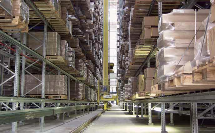
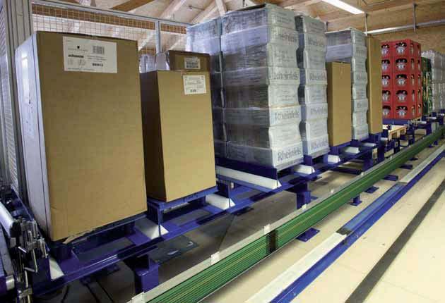
5 INSTALLATION PHOTOS VKS 10 5
6 TECHNICAL DATA VKS 10 Sections Standard lengths: 6 m Cold stores: 4 m 34 (3) Left side Right side HS= with ground (PE) Attention: Joints to be ordered separately (see page 8). Max. Nominal Conductor cross section Type No. of continuous Voltage mm 2 Weight Order-No. Conductors at 35 C L1-L3 Ground 5-10 (5) Conductor current A V material kg/m (4) VKS 10-4/ 60-6 HS x 16 1 x 16 - Cu VKS 10-4/100-6 HS x 25 1 x 16 - Cu 2, VKS 10-4/120-6 HS x 30 1 x 16 - Cu 2, VKS 10-4/140-6 HS x 35 1 x 16 - Cu 2, VKS 10-5/ 60-6 HS x 16 1 x 16 1 x 16 Cu 2, VKS 10-5/100-6 HS x 25 1 x 16 1 x 16 Cu 2, VKS 10-5/120-6 HS x 30 1 x 16 1 x 16 Cu 2, VKS 10-5/140-6 HS x 35 1 x 16 1 x 16 Cu 2, VKS 10-6/ 60-6 HS x 16 1 x 16 2 x 16 Cu VKS 10-6/100-6 HS x 25 1 x 16 2 x 16 Cu VKS 10-6/120-6 HS x 30 1 x 16 2 x 16 Cu VKS 10-6/140-6 HS x 35 1 x 16 2 x 16 Cu VKS 10-7/ 60-6 HS x 16 1 x 16 3 x 16 Cu VKS 10-7/100-6 HS x 25 1 x 16 3 x 16 Cu VKS 10-7/120-6 HS x 30 1 x 16 3 x 16 Cu VKS 10-7/140-6 HS x 35 1 x 16 3 x 16 Cu VKS 10-8/ 60-6 HS x 16 1 x 16 4 x 16 Cu VKS 10-8/100-6 HS x 25 1 x 16 4 x 16 Cu VKS 10-8/120-6 HS x 30 1 x 16 4 x 16 Cu VKS 10-8/140-6 HS x 35 1 x 16 4 x 16 Cu VKS 10-9/ 60-6 HS x 16 1 x 16 5 x 16 Cu VKS 10-9/100-6 HS x 25 1 x 16 5 x 16 Cu VKS 10-9/120-6 HS x 30 1 x 16 5 x 16 Cu VKS 10-9/140-6 HS x 35 1 x 16 5 x 16 Cu VKS 10-9/200-6 HS (2) x 25 1 x 25 2 x 16 Cu VKS 10-9/240-6 HS (2) x 30 1 x 30 2 x 16 Cu VKS 10-9/280-6 HS (2) x 35 1 x 35 2 x 16 Cu VKS 10-10/ 60-6 HS x 16 1 x 16 6 x 16 Cu VKS 10-10/100-6 HS x 25 1 x16 6 x 16 Cu VKS 10-10/120-6 HS x 30 1 x 16 6 x 16 Cu VKS 10-10/140-6 HS x 35 1 x 16 6 x 16 Cu VKS 10-10/200-6 HS (2) x 25 1 x 25 3 x 16 Cu VKS 10-10/240-6 HS (2) x 30 1 x 30 3 x 16 Cu VKS 10-10/280-6 HS (2) x 35 1 x 35 3 x 16 Cu (2) (3) (4) At 80% duty cycle 2 conductors per phase. Powerail projecting length 34 mm at 20 C ambient. Consult factory in case of circuits incl. N conductors. (5) Not with UL-approval; UUL= 600 V Supplement type designations, e.g. 2 m VKS 10-6/60 with PE (ground) VKS 10-6/60-2 HS Order-No Short lengths will be produced out of the next larger rail section.
 PE (ground) PE (ground) PE (ground) PE (ground) Free 5 5 5 5 Free Free 6 6 6 Free Free Free 7 7 Free Free Free Free 8 Free Free Free Free Free Free Free Free Free Free")
7 STANDARD SECTIONS VKS 10 Right side Left side Ø 15, x 14 = ,5 VKS 10-4/ VKS 10-5/ VKS 10-6/ VKS 10-7/ VKS 10-8/ L1 L1 L1 L1 L1 L2 L2 L2 L2 L2 L3 L3 L3 L3 L3 PE (ground) PE (ground) PE (ground) PE (ground) PE (ground) Free Free Free Free Free Free 7 7 Free Free Free Free 8 Free Free Free Free Free Free Free Free Free Free 6,5 24, Ø 15, x 14 = ,5 VKS 10-9/ VKS 10-9/ VKS 10-10/ VKS 10-10/ L1 L1 L1 L1 L2 L2 L2 L2 L3 L3 L3 L3 PE (ground) PE (ground) PE (ground) PE (ground) 5 L1 5 L1 6 L2 6 L2 7 L3 7 L Free Free ,5 24,5 37 7
 Inside bend R Outside bend R Bends are supplied with straight ends, each 250 mm long. Type R mm (2) Order-No.")

8 CURVED SECTIONS AND JOINTS VKS 10 Curved sections vertical in accordance with your design drawings Copper cross section min. 25 mm 2 Max. length of bend = 5.3 m Hanger distance 0.6 m Max. angle = 180 Inside bend = conductors inside Outside bend = conductors outside (not shown) Inside bend R Outside bend R Bends are supplied with straight ends, each 250 mm long. Type R mm (2) Order-No. Inside bend (as shown) Outside bend Joints (3) 150 Plug-in joint for 140 A Plug-in joint for A and A Type No. of poles Weight kg Order-No. SV 10-4/ , SV 10-4/ , SV 10-4/ , SV 10-5/ , SV 10-5/ , SV 10-5/ , SV 10-6/ , SV 10-6/ , SV 10-6/ , SV 10-7/ , SV 10-7/ , SV 10-7/ , SV 10-8/ , SV 10-8/ , SV 10-8/ , SV 10-9/ , SV 10-9/ , SV 10-9/ , SV 10-9/ , SV 10-9/ , SV 10-10/ , SV 10-10/ , SV 10-10/ , SV 10-10/ , SV 10-10/ , Conductor rails connected in parallel (2) Smaller radius on request 3) In case of hall expansion joints please consider expansion sections (on request).


9 FIXPOINT HANGERS, SLIDING HANGERS, END CAPS, END FEEDS VKS 10 Fixpoint hanger on C-rail consisting of hanger clamp and fixing screw and C-rail Sliding hanger on C-rail consisting of hanger clamp and C-rail Fixing screw C-rail 28/15 VEPS 10-H VAS 10-H Fixpoint hanger for support profile VTP 10 consisting of hanger and fixing screw Ø14 Fixing screw 30 Support profile VEPS 10-VTP VAS 10-VTP End cap Can be used right or left handed. Supplied loose as individual part with fixing screws. End feed Terminal box supplied loose, only in conjunction with line feed VLS (2) , ,5 Sliding hanger for support profile VTP 10 consisting of hanger clamp 27, ,5 1,5 46,5 116 length length VES 10 L VEKS 10-10/ (2) Cable glands, 2 x ST-M 40 x 1.5 for D = mm 1 x ST-M 20 x 1.5 for D = 7-13 mm Please order VLS line feed separately. 9
 for 140 A, 25 mm 2 (up to cable Ø 8.2 mm) for 100 A - 120 A, or feed bolts for 60 A powerail 1 m section to be ordered separately. right side length 1m 250 (350 ) left side Type No.")
10 2 0 0 LINE FEED VKS 10 Line feed VLS for direct connection of single core cables M6 terminal with special cable shoe for single core cables; 35 mm 2 (up to cable Ø 8.5 mm) for 140 A, 25 mm 2 (up to cable Ø 8.2 mm) for 100 A A, or feed bolts for 60 A powerail 1 m section to be ordered separately. right side length 1m 250 (350 ) left side Type No. of conductors Current capacity A Weight kg Order-No. VLS 10-4/ , VLS 10-4/ , VLS 10-4/ , VLS 10-5/ , VLS 10-5/ , VLS 10-5/ , VLS 10-6/ , VLS 10-6/ , VLS 10-6/ , VLS 10-7/ , VLS 10-7/ , VLS 10-7/ , VLS 10-8/ , VLS 10-8/ , VLS 10-8/ , VLS 10-9/ , VLS 10-9/ , VLS 10-9/ , VLS 10-9/ , VLS 10-9/ , VLS 10-10/ , VLS 10-10/ , VLS 10-10/ , VLS 10-10/ , VLS 10-10/ , Opening for cable outlet Cable outlet double-sided Line feed VNS with terminal box Cable gland: STR - M 63 x 1,5 for Ø = STR - M 20 x 1,5 for Ø = 5-13 Connection cable to be supplied by customer Cable connection: Main current: M10 Control current: M 5 1 m section to be ordered separately. right side left side Type No. of poles Current capacity A Weight kg Order-No. VNS 10-4/ , VNS 10-5/ , VNS 10-6/ , VNS 10-7/ , VNS 10-8/ , VNS 10-9/ , VNS 10-9/ , m VNS 10-10/ , VNS 10-10/ , Cable payout left, standard 10 Length of the cap

11 TRANSFER FUNNELS VKS 10 Transfer funnel for current collector KESL 32-63/14 max. speed v= 100 m/min. Conductor rails for funnels (all cross sections 25 mm 2, length 1365 mm) Type Order-No. No. of conductors No. of conductors No. of conductors No. of conductors No. of conductors No. of conductors No. of conductors Tolerances: x = ± 10 mm y = ± 10 mm X Y Y X Auxiliary support and fixing claw to be ordered seperately 600 End cap to order seperately 82 94, ,4 Powerail VKS 10 to be ordered seperately Type see table above Support profile R A 6,5 6,5 B C D Type No.ofconductors A mm B mm C mm D mm Weight kg Order-No. EFTV 10-4-KSTU 30/63-14 L , EFTV 10-4-KSTU 30/63-14 R , EFTV 10-5-KSTU 30/63-14 L , EFTV 10-5-KSTU 30/63-14 R , EFTV 10-6-KSTU 30/63-14 L , EFTV 10-6-KSTU 30/63-14 R , EFTV 10-7-KSTU 30/63-14 L , EFTV 10-7-KSTU 30/63-14 R , EFTV 10-8-KSTU 30/63-14 L , EFTV 10-8-KSTU 30/63-14 R , EFTV 10-9-KSTU 30/63-14 L , EFTV 10-9-KSTU 30/63-14 R , EFTV KSTU 30/63-14 L , EFTV KSTU 30/63-14 R , Transfer funnel only in combination with powerail section. Higher speeds on request. 11


12 -A- TANGENTIAL ENTRY FUNNEL, POWERAIL SECTION ISOLATION VKS 10 Tangential entry funnel for collector KSTU max. entry speed v = 100 m/min. Copper cross section min. 25 mm Tolerances: x = ± 10 mm y = +8 mm, -7 mm Y 186 X X Y Type No. of poles A Weight kg Order-No. DSEV 10-4 KSTU ,5 1, DSEV 10-5 KSTU ,5 1, DSEV 10-6 KSTU ,5 1, DSEV 10-7 KSTU ,5 1, DSEV 10-8 KSTU ,5 1, DSEV 10-9 KSTU ,5 1, DSEV KSTU ,5 1, Transfer guide VU Type Assignment from top Order-No. 30 (2) For cross travel and terminal lines max. height- and lateral off-set: ± 2 mm max. air gap between the transfer guides: 5 mm VU 10-4 L Schiene VU 10-4 R Schiene VU 10-5 L Schiene VU 10-5 L Schiene VU 10-6 L rail VU 10-6 R rail VU 10-7 L rail VU 10-7 R rail VU 10-8 L rail VU 10-8 R rail VU 10-9 L rail VU 10-9 R rail VU L rail VU R rail Powerail isolating section The position of the isolating sections are to be identified in the order. 30 (2) VSTS 1/10-60 M 0, VSTS 1/ 100 M 0, VSTS 1/ 120 M 0, VSTS 1/ 140 M 0, M = factory assembled; L = supplied loose 12 (2) For specification of the powerail profile see page 6 Length of the conductor dead section (longer dead sections on request).
 on No.")


 143 116 KESR 32-55 F 10-14 HS 10 80 146 53 0,840 10 pole 143 117 Single collector: Phase PE (ground) Current collector KESR 32-55 F 14 0,060 143 111 143 112 KESR-S for connecting cables")

13 CURRENT COLLECTOR VKS 10 Compact current collector KESR 32/55 for reverse run Distance between conductors: 14 mm max. current flat plug bolted connection 32 A FLA 2,5 AEA 2,5 40 A FLA 4,0 AEA 4,0 55 A FLA 6,0 AEA 6,0 Lift and swivel ± 15 mm Contact pressure: approx. 3.5 N per carbon brush PE (ground) on No. 4, other combinations possible The ground collector always moves first when entering the powerail. KESR-F for connecting cables with flat plug see table 1 page 16 Flat plug 6,3 x 0,8 for FLA or bolted connection b a c 15 RF3 DF max Type No. of poles a mm b mm c mm Weight kg Baseplate Order-No. KESR F 4-14 HS ,480 4-pole KESR F 5-14 HS ,540 6-pole KESR F 6-14 HS ,600 6 pole KESR F 7-14 HS ,660 8 pole (no. 8= free) KESR F 8-14 HS ,720 8 pole KESR F 9-14 HS , pole (no. 10= free) KESR F HS , pole Single collector: Phase PE (ground) Current collector KESR F 14 0, KESR-S for connecting cables with bolted connection see table 2 page 16 Type No. of poles a mm b mm c mm Weight kg Baseplate Order-No. KESR S 4-14 HS ,504 4-pole KESR S 5-14 HS ,570 6-pole KESR S 6-14 HS ,636 6 pole KESR S 7-14 HS ,702 8 pole (no. 8= free) KESR S 8-14 HS ,768 8 pole KESR S 9-14 HS , pole (no. 10= free) KESR S HS , pole Single collector: Phase PE (ground) Current collector KESR S/14 0, Compact current collector KESR 63 S for reverse run with adapter plate and clamping block Spare parts Type Order-No. Carbon MK 63 S/ Current collector KESR S/14 PE Current collector KESR S/14 PH Left hand version Ground on No.4 Type No. of poles Configuration Order-No. KESR 63 S HS- KBL KESR 63 S HS- KBL KESR 63 S HS- KBL KESR 63 S HS- KBL KESR 63 S HS- KBL KESR 63 S HS- KBL KESR 63 S HS- KBL Right hand version Ground on No. 7 torque setting: 1,7 Nm (2) (bolted connection) x ,5 Type No. of poles Configuration Order-No. KESR 63 S HS- KBR KESR 63 S HS- KBR KESR 63 S HS- KBR KESR 63 S HS- KBR KESR 63 S HS- KBR KESR 63 S HS- KBR KESR 63 S HS- KBR (2) Only in combination with clamping block and 10 mm 2 connecting cable. Max. cross section of connecting cable 16 mm² (UL = 10 mm 2 ). 13

14 150 CURRENT COLLECTOR VKS 10 Compact current collector KESL for reverse run Distance between conductors: 14 mm max. current flat plug bolted connection 32 A FLA 2,5 AEA 2,5 40 A FLA 4,0 AEA 4,0 55 A FLA 6,0 AEA 6,0 63 A - AEA 10,0 Lift and swivel ± 30 mm Contact pressure: approx. 7 N per carbon brush PE (ground) on no. 4, other combinations possible The ground collector always moves first when entering the powerail RF3 1 Flat plug 6,3 x 0,8 for FLA or bolted connection b a c DF4 max KESL-F for connecting cables with flat plug see table 1 page 16 Type No. of poles a mm b mm c mm Weight kg Baseplate Order-No. KESL F 4-14 HS ,536 4-pole KESL F 5-14 HS ,612 6-pole KESL F 6-14 HS ,688 6 pole KESL F 7-14 HS ,764 8 pole (no. 8= free) KESL F 8-14 HS ,840 8 pole KESL F 9-14 HS , pole (no. 10= free) KESL F HS , pole Single collector: Phase PE (ground) Current collector KESL F/14 0, KESL-S for connecting cables with bolted connection see table 2 page 16 Type No. of poles a mm b mm c mm Weight kg Baseplate Order-No. KESL S 4-14 HS ,553 4-pole KESL S 5-14 HS ,637 6-pole KESL S 6-14 HS ,721 6 pole KESL S 7-14 HS ,803 8 pole (no. 8= free) KESL S 8-14 HS ,885 8 pole KESL S 9-14 HS , pole (no. 10= free) KESL S HS , pole Single collector: Phase PE (ground) Current collector KESL S/14 0, Compact current collector KESL 63 S for reverse run with adapter plate and clamping block left hand version Spare parts Type Order-No. Carbon MK 63 S/ Current collector KESL S/14 PE Current collector KESL S/14 PH Left hand version Ground on No.4 Type No. of poles Configuration Order-No. KESL 63 S HS- KBL KESL 63 S HS- KBL KESL 63 S HS- KBL KESL 63 S HS- KBL KESL 63 S HS- KBL KESL 63 S HS- KBL KESL 63 S HS- KBL torque setting: 1,7 Nm (bolted connection) Right hand version Ground on No x ,5 Type No. of poles Configuration Order-No. KESL 63 S HS- KBR KESL 63 S HS- KBR KESL 63 S HS- KBR KESL 63 S HS- KBR KESL 63 S HS- KBR KESL 63 S HS- KBR KESL 63 S HS- KBR Max. cross section of connecting cable 16 mm² (UL = 10 mm 2 ).
 Contact pressure: approx.")
 A mm 2 mm mm kg black yellow A mm 2 mm mm kg black yellow KST 30 30 2,50 5 ± 20 0,240 152 085 152 086 KST 55 55 6,00 11 ± 20 0,368 154 438 154 439 KST 63 63 10,00 9 ±")
15 CURRENT COLLECTOR VKS 10, CONNECTING CABLES Current collector KST Current collector KSTU for funnels and tangential entry funnels (multi systems) ,5 4, ,2 12 With 2 m connecting cables Lift and swivel: see following table Contact pressure: approx. 5 N With 2 m connecting cables Lift and swivel see Table (in funnels 10 mm to all sides) Contact pressure: approx. 5 N Current Connection cable Lift+ Order-No. Current Connection cable Lift + Order-No. Type capacity A/ d max./ swivel Weight Phase (ground) Type capacity A/ d max./ swivel Weight Phase (ground) A mm 2 mm mm kg black yellow A mm 2 mm mm kg black yellow KST ,50 5 ± 20 0, KST ,00 11 ± 20 0, KST ,00 9 ± 20 0, KSTU 30/ ,50 5 ± 20 0, KSTU 55/ ,00 11 ± 20 0, KSTU 63/ ,00 9 ± 20 0, Connecting cable FLA, highly flexible, for current collectors. (For allocation to current collectors see page 13 and 14) Connecting cable AEA, highly flexible for current collectors FH FLA Length = 1 m with flat plug 6,3 x 0,8 Longer connecting length available. Length: 1 m Longer connecting length available. Table 1 Table 2 Type Cross section Outside Ø Order-No. Weight Cross section Outside Ø Weight Order-No.. mm 2 mm kg Phase PE Type mm black green/yellow mm kg Phase PE black green/yellow FLA 2,5 2,50 4,00 0, AEA 2,5 2,50 4,00 0, FLA 4 4,00 6,00 0, AEA 4,0 4,00 5,50 0, FLA 6 6,00 7,00 0, AEA 6,0 6,00 6,00 0, AEA 10,0 10,00 8,50 0, Flat plug, single Type for cable cross section Order-No. mm 2 FH 2,5 2, FH 4-6 4,00 + 6, FH 2,5 FH 4,0-6,0 Application area: -15 C to + 70 C. 15


16 ACCESSORIES FOR CURRENT COLLECTORS VKS 10 Collector bracket for current collectors KST see page 15 Carbon brushes KMK PH RH 76 with ground Ground-marking KMK PE Design R shown 10 RH Type A mm B mm C mm Weight kg Order-No. UMA 12 HS-B L , UMA 12 HS-B R , UMA 12 HS-B L , UMA 12 HS-B R , UMA 12 HS-B L UMA 12 HS-B R UMA 12 HS-B UMA 12 HS-B L UMA 12 HS-B R UMA 12 HS-B L UMA 12 HS-B R UMA 12 HS-B L UMA 12 HS-B R , Type 51 For current collector KST 30 - KST 63 and KSTU Carbon brush thickness MK 55 PH / PE MK 63 PH / PE RH mm Weight kg Order- No. KMK PH 4,40 mm 4,00 0, KMK PE KST 30 - KST 63 and KSTU ,40 mm 4,00 0, MK 55 F/14.28 KESR 32-55F KESL 32-55F 4,20 mm 3,50 0, MK 63 S/14.28 KESR 32-63S KESL 32-63S 4,20 mm 3,50 0, Springs Pressure spring DF Tension spring RF Type For current collector S D L mm mm mm Order-No. DF 2 KESR RF 3 KESR DF 4 KESL ,10 6,40 41,


.")
17 SUPPORT PROFILE FOR HIGH BAY STORAGE VKS 10 Accessories VKS 10 Type Order-No. Connector cap Plug-in joint VKS 10/ 10-60A Plug-in joint VKS 10/ A Plug-in joint VKS 10/ 140 A Connection bolts, complete for VLS 10/ Connection bolts, complete for VLS 10/ Connection bolts, complete for VNS 10/ Plastik glue for tangential funnel DSEV Support profile Length: 6 m ,5 240 Type Weight kg/m Order-No. VTP 10 4, ,5 Ø14 Support profile VTP 10 for feed VNS 10, VLS 10 Support profile Type Order-No. Version for initial / end section Version on the track Terminal box not included not applicable on the track Connector Only as single component otherwise included in the attachment material of the support profile (see page 18). Hanger Only as single component otherwise included in the attachment material of the support profile (see page 18) x x x 30 9 x 30 VTPV VTPA
18 SUPPORT PROFILE ATTACHMENTS VKS 10 VTPB-P Fig. 1 x VTPB Fig. 4 x VTPB-SPR Fig. 2 max Klemmbereich Fixing claw 75 Rack upright 35 max (2) VTPB-SPW Fig. 3 View x View y Clamping profile M10 max M10 30 M10 30 M max. 8 VTPB-S 1/2 Fig. 5 S1, S Type Fig. Clamping range Weight kg Order-No. VTPB-P 1 max. 8 0, VTPB-SPR 2 max. 15 2, VTPB 130-SPW 3 max. 15 1, VTPB , VTPB , VTPB , VTPB , VTPB , VTPB , VTPB , VTPB , VTPB , VTPB , VTPB , VTPB , VTPB , VTPB S 1/2 5 max.8 0, (2) Bigger clamping range on request. Locking torque of the round-head screw M 10, MA= 18 Nm


19 VAHLE-APOS POSITIONING SYSTEM Operating principle VAHLE-APOS consists of a code strip with magnetic length coding and a reading head with integrated logic, which transmits the position to the control system via interface. The intelligent reading head determines the position from the code strip and evaluates it for downstream control systems for processing. VAHLE-APOS in VKS pole VAHLE-APOS in VKS pole absolute positioning identification upto 524 m retrofit absolute position at engaging or after a outage directly available safe position identification aswell with wetness or dust travel speed upto 6 m/s For further details please refer to VAHLE-APOS catalog (7a) 19
 position encoding")
 with seperate")
 Earthing of the code rail: Connect the WCS code")
.")
 Fixing clip for plastic")
 0,040 302 106")


20 POSITIONING SYSTEM Cost-efficient installation of different positioning systems position encoding system (WCS) position encoding system (BCB) fixing clip (see below) position encoding system (WCS) at lateral arrangement position encoding system (WCS 3) with seperate Aluminium-Profile. (drilling by others) Earthing of the code rail: Connect the WCS code rail at least every 30 m to the potential of the system of low resistance. (Part-No.: E- WCS 3/VTP 10/ ). Fixing clip for laminate band Position encoding band Fixing distance 0.2 m WCS 1x per conductor section BCB(2) Fixing clip for plastic laminate band 0, Type Weight kg/m Order-No. Plastic laminate band with special perforation (WCS 3) 0, Screws for fixation 0, Barcode band (BCB) 0, Installation tool For use with support profile Installation tool For use with support profile Joint cap assembly tool 0, Copper connector mounting lever 1, Installation comb Installation comb, set for VKS 10 0, To adjust the air gap at the joint 20 (2) Max.travel length 327 m. Max.travel length m.
21 QUESTIONNAIRE Company: Tel: Date: Fax: Internet: 1. Number of powerail systems: 2. Type of equipment to be powered: 3. Operating voltage: Volts, Frequency: Hz Three phase voltage: AC voltage: DC voltage: 4. Track length: 5. Number of conductors: (Neutral: control: ground: 6. Mounted position of powerail: Powerail pendant, collector cable facing to the bottom Powerail pendant, collector cable lateral payout Support distance m Other: 7. Number of consumers per system: 8. Indoor: Outdoor: 9. Other operating conditions (humidity, dust, chemical influence etc.) 10. Ambient temperature: C min. C max. 11. Hall expansion gaps: pc. max. expansion 12. Position and number of feed points : 13. Position and number of dead sections (e.g. maintenance bays) 14. How will the conductor system be arranged? : 15. Brackets required: yes no c/c distance beam / powerail Flange width of beam 16. Travel speed (long travel): in curves: at transfers: 17. Power consumption of the individual consumers: 18. Max. Voltage drop from the powerail feed point to the consumer considering starting current: 3% or % referring to nominal voltage. Crane 1 Crane 2 Motor data Power kw Nominal current Starting current Type of Power Nominal current Starting current Motors (2) KW A cos ϕ N % ED A cos ϕ A A cos ϕ N % ED A cos ϕ A Type of Motors (2) Hoist motors Auxiliary hoist Long travel Cross travel Mark with * those motors which can run simultaneously. Mark with those motors which can start up simultaneously. Further remarks: Signature: Sketch required (2) Note type of Motor: K for Squirrel cage motor, S for slipring motor, F for frequency controlled motor. We reserve the right for technical changes due to further developments. Please copy and fax this questionnaire. 21
22 22 NOTES
23 NOTES 23
24 Catalog No. 3a/E 2011 MANAGEMENTSYSTEM Products and Service 1 Open conductor systems Open conductor systems 2 Insulated conductor systems U 10 FABA 100 U 15 - U 25 - U 35 U 20 - U 30 - U 40 3 Compact conductor systems VKS 10 VKS - VKL 4 Enclosed conductor systems KBSL - KSL KBH MKH LSV - LSVG 5 Contactless power supply Contactless power supply (CPS ) 6 Data transmission VAHLE Powercom Slotted Microwave Guide (SMG) 7 Positioning systems VAHLE APOS 8 Festoon systems and cables 9 Reels 10 Others Catalog No. 1a 2a 2b 2c 2d 3a 3b 4a 4b 4c 4d 5a 6a 6b 7a Festoon systems for - tracks 8a Festoon systems for flat cables on - tracks 8b Festoon systems for round flat cables on - tracks 8c Festoon systems for - tracks 8d Cables 8e Spring operated cable reels 9a Motor powered cable reels 9b Battery charging systems 10a Heavy enclosed conductor systems 10b Tender 10c Contact wire 10d Assemblies/Commissioning Spare parts/maintenance service 0311 Printed in Germany /00-E 3/11 certified by DQS according to Din EN ISO 9001:2008 OHSAS 18001:2007 (Reg. Nr QM 08/BSOH) PAUL VAHLE GMBH & CO. KG Westicker Str. 52 D KAMEN/GERMANY TEL. (+49) 23 07/70 40 Internet: info@vahle.de FAX (+49) 23 07/
25 Catalog No. 3a/E 2009 MANAGEMENTSYSTEM certified by DQS according to Din EN ISO 9001:2008 OHSAS 18001:2007 (Reg. Nr QM 08/BSOH) Products and Service 1 Open conductor systems Open conductor systems 2 Insulated conductor systems U 10 FABA 100 U 15 - U 25 - U 35 U 20 - U 30 - U 40 3 Compact conductor systems VKS 10 VKS - VKL 4 Enclosed conductor systems KBSL - KSL - KSLT KBH MKH LSV - LSVG 5 Contactless power supply Contactless power supply (CPS ) 6 Data transmission VAHLE Powercom Slotted Microwave Guide (SMG) 7 Positioning systems VAHLE APOS 8 Festoon systems and cables 9 Reels 10 Others Catalog No. 1a 2a 2b 2c 2d 3a 3b 4a 4b 4c 4d 5a 6a 6b 7a Festoon systems for - tracks 8a Festoon systems for flat cables on - tracks 8b Festoon systems for round flat cables on - tracks 8c Festoon systems for - tracks 8d Cables 8e Spring operated cable reels 9a Motor powered cable reels 9b Battery charging systems 10a Heavy enclosed conductor systems 10b Tender 10c Contact wire 10d Assemblies/Commissioning Spare parts/maintenance service 0909 Printed in Germany /00-E DS 300 9/09 POWERAIL Powerail Ltd. High Road, Finchley, London, N12 8PT, Phone /1246 Fax enquiries@powerailltd.com
POWERAIL ENCLOSED CONDUCTOR SYSTEM VKS 10
 POWERAIL ENCLOSED CONDUCTOR SYSTEM VKS 10 POWERAIL ENCLOSED CONDUCTORS VKS 10 CONTENTS Page General 2, 3 Planning guide 4 Technical data, standard sections 6, 7 Curved sections 8 Jointing material 8 Hangers
POWERAIL ENCLOSED CONDUCTOR SYSTEM VKS 10
 POWERAIL ENCLOSED CONDUCTOR SYSTEM VKS 10 POWERAIL ENCLOSED CONDUCTORS VKS 10 CONTENTS Page General 2, 3 Planning guide 4 Technical data, standard sections 6, 7 Curved sections 8 Jointing material 8 Hangers
Compact Conductor System VKS10 SYSTEMS IN MOTION
 Compact Conductor System VKS10 SYSTEMS IN MOTION 3a/en 2016 Content General...3 System diagram...5 Sections...6 Pole configuration...7 Curved sections...8 Fixpoint hanger...9 End cap...9 Sliding hanger...9
INSULATED CONDUCTOR SYSTEMS U10
 INSULATED CONDUCTOR SYSTEMS U10 INSULATED CONDUCTORS U 10 Index Page Basic description 3 Insulated conductors 4 Feed-in joint splice 5 Expansion section 5 Isolating assembly 5 Transfer guide 6 Compact
Multi Support Profile VMT SYSTEMS IN MOTION
 Multi Support Profile VMT SYSTEMS IN MOTION 3c/en 2013 2 Multi Support Profile (VMT) Content The VAHLE solution for automation...3 System layout...4 Technical data...4 VMT - Multi Support Profile...5 Joint
BATTERY CHARGING SYSTEMS. for Automatic Guided Vehicles
 BATTERY CHARGING SYSTEMS for Automatic Guided Vehicles 19 12 GENERAL INFORMATION The operation of Automatic Guided Vehicles (AGVs) requires high utilization of these vehicles in order to achieve an optimum
POWERAIL ENCLOSED CONDUCTOR SYSTEMS VKS VKL
 POWERAIL ENCLOSED CONDUCTOR SYSTEMS VKS VKL 19 12 POWERAILS VKS & VKL INDEX VKS VKL Basic description 3, 4 3, 4 Layout planning 5 5 Engineering data, Powerail standard sections 6, 7 23 Powerail curves
VAHLE POWERCOM 485. Digital Data Transmission System
 VAHLE POWERCOM 485 Digital Data Transmission System 19 12 VAHLE POWERCOM 485 GENERAL INFORMATION VAHLE POWERCOM 485 Digital Data Transmission using VAHLE Conductor Systems VAHLE POWERCOM 485 is the latest
POWERAIL ENCLOSED CONDUCTOR SYSTEM KBH
 POWERAIL ENCLOSED CONDUCTOR SYSTEM KBH POWERAIL KBH Contents Page Contents Page System photo 2 Removing sections, Conductor dead sections 14 General 2, 3 Anti-condensation sections, Expansion sections
POWERAIL ENCLOSED CONDUCTOR SYSTEM KBH
 POWERAIL ENCLOSED CONDUCTOR SYSTEM KBH POWERAIL KBH Contents Page Contents Page System photo 2 Removing sections, Conductor dead sections 14 General 2, 3 Anti-condensation sections, Expansion sections
MACHT STROM MOBIL. Battery Charging Systems
 MACHT STROM MOBIL Battery Charging Systems 10a/en 15 2 Battery Charging Systems Content...Seite General...3 Models...4 General installation instructions...7 The operation of Automatic Guided Vehicles (AGVs)
MACHT STROM MOBIL. Enclosed conductor system KBH SYSTEMS IN MOTION
 MACHT STROM MOBIL Enclosed conductor system KBH SYSTEMS IN MOTION 4b/en 2013 2 Enclosed conductor system KBH Content... Page Description of the Conductor system... 3 Technical description... 4 Technical
4 pole insulated conductor rails ULA 35A, 50A, 80A, 100A
 Table of contents General information... 3 Elements of the conductor rail supply line... 3 Innovative connection method... 3 Technical properties... Construction of the line section... Line section...
4 pole insulated conductor rails UNILIFT-ULA 35A, 50A, 80A, 100A
 2 Table of contents General information... 4 Elements of the conductor rail supply line... 4 Innovative connection method... 5 Technical properties... 6 Construction of the line section... 6 Line section...
Energy Supply Systems
 Energy Supply Systems SINGLE POLE INSULATED CONDUCTOR RAIL 815 100 amps KAT0815-0001b-E Conductor rail system in a high bay storage Slip ring with conductor rail system in a stretch-foil packing machine
VAHLE POWERCOM 485. Digital Data Transmission System
 VAHLE POWERCOM 485 Digital Data Transmission System 19 12 VAHLE POWERCOM 485 GENERAL INFORMATION VAHLE POWERCOM 485 Digital Data Transmission using VAHLE Conductor Systems VAHLE POWERCOM 485 is the latest
POWERAIL CONDUCTOR SYSTEMS MKLD MKLF MKLS
 POWERAIL CONDUCTOR SYSTEMS 19 12 POWERAIL INDEX Page Powerail versions 3 Basic description 3 Technical data 3 Powerail types, cat. nos. and weights 4 Engineering data and configurations 5 Standard sections,
MACHT STROM MOBIL. Insulated Conductor Systems U10
 MACHT STROM MOBIL Insulated Conductor Systems U10 2a/en 2014 Table of Contents Basic description...2 Technical Data...4 Joint Feed...5 Feed Terminal...5 Isolating Assembly...5 Distance Bracket...5 Expansion
Energy Supply Systems
 Energy Supply Systems MULTIPOLE CONDUCTOR RAIL 831 10-125 amps KAT0831-0001b-E 13 pole multipole conductor rail in 33 package distribution centres of the postal service (Post AG) 9 pole multipole conductor
4 pole insulated conductor rails ULA 35A, 50A, 80A, 100A
 Table of contents General information... 3 Elements of the conductor rail supply line... 3 Innovative connection method... 3 Technical properties... Construction of the line section... Line section...
INSULATED CONDUCTOR SYSTEMS U 20 U 30 U 40
 INSULATED CONDUCTOR SYSTEMS U 20 U 30 U 40 INSULATED CONDUCTORS U 20 U 30 U 40 INDEX U 20 U 30 U 40 Page Page Page Basic description 4 4 4 Selection of conductors 5-10 5-10 5-10 Conductors 11 24 34, 35
Bolted, snap-in and guarter turn type hangers are available. Standard support distance for U12 is 600mm, in curves 300mm.
 General Komay insulated conductors U12 are designed in accordance with today s international safety requirements. The shroud which envelopes the various conductors is an excellent insulator. Therefore
INSULATED CONDUCTORS U 15 - U 25 - U 35
 INSULATED CONDUCTORS U 15 - U 25 - U 35 INSULATED CONDUCTORS U 15 U 25 U 35 Index U 15 U 25 U 35 Page Page Page Basic description 4 4 4 Selection of conductors 5 23 34 Insulated conductors 5 23 34 Joint
MACHT STROM MOBIL. Spring Operated Cable Reels
 MACHT STROM MOBIL Spring Operated Cable Reels 9a/en 2013 2 Spring Operated Cable Reels Content...Page Spring operated cable reels...3 Reel selection charts...5 Typical applications...6 Model explanation...7
Multipole Conductor Rail MultiLine Program 0831
 Multipole Conductor Rail MultiLine Program 0831 Contents Description / Technical Data Description....2 Technical Data....3 Conductor Rails Rails complete with pre-mounted Connector...4 Power Feeds....5
Technical data. DKK compact conductor lines engb IS eps
 Technical data DKK compact conductor lines 4146644.eps 10910 engb 0 540 44 714 IS 9 Contents 1 Technical information Straight sections 4 Curved sections 5 4 Powerfeeds 6 5 Ramp sections, expansion joints
GENERAL INDEX TR60. 6 YELLOW LINE Continuous Conductors. Max 5 Poles. 8 BLUE LINE Pre-Mounted Conductors TR85H5P. YELLOW LINE Continuous Conductors
 2 Automation - Lift - Handling System GENERAL INDEX 2 DESCRIPTION 3 BUSBAR LINE VERSIONS LINE TYPE / AMPERAGE COVERAGE 5 TR60 40 A 50 A 60 A 70 A 100 A 140 A 160 A 200 A 320 A 6 YELLOW LINE Continuous
MACHT STROM MOBIL. Enclosed conductor system KBH SYSTEMS IN MOTION
 MACHT STROM MOBIL Enclosed conductor system KBH SYSTEMS IN MOTION 4b/en 2016 2 Enclosed conductor system KBH Inhalt Enclosed conductor system KBH... 3 Technical description... 4 Technical data... 6 Jointing
Multipole Conductor Rail MultiLine Program 0831
 Multipole Conductor Rail MultiLine Program 0831 ProShell - the modular carrier profile as a system supplement for program 0812 and 0831 ProShell catalog KAT0800-0003-E available for download at www.conductix.com
POWERAIL ENCLOSED CONDUCTOR SYSTEMS KBSL KSL KSLT
 POWERAIL ENCLOSED CONDUCTOR SYSTEMS KBSL KSL KSLT POWERAILS KBSL KSL KSLT INDEX Page Page Powerail versions (Photos) 2 Transfer funnels 14 Basic description 2, 3 Anti-condensation section 15 Technical
Insulated Conductor Rail SinglePowerLine Program 0812
 Insulated Conductor Rail SinglePowerLine Program 0812 Table of Contents System Description 5 Technical Data 6 General Instructions 7 System Structure 8 Components and their use....8 Insulated Conductor
Insulated Conductor Rail SinglePowerLine Program 0813
 Insulated Conductor Rail SinglePowerLine Program 0813 Table of Contents System Description 5 Technical Data 6 General Instructions 7 System Structure 8 Components and their use... 8 Insulated Conductor
Insulated Conductor Rail SinglePowerLine Program 0812
 Insulated Conductor Rail SinglePowerLine Program 0812 2 Table of Contents System Description 5 Technical Data 6 General Instructions 7 System Structure 8 Components and their use... 8 Insulated Conductor
CONTENTS 1 GENERAL 2 STANDARDS. 3 TECHNICAL FEATURES 3.1 Basic Design Data 3.2 Standard Accessories 3.3 Tolerances
 CONTENTS 1 GENERAL 2 STANDARDS 3 TECHNICAL FEATURES 3.1 Basic Design Data 3.2 Standard Accessories 3.3 Tolerances 4 MOTOR DESIGN 4.1 Stator Casing 4.2 Stator Core with Winding 4.3 Stator Winding and Insulation
1 Product Description System Layout Safety Instructions Intended Use Installation... 3
 Order Number 0812xx- Contents 1 Product Description... 2 2 System Layout... 2 3 Safety Instructions... 3 4 Intended Use... 3 5 Installation... 3 5.1 Hanger Clamp... 3 5.2 Cutting of Conductor Rail... 4
1 Product Description Check of the supplied Parts Notes Intended Use Current Collector... 3
 Order number 0813xx-... Contents 1 Product Description... 2 2 Check of the supplied Parts... 2 3 Notes... 2 4 Intended Use... 2 5 Current Collector... 3 6 Installation Sequence... 3 7 Pickup Guide... 7
VAHLE MOTOR POWERED CABLE REELS
 VAHLE MOTOR POWERED CABLE REELS INDEX Page Introduction 2, 3 Cable selection 4 Typical applications 5 Questionnaire 6, 7 Model explanation 8 36 Reel selection charts monospiral wrap, horizontal payout
CABLE CARRIERS for -Track
 CABLE CARRIERS for -Track Contents 2 VAHLE FESTOON SYSTEMS General Information 3 Questionnaire 4 S 1 Track & Accessories 5 9 LS 1 Cable carriers & Accessories Polyamid type 10 S 1 Cable carriers & Accessories
Conductor Rail System for Shuttles MultiLine Program 0835
 MultiLine Program 0835 Table of Contents General Information 5 System Advantages 5 Main Features at a Glance 6 Technical Data 7 Conductor Rail 8 End Segment (End Power Feed) 8 Rail Connector 9 Standard
CONTENTS 1 GENERAL 2 STANDARDS. 3 TECHNICAL FEATURES 3.1 Basic Technical Data 3.2 Standard Accessories 3.3 Tolerances
 CONTENTS 1 GENERAL 2 STANDARDS 3 TECHNICAL FEATURES 3.1 Basic Technical Data 3.2 Standard Accessories 3.3 Tolerances 4 MOTOR DESIGN 4.1 Stator Casing 4.2 Stator Core with Winding 4.3 Stator Winding 4.4
FABA. Standard Components. Conductor Bar System. publication #FABASC-04 1/1/04 Part Number: Copyright 2003 Electromotive Systems
 FABA Conductor Bar System Standard Components publication #FABASC-04 1/1/04 Part Number: 000-2201 Copyright 2003 Electromotive Systems Table of Contents Section IS 100 A - Introduction General Information
ALINOX INSULATED CONDUCTOR RAIL FOR ELECTRICAL FEEDING OF CRANES
 ALINOX INSULATED CONDUCTOR RAIL FOR ELECTRICAL FEEDING OF CRANES 2 ALINOX INSULATED CONDUCTOR RAIL Features, advantages and benefit The insulated conductor rail system ALINOX is the most suitable solution
CABLE CARRIERS for -Track
 CABLE CARRIERS for -Track VAHLE FESTOON SYSTEMS Contents General Information 3 Questionnaire 4 S 1 Track & Accessories 5 9 LS 1 Cable carriers & Accessories Polyamid type 10 S 1 Cable carriers & Accessories
Pro-Ductor Insulated flat conductor bar for 4, 7 or 10 conductors
 Darwinstraat 10 NL 6718 XR Ede The Netherlands Flexible with energy! Phone +31 (0)342 403900 Fax +31 (0)342 403912 email info@akapp.com URL www.akapp.com Pro-Ductor Insulated flat conductor bar for 4,
Enclosed Conductor System MKH SYSTEMS IN MOTION
 MACHT STROM MOBIL Enclosed Conductor System MKH SYSTEMS IN MOTION 4c/en 4c/de 2016 2015 Enclosed conductor system MKH Content Description of the conductor system... 3 Technical Data... 5 Technicall data
Heavy-Duty Conductor Rail CopperHead
 Heavy-Duty Conductor Rail CopperHead Table of Contents CopperHead Conductor Systems 4 Heavy-Duty Conductor Rails...4 Some Advantages of CopperHead Rail Systems...4 Product Pre-Selection...4 Technical
Technical specifications
 KINGDOM OF SAUDI ARABIA THE SAUDI FUND FOR DEVELOPMENT ( SFD) ITB -207-7 Technical specifications Project name: Reconstruction, Furniture and Equipping of Three Schools Photovoltaic Solar System for Holly
ENYSTAR Load Centers up to 250 A
 PASSION FOR POWER. up to 250 A according to IEC 61439-3 for commercial and industrial buildings Download at www.hensel-electric.en made in GERMANY since 1931 up to 250 A according to IEC 61439-3 for commercial
Conductor Bar Safe-Lec 2 Hevi-Bar II
 Conductor Bar Safe-Lec 2 Hevi-Bar II Contents Safe-Lec 2 and Hevi-Bar II Overview 3 Conductor Bar Summary Chart 4 Quick Quote Software 5 Quotations Data Sheet 6-7 Safe-Lec 2 8-33 Safe-Lec 2 System Components
Page. Circuit-Breakers M4 2 for motor protection. Auxiliary contacts 3 Signalling switch Auxiliary releases
 Circuit Breakers M4 Page Circuit-Breakers M4 2 for motor protection Auxiliary contacts 3 Signalling switch Auxiliary releases Insulated 3-pole busbar system 4 Terminal block DIN-rail adapters 5 Busbar
Technical data Demag DC-Com 1 to DC-Com 10 chain hoist
 Technical data Demag DC-Com 1 to DC-Com 10 chain hoist 42647546.jpg 090506 EN 203 571 44 714 IS 817 Design overview Single-fall design 1 2 4 3 6 5 7 8 9 14 16 15 13 1 Electrical equipment cover 2 Brake
Conductor: plain wire, fine stranding as per VDE 0295 class 6 from 50 mm² fine stranding according to VDE 0295 class 5
 Semoflex DRUM Description Application In dry and damp rooms, explosive security areas and also outdoors for heavy-duty units such as hoisting gears, transportation systems, motorized cable reels, rail
HEAVY DUTY POWER RELAYS FEATURES
 VDE VC HEAVY DUTY POWER RELAYS VC RELAYS Faston terminal Screw terminal mm 9 FEATURES VC power relays are designed for controlling heavy duty loads safely: Contact gap of 3 mm or more -point contacts for
1 Product Description System Layout Safety Instructions Intended Use Installation... 3
 Part Number 0812xx- Contents 1 Product Description... 2 2 System Layout... 2 3 Safety Instructions... 3 4 Intended Use... 3 5 Installation... 3 5.1 Hanger Clamp... 3 5.2 Cutting of Conductor Rail... 4
1 Product Description Check of the supplied Parts Notes Intended Use Current Collector... 3
 Part number 0813xx-... Contents 1 Product Description... 2 2 Check of the supplied Parts... 2 3 Notes... 2 4 Intended Use... 2 5 Current Collector... 3 6 Installation Sequence... 3 7 Pickup Guide... 6
Electromotive Systems ELECTROBAR ELITE Conductor Bar System
 Electromotive Systems ELECTROBAR ELITE Conductor Bar System ELECTROMOTIVE SYSTEMS ELECTROBAR ELITE ENCLOSED CONDUCTOR BAR SYSTEMS Magnetek s Electromotive Systems division proudly offers ELECTROBAR Elite,
POWER BAR SYSTEM ECONOMICAL ENCLOSED CONDUCTOR SYSTEM FOR MOBILE EQUIPMENT M O B I L E E L E C T R I F I C A T I O N
 A e r o B A R POWER BAR SYSTEM ECONOMICAL ENCLOSED CONDUCTOR SYSTEM FOR MOBILE EQUIPMENT M O B I L E E L E C T R I F I C A T I O N AeroBAR Enclosed Conductor Bar System AeroBAR provides many of the advantages
4-Ductor Insulated conductor bar
 Darwinstraat 10 4-Ductor AKAPP 4-Ductor current supply system compact, reliable and safe! AKAPP 4-Ductor is a compact, reliable and safe current supply system for cranes, hoists, monorail systems, conveyor
Underfloor to desk 231
 Technical information Underfloor to desk 231 Series 507 Powertrack Series 507 Powertrack is an underfloor busbar system rated at 63Amp maximum. It is available in Standard or CE (Clean Earth) versions.
Electromotive Systems ELECTROBAR 8-Bar Conductor Bar System
 Electromotive Systems ELECTROBAR 8-Bar Conductor Bar System ELECTROMOTIVE SYSTEMS ELECTROBAR 8-BAR CONDUCTOR BAR SYSTEMS The practical, proven and economical way to deliver electricity to overhead cranes,
Electronic Circuit Breaker ESS20-0..
 Electronic Circuit Breaker ES-0.. Description Electronic circuit breaker type ES-0.. is designed to ensure selective disconnection of individual loads in systems which are powered by a DC 4 V switch-mode
CRANE, CONVEYOR, LIFT & REELING CABLES
 CRANE, CONVEYOR, LIFT & REELING CABLES F-PVC Series... 158 F-TPECY Series...160 P Series...161 PR Series...162 PRRT Series... 164 PRVS Series...166 Reeling/Trailing Cable Enquiry Form...168 P: (09) 264
Steering column and sensor
 Steering column and sensor Type LAB Series 1 x Nominal voltage 12 to 48 volt Output signal digital, analog and direction (option) HE 11874 / 09.2017 2 LAB HE 11874 / 09.2017 Page Content 4 4 5 6 7 7 8
20 HUBER+SUHNER RADOX SOLAR
 All our cables fully comply with the European directives 76/769/EWG, 2003/11/EG, 2000/53/EG, 2003/53/EG and 2002/95/EG (RoHS) and the requirements of REACH Nr. EC1907/2006. 20 RADOX SOLAR cables RADOX
4 Pole / 5 Pole Enclosed Conductor System
 4 / 5 Pole Conductor System 4 Pole / 5 Pole Enclosed Conductor System Enclosed Conductor system with IP23 Finger proof cellular profile. Available in intensities from 20 Amp 200 Amp Data sheet ref : 10
INTRODUCTION. The plug-in connection on the cables and lightning arrestors, allows for easy installation and replacement.
 INTRODUCTION The Power Systems 44 kv MiniSub TM is the most compact system at this voltage available. Utilizing a deadfront termination and lightning arrestor setup, it eliminates the line top or side
Conductor Bar. 8 Bar Side Contact
 Conductor Bar 8 Bar Side Contact Contents Conductor Bar Summary Chart 3 Quick Quote Software 4 Comparison of 8 Bar and Safe-Lec 2 5 Quotations Data Sheet 6-7 Insul 8 8 Bar and Side Contact Overview 8 8
Pro-Ductor Insulated flat conductor bar for 4, 7 or 10 conductors
 Wabtec Netherlands B.V. Darwinstraat 10 NL 6718 XR Ede The Netherlands Flexible with energy! Phone +31 (0)342 403900 Fax +31 (0)342 403912 Email info@akapp.com URL www.akapp.com Pro-Ductor Insulated flat
Conductor Bar Safe-Lec 2 Hevi-Bar II
 Conductor Bar Safe-Lec 2 Hevi-Bar II Contents Safe-Lec 2 and Hevi-Bar II Overview 3 Conductor Bar Summary Chart 4 Quick Quote Software 5 Quotations Data Sheet 6-7 Safe-Lec 2 8-33 Safe-Lec 2 System Components
Festoon systems. Flatform cable festoon systems. Introduction. Flexible with energy!
 Festoon systems Flexible with energy! Introduction Flatform cable festoon systems The AKAPP flatform cable festoon systems provide a safe, effective and economical means of supplying power to cranes, hoists
Type Operating Instructions. Bedienungsanleitung Manuel d utilisation. 2/2-Way Solenoid Valve 2/2-Wege-Magnetventil Électrovanne à 2/2 voies
 Type 5282 2/2-Way Solenoid Valve 2/2-Wege-Magnetventil Électrovanne à 2/2 voies Operating Instructions Bedienungsanleitung Manuel d utilisation 1 OPERATING INSTRUCTIONS The operating instructions contain
Conductor Rail System for Shuttles MultiLine Program 0835
 MultiLine Program 0835 Table of Contents General Information 5 System Advantages 5 Main Features at a Glance 6 Technical Data 7 Conductor Rail 8 End Segment (End Power Feed) 8 Rail Connector 9 Standard
Technical data Demag chain hoist DC-Pro 1, DC-Pro 2, DC-Pro 5, DC-Pro 10, DC-Pro 20 Demag Manulift chain hoist DCM-Pro 1, DCM-Pro 2, DCM-Pro 5
 Technical data Demag chain hoist 1,,, 1, Demag Manulift chain hoist DM-Pro 1, DM-Pro, DM-Pro 46474.eps 1 EN 3 44 714 IS 817 Design overview Single-fall design 1 4 3 6 7 8 9 14 16 1 13 1 Electrical equipment
Type Operating Instructions. Bedienungsanleitung Manuel d utilisation. 2/2-Way Solenoid Valve 2/2-Wege-Magnetventil Électrovanne à 2/2 voies
 Type 5282 2/2-Way Solenoid Valve 2/2-Wege-Magnetventil Électrovanne à 2/2 voies Operating Instructions Bedienungsanleitung Manuel d utilisation Contents 1 Operating Instructions... 2 2 Authorized use...
Conductor Bar Safe-Lec 2 Hevi-Bar II
 Conductor Bar Safe-Lec 2 Hevi-Bar II Contents 2 Safe-Lec 2 and Hevi-Bar II Overview 3 Conductor Bar Summary Chart 4 Quick Quote Software 5 Quotations Data Sheet 6-7 Safe-Lec 2 8-33 Safe-Lec 2 System Components
"...Let things run smoother - HELM technologie"
 Group 14 a -aluminium- ALUMINIUM LIGHT CRANE SYSTEM "...Let things run smoother - HELM technologie" - Individual solution for every workplace - Extreme load-bearing capacity - Extensive accessories upon
Dycon D2430 EN54-4 Fire Alarm Power Supply Series
 Dycon D2430 EN54-4 Fire Alarm Power Supply Series Technical Description Installation and Operating Manual Construction Product Regulation 0359-CPR-00434 Page 1 of 14 Contents 1. General... 3 1.1 Product
Series P215ST Single Pressure Input Condenser Fan Speed Controllers For Single Phase Motors (incl. built-in RFI suppression filter)
") PSC9733 European Refrigeration Controls Catalogue Catalog Section 4 Product Bulletin Series Single Pressure Input Condenser Fan Speed Controllers For Single Phase Motors (incl. built-in RFI suppression
PSC9733 European Refrigeration Controls Catalogue Catalog Section 4 Product Bulletin Series Single Pressure Input Condenser Fan Speed Controllers For Single Phase Motors (incl. built-in RFI suppression
Page 1/6. Temperature sensor baelz 61 with questionnaire for inquiries on page 5 DS 61, 251
 Page 1/6 Temperature sensor with questionnaire for inquiries on page 5 DS 61, 251 Pipe immersion temperature sensor Stainless steel screw-in protection well baelz 251-S5 Stainless steel weld-in protection
Electric Mini Slides MSC-EL
 Electric Mini Slides MSC-EL R10EN 2604 (11.08) The Drive & Control Company Electric Mini Slides, MSC-EL R10EN 2604 (11.08) Mini Slides, MSC-EL Product Description 4 Selection Guide 6 Maximum thrust 6
Ordering information. When placing an order, specify motor type, size and product code according to the following example.
 Ordering information When placing an order, specify motor type, size and product code according to the following example. Example Motor type M3AA 112 MB Pole number 4 Mounting arrangement (IM-code) IM
HBI 22. Integrated Three-phase Synchronous Drive
 HBI 22 Integrated Three-phase Synchronous Drive positioning capability up to 9 Watts rated output power with linear hall sensor system with or without parking brake Motor type Dimension L1 L2 HBI 223 125
SIGMA SERIES DE METER
 SIGMA SERIES DE METER Analogue Meters www.sifamtinsley.co.uk DATASHEET Issue 1.0 Multifunction Meters Transducers & Isolators Temperature Controllers Converters & Recorders Digital Panel Meters Current
manual magnetic linear measurement system MW10
 manual 1 Devices for operating voltage 24V DC for scanning a magnetic strip without reference point Table of contents 1 Warranty information... page 1 2 Identification... page 1 3 Mechanical mounting...
AF09... AF30 3-pole Contactors up to 25 HP / 600 VAC
 AF09... AF0 -pole Contactors up to 25 HP / 600 VAC Contactors and Overload Relays Overview.../0 AF09... AF0 -pole Contactors.../2 Main Technical Data.../8 Main Accessory Fitting Details.../2 Main Accessory.../24
Teepak Totally Enclosed Tube Ventilated High Voltage Induction Motors. A Regal Brand.
 Teepak Totally Enclosed Tube Ventilated High Voltage Induction Motors A Regal Brand www.regalbeloit.com Specifications Range Poles Voltage : Upto 3000 KW : Upto 14 Pole : Upto 11000 Volt Frame : 450 1000
DATASHEET - DILMC9-10(24VDC) Technical data General. Contactor, 3p+1N/O, 4kW/400V/AC3. Catalog No Eaton Catalog No. XTCEC009B10TD.
 Technical data General. Contactor, 3p+1N/O, 4kW/400V/AC3. Catalog No Eaton Catalog No. XTCEC009B10TD.") DATASHEET - DILMC9-10(24VDC) Technical data General Contactor, 3p+1N/O, 4kW/400V/AC3 Part no. DILMC9-10(24VDC) Catalog No. 277468 Eaton Catalog No. XTCEC009B10TD EL-Nummer 4110305 (Norway) Standards IEC/EN
DATASHEET - DILMC9-10(24VDC) Technical data General Contactor, 3p+1N/O, 4kW/400V/AC3 Part no. DILMC9-10(24VDC) Catalog No. 277468 Eaton Catalog No. XTCEC009B10TD EL-Nummer 4110305 (Norway) Standards IEC/EN
Electromagnetic flowmeters
 02/97 Electromagnetic flowmeters Primary heads Installation instructions ECOFLUX IFS 1000 F Compact flowmeters IFM 1010 K IFM 1080 K CONTENTS Installation in the pipeline Pages 4-5 and 7-8 Grounding Pages
RESIDUAL CURRENT CIRCUIT BREAKER
 Quality Features Mid Trip - Different knob position to indicate whether the device is Switched OFF by a fault or Switched OFF manually Inscription Window - Ensures circuit identification and hence reduces
Gas Insulated Metal-clad Switchgear, HMGS!
 Medium Voltage HMGS-G10 HYUNDAI Medium Voltage Gas Insulated Metal-clad Switchgear, HMGS! SF6 Gas Insulated Metal-clad Switchgear is an integrated assembly of vacuum circuit breaker, 3-position switch,
AF09... AF38 4-pole Contactors AC / DC Operated - with Screw Terminals
 AF09... AF38 4-pole Contactors AC / DC Operated - with Screw Terminals 25 to 55 A culus CE Application AF09... AF38 4-pole contactors are used for controlling power circuits up to 600 V AC and 240 V DC.
INSULATED CONDUCTOR SYSTEM U10
 1 INSULATED CONDUCTOR SYSTEM U10 2A EN 2018 2 CONTENTS General Information...2 Technical Data...4 Joint Splice/Feed...5 Feed Terminal...5 Isolating Assembly...5 Spacer Clip...5 Expansion Section...6 Transfer
ELECTRONIC OVERHEAD TRAVELLING CRANE DIMENSIONS & LOAD DATA
 ELECTRONIC OVERHEAD TRAVELLING CRANE DIMENSIONS & LOAD DATA FOR ESTIMATING PURPOSES ONLY CONTENTS TOP RUNNING SINGLE GIRDER CRANES 2, 3 & 5 Ton 7.5 & 10 Ton PAGE 2-5 TOP RUNNING DOUBLE GIRDER CRANES 5,
SAFETY INTERLOCK SWITCH CONSTRUCTED WITH DUAL RESTORATION SPRINGS FEATURES
 SAFETY INTERLOCK SWITCH CONSTRUCTED WITH DUAL RESTORATION SPRINGS FEATURES mm inch or more is assured as insulation distance between contacts (Snap-in mounting and 3 Form A type) Durability of 100,000
Manual Monorail Track System
 www.wampfler.com Page 1/57 www.wampfler.com Page 2/57 1 General...6 1.1 Use of standard elements...7 1.2 Determination of the permissible support centers...9 1.3 Questionnaire...11 1.4 Project notes...12
RX 3 MCB 4500 A Phase + Neutral, neutral on left side
 87045 LIMOGES Cedex Téléphone : 05 55 06 87 87 Télécopie : 05 55 06 88 88 RX 3 MCB 4500 A CONTENTS PAGE 1. Description, use... 1 2. Range... 1 3. Overall dimensions... 1 4. Preparation - Connection...
Capanivo Series CN 4000
 Capanivo Series CN 4000 Instruction manual 010516 1 UWT GmbH Westendstraße 5 Tel.: +49 (0)831 57123-0 Internet:www.uwt.de D-87488 Betzigau Fax: +49 (0)831 76879 E-Mail: info@uwt.de Scope of this instruction
Lenze. Drives with worm gearboxes 52.
 6 887 Lenze Drives with worm gearboxes 5. Lenze Drive Systems GmbH, Postfach 0 5, D-76 Hameln, Site: Groß Berkel, Hans-Lenze-Straße, D-855 Aerzen, Phone ++9 (0) 55 8-0, Telefax ++9 (0) 55 8- E-Mail: Lenze@Lenze.de
Conductor Bar Series 812
 Conductor Bar Series 812 Contents Page 1 Completeness of the delivered parts... 1 2 Hints... 2 3 Installation... 2 4 Maintenance... 6 5 Photos of relevant system parts... 8 In addition to other advantages,
Scheda prodotto Relè Series B
 Relè di Potenza All-or-Nothing Relays designed to meet high power switching applications with up to three changeover contacts, rated 4000 or 7500 VA - AC1. They are ideally suited for arduous duties where