Copyright by WÄRTSILÄ FINLAND Oy
|
|
|
- Shanna Kelley
- 5 years ago
- Views:
Transcription
1
2 Copyright by WÄRTSILÄ FINLAND Oy All rights reserved. No part of this booklet may be reproduced or copied in any form or by any means (electronic, mechanical, graphic, photocopying, recording, taping or other information retrieval systems) without the prior written permission of the copyright owner. THIS PUBLICATION IS DESIGNED TO PROVIDE AN ACCURATE AND AUTHORITATIVE INFORMATION WITH REGARD TO THE SUBJECT-MATTER COVERED AS WAS AVAILABLE AT THE TIME OF PRINTING. HOWEVER,THE PUBLICATION DEALS WITH COMPLICATED TECHNICAL MATTERS SUITED ONLY FOR SPECIALISTS IN THE AREA, AND THE DESIGN OF THE SUBJECT-PRODUCTS IS SUBJECT TO REGULAR IMPROVEMENTS, MODIFICATIONS AND CHANGES. CONSEQUENTLY, THE PUBLISHER AND COPYRIGHT OWNER OF THIS PUBLICATION CAN NOT ACCEPT ANY RESPONSIBILITY OR LIABILITY FOR ANY EVENTUAL ERRORS OR OMISSIONS IN THIS BOOKLET OR FOR DISCREPANCIES ARISING FROM THE FEATURES OF ANY ACTUAL ITEM IN THE RESPECTIVE PRODUCT BEING DIFFERENT FROM THOSE SHOWN IN THIS PUBLICATION. THE PUBLISHER AND COPYRIGHT OWNER SHALL UNDER NO CIRCUMSTANCES BE HELD LIABLE FOR ANY FINANCIAL CONSEQUENTIAL DAMAGES OR OTHER LOSS, OR ANY OTHER DAMAGE OR INJURY, SUFFERED BY ANY PARTY MAKING USE OF THIS PUBLICATION OR THE INFORMATION CONTAINED HEREIN.
3 Wärtsilä 31 Product Guide Introduction Introduction This Product Guide provides data and system proposals for the early design phase of marine engine installations. For contracted projects specific instructions for planning the installation are always delivered. Any data and information herein is subject to revision without notice. Issue 2/2018 1/2018 2/2017 1/2017 1/2016 Published Updates Temperature control valve for central cooler (4V08) updated SCR ready data added in Chapter Technical Data. Other updates throughout the Product Guide. see CN-A Drawing section updated (Infoboard only). Other updates throughout the Product Guide. First version of Product Guide W31 Wärtsilä, Marine Solutions Vaasa, June 2018 Wärtsilä 31 Product Guide - a5-7 June 2018 iii
4 Table of contents Wärtsilä 31 Product Guide Table of contents 1. Main Data and Outputs Maximum continuous output Reference conditions Operation in inclined position Dimensions and weights Operating Ranges Engine operating range Loading capacity Low load operation Low air temperature Technical Data Introduction Wärtsilä 8V Wärtsilä 10V Wärtsilä 12V Wärtsilä 14V Wärtsilä 16V Description of the Engine Definitions Main components and systems Expected overhaul intervals and life times Engine storage Piping Design, Treatment and Installation Pipe dimensions Trace heating Pressure class Pipe class Insulation Local gauges Cleaning procedures Flexible pipe connections Clamping of pipes Fuel Oil System Acceptable fuel characteristics External fuel oil system Lubricating Oil System Lubricating oil requirements External lubricating oil system Crankcase ventilation system Flushing instructions Compressed Air System Instrument air quality External compressed air system Cooling Water System Water quality iv Wärtsilä 31 Product Guide - a5-7 June 2018
5 Wärtsilä 31 Product Guide Table of contents 9.2 External cooling water system Combustion Air System Engine room ventilation Combustion air system design Exhaust Gas System Exhaust gas outlet External exhaust gas system Turbocharger Cleaning Turbine cleaning system Compressor cleaning system Exhaust Emissions Diesel engine exhaust components Marine exhaust emissions legislation Methods to reduce exhaust emissions Automation System Technical data and system overview Functions Alarm and monitoring signals Electrical consumers System requirements and guidelines for diesel-electric propulsion Foundation Steel structure design Mounting of main engines Mounting of generating sets Flexible pipe connections Vibration and Noise External forces and couples Torque variations Mass moments of inertia Air borne noise Exhaust noise Power Transmission Flexible coupling Clutch Shaft locking device Input data for torsional vibration calculations Turning gear Engine Room Layout Crankshaft distances Space requirements for maintenance Transportation and storage of spare parts and tools Required deck area for service work Transport Dimensions and Weights Lifting of main engines Lifting of generating sets Engine components Product Guide Attachments Wärtsilä 31 Product Guide - a5-7 June 2018 v
6 Table of contents Wärtsilä 31 Product Guide 21. ANNEX Unit conversion tables Collection of drawing symbols used in drawings vi Wärtsilä 31 Product Guide - a5-7 June 2018
7 Wärtsilä 31 Product Guide 1. Main Data and Outputs 1. Main Data and Outputs The Wärtsilä 31 is a 4-stroke, non-reversible, turbocharged and intercooled diesel engine with direct fuel injection. Cylinder bore... Stroke mm 430 mm Number of valves... Cylinder configuration... 2 inlet valves 2 exhaust valves 8, 10, 12, 14 and 16 V-angle... Direction of rotation... Speed... Mean piston speed Clockwise, counterclockwise 720, rpm m/s 1.1 Maximum continuous output Table 1-1 Rating table for Wärtsilä 31 Cylinder configuration Main engines rpm 720 rpm Generating sets rpm [kw] Engine [kw] Generator [kva] Engine [kw] Generator [kva] W 8V W 10V W 12V W 14V W 16V The mean effective pressure Pe can be calculated as follows: where: Pe = P = n = D = L = c = mean effective pressure [bar] output per cylinder [kw] engine speed [r/min] cylinder diameter [mm] length of piston stroke [mm] operating cycle (4) Wärtsilä 31 Product Guide - a5-7 June
8 1. Main Data and Outputs Wärtsilä 31 Product Guide 1.2 Reference conditions The output is available up to an air temperature of max.. For higher temperatures, the output has to be reduced according to the formula stated in ISO :2002 (E). The specific fuel oil consumption is stated in the chapter Technical data. The stated specific fuel oil consumption applies to engines with engine driven pumps, operating in ambient conditions according to ISO 15550:2002 (E). The ISO standard reference conditions are: total barometric pressure air temperature relative humidity charge air coolant temperature % 25 Correction factors for the fuel oil consumption in other ambient conditions are given in standard ISO 15550:2002 (E). 1.3 Operation in inclined position Max. inclination angles at which the engine will operate satisfactorily. Table 1-2 Inclination with Normal Oil Sump Permanent athwart ship inclinations (list) Temporary athwart ship inclinations (roll) Permanent fore and aft inclinations (trim) Temporary fore and aft inclinations (pitch) NOTE If inclination exceeds some of the above mentioned angles, a special arrangement might be needed. 1-2 Wärtsilä 31 Product Guide - a5-7 June 2018
9 Wärtsilä 31 Product Guide 1. Main Data and Outputs 1.4 Dimensions and weights Main engines Fig 1-1 W8V31 & W10V31 Main engine dimensions (DAAF336230C) Engine L1 L1* L2 L3 L3* L4 L4* L5 L6 L6* W8V W10V Engine H1 H1* H2 H3 H4 W1 W1* W2 W3 W4 W5 W5* Weight Engine ** Weight Liquids W8V / 53.7* 3.6 W10V Wärtsilä 31 Product Guide - a5-7 June
10 1. Main Data and Outputs Wärtsilä 31 Product Guide Fig 1-2 W12V31, W14V31 & W16V31 Main engine dimensions (DAAF392671A) Engine L1 L1* L2 L3 L3* L4 L4* L5 L6 L6* W12V W14V W16V Engine H1 H1* H2 H3 H4 W1 W2 W3 W4 W5 Weight Engine ** Weight Liquids W12V W14V W16V Wärtsilä 31 Product Guide - a5-7 June 2018
11 Wärtsilä 31 Product Guide 1. Main Data and Outputs L1 L2 L3 L4 L5 L6 H1 H2 H3 H4 W1 W2 W3 W4 W5 Total length of engine Length of the engine block Length from the engine block to the outer most point in turbocharger end Length from the engine block to the outer most point in non-turbocharger end Length from engine block to crankshaft flange Length from engine block to center of exhaust gas outlet Height from the crankshaft centerline to center of exhaust gas outlet Total height of engine (normal wet sump) Height from crankshaft centerline to bottom of the oil sump (normal wet sump) Height from the crankshaft centerline to engine feet (fixed mounted) Total width of engine Width of engine block at the engine feet Width of oil sump Width from crankshaft centerline to center of exhaust gas outlet Width from crankshaft centerline to the outer most point of the engine * Turbocharger at flywheel end; ** Weight without liquids, damper and flywheel; All dimensions in mm, weights in tonne. Wärtsilä 31 Product Guide - a5-7 June
12 This page intentionally left blank
13 Wärtsilä 31 Product Guide 2. Operating Ranges 2. Operating Ranges 2.1 Engine operating range Running below nominal speed the load must be limited according to the diagrams in this chapter in order to maintain engine operating parameters within acceptable limits. Operation in the shaded area is permitted only temporarily during transients. Minimum speed is indicated in the diagram, but project specific limitations may apply Controllable pitch propellers The engine load must be limited according to the diagram below when operating below nominal speed, in order to maintain engine operating parameters within acceptable limits. Operation in the shaded area is permitted only temporarily during transients to permit smooth overload control. Note that project specific vibration calculations may result in higher minimum speed than in the diagram below. The propeller efficiency is highest at design pitch. It is common practice to dimension the propeller so that the specified ship speed is attained with design pitch, nominal engine speed and 85% output in the specified loading condition. The power demand from a possible shaft generator or PTO must be taken into account. The 15% margin is a provision for weather conditions and fouling of hull and propeller. An additional engine margin can be applied for most economical operation of the engine, or to have reserve power. The propulsion control must also include automatic limitation of the load increase rate. Maximum loading rates can be found later in this chapter. Wärtsilä 31 Product Guide - a5-7 June

14 2. Operating Ranges Wärtsilä 31 Product Guide Fig 2-1 Operating field for CP Propeller NOTE Minimum engine speed is restricted to 475rpm with engine driven oil pump Additional restrictions apply to low load operation 2.2 Loading capacity Controlled load increase is essential for highly supercharged diesel engines, because the turbocharger needs time to accelerate before it can deliver the required amount of air. A slower loading ramp than the maximum capability of the engine permits a more even temperature distribution in engine components during transients. The engine can be loaded immediately after start, provided that the engine is pre-heated to a HT-water temperature of min 70ºC, and the lubricating oil temperature is min. 40 ºC. The ramp for normal loading applies to engines that have reached normal operating temperature. 2-2 Wärtsilä 31 Product Guide - a5-7 June 2018
15 Wärtsilä 31 Product Guide 2. Operating Ranges Mechanical propulsion Fig 2-2 Maximum recommended load increase rates for variable speed engines The propulsion control must include automatic limitation of the load increase rate. If the control system has only one load increase ramp, then the ramp for a preheated engine should be used. In tug applications the engines have usually reached normal operating temperature before the tug starts assisting. The emergency curve is close to the maximum capability of the engine. Large load reductions from high load should also be performed gradually. In normal operation the load should not be reduced from % to 0% in less than 15 seconds. When absolutely necessary, the load can be reduced as fast as the pitch setting system can react (overspeed due to windmilling must be considered for high speed ships) Diesel electric propulsion and auxiliary engines Fig 2-3 Maximum recommended load increase rates for engines operating at nominal speed In diesel electric installations loading ramps are implemented both in the propulsion control and in the power management system, or in the engine speed control in case isochronous load sharing is applied. If a ramp without knee-point is used, it should not achieve % load in shorter time than the ramp in the figure. When the load sharing is based on speed droop, the load increase rate of a recently connected generator is the sum of the load transfer performed by the power management system and the load increase performed by the propulsion control. The emergency curve is close to the maximum capability of the engine and it shall not be used as the normal limit. In dynamic positioning applications loading ramps corresponding to Wärtsilä 31 Product Guide - a5-7 June
16 2. Operating Ranges Wärtsilä 31 Product Guide seconds from zero to full load are however normal. If the vessel has also other operating modes, a slower loading ramp is recommended for these operating modes. In typical auxiliary engine applications there is usually no single consumer being decisive for the loading rate. It is recommended to group electrical equipment so that the load is increased in small increments, and the resulting loading rate roughly corresponds to the normal curve. In normal operation the load should not be reduced from % to 0% in less than 15 seconds. If the application requires frequent unloading at a significantly faster rate, special arrangements can be necessary on the engine. In an emergency situation the full load can be thrown off instantly Maximum instant load steps The electrical system must be designed so that tripping of breakers can be safely handled. This requires that the engines are protected from load steps exceeding their maximum load acceptance capability. The load steps are in three equal steps. The resulting speed drop is less than 10% and the recovery time to within 1% of the steady state speed at the new load level is max. 5 seconds. When electrical power is restored after a black-out, consumers are reconnected in groups, which may cause significant load steps. The engine must be allowed to recover for at least 10 seconds before applying the following load step, if the load is applied in maximum steps Start-up time A diesel generator typically reaches nominal speed in about 20 seconds after the start signal. The acceleration is limited by the speed control to minimise smoke during start-up. If requested faster starting times can be arranged. 2.3 Low load operation Engine idling and low load operating restrictions : Load % LFO, max continous time h HFO, max continous time h Fig 2-4 Low load operating restrictions 2-4 Wärtsilä 31 Product Guide - a5-7 June 2018
17 Wärtsilä 31 Product Guide 2. Operating Ranges NOTE 1) Above 17.5% load there is no additional restriction from low load operation. 2) Duration at low load only applies if charge air temperature in receiver is at : - LFO: 35 or above - HFO: or above 2.4 Low air temperature 3) High load running (minimum 70%) is to be followed for a minimum of 60 minutes to clean up the engine after maximum allowed low load running time has been reached. In standard conditions the following minimum inlet air temperatures apply: Min -10 ºC For lower suction air temperatures engines shall be configured for arctic operation. For further guidelines, see chapter Combustion air system design. Wärtsilä 31 Product Guide - a5-7 June
18 This page intentionally left blank
19 Wärtsilä 31 Product Guide 3. Technical Data 3. Technical Data 3.1 Introduction This chapter contains technical data of the engine (heat balance, flows, pressures etc.) for design of auxiliary systems. Further design criteria for external equipment and system layouts are presented in the respective chapter Engine driven pumps The fuel consumption stated in the technical data tables is with engine driven pumps. The fuel consumption of engine driven pump is given below, correction in g/kwh. Table 3-1 speed engines Engine driven pump Engine load [%] Lube Oil LT Water HT Water Table 3-2 Variable speed engines Engine driven pump Engine load [%] Lube Oil LT Water HT Water Wärtsilä 31 Product Guide - a5-7 June
20 3. Technical Data Wärtsilä 31 Product Guide 3.2 Wärtsilä 8V31 Wärtsilä 8V31 DE IMO Tier 2 DE IMO Tier 2 AUX IMO Tier 2 AUX IMO Tier 2 ME IMO Tier 2 Engine speed Cylinder output RPM kw/cyl Speed mode Variable Engine output kw Mean effective pressure MPa Combustion air system (Note 1) Flow at % load kg/s Temperature at turbocharger intake, max. Air temperature after air cooler (TE 601) Exhaust gas system (Note 2) Flow at % load kg/s Flow at 85% load kg/s Flow at 75% load kg/s Flow at 50% load kg/s Temperature after turbocharger, % load (TE 517) Temperature after turbocharger, 85% load (TE 517) Temperature after turbocharger, 75% load (TE 517) Temperature after turbocharger, 50% load (TE 517) Backpressure, max Calculated pipe diameter for 35m/s mm Heat balance (Note 3) Jacket water, HT-circuit kw Charge air, HT-circuit kw Charge air, LT-circuit kw Lubricating oil, LT-circuit kw Radiation kw For optional engineversions heat balances may differ Fuel system (Note 4) Pressure before injection pumps (PT 101) 0± 0± 0± 0± 0± Engine driven pump capacity (MDF only) m 3 /h HFO viscosity before engine cst HFO temperature before engine, max. (TE 101) MDF viscosity, min cst MDF temperature before engine, max. (TE 101) Fuel consumption at % load, HFO g/kwh Fuel consumption at 85% load, HFO g/kwh Fuel consumption at 75% load, HFO g/kwh Fuel consumption at 50% load, HFO g/kwh Fuel consumption at % load, MDF g/kwh Fuel consumption at 85% load, MDF g/kwh Wärtsilä 31 Product Guide - a5-7 June 2018
21 Wärtsilä 31 Product Guide 3. Technical Data Wärtsilä 8V31 DE IMO Tier 2 DE IMO Tier 2 AUX IMO Tier 2 AUX IMO Tier 2 ME IMO Tier 2 Engine speed Cylinder output RPM kw/cyl Speed mode Variable Fuel consumption at 75% load, MDF g/kwh Fuel consumption at 50% load, MDF g/kwh Clean leak fuel quantity, MDF at % load kg/h Clean leak fuel quantity, HFO at % load kg/h Lubricating oil system Pressure before bearings, nom. (PT 201) Suction ability main pump, including pipe loss, max Priming pressure, nom. (PT 201) Suction ability priming pump, including pipe loss, max Temperature before bearings, nom. (TE 201) Temperature after engine, approx Pump capacity (main), engine driven m³/h Pump capacity (main), stand-by m³/h Priming pump capacity, 50Hz/60Hz m³/h 4 / 4 4 / 4 4 / 4 4 / 4 4 / 4 Oil volume, wet sump, nom. m³ Oil volume in separate system oil tank, nom. m³ Oil consumption (% load), approx. g/kwh Crankcase ventilation flow rate at full load l/min Crankcase ventilation backpressure, max Oil volume in turning device liters Cooling water system High temperature cooling water system Pressure at engine, after pump, nom. (PT 401) static static static static static Pressure at engine, after pump, max. (PT 401) Temperature before cylinders, approx. (TE 401) HT-water out from engine, nom (TE432) Capacity of engine driven pump, nom. m³/h Pressure drop over engine, total Pressure drop in external system, max. Pressure from expansion tank Water volume in engine m³ Low temperature cooling water system Temperature before engine, nom (TE 1) Capacity of engine driven pump, nom. m³/h Pressure drop over charge air cooler (one-stage) Pressure drop over charge air cooler (two-stage) Wärtsilä 31 Product Guide - a5-7 June
22 3. Technical Data Wärtsilä 31 Product Guide Wärtsilä 8V31 DE IMO Tier 2 DE IMO Tier 2 AUX IMO Tier 2 AUX IMO Tier 2 ME IMO Tier 2 Engine speed Cylinder output RPM kw/cyl Speed mode Variable Pressure drop over oil cooler Pressure drop in external system, max. Pressure from expansion tank Starting air system Pressure, nom. Pressure at engine during start, min. (20) Pressure, max. Low pressure limit in air vessels Air consumption per start Nm Notes: Note 1 Note 2 Note 3 Note 4 At ISO conditions (ambient air temperature 25, LT-water 25) and % load. Flow tolerance 9%. At ISO conditions (ambient air temperature 25, LT-water 25). Flow tolerance 9% and temperature tolerance 15. At ISO conditions (ambient air temperature 25, LT-water 25) and % load. Tolerance for cooling water heat 10%, tolerance for radiation heat 18%. Fouling factors and a margin to be taken into account when dimensioning heat exchangers. In arctic option all charge air coolers are in LT circuit. At ambient conditions according to ISO Lower calorific value kj/kg. With engine driven pumps (two cooling water + one lubricating oil pump). Tolerance 5%. ME = Engine driving propeller, variable speed AE = Auxiliary engine driving generator DE = Diesel-Electric engine driving generator Subject to revision without notice. Wärtsilä 8V31 DE SCR ready DE SCR ready AUX SCR ready AUX SCR ready ME SCR ready Engine speed Cylinder output RPM kw/cyl Speed mode Variable Engine output kw Mean effective pressure MPa Combustion air system (Note 1) Flow at % load kg/s Temperature at turbocharger intake, max. Air temperature after air cooler (TE 601) Exhaust gas system (Note 2) Flow at % load kg/s Flow at 85% load kg/s Flow at 75% load kg/s Flow at 50% load kg/s Temperature after turbocharger, % load (TE 517) Wärtsilä 31 Product Guide - a5-7 June 2018
23 Wärtsilä 31 Product Guide 3. Technical Data Wärtsilä 8V31 DE SCR ready DE SCR ready AUX SCR ready AUX SCR ready ME SCR ready Engine speed Cylinder output RPM kw/cyl Speed mode Variable Temperature after turbocharger, 85% load (TE 517) Temperature after turbocharger, 75% load (TE 517) Temperature after turbocharger, 50% load (TE 517) Backpressure, max Calculated pipe diameter for 35m/s mm Heat balance (Note 3) Jacket water, HT-circuit kw Charge air, HT-circuit kw Charge air, LT-circuit kw Lubricating oil, LT-circuit kw Radiation kw For optional engineversions heat balances may differ Fuel system (Note 4) Pressure before injection pumps (PT 101) 0± 0± 0± 0± 0± Engine driven pump capacity (MDF only) m 3 /h HFO viscosity before engine cst HFO temperature before engine, max. (TE 101) MDF viscosity, min cst MDF temperature before engine, max. (TE 101) Fuel consumption at % load, HFO g/kwh Fuel consumption at 85% load, HFO g/kwh Fuel consumption at 75% load, HFO g/kwh Fuel consumption at 50% load, HFO g/kwh Fuel consumption at % load, MDF g/kwh Fuel consumption at 85% load, MDF g/kwh Fuel consumption at 75% load, MDF g/kwh Fuel consumption at 50% load, MDF g/kwh Clean leak fuel quantity, MDF at % load kg/h Clean leak fuel quantity, HFO at % load kg/h Lubricating oil system Pressure before bearings, nom. (PT 201) Suction ability main pump, including pipe loss, max Priming pressure, nom. (PT 201) Suction ability priming pump, including pipe loss, max Temperature before bearings, nom. (TE 201) Temperature after engine, approx Pump capacity (main), engine driven m³/h Wärtsilä 31 Product Guide - a5-7 June
24 3. Technical Data Wärtsilä 31 Product Guide Wärtsilä 8V31 DE SCR ready DE SCR ready AUX SCR ready AUX SCR ready ME SCR ready Engine speed Cylinder output RPM kw/cyl Speed mode Variable Pump capacity (main), stand-by m³/h Priming pump capacity, 50Hz/60Hz m³/h 4 / 4 4 / 4 4 / 4 4 / 4 4 / 4 Oil volume, wet sump, nom. m³ Oil volume in separate system oil tank, nom. m³ Oil consumption (% load), approx. g/kwh Crankcase ventilation flow rate at full load l/min Crankcase ventilation backpressure, max Oil volume in turning device liters Cooling water system High temperature cooling water system Pressure at engine, after pump, nom. (PT 401) static static static static static Pressure at engine, after pump, max. (PT 401) Temperature before cylinders, approx. (TE 401) HT-water out from engine, nom (TE432) Capacity of engine driven pump, nom. m³/h Pressure drop over engine, total Pressure drop in external system, max. Pressure from expansion tank Water volume in engine m³ Low temperature cooling water system Temperature before engine, nom (TE 1) Capacity of engine driven pump, nom. m³/h Pressure drop over charge air cooler (one-stage) Pressure drop over charge air cooler (two-stage) Pressure drop over oil cooler Pressure drop in external system, max. Pressure from expansion tank Starting air system Pressure, nom. Pressure at engine during start, min. (20) Pressure, max. Low pressure limit in air vessels Air consumption per start Nm Notes: Note 1 Note 2 At ISO conditions (ambient air temperature 25, LT-water 25) and % load. Flow tolerance 9%. At ISO conditions (ambient air temperature 25, LT-water 25). Flow tolerance 9% and temperature tolerance Wärtsilä 31 Product Guide - a5-7 June 2018
25 Wärtsilä 31 Product Guide 3. Technical Data Note 3 Note 4 At ISO conditions (ambient air temperature 25, LT-water 25) and % load. Tolerance for cooling water heat 10%, tolerance for radiation heat 18%. Fouling factors and a margin to be taken into account when dimensioning heat exchangers. In arctic option all charge air coolers are in LT circuit. At ambient conditions according to ISO Lower calorific value kj/kg. With engine driven pumps (two cooling water + one lubricating oil pump). Tolerance 5%. ME = Engine driving propeller, variable speed AE = Auxiliary engine driving generator DE = Diesel-Electric engine driving generator Subject to revision without notice. Wärtsilä 31 Product Guide - a5-7 June
26 3. Technical Data Wärtsilä 31 Product Guide 3.3 Wärtsilä 10V31 Wärtsilä 10V31 DE IMO Tier 2 DE IMO Tier 2 AUX IMO Tier 2 AUX IMO Tier 2 ME IMO Tier 2 Engine speed Cylinder output RPM kw/cyl Speed mode Variable Engine output kw Mean effective pressure MPa Combustion air system (Note 1) Flow at % load kg/s Temperature at turbocharger intake, max. Air temperature after air cooler (TE 601) Exhaust gas system (Note 2) Flow at % load kg/s Flow at 85% load kg/s Flow at 75% load kg/s Flow at 50% load kg/s Temperature after turbocharger, % load (TE 517) Temperature after turbocharger, 85% load (TE 517) Temperature after turbocharger, 75% load (TE 517) Temperature after turbocharger, 50% load (TE 517) Backpressure, max Calculated pipe diameter for 35m/s mm Heat balance (Note 3) Jacket water, HT-circuit kw Charge air, HT-circuit kw Charge air, LT-circuit kw Lubricating oil, LT-circuit kw Radiation kw For optional engineversions heat balances may differ Fuel system (Note 4) Pressure before injection pumps (PT 101) 0± 0± 0± 0± 0± Engine driven pump capacity (MDF only) m 3 /h HFO viscosity before engine cst HFO temperature before engine, max. (TE 101) MDF viscosity, min cst MDF temperature before engine, max. (TE 101) Fuel consumption at % load, HFO g/kwh Fuel consumption at 85% load, HFO g/kwh Fuel consumption at 75% load, HFO g/kwh Fuel consumption at 50% load, HFO g/kwh Fuel consumption at % load, MDF g/kwh Fuel consumption at 85% load, MDF g/kwh Wärtsilä 31 Product Guide - a5-7 June 2018
27 Wärtsilä 31 Product Guide 3. Technical Data Wärtsilä 10V31 DE IMO Tier 2 DE IMO Tier 2 AUX IMO Tier 2 AUX IMO Tier 2 ME IMO Tier 2 Engine speed Cylinder output RPM kw/cyl Speed mode Variable Fuel consumption at 75% load, MDF g/kwh Fuel consumption at 50% load, MDF g/kwh Clean leak fuel quantity, MDF at % load kg/h Clean leak fuel quantity, HFO at % load kg/h Lubricating oil system Pressure before bearings, nom. (PT 201) Suction ability main pump, including pipe loss, max Priming pressure, nom. (PT 201) Suction ability priming pump, including pipe loss, max Temperature before bearings, nom. (TE 201) Temperature after engine, approx Pump capacity (main), engine driven m³/h Pump capacity (main), stand-by m³/h Priming pump capacity, 50Hz/60Hz m³/h 5 / 5 5 / 5 5 / 5 5 / 5 5 / 5 Oil volume, wet sump, nom. m³ Oil volume in separate system oil tank, nom. m³ Oil consumption (% load), approx. g/kwh Crankcase ventilation flow rate at full load l/min Crankcase ventilation backpressure, max Oil volume in turning device liters Cooling water system High temperature cooling water system Pressure at engine, after pump, nom. (PT 401) static static static static static Pressure at engine, after pump, max. (PT 401) Temperature before cylinders, approx. (TE 401) HT-water out from engine, nom (TE432) Capacity of engine driven pump, nom. m³/h Pressure drop over engine, total Pressure drop in external system, max. Pressure from expansion tank Water volume in engine m³ Low temperature cooling water system Temperature before engine, nom (TE 1) Capacity of engine driven pump, nom. m³/h Pressure drop over charge air cooler Pressure drop over charge air cooler (one-stage) Wärtsilä 31 Product Guide - a5-7 June
28 3. Technical Data Wärtsilä 31 Product Guide Wärtsilä 10V31 DE IMO Tier 2 DE IMO Tier 2 AUX IMO Tier 2 AUX IMO Tier 2 ME IMO Tier 2 Engine speed Cylinder output RPM kw/cyl Speed mode Variable Pressure drop over charge air cooler (two-stage) Pressure drop in external system, max. Pressure from expansion tank Starting air system Pressure, nom. Pressure at engine during start, min. (20) Pressure, max. Low pressure limit in air vessels Air consumption per start Nm Notes: Note 1 Note 2 Note 3 Note 4 At ISO conditions (ambient air temperature 25, LT-water 25) and % load. Flow tolerance 9%. At ISO conditions (ambient air temperature 25, LT-water 25). Flow tolerance 9% and temperature tolerance 15. At ISO conditions (ambient air temperature 25, LT-water 25) and % load. Tolerance for cooling water heat 10%, tolerance for radiation heat 18%. Fouling factors and a margin to be taken into account when dimensioning heat exchangers. In arctic option all charge air coolers are in LT circuit. At ambient conditions according to ISO Lower calorific value kj/kg. With engine driven pumps (two cooling water + one lubricating oil pump). Tolerance 5%. ME = Engine driving propeller, variable speed AE = Auxiliary engine driving generator DE = Diesel-Electric engine driving generator Subject to revision without notice. Wärtsilä 10V31 DE SCR ready DE SCR ready AUX SCR ready AUX SCR ready ME SCR ready Engine speed Cylinder output RPM kw/cyl Speed mode Variable Engine output kw Mean effective pressure MPa Combustion air system (Note 1) Flow at % load kg/s Temperature at turbocharger intake, max. Air temperature after air cooler (TE 601) Exhaust gas system (Note 2) Flow at % load kg/s Flow at 85% load kg/s Flow at 75% load kg/s Flow at 50% load kg/s Temperature after turbocharger, % load (TE 517) Wärtsilä 31 Product Guide - a5-7 June 2018
29 Wärtsilä 31 Product Guide 3. Technical Data Wärtsilä 10V31 DE SCR ready DE SCR ready AUX SCR ready AUX SCR ready ME SCR ready Engine speed Cylinder output RPM kw/cyl Speed mode Variable Temperature after turbocharger, 85% load (TE 517) Temperature after turbocharger, 75% load (TE 517) Temperature after turbocharger, 50% load (TE 517) Backpressure, max Calculated pipe diameter for 35m/s mm Heat balance (Note 3) Jacket water, HT-circuit kw Charge air, HT-circuit kw Charge air, LT-circuit kw Lubricating oil, LT-circuit kw Radiation kw For optional engineversions heat balances may differ Fuel system (Note 4) Pressure before injection pumps (PT 101) 0± 0± 0± 0± 0± Engine driven pump capacity (MDF only) m 3 /h HFO viscosity before engine cst HFO temperature before engine, max. (TE 101) MDF viscosity, min cst MDF temperature before engine, max. (TE 101) Fuel consumption at % load, HFO g/kwh Fuel consumption at 85% load, HFO g/kwh Fuel consumption at 75% load, HFO g/kwh Fuel consumption at 50% load, HFO g/kwh Fuel consumption at % load, MDF g/kwh Fuel consumption at 85% load, MDF g/kwh Fuel consumption at 75% load, MDF g/kwh Fuel consumption at 50% load, MDF g/kwh Clean leak fuel quantity, MDF at % load kg/h Clean leak fuel quantity, HFO at % load kg/h Lubricating oil system Pressure before bearings, nom. (PT 201) Suction ability main pump, including pipe loss, max Priming pressure, nom. (PT 201) Suction ability priming pump, including pipe loss, max Temperature before bearings, nom. (TE 201) Temperature after engine, approx Pump capacity (main), engine driven m³/h Wärtsilä 31 Product Guide - a5-7 June
30 3. Technical Data Wärtsilä 31 Product Guide Wärtsilä 10V31 DE SCR ready DE SCR ready AUX SCR ready AUX SCR ready ME SCR ready Engine speed Cylinder output RPM kw/cyl Speed mode Variable Pump capacity (main), stand-by m³/h Priming pump capacity, 50Hz/60Hz m³/h 5 / 5 5 / 5 5 / 5 5 / 5 5 / 5 Oil volume, wet sump, nom. m³ Oil volume in separate system oil tank, nom. m³ Oil consumption (% load), approx. g/kwh Crankcase ventilation flow rate at full load l/min Crankcase ventilation backpressure, max Oil volume in turning device liters Cooling water system High temperature cooling water system Pressure at engine, after pump, nom. (PT 401) static static static static static Pressure at engine, after pump, max. (PT 401) Temperature before cylinders, approx. (TE 401) HT-water out from engine, nom (TE432) Capacity of engine driven pump, nom. m³/h Pressure drop over engine, total Pressure drop in external system, max. Pressure from expansion tank Water volume in engine m³ Low temperature cooling water system Temperature before engine, nom (TE 1) Capacity of engine driven pump, nom. m³/h Pressure drop over charge air cooler Pressure drop over charge air cooler (one-stage) Pressure drop over charge air cooler (two-stage) Pressure drop in external system, max. Pressure from expansion tank Starting air system Pressure, nom. Pressure at engine during start, min. (20) Pressure, max. Low pressure limit in air vessels Air consumption per start Nm Notes: Note 1 Note 2 At ISO conditions (ambient air temperature 25, LT-water 25) and % load. Flow tolerance 9%. At ISO conditions (ambient air temperature 25, LT-water 25). Flow tolerance 9% and temperature tolerance Wärtsilä 31 Product Guide - a5-7 June 2018
31 Wärtsilä 31 Product Guide 3. Technical Data Note 3 Note 4 At ISO conditions (ambient air temperature 25, LT-water 25) and % load. Tolerance for cooling water heat 10%, tolerance for radiation heat 18%. Fouling factors and a margin to be taken into account when dimensioning heat exchangers. In arctic option all charge air coolers are in LT circuit. At ambient conditions according to ISO Lower calorific value kj/kg. With engine driven pumps (two cooling water + one lubricating oil pump). Tolerance 5%. ME = Engine driving propeller, variable speed AE = Auxiliary engine driving generator DE = Diesel-Electric engine driving generator Subject to revision without notice. Wärtsilä 31 Product Guide - a5-7 June
32 3. Technical Data Wärtsilä 31 Product Guide 3.4 Wärtsilä 12V31 Wärtsilä 12V31 DE IMO Tier 2 DE IMO Tier 2 AUX IMO Tier 2 AUX IMO Tier 2 ME IMO Tier 2 Engine speed Cylinder output RPM kw/cyl Speed mode Variable Engine output kw Mean effective pressure MPa Combustion air system (Note 1) Flow at % load kg/s Temperature at turbocharger intake, max. Air temperature after air cooler (TE 601) Exhaust gas system (Note 2) Flow at % load kg/s Flow at 85% load kg/s Flow at 75% load kg/s Flow at 50% load kg/s Temperature after turbocharger, % load (TE 517) Temperature after turbocharger, 85% load (TE 517) Temperature after turbocharger, 75% load (TE 517) Temperature after turbocharger, 50% load (TE 517) Backpressure, max Calculated pipe diameter for 35m/s mm Heat balance (Note 3) Jacket water, HT-circuit kw Charge air, HT-circuit kw Charge air, LT-circuit kw Lubricating oil, LT-circuit kw Radiation kw For optional engine versions heat balances may differ Fuel system (Note 4) Pressure before injection pumps (PT 101) 0± 0± 0± 0± 0± Engine driven pump capacity (MDF only) m 3 /h HFO viscosity before engine cst HFO temperature before engine, max. (TE 101) MDF viscosity, min cst MDF temperature before engine, max. (TE 101) Fuel consumption at % load, HFO g/kwh Fuel consumption at 85% load, HFO g/kwh Fuel consumption at 75% load, HFO g/kwh Fuel consumption at 50% load, HFO g/kwh Fuel consumption at % load, MDF g/kwh Fuel consumption at 85% load, MDF g/kwh Wärtsilä 31 Product Guide - a5-7 June 2018
33 Wärtsilä 31 Product Guide 3. Technical Data Wärtsilä 12V31 DE IMO Tier 2 DE IMO Tier 2 AUX IMO Tier 2 AUX IMO Tier 2 ME IMO Tier 2 Engine speed Cylinder output RPM kw/cyl Speed mode Variable Fuel consumption at 75% load, MDF g/kwh Fuel consumption at 50% load, MDF g/kwh Clean leak fuel quantity, MDF at % load kg/h Clean leak fuel quantity, HFO at % load kg/h Lubricating oil system Pressure before bearings, nom. (PT 201) Suction ability main pump, including pipe loss, max Priming pressure, nom. (PT 201) Suction ability priming pump, including pipe loss, max Temperature before bearings, nom. (TE 201) Temperature after engine, approx Pump capacity (main), engine driven m³/h Pump capacity (main), stand-by m³/h Priming pump capacity, 50Hz/60Hz m³/h 6 / 6 6 / 6 6 / 6 6 / 6 6 / 6 Oil volume, wet sump, nom. m³ Oil volume in separate system oil tank, nom. m³ Oil consumption (% load), approx. g/kwh Crankcase ventilation flow rate at full load l/min Crankcase ventilation backpressure, max Oil volume in turning device liters Cooling water system High temperature cooling water system Pressure at engine, after pump, nom. (PT 401) static static static static static Pressure at engine, after pump, max. (PT 401) Temperature before cylinders, approx. (TE 401) HT-water out from engine, nom (TE432) Capacity of engine driven pump, nom. m³/h Pressure drop over engine, total Pressure drop in external system, max. Pressure from expansion tank Water volume in engine m³ Low temperature cooling water system Temperature before engine, nom (TE 1) Capacity of engine driven pump, nom. m³/h Pressure drop over charge air cooler (one-stage) Pressure drop over charge air cooler (two-stage) Wärtsilä 31 Product Guide - a5-7 June
34 3. Technical Data Wärtsilä 31 Product Guide Wärtsilä 12V31 DE IMO Tier 2 DE IMO Tier 2 AUX IMO Tier 2 AUX IMO Tier 2 ME IMO Tier 2 Engine speed Cylinder output RPM kw/cyl Speed mode Variable Pressure drop over oil cooler Pressure drop in external system, max. Pressure from expansion tank Starting air system Pressure, nom. Pressure at engine during start, min. (20) Pressure, max. Low pressure limit in air vessels Air consumption per start Nm Notes: Note 1 Note 2 Note 3 Note 4 At ISO conditions (ambient air temperature 25, LT-water 25) and % load. Flow tolerance 9%. At ISO conditions (ambient air temperature 25, LT-water 25). Flow tolerance 9% and temperature tolerance 15. At ISO conditions (ambient air temperature 25, LT-water 25) and % load. Tolerance for cooling water heat 10%, tolerance for radiation heat 18%. Fouling factors and a margin to be taken into account when dimensioning heat exchangers. In arctic option all charge air coolers are in LT circuit. At ambient conditions according to ISO Lower calorific value kj/kg. With engine driven pumps (two cooling water + one lubricating oil pump). Tolerance 5%. ME = Engine driving propeller, variable speed AE = Auxiliary engine driving generator DE = Diesel-Electric engine driving generator Subject to revision without notice. Wärtsilä 12V31 DE SCR ready DE SCR ready AUX SCR ready AUX SCR ready ME SCR ready Engine speed Cylinder output RPM kw/cyl Speed mode Variable Engine output kw Mean effective pressure MPa Combustion air system (Note 1) Flow at % load kg/s Temperature at turbocharger intake, max. Air temperature after air cooler (TE 601) Exhaust gas system (Note 2) Flow at % load kg/s Flow at 85% load kg/s Flow at 75% load kg/s Flow at 50% load kg/s Temperature after turbocharger, % load (TE 517) Wärtsilä 31 Product Guide - a5-7 June 2018
35 Wärtsilä 31 Product Guide 3. Technical Data Wärtsilä 12V31 DE SCR ready DE SCR ready AUX SCR ready AUX SCR ready ME SCR ready Engine speed Cylinder output RPM kw/cyl Speed mode Variable Temperature after turbocharger, 85% load (TE 517) Temperature after turbocharger, 75% load (TE 517) Temperature after turbocharger, 50% load (TE 517) Backpressure, max Calculated pipe diameter for 35m/s mm Heat balance (Note 3) Jacket water, HT-circuit kw Charge air, HT-circuit kw Charge air, LT-circuit kw Lubricating oil, LT-circuit kw Radiation kw For optional engine versions heat balances may differ Fuel system (Note 4) Pressure before injection pumps (PT 101) 0± 0± 0± 0± 0± Engine driven pump capacity (MDF only) m 3 /h HFO viscosity before engine cst HFO temperature before engine, max. (TE 101) MDF viscosity, min cst MDF temperature before engine, max. (TE 101) Fuel consumption at % load, HFO g/kwh Fuel consumption at 85% load, HFO g/kwh Fuel consumption at 75% load, HFO g/kwh Fuel consumption at 50% load, HFO g/kwh Fuel consumption at % load, MDF g/kwh Fuel consumption at 85% load, MDF g/kwh Fuel consumption at 75% load, MDF g/kwh Fuel consumption at 50% load, MDF g/kwh Clean leak fuel quantity, MDF at % load kg/h Clean leak fuel quantity, HFO at % load kg/h Lubricating oil system Pressure before bearings, nom. (PT 201) Suction ability main pump, including pipe loss, max Priming pressure, nom. (PT 201) Suction ability priming pump, including pipe loss, max Temperature before bearings, nom. (TE 201) Temperature after engine, approx Pump capacity (main), engine driven m³/h Wärtsilä 31 Product Guide - a5-7 June
36 3. Technical Data Wärtsilä 31 Product Guide Wärtsilä 12V31 DE SCR ready DE SCR ready AUX SCR ready AUX SCR ready ME SCR ready Engine speed Cylinder output RPM kw/cyl Speed mode Variable Pump capacity (main), stand-by m³/h Priming pump capacity, 50Hz/60Hz m³/h 6 / 6 6 / 6 6 / 6 6 / 6 6 / 6 Oil volume, wet sump, nom. m³ Oil volume in separate system oil tank, nom. m³ Oil consumption (% load), approx. g/kwh Crankcase ventilation flow rate at full load l/min Crankcase ventilation backpressure, max Oil volume in turning device liters Cooling water system High temperature cooling water system Pressure at engine, after pump, nom. (PT 401) static static static static static Pressure at engine, after pump, max. (PT 401) Temperature before cylinders, approx. (TE 401) HT-water out from engine, nom (TE432) Capacity of engine driven pump, nom. m³/h Pressure drop over engine, total Pressure drop in external system, max. Pressure from expansion tank Water volume in engine m³ Low temperature cooling water system Temperature before engine, nom (TE 1) Capacity of engine driven pump, nom. m³/h Pressure drop over charge air cooler (one-stage) Pressure drop over charge air cooler (two-stage) Pressure drop over oil cooler Pressure drop in external system, max. Pressure from expansion tank Starting air system Pressure, nom. Pressure at engine during start, min. (20) Pressure, max. Low pressure limit in air vessels Air consumption per start Nm Notes: Note 1 Note 2 At ISO conditions (ambient air temperature 25, LT-water 25) and % load. Flow tolerance 9%. At ISO conditions (ambient air temperature 25, LT-water 25). Flow tolerance 9% and temperature tolerance Wärtsilä 31 Product Guide - a5-7 June 2018
37 Wärtsilä 31 Product Guide 3. Technical Data Note 3 Note 4 At ISO conditions (ambient air temperature 25, LT-water 25) and % load. Tolerance for cooling water heat 10%, tolerance for radiation heat 18%. Fouling factors and a margin to be taken into account when dimensioning heat exchangers. In arctic option all charge air coolers are in LT circuit. At ambient conditions according to ISO Lower calorific value kj/kg. With engine driven pumps (two cooling water + one lubricating oil pump). Tolerance 5%. ME = Engine driving propeller, variable speed AE = Auxiliary engine driving generator DE = Diesel-Electric engine driving generator Subject to revision without notice. Wärtsilä 31 Product Guide - a5-7 June
38 3. Technical Data Wärtsilä 31 Product Guide 3.5 Wärtsilä 14V31 Wärtsilä 14V31 DE IMO Tier 2 DE IMO Tier 2 AUX IMO Tier 2 AUX IMO Tier 2 ME IMO Tier 2 Engine speed Cylinder output RPM kw/cyl Speed mode Variable Engine output kw Mean effective pressure MPa Combustion air system (Note 1) Flow at % load kg/s Temperature at turbocharger intake, max. Air temperature after air cooler (TE 601) Exhaust gas system (Note 2) Flow at % load kg/s Flow at 85% load kg/s Flow at 75% load kg/s Flow at 50% load kg/s Temperature after turbocharger, % load (TE 517) Temperature after turbocharger, 85% load (TE 517) Temperature after turbocharger, 75% load (TE 517) Temperature after turbocharger, 50% load (TE 517) Backpressure, max Calculated pipe diameter for 35m/s mm Heat balance (Note 3) Jacket water, HT-circuit kw Charge air, HT-circuit kw Charge air, LT-circuit kw Lubricating oil, LT-circuit kw Radiation kw For optional engineversions heat balances may differ Fuel system (Note 4) Pressure before injection pumps (PT 101) 0± 0± 0± 0± 0± Engine driven pump capacity (MDF only) m 3 /h HFO viscosity before engine cst HFO temperature before engine, max. (TE 101) MDF viscosity, min cst MDF temperature before engine, max. (TE 101) Fuel consumption at % load, HFO g/kwh Fuel consumption at 85% load, HFO g/kwh Fuel consumption at 75% load, HFO g/kwh Fuel consumption at 50% load, HFO g/kwh Fuel consumption at % load, MDF g/kwh Fuel consumption at 85% load, MDF g/kwh Wärtsilä 31 Product Guide - a5-7 June 2018
39 Wärtsilä 31 Product Guide 3. Technical Data Wärtsilä 14V31 DE IMO Tier 2 DE IMO Tier 2 AUX IMO Tier 2 AUX IMO Tier 2 ME IMO Tier 2 Engine speed Cylinder output RPM kw/cyl Speed mode Variable Fuel consumption at 75% load, MDF g/kwh Fuel consumption at 50% load, MDF g/kwh Clean leak fuel quantity, MDF at % load kg/h Clean leak fuel quantity, HFO at % load kg/h Lubricating oil system Pressure before bearings, nom. (PT 201) Suction ability main pump, including pipe loss, max Priming pressure, nom. (PT 201) Suction ability priming pump, including pipe loss, max Temperature before bearings, nom. (TE 201) Temperature after engine, approx Pump capacity (main), engine driven m³/h Pump capacity (main), stand-by m³/h Priming pump capacity, 50Hz/60Hz m³/h 7 / 7 7 / 7 7 / 7 7 / 7 7 / 7 Oil volume, wet sump, nom. m³ Oil volume in separate system oil tank, nom. m³ Oil consumption (% load), approx. g/kwh Crankcase ventilation flow rate at full load l/min Crankcase ventilation backpressure, max Oil volume in turning device liters Cooling water system High temperature cooling water system Pressure at engine, after pump, nom. (PT 401) static static static static static Pressure at engine, after pump, max. (PT 401) Temperature before cylinders, approx. (TE 401) HT-water out from engine, nom (TE432) Capacity of engine driven pump, nom. m³/h Pressure drop over engine, total Pressure drop in external system, max. Pressure from expansion tank Water volume in engine m³ Low temperature cooling water system Temperature before engine, nom (TE 1) Capacity of engine driven pump, nom. m³/h Pressure drop over charge air cooler (one-stage) Pressure drop over charge air cooler (two-stage) Wärtsilä 31 Product Guide - a5-7 June
40 3. Technical Data Wärtsilä 31 Product Guide Wärtsilä 14V31 DE IMO Tier 2 DE IMO Tier 2 AUX IMO Tier 2 AUX IMO Tier 2 ME IMO Tier 2 Engine speed Cylinder output RPM kw/cyl Speed mode Variable Pressure drop over oil cooler Pressure drop in external system, max. Pressure from expansion tank Starting air system Pressure, nom. Pressure at engine during start, min. (20) Pressure, max. Low pressure limit in air vessels Air consumption per start Nm Notes: Note 1 Note 2 Note 3 Note 4 At ISO conditions (ambient air temperature 25, LT-water 25) and % load. Flow tolerance 9%. At ISO conditions (ambient air temperature 25, LT-water 25). Flow tolerance 9% and temperature tolerance 15. At ISO conditions (ambient air temperature 25, LT-water 25) and % load. Tolerance for cooling water heat 10%, tolerance for radiation heat 18%. Fouling factors and a margin to be taken into account when dimensioning heat exchangers. In arctic option all charge air coolers are in LT circuit. At ambient conditions according to ISO Lower calorific value kj/kg. With engine driven pumps (two cooling water + one lubricating oil pump). Tolerance 5%. ME = Engine driving propeller, variable speed AE = Auxiliary engine driving generator DE = Diesel-Electric engine driving generator Subject to revision without notice. Wärtsilä 14V31 DE SCR ready DE SCR ready AUX SCR ready AUX SCR ready ME SCR ready Engine speed Cylinder output RPM kw/cyl Speed mode Variable Engine output kw Mean effective pressure MPa Combustion air system (Note 1) Flow at % load kg/s Temperature at turbocharger intake, max. Air temperature after air cooler (TE 601) Exhaust gas system (Note 2) Flow at % load kg/s Flow at 85% load kg/s Flow at 75% load kg/s Flow at 50% load kg/s Temperature after turbocharger, % load (TE 517) Wärtsilä 31 Product Guide - a5-7 June 2018
41 Wärtsilä 31 Product Guide 3. Technical Data Wärtsilä 14V31 DE SCR ready DE SCR ready AUX SCR ready AUX SCR ready ME SCR ready Engine speed Cylinder output RPM kw/cyl Speed mode Variable Temperature after turbocharger, 85% load (TE 517) Temperature after turbocharger, 75% load (TE 517) Temperature after turbocharger, 50% load (TE 517) Backpressure, max Calculated pipe diameter for 35m/s mm Heat balance (Note 3) Jacket water, HT-circuit kw Charge air, HT-circuit kw Charge air, LT-circuit kw Lubricating oil, LT-circuit kw Radiation kw For optional engineversions heat balances may differ Fuel system (Note 4) Pressure before injection pumps (PT 101) 0± 0± 0± 0± 0± Engine driven pump capacity (MDF only) m 3 /h HFO viscosity before engine cst HFO temperature before engine, max. (TE 101) MDF viscosity, min cst MDF temperature before engine, max. (TE 101) Fuel consumption at % load, HFO g/kwh Fuel consumption at 85% load, HFO g/kwh Fuel consumption at 75% load, HFO g/kwh Fuel consumption at 50% load, HFO g/kwh Fuel consumption at % load, MDF g/kwh Fuel consumption at 85% load, MDF g/kwh Fuel consumption at 75% load, MDF g/kwh Fuel consumption at 50% load, MDF g/kwh Clean leak fuel quantity, MDF at % load kg/h Clean leak fuel quantity, HFO at % load kg/h Lubricating oil system Pressure before bearings, nom. (PT 201) Suction ability main pump, including pipe loss, max Priming pressure, nom. (PT 201) Suction ability priming pump, including pipe loss, max Temperature before bearings, nom. (TE 201) Temperature after engine, approx Pump capacity (main), engine driven m³/h Wärtsilä 31 Product Guide - a5-7 June
42 3. Technical Data Wärtsilä 31 Product Guide Wärtsilä 14V31 DE SCR ready DE SCR ready AUX SCR ready AUX SCR ready ME SCR ready Engine speed Cylinder output RPM kw/cyl Speed mode Variable Pump capacity (main), stand-by m³/h Priming pump capacity, 50Hz/60Hz m³/h 7 / 7 7 / 7 7 / 7 7 / 7 7 / 7 Oil volume, wet sump, nom. m³ Oil volume in separate system oil tank, nom. m³ Oil consumption (% load), approx. g/kwh Crankcase ventilation flow rate at full load l/min Crankcase ventilation backpressure, max Oil volume in turning device liters Cooling water system High temperature cooling water system Pressure at engine, after pump, nom. (PT 401) static static static static static Pressure at engine, after pump, max. (PT 401) Temperature before cylinders, approx. (TE 401) HT-water out from engine, nom (TE432) Capacity of engine driven pump, nom. m³/h Pressure drop over engine, total Pressure drop in external system, max. Pressure from expansion tank Water volume in engine m³ Low temperature cooling water system Temperature before engine, nom (TE 1) Capacity of engine driven pump, nom. m³/h Pressure drop over charge air cooler (one-stage) Pressure drop over charge air cooler (two-stage) Pressure drop over oil cooler Pressure drop in external system, max. Pressure from expansion tank Starting air system Pressure, nom. Pressure at engine during start, min. (20) Pressure, max. Low pressure limit in air vessels Air consumption per start Nm Notes: Note 1 Note 2 At ISO conditions (ambient air temperature 25, LT-water 25) and % load. Flow tolerance 9%. At ISO conditions (ambient air temperature 25, LT-water 25). Flow tolerance 9% and temperature tolerance Wärtsilä 31 Product Guide - a5-7 June 2018
43 Wärtsilä 31 Product Guide 3. Technical Data Note 3 Note 4 At ISO conditions (ambient air temperature 25, LT-water 25) and % load. Tolerance for cooling water heat 10%, tolerance for radiation heat 18%. Fouling factors and a margin to be taken into account when dimensioning heat exchangers. In arctic option all charge air coolers are in LT circuit. At ambient conditions according to ISO Lower calorific value kj/kg. With engine driven pumps (two cooling water + one lubricating oil pump). Tolerance 5%. ME = Engine driving propeller, variable speed AE = Auxiliary engine driving generator DE = Diesel-Electric engine driving generator Subject to revision without notice. Wärtsilä 31 Product Guide - a5-7 June
44 3. Technical Data Wärtsilä 31 Product Guide 3.6 Wärtsilä 16V31 Wärtsilä 16V31 DE IMO Tier 2 DE IMO Tier 2 AUX IMO Tier 2 AUX IMO Tier 2 ME IMO Tier 2 Engine speed Cylinder output RPM kw/cyl Speed mode Variable Engine output kw Mean effective pressure MPa Combustion air system (Note 1) Flow at % load kg/s Temperature at turbocharger intake, max. Air temperature after air cooler (TE 601) Exhaust gas system (Note 2) Flow at % load kg/s Flow at 85% load kg/s Flow at 75% load kg/s Flow at 50% load kg/s Temperature after turbocharger, % load (TE 517) Temperature after turbocharger, 85% load (TE 517) Temperature after turbocharger, 75% load (TE 517) Temperature after turbocharger, 50% load (TE 517) Backpressure, max Calculated pipe diameter for 35m/s mm Heat balance (Note 3) Jacket water, HT-circuit kw Charge air, HT-circuit kw Charge air, LT-circuit kw Lubricating oil, LT-circuit kw Radiation kw For optional engineversions heat balances may differ Fuel system (Note 4) Pressure before injection pumps (PT 101) 0± 0± 0± 0± 0± Engine driven pump capacity (MDF only) m 3 /h HFO viscosity before engine cst HFO temperature before engine, max. (TE 101) MDF viscosity, min cst MDF temperature before engine, max. (TE 101) Fuel consumption at % load, HFO g/kwh Fuel consumption at 85% load, HFO g/kwh Fuel consumption at 75% load, HFO g/kwh Fuel consumption at 50% load, HFO g/kwh Fuel consumption at % load, MDF g/kwh Fuel consumption at 85% load, MDF g/kwh Wärtsilä 31 Product Guide - a5-7 June 2018
45 Wärtsilä 31 Product Guide 3. Technical Data Wärtsilä 16V31 DE IMO Tier 2 DE IMO Tier 2 AUX IMO Tier 2 AUX IMO Tier 2 ME IMO Tier 2 Engine speed Cylinder output RPM kw/cyl Speed mode Variable Fuel consumption at 75% load, MDF g/kwh Fuel consumption at 50% load, MDF g/kwh Clean leak fuel quantity, MDF at % load kg/h Clean leak fuel quantity, HFO at % load kg/h Lubricating oil system Pressure before bearings, nom. (PT 201) Suction ability main pump, including pipe loss, max Priming pressure, nom. (PT 201) Suction ability priming pump, including pipe loss, max Temperature before bearings, nom. (TE 201) Temperature after engine, approx Pump capacity (main), engine driven m³/h Pump capacity (main), stand-by m³/h Priming pump capacity, 50Hz/60Hz m³/h 8 / 8 8 / 8 8 / 8 8 / 8 8 / 8 Oil volume, wet sump, nom. m³ Oil volume in separate system oil tank, nom. m³ Oil consumption (% load), approx. g/kwh Crankcase ventilation flow rate at full load l/min Crankcase ventilation backpressure, max Oil volume in turning device liters Cooling water system High temperature cooling water system Pressure at engine, after pump, nom. (PT 401) static static static static static Pressure at engine, after pump, max. (PT 401) Temperature before cylinders, approx. (TE 401) HT-water out from engine, nom (TE432) Capacity of engine driven pump, nom. m³/h Pressure drop over engine, total Pressure drop in external system, max. Pressure from expansion tank Water volume in engine m³ Low temperature cooling water system Temperature before engine, nom (TE 1) Capacity of engine driven pump, nom. m³/h Pressure drop over charge air cooler (one-stage) Pressure drop over charge air cooler (two-stage) Wärtsilä 31 Product Guide - a5-7 June
46 3. Technical Data Wärtsilä 31 Product Guide Wärtsilä 16V31 DE IMO Tier 2 DE IMO Tier 2 AUX IMO Tier 2 AUX IMO Tier 2 ME IMO Tier 2 Engine speed Cylinder output RPM kw/cyl Speed mode Variable Pressure drop over oil cooler Pressure drop in external system, max. Pressure from expansion tank Starting air system Pressure, nom. Pressure at engine during start, min. (20) Pressure, max. Low pressure limit in air vessels Air consumption per start Nm Notes: Note 1 Note 2 Note 3 Note 4 At ISO conditions (ambient air temperature 25, LT-water 25) and % load. Flow tolerance 9%. At ISO conditions (ambient air temperature 25, LT-water 25). Flow tolerance 9% and temperature tolerance 15. At ISO conditions (ambient air temperature 25, LT-water 25) and % load. Tolerance for cooling water heat 10%, tolerance for radiation heat 18%. Fouling factors and a margin to be taken into account when dimensioning heat exchangers. In arctic option all charge air coolers are in LT circuit. At ambient conditions according to ISO Lower calorific value kj/kg. With engine driven pumps (two cooling water + one lubricating oil pump). Tolerance 5%. ME = Engine driving propeller, variable speed AE = Auxiliary engine driving generator DE = Diesel-Electric engine driving generator Subject to revision without notice. Wärtsilä 16V31 DE SCR ready DE SCR ready AUX SCR ready AUX SCR ready ME SCR ready Engine speed Cylinder output RPM kw/cyl Speed mode Variable Engine output kw Mean effective pressure MPa Combustion air system (Note 1) Flow at % load kg/s Temperature at turbocharger intake, max. Air temperature after air cooler (TE 601) Exhaust gas system (Note 2) Flow at % load kg/s Flow at 85% load kg/s Flow at 75% load kg/s Flow at 50% load kg/s Temperature after turbocharger, % load (TE 517) Wärtsilä 31 Product Guide - a5-7 June 2018
47 Wärtsilä 31 Product Guide 3. Technical Data Wärtsilä 16V31 DE SCR ready DE SCR ready AUX SCR ready AUX SCR ready ME SCR ready Engine speed Cylinder output RPM kw/cyl Speed mode Variable Temperature after turbocharger, 85% load (TE 517) Temperature after turbocharger, 75% load (TE 517) Temperature after turbocharger, 50% load (TE 517) Backpressure, max Calculated pipe diameter for 35m/s mm Heat balance (Note 3) Jacket water, HT-circuit kw Charge air, HT-circuit kw Charge air, LT-circuit kw Lubricating oil, LT-circuit kw Radiation kw For optional engineversions heat balances may differ Fuel system (Note 4) Pressure before injection pumps (PT 101) 0± 0± 0± 0± 0± Engine driven pump capacity (MDF only) m 3 /h HFO viscosity before engine cst HFO temperature before engine, max. (TE 101) MDF viscosity, min cst MDF temperature before engine, max. (TE 101) Fuel consumption at % load, HFO g/kwh Fuel consumption at 85% load, HFO g/kwh Fuel consumption at 75% load, HFO g/kwh Fuel consumption at 50% load, HFO g/kwh Fuel consumption at % load, MDF g/kwh Fuel consumption at 85% load, MDF g/kwh Fuel consumption at 75% load, MDF g/kwh Fuel consumption at 50% load, MDF g/kwh Clean leak fuel quantity, MDF at % load kg/h Clean leak fuel quantity, HFO at % load kg/h Lubricating oil system Pressure before bearings, nom. (PT 201) Suction ability main pump, including pipe loss, max Priming pressure, nom. (PT 201) Suction ability priming pump, including pipe loss, max Temperature before bearings, nom. (TE 201) Temperature after engine, approx Pump capacity (main), engine driven m³/h Wärtsilä 31 Product Guide - a5-7 June
48 3. Technical Data Wärtsilä 31 Product Guide Wärtsilä 16V31 DE SCR ready DE SCR ready AUX SCR ready AUX SCR ready ME SCR ready Engine speed Cylinder output RPM kw/cyl Speed mode Variable Pump capacity (main), stand-by m³/h Priming pump capacity, 50Hz/60Hz m³/h 8 / 8 8 / 8 8 / 8 8 / 8 8 / 8 Oil volume, wet sump, nom. m³ Oil volume in separate system oil tank, nom. m³ Oil consumption (% load), approx. g/kwh Crankcase ventilation flow rate at full load l/min Crankcase ventilation backpressure, max Oil volume in turning device liters Cooling water system High temperature cooling water system Pressure at engine, after pump, nom. (PT 401) static static static static static Pressure at engine, after pump, max. (PT 401) Temperature before cylinders, approx. (TE 401) HT-water out from engine, nom (TE432) Capacity of engine driven pump, nom. m³/h Pressure drop over engine, total Pressure drop in external system, max. Pressure from expansion tank Water volume in engine m³ Low temperature cooling water system Temperature before engine, nom (TE 1) Capacity of engine driven pump, nom. m³/h Pressure drop over charge air cooler (one-stage) Pressure drop over charge air cooler (two-stage) Pressure drop over oil cooler Pressure drop in external system, max. Pressure from expansion tank Starting air system Pressure, nom. Pressure at engine during start, min. (20) Pressure, max. Low pressure limit in air vessels Air consumption per start Nm Notes: Note 1 Note 2 At ISO conditions (ambient air temperature 25, LT-water 25) and % load. Flow tolerance 9%. At ISO conditions (ambient air temperature 25, LT-water 25). Flow tolerance 9% and temperature tolerance Wärtsilä 31 Product Guide - a5-7 June 2018
49 Wärtsilä 31 Product Guide 3. Technical Data Note 3 Note 4 At ISO conditions (ambient air temperature 25, LT-water 25) and % load. Tolerance for cooling water heat 10%, tolerance for radiation heat 18%. Fouling factors and a margin to be taken into account when dimensioning heat exchangers. In arctic option all charge air coolers are in LT circuit. At ambient conditions according to ISO Lower calorific value kj/kg. With engine driven pumps (two cooling water + one lubricating oil pump). Tolerance 5%. ME = Engine driving propeller, variable speed AE = Auxiliary engine driving generator DE = Diesel-Electric engine driving generator Subject to revision without notice. Wärtsilä 31 Product Guide - a5-7 June
50 This page intentionally left blank
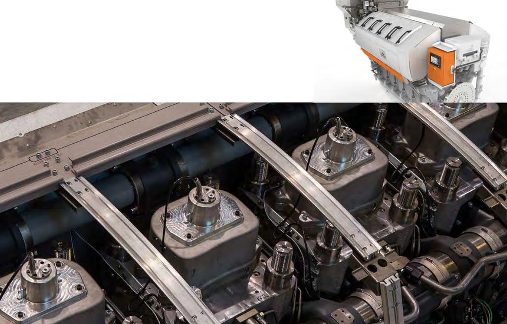
51 Wärtsilä 31 Product Guide 4. Description of the Engine 4. Description of the Engine 4.1 Definitions Fig 4-1 Engine definitions (V93C0028) 4.2 Main components and systems Engine block Crankshaft The engine block, made of nodular cast iron, is cast in one piece for all cylinder numbers and it supports the underslung crankshaft. The block has been given a stiff and durable design to absorb internal forces and the engine can therefore also be resiliently mounted not requiring any intermediate foundations. It incorporates water and charge air main and side channels. Also camshaft bearing housings are incorporated in the engine block. The engines are equipped with crankcase explosion relief valve with flame arrester. The main bearing caps, made of nodular cast iron, are fixed with two hydraulically tensioned screws from below. They are guided sideways and vertically by the engine block. Hydraulically tensioned horizontal side screws at the lower guiding provide a very rigid crankshaft bearing assembly. A hydraulic jack, supported in the oil sump, offers the possibility to lower and lift the main bearing caps, e.g. when inspecting the bearings. Lubricating oil is led to the bearings through this jack. The oil sump, a light welded design, is mounted on the engine block from below. The oil sump is available in two alternative designs, wet or dry sump, depending on the type of application. The wet oil sump includes a suction pipe to the lubricating oil pump. For wet sump there is a main distributing pipe for lubricating oil, suction pipes and return connections for the separator. For the dry sump there is a main distributing oil pipe for lubricating oil and drains at either end to a separate system oil tank. The engine holding down bolts are hydraulically tightened in order to facilitate the engine installation to both rigid and resilient foundation. Crankshaft line is built up from several pieces: crankshaft, counter weights, split camshaft gear wheel and pumpdrive arrangement. Wärtsilä 31 Product Guide - a5-7 June
52 4. Description of the Engine Wärtsilä 31 Product Guide Crankshaft itself is forged in one piece. Both main bearings and big end bearings temperatures are continuously monitored. Counterweights are fitted on every web. High degree of balancing results in an even and thick oil film for all bearings. The connecting rods are arranged side-by-side and the diameters of the crank pins and journals are equal irrespective of the cylinder number. All crankshafts can be provided with torsional vibration dampers or tuning masses at the free end of the engine, if necessary. Main features of crankshaft design: clean steel technology minimizes the amount of slag forming elements and guarantees superior material durability. The crankshaft alignment is always done on a thoroughly warm engine after the engine is stopped Connecting rod The connecting rod is of forged alloy steel. All connecting rod studs are hydraulically tightened. The connecting rod is of a three-piece design, which gives a minimum dismantling height and enables the piston to be dismounted without opening the big end bearing Main bearings and big end bearings The main bearings and the big end bearings are of tri-metal design with steel back, lead-bronze lining and a soft running layer. The bearings are covered with a Sn-flash for corrosion protection. Even minor form deviations can become visible on the bearing surface in the running in phase. This has no negative influence on the bearing function. A wireless system for real-time temperature monitoring of connecting rod big end bearings, "BEB monitoring system", is as standard Cylinder liner Piston The cylinder liners are centrifugally cast of a special alloyed cast iron. The top collar of the cylinder liner is provided with a water jacket for distributing cooling water through the cylinder liner cooling bores. This will give an efficient control of the liner temperature. An oil lubrication system inside the cylinder liner lubricates the gudgeon pin bearing and also cools piston crown through the oil channels underside of the piston. The piston is of composite type with steel crown and nodular cast iron skirt. A piston skirt lubricating system, featuring oil bores in a groove on the piston skirt, lubricates the piston skirt/cylinder liner. The piston top is oil cooled by the same system mentioned above. The piston ring grooves are hardened for extended lifetime Piston rings The piston ring set are located in the piston crown and consists of two directional compression rings and one spring-loaded conformable oil scraper ring. Running face of compression rings are chromium-ceramic-plated Cylinder head The cross flow cylinder head is made of cast iron. The mechanical load is absorbed by a flame plate, which together with the upper deck and the side walls form a rigid box section. There are four hydraulically tightened cylinder head bolts. The exhaust valve seats and the flame deck are efficiently and direct water-cooled. The valve seat rings are made of alloyed steel, for wear resistance. All valves are hydraulic controlled with valve guides and equipped with valve springs and rotators. 4-2 Wärtsilä 31 Product Guide - a5-7 June 2018
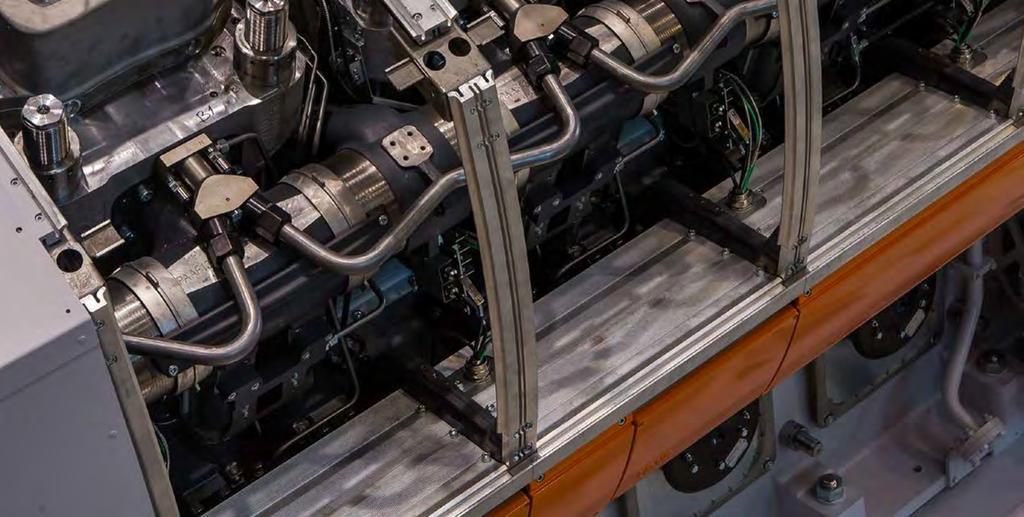
53 Wärtsilä 31 Product Guide 4. Description of the Engine A small side air receiver is located in the hot box, including charge air bends with integrated hydraulics and charge air riser pipes. Following components are connected to the cylinder head: Charge air components for side receiver Exhaust gas pipe to exhaust system Cooling water collar Quill pipe with High Pressure (HP) fuel pipe connections Camshaft and valve mechanism The cams are integrated in the drop forged shaft material. The bearing journals are made in separate pieces, which are fitted, to the camshaft pieces by flange connections. The camshaft bearing housings are integrated in the engine block casting and are thus completely closed. The bearings are installed and removed by means of a hydraulic tool. The camshaft covers, one for each cylinder, seal against the engine block with a closed O-ring profile. The valve tappets are of piston type with self-adjustment of roller against cam to give an even distribution of the contact pressure. Inlet and exhaust valves have a special steam coating and hard facing on the seat surface, for long lifetime. The valve springs make the valve mechanism dynamically stable. The step-less valve mechanism makes it possible to control the timing of both inlet & exhaust valves. It allows to always use a proper scavenging period. This is needed to optimize and balance emissions, fuel consumption, operational flexibility & load taking, whilst maintaining thermal and mechanical reliability. The design enables clearly longer maintenance interval, due to the reduced thermal and mechanical stress on most of the components in the valve mechanism Camshaft drive The camshafts are driven by the crankshaft through a gear train Turbocharging and charge air cooling The selected 2-stage turbocharging offers ideal combination of high-pressure ratios and good efficiency both at full and part load. The turbochargers can be placed at the free end or fly wheel end of the engine. For cleaning of the turbochargers during operation there is, as standard, a water washing device for the air (compressor) and exhaust gas (turbine) side of the LP stage and for the exhaust gas (turbine) side of the HP stage. The water washing device is to be connected to an external unit. The turbochargers are lubricated by engine lubricating oil with integrated connections. An Exhaust gas Waste Gate (EWG) system controls the exhaust gas flow by-passing for both high pressure (HP) and low pressure (LP) turbine stages. EWG is needed also in case of engines equipped with exhaust gas after treatment based on Selective Catalytic Reaction (SCR). By using Air Waste Gate (AWG) the charge air pressure and the margin from LP compressor is controlled. A step-less Air By-pass valve (ABP) system is used in all engine applications for preventing surging of turbocharger compressors in case of rapid engine load reduction. The Charge Air Coolers (CAC) consist of a 2-stage type cooler (LP CAC) between the LP and HP compressor stages and a 1-stage cooler (HP CAC) between the HP compressor stage and the charge air receiver. The LP CAC is cooled with LT-water or in some cases by both HT- and LT-water. The HP CAC is always cooled by LT-water and fresh water is used for both circuits. When there is a risk for over-speeding of the engine due to presence of combustible gas or vapour in the inlet air, a UNIC automation controlled Charge Air Blocking device, can be installed. See chapter Exhaust gas & charge air systems for more information. Wärtsilä 31 Product Guide - a5-7 June
54 4. Description of the Engine Wärtsilä 31 Product Guide Fuel injection equipment The fuel injection equipment and system piping are located in a hotbox, providing maximum reliability and safety when using preheated heavy fuels. In the Wärtsilä electronic fuel injection system, the fuel is pressurized in the high pressure HP-pumps from where the fuel is fed to the injection valves which are rate optimized. The fuel system consists of different numbers of fuel oil HP pumps, depending of the cylinder configuration. HP pumps are located at the engine pump cover and from there high pressure pipes are connected to the system piping. A valve block is mounted at the fuel outlet pipe, including Pressure Drop and Safety Valve (PDSV), Circulation Valve (CV) and a fuel pressure discharge volume. The PDSV acts as mechanical safety valve and the fuel volume lowers the system pressure. The injection valves are electronic controlled and the injection timing is pre-set in the control system software Lubricating oil system The engine internal lubricating oil system include the engine driven lubricating oil pump, the electrically driven prelubricating oil pump, thermostatic valve, filters and lubricating oil cooler. The lubricating oil pumps are located in the free end of the engine, while the automatic filter, cooler and thermostatic valve are integrated into one module Cooling water system The fresh water cooling system is divided into a high temperature (HT) and a low temperature (LT) circuit. For engines operating in normal conditions the HT-water is cooling the cylinders (jacket) and the first stage of the low pressure 2-stage charge air cooler. The LT-water is cooling the lubricating oil cooler, the second stage of the low pressure 2-stage charge air cooler and the high pressure 1-stage charge air cooler. For engines operating in cold conditions the HT-water is cooling the cylinders (Jacket). A HT-water pump is circulating the cooling water in the circuit and a thermostatic valve mounted in the internal cooling water system, controls the outlet temperature of the circuit. The LT-circuit is cooling the Lubricating Oil Cooler (LOC), the second stage of the Low Pressure 2-stage charge air cooler, the High Pressure 1-stage charge air cooler and the first stage of the low pressure 2-stage charge air cooler. An LT-thermostatic valve mounted in the external cooling water system, controls the inlet temperature to the engine for achieving correct receiver temperature Exhaust pipes The exhaust manifold pipes are made of special heat resistant nodular cast iron alloy. The complete exhaust gas system is enclosed in an insulating box consisting of easily removable panels. Mineral wool is used as insulating material Automation system The Wärtsilä 31 engine is equipped with an UNIC electronic control system. UNIC have hardwired interface for control functions and a bus communication interface for alarm and monitoring. Additionally UNIC includes fuel injection control for engines with electronic fuel injection rate optimized nozzles. For more information, see chapter Automation system. 4-4 Wärtsilä 31 Product Guide - a5-7 June 2018
55 Wärtsilä 31 Product Guide 4. Description of the Engine 4.3 Expected overhaul intervals and life times Time between inspection or Overhaul & Expected Life Time NOTE Time Between Overhaul data can be found in Services Engine Operation and Maintenance Manual (O&MM) Expected lifetime values may differ from values found in Services O&MM manual Achieved life times very much depend on the operating conditions, average loading of the engine, fuel quality used, fuel handling systems, performance of maintenance etc Expected lifetime is different depending on HFO1 or HFO2 used. For detailed information of HFO1 and HFO2 qualities, please see Lower value in life time range is for engine load more than 75%. Higher value is for loads less than 75% Table 4-1 Time Between Overhaul and Expected Life Time Component Time between inspection or overhaul (h) Expected life time (h) HFO operation LFO HFO operation LFO Piston Min Min Piston rings Cylinder liner Cylinder head Inlet valve Exhaust valve Main bearing Big end bearing Intermediate gear bearings Balancing shaft bearings Injection valve (wear parts) NA NA High Pressure fuel pump LP and the HP turbochargers Engine storage At delivery the engine is provided with VCI coating and a tarpaulin. For storage longer than 3 months please contact Wärtsilä Finland Oy. Wärtsilä 31 Product Guide - a5-7 June
56 This page intentionally left blank
57 Wärtsilä 31 Product Guide 5. Piping Design, Treatment and Installation 5. Piping Design, Treatment and Installation This chapter provides general guidelines for the design, construction and planning of piping systems, however, not excluding other solutions of at least equal standard. Installation related instructions are included in the project specific instructions delivered for each installation. Fuel, lubricating oil, fresh water and compressed air piping is usually made in seamless carbon steel (DIN 2448) and seamless precision tubes in carbon or stainless steel (DIN 2391), exhaust gas piping in welded pipes of corten or carbon steel (DIN 28). Sea-water piping should be in Cunifer or hot dip galvanized steel. NOTE The pipes in the freshwater side of the cooling water system must not be galvanized! Attention must be paid to fire risk aspects. Fuel supply and return lines shall be designed so that they can be fitted without tension. Flexible hoses must have an approval from the classification society. If flexible hoses are used in the compressed air system, a purge valve shall be fitted in front of the hose(s). It is recommended to make a fitting order plan prior to construction. The following aspects shall be taken into consideration: Pockets shall be avoided. When not possible, drain plugs and air vents shall be installed Leak fuel drain pipes shall have continuous slope Vent pipes shall be continuously rising Flanged connections shall be used, cutting ring joints for precision tubes Maintenance access and dismounting space of valves, coolers and other devices shall be taken into consideration. Flange connections and other joints shall be located so that dismounting of the equipment can be made with reasonable effort. 5.1 Pipe dimensions When selecting the pipe dimensions, take into account: The pipe material and its resistance to corrosion/erosion. Allowed pressure loss in the circuit vs delivery head of the pump. Required net positive suction head (NPSH) for pumps (suction lines). In small pipe sizes the max acceptable velocity is usually somewhat lower than in large pipes of equal length. The flow velocity should not be below 1 m/s in sea water piping due to increased risk of fouling and pitting. In open circuits the velocity in the suction pipe is typically about 2/3 of the velocity in the delivery pipe. Wärtsilä 31 Product Guide - a5-7 June
58 5. Piping Design, Treatment and Installation Wärtsilä 31 Product Guide Table 5-1 Recommended maximum velocities on pump delivery side for guidance Piping Fuel oil piping (MDF and HFO) Lubricating oil piping Fresh water piping Sea water piping Pipe material Black steel Black steel Black steel Galvanized steel Aluminum brass 10/90 copper-nickel-iron 70/30 copper-nickel Rubber lined pipes Max velocity [m/s] NOTE The diameter of gas fuel piping depends only on the allowed pressure loss in the piping, which has to be calculated project specifically. Compressed air pipe sizing has to be calculated project specifically. The pipe sizes may be chosen on the basis of air velocity or pressure drop. In each pipeline case it is advised to check the pipe sizes using both methods, this to ensure that the alternative limits are not being exceeded. Pipeline sizing on air velocity: For dry air, practical experience shows that reasonable velocities are m/s, but these should be regarded as the maximum above which noise and erosion will take place, particularly if air is not dry. Even these velocities can be high in terms of their effect on pressure drop. In longer supply lines, it is often necessary to restrict velocities to 15 m/s to limit the pressure drop. Pipeline sizing on pressure drop: As a rule of thumb the pressure drop from the starting air vessel to the inlet of the engine should be max. 0.1 MPa (1 bar) when the bottle pressure is 3 MPa (30 bar). It is essential that the instrument air pressure, feeding to some critical control instrumentation, is not allowed to fall below the nominal pressure stated in chapter "Compressed air system" due to pressure drop in the pipeline. 5.2 Trace heating The following pipes shall be equipped with trace heating (steam, thermal oil or electrical). It shall be possible to shut off the trace heating. All heavy fuel pipes All leak fuel and filter flushing pipes carrying heavy fuel 5.3 Pressure class The pressure class of the piping should be higher than or equal to the design pressure, which should be higher than or equal to the highest operating (working) pressure. The highest operating (working) pressure is equal to the setting of the safety valve in a system. The pressure in the system can: Originate from a positive displacement pump 5-2 Wärtsilä 31 Product Guide - a5-7 June 2018
59 Wärtsilä 31 Product Guide 5. Piping Design, Treatment and Installation Be a combination of the static pressure and the pressure on the highest point of the pump curve for a centrifugal pump Rise in an isolated system if the liquid is heated Within this publication there are tables attached to drawings, which specify pressure classes of connections. The pressure class of a connection can be higher than the pressure class required for the pipe. Example 1: The fuel pressure before the engine should be 0.7 MPa (7 bar). The safety filter in dirty condition may cause a pressure loss of 0.1 MPa (1.0 bar). The viscosimeter, automatic filter, preheater and piping may cause a pressure loss of 0.25 MPa (2.5 bar). Consequently the discharge pressure of the circulating pumps may rise to 1.05 MPa (10.5 bar), and the safety valve of the pump shall thus be adjusted e.g. to 1.2 MPa (12 bar). A design pressure of not less than 1.2 MPa (12 bar) has to be selected. The nearest pipe class to be selected is PN16. Piping test pressure is normally 1.5 x the design pressure = 1.8 MPa (18 bar). Example 2: 5.4 Pipe class The pressure on the suction side of the cooling water pump is 0.1 MPa (1 bar). The delivery head of the pump is 0.3 MPa (3 bar), leading to a discharge pressure of 0.4 MPa (4 bar). The highest point of the pump curve (at or near zero flow) is 0.1 MPa (1 bar) higher than the nominal point, and consequently the discharge pressure may rise to 0.5 MPa (5 bar) (with closed or throttled valves). Consequently a design pressure of not less than 0.5 MPa (5 bar) shall be selected. The nearest pipe class to be selected is PN6. Piping test pressure is normally 1.5 x the design pressure = 0.75 MPa (7.5 bar). Standard pressure classes are PN4, PN6, PN10, PN16, PN25, PN40, etc. Classification societies categorize piping systems in different classes (DNV) or groups (ABS) depending on pressure, temperature and media. The pipe class can determine: Type of connections to be used Heat treatment Welding procedure Test method Systems with high design pressures and temperatures and hazardous media belong to class I (or group I), others to II or III as applicable. Quality requirements are highest on class I. Examples of classes of piping systems as per DNV rules are presented in the table below. Table 5-2 Classes of piping systems as per DNV rules Media Class I Class II Class III MPa (bar) MPa (bar) MPa (bar) Steam > 1.6 (16) or > 300 < 1.6 (16) and < 300 < 0.7 (7) and < 170 Flammable fluid > 1.6 (16) or > 150 < 1.6 (16) and < 150 < 0.7 (7) and < 60 Other media > 4 (40) or > 300 < 4 (40) and < 300 < 1.6 (16) and < 200 Wärtsilä 31 Product Guide - a5-7 June
60 5. Piping Design, Treatment and Installation Wärtsilä 31 Product Guide 5.5 Insulation The following pipes shall be insulated: All trace heated pipes Exhaust gas pipes Exposed parts of pipes with temperature > 60 Insulation is also recommended for: Pipes between engine or system oil tank and lubricating oil separator Pipes between engine and jacket water preheater 5.6 Local gauges Local thermometers should be installed wherever a new temperature occurs, i.e. before and after heat exchangers, etc. Pressure gauges should be installed on the suction and discharge side of each pump. 5.7 Cleaning procedures Instructions shall be given at an early stage to manufacturers and fitters how different piping systems shall be treated, cleaned and protected Cleanliness during pipe installation All piping must be verified to be clean before lifting it onboard for installation. During the construction time uncompleted piping systems shall be maintained clean. Open pipe ends should be temporarily closed. Possible debris shall be removed with a suitable method. All tanks must be inspected and found clean before filling up with fuel, oil or water. Piping cleaning methods are summarised in table below: Table 5-3 Pipe cleaning System Fuel oil Lubricating oil Starting air Cooling water Exhaust gas Charge air Methods A,B,C,D,F A,B,C,D,F A,B,C A,B,C A,B,C A,B,C 1) In case of carbon steel pipes Methods applied during prefabrication of pipe spools A = Washing with alkaline solution in hot water at 80 for degreasing (only if pipes have been greased) B = Removal of rust and scale with steel brush (not required for seamless precision tubes) D = Pickling (not required for seamless precision tubes) Methods applied after installation onboard 5-4 Wärtsilä 31 Product Guide - a5-7 June 2018
61 Wärtsilä 31 Product Guide 5. Piping Design, Treatment and Installation C = Purging with compressed air F = Flushing Pickling Prefabricated pipe spools are pickled before installation onboard. Pipes are pickled in an acid solution of 10% hydrochloric acid and 10% formaline inhibitor for 4-5 hours, rinsed with hot water and blown dry with compressed air. After acid treatment the pipes are treated with a neutralizing solution of 10% caustic soda and 50 grams of trisodiumphosphate per litre of water for 20 minutes at , rinsed with hot water and blown dry with compressed air. Great cleanliness shall be approved in all work phases after completed pickling. 5.8 Flexible pipe connections Pressurized flexible connections carrying flammable fluids or compressed air have to be type approved. Great care must be taken to ensure proper installation of flexible pipe connections between resiliently mounted engines and ship s piping. Flexible pipe connections must not be twisted Installation length of flexible pipe connections must be correct Minimum bending radius must be respected Piping must be concentrically aligned When specified the flow direction must be observed Mating flanges shall be clean from rust, burrs and anticorrosion coatings Bolts are to be tightened crosswise in several stages Flexible elements must not be painted Rubber bellows must be kept clean from oil and fuel The piping must be rigidly supported close to the flexible piping connections. Wärtsilä 31 Product Guide - a5-7 June
62 5. Piping Design, Treatment and Installation Wärtsilä 31 Product Guide Fig 5-1 Flexible hoses 5.9 Clamping of pipes It is very important to fix the pipes to rigid structures next to flexible pipe connections in order to prevent damage caused by vibration. The following guidelines should be applied: Pipe clamps and supports next to the engine must be very rigid and welded to the steel structure of the foundation. The first support should be located as close as possible to the flexible connection. Next support should be m from the first support. First three supports closest to the engine or generating set should be fixed supports. Where necessary, sliding supports can be used after these three fixed supports to allow thermal expansion of the pipe. Supports should never be welded directly to the pipe. Either pipe clamps or flange supports should be used for flexible connection. Examples of flange support structures are shown in Figure 5-2. A typical pipe clamp for a fixed support is shown in Figure 5-3. Pipe clamps must be made of steel; plastic clamps or similar may not be used. 5-6 Wärtsilä 31 Product Guide - a5-7 June 2018
63 Wärtsilä 31 Product Guide 5. Piping Design, Treatment and Installation Fig 5-2 Flange supports of flexible pipe connections (4V60L0796) Fig 5-3 Pipe clamp for fixed support (4V61H0842) Wärtsilä 31 Product Guide - a5-7 June
64 This page intentionally left blank
65 Wärtsilä 31 Product Guide 6. Fuel Oil System 6. Fuel Oil System 6.1 Acceptable fuel characteristics The fuel specifications are based on the ISO 8217:2017 (E) standard. Observe that a few additional properties not included in the standard are listed in the tables. For maximum fuel temperature before the engine, see chapter "Technical Data". The fuel shall not contain any added substances or chemical waste, which jeopardizes the safety of installations or adversely affects the performance of the engines or is harmful to personnel or contributes overall to air pollution Marine Diesel Fuel (MDF) Distillate fuel grades are ISO-F-DMX, DMA, DMZ, DMB. These fuel grades are referred to as MDF (Marine Diesel Fuel). The distillate grades mentioned above can be described as follows: DMX: A fuel which is suitable for use at ambient temperatures down to -15 without heating the fuel. Especially in merchant marine applications its use is restricted to lifeboat engines and certain emergency equipment due to the reduced flash point. The low flash point which is not meeting the SOLAS requirement can also prevent the use in other marine applications, unless the fuel system is built according to special requirements. Also the low viscosity (min. 1.4 cst) can prevent the use in engines unless the fuel can be cooled down enough to meet the min. injection viscosity limit of the engine. DMA: A high quality distillate, generally designated as MGO (Marine Gas Oil). DMZ: A high quality distillate, generally designated as MGO (Marine Gas Oil). An alternative fuel grade for engines requiring a higher fuel viscosity than specified for DMA grade fuel. DMB: A general purpose fuel which may contain trace amounts of residual fuel and is intended for engines not specifically designed to burn residual fuels. It is generally designated as MDO (Marine Diesel Oil) Table Light fuel oils Table 6-1 Distillate fuel specifications Characteristics Unit Test method(s) and references Limit DMX Category ISO-F DMA DFA DMZ DFZ DMB DFB Max 5,500 6,000 6,000 11,00 Kinematic viscosity at 40 j) mm 2 /s a) Min 1,400 i) 2,000 3,000 2,000 ISO 3104 Density at 15 kg/m³ Max - 890,0 890,0 900,0 ISO 3675 or ISO Cetane index Min ISO 4264 Sulphur b, k) % m/m Max 1,00 1,00 1,00 1,50 ISO 8754 or ISO 196, ASTM D4294 Flash point Min 43,0 l) 60,0 60,0 60,0 ISO 2719 Hydrogen sulfide mg/kg Max 2,00 2,00 2,00 2,00 IP 570 Wärtsilä 31 Product Guide - a5-7 June
66 6. Fuel Oil System Wärtsilä 31 Product Guide Characteristics Unit Test method(s) and references Limit DMX Category ISO-F DMA DFA DMZ DFZ DMB DFB Acid number mg KOH/g Max 0,5 0,5 0,5 0,5 ASTM D664 Total sediment by hot filtration % m/m Max ,10 c) ISO Oxidation stability g/m³ Max d) ISO Fatty acid methyl ester (FAME) e) % v/v Max - - 7,0-7,0-7,0 ASTM D7963 or IP 579 Carbon residue Micro method on 10% distillation residue % m/m Max 0,30 0,30 0,30 - ISO Carbon residue Micro method % m/m Max ,30 ISO winter -16 Report Report - Cloud point f) Max summer ISO 3015 Cold filter plugging point f) winter summer Max - - Report - Report IP 309 or IP 612 winter Pour point f) Max summer ISO 3016 Appearance - Clear and bright g) c) - Water % v/v Max ,30 c) ISO 3733 Ash % m/m Max 0,010 0,010 0,010 0,010 ISO 62 Lubricity, corr. wear scar diam. h) µm Max d) ISO Wärtsilä 31 Product Guide - a5-7 June 2018
67 Wärtsilä 31 Product Guide 6. Fuel Oil System a) 1 mm²/s = 1 cst. NOTE b) Notwithstanding the limits given, the purchaser shall define the maximum sulphur content in accordance with relevant statutory limitations. c) If the sample is not clear and bright, the total sediment by hot filtration and water tests shall be required. d) If the sample is not clear and bright, the Oxidation stability and Lubricity tests cannot be undertaken and therefore, compliance with this limit cannot be shown. e) See ISO 8217:2017(E) standard for details. f) Pour point cannot guarantee operability for all ships in all climates. The purchaser should confirm that the cold flow characteristics (pour point, cloud point, cold filter clogging point) are suitable for ship s design and intended voyage. g) If the sample is dyed and not transparent, see ISO 8217:2017(E) standard for details related to water analysis limits and test methods. h) The requirement is applicable to fuels with a sulphur content below 500 mg/kg (0,050 % m/m). Additional notes not included in the ISO 8217:2017(E) standard: i) Low min. viscosity of 1,400 mm²/s can prevent the use ISO-F-DMX category fuels in Wärtsilä 4-stroke engines unless a fuel can be cooled down enough to meet the specified min. injection viscosity limit. k) There doesn t exist any minimum sulphur content limit for Wärtsilä 4-stroke diesel engines and also the use of Ultra Low Sulphur Diesel (ULSD) is allowed provided that the fuel quality fulfils other specified properties. l) Low flash point of min. 43 can prevent the use ISO-F-DMX category fuels in Wärtsilä engines in marine applications unless the ship s fuel system is built according to special requirements allowing the use or that the fuel supplier is able to guarantee that flash point of the delivered fuel batch is above 60 being a requirement of SOLAS and classification societies. Wärtsilä 31 Product Guide - a5-7 June
68 6. Fuel Oil System Wärtsilä 31 Product Guide ,10% m/m sulphur fuels for SECA areas Due to the tightened sulphur emission legislation being valid since in the specified SECA areas many new max. 0,10 % m/m sulphur content fuels have entered the market. Some of these fuels are not pure distillate fuels, but contain new refinery streams, like hydrocracker bottoms or can also be blends of distillate and residual fuels. The new 0,10 % m/m sulphur fuels are also called as Ultra Low Sulphur Fuel Oils (ULSFO) or hybrid fuels, since those can contain properties of both distillate and residual fuels. In the existing ISO 8217:2017(E) standard the fuels are classed as RMA 10, RMB 30 or RMD 80, if not fulling the DM grade category requirements, though from their properties point of view this is generally not an optimum approach. These fuels can be used in the Wärtsilä 31 engine type, but special attention shall be paid to optimum operating conditions. See also Services Instruction WS02Q312. Characteristics Unit RMA 10 RMB 30 RMD 80 Test method reference Kinematic viscosity bef. inj. pumps c) mm 2 /s a) 6,0-24 6,0-24 6, Kinematic viscosity at 50, max. mm 2 /s a) 10,00 30,00 80,00 ISO 3104 Density at 15, max. kg/m 3 920,0 960,0 975,0 ISO 3675 or ISO CCAI, max. e) ISO 8217, Annex F Sulphur, max. b), f) % m/m 0,10 0,10 0,10 ISO 8574 or ISO 196 Flash point, min. 60,0 60,0 60,0 ISO 2719 Hydrogen sulfide, max. mg/kg 2,00 2,00 2,00 IP 570 Acid number, max. mg KOH/g 2,5 2,5 2,5 ASTM D664 Total sediment existent, max. % m/m 0,10 0,10 0,10 ISO Carbon residue, micro method, max. % m/m 2,50 10,00 14,00 ISO Asphaltenes, max. c) % m/m 1,5 6,0 8,0 ASTM D3279 Pour point (upper), max., winter quality d) ISO 3016 Pour point (upper), max., summer quality d) ISO 3016 Water max. % v/v 0,30 0,50 0,50 ISO 3733 or ASTM D6304-C c) Water bef. engine, max. c) % v/v 0,30 0,30 0,30 ISO 3733 or ASTM D6304-C c) Ash, max. % m/m 0,040 0,070 0,070 ISO 62 or LP1 c, h) Vanadium, max. f) mg/kg IP 501, IP 470 or ISO 197 Sodium, max. f) mg/kg 50 IP 501 or IP 470 Sodium bef. engine, max. c, f) mg/kg IP 501 or IP Wärtsilä 31 Product Guide - a5-7 June 2018
69 Wärtsilä 31 Product Guide 6. Fuel Oil System Characteristics Unit RMA 10 RMB 30 RMD 80 Test method reference Aluminium + Silicon, max. mg/kg IP 501, IP 470 or ISO Aluminium + Silicon bef. engine, max. c) mg/kg IP 501, IP 470 or ISO Used lubricating oil: g) - Calcium, max. - Zinc, max. - Phosphorus, max. mg/kg mg/kg mg/kg IP 501 or IP 470 IP 501 or IP 470 IP 501 or IP 500 a) 1 mm²/s = 1 cst. NOTE b) The purchaser shall define the maximum sulphur content in accordance with relevant statutory limitations. c) Additional properties specified by the engine manufacturer, which are not included in the ISO 8217:2017(E) standard. d) Purchasers shall ensure that this pour point is suitable for the equipment on board / at the plant, especially if the ship operates / plant is located in cold climates. e) Straight run residues show CCAI values in the 770 to 840 range and are very good ignitors. Cracked residues delivered as bunkers may range from 840 to in exceptional cases above 900. Most bunkers remain in the max. 850 to 870 range at the moment. CCAI value cannot always be considered as an accurate tool to determine fuels ignition properties, especially concerning fuels originating from modern and more complex refinery processes. f) Sodium contributes to hot corrosion on exhaust valves when combined with high sulphur and vanadium contents. Sodium also strongly contributes to fouling of the exhaust gas turbine blading at high loads. The aggressiveness of the fuel depends on its proportions of sodium and vanadium, but also on the total amount of ash. Hot corrosion and deposit formation are, however, also influenced by other ash constituents. It is therefore difficult to set strict limits based only on the sodium and vanadium content of the fuel. Also a fuel with lower sodium and vanadium contents than specified above, can cause hot corrosion on engine components. g) The fuel shall be free from used lubricating oil (ULO). A fuel shall be considered to contain ULO when either one of the following conditions is met: Calcium > 30 mg/kg and zinc > 15 mg/kg OR Calcium > 30 mg/kg and phosphorus > 15 mg/kg h) Ashing temperatures can vary when different test methods are used having an influence on the test result. Wärtsilä 31 Product Guide - a5-7 June
70 6. Fuel Oil System Wärtsilä 31 Product Guide Heavy Fuel Oil (HFO) Residual fuel grades are referred to as HFO (Heavy Fuel Oil). The fuel specification HFO 2 covers the categories ISO-F-RMA 10 to RMK 700. Fuels fulfilling the specification HFO 1 permit longer overhaul intervals of specific engine components than HFO Table Heavy fuel oils Table 6-2 Residual fuel specifications Characteristics Unit Limit HFO 1 Limit HFO 2 Test method reference Kinematic viscosity bef. inj. pumps d) mm 2 /s b) 20 ± 4 20 ± 4 - Kinematic viscosity at 50, max. mm 2 /s b) 700,0 700,0 ISO 3104 Density at 15, max. kg/m 3 991,0 / 1010,0 a) 991,0 / 1010,0 a) ISO 3675 or ISO CCAI, max. f) ISO 8217, Annex F Sulphur, max. c, g) %m/m Statutory requirements ISO 8754 or ISO 196 Flash point, min. 60,0 60,0 ISO 2719 Hydrogen sulfide, max. mg/kg 2,00 2,00 IP 570 Acid number, max. mg KOH/g 2,5 2,5 ASTM D664 Total sediment aged, max. %m/m 0,10 0,10 ISO Carbon residue, micro method, max. %m/m 15,00 20,00 ISO Asphaltenes, max. d) %m/m 8,0 14,0 ASTM D3279 Pour point (upper), max. e) ISO 3016 Water, max. d) %V/V 0,50 0,50 ISO 3733 or ASTM D6304-C d) Water before engine, max. d) %V/V 0,30 0,30 ISO 3733 or ASTM D6304-C d) Ash, max. %m/m 0,050 0,150 ISO 62 or LP1 d, i) Vanadium, max. g) mg/kg 0 IP 501, IP 470 or ISO 197 Sodium, max. g) mg/kg 50 IP 501 or IP 470 Sodium before engine, max. d, g) mg/kg IP 501 or IP 470 Aluminium + Silicon, max. d) mg/kg IP 501, IP 470 or ISO Aluminium + Silicon before engine, max. d) mg/kg IP 501, IP 470 or ISO Used lubricating oil h) - Calcium, max. - Zinc, max. - Phosphorus, max. mg/kg mg/kg mg/kg IP 501 or IP 470 IP 501 or IP 470 IP 501 or IP Wärtsilä 31 Product Guide - a5-7 June 2018
71 Wärtsilä 31 Product Guide 6. Fuel Oil System NOTE a) Max kg/m³ at 15, provided the fuel treatment system can reduce water and solids (sediment, sodium, aluminium, silicon) before engine to the specified levels. b) 1 mm²/s = 1 cst. c) The purchaser shall define the maximum sulphur content in accordance with relevant statutory limitations. d) Additional properties specified by the engine manufacturer, which are not included in the ISO 8217:2017(E) standard. e) Purchasers shall ensure that this pour point is suitable for the equipment on board / at the plant, especially if the ship operates / plant is located in cold climates. f) Straight run residues show CCAI values in the 770 to 840 range and are very good ignitors. Cracked residues delivered as bunkers may range from 840 to in exceptional cases above 900. Most bunkers remain in the max. 850 to 870 range at the moment. CCAI value cannot always be considered as an accurate tool to determine fuels ignition properties, especially concerning fuels originating from modern and more complex refinery processes. g) Sodium contributes to hot corrosion on exhaust valves when combined with high sulphur and vanadium contents. Sodium also strongly contributes to fouling of the exhaust gas turbine blading at high loads. The aggressiveness of the fuel depends on its proportions of sodium and vanadium, but also on the total amount of ash. Hot corrosion and deposit formation are, however, also influenced by other ash constituents. It is therefore difficult to set strict limits based only on the sodium and vanadium content of the fuel. Also a fuel with lower sodium and vanadium contents than specified above, can cause hot corrosion on engine components. h) The fuel shall be free from used lubricating oil (ULO). A fuel shall be considered to contain ULO when either one of the following conditions is met: Calcium > 30 mg/kg and zinc > 15 mg/kg OR Calcium > 30 mg/kg and phosphorus > 15 mg/kg i) The ashing temperatures can vary when different test methods are used having an influence on the test result. Wärtsilä 31 Product Guide - a5-7 June
72 6. Fuel Oil System Wärtsilä 31 Product Guide NOTE b) if not within the given limits, the maximum sulphur content to be defined in accordance with relevant statutory limitations. c) It shall be ensured that the pour point is suitable for the equipment on board, especially if the ship operates in cold climates. d) If the sample is not clear and bright, the total sediment by hot filtration and water tests shall be required. e) If the sample is not clear and bright, the test cannot be undertaken and hence the oxidation stability limit shall not apply. f) If the sample is not clear and bright, the test cannot be undertaken and hence the lubricity limit shall not apply. g) The requirement is applicable to fuels with a sulphur content below 500 mg/kg (50 % mass). h) Additional properties specified by Wärtsilä, which are not included in the ISO specification. i) If the sample is dyed and not transparent, then the water limit and test method ISO shall apply. 6.2 External fuel oil system The design of the external fuel system may vary from ship to ship, but every system should provide well cleaned fuel of correct viscosity and pressure to each engine. Temperature control is required to maintain stable and correct viscosity of the fuel before the injection pumps (see Technical data). Sufficient circulation through every engine connected to the same circuit must be ensured in all operating conditions. The fuel treatment system should comprise at least one settling tank and two separators. Correct dimensioning of HFO separators is of greatest importance, and therefore the recommendations of the separator manufacturer must be closely followed. Poorly centrifuged fuel is harmful to the engine and a high content of water may also damage the fuel feed system. The fuel pipes between the feed unit and the engine must be properly clamped to rigid structures. The distance between the fixing points should be at close distance next to the engine. See chapter Piping design, treatment and installation. A connection for compressed air should be provided before the engine, together with a drain from the fuel return line to the clean leakage fuel or overflow tank. With this arrangement it is possible to blow out fuel from the engine prior to maintenance work, to avoid spilling. NOTE In multiple engine installations, where several engines are connected to the same fuel feed circuit, it must be possible to close the fuel supply and return lines connected to the engine individually. This is a SOLAS requirement. It is further stipulated that the means of isolation shall not affect the operation of the other engines, and it shall be possible to close the fuel lines from a position that is not rendered inaccessible due to fire on any of the engines Fuel heating requirements HFO Heating is required for: Bunker tanks, settling tanks, day tanks Pipes (trace heating) Separators 6-8 Wärtsilä 31 Product Guide - a5-7 June 2018
73 Wärtsilä 31 Product Guide 6. Fuel Oil System Fuel feeder/booster units To enable pumping the temperature of bunker tanks must always be maintained above the pour point, typically at The heating coils can be designed for a temperature of 60. The tank heating capacity is determined by the heat loss from the bunker tank and the desired temperature increase rate. Fig 6-1 Fuel oil viscosity-temperature diagram for determining the pre-heating temperatures of fuel oils (4V92G0071b) Example 1: A fuel oil with a viscosity of 380 cst (A) at 50 (B) or 80 cst at 80 (C) must be pre-heated to (D-E) before the fuel high pressure pumps, to 98 (F) at the separator and to minimum 40 (G) in the bunker tanks. The fuel oil may not be pumpable below 36 (H). To obtain temperatures for intermediate viscosities, draw a line from the known viscosity/temperature point in parallel to the nearest viscosity/temperature line in the diagram. Example 2: Known viscosity 60 cst at 50 (K). The following can be read along the dotted line: viscosity at 80 = 20 cst, temperature at fuel high pressure pumps 74-87, separating temperature 86, minimum bunker tank temperature 28. Wärtsilä 31 Product Guide - a5-7 June
74 6. Fuel Oil System Wärtsilä 31 Product Guide Fuel tanks The fuel oil is first transferred from the bunker tanks to settling tanks for initial separation of sludge and water. After centrifuging the fuel oil is transferred to day tanks, from which fuel is supplied to the engines Settling tank, HFO (1T02) and MDF (1T10) Separate settling tanks for HFO and MDF are recommended. To ensure sufficient time for settling (water and sediment separation), the capacity of each tank should be sufficient for min. 24 hours operation at maximum fuel consumption. The tanks should be provided with internal baffles to achieve efficient settling and have a sloped bottom for proper draining. The temperature in HFO settling tanks should be maintained between 50 and 70, which requires heating coils and insulation of the tank. Usually MDF settling tanks do not need heating or insulation, but the tank temperature should be in the range Day tank, HFO (1T03) and MDF (1T06) Two day tanks for HFO are to be provided, each with a capacity sufficient for at least 8 hours operation at maximum fuel consumption. A separate tank is to be provided for MDF. The capacity of the MDF tank should ensure fuel supply for 8 hours. Settling tanks may not be used instead of day tanks. The day tank must be designed so that accumulation of sludge near the suction pipe is prevented and the bottom of the tank should be sloped to ensure efficient draining. HFO day tanks shall be provided with heating coils and insulation. It is recommended that the viscosity is kept below 140 cst in the day tanks. Due to risk of wax formation, fuels with a viscosity lower than 50 cst at 50 must be kept at a temperature higher than the viscosity would require. Continuous separation is nowadays common practice, which means that the HFO day tank temperature normally remains above 90. The temperature in the MDF day tank should be in the range The level of the tank must ensure a positive static pressure on the suction side of the fuel feed pumps Leak fuel tank, clean fuel (1T04) Clean leak fuel is drained by gravity from the engine. The fuel should be collected in a separate clean leak fuel tank, from where it can be pumped to the day tank and reused without separation. The pipes from the engine to the clean leak fuel tank should be arranged continuosly sloping. The tank and the pipes must be heated and insulated, unless the installation is designed for operation on MDF only. The leak fuel piping should be fully closed to prevent dirt from entering the system Leak fuel tank, dirty fuel (1T07) In normal operation no fuel should leak out from the components of the fuel system. In connection with maintenance, or due to unforeseen leaks, fuel or water may spill in the hot box of the engine. The spilled liquids are collected and drained by gravity from the engine through the dirty fuel connection. Dirty leak fuel shall be led to a sludge tank. The tank and the pipes must be heated and insulated, unless the installation is designed for operation exclusively on MDF Fuel treatment Separation Heavy fuel (residual, and mixtures of residuals and distillates) must be cleaned in an efficient centrifugal separator before it is transferred to the day tank Wärtsilä 31 Product Guide - a5-7 June 2018
75 Wärtsilä 31 Product Guide 6. Fuel Oil System Classification rules require the separator arrangement to be redundant so that required capacity is maintained with any one unit out of operation. All recommendations from the separator manufacturer must be closely followed. Centrifugal disc stack separators are recommended also for installations operating on MDF only, to remove water and possible contaminants. The capacity of MDF separators should be sufficient to ensure the fuel supply at maximum fuel consumption. Would a centrifugal separator be considered too expensive for a MDF installation, then it can be accepted to use coalescing type filters instead. A coalescing filter is usually installed on the suction side of the circulation pump in the fuel feed system. The filter must have a low pressure drop to avoid pump cavitation. Separator mode of operation The best separation efficiency is achieved when also the stand-by separator is in operation all the time, and the throughput is reduced according to actual consumption. Separators with monitoring of cleaned fuel (without gravity disc) operating on a continuous basis can handle fuels with densities exceeding 991 kg/m3 at 15. In this case the main and stand-by separators should be run in parallel. When separators with gravity disc are used, then each stand-by separator should be operated in series with another separator, so that the first separator acts as a purifier and the second as clarifier. This arrangement can be used for fuels with a density of max. 991 kg/m3 at 15. The separators must be of the same size. Separation efficiency The term Certified Flow Rate (CFR) has been introduced to express the performance of separators according to a common standard. CFR is defined as the flow rate in l/h, 30 minutes after sludge discharge, at which the separation efficiency of the separator is 85%, when using defined test oils and test particles. CFR is defined for equivalent fuel oil viscosities of 380 cst and 700 cst at 50. More information can be found in the CEN (European Committee for Standardisation) document CWA 15375:2005 (E). The separation efficiency is measure of the separator's capability to remove specified test particles. The separation efficiency is defined as follows: where: n = C out = C in = separation efficiency [%] number of test particles in cleaned test oil number of test particles in test oil before separator Separator unit (1N02/1N05) Separators are usually supplied as pre-assembled units designed by the separator manufacturer. Typically separator modules are equipped with: Suction strainer (1F02) Feed pump (1P02) Pre-heater (1E01) Sludge tank (1T05) Separator (1S01/1S02) Wärtsilä 31 Product Guide - a5-7 June
76 6. Fuel Oil System Wärtsilä 31 Product Guide Sludge pump Control cabinets including motor starters and monitoring Fig 6-2 Fuel transfer and separating system (V76F6626F) Separator feed pumps (1P02) Feed pumps should be dimensioned for the actual fuel quality and recommended throughput of the separator. The pump should be protected by a suction strainer (mesh size about 0.5 mm) An approved system for control of the fuel feed rate to the separator is required. Design data: Design pressure Design temperature Viscosity for dimensioning electric motor HFO 0.5 MPa (5 bar) 0 cst MDF 0.5 MPa (5 bar) 50 cst Separator pre-heater (1E01) The pre-heater is dimensioned according to the feed pump capacity and a given settling tank temperature Wärtsilä 31 Product Guide - a5-7 June 2018
77 Wärtsilä 31 Product Guide 6. Fuel Oil System The surface temperature in the heater must not be too high in order to avoid cracking of the fuel. The temperature control must be able to maintain the fuel temperature within ± 2. Recommended fuel temperature after the heater depends on the viscosity, but it is typically 98 for HFO and for MDF. The optimum operating temperature is defined by the sperarator manufacturer. The required minimum capacity of the heater is: where: P = Q = ΔT = heater capacity [kw] capacity of the separator feed pump [l/h] temperature rise in heater [] For heavy fuels ΔT = 48 can be used, i.e. a settling tank temperature of 50. Fuels having a viscosity higher than 5 cst at 50 require pre-heating before the separator. The heaters to be provided with safety valves and drain pipes to a leakage tank (so that the possible leakage can be detected) Separator (1S01/1S02) Based on a separation time of 23 or 23.5 h/day, the service throughput Q [l/h] of the separator can be estimated with the formula: where: P = b = ρ = t = max. continuous rating of the diesel engine(s) [kw] specific fuel consumption + 15% safety margin [g/kwh] density of the fuel [kg/m 3 ] daily separating time for self cleaning separator [h] (usually = 23 h or 23.5 h) The flow rates recommended for the separator and the grade of fuel must not be exceeded. The lower the flow rate the better the separation efficiency. Sample valves must be placed before and after the separator MDF separator in HFO installations (1S02) A separator for MDF is recommended also for installations operating primarily on HFO. The MDF separator can be a smaller size dedicated MDF separator, or a stand-by HFO separator used for MDF Sludge tank (1T05) The sludge tank should be located directly beneath the separators, or as close as possible below the separators, unless it is integrated in the separator unit. The sludge pipe must be continuously falling. Wärtsilä 31 Product Guide - a5-7 June
78 6. Fuel Oil System Wärtsilä 31 Product Guide Fuel feed system - MDF installations Fig 6-3 MDF fuel oil system, single main engine (DAAF3154B) System components Pipe connections Size 1E04 Cooler (MDF) 101 Fuel inlet DN25 1F04 Automatic filter (MDF) 102 Fuel outlet DN25 1F05 Fine filter (MDF) 1033 Leak fuel drain, clean fuel OD28 1F07 Suction strainer (MDF) 1041 Leak fuel drain, dirty fuel DN32 1I03 Flow meter (MDF) 1042 Leak fuel drain, dirty fuel DN32 1P03 Circulation pump (MDF) 1043 Leak fuel drain, dirty fuel DN32 1P08 Stand-by pump (MDF) 1044 Leak fuel drain, dirty fuel DN32 1T06 Day tank (MDF) 1V10 Quick closing valve (fuel oil tank) 6-14 Wärtsilä 31 Product Guide - a5-7 June 2018
79 Wärtsilä 31 Product Guide 6. Fuel Oil System Fig 6-4 MDF fuel oil system, single main engine with engine driven fuel feed pump (DAAF301495B) System components Pipe connections Size 1E04 Cooler (MDF) 101 Fuel inlet DN40 1F04 Automatic filter (MDF) 102 Fuel outlet DN25 1F05 Fine filter (MDF) 1033 Leak fuel drain, clean fuel OD28 1F07 Suction strainer (MDF) 1041 Leak fuel drain, dirty fuel DN32 1I03 Flow meter (MDF) 1042 Leak fuel drain, dirty fuel DN32 1P08 Stand-by pump (MDF) 1043 Leak fuel drain, dirty fuel DN32 1T06 Day tank (MDF) 1044 Leak fuel drain, dirty fuel DN32 1V10 Quick closing valve (fuel oil tank) 106 Fuel to external filter DN Fuel from external filter DN25 Wärtsilä 31 Product Guide - a5-7 June
80 6. Fuel Oil System Wärtsilä 31 Product Guide Fig 6-5 MDF fuel oil system, multiple engines (DAAF301496B) System components Pipe connections Size 1E04 Cooler (MDF) 101 Fuel inlet DN25 1F04 Automatic filter (MDF) 102 Fuel outlet DN25 1F05 Fine filter (MDF) 1033 Leak fuel drain, clean fuel OD28 1F07 Suction strainer (MDF) 1041 Leak fuel drain, dirty fuel DN32 1I03 Flow meter (MDF) 1042 Leak fuel drain, dirty fuel DN32 1P03 Circulation pump (MDF) 1043 Leak fuel drain, dirty fuel DN32 1T06 Day tank (MDF) 1044 Leak fuel drain, dirty fuel DN32 1V10 Quick closing valve (fuel oil tank) 6-16 Wärtsilä 31 Product Guide - a5-7 June 2018
81 Wärtsilä 31 Product Guide 6. Fuel Oil System If the engines are to be operated on MDF only, heating of the fuel is normally not necessary. In such case it is sufficient to install the equipment listed below. Some of the equipment listed below is also to be installed in the MDF part of a HFO fuel oil system Circulation pump, MDF (1P03) The circulation pump maintains the pressure at the high pressure pumps and circulates the fuel in the system. It is recommended to use a screw pump as circulation pump. A suction strainer with a fineness of 0.5 mm should be installed before each pump. There must be a positive static pressure of about 30 on the suction side of the pump. Design data: Design pressure Max. total pressure (safety valve) Nominal pressure Design temperature Viscosity for dimensioning of electric motor 1.6 MPa (16 bar) 1.2 MPa (12 bar) see chapter "Technical Data" cst Circulation pump (1P12) The purpose of the circulation pump is to ensure equal circulation through all engines. With a common circulation pump for several engines, the fuel flow will be divided according to the pressure distribution in the system (which also tends to change over time) and the control valve on the engine has a very flat pressure versus flow curve. In installations where MDF is fed directly from the MDF tank (1T06) to the circulation pump, a suction strainer (1F07) with a fineness of 0.5 mm shall be installed to protect the circulation pump. The suction strainer can be common for all circulation pumps. Design data: Capacity Design pressure Max. total pressure (safety valve) Design temperature Pressure for dimensioning of electric motor (ΔP): Viscosity for dimensioning of electric motor 3.6 m 3 /h per high pressure pump on the engine 1.6 MPa (16 bar) 1.2 MPa (12 bar) 150 If MDF is fed directly from day tank: 0.12 MPa (1.2 bar) If all fuel is fed through feeder/booster unit: 0.6 MPa (6 bar) 500 cst Flow meter, MDF (1I03) If required, a flow meter is used for monitoring of the fuel consumption. The total resistance of the flow meter and the suction strainer must be small enough to ensure a positive static pressure of about 30 on the suction side of the circulation pump. There should be a by-pass line around the consumption meter, which opens automatically in case of excessive pressure drop Automatic filter (1F04) It is recommended to select an automatic filter with a manually cleaned filter in the bypass line. Design data: Fuel viscosity According to fuel specification Wärtsilä 31 Product Guide - a5-7 June
82 6. Fuel Oil System Wärtsilä 31 Product Guide Design temperature Design flow Design pressure 50 Equal to feed pump capacity 1.6 MPa (16 bar) Fineness: - automatic filter 6 μm (absolute mesh size) (ß 18 = 75, ISO16889) Maximum permitted pressure drops at 14 cst: - clean filter - alarm 20 (0.2 bar) 80 (0.8 bar) Fine filter, MDF (1F05) The fuel oil fine filter is a full flow duplex type filter with steel net. This filter must be installed as near the engine as possible. The diameter of the pipe between the fine filter and the engine should be the same as the diameter before the filters. Design data: Fuel viscosity Design temperature Design flow Design pressure Fineness according to fuel specifications 50 Larger than feed/circulation pump capacity 1.6 MPa (16 bar) 34 μm (absolute mesh size) (ß 50 = 75, ISO16889) Maximum permitted pressure drops at 14 cst: - clean filter - alarm 20 (0.2 bar) 80 (0.8 bar) Pressure control valve, MDF (1V02) The pressure control valve is installed when the installation includes a feeder/booster unit for HFO and there is a return line from the engine to the MDF day tank. The purpose of the valve is to increase the pressure in the return line so that the required pressure at the engine is achieved. Design data: Capacity Design temperature Design pressure Set point Equal to circulation pump MPa (16 bar) MPa (4...7 bar) 6-18 Wärtsilä 31 Product Guide - a5-7 June 2018
83 Wärtsilä 31 Product Guide 6. Fuel Oil System MDF cooler (1E04) The fuel viscosity may not drop below the minimum value stated in Technical data. When operating on MDF, the practical consequence is that the fuel oil inlet temperature must be kept below. Very light fuel grades may require even lower temperature. Sustained operation on MDF usually requires a fuel oil cooler. The cooler is to be installed in the return line after the engine(s). LT-water is normally used as cooling medium. If MDF viscosity in day tank drops below stated minimum viscosity limit then it is recommended to install an MDF cooler into the engine fuel supply line in order to have reliable viscosity control. Design data: Max. pressure drop, fuel oil Max. pressure drop, water Margin (heat rate, fouling) Design temperature MDF/HFO installation 80 (0.8 bar) 60 (0.6 bar) min. 15% 50/150 Wärtsilä 31 Product Guide - a5-7 June
84 6. Fuel Oil System Wärtsilä 31 Product Guide Fuel feed system - HFO installations Fig 6-6 HFO fuel oil system, single engine installation (DAAF301497B) System components: 1E02 Heater (booster unit) 1P04 Fuel feed pump (booster unit) 1E03 Cooler (booster unit) 1P06 Circulation pump (booster unit) 1E04 Cooler (MDF) 1T03 Day tank (HFO) 1F03 Safety filter (HFO) 1T06 Day tank (MDF) 1F06 Suction filter (booster unit) 1T08 De-aeration tank (booster unit) 1F08 Automatic filter (booster unit) 1V01 Changeover valve 1I01 Flow meter (booster unit) 1V03 Pressure control valve (booster unit) 1I02 Viscosity meter (booster unit) 1V07 Venting valve (booster unit) 1N01 Feeder/booster unit 1V10 Quick closing valve (fuel oil tank) Pipe connections: Size Fuel inlet Fuel outlet Leak fuel drain, clean fuel Leak fuel drain, dirty fuel DN25 DN25 OD28 DN Wärtsilä 31 Product Guide - a5-7 June 2018
85 Wärtsilä 31 Product Guide 6. Fuel Oil System Fig 6-7 HFO fuel oil system, multiple engine installation (DAAF301498B) System components: 1E02 Heater (booster unit) 1P04 Fuel feed pump (booster unit) 1E03 Cooler (booster unit) 1P06 Circulation pump (booster unit) 1E04 Cooler (MDF) 1P12 Circulation pump (HFO/MDF) 1F03 Safety filter (HFO) 1T03 Day tank (HFO) 1F04 Automatic filter (MDF) 1T06 Day tank (MDF) 1F06 Suction filter (booster unit) 1T08 De-aeration tank (booster unit) 1F07 Suction strainer (MDF) 1V01 Changeover valve 1F08 Automatic filter (booster unit) 1V02 Pressure control valve (MDF) 1I01 Flow meter (booster unit) 1V03 Pressure control valve (booster unit) 1I02 Viscosity meter (booster unit) 1V05 Overflow valve (Booster unit) 1N01 Feeder/booster unit 1V07 Venting valve (booster unit) 1P03 Circulation pump (MDF) 1V10 Quick closing valve (fuel oil tank) Pipe connections: Size Fuel inlet Fuel outlet Leak fuel drain, clean fuel Leak fuel drain, dirty fuel DN25 DN25 OD28 DN32 Wärtsilä 31 Product Guide - a5-7 June
86 6. Fuel Oil System Wärtsilä 31 Product Guide HFO pipes shall be properly insulated. If the viscosity of the fuel is 180 cst/50 or higher, the pipes must be equipped with trace heating. It sha ll be possible to shut off the heating of the pipes when operating on MDF (trace heating to be grouped logically) Starting and stopping The engine can be started and stopped on HFO provided that the engine and the fuel system are pre-heated to operating temperature. The fuel must be continuously circulated also through a stopped engine in order to maintain the operating temperature. Changeover to MDF for start and stop is not required. Prior to overhaul or shutdown of the external system the engine fuel system shall be flushed and filled with MDF Changeover from HFO to MDF The control sequence and the equipment for changing fuel during operation must ensure a smooth change in fuel temperature and viscosity. When MDF is fed through the HFO feeder/booster unit, the volume in the system is sufficient to ensure a reasonably smooth transfer. When there are separate circulating pumps for MDF, then the fuel change should be performed with the HFO feeder/booster unit before switching over to the MDF circulating pumps. As mentioned earlier, sustained operation on MDF usually requires a fuel oil cooler. The viscosity at the engine shall not drop below the minimum limit stated in chapter Technical data Feeder/booster unit (1N01) A completely assembled feeder/booster unit can be supplied. This unit comprises the following equipment: Two suction strainers Two fuel feed pumps of screw type, equipped with built-on safety valves and electric motors One pressure control/overflow valve One pressurized de-aeration tank, equipped with a level switch operated vent valve Two circulating pumps, same type as the fuel feed pumps Two heaters, steam, electric or thermal oil (one heater in operation, the other as spare) One automatic back-flushing filter with by-pass filter One viscosimeter for control of the heaters One control valve for steam or thermal oil heaters, a control cabinet for electric heaters One temperature sensor for emergency control of the heaters One control cabinet including starters for pumps One alarm panel The above equipment is built on a steel frame, which can be welded or bolted to its foundation in the ship. The unit has all internal wiring and piping fully assembled. All HFO pipes are insulated and provided with trace heating. Fuel feed pump, booster unit (1P04) The feed pump maintains the pressure in the fuel feed system. It is recommended to use a screw pump as feed pump. The capacity of the feed pump must be sufficient to prevent pressure drop during flushing of the automatic filter. A suction strainer with a fineness of 0.5 mm should be installed before each pump. There must be a positive static pressure of about 30 on the suction side of the pump Wärtsilä 31 Product Guide - a5-7 June 2018
87 Wärtsilä 31 Product Guide 6. Fuel Oil System Design data: Capacity Design pressure Max. total pressure (safety valve) Design temperature Viscosity for dimensioning of electric motor Total consumption of the connected engines added with the flush quantity of the automatic filter (1F08) and 15% margin. 1.6 MPa (16 bar) 0.7 MPa (7 bar) 0 cst Pressure control valve, booster unit (1V03) The pressure control valve in the feeder/booster unit maintains the pressure in the de-aeration tank by directing the surplus flow to the suction side of the feed pump. Design data: Capacity Design pressure Design temperature Set-point Equal to feed pump 1.6 MPa (16 bar) MPa (3...5 bar) Fine filter (1F05) The fuel oil fine filter is a full flow duplex type filter with steel net. This filter must be installed as near the engine as possible. The diameter of the pipe between the fine filter and the engine should be the same as the diameter before the filters. Design data: Fuel viscosity Design temperature Design flow Design pressure Fineness according to fuel specifications Larger than feed/circulation pump capacity 1.6 MPa (16 bar) 25 μm (absolute mesh size) Maximum permitted pressure drops at 14 cst: - clean filter - alarm 20 (0.2 bar) 80 (0.8 bar) Automatic filter, booster unit (1F08) It is recommended to select an automatic filter with a manually cleaned filter in the bypass line. The automatic filter must be installed before the heater, between the feed pump and the de-aeration tank, and it should be equipped with a heating jacket. Overheating (temperature exceeding ) is however to be prevented, and it must be possible to switch off the heating for operation on MDF. Design data: Wärtsilä 31 Product Guide - a5-7 June
88 6. Fuel Oil System Wärtsilä 31 Product Guide Fuel viscosity Design temperature Preheating Design flow Design pressure According to fuel specification If fuel viscosity is higher than 25 cst/ Equal to feed pump capacity 1.6 MPa (16 bar) Fineness: - automatic filter - by-pass filter 6 μm (absolute mesh size) (ß 18 = 75, ISO16889) 6 μm (absolute mesh size) (ß 18 = 75, ISO16889) Maximum permitted pressure drops at 14 cst: - clean filter - alarm 20 (0.2 bar) 80 (0.8 bar) Flow meter, booster unit (1I01) If a fuel consumption meter is required, it should be fitted between the feed pumps and the de-aeration tank. When it is desired to monitor the fuel consumption of individual engines in a multiple engine installation, two flow meters per engine are to be installed: one in the feed line and one in the return line of each engine. There should be a by-pass line around the consumption meter, which opens automatically in case of excessive pressure drop. If the consumption meter is provided with a prefilter, an alarm for high pressure difference across the filter is recommended. De-aeration tank, booster unit (1T08) It shall be equipped with a low level alarm switch and a vent valve. The vent pipe should, if possible, be led downwards, e.g. to the overflow tank. The tank must be insulated and equipped with a heating coil. The volume of the tank should be at least l. Circulation pump, booster unit (1P06) The purpose of this pump is to circulate the fuel in the system and to maintain the required pressure at the high pressure pumps, which is stated in the chapter Technical data. By circulating the fuel in the system it also maintains correct viscosity, and keeps the piping and the high pressure pumps at operating temperature. Heater, booster unit (1E02) The heater must be able to maintain a fuel viscosity of 14 cst at maximum fuel consumption, with fuel of the specified grade and a given day tank temperature (required viscosity at high pressure pumps stated in Technical data). When operating on high viscosity fuels, the fuel temperature at the engine inlet may not exceed 135 however. The power of the heater is to be controlled by a viscosimeter. The set-point of the viscosimeter shall be somewhat lower than the required viscosity at the high pressure pumps to compensate for heat losses in the pipes. A thermostat should be fitted as a backup to the viscosity control. To avoid cracking of the fuel the surface temperature in the heater must not be too high. The heat transfer rate in relation to the surface area must not exceed 1.5 W/cm 2. The required heater capacity can be estimated with the following formula: 6-24 Wärtsilä 31 Product Guide - a5-7 June 2018
89 Wärtsilä 31 Product Guide 6. Fuel Oil System where: P = Q = ΔT = heater capacity (kw) total fuel consumption at full output + 15% margin [l/h] temperature rise in heater [] Viscosimeter, booster unit (1I02) The heater is to be controlled by a viscosimeter. The viscosimeter should be of a design that can withstand the pressure peaks caused by the high pressure pumps of the diesel engine. Design data: Operating range Design temperature Design pressure cst MPa (40 bar) Safety filter, HFO (1F03) The safety filter is a full flow duplex type filter with steel net. The filter should be equipped with a heating jacket. The safety filter or pump and filter unit shall be installed as close as possible to the engine. Design data: Fuel viscosity Design temperature Design flow According to fuel specification 150 Equal to circulation pump capacity Design pressure Filter fineness Maximum permitted pressure drops at 14 cst: 1.6 MPa (16 bar) 34 μm (absolute mesh size) (ß 50 = 75, ISO16889) Clean filter: 20 (0.2 bar) Alarm: 80 (0.8 bar) Overflow valve, HFO (1V05) When several engines are connected to the same feeder/booster unit an overflow valve is needed between the feed line and the return line. The overflow valve limits the maximum pressure in the feed line, when the fuel lines to a parallel engine are closed for maintenance purposes. The overflow valve should be dimensioned to secure a stable pressure over the whole operating range. Design data: Capacity Design pressure Design temperature Equal to circulation pump (1P06) 1.6 MPa (16 bar) 150 Wärtsilä 31 Product Guide - a5-7 June
90 6. Fuel Oil System Wärtsilä 31 Product Guide Flushing The external piping system must be thoroughly flushed before the engines are connected and fuel is circulated through the engines. The piping system must have provisions for installation of a temporary flushing filter. The fuel pipes at the engine (connections 101 and 102) are disconnected and the supply and return lines are connected with a temporary pipe or hose on the installation side. All filter inserts are removed, except in the flushing filter of course. The automatic filter and the viscosimeter should be bypassed to prevent damage. The fineness of the flushing filter should be 35 μm or finer Wärtsilä 31 Product Guide - a5-7 June 2018
91 Wärtsilä 31 Product Guide 7. Lubricating Oil System 7. Lubricating Oil System 7.1 Lubricating oil requirements Engine lubricating oil The lubricating oil must be of viscosity class SAE 40 and have a viscosity index (VI) of minimum 95. The lubricating oil alkalinity (BN) is tied to the fuel grade, as shown in the table below. BN is an abbreviation of Base Number. The value indicates milligrams KOH per gram of oil. Table 7-1 Fuel standards and lubricating oil requirements Category Fuel standard Lubricating oil BN A ASTM D , BS MA : 1996 CIMAC 2003 ISO8217: 2012(E) GRADE NO. 1-D, 2-D, 4-D DMX, DMA, DMB DX, DA, DB ISO-F-DMX, DMB B ASTM D BS MA : 1996 CIMAC 2003 ISO 8217: 2012(E) GRADE NO. 1-D, 2-D, 4-D DMX, DMA, DMB DX, DA, DB ISO-F-DMX - DMB C ASTM D , ASTM D , BS MA : 1996 CIMAC 2003 ISO 8217: 2012(E) GRADE NO. 4-D GRADE NO. 5-6 DMC, RMA10-RMK55 DC, A30-K700 RMA10-RMK BN lubricants are to be selected in the first place for operation on HFO. BN 40 lubricants can also be used with HFO provided that the sulphur content of the fuel is relatively low, and the BN remains above the condemning limit for acceptable oil change intervals. BN 30 lubricating oils should be used together with HFO only in special cases; for example in SCR (Selective Catalyctic Reduction) installations, if better total economy can be achieved despite shorter oil change intervals. Lower BN may have a positive influence on the lifetime of the SCR catalyst. It is not harmful to the engine to use a higher BN than recommended for the fuel grade. Different oil brands may not be blended, unless it is approved by the oil suppliers. Blending of different oils must also be validated by Wärtsilä, if the engine still under warranty. An updated list of validated lubricating oils is supplied for every installation. Wärtsilä 31 Product Guide - a5-7 June
92 7. Lubricating Oil System Wärtsilä 31 Product Guide 7.2 External lubricating oil system Fig 7-1 Lubricating oil system, main engines with dry sump (DAAF301499A) System components: 2E02 Heater (separator unit) 2P03 Separator pump (separator unit) 2F01 Suction strainer (main lubricating oil pump) 2P04 Stand-by pump 2F03 Suction filter (separator unit) 2S01 Separator 2F04 Suction strainer (Prelubricating oil pump) 2S02 Condensate trap 2F06 Suction strainer (stand-by pump) 2T01 System oil tank 2N01 Separator unit 2T06 Sludge tank 2P02 Pre lube oil pump 2V03 Pressure control valve Pipe connections: 8V - 10V 12V - 16V 202 (* Lubricating oil outlet DN200 DN Lubricating oil to engine driven pump DN200 DN Lubricating oil from priming pump DN80 DN Lubricating oil from electric driven pump DN150 DN Crankcase air vent DN125 DN150 * Size depends on engine configuration 7-2 Wärtsilä 31 Product Guide - a5-7 June 2018
93 Wärtsilä 31 Product Guide 7. Lubricating Oil System Fig 7-2 Lubricating oil system, single engine & wet sump (DAAF301501B) System components: 2E02 Heater (separator unit) 2S02 Condensate trap 2F03 Suction filter (separator unit) 2T03 New oil tank 2N01 Separator unit 2T04 Renovating oil tank 2P03 Separator pump (separator unit) 2T05 Renovated oil tank 2P04 Stand-by pump 2T06 Sludge tank 2S01 Separator 2V03 Pressure control valve Pipe connections: 8V - 10V 12V - 16V 207 (** Lube oil to el. driven pump DN200 / DN Lube oil from el. driven pump DN150 DN Lubricating oil from separator and filling DN40 DN Lubricating oil to separator and drain DN40 DN Lube oil to generator bearing DN40 DN Lube oil from generator bearing DN40 DN Crankcase air vent DN125 DN150 * Size depends on engine configuration Wärtsilä 31 Product Guide - a5-7 June
94 7. Lubricating Oil System Wärtsilä 31 Product Guide Fig 7-3 Lubricating oil system (MDF), multiple engines & wet sump (DAAF301500A) System components: 2E02 Heater (separator unit) 2S02 Condensate trap 2F03 Suction filter (separator unit) 2T03 New oil tank 2N01 Separator unit 2T04 Renovating oil tank 2P03 Separator pump (separator unit) 2T05 Renovated oil tank 2S01 Separator 2T06 Sludge tank Pipe connections: 8V - 10V 12V - 16V 213 Lubricating oil from separator and filling DN40 DN Lubricating oil to separator and drain DN40 DN Lube oil to generator bearing DN40 DN Lube oil from generator bearing DN40 DN Crankcase air vent DN125 DN Wärtsilä 31 Product Guide - a5-7 June 2018
95 Wärtsilä 31 Product Guide 7. Lubricating Oil System Separation system Separator unit (2N01) Auxiliary engines operating on a fuel having a viscosity of max. 380 cst / 50 may have a common lubricating oil separator unit. Two engines may have a common lubricating oil separator unit. In installations with four or more engines two lubricating oil separator units should be installed. Separators are usually supplied as pre-assembled units. Typically lubricating oil separator units are equipped with: Feed pump with suction strainer and safety valve Preheater Separator Control cabinet The lubricating oil separator unit may also be equipped with an intermediate sludge tank and a sludge pump, which offers flexibility in placement of the separator since it is not necessary to have a sludge tank directly beneath the separator. Separator feed pump (2P03) The feed pump must be selected to match the recommended throughput of the separator. Normally the pump is supplied and matched to the separator by the separator manufacturer. The lowest foreseen temperature in the system oil tank (after a long stop) must be taken into account when dimensioning the electric motor. Separator preheater (2E02) The preheater is to be dimensioned according to the feed pump capacity and the temperature in the system oil tank. When the engine is running, the temperature in the system oil tank located in the ship's bottom is normally To enable separation with a stopped engine the heater capacity must be sufficient to maintain the required temperature without heat supply from the engine. Recommended oil temperature after the heater is 95. It shall be considered that, while the engine is stopped in stand-by mode without LT water circulation, the separator unit may be heating up the total amount of lubricating oil in the oil tank to a value higher than the nominal one required at engine inlet, after lube oil cooler (see Technical Data chapter). Higher oil temperatures at engine inlet than the nominal, may be creating higher component wear and in worst conditions damages to the equipment and generate alarm signal at engine start, or even a load reduction request to PMS. The surface temperature of the heater must not exceed 150 in order to avoid cooking of the oil. The heaters should be provided with safety valves and drain pipes to a leakage tank (so that possible leakage can be detected). Separator (2S01) The separators should preferably be of a type with controlled discharge of the bowl to minimize the lubricating oil losses. The service throughput Q [l/h] of the separator can be estimated with the formula: Wärtsilä 31 Product Guide - a5-7 June
96 7. Lubricating Oil System Wärtsilä 31 Product Guide where: Q = P = n = t = volume flow [l/h] engine output [kw] 5 for HFO, 4 for MDF operating time [h/day]: 24 for continuous separator operation, 23 for normal dimensioning Sludge tank (2T06) The sludge tank should be located directly beneath the separators, or as close as possible below the separators, unless it is integrated in the separator unit. The sludge pipe must be continuously falling System oil tank (2T01) Recommended oil tank volume is stated in chapter Technical data. The system oil tank is usually located beneath the engine foundation. The tank may not protrude under the reduction gear or generator, and it must also be symmetrical in transverse direction under the engine. The location must further be such that the lubricating oil is not cooled down below normal operating temperature. Suction height is especially important with engine driven lubricating oil pump. Losses in strainers etc. add to the geometric suction height. Maximum suction ability of the pump is stated in chapter Technical data. The pipe connection between the engine oil sump and the system oil tank must be flexible to prevent damages due to thermal expansion. The return pipes from the engine oil sump must end beneath the minimum oil level in the tank. Further on the return pipes must not be located in the same corner of the tank as the suction pipe of the pump. The suction pipe of the pump should have a trumpet shaped or conical inlet to minimise the pressure loss. For the same reason the suction pipe shall be as short and straight as possible and have a sufficient diameter. A pressure gauge shall be installed close to the inlet of the lubricating oil pump. The suction pipe shall further be equipped with a non-return valve of flap type without spring. The non-return valve is particularly important with engine driven pump and it must be installed in such a position that self-closing is ensured. Suction and return pipes of the separator must not be located close to each other in the tank. The ventilation pipe from the system oil tank may not be combined with crankcase ventilation pipes. It must be possible to raise the oil temperature in the tank after a long stop. In cold conditions it can be necessary to have heating coils in the oil tank in order to ensure pumpability. The separator heater can normally be used to raise the oil temperature once the oil is pumpable. Further heat can be transferred to the oil from the preheated engine, provided that the oil viscosity and thus the power consumption of the pre-lubricating oil pump does not exceed the capacity of the electric motor. 7-6 Wärtsilä 31 Product Guide - a5-7 June 2018
97 Wärtsilä 31 Product Guide 7. Lubricating Oil System Fig 7-4 Example of system oil tank arrangement (DAAE007020e) Design data: Oil tank volume Oil level at service Oil level alarm l/kw, see also Technical data % of tank volume 60% of tank volume Suction strainers (2F01, 2F04, 2F06) It is recommended to install a suction strainer before each pump to protect the pump from damage. The suction strainer and the suction pipe must be amply dimensioned to minimize pressure losses. The suction strainer should always be provided with alarm for high differential pressure. Design data: Fineness mm Wärtsilä 31 Product Guide - a5-7 June
98 7. Lubricating Oil System Wärtsilä 31 Product Guide Pre-lubricating oil pump (2P02) The pre-lubricating oil pump is a scew or gear pump, which is to be equipped with a safety valve. The installation of a pre-lubricating pump is mandatory. An electrically driven main pump or standby pump (with full pressure) may not be used instead of a dedicated pre-lubricating pump, as the maximum permitted pressure is 200 (2 bar) to avoid leakage through the labyrinth seal in the turbocharger (not a problem when the engine is running). A two speed electric motor for a main or standby pump is not accepted. The piping shall be arranged so that the pre-lubricating oil pump fills the main oil pump, when the main pump is engine driven. The pre-lubricating pump should always be running, when the engine is stopped. Depending on the foreseen oil temperature after a long stop, the suction ability of the pump and the geometric suction height must be specially considered with regards to high viscosity. Design data: Capacity Max. pressure (safety valve) Design temperature Viscosity for dimensioning of the electric motor see Technical data 350 (3.5 bar) 500 cst Pressure control valve (2V03) Design data: Design pressure Capacity Design temperature 1.0 MPa (10 bar) Difference between pump capacity and oil flow through engine Lubricating oil pump, stand-by (2P04) The stand-by lubricating oil pump is normally of screw type and should be provided with an safety valve. Design data: Capacity Design pressure, max Design temperature, max. Lubricating oil viscosity Viscosity for dimensioning the electric motor see Technical data 0.8 MPa (8 bar) SAE mm 2 /s (cst) 7.3 Crankcase ventilation system The purpose of the crankcase ventilation is to evacuate gases from the crankcase in order to keep the pressure in the crankcase within acceptable limits. 7-8 Wärtsilä 31 Product Guide - a5-7 June 2018
99 Wärtsilä 31 Product Guide 7. Lubricating Oil System Each engine must have its own vent pipe into open air. The crankcase ventilation pipes may not be combined with other ventilation pipes, e.g. vent pipes from the system oil tank. The diameter of the pipe shall be large enough to avoid excessive back pressure. Other possible equipment in the piping must also be designed and dimensioned to avoid excessive flow resistance. A condensate trap must be fitted on the vent pipe near the engine. The connection between engine and pipe is to be flexible. Design data: Flow Backpressure, max. Temperature see Technical data see Technical data 80 The size of the ventilation pipe (D2) out from the condensate trap should be equal or bigger than the ventilation pipe (D) coming from the engine. For more information about ventilation pipe (D) size, see the external lubricating oil system drawing. Fig 7-5 Condensate trap (DAAE032780B) The max. back-pressure must also be considered when selecting the ventilation pipe size. Wärtsilä 31 Product Guide - a5-7 June
100 7. Lubricating Oil System Wärtsilä 31 Product Guide 7.4 Flushing instructions Flushing instructions in this Product Guide are for guidance only. For contracted projects, read the specific instructions included in the installation planning instructions (IPI). The fineness of the flushing filter and further instructions are found from installation planning instructions (IPI) Piping and equipment built on the engine Flushing of the piping and equipment built on the engine is not required and flushing oil shall not be pumped through the engine oil system (which is flushed and clean from the factory). It is however acceptable to circulate the flushing oil via the engine sump if this is advantageous. Cleanliness of the oil sump shall be verified after completed flushing External oil system Refer to the system diagram(s) in section External lubricating oil system for location/description of the components mentioned below. If the engine is equipped with a wet oil sump the external oil tanks, new oil tank (2T03), renovating oil tank (2T04) and renovated oil tank (2T05) shall be verified to be clean before bunkering oil. Especially pipes leading from the separator unit (2N01) directly to the engine shall be ensured to be clean for instance by disconnecting from engine and blowing with compressed air. If the engine is equipped with a dry oil sump the external oil tanks, new oil tank and the system oil tank (2T01) shall be verified to be clean before bunkering oil. Operate the separator unit continuously during the flushing (not less than 24 hours). Leave the separator running also after the flushing procedure, this to ensure that any remaining contaminants are removed. If an electric motor driven stand-by pump (2P04) is installed then piping shall be flushed running the pump circulating engine oil through a temporary external oil filter (recommended mesh 34 microns) into the engine oil sump through a hose and a crankcase door. The pump shall be protected by a suction strainer (2F06). Whenever possible the separator unit shall be in operation during the flushing to remove dirt. The separator unit is to be left running also after the flushing procedure, this to ensure that any remaining contaminants are removed Type of flushing oil Viscosity In order for the flushing oil to be able to remove dirt and transport it with the flow, ideal viscosity is cst. The correct viscosity can be achieved by heating engine oil to about 65 or by using a separate flushing oil which has an ideal viscosity in ambient temperature Flushing with engine oil The ideal is to use engine oil for flushing. This requires however that the separator unit is in operation to heat the oil. Engine oil used for flushing can be reused as engine oil provided that no debris or other contamination is present in the oil at the end of flushing Flushing with low viscosity flushing oil If no separator heating is available during the flushing procedure it is possible to use a low viscosity flushing oil instead of engine oil. In such a case the low viscosity flushing oil must be disposed of after completed flushing. Great care must be taken to drain all flushing oil from 7-10 Wärtsilä 31 Product Guide - a5-7 June 2018
101 Wärtsilä 31 Product Guide 7. Lubricating Oil System pockets and bottom of tanks so that flushing oil remaining in the system will not compromise the viscosity of the actual engine oil Lubricating oil sample To verify the cleanliness a LO sample shall be taken by the shipyard after the flushing is completed. The properties to be analyzed are Viscosity, BN, AN, Insolubles, Fe and Particle Count. Commissioning procedures shall in the meantime be continued without interruption unless the commissioning engineer believes the oil is contaminated. Wärtsilä 31 Product Guide - a5-7 June
102 This page intentionally left blank
103 Wärtsilä 31 Product Guide 8. Compressed Air System 8. Compressed Air System Compressed air is used to start engines and to provide actuating energy for safety and control devices. The use of starting air for other purposes is limited by the classification regulations. To ensure the functionality of the components in the compressed air system, the compressed air has to be free from solid particles and oil. 8.1 Instrument air quality The quality of instrument air, from the ships instrument air system, for safety and control devices must fulfill the following requirements. Instrument air specification: Design pressure Nominal pressure Dew point temperature Max. oil content Max. particle size 1 MPa (10 bar) 0.7 MPa (7 bar) +3 1 mg/m 3 3 µm 8.2 External compressed air system The design of the starting air system is partly determined by classification regulations. Most classification societies require that the total capacity is divided into two equally sized starting air receivers and starting air compressors. The requirements concerning multiple engine installations can be subject to special consideration by the classification society. The starting air pipes should always be slightly inclined and equipped with manual or automatic draining at the lowest points. Instrument air to safety and control devices must be treated in an air dryer. Wärtsilä 31 Product Guide - a5-7 June
104 8. Compressed Air System Wärtsilä 31 Product Guide Fig 8-1 External starting air system (DAAF301502) System components: Pipe connections: Size 3E01 Cooler (Starting air compressor unit) 301 Starting air inlet DN32 3F02 Air filter (starting air inlet) 320 Instrument air inlet OD12 3N02 Starting air compressor unit 3N06 Air dryer unit 3P01 Compressor (starting air compressor unit) 3S01 Separator (starting air compressor unit) 3T01 Starting air vessel Starting air compressor unit (3N02) At least two starting air compressors must be installed. It is recommended that the compressors are capable of filling the starting air vessel from minimum (1.8 MPa) to maximum pressure in minutes. For exact determination of the minimum capacity, the rules of the classification societies must be followed Oil and water separator (3S01) An oil and water separator should always be installed in the pipe between the compressor and the air vessel. Depending on the operation conditions of the installation, an oil and water separator may be needed in the pipe between the air vessel and the engine Starting air vessel (3T01) The starting air vessels should be dimensioned for a nominal pressure of 3 MPa. The number and the capacity of the air vessels for propulsion engines depend on the requirements of the classification societies and the type of installation. It is recommended to use a minimum air pressure of 1.8 MPa, when calculating the required volume of the vessels. 8-2 Wärtsilä 31 Product Guide - a5-7 June 2018
105 Wärtsilä 31 Product Guide 8. Compressed Air System The starting air vessels are to be equipped with at least a manual valve for condensate drain. If the air vessels are mounted horizontally, there must be an inclination of towards the drain valve to ensure efficient draining. Size [Litres] L1 Dimensions [mm] L2 1) L3 1) D Weight [kg] ) Dimensions are approximate. Fig 8-2 Starting air vessel The starting air consumption stated in technical data is for a successful start. During start the main starting valve is kept open until the engine starts, or until the max. time for the starting attempt has elapsed. A failed start can consume two times the air volume stated in technical data. If the ship has a class notation for unattended machinery spaces, then the starts are to be demonstrated. The required total starting air vessel volume can be calculated using the formula: where: V R = p E = V E = n = p Rmax = p Rmin = total starting air vessel volume [m 3 ] normal barometric pressure (NTP condition) = 0.1 MPa air consumption per start [Nm 3 ] See Technical data required number of starts according to the classification society maximum starting air pressure = 3 MPa minimum starting air pressure = See Technical data Wärtsilä 31 Product Guide - a5-7 June
106 8. Compressed Air System Wärtsilä 31 Product Guide NOTE The total vessel volume shall be divided into at least two equally sized starting air vessels Air filter, starting air inlet (3F02) Condense formation after the water separator (between starting air compressor and starting air vessels) create and loosen abrasive rust from the piping, fittings and receivers. Therefore it is recommended to install a filter before the starting air inlet on the engine to prevent particles to enter the starting air equipment. 8-4 Wärtsilä 31 Product Guide - a5-7 June 2018
107 Wärtsilä 31 Product Guide 9. Cooling Water System 9. Cooling Water System 9.1 Water quality The fresh water in the cooling water system of the engine must fulfil the following requirements: ph... Hardness... Chlorides... Sulphates... min max. 10 dh max. 80 mg/l max. 150 mg/l Good quality tap water can be used, but shore water is not always suitable. It is recommended to use water produced by an onboard evaporator. Fresh water produced by reverse osmosis plants often has higher chloride content than permitted. Rain water is unsuitable as cooling water due to the high content of oxygen and carbon dioxide. Only treated fresh water containing approved corrosion inhibitors may be circulated through the engines. It is important that water of acceptable quality and approved corrosion inhibitors are used directly when the system is filled after completed installation Corrosion inhibitors Glycol The use of an approved cooling water additive is mandatory. An updated list of approved products is supplied for every installation and it can also be found in the Instruction manual of the engine, together with dosage and further instructions. Use of glycol in the cooling water is not recommended unless it is absolutely necessary. Starting from 20% glycol the engine is to be de-rated 0.23 % per 1% glycol in the water. Max. 60% glycol is permitted. Corrosion inhibitors shall be used regardless of glycol in the cooling water. Wärtsilä 31 Product Guide - a5-7 June
108 9. Cooling Water System Wärtsilä 31 Product Guide 9.2 External cooling water system It is recommended to divide the engines into several circuits in multi-engine installations. One reason is of course redundancy, but it is also easier to tune the individual flows in a smaller system. Malfunction due to entrained gases, or loss of cooling water in case of large leaks can also be limited. In some installations it can be desirable to separate the HT circuit from the LT circuit with a heat exchanger. The external system shall be designed so that flows, pressures and temperatures are close to the nominal values in Technical data and the cooling water is properly de-aerated. Pipes with galvanized inner surfaces are not allowed in the fresh water cooling system. Some cooling water additives react with zinc, forming harmful sludge. Zinc also becomes nobler than iron at elevated temperatures, which causes severe corrosion of engine components. Fig 9-1 Example diagram for single main engine (DAAF301503A) System components: 4E03 Heat recovery (evaporator) 4P03 Stand-by pump (HT) 4S01 Air venting 4E05 Heater (preheating unit) 4P04 Circulating pump (preheater) 4T04 Drain tank 4E08 Central cooler 4P05 Stand-by pump (LT) 4T05 Expansion tank 4F01 Suction strainer (sea water) 4P09 Transfer pump 4V02 Temp. control valve (heat recovery) 4N01 Preheating unit 4P11 Circulating pump (sea water) 4V08 Temp. control valve (central cooler) 4N02 Evaporator unit 4P19 Circulating pump (evaporator) 4V09 Temp. control valve (charge air) Pipe connections: 8V - 10V 12V - 14V 16V 401 HT-water inlet DN DN125 DN Wärtsilä 31 Product Guide - a5-7 June 2018
109 Wärtsilä 31 Product Guide 9. Cooling Water System Pipe connections: 8V - 10V 12V - 14V 16V 402 HT-water DN DN125 DN HT-water air vent OD12 OD12 OD Water from preheater to HT-circuit DN DN125 DN HT-water from stand-by pump DN DN125 DN HT-water airvent from air cooler OD12 OD12 OD12 1 LT-water inlet DN D125 DN150 2 LT-water outlet DN D125 DN150 7 LT-water from stand-by pump DN D125 DN LT-water air vent OD15 OD15 OD15 Wärtsilä 31 Product Guide - a5-7 June
110 9. Cooling Water System Wärtsilä 31 Product Guide Fig 9-2 Example diagram for multiple main engines (DAAF301505A) System components: 1E04 Cooler (MDF) 4P15 Circulating pump (LT) 4E03 Heat recovery (evaporator) 4P19 Circulating pump (evaporator) 4E05 Heater (preheater) 4S01 Air venting 4E08 Central cooler 4T04 Drain tank 4E15 Cooler (generator) 4T05 Expansion tank 4N01 Preheating unit 4V02 Temperature control valve (heat recovery) 4N02 Evaporator unit 4V08 Temperature control valve (central cooler) 4P04 Circulating pump (preheater) 4V09 Temperature control valve (charge air) 4P09 Transfer pump Pipe connections: 8V-10V 12V-14V 16V 401 HT-water inlet DN DN125 DN HT-water outlet DN DN125 DN HT-water air vent OD12 OD12 OD Water from preheater to HT-circuit DN40 DN40 DN HT-water airvent from air cooler OD12 OD12 OD12 1 LT-water inlet DN DN125 DN150 2 LT-water outlet DN DN125 DN LT-water to generator LT-water from generator LT-water air vent OD15 OD15 OD Wärtsilä 31 Product Guide - a5-7 June 2018
111 Wärtsilä 31 Product Guide 9. Cooling Water System Fig 9-3 Cooling water system, arctic solution for single main engines (DAAF320499A) System components: 1E04 Cooler (MDF) 4P05 Stand-by pump (LT) 4E05 Heater (preheater) 4P15 Circulating pump (LT) 4E08 Central cooler 4S01 Air venting 4E10 Cooler (reduction gear) 4T05 Expansion tank 4N01 Preheating unit 4V08 Temperature control valve (central cooler) 4P03 Stand-by pump (HT) 4V09 Temperature control valve (charge air) 4P04 Circulating pump (preheater) Pipe connections: 8V-10V 12V-14V 16V 401 HT-water inlet DN DN125 DN HT-water outlet DN DN125 DN HT-water air vent OD18 OD18 OD Water from preheater to HT-circuit DN DN125 DN HT-water from stand-by pump DN DN125 DN HT-water airvent from air cooler OD18 OD18 OD18 1 LT-water inlet DN DN125 DN150 2 LT-water outlet DN DN125 DN150 7 LT-water from stand-by pump DN DN125 DN LT-water air vent OD18 OD18 OD18 Wärtsilä 31 Product Guide - a5-7 June
112 9. Cooling Water System Wärtsilä 31 Product Guide Fig 9-4 Cooling water system, arctic solution for multiple engines (DAAF320500A) System components: 1E04 Cooler (MDF) 4P15 Circulating pump (LT) 4E03 Heat recovery (evaporator) 4P19 Transfer pump 4E05 Heater (preheater) 4S01 Air venting 4E08 Central cooler 4T04 Drain tank 4E15 Cooler (generator) 4T05 Expansion tank 4N01 Preheating unit 4V02 Temperature control valve (heat recovery) 4N02 Evaporator unit 4V08 Temperature control valve (central cooler) 4P04 Circulating pump (preheater) 4V09 Temperature control valve (charge air) 4P09 Transfer pump Pipe connections: 8V-10V 12V-14V 16V 401 HT-water inlet DN DN125 DN HT-water outlet DN DN125 DN HT-water air vent OD18 OD18 OD Water from preheater to HT-circuit DN40 DN40 DN HT-water airvent from air cooler OD18 OD18 OD18 1 LT-water inlet DN DN125 DN150 2 LT-water outlet DN DN125 DN LT-water to generator LT-water from generator LT-water air vent OD18 OD18 OD Wärtsilä 31 Product Guide - a5-7 June 2018
113 Wärtsilä 31 Product Guide 9. Cooling Water System Cooling water system for arctic conditions At low engine loads the combustion air can be below zero degrees Celsius after the compressor stage, it cools down the cooling water and the engine instead of releasing heat to the cooling water in the charge air cooler. If the combustion air temperature reaching the cylinders is too cold, it can cause uneven burning of the fuel in the cylinder and possible misfires. Additionally overcooling the engine jacket can cause cold corrosion of the cylinder liners or even a stuck piston. Thus maintaining nominal charge air receiver and HT-water inlet temperature are important factors, when designing the cooling water system for arctic conditions. Proper receiver temperatures must be ensured at all ambient temperatures. If needed, all charge air coolers can be installed in the LT-circuit. LT-circuit heaters can also be used The arctic sea water cooling system In arctic conditions, the hot sea water from the central cooler outlet is typically returned back to the sea chest in order to prevent ice slush from blocking the sea water filters. An example flow diagram of the arctic sea water system is shown below. Fig 9-5 Example flow diagram of arctic sea water system Ships (with ice class) designed for cold sea-water should have provisions for recirculation back to the sea chest from the central cooler: For melting of ice and slush, to avoid clogging of the sea water strainer To enhance the temperature control of the LT water, by increasing the seawater temperature Stand-by circulation pumps (4P03, 4P05) Stand-by pumps should be of centrifugal type and electrically driven. Required capacities and delivery pressures are stated in Technical data Sea water pump (4P11) The sea water pumps are always separate from the engine and electrically driven. The capacity of the pumps is determined by the type of coolers and the amount of heat to be dissipated. Significant energy savings can be achieved in most installations with frequency control of the sea water pumps. Minimum flow velocity (fouling) and maximum sea water temperature (salt deposits) are however issues to consider. Wärtsilä 31 Product Guide - a5-7 June
114 9. Cooling Water System Wärtsilä 31 Product Guide Temperature control valve for central cooler (4V08) When external equipment (e.g. a reduction gear, generator or MDO cooler) are installed in the same cooling water circuit, there must be a common LT temperature control valve and separate pump 4P15 in the external system. The common LT temperature control valve is installed after the central cooler and controls the temperature of the water before the engine and the external equipment, by partly bypassing the central cooler. The valve can be either direct acting or electrically actuated. The maximum inlet water temperature for those equipment is generally 38 ºC. The set-point of the temperature control valve 4V08 can be up to ºC for the engine Charge air temperature control valve (4V09) The temperature of the charge air is maintained on desired level with an electrically actuated temperature control valve in the external LT circuit. The control valve regulates the water flow through the LT-stage of the charge air cooler according to the measured temperature in the charge air receiver Temperature control valve for heat recovery (4V02) The temperature control valve after the heat recovery controls the maximum temperature of the water that is mixed with HT water from the engine outlet before the HT pump. The control valve can be either self-actuated or electrically actuated. Especially in installations with dynamic positioning (DP) feature, installation of valve 4V02 is strongly recommended in order to avoid HT temperature fluctuations during low load operation. The set-point is usually up to 75 ºC Coolers for other equipment and MDF coolers The engine driven LT circulating pump can supply cooling water to one or two small coolers installed in parallel to the engine, for example a MDF cooler or a reduction gear cooler. This is only possible for engines operating on MDF, because the LT temperature control valve cannot be built on the engine to control the temperature after the engine. Separate circulating pumps are required for larger flows. Design guidelines for the MDF cooler are given in chapter Fuel system Fresh water central cooler (4E08) The flow to the fresh water cooler must be calculated case by case based on how the circuit is designed. In case the fresh water central cooler is used for combined LT and HT water flows in a parallel system the total flow can be calculated with the following formula: where: q = q LT = Φ = T out = T in = total fresh water flow [m³/h] nominal LT pump capacity[m³/h] heat dissipated to HT water [kw] HT water temperature after engine (91) HT water temperature after cooler (38) 9-8 Wärtsilä 31 Product Guide - a5-7 June 2018
115 Wärtsilä 31 Product Guide 9. Cooling Water System Design data: Fresh water flow Heat to be dissipated Pressure drop on fresh water side see chapter Technical Data see chapter Technical Data max. 60 (0.6 bar) Sea-water flow Pressure drop on sea-water side, norm. acc. to cooler manufacturer, normally x the fresh water flow acc. to pump head, normally ( bar) Fresh water temperature after cooler Margin (heat rate, fouling) max % As an alternative to central coolers of plate or tube type, a box cooler can be installed. The principle of box cooling is very simple. Cooling water is forced through a U-tube-bundle, which is placed in a sea-chest having inlet- and outlet-grids. Cooling effect is reached by natural circulation of the surrounding water. The outboard water is warmed up and rises by its lower density, thus causing a natural upward circulation flow which removes the heat. Box cooling has the advantage that no raw water system is needed, and box coolers are less sensitive for fouling and therefor well suited for shallow or muddy waters Waste heat recovery Air venting The waste heat in the HT cooling water can be used for fresh water production, central heating, tank heating etc. The system should in such case be provided with a temperature control valve to avoid unnecessary cooling, as shown in the example diagrams. With this arrangement the HT water flow through the heat recovery can be increased. The heat available from HT cooling water is affected by ambient conditions. It should also be taken into account that the recoverable heat is reduced by circulation to the expansion tank, radiation from piping and leakages in temperature control valves. Air may be entrained in the system after an overhaul, or a leak may continuously add air or gas into the system. The engine is equipped with vent pipes to evacuate air from the cooling water circuits. The vent pipes should be drawn separately to the expansion tank from each connection on the engine, except for the vent pipes from the charge air cooler on V-engines, which may be connected to the corresponding line on the opposite cylinder bank. Venting pipes to the expansion tank are to be installed at all high points in the piping system, where air or gas can accumulate. The vent pipes must be continuously rising Expansion tank (4T05) The expansion tank compensates for thermal expansion of the coolant, serves for venting of the circuits and provides a sufficient static pressure for the circulating pumps. Design data: Volume min. 10% of the total system volume Wärtsilä 31 Product Guide - a5-7 June
116 9. Cooling Water System Wärtsilä 31 Product Guide NOTE The maximum pressure at the engine must not be exceeded in case an electrically driven pump is installed significantly higher than the engine. Concerning the water volume in the engine, see chapter Technical data. The expansion tank should be equipped with an inspection hatch, a level gauge, a low level alarm and necessary means for dosing of cooling water additives. The vent pipes should enter the tank below the water level. The vent pipes must be drawn separately to the tank (see air venting) and the pipes should be provided with labels at the expansion tank. The balance pipe down from the expansion tank must be dimensioned for a flow velocity not exceeding m/s in order to ensure the required pressure at the pump inlet with engines running. The flow through the pipe depends on the number of vent pipes to the tank and the size of the orifices in the vent pipes. The table below can be used for guidance. Table 9-1 Minimum diameter of balance pipe Nominal pipe size DN 32 DN 40 DN 50 DN 65 Max. flow velocity (m/s) Max. number of vent pipes with ø 5 mm orifice Drain tank (4T04) Preheating It is recommended to collect the cooling water with additives in a drain tank, when the system has to be drained for maintenance work. A pump should be provided so that the cooling water can be pumped back into the system and reused. Concerning the water volume in the engine, see chapter Technical data. The water volume in the LT circuit of the engine is small. The cooling water circulating through the cylinders must be preheated to at least 60 ºC, preferably 70 ºC. This is an absolute requirement for installations that are designed to operate on heavy fuel, but strongly recommended also for engines that operate exclusively on marine diesel fuel. The energy required for preheating of the HT cooling water can be supplied by a separate source or by a running engine, often a combination of both. In all cases a separate circulating pump must be used. It is common to use the heat from running auxiliary engines for preheating of main engines. In installations with several main engines the capacity of the separate heat source can be dimensioned for preheating of two engines, provided that this is acceptable for the operation of the ship. If the cooling water circuits are separated from each other, the energy is transferred over a heat exchanger Heater (4E05) The energy source of the heater can be electric power, steam or thermal oil. It is recommended to heat the HT water to a temperature near the normal operating temperature. The heating power determines the required time to heat up the engine from cold condition Wärtsilä 31 Product Guide - a5-7 June 2018
117 Wärtsilä 31 Product Guide 9. Cooling Water System The minimum required heating power is 5 kw/cyl, which makes it possible to warm up the engine from 20 ºC to ºC in hours. The required heating power for shorter heating time can be estimated with the formula below. About 2 kw/cyl is required to keep a hot engine warm. Design data: Preheating temperature Required heating power Heating power to keep hot engine warm min kw/cyl 2 kw/cyl Required heating power to heat up the engine, see formula below: where: P = T 1 = T 0 = m eng = V LO = V FW = t = k eng = n cyl = Preheater output [kw] Preheating temperature = Ambient temperature [] Engine weight [tonne] Lubricating oil volume [m 3 ] (wet sump engines only) HT water volume [m 3 ] Preheating time [h] Engine specific coefficient = 1 kw Number of cylinders Circulation pump for preheater (4P04) Design data: Delivery pressure ( bar) Preheating unit (4N01) A complete preheating unit can be supplied. The unit comprises: Electric or steam heaters Circulating pump Control cabinet for heaters and pump Set of thermometers Non-return valve Safety valve Wärtsilä 31 Product Guide - a5-7 June
118 9. Cooling Water System Wärtsilä 31 Product Guide Fig 9-6 Preheating unit, electric (3V60L0562C). Heater capacity [kw] Pump capacity [m³/h] Weight [kg] Pipe conn. Dimensions [mm] 50 Hz 60 HZ In/outlet A B C D E DN DN DN DN DN DN DN DN DN DN Throttles Throttles (orifices) are to be installed in all by-pass lines to ensure balanced operating conditions for temperature control valves. Throttles must also be installed wherever it is necessary to balance the waterflow between alternate flow paths Thermometers and pressure gauges Local thermometers should be installed wherever there is a temperature change, i.e. before and after heat exchangers etc. in external system. Local pressure gauges should be installed on the suction and discharge side of each pump Wärtsilä 31 Product Guide - a5-7 June 2018
119 Wärtsilä 31 Product Guide 10. Combustion Air System 10. Combustion Air System The engine draws the combustion air either from the engine room through the inlet filter fitted on the turbocharger or from outside of the engine room. In case air is taken from inside of the engine room, the combustion air should be delivered through a dedicated duct close to the turbochargers, directed towards the air intakes. For the required amount of combustion air and the heat emitted by the engine is listed in chapter 3. Technical Data Engine room ventilation To maintain acceptable operating conditions for the engines and to ensure trouble free operation of all equipment, attention shall be paid to the engine room ventilation and the supply of combustion air. The air intakes to the engine room must be located and designed so that water spray, rain water, dust and exhaust gases cannot enter the ventilation ducts and the engine room. The dimensioning of blowers and extractors should ensure that an overpressure of about 50 Pa is maintained in the engine room in all running conditions. During normal operating conditions the air temperature at the turbocharger inlet should be kept between 15ºC and 35ºC. Max. ºC is allowed. For the minimum requirements concerning the engine room ventilation and more details, see applicable standards, such as ISO The amount of air required for ventilation is calculated from the total heat emission Φ to evacuate. To determine Φ, all heat sources shall be considered, e.g.: Main and auxiliary diesel engines Exhaust gas piping Generators Electric appliances and lighting Boilers Steam and condensate piping Tanks Other auxiliary equipment It is recommended to consider an outside air temperature of no less than 35 and a temperature rise of 11 for the ventilation air. The amount of air required for ventilation is then calculated using the formula: where: q v = air flow [m³/s] Φ = total heat emission to be evacuated [kw] ρ = air density 1.13 kg/m³ c = specific heat capacity of the ventilation air 1.01 kj/kgk ΔT = temperature rise in the engine room [] Wärtsilä 31 Product Guide - a5-7 June
120 10. Combustion Air System Wärtsilä 31 Product Guide The heat emitted by the engine is listed in chapter Technical data. The engine room ventilation air has to be provided by separate ventilation fans. These fans should preferably have two-speed electric motors (or variable speed). The ventilation can then be reduced according to outside air temperature and heat generation in the engine room, for example during overhaul of the main engine when it is not preheated (and therefore not heating the room). The ventilation air is to be equally distributed in the engine room considering air flows from points of delivery towards the exits. This is usually done so that the funnel serves as exit for most of the air. To avoid stagnant air, extractors can be used. It is good practice to provide areas with significant heat sources, such as separator rooms with their own air supply and extractors. Under-cooling of the engine room should be avoided during all conditions (service conditions, slow steaming and in port). Cold draft in the engine room should also be avoided, especially in areas of frequent maintenance activities. For very cold conditions a pre-heater in the system should be considered. Suitable media could be thermal oil or water/glycol to avoid the risk for freezing. If steam is specified as heating medium for the ship, the pre-heater should be in a secondary circuit. Fig 10-1 Engine room ventilation, turbocharger with air filter (DAAF391752) 10-2 Wärtsilä 31 Product Guide - a5-7 June 2018
121 Wärtsilä 31 Product Guide 10. Combustion Air System Fig 10-2 Engine room ventilation, air duct connected to the turbocharger (DAAF391711) 10.2 Combustion air system design Usually, the combustion air is taken from the engine room through a filter on the turbocharger. This reduces the risk for too low temperatures and contamination of the combustion air. It is important that the combustion air is free from sea water, dust, fumes, etc. For the required amount of combustion air, see section Technical data. The combustion air shall be supplied by separate combustion air fans, with a capacity slightly higher than the maximum air consumption. The combustion air mass flow stated in technical data is defined for an ambient air temperature of 25. Calculate with an air density corresponding to 30 or more when translating the mass flow into volume flow. The expression below can be used to calculate the volume flow. where: q c = m' = ρ = combustion air volume flow [m³/s] combustion air mass flow [kg/s] air density 1.15 kg/m³ The fans should preferably have two-speed electric motors (or variable speed) for enhanced flexibility. In addition to manual control, the fan speed can be controlled by engine load. In multi-engine installations each main engine should preferably have its own combustion air fan. Thus the air flow can be adapted to the number of engines in operation. The combustion air should be delivered through a dedicated duct close to the turbocharger, directed towards the turbocharger air intake. The outlet of the duct should be equipped with a flap for controlling the direction and amount of air. Also other combustion air consumers, for example other engines, gas turbines and boilers shall be served by dedicated combustion air ducts. If necessary, the combustion air duct can be connected directly to the turbocharger with a flexible connection piece. With this arrangement an external filter must be installed in the duct to protect the turbocharger and prevent fouling of the charge air cooler. The permissible total Wärtsilä 31 Product Guide - a5-7 June
122 10. Combustion Air System Wärtsilä 31 Product Guide pressure drop in the duct is max The duct should be provided with a step-less change-over flap to take the air from the engine room or from outside depending on engine load and air temperature. For very cold conditions arctic setup is to be used. The combustion air fan is stopped during start of the engine and the necessary combustion air is drawn from the engine room. After start either the ventilation air supply, or the combustion air supply, or both in combination must be able to maintain the minimum required combustion air temperature. The air supply from the combustion air fan is to be directed away from the engine, when the intake air is cold, so that the air is allowed to heat up in the engine room Charge air shut-off valve (optional) In installations where it is possible that the combustion air includes combustible gas or vapour the engines can be equipped with charge air shut-off valve. This is regulated mandatory where ingestion of flammable gas or fume is possible Condensation in charge air coolers Air humidity may condense in the charge air cooler, especially in tropical conditions. The engine is equipped with an active dewpoint control to minimize condensation in the charge air coolers and -receiver, by raising the LT-cooling water temperature based on ambient humidity and charge air pressure. The engine is also equipped with a small drain pipe from the charge air cooler and receiver for possible condensed water. Humidity sensor is mounted in external system Wärtsilä 31 Product Guide - a5-7 June 2018

123 Wärtsilä 31 Product Guide 11. Exhaust Gas System 11. Exhaust Gas System 11.1 Exhaust gas outlet Engine Free end TC location Driving end W 8V31 W 10V31 0º, º, 90º 0º, º, 90º Fig 11-1 Exhaust pipe connections, W8V31 & W10V31 (DAAF343596A) Engine Free end TC location Driving end W 12V31 W 14V31 W 16V31 0º, º 0º, º Fig 11-2 Exhaust pipe connections, W12V - W16V31 (DAAF343596A) NOTE Pipe Connection 501 Exhaust Gas Outlet DIN86044, PN 6 Wärtsilä 31 Product Guide - a5-7 June
124 11. Exhaust Gas System Wärtsilä 31 Product Guide Engine W 8V31 W 10V31 A [mm] DN550 DN550 ØB [mm] Fig 11-3 Exhaust pipe, diameters and support (DAAF351047) Engine W 12V31 W 14V31 W 16V31 A [mm] DN0 DN0 DN0 ØB [mm] Fig 11-4 Exhaust pipe, diameters and support (DAAF351275A, DAAF351507A) 11-2 Wärtsilä 31 Product Guide - a5-7 June 2018
125 Wärtsilä 31 Product Guide 11. Exhaust Gas System 11.2 External exhaust gas system Each engine should have its own exhaust pipe into open air. Backpressure, thermal expansion and supporting are some of the decisive design factors. Flexible bellows must be installed directly on the turbocharger outlet, to compensate for thermal expansion and prevent damages to the turbocharger due to vibrations. 1 Engine 2 Exhaust gas bellows 3 Transitions piece 4 Not applicable for Wärtsilä 31 Diesel Engines 5 Connection for measurement of back pressure 6 Drain with water trap, continuosuly open 7 Bilge 8 Not applicable for Wärtsilä 31 Diesel Engines 9 Selective Catalytic Reactor (SCR) 10 Urea injection unit (SCR) Fig 11-5 External exhaust gas system (DAAF391527) 11a 11b Silencer with spark arrestor CSS silencer element Piping The piping should be as short and straight as possible. Pipe bends and expansions should be smooth to minimise the backpressure. The diameter of the exhaust pipe should be increased directly after the bellows on the turbocharger. Pipe bends should be made with the largest possible bending radius; the bending radius should not be smaller than 1.5 x D. The recommended flow velocity in the pipe is maximum m/s at full output. If there are many resistance factors in the piping, or the pipe is very long, then the flow velocity needs to be lower. The exhaust gas mass flow given in chapter Technical data can be translated to velocity using the formula: where: v = m' = T = D = gas velocity [m/s] exhaust gas mass flow [kg/s] exhaust gas temperature [] exhaust gas pipe diameter [m] The exhaust pipe must be insulated with insulation material approved for concerned operation conditions, minimum thickness 30 mm considering the shape of engine mounted insulation. Wärtsilä 31 Product Guide - a5-7 June
126 11. Exhaust Gas System Wärtsilä 31 Product Guide Supporting Insulation has to be continuous and protected by a covering plate or similar to keep the insulation intact. Closest to the turbocharger the insulation should consist of a hook on padding to facilitate maintenance. It is especially important to prevent the airstream to the turbocharger from detaching insulation, which will clog the filters. After the insulation work has been finished, it has to be verified that it fulfils SOLAS-regulations. Surface temperatures must be below 220 on whole engine operating range. It is very important that the exhaust pipe is properly fixed to a support that is rigid in all directions directly after the bellows on the turbocharger. There should be a fixing point on both sides of the pipe at the support. The bellows on the turbocharger may not be used to absorb thermal expansion from the exhaust pipe. The first fixing point must direct the thermal expansion away from the engine. The following support must prevent the pipe from pivoting around the first fixing point. Absolutely rigid mounting between the pipe and the support is recommended at the first fixing point after the turbocharger. Resilient mounts can be accepted for resiliently mounted engines with double variant bellows (bellow capable of handling the additional movement), provided that the mounts are self-captive; maximum deflection at total failure being less than 2 mm radial and 4 mm axial with regards to the bellows. The natural frequencies of the mounting should be on a safe distance from the running speed, the firing frequency of the engine and the blade passing frequency of the propeller. The resilient mounts can be rubber mounts of conical type, or high damping stainless steel wire pads. Adequate thermal insulation must be provided to protect rubber mounts from high temperatures. When using resilient mounting, the alignment of the exhaust bellows must be checked on a regular basis and corrected when necessary. After the first fixing point resilient mounts are recommended. The mounting supports should be positioned at stiffened locations within the ship s structure, e.g. deck levels, frame webs or specially constructed supports. The supporting must allow thermal expansion and ship s structural deflections Back pressure The maximum permissible exhaust gas back pressure is stated in chapter Technical Data. The back pressure in the system must be calculated by the shipyard based on the actual piping design and the resistance of the components in the exhaust system. The exhaust gas mass flow and temperature given in chapter Technical Data may be used for the calculation. Each exhaust pipe should be provided with a connection for measurement of the back pressure. The back pressure must be measured by the shipyard during the sea trial Exhaust gas bellows (5H01, 5H03) Bellows must be used in the exhaust gas piping where thermal expansion or ship s structural deflections have to be segregated. The flexible bellows mounted directly on the turbocharger outlet serves to minimise the external forces on the turbocharger and thus prevent excessive vibrations and possible damage. All exhaust gas bellows must be of an approved type SCR-unit (11N14) The SCR-unit requires special arrangement on the engine in order to keep the exhaust gas temperature and backpressure into SCR-unit working range. The exhaust gas piping must be straight at least meters in front of the SCR unit. If both an exhaust gas boiler and a SCR unit will be installed, then the exhaust gas boiler shall be installed after the SCR. Arrangements must be made to ensure that water cannot spill down into the SCR, when the exhaust boiler is cleaned with water Wärtsilä 31 Product Guide - a5-7 June 2018
127 Wärtsilä 31 Product Guide 11. Exhaust Gas System More information about the SCR-unit can be found in the Wärtsilä Environmental Product Guide Exhaust gas boiler If exhaust gas boilers are installed, each engine should have a separate exhaust gas boiler. Alternatively, a common boiler with separate gas sections for each engine is acceptable. For dimensioning the boiler, the exhaust gas quantities and temperatures given in chapter Technical data may be used. Wärtsilä 31 Product Guide - a5-7 June
128 11. Exhaust Gas System Wärtsilä 31 Product Guide Exhaust gas silencers The exhaust gas silencing can be accomplished either by the patented Compact Silencer System (CSS) technology or by the conventional exhaust gas silencer Exhaust noise The unattenuated exhaust noise is typically measured in the exhaust duct. The in-duct measurement is transformed into free field sound power through a number of correction factors. The spectrum of the required attenuation in the exhaust system is achieved when the free field sound power (A) is transferred into sound pressure (B) at a certain point and compared with the allowable sound pressure level (C). Fig 11-6 Exhaust noise, source power corrections The conventional silencer is able to reduce the sound level in a certain area of the frequency spectrum. CSS is designed to cover the whole frequency spectrum Wärtsilä 31 Product Guide - a5-7 June 2018
129 Wärtsilä 31 Product Guide 11. Exhaust Gas System Silencer system comparison With a conventional silencer system, the design of the noise reduction system usually starts from the engine. With the CSS, the design is reversed, meaning that the noise level acceptability at a certain distance from the ship's exhaust gas pipe outlet, is used to dimension the noise reduction system. Fig 11-7 Silencer system comparison Compact silencer system (5N02) The CSS system is optimized for each installation as a complete exhaust gas system. The optimization is made according to the engine characteristics, to the sound level requirements and to other equipment installed in the exhaust gas system, like SCR, exhaust gas boiler or scrubbers. The CSS system is built up of three different CSS elements; resistive, reactive and composite elements. The combination-, amount- and length of the elements are always installation specific. The diameter of the CSS element is 1.4 times the exhaust gas pipe diameter. The noise attenuation is valid up to a exhaust gas flow velocity of max 40 m/s. The pressure drop of a CSS element is lower compared to a conventional exhaust gas silencer (5R02). Wärtsilä 31 Product Guide - a5-7 June
130 11. Exhaust Gas System Wärtsilä 31 Product Guide Conventional exhaust gas silencer (5R02) Yard/designer should take into account that unfavourable layout of the exhaust system (length of straight parts in the exhaust system) might cause amplification of the exhaust noise between engine outlet and the silencer. Hence the attenuation of the silencer does not give any absolute guarantee for the noise level after the silencer. When included in the scope of supply, the standard silencer is of the absorption type, equipped with a spark arrester. It is also provided with a soot collector and a condense drain, but it comes without mounting brackets and insulation. The silencer can be mounted either horizontally or vertically. The noise attenuation of the standard silencer is either 25 or 35 db(a). This attenuation is valid up to a flow velocity of max. 40 m/s Wärtsilä 31 Product Guide - a5-7 June 2018
131 Wärtsilä 31 Product Guide 12. Turbocharger Cleaning 12. Turbocharger Cleaning Regular water cleaning of the turbine and the compressor reduces the formation of deposits and extends the time between overhauls. Fresh water is injected into the turbocharger during operation. Additives, solvents or salt water must not be used and the cleaning instructions in the operation manual must be carefully followed Turbine cleaning system A dosing unit consisting of a flow meter and an adjustable throttle valve is delivered for each installation. The dosing unit is installed in the engine room and connected to the engine with a detachable rubber hose. The rubber hose is connected with quick couplings and the length of the hose is normally 10 m. One dosing unit can be used for several engines. Water supply: Fresh water Min. pressure Max. pressure Max. temperature 0.3 MPa (3 bar) 2 MPa (20 bar) 80 Fig 12-1 Turbocharger cleaning system (DAAF347567A) System components Pipe connections 5Z03 TC cleaning device 502## Cleaning water to turbine 02 Wärtsilä control unit for 4 engines 509## Cleaning water to compressor 03 Flow meter/control (7,5-40 l/min) 614## Scavenging air outlet to TC cleaning valve unit 04 Flow adjustment valve, built in 05 Air filter Engine Water Turbine / compressor LP-compressor LP-turbine HP-compressor HP-turbine Water inlet flow rate (l/min) Water consumption/wash (l) Wärtsilä 31 Product Guide - a5-7 June
132 12. Turbocharger Cleaning Wärtsilä 31 Product Guide 12.2 Compressor cleaning system The compressor side of the turbocharger is cleaned with the same equipment as the turbine. NOTE If the turbocharger suction air is below +5 ºC, washing is not possible Wärtsilä 31 Product Guide - a5-7 June 2018
133 Wärtsilä 31 Product Guide 13. Exhaust Emissions 13. Exhaust Emissions Exhaust emissions from the diesel engine mainly consist of nitrogen, oxygen and combustion products like carbon dioxide (CO 2 ), water vapour and minor quantities of carbon monoxide (CO), sulphur oxides (SO x ), nitrogen oxides (NO x ), partially reacted and non-combusted hydrocarbons (HC) and particulate matter (PM). There are different emission control methods depending on the aimed pollutant. These are mainly divided in two categories; primary methods that are applied on the engine itself and secondary methods that are applied on the exhaust gas stream Diesel engine exhaust components The nitrogen and oxygen in the exhaust gas are the main components of the intake air which don't take part in the combustion process. CO 2 and water are the main combustion products. Secondary combustion products are carbon monoxide, hydrocarbons, nitrogen oxides, sulphur oxides, soot and particulate matters. In a diesel engine the emission of carbon monoxide and hydrocarbons are low compared to other internal combustion engines, thanks to the high air/fuel ratio in the combustion process. The air excess allows an almost complete combustion of the HC and oxidation of the CO to CO 2, hence their quantity in the exhaust gas stream are very low Nitrogen oxides (NO x ) The combustion process gives secondary products as Nitrogen oxides. At high temperature the nitrogen, usually inert, react with oxygen to form Nitric oxide (NO) and Nitrogen dioxide (NO 2 ), which are usually grouped together as NO x emissions. Their amount is strictly related to the combustion temperature. NO can also be formed through oxidation of the nitrogen in fuel and through chemical reactions with fuel radicals. NO in the exhaust gas flow is in a high temperature and high oxygen concentration environment, hence oxidizes rapidly to NO 2. The amount of NO 2 emissions is approximately 5 % of total NOx emissions Sulphur Oxides (SO x ) Sulphur oxides (SO x ) are direct result of the sulphur content of the fuel oil. During the combustion process the fuel bound sulphur is rapidly oxidized to sulphur dioxide (SO 2 ). A small fraction of SO 2 may be further oxidized to sulphur trioxide (SO 3 ) Particulate Matter (PM) Smoke The particulate fraction of the exhaust emissions represents a complex mixture of inorganic and organic substances mainly comprising soot (elemental carbon), fuel oil ash (together with sulphates and associated water), nitrates, carbonates and a variety of non or partially combusted hydrocarbon components of the fuel and lubricating oil. Although smoke is usually the visible indication of particulates in the exhaust, the correlations between particulate emissions and smoke is not fixed. The lighter and more volatile hydrocarbons will not be visible nor will the particulates emitted from a well maintained and operated diesel engine. Wärtsilä 31 Product Guide - a5-7 June
134 13. Exhaust Emissions Wärtsilä 31 Product Guide Smoke can be black, blue, white, yellow or brown in appearance. Black smoke is mainly comprised of carbon particulates (soot). Blue smoke indicates the presence of the products of the incomplete combustion of the fuel or lubricating oil. White smoke is usually condensed water vapour. Yellow smoke is caused by NO x emissions. When the exhaust gas is cooled significantly prior to discharge to the atmosphere, the condensed NO 2 component can have a brown appearance Marine exhaust emissions legislation International Maritime Organization (IMO) The increasing concern over the air pollution has resulted in the introduction of exhaust emission controls to the marine industry. To avoid the growth of uncoordinated regulations, the IMO (International Maritime Organization) has developed the Annex VI of MARPOL 73/78, which represents the first set of regulations on the marine exhaust emissions. The IMO Tier 3 NOx emission standard will enter into force from year It will by then apply for new marine diesel engines that: Are > 130 kw Installed in ships which keel laying date is or later Operating inside the North American ECA and the US Caribbean Sea ECA From onwards Baltic sea and North sea will be included in to IMO Tier 3 NOx requirements Other Legislations There are also other local legislations in force in particular regions Methods to reduce exhaust emissions All standard Wärtsilä engines meet the NOx emission level set by the IMO (International Maritime Organisation) and most of the local emission levels without any modifications. Wärtsilä has also developed solutions to significantly reduce NOx emissions when this is required. Diesel engine exhaust emissions can be reduced either with primary or secondary methods. The primary methods limit the formation of specific emissions during the combustion process. The secondary methods reduce emission components after formation as they pass through the exhaust gas system. Refer to the "Wärtsilä Environmental Product Guide" for information about exhaust gas emission control systems Wärtsilä 31 Product Guide - a5-7 June 2018

135 Wärtsilä 31 Product Guide 14. Automation System 14. Automation System Wärtsilä Unified Controls - UNIC is a fully embedded and distributed engine management system, which handles all control functions on the engine; for example start sequencing, start blocking, fuel injection, cylinder balancing, speed control, load sharing, normal stops and safety shutdowns. The distributed modules communicate over an internal communication bus. The power supply to each module is physically doubled on the engine for full redundancy. Control signals to/from external systems are hardwired to the terminals in the main cabinet on the engine. Process data for alarm and monitoring are communicated over a Modbus TCP connection to external systems Technical data and system overview Ingress protection The ingress protection class of the system is IP Ambient temp for automation system The system design and implementation of the engine allows for an ambient engine room temperature of 55. Single components such as electronic modules have a temperature rating not less than 70. Fig 14-1 Architecture of UNIC Short explanation of the modules used in the system: COM Communication Module. Handles strategic control functions (such as start/stop sequencing and speed/load control, i.e. "speed governing") of the engine. The communication modules handle engine internal and external communication, as well as hardwired external interfaces. Wärtsilä 31 Product Guide - a5-7 June
 and provides various engine status indications as well as an event history.")
136 14. Automation System Wärtsilä 31 Product Guide LOP IOM CCM ESM The LOP (local operator panel) shows all engine measurements (e.g. temperatures and pressures) and provides various engine status indications as well as an event history. Input/Output Module handles measurements and limited control functions in a specific area on the engine. Cylinder Control Module handles fuel injection control and local measurements for the cylinders. Engine Safety Module handles fundamental engine safety, for example shutdown due to overspeed or low lubricating oil pressure. The above equipment and instrumentation are prewired on the engine Local operator panel The Local operator panel (LOP) consist of a display unit (LDU) with touch screen and pushbuttons as well as an emergency stop button built on the engine. The local operator panel shows all engine measurements (e.g. temperatures and pressures) and provides various engine status indications as well as an event history The following control functions are available: - Local/remote control selection - Local start & stop - Shutdown reset - Emergency stop Local emergency speed setting (mechanical propulsion): Local emergency stop Fig 14-2 Local operator panel 14-2 Wärtsilä 31 Product Guide - a5-7 June 2018
137 Wärtsilä 31 Product Guide 14. Automation System Engine safety system The engine safety module handles fundamental safety functions, for example overspeed protection. Main features: Redundant design for power supply, speed inputs and stop solenoid control Fault detection on sensors, solenoids and wires Led indication of status and detected faults Digital status outputs Shutdown latching and reset Shutdown pre-warning Power unit Shutdown override (configuration depending on application) A power unit is delivered with each engine. The power unit supplies DC power to the automation system on the engine and provides isolation from other power supply systems onboard. The cabinet is designed for bulkhead mounting, protection degree IP44, max. ambient temperature 50. The power unit contains redundant power converters, each converter dimensioned for % load. At least one of the two incoming supplies must be connected to a UPS. The power unit supplies the automation system on the engine with 24 VDC and 110 VDC. Power supply from ship's system: Supply 1: 230 VAC / abt. W Supply 2: 230 VAC / abt. W Ethernet communication unit Ethernet switch and firewall/router are installed in a steel sheet cabinet for bulkhead mounting, protection class IP44. Wärtsilä 31 Product Guide - a5-7 June
138 14. Automation System Wärtsilä 31 Product Guide Cabling and system overview Fig 14-3 Table 14-1 UNIC overview Typical amount of cables Cable From <=> To Cable types (typical) A B C D E F G H I Engine <=> Power Unit Power unit => Communication interface unit Engine <=> Propulsion Control System Engine <=> Power Management System / Main Switchboard Power unit <=> Integrated Automation System Engine <=> Integrated Automation System Engine => Communication interface unit Communication interface unit => Integrated automation system Engine => Pre-lubrication pump starter Engine => Turning gear starter 2 x 4 mm 2 (power supply) * 2 x 4 mm 2 (power supply) * 2 x 4 mm 2 (power supply) * 2 x 4 mm 2 (power supply) * 2 x 4 mm 2 (power supply) * 2 x 4 mm 2 (power supply) * 2 x 4 mm 2 (power supply) * 2 x 4 mm 2 (power supply) * 2 x 2.5 mm 2 (power supply) * 1 x 2 x 0.75 mm 2 1 x 2 x 0.75 mm 2 1 x 2 x 0.75 mm 2 24 x 0.75 mm 2 24 x 0.75 mm 2 2 x 0.75 mm 2 3 x 2 x 0.75 mm 2 1 x Ethernet CAT 5 1 x Ethernet CAT 5 2 x 0.75 mm 2 1 x CAN bus (120 ohm) 14-4 Wärtsilä 31 Product Guide - a5-7 June 2018
139 Wärtsilä 31 Product Guide 14. Automation System NOTE Cable types and grouping of signals in different cables will differ depending on installation. * Dimension of the power supply cables depends on the cable length. Power supply requirements are specified in section Power unit. Fig 14-4 Typical signal overview (Main engine) Wärtsilä 31 Product Guide - a5-7 June
140 14. Automation System Wärtsilä 31 Product Guide Fig 14-5 Typical signal overview (Generating set) 14.2 Functions Start The engine is started by injecting compressed air directly into the cylinders. The engine can be started locally, or remotely if applicable for the installation e.g. from the power management system or control room. In an emergency situation it is also possible to operate the starting air valve manually. Starting is blocked both pneumatically and electrically when the turning gear is engaged. The engine is equipped with a slow turning system, which rotates the engine without fuel injection for a few turns before start. Slow turning is performed automatically at predefined intervals, if the engine has been selected as stand-by Startblockings Starting is inhibited by the following functions: Turning gear engaged Pre-lubricating pressure low Blocked by operator from the local operator panel Stop or shutdown active External start blockings active Engine running 14-6 Wärtsilä 31 Product Guide - a5-7 June 2018
141 Wärtsilä 31 Product Guide 14. Automation System Stop and shutdown A normal stop can be initiated locally, or remotely if applicable for the installation. At normal stop the stop sequence is active until the engine has come to standstill. Thereafter the system automatically returns to ready for start mode in case no start block functions are active, i.e. there is no need for manually resetting a normal stop. Emergency stop can be activated with the local emergency stop button, or from a remote location as applicable. The engine safety module handles safety shutdowns. Safety shutdowns can be initiated either independently by the safety module, or executed by the safety module upon a shutdown request from some other part of the automation system. Typical shutdown functions are: Lubricating oil pressure low Overspeed Oil mist in crankcase Lubricating oil pressure low in reduction gear At a stop or shutdown the fuel injection is disabled and the pressure in the high pressure fuel line is instantly released. Depending on the application it is possible to override a shutdown via a separate input. It is not possible to override a shutdown due to overspeed or emergency stop. Before restart the reason for the shutdown must be thoroughly investigated and rectified Speed control Main engines (mechanical propulsion) The electronic speed control is integrated in the engine automation system. The remote speed setting from the propulsion control is an analogue 4-20 ma signal. It is also possible to select an operating mode in which the speed reference can be adjusted with increase/decrease signals. The electronic speed control handles load sharing between parallel engines, fuel limiters, and various other control functions (e.g. ready to open/close clutch, speed filtering). Overload protection and control of the load increase rate must however be included in the propulsion control as described in the chapter Operating Ranges Generating sets The electronic speed control is integrated in the engine automation system. The load sharing can be based on traditional speed droop, or handled independently by the speed control units without speed droop. The later load sharing principle is commonly referred to as isochronous load sharing. With isochronous load sharing there is no need for load balancing, frequency adjustment, or generator loading/unloading control in the external control system. In a speed droop system each individual speed control unit decreases its internal speed reference when it senses increased load on the generator. Decreased network frequency with higher system load causes all generators to take on a proportional share of the increased total load. Engines with the same speed droop and speed reference will share load equally. Loading and unloading of a generator is accomplished by adjusting the speed reference of the individual speed control unit. The speed droop is typically 4%, which means that the difference in frequency between zero load and maximum load is 4%. Wärtsilä 31 Product Guide - a5-7 June
142 14. Automation System Wärtsilä 31 Product Guide In isochronous mode the speed reference remains constant regardless of load level. Both isochronous load sharing and traditional speed droop are standard features in the speed control and either mode can be easily selected. If the ship has several switchboard sections with tie breakers between the different sections, then the status of each tie breaker is required for control of the load sharing in isochronous mode Alarm and monitoring signals Regarding sensors on the engine, the actual configuration of signals and the alarm levels are found in the project specific documentation supplied for all contracted projects Electrical consumers Motor starters and operation of electrically driven pumps Motor starters are not part of the control system supplied with the engine, but available as loose supplied items Engine turning device (9N15) The crankshaft can be slowly rotated with the turning device for maintenance purposes and for engine slowturning. The engine turning device is controlled with an electric motor via a frequency converter. The frequency converter is to be mounted on the external system. The electric motor ratings are listed in the table below. Table 14-2 Electric motor ratings for engine turning device Engine type Voltage [V] Frequency [Hz] Power [kw] Current [A] Wärtsilä 31 3 x V 50 / A Pre-lubricating oil pump The pre-lubricating oil pump must always be running when the engine is stopped. The engine control system handles start/stop of the pump automatically via a motor starter. It is recommended to arrange a back-up power supply from an emergency power source. Diesel generators serving as the main source of electrical power must be able to resume their operation in a black out situation by means of stored energy. Depending on system design and classification regulations, it may be permissible to use the emergency generator. Electric motor ratings are listed in the table below. Table 14-3 Electric motor ratings for pre-lubricating pump Engine type Voltage [V] Frequency [Hz] Power [kw] Current [A] W31 3 x x Stand-by pump, lubricating oil (if applicable) (2P04) The engine control system starts the pump automatically via a motor starter, if the lubricating oil pressure drops below a preset level when the engine is running Wärtsilä 31 Product Guide - a5-7 June 2018
143 Wärtsilä 31 Product Guide 14. Automation System The pump must not be running when the engine is stopped, nor may it be used for pre-lubricating purposes. Neither should it be operated in parallel with the main pump, when the main pump is in order Stand-by pump, HT cooling water (if applicable) (4P03) The engine control system starts the pump automatically via a motor starter, if the cooling water pressure drops below a preset level when the engine is running Stand-by pump, LT cooling water (if applicable) (4P05) The engine control system starts the pump automatically via a motor starter, if the cooling water pressure drops below a preset level when the engine is running Circulating pump for preheater (4P04) The preheater pump shall start when the engine stops (to ensure water circulation through the hot engine) and stop when the engine starts. The engine control system handles start/stop of the pump automatically. Wärtsilä 31 Product Guide - a5-7 June
144 14. Automation System Wärtsilä 31 Product Guide 14.5 System requirements and guidelines for diesel-electric propulsion Typical features to be incorporated in the propulsion control and power management systems in a diesel-electric ship: 1. The load increase program must limit the load increase rate during ship acceleration and load transfer between generators according to the curves in chapter 2.2 Loading Capacity. Continuously active limit: normal max. loading in operating condition. During the first 6 minutes after starting an engine: preheated engine If the control system has only one load increase ramp, then the ramp for a preheated engine is to be used. The load increase rate of a recently connected generator is the sum of the load transfer performed by the power management system and the load increase performed by the propulsion control, if the load sharing is based on speed droop. In a system with isochronous load sharing the loading rate of a recently connected generator is not affected by changes in the total system load (as long as the generators already sharing load equally are not loaded over %). 2. Rapid loading according to the emergency curve in chapter 2.2 Loading Capacity may only be possible by activating an emergency function, which generates visual and audible alarms in the control room and on the bridge. 3. The propulsion control should be able to control the propulsion power according to the load increase rate at the diesel generators. Controlled load increase with different number of generators connected and in different operating conditions is difficult to achieve with only time ramps for the propeller speed. 4. The load reduction rate should also be limited in normal operation. Crash stop can be recognised by for example a large lever movement from ahead to astern. 5. Some propulsion systems can generate power back into the network. The diesel generator can absorb max. 5% reverse power. 6. The power management system performs loading and unloading of generators in a speed droop system, and it usually also corrects the system frequency to compensate for the droop offset, by adjusting the speed setting of the individual speed control units. The speed reference is adjusted by sending an increase/decrease pulse of a certain length to the speed control unit. The power management should determine the length of the increase/decrease pulse based on the size of the desired correction and then wait for 30 seconds or more before performing a new correction, in particular when performing small corrections. The relation between duration of increase/decrease signal and change in speed reference is usually 0.1 Hz per second. The actual speed and/or load will change at a slower rate. 7. The full output of the generator is in principle available as soon as the generator is connected to the network, but only if there is no power limitation controlling the power demand. In practice the control system should monitor the generator load and reduce the system load, if the generator load exceeds %. In speed droop mode all generators take an equal share of increased system load, regardless of any difference in initial load. If the generators already sharing load equally are loaded beyond their max. capacity, the recently connected generator will continue to pick up load according to the speed droop curve. Also in isochronous load sharing mode a generator still on the loading ramp will start to pick up load, if the generators in even load sharing have reached their max. capacity. 8. The system should monitor the network frequency and reduce the load, if the network frequency tends to drop excessively. To safely handle tripping of a breaker more direct action can be required, depending on the operating condition and the load step on the engine(s) Wärtsilä 31 Product Guide - a5-7 June 2018
145 Wärtsilä 31 Product Guide 15. Foundation 15. Foundation Engines can be either rigidly mounted on chocks, or resiliently mounted on rubber elements. If resilient mounting is considered, Wärtsilä must be informed about existing excitations such as propeller blade passing frequency. Dynamic forces caused by the engine are listed in the chapter Vibration and noise Steel structure design The system oil tank may not extend under the reduction gear, if the engine is of dry sump type and the oil tank is located beneath the engine foundation. Neither should the tank extend under the support bearing, in case there is a PTO arrangement in the free end. The oil tank must also be symmetrically located in transverse direction under the engine. The foundation and the double bottom should be as stiff as possible in all directions to absorb the dynamic forces caused by the engine, reduction gear and thrust bearing. The foundation should be dimensioned and designed so that harmful deformations are avoided. The foundation of the driven equipment must be integrated with the engine foundation Mounting of main engines Rigid mounting Main engines can be rigidly mounted to the foundation either on steel chocks or resin chocks. The holding down bolts are through-bolts with a lock nut at the lower end and a hydraulically tightened nut at the upper end. The tool included in the standard set of engine tools is used for hydraulic tightening of the holding down bolts. Two of the holding down bolts are fitted bolts and the rest are clearance bolts. The two Ø43H7/n6 fitted bolts are located closest to the flywheel, one on each side of the engine. A distance sleeve should be used together with the fitted bolts. The distance sleeve must be mounted between the seating top plate and the lower nut in order to provide a sufficient guiding length for the fitted bolt in the seating top plate. The guiding length in the seating top plate should be at least equal to the bolt diameter. The design of the holding down bolts is shown in the foundation drawings. It is recommended that the bolts are made from a high-strength steel, e.g. 42CrMo4 or similar. A high strength material makes it possible to use a higher bolt tension, which results in a larger bolt elongation (strain). A large bolt elongation improves the safety against loosening of the nuts. To avoid sticking during installation and gradual reduction of tightening tension due to unevenness in threads, the threads should be machined to a finer tolerance than normal threads. The bolt thread must fulfil tolerance 6g and the nut thread must fulfil tolerance 6H. In order to avoid bending stress in the bolts and to ensure proper fastening, the contact face of the nut underneath the seating top plate should be counterbored. Lateral supports must be installed for all engines. One pair of supports should be located at flywheel end and one pair (at least) near the middle of the engine. The lateral supports are to be welded to the seating top plate before fitting the chocks. The wedges in the supports are to be installed without clearance, when the engine has reached normal operating temperature. The wedges are then to be secured in position with welds. An acceptable contact surface must be obtained on the wedges of the supports. Wärtsilä 31 Product Guide - a5-7 June
146 15. Foundation Wärtsilä 31 Product Guide Resin chocks The recommended dimensions of resin chocks are 150 x 400 mm. The total surface pressure on the resin must not exceed the maximum permissible value, which is determined by the type of resin and the requirements of the classification society. It is recommended to select a resin type that is approved by the relevant classification society for a total surface pressure of 5 N/mm 2. (A typical conservative value is Ptot 3.5 N/mm 2 ). During normal conditions, the support face of the engine feet has a maximum temperature of about 75, which should be considered when selecting the type of resin. The bolts must be made as tensile bolts with a reduced shank diameter to ensure a sufficient elongation since the bolt force is limited by the permissible surface pressure on the resin. For a given bolt diameter the permissible bolt tension is limited either by the strength of the bolt material (max. stress 80% of the yield strength), or by the maximum permissible surface pressure on the resin Steel chocks The top plates of the foundation girders are to be inclined outwards with regard to the centre line of the engine. The inclination of the supporting surface should be 1/ and it should be machined so that a contact surface of at least 75% is obtained against the chocks. Recommended chock dimensions are 250 x 200 mm and the chocks must have an inclination of 1:, inwards with regard to the engine centre line. The cut-out in the chocks for the clearance bolts shall be 44 mm (M42 bolts), while the hole in the chocks for the fitted bolts shall be drilled and reamed to the correct size (Ø43H7) when the engine is finally aligned to the reduction gear. The design of the holding down bolts is shown the foundation drawings. The bolts are designed as tensile bolts with a reduced shank diameter to achieve a large elongation, which improves the safety against loosening of the nuts Steel chocks with adjustable height As an alternative to resin chocks or conventional steel chocks it is also permitted to install the engine on adjustable steel chocks. The chock height is adjustable between mm and 65 mm for the approved type of chock. There must be a chock of adequate size at the position of each holding down bolt Wärtsilä 31 Product Guide - a5-7 June 2018
147 Wärtsilä 31 Product Guide 15. Foundation Fig 15-1 Main engine seating and fastening, steel chocks (DAAF343802) Wärtsilä 31 Product Guide - a5-7 June
148 15. Foundation Wärtsilä 31 Product Guide 15-4 Wärtsilä 31 Product Guide - a5-7 June 2018
149 Wärtsilä 31 Product Guide 15. Foundation Fig 15-2 Main engine seating and fastening, resin chocks (DAAF346146) Wärtsilä 31 Product Guide - a5-7 June
150 15. Foundation Wärtsilä 31 Product Guide 15-6 Wärtsilä 31 Product Guide - a5-7 June 2018
151 Wärtsilä 31 Product Guide 15. Foundation Fig 15-3 Main engine seating and fastening, Adjustable chocks (DAAF346157) Wärtsilä 31 Product Guide - a5-7 June
152 15. Foundation Wärtsilä 31 Product Guide Resilient mounting In order to reduce vibrations and structure borne noise, main engines can be resiliently mounted on rubber elements. The transmission of forces emitted by the engine is 10-20% when using resilient mounting. For resiliently mounted engines a speed range of 500- rpm is generally available. Fig 15-4 Principle of resilient mounting (DAAF356004C) 15-8 Wärtsilä 31 Product Guide - a5-7 June 2018
153 Wärtsilä 31 Product Guide 15. Foundation 15.3 Mounting of generating sets Resilient mounting Generating sets, comprising engine and generator mounted on a common base frame, are usually installed on resilient mounts on the foundation in the ship. The resilient mounts reduce the structure borne noise transmitted to the ship and also serve to protect the generating set bearings from possible fretting caused by hull vibration. The number of mounts and their location is calculated to avoid resonance with excitations from the generating set engine, the main engine and the propeller. NOTE To avoid induced oscillation of the generating set, the following data must be sent by the shipyard to Wärtsilä at the design stage: main engine speed [RPM] and number of cylinders propeller shaft speed [RPM] and number of propeller blades The selected number of mounts and their final position is shown in the generating set drawing. Fig 15-5 Recommended design of the generating set seating (DAAE020067B) Rubber mounts The generating set is mounted on conical resilient mounts, which are designed to withstand both compression and shear loads. In addition the mounts are equipped with an internal buffer to limit the movements of the generating set due to ship motions. Hence, no additional side or end buffers are required. The rubber in the mounts is natural rubber and it must therefore be protected from oil, oily water and fuel. The mounts should be evenly loaded, when the generating set is resting on the mounts. The maximum permissible variation in compression between mounts is 2.0 mm. If necessary, Wärtsilä 31 Product Guide - a5-7 June
154 15. Foundation Wärtsilä 31 Product Guide chocks or shims should be used to compensate for local tolerances. Only one shim is permitted under each mount. The transmission of forces emitted by the engine is 10-20% when using conical mounts. For the foundation design, see drawing 3V46L0294. Fig 15-6 Rubber mount, (DAAE018766C) 15.4 Flexible pipe connections When the engine or generating set is resiliently installed, all connections must be flexible and no grating nor ladders may be fixed to the engine or generating set. When installing the flexible pipe connections, unnecessary bending or stretching should be avoided. The external pipe must be precisely aligned to the fitting or flange on the engine. It is very important that the pipe clamps for the pipe outside the flexible connection must be very rigid and welded to the steel structure of the foundation to prevent vibrations, which could damage the flexible connection Wärtsilä 31 Product Guide - a5-7 June 2018
155 Wärtsilä 31 Product Guide 16. Vibration and Noise 16. Vibration and Noise Wärtsilä 31 generating sets comply with vibration levels according to ISO Main engines comply with vibration levels according to ISO Class External forces and couples Some cylinder configurations produce external forces and couples. These are listed in the tables below. The ship designer should avoid natural frequencies of decks, bulkheads and superstructures close to the excitation frequencies. The double bottom should be stiff enough to avoid resonances especially with the rolling frequencies. Fig 16-1 Table 16-1 Coordinate system External forces Engine Speed [RPM] Freq. [Hz] F Y [kn] F Z [kn] Freq. [Hz] F Y [kn] F Z [kn] Freq. [Hz] F Y [kn] F Z [kn] 8V V V V V Wärtsilä 31 Product Guide - a5-7 June
156 16. Vibration and Noise Wärtsilä 31 Product Guide Table 16-2 External couples Engine Speed [RPM] Freq. [Hz] M Y [knm] M Z [knm] Freq. [Hz] M Y [knm] M Z [knm] Freq. [Hz] M Y [knm] M Z [knm] 8V V , ,2 0,2 12V V , V Torque variations Table 16-3 Torque variations Engine Speed [RPM] Freq. [Hz] M x [knm] Freq. [Hz] M x [knm] Freq. [Hz] M x [knm] Freq. [Hz] M x [knm] 8V V V ,5 24, , V V Mass moments of inertia The mass-moments of inertia of the main engines (including flywheel) are typically as follows: Engine J (kg m 2 ) Engine J (kg m 2 ) 8V31 10V31 12V V31 16V Air borne noise The airborne noise of an engine is measured as sound power level based on ISO The results represent typical engine A-weighted sound power levels at engine full load and nominal speed Wärtsilä 31 Product Guide - a5-7 June 2018
157 Wärtsilä 31 Product Guide 16. Vibration and Noise Engine A-weighted Sound Power Level in Octave Frequency Band [db, ref. 1pW] [Hz] Total 8V V V V V Exhaust noise The results represent typical exhaust gas free field linear sound power levels at engine full load and nominal speed. Exhaust Gas Sound Power Level in Octave Frequency Band [db, ref. 1pW] [Hz] Total 8V V V V V Wärtsilä 31 Product Guide - a5-7 June
158 This page intentionally left blank
159 Wärtsilä 31 Product Guide 17. Power Transmission 17. Power Transmission 17.1 Flexible coupling 17.2 Clutch The power transmission of propulsion engines is accomplished through a flexible coupling or a combined flexible coupling and clutch mounted on the flywheel. The crankshaft is equipped with an additional shield bearing at the flywheel end. Therefore also a rather heavy coupling can be mounted on the flywheel without intermediate bearings. The type of flexible coupling to be used has to be decided separately in each case on the basis of the torsional vibration calculations. In case of two bearing type generator installations a flexible coupling between the engine and the generator is required. In many installations the propeller shaft can be separated from the diesel engine using a clutch. The use of multiple plate hydraulically actuated clutches built into the reduction gear is recommended. A clutch is required when two or more engines are connected to the same driven machinery such as a reduction gear. To permit maintenance of a stopped engine clutches must be installed in twin screw vessels which can operate on one shaft line only Shaft locking device A shaft locking device should also be fitted to be able to secure the propeller shaft in position so that wind milling is avoided. This is necessary because even an open hydraulic clutch can transmit some torque. Wind milling at a low propeller speed (<10 rpm) can due to poor lubrication cause excessive wear of the bearings. The shaft locking device can be either a bracket and key or an easier to use brake disc with calipers. In both cases a stiff and strong support to the ship s construction must be provided. To permit maintenance of a stopped engine clutches must be installed in twin screw vessels which can operate on one shaft line only. A shaft locking device should also be fitted to be able to secure the propeller shaft in position so that wind milling is avoided. This is necessary because even an open hydraulic clutch can transmit some torque. Wind milling at a low propeller speed (<10 rpm) can due to poor lubrication cause excessive wear of the bearings. The shaft locking device can be either a bracket and key or an easier to use brake disc with calipers. In both cases a stiff and strong support to the ship s construction must be provided. Wärtsilä 31 Product Guide - a5-7 June
160 17. Power Transmission Wärtsilä 31 Product Guide Fig 17-1 Shaft locking device and brake disc with calipers 17.4 Input data for torsional vibration calculations A torsional vibration calculation is made for each installation. For this purpose exact data of all components included in the shaft system are required. See list below. Installation Classification Ice class Operating modes Reduction gear A mass elastic diagram showing: All clutching possibilities Sense of rotation of all shafts Dimensions of all shafts Mass moment of inertia of all rotating parts including shafts and flanges Torsional stiffness of shafts between rotating masses Material of shafts including tensile strength and modulus of rigidity Gear ratios Drawing number of the diagram Propeller and shafting A mass-elastic diagram or propeller shaft drawing showing: Mass moment of inertia of all rotating parts including the rotating part of the OD-box, SKF couplings and rotating parts of the bearings Mass moment of inertia of the propeller at full/zero pitch in water Torsional stiffness or dimensions of the shaft Material of the shaft including tensile strength and modulus of rigidity Drawing number of the diagram or drawing Main generator or shaft generator A mass-elastic diagram or an generator shaft drawing showing: 17-2 Wärtsilä 31 Product Guide - a5-7 June 2018
161 Wärtsilä 31 Product Guide 17. Power Transmission Generator output, speed and sense of rotation Mass moment of inertia of all rotating parts or a total inertia value of the rotor, including the shaft Torsional stiffness or dimensions of the shaft Material of the shaft including tensile strength and modulus of rigidity Drawing number of the diagram or drawing Flexible coupling/clutch If a certain make of flexible coupling has to be used, the following data of it must be informed: Mass moment of inertia of all parts of the coupling Number of flexible elements Linear, progressive or degressive torsional stiffness per element Dynamic magnification or relative damping Nominal torque, permissible vibratory torque and permissible power loss Drawing of the coupling showing make, type and drawing number Operational data Operational profile (load distribution over time) Clutch-in speed Power distribution between the different users Power speed curve of the load 17.5 Turning gear The engine is equipped with an electrical driven turning gear, capable of turning the flywheel and crankshaft. Wärtsilä 31 Product Guide - a5-7 June
162 This page intentionally left blank
163 Wärtsilä 31 Product Guide 18. Engine Room Layout 18. Engine Room Layout 18.1 Crankshaft distances Minimum crankshaft distances are to be arranged in order to provide sufficient space between engines for maintenance and operation Main engines Fig 18-1 W8V31 & W10V31, turbocharger in free end (DAAF324239A) Wärtsilä 31 Product Guide - a5-7 June
 18-2 Wärtsilä 31 Product Guide - a5-7 June")
164 18. Engine Room Layout Wärtsilä 31 Product Guide Fig 18-2 W8V31 & W10V31, turbocharger in driving end (DAAF353762A) Fig 18-3 W12V31, W14V31 & W16V31, turbocharger in free end (DAAF392987) 18-2 Wärtsilä 31 Product Guide - a5-7 June 2018
")
165 Wärtsilä 31 Product Guide 18. Engine Room Layout Fig 18-4 W12V31, W14V31 & W16V31, turbocharger in driving end (DAAF393139) All dimensions in mm. Wärtsilä 31 Product Guide - a5-7 June
 Engine A B C D W 8V31 2200 2620 3800 2300 All dimensions in mm.")
166 18. Engine Room Layout Wärtsilä 31 Product Guide Generating sets Fig 18-5 V-engines, turbocharger in free end (DAAF3636) Engine A B C D W 8V All dimensions in mm Wärtsilä 31 Product Guide - a5-7 June 2018
167 Wärtsilä 31 Product Guide 18. Engine Room Layout 18.2 Space requirements for maintenance Working space around the engine The required working space around the engine is mainly determined by the dismounting dimensions of engine components, and space requirement of some special tools. It is especially important that no obstructive structures are built next to engine driven pumps, as well as camshaft and crankcase doors. However, also at locations where no space is required for dismounting of engine parts, a minimum of 0 mm free space is recommended for maintenance operations everywhere around the engine Engine room height and lifting equipment The required engine room height is determined by the transportation routes for engine parts. If there is sufficient space in transverse and longitudinal direction, there is no need to transport engine parts over the engine and in such case the necessary height is minimized. Separate lifting arrangements are usually required for overhaul of the turbocharger since the crane travel is limited by the exhaust pipe. A chain block on a rail located over the turbocharger axis is recommended Maintenance platforms In order to enable efficient maintenance work on the engine, it is advised to build the maintenance platforms on recommended elevations. The width of the platforms should be at minimum 800 mm to allow adequate working space. The surface of maintenance platforms should be of non-slippery material (grating or chequer plate). NOTE Working Platforms should be designed and positioned to prevent personnel slipping, tripping or falling on or between the walkways and the engine 18.3 Transportation and storage of spare parts and tools Transportation arrangement from engine room to storage and workshop has to be prepared for heavy engine components. This can be done with several chain blocks on rails or alternatively utilising pallet truck or trolley. If transportation must be carried out using several lifting equipment, coverage areas of adjacent cranes should be as close as possible to each other. Engine room maintenance hatch has to be large enough to allow transportation of main components to/from engine room. It is recommended to store heavy engine components on slightly elevated adaptable surface e.g. wooden pallets. All engine spare parts should be protected from corrosion and excessive vibration. On single main engine installations it is important to store heavy engine parts close to the engine to make overhaul as quick as possible in an emergency situation Required deck area for service work During engine overhaul some deck area is required for cleaning and storing dismantled components. Size of the service area is dependent of the overhauling strategy chosen, e.g. one cylinder at time, one bank at time or the whole engine at time. Service area should be plain steel deck dimensioned to carry the weight of engine parts. Wärtsilä 31 Product Guide - a5-7 June

 18-6 Wärtsilä 31 Product Guide -")
168 18. Engine Room Layout Wärtsilä 31 Product Guide Service space requirement Service space requirement, main engine Fig 18-6 Service space requirement, Main engine W8V31 & W10V31 (DAAF063858E) Fig 18-7 Service space requirement, Main engine W8V31 & W10V31 Special Casess (DAAF063858E) 18-6 Wärtsilä 31 Product Guide - a5-7 June 2018


169 Wärtsilä 31 Product Guide 18. Engine Room Layout Fig 18-8 Service space requirement, Main engine W12V31, W14V31 & W14V31 (DAAF361169B) Fig 18-9 Service space requirement, Main engine W12V31, W14V31 & W14V31 Special Cases (DAAF361169B) Wärtsilä 31 Product Guide - a5-7 June
170 This page intentionally left blank
171 Wärtsilä 31 Product Guide 19. Transport Dimensions and Weights 19. Transport Dimensions and Weights 19.1 Lifting of main engines Fig 19-1 Lifting of main engines (DAAF336773C) Engine L1 L2 L3 L4 H1 H2 H3 H4 H5 W 8V W 10V W 12V W 14V W 16V DEEP SUMP USED All dimensions in mm. Wärtsilä 31 Product Guide - a5-7 June
172 19. Transport Dimensions and Weights Wärtsilä 31 Product Guide 19.2 Lifting of generating sets Fig 19-2 Lifting of generating sets (DAAF341224) 19-2 Wärtsilä 31 Product Guide - a5-7 June 2018

173 Wärtsilä 31 Product Guide 19. Transport Dimensions and Weights 19.3 Engine components Table 19-1 Turbocharger and cooler inserts Engine Weight [kg] Dimensions [mm] A B C W 8V W 10V Fig 19-3 Lube oil cooler W 12V31 W 14V W 16V Engine Weight [kg] Dimensions [mm] D E F W 8V W 10V W 12V W 14V W 16V Fig 19-4 Charge air cooler (HP) Engine Weight [kg] Dimensions [mm] G H I W 8V W 10V W 12V ~1028 ~ W 14V ~1028 ~ W 16V ~1028 ~ Fig 19-5 Charge air cooler (LP) Engine Weight [kg] Dimensions [mm] J K W 8V W 10V W 12V W 14V Fig 19-6 Turbocharger (HP) W 16V Wärtsilä 31 Product Guide - a5-7 June
![19. Transport Dimensions and Weights Wärtsilä 31 Product Guide Engine Weight [kg] Dimensions [mm] J2 K2 W 8V31 1568 1633 (with filter) or 2160 (with suction branch) 1030 W 10V31 1568 1633 (with](/docs-images/91/107507159/images/174-0.jpg "filter) or 2160 (with suction branch) 1030 Fig 19-7 Turbocharger (LP) W 12V31 1020 1411 (with filter) or 1861 (with suction branch) 876 W 14V31 1020 1411 (with filter) or 1861 (with suction branch)")
174 19. Transport Dimensions and Weights Wärtsilä 31 Product Guide Engine Weight [kg] Dimensions [mm] J2 K2 W 8V (with filter) or 2160 (with suction branch) 1030 W 10V (with filter) or 2160 (with suction branch) 1030 Fig 19-7 Turbocharger (LP) W 12V (with filter) or 1861 (with suction branch) 876 W 14V (with filter) or 1861 (with suction branch) 876 W 16V (with filter) or 1861 (with suction branch) Wärtsilä 31 Product Guide - a5-7 June 2018
175 Wärtsilä 31 Product Guide 19. Transport Dimensions and Weights Fig 19-8 Table 19-2 Major spare parts (DAAF337022) Weights Item no Description Weight [kg] Item No Description Weight [kg] 1 Connecting rod Starting valve Piston Main bearing shell Cylinder liner Split gear wheel Cylinder head Small intermediate gear Inlet valve Large intermediate gear Exhaust valve Camshaft drive gear HP fuel pump Injection valve Piston ring set Piston ring Wärtsilä 31 Product Guide - a5-7 June
176 This page intentionally left blank
177 Wärtsilä 31 Product Guide 20. Product Guide Attachments 20. Product Guide Attachments This and other product guides can be accessed on the internet, from the Business Online Portal at Product guides are available both in web and PDF format. Engine outline drawings are available not only in 2D drawings (in PDF, DXF format), but also in 3D models. Please consult your sales contact at Wärtsilä for more information. Engine outline drawings are not available in the printed version of this product guide. Wärtsilä 31 Product Guide - a5-7 June
178 This page intentionally left blank
179 Wärtsilä 31 Product Guide 21. ANNEX 21. ANNEX 21.1 Unit conversion tables The tables below will help you to convert units used in this product guide to other units. Where the conversion factor is not accurate a suitable number of decimals have been used. Length conversion factors Mass conversion factors Convert from To Multiply by Convert from To Multiply by mm in 394 kg lb mm ft 0328 kg oz Pressure conversion factors Volume conversion factors Convert from To Multiply by Convert from To Multiply by psi (lbf/in 2 ) 0.1 m 3 in lbf/ft m 3 ft inch H 2 O m 3 Imperial gallon foot H 2 O m 3 US gallon mm H 2 O m 3 l (litre) 0 bar 1 Power conversion Moment of inertia and torque conversion factors Convert from To Multiply by Convert from To Multiply by kw hp (metric) kgm 2 lbft kw US hp knm lbf ft Fuel consumption conversion factors Flow conversion factors Convert from To Multiply by Convert from To Multiply by g/kwh g/hph m 3 /h (liquid) US gallon/min g/kwh lb/hph 0162 m 3 /h (gas) ft 3 /min Temperature conversion factors Density conversion factors Convert from To Multiply by Convert from To Multiply by F F = 9/5 *C + 32 kg/m 3 lb/us gallon 0834 K K = C kg/m 3 lb/imperial gallon 2 kg/m 3 lb/ft Prefix Table 21-1 The most common prefix multipliers Name Symbol Factor Name Symbol Factor Name Symbol Factor tera T kilo k 10 3 nano n 10-9 giga G 10 9 milli m 10-3 mega M 10 6 micro μ 10-6 Wärtsilä 31 Product Guide - a5-7 June
180 21. ANNEX Wärtsilä 31 Product Guide 21.2 Collection of drawing symbols used in drawings Fig 21-1 List of symbols (DAAE000806D) 21-2 Wärtsilä 31 Product Guide - a5-7 June 2018
181
182
183
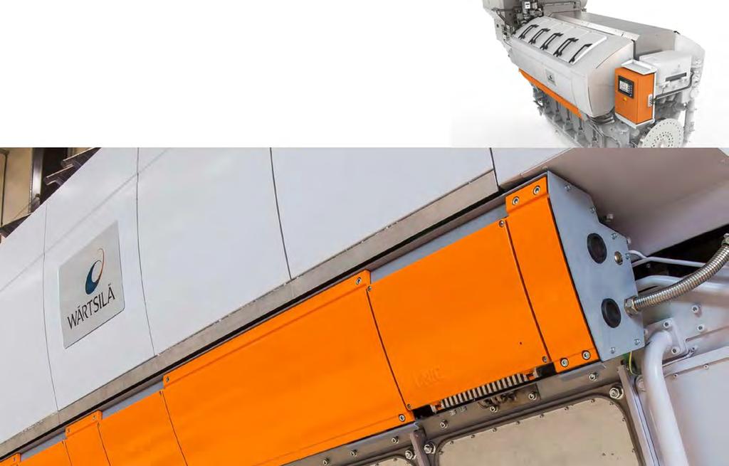
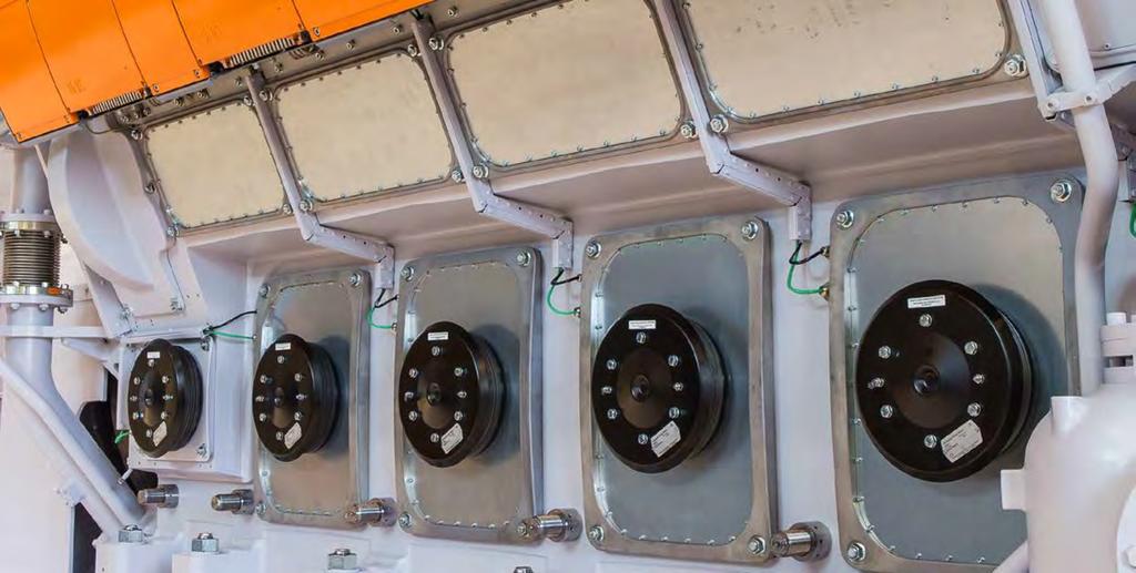
184
Wärtsilä 46F PRODUCT GUIDE
 Wärtsilä 46F PRODUCT GUIDE Copyright by WÄRTSILÄ FINLAND Oy All rights reserved. No part of this booklet may be reproduced or copied in any form or by any means (electronic, mechanical, graphic, photocopying,
Wärtsilä 20 PRODUCT GUIDE
 Wärtsilä PRODUCT GUIDE Copyright by WÄRTSILÄ FINLAND OY All rights reserved. No part of this booklet may be reproduced or copied in any form or by any means (electronic, mechanical, graphic, photocopying,
Wärtsilä Auxpac PRODUCT GUIDE
 Wärtsilä Auxpac PRODUCT GUIDE Copyright by WÄRTSILÄ FINLAND OY All rights reserved. No part of this booklet may be reproduced or copied in any form or by any means (electronic, mechanical, graphic, photocopying,
Wärtsilä 32 PRODUCT GUIDE
 Wärtsilä 32 PRODUCT GUIDE Copyright by WÄRTSILÄ FINLAND OY All rights reserved. No part of this booklet may be reproduced or copied in any form or by any means (electronic, mechanical, graphic, photocopying,
Wärtsilä 50DF PRODUCT GUIDE
 Wärtsilä 50DF PRODUCT GUIDE Copyright by WÄRTSILÄ FINLAND Oy All rights reserved. No part of this booklet may be reproduced or copied in any form or by any means (electronic, mechanical, graphic, photocopying,
Introduction. Application Technology Wärtsilä Diesel Oy, Marine. Vaasa, 24 March 1997
 Introduction Introduction The Project Guide provides main engine data and system proposals for the early design phase of engine installations. For contracted projects specific instructions for planning
WÄRTSILÄ 20DF PRODUCT GUIDE
 WÄRTSILÄ 20DF PRODUCT GUIDE Copyright by WÄRTSILÄ FINLAND Oy All rights reserved. No part of this booklet may be reproduced or copied in any form or by any means (electronic, mechanical, graphic, photocopying,
This document, and more, is available for download from Martin's Marine Engineering Page -
 Introduction This Project Guide provides engine data and system proposals for the early design phase of marine engine installations. For contracted projects specific instructions for planning the installation
MITSUBISHI DIESEL ENGINE IFM NO. JN (1/6) TECHNICAL INFORMATION DATE Aug. 8, 2002
 TECHNICAL INFORMATION DATE Aug. 8, 2002") DIESEL ENGINE IFM NO. JN02411-011(1/6) TECHNICAL INFORMATION DATE Aug. 8, 2002 TITLE Specification Sheets of S6U-MPTK Engine (IMO Certified Engine) Specification Sheets of S6U-MPTK Engine that is satisfied
DIESEL ENGINE IFM NO. JN02411-011(1/6) TECHNICAL INFORMATION DATE Aug. 8, 2002 TITLE Specification Sheets of S6U-MPTK Engine (IMO Certified Engine) Specification Sheets of S6U-MPTK Engine that is satisfied
Not to be reproduced without permission Last date for receipt of BIS or used as STANDARD of comments 15 September 2011
 For Comments Only Doc: TED 19(821)W July 2011 Draft Indian Standard SHIPBUILDING TESTING OF MARINE DIESEL ENGINES- CODE OF PRACTICE (Second Revision of IS 3979) Not to be reproduced without permission
Technical Sales Document
 1/23 Reference conditions 6 Intake air temperature 25 C 7 Chargeair coolant temperature C 8 Barometric pressure 1000 mbar 9 Site altitude above sea level 100 m 2/23 0. Datarelevant engine design configuration
MTU Friedrichshafen. MTU Project No. - ENGINE DATA - Printout: (y-m-d) Sheet 1
 Sheet 1") Printout: (y-m-d) 2006-08-09 Sheet 1 0. DATA-RELEVANT ENGINE DESIGN CONFIGURATION 1 Fuel-consumption optimized X 2 Exhaust-emissions optimized (limit values see Exhaust Emissions, Chapter 21) 47 "TA-Luft"
Printout: (y-m-d) 2006-08-09 Sheet 1 0. DATA-RELEVANT ENGINE DESIGN CONFIGURATION 1 Fuel-consumption optimized X 2 Exhaust-emissions optimized (limit values see Exhaust Emissions, Chapter 21) 47 "TA-Luft"
Technical Specification
 Technical Specification including performance data Project 3 x 9CM25 rev 2. consisting of 3 Caterpillar Diesel Generator sets Type 9CM25 with site output of: 2475 bkw at each engine flywheel rated 750
1506A-E88TAG5. Series. 293 kwm 1500 rpm 333 kwm 1800 rpm. Basic technical data
 1506A-E88TAG5 293 kwm standby @ 1500 rpm 333 kwm standby @ 1800 rpm 1500 Series Basic technical data Number of cylinders............................................................6 Cylinder arrangement....................................................
Technical Sales Document
 1/22 Product Data 10 Ref. 25 C/; Air charge air cooling TALuft optimized (Diesel); Reference conditions 6 Intake air temperature 25 C 7 Chargeair coolant temperature C 8 Barometric pressure 1000 mbar 9
General 4-stroke direct injected, turbocharged and aftercooled diesel engine
 General 4-stroke direct injected, turbocharged and aftercooled diesel engine Number of cylinders No of valves Displacement, total Firing order Rotational direction, viewed from the front Bore Stroke Compression
TAG3. Diesel engine - ElectropaK. Series kwm 1500 rpm. Basic technical data. Ratings. Total weight of ElectropaK
 1105 kwm Standby @ 1500 rpm Diesel engine - ElectropaK 4000 Series Basic technical data Number of cylinders............................................................8 Cylinder arrangement................................................
7,15 436, Bore , ,12 Compression ratio. 17 Wet weight
 General In-line four stroke diesel engine with direct injection. Rotation direction, anti-clockwise viewed towards flywheel. Turbocharged Number of cylinders 6 Displacement, total Firing order in 3 7,15
7,15 436, Bore , ,12 Compression ratio. 18 Wet weight
 General In-line four stroke diesel engine with direct injection. Rotation direction, anti-clockwise viewed towards flywheel. Turbocharged Number of cylinders 6 Displacement, total Firing order in 3 7,15
General 4-stroke direct injected, turbocharged and aftercooled diesel engine
 D11B-A (R-51IB) 5 General 4-stroke direct injected, turbocharged and aftercooled diesel engine Number of cylinders No of valves Displacement, total Firing order Rotational direction, viewed from the front
G-Drive Engine Data Sheet
 6M26D484E200 Speed Ratings Definitions G-Drive Engine Data Sheet Gross Engine Output COP PRP ESP rpm kwm kwm kwm 10 368 440 484 Continuous Power(COP) Prime Power (PRP) (ESP) Mean engine load factor 100%
General 4-stroke direct injected, turbocharged and aftercooled diesel engine
 D11B3-A (R-625IB) 5 General -stroke direct injected, turbocharged and aftercooled diesel engine Number of cylinders No of valves Displacement, total Firing order Rotational direction, viewed from the front
Maintenance schedules / maintenance parts
 SPARE PARTS NOTICE (W-internal) Services, Wärtsilä Netherlands B.V. Engine section Engine type Ref. Date Issue Document No. Page 99 Service information D234 WNL Services 31.10.2012 04 SN234/99/7001 1(1)
12,78 779, Bore , ,22 Compression ratio. 18,1:1 Wet weight. Engine incl. cooling system, air filtration system, and frame
 General Inline four stroke diesel engine with direct injection. Rotation direction, anticlockwise viewed towards flywheel. Turbocharged Number of cylinders 6 Displacement, total Firing order in 3 12,78
4016TAG1A 4016TAG2A. Series kwm 1500 rpm kwm 1500 rpm ElectropaK. Ratings. Basic technical data
 4016TAG1A 1270-1741 kwm (Gross) @ 1500 rpm 1413-1937 kwm (Gross) @ 1500 rpm ElectropaK Basic technical data Number of cylinders...................................................16 Cylinder arrangement..........................................
Flushing Instruction
 Copyright WinGD. All rights reserved. By taking possession of the drawing, the recipient recognizes and honors these rights. Neither the who le nor any part of this drawing may be used in any way for construction,
Natural gas engine E 0836 LE 202 Technical data
 Page 1 Principle: No of cylinders : Supercharging: Mixture cooling: Engine cooling : Lubrication : Spark plugs: Starter motor: 4-stroke Otto gas engine 6 in line Exhaust turbocharger with water-cooled
DEUTZ Engine Documentation Genset Manual. BF4M2012C (D2OC74,9) - 50 Hz 1/5 DEUTZ AG
 - 50 Hz 1/5 DEUTZ AG") 1/5 DEUTZ AG Technical data General engine data Engine Type BF4M2012C EKZ 11372 Speed 1500 min -1 Net frequency Exhaust emission standard 50 Hz Stage II Specific engine data Aspiration No of cylinders
1/5 DEUTZ AG Technical data General engine data Engine Type BF4M2012C EKZ 11372 Speed 1500 min -1 Net frequency Exhaust emission standard 50 Hz Stage II Specific engine data Aspiration No of cylinders
3516B MARINE PROPULSION SPECIFICATIONS STANDARD ENGINE EQUIPMENT mhp (2447 bhp) 1825 bkw
 1825 bkw") 2482 mhp (2447 bhp) 1825 bkw Image shown may not reflect actual SPECIFICATIONS V-16, 4-Stroke-Cycle-Diesel Emissions... EPA T1-IMO Displacement... 78.08 L (4,764.73 in 3 ) Rated Speed...1600 Bore... 170.0
2482 mhp (2447 bhp) 1825 bkw Image shown may not reflect actual SPECIFICATIONS V-16, 4-Stroke-Cycle-Diesel Emissions... EPA T1-IMO Displacement... 78.08 L (4,764.73 in 3 ) Rated Speed...1600 Bore... 170.0
Technical Data TWG2A TWG3A Series. Diesel Engine - ElectropaK rev/min. Basic technical data
 Technical Data 4000 Series Diesel Engine - ElectropaK Basic technical data Number of cylinders...................................................12 Cylinder arrangement..........................................
Technical File and Copy of United States Environmental Protection Agency (EPA) Statement of Compliance
 Statement of Compliance") Technical File and Copy of United States Environmental Protection Agency (EPA) Statement of Compliance MARINE DIESEL ENGINES D4.2L 230 (4.2 MS 230 and 4.2 MI 230 Model) IMPORTANT: To comply with regulations
Technical File and Copy of United States Environmental Protection Agency (EPA) Statement of Compliance MARINE DIESEL ENGINES D4.2L 230 (4.2 MS 230 and 4.2 MI 230 Model) IMPORTANT: To comply with regulations
S16U-TA MITSUBISHI DIESEL ENGINES
 S16U-TA GENERAL ENGINE DATA Type... 4-Cycle, Water Cooled Aspiration... Turbo-Carged, After Cooler (Jacket Water to Cooler) Cylinder Arrangement... 60 V No. of Cylinders... 16 Bore mm (in.)... 240 (9.45)
Ratings TAG2A (1500 rpm)...1: TAG2A (1800 rpm)...1: TAG3A (1500 rpm)...1: TAG3A (1800 rpm)...
...1: TAG2A (1800 rpm)...1: TAG3A (1500 rpm)...1: TAG3A (1800 rpm)...") 527-746 kwm (Gross) @ 1500/1800 rpm 566-839 kwm (Gross) @ 1500/1800 rpm ElectropaK Basic technical data Number of cylinders............................................................6 Cylinder arrangement.......................................
527-746 kwm (Gross) @ 1500/1800 rpm 566-839 kwm (Gross) @ 1500/1800 rpm ElectropaK Basic technical data Number of cylinders............................................................6 Cylinder arrangement.......................................
General 4-stroke direct injected, turbocharged and aftercooled diesel engine
 General 4-stroke direct injected, turbocharged and aftercooled diesel engine Number of cylinders No of valves Displacement, total Firing order Rotational direction, viewed from the front Bore Stroke Compression
3516B MARINE PROPULSION SPECIFICATIONS STANDARD ENGINE EQUIPMENT mhp (2200 bhp) 1641 bkw
 1641 bkw") 2231 mhp (2200 bhp) 1641 bkw Image shown may not reflect actual SPECIFICATIONS V-16, 4-Stroke-Cycle-Diesel Emissions... EPA T1-IMO Displacement... 69.06 L (4,214.3 in 3 ) Rated Speed...1800 Bore... 170.0
2231 mhp (2200 bhp) 1641 bkw Image shown may not reflect actual SPECIFICATIONS V-16, 4-Stroke-Cycle-Diesel Emissions... EPA T1-IMO Displacement... 69.06 L (4,214.3 in 3 ) Rated Speed...1800 Bore... 170.0
1106A-70TAG4. Series kwm 1500 rpm ElectropaK. Basic technical data. General installation
 1106A-70TAG4 196.3 kwm (Gross) @ 1500 rpm ElectropaK Basic technical data Number of cylinders.......................................................6 Cylinder arrangement................................................in-line
7,15 436, Bore , ,12 Compression ratio 18 Wet weight. Engine incl. cooling system and air filtration system
 Document No General In-line four stroke diesel engine with direct injection. Rotation direction, anti-clockwise viewed towards flywheel. Turbocharged Number of cylinders 6 Displacement, total Firing order
Introduction. Wärtsilä Nederland B.V. Marine P.O. Box GB Zwolle Nederland. Introduction
 Introduction Introduction This 1/2002 issue replaces all previous issues of the Wärtsilä 38 Project Guide. Major revisons of issue 1/2002 are: Technical data sheets revised Internal system diagrams revised
3516B SPECIFICATIONS. Lube System. gear type oil pump, gear type scavenge oil pump Dual Caterpillar A-III electronic engine control, Mounting System
 2840 mhp (2800 bhp) 2088 bkw Image shown may not reflect actual SPECIFICATIONS V-16, 4-Stroke-Cycle-Diesel Emissions... EPA T1-IMO Displacement... 69.0 L (4,210.64 in 3 ) Rated Speed...1880 Bore... 170.0
4,76 290,7 Firing order Bore
 General In-line four stroke diesel engine with direct injection. Rotation direction, anti-clockwise viewed towards flywheel. Turbocharged Number of cylinders 4 Displacement, total litre in 3 4,76 29,7
Technical Data TRG TRG TRG Series
 Technical Data 4000 Series Diesel Engine Basic technical data Number of cylinders................................................... 16 Cylinder arrangement.......................................... 60
TAG2A TAG3A. Series kwm 1500/1800 rpm kwm 1500/1800 rpm ElectropaK. Ratings. Basic technical data
 4006-23TAG2A 527-746 kwm (Gross) @ 1500/10 rpm 4006-23TAG3A 566-839 kwm (Gross) @ 1500/10 rpm ElectropaK 4000 Series Basic technical data Number of cylinders....................................................6
@Perkins. Technical Data Series TAG1A TAG2A TAG3A. Diesel Engine - Electropak. Basic technical data
 Technical Data Basic technical data Number of cylinders.................................................... 6 Cylinder arrangement................................... Vertical, In line Cycle....................................4
Technical File and Copy of United States Environmental Protection Agency (EPA) Statement of Compliance
 Statement of Compliance") Technical File and Copy of United States Environmental Protection Agency (EPA) Statement of Compliance MARINE DIESEL ENGINES D7.3L DI LD / D7.3L D-Tronic (Mercury MerCruiser D7.3L LD D-Tronic and D7.3L
Technical File and Copy of United States Environmental Protection Agency (EPA) Statement of Compliance MARINE DIESEL ENGINES D7.3L DI LD / D7.3L D-Tronic (Mercury MerCruiser D7.3L LD D-Tronic and D7.3L
Engine incl. cooling system and air filtration system Engine incl. cooling system, air filtration system, and frame. Standby Power
 20110216 General Inline four stroke diesel engine with direct injection. Rotation direction, anticlockwise viewed towards flywheel. Turbocharged Number of cylinders 6 Displacement, total Firing order in
Engine incl. cooling system and air filtration system Engine incl. cooling system, air filtration system, and frame. Standby Power.
 Important This Technical Data Sheet and the corresponding Installation Instructions provide important information to ensure the installed engine will operate according to the design specification in the
1.2 For the purpose of this UR, the following definitions apply: Low-Speed Engines means diesel engines having a rated speed of less than 300 rpm.
 (Feb 2015) (Corr.1 June 2016) Type Testing of I.C. Engines 1. General 1.1 Type approval of I.C. engine types consists of drawing approval, specification approval, conformity of production, approval of
Continuous Baseload. Prime Power
 Technical Data 4000 Series Diesel Engine - Electrounit Basic technical data Number of cylinders..................................................... 8 Cylinder arrangement.............................................
Medium speed generator sets Products and applications
 Medium speed generator sets Products and applications 1 Why invest in medium speed engines? Quick ramp up and ramp down times to support grid fluctuations and variable renewables generation Continuous
MARINE PROPULSION SPECIFICATIONS STANDARD ENGINE EQUIPMENT. 320 mhp (315 bhp) 235 bkw
 235 bkw") 320 mhp (315 bhp) 235 bkw Image shown may not reflect actual SPECIFICATIONS I-6, 4-Stroke-Cycle-Diesel Emissions...IMO Displacement... 7.2 L (442 cu in) Rated Speed...2400 Bore... 110 mm (4.33 in) Stroke...
320 mhp (315 bhp) 235 bkw Image shown may not reflect actual SPECIFICATIONS I-6, 4-Stroke-Cycle-Diesel Emissions...IMO Displacement... 7.2 L (442 cu in) Rated Speed...2400 Bore... 110 mm (4.33 in) Stroke...
Technical data TAD1353GE
 General Inline four stroke diesel engine with direct injection. Rotation direction, anticlockwise viewed towards flywheel. Turbocharged Number of cylinders 6 Displacement, total Firing order in 3 12,78
Technical data TAD1352GE
 General Inline four stroke diesel engine with direct injection. Rotation direction, anticlockwise viewed towards flywheel. Turbocharged Number of cylinders 6 Displacement, total Firing order in 3 12,78
Technical Data 4008TAG 4008TAG1 4008TAG Series. Diesel Engine - ElectropaK
 Technical Data 4000 Series Diesel Engine - ElectropaK Basic technical data Number of cylinders..................................................... 8 Cylinder arrangement.............................................
INTERNATIONAL MARITIME ORGANIZATION (IMO) Technical File and Copy of United States Environmental Protection Agency (EPA) Statement of Compliance
 Technical File and Copy of United States Environmental Protection Agency (EPA) Statement of Compliance") INTERNATIONAL MARITIME ORGANIZATION (IMO) Technical File and Copy of United States Environmental Protection Agency (EPA) Statement of Compliance MARINE DIESEL ENGINES Base Engine MR706L Cummins MerCruiser
INTERNATIONAL MARITIME ORGANIZATION (IMO) Technical File and Copy of United States Environmental Protection Agency (EPA) Statement of Compliance MARINE DIESEL ENGINES Base Engine MR706L Cummins MerCruiser
General In-line four stroke diesel engine with direct injection. Rotation direction, anti-clockwise viewed towards flywheel
 Important This Technical Data Sheet and the corresponding Installation Instructions provide important information to ensure the installed engine will operate according to the design specification in the
1106A-70TAG4. Series kwm 1500rpm ElectropaK. Basic technical data
 1106A-70TAG4 196.3 kwm (Gross) @ 1500rpm ElectropaK Basic technical data Number of cylinders....................................................................6 Cylinder arrangement...........................................................in-line
Diesel engine D 2866 LE20x Technical Data
 page 1 Engine type: Cylinders : Aspiration : Cooling : Lubrication: Injection: Generator: Starter motor: four-stroke, direct-injection 6 cylinder in line, wet replaceable cylinder liners turbocharger,
Technical data TAD1242GE. General
 General In-line four stroke diesel engine with direct injection. Rotation direction, anti-clockwise viewed towards flywheel. Turbocharged Number of cylinders 6 Displacement, total litre 12,13 in 3 740,2
Technical data TAD1241GE. General
 General In-line four stroke diesel engine with direct injection. Rotation direction, anti-clockwise viewed towards flywheel. Turbocharged Number of cylinders 6 Displacement, total litre 12,13 in 3 740,2
11,000 teu container vessel
 11,000 teu container vessel An ME-GI powered vessel fitted with fuel gas supply system and boil-off gas handling 2 MAN Energy Solutions 11,000 teu container vessel Future in the making 3 Contents Main
General In-line four stroke diesel engine with direct injection. Rotation direction, counterclockwise viewed towards flywheel
 Important This Technical Data Sheet and the corresponding Installation Instructions provide important information to ensure the installed engine will operate according to the design specification in the
Technical Data 2506A-E15TAG3 2506A-E15TAG Series. Diesel Engine - ElectropaK
 Technical Data 2500 Series Diesel Engine - ElectropaK 2506A-E15TAG3 2506A-E15TAG4 Basic technical data Number of cylinders................................................................ 6 Cylinder arrangement..............................................
Power where you need it...when you need it!!!
 Important This Technical Data Sheet and the corresponding Installation Instructions provide important information to ensure the installed engine will operate according to the design specification in the
Marine Engine. IMO Tier ll and Tier lll Programme 2nd edition 2016
 Marine Engine IMO Tier ll and Tier lll Programme 2nd edition 2016 All data provided in this document is non-binding. This data serves informational purposes only and is especially not guaranteed in any
Power where you need it...when you need it!!!
 Important This Technical Data Sheet and the corresponding Installation Instructions provide important information to ensure the installed engine will operate according to the design specification in the
L58/64, L48/60, V48/ L40/54, L32/40, V32/ L28/32A, V28/32A, L27/ L23/30A, V23/30A, 48 L32/40DG, V32/40DG 49-50
 Contents Two-stroke Propulsion Engines 4-35 K98MC, K98MC-C, 11-12 S90MC-C, L90MC-C, K90MC, K90MC-C, 13-16 S80MC-C, S80MC, L80MC, K80MC-C, 17-20 S70MC-C, S70MC, L70MC 21-23 S60MC-C, S60MC, L60MC, 24-26
Technical File and Copy of United States Environmental Protection Agency (EPA) Statement of Compliance
 Statement of Compliance") Technical File and Copy of United States Environmental Protection Agency (EPA) Statement of Compliance MARINE DIESEL ENGINES D4.2L IDI (Mercury MerCruiser D4.2L Model) IMPORTANT: To comply with regulations
Technical File and Copy of United States Environmental Protection Agency (EPA) Statement of Compliance MARINE DIESEL ENGINES D4.2L IDI (Mercury MerCruiser D4.2L Model) IMPORTANT: To comply with regulations
TRG TRG TRG3
 1269-2074 kwm (Gross) @ 1500 rpm Emissions compliant Electrounit Basic technical data Number of cylinders................................................................. 16 Cylinder arrangement.........................................................
144 5, ,50 Compression ratio 16,5:1 Dry weight. Engine only, excluding cooling system GenPac. Engine only, excluding cooling system GenPac
 General Inline four stroke diesel engine with direct injection. Rotation direction, anticlockwise viewed towards flywheel. Turbocharged Number of cylinders 6 Displacement, total Firing order in 3 16,12
D9 MG HE Base on water temp 38 C/100 F General
 Base on water temp 38/0 General In-line four stroke diesel engine with direct injection. Rotation direction, anti-clockwise viewed towards flywheel. Turbocharged Number of cylinders 6 Displacement, total
1200 Series E70 TAG1M Marine Auxiliary Engine 109 kw ( rpm
 Based on Perkins universally acclaimed 1206 Series and renowned throughout the power generation industry for its superior performance and reliability. The Perkins E70M is a turbocharged, charge air-cooled,
Technical Data 2506C-E15TAG3 2506C-E15TAG Series. Diesel Engine - ElectropaK
 Technical Data 2500 Series Diesel Engine - ElectropaK 2506C-E15TAG3 2506C-E15TAG4 Basic technical data Number of cylinders................................................................ 6 Cylinder arrangement..............................................
ENGINE PERFORMANCE CURVE M1-158 hp ( rpm
 Rating: ENGINE PERFORMANCE CURVE M1-158 hp (118 kw) @ 0 rpm PowerTech 6.8 L Engine Model: 6068TFM75 Application: Marine (Propeller Power is approximately 97% of Crankshaft Power) Power -- hp (kw) (179)
Technical data TWD1643GE
 General Inline four stroke diesel engine with direct injection. Rotation direction, anticlockwise viewed towards flywheel. Turbocharged Number of cylinders 6 Displacement, total in 3 16,12 983,7 Firing
Biogas Engine E 0836 LE 202 Technical Data for 60%-CH 4, 40%-CO 2
 Page 1 Principle: 4-stroke Otto gas engine No of cylinders : 6 in line Supercharging: Exhaust turbocharger with water-cooled turbine housing, pressure-lubricated bearings and water-cooled bearing pedestal.
C87 ENT 260 kw ( rpm rpm Stage IIIA / Tier 3
 C87 ENT 260 kw (354 HP) @ 2100 rpm - 1500 Nm @ 1400 rpm SPECIFICATIONS Technical code F2CE9687A*EXX Thermodynamic cycle Diesel 4 stroke Air intake TAA Arrangement 6L Bore x Stroke mm 117 x 135 Total displacement
@Perkins. Technical Data Series 2806C-E18TAG3. Diesel Engine - ElectropaK. Cyclic irregularity. Basic technical data. Ratings.
 Technical Data @Perkins 2800 Series 2806C-E18TAG3 Diesel Engine - ElectropaK Basic technical data Number of cylinders..................................................... 6 Cylinder arrangement...................................
C9 ACERT MARINE PROPULSION SPECIFICATIONS STANDARD ENGINE EQUIPMENT. 575 mhp (567 bhp)
") 575 mhp (567 bhp) 423 bkw Image shown may not reflect actual SPECIFICATIONS I-6, 4-Stroke-Cycle-Diesel Emissions... IMO compliant Displacement... 8.82 L (538.23 in 3 ) Rated Speed...2500 Bore... 112.0
575 mhp (567 bhp) 423 bkw Image shown may not reflect actual SPECIFICATIONS I-6, 4-Stroke-Cycle-Diesel Emissions... IMO compliant Displacement... 8.82 L (538.23 in 3 ) Rated Speed...2500 Bore... 112.0
1106A-70TAG3. Series kwm 1500rpm ElectropaK. Basic technical data
 1106A-70TAG3 180.2 kwm (Gross) @ 1500rpm ElectropaK Basic technical data Number of cylinders....................................................................6 Cylinder arrangement...........................................................in-line
Engine only. Engine only. without fan kw hp with fan kw hp Power setting
 General In-line four stroke diesel engine with direct injection. Rotation direction, anti-clockwise viewed towards flywheel. Turbocharged Number of cylinders 6 Displacement, total Firing order litre in
C280-8 MARINE PROPULSION
 C280-8 MARINE PROPULSION 3084 bhp (2300 bkw) 900 rpm SPECIFICATIONS Shown with Accessory Equipment In-Line 8, 4-Stroke-Cycle-Diesel Emissions.................. IMO/EPA Tier 2 Compliant Bore mm (in)...
1606A-E93TAG4. Series kwm 1800 rpm ElectropaK. Basic technical data. Performance. Test conditions. Notes:
 1606A-E93TAG4 287-314 kwm (Gross) @ 1800 rpm ElectropaK 1600 Series Basic technical data Number of cylinders.....................................................6 Cylinder arrangement.............................................in-line
@Perkins. Technical Data Series 2806A-E18TAG1A. Basic technical data. Cyclic irregularity for engine/flywheel maximum: Ratings.
 Technical Data @Perkins 2800 Series 2806A-E18TAG1A Diesel Engine - ElectropaK 2806A-E18TAG2 Basic technical data Number of cylinders..................................................... 6 Cylinder arrangement...................................
@Perkins. Technical Data Series 2806C-E18TAG1A. Diesel Engine - ElectropaK. Basic technical data. Cyclic irregularity. Ratings.
 Technical Data @Perkins 2800 Series 2806C-E18TAG1A Diesel Engine - ElectropaK Basic technical data Number of cylinders..................................................... 6 Cylinder arrangement...................................
MAN Diesel & Turbo. Main Engine Room Data. Project name BrasNave 25 Project type Project number 3 Date 2010 Yard
 MAN Diesel & Turbo Main Engine Room Data Main Engine Compliance 6S80MC6.1-TI IMO-NOx Tier I Project name BrasNave 25 Project type Project number 3 Date 2010 Yard Country Brasil Made by BrasNave Department
MARINE C18 SPECIFICATIONS. Lube System. service, oil level gauge - RH or LH service, oil filler, Cooling System
 486 mhp (479 bhp) 357 bkw Image shown may not reflect actual SPECIFICATIONS I-6, 4-Stroke-Cycle-Diesel Displacement... 18.1 L (1106 cu in) Rated Speed...1800 Bore... 145.0 mm (5.7 in) Stroke... 183.0 mm
MAN B&W Marine Engines MAN Holeby GenSets. IMO Tier ll 2012
 MAN B&W Marine Engines MAN Holeby GenSets IMO Tier ll 2012 All data provided in this document is non-binding. This data serves informational purposes only and is especially not guaranteed in any way. Depending
3056 MARINE PROPULSION
 056 MARINE PROPULSION 9 bkw (125 bhp) Image may not reflect actual engine SPECIFICATIONS I-6, -Stroke-Cycle-Diesel Bore... 100 mm (.9 in.) Stroke... 127 mm (5.0 in.) Displacement.................. 6 L
Technical data TAD740GE
 Technical data TAD740GE General In-line four stroke diesel engine with direct injection Turbo charged and air to air intercooled Rotation direction, anti-clockwise viewed towards flywheel Number of cylinders
1100 Series 4.4TW2GM Marine Auxiliary Engine kw (143.2 hp) gross prime 1800 rpm
 gross prime 1800 rpm") Building upon Perkins proven reputation within the marine power generation industry. The 4.4 Series range of Marine Auxiliary engines now fit even closer to the needs of their customers. In the world of
Building upon Perkins proven reputation within the marine power generation industry. The 4.4 Series range of Marine Auxiliary engines now fit even closer to the needs of their customers. In the world of
1106A-70TAG2. Series kwm 1800rpm ElectropaK. Basic technical data
 1106A-70TAG2 163.8 kwm (Gross) @ 1800rpm ElectropaK Basic technical data Number of cylinders....................................................................6 Cylinder arrangement...........................................................in-line
MARINE PROPULSION SPECIFICATIONS STANDARD ENGINE EQUIPMENT. 375 mhp (370 bhp)
") 375 mhp (370 bhp) 276 bkw Image shown may not reflect actual SPECIFICATIONS I-6, 4-Stroke-Cycle-Diesel Emissions...IMO Displacement... 7.2 L (442 cu in) Rated Speed...2600 Bore... 110 mm (4.33 in) Stroke...
375 mhp (370 bhp) 276 bkw Image shown may not reflect actual SPECIFICATIONS I-6, 4-Stroke-Cycle-Diesel Emissions...IMO Displacement... 7.2 L (442 cu in) Rated Speed...2600 Bore... 110 mm (4.33 in) Stroke...
@Perkins. Technical Data. 1106D-E66TAG3 159, rev/min. 1100D Series. ElectropaK
 Technical Data 1100D Series ElectropaK Basic technical data Number of cylinders..................................................... 6 Cylinder arrangement............................................ In-Line
Technical Data. 400 Series 403D-15G. ElectropaK
 Technical Data 400 Series 403D-15G ElectropaK Basic technical data Number of cylinders.................................................... 3 Cylinder arrangement.................................... Vertical
7. Lubricating Oil System
 7.1 Lubricating oil requirements 7.1.1 Engine lubricating oil The lubricating oil must be of viscosity class SAE 40 and have a viscosity index (VI) of minimum 95. The lubricating oil alkalinity (BN) is
4008 TAG1A 4008 TAG2A. Series kwm 1500 rpm kwm 1500 rpm ElectropaK. Basic technical data.
 4008 TAG1A 644-882 kwm (Gross) @ 1500 rpm 4008 TAG2A 715-985 kwm (Gross) @ 1500 rpm ElectropaK Basic technical data Number of cylinders....................................................8 Cylinder arrangement............................................
@Perkins. Technical Data. 192, rev/min. ElectropaK
 Technical Data 1100D Series ElectropaK @Perkins 1106D-E66TAG4 192,3 kwm @ 1800 rev/min Basic technical data Number of cylinders..................................................... 6 Cylinder arrangement............................................
@Perkins. Technical Data. 400 Series 403D-11G. ElectropaK
 Technical Data @Perkins 400 Series 403D-11G ElectropaK Basic technical data Number of cylinders.................................................... 3 Cylinder arrangement....................................
3512C MARINE PROPULSION SPECIFICATIONS STANDARD ENGINE EQUIPMENT mhp (2550 bhp) 1902 bkw
 1902 bkw") 2586 mhp (2550 bhp) 1902 bkw Image shown may not reflect actual SPECIFICATIONS V-12, 4-Stroke-Cycle-Diesel Emissions...IMO Compliant Displacement... 58.56 L (3,573.55 in 3 ) Rated Speed...1800 Bore...
2586 mhp (2550 bhp) 1902 bkw Image shown may not reflect actual SPECIFICATIONS V-12, 4-Stroke-Cycle-Diesel Emissions...IMO Compliant Displacement... 58.56 L (3,573.55 in 3 ) Rated Speed...1800 Bore...
Industrial Diesel Generator Set KD3500-F 50 Hz Fuel Consumption Optimized
 RATINGS 400 V - 50 Hz Standby kva 3500 KWe 2800 Prime kva 3182 KWe 2546 Benefits & features premium quality provides one source responsibility for the generating system and accessories The generator set,