Holemaking ADVANCES 2017 Inch
|
|
|
- Basil Smith
- 5 years ago
- Views:
Transcription


1 Holemaking ADVANCES 2017 Inch
2
3 Holemaking Introduction... Q1 Q8 Solid Carbide Drills... R1 R139 Modular Drills...S1 S51 Indexable Drills... T1 T60 Hole Finishing... U1 U95 Q1
4 Holemaking Made Easy and Economical From sturdy, general-purpose solid carbide drills to high-precision fine boring systems, we offer the most comprehensive line of holemaking products available on the market today. If you need unmatched performance and reliability, look no further than our wide range of solid carbide, modular, and indexable drills, and hole finishing products. Solid Carbide Drills VariDrill TOP DRILL S for Steel Modular Drills TOP DRILL M1 Spade Blades TOP DRILL S for Cast Iron TOP DRILL S+ TOP DRILL S+ 12 x D TOP DRILL Deep-Hole Drill TOP DRILL G Q2
5 TOP DRILL S Victory TOP DRILL M1 Top Cut 4 ROTAFLEX Indexable Drills Top Cut 4 Hole Finishing Reaming Tools ROTAFLEX Boring System Countersinking Tools Q3


 normal (M/C) high (fine) hole quality IT11 IT10 IT9 IT8 IT7 IT6 diameter Solid Carbide Drills 0.118\" (3mm).")
6 Choosing the Correct Production Holemaking Added Value for Your Performance Increase of Productivity and Efficiency Material and application-specific solutions. Maximum metal removal rates and repeatability. Standardized design platforms for special tools based on proven solutions for individual optimizations and combination tools. Optimized Purchase Broad selection of holemaking tools. Integrated into a full range of cutting tools and service offers. Onsite service for an efficient development and implementation of machining solutions. Control of Total Tooling Costs High tool utilization through material and applicationspecific solutions. Process-safe regrinding service. Reduction of stocks through efficient modular concepts. Multiple platforms per application to achieve the most cost-efficient solution. Select the Correct Holemaking Product Platform for Your Application hourly rate low (rough) normal (M/C) high (fine) hole quality IT11 IT10 IT9 IT8 IT7 IT6 diameter Solid Carbide Drills 0.118" (3mm) in. (1 25mm) 0.236" (6mm) 0.354" (9mm) 0.472" (12mm) 0.591" (15mm) 0.709" (18mm) WIDIA Spade Blades in. (9,2 101,6mm) Top Cut in. (12 68mm) Top Drill M in. (7,94 27,99mm) 0.827" (21mm) 0.945" (24mm) Solid Drilling 1.063" (27mm) 1.181" (30mm) 1.299" (33mm) 1.417" (36mm) 1.535" (39mm) 1.654" (42mm) 1.772" (45mm) 2.283" (58mm) 2.008" (51mm) 2.126" (54mm) 2.244" (57mm) 2.362" (60mm) 4.331" (110mm) Q4
7 Choosing the Correct Production Holemaking Determine the hole quality and diameter to show the available options and then decide the platform that will best fulfi ll your requirements. Solid Carbide Drills Modular Drills Indexable Drills Precision Hole Finishing Reaming Select the Correct Holemaking Product Platform for Your Application hourly rate low (rough) normal (M/C) high (fine) hole quality IT11 IT10 IT9 IT8 IT7 IT6 diameter 0.118" (3mm) HSR SC-Reaming* 0.394" (10mm) 0.787" (20mm) 1.181" (30mm) 1.575" (40mm) ROTAFLEX TCHS Rough Boring Twin Cutter (up to 4.528") ROTAFLEX FBHBB Fine Boring Heads with Boring Bars ROTAFLEX FBH Fine Boring Heads with Insert Holders (up to 4.528") HSR-Tipped Reamer* 1.969" (50mm) 2.362" (60mm) 2.756" (70mm) Hole Finishing 3.150" (80mm) 3.543" (90mm) 3.937" (100mm) 4.331" (110mm) 4.724" (120mm) ROTAFLEX Bridge Tools: Roughing (3.425" 7.953") ROTAFLEX Bridge Tools: Finishing (3.425" 7.953") 5.118" (130mm) 5.512" (140mm) 5.906" (150mm) 6.299" (160mm) 6.693" (170mm) 7.087" (180mm) 7.480" (190mm) 7.874" (200mm) 8.268" (210mm) ROTAFLEX Bridge Tools: Roughing (7.874" ") ROTAFLEX Bridge Tools: Finishing (7.874" ") " (510mm) " (520mm) *IT6 is possible above 0.394" (10mm) for both HSR SC-reaming and HSR-tipped reamer in custom solutions. Q5
8 Solid Carbide Drills Grades and Grade Descriptions Coatings provide high-speed capability and are engineered for finishing to heavy roughing. P M K N S H Steel Stainless Steel Cast Iron Non-Ferrous High-Temp Alloys Hardened Materials wear resistance toughness Coating Grade Description WU25PD Composition: With a multilayered PVD TiN-TiAlN coating and a high-quality submicron carbide substrate, this grade gives a high level of wear resistance at medium to high cutting speeds. Application: First choice for high reliability in all materials. This grade should be used at medium to high speeds and feeds. It is a general purpose grade that performs very well for alloyed and high-alloy steel and cast iron, but can also be used with excellent performance in all other material groups. P M K N S H P WP20PD Composition: With a multilayered PVD TiN-TiAlN coating, a high-quality submicron carbide substrate and a state-of-the-art surface condition, this grade gives the highest level of wear resistance at high cutting speeds. Application: A high productivity grade for high speeds and feeds. First choice for high productivity with excellent reliability in alloyed and high-alloyed steels and cast irons. K Grade WK15PD Composition: With a newly developed unique multilayered PVD AlCrN coating and a high-quality submicron carbide substrate, this grade gives the highest level of wear resistance at high cutting speeds. Application: This grade offers extraordinary wear resistance in drilling of cast iron materials. With its high hot hardness it allows for high speed machining. K P WU20PD Composition: With a multilayered PVD TiN-TiAlN coating, a high-quality submicron carbide substrate and a state-of-the-art surface condition, this grade gives the highest level of wear resistance at high cutting speeds. Application: First choice for alloyed and high-alloyed steels and cast irons. A state-ofthe-art surface condition enables superior chip evacuation even when MQL is applied. K WN10HD Composition: This uncoated fine-grain carbide with high hardness offers excellent abrasive wear resistance. Application: First choice for precision drilling of non-ferrous materials. K N Q6
9 Modular and Indexable Drills Grades and Grade Descriptions Coatings provide high-speed capability and are engineered for finishing to light roughing. P M K N S H Steel Stainless Steel Cast Iron Non-Ferrous High-Temp Alloys Hardened Materials wear resistance toughness Coating Grade Description Composition: With a multilayered PVD TiN-TiAlN coating and a high-quality P submicron carbide substrate, this grade gives a high level of wear resistance at medium to high cutting speeds. M Application: First choice for high reliability in most materials. This grade should be used at medium to high speeds and feeds. It is a general purpose grade that performs K very well for alloyed and high-alloy steel and cast iron, but can also be used with excellent performance in stainless steels. WU25PD NOTE: Previously named K20FTiAlN. P WPK10CH Composition: With an advanced CVD TiCN-Al 2 O 3 coating combined with a cobalt-enriched carbide substrate, this grade offers a balanced combination of deformation resistance and edge toughness. Application: Offers outstanding abrasion and crater wear resistance for high-speed machining of steels and cast irons. Use for very high cutting speeds with low to medium feed rates. K Grade WU25CH Composition: Advanced CVD TiCN-Al2O3 coating together with a newly engineered tough carbide substrate. Ensures adequate deformation resistance and excellent edge strength and offers very good wear resistance over a wide range of machining conditions. Application: A high productivity grade with high speeds and feeds. First choice for high productivity with excellent reliability in steels, stainless steels, and cast iron rates. P M K P WU40PH Composition: With a multilayered PVD TiN-TiAlN coating and a tough substrate, this grade withstands interruptions and provides high wear resistance for long tool life. Application: First choice for high reliability in most materials. This grade should be used at medium speeds and high feeds due to sharper edges and as a grade for hightoughness applications. It covers steel, stainless steel, cast iron, and high-temp alloys under certain conditions. M K Q7
10 Hole Finishing Grades and Grade Descriptions Coatings provide high-speed capability and are engineered for finishing to heavy roughing. P M K N S H Steel Stainless Steel Cast Iron Non-Ferrous High-Temp Alloys Hardened Materials wear resistance toughness Coating Grade Description P K10F Composition: This uncoated fine-grain carbide with high hardness offers excellent abrasive wear resistance paired with excellent toughness for fine-finishing applications. Application: First choice for precision reaming of non-ferrous materials. N S P Grade K10F-DCFD Composition: With a PVD TiAlN coating and a fine-grain carbide substrate, this grade offers excellent wear resistance paired with excellent toughness for medium-speed fine-finishing applications. Application: First choice for precision reaming of steels, stainless steel, and cast irons. M K P CERMETDCFD Composition: With a PVD TiAlN coating and a cermet substrate, this grade offers exceptional wear resistance for high-speed fine-finishing applications. Application: First choice for precision reaming of steels and cast irons. K Q8
11 Notes
12

13 High-Performance Solid Carbide Drills Introduction... R2 R3 VariDrill... R6 R32 TOP DRILL S... R34 R63 TOP DRILL S+... R64 R86 TOP DRILL S+ 12 x D... R88 R93 TOP DRILL Deep-Hole Drills... R94 R107 TOP DRILL G... R108 R129 Technical Information... R132 R139 R1
14 Solid Carbide Drills Tool Selection Guide standard standard range solid carbide drills for external coolant or dry machining series grade first choice alternate choice diameter range hole P M K N S H tolerance min max min max drilling depth L/D1 VariDrill multiple-material drilling VDS20 WU25PD IT9 IT10 1,0 20, x 5 x TOP DRILL S for steel application-specific drilling TDS202 WP20PD IT9 IT10 3,0 20, x D TOP DRILL S for cast iron application-specific drilling TDS212 WK15PD IT9 IT10 3,0 20, x D TOP DRILL S+ multiple-application drilling TDS301 WU25PD IT9 IT10 3,0 20, x D standard standard range first choice alternate choice solid carbide drills with internal coolant channel series grade diameter range hole P M K N S H tolerance min max min max drilling depth L/D1 VariDrill multiple-material drilling VDS40 WU25PD IT9 IT10 1,0 20, x 8 x TOP DRILL S for steel application-specific drilling TDS40 WP20PD IT9 IT10 3,0 20, x 8 x TOP DRILL S for cast iron application-specific drilling TDS41 WK15PD IT9 IT10 3,0 20, x 8 x TOP DRILL S+ multiple-application drilling TDS50 WU25PD IT9 IT10 3,0 20, x 8 x TOP DRILL S+ 12 x D deep-hole drilling without piloting TDS504 WU20PD IT9 IT10 3,0 20, x 8 x TOP DRILL Deep superior deep-hole drilling TDD10 WU20PD IT9 IT10 3,0 20, x 30 x TOP DRILL G difficult drilling applications TDG53 WN10HD IT8 IT9 3,0 20, x 12 x TOP DRILL Flat-Bottom for flat-bottom applications TDF51 WU20PD IT9 IT10 WN15HD IT9 IT10 R2
15 Solid Carbide Drills Tool Selection Guide custom solution range standard engineered solution capabilities diameter range D1 mm min-max D1 in min-max drilling depth page(s) 1,0 20, x R8 R21 3,0 25, x R36 R41 3,0 25, x R36 R41 3,0 25, x R66 R69 engineered solution range standard engineered solution capabilities diameter range D1 mm min-max D1 in min-max drilling depth page(s) 1,0 20, x R8 R28 3,0 25, x R42 R59 2,4 20, x R42 R59 3,0 25, x R70 R82 2,4 16, x R90 R92 3,0 25, mm R96 R103 3,0 25, x R110 R128 3,0 25, x R33 3,0 25, x R33 R3
16 Solid Carbide Drills Recommendation Chart Solid Carbide Drills Recommendation Chart Versatile Application-specific General Purpose General Purpose Multipurpose Multipurpose High- Performance High- Performance Deep-Hole Drilling VariDrill VariDrill Top Drill S+ Top Drill S+ Top Drill S/G Top Drill S/G WIDIA TDS+ WIDIA TDD P Steel 3 x D - VDS201A 3 x D - VDS201F 5 x D - VDS202A 5 x D - VDS202F 3 x D - VDS401A 3 x D - VDS401F 5 x D - VDS402A 5 x D - VDS402F 8 x D - VDS403A 8 x D - VDS403F 3 x D - TDS301A 3 x D - TDS501A 5 x D - TDS502A 8 x D - TDS503A 5 x D - TDS202A 3 x D - TDS401A 5 x D - TDS402A 8 x D - TDS403A 12 x D - TDS504A 15 x D - TDD105Z 20 x D - TDD106Z 25 x D - TDD107Z 30 x D - TDD108Z M Stainless Steel 3 x D - VDS201A 3 x D - VDS201F 5 x D - VDS202A 5 x D - VDS202F 3 x D - VDS401A 3 x D - VDS401F 5 x D - VDS402A 5 x D - VDS402F 8 x D - VDS403A 8 x D - VDS403F 3 x D - TDS301A 3 x D - TDS501A 5 x D - TDS502A 8 x D - TDS503A WIDIA-Rübig Series Type WD 12 x D - TDS504A 15 x D - TDD105Z 20 x D - TDD106Z 25 x D - TDD107Z 30 x D - TDD108Z K Cast Iron 3 x D - VDS201A 3 x D - VDS201F 5 x D - VDS202A 5 x D - VDS202F 3 x D - VDS401A 3 x D - VDS401F 5 x D - VDS402A 5 x D - VDS402F 8 x D - VDS403A 8 x D - VDS403F 3 x D - TDS301A 3 x D - TDS501A 5 x D - TDS502A 8 x D - TDS503A 5 x D - TDS212A 3 x D - TDS411A 5 x D - TDS412A 8 x D - TDS413A 12 x D - TDS504A 15 x D - TDD105Z 20 x D - TDD106Z 25 x D - TDD107Z 30 x D - TDD108Z N Non-Ferrous 3 x D - VDS201A 3 x D - VDS201F 5 x D - VDS202A 5 x D - VDS202F 3 x D - VDS401A 3 x D - VDS401F 5 x D - VDS402A 5 x D - VDS402F 8 x D - VDS403A 8 x D - VDS403F 3 x D - TDS301A 3 x D - TDS501A 5 x D - TDS502A 8 x D - TDS503A 5 x D - TDG531A 8 x D - TDG532A 12 x D - TDG533A TDD* uncoated, sharp S Heat- Resistant Alloys, Titanium Alloys 3 x D - VDS201A 3 x D - VDS201F 5 x D - VDS202A 5 x D - VDS202F 3 x D - VDS401A 3 x D - VDS401F 5 x D - VDS402A 5 x D - VDS402F 8 x D - VDS403A 8 x D - VDS403F 3 x D - TDS301A 3 x D - TDS501A 5 x D - TDS502A 8 x D - TDS503A WIDIA-Rübig Series Type WD 12 x D - TDS504A 15 x D - TDD105Z 20 x D - TDD106Z 25 x D - TDD107Z 30 x D - TDD108Z H Hard Materials VDS 3 x D - M155 VDS TDS+ standard first choice alternate choice simple special R4
17 Notes

18 Multiple-Material Drilling WIDIA VariDrill The VariDrill advanced-point geometry design offers the ultimate solution for multipurpose drilling operations. It offers dependable tool life in all materials due to less chipping on the cutting edge. Reduced chipping on cutting edge means longer tool life. Geometry design offers strength and versatility. Delivers proper surface finish across multiple materials: steel, stainless steel, cast iron, aluminum, and high-temp alloys. VariDrill WIDIA WU25PD drilling grade Extremely high wear resistance and longer tool life. VariDrill core design Free chip flow and chip evacuation. VariDrill point design Long tool life in all materials; less chipping on cutting edge. Marginless design Distributes cutting forces evenly for less chipping on the cutting edge. Precision shank Low runout. R6

19 Innovative Technology VariDrill is a technologically advanced holemaking solution. These high-performance solid carbide drills were designed in Germany to provide the transportation, aerospace, general engineering, and energy industries with a tool that performs on multiple materials. Elegance, Strength, and Versatility The engineers at WIDIA developed an innovative new design to deliver drilling performance. These solid carbide drills have a distinctive geometry and marginless design. The VariDrill point is versatile enough to work through steel, stainless steel, cast iron, aluminum, and a range of high-temp alloys. Optimum Hole Quality The unique marginless design reduces chipping on the tool s edge and stabilizes cutting forces. This unique tool geometry enables chips to roll smoothly and evacuate easily, resulting in noticeably less friction, heat, jamming, and scratching. By minimizing these drilling issues, VariDrill delivers an optimum surface finish with every hole no matter the material. More Options and Longer Tool Life Aside from its uniquely engineered design, VariDrill also offers a broad portfolio of drilling options. With more than 2,200 items, VariDrill offers more choices than any other drill for general engineering operations. And because most drills can be reconditioned, your tools will gain extended life. VariDrill Innovatively designed and technologically advanced. Make VariDrill your go-to drill for hole after hole...after hole. R7
20 Solid Carbide Drills VariDrill Steel, Stainless Steel, Cast Iron, Aluminum, and High-Temp Alloys 3 x D For information on L, L3, and L4 max, see page R133. VDS201A VDS401A 3 x D VDS201A grade WU25PD TiAlN VDS401A grade WU25PD TiAlN D1 diameter first choice alternate choice Solid Carbide Drills order # catalog # order # catalog # mm in fraction wire size L4 max L3 L5 L LS D VDS201A , , VDS201A , , VDS201A , , VDS201A , , VDS201A , , VDS201A , , VDS201A , , VDS201A , , VDS201A , , VDS201A , , VDS201A , , VDS201A , , VDS201A , , VDS201A VDS401A , , VDS201A VDS401A , , VDS201A VDS401A , , VDS201A VDS401A , , VDS201A VDS401A , , VDS201A VDS401A , , VDS201A VDS401A , , VDS201A VDS401A , , VDS201A VDS401A , , VDS201A VDS401A , , VDS201A VDS401A , / , (continued) R8
21 Solid Carbide Drills VariDrill Steel, Stainless Steel, Cast Iron, Aluminum, and High-Temp Alloys 3 x D (VDS201A VDS401A 3 x D continued) VDS201A grade WU25PD TiAlN VDS401A grade WU25PD TiAlN D1 diameter first choice alternate choice order # catalog # order # catalog # mm in fraction wire size L4 max L3 L5 L LS D VDS201A VDS401A , , VDS201A VDS401A , , VDS201A VDS401A , , VDS201A VDS401A , , VDS201A VDS401A , , VDS201A VDS401A , , VDS201A VDS401A , , VDS201A VDS401A , , VDS201A VDS401A , , VDS201A VDS401A , / , VDS201A VDS401A , , VDS201A VDS401A , , VDS201A VDS401A , , VDS201A VDS401A , , VDS201A VDS401A , , VDS201A VDS401A , , VDS201A VDS401A , , VDS201A VDS401A , , VDS201A VDS401A , / , VDS201A VDS401A , , VDS201A VDS401A , , VDS201A VDS401A , , VDS201A VDS401A , , VDS201A VDS401A , , VDS201A VDS401A , , VDS201A VDS401A , / , VDS201A VDS401A , , VDS201A VDS401A , , VDS201A VDS401A , , VDS201A VDS401A , , VDS201A VDS401A , , VDS201A VDS401A , , VDS201A VDS401A , / , VDS201A VDS401A , , VDS201A VDS401A , , VDS201A VDS401A , , VDS201A VDS401A , , VDS201A VDS401A , , VDS201A VDS401A , , VDS201A VDS401A , , (continued) Solid Carbide Drills R9
22 Solid Carbide Drills VariDrill Steel, Stainless Steel, Cast Iron, Aluminum, and High-Temp Alloys 3 x D (VDS201A VDS401A 3 x D continued) VDS201A grade WU25PD TiAlN VDS401A grade WU25PD TiAlN D1 diameter first choice alternate choice Solid Carbide Drills order # catalog # order # catalog # mm in fraction wire size L4 max L3 L5 L LS D VDS201A VDS401A , / , VDS201A VDS401A , , VDS201A VDS401A , , VDS201A VDS401A , , VDS201A VDS401A , , VDS201A VDS401A , , VDS201A VDS401A , / , VDS201A VDS401A , , VDS201A VDS401A , , VDS201A VDS401A , , VDS201A VDS401A , , VDS201A VDS401A , , VDS201A VDS401A , , VDS201A VDS401A , / , VDS201A VDS401A , , VDS201A VDS401A , , VDS201A VDS401A , , VDS201A VDS401A , , VDS201A VDS401A , , VDS201A VDS401A , / , VDS201A VDS401A , , VDS201A VDS401A , , VDS201A VDS401A , , VDS201A VDS401A , , VDS201A VDS401A , , VDS201A VDS401A , / , VDS201A VDS401A , , VDS201A VDS401A , , VDS201A VDS401A , , VDS201A VDS401A , , VDS201A VDS401A , /4 E , VDS201A VDS401A , , VDS201A VDS401A , , VDS201A VDS401A , F , VDS201A VDS401A , , VDS201A VDS401A , G , VDS201A VDS401A , , VDS201A VDS401A , / , VDS201A VDS401A , , VDS201A VDS401A , , (continued) R10
23 Solid Carbide Drills VariDrill Steel, Stainless Steel, Cast Iron, Aluminum, and High-Temp Alloys 3 x D (VDS201A VDS401A 3 x D continued) VDS201A grade WU25PD TiAlN VDS401A grade WU25PD TiAlN D1 diameter first choice alternate choice order # catalog # order # catalog # mm in fraction wire size L4 max L3 L5 L LS D VDS201A VDS401A , , VDS201A VDS401A , , VDS201A VDS401A , / , VDS201A VDS401A , , VDS201A VDS401A , , VDS201A VDS401A , , VDS201A VDS401A , , VDS201A VDS401A , / , VDS201A VDS401A , , VDS201A VDS401A , , VDS201A VDS401A , , VDS201A VDS401A , , VDS201A VDS401A , / , VDS201A VDS401A , , VDS201A VDS401A , , VDS201A VDS401A , , VDS201A VDS401A , , VDS201A VDS401A , / , VDS201A VDS401A , , VDS201A VDS401A , Q , VDS201A VDS401A , , VDS201A VDS401A , , VDS201A VDS401A , , VDS201A VDS401A , / , VDS201A VDS401A , , VDS201A VDS401A , , VDS201A VDS401A , , VDS201A VDS401A , , VDS201A VDS401A , / , VDS201A VDS401A , , VDS201A VDS401A , , VDS201A VDS401A , U , VDS201A VDS401A , , VDS201A VDS401A , , VDS201A VDS401A , / , VDS201A VDS401A , , VDS201A VDS401A , , VDS201A VDS401A , , VDS201A VDS401A , , VDS201A VDS401A , / , (continued) Solid Carbide Drills R11
24 Solid Carbide Drills VariDrill Steel, Stainless Steel, Cast Iron, Aluminum, and High-Temp Alloys 3 x D (VDS201A VDS401A 3 x D continued) VDS201A grade WU25PD TiAlN VDS401A grade WU25PD TiAlN D1 diameter first choice alternate choice Solid Carbide Drills order # catalog # order # catalog # mm in fraction wire size L4 max L3 L5 L LS D VDS201A VDS401A , , VDS201A VDS401A , , VDS201A VDS401A , , VDS201A VDS401A , , VDS201A VDS401A , / , VDS201A VDS401A , , VDS201A VDS401A , , VDS201A VDS401A , , VDS201A VDS401A , , VDS201A VDS401A , / , VDS201A VDS401A , , VDS201A VDS401A , , VDS201A VDS401A , , VDS201A VDS401A , , VDS201A VDS401A , / , VDS201A VDS401A , , VDS201A VDS401A , , VDS201A VDS401A , , VDS201A VDS401A , , VDS201A VDS401A , / , VDS201A VDS401A , , VDS201A VDS401A , , VDS201A VDS401A , , VDS201A VDS401A , , VDS201A VDS401A , / , VDS201A VDS401A , , VDS201A VDS401A , , VDS201A VDS401A , , VDS201A VDS401A , , VDS201A VDS401A , / , VDS201A VDS401A , , VDS201A VDS401A , , VDS201A VDS401A , , VDS201A VDS401A , / , VDS201A VDS401A , , VDS201A VDS401A , , VDS201A VDS401A , , VDS201A VDS401A , / , VDS201A VDS401A , , VDS201A VDS401A , , (continued) R12
25 Solid Carbide Drills VariDrill Steel, Stainless Steel, Cast Iron, Aluminum, and High-Temp Alloys 3 x D (VDS201A VDS401A 3 x D continued) VDS201A grade WU25PD TiAlN VDS401A grade WU25PD TiAlN D1 diameter first choice alternate choice order # catalog # order # catalog # mm in fraction wire size L4 max L3 L5 L LS D VDS201A VDS401A , , VDS201A VDS401A , , VDS201A VDS401A , , VDS201A VDS401A , , VDS201A VDS401A , , VDS201A VDS401A , , VDS201A VDS401A , / , VDS201A VDS401A , , VDS201A VDS401A , , VDS201A VDS401A , , VDS201A VDS401A , , VDS201A VDS401A , / , VDS201A VDS401A , , VDS201A VDS401A , , VDS201A VDS401A , , VDS201A VDS401A , , VDS201A VDS401A , / , VDS201A VDS401A , , VDS201A VDS401A , , VDS201A VDS401A , , VDS201A VDS401A , , VDS201A VDS401A , / , VDS201A VDS401A , , VDS201A VDS401A , , VDS201A VDS401A , , VDS201A VDS401A , , VDS201A VDS401A , / , VDS201A VDS401A , , VDS201A VDS401A , , VDS201A VDS401A , , VDS201A VDS401A , , VDS201A VDS401A , / , VDS201A VDS401A , , VDS201A VDS401A , , VDS201A VDS401A , , VDS201A VDS401A , , VDS201A VDS401A , / , VDS201A VDS401A , , VDS201A VDS401A , , VDS201A VDS401A , , (continued) Solid Carbide Drills R13
26 Solid Carbide Drills VariDrill Steel, Stainless Steel, Cast Iron, Aluminum, and High-Temp Alloys 3 x D (VDS201A VDS401A 3 x D continued) VDS201A grade WU25PD TiAlN VDS401A grade WU25PD TiAlN D1 diameter first choice alternate choice Solid Carbide Drills order # catalog # order # catalog # mm in fraction wire size L4 max L3 L5 L LS D VDS201A VDS401A , , VDS201A VDS401A , / , VDS201A VDS401A , , VDS201A VDS401A , , VDS201A VDS401A , , VDS201A VDS401A , , VDS201A VDS401A , , VDS201A VDS401A , , VDS201A VDS401A , , VDS201A VDS401A , , VDS201A VDS401A , / , VDS201A VDS401A , , VDS201A VDS401A , , VDS201A VDS401A , , VDS201A VDS401A , , VDS201A VDS401A , / , VDS201A VDS401A , , VDS201A VDS401A , , VDS201A VDS401A , , VDS201A VDS401A , , VDS201A VDS401A , / , VDS201A VDS401A , , VDS201A VDS401A , , VDS201A VDS401A , , VDS201A VDS401A , , VDS201A VDS401A , / , VDS201A VDS401A , , VDS201A VDS401A , , VDS201A VDS401A , , VDS201A VDS401A , , VDS201A VDS401A , / , VDS201A VDS401A , , VDS201A VDS401A , , VDS201A VDS401A , , VDS201A VDS401A , , VDS201A VDS401A , , VDS201A VDS401A , , VDS201A VDS401A , , VDS201A VDS401A , , VDS201A VDS401A , , VDS201A VDS401A , , R14
27 Solid Carbide Drills VariDrill Steel, Stainless Steel, Cast Iron, Aluminum, and High-Temp Alloys 5 x D For information on L, L3, and L4 max, see page R133. VDS202A VDS402A 5 x D VDS202A grade WU25PD TiAlN VDS402A grade WU25PD TiAlN D1 diameter first choice alternate choice order # catalog # order # catalog # mm in fraction wire size L4 max L3 L5 L LS D VDS202A , , VDS202A , , VDS202A , , VDS202A , , VDS202A , , VDS202A , , VDS202A , , VDS202A , , VDS202A , , VDS202A , , VDS202A , , VDS202A , , VDS202A , , VDS202A VDS402A , , VDS202A VDS402A , , VDS202A VDS402A , , VDS202A VDS402A , , VDS202A VDS402A , , VDS202A VDS402A , , VDS202A VDS402A , , VDS202A VDS402A , , VDS202A VDS402A , , VDS202A VDS402A , , VDS202A VDS402A , / , (continued) Solid Carbide Drills R15
28 Solid Carbide Drills VariDrill Steel, Stainless Steel, Cast Iron, Aluminum, and High-Temp Alloys 5 x D (VDS202A VDS402A 5 x D continued) VDS202A grade WU25PD TiAlN VDS402A grade WU25PD TiAlN D1 diameter first choice alternate choice Solid Carbide Drills order # catalog # order # catalog # mm in fraction wire size L4 max L3 L5 L LS D VDS202A VDS402A , , VDS202A VDS402A , , VDS202A VDS402A , , VDS202A VDS402A , , VDS202A VDS402A , , VDS202A VDS402A , , VDS202A VDS402A , , VDS202A VDS402A , , VDS202A VDS402A , , VDS202A VDS402A , / , VDS202A VDS402A , , VDS202A VDS402A , , VDS202A VDS402A , , VDS202A VDS402A , , VDS202A VDS402A , , VDS202A VDS402A , , VDS202A VDS402A , , VDS202A VDS402A , , VDS202A VDS402A , / , VDS202A VDS402A , , VDS202A VDS402A , , VDS202A VDS402A , , VDS202A VDS402A , , VDS202A VDS402A , , VDS202A VDS402A , , VDS202A VDS402A , / , VDS202A VDS402A , , VDS202A VDS402A , , VDS202A VDS402A , , VDS202A VDS402A , , VDS202A VDS402A , , VDS202A VDS402A , , VDS202A VDS402A , / , VDS202A VDS402A , , VDS202A VDS402A , , VDS202A VDS402A , , VDS202A VDS402A , , VDS202A VDS402A , , VDS202A VDS402A , , VDS202A VDS402A , , (continued) R16
29 Solid Carbide Drills VariDrill Steel, Stainless Steel, Cast Iron, Aluminum, and High-Temp Alloys 5 x D (VDS202A VDS402A 5 x D continued) VDS202A grade WU25PD TiAlN VDS402A grade WU25PD TiAlN D1 diameter first choice alternate choice order # catalog # order # catalog # mm in fraction wire size L4 max L3 L5 L LS D VDS202A VDS402A , / , VDS202A VDS402A , , VDS202A VDS402A , , VDS202A VDS402A , , VDS202A VDS402A , , VDS202A VDS402A , , VDS202A VDS402A , / , VDS202A VDS402A , , VDS202A VDS402A , , VDS202A VDS402A , , VDS202A VDS402A , , VDS202A VDS402A , , VDS202A VDS402A , , VDS202A VDS402A , / , VDS202A VDS402A , , VDS202A VDS402A , , VDS202A VDS402A , , VDS202A VDS402A , , VDS202A VDS402A , , VDS202A VDS402A , / , VDS202A VDS402A , , VDS202A VDS402A , , VDS202A VDS402A , , VDS202A VDS402A , , VDS202A VDS402A , , VDS202A VDS402A , / , VDS202A VDS402A , , VDS202A VDS402A , , VDS202A VDS402A , , VDS202A VDS402A , , VDS202A VDS402A , /4 E , VDS202A VDS402A , , VDS202A VDS402A , , VDS202A VDS402A , F , VDS202A VDS402A , , VDS202A VDS402A , G , VDS202A VDS402A , , VDS202A VDS402A , / , VDS202A VDS402A , , VDS202A VDS402A , , (continued) Solid Carbide Drills R17
30 Solid Carbide Drills VariDrill Steel, Stainless Steel, Cast Iron, Aluminum, and High-Temp Alloys 5 x D (VDS202A VDS402A 5 x D continued) VDS202A grade WU25PD TiAlN VDS402A grade WU25PD TiAlN D1 diameter first choice alternate choice Solid Carbide Drills order # catalog # order # catalog # mm in fraction wire size L4 max L3 L5 L LS D VDS202A VDS402A , , VDS202A VDS402A , , VDS202A VDS402A , / , VDS202A VDS402A , , VDS202A VDS402A , , VDS202A VDS402A , , VDS202A VDS402A , , VDS202A VDS402A , / , VDS202A VDS402A , , VDS202A VDS402A , , VDS202A VDS402A , , VDS202A VDS402A , , VDS202A VDS402A , / , VDS202A VDS402A , , VDS202A VDS402A , , VDS202A VDS402A , , VDS202A VDS402A , , VDS202A VDS402A , / , VDS202A VDS402A , , VDS202A VDS402A , Q , VDS202A VDS402A , , VDS202A VDS402A , , VDS202A VDS402A , , VDS202A VDS402A , / , VDS202A VDS402A , , VDS202A VDS402A , , VDS202A VDS402A , , VDS202A VDS402A , , VDS202A VDS402A , / , VDS202A VDS402A , , VDS202A VDS402A , , VDS202A VDS402A , U , VDS202A VDS402A , , VDS202A VDS402A , , VDS202A VDS402A , / , VDS202A VDS402A , , VDS202A VDS402A , , VDS202A VDS402A , , VDS202A VDS402A , , VDS202A VDS402A , / , (continued) R18
31 Solid Carbide Drills VariDrill Steel, Stainless Steel, Cast Iron, Aluminum, and High-Temp Alloys 5 x D (VDS202A VDS402A 5 x D continued) VDS202A grade WU25PD TiAlN VDS402A grade WU25PD TiAlN D1 diameter first choice alternate choice order # catalog # order # catalog # mm in fraction wire size L4 max L3 L5 L LS D VDS202A VDS402A , , VDS202A VDS402A , , VDS202A VDS402A , , VDS202A VDS402A , , VDS202A VDS402A , / , VDS202A VDS402A , , VDS202A VDS402A , , VDS202A VDS402A , , VDS202A VDS402A , , VDS202A VDS402A , / , VDS202A VDS402A , , VDS202A VDS402A , , VDS202A VDS402A , , VDS202A VDS402A , , VDS202A VDS402A , / , VDS202A VDS402A , , VDS202A VDS402A , , VDS202A VDS402A , , VDS202A VDS402A , , VDS202A VDS402A , / , VDS202A VDS402A , , VDS202A VDS402A , , VDS202A VDS402A , , VDS202A VDS402A , , VDS202A VDS402A , / , VDS202A VDS402A , , VDS202A VDS402A , , VDS202A VDS402A , , VDS202A VDS402A , , VDS202A VDS402A , / , VDS202A VDS402A , , VDS202A VDS402A , , VDS202A VDS402A , , VDS202A VDS402A , / , VDS202A VDS402A , , VDS202A VDS402A , , VDS202A VDS402A , , VDS202A VDS402A , / , VDS202A VDS402A , , VDS202A VDS402A , , (continued) Solid Carbide Drills R19
32 Solid Carbide Drills VariDrill Steel, Stainless Steel, Cast Iron, Aluminum, and High-Temp Alloys 5 x D (VDS202A VDS402A 5 x D continued) VDS202A grade WU25PD TiAlN VDS402A grade WU25PD TiAlN D1 diameter first choice alternate choice Solid Carbide Drills order # catalog # order # catalog # mm in fraction wire size L4 max L3 L5 L LS D VDS202A VDS402A , , VDS202A VDS402A , , VDS202A VDS402A , , VDS202A VDS402A , , VDS202A VDS402A , , VDS202A VDS402A , , VDS202A VDS402A , / , VDS202A VDS402A , , VDS202A VDS402A , , VDS202A VDS402A , , VDS202A VDS402A , , VDS202A VDS402A , / , VDS202A VDS402A , , VDS202A VDS402A , , VDS202A VDS402A , , VDS202A VDS402A , , VDS202A VDS402A , / , VDS202A VDS402A , , VDS202A VDS402A , , VDS202A VDS402A , , VDS202A VDS402A , , VDS202A VDS402A , / , VDS202A VDS402A , , VDS202A VDS402A , , VDS202A VDS402A , , VDS202A VDS402A , , VDS202A VDS402A , / , VDS202A VDS402A , , VDS202A VDS402A , , VDS202A VDS402A , , VDS202A VDS402A , , VDS202A VDS402A , / , VDS202A VDS402A , , VDS202A VDS402A , , VDS202A VDS402A , , VDS202A VDS402A , , VDS202A VDS402A , / , VDS202A VDS402A , , VDS202A VDS402A , , VDS202A VDS402A , , (continued) R20
33 Solid Carbide Drills VariDrill Steel, Stainless Steel, Cast Iron, Aluminum, and High-Temp Alloys 5 x D (VDS202A VDS402A 5 x D continued) VDS202A grade WU25PD TiAlN VDS402A grade WU25PD TiAlN D1 diameter first choice alternate choice order # catalog # order # catalog # mm in fraction wire size L4 max L3 L5 L LS D VDS202A VDS402A , , VDS202A VDS402A , / , VDS202A VDS402A , , VDS202A VDS402A , , VDS202A VDS402A , , VDS202A VDS402A , , VDS202A VDS402A , , VDS202A VDS402A , , VDS202A VDS402A , , VDS202A VDS402A , , VDS202A VDS402A , / , VDS202A VDS402A , , VDS202A VDS402A , , VDS202A VDS402A , , VDS202A VDS402A , , VDS202A VDS402A , / , VDS202A VDS402A , , VDS202A VDS402A , , VDS202A VDS402A , , VDS202A VDS402A , , VDS202A VDS402A , / , VDS202A VDS402A , , VDS202A VDS402A , , VDS202A VDS402A , , VDS202A VDS402A , , VDS202A VDS402A , / , VDS202A VDS402A , , VDS202A VDS402A , , VDS202A VDS402A , , VDS202A VDS402A , , VDS202A VDS402A , / , VDS202A VDS402A , , VDS202A VDS402A , , VDS202A VDS402A , , VDS202A VDS402A , , VDS202A VDS402A , , VDS202A VDS402A , , VDS202A VDS402A , , VDS202A VDS402A , , VDS202A VDS402A , , VDS202A VDS402A , , Solid Carbide Drills R21
34 Solid Carbide Drills VariDrill Steel, Stainless Steel, Cast Iron, Aluminum, and High-Temp Alloys 8 x D For information on L, L3, and L4 max, see page R133. VDS403A 8 x D grade WU25PD TiAlN D1 diameter first choice alternate choice Solid Carbide Drills order # catalog # mm in fraction wire size L4 max L3 L5 L LS D VDS403A , , VDS403A , , VDS403A , , VDS403A , , VDS403A , , VDS403A , / , VDS403A , , VDS403A , , VDS403A , , VDS403A , , VDS403A , , VDS403A , , VDS403A , , VDS403A , , VDS403A , , VDS403A , , VDS403A , , VDS403A , , VDS403A , , VDS403A , , VDS403A , , VDS403A , / , VDS403A , , VDS403A , , VDS403A , , VDS403A , , VDS403A , , VDS403A , , (continued) R22
35 Solid Carbide Drills VariDrill Steel, Stainless Steel, Cast Iron, Aluminum, and High-Temp Alloys 8 x D (VDS403A 8 x D continued) grade WU25PD TiAlN D1 diameter first choice alternate choice order # catalog # mm in fraction wire size L4 max L3 L5 L LS D VDS403A , , VDS403A , , VDS403A , , VDS403A , / , VDS403A , , VDS403A , , VDS403A , , VDS403A , , VDS403A , , VDS403A , , VDS403A , , VDS403A , , VDS403A , / , VDS403A , , VDS403A , , VDS403A , , VDS403A , , VDS403A , , VDS403A , , VDS403A , / , VDS403A , , VDS403A , , VDS403A , , VDS403A , , VDS403A , , VDS403A , , VDS403A , / , VDS403A , , VDS403A , , VDS403A , , VDS403A , , VDS403A , , VDS403A , , VDS403A , , VDS403A , / , VDS403A , , VDS403A , , VDS403A , , VDS403A , , VDS403A , , (continued) Solid Carbide Drills R23
36 Solid Carbide Drills VariDrill Steel, Stainless Steel, Cast Iron, Aluminum, and High-Temp Alloys 8 x D (VDS403A 8 x D continued) grade WU25PD TiAlN D1 diameter first choice alternate choice Solid Carbide Drills order # catalog # mm in fraction wire size L4 max L3 L5 L LS D VDS403A , / , VDS403A , , VDS403A , , VDS403A , , VDS403A , , VDS403A , , VDS403A , , VDS403A , / , VDS403A , , VDS403A , , VDS403A , , VDS403A , , VDS403A , , VDS403A , / , VDS403A , , VDS403A , , VDS403A , , VDS403A , , VDS403A , , VDS403A , / , VDS403A , , VDS403A , , VDS403A , F , VDS403A , , VDS403A , /4 E , VDS403A , , VDS403A , , VDS403A , F , VDS403A , E , VDS403A , G , VDS403A , , VDS403A , / , VDS403A , , VDS403A , , VDS403A , , VDS403A , , VDS403A , / , VDS403A , , VDS403A , , VDS403A , , (continued) R24
37 Solid Carbide Drills VariDrill Steel, Stainless Steel, Cast Iron, Aluminum, and High-Temp Alloys 8 x D (VDS403A 8 x D continued) grade WU25PD TiAlN D1 diameter first choice alternate choice order # catalog # mm in fraction wire size L4 max L3 L5 L LS D VDS403A , , VDS403A , / , VDS403A , , VDS403A , , VDS403A , , VDS403A , , VDS403A , /16 Q , VDS403A , , VDS403A , , VDS403A , , VDS403A , , VDS403A , / , VDS403A , , VDS403A , Q , VDS403A , , VDS403A , , VDS403A , , VDS403A , / , VDS403A , , VDS403A , , VDS403A , , VDS403A , , VDS403A , / , VDS403A , , VDS403A , , VDS403A , U , VDS403A , , VDS403A , , VDS403A , / , VDS403A , U , VDS403A , , VDS403A , , VDS403A , , VDS403A , / , VDS403A , , VDS403A , , VDS403A , , VDS403A , , VDS403A , / , VDS403A , , (continued) Solid Carbide Drills R25
38 Solid Carbide Drills VariDrill Steel, Stainless Steel, Cast Iron, Aluminum, and High-Temp Alloys 8 x D (VDS403A 8 x D continued) grade WU25PD TiAlN D1 diameter first choice alternate choice Solid Carbide Drills order # catalog # mm in fraction wire size L4 max L3 L5 L LS D VDS403A , , VDS403A , , VDS403A , , VDS403A , / , VDS403A , , VDS403A , , VDS403A , , VDS403A , , VDS403A , / , VDS403A , , VDS403A , , VDS403A , , VDS403A , , VDS403A , / , VDS403A , , VDS403A , , VDS403A , , VDS403A , , VDS403A , / , VDS403A , , VDS403A , , VDS403A , , VDS403A , , VDS403A , / , VDS403A , , VDS403A , , VDS403A , , VDS403A , / , VDS403A , , VDS403A , , VDS403A , , VDS403A , / , VDS403A , , VDS403A , , VDS403A , , VDS403A , , VDS403A , , VDS403A , , VDS403A , , VDS403A , , (continued) R26
39 Solid Carbide Drills VariDrill Steel, Stainless Steel, Cast Iron, Aluminum, and High-Temp Alloys 8 x D (VDS403A 8 x D continued) grade WU25PD TiAlN D1 diameter first choice alternate choice order # catalog # mm in fraction wire size L4 max L3 L5 L LS D VDS403A , / , VDS403A , , VDS403A , , VDS403A , , VDS403A , , VDS403A , / , VDS403A , , VDS403A , , VDS403A , , VDS403A , , VDS403A , / , VDS403A , , VDS403A , , VDS403A , , VDS403A , , VDS403A , / , VDS403A , , VDS403A , , VDS403A , , VDS403A , , VDS403A , / , VDS403A , , VDS403A , , VDS403A , , VDS403A , , VDS403A , / , VDS403A , , VDS403A , , VDS403A , , VDS403A , , VDS403A , / , VDS403A , , VDS403A , , VDS403A , , VDS403A , , VDS403A , / , VDS403A , , VDS403A , , VDS403A , , VDS403A , , (continued) Solid Carbide Drills R27
40 Solid Carbide Drills VariDrill Steel, Stainless Steel, Cast Iron, Aluminum, and High-Temp Alloys 8 x D (VDS403A 8 x D continued) grade WU25PD TiAlN D1 diameter first choice alternate choice Solid Carbide Drills order # catalog # mm in fraction wire size L4 max L3 L5 L LS D VDS403A , , VDS403A , , VDS403A , , VDS403A , , VDS403A , / , VDS403A , , VDS403A , , VDS403A , , VDS403A , , VDS403A , / , VDS403A , , VDS403A , , VDS403A , , VDS403A , , VDS403A , / , VDS403A , , VDS403A , , VDS403A , , VDS403A , , VDS403A , / , VDS403A , , VDS403A , , VDS403A , , VDS403A , , VDS403A , / , VDS403A , , VDS403A , , VDS403A , , VDS403A , , VDS403A , , VDS403A , , VDS403A , , VDS403A , , VDS403A , , VDS403A , , R28
41 Solid Carbide Drills Application Data VariDrill Steel, Stainless Steel, Cast Iron, Aluminum, and High-Temp Alloys VariDrill VDS2_ Series WU25PD Flood Coolant Inch Cutting Speed vc Range SFM Recommended Feed Rate (f) by Diameter Material Group min max Tool Diameter (inch) / / / / / / / / / / IPR P 2, 3, 4, 6, IPR 5, 9, 10, IPR , IPR IPR M IPR , IPR , IPR K 17, 18, IPR IPR IPR N S 22, 23, IPR IPR 26, 27, IPR 31, IPR , 34, IPR IPR Solid Carbide Drills IPR Inch tolerance nominal size range D1 tolerance D tolerance h / (h8).0000/ > / (h7).0000/ > / (h7).0000/ > / (h7).0000/ > / (h7).0000/ R29
42 Solid Carbide Drills Application Data VariDrill Steel, Stainless Steel, Cast Iron, Aluminum, and High-Temp Alloys VariDrill VDS4_ Series WU25PD Through Coolant Inch Cutting Speed vc Range SFM Recommended Feed Rate (f) by Diameter Material Group min max Tool Diameter (inch) / / / / / / / / / / IPR P 2, 3, 4, 6, IPR 5, 9, 10, IPR , IPR IPR M IPR , IPR , IPR K 17, 18, IPR IPR IPR Solid Carbide Drills N S 22, 23, IPR IPR 26, 27, IPR 31, IPR , 34, IPR IPR IPR Inch tolerance nominal size range D1 tolerance D tolerance h / (h8).0000/ > / (h7).0000/ > / (h7).0000/ > / (h7).0000/ > / (h7).0000/ R30
43 Solid Carbide Drills Application Data VariDrill Steel, Stainless Steel, Cast Iron, Aluminum, and High-Temp Alloys VariDrill VDS2_ Series WU25PD Flood Coolant Metric Cutting Speed vc Range m/min Recommended Feed Rate (f) by Diameter P M K N S Material Group min max mm/r 2, 3, 4, 6, mm/r 5, 9, 10, mm/r 12, mm/r mm/r mm/r 14.2, mm/r 15, mm/r 17, 18, mm/r mm/r mm/r 22, 23, mm/r mm/r 26, 27, mm/r 31, mm/r 33, 34, mm/r mm/r mm/r Tool Diameter (mm) 1,0 2,0 3,0 4,0 6,0 8,0 10,0 12,0 16,0 20,0 0,04 0,09 0,05 0,10 0,05 0,10 0,03 0,05 0,02 0,05 0,02 0,06 0,02 0,05 0,06 0,13 0,08 0,11 0,04 0,10 0,05 0,12 0,04 0,08 0,10 0,13 0,04 0,08 0,01 0,04 0,01 0,03 0,01 0,03 0,01 0,03 0,05 0,12 0,06 0,13 0,06 0,13 0,04 0,06 0,03 0,06 0,03 0,07 0,03 0,06 0,07 0,14 0,09 0,12 0,06 0,12 0,06 0,13 0,06 0,12 0,11 0,14 0,06 0,12 0,02 0,05 0,02 0,03 0,02 0,03 0,02 0,03 0,07 0,14 0,08 0,15 0,07 0,15 0,05 0,08 0,04 0,07 0,04 0,08 0,04 0,07 0,09 0,18 0,10 0,13 0,06 0,14 0,08 0,14 0,08 0,16 0,12 0,14 0,08 0,16 0,03 0,06 0,02 0,04 0,02 0,04 0,02 0,04 0,08 0,16 0,09 0,17 0,08 0,17 0,06 0,10 0,05 0,09 0,06 0,10 0,06 0,09 0,10 0,19 0,10 0,15 0,07 0,15 0,10 0,16 0,10 0,20 0,13 0,16 0,10 0,20 0,04 0,08 0,03 0,06 0,02 0,05 0,03 0,06 0,11 0,22 0,13 0,23 0,12 0,23 0,08 0,14 0,08 0,11 0,08 0,12 0,08 0,11 0,13 0,25 0,13 0,20 0,10 0,20 0,12 0,20 0,12 0,24 0,14 0,20 0,12 0,24 0,06 0,10 0,05 0,08 0,04 0,07 0,05 0,08 0,13 0,26 0,15 0,28 0,14 0,28 0,10 0,18 0,09 0,12 0,09 0,14 0,09 0,12 0,16 0,30 0,16 0,25 0,11 0,24 0,16 0,24 0,16 0,28 0,16 0,24 0,16 0,28 0,08 0,12 0,07 0,10 0,06 0,09 0,07 0,10 0,15 0,31 0,19 0,33 0,17 0,33 0,13 0,22 0,10 0,14 0,10 0,16 0,10 0,14 0,18 0,35 0,18 0,29 0,14 0,28 0,20 0,28 0,20 0,32 0,20 0,28 0,20 0,32 0,09 0,13 0,08 0,11 0,07 0,10 0,08 0,11 0,18 0,35 0,22 0,38 0,19 0,38 0,14 0,24 0,12 0,16 0,12 0,18 0,12 0,16 0,20 0,39 0,20 0,32 0,15 0,32 0,24 0,32 0,24 0,36 0,24 0,32 0,24 0,36 0,10 0,14 0,09 0,12 0,08 0,11 0,09 0,12 0,22 0,42 0,26 0,47 0,23 0,47 0,18 0,32 0,14 0,18 0,14 0,20 0,14 0,18 0,25 0,48 0,25 0,38 0,19 0,38 0,28 0,40 0,28 0,44 0,28 0,40 0,28 0,40 0,12 0,16 0,10 0,14 0,09 0,13 0,10 0,14 0,28 0,54 0,34 0,59 0,29 0,59 0,23 0,41 0,16 0,20 0,16 0,22 0,16 0,20 0,30 0,59 0,30 0,48 0,24 0,48 0,32 0,48 0,32 0,52 0,32 0,44 0,32 0,48 0,14 0,18 0,11 0,16 0,10 0,15 0,11 0,16 Solid Carbide Drills Metric tolerance nominal size range D1 tolerance D tolerance h ,000/-0,014 (h8) 0,000/-0,006 >3 6 0,000/-0,012 (h7) 0,000/-0,008 >6 10 0,000/-0,015 (h7) 0,000/-0,009 > ,000/-0,018 (h7) 0,000/-0,011 > ,000/-0,021 (h7) 0,000/-0,013 R31
44 Solid Carbide Drills Application Data VariDrill Steel, Stainless Steel, Cast Iron, Aluminum, and High-Temp Alloys VariDrill VDS4_ Series WU25PD Through Coolant Metric Solid Carbide Drills P M K N S Material Group Cutting Speed vc Range m/min min max mm/r 2, 3, 4, 6, mm/r 5, 9, 10, mm/r 12, mm/r mm/r mm/r 14.2, mm/r 15, mm/r 17, 18, mm/r mm/r mm/r 22, 23, mm/r mm/r 26, 27, mm/r 31, mm/r 33, 34, mm/r mm/r mm/r Recommended Feed Rate (f) by Diameter Tool Diameter (mm) 1,0 2,0 3,0 4,0 6,0 8,0 10,0 12,0 16,0 20,0 0,04 0,09 0,05 0,10 0,05 0,10 0,03 0,05 0,02 0,05 0,02 0,06 0,02 0,05 0,07 0,14 0,09 0,13 0,05 0,12 0,05 0,12 0,04 0,08 0,10 0,13 0,04 0,08 0,01 0,04 0,01 0,03 0,01 0,03 0,01 0,03 0,05 0,12 0,06 0,13 0,06 0,13 0,04 0,06 0,03 0,06 0,03 0,07 0,03 0,06 0,08 0,15 0,10 0,14 0,06 0,14 0,06 0,13 0,06 0,12 0,11 0,14 0,06 0,12 0,02 0,05 0,02 0,03 0,02 0,03 0,02 0,03 0,07 0,14 0,08 0,15 0,07 0,15 0,05 0,08 0,04 0,07 0,04 0,08 0,04 0,07 0,10 0,20 0,11 0,14 0,07 0,15 0,08 0,14 0,08 0,16 0,12 0,14 0,08 0,16 0,03 0,06 0,02 0,04 0,02 0,04 0,02 0,04 0,08 0,16 0,09 0,17 0,08 0,17 0,06 0,10 0,05 0,09 0,06 0,10 0,06 0,09 0,11 0,22 0,12 0,17 0,08 0,17 0,10 0,16 0,10 0,20 0,13 0,16 0,10 0,20 0,04 0,08 0,03 0,06 0,02 0,05 0,03 0,06 0,11 0,22 0,13 0,23 0,12 0,23 0,08 0,14 0,08 0,11 0,08 0,12 0,08 0,11 0,14 0,28 0,14 0,23 0,11 0,23 0,12 0,20 0,12 0,24 0,14 0,20 0,12 0,24 0,06 0,10 0,05 0,08 0,04 0,07 0,05 0,08 0,13 0,26 0,15 0,28 0,14 0,28 0,10 0,18 0,09 0,12 0,09 0,14 0,09 0,12 0,18 0,34 0,18 0,28 0,13 0,27 0,16 0,24 0,16 0,28 0,16 0,24 0,16 0,28 0,08 0,12 0,07 0,10 0,06 0,09 0,07 0,10 0,15 0,31 0,19 0,33 0,17 0,33 0,13 0,22 0,10 0,14 0,10 0,16 0,10 0,14 0,21 0,40 0,21 0,32 0,15 0,32 0,20 0,28 0,20 0,32 0,20 0,28 0,20 0,32 0,09 0,13 0,08 0,11 0,07 0,10 0,08 0,11 0,18 0,35 0,22 0,38 0,19 0,38 0,14 0,24 0,12 0,16 0,12 0,18 0,12 0,16 0,23 0,44 0,23 0,36 0,17 0,36 0,24 0,32 0,24 0,36 0,24 0,32 0,24 0,36 0,10 0,14 0,09 0,12 0,08 0,11 0,09 0,12 0,22 0,42 0,26 0,47 0,23 0,47 0,18 0,32 0,14 0,18 0,14 0,20 0,14 0,18 0,28 0,54 0,28 0,43 0,22 0,43 0,28 0,40 0,28 0,44 0,28 0,40 0,28 0,40 0,12 0,16 0,10 0,14 0,09 0,13 0,10 0,14 0,28 0,54 0,34 0,59 0,29 0,59 0,23 0,41 0,16 0,20 0,16 0,22 0,16 0,20 0,34 0,67 0,34 0,54 0,27 0,54 0,32 0,48 0,32 0,52 0,32 0,44 0,32 0,48 0,14 0,18 0,11 0,16 0,10 0,15 0,11 0,16 Metric tolerance nominal size range D1 tolerance D tolerance h ,000/-0,014 (h8) 0,000/-0,006 >3 6 0,000/-0,012 (h7) 0,000/-0,008 >6 10 0,000/-0,015 (h7) 0,000/-0,009 > ,000/-0,018 (h7) 0,000/-0,011 > ,000/-0,021 (h7) 0,000/-0,013 R32

45 TDF Drills for Flat-Bottom Applications (Available as Semi-Standards) Primary Application Engineered specifically to eliminate the need for a two-part operation when drilling flat-bottom holes or on an inclined surface: Drill flat-bottom holes in one step. Eliminate the need to use both an end mill and a drill to machine a flat on an inclined surface. After full cylindrical engagement, the drills run at normal solid carbide drilling parameters. Features and Benefits Four-Margin Design Increases contact with material at full diameter. Improves hold quality and drill stability in the cut. Enables interrupted cuts and inclined exits. Special Point-Thinning Increases centering capability. Improves chip formation and flow. Reduces cutting forces. Product Portfolio The Flat-Bottom Drill product series TDF51* is pre-designed in four lengths and available in two grades, WN15HD for non-ferrous materials, and WU20PD for steel, iron, and stainless steel. TDF510* 1,5 x D TDF511* 3 x D TDF512* 5 x D TDF513* 8 x D Length variations and step drills available as engineered solutions. Ordering Process Please contact your local Authorized Distributor for a quote. R33

46 Application-Specific Drilling WIDIA TOP DRILL S for Steel and Cast Iron TOP DRILL S is WIDIA s line of solid carbide drills engineered to provide maximum performance and superior finish for application-specific tasks. Available in two material applications, TDS for steel and cast iron are each specially designed and coated to maximize output and increase tool life offering less cost-per-hole and greater productivity. Designed for maximum productivity and longer tool life for steel and cast iron. Easy to choose and apply. One of the broadest ranges on the market for diameter selection, length series, and coolant options. Highest metal removal rates possible without sacrificing tool life. Latest Victory grades from WIDIA. TOP DRILL S Easy chip evacuation Free chip flow and chip evacuation. Excellent centering capability Minimize chip jamming Special gash and flute form for effective chip formation. R34

47 TOP DRILL S for Steel TOP DRILL S for steel is a high-performance solid carbide drill with an application-specific design. Although the point geometry is strong enough to drill stainless steel and cast iron, it is engineered to maximize performance when drilling steel. The WP20PD grade, designed to resist high heat and wear, is the latest in WIDIA technology. The two-margin design facilitates excellent hole quality and less friction when drilling steel at high speeds. TOP DRILL S for Cast Iron TOP DRILL S for cast iron is designed with application-specific point geometry for maximum performance in cast iron materials. The point features corner chamfers that minimize breakout on exit holes. A four-margin design improves hole straightness, increasing tool life and extending cross-hole and inclined exit capabilities when drilling tough cast iron. The technologically advanced WK15PD grade is specially engineered to withstand high wear. WIDIA Advantage Application-specific geometry with the latest WIDIA grade technology. Lower cost-per-hole due to high MRR and long tool life. Consistent performance from internally controlled supply chain: Powder > Rod > Grinding > Coating Part of the complete WIDIA holemaking solution. Broad range of standard lengths, diameters, and coolant options in one line, including extensive intermediate metric, inch, fraction, and wire sizes. R35

48 Solid Carbide Drills TOP DRILL S without Through Coolant Steel and Cast Iron For information on L, L3, and L4 max, see page R133. TDS202A TDS212A 5 x D grade WP20PD TiAlN grade WK15PD AlCrN D1 diameter first choice alternate choice Solid Carbide Drills order # catalog # order # catalog # mm in fraction wire size L L3 L4 max L5 LS D TDS202A TDS212A , , TDS202A TDS212A , , TDS202A TDS212A , , TDS202A TDS212A , / , TDS202A TDS212A , , TDS202A TDS212A , , TDS202A TDS212A , , TDS202A TDS212A , , TDS202A TDS212A , , TDS202A TDS212A , , TDS202A TDS212A , / , TDS202A TDS212A , , TDS202A TDS212A , , TDS202A TDS212A , , TDS202A TDS212A , , TDS202A TDS212A , , TDS202A TDS212A , , TDS202A TDS212A , / , TDS202A TDS212A , , TDS202A TDS212A , , TDS202A TDS212A , , TDS202A TDS212A , , TDS202A TDS212A , , TDS202A TDS212A , , (continued) R36
49 Solid Carbide Drills TOP DRILL S without Through Coolant Steel and Cast Iron (TDS202A TDS212A 5 x D continued) grade WP20PD TiAlN grade WK15PD AlCrN D1 diameter first choice alternate choice order # catalog # order # catalog # mm in fraction wire size L L3 L4 max L5 LS D TDS202A TDS212A , , TDS202A TDS212A , / , TDS202A TDS212A , , TDS202A TDS212A , , TDS202A TDS212A , , TDS202A TDS212A , , TDS202A TDS212A , , TDS202A TDS212A , / , TDS202A TDS212A , , TDS202A TDS212A , , TDS202A TDS212A , , TDS202A TDS212A , , TDS202A TDS212A , , TDS202A TDS212A , , TDS202A TDS212A , / , TDS202A TDS212A , , TDS202A TDS212A , , TDS202A TDS212A , , TDS202A TDS212A , , TDS202A TDS212A , , TDS202A TDS212A , / , TDS202A TDS212A , , TDS202A TDS212A , , TDS202A TDS212A , , TDS202A TDS212A , , TDS202A TDS212A , , TDS202A TDS212A , / , TDS202A TDS212A , , TDS202A TDS212A , , TDS202A TDS212A , , TDS202A TDS212A , , TDS202A TDS212A , / , TDS202A TDS212A , , TDS202A TDS212A , , TDS202A TDS212A , , TDS202A TDS212A , , TDS202A TDS212A , , TDS202A TDS212A , , TDS202A TDS212A , / , TDS202A TDS212A , , (continued) Solid Carbide Drills R37
50 Solid Carbide Drills TOP DRILL S without Through Coolant Steel and Cast Iron (TDS202A TDS212A 5 x D continued) grade WP20PD TiAlN grade WK15PD AlCrN D1 diameter first choice alternate choice Solid Carbide Drills order # catalog # order # catalog # mm in fraction wire size L L3 L4 max L5 LS D TDS202A TDS212A , , TDS202A TDS212A , , TDS202A TDS212A , , TDS202A TDS212A , / , TDS202A TDS212A , , TDS202A TDS212A , , TDS202A TDS212A , , TDS202A TDS212A , , TDS202A TDS212A , / , TDS202A TDS212A , , TDS202A TDS212A , , TDS202A TDS212A , , TDS202A TDS212A , , TDS202A TDS212A , / , TDS202A TDS212A , , TDS202A TDS212A , , TDS202A TDS212A , , TDS202A TDS212A , , TDS202A TDS212A , / , TDS202A TDS212A , , TDS202A TDS212A , , TDS202A TDS212A , , TDS202A TDS212A , , TDS202A TDS212A , , TDS202A TDS212A , / , TDS202A TDS212A , , TDS202A TDS212A , , TDS202A TDS212A , , TDS202A TDS212A , , TDS202A TDS212A , / , TDS202A TDS212A , , TDS202A TDS212A , , TDS202A TDS212A , , TDS202A TDS212A , , TDS202A TDS212A , , TDS202A TDS212A , / , TDS202A TDS212A , , TDS202A TDS212A , , TDS202A TDS212A , , TDS202A TDS212A , , (continued) R38
51 Solid Carbide Drills TOP DRILL S without Through Coolant Steel and Cast Iron (TDS202A TDS212A 5 x D continued) grade WP20PD TiAlN grade WK15PD AlCrN D1 diameter first choice alternate choice order # catalog # order # catalog # mm in fraction wire size L L3 L4 max L5 LS D TDS202A TDS212A , / , TDS202A TDS212A , , TDS202A TDS212A , , TDS202A TDS212A , , TDS202A TDS212A , , TDS202A TDS212A , / , TDS202A TDS212A , , TDS202A TDS212A , , TDS202A TDS212A , , TDS202A TDS212A , , TDS202A TDS212A , / , TDS202A TDS212A , , TDS202A TDS212A , , TDS202A TDS212A , , TDS202A TDS212A , , TDS202A TDS212A , / , TDS202A TDS212A , , TDS202A TDS212A , , TDS202A TDS212A , , TDS202A TDS212A , , TDS202A TDS212A , / , TDS202A TDS212A , , TDS202A TDS212A , , TDS202A TDS212A , , TDS202A TDS212A , , TDS202A TDS212A , / , TDS202A TDS212A , , TDS202A TDS212A , , TDS202A TDS212A , , TDS202A TDS212A , , TDS202A TDS212A , / , TDS202A TDS212A , , TDS202A TDS212A , , TDS202A TDS212A , , TDS202A TDS212A , / , TDS202A TDS212A , , TDS202A TDS212A , , TDS202A TDS212A , , TDS202A TDS212A , / , TDS202A TDS212A , , (continued) Solid Carbide Drills R39
52 Solid Carbide Drills TOP DRILL S without Through Coolant Steel and Cast Iron (TDS202A TDS212A 5 x D continued) grade WP20PD TiAlN grade WK15PD AlCrN D1 diameter first choice alternate choice Solid Carbide Drills order # catalog # order # catalog # mm in fraction wire size L L3 L4 max L5 LS D TDS202A TDS212A , , TDS202A TDS212A , , TDS202A TDS212A , , TDS202A TDS212A , , TDS202A TDS212A , , TDS202A TDS212A , , TDS202A TDS212A , , TDS202A TDS212A , / , TDS202A TDS212A , , TDS202A TDS212A , , TDS202A TDS212A , , TDS202A TDS212A , , TDS202A TDS212A , / , TDS202A TDS212A , , TDS202A TDS212A , , TDS202A TDS212A , , TDS202A TDS212A , , TDS202A TDS212A , / , TDS202A TDS212A , , TDS202A TDS212A , , TDS202A TDS212A , , TDS202A TDS212A , , TDS202A TDS212A , / , TDS202A TDS212A , , TDS202A TDS212A , , TDS202A TDS212A , , TDS202A TDS212A , , TDS202A TDS212A , / , TDS202A TDS212A , , TDS202A TDS212A , , TDS202A TDS212A , , TDS202A TDS212A , , TDS202A TDS212A , / , TDS202A TDS212A , , TDS202A TDS212A , , TDS202A TDS212A , , TDS202A TDS212A , , TDS202A TDS212A , / , TDS202A TDS212A , , TDS202A TDS212A , , (continued) R40
53 Solid Carbide Drills TOP DRILL S without Through Coolant Steel and Cast Iron (TDS202A TDS212A 5 x D continued) grade WP20PD TiAlN grade WK15PD AlCrN D1 diameter first choice alternate choice order # catalog # order # catalog # mm in fraction wire size L L3 L4 max L5 LS D TDS202A TDS212A , , TDS202A TDS212A , , TDS202A TDS212A , / , TDS202A TDS212A , , TDS202A TDS212A , , TDS202A TDS212A , , TDS202A TDS212A , , TDS202A TDS212A , , TDS202A TDS212A , , TDS202A TDS212A , , TDS202A TDS212A , , TDS202A TDS212A , / , TDS202A TDS212A , , TDS202A TDS212A , , TDS202A TDS212A , , TDS202A TDS212A , , TDS202A TDS212A , / , TDS202A TDS212A , , TDS202A TDS212A , , TDS202A TDS212A , , TDS202A TDS212A , , TDS202A TDS212A , / , TDS202A TDS212A , , TDS202A TDS212A , , TDS202A TDS212A , , TDS202A TDS212A , , TDS202A TDS212A , / , TDS202A TDS212A , , TDS202A TDS212A , , TDS202A TDS212A , , TDS202A TDS212A , , TDS202A TDS212A , / , TDS202A TDS212A , , TDS202A TDS212A , , TDS202A TDS212A , , TDS202A TDS212A , , TDS202A TDS212A , , TDS202A TDS212A , , TDS202A TDS212A , , TDS202A TDS212A , , TDS202A TDS212A , , TDS202A TDS212A , , Solid Carbide Drills R41
54 Solid Carbide Drills TOP DRILL S with Through Coolant Steel and Cast Iron For information on L, L3, and L4 max, see page R133. TDS401A TDS411A 3 x D grade WP20PD TiAlN grade WK15PD AlCrN D1 diameter first choice alternate choice Solid Carbide Drills order # catalog # order # catalog # mm in fraction wire size L L3 L4 max L5 LS D TDS401A TDS411A , , TDS401A TDS411A , , TDS401A TDS411A , , TDS401A TDS411A , / , TDS401A TDS411A , , TDS401A TDS411A , , TDS401A TDS411A , , TDS401A TDS411A , , TDS401A TDS411A , , TDS401A TDS411A , , TDS401A TDS411A , / , TDS401A TDS411A , , TDS401A TDS411A , , TDS401A TDS411A , , TDS401A TDS411A , , TDS401A TDS411A , , TDS401A TDS411A , , TDS401A TDS411A , / , TDS401A TDS411A , , TDS401A TDS411A , , TDS401A TDS411A , , TDS401A TDS411A , , TDS401A TDS411A , , TDS401A TDS411A , , (continued) R42
55 Solid Carbide Drills TOP DRILL S with Through Coolant Steel and Cast Iron (TDS401A TDS411A 3 x D continued) grade WP20PD TiAlN grade WK15PD AlCrN D1 diameter first choice alternate choice order # catalog # order # catalog # mm in fraction wire size L L3 L4 max L5 LS D TDS401A TDS411A , , TDS401A TDS411A , / , TDS401A TDS411A , , TDS401A TDS411A , , TDS401A TDS411A , , TDS401A TDS411A , , TDS401A TDS411A , , TDS401A TDS411A , / , TDS401A TDS411A , , TDS401A TDS411A , , TDS401A TDS411A , , TDS401A TDS411A , , TDS401A TDS411A , , TDS401A TDS411A , , TDS401A TDS411A , / , TDS401A TDS411A , , TDS401A TDS411A , , TDS401A TDS411A , , TDS401A TDS411A , , TDS401A TDS411A , , TDS401A TDS411A , / , TDS401A TDS411A , , TDS401A TDS411A , , TDS401A TDS411A , , TDS401A TDS411A , , TDS401A TDS411A , , TDS401A TDS411A , / , TDS401A TDS411A , , TDS401A TDS411A , , TDS401A TDS411A , , TDS401A TDS411A , , TDS401A TDS411A , / , TDS401A TDS411A , , TDS401A TDS411A , , TDS401A TDS411A , , TDS401A TDS411A , , TDS401A TDS411A , , TDS401A TDS411A , , TDS401A TDS411A , / , TDS401A TDS411A , , (continued) Solid Carbide Drills R43
56 Solid Carbide Drills TOP DRILL S with Through Coolant Steel and Cast Iron (TDS401A TDS411A 3 x D continued) grade WP20PD TiAlN grade WK15PD AlCrN D1 diameter first choice alternate choice Solid Carbide Drills order # catalog # order # catalog # mm in fraction wire size L L3 L4 max L5 LS D TDS401A TDS411A , , TDS401A TDS411A , , TDS401A TDS411A , , TDS401A TDS411A , / , TDS401A TDS411A , , TDS401A TDS411A , , TDS401A TDS411A , , TDS401A TDS411A , , TDS401A TDS411A , / , TDS401A TDS411A , , TDS401A TDS411A , , TDS401A TDS411A , , TDS401A TDS411A , , TDS401A TDS411A , / , TDS401A TDS411A , , TDS401A TDS411A , , TDS401A TDS411A , , TDS401A TDS411A , , TDS401A TDS411A , / , TDS401A TDS411A , , TDS401A TDS411A , , TDS401A TDS411A , , TDS401A TDS411A , , TDS401A TDS411A , , TDS401A TDS411A , / , TDS401A TDS411A , , TDS401A TDS411A , , TDS401A TDS411A , , TDS401A TDS411A , , TDS401A TDS411A , / , TDS401A TDS411A , , TDS401A TDS411A , , TDS401A TDS411A , , TDS401A TDS411A , , TDS401A TDS411A , , TDS401A TDS411A , / , TDS401A TDS411A , , TDS401A TDS411A , , TDS401A TDS411A , , TDS401A TDS411A , , (continued) R44
57 Solid Carbide Drills TOP DRILL S with Through Coolant Steel and Cast Iron (TDS401A TDS411A 3 x D continued) grade WP20PD TiAlN grade WK15PD AlCrN D1 diameter first choice alternate choice order # catalog # order # catalog # mm in fraction wire size L L3 L4 max L5 LS D TDS401A TDS411A , / , TDS401A TDS411A , , TDS401A TDS411A , , TDS401A TDS411A , , TDS401A TDS411A , , TDS401A TDS411A , / , TDS401A TDS411A , , TDS401A TDS411A , , TDS401A TDS411A , , TDS401A TDS411A , , TDS401A TDS411A , / , TDS401A TDS411A , , TDS401A TDS411A , , TDS401A TDS411A , , TDS401A TDS411A , , TDS401A TDS411A , / , TDS401A TDS411A , , TDS401A TDS411A , , TDS401A TDS411A , , TDS401A TDS411A , , TDS401A TDS411A , / , TDS401A TDS411A , , TDS401A TDS411A , , TDS401A TDS411A , , TDS401A TDS411A , , TDS401A TDS411A , / , TDS401A TDS411A , , TDS401A TDS411A , , TDS401A TDS411A , , TDS401A TDS411A , , TDS401A TDS411A , / , TDS401A TDS411A , , TDS401A TDS411A , , TDS401A TDS411A , , TDS401A TDS411A , / , TDS401A TDS411A , , TDS401A TDS411A , , TDS401A TDS411A , , TDS401A TDS411A , / , TDS401A TDS411A , , (continued) Solid Carbide Drills R45
58 Solid Carbide Drills TOP DRILL S with Through Coolant Steel and Cast Iron (TDS401A TDS411A 3 x D continued) grade WP20PD TiAlN grade WK15PD AlCrN D1 diameter first choice alternate choice Solid Carbide Drills order # catalog # order # catalog # mm in fraction wire size L L3 L4 max L5 LS D TDS401A TDS411A , , TDS401A TDS411A , , TDS401A TDS411A , , TDS401A TDS411A , , TDS401A TDS411A , , TDS401A TDS411A , , TDS401A TDS411A , , TDS401A TDS411A , / , TDS401A TDS411A , , TDS401A TDS411A , , TDS401A TDS411A , , TDS401A TDS411A , , TDS401A TDS411A , / , TDS401A TDS411A , , TDS401A TDS411A , , TDS401A TDS411A , , TDS401A TDS411A , , TDS401A TDS411A , / , TDS401A TDS411A , , TDS401A TDS411A , , TDS401A TDS411A , , TDS401A TDS411A , , TDS401A TDS411A , / , TDS401A TDS411A , , TDS401A TDS411A , , TDS401A TDS411A , , TDS401A TDS411A , , TDS401A TDS411A , / , TDS401A TDS411A , , TDS401A TDS411A , , TDS401A TDS411A , , TDS401A TDS411A , , TDS401A TDS411A , / , TDS401A TDS411A , , TDS401A TDS411A , , TDS401A TDS411A , , TDS401A TDS411A , , TDS401A TDS411A , / , TDS401A TDS411A , , TDS401A TDS411A , , (continued) R46
59 Solid Carbide Drills TOP DRILL S with Through Coolant Steel and Cast Iron (TDS401A TDS411A 3 x D continued) grade WP20PD TiAlN grade WK15PD AlCrN D1 diameter first choice alternate choice order # catalog # order # catalog # mm in fraction wire size L L3 L4 max L5 LS D TDS401A TDS411A , , TDS401A TDS411A , , TDS401A TDS411A , / , TDS401A TDS411A , , TDS401A TDS411A , , TDS401A TDS411A , , TDS401A TDS411A , , TDS401A TDS411A , , TDS401A TDS411A , , TDS401A TDS411A , , TDS401A TDS411A , , TDS401A TDS411A , / , TDS401A TDS411A , , TDS401A TDS411A , , TDS401A TDS411A , , TDS401A TDS411A , , TDS401A TDS411A , / , TDS401A TDS411A , , TDS401A TDS411A , , TDS401A TDS411A , , TDS401A TDS411A , , TDS401A TDS411A , / , TDS401A TDS411A , , TDS401A TDS411A , , TDS401A TDS411A , , TDS401A TDS411A , , TDS401A TDS411A , / , TDS401A TDS411A , , TDS401A TDS411A , , TDS401A TDS411A , , TDS401A TDS411A , , TDS401A TDS411A , / , TDS401A TDS411A , , TDS401A TDS411A , , TDS401A TDS411A , , TDS401A TDS411A , , TDS401A TDS411A , , TDS401A TDS411A , , TDS401A TDS411A , , TDS401A TDS411A , , TDS401A TDS411A , , TDS401A TDS411A , , Solid Carbide Drills R47
60 Solid Carbide Drills TOP DRILL S with Through Coolant Steel and Cast Iron For information on L, L3, and L4 max, see page R133. TDS402A TDS412A 5 x D grade WP20PD WP20PD TiAlN grade WK15PD WK15PD AlCrN D1 diameter first choice alternate choice Solid Carbide Drills order # catalog # order # catalog # mm in fraction wire size L L3 L4 max L5 LS D TDS402A TDS412A , , TDS402A TDS412A , , TDS402A TDS412A , , TDS402A TDS412A , / , TDS402A TDS412A , , TDS402A TDS412A , , TDS402A TDS412A , , TDS402A TDS412A , , TDS402A TDS412A , , TDS402A TDS412A , , TDS402A TDS412A , / , TDS402A TDS412A , , TDS402A TDS412A , , TDS402A TDS412A , , TDS402A TDS412A , , TDS402A TDS412A , , TDS402A TDS412A , , TDS402A TDS412A , / , TDS402A TDS412A , , TDS402A TDS412A , , TDS402A TDS412A , , TDS402A TDS412A , , TDS402A TDS412A , , TDS402A TDS412A , , (continued) R48
61 Solid Carbide Drills TOP DRILL S with Through Coolant Steel and Cast Iron (TDS402A TDS412A 5 x D continued) grade WP20PD TiAlN grade WK15PD AlCrN D1 diameter first choice alternate choice order # catalog # order # catalog # mm in fraction wire size L L3 L4 max L5 LS D TDS402A TDS412A , , TDS402A TDS412A , / , TDS402A TDS412A , , TDS402A TDS412A , , TDS402A TDS412A , , TDS402A TDS412A , , TDS402A TDS412A , , TDS402A TDS412A , / , TDS402A TDS412A , , TDS402A TDS412A , , TDS402A TDS412A , , TDS402A TDS412A , , TDS402A TDS412A , , TDS402A TDS412A , , TDS402A TDS412A , / , TDS402A TDS412A , , TDS402A TDS412A , , TDS402A TDS412A , , TDS402A TDS412A , , TDS402A TDS412A , , TDS402A TDS412A , / , TDS402A TDS412A , , TDS402A TDS412A , , TDS402A TDS412A , , TDS402A TDS412A , , TDS402A TDS412A , , TDS402A TDS412A , / , TDS402A TDS412A , , TDS402A TDS412A , , TDS402A TDS412A , , TDS402A TDS412A , , TDS402A TDS412A , / , TDS402A TDS412A , , TDS402A TDS412A , , TDS402A TDS412A , , TDS402A TDS412A , , TDS402A TDS412A , , TDS402A TDS412A , , TDS402A TDS412A , / , TDS402A TDS412A , , (continued) Solid Carbide Drills R49
62 Solid Carbide Drills TOP DRILL S with Through Coolant Steel and Cast Iron (TDS402A TDS412A 5 x D continued) grade WP20PD TiAlN grade WK15PD AlCrN D1 diameter first choice alternate choice Solid Carbide Drills order # catalog # order # catalog # mm in fraction wire size L L3 L4 max L5 LS D TDS402A TDS412A , , TDS402A TDS412A , , TDS402A TDS412A , , TDS402A TDS412A , / , TDS402A TDS412A , , TDS402A TDS412A , , TDS402A TDS412A , , TDS402A TDS412A , , TDS402A TDS412A , / , TDS402A TDS412A , , TDS402A TDS412A , , TDS402A TDS412A , , TDS402A TDS412A , , TDS402A TDS412A , / , TDS402A TDS412A , , TDS402A TDS412A , , TDS402A TDS412A , , TDS402A TDS412A , , TDS402A TDS412A , / , TDS402A TDS412A , , TDS402A TDS412A , , TDS402A TDS412A , , TDS402A TDS412A , , TDS402A TDS412A , , TDS402A TDS412A , / , TDS402A TDS412A , , TDS402A TDS412A , , TDS402A TDS412A , , TDS402A TDS412A , , TDS402A TDS412A , / , TDS402A TDS412A , , TDS402A TDS412A , , TDS402A TDS412A , , TDS402A TDS412A , , TDS402A TDS412A , , TDS402A TDS412A , / , TDS402A TDS412A , , TDS402A TDS412A , , TDS402A TDS412A , , TDS402A TDS412A , , (continued) R50
63 Solid Carbide Drills TOP DRILL S with Through Coolant Steel and Cast Iron (TDS402A TDS412A 5 x D continued) grade WP20PD TiAlN grade WK15PD AlCrN D1 diameter first choice alternate choice order # catalog # order # catalog # mm in fraction wire size L L3 L4 max L5 LS D TDS402A TDS412A , / , TDS402A TDS412A , , TDS402A TDS412A , , TDS402A TDS412A , , TDS402A TDS412A , , TDS402A TDS412A , / , TDS402A TDS412A , , TDS402A TDS412A , , TDS402A TDS412A , , TDS402A TDS412A , , TDS402A TDS412A , / , TDS402A TDS412A , , TDS402A TDS412A , , TDS402A TDS412A , , TDS402A TDS412A , , TDS402A TDS412A , / , TDS402A TDS412A , , TDS402A TDS412A , , TDS402A TDS412A , , TDS402A TDS412A , , TDS402A TDS412A , / , TDS402A TDS412A , , TDS402A TDS412A , , TDS402A TDS412A , , TDS402A TDS412A , , TDS402A TDS412A , / , TDS402A TDS412A , , TDS402A TDS412A , , TDS402A TDS412A , , TDS402A TDS412A , , TDS402A TDS412A , / , TDS402A TDS412A , , TDS402A TDS412A , , TDS402A TDS412A , , TDS402A TDS412A , / , TDS402A TDS412A , , TDS402A TDS412A , , TDS402A TDS412A , , TDS402A TDS412A , / , TDS402A TDS412A , , (continued) Solid Carbide Drills R51
64 Solid Carbide Drills TOP DRILL S with Through Coolant Steel and Cast Iron (TDS402A TDS412A 5 x D continued) grade WP20PD TiAlN grade WK15PD AlCrN D1 diameter first choice alternate choice Solid Carbide Drills order # catalog # order # catalog # mm in fraction wire size L L3 L4 max L5 LS D TDS402A TDS412A , , TDS402A TDS412A , , TDS402A TDS412A , , TDS402A TDS412A , , TDS402A TDS412A , , TDS402A TDS412A , , TDS402A TDS412A , , TDS402A TDS412A , / , TDS402A TDS412A , , TDS402A TDS412A , , TDS402A TDS412A , , TDS402A TDS412A , , TDS402A TDS412A , / , TDS402A TDS412A , , TDS402A TDS412A , , TDS402A TDS412A , , TDS402A TDS412A , , TDS402A TDS412A , / , TDS402A TDS412A , , TDS402A TDS412A , , TDS402A TDS412A , , TDS402A TDS412A , , TDS402A TDS412A , / , TDS402A TDS412A , , TDS402A TDS412A , , TDS402A TDS412A , , TDS402A TDS412A , , TDS402A TDS412A , / , TDS402A TDS412A , , TDS402A TDS412A , , TDS402A TDS412A , , TDS402A TDS412A , , TDS402A TDS412A , / , TDS402A TDS412A , , TDS402A TDS412A , , TDS402A TDS412A , , TDS402A TDS412A , , TDS402A TDS412A , / , TDS402A TDS412A , , TDS402A TDS412A , , (continued) R52
65 Solid Carbide Drills TOP DRILL S with Through Coolant Steel and Cast Iron (TDS402A TDS412A 5 x D continued) grade WP20PD TiAlN grade WK15PD AlCrN D1 diameter first choice alternate choice order # catalog # order # catalog # mm in fraction wire size L L3 L4 max L5 LS D TDS402A TDS412A , , TDS402A TDS412A , , TDS402A TDS412A , / , TDS402A TDS412A , , TDS402A TDS412A , , TDS402A TDS412A , , TDS402A TDS412A , , TDS402A TDS412A , , TDS402A TDS412A , , TDS402A TDS412A , , TDS402A TDS412A , , TDS402A TDS412A , / , TDS402A TDS412A , , TDS402A TDS412A , , TDS402A TDS412A , , TDS402A TDS412A , , TDS402A TDS412A , / , TDS402A TDS412A , , TDS402A TDS412A , , TDS402A TDS412A , , TDS402A TDS412A , , TDS402A TDS412A , / , TDS402A TDS412A , , TDS402A TDS412A , , TDS402A TDS412A , , TDS402A TDS412A , , TDS402A TDS412A , / , TDS402A TDS412A , , TDS402A TDS412A , , TDS402A TDS412A , , TDS402A TDS412A , , TDS402A TDS412A , / , TDS402A TDS412A , , TDS402A TDS412A , , TDS402A TDS412A , , TDS402A TDS412A , , TDS402A TDS412A , , TDS402A TDS412A , , TDS402A TDS412A , , TDS402A TDS412A , , TDS402A TDS412A , , TDS402A TDS412A , , Solid Carbide Drills R53
66 Solid Carbide Drills TOP DRILL S with Through Coolant Steel and Cast Iron For information on L, L3, and L4 max, see page R133. TDS403A TDS413A 8 x D grade WP20PD TiAlN grade WK15PD AlCrN D1 diameter first choice alternate choice Solid Carbide Drills order # catalog # order # catalog # mm in fraction wire size L L3 L4 max L5 LS D TDS403A TDS413A , , TDS403A TDS413A , , TDS403A TDS413A , , TDS403A TDS413A , / , TDS403A TDS413A , , TDS403A TDS413A , , TDS403A TDS413A , , TDS403A TDS413A , , TDS403A TDS413A , , TDS403A TDS413A , , TDS403A TDS413A , / , TDS403A TDS413A , , TDS403A TDS413A , , TDS403A TDS413A , , TDS403A TDS413A , , TDS403A TDS413A , , TDS403A TDS413A , , TDS403A TDS413A , / , TDS403A TDS413A , , TDS403A TDS413A , , TDS403A TDS413A , , TDS403A TDS413A , , TDS403A TDS413A , , TDS403A TDS413A , , TDS403A TDS413A , , TDS403A TDS413A , / , TDS403A TDS413A , , TDS403A TDS413A , , (continued) R54
67 Solid Carbide Drills TOP DRILL S with Through Coolant Steel and Cast Iron (TDS403A TDS413A 8 x D continued) grade WP20PD TiAlN grade WK15PD AlCrN D1 diameter first choice alternate choice order # catalog # order # catalog # mm in fraction wire size L L3 L4 max L5 LS D TDS403A TDS413A , , TDS403A TDS413A , , TDS403A TDS413A , , TDS403A TDS413A , / , TDS403A TDS413A , , TDS403A TDS413A , , TDS403A TDS413A , , TDS403A TDS413A , , TDS403A TDS413A , , TDS403A TDS413A , , TDS403A TDS413A , / , TDS403A TDS413A , , TDS403A TDS413A , , TDS403A TDS413A , , TDS403A TDS413A , , TDS403A TDS413A , , TDS403A TDS413A , / , TDS403A TDS413A , , TDS403A TDS413A , , TDS403A TDS413A , , TDS403A TDS413A , , TDS403A TDS413A , , TDS403A TDS413A , / , TDS403A TDS413A , , TDS403A TDS413A , , TDS403A TDS413A , , TDS403A TDS413A , , TDS403A TDS413A , / , TDS403A TDS413A , , TDS403A TDS413A , , TDS403A TDS413A , , TDS403A TDS413A , , TDS403A TDS413A , , TDS403A TDS413A , , TDS403A TDS413A , / , TDS403A TDS413A , , TDS403A TDS413A , , TDS403A TDS413A , , TDS403A TDS413A , , TDS403A TDS413A , / , (continued) Solid Carbide Drills R55
68 Solid Carbide Drills TOP DRILL S with Through Coolant Steel and Cast Iron (TDS403A TDS413A 8 x D continued) grade WP20PD TiAlN grade WK15PD AlCrN D1 diameter first choice alternate choice Solid Carbide Drills order # catalog # order # catalog # mm in fraction wire size L L3 L4 max L5 LS D TDS403A TDS413A , , TDS403A TDS413A , , TDS403A TDS413A , , TDS403A TDS413A , , TDS403A TDS413A , / , TDS403A TDS413A , , TDS403A TDS413A , , TDS403A TDS413A , , TDS403A TDS413A , , TDS403A TDS413A , / , TDS403A TDS413A , , TDS403A TDS413A , , TDS403A TDS413A , , TDS403A TDS413A , , TDS403A TDS413A , / , TDS403A TDS413A , , TDS403A TDS413A , , TDS403A TDS413A , , TDS403A TDS413A , , TDS403A TDS413A , , TDS403A TDS413A , / , TDS403A TDS413A , , TDS403A TDS413A , , TDS403A TDS413A , , TDS403A TDS413A , , TDS403A TDS413A , / , TDS403A TDS413A , , TDS403A TDS413A , , TDS403A TDS413A , , TDS403A TDS413A , , TDS403A TDS413A , , TDS403A TDS413A , / , TDS403A TDS413A , , TDS403A TDS413A , , TDS403A TDS413A , , TDS403A TDS413A , , TDS403A TDS413A , / , TDS403A TDS413A , , TDS403A TDS413A , , TDS403A TDS413A , , (continued) R56
69 Solid Carbide Drills TOP DRILL S with Through Coolant Steel and Cast Iron (TDS403A TDS413A 8 x D continued) grade WP20PD TiAlN grade WK15PD AlCrN D1 diameter first choice alternate choice order # catalog # order # catalog # mm in fraction wire size L L3 L4 max L5 LS D TDS403A TDS413A , , TDS403A TDS413A , / , TDS403A TDS413A , , TDS403A TDS413A , , TDS403A TDS413A , , TDS403A TDS413A , , TDS403A TDS413A , / , TDS403A TDS413A , , TDS403A TDS413A , , TDS403A TDS413A , , TDS403A TDS413A , , TDS403A TDS413A , / , TDS403A TDS413A , , TDS403A TDS413A , , TDS403A TDS413A , , TDS403A TDS413A , , TDS403A TDS413A , / , TDS403A TDS413A , , TDS403A TDS413A , , TDS403A TDS413A , , TDS403A TDS413A , , TDS403A TDS413A , / , TDS403A TDS413A , , TDS403A TDS413A , , TDS403A TDS413A , , TDS403A TDS413A , , TDS403A TDS413A , / , TDS403A TDS413A , , TDS403A TDS413A , , TDS403A TDS413A , , TDS403A TDS413A , / , TDS403A TDS413A , , TDS403A TDS413A , , TDS403A TDS413A , , TDS403A TDS413A , / , TDS403A TDS413A , , TDS403A TDS413A , , TDS403A TDS413A , , TDS403A TDS413A , , TDS403A TDS413A , , (continued) Solid Carbide Drills R57
70 Solid Carbide Drills TOP DRILL S with Through Coolant Steel and Cast Iron (TDS403A TDS413A 8 x D continued) grade WP20PD TiAlN grade WK15PD AlCrN D1 diameter first choice alternate choice Solid Carbide Drills order # catalog # order # catalog # mm in fraction wire size L L3 L4 max L5 LS D TDS403A TDS413A , , TDS403A TDS413A , , TDS403A TDS413A , , TDS403A TDS413A , / , TDS403A TDS413A , , TDS403A TDS413A , , TDS403A TDS413A , , TDS403A TDS413A , , TDS403A TDS413A , / , TDS403A TDS413A , , TDS403A TDS413A , , TDS403A TDS413A , , TDS403A TDS413A , , TDS403A TDS413A , / , TDS403A TDS413A , , TDS403A TDS413A , , TDS403A TDS413A , , TDS403A TDS413A , , TDS403A TDS413A , / , TDS403A TDS413A , , TDS403A TDS413A , , TDS403A TDS413A , , TDS403A TDS413A , , TDS403A TDS413A , / , TDS403A TDS413A , , TDS403A TDS413A , , TDS403A TDS413A , , TDS403A TDS413A , , TDS403A TDS413A , / , TDS403A TDS413A , , TDS403A TDS413A , , TDS403A TDS413A , , TDS403A TDS413A , , TDS403A TDS413A , / , TDS403A TDS413A , , TDS403A TDS413A , , TDS403A TDS413A , , TDS403A TDS413A , , TDS403A TDS413A , / , TDS403A TDS413A , , (continued) R58
71 Solid Carbide Drills TOP DRILL S with Through Coolant Steel and Cast Iron (TDS403A TDS413A 8 x D continued) grade WP20PD TiAlN grade WK15PD AlCrN D1 diameter first choice alternate choice order # catalog # order # catalog # mm in fraction wire size L L3 L4 max L5 LS D TDS403A TDS413A , , TDS403A TDS413A , , TDS403A TDS413A , , TDS403A TDS413A , , TDS403A TDS413A , , TDS403A TDS413A , , TDS403A TDS413A , , TDS403A TDS413A , / , TDS403A TDS413A , , TDS403A TDS413A , , TDS403A TDS413A , , TDS403A TDS413A , , TDS403A TDS413A , / , TDS403A TDS413A , , TDS403A TDS413A , , TDS403A TDS413A , , TDS403A TDS413A , , TDS403A TDS413A , / , TDS403A TDS413A , , TDS403A TDS413A , , TDS403A TDS413A , , TDS403A TDS413A , , TDS403A TDS413A , / , TDS403A TDS413A , , TDS403A TDS413A , , TDS403A TDS413A , , TDS403A TDS413A , , TDS403A TDS413A , / , TDS403A TDS413A , , TDS403A TDS413A , , TDS403A TDS413A , , TDS403A TDS413A , , TDS403A TDS413A , , TDS403A TDS413A , , TDS403A TDS413A , , TDS403A TDS413A , , TDS403A TDS413A , , TDS403A TDS413A , , Solid Carbide Drills R59
72 Solid Carbide Drills Application Data TOP DRILL S Steel TOP DRILL S TDS202 Series WP20PD Flood Coolant Inch Cutting Speed vc Recommended Feed Rate (f) by Diameter Range SFM Material Group min max Tool Diameter (inch).125 1/ / / / / / / / IPR P 2, 3, 4, 6, 7 5, 9, 10, 11 12, 13.1, IPR IPR IPR IPR M IPR , IPR TOP DRILL S TDS401/TDS402/TDS403 Series WP20PD Through Coolant Inch Cutting Speed vc Recommended Feed Rate (f) by Diameter Range SFM Solid Carbide Drills P Material Group min max Tool Diameter (inch).125 1/ / / / / / / / IPR , 3, 4, 6, 7 5, 9, 10, IPR IPR , 13.1, IPR IPR M IPR , IPR Inch tolerance nominal size range D1 tolerance m7 D tolerance h6 > / / > / / > / / > / / R60
73 Solid Carbide Drills Application Data TOP DRILL S Steel TOP DRILL S TDS202 Series WP20PD Flood Coolant Metric Cutting Speed vc Recommended Feed Rate (f) by Diameter Range m/min Material Group min max Tool Diameter (mm) 3,0 4,0 6,0 8,0 10,0 12,0 16,0 20, mm/r 0,08 0,15 0,10 0,18 0,12 0,25 0,15 0,30 0,15 0,34 0,20 0,38 0,23 0,45 0,28 0,55 P 2, 3, 4, 6, 7 5, 9, 10, 11 12, 13.1, mm/r 0,08 0,16 0,10 0,19 0,12 0,25 0,15 0,30 0,19 0,34 0,22 0,38 0,28 0,48 0,34 0, mm/r 0,08 0,16 0,10 0,19 0,12 0,25 0,14 0,30 0,17 0,33 0,20 0,38 0,24 0,48 0,29 0, mm/r 0,06 0,10 0,08 0,12 0,10 0,20 0,10 0,22 0,13 0,24 0,14 0,27 0,18 0,32 0,24 0, mm/r 0,05 0,09 0,06 0,11 0,08 0,13 0,09 0,15 0,10 0,17 0,12 0,20 0,14 0,22 0,16 0,25 M mm/r 0,05 0,10 0,07 0,12 0,09 0,13 0,10 0,18 0,10 0,20 0,12 0,22 0,14 0,25 0,16 0, , mm/r 0,05 0,09 0,07 0,11 0,08 0,12 0,09 0,15 0,10 0,17 0,12 0,19 0,14 0,21 0,16 0,25 TOP DRILL S TDS401/TDS402/TDS403 Series WP20PD Through Coolant Metric Cutting Speed vc Recommended Feed Rate (f) by Diameter Range m/min P Material Group 1 2, 3, 4, 6, 7 5, 9, 10, 11 12, 13.1, min max Tool Diameter (mm) 3,0 4,0 6,0 8,0 10,0 12,0 16,0 20, mm/r 0,08 0,16 0,11 0,19 0,13 0,26 0,16 0,32 0,16 0,36 0,21 0,40 0,24 0,47 0,29 0, mm/r 0,09 0,17 0,11 0,20 0,13 0,26 0,16 0,32 0,20 0,36 0,23 0,40 0,29 0,50 0,36 0, mm/r 0,08 0,17 0,11 0,20 0,12 0,26 0,15 0,32 0,18 0,35 0,21 0,40 0,25 0,50 0,30 0, mm/r 0,06 0,11 0,08 0,13 0,11 0,21 0,10 0,23 0,13 0,25 0,14 0,28 0,29 0,33 0,25 0, mm/r 0,05 0,09 0,06 0,12 0,08 0,14 0,09 0,16 0,11 0,18 0,13 0,21 0,15 0,23 0,17 0,26 Solid Carbide Drills M , mm/r 0,05 0,11 0,07 0,13 0,09 0,14 0,11 0,19 0,11 0,21 0,13 0,23 0,15 0,26 0,17 0, mm/r 0,05 0,09 0,07 0,12 0,08 0,13 0,09 0,16 0,11 0,18 0,13 0,20 0,15 0,22 0,17 0,26 Metric tolerance nominal size range D1 tolerance m7 D tolerance h6 >3 6 0,004/0,016 0,000/-0,008 >6 10 0,006/0,021 0,000/-0,009 > ,007/0,025 0,000/-0,011 >18 25,4 0,008/0,029 0,000/-0,013 R61
74 Solid Carbide Drills Application Data TOP DRILL S Cast Iron TOP DRILL S TDS212 Series WK15PD Flood Coolant Inch Cutting Speed vc Recommended Feed Rate (f) by Diameter Range SFM Material Group min max Tool Diameter (inch).125 1/ / / / / / / /4 15, IPR K 17, 18, IPR IPR TOP DRILL S TDS411/TDS412/TDS413 Series WK15PD Through Coolant Inch Cutting Speed vc Recommended Feed Rate (f) by Diameter Range SFM Material Group min max Tool Diameter (inch).125 1/ / / / / / / /4 15, IPR K 17, 18, IPR IPR Solid Carbide Drills Inch tolerance nominal size range D1 tolerance m7 D tolerance h6 > / / > / / > / / > / / R62
75 Solid Carbide Drills Application Data TOP DRILL S Cast Iron TOP DRILL S TDS212 Series WK15PD Flood Coolant Metric Cutting Speed vc Recommended Feed Rate (f) by Diameter Range m/min Material Group min max Tool Diameter (mm) 3,0 4,0 6,0 8,0 10,0 12,0 16,0 20,0 15, mm/r 0,16 0,31 0,20 0,38 0,23 0,44 0,25 0,49 0,31 0,60 0,38 0,74 0,31 0,60 0,38 0,74 K 17, 18, mm/r 0,16 0,25 0,20 0,31 0,23 0,36 0,25 0,40 0,31 0,48 0,38 0,60 0,31 0,48 0,38 0, mm/r 0,12 0,25 0,14 0,30 0,17 0,35 0,19 0,40 0,24 0,48 0,30 0,60 0,24 0,48 0,30 0,60 TOP DRILL S TDS411/TDS412/TDS413 Series WK15PD Through Coolant Metric Cutting Speed vc Recommended Feed Rate (f) by Diameter Range m/min Material Group min max Tool Diameter (mm) 3,0 4,0 6,0 8,0 10,0 12,0 16,0 20,0 15, mm/r 0,11 0,22 0,12 0,24 0,16 0,31 0,20 0,38 0,23 0,44 0,25 0,49 0,31 0,60 0,38 0,74 K 17, 18, mm/r 0,12 0,16 0,13 0,19 0,16 0,25 0,20 0,31 0,23 0,36 0,25 0,40 0,31 0,48 0,38 0, mm/r 0,08 0,17 0,09 0,19 0,12 0,25 0,14 0,30 0,17 0,35 0,19 0,40 0,24 0,48 0,30 0,60 Metric tolerance nominal size range D1 tolerance m7 D tolerance h6 >3 6 0,004/0,016 0,000/-0,008 >6 10 0,006/0,021 0,000/-0,009 Solid Carbide Drills > ,007/0,025 0,000/-0,011 >18 25,4 0,008/0,029 0,000/-0,013 R63

76 Multiple-Application Drilling Top Drill S+ The WIDIA line of Top Drill S+ enables superior performance across a wide variety of even the most complex and challenging applications, such as drilling through inclined entries, x-holes, and exits. Proprietary technology ensures the highest speed and feed rates available. Advanced grade and geometry features define the Top Drill S+ as a true troubleshooter. Suitable for a broad range of materials and applications. Ensures increased tool life and enhanced wear resistance. Facilitates consistent chip forming and breaking. TOP DRILL S+ The versatile TOP DRILL S+ provides reliable performance across a broad scope of applications, including alloyed and unalloyed steel, cast iron, and some stainless steels and high-temperature alloys. Four-margin design ensures stability, consistency, and improved hole quality. PVD coating provides increased tool life and wear resistance. Through tool coolant and solid versions available standard. R64

77 Use as Pilot Drill Ideal point angle and tolerance make the TOP DRILL S+ drill the preferred pilot drill for TDD Series solid carbide deep-hole drills. TOP DRILL S+ Drill-Point Design Low thrust. Works well on a variety of machines. Excellent centering capabilities. Easy to regrind. Four-Margin Land Design Improves hole straightness and roundness. Provides good alignment and stability in tough drilling applications even when drilling through cross holes. R65
78 Solid Carbide Drills TOP DRILL S+ Steel, Stainless Steel, Cast Iron, Aluminum, and High-Temp Alloys 3 x D TDS301A 3 x D grade WU25PD WU25PD TiAlN D1 diameter first choice alternate choice Solid Carbide Drills order # catalog # mm in fraction wire size D L3 L4 max L5 LS L TDS301A , TDS301A , TDS301A , TDS301A , TDS301A , TDS301A , TDS301A , TDS301A , TDS301A , TDS301A , TDS301A , TDS301A , TDS301A , TDS301A , TDS301A , TDS301A , TDS301A , TDS301A , TDS301A , TDS301A , TDS301A , TDS301A , TDS301A , TDS301A , (continued) R66
79 Solid Carbide Drills TOP DRILL S+ Steel, Stainless Steel, Cast Iron, Aluminum, and High-Temp Alloys 3 x D (TDS301A 3 x D continued) grade WU25PD TiAlN D1 diameter first choice alternate choice order # catalog # mm in fraction wire size D L3 L4 max L5 LS L TDS301A , TDS301A , TDS301A , / TDS301A , TDS301A , TDS301A , TDS301A , TDS301A , TDS301A , TDS301A , TDS301A , TDS301A , TDS301A , TDS301A , TDS301A , TDS301A , TDS301A , TDS301A , TDS301A , /4 E TDS301A , TDS301A , TDS301A , TDS301A , TDS301A , TDS301A , TDS301A , TDS301A , TDS301A , TDS301A , TDS301A , TDS301A , TDS301A , TDS301A , TDS301A , / TDS301A , TDS301A , TDS301A , TDS301A , TDS301A , TDS301A , (continued) Solid Carbide Drills R67
80 Solid Carbide Drills TOP DRILL S+ Steel, Stainless Steel, Cast Iron, Aluminum, and High-Temp Alloys 3 x D (TDS301A 3 x D continued) grade WU25PD TiAlN D1 diameter first choice alternate choice Solid Carbide Drills order # catalog # mm in fraction wire size D L3 L4 max L5 LS L TDS301A , TDS301A , TDS301A , TDS301A , TDS301A , TDS301A , TDS301A , TDS301A , TDS301A , TDS301A , TDS301A , TDS301A , TDS301A , / TDS301A , TDS301A , TDS301A , TDS301A , TDS301A , TDS301A , TDS301A , TDS301A , TDS301A , TDS301A , / TDS301A , TDS301A , TDS301A , TDS301A , TDS301A , / TDS301A , TDS301A , TDS301A , TDS301A , TDS301A , TDS301A , TDS301A , TDS301A , TDS301A , TDS301A , TDS301A , TDS301A , (continued) 4.02 R68
81 Solid Carbide Drills TOP DRILL S+ Steel, Stainless Steel, Cast Iron, Aluminum, and High-Temp Alloys 3 x D (TDS301A 3 x D continued) grade WU25PD TiAlN D1 diameter first choice alternate choice order # catalog # mm in fraction wire size D L3 L4 max L5 LS L TDS301A , TDS301A , TDS301A , TDS301A , TDS301A , TDS301A , TDS301A , TDS301A , TDS301A , TDS301A , TDS301A , / TDS301A , TDS301A , TDS301A , TDS301A , TDS301A , TDS301A , TDS301A , TDS301A , TDS301A , TDS301A , TDS301A , TDS301A , TDS301A , TDS301A , TDS301A , / TDS301A , TDS301A , TDS301A , TDS301A , TDS301A , TDS301A , TDS301A , TDS301A , TDS301A , / TDS301A , TDS301A , TDS301A , Solid Carbide Drills R69
82 Solid Carbide Drills TOP DRILL S+ Steel, Stainless Steel, Cast Iron, Aluminum, and High-Temp Alloys 3 x D TDS501A 3 x D grade WU25PD WU25PD TiAlN D1 diameter first choice alternate choice Solid Carbide Drills order # catalog # mm in fraction wire size D L3 L4 max L5 LS L TDS501A , TDS501A , TDS501A , / TDS501A , TDS501A , TDS501A , TDS501A , TDS501A , TDS501A , TDS501A , / TDS501A , TDS501A , TDS501A , TDS501A , TDS501A , TDS501A , TDS501A , TDS501A , TDS501A , TDS501A , TDS501A , TDS501A , TDS501A , TDS501A , (continued) R70
83 Solid Carbide Drills TOP DRILL S+ Steel, Stainless Steel, Cast Iron, Aluminum, and High-Temp Alloys 3 x D (TDS501A 3 x D continued) first choice alternate choice grade WU25PD TiAlN D1 diameter order # catalog # mm in fraction wire size D L3 L4 max L5 LS L TDS501A , TDS501A , / TDS501A , TDS501A , TDS501A , TDS501A , TDS501A , / TDS501A , TDS501A , TDS501A , TDS501A , TDS501A , TDS501A , TDS501A , / TDS501A , TDS501A , TDS501A , TDS501A , TDS501A , TDS501A , TDS501A , TDS501A , TDS501A , TDS501A , /4 E TDS501A , TDS501A , TDS501A , F TDS501A , TDS501A , TDS501A , / TDS501A , TDS501A , TDS501A , TDS501A , TDS501A , / TDS501A , TDS501A , TDS501A , TDS501A , TDS501A , / (continued) Solid Carbide Drills R71
84 Solid Carbide Drills TOP DRILL S+ Steel, Stainless Steel, Cast Iron, Aluminum, and High-Temp Alloys 3 x D (TDS501A 3 x D continued) grade WU25PD TiAlN D1 diameter first choice alternate choice Solid Carbide Drills order # catalog # mm in fraction wire size D L3 L4 max L5 LS L TDS501A , TDS501A , TDS501A , TDS501A , TDS501A , / TDS501A , TDS501A , TDS501A , TDS501A , TDS501A , / TDS501A , TDS501A , Q TDS501A , TDS501A , TDS501A , TDS501A , / TDS501A , TDS501A , TDS501A , TDS501A , TDS501A , / TDS501A , TDS501A , TDS501A , U TDS501A , TDS501A , TDS501A , TDS501A , TDS501A , TDS501A , TDS501A , TDS501A , / TDS501A , TDS501A , TDS501A , TDS501A , TDS501A , / TDS501A , TDS501A , TDS501A , (continued) R72
85 Solid Carbide Drills TOP DRILL S+ Steel, Stainless Steel, Cast Iron, Aluminum, and High-Temp Alloys 3 x D (TDS501A 3 x D continued) grade WU25PD TiAlN D1 diameter first choice alternate choice order # catalog # mm in fraction wire size D L3 L4 max L5 LS L TDS501A , TDS501A , / TDS501A , TDS501A , TDS501A , TDS501A , TDS501A , / TDS501A , TDS501A , TDS501A , TDS501A , TDS501A , TDS501A , TDS501A , TDS501A , TDS501A , TDS501A , TDS501A , TDS501A , / TDS501A , TDS501A , / TDS501A , TDS501A , TDS501A , TDS501A , TDS501A , TDS501A , TDS501A , TDS501A , TDS501A , TDS501A , TDS501A , TDS501A , TDS501A , TDS501A , TDS501A , TDS501A , / TDS501A , TDS501A , TDS501A , (continued) Solid Carbide Drills R73
86 Solid Carbide Drills TOP DRILL S+ Steel, Stainless Steel, Cast Iron, Aluminum, and High-Temp Alloys 3 x D (TDS501A 3 x D continued) grade WU25PD TiAlN D1 diameter first choice alternate choice order # catalog # mm in fraction wire size D L3 L4 max L5 LS L TDS501A , TDS501A , TDS501A , TDS501A , TDS501A , TDS501A , / TDS501A , TDS501A , TDS501A , Solid Carbide Drills R74
87 Solid Carbide Drills TOP DRILL S+ Steel, Stainless Steel, Cast Iron, Aluminum, and High-Temp Alloys 5 x D TDS502A 5 x D grade WU25PD WU25PD TiAlN D1 diameter first choice alternate choice order # catalog # mm in fraction wire size D L3 L4 max L5 LS L TDS502A , TDS502A , TDS502A , / TDS502A , TDS502A , TDS502A , TDS502A , TDS502A , TDS502A , TDS502A , TDS502A , TDS502A , TDS502A , TDS502A , TDS502A , TDS502A , TDS502A , TDS502A , TDS502A , TDS502A , TDS502A , TDS502A , TDS502A , TDS502A , (continued) Solid Carbide Drills R75
88 Solid Carbide Drills TOP DRILL S+ Steel, Stainless Steel, Cast Iron, Aluminum, and High-Temp Alloys 5 x D (TDS502A 5 x D continued) grade WU25PD TiAlN D1 diameter first choice alternate choice Solid Carbide Drills order # catalog # mm in fraction wire size D L3 L4 max L5 LS L TDS502A , TDS502A , TDS502A , TDS502A , TDS502A , / TDS502A , TDS502A , TDS502A , TDS502A , TDS502A , TDS502A , TDS502A , TDS502A , TDS502A , TDS502A , TDS502A , TDS502A , TDS502A , TDS502A , TDS502A , TDS502A , /4 E TDS502A , TDS502A , TDS502A , TDS502A , TDS502A , TDS502A , TDS502A , TDS502A , TDS502A , TDS502A , TDS502A , TDS502A , TDS502A , TDS502A , TDS502A , / TDS502A , TDS502A , TDS502A , TDS502A , (continued) R76
89 Solid Carbide Drills TOP DRILL S+ Steel, Stainless Steel, Cast Iron, Aluminum, and High-Temp Alloys 5 x D (TDS502A 5 x D continued) grade WU25PD TiAlN D1 diameter first choice alternate choice order # catalog # mm in fraction wire size D L3 L4 max L5 LS L TDS502A , TDS502A , TDS502A , TDS502A , TDS502A , TDS502A , TDS502A , TDS502A , TDS502A , TDS502A , TDS502A , TDS502A , TDS502A , TDS502A , TDS502A , / TDS502A , TDS502A , TDS502A , TDS502A , TDS502A , TDS502A , TDS502A , TDS502A , TDS502A , TDS502A , / TDS502A , TDS502A , TDS502A , TDS502A , TDS502A , / TDS502A , TDS502A , TDS502A , TDS502A , TDS502A , TDS502A , TDS502A , TDS502A , TDS502A , TDS502A , (continued) Solid Carbide Drills R77
90 Solid Carbide Drills TOP DRILL S+ Steel, Stainless Steel, Cast Iron, Aluminum, and High-Temp Alloys 5 x D (TDS502A 5 x D continued) grade WU25PD TiAlN D1 diameter first choice alternate choice Solid Carbide Drills order # catalog # mm in fraction wire size D L3 L4 max L5 LS L TDS502A , TDS502A , TDS502A , TDS502A , TDS502A , TDS502A , TDS502A , TDS502A , TDS502A , TDS502A , TDS502A , TDS502A , TDS502A , / TDS502A , TDS502A , TDS502A , TDS502A , TDS502A , TDS502A , TDS502A , TDS502A , TDS502A , TDS502A , TDS502A , TDS502A , TDS502A , TDS502A , TDS502A , TDS502A , / TDS502A , TDS502A , TDS502A , TDS502A , TDS502A , TDS502A , TDS502A , TDS502A , TDS502A , / TDS502A , TDS502A , TDS502A , R78
91 Solid Carbide Drills TOP DRILL S+ Steel, Stainless Steel, Cast Iron, Aluminum, and High-Temp Alloys 8 x D TDS503A 8 x D grade WU25PD TiAlN D1 diameter first choice alternate choice order # catalog # mm in fraction wire size D L3 L4 max L5 LS L TDS503A , TDS503A , TDS503A , / TDS503A , TDS503A , TDS503A , TDS503A , TDS503A , TDS503A , TDS503A , TDS503A , TDS503A , TDS503A , TDS503A , TDS503A , TDS503A , TDS503A , TDS503A , TDS503A , TDS503A , TDS503A , TDS503A , TDS503A , TDS503A , (continued) Solid Carbide Drills R79
92 Solid Carbide Drills TOP DRILL S+ Steel, Stainless Steel, Cast Iron, Aluminum, and High-Temp Alloys 8 x D (TDS503A 8 x D continued) grade WU25PD TiAlN D1 diameter first choice alternate choice Solid Carbide Drills order # catalog # mm in fraction wire size D L3 L4 max L5 LS L TDS503A , TDS503A , TDS503A , TDS503A , / TDS503A , TDS503A , TDS503A , TDS503A , TDS503A , TDS503A , TDS503A , TDS503A , TDS503A , TDS503A , TDS503A , TDS503A , TDS503A , TDS503A , TDS503A , TDS503A , /4 E TDS503A , TDS503A , TDS503A , TDS503A , TDS503A , TDS503A , TDS503A , TDS503A , TDS503A , TDS503A , TDS503A , TDS503A , TDS503A , TDS503A , TDS503A , / TDS503A , TDS503A , TDS503A , TDS503A , TDS503A , (continued) R80
93 Solid Carbide Drills TOP DRILL S+ Steel, Stainless Steel, Cast Iron, Aluminum, and High-Temp Alloys 8 x D (TDS503A 8 x D continued) grade WU25PD TiAlN D1 diameter first choice alternate choice order # catalog # mm in fraction wire size D L3 L4 max L5 LS L TDS503A , TDS503A , TDS503A , TDS503A , TDS503A , TDS503A , TDS503A , TDS503A , TDS503A , TDS503A , TDS503A , TDS503A , TDS503A , TDS503A , / TDS503A , TDS503A , TDS503A , TDS503A , TDS503A , TDS503A , TDS503A , TDS503A , TDS503A , TDS503A , / TDS503A , TDS503A , TDS503A , TDS503A , TDS503A , / TDS503A , TDS503A , TDS503A , TDS503A , TDS503A , TDS503A , TDS503A , TDS503A , TDS503A , TDS503A , TDS503A , (continued) Solid Carbide Drills R81
94 Solid Carbide Drills TOP DRILL S+ Steel, Stainless Steel, Cast Iron, Aluminum, and High-Temp Alloys 8 x D (TDS503A 8 x D continued) grade WU25PD TiAlN D1 diameter first choice alternate choice Solid Carbide Drills order # catalog # mm in fraction wire size D L3 L4 max L5 LS L TDS503A , TDS503A , TDS503A , TDS503A , TDS503A , TDS503A , TDS503A , TDS503A , TDS503A , TDS503A , TDS503A , TDS503A , / TDS503A , TDS503A , TDS503A , TDS503A , TDS503A , TDS503A , TDS503A , TDS503A , TDS503A , TDS503A , TDS503A , TDS503A , TDS503A , TDS503A , TDS503A , TDS503A , TDS503A , TDS503A , TDS503A , TDS503A , TDS503A , TDS503A , TDS503A , TDS503A , TDS503A , / TDS503A , TDS503A , TDS503A , R82
95 Solid Carbide Drills Application Data TOP DRILL S+ TDS301 TOP DRILL S+ TDS301 WU25PD Flood Coolant Inch Material Group Cutting Speed vc Range SFM min max Recommended Feed Rate (f) by Diameter Tool Diameter (inch).125 1/ / / / / / / / IPR P 2, 3, 4, 6, 7 5, 9, 10, 11 12, 13.1, IPR IPR IPR IPR M IPR , IPR , IPR K 17, 18, IPR IPR IPR N 22, 23, IPR IPR S 26, 27, IPR , IPR , 34, IPR IPR Solid Carbide Drills IPR Inch tolerance D1 D1 tolerance m7 D D tolerance h6 > / / > / / > / / > / / R83
96 Solid Carbide Drills Application Data TOP DRILL S+ TDS301 TOP DRILL S+ TDS301 WU25PD Flood Coolant Metric Material Group Cutting Speed vc Range m/min min max Recommended Feed Rate (f) by Diameter Tool Diameter (mm) 3,0 4,0 6,0 8,0 10,0 12,0 16,0 20, mm/r 0,06 0,12 0,10 0,18 0,12 0,24 0,14 0,29 0,17 0,34 0,20 0,39 0,24 0,47 0,31 0,60 P 2, 3, 4, 6, 7 5, 9, 10, 11 12, 13.1, mm/r 0,07 0,13 0,10 0,19 0,14 0,25 0,17 0,31 0,21 0,37 0,24 0,42 0,29 0,52 0,38 0, mm/r 0,07 0,13 0,09 0,19 0,13 0,25 0,16 0,31 0,19 0,37 0,21 0,42 0,26 0,52 0,32 0, mm/r 0,05 0,08 0,06 0,11 0,09 0,16 0,11 0,20 0,13 0,24 0,15 0,27 0,20 0,35 0,26 0, mm/r 0,04 0,07 0,05 0,09 0,08 0,11 0,09 0,12 0,10 0,14 0,12 0,16 0,14 0,18 0,16 0,20 M mm/r 0,04 0,08 0,06 0,10 0,08 0,12 0,09 0,14 0,10 0,16 0,12 0,18 0,14 0,20 0,16 0, , mm/r 0,04 0,07 0,06 0,09 0,08 0,11 0,09 0,12 0,10 0,14 0,12 0,16 0,14 0,18 0,16 0,20 15, mm/r 0,08 0,16 0,12 0,24 0,16 0,31 0,20 0,38 0,23 0,44 0,25 0,49 0,31 0,06 0,38 0,74 K 17, 18, mm/r 0,08 0,13 0,12 0,19 0,16 0,25 0,20 0,31 0,23 0,36 0,25 0,40 0,31 0,48 0,38 0, mm/r 0,06 0,13 0,09 0,19 0,12 0,25 0,14 0,30 0,17 0,35 0,19 0,40 0,25 0,48 0,30 0, mm/r 0,10 0,18 0,12 0,20 0,15 0,25 0,20 0,30 0,25 0,35 0,30 0,40 0,35 0,50 0,40 0,60 N 22, 23, mm/r 0,10 0,20 0,12 0,25 0,15 0,30 0,20 0,35 0,25 0,40 0,30 0,45 0,35 0,55 0,40 0, mm/r 0,15 0,18 0,16 0,20 0,18 0,25 0,20 0,30 0,25 0,35 0,30 0,40 0,35 0,50 0,40 0,55 Solid Carbide Drills S 26, 27, mm/r 0,10 0,20 0,12 0,25 0,15 0,30 0,20 0,35 0,25 0,40 0,30 0,45 0,35 0,50 0,40 0,60 31, mm/r 0,03 0,06 0,04 0,08 0,06 0,10 0,08 0,12 0,09 0,13 0,10 0,14 0,12 0,16 0,14 0,18 33, 34, mm/r 0,02 0,04 0,03 0,06 0,05 0,08 0,07 0,10 0,08 0,11 0,09 0,12 0,10 0,14 0,11 0, mm/r 0,02 0,04 0,02 0,05 0,04 0,07 0,06 0,09 0,07 0,10 0,08 0,11 0,09 0,13 0,10 0, mm/r 0,02 0,04 0,03 0,06 0,05 0,08 0,07 0,10 0,08 0,11 0,09 0,12 0,10 0,14 0,11 0,16 Metric tolerance nominal size range D1 tolerance D tolerance h6 >3 6 0,004/0,016 0,000/ 0,008 >6 10 0,006/0,021 0,000/ 0,009 > ,007/0,025 0,000/ 0,011 > ,008/0,029 0,000/ 0,013 R84
97 Solid Carbide Drills Application Data TOP DRILL S+ TDS501 TDS502 TDS503 TOP DRILL S+ TDS501 TDS502 TDS503 WU25PD Through Coolant Inch Material Group Cutting Speed vc Range SFM min max Recommended Feed Rate (f) by Diameter Tool Diameter (inch).125 1/ / / / / / / / IPR P 2, 3, 4, 6, 7 5, 9, 10, 11 12, 13.1, IPR IPR IPR IPR M IPR , IPR , IPR K 17, 18, IPR IPR IPR N 22, 23, IPR IPR S 26, 27, IPR , IPR , 34, IPR IPR Solid Carbide Drills IPR Inch tolerance D1 D1 tolerance m7 D D tolerance h6 > / / > / / > / / > / / R85
98 Solid Carbide Drills Application Data TOP DRILL S+ TDS501 TDS502 TDS503 TOP DRILL S+ TDS501 TDS502 TDS503 WU25PD Through Coolant Metric Material Group Cutting Speed vc Range m/min min max Recommended Feed Rate (f) by Diameter Tool Diameter (mm) 3,0 4,0 6,0 8,0 10,0 12,0 16,0 20, mm/r 0,08 0,16 0,09 0,18 0,12 0,24 0,14 0,29 0,17 0,34 0,20 0,39 0,24 0,47 0,31 0,60 P 2, 3, 4, 6, 7 5, 9, 10, 11 12, 13.1, mm/r 0,09 0,17 0,10 0,19 0,14 0,25 0,17 0,31 0,21 0,37 0,24 0,42 0,29 0,52 0,38 0, mm/r 0,08 0,17 0,09 0,19 0,13 0,25 0,16 0,31 0,19 0,37 0,21 0,42 0,26 0,52 0,32 0, mm/r 0,05 0,09 0,06 0,11 0,09 0,16 0,11 0,20 0,14 0,24 0,15 0,27 0,20 0,35 0,26 0, mm/r 0,04 0,07 0,05 0,09 0,08 0,11 0,09 0,12 0,10 0,14 0,12 0,16 0,14 0,18 0,16 0,20 M mm/r 0,04 0,08 0,06 0,10 0,08 0,12 0,09 0,14 0,10 0,16 0,12 0,18 0,14 0,20 0,16 0, , mm/r 0,04 0,07 0,06 0,09 0,08 0,11 0,09 0,12 0,10 0,14 0,12 0,16 0,14 0,18 0,16 0,20 15, mm/r 0,11 0,22 0,12 0,24 0,16 0,31 0,20 0,38 0,23 0,44 0,25 0,49 0,31 0,60 0,38 0,74 K 17, 18, mm/r 0,11 0,17 0,12 0,19 0,16 0,25 0,20 0,31 0,23 0,36 0,25 0,40 0,31 0,48 0,38 0, mm/r 0,08 0,17 0,09 0,19 0,12 0,25 0,14 0,30 0,17 0,35 0,19 0,40 0,24 0,48 0,30 0, mm/r 0,10 0,18 0,12 0,20 0,15 0,25 0,20 0,30 0,25 0,35 0,30 0,40 0,35 0,50 0,40 0,60 N 22, 23, mm/r 0,10 0,20 0,12 0,25 0,15 0,30 0,20 0,35 0,25 0,40 0,30 0,45 0,35 0,55 0,40 0, mm/r 0,15 0,18 0,16 0,20 0,18 0,25 0,20 0,30 0,25 0,35 0,30 0,40 0,35 0,50 0,40 0,55 Solid Carbide Drills S 26, 27, mm/r 0,10 0,20 0,12 0,25 0,15 0,30 0,20 0,35 0,25 0,40 0,30 0,45 0,35 0,50 0,40 0,60 31, mm/r 0,03 0,06 0,04 0,08 0,06 0,10 0,08 0,12 0,09 0,13 0,10 0,14 0,12 0,16 0,14 0,18 33, 34, mm/r 0,02 0,04 0,03 0,06 0,05 0,08 0,07 0,10 0,08 0,11 0,09 0,12 0,10 0,14 0,11 0, mm/r 0,02 0,04 0,02 0,05 0,04 0,07 0,06 0,09 0,07 0,10 0,08 0,11 0,09 0,13 0,10 0, mm/r 0,02 0,04 0,03 0,06 0,05 0,08 0,07 0,10 0,08 0,11 0,09 0,12 0,10 0,14 0,11 0,16 Metric tolerance nominal size range D1 tolerance D tolerance h6 >3 6 0,004/0,016 0,000/ 0,008 >6 10 0,006/0,021 0,000/ 0,009 > ,007/0,025 0,000/ 0,011 > ,008/0,029 0,000/ 0,013 R86
99 Notes
100 Deep-Hole Drilling without Piloting WIDIA TOP DRILL S+ 12 x D The versatile TOP DRILL S+ provides reliable performance across a broad scope of applications, including alloyed and unalloyed steel, cast iron, and some stainless steels and high-temperature alloys. TDS+ is now available in 12 x D, adding to its already wide range of options from 3 8 x D. TDS+ 12 x D is capable of drilling an array of materials. The 4-margin land configuration offers stability, minimizes chipping and jamming, and promotes chip evacuation. Because TDS+ 12 x D does not require a pilot drill, it increases efficiency by reducing the number of steps required for basic applications. 12 x D fits the gap between 8 x D and 15 x D. One drill that covers all materials. Can be used without a pilot. TOP DRILL S+ 12 x D Extra stability The TDS+ 4-margin land design from head to end of flute provides stability in cross holes and inclined exits. Excellent centering capability Minimized chip jamming Special gash and flute form for effective chip formation across a variety of materials. Easy chip evacuation The TDS+ utilizes the same technology developed for WIDIA deep-hole drills. The polished surface enables effective chip evacuation from deep holes. R88

101 Improved Productivity Excellent centering capability the new TDS+ 12 x D point is engineered to provide excellent centering capability. No pilot drill required save time and money by reducing the number of steps required for your 12 x D application. Increased Tool Life Minimized runout cylindrical body design provides guidance, and precision h6 shank is standard for better runout and less breakage. New WU20PD grade designed specifically for long tool life. Factory regrind service available through your WIDIA reconditioning service. WIDIA Advantage Lower cost-per-hole due to high MRR and long tool life. Consistent performance from internally controlled supply chain: Powder > Rod > Grinding > Coating Part of the complete WIDIA holemaking solution. Get more predictable results from local regrind services using OEM standards to recondition, ensuring value throughout the entire life of the drill. Broad range of standard lengths, diameters, and coolant options in one line. Includes extensive intermediate metric, inch, fraction, and wire size, including tap drill sizes. R89
102 Solid Carbide Drills TOP DRILL S+ Long-Length Drills with Through Coolant Steel, Stainless Steel, and Cast Iron For information on L, L3, and L4 max, see page R133. TDS504A 12 x D TDS504A grade WU20PD TiAlN D1 diameter first choice alternate choice Solid Carbide Drills order # catalog # mm in fraction wire size L L4 max L3 L5 LS D TDS504A , ,0 0, TDS504A , / ,0 0, TDS504A , ,0 0, TDS504A , ,0 0, TDS504A , ,0 0, TDS504A , ,0 0, TDS504A , / ,0 0, TDS504A , ,0 0, TDS504A , ,0 0, TDS504A , ,0 1, TDS504A , / ,0 1, TDS504A , ,0 1, TDS504A , ,0 1, TDS504A , ,0 1, TDS504A , ,0 1, TDS504A , ,0 1, TDS504A , ,0 1, TDS504A , ,0 1, TDS504A , / ,0 1, TDS504A , ,0 1, TDS504A , ,0 1, TDS504A , ,0 1, TDS504A , ,0 1, TDS504A , ,0 1, (continued) R90
103 Solid Carbide Drills TOP DRILL S+ Long-Length Drills with Through Coolant Steel, Stainless Steel, and Cast Iron (TDS504A 12 x D continued) TDS504A grade WU20PD TiAlN D1 diameter first choice alternate choice order # catalog # mm in fraction wire size L L4 max L3 L5 LS D TDS504A , /4 E ,0 1, TDS504A , ,0 1, TDS504A , F ,0 1, TDS504A , ,0 1, TDS504A , / ,0 1, TDS504A , ,0 1, TDS504A , I ,0 1, TDS504A , ,0 1, TDS504A , / ,0 1, TDS504A , ,0 1, TDS504A , / ,0 1, TDS504A , ,0 1, TDS504A , ,0 1, TDS504A , / ,0 1, TDS504A , ,0 1, TDS504A , ,0 1, TDS504A , / ,0 1, TDS504A , Q ,0 1, TDS504A , ,0 1, TDS504A , ,0 1, TDS504A , / ,0 1, TDS504A , ,0 1, TDS504A , ,0 1, TDS504A , / ,0 1, TDS504A , U ,0 2, TDS504A , ,0 2, TDS504A , / ,0 2, TDS504A , / ,0 2, TDS504A , ,0 2, TDS504A , ,0 2, TDS504A , ,0 2, TDS504A , / ,0 2, TDS504A , ,0 2, TDS504A , / ,0 2, TDS504A , ,0 2, TDS504A , ,0 2, TDS504A , / ,0 2, TDS504A , ,0 2, TDS504A , ,0 2, TDS504A , ,0 2, (continued) Solid Carbide Drills R91
104 Solid Carbide Drills TOP DRILL S+ Long-Length Drills with Through Coolant Steel, Stainless Steel, and Cast Iron (TDS504A 12 x D continued) TDS504A grade WU20PD TiAlN D1 diameter first choice alternate choice Solid Carbide Drills order # catalog # mm in fraction wire size L L4 max L3 L5 LS D TDS504A , ,0 2, TDS504A , / ,0 2, TDS504A , ,0 2, TDS504A , / ,0 2, TDS504A , ,0 2, TDS504A , ,0 2, TDS504A , ,0 2, TDS504A , ,0 3, TDS504A , ,0 3, TDS504A , / ,0 3, TDS504A , ,0 3, TDS504A , / ,0 3, TDS504A , ,0 3, TDS504A , ,0 3, TDS504A , / ,0 3, TDS504A , ,0 3, TDS504A , ,0 3, TDS504A , ,0 3, TDS504A , / ,0 3, TDS504A , ,0 3, TDS504A , ,0 3, TDS504A , ,0 4, TDS504A , ,0 4, TDS504A , / ,0 4, TDS504A , ,0 4, TDS504A , ,0 4, R92
105 TOP DRILL S+ TDS504 Series WU20PD Through Coolant Inch Solid Carbide Drills Application Data TOP DRILL S+ Four-Margin Deep-Hole Drills with Through Coolant Steel and Cast Iron Materials Cutting Speed vc Recommended Feed Rate (f) by Diameter Range SFM Material Group min max Tool Diameter (inch).125 1/ / / / / / / / IPR P 2, 3, 4, 6, IPR , 9, 10, IPR , IPR , IPR M 14, IPR , IPR , IPR K 17, 18, IPR IPR TOP DRILL S+ TDS504 Series WU20PD Through Coolant Metric Cutting Speed vc Recommended Feed Rate (f) by Diameter Range m/min P Material Group min max Tool Diameter (mm) 3,0 4,0 6,0 8,0 10,0 12,0 16,0 20, mm/r 0,08 0,16 0,09 0,18 0,12 0,24 0,14 0,29 0,17 0,34 0,20 0,39 0,24 0,47 0,31 0,60 2, 3, 4, 6, mm/r 0,09 0,17 0,10 0,19 0,14 0,25 0,17 0,31 0,21 0,37 0,24 0,42 0,29 0,52 0,38 0,65 5, 9, 10, mm/r 0,08 0,17 0,09 0,19 0,13 0,25 0,16 0,31 0,19 0,37 0,21 0,42 0,26 0,52 0,32 0,65 12, mm/r 0,05 0,09 0,06 0,11 0,09 0,16 0,11 0,20 0,14 0,24 0,15 0,27 0,20 0,35 0,26 0,45 Solid Carbide Drills 14, mm/r 0,04 0,07 0,05 0,09 0,08 0,11 0,09 0,12 0,10 0,14 0,12 0,16 0,14 0,18 0,16 0,20 M 14, mm/r 0,04 0,08 0,06 0,10 0,08 0,12 0,09 0,14 0,10 0,16 0,12 0,18 0,14 0,20 0,16 0, , mm/r 0,04 0,07 0,06 0,09 0,08 0,11 0,09 0,12 0,10 0,14 0,12 0,16 0,14 0,18 0,16 0,20 15, mm/r 0,11 0,22 0,12 0,24 0,16 0,31 0,20 0,38 0,23 0,44 0,25 0,49 0,31 0,60 0,38 0,74 K 17, 18, mm/r 0,11 0,17 0,12 0,19 0,16 0,25 0,20 0,31 0,23 0,36 0,25 0,40 0,31 0,48 0,38 0, mm/r 0,08 0,17 0,09 0,19 0,12 0,25 0,14 0,30 0,17 0,35 0,19 0,40 0,24 0,48 0,30 0,60 Inch tolerance nominal size range D1 tolerance m7 D tolerance h6 > / / > / / > / / > / / Metric tolerance nominal size range D1 tolerance m7 D tolerance h6 >3 6 0,004/0,016 0,000/-0,008 >6 10 0,006/0,021 0,000/-0,009 > ,007/0,025 0,000/-0,011 >18 25,4 0,008/0,029 0,000/-0,013 R93
106 Superior Deep-Hole Drilling WIDIA TOP DRILL Deep-Hole Drills for Steel and Cast Iron Solid carbide deep-hole drills outperform gun drills and HSS deep-hole drills in deep-hole applications up to 30 x D by increasing metal removal rates by 3 4 times. Increased MRR equals bottom-line savings to customers in throughput, machine time, and personnel hours. The TDD1*Z* Series in the WU20PD grade offers secure and consistent performance, excellent hole quality, and reduced cycle times. The standard lines are available from 3 to " (13mm) and lengths of 15, 20, 25, and 30 x D. It eliminates the traditional HSS or gun drilling without pecking, at up to 100% increased penetration rates. TOP DRILL DEEP- HOLE DRILLS 132 TDS Point Geometry Low thrust. Excellent centering capabilities. Easy to regrind. 30 Helix with Optimized Flute Profile Reduces risk of chip jamming and catastrophic failure. Four-Margin Lands Improves hole straightness. Improves hole alignment when drilling through cross holes and inclined exits. R94

107 Highly Polished Surfaces Reduction of friction in the chip flute and on the lands, resulting in superior chip evacuation. Shorter drilling time through omission of reversing cycles. WU20PD Grade Advanced TiAlN multilayer PVD coating for steel and cast iron. Ultra fine-grain carbide ensures process reliability at high feed rates. Customization Intermediate sizes, even up to.6299" (16mm) diameter, available as semi-standards. Length variations, including longer versions up to 21.65" (550mm), available as custom solutions. For drilling non-ferrous and uncoated materials, sharp versions are recommended and available as custom solutions. Excellent surface finish and concentricity. R95
108 Solid Carbide Drills Deep-Hole Drills for Steel and Cast Iron 2 Flute 15 x D Z Shank Deep-Hole Drills for Steel and Cast Iron 2 Flute WU20PD 15 x D Z Shank Inch Solid Carbide Drills D1 diameter first choice alternate choice grade WU20PD TiAlN pilot order # catalog # mm in fraction wire size D L3 L4 max L5 LS L drill TDD105Z , TDS501A TDD105Z , / TDS501A TDD105Z , TDS501A TDD105Z , / TDS501A TDD105Z , TDS501A TDD105Z , / TDS501A TDD105Z , TDS501A TDD105Z , TDS501A TDD105Z , TDS501A TDD105Z , TDS501A TDD105Z , TDS501A TDD105Z , / TDS501A TDD105Z , TDS501A TDD105Z , / TDS501A TDD105Z , TDS501A TDD105Z , TDS501A TDD105Z , / TDS501A TDD105Z , TDS501A TDD105Z , TDS501A TDD105Z , TDS501A TDD105Z , /4 E TDS501A TDD105Z , TDS501A TDD105Z , F TDS501A TDD105Z , / TDS501A06746 (continued) R96
109 Solid Carbide Drills Deep-Hole Drills for Steel and Cast Iron 2 Flute 15 x D Z Shank (Deep-Hole Drills for Steel and Cast Iron 2 Flute WU20PD 15 x D Z Shank Inch continued) D1 diameter first choice alternate choice grade WU20PD TiAlN pilot order # catalog # mm in fraction wire size D L3 L4 max L5 LS L drill TDD105Z , TDS501A TDD105Z , I TDS501A TDD105Z , TDS501A TDD105Z , / TDS501A TDD105Z , TDS501A TDD106Z , TDS501A TDD105Z , / TDS501A TDD105Z , / TDS501A TDD105Z , TDS501A TDD105Z , / TDS501A TDD105Z , Q TDS501A TDD105Z , TDS501A TDD105Z , / TDS501A TDD105Z , TDS501A TDD105Z , U TDS501A TDD105Z , TDS501A TDD105Z , / TDS501A TDD105Z , TDS501A TDD105Z , TDS501A TDD105Z , TDS501A TDD105Z , / TDS501A TDD105Z , TDS501A TDD105Z , / TDS501A TDD105Z , TDS501A TDD105Z , / TDS501A TDD105Z , TDS501A TDD105Z , TDS501A TDD105Z , / TDS501A TDD105Z , TDS501A TDD105Z , / TDS501A TDD105Z , TDS501A13000 Solid Carbide Drills R97
110 Solid Carbide Drills Deep-Hole Drills with Through Coolant Steel and Cast Iron 20 x D Deep-Hole Drills for Steel and Cast Iron 2 Flute WU20PD 20 x D Z Shank Inch Solid Carbide Drills D1 diameter first choice alternate choice grade WU20PD WU20PD TiAlN pilot order # catalog # mm in fraction wire size D L3 L4 max L5 LS L drill TDD106Z , TDS501A TDD106Z , / TDS501A TDD106Z , TDS501A TDD106Z , / TDS501A TDD106Z , TDS501A TDD106Z , / TDS501A TDD106Z , TDS501A TDD106Z , TDS501A TDD106Z , TDS501A TDD106Z , TDS501A TDD106Z , TDS501A TDD106Z , / TDS501A TDD106Z , TDS501A TDD106Z , / TDS501A TDD106Z , TDS501A TDD106Z , TDS501A TDD106Z , / TDS501A TDD106Z , TDS501A TDD106Z , TDS501A TDD106Z , TDS501A TDD106Z , /4 E TDS501A TDD106Z , TDS501A TDD106Z , F TDS501A TDD106Z , / TDS501A06746 (continued) R98
111 Solid Carbide Drills Deep-Hole Drills with Through Coolant Steel and Cast Iron 20 x D (Deep-Hole Drills for Steel and Cast Iron 2 Flute WU20PD 20 x D Z Shank Inch continued) D1 diameter first choice alternate choice grade WU20PD TiAlN pilot order # catalog # mm in fraction wire size D L3 L4 max L5 LS L drill TDD106Z , TDS501A TDD106Z , I TDS501A TDD106Z , TDS501A TDD106Z , / TDS501A TDD106Z , / TDS501A TDD106Z , / TDS501A TDD106Z , TDS501A TDD106Z , / TDS501A TDD106Z , Q TDS501A TDD106Z , TDS501A TDD106Z , / TDS501A TDD106Z , TDS501A TDD106Z , U TDS501A TDD106Z , TDS501A TDD106Z , / TDS501A TDD106Z , TDS501A TDD106Z , / TDS501A TDD106Z , TDS501A TDD106Z , TDS501A TDD106Z , / TDS501A TDD106Z , TDS501A TDD106Z , / TDS501A TDD106Z , TDS501A TDD106Z , / TDS501A TDD106Z , TDS501A TDD106Z , TDS501A TDD106Z , TDS501A TDD106Z , / TDS501A TDD106Z , TDS501A13000 Solid Carbide Drills R99
112 Solid Carbide Drills Deep-Hole Drills with Through Coolant Steel and Cast Iron 25 x D Deep-Hole Drills for Steel and Cast Iron 2 Flute WU20PD 25 x D Z Shank Inch Solid Carbide Drills D1 diameter first choice alternate choice grade WU20PD TiAlN pilot order # catalog # mm in fraction wire size D L3 L4 max L5 LS L drill TDD107Z , TDS501A TDD107Z , / TDS501A TDD107Z , TDS501A TDD107Z , TDS501A TDD107Z , / TDS501A TDD107Z , TDS501A TDD107Z , TDS501A TDD107Z , TDS501A TDD107Z , / TDS501A TDD107Z , TDS501A TDD107Z , TDS501A TDD107Z , / TDS501A TDD107Z , TDS501A TDD107Z , TDS501A TDD107Z , /4 E TDS501A TDD107Z , TDS501A TDD107Z , TDS501A TDD107Z , / TDS501A TDD107Z , TDS501A TDD107Z , TDS501A TDD107Z , / TDS501A TDD107Z , / TDS501A TDD107Z , TDS501A TDD107Z , Q TDS501A08433 (continued) R100
113 Solid Carbide Drills Deep-Hole Drills with Through Coolant Steel and Cast Iron 25 x D (Deep-Hole Drills for Steel and Cast Iron 2 Flute WU20PD 25 x D Z Shank Inch continued) D1 diameter first choice alternate choice grade WU20PD TiAlN pilot order # catalog # mm in fraction wire size D L3 L4 max L5 LS L drill TDD107Z , TDS501A TDD107Z , / TDS501A TDD107Z , TDS501A TDD107Z , U TDS501A TDD107Z , TDS501A TDD107Z , / TDS501A TDD107Z , TDS501A TDD107Z , TDS501A TDD107Z , / TDS501A TDD107Z , TDS501A TDD107Z , / TDS501A TDD107Z , TDS501A TDD107Z , / TDS501A TDD107Z , TDS501A TDD107Z , TDS501A TDD107Z , TDS501A TDD107Z , / TDS501A TDD107Z , TDS501A13000 Solid Carbide Drills R101
114 Solid Carbide Drills Deep-Hole Drills with Through Coolant Steel and Cast Iron 30 x D Deep-Hole Drills for Steel and Cast Iron 2 Flute WU20PD 30 x D Z Shank Inch Solid Carbide Drills D1 diameter first choice alternate choice grade WU20PD TiAlN pilot order # catalog # mm in fraction wire size D L3 L4 max L5 LS L drill TDD108Z , TDS501A TDD108Z , / TDS501A TDD108Z , TDS501A TDD108Z , / TDS501A TDD108Z , TDS501A TDD108Z , / TDS501A TDD108Z , TDS501A TDD108Z , TDS501A TDD108Z , TDS501A TDD108Z , TDS501A TDD108Z , TDS501A TDD108Z , / TDS501A TDD108Z , TDS501A TDD108Z , / TDS501A TDD108Z , TDS501A TDD108Z , TDS501A TDD108Z , / TDS501A TDD108Z , TDS501A TDD108Z , TDS501A TDD108Z , TDS501A TDD108Z , /4 E TDS501A TDD108Z , TDS501A TDD108Z , TDS501A TDD108Z , / TDS501A06746 (continued) R102
115 Solid Carbide Drills Deep-Hole Drills with Through Coolant Steel and Cast Iron 30 x D (Deep-Hole Drills for Steel and Cast Iron 2 Flute WU20PD 30 x D Z Shank Inch continued) D1 diameter first choice alternate choice grade WU20PD TiAlN pilot order # catalog # mm in fraction wire size D L3 L4 max L5 LS L drill TDD108Z , TDS501A TDD108Z , TDS501A TDD108Z , TDS501A TDD108Z , / TDS501A TDD108Z , TDS501A TDD108Z , / TDS501A TDD108Z , TDS501A TDD108Z , / TDS501A TDD108Z , TDS501A TDD108Z , / TDS501A TDD108Z , TDS501A TDD108Z , TDS501A TDD108Z , / TDS501A TDD108Z , TDS501A TDD108Z , TDS501A TDD108Z , TDS501A TDD108Z , / TDS501A TDD108Z , TDS501A TDD108Z , TDS501A TDD108Z , / TDS501A TDD108Z , TDS501A TDD108Z , TDS501A TDD108Z , / TDS501A TDD108Z , TDS501A TDD108Z , / TDS501A TDD108Z , TDS501A13000 Solid Carbide Drills R103
116 Solid Carbide Drills Application Data TOP DRILL Deep-Hole Drills 15 x D, 20 x D, 25 x D, 30 x D Series TDD Deep-Hole SC Drills Through Coolant Applications Metric Material Group Cutting Speed vc Range m/min min max Recommended Feed Rate (f) by Diameter Tool Diameter (mm) 3,0 4,0 6,0 8,0 10,0 12,0 16,0 20, mm/r 0,08 0,12 0,12 0,18 0,18 0,20 0,20 0,22 0,22 0,25 0,25 0,28 0,28 0,30 0,30 0,34 P mm/r 0,08 0,12 0,12 0,18 0,18 0,20 0,20 0,22 0,22 0,25 0,25 0,28 0,28 0,30 0,30 0, mm/r 0,05 0,10 0,10 0,16 0,16 0,18 0,18 0,20 0,20 0,22 0,22 0,24 0,24 0,26 0,26 0, mm/r 0,05 0,10 0,10 0,16 0,16 0,18 0,18 0,20 0,20 0,22 0,22 0,24 0,24 0,26 0,26 0, mm/r 0,10 0,15 0,15 0,20 0,20 0,25 0,25 0,28 0,28 0,30 0,30 0,33 0,33 0,36 0,36 0,38 K mm/r 0,10 0,15 0,15 0,20 0,20 0,25 0,25 0,28 0,28 0,30 0,30 0,33 0,33 0,36 0,36 0, mm/r 0,10 0,15 0,15 0,20 0,20 0,25 0,25 0,28 0,28 0,30 0,30 0,33 0,33 0,36 0,36 0,38 Series TDD Deep-Hole SC Drills Through Coolant Applications Inch Solid Carbide Drills P K Material Group Cutting Speed vc Range SFM min max IPR IPR IPR IPR IPR IPR IPR Recommended Feed Rate (f) by Diameter Tool Diameter (inch) / / / / / / / / Inch tolerance D1 D1 tolerance m7 D D tolerance h6 > / > / > / > / > / > / Metric tolerance nominal size range D1 tolerance D1 tolerance D tolerance h6 >3 6 0,000/-0,012 >3 6 0,000/-0,008 >6 10 0,000/-0,015 >6 10 0,000/-0,009 > ,000/-0,018 > ,000/-0,011 R104
 depending on diameter, available as custom solutions.")
117 WIDIA TOP DRILL Deep-Hole Drills Customization Diameters Intermediate sizes, even up to.6299" (16mm) diameter, available as semi-standards. Lengths Length variations, including longer versions up to 21.65" (550mm) depending on diameter, available as custom solutions. Material-Specific For drilling non-ferrous materials, sharp and uncoated versions are recommended and available as custom solutions. Consult the custom solutions department for specific applications. R105

. Depth of pilot hole: minimum 2 x D.")
118 Solid Carbide Drills Deep-Hole Drills Application Rules 1) Pilot Drill Hole IMPORTANT! The point angle of the pilot drill must be greater than one of the following deep-hole drills to protect its cutting corners. The diameter size of the pilot drill must be greater than one of the deep-hole drills to enable easy fit and protect margin lands. The required difference in diameter is covered by design with the different position of tolerance. Drill Ø = nominal Ø up to nominal " (+0,010mm). Depth of pilot hole: minimum 2 x D. Deeper pilot holes are preferable. Recommendations: Use a conical (TDS*) or split-point drill to pilot (do not use a TDG, VariDrill, or TDS 12 x D or any competitive drill). Check the pilot drill for wear, which can lead to premature wear on the TDD10* cutting edge and possibly catastrophic failure. TOP DRILL S for steel or cast iron (TDS4* series) and TOP DRILL S + for multiple applications (TDS501* series 3 x D and TD502* series 5 x D) with a 140 point angle are recommended. TDS503* series 8 x D and TDS504* series 12 x D is not recommended as the point angle is 132! 2) Feed TDD10* into Pilot Hole Max 500 RPM and recommended feed rate; no rapid traverse. Run counter-clockwise, especially in horizontal applications to protect the cutting edge, when entering the pilot hole. Depth:.039" (1mm) above the bottom of pilot hole. Feed TDD10* into pilot hole Recommendations: Reduce cutting speed to minimize imbalances in machine spindle/adapter! 3) Drill Hole Cutting Parameters: Start recommended speed and feed rate at.039" (1mm) from the bottom of the pilot hole, clockwise. Recommendations: DO NOT PECK OR DWELL up to 30 x D! With long-chipping steel materials, it may be necessary to increase feed rate by 10 20% to provide optimal chip control. For long-chipping aluminum materials, it may be necessary to decrease feed rate and increase speed. Reduce feed rate on angled exits and crossholes by 50 60%. HP feed recommendations are usually higher than with competitive SC drills! 4) Drill Retraction Cutting Parameters: RPM and feed rate 2 6 m/min. Recommendations: To achieve the best tool performance, we recommend using the deep-hole drill with a hydraulic chuck. Reduce cutting speed to minimize imbalances in machine spindle/adapter! 5) Vertical Applications If the pilot holes are close to each other, chips can fall into the neighboring hole. Do not enter a pilot hole that might contain chips with a deep hole drill to avoid chip jamming, wear, or breakage. If required holes are close to each other, use smart drilling strategies, make sure the pilot holes are getting properly cleaned, or switch to horizontal drilling. Horizontal drilling process preferred for optimum chip evacuation. R106


119 Solid Carbide Drills Deep-Hole Drills Application Rules 6) Coolant For increased stability, the coolant channels of the TDD10* are smaller than on typical WIDIA drills. Steady supply of coolant delivered to the cutting edges necessary. If coolant supply is not steady or is unequal through both channels, check: Coolant filtering system. Sealing of adapter/spindle. Chips blocking the coolant hole on the drill shank. Make sure that the coolant supply reaches the cutting edge before drilling begins. Pressure by diameter: <5mm bar maximum; >5mm 25 bar minimum. MQL back end according to DIN ) Minimal Quantity Lubrication On MQL applications, make sure that the coolant is directly supplied from the chuck into the back end of the drill shank (without gap) to avoid leakage. Pressure should be between 1 10 bar depending on coolant hole size. Spray contains an amount of oil less than 50 ml/h. If required, the shank can be evenly optimized for MQL applications with enlarged 90 chamfer instead of 40. 8) Shanks Other than normal SC Drills, TDD10* series have a Z shank, increasing with 1mm-steps. For drills with uneven shank size, use reduction sleeves to adapt the shank to the customer s toolholder. The clamping force is better with increasing diameter. If required, DIN-shanks (even, 2mm steps) are available as custom solutions. Achieve the best tool performance with hydraulic chucks. 12mm hydraulic reducer sleeve 20mm hydraulic reducer sleeve 25mm hydraulic reducer sleeve 32mm hydraulic reducer sleeve.500" hydraulic reducer sleeve.750" hydraulic reducer sleeve D1 order number catalog number order number catalog number order number catalog number order number catalog number order number catalog number order number catalog number MHC030M MHC030M MHC030M HC030M HC030M MHC040M MHC040M MHC040M HC040M HC040M MHC050M MHC050M MHC050M HC050M HC050M MHC060M MHC060M MHC060M MHC060M HC060M HC060M MHC070M MHC070M MHC070M MHC070M MHC080M MHC080M MHC080M MHC080M HC080M HC080M MHC090M MHC090M MHC090M MHC090M MHC100M MHC100M MHC100M MHC100M HC100M HC100M MHC110M MHC110M MHC120M MHC120M MHC120M HC120M MHC130M MHC130M MHC140M MHC140M MHC140M HC140M MHC150M MHC150M MHC160M MHC160M MHC160M HC160M R107

120 Difficult Drilling Applications WIDIA TOP DRILL G for Non-Ferrous Materials TOP DRILL G is WIDIA s solution for difficult drilling applications. Designed specifically for non-ferrous materials, TDG can be used on challenging applications with tighter hole tolerance, inclined planes, intersecting holes, and cored holes. The design of these drills also makes them appropriate for drilling custom aluminum applications. Next generation of GGX WIDIA-Rübig series. Targeted for aluminum and non-ferrous materials. Can be used in challenging conditions. Good for multi-step drills. TOP DRILL G Eliminate operations Special designs possible for multistage drilling and tight tolerance capabilities. multistage drill (special) Excellent stability The TDG design enables it to be used for even the toughest non-ferrous drilling applications. profile drilling tools (special) cored hole drilled hole inclined plane intersecting hole cored hole R108

121 TOP DRILL G Design TDG is designed to handle the toughest non-ferrous drilling applications. The WN10HD grade is the latest in application-specific technology. This advanced grade, combined with the TDG s optimal concentricity and safe transmission of torque, gives it long tool life and extreme repeatability. The design of TDG is optimized to evacuate sticky chips that result from drilling non-ferrous materials. Easily evacuating these difficult-to-remove chips results in better hole quality due to less heat and friction while drilling. WIDIA Advantage Lower cost-per-hole due to high MRR and long tool life. Consistent performance from internally controlled supply chain: Powder > Rod > Grinding > Coating Part of the complete WIDIA holemaking solution. Get more predictable results from local regrind services using OEM standards to recondition, ensuring value throughout the entire life of the drill. Broad range of standard lengths, diameters, and coolant options in one line. Includes extensive intermediate metric, inch, fraction, and wire sizes, including tap drill sizes. R109
122 Solid Carbide Drills TOP DRILL G Non-Ferrous Materials 5 x D For information on L, L3, and L4 max, see page R133. TDG532A 5 x D grade WN10HD WN10HD D1 diameter first choice alternate choice Solid Carbide Drills order # catalog # mm in fraction wire size L L4 max L3 L5 LS D TDG532A , , TDG532A , , TDG532A , , TDG532A , / , TDG532A , , TDG532A , , TDG532A , , TDG532A , , TDG532A , , TDG532A , , TDG532A , / , TDG532A , , TDG532A , , TDG532A , , TDG532A , , TDG532A , , TDG532A , , TDG532A , / , TDG532A , , TDG532A , , TDG532A , , TDG532A , , TDG532A , , TDG532A , , (continued) R110
123 Solid Carbide Drills TOP DRILL G Non-Ferrous Materials 5 x D (TDG532A 5 x D continued) grade WN10HD D1 diameter first choice alternate choice order # catalog # mm in fraction wire size L L4 max L3 L5 LS D TDG532A , , TDG532A , / , TDG532A , , TDG532A , , TDG532A , , TDG532A , , TDG532A , , TDG532A , / , TDG532A , , TDG532A , , TDG532A , , TDG532A , , TDG532A , , TDG532A , , TDG532A , / , TDG532A , , TDG532A , , TDG532A , , TDG532A , , TDG532A , , TDG532A , / , TDG532A , , TDG532A , , TDG532A , , TDG532A , , TDG532A , , TDG532A , / , TDG532A , , TDG532A , , TDG532A , , TDG532A , , TDG532A , /4 E , TDG532A , , TDG532A , , TDG532A , F , TDG532A , , TDG532A , G , TDG532A , , TDG532A , / , TDG532A , , (continued) Solid Carbide Drills R111
124 Solid Carbide Drills TOP DRILL G Non-Ferrous Materials 5 x D (TDG532A 5 x D continued) grade WN10HD D1 diameter first choice alternate choice Solid Carbide Drills order # catalog # mm in fraction wire size L L4 max L3 L5 LS D TDG532A , , TDG532A , , TDG532A , , TDG532A , / , TDG532A , , TDG532A , , TDG532A , , TDG532A , , TDG532A , / , TDG532A , , TDG532A , , TDG532A , , TDG532A , , TDG532A , / , TDG532A , , TDG532A , , TDG532A , , TDG532A , , TDG532A , / , TDG532A , , TDG532A , Q , TDG532A , , TDG532A , , TDG532A , , TDG532A , / , TDG532A , , TDG532A , , TDG532A , , TDG532A , , TDG532A , / , TDG532A , , TDG532A , , TDG532A , U , TDG532A , , TDG532A , , TDG532A , / , TDG532A , , TDG532A , , TDG532A , , TDG532A , , (continued) R112
125 Solid Carbide Drills TOP DRILL G Non-Ferrous Materials 5 x D (TDG532A 5 x D continued) grade WN10HD D1 diameter first choice alternate choice order # catalog # mm in fraction wire size L L4 max L3 L5 LS D TDG532A , / , TDG532A , , TDG532A , , TDG532A , , TDG532A , , TDG532A , / , TDG532A , , TDG532A , , TDG532A , , TDG532A , , TDG532A , / , TDG532A , , TDG532A , , TDG532A , , TDG532A , , TDG532A , / , TDG532A , , TDG532A , , TDG532A , , TDG532A , , TDG532A , / , TDG532A , , TDG532A , , TDG532A , , TDG532A , , TDG532A , / , TDG532A , , TDG532A , , TDG532A , , TDG532A , , TDG532A , / , TDG532A , , TDG532A , , TDG532A , , TDG532A , / , TDG532A , , TDG532A , , TDG532A , , TDG532A , / , TDG532A , , (continued) Solid Carbide Drills R113
126 Solid Carbide Drills TOP DRILL G Non-Ferrous Materials 5 x D (TDG532A 5 x D continued) grade WN10HD D1 diameter first choice alternate choice Solid Carbide Drills order # catalog # mm in fraction wire size L L4 max L3 L5 LS D TDG532A , , TDG532A , , TDG532A , , TDG532A , , TDG532A , , TDG532A , , TDG532A , , TDG532A , , TDG532A , / , TDG532A , , TDG532A , , TDG532A , , TDG532A , , TDG532A , / , TDG532A , , TDG532A , , TDG532A , , TDG532A , , TDG532A , / , TDG532A , , TDG532A , , TDG532A , , TDG532A , , TDG532A , / , TDG532A , , TDG532A , , TDG532A , , TDG532A , , TDG532A , / , TDG532A , , TDG532A , , TDG532A , , TDG532A , , TDG532A , / , TDG532A , , TDG532A , , TDG532A , , TDG532A , , TDG532A , / , TDG532A , , (continued) R114
127 Solid Carbide Drills TOP DRILL G Non-Ferrous Materials 5 x D (TDG532A 5 x D continued) grade WN10HD D1 diameter first choice alternate choice order # catalog # mm in fraction wire size L L4 max L3 L5 LS D TDG532A , , TDG532A , , TDG532A , , TDG532A , / , TDG532A , , TDG532A , , TDG532A , , TDG532A , , TDG532A , , TDG532A , , TDG532A , , TDG532A , , TDG532A , / , TDG532A , , TDG532A , , TDG532A , , TDG532A , , TDG532A , / , TDG532A , , TDG532A , , TDG532A , , TDG532A , , TDG532A , / , TDG532A , , TDG532A , , TDG532A , , TDG532A , , TDG532A , / , TDG532A , , TDG532A , , TDG532A , , TDG532A , , TDG532A , / , TDG532A , , TDG532A , , TDG532A , , TDG532A , , TDG532A , , TDG532A , , TDG532A , , (continued) Solid Carbide Drills R115
128 Solid Carbide Drills TOP DRILL G Non-Ferrous Materials 5 x D (TDG532A 5 x D continued) grade WN10HD D1 diameter first choice alternate choice order # catalog # mm in fraction wire size L L4 max L3 L5 LS D TDG532A , , TDG532A , , TDG532A , , TDG532A , , TDG532A , , TDG532A , , Solid Carbide Drills R116
129 Solid Carbide Drills TOP DRILL G Non-Ferrous Materials 8 x D For information on L, L3, and L4 max, see page R133. TDG533A 8 x D grade WN10HD WN10HD D1 diameter first choice alternate choice order # catalog # mm in fraction wire size L L4 max L3 L5 LS D TDG533A , , TDG533A , , TDG533A , , TDG533A , / , TDG533A , , TDG533A , , TDG533A , , TDG533A , , TDG533A , , TDG533A , , TDG533A , / , TDG533A , , TDG533A , , TDG533A , , TDG533A , , TDG533A , , TDG533A , , TDG533A , / , TDG533A , , TDG533A , , TDG533A , , TDG533A , , TDG533A , , TDG533A , , (continued) Solid Carbide Drills R117
130 Solid Carbide Drills TOP DRILL G Non-Ferrous Materials 8 x D (TDG533A 8 x D continued) grade WN10HD D1 diameter first choice alternate choice Solid Carbide Drills order # catalog # mm in fraction wire size L L4 max L3 L5 LS D TDG533A , , TDG533A , / , TDG533A , , TDG533A , , TDG533A , , TDG533A , , TDG533A , , TDG533A , / , TDG533A , , TDG533A , , TDG533A , , TDG533A , , TDG533A , , TDG533A , , TDG533A , / , TDG533A , , TDG533A , , TDG533A , , TDG533A , , TDG533A , , TDG533A , / , TDG533A , , TDG533A , , TDG533A , , TDG533A , , TDG533A , , TDG533A , / , TDG533A , , TDG533A , , TDG533A , , TDG533A , , TDG533A , /4 E , TDG533A , , TDG533A , , TDG533A , F , TDG533A , , TDG533A , G , TDG533A , , TDG533A , / , TDG533A , , (continued) R118
131 Solid Carbide Drills TOP DRILL G Non-Ferrous Materials 8 x D (TDG533A 8 x D continued) grade WN10HD D1 diameter first choice alternate choice order # catalog # mm in fraction wire size L L4 max L3 L5 LS D TDG533A , , TDG533A , , TDG533A , , TDG533A , / , TDG533A , , TDG533A , , TDG533A , , TDG533A , , TDG533A , / , TDG533A , , TDG533A , , TDG533A , , TDG533A , , TDG533A , / , TDG533A , , TDG533A , , TDG533A , , TDG533A , , TDG533A , / , TDG533A , , TDG533A , Q , TDG533A , , TDG533A , , TDG533A , , TDG533A , / , TDG533A , , TDG533A , , TDG533A , , TDG533A , , TDG533A , / , TDG533A , , TDG533A , , TDG533A , U , TDG533A , , TDG533A , , TDG533A , / , TDG533A , , TDG533A , , TDG533A , , TDG533A , , (continued) Solid Carbide Drills R119
132 Solid Carbide Drills TOP DRILL G Non-Ferrous Materials 8 x D (TDG533A 8 x D continued) grade WN10HD D1 diameter first choice alternate choice Solid Carbide Drills order # catalog # mm in fraction wire size L L4 max L3 L5 LS D TDG533A , / , TDG533A , , TDG533A , , TDG533A , , TDG533A , , TDG533A , / , TDG533A , , TDG533A , , TDG533A , , TDG533A , , TDG533A , / , TDG533A , , TDG533A , , TDG533A , , TDG533A , , TDG533A , / , TDG533A , , TDG533A , , TDG533A , , TDG533A , , TDG533A , / , TDG533A , , TDG533A , , TDG533A , , TDG533A , , TDG533A , / , TDG533A , , TDG533A , , TDG533A , , TDG533A , , TDG533A , / , TDG533A , , TDG533A , , TDG533A , , TDG533A , / , TDG533A , , TDG533A , , TDG533A , , TDG533A , / , TDG533A , , (continued) R120
133 Solid Carbide Drills TOP DRILL G Non-Ferrous Materials 8 x D (TDG533A 8 x D continued) grade WN10HD D1 diameter first choice alternate choice order # catalog # mm in fraction wire size L L4 max L3 L5 LS D TDG533A , , TDG533A , , TDG533A , , TDG533A , , TDG533A , , TDG533A , , TDG533A , , TDG533A , , TDG533A , / , TDG533A , , TDG533A , , TDG533A , , TDG533A , , TDG533A , / , TDG533A , , TDG533A , , TDG533A , , TDG533A , , TDG533A , / , TDG533A , , TDG533A , , TDG533A , , TDG533A , , TDG533A , / , TDG533A , , TDG533A , , TDG533A , , TDG533A , , TDG533A , / , TDG533A , , TDG533A , , TDG533A , , TDG533A , , TDG533A , / , TDG533A , , TDG533A , , TDG533A , , TDG533A , , TDG533A , / , TDG533A , , (continued) Solid Carbide Drills R121
134 Solid Carbide Drills TOP DRILL G Non-Ferrous Materials 8 x D (TDG533A 8 x D continued) grade WN10HD D1 diameter first choice alternate choice Solid Carbide Drills order # catalog # mm in fraction wire size L L4 max L3 L5 LS D TDG533A , , TDG533A , , TDG533A , , TDG533A , / , TDG533A , , TDG533A , , TDG533A , , TDG533A , , TDG533A , , TDG533A , , TDG533A , , TDG533A , , TDG533A , / , TDG533A , , TDG533A , , TDG533A , , TDG533A , , TDG533A , / , TDG533A , , TDG533A , , TDG533A , , TDG533A , , TDG533A , / , TDG533A , , TDG533A , , TDG533A , , TDG533A , , TDG533A , / , TDG533A , , TDG533A , , TDG533A , , TDG533A , , TDG533A , / , TDG533A , , TDG533A , , TDG533A , , TDG533A , , TDG533A , , TDG533A , , TDG533A , , TDG533A , , TDG533A , , TDG533A , , R122
135 Solid Carbide Drills TOP DRILL G Non-Ferrous Materials 12 x D For information on L, L3, and L4 max, see page R133. TDG534A 12 x D grade WN10HD WN10HD D1 diameter first choice alternate choice order # catalog # mm in fraction wire size L L4 max L3 L5 LS D TDG534A , , TDG534A , , TDG534A , , TDG534A , / , TDG534A , , TDG534A , , TDG534A , , TDG534A , , TDG534A , , TDG534A , , TDG534A , / , TDG534A , , TDG534A , , TDG534A , , TDG534A , , TDG534A , , TDG534A , , TDG534A , / , TDG534A , , TDG534A , , TDG534A , , TDG534A , , TDG534A , , TDG534A , , (continued) Solid Carbide Drills R123
136 Solid Carbide Drills TOP DRILL G Non-Ferrous Materials 12 x D (TDG534A 12 x D continued) grade WN10HD D1 diameter first choice alternate choice Solid Carbide Drills order # catalog # mm in fraction wire size L L4 max L3 L5 LS D TDG534A , , TDG534A , / , TDG534A , , TDG534A , , TDG534A , , TDG534A , , TDG534A , , TDG534A , / , TDG534A , , TDG534A , , TDG534A , , TDG534A , , TDG534A , , TDG534A , , TDG534A , / , TDG534A , , TDG534A , , TDG534A , , TDG534A , , TDG534A , , TDG534A , / , TDG534A , , TDG534A , , TDG534A , , TDG534A , , TDG534A , , TDG534A , / , TDG534A , , TDG534A , , TDG534A , , TDG534A , , TDG534A , /4 E , TDG534A , , TDG534A , , TDG534A , F , TDG534A , , TDG534A , G , TDG534A , , TDG534A , / , TDG534A , , (continued) R124
137 Solid Carbide Drills TOP DRILL G Non-Ferrous Materials 12 x D (TDG534A 12 x D continued) grade WN10HD D1 diameter first choice alternate choice order # catalog # mm in fraction wire size L L4 max L3 L5 LS D TDG534A , , TDG534A , , TDG534A , , TDG534A , / , TDG534A , , TDG534A , , TDG534A , , TDG534A , , TDG534A , / , TDG534A , , TDG534A , , TDG534A , , TDG534A , , TDG534A , / , TDG534A , , TDG534A , , TDG534A , , TDG534A , , TDG534A , / , TDG534A , , TDG534A , Q , TDG534A , , TDG534A , , TDG534A , , TDG534A , / , TDG534A , , TDG534A , , TDG534A , , TDG534A , , TDG534A , / , TDG534A , , TDG534A , , TDG534A , U , TDG534A , , TDG534A , , TDG534A , / , TDG534A , , TDG534A , , TDG534A , , TDG534A , , (continued) Solid Carbide Drills R125
138 Solid Carbide Drills TOP DRILL G Non-Ferrous Materials 12 x D (TDG534A 12 x D continued) grade WN10HD D1 diameter first choice alternate choice Solid Carbide Drills order # catalog # mm in fraction wire size L L4 max L3 L5 LS D TDG534A , / , TDG534A , , TDG534A , , TDG534A , , TDG534A , , TDG534A , / , TDG534A , , TDG534A , , TDG534A , , TDG534A , , TDG534A , / , TDG534A , , TDG534A , , TDG534A , , TDG534A , , TDG534A , / , TDG534A , , TDG534A , , TDG534A , , TDG534A , , TDG534A , / , TDG534A , , TDG534A , , TDG534A , , TDG534A , , TDG534A , / , TDG534A , , TDG534A , , TDG534A , , TDG534A , , TDG534A , / , TDG534A , , TDG534A , , TDG534A , , TDG534A , / , TDG534A , , TDG534A , , TDG534A , , TDG534A , / , TDG534A , , (continued) R126
139 Solid Carbide Drills TOP DRILL G Non-Ferrous Materials 12 x D (TDG534A 12 x D continued) grade WN10HD D1 diameter first choice alternate choice order # catalog # mm in fraction wire size L L4 max L3 L5 LS D TDG534A , , TDG534A , , TDG534A , , TDG534A , , TDG534A , , TDG534A , , TDG534A , , TDG534A , , TDG534A , / , TDG534A , , TDG534A , , TDG534A , , TDG534A , , TDG534A , / , TDG534A , , TDG534A , , TDG534A , , TDG534A , , TDG534A , / , TDG534A , , TDG534A , , TDG534A , , TDG534A , , TDG534A , / , TDG534A , , TDG534A , , TDG534A , , TDG534A , , TDG534A , / , TDG534A , , TDG534A , , TDG534A , , TDG534A , , TDG534A , / , TDG534A , , TDG534A , , TDG534A , , TDG534A , , TDG534A , / , TDG534A , , (continued) Solid Carbide Drills R127
140 Solid Carbide Drills TOP DRILL G Non-Ferrous Materials 12 x D (TDG534A 12 x D continued) grade WN10HD D1 diameter first choice alternate choice Solid Carbide Drills order # catalog # mm in fraction wire size L L4 max L3 L5 LS D TDG534A , , TDG534A , , TDG534A , , TDG534A , / , TDG534A , , TDG534A , , TDG534A , , TDG534A , , TDG534A , , TDG534A , , TDG534A , , TDG534A , , TDG534A , / , TDG534A , , TDG534A , , TDG534A , , TDG534A , , TDG534A , / , TDG534A , , TDG534A , , TDG534A , , TDG534A , , TDG534A , / , TDG534A , , TDG534A , , TDG534A , , TDG534A , , TDG534A , / , TDG534A , , TDG534A , , TDG534A , , TDG534A , , TDG534A , / , TDG534A , , TDG534A , , TDG534A , , TDG534A , , TDG534A , , TDG534A , , TDG534A , , TDG534A , , TDG534A , , TDG534A , , R128
141 Solid Carbide Drills Application Data TOP DRILL G Non-Ferrous Materials TOP DRILL G TDG532/TDG533/TDG534 WN10HD Through Coolant Inch Cutting Speed vc Recommended Feed Rate (f) by Diameter Range SFM Material Group min max Tool Diameter (inch).125 1/ / / / / / / / IPR N 22, 23, IPR IPR TOP DRILL G TDG532/TDG533/TDG534 WN10HD Through Coolant Metric Cutting Speed vc Recommended Feed Rate (f) by Diameter Range m/min Material Group min min Tool Diameter (mm) 3,0 4,0 6,0 8,0 10,0 12,0 16,0 20, mm/r 0,16 0,25 0,19 0,29 0,23 0,35 0,27 0,42 0,31 0,50 0,36 0,57 0,44 0,69 0,52 0,82 N 22, 23, mm/r 0,15 0,23 0,17 0,28 0,21 0,34 0,25 0,39 0,30 0,46 0,34 0,54 0,42 0,67 0,52 0, mm/r 0,16 0,28 0,15 0,32 0,19 0,36 0,23 0,40 0,25 0,44 0,28 0,48 0,32 0,56 0,35 0,63 Inch tolerance Metric tolerance nominal size range D1 tolerance m7 D tolerance h6 > / / > / / > / / > / / nominal size range D1 tolerance m7 D tolerance h6 >3 6 0,004/0,016 0,000/-0,008 >6 10 0,006/0,021 0,000/-0,009 > ,007/0,025 0,000/-0,011 >18 25,4 0,008/0,029 0,000/-0,013 Solid Carbide Drills R129


142 WIDIA Solid Carbide Drills Reconditioning Anyone can regrind your tools only we can recondition them. WIDIA Reconditioning Services optimize the value of metalcutting tools throughout their entire lifecycle by giving like-new performance with rapid turnaround time so tools are always on hand and perform just like new. How Does WIDIA Do It? Reconditioned tooling undergoes the same process as new tools the same drill point (WIDIA proprietary geometry) and coating are applied back on the tool. Tooling is returned to like-new condition, with WIDIA proprietary geometry providing a longer tooling lifecycle and increased performance. With current lead-time less than 10 days, customers get tools back quickly lowering cost-per-tool usage. WIDIA Solid Carbide Drills Reconditioning Product Lines. VariDrill Top DRILL S for Steel Top DRILL S for Cast Iron Top DRILL S+ Top DRILL G R130


143 Getting Started 1. Visit Click on the Services tab, then select Tool Reconditioning. 2. Select the reconditioning center nearest you. 3. Select and print the drill reconditioning form. 4. Complete the form, and ship to the WIDIA Reconditioning Center near you. 5. Drills are reconditioned to like-new condition and returned to you. Improve your logistics and protect your investment by using the WIDIA Blue Box Program. It is easy as 1, 2, 3 1. You can either load your tools into our specially designed, reusable Blue Box, or carefully package tools in a sturdy shipping box. Download the form from the WIDIA website. 2. Contact your local Customer Service location for instructions, then send the tools to the nearest WIDIA Reconditioning Center. 3. WIDIA will recondition and return your tools in like-new condition to boost your productivity! *Boxes available from reconditioning centers. R131
144 Solid Carbide Drills The Anatomy of a Drill The Anatomy of a Drill Use this diagram when describing features of a solid carbide drill. Point Length (L5) Point Angle ( ) Diameter (D1) Shank Diameter (D) Max Drill Depth (L4 max) Flute Length (L3) Shank Length (LS) Overall Length (L) Use this diagram when describing features of a solid carbide step drill. Point Length (L5) Chamfer Angle ( 2) Point Angle ( ) Diameter (D1) Shank Diameter (D) Drill Depth before Chamfer (SDL1) Shank Length (LS) Overall Length (L) R132
145 Solid Carbide Drills General Application Instructions Shank Designs to DIN 6535 Form HE, 2 angle Design F Form HA, straight design A Dimensions for WIDIA High-Performance Solid Carbide Drills inch Ø DIN 6535 SHORT* ~3 x D LONG* ~5 x D EXTRA LONG** ~8 x D D1 min D1 max D LS L L3 L4 max L L3 L4 max L L3 L4 max * D1<20mm to DIN 6537K D1>20mm to factory standard ** To factory standard Tolerances of Drills and Holes High-performance solid carbide drills with tolerances of m7 create holes with tolerances of H9. H8 can be achieved in very good conditions. The drill should be used for holes in H8, and in favorable conditions, H7 can be achieved. Solid carbide drills with H7 create holes in K9 11. Other drilling tolerances require special solid carbide drill versions. Tolerances of diameter D1 on: Spiral Flute TDG Drill μm H7 H8 H9 m7 k6 H7 H8 H9 m7 k6 3<D 6 6<D 10 10<D 18 18<D 30 H7 H8 H9 m7 k6 H7 H8 H9 m7 k6 R133
146 Solid Carbide Drills General Application Instructions Toolholding Systems As with any drilling system, components of the entire system contribute to the quality of the machined hole, not just the drill itself. For maximum efficiency and accuracy, the following toolholding systems are your best choices: First Choice Hydraulic chucks Second Choice Shrink Fit Third Choice High-performance milling chucks with reduction sleeves Not Recommended Clamping Chuck Use of all-purpose drilling chuck collets, clamping sleeves, and Weldon clamping chucks should be avoided because they do not absorb cutting forces reliably and provide insufficient precision of concentricity. Highly Recommended Hydraulic chucks ensure a secure torque transmission with excellent concentricity. Not Recommended Machine Solid carbide drills have a much higher rigidity than conventional high-speed steel drills. This enables the machining of close-tolerance holes with a position accuracy of ±.001". However, it also means that drills require rigid machine tools with good spindles. Rigid Machine Tool Recommended (continued) R134
147 Solid Carbide Drills General Application Instructions (continued) Wrong Drilling and Chamfering Drill into the solid first, then chamfer. Correct chamfer tool Wrong >1 100% feed Drilling on Inclined or Rounded Surfaces When drilling on inclined or curved surfaces, use a lower feed than the standard value. The reduction of feed required is dependent on the inclination angle of the workpiece surface and the drill type (see table). Correct reduced feed reduced feed (% of standard value) no premachine inclination 5 x D 3 x D Long <5 x D 1 100% 80% premachine 100% feed premachine % 80 50% premachine 3 65% 50% premachine 4 50% premachine premachine 6 30% premachine premachine Premachining is usually done with an end mill operation. Wrong.001" (0,025mm) Drilling on Turning Machines When drilling on turning machines, the drill must be on center. The tolerance range of the center position should not exceed ±.001". On bar-turning lathes, do not drill into center stub or bur. Cut-off tools must be mounted precisely to eliminate center stub or bur. Do not drill into pre-existing holes. Hole Depths Greater than 3 x D Hole depths that are deeper than three times the drill diameter may require a speed reduction. A 15% lower speed is suggested. R135
148 Solid Carbide Drills General Application Instructions Coolant To optimize their performance, drills must be adequately cooled. With the proper coolant flow, better tool life and higher maximum effective cutting speeds can be achieved. If not properly cooled, the drill will heat up rapidly. This causes the drill diameter to expand, which in turn may cause the drill to seize inside the hole. Solid carbide drills with internal coolant channels require deeper drilling depths to be effective. The higher the coolant pressure, the better the drilling results. Drill life and hole quality improve with ample coolant flow. When using drills without internal coolant flow, try to get at least one coolant jet as parallel to the drill as possible. For short-hole applications, drills without internal coolant may often provide better tool life. The tool is more solid, and it does not suffer from thermal shock at the cutting edge. It is important to use high coolant concentration to provide lubricity, which will aid in tool life, chip evacuation, and finer surface finishes. High-pressure coolant, either through the tool or through a line adjacent and parallel to the tool, should always be considered for increased tool life and production. Do not use multi-coolant lines. Use one line with 100% of the flow capacity to evacuate the chips from the hole. Coolant requirement for carbide drills Recommended pressure Recommended pressure internal coolant only length-to-diameter ratio high-pressure flood coolant flood coolant pressure (PSI) favorable pressure values coolant pressure too low drill diameter drill diameter Recommended coolant flow volume V [l/min] Recommended coolant pressure p [bar] spiral flute straight flute straight flute spiral flute drill diameter drill diameter Workpiece Rigidity Because solid carbide drills have much higher penetration rates, it is important that the workpiece has adequate support. correct incorrect R136


149 Solid Carbide Drills General Application Instructions problem source solution heavy wear on the cutting corners insufficient coolant Check cooling lubricant. In the case of internal coolant supply, increase coolant pressure. In the case of external coolant supply, adjust positioning of coolant jet. Cool from both sides. workpiece movement Stabilize workpiece chucking and check stability of machine tool. wrong drill Check drill type, drilling depth, cooling system, and workpiece material. cutting conditions Reduce cutting speed; increase feed. splintering on the chisel edge clamping chuck Check clamping accuracy. Use hydraulic clamping chuck or high-precision chucking system. cutting conditions Decrease feed; increase speed. built-up edge insufficient coolant Check cooling lubricant. In the case of internal coolant supply, increase coolant pressure. In the case of external coolant supply, adjust positioning of coolant jet. Cool from both sides. cutting conditions Increase speed 20 30%. splintering on the cutting edges clamping chuck Check clamping accuracy and torque transmission. Use hydraulic clamping chuck or high-precision chucking system. cutting conditions caused by built-up edge Check cutting values, and possibly increase cutting speed. Examine regularly for built-up edge. thermal checking/comb cracking cutting conditions Adapt coolant and cutting conditions to reduce thermal shock. R137
150 Solid Carbide Drills Troubleshooting Guide problem source solution hole too big cutting conditions Check cutting values, increase cutting speed, or reduce feed. clamping chuck Check clamping accuracy and torque transmission. Use hydraulic clamping chuck or high-precision chucking system. wrong drill Check drill diameter. Please note that drills are ground to a positive tolerance. Check concentric running. hole too small insufficient coolant Check cooling lubricant. In the case of internal coolant supply, increase coolant pressure. In the case of external coolant supply, adjust positioning of coolant jet. Cool from both sides. cutting conditions Decrease feed; increase speed. wrong drill Check cutting-edge diameter. hole not cylindrical clamping chuck Check clamping accuracy and torque transmission. Use hydraulic clamping chuck or high-precision chucking system. workpiece movement Stabilize workpiece chucking and check stability of machine tool. wrong drill Check drill type and drilling depth. Use longer drills. cutting conditions Reduce feed at entry. R138

151 Solid Carbide Drills Troubleshooting Guide problem source solution drill breakage clamping chuck Check clamping accuracy and torque transmission. Use hydraulic clamping chuck or high-precision chucking system. workpiece movement Stabilize workpiece chucking and check stability of machine tool. wrong drill Check drill type, drilling depth, cooling system, and workpiece material. insufficient coolant Check cooling lubricant. In the case of internal coolant supply, increase coolant pressure. In the case of external coolant supply, adjust positioning of coolant jet. Cool from both sides. cutting conditions Check cutting values, and possibly reduce feed. clamping chuck Check torque transmission. Use hydraulic clamping chuck or high-precision chucking system. splintering on the cutting corners workpiece movement Stabilize workpiece chucking and check stability of machine tool. wrong drill Check drill type, drilling depth, cooling system, and workpiece material. Possibly use longer drill. insufficient coolant Check cooling lubricant. In the case of internal coolant supply, increase coolant pressure. In the case of external coolant supply, adjust positioning of coolant jet. Cool from both sides. cutting conditions Check cutting values, and possibly reduce feed. R139
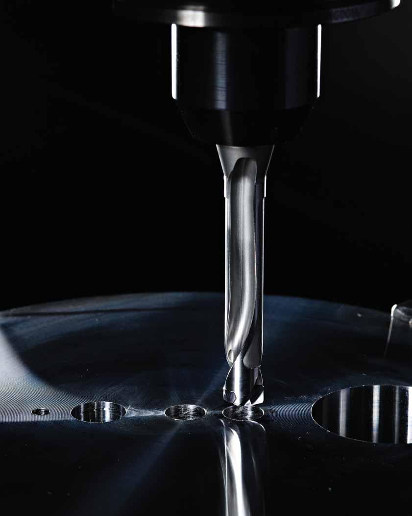
152

153 Modular Drills Introduction...S2 S3 TOP DRILL M1...S4 S30 Spade Blades...S32 S51 S1
154 Modular Drills Tool Selection Guide first choice alternate choice P M K N S H standard* standard range diameter range modular drills with internal coolant channel grade/series hole tolerance D1 mm min max D1 inch min max drilling depth L/D1 TOP DRILL M1 with front clamping mechanism TOP DRILL M1 inserts WU25PD** IT9 IT11 7,94 25, chamfering inserts TopSTEP SH WP20PH TopSTEP VG WP20PH 12,50 36, ,94 Ø<9,50 9,50 Ø<11,00 11,00 Ø<12, Ø< Ø< Ø<.4921 TOP DRILL M1 bodies 12,50 Ø<14, Ø< ,00 Ø<15, Ø<.6102 max 3 8 x D 15,50 Ø<16, Ø< ,50 Ø<20,50 20,50 Ø<21,00 21,00 Ø<25, Ø< Ø< Ø<1.023 * Apart from our standard drills, we can offer you a wide variety of special coating solutions and edge preparations to fulfill all your needs. If a specific drill is not suitable for your workpiece material, please contact your WIDIA distributor for available options. ** Grade WU25PD was previously named K20FTiAlN. S2
155 Modular Drills Tool Selection Guide Standard Product Engineered Solutions engineered solution range diameter range coolant drilling inclined exit countersinking counterboring 2 flute, 2 margin cooled corner chamfer plain shank H6 SCF Shanks D1 mm min max D1 inch min max max drilling depth page(s) TOP DRILL M1 with front clamping mechanism (continued) 7,94 27, S16 S21 12,50 36, S22 S23 7,94 Ø<9, Ø< x D 9,50 Ø<11, Ø< x D 11,00 Ø<12, Ø< x D 12,50 Ø<14, Ø< x D 14,00 Ø<15, Ø< x D S6 S14 15,50 Ø<16, Ø< x D 16,50 Ø<20, Ø< x D 20,50 Ø<21, Ø< x D 21,00 Ø<27, Ø< ,0mm S3

156 TOP DRILL M1 Modular Drill System With performance levels and metal removal rates comparable to that of solid carbide drills, WIDIA TOP DRILL M1 offers all the quality and performance you need in one versatile, economical package. The unique front clamping system enables inserts to be changed quickly, even inside the machine tool, saving setup time and manufacturing costs. TOP DRILL M1 The TDM1 platform offers UP(M) drill-point design in WU25PD grade a wide application range geometry, specially developed for cost-efficient drilling of steel, cast iron, and stainless steel. It covers diameter ranges from ( mm) within the standard offering in L/D ratios of 3, 5, and 8 x D. With its high level of performance, wide application range, and proven point geometry, TDM1 combines all of the economic benefits of a modular drilling system with the machining performance and hole quality to tackle even your most challenging operations. S4

157 UP Point Design Versatility and Productivity One insert style for all your work in steel, cast iron, and even stainless steels. Low cutting forces and excellent centering capabilities. Universal point style for consistent performance and excellent hole quality. Easy Insert Change No screws or clamps required. Insert blades can be changed with a simple wrench that comes with each holder. Disposable No reconditioning costs. Consistent performance from tip to tip. Eliminates number of tools waiting for reconditioning, thus avoiding hidden costs. Customization All intermediate diameters are quickly available as semi-standards. Multiple step drills available as customized solutions. New TopSTEP range of inserts offer extended chamfering and counterboring to your one-shot drilling solution. S5
158 Modular Drills TOP DRILL M1 Shanks Tool body shipped with insert wrench. Round Shank (No Flats) TOP DRILL M1 3 x D Straight Inch Modular Drills order number catalog number D1 D1 max D L L3 L4 max L5 LS insert blade seat size TDM0313R3SS W TDM0335R3SS W TDM0354R3SS W TDM0374R3SS W TDM0374R3SS W TDM0394R3SS W TDM0413R3SS W TDM0433R3SS W TDM0453R3SS W TDM0472R3SS W TDM0492R3SS W TDM0492R3SS W TDM0512R3SS W TDM0532R3SS W TDM0551R3SS W TDM0571R3SS W TDM0591R3SS W TDM0630R3SS W TDM0669R3SS W TDM0709R3SS W TDM0748R3SS W TDM0787R3SS W TDM0827R3SS W TDM0866R3SS W TDM0906R3SS W TDM0945R3SS W TDM0984R3SS W34 S6
159 Modular Drills TOP DRILL M1 Shanks Tool body shipped with insert wrench. Flanged Shank with Flats (SCF) TOP DRILL M1 3 x D Flanged Inch order number catalog number D1 D1 max D L1 L3 L4 max L5 LS insert blade seat size TDM0313R3SCF W TDM0335R3SCF W TDM0354R3SCF W TDM0374R3SCF W TDM0394R3SCF W TDM0413R3SCF W TDM0433R3SCF W TDM0453R3SCF W TDM0472R3SCF W TDM0492R3SCF W TDM0512R3SCF W TDM0532R3SCF W TDM0551R3SCF W TDM0571R3SCF W TDM0591R3SCF W TDM0630R3SCF W TDM0669R3SCF W TDM0709R3SCF W TDM0748R3SCF W TDM0787R3SCF W TDM0827R3SCF W TDM0866R3SCF W TDM0906R3SCF W TDM0945R3SCF W TDM0984R3SCF W34 Modular Drills S7
160 Modular Drills TOP DRILL M1 Shanks Tool body shipped with insert wrench. TOP DRILL M1 3 x D Flanged Metric Modular Drills order number catalog number D1 D1 max D L L1 L3 L4 max L5 LS insert blade seat size TDM080R3SCF12M 7,94 8, ,5 45 W TDM085R3SCF12M 8,50 8, ,6 45 W TDM090R3SCF12M 9,00 9, ,7 45 W TDM095R3SCF12M 9,50 9, ,8 45 W TDM100R3SCF16M 10,00 10, ,9 48 W TDM105R3SCF16M 10,50 10, ,0 48 W TDM110R3SCF16M 11,00 11, ,1 48 W TDM115R3SCF16M 11,50 11, ,2 48 W TDM120R3SCF16M 12,00 12, ,3 48 W TDM125R3SCF16M 12,50 12, ,4 48 W TDM130R3SCF16M 13,00 13, ,5 48 W TDM135R3SCF16M 13,50 13, ,6 48 W TDM140R3SCF16M 14,00 14, ,7 48 W TDM145R3SCF16M 14,50 14, ,8 48 W TDM150R3SCF20M 15,00 15, ,8 50 W TDM160R3SCF20M 16,00 16, ,0 50 W TDM170R3SCF20M 17,00 17, ,2 50 W TDM180R3SCF25M 18,00 18, ,4 56 W TDM190R3SCF25M 19,00 19, ,6 56 W TDM200R3SCF25M 20,00 20, ,8 56 W TDM210R3SCF25M 21,00 21, ,7 56 W TDM220R3SCF25M 22,00 22, ,9 56 W TDM230R3SCF25M 23,00 23, ,1 56 W TDM240R3SCF25M 24,00 24, ,2 56 W TDM250R3SCF25M 25,00 25, ,4 56 W34 S8
161 Modular Drills TOP DRILL M1 Shanks Tool body shipped with insert wrench. Round Shank (No Flats) TOP DRILL M1 5 x D Straight Inch order number catalog number D1 D1 max D L L3 L4 max L5 LS insert blade seat size TDM0313R5SS W TDM0335R5SS W TDM0354R5SS W TDM0374R5SS W TDM0374R5SS W TDM0394R5SS W TDM0413R5SS W TDM0433R5SS W TDM0453R5SS W TDM0472R5SS W TDM0492R5SS W TDM0492R5SS W TDM0512R5SS W TDM0532R5SS W TDM0551R5SS W TDM0571R5SS W TDM0591R5SS W TDM0630R5SS W TDM0669R5SS W TDM0709R5SS W TDM0748R5SS W TDM0787R5SS W TDM0827R5SS W TDM0866R5SS W TDM0906R5SS W TDM0945R5SS W TDM0984R5SS W34 Modular Drills S9
162 Modular Drills TOP DRILL M1 Shanks Tool body shipped with insert wrench. Flanged Shank with Flats (SCF) TOP DRILL M1 5 x D Flanged Inch Modular Drills order number catalog number D1 D1 max D L1 L3 L4 max L5 LS insert blade seat size TDM0313R5SCF W TDM0335R5SCF W TDM0354R5SCF W TDM0374R5SCF W TDM0394R5SCF W TDM0413R5SCF W TDM0433R5SCF W TDM0453R5SCF W TDM0472R5SCF W TDM0492R5SCF W TDM0512R5SCF W TDM0532R5SCF W TDM0551R5SCF W TDM0571R5SCF W TDM0591R5SCF W TDM0630R5SCF W TDM0669R5SCF W TDM0709R5SCF W TDM0748R5SCF W TDM0787R5SCF W TDM0827R5SCF W TDM0866R5SCF W TDM0906R5SCF W TDM0945R5SCF W TDM0984R5SCF W34 S10
163 Modular Drills TOP DRILL M1 Shanks Tool body shipped with insert wrench. TOP DRILL M1 5 x D Flanged Metric order number catalog number D1 D1 max D L L1 L3 L4 max L5 LS insert blade seat size TDM080R5SCF12M 7,94 8, ,5 45 W TDM085R5SCF12M 8,50 8, ,6 45 W TDM090R5SCF12M 9,00 9, ,7 45 W TDM095R5SCF12M 9,50 9, ,8 45 W TDM100R5SCF16M 10,00 10, ,9 48 W TDM105R5SCF16M 10,50 10, ,0 48 W TDM110R5SCF16M 11,00 11, ,1 48 W TDM115R5SCF16M 11,50 11, ,2 48 W TDM120R5SCF16M 12,00 12, ,3 48 W TDM125R5SCF16M 12,50 12, ,4 48 W TDM130R5SCF16M 13,00 13, ,5 48 W TDM135R5SCF16M 13,50 13, ,6 48 W TDM140R5SCF16M 14,00 14, ,7 48 W TDM145R5SCF16M 14,50 14, ,8 48 W TDM150R5SCF20M 15,00 15, ,8 50 W TDM160R5SCF20M 16,00 16, ,0 50 W TDM170R5SCF20M 17,00 17, ,2 50 W TDM180R5SCF25M 18,00 18, ,4 56 W TDM190R5SCF25M 19,00 19, ,6 56 W TDM200R5SCF25M 20,00 20, ,8 56 W TDM210R5SCF25M 21,00 21, ,7 56 W TDM220R5SCF25M 22,00 22, ,9 56 W TDM230R5SCF25M 23,00 23, ,1 56 W TDM240R5SCF25M 24,00 24, ,2 56 W TDM250R5SCF25M 25,00 25, ,4 56 W34 Modular Drills S11
164 Modular Drills TOP DRILL M1 Shanks Tool body shipped with insert wrench. Round Shank (No Flats) TOP DRILL M1 8 x D Straight Inch Modular Drills order number catalog number D1 D1 max D L L3 L4 max L5 LS insert blade seat size TDM0313R8SS W TDM0335R8SS W TDM0354R8SS W TDM0374R8SS W TDM0374R8SS W TDM0394R8SS W TDM0413R8SS W TDM0433R8SS W TDM0453R8SS W TDM0472R8SS W TDM0492R8SS W TDM0492R8SS W TDM0512R8SS W TDM0532R8SS W TDM0551R8SS W TDM0571R8SS W TDM0591R8SS W TDM0630R8SS W TDM0669R8SS W TDM0709R8SS W TDM0748R8SS W TDM0787R8SS W TDM0827R8SS W TDM0866R8SS W TDM0906R8SS W TDM0945R8SS W TDM0984R8SS W34 S12
165 Modular Drills TOP DRILL M1 Shanks Tool body shipped with insert wrench. Flanged Shank with Flats (SCF) TOP DRILL M1 8 x D Flanged Inch order number catalog number D1 D1 max D L1 L3 L4 max L5 LS insert blade seat size TDM0313R8SCF W TDM0335R8SCF W TDM0354R8SCF W TDM0374R8SCF W TDM0394R8SCF W TDM0413R8SCF W TDM0433R8SCF W TDM0453R8SCF W TDM0472R8SCF W TDM0492R8SCF W TDM0512R8SCF W TDM0532R8SCF W TDM0551R8SCF W TDM0571R8SCF W TDM0591R8SCF W TDM0630R8SCF W TDM0669R8SCF W TDM0709R8SCF W TDM0748R8SCF W TDM0787R8SCF W TDM0827R8SCF W TDM0866R8SCF W TDM0906R8SCF W TDM0945R8SCF W TDM0984R8SCF W34 Modular Drills S13
166 Modular Drills TOP DRILL M1 Shanks Tool body shipped with insert wrench. TOP DRILL M1 8 x D Flanged Metric Modular Drills order number catalog number D1 D1 max D L L1 L3 L4 max L5 LS insert blade seat size TDM080R8SCF12M 7,94 8, ,4 45 W TDM085R8SCF12M 8,50 8, ,5 45 W TDM090R8SCF12M 9,00 9, ,6 45 W TDM095R8SCF12M 9,50 9, ,7 45 W TDM100R8SCF16M 10,00 10, ,8 48 W TDM105R8SCF16M 10,50 10, ,9 48 W TDM110R8SCF16M 11,00 11, ,0 48 W TDM115R8SCF16M 11,50 11, ,1 48 W TDM120R8SCF16M 12,00 12, ,1 48 W TDM125R8SCF16M 12,50 12, ,2 48 W TDM130R8SCF16M 13,00 13, ,3 48 W TDM135R8SCF16M 13,50 13, ,4 48 W TDM140R8SCF16M 14,00 14, ,5 48 W TDM145R8SCF16M 14,50 14, ,6 48 W TDM150R8SCF20M 15,00 15, ,7 50 W TDM160R8SCF20M 16,00 16, ,8 50 W TDM170R8SCF20M 17,00 17, ,0 50 W TDM180R8SCF25M 18,00 18, ,2 56 W TDM190R8SCF25M 19,00 19, ,4 56 W TDM200R8SCF25M 20,00 20, ,6 56 W TDM210R8SCF25M 21,00 21, ,7 56 W TDM220R8SCF25M 22,00 22, ,9 56 W TDM230R8SCF25M 23,00 23, ,1 56 W TDM240R8SCF25M 24,00 24, ,2 56 W TDM250R8SCF25M 25,00 25, ,4 56 W34 S14
167 Notes

168 Modular Drills TOP DRILL M1 Inserts TOP DRILL M1 UP(M) first choice alternate choice K20FTiAlN grade WU25PD TiAlN D1 Modular Drills order # catalog # mm in seat size/series TDM0794UPM 7, W TDM0800UPM 8, W TDM0810UPM 8, W TDM0816UPM 8, W TDM0820UPM 8, W TDM0830UPM 8, W TDM0833UPM 8, W TDM0840UPM 8, W TDM0843UPM 8, W TDM0850UPM 8, W TDM0860UPM 8, W TDM0861UPM 8, W TDM0870UPM 8, W TDM0873UPM 8, W TDM0880UPM 8, W TDM0884UPM 8, W TDM0890UPM 8, W TDM0900UPM 9, W TDM0909UPM 9, W TDM0910UPM 9, W TDM0913UPM 9, W TDM0920UPM 9, W TDM0930UPM 9, W TDM0935UPM 9, W12 (continued) S16
169 Modular Drills TOP DRILL M1 Inserts (TOP DRILL M1 UP(M) continued) first choice alternate choice K20FTiAlN grade WU25PD TiAlN D1 order # catalog # mm in seat size/series TDM0940UPM 9, W TDM0950UPM 9, W TDM0953UPM 9, W TDM0956UPM 9, W TDM0958UPM 9, W TDM0960UPM 9, W TDM0970UPM 9, W TDM0980UPM 9, W TDM0990UPM 9, W TDM0992UPM 9, W TDM1000UPM 10, W TDM1002UPM 10, W TDM1008UPM 10, W TDM1010UPM 10, W TDM1020UPM 10, W TDM1026UPM 10, W TDM1030UPM 10, W TDM1032UPM 10, W TDM1040UPM 10, W TDM1049UPM 10, W TDM1050UPM 10, W TDM1060UPM 10, W TDM1070UPM 10, W TDM1072UPM 10, W TDM1080UPM 10, W TDM1090UPM 10, W TDM1100UPM 11, W TDM1110UPM 11, W TDM1111UPM 11, W TDM1120UPM 11, W TDM1130UPM 11, W TDM1140UPM 11, W TDM1150UPM 11, W TDM1151UPM 11, W TDM1160UPM 11, W TDM1161UPM 11, W TDM1170UPM 11, W TDM1180UPM 11, W TDM1190UPM 11, W TDM1191UPM 11, W17 (continued) Modular Drills S17
170 Modular Drills TOP DRILL M1 Inserts (TOP DRILL M1 UP(M) continued) first choice alternate choice K20FTiAlN grade WU25PD TiAlN D1 Modular Drills order # catalog # mm in seat size/series TDM1200UPM 12, W TDM1210UPM 12, W TDM1220UPM 12, W TDM1230UPM 12, W TDM1240UPM 12, W TDM1247UPM 12, W TDM1250UPM 12, W TDM1260UPM 12, W TDM1270UPM 12, W TDM1280UPM 12, W TDM1290UPM 12, W TDM1300UPM 13, W TDM1310UPM 13, W TDM1320UPM 13, W TDM1330UPM 13, W TDM1340UPM 13, W TDM1349UPM 13, W TDM1350UPM 13, W TDM1360UPM 13, W TDM1370UPM 13, W TDM1380UPM 13, W TDM1389UPM 13, W TDM1390UPM 13, W TDM1400UPM 14, W TDM1410UPM 14, W TDM1420UPM 14, W TDM1429UPM 14, W TDM1430UPM 14, W TDM1440UPM 14, W TDM1450UPM 14, W TDM1460UPM 14, W TDM1467UPM 14, W TDM1468UPM 14, W TDM1470UPM 14, W TDM1480UPM 14, W TDM1490UPM 14, W TDM1500UPM 15, W TDM1508UPM 15, W TDM1510UPM 15, W TDM1520UPM 15, W24 (continued) S18
171 Modular Drills TOP DRILL M1 Inserts (TOP DRILL M1 UP(M) continued) first choice alternate choice K20FTiAlN grade WU25PD TiAlN D1 order # catalog # mm in seat size/series TDM1530UPM 15, W TDM1540UPM 15, W TDM1548UPM 15, W TDM1550UPM 15, W TDM1560UPM 15, W TDM1570UPM 15, W TDM1580UPM 15, W TDM1588UPM 15, W TDM1600UPM 16, W TDM1603UPM 16, W TDM1608UPM 16, W TDM1610UPM 16, W TDM1618UPM 16, W TDM1620UPM 16, W TDM1627UPM 16, W TDM1630UPM 16, W TDM1640UPM 16, W TDM1650UPM 16, W TDM1660UPM 16, W TDM1667UPM 16, W TDM1670UPM 16, W TDM1680UPM 16, W TDM1687UPM 16, W TDM1690UPM 16, W TDM1700UPM 17, W TDM1707UPM 17, W TDM1710UPM 17, W TDM1720UPM 17, W TDM1730UPM 17, W TDM1740UPM 17, W TDM1746UPM 17, W TDM1750UPM 17, W TDM1760UPM 17, W TDM1770UPM 17, W TDM1780UPM 17, W TDM1786UPM 17, W TDM1790UPM 17, W TDM1800UPM 18, W TDM1810UPM 18, W TDM1820UPM 18, W27 (continued) Modular Drills S19
172 Modular Drills TOP DRILL M1 Inserts (TOP DRILL M1 UP(M) continued) first choice alternate choice K20FTiAlN grade WU25PD TiAlN D1 Modular Drills order # catalog # mm in seat size/series TDM1826UPM 18, W TDM1830UPM 18, W TDM1840UPM 18, W TDM1850UPM 18, W TDM1860UPM 18, W TDM1865UPM 18, W TDM1870UPM 18, W TDM1880UPM 18, W TDM1890UPM 18, W TDM1900UPM 19, W TDM1905UPM 19, W TDM1910UPM 19, W TDM1920UPM 19, W TDM1923UPM 19, W TDM1925UPM 19, W TDM1928UPM 19, W TDM1930UPM 19, W TDM1935UPM 19, W TDM1940UPM 19, W TDM1945UPM 19, W TDM1950UPM 19, W TDM1960UPM 19, W TDM1970UPM 19, W TDM1980UPM 19, W TDM1984UPM 19, W TDM1990UPM 19, W TDM2000UPM 20, W TDM2010UPM 20, W TDM2020UPM 20, W TDM2024UPM 20, W TDM2030UPM 20, W TDM2040UPM 20, W TDM2050UPM 20, W TDM2060UPM 20, W TDM2064UPM 20, W TDM2070UPM 20, W TDM2080UPM 20, W TDM2090UPM 20, W TDM2099UPM 20, W TDM2100UPM 21, W30 (continued) S20
173 Modular Drills TOP DRILL M1 Inserts (TOP DRILL M1 UP(M) continued) first choice alternate choice K20FTiAlN grade WU25PD TiAlN D1 order # catalog # mm in seat size/series TDM2144UPM 21, W TDM2150UPM 21, W TDM2200UPM 22, W TDM2223UPM 22, W TDM2245UPM 22, W TDM2250UPM 22, W TDM2300UPM 23, W TDM2350UPM 23, W TDM2381UPM 23, W TDM2400UPM 24, W TDM2450UPM 24, W TDM2461UPM 24, W TDM2500UPM 25, W TDM2540UPM 25, W TDM2550UPM 25, W TDM2568UPM 25, W TDM2581UPM 25, W TDM2599UPM 25, W34 Inch tolerance D1 tolerance k / > / > / > / Metric tolerance D1 tolerance k ,000/+0,022 > ,000/+0,027 > ,000/+0,027 > ,000/+0,033 Modular Drills S21

174 Modular Drills TOP DRILL M1 TopSTEP Chamfer and Counterboring Inserts Modular TOP DRILL M1 Step Drill Provides high productivity through high-feed, one-shot operations, and excellent tool life. Use TopSTEP VG and SH chamfer and counterboring inserts to create your specific TDM1 modular step drill. Create complex holes with countersinks, chamfers, or even both operations in one shot. Save time, achieve better cost, and run your complex drilling process with higher stability. Standard TOP DRILL M1 inserts. Standard TopSTEP SH counterboring insert. Standard TopSTEP VG chamfering insert. Modular Drills Made-to-Order TDM1 Toolholder Available within 3 4 weeks. Made custom to your needs. Let your WIDIA representative know about your specific needs. Use the Chamfer and Counterboring Order Planning pages to create and send us your request available online as well. S22

175 Modular Drills TOP DRILL M1 TopSTEP Chamfer and Counterboring Inserts TopSTEP VG Chamfering Inserts 45 chamfer angle with broad cutting edge. Hassle-free usage. Very stable and accurate positioning in pocket. Two times indexable. One universal insert size for a lot of applications. TopSTEP VG Chamfering Inserts first choice alternate choice P M K N S H W1 D1 S catalog number mm in mm in mm in VXGX , , , WP20PH TopSTEP SH Conterboring Inserts 90 insert can be positioned in alternative angles. Very good chip forming and surface quality. Two times indexable. Stocked standards in six insert sizes. TopSTEP SH Counterboring Inserts D D1 S R first choice alternate choice catalog number mm in mm in mm in mm in N N M SXHX060204R20 6, , , , SXHX070304R20 6, , , , SXHX060208R20 6, , , , SXHX070308R20 6, , , , SXHX090304R20 9, , , , SXHX090308R20 9, , , , P M K N S H WP20PH Modular Drills S23
176 Modular Drills Chamfering and Countersinking Order Planning Please utilize guide below to plan your TOP DRILL M1 modular step drill based on your needs and requirements. Please contact your distributor for a quote. Option 1 TOP DRILL M1 Drilling and Chamfering Overall Length [L] Drill Length [L1] Shank Diameter [D] Drill Diameter Min [D1] Drilling Depth [DD] Cutting Diameter 2 Angle Chamfering Depth [CD] Option 2 TOP DRILL M1 Drilling and Countersinking Overall Length [L] Drill Length [L1] Shank Diameter [D] Drill Diameter Min [D1] Drilling Depth [DD] Cut Diameter 23 [D23] Countersinking Depth [DD1] Cutting Diameter 2 Angle S24

177 Modular Drills Chamfering and Countersinking Order Planning Please utilize guide below to plan your TOP DRILL M1 modular step drill based on your needs and requirements. Please contact your distributor for a quote. Option 3 TOP DRILL M1 Drilling and Countersinking and Chamfering Overall Length [L] Drill Length [L1] Shank Diameter [D] Drill Diameter Min [D1] Drilling Depth [DD] Cut Diameter 23 [D23] Countersinking Depth [DD1] σ1 σ2 Cutting Diameter 2 Angle 1 Cutting Diameter 3 Angle 2 Chamfering depth [CD] If a more complex tool is required, we need your individual information to serve your specific needs. Please contact your WIDIA distributor for further guidance. S25
178 Modular Drills Application Data Victory TOP DRILL M1 UP(M) Geometry in WU25PD necessary coolant pressure (bar) (1 psi = bar) Coolant Pressure The diagram at left shows the coolant pressure as a function of the hole diameter. The higher the coolant pressure, the better the drilling result. Tool life and hole quality improve with increased coolant flow. favorable values Drilling on Inclined Surfaces When drilling on inclined or curved surfaces, use a 50% lower feed than the standard value. After the drill margins are fully engaged in the workpiece, increase the feed to the standard value (100%). Premachining is required on surfaces with inclination greater than 3. coolant pressure too low hole diameter d1 [mm] TOP DRILL M1 UP(M) WU25PD Speed and Feed Chart Metric P M K Cutting Speed vc Range m/min TOP DRILL M1 UP(M) WU25PD Speed and Feed Chart Inch Recommended Feed Rate Material Group min Starting Value max Tool Diameter (mm) 8,0 10,0 12,0 14,0 16,0 20,0 25, mm/r 0,11 0,20 0,13 0,25 0,14 0,31 0,17 0,39 0,19 0,45 0,25 0,48 0,30 0, mm/r 0,11 0,28 0,12 0,35 0,16 0,37 0,21 0,46 0,23 0,46 0,28 0,50 0,30 0, mm/r 0,11 0,28 0,12 0,35 0,16 0,37 0,21 0,46 0,23 0,46 0,28 0,50 0,30 0, mm/r 0,11 0,28 0,12 0,35 0,16 0,37 0,17 0,36 0,19 0,45 0,22 0,48 0,25 0, mm/r 0,10 0,20 0,10 0,23 0,10 0,25 0,14 0,29 0,16 0,32 0,18 0,36 0,22 0, mm/r 0,10 0,20 0,10 0,23 0,10 0,25 0,14 0,29 0,16 0,32 0,18 0,36 0,22 0, mm/r 0,06 0,22 0,08 0,23 0,09 0,24 0,10 0,25 0,11 0,26 0,13 0,28 0,13 0, mm/r 0,06 0,22 0,08 0,23 0,09 0,24 0,10 0,25 0,11 0,26 0,13 0,28 0,13 0, mm/r 0,06 0,22 0,08 0,23 0,09 0,24 0,10 0,25 0,11 0,26 0,13 0,28 0,13 0, mm/r 0,15 0,29 0,16 0,32 0,17 0,35 0,21 0,42 0,25 0,48 0,28 0,52 0,32 0, mm/r 0,15 0,29 0,16 0,30 0,17 0,33 0,21 0,41 0,25 0,48 0,28 0,52 0,32 0, mm/r 0,16 0,30 0,17 0,33 0,18 0,36 0,20 0,41 0,21 0,44 0,23 0,48 0,25 0,50 NOTE: Through coolant recommended for greater than 3 x D applications. P M K Cutting Speed vc Range SFM Recommended Feed Rate Material Group min Starting Value max Tool Diameter (inch) IPR IPR IPR IPR IPR IPR IPR IPR IPR IPR IPR IPR NOTE: Through coolant recommended for greater than 3 x D applications. S26
 Remove dust from insert using air blast. 2) Remove dust using air blast. 2) Set the wrench properly.* 3) Put insert into drill holder. (Use gloves to protect your hands.")
179 Modular Drills Application Data Victory TOP DRILL M1 How to attach inserts 1) Fix drill holder on arbor. For insert exchange, fix arbor on the machine or set on tool presetter. How to detach inserts 1) Remove dust from insert using air blast. 2) Remove dust using air blast. 2) Set the wrench properly.* 3) Put insert into drill holder. (Use gloves to protect your hands.) 3) Fit the wrench to insert slot. 4) Turn lightly in a clockwise direction. (Use gloves to protect your hands.) 4) Turn the wrench in a counterclockwise direction. 5) Set the wrench properly.* 5) Once lock is released, insert can be turned with fingers. (Use gloves to protect your hands.) 6) Make sure the wrench fits with the insert slot for the wrench. (Is the wrench unfixed from the slot?) 6) Remove insert. (Use gloves to protect your hands.) Slot for wrench 7) Slowly turn the wrench in a clockwise direction. *To order the TDM1 Wrench, please use order number and catalog number ) Complete. S27


 For Turning Machines Max.")
 For Machining Centers Concave Surface Not Recommended Max.")
180 Modular Drills Application Data Victory TOP DRILL M1 Cautions Coolant 1) Internal coolant is recommended. Application Recommendation Workpiece Shape Flat Face Recommended 2) In case of external coolant, cutting depth must be 3 x D or less. Stacked Plates Recommended 3) Dry cutting is not recommended. Limited applicability in cast iron materials, MQL strongly recommended. Inclined Surface >3 Not Recommended Usage Precautions Core deviation Half Cylindrical Not Recommended 1) For Turning Machines Max. 0,02mm Hole Expansion Not Recommended Set deviation amount under 0,02mm between workpiece and drill. 2) For Machining Centers Concave Surface Not Recommended Max. 0,02mm Pipe Material Not Recommended Do not use any arbor with a damaged attachment surface. Center of arbor deviation must be within 0,02mm. Cored Hole Not Recommended S28
![Modular Drills Application Data Victory TOP DRILL M1 Steel Torque Inch Metric 70 100 60 90 80 Md [ft.lb.] Torque 50 40 30 20 10 0 fz = 0.018 fz = 0.014 fz = 0.010 fz = 0.006 0.315 0.394 0.472 0.551 0.](/docs-images/87/95402916/images/181-0.jpg "630 0.709 0.787 0.866 0.945 1.")
181 Modular Drills Application Data Victory TOP DRILL M1 Steel Torque Inch Metric Md [ft.lb.] Torque fz = fz = fz = fz = Md [Nm] Torque fz = 0,45 fz = 0,35 fz = 0,25 fz = 0, Drill Diameter D1 [in] Drill Diameter D1 [mm] Power Inch Metric Ps [PS] Drive Power fz = fz = fz = fz = Ps [kw] Drive Power fz = 0,15 fz = 0,25 fz = 0,35 fz = 0, Drill Diameter D1 [in] Drill Diameter D1 [mm] Feed Force Inch Metric Ff [lb] Feed Force fz = fz = fz = fz = Ff [kn] Feed Force fz = 0,15 fz = 0,25 fz = 0,35 fz = 0, Drill Diameter D1 [in] Drill Diameter D1 [mm] S29
182 Modular Drills Application Data Victory TOP DRILL M1 Cast Iron Torque Inch Metric Md [ft.lb.] Torque fz = fz = fz = fz = Md [Nm] Torque fz = 0,50 fz = 0,40 fz = 0,30 fz = 0, Drill Diameter D1 [in] Drill Diameter D1 [mm] Power Inch Metric Ps [PS] Drive Power fz = fz = fz = fz = Ps [kw] Drive Power fz = 0,15 fz = 0,25 fz = 0,35 fz = 0, Drill Diameter D1 [in] Drill Diameter D1 [mm] Feed Force Inch Metric Ff [lb] Feed Force fz = fz = fz = fz = Ff [kn] Feed Force fz = 0,15 fz = 0,25 fz = 0,35 fz = 0, Drill Diameter D1 [in] Drill Diameter D1 [mm] S30
183 Notes

184 WIDIA-Metcut Spade Blades A compliment to TOP DRILL M1 WIDIA provides a comprehensive line of spade blades from " (8 114mm) to cover a wide range of machining environments and materials. Spade Blades Fast penetration rates, less downtime, and lower variability. Interchangeable with other conventional spade blade holders. Improved surface finish eliminates subsequent hole finishing operations. Standard and special drill body/holder offering, including step drill and porting tool configurations. Intermediate diameters and specific toolholder length quickly available upon request. WIDIA-Metcut spade blades are great choices for: Universal application for most plain and alloyed steel applications as well as for cast iron and stainless steels. Machining environments where rigidity, coolant supply, or speed and feed rates are limiting factors. Short run manufacturing and prototyping environments. Especially when dealing with larger diameters and deeper holes. S32
185 Application Information T-15 HSS spade blades are recommended: For providing straighter and more consistent holes with superior surface finishes than can be produced using either HSS twist drills or carbide indexable drills. When rigidity of the machine or the fixture requires a more forgiving, durable and tougher tool; T-15 steel possesses a higher transverse rupture strength and is more impact-resistant than comparable carbide spade blades and/or carbide indexable drills. In applications requiring hole depths up through 15x to 20x diameter; pecking may be required for depths above 7x diameter for some materials. As a cost-effective alternative to carbide indexable drills since T-15 steel spade blades operate at comparable penetration rates to single-effective indexable drills in materials <35 Rc, and one spade blade holder accommodates multiple diameter blades. Spade Blade Holders Generally can accommodate a range of blade sizes up to times the smallest blade size. It is therefore possible to cover the entire range of hole sizes with just a few spade drill holders. Contrast this with the inventories required for indexable drills and steel taper shank drills. S33
186 Spade Blades T-15 HSS TiAlN TiN Seat Size Z TiAlN TiN first choice alternate choice D1 L S D1 L S order # catalog # order # catalog # mm in mm in mm in FZ-0438A 11, , , FZ-0472A 12, , , FZ-0484A 12, , , FZ-0492A 12, , , FZ-0500A FZ-0500T 12, , , NOTE: Toolholders available upon request as an Engineered Solution. Modular Drills S34
187 Spade Blades T-15 HSS TiAlN TiN Seat Size 0 TiAlN TiN first choice alternate choice D1 L S D1 L S order # catalog # order # catalog # mm in mm in mm in F0-0509A 12, , , F0-0512T 13, , , F0-0516A 13, , , F0-0531A F0-0531T 13, , , F0-0547A F0-0547T 13, , , F0-0551A F0-0551T 14, , , F0-0563A F0-0563T 14, , , F0-0571A 14, , , F0-0578A F0-0578T 14, , , F0-0591A F0-0591T 15, , , F0-0594A F0-0594T 15, , , F0-0609A F0-0609T 15, , , F0-0610A 15, , , F0-0625A F0-0625T 15, , , F0-0630A F0-0630T 16, , , F0-0641A F0-0641T 16, , , F0-0650T 16, , , F0-0656A F0-0656T 16, , , F0-0669A 17, , , F0-0672A F0-0672T 17, , , F0-0688A F0-0688T 17, , , F0-0689A F0-0689T 17, , , Modular Drills NOTE: Toolholders available upon request as an Engineered Solution. S35
188 Spade Blades T-15 HSS TiAlN TiN Seat Size 1 TiAlN TiN first choice alternate choice D1 L S D1 L S Modular Drills order # catalog # order # catalog # mm in mm in mm in F1-0703A F1-0703T 17, , , F1-0709A F1-0709T 18, , , F1-0719T 18, , , F1-0734A F1-0734T 18, , , F1-0748A F1-0748T 19, , , F1-0750A F1-0750T 19, , , F1-0756T 19, , , F1-0766A F1-0766T 19, , , F1-0768T 19, , , F1-0781A F1-0781T 19, , , F1-0787A F1-0787T 20, , , F1-0797T 20, , , F1-0806A 20, , , F1-0807A F1-0807T 20, , , F1-0813A F1-0813T 20, , , F1-0827A F1-0827T 21, , , F1-0828A F1-0828T 21, , , F1-0844T 21, , , F1-0859A F1-0859T 21, , , F1-0866A F1-0866T 22, , , F1-0875A F1-0875T 22, , , F1-0891A F1-0891T 22, , , F1-0906A F1-0906T 23, , , F1-0922A F1-0922T 23, , , F1-0938A F1-0938T 23, , , F1-0945A F1-0945T 24, , , F1-0953A F1-0953T 24, , , F1-0960T 24, , , NOTE: Toolholders available upon request as an Engineered Solution. S36
189 Spade Blades T-15 HSS TiAlN TiN Seat Size 2 TiAlN TiN first choice alternate choice D1 L S D1 L S order # catalog # order # catalog # mm in mm in mm in F2-0969T 24, , , F2-0984A F2-0984T 25, , , F2-1000A F2-1000T 25, , , F2-1003A 25, , , F2-1016A F2-1016T 25, , , F2-1024A F2-1024T 26, , , F2-1031A F2-1031T 26, , , F2-1047A F2-1047T 26, , , F2-1063A F2-1063T 26, , , F2-1078A F2-1078T 27, , , F2-1094A F2-1094T 27, , , F2-1102A F2-1102T 28, , , F2-1109T 28, , , F2-1125A F2-1125T 28, , , F2-1141A 28, , , F2-1142A 29, , , F2-1156A F2-1156T 29, , , F2-1172T 29, , , F2-1181A F2-1181T 30, , , F2-1188A F2-1188T 30, , , F2-1203T 30, , , F2-1219A F2-1219T 30, , , F2-1221A 31, , , F2-1231A 31, , , F2-1234T 31, , , F2-1250A F2-1250T 31, , , F2-1254T 31, , , F2-1260A F2-1260T 32, , , NOTE: Toolholders available upon request as an Engineered Solution. (continued) Modular Drills S37
190 Spade Blades T-15 HSS (Seat Size 2 continued) TiAlN TiN first choice alternate choice D1 L S D1 L S order # catalog # order # catalog # mm in mm in mm in F2-1266A F2-1266T 32, , , F2-1281T 32, , , F2-1299A 33, , , F2-1313A F2-1313T 33, , , F2-1328T 33, , , F2-1339A 34, , , F2-1344A F2-1344T 34, , , F2-1359T 34, , , F2-1375A F2-1375T 34, , , F2-1378A 35, , , F4-2166A 55, , , NOTE: Toolholders available upon request as an Engineered Solution. Modular Drills S38
191 Spade Blades T-15 HSS TiAlN TiN Seat Size 3 TiAlN TiN first choice alternate choice D1 L S D1 L S order # catalog # order # catalog # mm in mm in mm in F3-1391T 35, , , F3-1406A F3-1406T 35, , , F3-1417A F3-1417T 36, , , F3-1438A F3-1438T 36, , , F3-1457A F3-1457T 37, , , F3-1469A F3-1469T 37, , , F3-1484T 37, , , F3-1496A 38, , , F3-1500A F3-1500T 38, , , F3-1516T 38, , , F3-1531T 38, , , F3-1535A 39, , , F3-1563A F3-1563T 39, , , F3-1575A F3-1575T 40, , , F3-1594T 40, , , F3-1614A 41, , , F3-1625A F3-1625T 41, , , F3-1654A 42, , , F3-1656T 42, , , F3-1688A F3-1688T 42, , , F3-1693T 43, , , F3-1719A F3-1719T 43, , , F3-1732A 44, , , F3-1750A F3-1750T 44, , , F3-1766T 44, , , F3-1772A F3-1772T 45, , , F3-1781T 45, , , F3-1811A 46, , , F3-1813A F3-1813T 46, , , F3-1844T 46, , , F3-1850T 47, , , F3-1875A F3-1875T 47, , , NOTE: Toolholders available upon request as an Engineered Solution. Modular Drills S39
192 Spade Blades T-15 HSS TiAlN TiN Seat Size 4 TiAlN TiN first choice alternate choice D1 L S D1 L S Modular Drills order # catalog # order # catalog # mm in mm in mm in F4-1880T 47, , , F4-1890A F4-1890T 48, , , F4-1906A F4-1906T 48, , , F4-1929A 49, , , F4-1938A F4-1938T 49, , , F4-1969A F4-1969T 50, , , F4-2000A F4-2000T 50, , , F4-2008T 51, , , F4-2016T 51, , , F4-2031A F4-2031T 51, , , F4-2047A F4-2047T 52, , , F4-2063A F4-2063T 52, , , F4-2087A 53, , , F4-2094T 53, , , F4-2125A F4-2125T 53, , , F4-2126A 54, , , F4-2156T 54, , , F4-2188T 55, , , F4-2205A 56, , , F4-2219A F4-2219T 56, , , F4-2244A 57, , , F4-2250A F4-2250T 57, , , F4-2281T 57, , , F4-2284A 58, , , F4-2313A F4-2313T 58, , , F4-2323A 59, , , F4-2344T 59, , , F4-2362T 60, , , (continued) S40
193 Spade Blades T-15 HSS (Seat Size 4 continued) TiAlN TiN first choice alternate choice D1 L S D1 L S order # catalog # order # catalog # mm in mm in mm in F4-2375A F4-2375T 60, , , F4-2438A F4-2438T 61, , , F4-2441A 62, , , F4-2469A 62, , , F4-2480T 63, , , F4-2500A F4-2500T 63, , , F4-2531T 64, , , F4-2559A 65, , , F4-2563A F4-2563T 65, , , NOTE: Toolholders available upon request as an Engineered Solution. Modular Drills S41
194 Spade Blades T-15 HSS TiAlN TiN Seat Size 5 TiAlN TiN first choice alternate choice D1 L S D1 L S order # catalog # order # catalog # mm in mm in mm in F5-2500T 63, , , F5-2563A F5-2563T 65, , , F5-2625T 66, , , F5-2656T 67, , , F5-2677A 68, , , F5-2719T 69, , , F5-2750A F5-2750T 69, , , F5-2756A 70, , , F5-2813A 71, , , F5-2875A F5-2875T 73, , , F5-2938T 74, , , F5-2969A F5-2969T 75, , , F5-3000A F5-3000T 76, , , NOTE: Toolholders available upon request as an Engineered Solution. Modular Drills Seat Size 6 first choice alternate choice D1 L S TiAlN TiN D1 L S order # catalog # order # catalog # mm in mm in mm in F6-3063A F6-3063T 77, , , F6-3071A 78, , , F6-3125A 79, , , F6-3150A 80, , , F6-3188T 80, , , F6-3250T 82, , , F6-3375T 85, , , F6-3438T 87, , , F6-3500T 88, , , NOTE: Toolholders available upon request as an Engineered Solution. S42
195 Spade Blades T-15 HSS TiN TiAlN Seat Size 7 TiAlN TiN first choice alternate choice D1 L S D1 L S order # catalog # order # catalog # mm in mm in mm in F7-3543T 90, , , F7-3563T 90, , , F7-3688T 93, , , F7-3938T 96, , , F7-3813A 96, , , F7-4000A 101, , , NOTE: Toolholders available upon request as an Engineered Solution. Modular Drills S43
196 Spade Blades Application Data HSS Spade Blades HSS Spade Blades Speed and Feed Chart Inch Modular Drills Material Group P M 1 K 1,2 N 1 S 1 Grade Feed (mm/rev) Hardness BHN TiN TiAlN Y & Z (9.5 to 12.7) 0 (13 to 17.5) 1 ( ) 2 ( ) 3 ( ) 4 ( ) ( ) ( ) S44
197 Spade Blades Application Data HSS Spade Blades HSS Spade Blades Speed and Feed Chart Metric Material Group P M 1 K 1,2 N 1 S 1 Grade Feed (mm/rev) Hardness BHN TiN TiAlN Y & Z (9.5 to 12.7) 0 (13 to 17.5) 1 ( ) 2 ( ) 3 ( ) 4 ( ) ( ) ( ) ,18 0,23 0,30 0,38 0,48 0,58 0,64 0, ,15 0,23 0,30 0,38 0,48 0,58 0,61 0, ,13 0,20 0,25 0,36 0,46 0,53 0,58 0, ,13 0,20 0,25 0,36 0,46 0,53 0,58 0, ,20 0,28 0,36 0,43 0,53 0,64 0,66 0, ,18 0,25 0,33 0,41 0,51 0,58 0,61 0, ,15 0,25 0,33 0,41 0,51 0,58 0,61 0, ,15 0,23 0,30 0,38 0,48 0,58 0,64 0, ,13 0,20 0,25 0,36 0,46 0,53 0,58 0, ,13 0,20 0,25 0,36 0,46 0,53 0,56 0, ,10 0,18 0,23 0,30 0,41 0,48 0,53 0, ,18 0,23 0,28 0,36 0,46 0,53 0,58 0, ,15 0,20 0,25 0,36 0,43 0,48 0,53 0, ,13 0,18 0,25 0,33 0,43 0,48 0,51 0, ,10 0,15 0,23 0,30 0,38 0,43 0,46 0, ,08 0,15 0,23 0,30 0,38 0,43 0,46 0, ,13 0,18 0,23 0,25 0,36 0,41 0,46 0, ,10 0,18 0,23 0,25 0,36 0,41 0,46 0, ,08 0,15 0,20 0,23 0,30 0,36 0,41 0, ,15 0,25 0,30 0,36 0,46 0,53 0,56 0, ,13 0,23 0,25 0,30 0,41 0,48 0,51 0, ,10 0,20 0,23 0,25 0,36 0,43 0,46 0, ,13 0,15 0,20 0,25 0,30 0,38 0,41 0, ,10 0,15 0,20 0,25 0,30 0,38 0,41 0, ,10 0,13 0,18 0,20 0,25 0,33 0,36 0, ,08 0,10 0,15 0,18 0,23 0,30 0,33 0, ,15 0,20 0,23 0,28 0,36 0,41 0,46 0, ,13 0,18 0,20 0,25 0,30 0,36 0,41 0, ,13 0,15 0,18 0,23 0,28 0,33 0,38 0, ,20 0,30 0,41 0,51 0,61 0,69 0,74 0, ,18 0,28 0,36 0,46 0,56 0,64 0,69 0, ,15 0,23 0,30 0,41 0,46 0,53 0,58 0, ,13 0,18 0,23 0,30 0,36 0,43 0,48 0, ,10 0,15 0,18 0,23 0,30 0,36 0,41 0, ,18 0,30 0,38 0,48 0,53 0,61 0,64 0, ,20 0,33 0,41 0,51 0,56 0,64 0,66 0, ,13 0,18 0,20 0,25 0,30 0,38 0,41 0, ,10 0,15 0,18 0,20 0,25 0,30 0,33 0, ,10 0,13 0,15 0,18 0,23 0,28 0,30 0,33 Modular Drills S45
198 Spade Blade Holders Straight Shank Straight Flute Holders Inch Short D1 D1 max short mm in mm in L L1 L4 max LS D seat size CS insert screw Torx wrench 7SZSS 11, , Z 1/8-27 NPT S0SS 12, , /8-27 NPT S0.5SS 15, , /8-27 NPT S1SS 17, , /4-18 NPT S1.5SS 21, , /4-18 NPT S2SS 24, , /4-18 NPT S2.5SS 30, , /4-18 NPT S3SS 35, , /4-18 NPT S4SS 47, , /4-18 NPT S5SS 63, , /4-18 NPT Straight Flute Holders Inch Medium Modular Drills D1 D1 max medium mm in mm in L L1 L4 max LS D seat size CS insert screw Torx wrench 7SZSM 11, , Z 1/8-27 NPT S0SM 12, , /8-27 NPT S0.5SM 15, , /8-27 NPT S1SM 17, , /4-18 NPT S1.5SM 21, , /4-18 NPT S2SM 24, , /4-18 NPT S2.5SM 30, , /4-18 NPT S3SM 35, , /4-18 NPT S4SM 47, , /4-18 NPT S5SM 63, , /4-18 NPT S7SM 88, , /4-18 NPT S46
199 Spade Blade Holders Straight Shank Straight Flute Holders Inch Long D1 D1 max long mm in mm in L L1 L4 max LS D seat size CS insert screw Torx wrench 7SZSL 11, , Z 1/8-27 NPT S0SL 12, , /8-27 NPT S0.5SL 15, , /8-27 NPT S1SL 17, , /4-18 NPT S2SL 24, , /4-18 NPT S3SL 35, , /4-18 NPT S4SL 47, , /4-18 NPT S7SL 88, , /4-18 NPT Straight Flute Holders Inch Extra Long D1 D1 max extra long mm in mm in L L1 L4 max LS D seat size CS insert screw Torx wrench 7S0SE 12, , /8-27 NPT S0.5SE 15, , /8-27 NPT S1SE 17, , /4-18 NPT S1.5SE 21, , /4-18 NPT S2SE 24, , /4-18 NPT S3SE 35, , /4-18 NPT S4SE 47, , /4-18 NPT Modular Drills S47
200 Spade Blade Holders Straight Shank Straight Flute Holders Metric Short D1 D1 max short mm in mm in L L1 L4 max LS D seat size insert screw Torx wrench 8S0SS 13, , FT7 8S1SS 17, , FT8 8S2SS 24, , FT15 8S4SS 48, , FT20 Straight Flute Holders Metric Medium D1 D1 max medium mm in mm in L L1 L4 max LS D seat size insert screw Torx wrench 8S0SM 13, , FT7 8S1SM 17, , FT8 8S2SM 24, , FT15 8S3SM 35, , FT20 Modular Drills S48
201 Spade Blade Holders Straight Shank Straight Flute Holders Metric Long D1 D1 max long mm in mm in L L1 L4 max LS D seat size CS insert screw Torx wrench 8S0SL 12, , R1/ FT7 8S1SL 17, , FT8 8S2SL 24, , FT15 Straight Flute Holders Metric Extra Long D1 D1 max seat insert Torx extra long mm in mm in L L1 L4 max LS D size screw wrench 8S2SE 24, , FT15 Modular Drills S49
202 Spade Blade Holders Taper Shank Through coolant must be used with spade drills depths greater than 1 x D. Direct spindle cooling is preferable when using WIDIA Spade Blades. If spindle cooling is unavailable, then coolant glands or inducers should be used to provide through coolant capability. Our holders provide both options; please find available coolant glants below. Straight Flute Holders Short D1 D1 max short mm in mm in L L1 L4 max LS CSMS system size seat size CS insert screw Torx wrench 7SZTS 11, , Z S1TS 17, , / S2TS 24, , / S2.5TS 30, , / S3TS 35, , / S4TS 47, , / S5TS 63, , / NOTE: CSMS = Morse taper size. Modular Drills Straight Flute Holders Medium D1 D1 max medium mm in mm in L L1 L4 max LS CSMS system size seat size CS insert screw Torx wrench 7S0TM 12, , S1TM 17, , / S1.5TM 21, , / S2TM 24, , / S2.5TM-4MT 30, , / S3TM 35, , / S4TM 47, , / S5TM 63, , / S7TM 88, , / NOTE: CSMS = Morse taper size. S50
203 Spade Blade Holders Taper Shank Straight Flute Holders Long D1 D1 max long mm in mm in L L1 L4 max LS CSMS system size seat size CS insert screw Torx wrench 7SZTL 11, , Z S0TL 12, , S1TL 17, , / S2TL 24, , / S3TL 35, , / S4TL 47, , / S5TL 63, , / S7TL 88, , / NOTE: CSMS = Morse taper size. Straight Flute Holders Extra Long D1 D1 max extra long mm in mm in L L1 L4 max LS CSMS system size seat size CS insert screw Torx wrench 7S0TE 12, , S0.5TE 15, , S2TE 24, , / NOTE: CSMS = Morse taper size. Modular Drills S51
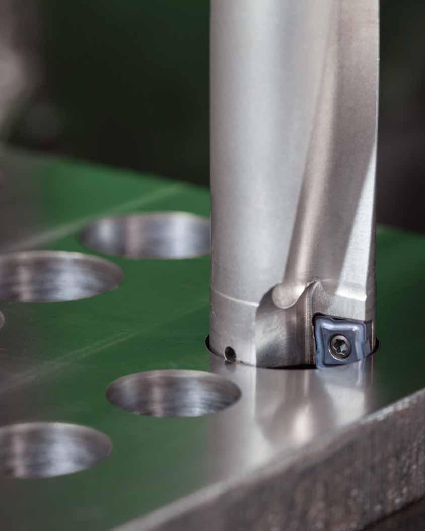
204

205 Indexable Drills Introduction... T2 T3 Top Cut 4... T4 T60 T1
206 Tool Selection Guide for Indexable Drills standard standard range customized solution range first choice diameter range diameter range alternate choice D1 mm D1 in D1 mm D1 inch hole drilling P M K N S H tolerance min max min max depth L/D1 min max min max drilling depth Top Cut 4 Indexable Drill Body Short Hole Drilling IT x D 3 x D 4 x D 5 x D x D 2) In regard to insert and drill coatings, anything is possible. If a specific insert or drill is not suitable for your workpiece material, please contact our Engineered Solutions Department for an offer about special coatings and edge preparations. *Except for L/D 5 x D. 1) Other shank styles available as customized solution. 2) Dependent on the application, up to 6 x D is possible. T2
207 Tool Selection Guide for Indexable Drills standard capabilities 1) standard customized solution capabilities Coolant page(s) * T8 T31 T3
208 WIDIA Top Cut 4 New Generation Indexable Drilling System The new WIDIA Top Cut 4 (TC4) portfolio is a broad offering for customers looking for a versatile indexable drilling platform. The newly developed TC4 features improved centering capabilities and inserts with four cutting edges for both pocket seats (central and periphery). This, in combination with the renowned WIDIA grade technology, leads to outstanding flexibility and efficiency. The TC4 platform offers three easy-to-select grades and two geometries applicable for steel, cast iron, and stainless steel materials. It covers the diameter range from " (12 68mm) within the standard offering in L/D ratios of 2 5 x D. TOP CUT 4 One Comprehensive Platform Standard diameter range covering " (12 68mm) in 2 x D, 3 x D, 4 x D, and 5 x D. Four real cutting edges each for entire platform. Eight insert sizes to cover complete diameter range. Easy to Apply No risk of mixing up inner and outer insert due to clear visual differences. Easy-to-change inserts, laser marked with geometries and grades. Easy-to-use nomenclature guide enabling the tool body and the related insert selection to avoid order failures. T4

209 Highly Versatile Breadth of application capabilities include through and cross holes, inclined entry and exit opportunity, 45º corner, half cylindrical, concave, or chain drilling. Various geometries and grades available. Highest Performance 2x four true cutting edges. Cutting edge profile of central and periphery insert work together, leading to high stabilization of the drill, preventing drifting of the tool even on irregular surfaces. X-offset design to adjust diameter size on turning machines and optimize tolerances on machining centers. Apply where speed and economy are prime considerations. Three grades to achieve higher tool life at accelerated speeds: WU25CH grade for highest metal removal rate in general applications. WU40PH grade for high toughness demands. WPK10CH grade for high-speed applications. T5
210 Indexable Drills Top Cut 4 Catalog Numbering System Metric Body The guide below provides an example of how to select the Top Cut 4 tool body and accompanying inserts for a stable steel drilling application. TCF 250 R 3 SL 32 M D Tool Family Top Cut 4 Diameter Metric = 3 digits (e.g. 250 = 25mm) Inch = 4 digits (e.g = 2.5") Right-Hand Cutting Length Diameter Ratio L/D = 3 x D Shank Style SL = Side Lock Adapter Shank Size Metric Insert Size Inch Body TCF 1000 R 3 SSF 100 D Tool Family Top Cut 4 Diameter Metric = 3 digits (e.g. 250 = 25mm) Inch = 4 digits (e.g = 2.5") Right-Hand Cutting Length Diameter Ratio L/D = 3 x D Shank Style SSF = Straight Shank Flange Shank Size Insert Size Periphery Insert TCF D P V34 WU25CH Tool Family Top Cut 4 Size In-Circle D1 Insert Thickness Insert Corner Radius Insert Size Insert Positioning C = Central P = Periphery Insert Geometry Grade Insert Geometry V34 for steel or cast iron or V36 for stainless steel and long chipping steel. Insert Guide for Grades W U 25 C H W U 40 P H W PK 10 C H WIDIA Material Range U = Universal P = Steel K = Cast Iron Toughness Range Choose high numbers for toughness in stable conditions, low numbers for high wear resistance at continuous cuts. Coating P = PVD C = CVD Application H = Holemaking T6
211 Indexable Drills Grades and Grade Descriptions Coatings provide high-speed capability and are engineered for finishing to light roughing. P M K N S H Steel Stainless Steel Cast Iron Non-Ferrous High-Temp Alloys Hardened Materials wear resistance toughness Coating Grade Description WPK10CH TiCN-Al 2 O 3 Composition: With an advanced CVD TiCN-Al 2 O 3 coating combined with a cobalt-enriched carbide substrate, this grade offers a balanced combination of deformation-resistance and edge toughness. Application: Offers outstanding abrasion and crater wear resistance for high-speed machining of steels and cast irons. Use for very high cutting speeds with low to medium feed rates. P K Grade WU25CH TiCN-Al 2 O 3 Composition: Advanced CVD TiCN-Al 2 O 3 coating together with a newly engineered tough carbide substrate. Ensures adequate deformation resistance and excellent edge strength and offers very good wear resistance over a wide range of machining conditions. Application: A high productivity grade with high speeds and feeds. First choice for high productivity with very good reliability in steels, stainless steels, and cast iron rates. P M K P WU40PH Composition: With a multilayered PVD TiN-TiAlN coating and a tough substrate, this grade withstands interruptions and provides high wear resistance for long tool life. Application: First choice for high reliability in most materials. This grade should be used at medium speeds and high feeds due to sharper edges and as a grade for hightoughness applications. It covers steel, stainless steel, cast iron, and high-temp alloys under certain conditions. M K TiCN-Al 2 O 3 P K WPK10CH wear resistance P M K WU25CH P WPK10CH: High-Speed Grade M K WU40PH WU25CH: High Metal Removal Rate Grade WU40PH: High Toughness Grade toughness T7
212 Indexable Drills Top Cut 4 Shanks For information on CF, LS, and CS, see the table on page T9. Top Cut 4 Drill Inch 2 x D SSF Shanks Indexable Drills order number catalog number D1 D1 max D L1 L4 max L5 insert size periphery insert center insert TCF0473R2SSF075A A TCF040204AP TCF040203AC TCF0500R2SSF075A A TCF040204AP TCF040203AC TCF0531R2SSF075A A TCF040204AP TCF040203AC TCF0563R2SSF075B B TCF050204BP TCF060203BC TCF0594R2SSF075B B TCF050204BP TCF060203BC TCF0625R2SSF075B B TCF050204BP TCF060203BC TCF0656R2SSF075B B TCF050204BP TCF060203BC TCF0688R2SSF075B B TCF050204BP TCF060203BC TCF0703R2SSF075B B TCF050204BP TCF060203BC TCF0719R2SSF075B B TCF050204BP TCF060203BC TCF0734R2SSF075B B TCF050204BP TCF060203BC TCF0750R2SSF100C C TCF070306CP TCF070304CC TCF0781R2SSF100C C TCF070306CP TCF070304CC TCF0813R2SSF100C C TCF070306CP TCF070304CC TCF0844R2SSF100C C TCF070306CP TCF070304CC TCF0875R2SSF100C C TCF070306CP TCF070304CC TCF0906R2SSF100C C TCF070306CP TCF070304CC TCF0938R2SSF100C C TCF070306CP TCF070304CC TCF0969R2SSF100D D TCF080308DP TCF090305DC TCF0984R2SSF100D D TCF080308DP TCF090305DC TCF1000R2SSF100D D TCF080308DP TCF090305DC TCF1031R2SSF125D D TCF080308DP TCF090305DC TCF1063R2SSF125D D TCF080308DP TCF090305DC TCF1094R2SSF125D D TCF080308DP TCF090305DC TCF1125R2SSF125D D TCF080308DP TCF090305DC TCF1156R2SSF125D D TCF080308DP TCF090305DC TCF1188R2SSF125E E TCF100408EP TCF120405EC TCF1210R2SSF125E E TCF100408EP TCF120405EC TCF1219R2SSF125E E TCF100408EP TCF120405EC TCF1250R2SSF125E E TCF100408EP TCF120405EC TCF1280R2SSF125E E TCF100408EP TCF120405EC TCF1313R2SSF125E E TCF100408EP TCF120405EC TCF1375R2SSF125E E TCF100408EP TCF120405EC TCF1406R2SSF150E E TCF100408EP TCF120405EC TCF1438R2SSF150E E TCF100408EP TCF120405EC TCF1469R2SSF150F F TCF120412FP TCF150406FC (continued) T8
213 Indexable Drills Top Cut 4 Shanks (Top Cut 4 Drill Inch 2 x D SSF Shanks continued) order number catalog number D1 D1 max D L1 L4 max L5 insert size periphery insert center insert TCF1500R2SSF150F F TCF120412FP TCF150406FC TCF1531R2SSF150F F TCF120412FP TCF150406FC TCF1563R2SSF150F F TCF120412FP TCF150406FC TCF1625R2SSF150F F TCF120412FP TCF150406FC TCF1656R2SSF150F F TCF120412FP TCF150406FC TCF1688R2SSF150F F TCF120412FP TCF150406FC TCF1750R2SSF150F F TCF120412FP TCF150406FC TCF1813R2SSF150G G TCF150512GP TCF180508GC TCF1875R2SSF150G G TCF150512GP TCF180508GC TCF1938R2SSF150G G TCF150512GP TCF180508GC TCF2000R2SSF150G G TCF150512GP TCF180508GC TCF2125R2SSF200G G TCF150512GP TCF180508GC TCF2219R2SSF200G G TCF150512GP TCF180508GC TCF2250R2SSF200H H TCF180614HP TCF210608HC TCF2375R2SSF200H H TCF180614HP TCF210608HC TCF2500R2SSF200H H TCF180614HP TCF210608HC Spare Parts insert size periphery insert center insert insert screw order number Torx size Torx driver order number tightening torque Nm tightening torque ft. lbs A TCF040204AP TCF040203AC T , B TCF050204BP TCF060203BC T , C TCF070306CP TCF070304CC T , D TCF080308DP TCF090305DC T , E TCF100408EP TCF120405EC T , F TCF120412FP TCF150406FC T , G TCF150512GP TCF180508GC T , H TCF180614HP TCF210608HC T , LS D mm in CF CS , /8-27 NPT 1/8-27 NPT , /8-27 NPT 1/4-18 NPT , /8-27 NPT 1/4-18 NPT , /8-27 NPT 1/4-18 NPT , /8-27 NPT 1/4-18 NPT Indexable Drills NOTE: Drilling in stacked plates possible in certain applications. Ask for technical support. Drill shipped with insert screws and Torx wrench. See pages T28 T31 for inserts. SSF = Straight Shank Flange D1 max is an achievable diameter using x-offset. WARNING During through-hole operations, a slug or disc is produced as the tool breaks through the workpiece. When the drill is stationary and the workpiece is rotating, this slug may be hurled from the chuck by centrifugal force. Provide adequate shielding to protect bystanders. T9
214 Indexable Drills Top Cut 4 Shanks For information on LS, see the table on page T12. Top Cut 4 Drill Metric 2 x D SL Shanks Indexable Drills order number catalog number D1 D1 max D L1 L4 max L5 insert size periphery insert center insert TCF120R2SL20MA 12,00 12, ,6 24,0 0,41 A TCF040204AP TCF040203AC TCF125R2SL20MA 12,50 13, ,8 25,0 0,48 A TCF040204AP TCF040203AC TCF127R2SL20MA 12,70 13, ,2 26,0 0,51 A TCF040204AP TCF040203AC TCF130R2SL20MA 13,00 13, ,9 26,0 0,56 A TCF040204AP TCF040203AC TCF135R2SL20MA 13,50 14, ,1 27,0 0,64 A TCF040204AP TCF040203AC TCF140R2SL25MB 14,00 14, ,8 28,0 0,42 B TCF050204BP TCF060203BC TCF145R2SL25MB 14,50 15, ,9 29,0 0,45 B TCF050204BP TCF060203BC TCF150R2SL25MB 15,00 15, ,1 30,0 0,49 B TCF050204BP TCF060203BC TCF155R2SL25MB 15,50 16, ,3 31,0 0,54 B TCF050204BP TCF060203BC TCF160R2SL25MB 16,00 16, ,4 32,0 0,60 B TCF050204BP TCF060203BC TCF165R2SL25MB 16,50 17, ,6 33,0 0,68 B TCF050204BP TCF060203BC TCF170R2SL25MB 17,00 17, ,4 34,0 0,74 B TCF050204BP TCF060203BC TCF175R2SL25MB 17,50 18, ,6 35,0 0,79 B TCF050204BP TCF060203BC TCF180R2SL25MB 18,00 18, ,8 36,0 0,86 B TCF050204BP TCF060203BC TCF185R2SL25MB 18,50 19, ,9 37,0 0,83 B TCF050204BP TCF060203BC TCF190R2SL25MC 19,00 19, ,1 38,0 0,60 C TCF070306CP TCF070304CC TCF195R2SL25MC 19,50 20, ,2 39,0 0,70 C TCF070306CP TCF070304CC TCF200R2SL25MC 20,00 20, ,4 40,0 0,70 C TCF070306CP TCF070304CC TCF205R2SL25MC 20,50 21, ,6 41,0 0,70 C TCF070306CP TCF070304CC TCF210R2SL25MC 21,00 21, ,7 42,0 0,80 C TCF070306CP TCF070304CC TCF220R2SL25MC 22,00 22, ,0 44,0 1,00 C TCF070306CP TCF070304CC TCF225R2SL25MC 22,50 23, ,2 45,0 1,10 C TCF070306CP TCF070304CC TCF230R2SL25MC 23,00 23, ,4 46,0 1,10 C TCF070306CP TCF070304CC TCF240R2SL25MD 24,00 25, ,2 48,0 0,78 D TCF080308DP TCF090305DC TCF250R2SL32MD 25,00 26, ,6 50,0 0,86 D TCF080308DP TCF090305DC TCF260R2SL32MD 26,00 27, ,9 52,0 0,97 D TCF080308DP TCF090305DC TCF265R2SL32MD 26,50 27, ,0 53,0 1,05 D TCF080308DP TCF090305DC TCF270R2SL32MD 27,00 28, ,2 54,0 1,15 D TCF080308DP TCF090305DC TCF280R2SL32MD 28,00 29, ,5 56,0 1,30 D TCF080308DP TCF090305DC TCF290R2SL32MD 29,00 30, ,8 58,0 1,45 D TCF080308DP TCF090305DC TCF300R2SL32ME 30,00 31, ,2 60,0 0,63 E TCF100408EP TCF120405EC TCF310R2SL32ME 31,00 32, ,5 62,0 0,72 E TCF100408EP TCF120405EC (continued) T10
215 Indexable Drills Top Cut 4 Shanks (Top Cut 4 Drill Metric 2 x D SL Shanks continued) order number catalog number D1 D1 max D L1 L4 max L5 insert size periphery insert center insert TCF320R2SL32ME 32,00 33, ,8 64,0 0,82 E TCF100408EP TCF120405EC TCF330R2SL40ME 33,00 34, ,1 66,0 0,95 E TCF100408EP TCF120405EC TCF340R2SL40ME 34,00 35, ,4 68,0 1,14 E TCF100408EP TCF120405EC TCF350R2SL40ME 35,00 36, ,8 70,0 1,30 E TCF100408EP TCF120405EC TCF360R2SL40ME 36,00 37, ,1 72,0 1,45 E TCF100408EP TCF120405EC TCF370R2SL40MF 37,00 38, ,1 74,0 1,19 F TCF120412FP TCF150406FC TCF375R2SL40MF 37,50 38, ,3 75,0 1,23 F TCF120412FP TCF150406FC TCF380R2SL40MF 38,00 39, ,5 76,0 1,27 F TCF120412FP TCF150406FC TCF390R2SL40MF 39,00 40, ,8 78,0 1,36 F TCF120412FP TCF150406FC TCF400R2SL40MF 40,00 41, ,1 80,0 1,47 F TCF120412FP TCF150406FC TCF410R2SL40MF 41,00 42, ,4 82,0 1,60 F TCF120412FP TCF150406FC TCF420R2SL40MF 42,00 43, ,7 84,0 1,77 F TCF120412FP TCF150406FC TCF430R2SL40MF 43,00 44, ,1 86,0 1,99 F TCF120412FP TCF150406FC TCF440R2SL40MF 44,00 45, ,4 88,0 2,10 F TCF120412FP TCF150406FC TCF450R2SL50MF 45,00 46, ,7 90,0 2,21 F TCF120412FP TCF150406FC TCF460R2SL50MG 46,00 47, ,0 92,0 1,45 G TCF150512GP TCF180508GC TCF470R2SL50MG 47,00 48, ,3 94,0 1,53 G TCF150512GP TCF180508GC TCF480R2SL50MG 48,00 49, ,7 96,0 1,63 G TCF150512GP TCF180508GC TCF490R2SL50MG 49,00 50, ,0 98,0 1,74 G TCF150512GP TCF180508GC TCF500R2SL50MG 50,00 51, ,8 100,0 1,87 G TCF150512GP TCF180508GC TCF505R2SL50MG 50,50 51, ,0 101,0 1,94 G TCF150512GP TCF180508GC TCF510R2SL50MG 51,00 52, ,1 102,0 2,02 G TCF150512GP TCF180508GC TCF520R2SL50MG 52,00 53, ,4 104,0 2,22 G TCF150512GP TCF180508GC TCF530R2SL50MG 53,00 54, ,8 106,0 2,46 G TCF150512GP TCF180508GC TCF540R2SL50MG 54,00 55, ,1 108,0 2,53 G TCF150512GP TCF180508GC TCF550R2SL50MG 55,00 56, ,4 110,0 2,73 G TCF150512GP TCF180508GC TCF560R2SL50MG 56,00 57, ,7 112,0 2,37 G TCF150512GP TCF180508GC TCF570R2SL50MH 57,00 58, ,5 114,0 1,76 H TCF180614HP TCF210608HC TCF580R2SL50MH 58,00 59, ,9 116,0 1,85 H TCF180614HP TCF210608HC TCF590R2SL50MH 59,00 60, ,2 118,0 1,96 H TCF180614HP TCF210608HC TCF600R2SL50MH 60,00 61, ,5 120,0 1,42 H TCF180614HP TCF210608HC TCF610R2SL50MH 61,00 62, ,8 122,0 2,23 H TCF180614HP TCF210608HC TCF620R2SL50MH 62,00 63, ,1 124,0 2,41 H TCF180614HP TCF210608HC TCF630R2SL50MH 63,00 64, ,5 126,0 2,64 H TCF180614HP TCF210608HC TCF640R2SL50MH 64,00 65, ,8 128,0 2,94 H TCF180614HP TCF210608HC TCF650R2SL50MH 65,00 66, ,1 130,0 3,06 H TCF180614HP TCF210608HC TCF660R2SL50MH 66,00 67, ,4 132,0 3,18 H TCF180614HP TCF210608HC TCF670R2SL50MH 67,00 68, ,7 134,0 3,30 H TCF180614HP TCF210608HC TCF680R2SL50MH 68,00 69, ,1 136,0 2,93 H TCF180614HP TCF210608HC (continued) Indexable Drills T11
216 Indexable Drills Top Cut 4 Shanks (Top Cut 4 Drill Metric 2 x D SL Shanks continued) Spare Parts insert size periphery insert center insert insert screw order number Torx size Torx driver order number tightening torque Nm tightening torque ft. lbs A TCF040204AP TCF040203AC T , B TCF050204BP TCF060203BC T , C TCF070306CP TCF070304CC T , D TCF080308DP TCF090305DC T , E TCF100408EP TCF120405EC T , F TCF120412FP TCF150406FC T , G TCF150512GP TCF180508GC T , H TCF180614HP TCF210608HC T , LS D mm in 20, , , , , NOTE: Drilling in stacked plates possible in certain applications. Ask for technical support. Drill shipped with insert screws and Torx wrench. See pages T28 T31 for inserts. SL = Side Lock D1 max is an achievable diameter using x-offset. WARNING During through-hole operations, a slug or disc is produced as the tool breaks through the workpiece. When the drill is stationary and the workpiece is rotating, this slug may be hurled from the chuck by centrifugal force. Provide adequate shielding to protect bystanders. Indexable Drills T12
217 Indexable Drills Top Cut 4 Shanks For information on CF, LS, and CS, see the table on page T14. Top Cut 4 Drill Inch 3 x D SSF Shanks order number catalog number D1 D1 max D L1 L4 max L5 insert size periphery insert center insert TCF0473R3SSF075A A TCF040204AP TCF040203AC TCF0500R3SSF075A A TCF040204AP TCF040203AC TCF0531R3SSF075A A TCF040204AP TCF040203AC TCF0563R3SSF075B B TCF050204BP TCF060203BC TCF0594R3SSF075B B TCF050204BP TCF060203BC TCF0625R3SSF075B B TCF050204BP TCF060203BC TCF0656R3SSF075B B TCF050204BP TCF060203BC TCF0688R3SSF075B B TCF050204BP TCF060203BC TCF0703R3SSF075B B TCF050204BP TCF060203BC TCF0719R3SSF075B B TCF050204BP TCF060203BC TCF0734R3SSF075B B TCF050204BP TCF060203BC TCF0750R3SSF100C C TCF070306CP TCF070304CC TCF0781R3SSF100C C TCF070306CP TCF070304CC TCF0813R3SSF100C C TCF070306CP TCF070304CC TCF0844R3SSF100C C TCF070306CP TCF070304CC TCF0875R3SSF100C C TCF070306CP TCF070304CC TCF0906R3SSF100C C TCF070306CP TCF070304CC TCF0938R3SSF100C C TCF070306CP TCF070304CC TCF0969R3SSF100D D TCF080308DP TCF090305DC TCF0984R3SSF100D D TCF080308DP TCF090305DC TCF1000R3SSF100D D TCF080308DP TCF090305DC TCF1031R3SSF125D D TCF080308DP TCF090305DC TCF1063R3SSF125D D TCF080308DP TCF090305DC TCF1094R3SSF125D D TCF080308DP TCF090305DC TCF1125R3SSF125D D TCF080308DP TCF090305DC TCF1156R3SSF125D D TCF080308DP TCF090305DC TCF1188R3SSF125E E TCF100408EP TCF120405EC TCF1210R3SSF125E E TCF100408EP TCF120405EC TCF1219R3SSF125E E TCF100408EP TCF120405EC TCF1250R3SSF125E E TCF100408EP TCF120405EC TCF1280R3SSF125E E TCF100408EP TCF120405EC TCF1313R3SSF125E E TCF100408EP TCF120405EC TCF1375R3SSF125E E TCF100408EP TCF120405EC TCF1406R3SSF150E E TCF100408EP TCF120405EC TCF1438R3SSF150E E TCF100408EP TCF120405EC TCF1469R3SSF150F F TCF120412FP TCF150406FC (continued) Indexable Drills T13
218 Indexable Drills Top Cut 4 Shanks (Top Cut 4 Drill Inch 3 x D SSF Shanks continued) order number catalog number D1 D1 max D L1 L4 max L5 insert size periphery insert center insert TCF1500R3SSF150F F TCF120412FP TCF150406FC TCF1531R3SSF150F F TCF120412FP TCF150406FC TCF1563R3SSF150F F TCF120412FP TCF150406FC TCF1625R3SSF150F F TCF120412FP TCF150406FC TCF1656R3SSF150F F TCF120412FP TCF150406FC TCF1688R3SSF150F F TCF120412FP TCF150406FC TCF1750R3SSF150F F TCF120412FP TCF150406FC TCF1813R3SSF150G G TCF150512GP TCF180508GC TCF1875R3SSF150G G TCF150512GP TCF180508GC TCF1938R3SSF150G G TCF150512GP TCF180508GC TCF2000R3SSF150G G TCF150512GP TCF180508GC TCF2125R3SSF200G G TCF150512GP TCF180508GC TCF2219R3SSF200G G TCF150512GP TCF180508GC TCF2250R3SSF200H H TCF180614HP TCF210608HC TCF2375R3SSF200H H TCF180614HP TCF210608HC TCF2500R3SSF200H H TCF180614HP TCF210608HC Spare Parts insert size periphery insert center insert insert screw order number Torx size Torx driver order number tightening torque Nm tightening torque ft. lbs A TCF040204AP TCF040203AC T , B TCF050204BP TCF060203BC T , C TCF070306CP TCF070304CC T , D TCF080308DP TCF090305DC T , E TCF100408EP TCF120405EC T , F TCF120412FP TCF150406FC T , G TCF150512GP TCF180508GC T , H TCF180614HP TCF210608HC T , Indexable Drills LS D mm in CF CS , /8-27 NPT 1/8-27 NPT , /8-27 NPT 1/4-18 NPT , /8-27 NPT 1/4-18 NPT , /8-27 NPT 1/4-18 NPT , /8-27 NPT 1/4-18 NPT NOTE: Drilling in stacked plates possible in certain applications. Ask for technical support. Drill shipped with insert screws and Torx wrench. See pages T28 T31 for inserts. SSF = Straight Shank Flange D1 max is an achievable diameter using x-offset. WARNING During through-hole operations, a slug or disc is produced as the tool breaks through the workpiece. When the drill is stationary and the workpiece is rotating, this slug may be hurled from the chuck by centrifugal force. Provide adequate shielding to protect bystanders. T14
219 Indexable Drills Top Cut 4 Shanks For information on LS, see the table on page T17. Top Cut 4 Drill Metric 3 x D SL Shanks order number catalog number D1 D1 max D L1 L4 max L5 insert size periphery insert center insert TCF120R3SL20MA 12,00 12, ,6 36,0 0,41 A TCF040204AP TCF040203AC TCF125R3SL20MA 12,50 13, ,3 37,5 0,48 A TCF040204AP TCF040203AC TCF127R3SL20MA 12,70 13, ,9 38,1 0,51 A TCF040204AP TCF040203AC TCF130R3SL20MA 13,00 13, ,9 39,0 0,56 A TCF040204AP TCF040203AC TCF135R3SL20MA 13,50 14, ,6 41,0 0,64 A TCF040204AP TCF040203AC TCF140R3SL25MB 14,00 14, ,8 42,0 0,42 B TCF050204BP TCF060203BC TCF145R3SL25MB 14,50 15, ,4 43,5 0,45 B TCF050204BP TCF060203BC TCF150R3SL25MB 15,00 15, ,1 45,0 0,49 B TCF050204BP TCF060203BC TCF155R3SL25MB 15,50 16, ,8 46,5 0,54 B TCF050204BP TCF060203BC TCF160R3SL25MB 16,00 16, ,4 48,0 0,60 B TCF050204BP TCF060203BC TCF165R3SL25MB 16,50 17, ,1 49,5 0,68 B TCF050204BP TCF060203BC TCF170R3SL25MB 17,00 17, ,4 51,0 0,74 B TCF050204BP TCF060203BC TCF175R3SL25MB 17,50 18, ,1 52,5 0,79 B TCF050204BP TCF060203BC TCF180R3SL25MB 18,00 18, ,8 54,0 0,86 B TCF050204BP TCF060203BC TCF185R3SL25MB 18,50 19, ,4 55,5 0,83 B TCF050204BP TCF060203BC TCF190R3SL25MC 19,00 19, ,1 57,0 0,60 C TCF070306CP TCF070304CC TCF195R3SL25MC 19,50 20, ,7 58,5 0,70 C TCF070306CP TCF070304CC TCF200R3SL25MC 20,00 20, ,4 60,0 0,70 C TCF070306CP TCF070304CC TCF205R3SL25MC 20,50 21, ,1 61,5 0,70 C TCF070306CP TCF070304CC TCF210R3SL25MC 21,00 21, ,7 63,0 0,80 C TCF070306CP TCF070304CC TCF220R3SL25MC 22,00 22, ,0 66,0 1,00 C TCF070306CP TCF070304CC TCF225R3SL25MC 22,50 23, ,7 67,5 1,10 C TCF070306CP TCF070304CC TCF230R3SL25MC 23,00 23, ,4 69,0 1,10 C TCF070306CP TCF070304CC TCF240R3SL25MD 24,00 25, ,2 72,0 0,78 D TCF080308DP TCF090305DC TCF250R3SL32MD 25,00 26, ,6 75,0 0,86 D TCF080308DP TCF090305DC TCF260R3SL32MD 26,00 27, ,9 78,0 0,97 D TCF080308DP TCF090305DC TCF265R3SL32MD 26,50 27, ,5 79,5 1,05 D TCF080308DP TCF090305DC TCF270R3SL32MD 27,00 28, ,2 81,0 1,15 D TCF080308DP TCF090305DC TCF280R3SL32MD 28,00 29, ,5 84,0 1,30 D TCF080308DP TCF090305DC TCF290R3SL32MD 29,00 30, ,8 87,0 1,45 D TCF080308DP TCF090305DC TCF300R3SL32ME 30,00 31, ,2 90,0 0,63 E TCF100408EP TCF120405EC TCF310R3SL32ME 31,00 32, ,5 93,0 0,72 E TCF100408EP TCF120405EC (continued) Indexable Drills T15
220 Indexable Drills Top Cut 4 Shanks (Top Cut 4 Drill Metric 3 x D SL Shanks continued) Indexable Drills order number catalog number D1 D1 max D L1 L4 max L5 insert size periphery insert center insert TCF320R3SL32ME 32,00 33, ,8 96,0 0,82 E TCF100408EP TCF120405EC TCF330R3SL40ME 33,00 34, ,1 99,0 0,95 E TCF100408EP TCF120405EC TCF340R3SL40ME 34,00 35, ,4 102,0 1,14 E TCF100408EP TCF120405EC TCF350R3SL40ME 35,00 36, ,8 105,0 1,30 E TCF100408EP TCF120405EC TCF360R3SL40ME 36,00 37, ,1 108,0 1,45 E TCF100408EP TCF120405EC TCF370R3SL40MF 37,00 38, ,1 111,0 1,19 F TCF120412FP TCF150406FC TCF375R3SL40MF 37,50 38, ,8 113,0 1,23 F TCF120412FP TCF150406FC TCF380R3SL40MF 38,00 39, ,5 114,0 1,27 F TCF120412FP TCF150406FC TCF390R3SL40MF 39,00 40, ,8 117,0 1,36 F TCF120412FP TCF150406FC TCF400R3SL40MF 40,00 41, ,1 120,0 1,47 F TCF120412FP TCF150406FC TCF410R3SL40MF 41,00 42, ,4 123,0 1,60 F TCF120412FP TCF150406FC TCF420R3SL40MF 42,00 43, ,7 126,0 1,77 F TCF120412FP TCF150406FC TCF430R3SL40MF 43,00 44, ,1 129,0 1,99 F TCF120412FP TCF150406FC TCF440R3SL40MF 44,00 45, ,4 132,0 2,10 F TCF120412FP TCF150406FC TCF450R3SL50MF 45,00 46, ,7 135,0 2,21 F TCF120412FP TCF150406FC TCF460R3SL50MG 46,00 47, ,0 138,0 1,45 G TCF150512GP TCF180508GC TCF470R3SL50MG 47,00 48, ,3 141,0 1,53 G TCF150512GP TCF180508GC TCF480R3SL50MG 48,00 49, ,7 144,0 1,63 G TCF150512GP TCF180508GC TCF490R3SL50MG 49,00 50, ,0 147,0 1,74 G TCF150512GP TCF180508GC TCF500R3SL50MG 50,00 51, ,8 150,0 1,87 G TCF150512GP TCF180508GC TCF505R3SL50MG 50,50 51, ,5 152,0 1,94 G TCF150512GP TCF180508GC TCF510R3SL50MG 51,00 52, ,1 153,0 2,02 G TCF150512GP TCF180508GC TCF520R3SL50MG 52,00 53, ,4 156,0 2,22 G TCF150512GP TCF180508GC TCF530R3SL50MG 53,00 54, ,8 159,0 2,46 G TCF150512GP TCF180508GC TCF540R3SL50MG 54,00 55, ,1 162,0 2,53 G TCF150512GP TCF180508GC TCF550R3SL50MG 55,00 56, ,4 165,0 2,73 G TCF150512GP TCF180508GC TCF560R3SL50MG 56,00 57, ,7 168,0 2,37 G TCF150512GP TCF180508GC TCF570R3SL50MH 57,00 58, ,5 171,0 1,76 H TCF180614HP TCF210608HC TCF580R3SL50MH 58,00 59, ,9 174,0 1,85 H TCF180614HP TCF210608HC TCF590R3SL50MH 59,00 60, ,2 177,0 1,96 H TCF180614HP TCF210608HC TCF600R3SL50MH 60,00 61, ,5 180,0 1,42 H TCF180614HP TCF210608HC TCF610R3SL50MH 61,00 62, ,8 183,0 2,23 H TCF180614HP TCF210608HC TCF620R3SL50MH 62,00 63, ,1 186,0 2,41 H TCF180614HP TCF210608HC TCF630R3SL50MH 63,00 64, ,5 189,0 2,64 H TCF180614HP TCF210608HC TCF640R3SL50MH 64,00 65, ,8 192,0 2,94 H TCF180614HP TCF210608HC TCF650R3SL50MH 65,00 66, ,1 195,0 3,06 H TCF180614HP TCF210608HC TCF660R3SL50MH 66,00 67, ,4 198,0 3,18 H TCF180614HP TCF210608HC TCF670R3SL50MH 67,00 68, ,7 201,0 3,30 H TCF180614HP TCF210608HC TCF680R3SL50MH 68,00 69, ,1 204,0 2,93 H TCF180614HP TCF210608HC (continued) T16
221 Indexable Drills Top Cut 4 Shanks (Top Cut 4 Drill Metric 3 x D SL Shanks continued) Spare Parts insert size periphery insert center insert insert screw order number Torx size Torx driver order number tightening torque Nm tightening torque ft. lbs A TCF040204AP TCF040203AC T , B TCF050204BP TCF060203BC T , C TCF070306CP TCF070304CC T , D TCF080308DP TCF090305DC T , E TCF100408EP TCF120405EC T , F TCF120412FP TCF150406FC T , G TCF150512GP TCF180508GC T , H TCF180614HP TCF210608HC T , LS D mm in 20, , , , , NOTE: Drilling in stacked plates possible in certain applications. Ask for technical support. Drill shipped with insert screws and Torx wrench. See pages T28 T31 for inserts. SL = Side Lock D1 max is an achievable diameter using x-offset. WARNING During through-hole operations, a slug or disc is produced as the tool breaks through the workpiece. When the drill is stationary and the workpiece is rotating, this slug may be hurled from the chuck by centrifugal force. Provide adequate shielding to protect bystanders. Indexable Drills T17
222 Indexable Drills Top Cut 4 Shanks For information on CF, LS, and CS, see the table on page T19. Top Cut 4 Drill Inch 4 x D SSF Shanks Indexable Drills order number catalog number D1 D1 max D L1 L4 max L5 insert size periphery insert center insert TCF0473R4SSF075A A TCF040204AP TCF040203AC TCF0500R4SSF075A A TCF040204AP TCF040203AC TCF0531R4SSF075A A TCF040204AP TCF040203AC TCF0563R4SSF075B B TCF050204BP TCF060203BC TCF0594R4SSF075B B TCF050204BP TCF060203BC TCF0625R4SSF075B B TCF050204BP TCF060203BC TCF0656R4SSF075B B TCF050204BP TCF060203BC TCF0688R4SSF075B B TCF050204BP TCF060203BC TCF0703R4SSF075B B TCF050204BP TCF060203BC TCF0719R4SSF075B B TCF050204BP TCF060203BC TCF0734R4SSF075B B TCF050204BP TCF060203BC TCF0750R4SSF100C C TCF070306CP TCF070304CC TCF0781R4SSF100C C TCF070306CP TCF070304CC TCF0813R4SSF100C C TCF070306CP TCF070304CC TCF0844R4SSF100C C TCF070306CP TCF070304CC TCF0875R4SSF100C C TCF070306CP TCF070304CC TCF0906R4SSF100C C TCF070306CP TCF070304CC TCF0938R4SSF100C C TCF070306CP TCF070304CC TCF0969R4SSF100D D TCF080308DP TCF090305DC TCF0984R4SSF100D D TCF080308DP TCF090305DC TCF1000R4SSF100D D TCF080308DP TCF090305DC TCF1031R4SSF125D D TCF080308DP TCF090305DC TCF1063R4SSF125D D TCF080308DP TCF090305DC TCF1094R4SSF125D D TCF080308DP TCF090305DC TCF1125R4SSF125D D TCF080308DP TCF090305DC TCF1156R4SSF125D D TCF080308DP TCF090305DC TCF1188R4SSF125E E TCF100408EP TCF120405EC TCF1210R4SSF125E E TCF100408EP TCF120405EC TCF1219R4SSF125E E TCF100408EP TCF120405EC TCF1250R4SSF125E E TCF100408EP TCF120405EC TCF1280R4SSF125E E TCF100408EP TCF120405EC TCF1313R4SSF125E E TCF100408EP TCF120405EC TCF1375R4SSF125E E TCF100408EP TCF120405EC TCF1406R4SSF150E E TCF100408EP TCF120405EC TCF1438R4SSF150E E TCF100408EP TCF120405EC TCF1469R4SSF150F F TCF120412FP TCF150406FC (continued) T18
223 Indexable Drills Top Cut 4 Shanks (Top Cut 4 Drill Inch 4 x D SSF Shanks continued) order number catalog number D1 D1 max D L1 L4 max L5 insert size periphery insert center insert TCF1500R4SSF150F F TCF120412FP TCF150406FC TCF1531R4SSF150F F TCF120412FP TCF150406FC TCF1563R4SSF150F F TCF120412FP TCF150406FC TCF1625R4SSF150F F TCF120412FP TCF150406FC TCF1656R4SSF150F F TCF120412FP TCF150406FC TCF1688R4SSF150F F TCF120412FP TCF150406FC TCF1750R4SSF150F F TCF120412FP TCF150406FC TCF1813R4SSF150G G TCF150512GP TCF180508GC TCF1875R4SSF150G G TCF150512GP TCF180508GC TCF1938R4SSF150G G TCF150512GP TCF180508GC TCF2000R4SSF150G G TCF150512GP TCF180508GC TCF2125R4SSF200G G TCF150512GP TCF180508GC TCF2219R4SSF200G G TCF150512GP TCF180508GC TCF2250R4SSF200H H TCF180614HP TCF210608HC TCF2375R4SSF200H H TCF180614HP TCF210608HC TCF2500R4SSF200H H TCF180614HP TCF210608HC Spare Parts insert size periphery insert center insert insert screw order number Torx size Torx driver order number tightening torque Nm tightening torque ft. lbs A TCF040204AP TCF040203AC T , B TCF050204BP TCF060203BC T , C TCF070306CP TCF070304CC T , D TCF080308DP TCF090305DC T , E TCF100408EP TCF120405EC T , F TCF120412FP TCF150406FC T , G TCF150512GP TCF180508GC T , H TCF180614HP TCF210608HC T , LS D mm in CF CS , /8-27 NPT 1/8-27 NPT , /8-27 NPT 1/4-18 NPT , /8-27 NPT 1/4-18 NPT , /8-27 NPT 1/4-18 NPT , /8-27 NPT 1/4-18 NPT Indexable Drills NOTE: Drilling in stacked plates possible in certain applications. Ask for technical support. Drill shipped with insert screws and Torx wrench. See pages T28 T31 for inserts. SSF = Straight Shank Flange D1 max is an achievable diameter using x-offset. WARNING During through-hole operations, a slug or disc is produced as the tool breaks through the workpiece. When the drill is stationary and the workpiece is rotating, this slug may be hurled from the chuck by centrifugal force. Provide adequate shielding to protect bystanders. T19
224 Indexable Drills Top Cut 4 Shanks For information on LS, see the table on page T22. Top Cut 4 Drill Metric 4 x D SL Shanks Indexable Drills order number catalog number D1 D1 max D L1 L4 max L5 insert size periphery insert center insert TCF120R4SL20MA 12,00 12, ,6 48,0 0,41 A TCF040204AP TCF040203AC TCF125R4SL20MA 12,50 13, ,8 50,0 0,48 A TCF040204AP TCF040203AC TCF127R4SL20MA 12,70 13, ,6 50,8 0,51 A TCF040204AP TCF040203AC TCF130R4SL20MA 13,00 13, ,9 52,0 0,56 A TCF040204AP TCF040203AC TCF135R4SL20MA 13,50 14, ,1 54,0 0,64 A TCF040204AP TCF040203AC TCF140R4SL25MB 14,00 14, ,8 56,0 0,42 B TCF050204BP TCF060203BC TCF145R4SL25MB 14,50 15, ,9 58,0 0,45 B TCF050204BP TCF060203BC TCF150R4SL25MB 15,00 15, ,1 60,0 0,49 B TCF050204BP TCF060203BC TCF155R4SL25MB 15,50 16, ,3 62,0 0,54 B TCF050204BP TCF060203BC TCF160R4SL25MB 16,00 16, ,4 64,0 0,60 B TCF050204BP TCF060203BC TCF165R4SL25MB 16,50 17, ,6 66,0 0,68 B TCF050204BP TCF060203BC TCF170R4SL25MB 17,00 17, ,4 68,0 0,74 B TCF050204BP TCF060203BC TCF175R4SL25MB 17,50 18, ,6 70,0 0,79 B TCF050204BP TCF060203BC TCF180R4SL25MB 18,00 18, ,8 72,0 0,86 B TCF050204BP TCF060203BC TCF185R4SL25MB 18,50 19, ,9 74,0 0,83 B TCF050204BP TCF060203BC TCF190R4SL25MC 19,00 19, ,1 76,0 0,60 C TCF070306CP TCF070304CC TCF195R4SL25MC 19,50 20, ,2 78,0 0,70 C TCF070306CP TCF070304CC TCF200R4SL25MC 20,00 20, ,4 80,0 0,70 C TCF070306CP TCF070304CC TCF205R4SL25MC 20,50 21, ,6 82,0 0,70 C TCF070306CP TCF070304CC TCF210R4SL25MC 21,00 21, ,7 84,0 0,80 C TCF070306CP TCF070304CC TCF220R4SL25MC 22,00 22, ,0 88,0 1,00 C TCF070306CP TCF070304CC TCF225R4SL25MC 22,50 23, ,2 90,0 1,10 C TCF070306CP TCF070304CC TCF230R4SL25MC 23,00 23, ,4 92,0 1,10 C TCF070306CP TCF070304CC TCF240R4SL25MD 24,00 25, ,2 96,0 0,78 D TCF080308DP TCF090305DC TCF250R4SL32MD 25,00 26, ,6 100,0 0,86 D TCF080308DP TCF090305DC TCF260R4SL32MD 26,00 27, ,9 104,0 0,97 D TCF080308DP TCF090305DC TCF265R4SL32MD 26,50 27, ,0 106,0 1,05 D TCF080308DP TCF090305DC TCF270R4SL32MD 27,00 28, ,2 108,0 1,15 D TCF080308DP TCF090305DC TCF280R4SL32MD 28,00 29, ,5 112,0 1,30 D TCF080308DP TCF090305DC TCF290R4SL32MD 29,00 30, ,8 116,0 1,45 D TCF080308DP TCF090305DC TCF300R4SL32ME 30,00 31, ,2 120,0 0,63 E TCF100408EP TCF120405EC TCF310R4SL32ME 31,00 32, ,5 124,0 0,72 E TCF100408EP TCF120405EC (continued) T20
225 Indexable Drills Top Cut 4 Shanks (Top Cut 4 Drill Metric 4 x D SL Shanks continued) order number catalog number D1 D1 max D L1 L4 max L5 insert size periphery insert center insert TCF320R4SL32ME 32,00 33, ,8 128,0 0,82 E TCF100408EP TCF120405EC TCF330R4SL40ME 33,00 34, ,1 132,0 0,95 E TCF100408EP TCF120405EC TCF340R4SL40ME 34,00 35, ,4 136,0 1,14 E TCF100408EP TCF120405EC TCF350R4SL40ME 35,00 36, ,8 140,0 1,30 E TCF100408EP TCF120405EC TCF360R4SL40ME 36,00 37, ,1 144,0 1,45 E TCF100408EP TCF120405EC TCF370R4SL40MF 37,00 38, ,1 148,0 1,19 F TCF120412FP TCF150406FC TCF375R4SL40MF 37,50 38, ,3 150,0 1,23 F TCF120412FP TCF150406FC TCF380R4SL40MF 38,00 39, ,5 152,0 1,27 F TCF120412FP TCF150406FC TCF390R4SL40MF 39,00 40, ,8 156,0 1,36 F TCF120412FP TCF150406FC TCF400R4SL40MF 40,00 41, ,1 160,0 1,47 F TCF120412FP TCF150406FC TCF410R4SL40MF 41,00 42, ,4 164,0 1,60 F TCF120412FP TCF150406FC TCF420R4SL40MF 42,00 43, ,7 168,0 1,77 F TCF120412FP TCF150406FC TCF430R4SL40MF 43,00 44, ,1 172,0 1,99 F TCF120412FP TCF150406FC TCF440R4SL40MF 44,00 45, ,4 176,0 2,10 F TCF120412FP TCF150406FC TCF450R4SL50MF 45,00 46, ,7 180,0 2,21 F TCF120412FP TCF150406FC TCF460R4SL50MG 46,00 47, ,0 184,0 1,45 G TCF150512GP TCF180508GC TCF470R4SL50MG 47,00 48, ,3 188,0 1,53 G TCF150512GP TCF180508GC TCF480R4SL50MG 48,00 49, ,7 192,0 1,63 G TCF150512GP TCF180508GC TCF490R4SL50MG 49,00 50, ,0 196,0 1,74 G TCF150512GP TCF180508GC TCF500R4SL50MG 50,00 51, ,8 200,0 1,87 G TCF150512GP TCF180508GC TCF505R4SL50MG 50,50 51, ,0 202,0 1,94 G TCF150512GP TCF180508GC TCF510R4SL50MG 51,00 52, ,1 204,0 2,02 G TCF150512GP TCF180508GC TCF520R4SL50MG 52,00 53, ,4 208,0 2,22 G TCF150512GP TCF180508GC TCF530R4SL50MG 53,00 54, ,8 212,0 2,46 G TCF150512GP TCF180508GC TCF540R4SL50MG 54,00 55, ,1 216,0 2,53 G TCF150512GP TCF180508GC TCF550R4SL50MG 55,00 56, ,4 220,0 2,73 G TCF150512GP TCF180508GC TCF560R4SL50MG 56,00 57, ,7 224,0 2,37 G TCF150512GP TCF180508GC TCF570R4SL50MH 57,00 58, ,5 228,0 1,76 H TCF180614HP TCF210608HC TCF580R4SL50MH 58,00 59, ,9 232,0 1,85 H TCF180614HP TCF210608HC TCF590R4SL50MH 59,00 60, ,2 236,0 1,96 H TCF180614HP TCF210608HC TCF600R4SL50MH 60,00 61, ,5 240,0 1,42 H TCF180614HP TCF210608HC TCF610R4SL50MH 61,00 62, ,8 244,0 2,23 H TCF180614HP TCF210608HC TCF620R4SL50MH 62,00 63, ,1 248,0 2,41 H TCF180614HP TCF210608HC TCF630R4SL50MH 63,00 64, ,5 252,0 2,64 H TCF180614HP TCF210608HC TCF640R4SL50MH 64,00 65, ,8 256,0 2,94 H TCF180614HP TCF210608HC TCF650R4SL50MH 65,00 66, ,1 260,0 3,06 H TCF180614HP TCF210608HC TCF660R4SL50MH 66,00 67, ,4 264,0 3,18 H TCF180614HP TCF210608HC TCF670R4SL50MH 67,00 68, ,7 268,0 3,30 H TCF180614HP TCF210608HC TCF680R4SL50MH 68,00 69, ,1 272,0 2,93 H TCF180614HP TCF210608HC (continued) Indexable Drills T21
226 Indexable Drills Top Cut 4 Shanks (Top Cut 4 Drill Metric 4 x D SL Shanks continued) Spare Parts insert size periphery insert center insert insert screw order number Torx size Torx driver order number tightening torque Nm tightening torque ft. lbs A TCF040204AP TCF040203AC T , B TCF050204BP TCF060203BC T , C TCF070306CP TCF070304CC T , D TCF080308DP TCF090305DC T , E TCF100408EP TCF120405EC T , F TCF120412FP TCF150406FC T , G TCF150512GP TCF180508GC T , H TCF180614HP TCF210608HC T , LS D mm in 20, , , , , NOTE: Drilling in stacked plates possible in certain applications. Ask for technical support. Drill shipped with insert screws and Torx wrench. See pages T28 T31 for inserts. SL = Side Lock D1 max is an achievable diameter using x-offset. WARNING During through-hole operations, a slug or disc is produced as the tool breaks through the workpiece. When the drill is stationary and the workpiece is rotating, this slug may be hurled from the chuck by centrifugal force. Provide adequate shielding to protect bystanders. Indexable Drills T22
227 Indexable Drills Top Cut 4 Shanks For information on CF, LS, and CS, see the table on page T24. Top Cut 4 Drill Inch 5 x D SSF Shanks order number catalog number D1 D1 max D L1 L4 max L5 insert size periphery insert center insert TCF0473R5SSF075A A TCF040204AP TCF040203AC TCF0500R5SSF075A A TCF040204AP TCF040203AC TCF0531R5SSF075A A TCF040204AP TCF040203AC TCF0563R5SSF075B B TCF050204BP TCF060203BC TCF0594R5SSF075B B TCF050204BP TCF060203BC TCF0625R5SSF075B B TCF050204BP TCF060203BC TCF0656R5SSF075B B TCF050204BP TCF060203BC TCF0688R5SSF075B B TCF050204BP TCF060203BC TCF0703R5SSF075B B TCF050204BP TCF060203BC TCF0719R5SSF075B B TCF050204BP TCF060203BC TCF0734R5SSF075B B TCF050204BP TCF060203BC TCF0750R5SSF100C C TCF070306CP TCF070304CC TCF0781R5SSF100C C TCF070306CP TCF070304CC TCF0813R5SSF100C C TCF070306CP TCF070304CC TCF0844R5SSF100C C TCF070306CP TCF070304CC TCF0875R5SSF100C C TCF070306CP TCF070304CC TCF0906R5SSF100C C TCF070306CP TCF070304CC TCF0938R5SSF100C C TCF070306CP TCF070304CC TCF0969R5SSF100D D TCF080308DP TCF090305DC TCF0984R5SSF100D D TCF080308DP TCF090305DC TCF1000R5SSF100D D TCF080308DP TCF090305DC TCF1031R5SSF125D D TCF080308DP TCF090305DC TCF1063R5SSF125D D TCF080308DP TCF090305DC TCF1094R5SSF125D D TCF080308DP TCF090305DC TCF1125R5SSF125D D TCF080308DP TCF090305DC TCF1156R5SSF125D D TCF080308DP TCF090305DC TCF1188R5SSF125E E TCF100408EP TCF120405EC TCF1210R5SSF125E E TCF100408EP TCF120405EC TCF1219R5SSF125E E TCF100408EP TCF120405EC TCF1250R5SSF125E E TCF100408EP TCF120405EC TCF1280R5SSF125E E TCF100408EP TCF120405EC TCF1313R5SSF125E E TCF100408EP TCF120405EC TCF1375R5SSF125E E TCF100408EP TCF120405EC TCF1406R5SSF150E E TCF100408EP TCF120405EC TCF1438R5SSF150E E TCF100408EP TCF120405EC TCF1469R5SSF150F F TCF120412FP TCF150406FC (continued) Indexable Drills T23
228 Indexable Drills Top Cut 4 Shanks (Top Cut 4 Drill Inch 5 x D SSF Shanks continued) order number catalog number D1 D1 max D L1 L4 max L5 insert size periphery insert center insert TCF1500R5SSF150F F TCF120412FP TCF150406FC TCF1531R5SSF150F F TCF120412FP TCF150406FC TCF1563R5SSF150F F TCF120412FP TCF150406FC TCF1625R5SSF150F F TCF120412FP TCF150406FC TCF1656R5SSF150F F TCF120412FP TCF150406FC TCF1688R5SSF150F F TCF120412FP TCF150406FC TCF1750R5SSF150F F TCF120412FP TCF150406FC TCF1813R5SSF150G G TCF150512GP TCF180508GC TCF1875R5SSF150G G TCF150512GP TCF180508GC TCF1938R5SSF150G G TCF150512GP TCF180508GC TCF2000R5SSF150G G TCF150512GP TCF180508GC TCF2125R5SSF200G G TCF150512GP TCF180508GC TCF2219R5SSF200G G TCF150512GP TCF180508GC TCF2250R5SSF200H H TCF180614HP TCF210608HC TCF2375R5SSF200H H TCF180614HP TCF210608HC TCF2500R5SSF200H H TCF180614HP TCF210608HC Spare Parts insert size periphery insert center insert insert screw order number Torx size Torx driver order number tightening torque Nm tightening torque ft. lbs A TCF040204AP TCF040203AC T , B TCF050204BP TCF060203BC T , C TCF070306CP TCF070304CC T , D TCF080308DP TCF090305DC T , E TCF100408EP TCF120405EC T , F TCF120412FP TCF150406FC T , G TCF150512GP TCF180508GC T , H TCF180614HP TCF210608HC T , Indexable Drills LS D mm in CF CS , /8-27 NPT 1/8-27 NPT , /8-27 NPT 1/4-18 NPT , /8-27 NPT 1/4-18 NPT , /8-27 NPT 1/4-18 NPT , /8-27 NPT 1/4-18 NPT NOTE: Drill shipped with insert screws and Torx wrench. See pages T28 T31 for inserts. SSF = Straight Shank Flange WARNING During through-hole operations, a slug or disc is produced as the tool breaks through the workpiece. When the drill is stationary and the workpiece is rotating, this slug may be hurled from the chuck by centrifugal force. Provide adequate shielding to protect bystanders. T24
229 Indexable Drills Top Cut 4 Shanks For information on LS, see the table on page T27. Top Cut 4 Drill Metric 5 x D SL Shanks order number catalog number D1 D L1 L4 max L5 insert size periphery insert center insert TCF120R5SL20MA 12, ,0 60,0 0,41 A TCF040204AP TCF040203AC TCF125R5SL20MA 12, ,0 63,0 0,48 A TCF040204AP TCF040203AC TCF127R5SL20MA 12, ,0 63,5 0,51 A TCF040204AP TCF040203AC TCF130R5SL20MA 13, ,0 65,0 0,56 A TCF040204AP TCF040203AC TCF135R5SL20MA 13, ,0 68,0 0,64 A TCF040204AP TCF040203AC TCF140R5SL25MB 14, ,0 70,0 0,42 B TCF050204BP TCF060203BC TCF145R5SL25MB 14, ,0 72,5 0,45 B TCF050204BP TCF060203BC TCF150R5SL25MB 15, ,0 75,0 0,49 B TCF050204BP TCF060203BC TCF155R5SL25MB 15, ,8 77,5 0,54 B TCF050204BP TCF060203BC TCF160R5SL25MB 16, ,4 80,0 0,60 B TCF050204BP TCF060203BC TCF165R5SL25MB 16, ,1 82,5 0,68 B TCF050204BP TCF060203BC TCF170R5SL25MB 17, ,4 85,0 0,74 B TCF050204BP TCF060203BC TCF175R5SL25MB 17, ,1 87,5 0,79 B TCF050204BP TCF060203BC TCF180R5SL25MB 18, ,8 90,0 0,86 B TCF050204BP TCF060203BC TCF185R5SL25MB 18, ,4 92,5 0,83 B TCF050204BP TCF060203BC TCF190R5SL25MC 19, ,1 95,0 0,60 C TCF070306CP TCF070304CC TCF195R5SL25MC 19, ,7 97,5 0,70 C TCF070306CP TCF070304CC TCF200R5SL25MC 20, ,0 100,0 0,70 C TCF070306CP TCF070304CC TCF205R5SL25MC 20, ,1 102,5 0,70 C TCF070306CP TCF070304CC TCF210R5SL25MC 21, ,0 105,0 0,80 C TCF070306CP TCF070304CC TCF220R5SL25MC 22, ,0 110,0 1,00 C TCF070306CP TCF070304CC TCF225R5SL25MC 22, ,7 112,5 1,10 C TCF070306CP TCF070304CC TCF230R5SL25MC 23, ,0 115,0 1,10 C TCF070306CP TCF070304CC TCF240R5SL25MD 24, ,0 120,0 0,78 D TCF080308DP TCF090305DC TCF250R5SL32MD 25, ,0 125,0 0,86 D TCF080308DP TCF090305DC TCF260R5SL32MD 26, ,0 130,0 0,97 D TCF080308DP TCF090305DC TCF265R5SL32MD 26, ,5 132,5 1,05 D TCF080308DP TCF090305DC TCF270R5SL32MD 27, ,0 135,0 1,15 D TCF080308DP TCF090305DC TCF280R5SL32MD 28, ,5 140,0 1,30 D TCF080308DP TCF090305DC TCF290R5SL32MD 29, ,0 145,0 1,45 D TCF080308DP TCF090305DC TCF300R5SL32ME 30, ,0 150,0 0,63 E TCF100408EP TCF120405EC TCF310R5SL32ME 31, ,0 155,0 0,72 E TCF100408EP TCF120405EC (continued) Indexable Drills T25
230 Indexable Drills Top Cut 4 Shanks (Top Cut 4 Drill Metric 5 x D SL Shanks continued) Indexable Drills order number catalog number D1 D L1 L4 max L5 insert size periphery insert center insert TCF320R5SL32ME 32, ,0 160,0 0,82 E TCF100408EP TCF120405EC TCF330R5SL40ME 33, ,0 165,0 0,95 E TCF100408EP TCF120405EC TCF340R5SL40ME 34, ,0 170,0 1,14 E TCF100408EP TCF120405EC TCF350R5SL40ME 35, ,8 175,0 1,30 E TCF100408EP TCF120405EC TCF360R5SL40ME 36, ,0 180,0 1,45 E TCF100408EP TCF120405EC TCF370R5SL40MF 37, ,0 185,0 1,19 F TCF120412FP TCF150406FC TCF375R5SL40MF 37, ,8 188,0 1,23 F TCF120412FP TCF150406FC TCF380R5SL40MF 38, ,5 190,0 1,27 F TCF120412FP TCF150406FC TCF390R5SL40MF 39, ,8 195,0 1,36 F TCF120412FP TCF150406FC TCF400R5SL40MF 40, ,1 200,0 1,47 F TCF120412FP TCF150406FC TCF410R5SL40MF 41, ,4 205,0 1,60 F TCF120412FP TCF150406FC TCF420R5SL40MF 42, ,7 210,0 1,77 F TCF120412FP TCF150406FC TCF430R5SL40MF 43, ,1 215,0 1,99 F TCF120412FP TCF150406FC TCF440R5SL40MF 44, ,4 220,0 2,10 F TCF120412FP TCF150406FC TCF450R5SL50MF 45, ,7 225,0 2,21 F TCF120412FP TCF150406FC TCF460R5SL50MG 46, ,0 230,0 1,45 G TCF150512GP TCF180508GC TCF470R5SL50MG 47, ,3 235,0 1,53 G TCF150512GP TCF180508GC TCF480R5SL50MG 48, ,7 240,0 1,63 G TCF150512GP TCF180508GC TCF490R5SL50MG 49, ,0 245,0 1,74 G TCF150512GP TCF180508GC TCF500R5SL50MG 50, ,8 250,0 1,87 G TCF150512GP TCF180508GC TCF505R5SL50MG 50, ,5 253,0 1,94 G TCF150512GP TCF180508GC TCF510R5SL50MG 51, ,1 255,0 2,02 G TCF150512GP TCF180508GC TCF520R5SL50MG 52, ,4 260,0 2,22 G TCF150512GP TCF180508GC TCF530R5SL50MG 53, ,8 265,0 2,46 G TCF150512GP TCF180508GC TCF540R5SL50MG 54, ,1 270,0 2,53 G TCF150512GP TCF180508GC TCF550R5SL50MG 55, ,4 275,0 2,73 G TCF150512GP TCF180508GC TCF560R5SL50MG 56, ,7 280,0 2,37 G TCF150512GP TCF180508GC TCF570R5SL50MH 57, ,0 285,0 1,76 H TCF180614HP TCF210608HC TCF580R5SL50MH 58, ,0 290,0 1,85 H TCF180614HP TCF210608HC TCF590R5SL50MH 59, ,2 295,0 1,96 H TCF180614HP TCF210608HC TCF600R5SL50MH 60, ,5 300,0 1,42 H TCF180614HP TCF210608HC TCF610R5SL50MH 61, ,8 305,0 2,23 H TCF180614HP TCF210608HC TCF620R5SL50MH 62, ,0 310,0 2,41 H TCF180614HP TCF210608HC TCF630R5SL50MH 63, ,0 315,0 2,64 H TCF180614HP TCF210608HC TCF640R5SL50MH 64, ,8 320,0 2,94 H TCF180614HP TCF210608HC TCF650R5SL50MH 65, ,0 325,0 3,06 H TCF180614HP TCF210608HC TCF660R5SL50MH 66, ,4 330,0 3,18 H TCF180614HP TCF210608HC TCF670R5SL50MH 67, ,0 335,0 3,30 H TCF180614HP TCF210608HC TCF680R5SL50MH 68, ,0 340,0 2,93 H TCF180614HP TCF210608HC (continued) T26
231 Indexable Drills Top Cut 4 Shanks (Top Cut 4 Drill Metric 5 x D SL Shanks continued) Spare Parts insert size periphery insert center insert insert screw order number Torx size Torx driver order number tightening torque Nm tightening torque ft. lbs A TCF040204AP TCF040203AC T , B TCF050204BP TCF060203BC T , C TCF070306CP TCF070304CC T , D TCF080308DP TCF090305DC T , E TCF100408EP TCF120405EC T , F TCF120412FP TCF150406FC T , G TCF150512GP TCF180508GC T , H TCF180614HP TCF210608HC T , LS D mm in 20, , , , , NOTE: Drill shipped with insert screws and Torx wrench. See pages T28 T31 for inserts. SL = Side Lock WARNING During through-hole operations, a slug or disc is produced as the tool breaks through the workpiece. When the drill is stationary and the workpiece is rotating, this slug may be hurled from the chuck by centrifugal force. Provide adequate shielding to protect bystanders. Indexable Drills T27
232 Indexable Drills Top Cut 4 Inserts P M first choice alternate choice K N S H Top Cut 4 Drill Center Inserts V34 D D1 W S RR catalog number mm in mm in mm in mm in mm in insert size WPK10CH WU25CH WU40PH TCF040203ACV34 4, , , , , A TCF060203BCV34 6, , , , , B TCF070304CCV34 7, , , , , C TCF090305DCV34 9, , , , , D TCF120405ECV34 12, , , , , E TCF150406FCV34 14, , , , , F TCF180508GCV34 17, , , , , G TCF210608HCV34 21, , , , , H NOTE: For application-specific insert selection, please refer to the application data on pages T32 T55. Indexable Drills V34 Geometry Application First choice for machining steel, cast iron, and short chipping materials. Suitable for severe cutting conditions. V36 First choice for stainless steel. Suitable for long chipping steel and where low power consumption is required. T28
233 Indexable Drills Top Cut 4 Inserts P M first choice alternate choice K N S H Top Cut 4 Drill Center Inserts V36 D D1 W S RR catalog number mm in mm in mm in mm in mm in insert size WPK10CH WU25CH WU40PH TCF040203ACV36 4, , , , , A TCF060203BCV36 6, , , , , B TCF070304CCV36 7, , , , , C TCF090305DCV36 9, , , , , D TCF120405ECV36 12, , , , , E TCF150406FCV36 14, , , , , F TCF180508GCV36 17, , , , , G TCF210608HCV36 21, , , , , H NOTE: For application-specific insert selection, please refer to the application data on pages T32 T55. V34 Geometry Application First choice for machining steel, cast iron, and short chipping materials. Suitable for severe cutting conditions. Indexable Drills V36 First choice for stainless steel. Suitable for long chipping steel and where low power consumption is required. T29
234 Indexable Drills Top Cut 4 Inserts P M first choice alternate choice K N S H Top Cut 4 Drill Periphery Inserts V34 D D1 W S RR catalog number mm in mm in mm in mm in mm in insert size WPK10CH WU25CH WU40PH TCF040204APV34 4, , , , , A TCF050204BPV34 5, , , , , B TCF070306CPV34 6, , , , , C TCF080308DPV34 8, , , , , D TCF100408EPV34 9, , , , , E TCF120412FPV34 12, , , , , F TCF150512GPV34 15, , , , , G TCF180614HPV34 18, , , , , H NOTE: For application-specific insert selection, please refer to the application data on pages T32 T55. Indexable Drills V34 Geometry Application First choice for machining steel, cast iron, and short chipping materials. Suitable for severe cutting conditions. V36 First choice for stainless steel. Suitable for long chipping steel and where low power consumption is required. T30
235 Indexable Drills Top Cut 4 Inserts P M first choice alternate choice K N S H Top Cut 4 Drill Periphery Inserts V36 D D1 W S RR catalog number mm in mm in mm in mm in mm in insert size WPK10CH WU25CH WU40PH TCF040204APV36 4, , , , , A TCF050204BPV36 5, , , , , B TCF070306CPV36 6, , , , , C TCF080308DPV36 8, , , , , D TCF100408EPV36 9, , , , , E TCF120412FPV36 12, , , , , F TCF150512GPV36 15, , , , , G TCF180614HPV36 18, , , , , H NOTE: For application-specific insert selection, please refer to the application data on pages T32 T55. V34 Geometry Application First choice for machining steel, cast iron, and short chipping materials. Suitable for severe cutting conditions. Indexable Drills V36 First choice for stainless steel. Suitable for long chipping steel and where low power consumption is required. T31
236 Indexable Drills Application Data Top Cut 4 Top Cut 4 Steel 2 x D/3 x D Feed Chart Inch Material Group Condition Top Cut 4 Recommended Feed Rate by Diameter (IPR) Insert Size A Insert Size B Insert Size C Insert Size D TCF040203AC TCF040204AP 12,00 13,99mm " TCF060203BC TCF050204BP 14,00 18,99mm " TCF070304CC TCF070306CP 19,00 23,99mm " TCF090305DC TCF080308DP 24,00 29,99mm " Pocket Seat Geometry Grade min Start max min Start max min Start max min Start max S U I S U I S U P V36 WU25CH C V36 WU40PH P V36 WU40PH C V36 WU40PH P V36 WU40PH C V36 WU40PH P V34 WPK10CH C V34 WU40PH P V34 WU25CH C V34 WU40PH P V34 WU40PH C V34 WU40PH P V34 WPK10CH C V34 WU40PH P V34 WU25CH C V34 WU40PH P I S P V34 WU40PH C V34 WU40PH P V34 WPK10CH C V34 WU40PH Indexable Drills U I S U I S U P V34 WU25CH C V34 WU40PH P V34 WU40PH C V34 WU40PH P V36 WU25CH C V36 WU40PH P V36 WU40PH C V36 WU40PH P V36 WU40PH C V36 WU40PH P V36 WU25CH C V36 WU40PH P V36 WU40PH C V36 WU40PH I P V36 WU40PH C V36 WU40PH NOTE: For 4 x D, it is highly recommended to start with feed and speed values reduced by 10% less than above recommendations. For 5 x D, diameter range " (12 23,99mm) (insert sizes A to C), it is highly recommended to start with feed and speed values reduced by 20% less than above recommendations. For 5 x D, diameter range " (24 68mm) (insert sizes D to H), it is highly recommended to start with feed and speed values reduced by 15% less than above recommendations. For 4 x D and 5 x D, it is recommended to reduce the feed rate during entry and exit by 30 50%. Condition: S = stable conditions; U = unstable cutting conditions; I = interrupted cutting conditions Pocket Seat: P = periphery insert; C = center insert T32
237 Indexable Drills Application Data Top Cut 4 Top Cut 4 Steel 2 x D/3 x D Speed Chart Inch Material Group 1 Condition S U I Top Cut 4 Recommended Cutting Speed by Diameter (SFM) Insert Size A Insert Size B Insert Size C Insert Size D TCF040203AC TCF040204AP 12,00 13,99mm " TCF060203BC TCF050204BP 14,00 18,99mm " TCF070304CC TCF070306CP 19,00 23,99mm " TCF090305DC TCF080308DP 24,00 29,99mm " Pocket Seat Geometry Grade min Start max min Start max min Start max min Start max P V36 WU25CH C V36 WU40PH P V36 WU40PH C V36 WU40PH P V36 WU40PH C V36 WU40PH S U I P V34 WPK10CH C V34 WU40PH P V34 WU25CH C V34 WU40PH P V34 WU40PH C V34 WU40PH P S U I S U I S U I S U I P V34 WPK10CH C V34 WU40PH P V34 WU25CH C V34 WU40PH P V34 WU40PH C V34 WU40PH P V34 WPK10CH C V34 WU40PH P V34 WU25CH C V34 WU40PH P V34 WU40PH C V34 WU40PH P V36 WU25CH C V36 WU40PH P V36 WU40PH C V36 WU40PH P V36 WU40PH C V36 WU40PH P V36 WU25CH C V36 WU40PH P V36 WU40PH C V36 WU40PH P V36 WU40PH C V36 WU40PH NOTE: For 4 x D, it is highly recommended to start with feed and speed values reduced by 10% less than above recommendations. For 5 x D, diameter range " (12 23,99mm) (insert sizes A to C), it is highly recommended to start with feed and speed values reduced by 20% less than above recommendations. For 5 x D, diameter range " (24 68mm) (insert sizes D to H), it is highly recommended to start with feed and speed values reduced by 15% less than above recommendations. For 4 x D and 5 x D, it is recommended to reduce the feed rate during entry and exit by 30 50%. Indexable Drills Condition: S = stable conditions; U = unstable cutting conditions; I = interrupted cutting conditions Pocket Seat: P = periphery insert; C = center insert T33
238 Indexable Drills Application Data Top Cut 4 Top Cut 4 Steel 2 x D/3 x D Feed Chart Inch Material Group Condition Top Cut 4 Recommended Feed Rate by Diameter (IPR) Insert Size E Insert Size F Insert Size G Insert Size H TCF120405EC TCF100408EP 30,00 36,99mm " TCF150406FC TCF120412FP 37,00 45,99mm " TCF180508GC TCF150512GP 46,00 56,99mm " TCF210608HC TCF180614HP 57,00 68,00mm " Pocket Seat Geometry Grade min Start max min Start max min Start max min Start max S U I S U I S U P V36 WU25CH C V36 WU40PH P V36 WU40PH C V36 WU40PH P V36 WU40PH C V36 WU40PH P V34 WPK10CH C V34 WU40PH P V34 WU25CH C V34 WU40PH P V34 WU40PH C V34 WU40PH P V34 WPK10CH C V34 WU40PH P V34 WU25CH C V34 WU40PH P I S P V34 WU40PH C V34 WU40PH P V34 WPK10CH C V34 WU40PH Indexable Drills U I S U I S U P V34 WU25CH C V34 WU40PH P V34 WU40PH C V34 WU40PH P V36 WU25CH C V36 WU40PH P V36 WU40PH C V36 WU40PH P V36 WU40PH C V36 WU40PH P V36 WU25CH C V36 WU40PH P V36 WU40PH C V36 WU40PH I P V36 WU40PH C V36 WU40PH NOTE: For 4 x D, it is highly recommended to start with feed and speed values reduced by 10% less than above recommendations. For 5 x D, diameter range " (12 23,99mm) (insert sizes A to C), it is highly recommended to start with feed and speed values reduced by 20% less than above recommendations. For 5 x D, diameter range " (24 68mm) (insert sizes D to H), it is highly recommended to start with feed and speed values reduced by 15% less than above recommendations. For 4 x D and 5 x D, it is recommended to reduce the feed rate during entry and exit by 30 50%. Condition: S = stable conditions; U = unstable cutting conditions; I = interrupted cutting conditions Pocket Seat: P = periphery insert; C = center insert T34
239 Indexable Drills Application Data Top Cut 4 Top Cut 4 Steel 2 x D/3 x D Speed Chart Inch Material Group 1 Condition S U I Top Cut 4 Recommended Cutting Speed by Diameter (SFM) Insert Size E Insert Size F Insert Size G Insert Size H TCF120405EC TCF100408EP 30,00 36,99mm " TCF150406FC TCF120412FP 37,00 45,99mm " TCF180508GC TCF150512GP 46,00 56,99mm " TCF210608HC TCF180614HP 57,00 68,00mm " Pocket Seat Geometry Grade min Start max min Start max min Start max min Start max P V36 WU25CH C V36 WU40PH P V36 WU40PH C V36 WU40PH P V36 WU40PH C V36 WU40PH S U I P V34 WPK10CH C V34 WU40PH P V34 WU25CH C V34 WU40PH P V34 WU40PH C V34 WU40PH P S U I S U I S U I S U I P V34 WPK10CH C V34 WU40PH P V34 WU25CH C V34 WU40PH P V34 WU40PH C V34 WU40PH P V34 WPK10CH C V34 WU40PH P V34 WU25CH C V34 WU40PH P V34 WU40PH C V34 WU40PH P V36 WU25CH C V36 WU40PH P V36 WU40PH C V36 WU40PH P V36 WU40PH C V36 WU40PH P V36 WU25CH C V36 WU40PH P V36 WU40PH C V36 WU40PH P V36 WU40PH C V36 WU40PH NOTE: For 4 x D, it is highly recommended to start with feed and speed values reduced by 10% less than above recommendations. For 5 x D, diameter range " (12 23,99mm) (insert sizes A to C), it is highly recommended to start with feed and speed values reduced by 20% less than above recommendations. For 5 x D, diameter range " (24 68mm) (insert sizes D to H), it is highly recommended to start with feed and speed values reduced by 15% less than above recommendations. For 4 x D and 5 x D, it is recommended to reduce the feed rate during entry and exit by 30 50%. Indexable Drills Condition: S = stable conditions; U = unstable cutting conditions; I = interrupted cutting conditions Pocket Seat: P = periphery insert; C = center insert T35
240 Indexable Drills Application Data Top Cut 4 Top Cut 4 Steel 2 x D/3 x D Feed Chart Metric Material Group 1 Condition S U I Top Cut 4 Recommended Feed Rate by Diameter (mm/r) Insert Size A Insert Size B Insert Size C Insert Size D TCF040203AC TCF040204AP 12,00 13,99mm " TCF060203BC TCF050204BP 14,00 18,99mm " TCF070304CC TCF070306CP 19,00 23,99mm " TCF090305DC TCF080308DP 24,00 29,99mm " Pocket Seat Geometry Grade min Start max min Start max min Start max min Start max P V36 WU25CH C V36 WU40PH P V36 WU40PH C V36 WU40PH P V36 WU40PH C V36 WU40PH 0,06 0,08 0,10 0,08 0,10 0,13 0,10 0,12 0,15 0,11 0,13 0,16 0,06 0,08 0,10 0,08 0,10 0,13 0,10 0,12 0,15 0,11 0,13 0,16 0,06 0,08 0,10 0,08 0,10 0,13 0,10 0,12 0,15 0,11 0,13 0,16 2 S U I P V34 WPK10CH 0,06 0,08 0,10 0,08 0,12 0,15 0,10 0,13 0,16 0,11 0,14 0,17 C V34 WU40PH P V34 WU25CH C V34 WU40PH 0,06 0,08 0,10 0,08 0,12 0,15 0,10 0,13 0,16 0,11 0,14 0,17 P V34 WU40PH C V34 WU40PH 0,06 0,08 0,10 0,08 0,12 0,15 0,10 0,13 0,16 0,11 0,14 0,17 Indexable Drills P S U I S U I S U I S U I P V34 WPK10CH 0,08 0,11 0,15 0,10 0,12 0,16 0,11 0,14 0,18 0,12 0,15 0,20 C V34 WU40PH P V34 WU25CH C V34 WU40PH P V34 WU40PH C V34 WU40PH 0,08 0,11 0,14 0,10 0,12 0,15 0,11 0,14 0,16 0,12 0,15 0,18 0,08 0,11 0,14 0,10 0,12 0,15 0,11 0,14 0,16 0,12 0,15 0,18 P V34 WPK10CH 0,08 0,11 0,15 0,10 0,12 0,16 0,11 0,14 0,18 0,12 0,15 0,20 C V34 WU40PH P V34 WU25CH C V34 WU40PH P V34 WU40PH C V34 WU40PH P V36 WU25CH C V36 WU40PH P V36 WU40PH C V36 WU40PH P V36 WU40PH C V36 WU40PH P V36 WU25CH C V36 WU40PH P V36 WU40PH C V36 WU40PH P V36 WU40PH C V36 WU40PH 0,08 0,11 0,14 0,10 0,12 0,15 0,11 0,14 0,16 0,12 0,15 0,18 0,08 0,11 0,14 0,10 0,12 0,15 0,11 0,14 0,16 0,12 0,15 0,18 0,06 0,08 0,10 0,08 0,10 0,14 0,10 0,12 0,15 0,11 0,13 0,16 0,06 0,08 0,10 0,08 0,10 0,14 0,10 0,12 0,15 0,11 0,13 0,16 0,06 0,08 0,10 0,08 0,10 0,14 0,10 0,12 0,15 0,11 0,13 0,16 0,06 0,08 0,10 0,08 0,10 0,14 0,10 0,12 0,15 0,11 0,13 0,16 0,06 0,08 0,10 0,08 0,10 0,14 0,10 0,12 0,15 0,11 0,13 0,16 0,06 0,08 0,10 0,08 0,10 0,14 0,10 0,12 0,15 0,11 0,13 0,16 NOTE: For 4 x D, it is highly recommended to start with feed and speed values reduced by 10% less than above recommendations. For 5 x D, diameter range " (12 23,99mm) (insert sizes A to C), it is highly recommended to start with feed and speed values reduced by 20% less than above recommendations. For 5 x D, diameter range " (24 68mm) (insert sizes D to H), it is highly recommended to start with feed and speed values reduced by 15% less than above recommendations. For 4 x D and 5 x D, it is recommended to reduce the feed rate during entry and exit by 30 50%. Condition: S = stable conditions, U = unstable cutting conditions, I = interrupted cutting conditions Pocket Seat: P = periphery insert, C = center insert T36
241 Indexable Drills Application Data Top Cut 4 Top Cut 4 Steel 2 x D/3 x D Speed Chart Metric Material Group 1 Condition S U I Top Cut 4 Recommended Cutting Speed by Diameter (m/min) Insert Size A Insert Size B Insert Size C Insert Size D TCF040203AC TCF040204AP 12,00 13,99mm " TCF060203BC TCF050204BP 14,00 18,99mm " TCF070304CC TCF070306CP 19,00 23,99mm " TCF090305DC TCF080308DP 24,00 29,99mm " Pocket Seat Geometry Grade min Start max min Start max min Start max min Start max P V36 WU25CH C V36 WU40PH P V36 WU40PH C V36 WU40PH P V36 WU40PH C V36 WU40PH S U I P V34 WPK10CH C V34 WU40PH P V34 WU25CH C V34 WU40PH P V34 WU40PH C V34 WU40PH P S U I S U I S U I S U I P V34 WPK10CH C V34 WU40PH P V34 WU25CH C V34 WU40PH P V34 WU40PH C V34 WU40PH P V34 WPK10CH C V34 WU40PH P V34 WU25CH C V34 WU40PH P V34 WU40PH C V34 WU40PH P V36 WU25CH C V36 WU40PH P V36 WU40PH C V36 WU40PH P V36 WU40PH C V36 WU40PH P V36 WU25CH C V36 WU40PH P V36 WU40PH C V36 WU40PH P V36 WU40PH C V36 WU40PH NOTE: For 4 x D, it is highly recommended to start with feed and speed values reduced by 10% less than above recommendations. For 5 x D, diameter range " (12 23,99mm) (insert sizes A to C), it is highly recommended to start with feed and speed values reduced by 20% less than above recommendations. For 5 x D, diameter range " (24 68mm) (insert sizes D to H), it is highly recommended to start with feed and speed values reduced by 15% less than above recommendations. For 4 x D and 5 x D, it is recommended to reduce the feed rate during entry and exit by 30 50%. Indexable Drills Condition: S = stable conditions, U = unstable cutting conditions, I = interrupted cutting conditions Pocket Seat: P = periphery insert, C = center insert T37
242 Indexable Drills Application Data Top Cut 4 Top Cut 4 Steel 2 x D/3 x D Feed Chart Metric Material Group 1 Condition S U I Top Cut 4 Recommended Feed Rate by Diameter (mm/r) Insert Size E Insert Size F Insert Size G Insert Size H TCF120405EC TCF100408EP 30,00 36,99mm " TCF150406FC TCF120412FP 37,00 45,99mm " TCF180508GC TCF150512GP 46,00 56,99mm " TCF210608HC TCF180614HP 57,00 68,00mm " Pocket Seat Geometry Grade min Start max min Start max min Start max min Start max P V36 WU25CH C V36 WU40PH P V36 WU40PH C V36 WU40PH P V36 WU40PH C V36 WU40PH 0,13 0,14 0,18 0,15 0,17 0,20 0,16 0,23 0,27 0,17 0,24 0,29 0,06 0,08 0,10 0,08 0,10 0,13 0,10 0,12 0,15 0,11 0,13 0,16 0,06 0,08 0,10 0,08 0,10 0,13 0,10 0,12 0,15 0,11 0,13 0,16 2 S U I P V34 WPK10CH 0,06 0,08 0,10 0,08 0,12 0,15 0,10 0,13 0,16 0,11 0,14 0,17 C V34 WU40PH P V34 WU25CH C V34 WU40PH 0,06 0,08 0,10 0,08 0,12 0,15 0,10 0,13 0,16 0,11 0,14 0,17 P V34 WU40PH C V34 WU40PH 0,06 0,08 0,10 0,08 0,12 0,15 0,10 0,13 0,16 0,11 0,14 0,17 Indexable Drills P S U I S U I S U I S U I P V34 WPK10CH 0,08 0,11 0,15 0,10 0,12 0,16 0,11 0,14 0,18 0,12 0,15 0,20 C V34 WU40PH P V34 WU25CH C V34 WU40PH P V34 WU40PH C V34 WU40PH 0,08 0,11 0,14 0,10 0,12 0,15 0,11 0,14 0,16 0,12 0,15 0,18 0,08 0,11 0,14 0,10 0,12 0,15 0,11 0,14 0,16 0,12 0,15 0,18 P V34 WPK10CH 0,08 0,11 0,15 0,10 0,12 0,16 0,11 0,14 0,18 0,12 0,15 0,20 C V34 WU40PH P V34 WU25CH C V34 WU40PH P V34 WU40PH C V34 WU40PH P V36 WU25CH C V36 WU40PH P V36 WU40PH C V36 WU40PH P V36 WU40PH C V36 WU40PH P V36 WU25CH C V36 WU40PH P V36 WU40PH C V36 WU40PH P V36 WU40PH C V36 WU40PH 0,08 0,11 0,14 0,10 0,12 0,15 0,11 0,14 0,16 0,12 0,15 0,18 0,08 0,11 0,14 0,10 0,12 0,15 0,11 0,14 0,16 0,12 0,15 0,18 0,06 0,08 0,10 0,08 0,10 0,14 0,10 0,12 0,15 0,11 0,13 0,16 0,06 0,08 0,10 0,08 0,10 0,14 0,10 0,12 0,15 0,11 0,13 0,16 0,06 0,08 0,10 0,08 0,10 0,14 0,10 0,12 0,15 0,11 0,13 0,16 0,06 0,08 0,10 0,08 0,10 0,14 0,10 0,12 0,15 0,11 0,13 0,16 0,06 0,08 0,10 0,08 0,10 0,14 0,10 0,12 0,15 0,11 0,13 0,16 0,06 0,08 0,10 0,08 0,10 0,14 0,10 0,12 0,15 0,11 0,13 0,16 NOTE: For 4 x D, it is highly recommended to start with feed and speed values reduced by 10% less than above recommendations. For 5 x D, diameter range " (12 23,99mm) (insert sizes A to C), it is highly recommended to start with feed and speed values reduced by 20% less than above recommendations. For 5 x D, diameter range " (24 68mm) (insert sizes D to H), it is highly recommended to start with feed and speed values reduced by 15% less than above recommendations. For 4 x D and 5 x D, it is recommended to reduce the feed rate during entry and exit by 30 50%. Condition: S = stable conditions, U = unstable cutting conditions, I = interrupted cutting conditions Pocket Seat: P = periphery insert, C = center insert T38
243 Indexable Drills Application Data Top Cut 4 Top Cut 4 Steel 2 x D/3 x D Speed Chart Metric Material Group 1 Condition S U I Top Cut 4 Recommended Cutting Speed by Diameter (m/min) Insert Size E Insert Size F Insert Size G Insert Size H TCF120405EC TCF100408EP 30,00 36,99mm " TCF150406FC TCF120412FP 37,00 45,99mm " TCF180508GC TCF150512GP 46,00 56,99mm " TCF210608HC TCF180614HP 57,00 68,00mm " Pocket Seat Geometry Grade min Start max min Start max min Start max min Start max P V36 WU25CH C V36 WU40PH P V36 WU40PH C V36 WU40PH P V36 WU40PH C V36 WU40PH S U I P V34 WPK10CH C V34 WU40PH P V34 WU25CH C V34 WU40PH P V34 WU40PH C V34 WU40PH P S U I S U I S U I S U I P V34 WPK10CH C V34 WU40PH P V34 WU25CH C V34 WU40PH P V34 WU40PH C V34 WU40PH P V34 WPK10CH C V34 WU40PH P V34 WU25CH C V34 WU40PH P V34 WU40PH C V34 WU40PH P V36 WU25CH C V36 WU40PH P V36 WU40PH C V36 WU40PH P V36 WU40PH C V36 WU40PH P V36 WU25CH C V36 WU40PH P V36 WU40PH C V36 WU40PH P V36 WU40PH C V36 WU40PH NOTE: For 4 x D, it is highly recommended to start with feed and speed values reduced by 10% less than above recommendations. For 5 x D, diameter range " (12 23,99mm) (insert sizes A to C), it is highly recommended to start with feed and speed values reduced by 20% less than above recommendations. For 5 x D, diameter range " (24 68mm) (insert sizes D to H), it is highly recommended to start with feed and speed values reduced by 15% less than above recommendations. For 4 x D and 5 x D, it is recommended to reduce the feed rate during entry and exit by 30 50%. Indexable Drills Condition: S = stable conditions, U = unstable cutting conditions, I = interrupted cutting conditions Pocket Seat: P = periphery insert, C = center insert T39
244 Indexable Drills Application Data Top Cut 4 Top Cut 4 Stainless Steel 2 x D/3 x D Feed Chart Inch Material Group Condition Top Cut 4 Recommended Feed Rate by Diameter (IPR) Insert Size A Insert Size B Insert Size C Insert Size D TCF040203AC TCF040204AP 12,00 13,99mm " TCF060203BC TCF050204BP 14,00 18,99mm " TCF070304CC TCF070306CP 19,00 23,99mm " TCF090305DC TCF080308DP 24,00 29,99mm " Pocket Seat Geometry Grade min Start max min Start max min Start max min Start max S P V36 WU40PH C V36 WU40PH 1 U P V36 WU40PH C V36 WU40PH I P V36 WU40PH C V36 WU40PH S P V36 WU40PH C V36 WU40PH M 2 U P V36 WU40PH C V36 WU40PH I P V36 WU40PH C V36 WU40PH S P V36 WU40PH C V36 WU40PH 3 U P V36 WU40PH C V36 WU40PH I P V36 WU40PH C V36 WU40PH NOTE: For 4 x D, it is highly recommended to start with feed and speed values reduced by 10% less than above recommendations. For 5 x D, diameter range " (12 23,99mm) (insert sizes A to C), it is highly recommended to start with feed and speed values reduced by 20% less than above recommendations. For 5 x D, diameter range " (24 68mm) (insert sizes D to H), it is highly recommended to start with feed and speed values reduced by 15% less than above recommendations. For 4 x D and 5 x D, it is recommended to reduce the feed rate during entry and exit by 30 50%. Condition: S = stable conditions, U = unstable cutting conditions, I = interrupted cutting conditions Pocket Seat: P = periphery insert, C = center insert Indexable Drills T40
245 Indexable Drills Application Data Top Cut 4 Top Cut 4 Stainless Steel 2 x D/3 x D Speed Chart Inch Material Group M Condition S U I S U I S U I Top Cut 4 Recommended Cutting Speed by Diameter (SFM) Insert Size A Insert Size B Insert Size C Insert Size D TCF040203AC TCF040204AP 12,00 13,99mm " TCF060203BC TCF050204BP 14,00 18,99mm " TCF070304CC TCF070306CP 19,00 23,99mm " TCF090305DC TCF080308DP 24,00 29,99mm " Pocket Seat Geometry Grade min Start max min Start max min Start max min Start max P V36 WU40PH C V36 WU40PH P V36 WU40PH C V36 WU40PH P V36 WU40PH C V36 WU40PH P V36 WU40PH C V36 WU40PH P V36 WU40PH C V36 WU40PH P V36 WU40PH C V36 WU40PH P V36 WU40PH C V36 WU40PH P V36 WU40PH C V36 WU40PH P V36 WU40PH C V36 WU40PH NOTE: For 4 x D, it is highly recommended to start with feed and speed values reduced by 10% less than above recommendations. For 5 x D, diameter range " (12 23,99mm) (insert sizes A to C), it is highly recommended to start with feed and speed values reduced by 20% less than above recommendations. For 5 x D, diameter range " (24 68mm) (insert sizes D to H), it is highly recommended to start with feed and speed values reduced by 15% less than above recommendations. For 4 x D and 5 x D, it is recommended to reduce the feed rate during entry and exit by 30 50%. Condition: S = stable conditions, U = unstable cutting conditions, I = interrupted cutting conditions Pocket Seat: P = periphery insert, C = center insert Indexable Drills T41
246 Indexable Drills Application Data Top Cut 4 Top Cut 4 Stainless Steel 2 x D/3 x D Feed Chart Inch Material Group Condition Top Cut 4 Recommended Feed Rate by Diameter (IPR) Insert Size E Insert Size F Insert Size G Insert Size H TCF120405EC TCF100408EP 30,00 36,99mm " TCF150406FC TCF120412FP 37,00 45,99mm " TCF180508GC TCF150512GP 46,00 56,99mm " TCF210608HC TCF180614HP 57,00 68,00mm " Pocket Seat Geometry Grade min Start max min Start max min Start max min Start max S P V36 WU40PH C V36 WU40PH 1 U P V36 WU40PH C V36 WU40PH I P V36 WU40PH C V36 WU40PH S P V36 WU40PH C V36 WU40PH M 2 U P V36 WU40PH C V36 WU40PH I P V36 WU40PH C V36 WU40PH S P V36 WU40PH C V36 WU40PH 3 U P V36 WU40PH C V36 WU40PH I P V36 WU40PH C V36 WU40PH NOTE: For 4 x D, it is highly recommended to start with feed and speed values reduced by 10% less than above recommendations. For 5 x D, diameter range " (12 23,99mm) (insert sizes A to C), it is highly recommended to start with feed and speed values reduced by 20% less than above recommendations. For 5 x D, diameter range " (24 68mm) (insert sizes D to H), it is highly recommended to start with feed and speed values reduced by 15% less than above recommendations. For 4 x D and 5 x D, it is recommended to reduce the feed rate during entry and exit by 30 50%. Condition: S = stable conditions, U = unstable cutting conditions, I = interrupted cutting conditions Pocket Seat: P = periphery insert, C = center insert Indexable Drills T42
247 Indexable Drills Application Data Top Cut 4 Top Cut 4 Stainless Steel 2 x D/3 x D Speed Chart Inch Material Group M Condition S U I S U I S U I Top Cut 4 Recommended Cutting Speed by Diameter (SFM) Insert Size E Insert Size F Insert Size G Insert Size H TCF120405EC TCF100408EP 30,00 36,99mm " TCF150406FC TCF120412FP 37,00 45,99mm " TCF180508GC TCF150512GP 46,00 56,99mm " TCF210608HC TCF180614HP 57,00 68,00mm " Pocket Seat Geometry Grade min Start max min Start max min Start max min Start max P V36 WU40PH C V36 WU40PH P V36 WU40PH C V36 WU40PH P V36 WU40PH C V36 WU40PH P V36 WU40PH C V36 WU40PH P V36 WU40PH C V36 WU40PH P V36 WU40PH C V36 WU40PH P V36 WU40PH C V36 WU40PH P V36 WU40PH C V36 WU40PH P V36 WU40PH C V36 WU40PH NOTE: For 4 x D, it is highly recommended to start with feed and speed values reduced by 10% less than above recommendations. For 5 x D, diameter range " (12 23,99mm) (insert sizes A to C), it is highly recommended to start with feed and speed values reduced by 20% less than above recommendations. For 5 x D, diameter range " (24 68mm) (insert sizes D to H), it is highly recommended to start with feed and speed values reduced by 15% less than above recommendations. For 4 x D and 5 x D, it is recommended to reduce the feed rate during entry and exit by 30 50%. Condition: S = stable conditions, U = unstable cutting conditions, I = interrupted cutting conditions Pocket Seat: P = periphery insert, C = center insert Indexable Drills T43
248 Indexable Drills Application Data Top Cut 4 Top Cut 4 Stainless Steel 2 x D/3 x D Feed Chart Metric Material Group M Condition S U I S U I S U I Top Cut 4 Recommended Feed Rate by Diameter (mm/r) Insert Size A Insert Size B Insert Size C Insert Size D TCF040203AC TCF040204AP 12,00 13,99mm " TCF060203BC TCF050204BP 14,00 18,99mm " TCF070304CC TCF070306CP 19,00 23,99mm " TCF090305DC TCF080308DP 24,00 29,99mm " Pocket Seat Geometry Grade min Start max min Start max min Start max min Start max P V36 WU40PH C V36 WU40PH P V36 WU40PH C V36 WU40PH P V36 WU40PH C V36 WU40PH P V36 WU40PH C V36 WU40PH P V36 WU40PH C V36 WU40PH P V36 WU40PH C V36 WU40PH P V36 WU40PH C V36 WU40PH P V36 WU40PH C V36 WU40PH P V36 WU40PH C V36 WU40PH 0,06 0,08 0,12 0,07 0,10 0,13 0,08 0,10 0,15 0,10 0,12 0,16 0,06 0,08 0,12 0,07 0,10 0,12 0,08 0,10 0,14 0,10 0,12 0,15 0,06 0,08 0,11 0,07 0,10 0,11 0,08 0,10 0,14 0,10 0,12 0,15 0,06 0,08 0,12 0,07 0,10 0,13 0,08 0,10 0,15 0,10 0,12 0,16 0,06 0,08 0,12 0,07 0,10 0,12 0,08 0,10 0,14 0,10 0,12 0,15 0,06 0,08 0,11 0,07 0,10 0,11 0,08 0,10 0,14 0,10 0,12 0,15 0,06 0,08 0,12 0,07 0,10 0,13 0,08 0,10 0,15 0,10 0,12 0,16 0,06 0,08 0,12 0,07 0,10 0,12 0,08 0,10 0,14 0,10 0,12 0,15 0,06 0,08 0,11 0,07 0,10 0,11 0,08 0,10 0,14 0,10 0,12 0,15 NOTE: For 4 x D, it is highly recommended to start with feed and speed values reduced by 10% less than above recommendations. For 5 x D, diameter range " (12 23,99mm) (insert sizes A to C), it is highly recommended to start with feed and speed values reduced by 20% less than above recommendations. For 5 x D, diameter range " (24 68mm) (insert sizes D to H), it is highly recommended to start with feed and speed values reduced by 15% less than above recommendations. For 4 x D and 5 x D, it is recommended to reduce the feed rate during entry and exit by 30 50%. Condition: S = stable conditions, U = unstable cutting conditions, I = interrupted cutting conditions Pocket Seat: P = periphery insert, C = center insert Indexable Drills T44
249 Indexable Drills Application Data Top Cut 4 Top Cut 4 Stainless Steel 2 x D/3 x D Speed Chart Metric Material Group M Condition S U I S U I S U I Top Cut 4 Recommended Cutting Speed by Diameter (m/min) Insert Size A Insert Size B Insert Size C Insert Size D TCF040203AC TCF040204AP 12,00 13,99mm " TCF060203BC TCF050204BP 14,00 18,99mm " TCF070304CC TCF070306CP 19,00 23,99mm " TCF090305DC TCF080308DP 24,00 29,99mm " Pocket Seat Geometry Grade min Start max min Start max min Start max min Start max P V36 WU40PH C V36 WU40PH P V36 WU40PH C V36 WU40PH P V36 WU40PH C V36 WU40PH P V36 WU40PH C V36 WU40PH P V36 WU40PH C V36 WU40PH P V36 WU40PH C V36 WU40PH P V36 WU40PH C V36 WU40PH P V36 WU40PH C V36 WU40PH P V36 WU40PH C V36 WU40PH NOTE: For 4 x D, it is highly recommended to start with feed and speed values reduced by 10% less than above recommendations. For 5 x D, diameter range " (12 23,99mm) (insert sizes A to C), it is highly recommended to start with feed and speed values reduced by 20% less than above recommendations. For 5 x D, diameter range " (24 68mm) (insert sizes D to H), it is highly recommended to start with feed and speed values reduced by 15% less than above recommendations. For 4 x D and 5 x D, it is recommended to reduce the feed rate during entry and exit by 30 50%. Condition: S = stable conditions, U = unstable cutting conditions, I = interrupted cutting conditions Pocket Seat: P = periphery insert, C = center insert Indexable Drills T45
250 Indexable Drills Application Data Top Cut 4 Top Cut 4 Stainless Steel 2 x D/3 x D Feed Chart Metric Material Group M Condition S U I S U I S U I Top Cut 4 Recommended Feed Rate by Diameter (mm/r) Insert Size E Insert Size F Insert Size G Insert Size H TCF120405EC TCF100408EP 30,00 36,99mm " TCF150406FC TCF120412FP 37,00 45,99mm " TCF180508GC TCF150512GP 46,00 56,99mm " TCF210608HC TCF180614HP 57,00 68,00mm " Pocket Seat Geometry Grade min Start max min Start max min Start max min Start max P V36 WU40PH C V36 WU40PH P V36 WU40PH C V36 WU40PH P V36 WU40PH C V36 WU40PH P V36 WU40PH C V36 WU40PH P V36 WU40PH C V36 WU40PH P V36 WU40PH C V36 WU40PH P V36 WU40PH C V36 WU40PH P V36 WU40PH C V36 WU40PH P V36 WU40PH C V36 WU40PH 0,12 0,14 0,20 0,14 0,16 0,25 0,16 0,18 0,28 0,16 0,20 0,30 0,11 0,13 0,18 0,12 0,14 0,22 0,14 0,16 0,25 0,14 0,18 0,26 0,11 0,13 0,18 0,12 0,14 0,22 0,14 0,16 0,25 0,14 0,18 0,26 0,12 0,14 0,20 0,14 0,16 0,25 0,16 0,18 0,28 0,16 0,20 0,30 0,11 0,13 0,18 0,12 0,14 0,22 0,14 0,16 0,25 0,14 0,18 0,26 0,11 0,13 0,18 0,12 0,14 0,22 0,14 0,16 0,25 0,14 0,18 0,26 0,12 0,14 0,20 0,14 0,16 0,25 0,16 0,18 0,28 0,16 0,20 0,30 0,11 0,13 0,18 0,12 0,14 0,22 0,14 0,16 0,25 0,14 0,18 0,26 0,11 0,13 0,18 0,12 0,14 0,22 0,14 0,16 0,25 0,14 0,18 0,26 NOTE: For 4 x D, it is highly recommended to start with feed and speed values reduced by 10% less than above recommendations. For 5 x D, diameter range " (12 23,99mm) (insert sizes A to C), it is highly recommended to start with feed and speed values reduced by 20% less than above recommendations. For 5 x D, diameter range " (24 68mm) (insert sizes D to H), it is highly recommended to start with feed and speed values reduced by 15% less than above recommendations. For 4 x D and 5 x D, it is recommended to reduce the feed rate during entry and exit by 30 50%. Condition: S = stable conditions, U = unstable cutting conditions, I = interrupted cutting conditions Pocket Seat: P = periphery insert, C = center insert Indexable Drills T46
251 Indexable Drills Application Data Top Cut 4 Top Cut 4 Stainless Steel 2 x D/3 x D Speed Chart Metric Material Group M Condition S U I S U I S U I Top Cut 4 Recommended Cutting Speed by Diameter (m/min) Insert Size E Insert Size F Insert Size G Insert Size H TCF120405EC TCF100408EP 30,00 36,99mm " TCF150406FC TCF120412FP 37,00 45,99mm " TCF180508GC TCF150512GP 46,00 56,99mm " TCF210608HC TCF180614HP 57,00 68,00mm " Pocket Seat Geometry Grade min Start max min Start max min Start max min Start max P V36 WU40PH C V36 WU40PH P V36 WU40PH C V36 WU40PH P V36 WU40PH C V36 WU40PH P V36 WU40PH C V36 WU40PH P V36 WU40PH C V36 WU40PH P V36 WU40PH C V36 WU40PH P V36 WU40PH C V36 WU40PH P V36 WU40PH C V36 WU40PH P V36 WU40PH C V36 WU40PH NOTE: For 4 x D, it is highly recommended to start with feed and speed values reduced by 10% less than above recommendations. For 5 x D, diameter range " (12 23,99mm) (insert sizes A to C), it is highly recommended to start with feed and speed values reduced by 20% less than above recommendations. For 5 x D, diameter range " (24 68mm) (insert sizes D to H), it is highly recommended to start with feed and speed values reduced by 15% less than above recommendations. For 4 x D and 5 x D, it is recommended to reduce the feed rate during entry and exit by 30 50%. Condition: S = stable conditions, U = unstable cutting conditions, I = interrupted cutting conditions Pocket Seat: P = periphery insert, C = center insert Indexable Drills T47
252 Indexable Drills Application Data Top Cut 4 Top Cut 4 Cast Iron 2 x D/3 x D Feed Chart Inch Material Group Condition Top Cut 4 Recommended Feed Rate by Diameter (IPR) Insert Size A Insert Size B Insert Size C Insert Size D TCF040203AC TCF040204AP 12,00 13,99mm " TCF060203BC TCF050204BP 14,00 18,99mm " TCF070304CC TCF070306CP 19,00 23,99mm " TCF090305DC TCF080308DP 24,00 29,99mm " Pocket Seat Geometry Grade min Start max min Start max min Start max min Start max S P V34 WPK10CH C V34 WU25CH 1 U P V34 WU25CH C V34 WU40PH I P V34 WU40PH C V34 WU40PH S P V34 WPK10CH C V34 WU25CH K 2 U P V34 WU25CH C V34 WU40PH I P V34 WU40PH C V34 WU40PH S P V34 WPK10CH C V34 WU25CH 3 U P V34 WU25CH C V34 WU40PH I P V34 WU40PH C V34 WU40PH NOTE: For 4 x D, it is highly recommended to start with feed and speed values reduced by 10% less than above recommendations. For 5 x D, diameter range " (12 23,99mm) (insert sizes A to C), it is highly recommended to start with feed and speed values reduced by 20% less than above recommendations. For 5 x D, diameter range " (24 68mm) (insert sizes D to H), it is highly recommended to start with feed and speed values reduced by 15% less than above recommendations. For 4 x D and 5 x D, it is recommended to reduce the feed rate during entry and exit by 30 50%. Condition: S = stable conditions, U = unstable cutting conditions, I = interrupted cutting conditions Pocket Seat: P = periphery insert, C = center insert Indexable Drills T48
253 Indexable Drills Application Data Top Cut 4 Top Cut 4 Cast Iron 2 x D/3 x D Speed Chart Inch Material Group Condition Top Cut 4 Recommended Cutting Speed by Diameter (SFM) Insert Size A Insert Size B Insert Size C Insert Size D TCF040203AC TCF040204AP 12,00 13,99mm " TCF060203BC TCF050204BP 14,00 18,99mm " TCF070304CC TCF070306CP 19,00 23,99mm " TCF090305DC TCF080308DP 24,00 29,99mm " Pocket Seat Geometry Grade min Start max min Start max min Start max min Start max S P V34 WPK10CH C V34 WU25CH 1 U P V34 WU25CH C V34 WU40PH I P V34 WU40PH C V34 WU40PH S P V34 WPK10CH C V34 WU25CH K 2 U P V34 WU25CH C V34 WU40PH I P V34 WU40PH C V34 WU40PH S U I P V34 WPK10CH C V34 WU25CH P V34 WU25CH C V34 WU40PH P V34 WU40PH C V34 WU40PH NOTE: For 4 x D, it is highly recommended to start with feed and speed values reduced by 10% less than above recommendations. For 5 x D, diameter range " (12 23,99mm) (insert sizes A to C), it is highly recommended to start with feed and speed values reduced by 20% less than above recommendations. For 5 x D, diameter range " (24 68mm) (insert sizes D to H), it is highly recommended to start with feed and speed values reduced by 15% less than above recommendations. For 4 x D and 5 x D, it is recommended to reduce the feed rate during entry and exit by 30 50%. Condition: S = stable conditions, U = unstable cutting conditions, I = interrupted cutting conditions Pocket Seat: P = periphery insert, C = center insert Indexable Drills T49
254 Indexable Drills Application Data Top Cut 4 Top Cut 4 Cast Iron 2 x D/3 x D Feed Chart Inch Material Group Condition Top Cut 4 Recommended Feed Rate by Diameter (IPR) Insert Size E Insert Size F Insert Size G Insert Size H TCF120405EC TCF100408EP 30,00 36,99mm " TCF150406FC TCF120412FP 37,00 45,99mm " TCF180508GC TCF150512GP 46,00 56,99mm " TCF210608HC TCF180614HP 57,00 68,00mm " Pocket Seat Geometry Grade min Start max min Start max min Start max min Start max S P V34 WPK10CH C V34 WU25CH 1 U P V34 WU25CH C V34 WU40PH I P V34 WU40PH C V34 WU40PH S P V34 WPK10CH C V34 WU25CH K 2 U P V34 WU25CH C V34 WU40PH I P V34 WU40PH C V34 WU40PH S P V34 WPK10CH C V34 WU25CH 3 U P V34 WU25CH C V34 WU40PH I P V34 WU40PH C V34 WU40PH NOTE: For 4 x D, it is highly recommended to start with feed and speed values reduced by 10% less than above recommendations. For 5 x D, diameter range " (12 23,99mm) (insert sizes A to C), it is highly recommended to start with feed and speed values reduced by 20% less than above recommendations. For 5 x D, diameter range " (24 68mm) (insert sizes D to H), it is highly recommended to start with feed and speed values reduced by 15% less than above recommendations. For 4 x D and 5 x D, it is recommended to reduce the feed rate during entry and exit by 30 50%. Condition: S = stable conditions, U = unstable cutting conditions, I = interrupted cutting conditions Pocket Seat: P = periphery insert, C = center insert Indexable Drills T50
255 Indexable Drills Application Data Top Cut 4 Top Cut 4 Cast Iron 2 x D/3 x D Speed Chart Inch Material Group Condition Top Cut 4 Recommended Cutting Speed by Diameter (SFM) Insert Size E Insert Size F Insert Size G Insert Size H TCF120405EC TCF100408EP 30,00 36,99mm " TCF150406FC TCF120412FP 37,00 45,99mm " TCF180508GC TCF150512GP 46,00 56,99mm " TCF210608HC TCF180614HP 57,00 68,00mm " Pocket Seat Geometry Grade min Start max min Start max min Start max min Start max S P V34 WPK10CH C V34 WU25CH 1 U P V34 WU25CH C V34 WU40PH I P V34 WU40PH C V34 WU40PH S P V34 WPK10CH C V34 WU25CH K 2 U P V34 WU25CH C V34 WU40PH I P V34 WU40PH C V34 WU40PH S U I P V34 WPK10CH C V34 WU25CH P V34 WU25CH C V34 WU40PH P V34 WU40PH C V34 WU40PH NOTE: For 4 x D, it is highly recommended to start with feed and speed values reduced by 10% less than above recommendations. For 5 x D, diameter range " (12 23,99mm) (insert sizes A to C), it is highly recommended to start with feed and speed values reduced by 20% less than above recommendations. For 5 x D, diameter range " (24 68mm) (insert sizes D to H), it is highly recommended to start with feed and speed values reduced by 15% less than above recommendations. For 4 x D and 5 x D, it is recommended to reduce the feed rate during entry and exit by 30 50%. Condition: S = stable conditions, U = unstable cutting conditions, I = interrupted cutting conditions Pocket Seat: P = periphery insert, C = center insert Indexable Drills T51
256 Indexable Drills Application Data Top Cut 4 Top Cut 4 Cast Iron 2 x D/3 x D Feed Chart Metric Material Group Condition Top Cut 4 Recommended Feed Rate by Diameter (mm/r) Insert Size A Insert Size B Insert Size C Insert Size D TCF040203AC TCF040204AP 12,00 13,99mm " TCF060203BC TCF050204BP 14,00 18,99mm " TCF070304CC TCF070306CP 19,00 23,99mm " TCF090305DC TCF080308DP 24,00 29,99mm " Pocket Seat Geometry Grade min Start max min Start max min Start max min Start max S P V34 WPK10CH 0,08 0,10 0,14 0,08 0,10 0,16 0,10 0,13 0,18 0,12 0,16 0,24 C V34 WU25CH 1 U P V34 WU25CH C V34 WU40PH 0,08 0,10 0,14 0,08 0,10 0,16 0,10 0,13 0,18 0,12 0,16 0,24 I P V34 WU40PH C V34 WU40PH 0,08 0,10 0,14 0,08 0,10 0,16 0,10 0,13 0,18 0,12 0,16 0,24 S P V34 WPK10CH 0,08 0,10 0,14 0,08 0,10 0,16 0,10 0,13 0,18 0,12 0,16 0,24 C V34 WU25CH K 2 U P V34 WU25CH C V34 WU40PH 0,08 0,10 0,14 0,08 0,10 0,16 0,10 0,13 0,18 0,12 0,16 0,24 I P V34 WU40PH C V34 WU40PH 0,08 0,10 0,14 0,08 0,10 0,16 0,10 0,13 0,18 0,12 0,16 0,24 3 S U I P V34 WPK10CH 0,08 0,10 0,14 0,08 0,10 0,16 0,10 0,13 0,18 0,12 0,16 0,24 C V34 WU25CH P V34 WU25CH C V34 WU40PH P V34 WU40PH C V34 WU40PH 0,08 0,10 0,14 0,08 0,10 0,16 0,10 0,13 0,18 0,12 0,16 0,24 0,08 0,10 0,14 0,08 0,10 0,16 0,10 0,13 0,18 0,12 0,16 0,24 NOTE: For 4 x D, it is highly recommended to start with feed and speed values reduced by 10% less than above recommendations. For 5 x D, diameter range " (12 23,99mm) (insert sizes A to C), it is highly recommended to start with feed and speed values reduced by 20% less than above recommendations. For 5 x D, diameter range " (24 68mm) (insert sizes D to H), it is highly recommended to start with feed and speed values reduced by 15% less than above recommendations. For 4 x D and 5 x D, it is recommended to reduce the feed rate during entry and exit by 30 50%. Condition: S = stable conditions, U = unstable cutting conditions, I = interrupted cutting conditions Pocket Seat: P = periphery insert, C = center insert Indexable Drills T52
257 Indexable Drills Application Data Top Cut 4 Top Cut 4 Cast Iron 2 x D/3 x D Speed Chart Metric Material Group Condition Top Cut 4 Recommended Cutting Speed by Diameter (m/min) Insert Size A Insert Size B Insert Size C Insert Size D TCF040203AC TCF040204AP 12,00 13,99mm " TCF060203BC TCF050204BP 14,00 18,99mm " TCF070304CC TCF070306CP 19,00 23,99mm " TCF090305DC TCF080308DP 24,00 29,99mm " Pocket Seat Geometry Grade min Start max min Start max min Start max min Start max S P V34 WPK10CH C V34 WU25CH 1 U P V34 WU25CH C V34 WU40PH I P V34 WU40PH C V34 WU40PH S P V34 WPK10CH C V34 WU25CH K 2 U P V34 WU25CH C V34 WU40PH I P V34 WU40PH C V34 WU40PH S U I P V34 WPK10CH C V34 WU25CH P V34 WU25CH C V34 WU40PH P V34 WU40PH C V34 WU40PH NOTE: For 4 x D, it is highly recommended to start with feed and speed values reduced by 10% less than above recommendations. For 5 x D, diameter range " (12 23,99mm) (insert sizes A to C), it is highly recommended to start with feed and speed values reduced by 20% less than above recommendations. For 5 x D, diameter range " (24 68mm) (insert sizes D to H), it is highly recommended to start with feed and speed values reduced by 15% less than above recommendations. For 4 x D and 5 x D, it is recommended to reduce the feed rate during entry and exit by 30 50%. Condition: S = stable conditions, U = unstable cutting conditions, I = interrupted cutting conditions Pocket Seat: P = periphery insert, C = center insert Indexable Drills T53
258 Indexable Drills Application Data Top Cut 4 Top Cut 4 Cast Iron 2 x D/3 x D Feed Chart Metric Material Group Condition Top Cut 4 Recommended Feed Rate by Diameter (mm/r) Insert Size E Insert Size F Insert Size G Insert Size H TCF120405EC TCF100408EP 30,00 36,99mm " TCF150406FC TCF120412FP 37,00 45,99mm " TCF180508GC TCF150512GP 46,00 56,99mm " TCF210608HC TCF180614HP 57,00 68,00mm " Pocket Seat Geometry Grade min Start max min Start max min Start max min Start max S P V34 WPK10CH 0,14 0,16 0,26 0,16 0,20 0,3 0,18 0,22 0,32 0,20 0,24 0,36 C V34 WU25CH 1 U P V34 WU25CH C V34 WU40PH 0,14 0,16 0,26 0,16 0,20 0,3 0,18 0,22 0,32 0,20 0,24 0,36 I P V34 WU40PH C V34 WU40PH 0,14 0,16 0,26 0,16 0,20 0,3 0,18 0,22 0,32 0,20 0,24 0,36 S P V34 WPK10CH 0,14 0,16 0,26 0,16 0,20 0,3 0,18 0,22 0,32 0,20 0,24 0,36 C V34 WU25CH K 2 U P V34 WU25CH C V34 WU40PH 0,14 0,16 0,26 0,16 0,20 0,3 0,18 0,22 0,32 0,20 0,24 0,36 I P V34 WU40PH C V34 WU40PH 0,14 0,16 0,26 0,16 0,20 0,3 0,18 0,22 0,32 0,20 0,24 0,36 3 S U I P V34 WPK10CH 0,14 0,16 0,26 0,16 0,20 0,3 0,18 0,22 0,32 0,20 0,24 0,36 C V34 WU25CH P V34 WU25CH C V34 WU40PH P V34 WU40PH C V34 WU40PH 0,14 0,16 0,26 0,16 0,20 0,3 0,18 0,22 0,32 0,20 0,24 0,36 0,14 0,16 0,26 0,16 0,20 0,3 0,18 0,22 0,32 0,20 0,24 0,36 NOTE: For 4 x D, it is highly recommended to start with feed and speed values reduced by 10% less than above recommendations. For 5 x D, diameter range " (12 23,99mm) (insert sizes A to C), it is highly recommended to start with feed and speed values reduced by 20% less than above recommendations. For 5 x D, diameter range " (24 68mm) (insert sizes D to H), it is highly recommended to start with feed and speed values reduced by 15% less than above recommendations. For 4 x D and 5 x D, it is recommended to reduce the feed rate during entry and exit by 30 50%. Condition: S = stable conditions, U = unstable cutting conditions, I = interrupted cutting conditions Pocket Seat: P = periphery insert, C = center insert Indexable Drills T54
259 Indexable Drills Application Data Top Cut 4 Top Cut 4 Cast Iron 2 x D/3 x D Speed Chart Metric Material Group Condition Top Cut 4 Recommended Cutting Speed by Diameter (m/min) Insert Size E Insert Size F Insert Size G Insert Size H TCF120405EC TCF100408EP 30,00 36,99mm " TCF150406FC TCF120412FP 37,00 45,99mm " TCF180508GC TCF150512GP 46,00 56,99mm " TCF210608HC TCF180614HP 57,00 68,00mm " Pocket Seat Geometry Grade min Start max min Start max min Start max min Start max S P V34 WPK10CH C V34 WU25CH 1 U P V34 WU25CH C V34 WU40PH I P V34 WU40PH C V34 WU40PH S P V34 WPK10CH C V34 WU25CH K 2 U P V34 WU25CH C V34 WU40PH I P V34 WU40PH C V34 WU40PH S U I P V34 WPK10CH C V34 WU25CH P V34 WU25CH C V34 WU40PH P V34 WU40PH C V34 WU40PH NOTE: For 4 x D, it is highly recommended to start with feed and speed values reduced by 10% less than above recommendations. For 5 x D, diameter range " (12 23,99mm) (insert sizes A to C), it is highly recommended to start with feed and speed values reduced by 20% less than above recommendations. For 5 x D, diameter range " (24 68mm) (insert sizes D to H), it is highly recommended to start with feed and speed values reduced by 15% less than above recommendations. For 4 x D and 5 x D, it is recommended to reduce the feed rate during entry and exit by 30 50%. Condition: S = stable conditions, U = unstable cutting conditions, I = interrupted cutting conditions Pocket Seat: P = periphery insert, C = center insert Indexable Drills T55
260 Indexable Drills Application Data Top Cut 4 Top Cut 4 Drill Depth 2 x D/3 x D Hole Tolerance Table Insert size Diameter Range (mm) Diameter Range (inch) Hole Tolerance (mm) Hole Tolerance (inch) A 12,00 13, " +/- 0,20 +/ B 14,00 18, " +/- 0,20 +/ C 19,00 23, " +/- 0,20 +/ D 24,00 29, " +/- 0,20 +/ E 30,00 36, " +/- 0,20 +/ F 37,00 45, " +/- 0,25 +/ G 46,00 56, " +/- 0,25 +/ H 57,00 68, " +/- 0,28 +/ Top Cut 4 Drill Depth 4 x D/5 x D Hole Tolerance Table Insert size Diameter Range (mm) Diameter Range (inch) Hole Tolerance (mm) Hole Tolerance (inch) A 12,00 13, " +/- 0,35 +/ B 14,00 18, " +/- 0,35 +/ C 19,00 23, " +/- 0,35 +/ D 24,00 29, " +/- 0,35 +/ E 30,00 36, " +/- 0,35 +/ F 37,00 45, " +/- 0,38 +/ G 46,00 56, " +/- 0,38 +/ H 57,00 68, " +/- 0,42 +/ Coolant Requirement/Recommendation 120 Coolant Quantity Volume vs Drill Diameter D1 120 Coolant Quantity Volume vs Drill Diameter D1 Coolant Quantity V (I/min) Maximum Coolant Quantity V (I/min) Maximum 0 Minimum Minimum Drill Diameter D1 (inch) Drill Diameter D1 (mm) T56
261 Indexable Drills Power Requirement Power Requirement Steel 4140 Steel 4140 Power [PS] Power [kw] Drill Diameter D1 (inch) Drill Diameter D1 (mm) f =.0047 IPR (525 SFM) f =.0063 IPR (525 SFM) f =.0079 IPR (525 SFM) f = 0.12 (160 m/min) f = 0.16 (160 m/min) f = 0.20 (160 m/min) f =.0098 IPR (525 SFM) f =.0047 IPR (656 SFM) f =.0098 IPR (656 SFM) f = 0.25 (160 m/min) f = 0.12 (200 m/min) f = 0.25 (200 m/min) f =.0063 IPR (656 SFM) f =.0079 IPR (656 SFM) f = 0.16 (200 m/min) f = 0.20 (200 m/min) Stainless Steel 304 Stainless Steel 304 Power [PS] Power [kw] Drill Diameter D1 (inch) f =.0047 f =.0059 IPR (525 SFM) IPR (525 SFM) f =.0071 IPR (525 SFM) Drill Diameter D1 (mm) f = 0.12 f = 0.15 (160 m/min) (160 m/min) f = 0.18 (160 m/min) f =.0079 IPR (525 SFM) f =.0047 IPR (656 SFM) f =.0059 IPR (656 SFM) f = 0.20 (160 m/min) f = 0.12 (200 m/min) f = 0.15 (200 m/min) f =.0071 IPR (656 SFM) f =.0079 IPR (656 SFM) f = 0.18 (200 m/min) f = 0.20 (200 m/min) Cast Iron GG25 Cast Iron GG25 Power [PS] Power [kw] f =.0047 IPR (525 SFM) Drill Diameter D1 (inch) f =.0063 IPR (525 SFM) f =.0079 IPR (525 SFM) Drill Diameter D1 (mm) f = 0.12 f = 0.16 (160 m/min) (160 m/min) f = 0.20 (160 m/min) f =.0098 IPR (525 SFM) f =.0047 IPR (787 SFM) f =.0063 IPR (787 SFM) f = 0.25 (160 m/min) f = 0.12 (240 m/min) f = 0.16 (240 m/min) f =.0079 IPR (787 SFM) f =.0098 IPR (787 SFM) f = 0.20 (240 m/min) f = 0.25 (240 m/min) T57
262 Indexable Drills Feed Force Requirement Feed Force Requirement Steel 4140 Steel Feed Force [lbf] f =.0063 IPR f =.0079 IPR f =.0098 IPR Feed Force [kn] f = 0.16 f = 0.25 f = f =.0047 IPR 2 1 f = Drill Diameter D1 (inch) Drill Diameter D1 (mm) Stainless Steel 304 Stainless Steel f =.0079 IPR 10 9 f = 0.20 Feed Force [lbf] f =.0071 IPR f =.0059 IPR f =.0047 IPR Feed Force [kn] f = 0.12 f = 0.15 f = Drill Diameter D1 (inch) Drill Diameter D1 (mm) Cast Iron GG25 Cast Iron GG Feed Force [lbf] f =.0098 IPR f =.0079 IPR f =.0059 IPR f =.0047 IPR Feed Force [kn] f = 0.12 f = 0.25 f = 0.20 f = Drill Diameter D1 (inch) Drill Diameter D1 (mm) T58
263 Indexable Drills Torque Requirement Torque Requirement Steel 4140 Steel Torque [pound force foot] f =.0098 IPR f =.0079 IPR f =.0059 IPR f =.0047 IPR Torque [Nm] f = 0.25 f = 0.20 f = 0.16 f = Drill Diameter D1 (inch) Drill Diameter D1 (mm) Stainless Steel 304 Stainless Steel 304 Torque [pound force foot] f =.0079 IPR f =.0071 IPR f =.0059 IPR f =.0047 IPR Torque [Nm] f = 0.20 f = 0.18 f = 0.15 f = Drill Diameter D1 (inch) Drill Diameter D1 (mm) Cast Iron GG25 Cast Iron GG Torque [pound force foot] f =.0098 IPR f =.0079 IPR f =.0059 IPR f =.0047 IPR Torque [Nm] f = 0.25 f = 0.20 f = 0.16 f = Drill Diameter D1 (inch) Drill Diameter D1 (mm) T59
264 Indexable Drills X-Offset Capabilities X-Offset Capabilities Inch 2 x D and 3 x D 4 x D 5 x D Insert size Diameter Range (inch) X-offset value max. in Inch D1 max value X-offset value max. in Inch D1 max value X-offset value max. D1 max value A D " D " B D " D " C D " D " D D " D " E D " D " F D " D " G D " D " H D " D " X-Offset Capabilities Metric 2 x D and 3 x D 4 x D 5 x D Insert size Diameter Range (mm) X-offset value max. in mm D1 max value X-offset value max. in mm D1 max value X-offset value max. D1 max value A 12,00 13,99 0,5 D1 + 1mm 0,5 D1 + 1mm B 14,00 18,99 0,5 D1 + 1mm 0,5 D1 + 1mm C 19,00 23,99 0,5 D1 + 1mm 0,5 D1 + 1mm D 24,00 29,99 0,8 D1 + 1,6mm 0,8 D1 + 1mm E 30,00 36,99 0,8 D1 + 1,6mm 0,8 D1 + 1mm F 37,00 45,99 0,8 D1 + 1,6mm 0,8 D1 + 1mm G 46,00 56,99 1 D1 + 2mm 0,8 D1 + 1mm H 57,00 68,00 1 D1 + 2mm 0,8 D1 + 1mm T60
265 Notes

266 WID: Please advise if action shot should be replaced.

267 Hole Finishing Introduction... U2 U5 HSR Reaming Tools... U6 U43 WIDIA TRM... U44 U47 ROTAFLEX... U48 U84 Custom Solutions... U86 U95 U1
268 Hole Finishing with WIDIA WIDIA is one of the only sources in the metalworking industry that offers all types of hole fi nishing tooling from reaming and fi ne boring to motion tooling. By owning the entire process chain from raw materials to reconditioning WIDIA offers customized solutions to meet any imaging challenge, regardless of portfolio or capacity. REAMING Solid Carbide Tipped Modular BORING Roughing Finishing U2
269 COUNTERSINKING Countersinkers Porting Fluid Power PCD ROUND TOOLS Steel-based Carbide-based U3
270 Hole Finishing Tool Selection Guide first choice alternate choice standard diameter engineered solution diameter P M K N S H range accuracy range accuracy reaming tools HSR Solid Carbide High-Speed Reamer Carbide HSR Carbide Tipped High-Speed Reamer Carbide/Cermet " 5 14mm " 14 32mm IT7 IT " 1,4 25,4mm " 14 65mm IT6 >.39" >10mm IT6.0004" 10 μm.0004" 10 μm.0003" 7 μm.0003" 7 μm ROTAFLEX FBHBB Fine-Boring Carbide/Cermet/PCD/CBN " 6 22mm IT7.0002" 5 μm " 5 10 μm ROTAFLEX FBH Fine-Boring Carbide/Cermet/PCD/CBN " mm IT7.0002" 5 μm " 5 10 μm boring/fine-boring tools ROTAFLEX TCHS Roughing Carbide/Cermet/PCD/CBN ROTAFLEX Small Bridge Tools Roughing Carbide/Cermet/PCD/CBN " 22,5 115mm " mm IT7 IT7.0004" 10 μm >.0008" >20 μm.0004" 10 μm >.0008" >20 μm ROTAFLEX Large Bridge Tools Roughing Carbide/Cermet/PCD/CBN " mm IT7.0004" 10 μm >.0008" >20 μm Fine-Boring Cartridges Fine-Boring Carbide/Cermet/PCD/CBN " mm IT7.0002" 5 μm " 5 10 μm countersinking Countersinking Round Tools Steel Base Port Cutters Carbide/Cermet Steel Base IT7 for standard ports SAE, BSPP, ISO IT7.0004" 10 μm.0004" 10 μm.0004" 10 μm.0004" 10 μm PCD Round Tools Steel Base CBN " mm IT6.0004" 10 μm.0004" 10 μm PCD PCD Round Tools Carbide Base " 5 25mm IT6.0002" 5 μm.0003" 7 μm Hole Finishing Cylindricity NOTE: Process- and application-dependent. Highly dependent on the pre-machine hole accuracy. Use of high-performance drilling/pre-machining tools mandatory to reach values. Position NOTE: Process- and application-dependent. Highly dependent on the pre-machine hole accuracy. Use of high-performance drilling/pre-machining tools mandatory to reach values. U4
271 Hole Finishing Tool Selection Guide achievable surface quality Ra P M K N S H capability cost/part cycle time required operator experience page(s) μ-in μ-in μ-in 0,5 1,0 μm 0,5 1,0 μm 0,5 1,5 μm μ-in 0,5 1,0 μm moderate low low U8 U10, U13 U μ-in μ-in μ-in 0,5 1,0 μm 0,5 1,0 μm 0,5 1,5 μm μ-in 0,5 1,0 μm carbide only carbide only moderate low low U11 U12, U15 U μ-in μ-in μ-in μ-in μ-in 0,8 2,0 μm 0,8 2,0 μm 0,8 2,0 μm 0,8 2,0 μm 0,8 2,0 μm <48 μ-in <1,2 μm low moderate low moderate U63 U μ-in μ-in μ-in μ-in μ-in 0,8 2,0 μm 0,8 2,0 μm 0,8 2,0 μm 0,8 2,0 μm 0,8 2,0 μm <48 μ-in <1,2 μm low moderate low moderate U66 U μ-in 1,0 5,0 μm μ-in μ-in μ-in 1,0 5,0 μm 1,0 5,0 μm 1,0 2,0 μm μ-in 1,0 5,0 μm low moderate low moderate U50 U μ-in 1,0 5,0 μm μ-in μ-in μ-in 1,0 5,0 μm 1,0 5,0 μm 1,0 2,0 μm μ-in 1,0 5,0 μm low low low moderate U52 U μ-in 1,0 5,0 μm μ-in μ-in μ-in 1,0 5,0 μm 1,0 5,0 μm 1,0 2,0 μm μ-in 1,0 5,0 μm low moderate low moderate U54 U μ-in μ-in μ-in μ-in μ-in 0,8 2,0 μm 0,8 2,0 μm 0,8 2,0 μm 0,8 2,0 μm 0,8 2,0 μm low moderate low moderate U60 U μ-in -2,0 μm 32 80μ-in -2,0 μm 32 80μ-in -2,0 μm μ-in 0,8 2,0 μm very low very low moderate U90 U μ-in -2,0 μm 32 80μ-in -2,0 μm 32 80μ-in -2,0 μm μ-in 0,8 2,0 μm very low very low moderate U88 U μ-in 0,1 0,8 μm low very low moderate U94 U μ-in 0,1 0,8 μm low very low moderate U94 U95 Ra Surface roughness NOTE: Surface roughness values are guidelines and depend on the application, coolant situation, machine, and cutting data applied. Hole Finishing U5
272 HSR Reaming Tools HSR Reaming Tools combine high-performance micrograin substrates, specifi c coatings, and extremely unequal fl utes for outstanding machining results. Increase your productivity with the HSR leads and lapped grinding surface of rake, clearance, and relief angle. Reaming Tools HSR Solid Carbide Reaming Tools Diameters starting at.055" (1,40mm) with internal coolant supply available as standard. Ground to H7 tolerance class for use in most applications. Specific coatings and lead configurations available for high-speed machining of steel, stainless steel, and cast iron. Uncoated micrograin substrates for machining stainless steel and non-ferrous materials at accelerated speeds. Features and Benefits Lapped ground leads for high-speed cutting. Long tool life with increased hole and surface quality. High metal removal rates (MRR) at increased speeds and feeds. Radial coolant supply for through hole applications and axial coolant supply for blind holes to achieve higher feed rates. Decreased runout and improved straightness due to unequal flutes. Customization Diameters starting at.055" (1,40mm) up to.557" (14,15mm) available with and without internal coolant in 0,001mm steps. Solid cermet reaming tools and tooling for heat-resistant materials are available on request. U6
273 HSR Carbide- and Cermet-Tipped Reaming Tools Achieve solid carbide and solid cermet metal removal rates from " (14 32mm) with no customization required. Ground to H7 tolerance class to accomodate most applications. Specific coatings and lead configuration for high-speed machining of steel, stainless steel, cast iron, and non-ferrous materials at accelerated speeds. Coated and uncoated micrograin substrate carbide and coated cermet specifically engineered for reaming. Features and Benefits Lapped ground leads for high-speed cutting. Long tool life with increased hole and surface quality. High metal removal rates at higher speeds and feeds. Decreased runout and improved straightness due to unequal flutes. Adjustment screw at straight-fluted HSR reamers to change internal coolant supply from axial to radial. Optimized coolant options for blind holes and blind hole applications with interrupted cut. Customization Diameters up to 1.968" (50mm) available with and without internal coolant in 0,001mm steps. HSR tooling for machining heat-resistant materials is available on request. U7
274 Hole Finishing HSR Solid Carbide Reaming Tools HSR Reamers with Helical Flutes for Through Holes K " (1,4 10mm) first choice alternate choice grade K10 K10 uncoated D1 D order # catalog # mm in mm in L L4 L10 LS Z , , , , Hole Finishing , , , , , , , , , , , , , , , , , , , , , , , , , , , , , , , , , , , , , , , , , , U8
275 Hole Finishing HSR Solid Carbide Reaming Tools Standard reamers listed are ground to achieve an H7 tolerance hole. IT6 hole tolerance capability starting at diameter.394" (10mm) is available as a Custom Solution. Additional diameters and lengths made to order. HSR Reamers with Helical Flutes for Through Holes K10F /K10F-DCFD " (2 114mm) first choice alternate choice grade K10F K10F uncoated grade K10F-DCFD TiAlN D1 D order # catalog # order # catalog # mm in mm in L L4 L10 LS Z , , , , , , , , , , , , , , , , , , Hole Finishing U9
276 Hole Finishing HSR Solid Carbide Reaming Tools Standard reamers listed are ground to achieve an H7 tolerance hole. IT6 hole tolerance capability starting at diameter.394" (10mm) is available as a Custom Solution. Additional diameters and lengths made to order. HSR Reamers with Helical Flutes for Through Holes K10F /K10F-DCFD " (5 14mm) first choice alternate choice grade K10F K10F uncoated grade K10F-DCFD TiAlN D1 D order # catalog # order # catalog # mm in mm in L L4 L10 LS Z , , , , , , , , , , , , Hole Finishing U10
277 Hole Finishing HSR Carbide-Tipped Reaming Tools Standard reamers listed are ground to achieve an H7 tolerance hole. IT6 capability is available. Additional diameters and lengths made to order. HSR Reamers with Helical Flutes for Through Holes K10F /K10F-DCFD " (14 32mm) first choice alternate choice grade K10F K10F uncoated grade K10F-DCFD TiAlN D1 D order # catalog # order # catalog # mm in mm in L L4 L10 LS Z , , , , , , , , , , , , , , , , , , , , , , Hole Finishing U11
278 Hole Finishing HSR Cermet-Tipped Reaming Tools Standard reamers listed are ground to achieve an H7 tolerance hole. IT6 capability is available. Additional diameters and lengths made to order. HSR Reamers with Helical Flutes for Through Holes CERMET-DCFD " (14 20mm) first choice alternate choice grade CERMETDCFD CERMET-DCFD TiAlN D1 D order # catalog # mm in mm in L L4 L10 LS Z , , , , , , , , , , , , , , Hole Finishing U12
279 Hole Finishing HSR Solid Carbide Reaming Tools Standard reamers listed are ground to achieve an H7 tolerance hole. Additional diameters and lengths made to order. HSR Reamers with Straight Flutes for Blind Holes K10F /K10F-DCFD " (2 4mm) first choice alternate choice grade K10F K10F uncoated grade K10F-DCFD TiAlN D1 D order # catalog # order # catalog # mm in mm in L L4 L10 LS Z , , , , , , Hole Finishing U13
280 Hole Finishing HSR Solid Carbide Reaming Tools Standard reamers listed are ground to achieve an H7 tolerance hole. IT6 hole tolerance capability starting at diameter.394" (10mm) is available as a Custom Solution. Additional diameters and lengths made to order. HSR Reamers with Straight Flutes for Blind Holes K10F /K10F-DCFD " (5 14mm) first choice alternate choice grade K10F K10F uncoated grade K10F-DCFD TiAlN D1 D order # catalog # order # catalog # mm in mm in L L4 L10 LS Z , , , , , , , , , , , , Hole Finishing U14
281 Hole Finishing HSR Carbide-Tipped Reaming Tools Standard reamers listed are ground to achieve an H7 tolerance hole. IT6 capability is available. Additional diameters and lengths made to order. Coolant direction can be altered between axial and radial by using the set screw (included). HSR Reamers with Straight Flutes for Blind Holes K10F /K10F-DCFD " (14 32mm) first choice alternate choice grade K10F K10F uncoated grade K10F-DCFD TiAlN D1 D order # catalog # order # catalog # mm in mm in L L4 L10 LS Z , , , , , , , , , , , , , , , , , , , , , , Hole Finishing U15
282 Hole Finishing HSR Cermet-Tipped Reaming Tools Standard reamers listed are ground to achieve an H7 tolerance hole. IT6 capability is available. Additional diameters and lengths made to order. Coolant direction can be altered between axial and radial by using the set screw (included). HSR Reamers with Straight Flutes for Blind Holes CERMET-DCFD " (14 20mm) first choice alternate choice grade CERMETDCFD CERMET-DCFD TiAlN D1 D order # catalog # mm in mm in L L4 L10 LS Z , , , , , , , , , , , , , , Hole Finishing U16
283 Hole Finishing HSR Application Data Series Series Solid Carbide Helical Flute Grade K10 Inch P M K N S Material Group min Cutting Speed vc Range SFM max Recommended Feed Rate per Rev Tool Diameter IPR IPR IPR IPR IPR IPR IPR IPR IPR IPR IPR IPR IPR IPR IPR IPR IPR IPR IPR IPR IPR IPR Hole Finishing U17
284 Hole Finishing HSR Application Data Series Series Solid Carbide Helical Flute Grade K10 Metric P M K N S Material Group min Cutting Speed vc Range m/min max Recommended Feed Rate per Rev Tool Diameter 1,40 3,15 3,16 4,80 4,81 7,15 7,16 9,59 9,60 12, mm/r 0,07 0,13 0,08 0,16 0,10 0,20 0,13 0,23 0,15 0, mm/r 0,07 0,13 0,08 0,16 0,10 0,20 0,13 0,23 0,15 0, mm/r 0,07 0,13 0,08 0,16 0,10 0,20 0,13 0,23 0,15 0, mm/r 0,07 0,13 0,08 0,16 0,10 0,20 0,13 0,23 0,15 0, mm/r 0,07 0,13 0,08 0,16 0,10 0,20 0,13 0,23 0,15 0, mm/r 0,06 0,10 0,07 0,13 0,08 0,16 0,10 0,20 0,13 0, mm/r 0,07 0,13 0,08 0,16 0,10 0,20 0,13 0,23 0,15 0, mm/r 0,07 0,13 0,08 0,16 0,10 0,20 0,13 0,23 0,15 0, mm/r 0,07 0,13 0,08 0,16 0,10 0,20 0,13 0,23 0,15 0, mm/r 0,10 0,20 0,15 0,30 0,20 0,30 0,20 0,40 0,25 0, mm/r 0,10 0,20 0,15 0,30 0,20 0,30 0,20 0,40 0,25 0, mm/r 0,10 0,20 0,15 0,30 0,20 0,30 0,20 0,40 0,25 0, mm/r 0,10 0,20 0,15 0,30 0,20 0,30 0,20 0,40 0,25 0, mm/r 0,10 0,20 0,15 0,30 0,20 0,30 0,20 0,40 0,25 0, mm/r 0,10 0,20 0,15 0,30 0,20 0,30 0,20 0,40 0,25 0, mm/r 0,10 0,20 0,15 0,30 0,20 0,30 0,20 0,40 0,25 0, mm/r 0,10 0,20 0,15 0,30 0,20 0,30 0,20 0,40 0,25 0, mm/r 0,10 0,20 0,15 0,30 0,20 0,30 0,20 0,40 0,25 0, mm/r 0,07 0,13 0,08 0,16 0,10 0,20 0,13 0,23 0,15 0, mm/r 0,07 0,13 0,08 0,16 0,10 0,20 0,13 0,23 0,15 0, mm/r 0,07 0,13 0,08 0,16 0,10 0,20 0,13 0,23 0,15 0, mm/r 0,07 0,13 0,08 0,16 0,10 0,20 0,13 0,23 0,15 0,25 Hole Finishing U18
285 Hole Finishing HSR Application Data Series Series Solid Carbide Helical Flute Grade K10F Inch P M K N S Material Group min Cutting Speed vc Range SFM max Recommended Feed Rate per Rev Tool Diameter IPR IPR IPR IPR IPR IPR IPR IPR IPR IPR IPR IPR IPR IPR IPR IPR IPR IPR IPR IPR IPR IPR Hole Finishing U19
286 Hole Finishing HSR Application Data Series Series Solid Carbide Helical Flute Grade K10F Metric P M K N S Material Group min Cutting Speed vc Range m/min max Recommended Feed Rate per Rev Tool Diameter 1,40 3,15 3,16 4,80 4,81 7,15 7,16 9,59 9,60 12,70 12,70 15, mm/r 0,20 0,30 0,20 0,40 0,30 0,50 0,40 0,70 0,40 0,80 0,50 0, mm/r 0,20 0,30 0,20 0,40 0,30 0,50 0,40 0,70 0,40 0,80 0,50 0, mm/r 0,20 0,30 0,20 0,40 0,30 0,50 0,40 0,70 0,40 0,80 0,50 0, mm/r 0,20 0,30 0,20 0,40 0,30 0,50 0,40 0,70 0,40 0,80 0,50 0, mm/r 0,20 0,30 0,20 0,40 0,30 0,50 0,40 0,70 0,40 0,80 0,50 0, mm/r 0,15 0,30 0,20 0,30 0,20 0,40 0,30 0,50 0,30 0,60 0,35 0, mm/r 0,15 0,30 0,20 0,30 0,20 0,40 0,30 0,50 0,30 0,60 0,35 0, mm/r 0,15 0,30 0,20 0,30 0,20 0,40 0,30 0,50 0,30 0,60 0,35 0, mm/r 0,15 0,30 0,20 0,30 0,20 0,40 0,30 0,50 0,30 0,60 0,35 0, mm/r 0,25 0,45 0,35 0,65 0,40 0,80 0,50 0,90 0,60 1,05 0,60 1, mm/r 0,25 0,45 0,35 0,65 0,40 0,80 0,50 0,90 0,60 1,05 0,60 1, mm/r 0,25 0,45 0,35 0,65 0,40 0,80 0,50 0,90 0,60 1,05 0,60 1, mm/r 0,25 0,45 0,35 0,65 0,40 0,80 0,50 0,90 0,60 1,05 0,60 1, mm/r 0,25 0,45 0,35 0,65 0,40 0,80 0,50 0,90 0,60 1,05 0,60 1, mm/r 0,25 0,45 0,35 0,65 0,40 0,80 0,50 0,90 0,60 1,05 0,60 1, mm/r 0,25 0,45 0,35 0,65 0,40 0,80 0,50 0,90 0,60 1,05 0,60 1, mm/r 0,25 0,45 0,35 0,65 0,40 0,80 0,50 0,90 0,60 1,05 0,60 1, mm/r 0,25 0,45 0,35 0,65 0,40 0,80 0,50 0,90 0,60 1,05 0,60 1, mm/r 0,10 0,20 0,15 0,30 0,20 0,30 0,20 0,40 0,25 0,45 0,30 0, mm/r 0,10 0,20 0,15 0,30 0,20 0,30 0,20 0,40 0,25 0,45 0,30 0, mm/r 0,15 0,30 0,20 0,30 0,20 0,40 0,30 0,50 0,30 0,60 0,35 0, mm/r 0,15 0,30 0,20 0,30 0,20 0,40 0,30 0,50 0,30 0,60 0,35 0,65 Hole Finishing U20
287 Hole Finishing HSR Application Data Series Series Solid Carbide Helical Flute Grade K10F-DCFD Inch P M K S Material Group min Cutting Speed vc Range SFM max Recommended Feed Rate per Rev Tool Diameter IPR IPR IPR IPR IPR IPR IPR IPR IPR IPR IPR IPR IPR IPR Hole Finishing U21
288 Hole Finishing HSR Application Data Series Series Solid Carbide Helical Flute Grade K10F-DCFD Metric P M K S Material Group min Cutting Speed vc Range m/min max Recommended Feed Rate per Rev Tool Diameter 1,40 3,15 3,16 4,80 4,81 7,15 7,16 9,59 9,60 12,70 12,70 15, mm/r 0,20 0,30 0,20 0,40 0,30 0,50 0,40 0,70 0,40 0,80 0,50 0, mm/r 0,20 0,30 0,20 0,40 0,30 0,50 0,40 0,70 0,40 0,80 0,50 0, mm/r 0,20 0,30 0,20 0,40 0,30 0,50 0,40 0,70 0,40 0,80 0,50 0, mm/r 0,20 0,30 0,20 0,40 0,30 0,50 0,40 0,70 0,40 0,80 0,50 0, mm/r 0,20 0,30 0,20 0,40 0,30 0,50 0,40 0,70 0,40 0,80 0,50 0, mm/r 0,15 0,30 0,20 0,30 0,20 0,40 0,30 0,50 0,30 0,60 0,35 0, mm/r 0,15 0,30 0,20 0,30 0,20 0,40 0,30 0,50 0,30 0,60 0,35 0, mm/r 0,15 0,30 0,20 0,30 0,20 0,40 0,30 0,50 0,30 0,60 0,35 0, mm/r 0,15 0,30 0,20 0,30 0,20 0,40 0,30 0,50 0,30 0,60 0,35 0, mm/r 0,25 0,45 0,35 0,65 0,40 0,80 0,50 0,90 0,60 1,05 0,60 1, mm/r 0,25 0,45 0,35 0,65 0,40 0,80 0,50 0,90 0,60 1,05 0,60 1, mm/r 0,25 0,45 0,35 0,65 0,40 0,80 0,50 0,90 0,60 1,05 0,60 1, mm/r 0,10 0,20 0,15 0,30 0,20 0,30 0,20 0,40 0,25 0,45 0,30 0, mm/r 0,10 0,20 0,15 0,30 0,20 0,30 0,20 0,40 0,25 0,45 0,30 0,50 Hole Finishing U22
289 Hole Finishing HSR Application Data Series Series Solid Carbide Helical Flute Grade K10F Inch P M K N S Material Group min Cutting Speed vc Range SFM max Recommended Feed Rate per Rev Tool Diameter IPR IPR IPR IPR IPR IPR IPR IPR IPR IPR IPR IPR IPR IPR IPR IPR IPR IPR IPR IPR IPR IPR Hole Finishing U23
290 Hole Finishing HSR Application Data Series Series Solid Carbide Helical Flute Grade K10F Metric P M K N S Material Group min Cutting Speed vc Range m/min max Recommended Feed Rate per Rev Tool Diameter 3,16 4,80 4,81 7,15 7,16 9,59 9,60 12,70 12,70 15, mm/r 0,20 0,40 0,30 0,50 0,35 0,65 0,40 0,80 0,50 0, mm/r 0,20 0,40 0,30 0,50 0,35 0,65 0,40 0,80 0,50 0, mm/r 0,20 0,40 0,30 0,50 0,35 0,65 0,40 0,80 0,50 0, mm/r 0,20 0,40 0,30 0,50 0,35 0,65 0,40 0,80 0,50 0, mm/r 0,20 0,40 0,30 0,50 0,35 0,65 0,40 0,80 0,50 0, mm/r 0,20 0,30 0,20 0,40 0,30 0,50 0,30 0,60 0,35 0, mm/r 0,20 0,30 0,20 0,40 0,30 0,50 0,30 0,60 0,35 0, mm/r 0,20 0,30 0,20 0,40 0,30 0,50 0,30 0,60 0,35 0, mm/r 0,20 0,30 0,20 0,40 0,30 0,50 0,30 0,60 0,35 0, mm/r 0,35 0,65 0,40 0,80 0,50 0,90 0,60 1,05 0,60 1, mm/r 0,35 0,65 0,40 0,80 0,50 0,90 0,60 1,05 0,60 1, mm/r 0,35 0,65 0,40 0,80 0,50 0,90 0,60 1,05 0,60 1, mm/r 0,35 0,65 0,40 0,80 0,50 0,90 0,60 1,05 0,60 1, mm/r 0,35 0,65 0,40 0,80 0,50 0,90 0,60 1,05 0,60 1, mm/r 0,35 0,65 0,40 0,80 0,50 0,90 0,60 1,05 0,60 1, mm/r 0,35 0,65 0,40 0,80 0,50 0,90 0,60 1,05 0,60 1, mm/r 0,35 0,65 0,40 0,80 0,50 0,90 0,60 1,05 0,60 1, mm/r 0,35 0,65 0,40 0,80 0,50 0,90 0,60 1,05 0,60 1, mm/r 0,15 0,30 0,20 0,30 0,20 0,40 0,25 0,45 0,30 0, mm/r 0,15 0,30 0,20 0,30 0,20 0,40 0,25 0,45 0,30 0, mm/r 0,20 0,30 0,20 0,40 0,30 0,50 0,30 0,60 0,35 0, mm/r 0,20 0,30 0,20 0,40 0,30 0,50 0,30 0,60 0,35 0,65 Hole Finishing U24
291 Hole Finishing HSR Application Data Series Series Solid Carbide Helical Flute Grade K10F-DCFD Inch P M K S Material Group min Cutting Speed vc Range SFM max Recommended Feed Rate per Rev Tool Diameter IPR IPR IPR IPR IPR IPR IPR IPR IPR IPR IPR IPR IPR IPR Hole Finishing U25
292 Hole Finishing HSR Application Data Series Series Solid Carbide Helical Flute Grade K10F-DCFD Metric P M K S Material Group min Cutting Speed vc Range m/min max Recommended Feed Rate per Rev Tool Diameter 3,16 4,80 4,81 7,15 7,16 9,59 9,60 12,70 12,70 15, mm/r 0,20 0,40 0,30 0,50 0,35 0,65 0,40 0,80 0,50 0, mm/r 0,20 0,40 0,30 0,50 0,35 0,65 0,40 0,80 0,50 0, mm/r 0,20 0,40 0,30 0,50 0,35 0,65 0,40 0,80 0,50 0, mm/r 0,20 0,40 0,30 0,50 0,35 0,65 0,40 0,80 0,50 0, mm/r 0,20 0,40 0,30 0,50 0,35 0,65 0,40 0,80 0,50 0, mm/r 0,20 0,30 0,20 0,40 0,30 0,50 0,30 0,60 0,35 0, mm/r 0,20 0,30 0,20 0,40 0,30 0,50 0,30 0,60 0,35 0, mm/r 0,20 0,30 0,20 0,40 0,30 0,50 0,30 0,60 0,35 0, mm/r 0,20 0,30 0,20 0,40 0,30 0,50 0,30 0,60 0,35 0, mm/r 0,35 0,65 0,40 0,80 0,50 0,90 0,60 1,05 0,60 1, mm/r 0,35 0,65 0,40 0,80 0,50 0,90 0,60 1,05 0,60 1, mm/r 0,35 0,65 0,40 0,80 0,50 0,90 0,60 1,05 0,60 1, mm/r 0,15 0,30 0,20 0,30 0,20 0,40 0,25 0,45 0,30 0, mm/r 0,15 0,30 0,20 0,30 0,20 0,40 0,25 0,45 0,30 0,50 Hole Finishing U26
293 Hole Finishing HSR Application Data Series Series Uncoated Carbide-Tipped Helical Flute Grade K10F Inch P M K N S Material Group min Cutting Speed vc Range SFM max Recommended Feed Rate per Rev Tool Diameter IPR IPR IPR IPR IPR IPR IPR IPR IPR IPR IPR IPR IPR IPR IPR IPR IPR IPR IPR IPR IPR IPR Hole Finishing U27
294 Hole Finishing HSR Application Data Series Series Uncoated Carbide-Tipped Helical Flute Grade K10F Metric P M K N S Material Group min Cutting Speed vc Range m/min max Recommended Feed Rate per Rev Tool Diameter 12,70 15,00 15,00 20,00 20,00 32, mm/r 0,50 0,90 0,60 1,05 0,60 1, mm/r 0,50 0,90 0,60 1,05 0,60 1, mm/r 0,50 0,90 0,60 1,05 0,60 1, mm/r 0,50 0,90 0,60 1,05 0,60 1, mm/r 0,50 0,90 0,60 1,05 0,60 1, mm/r 0,35 0,65 0,40 0,80 0,50 0, mm/r 0,35 0,65 0,40 0,80 0,50 0, mm/r 0,35 0,65 0,40 0,80 0,50 0, mm/r 0,35 0,65 0,40 0,80 0,50 0, mm/r 0,60 1,20 0,70 1,30 0,80 1, mm/r 0,60 1,20 0,70 1,30 0,80 1, mm/r 0,60 1,20 0,70 1,30 0,80 1, mm/r 0,60 1,20 0,70 1,30 0,80 1, mm/r 0,60 1,20 0,70 1,30 0,80 1, mm/r 0,60 1,20 0,70 1,30 0,80 1, mm/r 0,60 1,20 0,70 1,30 0,80 1, mm/r 0,60 1,20 0,70 1,30 0,80 1, mm/r 0,60 1,20 0,70 1,30 0,80 1, mm/r 0,30 0,50 0,30 0,60 0,35 0, mm/r 0,30 0,50 0,30 0,60 0,35 0, mm/r 0,35 0,65 0,40 0,80 0,50 0, mm/r 0,35 0,65 0,40 0,80 0,50 0,90 Hole Finishing U28
295 Hole Finishing HSR Application Data Series Series Coated Carbide-Tipped Helical Flute Grade K10F-DCFD Inch P M K S Material Group min Cutting Speed vc Range SFM max Recommended Feed Rate per Rev Tool Diameter IPR IPR IPR IPR IPR IPR IPR IPR IPR IPR IPR IPR IPR IPR Hole Finishing U29
296 Hole Finishing HSR Application Data Series Series Coated Carbide-Tipped Helical Flute Grade K10F-DCFD Metric P M K S Material Group min Cutting Speed vc Range m/min max Recommended Feed Rate per Rev Tool Diameter 12,70 15,00 15,00 20,00 20,00 32, mm/r 0,50 0,90 0,60 1,05 0,60 1, mm/r 0,50 0,90 0,60 1,05 0,60 1, mm/r 0,50 0,90 0,60 1,05 0,60 1, mm/r 0,50 0,90 0,60 1,05 0,60 1, mm/r 0,50 0,90 0,60 1,05 0,60 1, mm/r 0,35 0,65 0,40 0,80 0,50 0, mm/r 0,35 0,65 0,40 0,80 0,50 0, mm/r 0,35 0,65 0,40 0,80 0,50 0, mm/r 0,35 0,65 0,40 0,80 0,50 0, mm/r 0,60 1,20 0,70 1,30 0,80 1, mm/r 0,60 1,20 0,70 1,30 0,80 1, mm/r 0,60 1,20 0,70 1,30 0,80 1, mm/r 0,30 0,50 0,30 0,60 0,35 0, mm/r 0,30 0,50 0,30 0,60 0,35 0,65 Hole Finishing U30
297 Hole Finishing HSR Application Data Series Series Cermet-Tipped Helical Flute Grade CERMET-DCFD Inch P Material Group min Cutting Speed vc Range SFM max Recommended Feed Rate per Rev Tool Diameter IPR IPR IPR IPR IPR IPR Series Cermet-Tipped Helical Flute Grade CERMET-DCFD Metric P Material Group min Cutting Speed vc Range m/min max Recommended Feed Rate per Rev Tool Diameter 12,70 15,00 15,00 20, mm/r 0,50 0,90 0,60 1, mm/r 0,50 0,90 0,60 1, mm/r 0,50 0,90 0,60 1, mm/r 0,50 0,90 0,60 1, mm/r 0,50 0,90 0,60 1, mm/r 0,35 0,65 0,40 0,80 Hole Finishing U31
298 Hole Finishing HSR Application Data Series Series Solid Carbide Straight Flute Grade K10F Inch P M K N S Material Group min Cutting Speed vc Range SFM max Recommended Feed Rate per Rev Tool Diameter IPR IPR IPR IPR IPR IPR IPR IPR IPR IPR IPR IPR IPR IPR IPR IPR IPR IPR IPR IPR IPR IPR Hole Finishing U32
299 Hole Finishing HSR Application Data Series Series Solid Carbide Straight Flute Grade K10F Metric P M K N S Material Group min Cutting Speed vc Range m/min max Recommended Feed Rate per Rev Tool Diameter 1,40 3,15 3,16 4, mm/r 0,20 0,30 0,20 0, mm/r 0,20 0,30 0,20 0, mm/r 0,20 0,30 0,20 0, mm/r 0,20 0,30 0,20 0, mm/r 0,20 0,30 0,20 0, mm/r 0,15 0,30 0,20 0, mm/r 0,15 0,30 0,20 0, mm/r 0,15 0,30 0,20 0, mm/r 0,15 0,30 0,20 0, mm/r 0,25 0,45 0,35 0, mm/r 0,25 0,45 0,35 0, mm/r 0,25 0,45 0,35 0, mm/r 0,25 0,45 0,35 0, mm/r 0,25 0,45 0,35 0, mm/r 0,25 0,45 0,35 0, mm/r 0,25 0,45 0,35 0, mm/r 0,25 0,45 0,35 0, mm/r 0,25 0,45 0,35 0, mm/r 0,10 0,20 0,15 0, mm/r 0,10 0,20 0,15 0, mm/r 0,15 0,30 0,20 0, mm/r 0,15 0,30 0,20 0,30 Hole Finishing U33
300 Hole Finishing HSR Application Data Series Series Solid Carbide Straight Flute Grade K10F-DCFD Inch P M K S Material Group min Cutting Speed vc Range SFM max Recommended Feed Rate per Rev Tool Diameter IPR IPR IPR IPR IPR IPR IPR IPR IPR IPR IPR IPR IPR IPR Hole Finishing U34
301 Hole Finishing HSR Application Data Series Series Solid Carbide Straight Flute Grade K10F-DCFD Metric P M K S Material Group min Cutting Speed vc Range m/min max Recommended Feed Rate per Rev Tool Diameter 1,40 3,15 3,16 4, mm/r 0,20 0,30 0,20 0, mm/r 0,20 0,30 0,20 0, mm/r 0,20 0,30 0,20 0, mm/r 0,20 0,30 0,20 0, mm/r 0,20 0,30 0,20 0, mm/r 0,15 0,30 0,20 0, mm/r 0,15 0,30 0,20 0, mm/r 0,15 0,30 0,20 0, mm/r 0,15 0,30 0,20 0, mm/r 0,25 0,45 0,35 0, mm/r 0,25 0,45 0,35 0, mm/r 0,25 0,45 0,35 0, mm/r 0,10 0,20 0,15 0, mm/r 0,10 0,20 0,15 0,30 Hole Finishing U35
302 Hole Finishing HSR Application Data Series Series Solid Carbide Straight Flute Grade K10F Inch P M K N S Material Group min Cutting Speed vc Range SFM max Recommended Feed Rate per Rev Tool Diameter IPR IPR IPR IPR IPR IPR IPR IPR IPR IPR IPR IPR IPR IPR IPR IPR IPR IPR IPR IPR IPR IPR Hole Finishing U36
303 Hole Finishing HSR Application Data Series Series Solid Carbide Straight Flute Grade K10F Metric P M K N S Material Group min Cutting Speed vc Range m/min max Recommended Feed Rate per Rev Tool Diameter 3,16 4,80 4,81 7,15 7,16 9,59 9,60 12,70 12,70 15, mm/r 0,20 0,40 0,30 0,50 0,35 0,65 0,40 0,80 0,50 0, mm/r 0,20 0,40 0,30 0,50 0,35 0,65 0,40 0,80 0,50 0, mm/r 0,20 0,40 0,30 0,50 0,35 0,65 0,40 0,80 0,50 0, mm/r 0,20 0,40 0,30 0,50 0,35 0,65 0,40 0,80 0,50 0, mm/r 0,20 0,40 0,30 0,50 0,35 0,65 0,40 0,80 0,50 0, mm/r 0,20 0,30 0,20 0,40 0,30 0,50 0,30 0,60 0,35 0, mm/r 0,20 0,30 0,20 0,40 0,30 0,50 0,30 0,60 0,35 0, mm/r 0,20 0,30 0,20 0,40 0,30 0,50 0,30 0,60 0,35 0, mm/r 0,20 0,30 0,20 0,40 0,30 0,50 0,30 0,60 0,35 0, mm/r 0,35 0,65 0,40 0,80 0,50 0,90 0,60 1,05 0,60 1, mm/r 0,35 0,65 0,40 0,80 0,50 0,90 0,60 1,05 0,60 1, mm/r 0,35 0,65 0,40 0,80 0,50 0,90 0,60 1,05 0,60 1, mm/r 0,35 0,65 0,40 0,80 0,50 0,90 0,60 1,05 0,60 1, mm/r 0,35 0,65 0,40 0,80 0,50 0,90 0,60 1,05 0,60 1, mm/r 0,35 0,65 0,40 0,80 0,50 0,90 0,60 1,05 0,60 1, mm/r 0,35 0,65 0,40 0,80 0,50 0,90 0,60 1,05 0,60 1, mm/r 0,35 0,65 0,40 0,80 0,50 0,90 0,60 1,05 0,60 1, mm/r 0,35 0,65 0,40 0,80 0,50 0,90 0,60 1,05 0,60 1, mm/r 0,15 0,30 0,20 0,30 0,20 0,40 0,25 0,45 0,30 0, mm/r 0,15 0,30 0,20 0,30 0,20 0,40 0,25 0,45 0,30 0, mm/r 0,20 0,30 0,20 0,40 0,30 0,50 0,30 0,60 0,35 0, mm/r 0,20 0,30 0,20 0,40 0,30 0,50 0,30 0,60 0,35 0,65 Hole Finishing U37
304 Hole Finishing HSR Application Data Series Series Solid Carbide Straight Flute Grade K10F-DCFD Inch P M K S Material Group min Cutting Speed vc Range SFM max Recommended Feed Rate per Rev Tool Diameter IPR IPR IPR IPR IPR IPR IPR IPR IPR IPR IPR IPR IPR IPR Hole Finishing U38
305 Hole Finishing HSR Application Data Series Series Solid Carbide Straight Flute Grade K10F-DCFD Metric P M K S Material Group min Cutting Speed vc Range m/min max Recommended Feed Rate per Rev Tool Diameter 3,16 4,80 4,81 7,15 7,16 9,59 9,60 12,70 12,70 15, mm/r 0,20 0,40 0,30 0,50 0,35 0,65 0,40 0,80 0,50 0, mm/r 0,20 0,40 0,30 0,50 0,35 0,65 0,40 0,80 0,50 0, mm/r 0,20 0,40 0,30 0,50 0,35 0,65 0,40 0,80 0,50 0, mm/r 0,20 0,40 0,30 0,50 0,35 0,65 0,40 0,80 0,50 0, mm/r 0,20 0,40 0,30 0,50 0,35 0,65 0,40 0,80 0,50 0, mm/r 0,20 0,30 0,20 0,40 0,30 0,50 0,30 0,60 0,35 0, mm/r 0,20 0,30 0,20 0,40 0,30 0,50 0,30 0,60 0,35 0, mm/r 0,20 0,30 0,20 0,40 0,30 0,50 0,30 0,60 0,35 0, mm/r 0,20 0,30 0,20 0,40 0,30 0,50 0,30 0,60 0,35 0, mm/r 0,35 0,65 0,40 0,80 0,50 0,90 0,60 1,05 0,60 1, mm/r 0,35 0,65 0,40 0,80 0,50 0,90 0,60 1,05 0,60 1, mm/r 0,35 0,65 0,40 0,80 0,50 0,90 0,60 1,05 0,60 1, mm/r 0,15 0,30 0,20 0,30 0,20 0,40 0,25 0,45 0,30 0, mm/r 0,15 0,30 0,20 0,30 0,20 0,40 0,25 0,45 0,30 0,50 Hole Finishing U39
306 Hole Finishing HSR Application Data Series Series Uncoated Carbide-Tipped Straight Flute Grade K10F Inch P M K N S Material Group min Cutting Speed vc Range SFM max Recommended Feed Rate per Rev Tool Diameter IPR IPR IPR IPR IPR IPR IPR IPR IPR IPR IPR IPR IPR IPR IPR IPR IPR IPR IPR IPR IPR IPR Hole Finishing U40
307 Hole Finishing HSR Application Data Series Series Uncoated Carbide-Tipped Straight Flute Grade K10F Metric P M K N S Material Group min Cutting Speed vc Range m/min max Recommended Feed Rate per Rev Tool Diameter 12,70 15,00 15,00 20,00 20,00 32, mm/r 0,50 0,90 0,60 1,05 0,60 1, mm/r 0,50 0,90 0,60 1,05 0,60 1, mm/r 0,50 0,90 0,60 1,05 0,60 1, mm/r 0,50 0,90 0,60 1,05 0,60 1, mm/r 0,50 0,90 0,60 1,05 0,60 1, mm/r 0,35 0,65 0,40 0,80 0,50 0, mm/r 0,35 0,65 0,40 0,80 0,50 0, mm/r 0,35 0,65 0,40 0,80 0,50 0, mm/r 0,35 0,65 0,40 0,80 0,50 0, mm/r 0,60 1,20 0,70 1,30 0,80 1, mm/r 0,60 1,20 0,70 1,30 0,80 1, mm/r 0,60 1,20 0,70 1,30 0,80 1, mm/r 0,60 1,20 0,70 1,30 0,80 1, mm/r 0,60 1,20 0,70 1,30 0,80 1, mm/r 0,60 1,20 0,70 1,30 0,80 1, mm/r 0,60 1,20 0,70 1,30 0,80 1, mm/r 0,60 1,20 0,70 1,30 0,80 1, mm/r 0,60 1,20 0,70 1,30 0,80 1, mm/r 0,30 0,50 0,30 0,60 0,35 0, mm/r 0,30 0,50 0,30 0,60 0,35 0, mm/r 0,35 0,65 0,40 0,80 0,50 0, mm/r 0,35 0,65 0,40 0,80 0,50 0,90 Hole Finishing U41
308 Hole Finishing HSR Application Data Series Series Coated Carbide-Tipped Straight Flute Grade K10F-DCFD Inch P M K S Material Group min Cutting Speed vc Range SFM max Recommended Feed Rate per Rev Tool Diameter IPR IPR IPR IPR IPR IPR IPR IPR IPR IPR IPR IPR IPR IPR Series Coated Carbide-Tipped Straight Flute Grade K10F-DCFD Metric Hole Finishing P M K S Material Group min Cutting Speed vc Range m/min max Recommended Feed Rate per Rev Tool Diameter 12,70 15,00 15,00 20,00 20,00 32, mm/r 0,50 0,90 0,60 1,05 0,60 1, mm/r 0,50 0,90 0,60 1,05 0,60 1, mm/r 0,50 0,90 0,60 1,05 0,60 1, mm/r 0,50 0,90 0,60 1,05 0,60 1, mm/r 0,50 0,90 0,60 1,05 0,60 1, mm/r 0,35-0,65 0,40-0,80 0,50-0, mm/r 0,35 0,65 0,40 0,80 0,50 0, mm/r 0,35 0,65 0,40 0,80 0,50 0, mm/r 0,35 0,65 0,40 0,80 0,50 0, mm/r 0,60 1,20 0,70 1,30 0,80 1, mm/r 0,60 1,20 0,70 1,30 0,80 1, mm/r 0,60 1,20 0,70 1,30 0,80 1, mm/r 0,30 0,50 0,30 0,60 0,35 0, mm/r 0,30-0,50 0,30-0,60 0,35-0,65 U42
309 Hole Finishing HSR Application Data Series Series Cermet-Tipped Straight Flute Grade CERMET-DCFD Inch P Material Group min Cutting Speed vc Range SFM max Recommended Feed Rate per Rev Tool Diameter IPR IPR IPR IPR IPR IPR Series Cermet-Tipped Straight Flute Grade CERMET-DCFD Metric P Material Group min Cutting Speed vc Range m/min max Recommended Feed Rate per Rev Tool Diameter 12,70 15,00 15,00 20, mm/r 0,50 0,90 0,60 1, mm/r 0,50 0,90 0,60 1, mm/r 0,50 0,90 0,60 1, mm/r 0,50 0,90 0,60 1, mm/r 0,50 0,90 0,60 1, mm/r 0,35 0,65 0,40 0,80 Hole Finishing U43
310 WIDIA TRM Top Ream Modular (Available as Semi-Standards) Primary Application Achieve solid carbide metal removal rates. Five sizes of standard straight shank bodies available to couple reaming heads from " (20 42mm). WIDIA TRM Features and Benefits High-speed and high-performance ready. Unique proprietary coupling system enables same runout accuracy as monoblock systems (<3 microns). Comfortable radial clamping for quick exchanging even in narrow situations in the machine. No fixture for clamping or dismounting necessary. Customization Heads fully customizable as simple specials with different lead geometries, grades, coatings, and edge hones. Semi-finished heads on stock for shorter lead times. Ordering Process Please contact your local Authorized Distributor for a quote. U44

311 WST WIDIA Short Taper Easy to handle. Fewer vibrations due to safe torque transmission. No head-to-body orientation adjustment necessary. Higher hole quality due to minimal runout and taper face contact. Easy to disassemble due to push out effect of head. Safe torque transmission Taper face contact 0,002 μm runout Special Design Top Ream Tipped Tools Regular Tipped WIDIA Top Ream 4 8 brazing joints depending on diameter (number of teeth). Less stiffness. More vibrations. Higher runout after thermal influence (e.g., coating, reconditioning, etc.). Min 4x reconditionable. New reaming grade WU05PR holds bore surface finish more than 2x longer. Stronger brazing joint than conventional tipped reamers. Less influence of coating process on runout. U45
312 Hole Finishing Reamer Custom Solution Capabilities Reamer Troubleshooting Problem Hole diameter too large Cause 1. Reaming tool running out of center. 2. Concentricity of pilot hole and ream machining unsatisfactory. 3. Built-up edge. 4. Unsuitable cooling lubricant. 5. Reaming tool diameter too large. Possible Remedy Use equalizing adapter. Re-align, use floating head. Change cooling lubricant. Change cutting speed. Measure reamers and send for repairs. Nom diameter Hole diameter too small 1. Reamer worn. 2. Unsuitable cooling lubricant. 3. Reaming allowance too small. Replace and refit tool. Change cooling lubricant. Increase reaming allowance. Nom diameter Conical hole profile wider towards drill runout 1. Concentricity of pilot hole and reaming unsatisfactory. 2. Positioning accuracy of pilot hole to reaming. Re-align, use equalizing adapter. Correct positioning accuracy. Nom diameter Conical hole profile wider at drill entry point 1. Concentricity of pilot hole and reaming unsatisfactory. 2. Reaming tool skim cutting with ledger. Re-align, use floating head. Securely clamp reaming tool axially. Nom diameter (continued) U46
313 Hole Finishing Reamer Custom Solution Capabilities Reamer Troubleshooting (continued) Problem Cause Possible Remedy Conical hole profile wider at drill entry point 1. Reaming tool running out of center. 2. Slanted cutting surface/ asymmetrical cutting. 3. Workpiece twisted. Use equalizing adapter. Spot face as drilling preparation. Take the direction of impact into account when clamping the workpiece. Surface quality does not meet specification 1. Tool cutters worn. 2. Reaming tool running out of center. 3. Incorrect technology data (cutting parameters). 4. Inadequate chip evacuation. Use equalizing adapter. Re-align, use floating head. Change cooling lubricant. Change cutting speed. Measure reamers and send for repairs. Feed grooves 1. Built-up edge. Change cooling lubricant. Change cutting speed. U47
314 Precision Hole Finishing ROTAFLEX The WIDIA line of Precision Hole Finishing ensures decreased vibration, increased productivity, and reduced calls for scheduled maintenance. You can count on consistent hole diameters, high speed and feed rates, and good surface quality at a great price. Easy adjustments and low initial investment. Roughing and precision finishing heads available. For roughing and fine finishing operations over a broad diameter range. ROTAFLEX The newly developed RFX coupling eases assembly and disassembly and enhances stabililty Increased machine tool productivity and less vibration. Standard micro-adjustable cartridges for fine finishing operations. Internal coolant and spacious chip flutes. U48

315 Advanced system uses the progressive RFX coupling and the latest technology WIDIA Victory ISO turning inserts High feed rates due to the proprietary front serration of the TCHS twin cutters. Internal coolant and spacious chip flutes ensure secure chip evacuation. High-precision adjustment of FBH and FBHBB Fine-Boring Heads with the axial and radial pre-loaded eccentric bushing instead of a threaded spindle. Higher rigidity with the new RFX bayonet-type coupling. Achieve unmatched tool life with WIDIA Victory grades. U49

316 Hole Finishing ROTAFLEX High-Performance Boring Systems Basic body shipped without insert holders. Order insert holder, slides, or micro-adjustable cartridges separately. L1 Assy L1 Assy = L1 Body + L1 Insert Holder TCHS RFX Shank Series BR1 bore range L1 order number catalog number mm in mm in CSMS system size kg lbs RFX185TCHS ,500-30, , RFX185 0, RFX245TCHS ,000-39, , RFX245 0, RFX320TCHS ,000-50, , RFX320 0, RFX420TCHS ,000-67, , RFX420 1, RFX550TCHS ,000-88, , RFX550 2, RFX720TCHS , , , RFX720 4, Spare Parts catalog number fixing screw disc washer RFX185TCHS RFX245TCHS RFX320TCHS RFX420TCHS RFX550TCHS RFX720TCHS Hole Finishing U50
317 Hole Finishing ROTAFLEX High-Performance Boring Systems Basic body shipped without insert holders. Order insert holder, slides, or micro-adjustable cartridges separately. L1 Assy L1 Assy = L1 body + L1 insert holder TCHS KM-TS Shank Series BR1 bore range L1 order number catalog number mm in mm in CSMS system size kg lbs KM32TSTCHS ,000-30, , KM32TS 0, KM32TSTCHS ,000-39, , KM32TS 0, KM32TSTCHS ,000-50, , KM32TS 0, KM40TSTCHS ,000-39, , KM40TS 0, KM40TSTCHS ,000-50, , KM40TS 1, KM40TSTCHS ,000-67, , KM40TS 1, KM50TSTCHS ,000-67, , KM50TS 1, KM50TSTCHS ,000-88, , KM50TS 1, KM63TSTCHS ,000-88, , KM63TS 1, KM63TSTCHS , , , KM63TS 2, Spare Parts catalog number fixing screw disc washer KM32TSTCHS KM32TSTCHS KM32TSTCHS KM40TSTCHS KM40TSTCHS KM40TSTCHS KM50TSTCHS KM50TSTCHS KM63TSTCHS KM63TSTCHS Hole Finishing U51

318 Hole Finishing ROTAFLEX High-Performance Boring Systems For use with shell mill adapters; please order separately. Bridge body shipped without insert holder, slides, or micro-adjustable cartridges. Order insert holder separately for rough boring and slides for fine boring. Order micro-adjustable cartridges separately for fine boring. L1 Assy L1 Assy L1 Assy = L1 bridge + L1 insert holder L1 Assy = L1 bridge + L1 slide + L1 cartridge Bridge Tool Small BR1 bore range D L1 order number catalog number mm in mm in mm in kg lbs , , , , , , , , , , , , , , , , , , , , , , , , , NOTE: Use of ISO cartridges SCLCL12CA12, STGCL12CA16, or SSRCL12CA12 are recommended. Spare Parts Hole Finishing catalog number fixing screw fixing screw fixing screw disc washer disc washer (continued) U52


319 Hole Finishing ROTAFLEX High-Performance Boring Systems (continued) Insert Holder Reference Chart C-Style 70 C-Style 90 S-Style 80 T-Style Slide for Micro-Adjustable Cartridges L1 adjusting fixing hex order number catalog number mm in screw screw wrench SMAC087 19, Hole Finishing U53
320 Hole Finishing ROTAFLEX High-Performance Boring Systems For use with shell mill adapters; please order separately. Bridge body shipped without ISO cartridges, slides, or micro-adjustable cartridges. Order ISO cartridges separately for rough boring. Order micro-adjustable cartridges separately for fine boring. L1 Assy L1 Assy L1 Assy = L1 Bridge + L1 Insert Holder L1 Assy = L1 Bridge + L1 Slide + L1 Cartridge Bridge Tool Large BR1 bore range D L1 order number catalog number mm in mm in mm in kg lbs , , , , , , , , , , , , , , , , , , , , NOTE: Use of ISO cartridges SCLCL12CA12, STGCL12CA16, or SSRCL12CA12 is recommended. Spare Parts Hole Finishing catalog number fixing screw fixing screw disc washer hex wrench U54

321 Hole Finishing ROTAFLEX High-Performance Boring Systems Slide for ISO Cartridges L1 fixing adjusting hex hex order number catalog number mm in screw screw wrench wrench , Slide for Micro-Adjustable Cartridges L1 fixing adjusting hex order number catalog number mm in screw screw wrench SMAC200 13, Hole Finishing U55
322 Hole Finishing ROTAFLEX High-Performance Boring Systems 80 Lead Insert Holder S-Style D min D max L1 L1A order number catalog number mm in mm in mm in mm in gage insert , , , , SP , , , , SC../SP..09T , , , , SC../SP , , , , SC../SP NOTE: Order two for a complete set. Spare Parts catalog number clamping screw adjusting screw adjusting screw Nm ft. lbs. Torx wrench hex wrench , , , , Hole Finishing U56

323 Hole Finishing ROTAFLEX High-Performance Boring Systems 90 Lead Insert Holder T-Style D min D max L1 order number catalog number mm in mm in mm in gage insert , , ,3.642 TC../TP , , ,8.858 TC../TP..16T , , ,3.957 TC../TP..16T3.. NOTE: Order two for a complete set. Spare Parts catalog number clamping screw adjusting screw adjusting screw Nm ft. lbs. Torx wrench hex wrench , , , Hole Finishing U57
324 Hole Finishing ROTAFLEX High-Performance Boring Systems 90 Lead Insert Holder C-Style D min D max L1 order number catalog number mm in mm in mm in gage insert , , ,1.474 CC../CP , , ,4.486 CC../CP , , ,3.642 CC../CP..09T , , ,8.858 CC../CP , , ,3.957 CC../CP , , , CC../CP NOTE: Order two for a complete set. Spare Parts catalog number clamping screw adjusting screw adjusting screw Nm ft. lbs. Torx wrench hex wrench , , , , , , Hole Finishing U58

325 Hole Finishing ROTAFLEX High-Performance Boring Systems 70 Lead Insert Holder C-Style D min D max L1 L1A order number catalog number mm in mm in mm in mm in gage insert , , , , CC../CP , , , , CC../CP , , , , CC../CP..09T , , , , CC../CP , , , , CC../CP , , , , CC../CP NOTE: Order two for a complete set. Spare Parts catalog number clamping screw adjusting screw adjusting screw Nm ft. lbs. Torx wrench hex wrench , , , , , , Hole Finishing U59
326 Hole Finishing ROTAFLEX High-Performance Boring Systems All cartridges have internal coolant supply directed to the cutting edge..0004" (0,01mm) diameter adjustment within a range of.0118" (0,3mm). Radial adjustment without influence on axial position. Axial adjustment range of.039" (1mm). 90 Lead Micro-Adjustable Cartridge C-Style F L1 gage insert Torx order number catalog number mm in mm in insert clamping screw wrench Nm ft. lbs MASCFCR09CA06F 16, , CC ,0.74 Hole Finishing U60
327 Hole Finishing ROTAFLEX High-Performance Boring Systems All cartridges have internal coolant supply directed to the cutting edge..0004" (0,01mm) diameter adjustment within a range of.0118" (0,3mm). Radial adjustment without influence on axial position. Axial adjustment range of.039" (1mm). 95 Lead Micro-Adjustable Cartridge C-Style F L1 gage insert Torx order number catalog number mm in mm in insert clamping screw wrench Nm ft. lbs MASCLCR09CA06F 16, , CC ,0.74 Hole Finishing U61
.")
328 Hole Finishing ROTAFLEX High-Performance Boring Systems All cartridges have internal coolant supply directed to the cutting edge..0004" (0,01mm) diameter adjustment within a range of.0118" (0,3mm). Radial adjustment without influence on axial position. Axial adjustment range of.039" (1mm). 90 Lead Micro-Adjustable Cartridge T-Style F L1 gage insert Torx order number catalog number mm in mm in insert clamping screw wrench Nm ft. lbs MASTFCR09CA11F 20, , TC ,0.74 Hole Finishing U62

329 Hole Finishing ROTAFLEX High-Performance Boring Systems.0004" (0,01mm) diameter adjustment. Basic body shipped without boring bars. L1 Assy L1 Assy = L1 body + L1 insert holder FBHBB RFX Series Shank BR1 bore range D2 L1 order number catalog number mm in mm in mm in CSMS system size kg lbs RFX420FBHBB ,000-22, , , RFX420 1, Spare Parts front clamping front clamping adjustment locking hex hex catalog number screw 1 screw 2 screw wrench wrench RFX420FBHBB Hole Finishing U63

330 Hole Finishing ROTAFLEX High-Performance Boring Systems.0004" (0,01mm) diameter adjustment. Basic body shipped without boring bars. L1 Assy L1 Assy = L1 body + L1 insert holder FBHBB KM-TS Series Shank BR1 bore range D2 L1 order number catalog number mm in mm in mm in CSMS system size kg lbs KM40TSFBHBB ,000-22, , , KM40TS 1, Spare Parts front clamping front clamping adjustment locking hex hex catalog number screw 1 screw 2 screw wrench wrench KM40TSFBHBB Hole Finishing U64
331 Hole Finishing ROTAFLEX High-Performance Boring Systems All boring bars have internal coolant supply directed to the cutting edge. Boring Bars for Precision Fine Boring Heads (FBHBB) D min D max L1 L4 order number catalog number mm in mm in mm in mm in F kg lbs , , , , , , , , , , , , , , , , , , , , , , , , , , , , , ,2.44 Spare Parts catalog number gage insert clamping screw Torx wrench Nm CP..04T , CP..04T , CC../CP , CC../CP , CC../CP , CC../CP ,0 Hole Finishing U65

332 Hole Finishing ROTAFLEX High-Performance Boring Systems.0004" (0,01mm) diameter adjustment. Basic body shipped without boring bars. L1 Assy FBH RFX Series Shank BR1 bore range D2 L1 L1 assy order number catalog number mm in mm in mm in mm in CSMS system size kg lbs RFX185FBH ,000-29, , , , RFX185 0, RFX245FBH ,000-38, , , , RFX245 0, RFX320FBH ,000-50, , , , RFX320 0, RFX420FBH ,000-65, , , , RFX420 1, RFX550FBH ,000-88, , , , RFX550 2, RFX720FBH , , , , , RFX720 4, Spare Parts catalog number adjusting screw adjustment locking screw fixing screw wedge hex wrench hex wrench RFX185FBH RFX245FBH RFX320FBH RFX420FBH RFX550FBH RFX720FBH Hole Finishing U66
333 Hole Finishing ROTAFLEX High-Performance Boring Systems.0004" (0,01mm) diameter adjustment. Basic body shipped without boring bars. L1 Assy FBH KM Series Shank BR1 bore range D2 L1 L1 assy order number catalog number mm in mm in mm in mm in CSMS system size kg lbs KM32TSFBH ,000-29, , , , KM32TS 0, KM32TSFBH ,000-38, , , , KM32TS 0, KM32TSFBH ,000-50, , , , KM32TS 0, KM40TSFBH ,000-38, , , , KM40TS 0, KM40TSFBH ,000-50, , , , KM40TS 0, KM40TSFBH ,000-65, , , , KM40TS 1, KM50TSFBH ,000-65, , , , KM50TS 1, KM50TSFBH ,000-88, , , , KM50TS 1, KM63TSFBH ,000-88, , , , KM63TS 2, KM63TSFBH , , , , , KM63TS 2, Spare Parts catalog number adjusting screw adjustment locking screw fixing screw wedge hex wrench hex wrench KM32TSFBH KM32TSFBH KM32TSFBH KM40TSFBH KM40TSFBH KM40TSFBH KM50TSFBH KM50TSFBH KM63TSFBH KM63TSFBH Hole Finishing U67

334 Hole Finishing ROTAFLEX High-Performance Boring Systems Precision Head Insert Holder C-Style D min D max order number catalog number mm in mm in L1 H H1 B gage insert clamping screw Torx wrench Nm ft. lbs , , CC../CP , , , CC../CP , , , CC../CP , , , CC../CP , , , CC../CP..09T , , , CC../CP..09T , Hole Finishing U68
335 Hole Finishing ROTAFLEX High-Performance Boring Systems Precision Head Insert Holder T-Style D min D max order number catalog number mm in mm in L1 H H1 B gage insert clamping screw Torx wrench Nm ft. lbs , , TC../TP , , , TC../TP , , , TC../TP , , , TC../TP , Hole Finishing U69

336 Hole Finishing ROTAFLEX High-Performance Boring Systems RFX CV40 Taper Shank Form B/AD NOTE: Lock screws included. Order retention knobs separately. D2 order number catalog number CSMS system size CSWS system size mm in mm in kg lbs lock screw hex wrench Nm ft. lbs CV40BRFX CV40 RFX185 18, , , RFX185LS , CV40BRFX CV40 RFX245 24, , , RFX245LS , CV40BRFX CV40 RFX320 32, , , RFX320LS , CV40BRFX CV40 RFX420 42, , , RFX420LS , CV40BRFX CV40 RFX550 55, , , RFX550LS , L1 Hole Finishing U70
337 Hole Finishing ROTAFLEX High-Performance Boring Systems RFX CV50 Taper Shank Form B/AD NOTE: Lock screws included. Order retention knobs separately. D2 order number catalog number CSMS system size CSWS system size mm in mm in kg lbs lock screw hex wrench Nm ft. lbs CV50BRFX CV50 RFX320 32, , , RFX320LS , CV50BRFX CV50 RFX420 42, , , RFX420LS , CV50BRFX CV50 RFX550 55, , , RFX550LS , CV50BRFX CV50 RFX720 72, , , RFX720LS , L1 Hole Finishing U71
338 Hole Finishing ROTAFLEX High-Performance Boring Systems RFX DV40 Taper Shank Form B/AD NOTE: Lock screws included. Order retention knobs separately. D2 order number catalog number CSMS system size CSWS system size mm in mm in kg lbs lock screw hex wrench Nm ft. lbs DV40BRFX185060M DV40 RFX185 18, , , RFX185LS , DV40BRFX245060M DV40 RFX245 24, , , RFX245LS , DV40BRFX320060M DV40 RFX320 32, , , RFX320LS , DV40BRFX420060M DV40 RFX420 42, , , RFX420LS , DV40BRFX550065M DV40 RFX550 55, , , RFX550LS , L1 Hole Finishing U72
339 Hole Finishing ROTAFLEX High-Performance Boring Systems RFX DV50 Taper Shank Form B/AD NOTE: Lock screws included. Order retention knobs separately. D2 order number catalog number CSMS system size CSWS system size mm in mm in kg lbs lock screw hex wrench Nm ft. lbs DV50BRFX320060M DV50 RFX320 32, , , RFX320LS , DV50BRFX420060M DV50 RFX420 42, , , RFX420LS , DV50BRFX550060M DV50 RFX550 55, , , RFX550LS , DV50BRFX720065M DV50 RFX720 72, , , RFX720LS , L1 Hole Finishing U73

340 Hole Finishing ROTAFLEX High-Performance Boring Systems RFX BT40 Taper Shank Form B/AD NOTE: Lock screws included. Order retention knobs separately. D2 order number catalog number CSMS system size CSWS system size mm in mm in kg lbs lock screw hex wrench Nm ft. lbs BT40BRFX185060M BT40 RFX185 18, , , RFX185LS , BT40BRFX245060M BT40 RFX245 24, , , RFX245LS , BT40BRFX320060M BT40 RFX320 32, , , RFX320LS , BT40BRFX420060M BT40 RFX420 42, , , RFX420LS , BT40BRFX550065M BT40 RFX550 55, , , RFX550LS , L1 Hole Finishing U74
341 Hole Finishing ROTAFLEX High-Performance Boring Systems RFX BT50 Taper Shank Form B/AD NOTE: Lock screws included. Order retention knobs separately. D2 order number catalog number CSMS system size CSWS system size mm in mm in kg lbs lock screw hex wrench Nm ft. lbs BT50BRFX320060M BT50 RFX320 32, , , RFX320LS , BT50BRFX420060M BT50 RFX420 42, , , RFX420LS , BT50BRFX550065M BT50 RFX550 55, , , RFX550LS , BT50BRFX720070M BT50 RFX720 72, , , RFX720LS , L1 Hole Finishing U75

342 Hole Finishing ROTAFLEX High-Performance Boring Systems RFX HSK63 Form A D2 order number catalog number CSMS system size CSWS system size mm in mm in kg lbs lock screw hex wrench Nm ft. lbs HSK63ARFX185060M HSK63A RFX185 18, , , RFX185LS , HSK63ARFX245060M HSK63A RFX245 24, , , RFX245LS , HSK63ARFX320060M HSK63A RFX320 32, , , RFX320LS , HSK63ARFX420070M HSK63A RFX420 42, , , RFX420LS , HSK63ARFX550080M HSK63A RFX550 55, , , RFX550LS , HSK63ARFX720095M HSK63A RFX720 72, , , RFX720LS , NOTE: Lock screws included. HSK coolant unit and wrench are available but must be ordered separately. L1 Hole Finishing U76

343 Hole Finishing ROTAFLEX High-Performance Boring Systems RFX HSK100 Form A NOTE: Lock screws included. HSK coolant unit and wrench are available but must be ordered separately. D2 order number catalog number CSMS system size CSWS system size mm in mm in kg lbs lock screw hex wrench Nm ft. lbs HSK100ARFX420080M HSK100A RFX420 42, , , RFX420LS , HSK100ARFX550090M HSK100A RFX550 55, , , RFX550LS , HSK100ARFX720105M HSK100A RFX720 72, , , RFX720LS , L1 Hole Finishing U77

344 Hole Finishing ROTAFLEX High-Performance Boring Systems CS-RFX Adapter Lock Screw Design D1 D2 L1 L13 order number catalog number CSMS system size mm in mm in mm in mm in kg lbs RFX550CS27030M RFX550 27, , , , , RFX720CS40035M RFX720 40, , , , , Spare Parts catalog number lock screw RFX550CS27030M RFX720CS40035M KLS40M Hole Finishing U78

345 Hole Finishing ROTAFLEX High-Performance Boring Systems RFX Extensions NOTE: Lock screws included. HSK coolant unit and wrench are available but must be ordered separately. D2 order number catalog number CSMS system size CSWS system size mm in mm in kg lbs lock screw hex wrench Nm ft. lbs RFX185RFX185030M RFX185 RFX185 18, , ,1.20 RFX185LS , RFX245RFX245035M RFX245 RFX245 24, , ,2.40 RFX245LS , RFX320RFX320050M RFX320 RFX320 32, , ,3.70 RFX320LS , RFX420RFX420060M RFX420 RFX420 42, , , RFX420LS , RFX550RFX550090M RFX550 RFX550 55, , , RFX550LS , RFX720RFX720100M RFX720 RFX720 72, , , RFX720LS , L1 Hole Finishing U79

346 Hole Finishing ROTAFLEX High-Performance Boring Systems RFX Reducers D D2 L1 L2 order number catalog number CSMS system size CSWS system size mm in mm in mm in mm in kg lbs lock screw hex wrench Nm ft. lbs RFX320RFX185030M RFX320 RFX185 32, , , , ,2.40 RFX185LS , RFX320RFX245040M RFX320 RFX245 32, , , , ,2.40 RFX245LS , RFX420RFX185035M RFX420 RFX185 42, , , , ,4.90 RFX185LS , RFX420RFX245045M RFX420 RFX245 42, , , , ,4.90 RFX245LS , RFX420RFX320045M RFX420 RFX320 42, , , , , RFX320LS , RFX550RFX185040M RFX550 RFX185 55, , , , , RFX185LS , RFX550RFX245050M RFX550 RFX245 55, , , , , RFX245LS , RFX550RFX320050M RFX550 RFX320 55, , , , , RFX320LS , RFX550RFX420055M RFX550 RFX420 55, , , , , RFX420LS , RFX720RFX420060M RFX720 RFX420 72, , , , , RFX420LS , RFX720RFX550060M RFX720 RFX550 72, , , , , RFX550LS , NOTE: Lock screws included. HSK coolant unit and wrench are available but must be ordered separately. Hole Finishing U80
347 Notes


348 Hole Finishing ROTAFLEX High-Performance Boring Systems Design Principle Basic adapter Eccentric bushing Boring bar adapter Eccentric bushing for fine adjustment Regular fine boring heads have a threaded spindle as an adjustment mechanism. In this situation, spindle inaccuracy can cause backlash and require extra effort during setup. The ROTAFLEX eccentric bushing is easy to use, and machining forces are transmitted via a larger surface, ensuring a consistent diameter during machining. After rough adjustment of the insert holder, the easy-to-read scale enables fine adjustment to reach precisely the diameter needed. Here, no parallax errors occur when reading the scale. Adjustment Unlock fine adjustment ring Set fine adjustment to zero Lock fine adjustment ring Unlock insert holder Coarse adjustment on pre-set equipment Lock insert holder Control cut Measure Unlock fine adjustment ring Readjust Lock fine adjustment ring U82


349 Hole Finishing ROTAFLEX High-Performance Boring Systems Application Hints Micro-Adjustable Cartridges Axial adjustment wedge.039" (1mm) adjustment range. Fastening screw Lubrication nipple Lithium saponified hydroxide is the recommended grease. The maintenance interval depends on the operating conditions. In permanent operations, a regreasing is recommended every four weeks. Micro adjustment.0004" (0,01mm) diameter adjustment. Radial adjustment range of.024" (0,6mm). Rotation speed max 10,000 RPM Application Hints RFX Coupling Old RFX screw-type coupling can be mounted into new RFX bayonet-type adapters as well. Old RFX Torque flats needed to disassemble. Thread Able to assemble old RFX as well. Old RFX Cylinder and thread. NEW RFX Bayonet type of coupling, with axial preload for stability. NEW RFX Adapters Two radial screws clamp, preload the coupling, and enable rotation in both directions. U83
350 Hole Finishing ROTAFLEX High-Performance Boring Systems General Application Hints Identify your critical diameter (D). Identify the maximum distance cutting edge (L) to critical diameter. Here are some examples: D D D L L Refer to this table for first investigation of application: Type of Tooling Stable Unstable Tests Necessary Twin Cutter Solid Tools <3,5 x D 3,5 6,5 x D >6,5 x D Twin Cutter Bridge Tools <3,5 x D 3,5 6,5 x D >6,5 x D Fine-Boring Heads with Boring Bar (FBHBB) <3,5 x D 3,5 5,0 x D >5,0 x D Fine-Boring Heads (FBH) <3,5 x D 3,5 5,0 x D >5,0 x D Fine-Boring Bridge Tools <3,5 x D 3,5 5,0 x D >5,0 x D Function of the tool is expected without issues within recommended cutting data. Application may require reduced feeds and/or speeds compared to stable conditions. Machining test may be required to identify cutting data. Causes of and remedies for rough and fine boring problems It is generally assumed that the tools have been properly mounted as per the technical recommendations in this catalog. Problem Cause Possible Remedy Vibration tendency 1. Overhang 2. Choice of insert 3. Cutting data Adjust L/D ratio Select 90 lead angle on rough boring tools Select inserts with positive geometry Select inserts with smaller corner radius Reduce depth of cut Increase feed Slight chatter marks on surface 1. Choice of insert 2. Cutting data 3. Machining environment Select 90 lead angle Select ground inserts with small edge preparation Select inserts with smaller corner radius Increase feed Increase coolant Conical bores 1. Choice of insert 2. Cutting data 3. Machining environment Select a more wear-resistant insert grade Increase cutting speed Check whether all screws have been tightened to recommended torque U84
351 Hole Finishing Inserts Overview Inserts Overview Geometry Application ANSI catalog number ISO catalog number P M K S WP15CT WP25CT WP35CT WM15CT WM25CT WK05CT WK20CT WS10PT WS25PT CCMT-FP Fine Finishing CCMT2151FP CCMT060204FP CCMT3251FP CCMT09T304FP CCMT2152MU CCMT060208MU CCMT-MU Medium to Finishing CCMT3251MU CCMT09T304MU CCMT3252MU CCMT09T308MU CCMT432MU CCMT120408MU CCMT2151MP CCMT060204MP CCMT3251MP CCMT09T304MP CCMT-MP Roughing to Medium CCMT3252MP CCMT09T308MP CCMT432MP CCMT120408MP CCMT433MP CCMT120412MP U85
352 Hole Finishing Capabilities and Custom Solutions With our state-of-the-art CNC equipment and engineering processes, we can design complex geometries for reaming and countersinking. Special countersinks for pre-working and finishing operations minimize machine time and rationalize production. Our custom solution reamers deliver proven performance in applications that demand high surface qualities, narrow fit, alignment tolerances, and long tool life. Hole Finishing Capabilities and Custom Solutions Hole Finishing Custom Solution Tool Styles: Reaming Boring Countersinking PCD Round Tools U86

353 Hole Finishing Capabilities and Custom Solution Services Development, design, and production of different types of cutting tools for reaming, boring, and countersinking. Services provided by one engineering department fully integrated with all WIDIA focused factories. Capabilities with all common cutting materials such as high-speed steel (HSS-E), powdered metal, solid carbide, carbide-tipped, cermet, and PCD, with or without internal coolant. Complete tool competence from one source, from construction, application engineering, development, and production through tool reconditioning services. U87

354 Port Contour Cutters For Fluid-Powered Standard Ports Each component has entry and exit points for the fluid involved called ports. Port shapes and forms are standardized. WIDIA offers porting tools to finish these ports in one-shot operations. Port Contour Cutters Standard Port Available Cutters JDS-G XXX WITH GROOVE & 169-1XXX WITHOUT GROOVE & 269-0XXX WITH GROOVE & 269-1XXX WITHOUT GROOVE AS XXX WITH GROOVE & 169-1XXX WITHOUT GROOVE & 269-0XXX WITH GROOVE & 269-1XXX WITHOUT GROOVE ISO XXX WITH GROOVE & 169-1XXX WITHOUT GROOVE & 269-0XXX WITH GROOVE & 269-1XXX WITHOUT GROOVE SAE J2241/ XXX WITH GROOVE & 169-1XXX WITHOUT GROOVE & 269-0XXX WITH GROOVE & 269-1XXX WITHOUT GROOVE NPTF/NPT 186, 187 & 287 MS , 253, 263, 267, 367 & 467 CAT.IE , 253, 263, 267, 367 & 467 SAE J , 253, 263, 267, 367 & 467 BSPP/BSPF 265 AS1300 RCT SERIES/CUSTOM SOLUTION MS , 264 & 268 AND , 264 & 268 ISO STD. LGHT. & 265 EXT. LGTH. REAMER DIN SMALL, 235 LARGE & 245 EXT. LGTH. REAMER U88
.")
355 Hole Finishing Application Example Port Contour Cutters Port Contour Cutters Dura-bar Component: General cavity. Ream SAE#8. Surface finish below Ra 32 (inch). CHALLENGE SOLUTION Cermet-tipped port cutting tool RPM 20 IPM. Flood coolant. Machining center. CUTTING DATA RESULT Surface finish of 7 15 RA (inch). BENEFIT Increase productivity by one-shot finishing of port. U89

356 Custom Solutions Countersinking and Reaming With our state-of-the-art equipment and engineering processes, we can design complex geometries for reaming and countersinking. Special countersinks for pre-working and finishing operations minimize machining time and rationalize production. Our custom solution reamers deliver proven performance in applications that demand high surface qualities, narrow fit, alignment tolerances, and long tool life. Reamer Custom Solutions U90
357 Diameter " (1,4 50mm). Up to tolerance IT6 depending on application. Diameter steps. Leads Lead Angle leads for smoother cutting or better positioning. Double leads for better surface quality. Radius leads for optimal CI machining. Grades Various grades available tailored to your specific application. Radial Land Radial Land Cylindrical for better guiding and form. Upsharp (no land) for best surface finishes and less passive forces. Narrow land to reduce forces. U91


358 Hole Finishing Application Example Heat Exchanger Tube Sheets TRM TOP REAM MODULAR Tube holes Ø.994" (25,25mm). Tolerance range 100 μm. Alloy steel, long-chipping. Machining center with internal coolant. CHALLENGE SOLUTION Six cutting edges. Coated cermet. Standard 5 x D body clamped into hydraulic chuck. vc = 295 SFM (90 m/min). f =.019 IPR (0,48 mm/rev). CUTTING DATA RESULT After more than 30 minutes only minor wear visible. BENEFIT Reduction of machining time in total to less than 60 minutes per plate with 180 holes. Predictable tool life as only 2 μm diameter deviation after 30 minutes tool life. U92


359 Hole Finishing Application Example Aluminum Gear Housing PCD STEP REAMER Bearing bore Ø 130mm. Tolerance range 25 μm S6. Aluminum AlSi8Cu3. Varying depth of cut ca. 0,5 5mm. Machining center with internal coolant. CHALLENGE SOLUTION PCD tipped, steel-based tool with HSK interface and internal coolant. Six effective cutting and chamfering teeth in positive cutting position. vc = SFM (350 m/min). f =.024 IPR (0,60 mm/rev). CUTTING DATA RESULT Tool life increase versus previous solution. Surface finish Ra 0.2 μm. Highly uneven flute design reduces vibrations. BENEFIT Secure process. Most productive solution at large diameter. Very long tool life. Reconditionable. U93
2017 NORTH AMERICA TAPS EDITION
 2017 NORTH AMERICA TAPS EDITION PRIMED FOR PRODUCTIVITY THE MOST POWERFUL TAPS IN THE BUSINESS PROUDLY BEAR OUR NAME. WIDIA-GTD delivers a complete range of solid carbide, high performance, multipurpose,
List No STANDARD All sizes 1 each
 Carbide Tipped Carbide Tipped offers excellent wear resistance for general reaming of steel, cast iron, plastics, and other abrasive non-ferrous materials. Longer tool life in production applications.
Preview Edition: M370 ADVANCES 2014
 Preview Edition: M370 ADVANCES 2014 TURNING SOLID END MILLING INDEXABLE MILLING TOOLING SYSTEMS METRIC High-Feed Applications M370 Series Designed for high feed rate productivity, M370 Series provides
Carbide Drills When productivity matters - Stub 1. to Long 1
 CARBIDE DRILLS Carbide Drills When productivity matters - Stub 1 to Long 1 hole depths - With & without internal coolant - Ultra fine grain type carbide - Technically advanced multi-layer coatings Drill
Grooving and Cut-Off.
 Grooving Application Guide...........................................................D2 D3 Grades and Grade Descriptions.......................................................D4 D7 A2 Cut-Off................................................................D8
4 cutting edges. Diameter range Ø Ø41 Hardened protection against chip abrasion extends tool life
 DRILLING DRILLING INDEXABLE DRILLING Multi-Mat TM indexable drilling solutions for general drilling in a variety of materials. SPMG Multi-Mat TM drilling inserts are designed with optimized grade and geometry
Standard programme. Multi-bladed reamers and counterboring tools. The tool specialists for the trade.
 Standard programme Multi-bladed reamers and counterboring tools The tool specialists for the trade. 2 STANDARD PROGRAMME Introduction Welcome to the world of precision! Founded in 1906 by August Beck as
Specializing In High Performance Solid Carbide Cutting Tools
 Specializing In High Performance Solid Carbide Cutting Tools High Performance Products For Shops That Seek Productivity SERIES 156 VAR-A-TECH SERIES 101 ROUGHER SERIES 191 PRO-4 Vol. 0213 Series 110 for
MASTER CATALOG SOLID END MILL PORTFOLIO.
 MASTER CATALOG SOLID END MILL PORTFOLIO Beyond Solid End Mills High-performance milling in a new dimension. Tool Selection Guide................................................................M2 M5 Grades
Grooving, Cut-Off, and Turning
 Grooving, Cut-Off, and Turning Grooving Application Guide..........................................................................D2 D3 WMT Grooving, Cut-Off, and Turning................................................................D4
CERATIZIT designation system
 C5 CEATIZIT designation system Tool holders UTS / HSK-T system Assembly size (system) MSS system E = external / I = internal Assembly size Hand Approach angle Parting and grooving depth Shank section,
CTR Counterboring Tools
 CTR Counterboring Tools Primary Application Designed for high production screw head counterbores and similar counterboring operations. The S2 S inserts produce a precise 90 bottom. The ground radial land
COATING SELECTION CHART
 On the Cutting Edge... at Whitney Tool! Whitney Tool is recognized as a leading manufacturer of Woodruff style slotting and keyseat milling cutters, as well as Counterbores, Counterbore pilots, T-Slot,
PROMAX. Tools. Feel The Edge. Winning The World Over One Amazing Tool At A Time. Specializing In High Performance Solid Carbide Cutting Tools
 PROMAX Tools Feel The Edge Specializing In High Performance Solid Carbide Cutting Tools VAR-A-TECH Winning The World Over One Amazing Tool At A Time SERIES 101 ROUGHER PRO-4 Vol. 1108A SPECIALS High Performance
Drilling Solutions. Solid Carbide Tools. New Expanded Offering VALUE AT THE SPINDLE. High Performance
 Solid Carbide Tools Drilling Solutions High Performance VALUE AT THE SPINDLE ISO 9001 Certified Company New Expanded Offering A B1 B2 E D C A HIGH PERFORMANCE FLUTE DESIGN efficiently transports chips
Extremely small dimensions, extremely high precision.
 Product innovations Edition 2011-1 Drilling and threading _TOOL INNOVATIONS IN DRILLING Extremely small dimensions, extremely high precision. SOLID CARBIDE DRILLS Walter Titex X treme the universal high-performance
M.A.FORD Where high performance is the standard.
 For more than 90 years, M.A.FORD has been at the cutting edge of tooling design and manufacture and has developed an enviable global reputation for performance and precision in advanced solid carbide tooling,
Grooving and Cut-Off.
 Grooving Application Guide...........................................................D2 D3 Grades and Grade Descriptions.......................................................D4 D7 A2 Cut-Off................................................................D8
Cutting Tools AEROSPACE & DEFENSE NATURAL RESOURCES INFRASTRUCTURE TRANSPORTATION DURABLE GOODS SPECIALTY APPLICATIONS
 Cutting Tools 2009 AEROSACE & DEFENSE NATURAL RESOURCES INFRASTRUCTURE TRANSORTATION DURABLE GOODS SECIALTY ALICATIONS INTRODUCING BEYOND from ennametal... A New Era in Tooling ennametal, the trusted innovator
SA SyStem. NeW. Part-off and grooving system for radial grooving. high positive inserts for aluminium self-clamping blades.
 SA SyStem Part-off and grooving system for radial grooving NeW high positive inserts for aluminium self-clamping blades www.arno.de 01/2013 Content Content SA-Monoblock holder... Page 4 9 SA-Blades...
End Mills. Drills. NEW Sizes Series 136 & 138. NEW Metric Sizes Series 135BN, 138B & 138BN
 End Mills Drills NEW Sizes Series 136 & 138 NEW Metric Sizes Series 135BN, 138B & 138BN Celebrating 90 Years 1919-2009 Table of Contents Series Page # of Flutes Square End Ball Nose Corner Radius Neck
Content. SU series. SU series. SL series. ST series. ST series. PC series. PC series. SC series ZTD03/04/05 SPGT WCMX KONDA TOOLS.
 KONDA TOOS Twist drills Content SU series 0 SU series 0 04 S series 04 ST series ST series 04 Straight flute drills 0 PC series 0 PC series 0 SC series Shallow drills ZTD0/04/0 0 07 01 WCMX KONDA TOOS
Endmills. Drills. Reamers. Where high performance is the standard. Countersinks Edgehog. Burrs. Performance, Precision, Economy
 Edgehog Where high performance is the standard Performance, Precision, Economy For more than 90 years, M.A.FORD has been at the cutting edge of tooling design and manufacture and has developed an enviable
2012 CATALOG BEST VALUE IN THE WORLD OF CUTTING TOOLS FEATURING NEW PRODUCTS AND ADDITIONAL SIZES!
 2012 CATALOG FEATURING NEW PRUCTS AND ADDITIONAL SIZES! BEST VALUE IN THE WORLD OF CUTTING TOOLS YG-1 CO., LTD. FOR INFORMATION TOLL FREE : 1-800-765-8665 1 CONTENTS INSERTED DRILLS 3 9 i - DREAM DRILLS
Solid Carbide Tools. Drilling Solutions. New Expanded Offering. ISO 9001 Certified
 Solid Carbide Tools Drilling Solutions New Expanded Offering ISO 9001 Certified A B1 B2 E C D SERIES 135 A HIGH PERFORMANCE FLUTE DESIGN efficiently transpts chips increases strength f aggressive drilling
PRODUCT CATALOG MAIN INDEX
 PRODUCT CATALOG MAIN INDE Contents Pages Table of Contents-cum-Selection Guide 8-15 Icon Glossary 16 Carbide Drills 17-44 Carbide Reamers 45-53 Carbide End Mills 54-123 HSS Tool Bits, End Mills & Centre
Mining & Construction Tools. Technical Information for Brazed Tools. General Cutting Tools. Rotating Brazing Tools
 BRAZED TOOLS Technical Information for 02 KORLOY Ultra-Fine Grades : F-Series 02 Corrosion & Magnetism Proof Grade : IN-Series General Cutting Tools 03 Cemented Carbide, Cermet Blank 04 Square Blank 06
Solid End Milling High-Performance Solid Carbide End Mills
 Solid End Milling High-Performance Tool Selector and Grades...P2 P11 High-Performance Capability End Mills...P12 P86 High-Performance Solid Carbide Roughing End Mills...P88 P104 High-Performance Solid
Drilling tools. From page Centring drills NC spot drills. Twist drills HSS, HSS/ Co, solid carbide. From page 10-6
 tools entring drills N spot drills From page 10-3 Twist drills HSS, HSS/ o, solid carbide From page 10-6 Step drills one drill bits arbide masonry drill Bit tools From page 10-44 ircle cutters T-A Insert
M.A.FORD Where high performance is the standard.
 Products For more than 90 years, M.A.FORD has been at the cutting edge of tooling design and manufacture and has developed an enviable global reputation for performance and precision in advanced solid
GU 500 DZ PREMIUM COBALT DRILLS GU 500 DZ
 GU 500 DZ PREMIUM COBALT DRILLS GU 500 DZ GU 500 DZ Premium Cobalt Drills The GU 500 DZ drill series from Guhring is designed for the machinist who doesn t want to settle for average results. When carbide
DRILL INSERTS & HOLDERS
 DRILL INSERTS & HOLDERS THROW-AWAY DRILL INSERTS DRILL INSERT HOLDERS HOLDER ACCE SSORIES General Introduction Throw-Away Drill Inserts and Holders The Throw-Away Inserts YG-1's throw-away drill inserts
Taps, Dies & Threading
 Hand s Premium er, Plug & Bottoming Style s s, s & ing Inch s er Style Plug Style Bottoming Style 6 32 2 3 0.688 GH3 915600 915628 915656 8 32 2-1/8 4 0.750 GH3 915601 915629 915657 10 24 2-3/8 4 0.875
Info Overview - solid carbide twist drills (I) Drilling Tools
 Drilling Tools") Info Overview - solid carbide twist drills (I) Brand 0 0 0 0 0 0 0 0 Company standard Company standard Company standard Company standard 6539 6539 6539 6539 5 x D Countersink Countersink Article number
Info Overview - solid carbide twist drills (I) Brand 0 0 0 0 0 0 0 0 Company standard Company standard Company standard Company standard 6539 6539 6539 6539 5 x D Countersink Countersink Article number
Reaming and Fine Boring
 Reaming and Fine Boring MAPAL Competence Reaming and Fine Boring Tool with guide pads Fixed reamers Competence Reaming and Fine Boring Today reaming and fine boring are the most widely used methods for
Drilling Depth ( L / D) Content
 Content") Micro Long Drill General Features Micro Long Drills are oil-hole drills for high efficiency drilling that were developed for drilling deep, small-diameter holes. These next-generation, small-diameter hole
Micro Long Drill General Features Micro Long Drills are oil-hole drills for high efficiency drilling that were developed for drilling deep, small-diameter holes. These next-generation, small-diameter hole
Hole Finishing.
 Tool Selection Guide.................................................................K4 K5 Application Examples...............................................................K6 K92 Reaming Tools...................................................................K94
Milling Tools Milling Tools
 HSS-keyway milling cutters -finishing cutters -roughing cutters -radius milling cutters Solid carbide -universal end milling cutters - end milling cutters RockTec 52 and 65 - ALU end milling cutters -
HSS ground for steel to 900 N/mm 2, aluminium alloys, brass, bronze. Use For producing screw through-holes DIN EN 20273,
 Drilling Tools Step drills 184 Step drills T - Countersink angle - With straight shank - Cone envelope grind - Web-thinned chisel edge and surface treatment For producing threaded core holes and countersinks
AccuPort 432 CONTENTS. AccuPort 432 Range Page 166. AccuPort 432 & AccuThread 856 Kits Page 173
 T- & GEN2 T- Durable and precise, holders provide a strong and rigid platform for the drilling of hydraulic ports. The holders precision ground insert location surfaces ensure total repeatability and simple,
Hole Finishing.
 Tool Selection Guide.................................................................K4 K5 Application Examples...............................................................K6 K92 Reaming Tools...................................................................K94
Chipbreaker Geometry Negative...F2 F3. Chipbreaker Geometry Positive...F3. Grades and Grade Descriptions...F4. Speed and Feed Chart...
 WIDIA Value Chipbreaker Geometry egative....................................................................f2 F3 Chipbreaker Geometry ositive.......................................................................f3
AquaREVO DRILLS NEW HIGHLY EFFICIENT AND MULTI-PURPOSE. Doubled tool life due to improved substrate, coating and cutting geometry
 AquaREVO DRILLS HIGHLY EFFICIENT AND MULTI-PURPOSE CELEBRATE THE POLE POSITION NEW Doubled tool life due to improved substrate, coating and cutting geometry AquaREVO DRILLS STUB (3D) / REGULAR (5D) REVOlutionize
Carbide Endmills High performance solutions - Solutions for slotting, finishing, roughing & profiling - Micro & Ultra fine grain type carbides -
 CARBIDE ENDMILLS Carbide Endmills High performance solutions - Solutions for slotting, finishing, roughing & profiling - Micro & Ultra fine grain type carbides - Various shank styles to suit your needs
Super. Line. 10th Edition SUPER PRICE SUPER QUALITY SUPER AVAILABILITY
 Super Line SUPER PRICE SUPER QUALITY SUPER AVAILABILITY 10th Edition High-tech tools at a super price convincing price-performance-ratio exceptional quality immediate availability customer-friendly service
Silver fox -New indexable drills for shallow holes
 Silver fox -New indexable drills for shallow holes 1 Internal coolant hose connecter, which is used in lathe. 2 New tool body material with greatly improved tool rigidity. 3 Tool body with specially treated
MFH-RAPT R High Feed Milling Cutter
 MFH-RAPT R High Feed Milling Cutter -MiNi Expanded Lineup New MFH-Mini end mills now available in diameters from 0.625 to 1.250 Higher Productivity Double-sided 4-edge inserts will save money and increase
METAL DRILLING. Metal Drilling ENGINEERED FOR CONTROLLED PRECISION AND SPEED 118 SPLIT POINT 118 STANDARD POINT 135 SPLIT POINT TURBOMAX JET POINT
 128 METAL DRILLING ENGINEERED FOR CONTROLLED PRECISION AND SPEED The IRWIN line of metal drill bits offers of a solution for every professional application. Each metal drill bit is made of high speed steel
S-TAW. Changeable Carbide Insert Type Drill
 News 2012.02 - Drilling Tools Changeable Carbide Insert Type Drill Innovative insert clamping offers stability and reliability when drilling small holes. Diameter range ø10.0- ø18.4, L/D 1.5, 3, 5, 8 54
Solid carbide Twist Drills Overview
 Solid carbide Twist Drills Overview Manufacturer ß 000000000000 DIN similar to 899 338 338 338 6539 6539 6539 6539 6539 6539 6539 6539 6539 Counters.cut.Counters.cut. 3 x D 3 x D 3 x D, IKZ 3 x D, IKZ
TAPER AND DEBURRING COUNTERSINKERS
 TAPER AND DEBURRING OUNTERSINKERS Taper and deburring countersinkers The flutes of the new RUKO highperformance taper and deburring countersinkers are BN ground from the fully hardened material. Because
SMD type. SEC-MultiDrills. The Ultimate in Low Cost Drilling
 Tooling News No.E435 The Ultimate in Low Cost ing SEC-s MB Utilizing DEX Coat, a dedicated coating developed for drills, to achieve more than double the tool life of conventional drills Head Different
MetAl. Optimum core drilling with the new FEIN KBB core drilling units and HSS drill bits.
 MetAl Optimum core drilling with the new FEIN KBB core drilling units and HSS drill bits. Introduction New application solutions from FEIN. In 1895, FEIN invented the world s first electric hand drill.
INNOVATIONS CATALOGUE
 INNOVATIONS CATALOGUE 2015 1 Since its inception in 1938, Kennametal has understood precisely how to improve manufacturing performance and profitability by introducing unparalleled products and services
Machining Intelligently
 ISCAR s Solutions for Manufacturing Turbochargers Machining Intelligently ISCAR HIGH Q LINES www.iscar.com Turbocharger Industries Turbine Housing Compressor Housing Turbine Wheel Bearing Housing In today
-treme thread cutting. New. Swiss-Line. Inch
 New TM -treme thread cutting Swiss-ine Inch 2015-2016 Swiss-ine Swiss-ine Swiss style lathes are becoming a popular alternative to large lathes and machining centers in many companies. Carmex is introducing
Victory M1200 Series...B2 B27. M1200 Mini...B2 B21 M1200 HD...B22 B27. M690 Series...B28 B32. M270 Series...B34 B39. M370 Series...
 Indexable Milling Victory M1200 eries.................................................................................b2 B27 M1200 Mini..................................................................................B2
"IMCO" SOLID CARBIDE CUTTING TOOLS - USA
 "IMCO" SOLID CARBIDE CUTTING TOOLS - USA 30 RH Helix Slotting Side Milling Side Milling Pocket (Square) (Side Face) (Shoulder) Cavity NO. S 97-1 "IMCO" SOLID CARBIDE END MILLS 4 FLUTE SQUARE END, METRIC
2007 Product Catalog
 2007 Product Catalog Get your money s worth and more. Power. Precision. Performance. Everything you need to make your operation more efficient, more productive and more profitable. It s all there, in every
TOOLS NEWS B250G. Multi-functional Cutter for High Efficiency Machining VPX. New Product. Series. Boost Your Milling with a Tough Tangential Insert!
 TOOLS NEWS B250G Multi-functional Cutter for High Efficiency Machining VPX Series New Product Boost Your Milling with a Tough Tangential Insert! TOUGH & MULTI VPX Series Extremely rigid and functional.
Table of Contents. Standard Taps
 Table of Contents Standard Taps Standard Taps--High Speed Steel Machine Screw Sizes... 3 Standard Taps--High Speed Steel Hand Taps (Fractional Sizes)... 5 Standard Taps--High Speed Steel Machine Screw
A revolution in stainless steel turning
 ISO Insert Series for Stainless Steel Turning TOOLS NEWS A revolution in stainless steel turning Excellent resistance to notch wear and with good burr control. Long tool life achieved due to high plastic
KOOL Cut TM Modular Turning & Grooving Section F of 2017 Indexable Cutting Tools
 KOOL Cut TM Modular Turning & Grooving Section F of 2017 Indexable Cutting Tools Turning, Facing & Grooving System KOOL Cut Modular Turning, Facing & Grooving System-Technology KOOL Cut Graphic Index ---------------------------------------------------------------------------------------------------------------------------------
TR4D. High Feed Radius Mill. New Product News No. H1901A
 TR4D High Feed Radius Mill New Product News No. H1901A-1 2019-1 Technology Applications Roughing Copper Carbon steel Alloy steel Stainless steel Pre-hardened steel Hardened steel Hardened steel Tool steel
VG-Cut. Complete Range of Turning Solutions INCH METRIC. Innovative Grooving & Turning Solutions
 VG-Cut Complete Range of Turning Solutions INC METRIC Innovative Grooving & Turning Solutions VG-Cut Complete Range of Turning Solutions Deep Grooving, Threading, Parting Off, oring and Face Grooving VARGUS
Performance requires quality.
 131 - With straight shank and square - Left-hand spiral 7-8 - First cut 1/4 of the cutting length (l 2 ) - Accuracy Hand Reamers DIN 26. Not suitable for blind holes. d 1 l 2 l 1 d 2 131 2, 25 5 1,6 21
SIZE BRIGHT TiN COAT FRAC- WIRE DEC. FLUTE EDP EDP TIONAL GAGE EQUIV. LENGTH OAL NO. NO.
 Drills Screw Machine Length Drills High Speed Steel 118 Point General Purpose Bright Finish or TiN Coated Developed primarily for use in screw machines, these short length drills provide maximum rigidity
Newest Addition. Micro -Tuff. Micro Drill. The Tuffness Of The 205. Series Hi-Tuff Drill On A Micro Drill Platform!
 Newest Addition The Tuffness Of The 205 Series Hi-Tuff Drill On A Micro Drill Platform! Micro -Tuff Micro Drill Micro Drills NEW Addition Micro -Tuff 305 Series Micro Drill Web-Thinned Point 4-Facet Point
Edge Preparation. Edge Preparation. Centre Drills...5. Spot Drills (90 & 120 ) Flute Countersinks...8. Edge Preparation
 Flute Countersinks...8. Edge Preparation") Centre rills...5 Spot rills (90 & 120 )...6 3 Flute Countersinks...8 Carbide Chamfer Countersink...8 Hole Countersinks...9 Carbide rill Mill...9 Single Flute Countersinks...10 Corner Rounding Cutters...11
Centre rills...5 Spot rills (90 & 120 )...6 3 Flute Countersinks...8 Carbide Chamfer Countersink...8 Hole Countersinks...9 Carbide rill Mill...9 Single Flute Countersinks...10 Corner Rounding Cutters...11
Industrial Tooling Corporation Ltd. Product Catalogue Issue 10
 Industrial Tooling Corporation Ltd. Product Catalogue Issue 10 Company Profile Company Profile ITC is a round tool specialist. Our objective is simply to provide you, our customer, with the correct cutting
MHS. Drills for die & mold machining B137A
 2013.4 Update B137A Small diameters now included Solid Carbide Drill for Die & Mold Machining WSTAR drill series Drills for die & mold machining Innovative drilling in hardened steel by eliminating the
Bluechip Tooling td Tel Table of Content Type Page range Metric M with chamfer M3 - M20 M5 - M Metric
 Bluechip Tooling td info@bluechiptooling.co.uk Tel 024 7647 4819 Circular Milling Cutters in Solid Carbide Version -Coating Uncoated Types Best Prices Best Endurance from Ø 4 Short processing times by
Drills Manufactured to National Aerospace Standards (NAS)
") Drills Manufactured to National Aerospace Standards (NAS) Tool Materials Manufactured from premium grades of HSS and HSS-E materials These substrates provide good hot hardness and therefore good tool life
Drills Manufactured to National Aerospace Standards (NAS) Tool Materials Manufactured from premium grades of HSS and HSS-E materials These substrates provide good hot hardness and therefore good tool life
TABLE OF CONTENTS. 1. Preface P: 2 P: Vectors. 3. Summary Table P: 4-5
 TABLE OF CONTENTS. Preface 2. Vectors 3. Summary Table 4. METAL a. HSS-G Drill Bits b. HSS-Co Drill Bits c. Bimetal Hole Saws d. TCT Hole Saws P: 2 P: 3 P: 4-5 P: 8 P: 9 P: 0- P: 2 5. CONCRETE a. Multi-Purpose
Reamers - Hand - Machine (Morse Taper & Chucking) - Bridge - Taper Pin - Morse Taper Socket - Taper Pipe - Adjustable
 - Bridge - Taper Pin - Morse Taper Socket - Taper Pipe - Adjustable") REAMERS Reamers - Hand - Machine (Morse Taper & Chucking) - Bridge - Taper Pin - Morse Taper Socket - Taper Pipe - Adjustable the ultimate reference book is here... BLACK BOOK The ultimate reference book:
REAMERS Reamers - Hand - Machine (Morse Taper & Chucking) - Bridge - Taper Pin - Morse Taper Socket - Taper Pipe - Adjustable the ultimate reference book is here... BLACK BOOK The ultimate reference book:
AQUA DRILL EX FLAT SERIES
 AQUA DRILL EX FLAT SERIES NEW DRILLING TECHNOLOGY CELEBRATE THE POLE POSITION NEW AQUA EX COATING long tool life, by improved heat and wear resistance AQUA Drill EX FLAT Series AQUA Drill EX FLAT, Regular,
NHD - Improved Solid Carbide Drill
 February 2016 1/12 NHD - Improved Solid Carbide Drill 2/12 KEY POINT TaeguTec is pleased to introduce a new solid carbide drill - NHD Drill - which is an improved line over the existing SHD and SHO drills
Special Product Catalogue. T-A Drill Insert System
 Special Product Catalogue T-A Drill Insert System T-A Special Products - Application Example Automotive Cylinder Head Application - Cylinder Head Water Jacket Holes Application - Cylinder Head Water Jacket
Victory M1200 Series...B2 B27. M1200 Mini...B2 B21 M1200 HD...B22 B27. M690 Series...B28 B32. M270 Series...B34 B40. M370 Series...
 Indexable Milling Victory M1200 eries.................................................................................b2 B27 M1200 Mini..................................................................................B2
Standard product line MEGA-Speed-Drill. MEGA-Speed-Drill-Inox MEGA-Speed-Drill-Iron. The tool specialists for the trade.
 The tool specialists for the trade. Standard product line MEGA-Speed-Drill Available immediately as 5xD version : MEGA-Speed-Drill-Inox MEGA-Speed-Drill-Iron The tool specialists for the trade. MILLER
Super Radius Mill. TD4N type. Super Radius Mill TD4N type. New Product News No.1604E
 Super Radius Mill type Super Radius Mill type New Product News No.1604E-4 2017-10 Te c h n o l o g y JM4160 Stainless steel Pat. No.5967330 JS4045 GX2140 Carbon steel Alloy steel Features JP4120 Pre-hardened
Burrs.
 g Burrs Ultra Micro Grain ALtima 52 Z4 Ultra Micro Grain Micro Grain Carbide Grade Multi plication for roughing and finishing Covers wide range of materials Wide Lineup of Neck Lengths Ideal for Die &
PCD REAMER PCD Reamers Catalogue. Wuxi Sundi Precision Tools Co.,Ltd. Content. Tel:
 PCD REAMER 2016-2017 PCD Reamers Catalogue Email: info@sudicuttingtools.com Overview PCD Reamer Production Performance Content E1 E2 E3-E5 E5 E Tel: 0086-0510-88207357 Fax:0086-0510-88207362 Quality Control
Boring. Reaming. Burnishing. Threading. Drilling ASC 320. High Penetration Solid Carbide Solutions. Specials
 oring Reaming urnishing Threading rilling S 320 High Penetration Solid arbide Solutions Specials S 320 High Penetration Solid arbide rilling System iameter Range: 3.00mm - 20.00mm (0.1181-0.7874 ) eyond
End Mills with Coolant Through using 15 Positive Inserts for Profiling & Contouring. Remember to use COPASLIP anti-seize compound on all insert screws
 End Mills with Coolant Through using 15 Positive Inserts for Profiling & Contouring Designation d³ d¹ d² l¹ l² tmax -0500-36.500.185.625 3.65 1.74 1.64 10 1-0500-44.500.185.625 4.40 2.49 2.39 10 1-0500-51.500.185.625
CoroDrill Delta-C. Solid carbide drills DRILLING. Drill diameter from 0.3 mm. For highly productive hole making. Coolant
 Cororill elta-c Solid carbide drills BIntroduction Solid carbide drills for small part machining designed for precision holes, IT8-10. Made with a tough fine-grained substrate with a wear resistant PV
January /9. New Cutter with Strong Insert
 1/9 New Cutter with Strong Insert 2/9 New cutter with strong insert FEATURES Higher insert thickness, stronger screw systems for heavy or demanding applications Exceptional performance at very high feed
High Efficiency Drilling in Various Types of Machining
 TOOL NEWS 218.9 Update B233G Solid Carbide Flat Bottom Drills Series Item Expansion High Efficiency Drilling in Various Types of Machining A Solid Carbide Flat Bottom Drills Series High Efficiency Drilling
ENGINEERED COMPONENTS. Carbide Rods Asia
 ENGINEERED COMPONENTS Carbide Rods Asia Your supplier for tungsten carbide blanks Kennametal, The Wear Parts Experts At Kennametal, we strive to offer our customers outstanding performance in everything
GFS - Backspotfacing System RSQ for small-lot production
 GFS - for small-lot production The GFS back spotfacing system, type RSQ, is a heavy-duty, simple tool with rapid payback and extremely inexpensive owing to the interchangeability of the proven GFS cutters
MACH-Drill. Excellent Chip Evacuation! Non-step machining High Quality High productivity High Value. No: Safety instruction
 No:161-1 Excellent Chip Evacuation! Non-step machining High Quality High productivity High Value Safety instruction Do not touch the edge with bare hand. Wear safety glasses or face cover. Make appropriate
220º Ball Nosed Lollipop Cutter
 220º Ball Nosed Lollipop Series 722 Ultra-High Performance Solid Carbide -TiALN 30º Right Hand Helix - Micro-grain K30 4-Flute 220º Ball Nosed Tolerances: +0.00/-0.051mm h6 FL Neck Reach Dia- Dia- Dia
DRILLS CARBIDE. Drills Carbide When productivity matters - 3xd 1
 Drills Carbide When productivity matters - 3xd 1 to 12xd 1 hole depths - With & without internal coolant - Ultra fine grain type carbide - Technically advanced multi-layer coatings DRILL CARBIDE Drills
In Stock superabrasive tooling EXPRESS LINE.
 In Stock superabrasive tooling EXPRESS LINE www.abrasive-tech.com INTRODUCTION Welcome to Abrasive Technology s Express Line Catalog This catalog is a listing of standard products that we carry in stock
EPP Series. High Performance, High Reliability Square & Corner Radius End Mills FEATURES
 4 EPP Series Performance, Reliability Square & Corner Radius End Mills FEATURES Extremely rigid design and thin coating layer provide highly accurate finishes Improved flute design provides exceptional
KENNAMETAL HERTEL FIX-PERFECT
 KENNAMETAL HERTEL Contents Inserts Key to identification numers E 2 Summary of inserts E 3 Summary of chipreakers E 4 Summary of cutting grades E 6 Appication notes E 7 Inserts E 10 Bade toos Key to identification
No. of Holes. Drill Dia. (in.)
") UTTING TOOLS Heavy Duty Dyno Jobber Drill Set 1/16" - 1/2" by 64ths 29 Pc. in metal index Premium high speed steel 135 Self centering split point Use in high temperature alloys, heat treated alloys, cast
UTTING TOOLS Heavy Duty Dyno Jobber Drill Set 1/16" - 1/2" by 64ths 29 Pc. in metal index Premium high speed steel 135 Self centering split point Use in high temperature alloys, heat treated alloys, cast
MOLD GRINDING POLISHING
 G At M.A.Ford, we pride ourselves on being one of the world s premier manufacturers of high performance cutting tools. That s as true today as it was back in 1919 when Matthew A. Ford produced the first
SG9MTS Cylinder Head Seat & Guide Machine
 SG9MTS Cylinder Head Seat & Guide Machine The Speed of Live and the Accuracy of Fixed Machining Equipment Created for Performance Racing & Engine Remanufacturing. So Advanced, It s Simple. SG9MTSMTS CYLINDER
PCD REAMER. Content PCD Reamers Catalogue. Overview PCD Reamer Production Performance Quality Control Sundi Standard
 PCD REAMER 2015-2016 PCD Reamers Catalogue Content Email: info@sudicuttingtools.com Tel: 0086-0510-88207357 Fax:0086-0510-88207362 Overview PCD Reamer Production Performance Quality Control Sundi Standard