KT230 Series Caterpillar 3406 Governor System Installation Kit
|
|
|
- Mary Berry
- 5 years ago
- Views:
Transcription

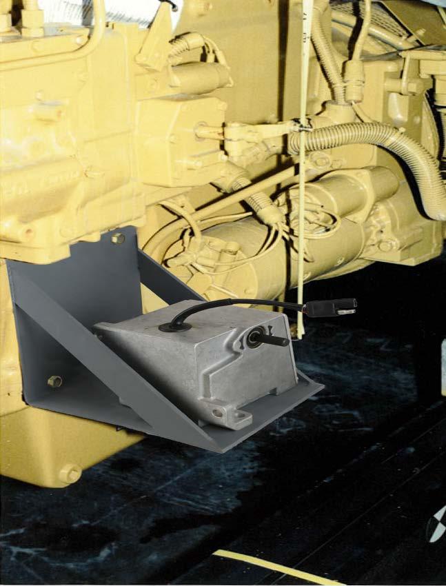
1 KT230 Series Caterpillar 3406 Governor System Installation Kit 30 Years Strong! Introduction The KT230 Series Governor System Installation Kit provides the necessary brackets and hardware to install a GAC precise Electronic Governor on a 3406 Caterpillar Engine. The 225 series actuator is correctly sized for the application and comes in both 12 or 24-volt variation. Caterpillar 3406 series engines have a bell housing with a 5/8-18 UNF thread tapped hole to accept a MSP6720 magnetic speed sensor. If a threaded hole is not available, then the bell housing will need to be drilled. The speed control unit and 225 series actuator can be selected by the customer to meet any specific needs Pre-Installation Disconnect the engine battery cables (negative connection first) to prevent accidental engine starting. The engine should be cool to avoid burns while installing the governor system. The fuel injection pumps stop collar is not intended for continuous duty. You can use the hardened Caterpillar collar part # 2N453. If being used for stand-by then there should be no need to replace it. Figure 1
2 Actuator Installation The Actuator bracket mounts in the vacant are on the left side of the engine, just below the pump and in front of the starter. The actuator must be positioned with its connector pointing up and the label facing the starter. See Fig Install the 225 series electric actuator onto the actuator bracket, using two ¼-20 x 1 bolts, flat washers, lock washers and nuts. 2. Tighten all bolts securely. Actuator Linkage Assembly 1. Thread a ¼-28 jam nut onto each end of the linkage rod. Thread a Ball Bearing Rod end approximately ½ onto each end of the rod. Adjust the Rod ends so that their hole centers are parallel to each other and the distance between them is approximately Attach one end of the linkage rod assembly to the fuel pump shut off lever with a ¼-20 x 1 bolt and locking nut. See Diagram Hold the fuel pump shut off lever in the no fuel position. Slide the actuator lever, flat side away from the actuator, onto the actuator shaft so that the last hole from the shaft is aligned with the ball bearing rod end hole. Push the lever onto the shaft until the linkage is aligned. If necessary, slightly adjust the length of the linkage. Adjust the lever on the shaft until the linkage is vertical. Attach the linkage to the inboard side of the actuator lever with a ¼-20 x 1 bolt and lock nut. 4. Move the linkage assembly thru its full travel. There should be no friction or binding in any position. Pull the actuator lever and linkage to its full fuel position (up) and release. The assembly should snap back to the no fuel position without binding. Recheck all fasteners. Speed Control Unit Installation Mount the Speed Control Unit in the engine control cabinet or engine mounted enclosure. If water, mist or condensation can come into contact with the controller, it should be mounted vertically. Site selection should allow access to the speed control unit adjustments. The speed control unit case mounting holes can be used as a template for drilling holes. Extreme heat should be avoided! Magnetic Speed Sensor Installation 1. Remove the plastic plug from the tapped hole in the engine bell housing. 2. If there is no hole, drill and tap the engine bell housing. The hole must be located perpendicular to the crankshaft centerline and centered over the flywheel. 3. Rotate the engine ring gear until a tooth crown is in the center of the tapped hole. 4. Thread the Magnetic Speed Sensor into the tapped hole until it bottoms on the ring gear tooth. Back the sensor out ½ turn and secure the lock nut
3 Governor System Wiring See specific Speed Control Unit publication for connection information. 1. Connect the electric actuator harness to the actuator. Cut the harness to length. Attach the solderless spade connectors and attach to the ACTUATOR terminals of the Speed Control Unit. 2. Take and cut the Magnetic Speed Sensor harness to length and connect it to the Speed Control Unit with 2 solderless connectors at the Pick-up terminals. 3. Install wire leads from the battery (-) and (+) to the BATTERY input terminals of the Speed Control Unit using solderless spade connectors. Battery polarity must be observed. Fuse protection on the battery (+) of 15 amps is recommended. Optional Speed Trim Control Panel mount and wire the speed trim potentiometer available from GAC. Connect the terminals of the potentiometer to the Speed Control Unit. Speed Control Unit Adjustment 1. Remove the protective covers over the adjustments on the Speed Control Unit. 2. Check to ensure that the GAIN and STABILITY adjustments are in their mid-positions. 3. If used, set the optional external speed trim control to its mid position WARNING-An overspeed shutdown device, Independent of the governor system should be used. Equipment damage or personal injury may result due to loss of engine control 4. Start the engine and rotate the engine SPEED adjustment to the desired engine speed (this is a 25 turn potentiometer). Clockwise adjustment increases engine speed. Governor Performance Adjustments 1.Rotate the Gain adjustment clockwise until instability develops. Gradually move the adjustment counter clockwise until stability returns. Move the adjustment 1/8 of a turn further counter clockwise to insure stable performance. 2. Rotate the STABILITY adjustment clockwise until instability develops. Gradually move the adjustment counter clockwise until stability returns. Move the adjustment 1/8 of a turn further counter clockwise to insure stable performance. 3. Gain and stability adjustments may require minor changes after engine load is applied. Normally adjustments made under no load conditions achieve satisfactory performance. If instability cannot be eliminated, or further performance improvements are required, refer to the Trouble Shooting Sections of the Speed Control Unit or Actuator publications. 4. Apply full load to the generator set. If it will not carry full load, stop the engine and shorten the linkage rod by turning the ball bearing rod ends in. Repeat the load test. It may be necessary to back out the maximum fuel stop screw on the operating and/or the shut off levers until full load is reached.
4 Parts for Complete Set-up ITEM DESCRIPTION QUANITY KT230 Installation Kit Series Electronic Actuator 1 ESD5111 Controller 1 MSP6720 Mag-Pick-up 1 Options TP501 5K-1 Turn Potentiometer 1 EEG6500 Digital Controller Replacement for the ESD KT230 Components Part Number Description Quantity BK230 Actuator Bracket 1 HW /8-16 x HW /8 Lock-Washer 3 HW /8 Flat Washer 3 HW ¼-20 Hex Nut 2 HW ¼-20 Lock Nut 2 RD102 ¼-28 x 12 plated linkage rod 1 HW /16-18 x 1.25 Bolt 2 HW /16 Flat Washer 2 HW /16 Lock Washer 2 HW /16-18 Nut 2 BB110 ¼-28 Bearing End 2 HW /4-20 x 1 Bolt 2 HW ¼ Lock Washer 2 HW ¼ Flat Washer 2 HW ¼ -28 Nut 2 EC Solderless Spade Connector 2 EC Solderless Splice Connector 1

5 KT230 Parts Illustration 30 Years Strong!
KT145 Series John Deere 6076 with Nippondenso Inj. Pump
 KT145 Series John Deere 6076 with Nippondenso Inj. Pump 30 Years Strong! Introduction The KT145 Series Governor System Installation Kit provides the necessary brackets and hardware to install a GAC precise
KT101 Series Governor System Installation Kit Cummins 4B(T) / 6B(T) With CAV/DPA Pump
 / 6B(T) With CAV/DPA Pump") KT101 Series Governor System Installation Kit Cummins 4B(T) / 6B(T) With CAV/DPA Pump 30 Years Strong! Introduction The KT101 Series Governor System Installation Kit provides the necessary brackets and
KT101 Series Governor System Installation Kit Cummins 4B(T) / 6B(T) With CAV/DPA Pump 30 Years Strong! Introduction The KT101 Series Governor System Installation Kit provides the necessary brackets and
ENGINE GOVERNING SYSTEMS
 ENGINE GOVERNING SYSTEMS ESD5400 Series Speed Control Unit INSTALLATION The speed control unit is rugged enough to be placed in a control cabinet or engine mounted enclosure with other dedicated control
ESD5500E Series Speed Control Unit
 ESD5500E Series Speed Control Unit 1 SPECIFICATIONS INTRODUCTION PERFORMANCE Isochronous Operation ± 0.25% or better Speed Range / Governor 1-7.5 KHz Continuous Speed Drift with Temperature ±1% Maximum
10V. the rack of the oil pump must be on the
 P.E.D 20.. ESG2002 series ELECTRONIC GOVERNOR INSTRUCTION A1000C-W ELECTROMAGNETIC ACTUATOR Before inst al l el ectromag neti c, p lea se inspect that the rack of the oil pump shouldn' t be stuck in any
ESD5550 / 5570 Series Speed Control Units
 ESD5550 / 5570 Series Speed Control Units 1 The speed control unit is rugged enough to be placed in a control cabinet or engine mounted enclosure with other dedicated control equipment. If water, mist,
Installation Manual Installation Kit. for EPG 1712/1724 Electric Actuator on the Caterpillar D3406 Engine. Manual 54086
 Installation Manual 8924-600 Installation Kit for EPG 1712/1724 Electric Actuator on the Caterpillar D3406 Engine Manual 54086 DEFINITIONS This is the safety alert symbol. It is used to alert you to potential
ESD5100 Series Speed Control Unit PART NUMBER ESD5120 ESD (127)
") ESD5100 Series Speed Control Unit 1 INTRODUCTI The ESD5100 Series speed control unit is an all electronic device designed to control engine speed with fast and precise response to transient load changes.
ESD5100 Series Speed Control Unit 1 INTRODUCTI The ESD5100 Series speed control unit is an all electronic device designed to control engine speed with fast and precise response to transient load changes.
PED 5000 ELECTRIC ACTUATOR
 ENGINE GOVERNING SYSTEMS PRODUCT INFORMATION BULLETIN JAN 2002 PED 5000 ELECTRIC ACTUATOR INTRODUCTION The PED 5000 electric actuator is a rotatory output, linear torque, proportional servo. This electromechanical
EDG6000 Electronic Digital Governor
 INTRODUCTION GAC s digital governor is designed to regulate engine speed on diesel and gaseous fueled engines. When paired with a GAC actuator the EDG is a suitable upgrade for any mechanical governor
ESD-5500E Series - Speed Control Unit
 ESD-5500E Series - Speed Control Unit INTRODUCTION The ESD-5500E Series speed control unit is an all electronic device designed to control engine speed with last and precise response to transient load
EDG5500 Electronic Digital Governor With Quikset Display
 1 INTRODUCTION EDG5500 Electronic Digital Governor With Quikset Display GAC s EDG5500 digital governor is designed to regulate engine speed on diesel and gaseous-fueled engines. The EDG system is a suitable
ALR-190-Series Integral Actuator
 ALR-190-Series Integral Actuator Introduction The ALR-190 Series Integral Actuator is designed to mount integral to various injection Pumps of small engines. No external linkage or brackets are required
DESCRIPTION & OPERATION
 HEADLIGHT DOORS 1998 ACCESSORIES & EQUIPMENT General Motors Corp. - Headlight Doors DESCRIPTION & OPERATION NOTE: Headlight Doors Module (HDM) may also be referred to as headlight opening door actuator
EG3002. Electronic Engine Governor Controller User Manual
 EG3002 Electronic Engine Governor Controller User Manual Engine Start Smoke Limiting function & IDLE Speed Setting For External, Built-in, PT-Pump type and hydraulic drive actuators Newly added extreme
EEG6500 Enhanced Electronic Governor
 1 2 INTRODUCTION GAC s EEG6500 digital governor is designed to regulate engine speed on diesel and gaseous-fueled engines. The EEG system is a suitable replacement for any mechanical governor system that
IGA225 Integrated Governor & Actuator
 INTRODUCTION GAC s integrated digital governor and actuator is designed to regulate engine speed on diesel and gaseous fueled engines. The IGA is a suitable upgrade for any mechanical governor system that
Installation Manual Installation Kit. for EPG 1712/1724 Electric Actuator on the Caterpillar 3208 Engine. Manual (Revision A)
") Installation Manual 8924-608 Installation Kit for EPG 1712/1724 Electric Actuator on the Caterpillar 3208 Engine Manual 54092 (Revision A) DEFINITIONS This is the safety alert symbol. It is used to alert
Installation Manual 8924-608 Installation Kit for EPG 1712/1724 Electric Actuator on the Caterpillar 3208 Engine Manual 54092 (Revision A) DEFINITIONS This is the safety alert symbol. It is used to alert
IMO-517 (7027) ISSUE 3/97 ERA12, 25, 50, 83, 125, 167, 208 AND 250 ELECTRIC ACTUATORS INSTALLATION, MAINTENANCE AND OPERATING INSTRUCTIONS
 ISSUE 3/97 ERA12, 25, 50, 83, 125, 167, 208 AND 250 ELECTRIC ACTUATORS INSTALLATION, MAINTENANCE AND OPERATING INSTRUCTIONS") ERA12, 25, 50, 83, 125, 167, IMO-517 (7027) ISSUE 3/97 208 AND 250 ELECTRIC ACTUATORS INSTALLATION, MAINTENANCE AND OPERATING INSTRUCTIONS 2 Table of Contents 1 GENERAL...........................................
ERA12, 25, 50, 83, 125, 167, IMO-517 (7027) ISSUE 3/97 208 AND 250 ELECTRIC ACTUATORS INSTALLATION, MAINTENANCE AND OPERATING INSTRUCTIONS 2 Table of Contents 1 GENERAL...........................................
ESD-5550/5570 Speed Control Unit. Manual
 Manual Doc.-No. : ESD-5550- Version : 1.0 Date of Issue : HUEGLI TECH Switzerland This document, and the information contained herein is the intellectual property of HUEGLI TECH. It is to be used only
EG1069X. Generator Electronic Governor Controller Operation Manual
 EG1069X Generator Electronic Governor Controller Operation Manual Smoke Limit Controller Compatible with Barber Colman Dyn1-1069X series *Use for reference purpose only and not a genuine Barber Colman
EPG 1712/1724 or 512/524 Electric Actuator Installation. Product Manual (Revision NEW) Original Instructions
 Original Instructions") Product Manual 54120 (Revision NEW) Original Instructions EPG 1712/1724 or 512/524 Electric Actuator Installation On the Robert Bosch Fuel Pump Replacing RQ, RS, or RSV Mechanical Governor 8924-867 Kit
Product Manual 54120 (Revision NEW) Original Instructions EPG 1712/1724 or 512/524 Electric Actuator Installation On the Robert Bosch Fuel Pump Replacing RQ, RS, or RSV Mechanical Governor 8924-867 Kit
ESD-5550/5570 Series - Speed Control Unit
 ESD-5550/5570 Series - Speed Control Unit Table 1. Starting Fuel Control ESD-5550/5570 Series Speed Control Units Speed Ramping Single Element Speed Switch (Overspeed) 2 Element Speed Switch (Overspeed
with discrete output (Overspeed) with auxiliary input (Synchronizer and Load Sharing)
 with auxiliary input (Synchronizer and Load Sharing)") Document: Digital Speed Governor Versions SDG-25 SDG-35 with discrete output (Overspeed) with auxiliary input (Synchronizer and Load Sharing) Integrated Heatsink Programming and Diagnostic Port Mode and
Document: Digital Speed Governor Versions SDG-25 SDG-35 with discrete output (Overspeed) with auxiliary input (Synchronizer and Load Sharing) Integrated Heatsink Programming and Diagnostic Port Mode and
2000 Dodge Durango ACCESSORIES & EQUIPMENT' 'Power Windows - Dakota & Durango 2000 ACCESSORIES & EQUIPMENT. Power Windows - Dakota & Durango
 DESCRIPTION & OPERATION 2000 ACCESSORIES & EQUIPMENT Power Windows - Dakota & Durango A permanent magnet motor moves each of the power windows. A master switch on driver's door controls all windows and
225 SERIES ELECTRIC ACTUATOR
 Generator Control Specialists 48A Ainsdale Street Telephone: 0500 800 225 P.O. Box 30 West Chermside, Qld 4032 Facsimile: 3350 1654 Grange, Qld 4051 Australia Mobile: 0427 22 00 18 Australia email: info@powersystems.com.au
ECU. Speed Switch Manual. Contents. ECU is a registered trademark of Engineering Concepts Unlimited Inc.
 ECU Speed Switch Manual Contents ECU is a registered trademark of Engineering Concepts Unlimited Inc. Contents Unit review Magnetic pickup example AC input example Design Guide Troubleshooting guide 24
ALR Series Electronic Linear Actuators
 1 The ALR Series Actuator is designed to replace the OEM equipped shut down solenoid. To properly install the ALR actuator, a precise measurement must be obtained from the removed OEM equipped shutdown
UNIVERSAL ELECTRA-STEER FOR 2 COLUMN 220w Plain w Polished w Plain w Polished
 UNIVERSAL ELECTRA-STEER FOR 2 COLUMN 220w Plain 8052810 220w Polished 8052610 360w Plain 8052780 360w Polished 8052760 Full refund will NOT be granted to any kits that are damaged, scratched, or altered
LAKEWOOD/QUICKTIME SAFETY BELLHOUSING INSTALLATION INSTRUCTIONS
 LAKEWOOD/QUICKTIME SAFETY BELLHOUSING INSTALLATION INSTRUCTIONS Congratulations on your purchase of the finest quality steel bellhousing available today. 100% Manufactured in the USA! Please understand
GPS AutoSteer System Installation Manual
 GPS AutoSteer System Installation Manual Supported Vehicles Case IH Vehicles Case 2577 Combines Case 2588 Combines Accuguide Ready PN: 602-0233-01-A LEGAL DISCLAIMER Note: Read and follow ALL instructions
Powers TM Controls EA 338 Electronic Actuator
 Powers TM Controls Technical Instructions Document No. 155-136P25 EA 338-1 Description Features 24 Vac power supply. The s are used with floor mount linkage kits to operate dampers in HVAC installations.
EG1065X. Compatible with Barber Colman* Dyn1-1065X series * Use for reference purpose only and not a genuine Barber Colman product.
 EG1065X Generator Electronic Governor Controller Operation Manual Compatible with Barber Colman* Dyn1-1065X series * Use for reference purpose only and not a genuine Barber Colman product. Headquarters
PRODUCT SERIES: DPG-2100
 Service Information PRODUCT SERIES: DPG-2100 DYNA Programmable Governor for Isochronous Generators Calibration and Troubleshooting for DPG-2101, DPG-2102, DPG-2103, DPG-2104 DPG-2100 The DPG-2100 governors
ATB Series - Integral Throttle Body Actuators
 ATB Series - Integral Throttle Body Actuators INTRODUCTION Low-Cost, Maintenance Free, Compact Design Various Bore Sizes Available (25-85mm) Precise, Real-Time Engine Speed Control Flexible Design for
PRODUCT SAFETY NOTICE
 PRODUCT SAFETY NOTICE Congratulations. This vehicle has been equipped with a Firestone air suspension system. This suspension will enhance the vehicle s handling when loaded, however, the vehicle s performance
ENGINE GOVERNING SYSTEMS LSM672 LOAD SHARING MODULE. GOVERNORS AMERICA CORP. 720 Silver Street Agawam, MA , USA MEMBER
 ENGINE GOVERNING SYSTEMS LSM672 LOAD SHARING MODULE MEMBER GOVERNORS AMERICA CORP. 720 Silver Street Agawam, MA 01001-2907, USA LSM672 LOAD SHARING MODULE PRODUCT TECHNICAL INFORMATION PTI 4000 AUGUST
WIPER/WASHER SYSTEM - FRONT ACCESSORIES & EQUIPMENT General Motors Corp. - Front Wiper/Washer System
 WIPER/WASHER SYSTEM - FRONT 1998 ACCESSORIES & EQUIPMENT General Motors Corp. - Front Wiper/Washer System DESCRIPTION & OPERATION CAUTION: To prevent scratching, wet the windshield before turning on wipers.
OFFICE PARTITIONS. Data Port Openings. Use cable tie bracket to dress data cables under panels. STEP 1
 N Power Box Opening Data Port Openings Rear View Front View Remove opening blanks on raceway cover for power and data. If panel contains no electric or data and is used as a pass-thru, leave opening blanks
M Damper Mount Linkage Kit Installation. Item Description Quantity Item Description Quantity Nuts 2
 FANs 268.1, 1628.3 Installation Bulletin M9000-150 Issue Date 0796 M9000-150 Damper Mount Linkage Kit Installation 21 18 19 20 2 22 17 2 4 3 2 15.5 393.7 1 17 16 15 11 13 12 8 9 10 2 5 Note: Damper mount
1110 & 1210 Compact Diesel
 Ford Service Manual 1110 & 1210 Compact Diesel Service Manual THIS IS A MANUAL PRODUCED BY JENSALES INC. WITHOUT THE AUTHORIZATION OF FORD OR IT S SUCCESSORS. FORD AND IT S SUCCESSORS ARE NOT RESPONSIBLE
ESC2301. Universal Electronic Governor Controller Operation Manual
 ESC2301 Universal Electronic Governor Controller Operation Manual *Replaces most Woodward, Barber Colman & Cummins Speed Controls Features Smoke Limit Control, Idle Speed Control, 12V or 24V input Suitable
FM200 FLOW/NO-FLOW MONITOR INSTALLATION AND TECHNICAL MANUAL 120 VAC MODEL 6/1/2017
 FM200 FLOW/NO-FLOW MONITOR INSTALLATION AND TECHNICAL MANUAL 120 VAC MODEL 6/1/2017 Maxi-Tronic, Inc. 417 Wards Corner Road Loveland, OH 45140 513.398.2500 800.659.8250 FAX: 513.398.2536 info@maxitronic.com
DYNA Power Control Manual For Plus 1, Plus 2, Plus 4 and Plus 6 Ft. Lb. Systems
 DYNA Power Control Manual For Plus 1, Plus 2, Plus 4 and Plus 6 Ft. Lb. Systems General Information... 2 Installation... 3 Calibration and Adjustments... 5 Maintenance Troubleshooting... 6 Plus 1 & Plus
ALTERNATOR PRECAUTIONS. Some precautions should be taken when working on this, or any other, AC charging system.
 The alternator charging system is a negative (-) ground system which consists of an alternator, a regulator, a charge indicator, a storage battery and wiring connecting the components, and fuse link wire.
GPS AutoSteer System Installation Manual
 GPS AutoSteer System Installation Manual Supported Vehicles New Holland Combines CR 9040 CX 9040 CR 9050 CX 9050 CR 9060 CX 9060 CR 9070 CX 9070 CR 9080 CX 9080 IntelliSteer Ready PN: 602-0231-01-A LEGAL
Florham Park, NJ USA Call (ASCO) for sales or service
 for sales or service") Operator s Manual 7000 Series ATS Automatic Transfer Switches D design, 30 through 230 A DANGER is used in this manual to warn of a hazard situation which, if not avoided, will result in death or serious
Operator s Manual 7000 Series ATS Automatic Transfer Switches D design, 30 through 230 A DANGER is used in this manual to warn of a hazard situation which, if not avoided, will result in death or serious
Bulletin 1494C Cable Operated Disconnect Switch Kit (600A) Installation Instructions (Cat 1494C- _ Series 2 : 600A)
 Installation Instructions (Cat 1494C- _ Series 2 : 600A)") Bulletin 494C Cable Operated Disconnect Switch Kit (600A) Installation Instructions (Cat 494C- _ Series : 600A) ATTENTION: To prevent electrical shock, disconnect from power source before installing or
Bulletin 494C Cable Operated Disconnect Switch Kit (600A) Installation Instructions (Cat 494C- _ Series : 600A) ATTENTION: To prevent electrical shock, disconnect from power source before installing or
GPS AutoSteer System Installation Manual
 GPS AutoSteer System Installation Manual Supported Vehicles Case IH Vehicles Case 5088 Combines Case 6088 Combines Case 7088 Combines Accuguide Ready PN: 602-0250-01-A LEGAL DISCLAIMER Note: Read and follow
EEG6550 Enhanced Electronic Governor
 1 2 INTRODUCTION Computer SPECIFICATIONS PERFORMANCE Isochronous Operation ± 0.25% Speed Range / Governor Idle Adjust Droop Range Speed Trim Supply Polarity Power Consumption Speed Sensor Signal Actuator
TOYOTA RAV TRAILER WIRE HARNESS Section I Installation Preparation
 Section I Installation Preparation Part Number: 08921-42900 Kit Contents Item # Quantity Reqd. Description 1 1 Converter 2 1 Wire harness 3 1 Sub wire harness No.1 4 2 Plastic Tie (300mm) 5 21 Plastic
mi Model 108 Compact Tractor Parts Catalog
 mi Model 108 Compact Tractor Parts Catalog Catalog No. 1226 PRICE 75 CENTS CASE MODEL 108 COMPACT TRACTOR Parts Catalog No. 1226 Leitch 2500 9-72 "'^^^l" 1" ifif --C: ^1=5 t^dj d- CASE MODEL 108 COMPACT
PH3 AIR INTAKE EMERGENCY SHUT-OFF VALVE WITH POWERGUARD SMART OVERSPEED LIMITER. Generic PH3 Truck Shut-Off Valve Kit.
 PH3 AIR INTAKE EMERGENCY SHUT-OFF VALVE WITH POWERGUARD SMART OVERSPEED LIMITER Generic PH3 Truck Shut-Off Valve Kit www.powerhalt.com INSTALLATION REQUIREMENTS & RECOMMENDATIONS: Prior to the installation,
S6100 SERIES REVERSIBLE PANIC/FIRE EXIT RIM DEVICES INSTALLATION INSTRUCTIONS
 801 Avenida Acaso, Camarillo, Ca. 93012 (805) 494-0622 www.sdcsecurity.com E-mail: service@sdcsecurity.com S6100 SERIES REVERSIBLE PANIC/FIRE EXIT RIM DEVICES INSTALLATION INSTRUCTIONS These instructions
Service Manual. LL30002 Rev. 7/03. HEAVY DUTY PUSH/PULL TYPE CLUTCHES
 Service Manual LL30002 Rev. 7/03 HEAVY DUTY PUSH/PULL TYPE CLUTCHES www.haldex.com Table of Contents Section One - Push Type Clutches Clutch Assembly Cutaway Detail............................1 Clutch
INSTALLATION INSTRUCTIONS
 INSTALLATION INSTRUCTIONS WARNING: WARNING: www.altronicinc.com DEVIATION DEVIATION FROM THESE FROM INSTRUCTIONS THESE INSTRUCTIONS MAY LEAD MAY TO LEAD IMPROPER TO IMPROPER OP- ERATION OF ENGINE THE MACHINE
Bulletin 1494V Variable Depth, Flange Operated Disconnect Switch Kits for 400 and 600 Amperes (Series A) Switches
 Switches") Bulletin 494V Variable Depth, Flange Operated Disconnect Switch Kits for and Amperes (Series A) Switches ATTENTION: To prevent electrical shock, disconnect from power source before installing or servicing.
Bulletin 494V Variable Depth, Flange Operated Disconnect Switch Kits for and Amperes (Series A) Switches ATTENTION: To prevent electrical shock, disconnect from power source before installing or servicing.
1984 Toyota Pickup. IGNITION SYSTEM - NIPPONDENSO ELECTRONIC' '1984 ELECTRICAL Toyota Ignition System - Nippondenso Electronic Ignition
 ADJUSTMENTS 1984 Toyota Pickup PICK-UP COIL-TO-SIGNAL ROTOR (RELUCTOR) AIR GAP 1. Using a flat, non-magnetic feeler gauge, check air gap between pick-up coil pole piece and each reluctor tooth. Gaps should
Service Instruction. Introduction of fuel injection pumps with tight governor control. Fig 1
 Service Instruction Note DIESEL SEP 2002 Based on UK DT319 (EN) SIN 508 DPG PUMPS (DPA) EQUIPMENT: SUBJECT: Pumps 3230F560T, 3349F250T, 3340F260T, 3260F530T and 3340F280T fitted to gen set and constant
EG3000. Generator Electronic Governor Controller Operation Manual
 EG3000 Generator Electronic Governor Controller Operation Manual Smoke Limit Control, Idle Speed Control, suitable for Builtin, Non-Built-in and PT Pump Type Actuator. SP POWERWORLD LTD Willows, Waterside,
SHAVED-DX. Installation Manual & Operation Instructions. Trouble Shooting Reverse Polarity Wiring Problems
 Trouble Shooting Reverse Polarity Wiring Problems Switch doesn't work properly but the shaved kit transmitters do work Step 1 Did you purchase a switch kit designed for three switches and only use two
DESCRIPTION & OPERATION
 SEATS - POWER 1998 ACCESSORIES & EQUIPMENT General Motors Corp. - Power Seats DESCRIPTION & OPERATION Power seats operate using toggle switches located on seat side. Seat adjusters are powered by a 12-volt,
ANDCO Eagle Actuator Instruction Manual
 ANDCO Actuators ANDCO Eagle Actuator Instruction Manual The information contained in this manual is essential to safe, successful, long term operation of your Andco Eagle Linear Actuator. Read and follow
UNISTEER Performance Products UNIVERSAL HOT ROD ELECTRA-STEER KIT
 UNISTEER Performance Products UNIVERSAL HOT ROD ELECTRA-STEER KIT 8051500 BEFORE YOU START PLEASE READ! Designing steering systems requires an understanding of steering function and design. If you are
Ford C4 and C6 Floor Mount Automatic Transmission Shifter Installation Instructions
 Ford C4 and C6 Mount Automatic Transmission Shifter Installation Instructions Building American Quality With A Lifetime Warranty! TOLL FREE 1-877-469-7440 tech@lokar.com www.lokar.com Ford C4 and C6 Mount
INSTALLATION INSTRUCTIONS FOR ELECTRIC CHOKE KIT P/Ns , S, &
 INSTALLATION INSTRUCTIONS FOR ELECTRIC CHOKE KIT P/Ns 45-224, 45-224S, & 745-224 INTRODUCTION: Congratulations on your purchase of a new electric choke kit from Holley! These kits can be used to convert
LIPPERTCOMPONENTS, INC.
 LIPPERTCOMPONENTS, INC. SCHWINTEK INWALL SLIDEOUT SYSTEM OPERATION AND SERVICE MANUAL Contents I. Controls 1-1 System components 1 1-1A versions C1 & C2 2 1-2 Motor wiring harness connections 3 1-3 Extend
WPS-104 Heater Installation Instructions For 500EFI, 700 XP, & Crew Applications
 WPS-104 Heater Installation Instructions For 500EFI, 700 XP, & Crew Applications ORDER OF INSTALLATION FOR A COMPLETE ENCLOSURE OF A RANGERWARE WPS (Weather Protection System) IS AS FOLLOWS: 1. Heater
GM Floor Mount Automatic Transmission Shifter Installation Instructions
 GM Mount Automatic Transmission Shifter Installation Instructions Building American Quality With A Lifetime Warranty! TOLL FREE 1-877-469-7440 tech@lokar.com www.lokar.com GM Mount Automatic Transmission
Constant Speed Control
 Eaton Heavy Duty Hydrostatics No. 4-51 June, 1995 Installation & Operating Instructions Constant Speed Control Operating Instructions for Constant Speed Control (The valve package, speed sensor and electronic
Installation Kit. Product Manual (Revision NEW) Original Instructions
 Original Instructions") Product Manual 54050 (Revision NEW) Original Instructions 8924-606 Installation Kit for EPG 1712/1724 Electric Actuator on the Cummins VT/VTA-1710 GS Engines Installation Manual DEFINITIONS This is the
Product Manual 54050 (Revision NEW) Original Instructions 8924-606 Installation Kit for EPG 1712/1724 Electric Actuator on the Cummins VT/VTA-1710 GS Engines Installation Manual DEFINITIONS This is the
Security Door Controls
 Security Door Controls 801 Avenida Acaso, Camarillo, ca. 930 (805) 494-0622 Fax: (805) 494-8861 www.sdcsecurity.com E-mail: service@sdcsecurity.com 1575-1576 EMLOCK R INSTALLATION INSTRUCTIONS During installation,
COMPONENT WORK SAMPLE 8 Simulated Assembly MAINTENANCE MANUAL. From 1974 to March 15, 2003
 COMPONENT WORK SAMPLE 8 Simulated Assembly MAINTENANCE MANUAL From 1974 to March 15, 2003 Copyright 2008 VALPAR International Corporation P.O. Box 5767 Tucson, Arizona 85703-5767 All rights reserved. No
Product Description. Product Numbers. Warning/Caution Notations. Required Tools. Wiring. Prerequisites
 Document No. 155-302N VE 598 Electronic Flowrite Valve Field Assembly Product Description The VE 598 Electronic Valve Assemblies consist of an electronic actuator, linkage kit, and a valve body assembly.
Illustrated Parts List to
 TYPE NUMBERS 0101, 0102, 0106, 0108, 0109, 0115 through 0224, 0415, 0418, 0467, 0468, 0601 through 0683, 3101 through 3108, 3110 through 3163, 3167 through 3181. Illustrated Parts List Model Series 124700
Series BFM Bulk Flow Monitor 1A FUSE RED LED RELAY. Part Number BFM-1 BFM-2 BFM-3 BFS-1
 Series Bulk Flow Monitor Specifications - Installation and Operating Instructions Bulletin FL-1-4x 3/4 CONDUIT KNOCKOUTS BFS 1A FUSE RED LED RELAY 5-9/64 [130.45] TRANSFORMER 3[76.20] GREEN LED 7 [177.80]
Detroit Speed, Inc. Electric Headlight Door Kit Corvette P/N: &
 Detroit Speed, Inc. Electric Headlight Door Kit 1968-82 Corvette P/N: 122006 & 122007 The Detroit Speed Inc. Electric Headlight Door Kit replaces the stock vacuum actuated system on all 1968-82 Corvettes.
PN R CHEVY CAMARO w/reverse Two panel Sequential LED Taillight kit installation guide. Kit Contents:
 Two panel Sequential LED Taillight kit installation guide Kit Contents: 2 LED panels 4 rubber grommets 1 power wire with t-tap 1 driver side LED harness, 24 1 passenger side LED harness, 48 2 LED extension
2001 Chevrolet Corvette ACCESSORIES & EQUIPMENT Headlight Doors - Corvette
 DESCRIPTION & OPERATION 2001 ACCESSORIES & EQUIPMENT Headlight Doors - Corvette Headlight doors are actuated by reversible electric motors mounted near each headlight door. Battery voltage is applied at
Chrysler 727, 904, 518 Floor Mount Automatic Transmission Shifter Installation Instructions
 Chrysler 727, 904, 518 Mount Automatic Transmission Shifter Installation Instructions Building American Quality With A Lifetime Warranty! TOLL FREE 1-877-469-7440 tech@lokar.com www.lokar.com Release Button
Wheel Angle Sensor Kit Installation
 Wheel Angle Sensor Kit Installation Item Component Part Number Qty 1. Bracket Kit, WAS 200-0572-01 1 2. WAS Assembly 200-0468-01 1 3. Instruction Guide 602-0456-01 1 602-0456-01-A Overview Always shut
HOW - TO WIRING & LIGHTING
 HOW - TO WIRING & LIGHTING Tool And Material Checklist Test Light Service Manual Penetrating Oil Long-Nose Pliers T-Square or Right Angle Screwdriver Black Electrical Tape Fuses Fuse Puller Cloth or Paper
CONTENTS. Product Features and Specifications...1. Installation Requirement Steps of Installation.. 5. Exploded View Test Run...
 CONTENTS Product Features and Specifications...1 Installation Requirement... 3 Steps of Installation.. 5 Exploded View...18 Test Run...21 Operation Instruction...22 Maintenance... 23 Trouble Shooting...
UNIVERSAL ATOMIC DIESEL MODEL (16 H.P.) PARTS MANUAL. Universal Motors
 PARTS MANUAL. Universal Motors") UNIVERSAL ATOMIC DIESEL MODEL 20 5416 (16 H.P.) PARTS MANUAL Universal Motors This copy of the Universal Motors Owners Manual has been re-created using images computer scanned from a manual rather than
UNIVERSAL ATOMIC DIESEL MODEL 20 5416 (16 H.P.) PARTS MANUAL Universal Motors This copy of the Universal Motors Owners Manual has been re-created using images computer scanned from a manual rather than
C-Drive 7 Motor Control Unit For Electric Steering & Autopilots
 C-Drive 7 Motor Control Unit For Electric Steering & Autopilots OPERATION AND INSTALLATION MANUAL www.tmq.com.au TMQ C-Drive7 Page 2 of 20 28/04/2009 Index INTRODUCTION 4 BLOCK DIAGRAM OF FULL SYSTEM 5
Florham Park, NJ USA Call (ASCO) for sales or service
 for sales or service") Operator s Manual 4000 Series ATS Automatic Open-Transition Transfer Switches D design 30 230A, J design 260 600A, H-design 800 1200A, G-design 1600 4000A, F-design 4000A DANGER is used in this manual
Operator s Manual 4000 Series ATS Automatic Open-Transition Transfer Switches D design 30 230A, J design 260 600A, H-design 800 1200A, G-design 1600 4000A, F-design 4000A DANGER is used in this manual
Electric Lock Part List
 When the length of your gate is more than 1.5 meters, we recommend installing an Electric Lock. An electric lock provides extra security and stability to your gate system. The lock provides extra protection
Contents. Section 5: Adjustments Ball Detect Adjustment Transport Band Tension Adjustment
 Contents Section 5: Adjustments... 5-3 1. Ball Detect Adjustment... 5-3 2. Transport Band Tension Adjustment... 5-5 3. Transport Band Drive Belt Tension Adjustment... 5-7 4. Ball Cushion Adjustment...
Product Manual (Revision A) Original Instructions. EG-3P Actuator Installation on Detroit Diesel V-149 Engine. Kit Installation Manual
 Original Instructions. EG-3P Actuator Installation on Detroit Diesel V-149 Engine. Kit Installation Manual") Product Manual 54005 (Revision A) Original Instructions EG-3P Actuator Installation on Detroit Diesel V-149 Engine Kit Installation Manual General Precautions Read this entire manual and all other publications
Product Manual 54005 (Revision A) Original Instructions EG-3P Actuator Installation on Detroit Diesel V-149 Engine Kit Installation Manual General Precautions Read this entire manual and all other publications
Mixer Discharge Door Adjustment on models; 30, 42, 54, 81, 108, 135 mixers.
 Knowledge Base Article Type: Instructions Mixer Discharge Door Adjustment on models; 30, 42, 54, 81, 108, 135 mixers. Description: Instructions on How to set-up and adjust the discharge door on Columbia
UG-5.7, UG-8, UG10 Governor
 54042D UG-5.7, UG-8, UG10 Governor Installation Manual Manual 54042D ! WARNING Read this entire manual and all other publications pertaining to the work to be performed before installing, operating, or
R81EAA Type Plug-In Electronic Circuit Board Kit For Series M100 Motor Actuators
 R81EAA Type Plug-In Electronic Circuit Board Kit For Series M100 Motor Actuators Installation Sheets Manual 121 Relays and Contactors Section R Technical Bulletin R81EAA Application R81 plug-in electronic
650 Series Cargo Van Lift Mounting Instructions Ford Transit (Standard Roof) 2015-Present
 2015-Present") TOMMY GATE OWNER'S / OPERATOR'S MANUAL 650 Series 650 LB Capacity 650 Series Cargo Van Lift Mounting Instructions Ford Transit (Standard Roof) 2015-Present Installing the Base Plate 1. Examine the interior
TOMMY GATE OWNER'S / OPERATOR'S MANUAL 650 Series 650 LB Capacity 650 Series Cargo Van Lift Mounting Instructions Ford Transit (Standard Roof) 2015-Present Installing the Base Plate 1. Examine the interior
1999 Toyota RAV ACCESSORIES & EQUIPMENT Cruise Control Systems - RAV4
 1999 ACCESSORIES & EQUIPMENT Cruise Control Systems - RAV4 DESCRIPTION WARNING: Deactivate air bag system before performing any service operation. See AIR BAG RESTRAINT SYSTEMS article. DO NOT apply electrical
Doors. Table of Contents
 Doors Table of Contents Sub-Headings Safety 2 Warnings 2 Cautions 2 s 2 Introduction 2 Description of Operation 2 Door Control Assembly Removal 2 Remove Cotter Pin and Clevis Pin From Rod-End Bracket 3
62 Deck Idler Kit High Speed
 Part No. 00 FORM NO. -899 6 Deck Idler Kit High Speed For Model 70 Serial No. 99000 to 99000 For Model 7 Serial No. 9900 to 99000 INSTALLATION INSTRUCTIONS Loose Parts Note: Use the chart below to identify
Ford AOD-4R70W-AODE Cable Operated Shifter Installation Instructions
 Ford AOD-4R70W-AODE Cable Operated Shifter Installation Instructions Building American Quality With A Lifetime Warranty! TOLL FREE 1-877-469-7440 tech@lokar.com www.lokar.com Ford AOD-4R70W-AODE Cable
DRIVE AXLE Volvo 960 DESCRIPTION & OPERATION AXLE IDENTIFICATION DRIVE AXLES Volvo Differentials & Axle Shafts
 DRIVE AXLE 1994 Volvo 960 1994 DRIVE AXLES Volvo Differentials & Axle Shafts 960 DESCRIPTION & OPERATION All 960 station wagon models use type 1041 rear axle assembly. All 960 4-door models use type 1045
Syntron EB-00 Vibratory Parts Feeder GENERAL MANUAL
 Syntron EB-00 Vibratory Parts Feeder GENERAL MANUAL INSTALLATION OPERATION MAINTENANCE Thank you for buying your equipment from Homer City Automation Inc. This manual will help you to understand how your
PM300E Voltage Regulator Instruction Manual
 PM300E Voltage Regulator Instruction Manual A Regal Brand 1. INTRODUCTION The PM300E voltage regulator is an encapsulated electronic voltage regulator which controls the output of a brushless AC generator