CONTENTS. Product Features and Specifications...1. Installation Requirement Steps of Installation.. 5. Exploded View Test Run...
|
|
|
- Giles Bishop
- 6 years ago
- Views:
Transcription
1
2 CONTENTS Product Features and Specifications...1 Installation Requirement... 3 Steps of Installation.. 5 Exploded View...18 Test Run...21 Operation Instruction...22 Maintenance Trouble Shooting Parts List
 Compact design Dual hydraulic cylinders, designed and made on ANSI standards, utilizing NOK oil seals in the cylinders Self- lubricating UHMW Polyethylene sliders and bronze bushings Single-point")
3 I. PRODUCT FEATURES AND SPECIFICATIONS FLOORPLATE CHAIN-DRIVE TWO POST LIFT Model BP (See Fig. 1) Compact design Dual hydraulic cylinders, designed and made on ANSI standards, utilizing NOK oil seals in the cylinders Self- lubricating UHMW Polyethylene sliders and bronze bushings Single-point safety release and dual safety design Super Symmetric arms design with 3-stages front arms and 2-stages rear arms. Stackable rubber pad with 1.5, 2.5 and 5 extension adaptors Fig. 1 MODEL BP SPECIFICATIONS Model Style Lifting Capacity Lifting Time Lifting Height Overall Height Overall Width Width Between Columns Minimum Pad Height Gross Weight Motor BP Floor plate Chain-drive 4.5T 10,000lbs 62S mm 77 3/8 86 3/8 2841mm 111 7/8 3534mm 139 1/8 2850mm 112 1/4 115mm 4 1/2 745Kg 1640lbs 3.0 HP 1
4 Arm Swing View For Model BP Fig. 2 2

")

 Pliers Ratchet With")
")

5 II. INSTALLATION REQUIREMENT A. TOOLS REQUIRED Rotary Hammer Drill (3/4 ) Carpenter s Chalk Hammer Screw Sets Level Bar Tape Measure Crescent Wrench (12") Pliers Ratchet With Socket (28 mm ) Allen Head Wrench (6 mm ) Wrench set (mm) Vise Grips (10 #, 13 #, 14 #, 15 #, 17 #, 19 #, 24 #, 27 # ) Fig. 3 3
6 B. SPECIFICATIONS OF CONCRETE (See Fig. 4). Specifications of concrete must be adhered to the specification as following. Failure to do so may result in lift and or vehicle falling. 1. Concrete must have 4 inches minimum and must be totally cured before lift installation. 2. Concrete must be in good condition and must have a test strength 3,000psi minimum. 3. Floors must be level with no cracks or holes. 71 Concrete strength 3000psi 4 4 Fig. 4 C. POWER SUPPLY 220 volt single phase motor on a 30 amp breaker with minimum of 10 gauge wire. Operating voltage range is 208v-230v. 4

.")
. 2.")
7 III. Location of installation A. Location of Installation Check and ensure the installation location (concrete, layout, space size etc.) is suitable for lift installation. B. Use a carpenter s chalk line to establish installation layout of base plate (See Fig. 5). Click line 139-1/8 Fig. 5 Model BP C. Check the parts before assembly. 1. Packaged lift, hydraulic power unit and parts box (See Fig. 6). 2. Move the lift with fork lift or hoist, open the outer packing and check the parts with the shipment list (See Fig. 7). Fig.6 Fig.7 Shipment Parts list Floor cover Metal Serial No. Parts box 5


. 81 Fig. 8 5.")
. Fig. 9 6.")
8 3. Loosen the bolts on the upper package stand, remove the upper column then remove the package stand. 4. Set aside the parts and check the parts according to the shipment parts list (See Fig. 8). 81 Fig Open the carton of parts and check the parts according to parts box list (See Fig. 9). Fig Check the parts in the parts bag according to parts bag list (See Fig. 10). Fig. 10 6

. Power side column Offside column Car-in direction Install top connecting plate with M8*20 hex bolt, nut and lock washer Fig.")

9 D. Position power side column Lay down two columns on the installation site parallel. Position the power side column according to the actual installation site and install top plate and top connecting plate assembly. Usually, it is suggested to install power side column on the front-right side from which vehicles are driven into the lift (See Fig. 11). Power side column Offside column Car-in direction Install top connecting plate with M8*20 hex bolt, nut and lock washer Fig. 11 E. Connecting the cables 1.Push the carriages higher than chain pulley (See Fig. 12). B, Push the carriages higher than chain pulley, cable passes through the top of the carriages and passes through the hole on the bottom steel plate of the carriages C, Pull out cable A, Cable pass in the carriage Fig. 12 7


10 2.Push the carriages to the bottom of the columns (See Fig. 13). Fig. 13 F. Position columns (See Fig. 14) Check the columns plumb with a level bar, and adjust with the shims if the columns are not level /4 Check the columns plumb with level bar /8 Fig. 14 8
. Fig. 15 2.")


.")

11 G. Fix anchor bolts Washer Lock washer Nut 1. Prepare anchor bolts (See Fig. 15). Fig Use a rotary hammer drill and drill all the anchor holes and install the anchor bolts. Then tighten the anchor bolts. If the top of the anchor exceeds 2-1/4 above the floor grade, you DO NOT have enough embedment (See Fig. 16). Torque anchors to 150lbs. H. Lift the carriages up by hand and make so they lock at the same level (See Fig. 17). Fig. 16 Fig. 17 9
 The fitting")


12 I. Install cables (See Fig. 18) The fitting of cable passes through the hole on the carriages and is held with two cable nuts. Fig

.")
13 J. Assembly oil hose assembly. (See Fig. 19). Fig
.")


14 K. Install hydraulic power unit and oil hose assembly. (See Fig. 20). Tighten all the hydraulic fittings and fill the reservoir with approximately 3 gallons of hydraulic oil. Note: In consideration of Power Unit s durability and keeping the equipment running in good condition, please use Hydraulic Oil AW32 Locking the nut using 19 mm socket or wrench Fig
. NOTE: 1.")


15 L. Install safety the device and safety cable (See Fig. 21). NOTE: 1. Assemble safety cable from offside safety assembly first. 2. Pay attention to the connecting direction on the safety cable. View A Safety cable Connecting direction View B Fig
. Floor Cover Protective rubber guards Fig.")
 Fig.23 2.")

16 M. Assemble floor cover and protective rubber door guards (See Fig. 22). Floor Cover Protective rubber guards Fig.22 N. Install lifting arms and adjust the arm locks 1. Install the lifting arms (See Fig. 23) Fig Lower the carriages down to the lowest position, then use the 17 mm wrench to loosen the nut (See Fig. 24) Loosen the nut Fig

17 3. Adjust the arm lock as arrow direction (See Fig. 25) Arm lock Fig Adjust the moon gear and arm lock so it meshes, tighten the bolts on the arm lock (See Fig. 26) Moon gear and arm lock engaged Tighten the nuts Fig

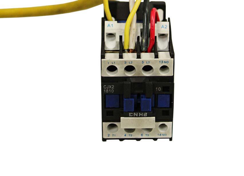
18 O. Install the Electrical System Connect the power source on the data plate of Power Unit. Operating voltage range 208v-230v. Remove the short Pig Tail wire connected to the AC contactor terminals. This wire was used to test the motor after production. ATLAS Single phase motor Please Note: This motor is powered by Alternating Current and the terminals on the AC contactor are not wire color specific. There are no positive or negative terminals. 1. Connect the two power supply (incoming) wires (black & white) to terminals on the AC contactor marked L2 & L3. 2. Connect the two motor wires to terminals on the AC contactor marked T2, T3. These wires are already connected from the factory. 3. Connect the short wire A2 to L3 on the AC contactor. This wire is already connected from the factory. AC CONTACTOR 16

19 17

20 IV.EXPLODED VIEW Model BP Fig
21 Cylinders Fig

 Running capacitor Start capacitor Protective ring")

22 Illustration of hydraulic valve for ATLAS hydraulic power unit ATLAS manual power unit, 220V/60HZ, Single phase (See Fig.29) Running capacitor Start capacitor Protective ring Relief valve Oil return port Oil Outlet Release valve Check valve Handle for Release valve Throttle valve Fig. 29 ATLAS MANUAL POWER UNIT 220V/60HZ/1Phase Fig


23 V. TEST RUN 1. Adjust the equalizing cables (See Fig. 31) Use wrench to hold the cable fitting, meanwhile Use a ratchet to tighten the cable nut. Make sure the cables have the same tension First Safety so the two carriages lift at the same time. lock Replace the covers on the carriages. If the carriages do not lift at the same time, tighten the cable nut on the lower of the two carriages. Cable nut Fig Adjust safety cable Lift the carriages and lock at the same height, pull the safety cable and then release a little, and then tighten the cable nuts. Make sure the safety locks click at the same time. 3. Adjust the lower speed (Only for ATLAS power unit) (See Figure 32) You can adjust the lowering speed of the lift if necessary: Loosen the locking nut on the throttle valve, and then turn the throttle valve clockwise to decrease the lowering speed, or counterclockwise to increase the lowering speed. Do not forget to tighten the locking nut after the lower speed adjustment has been completed. Throttle Valve Fixing Nut Clockwise to decrease the lowering speed Counterclockwise to increase the lowering speed Fig
24 4. Test with load After finishing the above adjustments, test run the lift with load. Run the lift in low position for several times first. Make sure the lift can raise and lower at the same time so the Safety Device can lock and release. Test run the lift to the top completely. The above adjustments may need to be repeated. NOTE: If the lift vibrates on the way up with a load, lubricate all pulley shafts and wear blocks. If the lift vibrates on the way down, the cylinders need to run all of the way up and down to evacuate any residual air. Figure 33 Hydraulic System VI. OPERATION INSTRUCTIONS Please read the safety tips carefully before operating the lift To lift vehicle 1. Keep clean of site near the lift; 2. Position lift arms to the lowest position; 3. To shortest lift arms; 4. Open lift arms; 5. Position vehicle between columns; 6. Move arms to the vehicle s lifting point; Note: The four lift arms must at the same time contact the vehicle s lifting point where manufacturers recommended 22
25 7. Press the UP button until the lift pads contact underside of vehicle totally. Recheck to make sure vehicle is secure; 8. Continue to raise the lift slowly to the desired working height, ensuring the balance of vehicle; 9. Push lowering handle to lower lift onto the nearest safety. The vehicle is ready to repair. To lower vehicle 1. Be sure clear of around and under the lift, only leaving operator in lift area; 2. Press the button of UP to raise the vehicle slightly, and then release the safety device, lower vehicle by pushing lowering handle. 3. Open the arms and position them to the shortest length; 4. Drive away the vehicle. 5. Turn off the power. VII. MAINTENANCE SCHEDULE Monthly: 1. Re-torque the anchor bolts to150 lbs.; 2. Check all connectors, bolts and pins to insure proper mounting; 3. Lubricate cable with lubricant; 4. Make a visual inspection of all hydraulic hoses/lines for possible wear or leakage; 5. Check Safety device and make sure it is in good condition; 6. Lubricate all Rollers and Pins with 90wt. Gear oil or equivalent; Note: All anchor bolts should take full torque. If any of the bolts do not function for any reason, DO NOT use the lift until the bolt has been replaced. Every six months: 1. Make a visual inspection of all moving parts for possible wear, interference or damage. 2. Check and adjust as necessary, equalizer tension on the cables to insure level lifting. 3. Check columns for plumb. 4. Check Rubber Pads and replace as necessary. 5. Check Safety device and make sure it is in good condition. 23
26 VIII.TROUBLE SHOOTING TROUBLE CAUSE REMEDY 1. Button does not work 2. Wiring connections are not in good 1. Replace button 2.Repair all wiring connections Motor does not run condition 3. Motor burned out 4. AC contactor in damage 3. Repair or replace motor 4. Replace or replace Motor runs but the lift is not raised 1. Motor runs in reverse rotation 2. Gear pump out of operation 3. Release valve in damage 4. Relief valve or check valve in damage 5. Low oil level 1.Reverse two power wire 2.Repair or replace 3. Repair or replace 4.Repair or replace 5.Fill tank Lift does not stay up 1. Release valve out of work 2. Relief valve or check Valve leakage 3. Cylinder or fttings leaks Repair or replace Lift raises slowly 1. Oil line is jammed 2. Motor running on low voltage 3. Oil mixed with air 4. Gear Pump leaks 5. Overload lifting 1. Clean the oil line 2. Check electrical system 3. Fill tank 4. Replace pump 5. Check load Lift can not lower 1. Safety device are locking. 2. Release valve in damage 3. Safety cable broken 4. Oil system is jammed 1. Release the safeties 2. Repair or replace 3. Replace 4. Clean the oil system 24
27 IX. PARTS LIST FOR MODEL BP Item Part# Description Qty. Note Power side column Plastic Pulley Snap Ring Safety Cover Cup Head Bolt Washer A Hex Nut Manual Power Unit Safety Pin Safety Spring Power side Safety Lock Hair Pin Safety Block (Main) Hex Bolt Rubber Ring Self locking nut Floor Cover A Rubber Pad Assy. 4 18A Socket bolt 4 18B Rubber Pad 4 18C B Rubber Pad Frame Lock Washer Hex Bolt Small Pulley Self locking nut A Chain Connector Chain Hydraulic Cylinder Pin For Chain Pulley A Bronze bush for Chain Pulley Chain pulley Split Pin Chain Pulley Assy Powerside Carriage Slider Carriage Plastic Cover Protective Rubber Self-tapping Screw Plastic Ball Hex Nut Washer 10 25
28 Item Part# Description Qty. Note A Arm lock Limit Ring Arm Lock Bar Hair Pin Spring Protective Rubber Set A Lifting Arm - Front Right 1 45A Outer Arm - Front Right 1 45B Middle Arm - Front Right 1 45C A Inner Arm - Front Right A Lifting Arm - Front Left 1 46A Outer Arm - Front Left 1 46B Middle Arm - Front Left 1 46C A Inner Arm - Front Left A Lifting Arm - Rear Left 1 47A Outer Arm - Rear Left 1 47B A Inner Arm - Rear Left Offside Carriage A Lifting Arm - Rear Right 1 49A Outer Arm - Rear Right 1 49B B Inner Arm - Rear Right Moon Gear Washer Lock Washer Socket Bolt Arm Pin Connecting Bar Hex Bolt Hex Bolt Top plate Big Pulley A Bronze Bush For Pulley Offside column Plastic Pulley Offside Safety Lock Coupling Safety Block (Secondly ) Socket Bolt Snap Ring B Stackable Adapter (1.5 ) B Stackable Adapter (2.5 ) B Stackable Adapter (5 ) Anchor bolt 12 26
29 Item Part# Description Qty. Note Shim Cable Cable Nut T-Fitting Oil Hose Fitting Oil Hose Fitting for Power Unit Safety Cable Parts Box 1 Parts For Hydraulic Cylinder Piston Rod Piston O-Ring Support Ring Y-Ring O-Ring Hex Nut Adjustment Tube Dust Ring O-Ring Head Cap Bleeding Plug O-Ring Bore Weldment 2 27
30 Parts For ATLAS Manual Power Unit 220V/60HZ/1Phase Item Part# Description Qty. Note 201A A Motor 1 201A Protective Ring 1 201A AC contactor 1 201A A Motor Connecting Shaft 1 201A A Valve Body 1 201A A Relief Valve 1 201A Throttle valve 1 201A A Lock Washer 4 201A A Socket Bolt 4 201A A Inlet Pipe 1 201A A O-Ring 1 201A A Filter 1 201A A Socket bolt 4 201A A Reservoir (10 liter) 1 201A A Cup Head Bolt with washer 4 201A A Cover of Capacitor 2 201A A Start Capacitor 1 201A-17A B Run Capacitor 1 201A A Rubber Gasket 2 201A A Cup Head Bolt with washer 2 201A A Cover of Motor Terminal Box 1 201A A Push Button 1 201A A Oil Return Port 1 201A A Oil Outlet 1 201A A Check Valve 1 201A A Release Valve 1 201A A Handle For Release Valve 1 201A A Washer 1 201A A Hex Nut 1 201A A Gear Pump 1 201A A Oil Return Pipe 1 201A A Filler Cap 1 28
CONTENTS. Product Features and Specifications...1. Installation Requirement Steps of Installation.. 5. Exploded View Test Run...
 CONTENTS Product Features and Specifications...1 Installation Requirement... 4 Steps of Installation.. 5 Exploded View...21 Test Run...26 Operation Instruction...27 Maintenance... 28 Trouble Shooting...
Read this entire manual before operation begins.
 Read this entire manual before operation begins. Record below the following information which is located on the serial number data plate. Serial No. Model No. Date of Installation Contents Specifications.............
CONTENTS. Product Features and Specifications Installation Requirement Steps of Installation 4. Exploded View Test Run...
 CONTENTS Product Features and Specifications... 1 Installation Requirement... 3 Steps of Installation 4 Exploded View... 14 Test Run... 16 Operation Instruction... 19 Maintenance... 20 Trouble Shooting...
CONTENTS. Product Features and Specifications Installation Requirement Installation Exploded View Operation Instruction...
 1 CONTENTS Product Features and Specifications... 3 Installation Requirement... 5 Installation... 6 Exploded View... 20 Test... 22 Operation Instruction... 25 Maintenance... 26 Trouble Shooting... 27 Parts
Read this entire manual before operation begins.
 Read this entire manual before operation begins. Record below the following information which is located on the serial number data plate. Serial No. Model No. Date of Installation Contents Specifications.............
Read this entire manual before operation begins.
 Read this entire manual before operation begins. Record below the following information which is located on the serial number data plate. Serial No. Model No. Date of Installation Contents Specifications.............
CONTENTS. Product Features and Specifications...1. Installation Requirement...3. Steps of Installation...4. Exploded View Test Run...
 TP10AS 2-POST LIFT CONTENTS Product Features and Specifications...1 Installation Requirement...3 Steps of Installation...4 Exploded View...24 Test Run....28 Operation Instruction...29 Maintenance...30
Atlas PV-9WP Addendum
 Atlas PV-9WP Addendum 9,000 lb. Capacity Two-Post Overhead Lift The Atlas PV-9WP above ground hoist is 6 inches wider than the Atlas PV-9P, giving it an overall width of 141 (11 9 ) and a drive thru width
Read this entire manual before operation begins.
 Read this entire manual before operation begins. Record below the following information which is located on the serial number data plate. Serial No. Model No. Date of Installation Contents Specifications.............
Read this entire manual before operation begins.
 Rev. 12/12/2017 Read this entire manual before operation begins. Record below the following information which is located on the serial number data plate. Serial No. Model No. Date of Installation Contents
Read this entire manual before operation begins.
 Read this entire manual before operation begins. Record below the following information which is located on the serial number data plate. Serial No. Model No. Date of Installation Contents Specifications.............
30-SS1203A 12,000 LB CAPACITY SCISSOR ALIGNMENT LIFT INSTALLATION AND SERVICE MANUAL P/N:
 WITH STRENGTH 30-SS1203A 12,000 LB CAPACITY SCISSOR ALIGNMENT LIFT INSTALLATION AND SERVICE MANUAL P/N: 420-02553 CONTENTS Product Features and Specifications...1 Installation Requirement...3 Steps of
Read this entire manual before operation begins.
 Read this entire manual before operation begins. Record below the following information which is located on the serial number data plate. Serial No. Model No. Date of Installation Contents Specifications.............
Installation/Operation/Service Manual
 TLX12/TLX12A Installation/Operation/Service Manual CONTENTS Product Features and Specifications...1 Installation Requirement...3 Steps of Installation...4 Exploded View...23 Test Run...28 Operation Instruction...29
ATD2P11BS. Two-Post Clear Floor Bi-Symmetric Automotive Lift. Installation & Operation Manual. 11,000 lbs. Capacity. (2,750 lbs.
 Two-Post Clear Floor Bi-Symmetric Automotive Lift 11,000 lbs. Capacity (2,750 lbs. Max per Arm) Installation & Operation Manual 1. Safety Information 1.1 Note, Caution and Warning 1.2 Important Information
Lifting height 5.5" - 72" with adapters " Height overall 165" Width between columns 122" Drive through 109" Width overall 151.
 Model Number TP12KC-D Capacity 12,000 lbs. Lifting height 5.5" - 72" with adapters 79.625" Height overall 165" Width between columns 122" Drive through 109" Width overall 151.125" Arm extension 37.5" -
Models PR-12F PR-12C PR-15C SURFACE MOUNTED TWO-POST LIFTS INSTALLATION AND OPERATION MANUAL
 Forward this manual to all operators. Failure to operate this equipment as directed may cause injury. INSTALLATION AND OPERATION MANUAL SURFACE MOUNTED TWO-POST LIFTS Models PR-12F PR-12C PR-15C Keep this
TWO POST LIFT INSTALLATION AND OWNERS MANUAL
 TWO POST LIFT INSTALLATION AND OWNERS MANUAL DP15, DP15-2 Capacity 15,000 lbs. 1. TABLE OF CONTENTS 2. Important Information.. 2 3. Section 1 Owner s Manual Safety Instructions... 3 Monthly Maintenance...
ASSEMBLY & OPERATION INSTRUCTION MANUAL
 LR-26-PAD 6000 lb Capacity Low-Rise Pad Lift ASSEMBLY & OPERATION INSTRUCTION MANUAL 6,000 LB. LOW-RISE PAD LIFT Easy frame lifting on padded runways. Great for wheel and brake work, tire and wheel changing
Model FP14KO-A Wheel alignment & Open Front Four-Post Lift
 Model FP14KO-A Wheel alignment & Open Front Four-Post Lift ( 14000LBS / 6300Kg Capacity) ASSEMBLY & OPERATION INSTRUCTIONS ( Series T1) 2009.7. INTRODUCTION Model FP14KO-A is a four-post lift is used in
ASSEMBLY & OPERATION INSTRUCTION MANUAL
 Sliding Bridge Jack 3,500 lbs. Capacity ASSEMBLY & OPERATION INSTRUCTION MANUAL TABLE OF CONTENTS Specifications... 2 Description & Features... 3 Installation Instructions... 4 Safety Instructions... 4
Model SL-12K-A SCISSOR LIFT. wheel alignment model. (11000 LBS / 5000Kg Capacity) INSTALLATION & OPERATION INSTRUCTION (SECOND EDITION)
 INSTALLATION & OPERATION INSTRUCTION (SECOND EDITION)") Model SL-12K-A SCISSOR LIFT wheel alignment model (11000 LBS / 5000Kg Capacity) INSTALLATION & OPERATION INSTRUCTION (SECOND EDITION) 2007. 6. CONTENTS Chapter 1 Introduction & Specifications ---------------------------------------
Model SL-12K-A SCISSOR LIFT wheel alignment model (11000 LBS / 5000Kg Capacity) INSTALLATION & OPERATION INSTRUCTION (SECOND EDITION) 2007. 6. CONTENTS Chapter 1 Introduction & Specifications ---------------------------------------
TP15KC-KX Two-Post Clear Floor Lift
 TP15KC-KX Two-Post Clear Floor Lift (Symmetric) 15,000 lbs. Capacity (3,750 lbs. Max per Arm) ASSEMBLY & OPERATION INSTRUCTION MANUAL Feb. 2017 IMPORTANT NOTES READ THE INSTALLATION AND OPERATION MANUAL
TWO POST LIFT INSTALLATION AND OWNERS MANUAL. January 2008 rev. E I MAN
 TWO POST LIFT INSTALLATION AND OWNERS MANUAL DP15, DP15-2 Capacity 15,000 lbs. January 2008 rev. E 1. TABLE OF CONTENTS 2. Important Information.. 2 3. Section 1 Owner s Manual Safety Instructions... 3
Installation Instructions Capacity 10,000 lbs. (100 Series Lift)
") Installation Instructions Capacity 10,000 lbs. (100 Series Lift) IMPORTANT Reference ANSI/ALI ALIS, Safety Requirements for Installation and Service of Automotive Lifts before installing lift. OPERATING
Installation Instructions Capacity 10,000 lbs. (100 Series Lift) IMPORTANT Reference ANSI/ALI ALIS, Safety Requirements for Installation and Service of Automotive Lifts before installing lift. OPERATING
ATTENTION. 1. Do not attempt to use the power unit to extend your cylinder. This must be done manually.
 NSS8XLT Installation Manual ATTENTION By following the instructions in this manual you can save yourself much time, frustration and money. The installation of your lift will take 4-5 hours. Do not rush.
OPERATION AND PARTS MANUAL
 OPERATION AND PARTS MANUAL MODEL NUMBER : PART NUMBER : GTL 1110 1900-0510 SERIAL NUMBER : BAYNE MACHINE WORKS, INC. PHONE: (864) 288-3877 910 FORK SHOALS ROAD TOLL FREE: (800) 535-2671 GREENVILLE S.C.,
WHIP INDUSTRIES, INC.
 WHIP INDUSTRIES, INC. WFP30R, WFP30R-E & WFP30R-EE STD., EXT. & E-EXT. 30,000 LBS CAPACITY FOUR POST ABOVE GROUND LIFT INSTALLATION INSTRUCTIONS & MANUAL WHIP INDUSTRIES, INC 3010 S MAIN ST. FORT WORTH,
ATD-2P9A 9,000 lbs. Two Post Clear Floor Lift Owner s Manual
 ATD-2P9A 9,000 lbs. Two Post Clear Floor Lift Owner s Manual Features: Specifications: IMPORTANT NOTES READ THE INSTALLATION AND OPERATION MANUAL IN ITS ENTIRETY BEFORE ATTEMPTING TO INSTALL THE LIFT.
HEAVY DUTY TROLLEY JACK. Operation Manual
 HEAVY DUTY TROLLEY JACK 4T Operation Manual Make sure to read and fully understand the instruction manual before using this product and keep the manual properly 1 General Description Product Description
Floor Plate Style Lift And Overhead Beam Style Lift. Two Post Lift
 Floor Plate Style Lift And Overhead Beam Style Lift 9,000 POUND Two Post Lift ASSEMBLY & OPERATION INSTRUCTION TABLE OF CONTENTS Important Note Page 3 Definition Page 4 Preparation and General Information
OPERATION AND PARTS MANUAL
 OPERATION AND PARTS MANUAL MODEL NUMBER : PART NUMBER : GRL 1110 1900-0540 SERIAL NUMBER : BAYNE MACHINE WORKS, INC. PHONE: 864.288.3877 910 FORK SHOALS ROAD TOLL FREE: 800.535.2671 GREENVILLE SC, 29605
INSTALLATION MANUAL & OPERATION INSTRUCTIONS. OVERHEAD CAR LIFT 2-POST LIFT AUTO HOIST APlusLift HW-10KOH
 INSTALLATION MANUAL & OPERATION INSTRUCTIONS OVERHEAD CAR LIFT 2-POST LIFT AUTO HOIST APlusLift HW-10KOH 1 READ THIS MANUAL COMPLETELY BEFORE INSTALLING LIFT!!! DISTRIBUTED BY: Songa Enterprises LLC 8512
Service Jacks. Operating Instructions & Parts Manual. Model Number. Capacity 4 Ton 4 Ton Air/ Manual 10 Ton 10 Ton Air/ Manual HW93657/ HW93660
 Service Jacks Operating Instructions & Parts Manual Model Number HW93657 HW93667 HW93660 HW93662 Capacity 4 Ton 4 Ton Air/ Manual 10 Ton 10 Ton Air/ Manual Made in North America HW93657/ HW93660 HW93667/
INSTALLATION & OPERATION MANUAL
 Two-Post Clear Floor Lift (Asymmetric) 9,000 lbs. Capacity (2,250 lbs. Max per Arm) INSTALLATION & OPERATION MANUAL IMPORTANT NOTES READ THE INSTALLATION AND OPERATION MANUAL IN ITS ENTIRETY BEFORE ATTEMPTING
Index. 1. Important safety instructions Overview of the lift Installation instructions Operation instructions 8-9
 2 Index 1. Important safety instructions 4-5 1.1 Safety Warnings 1.2 Qualified personnel 1.3 Safety 1.4 Warning signs 2. Overview of the lift 6 2.1 General descriptions 2.2 Technical data 2.3 Construction
MODEL MA4210 Installation and Operation Manual Important:
 MODEL MA4210 Installation and Operation Manual Important: This manual contains specific cautionary statements relative to worker safety. Read this manual thoroughly and follow as directed. It is impossible
High Lift Transmission Jack
 655 Eisenhower Drive Owatonna, MN 55060 USA Phone: (507) 455-7000 Tech. Serv.: (800) 533-6127 Fax: (800) 955-8329 Order Entry: (800) 533-6127 Fax: (800) 283-8665 International Sales: (507) 455-7223 Fax:
9,000 POUND TWO-COLUMN AUTOMOTIVE LIFT Model: NW-2-9KFP MANUAL
 9,000 POUND TWO-COLUMN AUTOMOTIVE LIFT Model: NW-2-9KFP MANUAL 1 9,000 POUND CAPACITY MODEL: NW-2-9KFP TWO-COLUMN AUTOMOTIVE LIFT READ THIS ENTIRE MANUAL BEFORE OPERATION BEGINS RECORD BELOW THE FOLLOWING
Model FP12K-K Flat Deck Four-Post Lift
 Model FP12K-K Flat Deck Four-Post Lift (12,000LBS Capacity) ASSEMBLY & OPERATION INSTRUCTION 2006.4. TABLE OF CONTENTS Important Note--------------------------------------------------------------------------------Page
QJY245DS~DA. Two Post Lift Installation & Adjustment Manual
 QJY245DS~DA Two Post Lift Installation & Adjustment Manual Table of Contents 1. Warning 2 2. Summary 2 3. Use 2 4. Mainly technology parameter 2 5. Basic structure of the production 3 6. Safety device
TWO POST LIFT INSTALLATION AND OWNERS MANUAL Capacity 10,000 lbs.
 TWO POST LIFT INSTALLATION AND OWNERS MANUAL Capacity 10,000 lbs. May 2009 All rights reserved. CO7378.2 IN60005 Rev. - 5/7/2009 TABLE OF CONTENTS Important Information...2 Section 1 Owner s Manual Safety
Models: SURFACE MOUNTED FOUR-POST LIFTS INSTALLATION AND OPERATION MANUAL
 Forward this manual to all operators. Failure to operate this equipment as directed may cause injury. INSTALLATION AND OPERATION MANUAL SURFACE MOUNTED FOUR-POST LIFTS Models: FL-18 BP-18 BP-27/ BP-27A
Read this entire manual before operation begins.
 Read this entire manual before operation begins. Record below the following information which is located on the serial number data plate. Serial No. Model No. Date of Installation Contents Specifications.............
Hand Pallet Truck NC. Operation Manual
 Hand Pallet Truck -------NC Operation Manual Operation Manual 1 Application Range This product is suitable for using in rated load of up to 5500lbs. This PL5500HD is the perfect jack for handling palletized
Installation Instructions Capacity 10,000 lbs. DP10 (200 Series Lift)
") Installation Instructions Capacity 10,000 lbs. DP10 (200 Series Lift) IMPORTANT Reference ANSI/ALI ALIS, Safety Requirements for Installation and Service of Automotive Lifts before installing lift. OPERATING
Installation Instructions Capacity 10,000 lbs. DP10 (200 Series Lift) IMPORTANT Reference ANSI/ALI ALIS, Safety Requirements for Installation and Service of Automotive Lifts before installing lift. OPERATING
MSC-6KLP Low Profile Mobile Single Column Lift. 6,000 lb. Capacity (1,500 lbs. Max Capacity per Arm) Installation & Operation Manual
 Installation & Operation Manual") Low Profile Mobile Single Column Lift 6,000 lb. Capacity (1,500 lbs. Max Capacity per Arm) Installation & Operation Manual INDEX PREFACE-------------------------------------------------------------------------------
Low Profile Mobile Single Column Lift 6,000 lb. Capacity (1,500 lbs. Max Capacity per Arm) Installation & Operation Manual INDEX PREFACE-------------------------------------------------------------------------------
TWO POST LIFT INSTALLATION AND OWNERS MANUAL Capacity 10,000 lbs.
 TWO POST LIFT INSTALLATION AND OWNERS MANUAL Capacity 10,000 lbs. October 2012 by Vehicle Service Group All rights reserved. CO8347 IN60009 Rev. H 10/18/2012 TABLE OF CONTENTS Important Information...2
1988 Chevrolet Pickup V SUSPENSION - FRONT (4WD)' 'Front Suspension - "V" Series 1988 SUSPENSION - FRONT (4WD) Front Suspension - "V" Series
' 'Front Suspension - V Series 1988 SUSPENSION - FRONT (4WD) Front Suspension - V Series") 1988 SUSPENSION - FRONT (4WD) Front Suspension - "V" Series DESCRIPTION NOTE: Vehicle serial numbers used in this article has been abbreviated for common reference to Chevrolet and GMC models. Chevrolet
1988 SUSPENSION - FRONT (4WD) Front Suspension - "V" Series DESCRIPTION NOTE: Vehicle serial numbers used in this article has been abbreviated for common reference to Chevrolet and GMC models. Chevrolet
9,000 POUND TWO-COLUMN AUTOMOTIVE LIFT. Model: NW-2-9KACD MANUAL
 9,000 POUND TWO-COLUMN AUTOMOTIVE LIFT Model: NW-2-9KACD MANUAL 1 9,000 POUND CAPACITY MODEL: NW-2-9KACD TWO-COLUMN AUTOMOTIVE LIFT READ THIS ENTIRE MANUAL BEFORE OPERATION BEGINS RECORD BELOW THE FOLLOWING
Air Assist Bottle Jack Max. Capacity: 12 Tons (4313C) & 20 Tons (4321C) Operating Range: psi
 & 20 Tons (4321C) Operating Range: psi") Form No. 545742 Parts List and Operating Instructions for: 4313C 4321C Air Assist Bottle Jack Max. Capacity: 12 Tons (4313C) & 20 Tons (4321C) Operating Range: 40 150 psi 45 44 43 42 41 40 39 22 1 37 28
Form No. 545742 Parts List and Operating Instructions for: 4313C 4321C Air Assist Bottle Jack Max. Capacity: 12 Tons (4313C) & 20 Tons (4321C) Operating Range: 40 150 psi 45 44 43 42 41 40 39 22 1 37 28
Operating Instructions
 Operating Instructions Parts List Hand Pallet Truck Note: Operator MUST read and understand this operating instructions before use this Hand Pallet Truck. Thank you for using our pallet truck. Your pallet
HYDRAULICS. TX420 & & lower. Hydraulic Tandem Pump Removal. 4. Remove the LH side panel (Fig. 0388).
.") TX420 & 425 240000299 & lower 4. Remove the LH side panel (Fig. 0388). Hydraulic Tandem Pump Removal Note: Cleanliness is a key factor in a successful repair of any hydraulic system. Thoroughly clean all
TX420 & 425 240000299 & lower 4. Remove the LH side panel (Fig. 0388). Hydraulic Tandem Pump Removal Note: Cleanliness is a key factor in a successful repair of any hydraulic system. Thoroughly clean all
Sachs shock manual. ( ) 2 & 4 Stroke RR Enduro. ( ) RS Dual Sport
 2 & 4 Stroke RR Enduro. ( ) RS Dual Sport") Sachs shock manual (2013 2015) 2 & 4 Stroke RR Enduro (2014-2015) RS Dual Sport 1 Introduction The procedures in this manual must take place in a clean environment using professional tools and some specific,
Sachs shock manual (2013 2015) 2 & 4 Stroke RR Enduro (2014-2015) RS Dual Sport 1 Introduction The procedures in this manual must take place in a clean environment using professional tools and some specific,
Installation Instructions
 Preparing your vehicle to install your brake system upgrade 1. Rack the vehicle. 2. If you don t have a rack, then you must take extra safety precautions. 3. Choose a firmly packed and level ground to
1995 Mitsubishi Montero LS. Ensure timing marks are aligned. Mark timing belt direction of rotation.
 TIMING BELT NOTE: Ensure timing marks are aligned. Mark timing belt direction of rotation. Removal 1. Disconnect negative battery cable. Drain engine coolant. Remove engine coolant reservoir tank, fan
INSTALLATION MANUAL. Table of Contents
 INSTALLATION MANUAL Table of Contents. Precaution. Structure and working Principle... Structure Schematic Diagram..... Main Structure and Principle of the Equipment.3 3. Tools for installation and adjustment..4
CALIFORNIA TRIMMER MOWER MAINTENANCE MANUAL
 CALIFORNIA TRIMMER MOWER MAINTENANCE MANUAL 2 Table of Contents Section 1: General Information Page Handle Assembly Instructions 4 Maintenance All Models 6 Oil Change Procedures All Models 9 Height Adjustment
Read this entire manual before operation begins.
 Revised 9/5/2018 Read this entire manual before operation begins. Record below the following information which is located on the serial number data plate. Serial No. Model No. Date of Installation Contents
Side Kick 2. Installation Instructions & Parts Lists. Attention Dealers: Please give this owners manual to the customer when the product is delivered.
 Serving the Truck & Trailer Industry Since 1944 Side Kick 2 Installation Instructions & Parts Lists Attention Dealers: Please give this owners manual to the customer when the product is delivered. Call
INSTALLATION and OPERATION MANUAL
 INSTALLATION and OPERATION MANUAL EELR349A // EELR351A 10,000 10,000 LB. LB. (SYMMETRICAL) READ THIS INSTRUCTION MANUAL THOROUGHLY BEFORE INSTALLING, OPERATING, SERVICING OR MAINTAINING THE LIFT. SAVE
PARTS MANUAL THIS PAGE INTENTIONALLY LEFT BLANK. Ag-Bag International, Ltd. G7000 June Appendix A
 The parts manual is organized into groups, it is designed to make the locating of parts easier. The exploded drawings also show assembly paths. All parts listed are available from your authorized Ag-Bag
PSR-HP-3000 MANUAL HAND PUMP INTERNAL LIQUID CAPICITY MAXIMUM OUTPUT PRESSURE PsiG (BarG) GALLONS (LITERS) 3000 (207) 5 (19)
 GALLONS (LITERS) 3000 (207) 5 (19)") PAGE 1 OF 6 P-SERIES HAND PUMP OPERATING INSTRUCTIONS WARNING: PRESSURE TESTING IS INHERENTLY DANGEROUS. STRICT ADHERENCE TO THESE OPERATING INSTRUCTIONS AND INDUSTRY SAFETY PRACTICES COULD PREVENT INJURY
PAGE 1 OF 6 P-SERIES HAND PUMP OPERATING INSTRUCTIONS WARNING: PRESSURE TESTING IS INHERENTLY DANGEROUS. STRICT ADHERENCE TO THESE OPERATING INSTRUCTIONS AND INDUSTRY SAFETY PRACTICES COULD PREVENT INJURY
Model FP14KA-C Alignment Four-Post Lift
 Model FP14KA-C Alignment Four-Post Lift (14000 LBS Capacity) ASSEMBLY & OPERATION INSTRUCTION 2006.4. TABLE OF CONTENTS Important Note--------------------------------------------------------------------------------Page
GH-BETTIS SERVICE INSTRUCTIONS DISASSEMBLY & REASSEMBLY FOR MODELS HD521-M4, HD721-M4 AND HD731-M4 DOUBLE ACTING SERIES PNEUMATIC ACTUATORS
 GH-BETTIS SERVICE INSTRUCTIONS DISASSEMBLY & REASSEMBLY FOR MODELS HD521-M4, HD721-M4 AND HD731-M4 DOUBLE ACTING SERIES PNEUMATIC ACTUATORS WITH HYDRAULIC CONTROL PACKAGE PART NUMBER: SE-023 REVISION:
INSTRUCTIONS AND PARTS LIST FOR Models 8-025, 8-050, 8-075, and Elec-Draulic II Presses
 INSTRUCTIONS AND PARTS LIST FOR Models 8-025, 8-050, 8-075, and 8-150 Elec-Draulic II Presses SETTING UP THE PRESS FOR OPERATION For shipping convenience some of the parts are not assembled. Assemble these
INSTALLATION and OPERATION MANUAL
 INSTALLATION and OPERATION MANUAL 10K 2N1 2 POST V-SERIES SV210S - R/B/M,1/3 D210S - R/B/M,1/3 READ and SAVE THIS INSTRUCTION MANUAL JUNE 2007 6-3255 Table of Contents 1.0 SAFETY AND OPERATING INSTRUCTIONS...3
1. Perform fuel pressure release procedure. (Refer to FUEL SYSTEM/FUEL DELIVERY - STANDARD PROCEDURE).
.") 1Search TIMING BELT 2005 Chrysler Pacifica 3.5L Eng Base FRONT TIMING BELT COVER REMOVAL 1. Perform fuel pressure release procedure. (Refer to FUEL SYSTEM/FUEL DELIVERY - STANDARD PROCEDURE). 2. Disconnect
1Search TIMING BELT 2005 Chrysler Pacifica 3.5L Eng Base FRONT TIMING BELT COVER REMOVAL 1. Perform fuel pressure release procedure. (Refer to FUEL SYSTEM/FUEL DELIVERY - STANDARD PROCEDURE). 2. Disconnect
TURRET HEAD INSTALLATION
 INSTALLATION INSTRUCTIONS: TURRET HEAD INSTALLATION THE HANGER BRACKETS WELDED ON THE BACK OF THE ATTACHMENT CONFORM TO THE SPECIFICATIONS OF THE MAST. INSTALL THE MAST ROLLER BEARING KIT ACCORDING TO
OPERATORS MANUAL/INSTRUCTIONS/PARTS & SERVICE FOR MANUAL & ELECTRIC
 OPERATORS MANUAL/INSTRUCTIONS/PARTS & SERVICE FOR MANUAL & ELECTRIC TABLE OF CONTENTS SAFETY DELIVERY INSPECTION OPERATION 4 MAINTENANCE 5 TROUBLE SHOOTING 5 PARTS 6-15 Frame Scissor Assembly 6-7 Thrust
BRAKE SYSTEM Nissan 240SX DESCRIPTION BRAKE BLEEDING * PLEASE READ FIRST * BLEEDING PROCEDURES ADJUSTMENTS BRAKE PEDAL HEIGHT SPECS TABLE
 BRAKE SYSTEM 1990 Nissan 240SX 1990 BRAKE SYSTEMS Nissan Disc & Drum Axxess, Maxima, Pathfinder, Pickup, Pulsar NX, Sentra, Stanza, 240SX, 300ZX DESCRIPTION All brake systems are hydraulically operated
INSTALLATION AND MAINTENANCE OF TOP LOADING ARM
 INSTALLATION AND MAINTENANCE OF TOP LOADING ARM D TABLE OF CONTENTS 1. INTRODUCTION 04 2. SPECIFICATION OF THE REDLANDS LOADING ARM 04 3. INSTALLING THE LOADING ARM 3.1. Installation Procedures 05 4.
Maintenance Information
 16575128 Edition 2 May 2014 Air Grinder, Sander or Polisher 77A Series Maintenance Information Save These Instructions Product Safety Information Failure to observe the following warnings, and to avoid
INSTALLATION and OPERATION MANUAL
 INSTALLATION and OPERATION MANUAL AC2012S 12,000 12,000 LB. LB. (SYMMETRICAL) READ and SAVE THIS INSTRUCTION MANUAL P.O. Box 15540 Richmond, VA 23227 804-798-8922 www.accu-turn.com 1-800-551-2228 APR 2004
Installation Instructions
 Installation Instructions 2-Post Capacity 12,000 lbs. OPERATING CONDITIONS Lift is not intended for outdoor use and has an operating ambient temperature range of 41-104 F (5-40 C) IMPORTANT Reference ANSI/ALI
Instruction Manual. High Lift Hand Truck
 Instruction Manual High Lift Hand Truck Note: The Owner/Operator must read carefully and understand all the information presented here before operation. CONTENT 1. Specification. 2 2. Safety Instructions...
GH-BETTIS OPERATING & MAINTENANCE INSTRUCTIONS DISASSEMBLY & ASSEMBLY FOR THE T80X-M4-S DOUBLE ACTING SERIES HYDRAULIC ACTUATORS
 GH-BETTIS OPERATING & MAINTENANCE INSTRUCTIONS DISASSEMBLY & ASSEMBLY FOR THE T80X-M4-S DOUBLE ACTING SERIES HYDRAULIC ACTUATORS -S INDICATES CYLINDERS ARE IN TANDEM PART NUMBER: 100121 REVISION "A" ECN
MODEL SCA Installation and Operation Manual Important:
 MODEL SCA Installation and Operation Manual Important: This manual contains specific cautionary statements relative to worker safety. Read this manual thoroughly and follow as directed. It is impossible
STACKER INSTRUCTION MANUAL
 STACKER INSTRUCTION MANUAL The Mobile Stackers are lifting devices featuring easy, flexible, reliable and safe operation suitable for transportation of loads in such applications as warehouses, manufacturing
Ideal Installation. I & M Mark 67 (1/2 6 ) Control Line. Installation & Maintenance Instructions for Mark 67 Pressure Regulators
 Control Line. Installation & Maintenance Instructions for Mark 67 Pressure Regulators") I & M Mark (/ ) 0 Wasson Road Cincinnati, OH 0 USA Phone --00 Fax -8-00 info@richardsind.com www.jordanvalve.com Installation & Maintenance Instructions for Mark Pressure Regulators Warning: Jordan Valve
I & M Mark (/ ) 0 Wasson Road Cincinnati, OH 0 USA Phone --00 Fax -8-00 info@richardsind.com www.jordanvalve.com Installation & Maintenance Instructions for Mark Pressure Regulators Warning: Jordan Valve
REMOVAL & INSTALLATION
 REMOVAL & INSTALLATION CAUTION: This application is an interference engine. Do not rotate camshaft or crankshaft when timing belt is removed, or engine damage may occur. TIMING BELT Removal 1. Raise and
1. GENERAL SPECIFICATIONS 2. TO ATTACH DRAW-BAR TO PUMP UNIT
 Thank you for using our pallet truck. Your pallet truck is made of high quality steel and is designed for the horizontal lifting and transport of loads on a pallet or standardized containers on a level,
INTEGRAL POWER STEERING GEAR FORD Applies to F-100 F-350 (4X2), F-150 F-250 (4X4) And Bronco
, F-150 F-250 (4X4) And Bronco") Rockcrawler Steering Shop Manual page1 The following is from the Ford 1978 Truck Shop Manual, Volume 1 Chassis. It is provided here as a courtesy to classic Ford owners who would like to perform their
Rockcrawler Steering Shop Manual page1 The following is from the Ford 1978 Truck Shop Manual, Volume 1 Chassis. It is provided here as a courtesy to classic Ford owners who would like to perform their
INSTALLATION and OPERATION MANUAL
 INSTALLATION and OPERATION MANUAL Model 42010VA 10 10000 LB. LB. (ASYMMETRICAL) READ THIS INSTRUCTION MANUAL THOROUGHLY BEFORE INSTALLING, OPERATING, SERVICING OR MAINTAINING THE LIFT. SAVE THIS MANUAL.
If facility voltage is different, refer to set-up instructions. IMPORTANT This lift is wired and adjusted to operate at 230 volts.
 MODEL 40/50K Installation And Owner s Manual (000Series) Capacity 40,000 lbs. (20,000 lbs. per axle) Capacity 50,000 lbs. (25,000 lbs. per axle) Four Post Surface Mounted Lift IMPORTANT This lift is wired
Transmission Overhaul Procedures-Bench Service
 How to Assemble the Lower Reverse Idler Gear Assembly Special Instructions In 1996 Eaton changed the reverse idler system design. In the nut design, the reverse idler bearing was lubricated through a hole
SECTION 7 - SUSPENSION
 For Arctic Cat Discount Parts Call 606-678-9623 or 606-561-4983 SECTION 7 - SUSPENSION 7 TABLE OF CONTENTS Front and Rear Suspension Assembly Schematics... 7-2 Shock Absorbers... 7-2 Swing Arm... 7-5 Front
GLO-8000 SERIES (GLO-8000 & GLO-8000XLT)
") GLO-8000 SERIES (GLO-8000 & GLO-8000XLT) 8,000 LBS. CAPACITY FOUR-POST STORAGE LIFT INSTALLATION & OPERATION MANUAL SERIAL NUMBER: INSTALLATION DATE: EAGLE EQUIPMENT 1-800-336-2776 REV2011 03.0 BD SHIPPING
GLO-8000 SERIES (GLO-8000 & GLO-8000XLT) 8,000 LBS. CAPACITY FOUR-POST STORAGE LIFT INSTALLATION & OPERATION MANUAL SERIAL NUMBER: INSTALLATION DATE: EAGLE EQUIPMENT 1-800-336-2776 REV2011 03.0 BD SHIPPING
TP10KACD REV A
 TP10KACD 10, 000l bcapaci t y TwoPostAsymmet r i caut oli f t REV A-061813 Table of contents Important Information Section 1 Owner s Manual Safety Instructions Monthly Maintenance Troubleshooting Section
INSTALLATION MANUAL. Thunderstone Manufacturing LLC 3400 West O Street Lincoln, NE (Fax)
") INSTALLATION MANUAL August 7 th 2018 43 /48 /50 2011 and Older Timpte STD/Split 36 Style Hopper Trailers with Roller Bearing Doors Kit #101533 for 96w & Kit #101534 for 102w Thunderstone Manufacturing
INSTALLATION MANUAL August 7 th 2018 43 /48 /50 2011 and Older Timpte STD/Split 36 Style Hopper Trailers with Roller Bearing Doors Kit #101533 for 96w & Kit #101534 for 102w Thunderstone Manufacturing
Section 13. Tail Rotor Drive. RotorWay International A600 TALON Construction Manual. Section 13. Page A
 RotorWay International Page A Tail Rotor Drive Procedures covered in this section: Install driveshafts and gearboxes; install drive belt and tensioner; fabricate and install tail rotor pitch actuator arms;
BRAKE SYSTEM Return To Main Table of Contents
 BRAKE SYSTEM Return To Main Table of Contents GENERAL... 2 BRAKE PEDAL... 10 MASTER CYLINDER... 13 BRAKE BOOSTER... 16 BRAKE LINE... 18 PROPORTIONING VALVE... 19 FRONT DISC BRAKE... 20 REAR DRUM BRAKE...
Read this entire manual before operation begins.
 Read this entire manual before operation begins. Record below the following information which is located on the serial number data plate. Serial No. Model No. Date of Installation Contents Important Information........
GLO-7000 SERIES (GLO-7000 & GLO-7000XLT)
") GLO-7000 SERIES (GLO-7000 & GLO-7000XLT) 7,000 LBS. CAPACITY FOUR-POST STORAGE LIFT (BLUE) INSTALLATION & OPERATION MANUAL SERIAL NUMBER: INSTALLATION DATE: EAGLE EQUIPMENT 1-800-336-2776 (STANDARD) SHIPPING
GLO-7000 SERIES (GLO-7000 & GLO-7000XLT) 7,000 LBS. CAPACITY FOUR-POST STORAGE LIFT (BLUE) INSTALLATION & OPERATION MANUAL SERIAL NUMBER: INSTALLATION DATE: EAGLE EQUIPMENT 1-800-336-2776 (STANDARD) SHIPPING
TCI Trans-Scat
 Page 1 of 5 Return to Instruction Sheet index TCI 400000 Trans-Scat Turbo Hydramatic 400-1965-Up This kit will allow you to re-program your transmission valve body. This kit will give you firm positive
INSTALLATION, OPERATION & MAINTENANCE MANUAL
 INSTALLATION, OPERATION & MAINTENANCE MANUAL Two Post Surface Mounted Lift MODEL X10 10,000 LBS. CAPACITY 2500 LBS. PER ARM 200 Cabel Street, P.O. Box 3944 Louisville, Kentucky 40201-3944 Email:sales@challengerlifts.com
WESCO INDUSTRIAL PRODUCTS, INC. Scale Pallet Truck. Part Number: &
 WESCO INDUSTRIAL PRODUCTS, INC Scale Pallet Truck Part Number: 272936 & 272938 Note: Operator MUST read and understand these operating instructions before using this Hand Pallet Truck. Page 1 of 16 TABLE
Air / Hydraulic Under Axle Jack
 655 Eisenhower Drive Owatonna, MN 55060-0995 USA Phone: (507) 455-7000 Tech. Serv.: (800) 533-6127 Fax: (800) 955-8329 Order Entry: (800) 533-6127 Fax: (800) 283-8665 International Sales: (507) 455-7223
Service and Repair. a. Remove the 2 nuts and 2 upper radiator support. b. Lift out the radiator and cooling fan assembly.
 Service and Repair REPLACEMENT 1. SEPARATE BATTERY NEGATIVE TERMINAL 2. REMOVE AIR CLEANER INLET NO.1 3. DRAIN ENGINE COOLANT 4. REMOVE V-BANK COVER 5. REMOVE INTAKE AIR CONNECTOR PIPE 6. REMOVE ENGINE
Max IV Rear Axle Replacement For models after Serial Number and all rear splined axle replacements.
 Max IV Rear Axle Replacement For models after Serial Number 19089 and all rear splined axle replacements. 10/8/03 Max IV Snap Ring Rear Axle replacement.doc Tools required: 9/16 Wrench 6 Extension Steel