Brassmasters Scale Models
|
|
|
- Darcy Blair
- 5 years ago
- Views:
Transcription
1 Brassmasters Scale Models L&SWR/SOUTHERN RAILWAY DRUMMOND M T LOCOMOTIVE KIT Designed by Martin Finney 4MM SCALE OO - EM - P4 INSTRUCTIONS AND PROTOTYPE NOTES PO Box 1137 Sutton Coldfield B76 1FU Copyright Brassmasters 2017
2 SECTION 1: BRIEF HISTORICAL DETAILS The locomotives which form the subject of this kit were the first design of Dugald Drummond for the LSWR. A total of 105 locomotives were built at Nine Elms and Eastleigh under fifteen Order Numbers as follows: Order Numbers Built Frame Reverse Front sandbox Water Feed M , /97-11/97 Short Lever With splasher Injectors V /98-6/98 Short Lever With splasher Injectors E9 22-6,41-4,241 1/99-5/99 Short Lever With splasher Injectors B10 112, /00-8/00 Short Lever In smokebox Injectors C /56/57 8/00-10/00 Short Lever In smokebox Injectors G11 123/4/30/2/3 2/03-3/03 Long Steam In smokebox Injectors H /03-5/03 Long Steam In smokebox Injectors B12 21/07/1930 1/04-2/04 Long Steam With splasher Ram pumps C ,379 3/04-6/04 Long Steam With splasher Ram pumps X12 45, /05-5/05 Long Steam With splasher Ram pumps Y /05-6/05 Long Steam With splasher Ram pumps B /05-12/05 Long Steam With splasher Duplex pumps D /06-3/06 Long Steam With splasher Duplex pumps X /11-11/11 Long Steam With splasher Duplex pumps A15 131,328, /11-12/11 Long Steam With splasher Duplex pumps For a detailed history of this numerous class I suggest you refer to the following definitive books by the late D.L.Bradley: Part two of 'The Locomotives of the L.S.W.R. published by the R.C.T.S. LSWR Locomotives - The Drummond Classes published by Wild Swan. Other valuable sources of information and photographs are: A Pictorial Record of Southern Locomotives - J.H.Russell - OPC Drummond Locomotives - Brian Haresnape & Peter Rowledge - Ian Allan Locomotives Illustrated No South Western 0-4-4Ts - Ian Allan Southern Steam Locomotive Survey - The Drummond Classes - Bradford Barton lots of prototype photographs Variations/Modifications incorporated into the kit Frame Length: The last 50 locomotives were built with a front overhang 15" longer than the earlier locomotives. Chimney: The long frame locomotives were fitted with a narrower chimney. Reverse: The first 55 locomotives were built with lever reverse the remainder being built with steam reverse. Splashers and Sandboxes: The first 45 locomotives were built with the leading sand box neatly combined with the wheel splasher. Drummond then experimented by putting the sandbox inside the smokebox with no external filler (Order No. B10 & C10) necessitating the opening of the smoke box door to replenish the sand. These engines had the traditional shape of Drummond smokebox front with wing plates. The next ten engines, the first with the long frame, continued with the smokebox sandboxes which now had an external filler on the smokebox side. The smokebox sandboxes were quickly removed and replaced with boxes beneath the platform, most by mid-1907, the last being No. 124 in October When, much later, these locomotives required new smokeboxes, from May 1939 onwards, the attractive wing plates were unceremoniously removed. The last, No. 376, had its wings clipped during March Experiments complete and unsuccessful! The remaining engines were built with the original elegant arrangement. Water Feed: The first 65 locomotives were fitted with conventional injectors. Drummond then built the remaining locomotives with his feed water heating system, the last 20 locomotives having boiler feed by means of two Duplex pumps. The feed water heaters were inside the side tanks and were supplied with exhaust steam through brass 1
3 pipes which led from the smokebox to the front of the tanks. The tanks were clad with false plates, to prevent heat loss and blistering of the paintwork, which was extended forward at the front to cover the extra pipework, giving the appearance of having longer tanks. Whilst the system did give a slight improvement in both coal and water consumption it was expensive to maintain and this was one of Drummond's frills which his successor, Robert Urie, removed from 1922 onwards. All the cladding was removed including that around the front pipework revealing the standard length tanks. Clackboxes: Numbers 242 to 256 and 667 to 676 were fitted with boiler side clackboxes. The remainder had their clackboxes sited on the bottom of the smokebox tube place where they were hidden by the splashers. Again Urie soon got to work placing the clackboxes conventionally on the boiler sides. Front steps: The earliest locomotives were built without the footsteps between the coupled wheels. Handrail knobs: When built the earliest locomotives had the forward handrail knob on the boiler some way from the smokebox. On later engines it was mounted further forward. During SR days an extra short handrail knob for the boiler handrail was fitted to the right side of the smokebox. Tank Brackets: Again in SR days, two brackets were fitted to the top of each tank. Towards the front the bracket tied the tank to the boiler and at the rear the bracket was a lifting eye. Coal Rails: Two extra coal rails, to increase coal capacity, were added from circa 1912 onwards. At the same time bars were fitted over the rear cab windows. Later still the coal rails were backed by metal sheeting to stop the loss of small coal. Lamp brackets: The locomotives were built with Drummond's socket style brackets. The SR standardised on a design with the socket in the lamp. Many locomotives had the Drummond brackets adapted to accept the standard lamps but gradually the locomotives were fitted with new brackets of standard design. Smokeboxes: When smokeboxes were renewed the flush riveting was often replaced by visible snap head rivets. On many of the locomotives to improve the sealing of the smokebox door four clamping 'dogs' were fitted to the lower rim of the door. Handrails on front of tank: During SR days a vertical handrail was fitted to the front of each tank. When the air operated auto - train control system was fitted the right side handrail was moved outwards to give clearance for the operating cylinder. Carriage heating pipes: From 1901 onwards the LSWR introduced steam carriage heating equipment. The steam pipe to the bufferbeam mounted connections ran behind the right side valence. In later years (Why?) this was lowered slightly and carried by five brackets along the lower edge of the valence. Couplings: Most of the engines appear in their early years, from photographs, to be running with a single, long coupling link although some carry three link couplings. Later the locomotives were equipped with screw couplings together with a hook to carry the coupling when it was not required. Brake shoes: Two different patterns are included. Cab doors: cab doors were fitted to the locomotives equipped with the air operated auto gear - see below. Balance weights: Several different patterns of balance weight were used over the years. The last forty locomotives were built with Drummond's patent balanced crank axles which obviated the need for balance weights on the driving wheels. Variations/Modifications not incorporated into the kit Conical smokebox doors: Numbers only were built with conical smokebox doors. These were removed during Ram pumps: The first twenty locomotives built with feed water heating were equipped with Ram pumps. Auto train gear: 45 locomotives were fitted from 1912 with the South Western cable and pulley gear for working auto trains. It was removed between 1928 and From 1930, 31 of the long frame locomotives received the more practical compressed air control system. 2
4 SECTION 2: CHASSIS DETAILS Note that many of the components for both chassis and body are handed left/right and care must be taken to ensure the correct component is used. I have not always identified left/right components separately but with care and common sense no problems should arise. It is also sensible to open up all holes to fit the appropriate component/wire, and to emboss all appropriate rivets before that component is fitted. Before construction can commence you have to decide which particular chassis you are going to construct. The options are: GAUGE - 00, EM or P4 SUSPENSION - rigid, sprung or compensated PICKUPS - no pickup material is provided The options are: (a) Scrapers attached to the frame spacers using printed circuit board. (b) Plunger. Open out holes P and fit according to the manufacturer s instructions. BOGIE PIVOT AND REAR OF FRAMES - there are alternatives for both the position of the bogie pivot and the width between the rear frames. The choice made will largely determine the radius of curve the locomotive will negotiate. SECTION 3: FRAMES Having decided which chassis to construct you can now start construction by preparing the frames (parts 1 & 2). For a rigid chassis open out the main axle holes to accept 1/8" top hat bearings (not provided) and solder them in place. If you are going to fit sprung horn blocks, you should remove the axle holes by cutting up the half-etched lines, leaving a standard 6mm wide slot and then follow the manufacturer s instructions. The simplest and most reliable suspension system is beam compensation and the necessary compensation beams, bearings and hornblocks are provided in the kit. For a compensated chassis first remove the axle holes as described above. Carefully widen the slots in the hornblocks (part 9) until the Flexichas bearings are a good fit. I find a significant variation in the bearings and once I have fitted a hornblock to a bearing, I mark the bearing and hornblock, so that they can be later assembled together. A good fit between hornblock and bearing is essential if the chassis is to run well. Solder the one of the rear hornblocks to the inside of the frame aligning it with the half-etched lines and with the bottom of the frame. Now open out the following holes in the frames: C for compensation beam pivot - 1/16" B for brake hanger pivots mm S for rear brake cross shaft - 1.2mm R for reverse weigh shaft - 1.0mm For a short frame engine shorten the frames by breaking off along the half-etched lines. Form the frame joggle to narrow the frames at the rear. Make the first bend inwards through 30 o along the front half-etched line and strengthen the bend with a fillet of solder. Then make the second bend outwards in the same way. Form the front guard irons to shape. SECTION 4: FRAME SPACERS AND ASSEMBLING THE CHASSIS Remove the spacers (parts 3, 4, 5 (or 6) & 7 (or 8)) to suit your chosen gauge. Release the fold up motor cradle on part 4 by cutting through the two half-etched tabs. Fold up the spacers making sure the half-etched fold lines are on the inside and that each bend is a right angle. Emboss all the frame rivets. Solder the 10 BA bogie pivot screw in place through the hole in part 7 (or 8). 3
5 Check that all tabs on the spacers fit properly in their corresponding chassis slots so that the rest of the spacer is hard up against the inside of the frames. Now assemble the frames and spacers. Start by tack soldering part 4 to both sides. Check that everything is square and that the spacers are hard against the frames. If all is well solder the remaining spacers to the frames checking constantly that the chassis is square and the frames are straight. SECTION 5: COUPLING RODS The coupling rods should now be made up so that we can use them as a jig for fitting the front hornblocks accurately in place. First drill out all the crankpin holes to a convenient size which is undersize for the crankpins. Remove all burrs caused by the drilling. Now drill the same drill into a suitable small block of wood and leave the drill in the wood with its shank projecting. This projecting shank is used as a mandrel to accurately align the two laminations of each rod. Place the inner and outer laminates over the mandrel and using plenty of solder and flux solder the two laminates together. You should now have a rod with the bosses on each laminate perfectly aligned. The rods have been deliberately etched too large so that the thin etched edges can be carefully filed so that the 'laminated' effect is lost and the rods appear to be made from one piece of metal. The crankpin holes now need carefully opening out until they just fit, with no free play, the ends of the hornblock alignment jigs (available from Markits or London Road Models). SECTION 6: FITTING THE FLEXICHAS HORNBLOCKS Prepare the remaining bearings and hornblocks as described in section 3. Slide the second hornblock and bearing for the rear axle over a long piece of 1/8" rod with the springs between the bearings. Carefully compress the springs and clip the hornblock between the frames. Make sure the hornblocks are square to the chassis and that their bottom edge aligns with the lower edge of the frames and that the long rod is at right angles to the frame before soldering the second hornblock in place. Now similarly slide the front axle, bearings, hornblock and spring in place this time using a hornblock alignment jig. Replace the long rod with a second jig and place the prepared coupling rods over the ends of the jigs. Make sure the hornblocks are aligned correctly and then solder the front hornblocks in place. SECTION 7: CHANGING THE PORTESCAP GEARBOX Disassembly of the existing gearbox. Remove the two screws which hold the motor to the gearbox and put the motor to one side. Using a 1.7mm drill countersink the ends of the three brass spacers ensuring that no swarf contacts the gears. Using firm pressure prise the gear box side plates apart. Note the order of the three gear sets and lift them off their axles, then drift the axles out of the side plates. Preparing the new side plates. (part 28) Using the diagram identify the different holes and open out as follows: Spacer centres: Gear axle centres: Final drive centre: 1.5mm 1.5mm 3.9mm On one side plate open motor mounting holes to 1.2mm, for clearance of the motor mounting screws. On the other side plate open holes to 1.0 mm to enable the steel screws to self-tap a thread (or tap 12 BA). Using a piece of fine emery paper remove all burrs from the side plates, then solder the 1/8" bearings (removed from the old side plates) into the final drive holes ensuring that the side plates present two mirror images. Reassembly Place the three brass spacers into their corresponding holes in one of the new side plates. Insert the three axles into their respective holes. The axles should be a tight fit, if not use a small drop of Superglue to locate one end of the axle only, then fit the second side plate temporarily in place to align the axles while the Superglue dries. Place 4
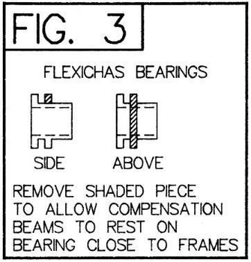
6 the gear sets back onto their axles and fit the second side plate. Centre punch the spacers to retain them, finally squeezing tight in a vice. Attach the motor to the gearbox using the old steel screws. SECTION 8: BOGIE The bogie carries the weight of the rear of the locomotive and is the third balance point of the compensation system. Bogie clearance on curves is a particularly difficult problem with this prototype. I have designed the bogie so that it is as close to the prototype as possible. Potential problem areas and possible solutions are: Top of bogie frames foul underside of main frames - file to clear. Wheels foul main frames - taper rear frames using alternative spacers Front wheels foul brake gear - use one of the alternative bogie pivots Front wheels foul tank balance pipes - File clearance on inside of balance pipes. Clearly some experimenting will be required once you have decided on the gauge being used and the desirable minimum radius of curve to be negotiated. Note that if you decide to use one of the alternative bogie pivot positions the weight of the rear of the locomotive is still carried by the bogie. This means the 10 BA screw is still used, with a nut to retain the bogie, but that the slot in the bogie stretcher will need opening out so that the bogie will pivot freely about the alternative pivot. You may also decide to dispense with the side control wires. Emboss the bogie frame rivets and form the guard irons to shape. Fold up the bogie stretcher (part 52) and solder in place in the slots in the frames. Note the slot for part 53 must be at the front. Solder the axle boxes (parts B2 & B3) in place and the wire stretchers from 0.7mm wire. Carefully ream the axle holes to 2mm diameter and temporally fit the wheels to check that the bogie is running true. Using part 18 as a guide drill two 0.7mm holes and a 1mm hole into a block of wood or Tufnol and insert 0.7mm and 1mm wire into the holes as appropriate. These pieces of wire are used as a jig to accurately align the spring components (parts 17 & 18) and the equalising beams (part 19). Note the equalising beams are asymmetric - select carefully! Fold over through 180 o the outer strips on part 17 before assembling all the components on the jig. Align carefully before soldering together. Trim the wire pins to length leaving the 1mm wire long at the back to enable the assembly to be located on the bogie through the 1mm hole in the frames. Repeat for the other side! The side control springing can now be constructed as shown in fig. 5 soldering the spring wires at one end only. If appropriate fold up part 53 and solder in place. SECTION 9: FITTING THE COMPENSATION BEAMS Cut a piece of 1/16" brass rod so that it fits through the holes C and is flush with the outside face of the chassis frames. Cut two equal pieces 3/32" tube which together fit between the frames and solder the beams (part 10) to them close to one end. Modify the Flexichas bearings as shown in Fig.3 and also remove 0.75mm from the lower edge of the bearings on the rear axle. Temporarily fit the beams. Temporarily fit all the wheels and axles and confirm that the compensation works properly and check that the chassis is sitting level. The bogie rests on a suitable selection of part 59. SECTION 10: FRAME OVERLAYS AND STEPS Emboss all the rivets on the frame overlays (parts 43, 44, 45 & 46). Fold down the sand pipe, front step and injector pipe brackets as appropriate. Those not required can be broken off. Solder in place lengths of 0.45mm wire for the brake hanger pivots. These then serve to accurately locate the overlays which only need tack soldering around their edges. Assemble the steps as shown in figs. 1 & 2. There are three positions in the frame bracket for the front step to fit. P4 inner slots - EM middle slots - OO outer slots. The front step stay must be curved so that it will pass underneath the coupling rod. 5
7 SECTION 11: FINISHING THE CHASSIS Fit the crankpins to the wheels making sure the screw heads do not foul the overlays, countersinking them if necessary. Attach the balance weights to the wheels using photographs as a guide to position. Assemble the wheel sets, bearings and rods selecting 1/8" axle washers of appropriate thickness to control sideplay. Some sideplay on the coupled wheels is desirable to assist with negotiating curves. A thorough check of all clearances at this stage is important. When you are confident of the clearances assemble the axles and quarter the wheels. You should now have a mechanically acceptable chassis. Now connect the motor to your pick-ups and test run. The axles are now retained by the springs as shown in fig. 2. Assemble the brake hangers (parts 20 & 21 or 22) before completing the brake gear as shown in Fig. 6. Complete the chassis detailing by fitting the reverse weigh shaft as shown in fig.1 and the sandboxes, sandpipes from 0.45mm wire, Duplex pumps or injectors and tank balance pipes as shown in fig. 2. SECTION 12: FOOTPLATE For a short frame locomotive shorten the footplate (part 60) by breaking off along the half-etched line. File coupling rod clearance slots in the footplate for the rear coupled axle. Make them the same as those for the front axle. Fold up the footplate valences followed by the cylinder cover sides, section of frames behind the splashers, coupling rod splasher front and the cab floor supports. Temporarily join the footplate overlay (part 61) to the footplate with a screw through the body fixing holes at the rear and aligning the sand rod pivot holes at the front. Check the alignment of the tank/bunker slots before soldering together all round. Solder a 10BA nut over the rear fixing hole. Solder the appropriate valences overlays (parts 66, 67, 68, & 69). If appropriate emboss the rivets on the bufferbeams (parts 64 & 65) and solder in place. Shorten the footplate overlay at the front for a short frame locomotive. Curve the coupling rod splasher tops (part 77) to shape by rolling underneath a suitable rod or dowel on a resilient surface (a piece of hard rubber sheet) and solder in place in the half-etched rebate along the edge of the splasher front. Insert the appropriate splasher fronts (part 72 or 75) and bend over the aligning tabs under the footplate. Similarly fit the splasher tops (parts 74 or 76) but not part 73 at this stage. Attach the sanding rods (parts 78 & &79) using 0.3mm wire as pivots. SECTION 13: SMOKEBOX AND BOILER If appropriate emboss the rivets on part 81 before folding up and soldering a 10 BA nut over the fixing hole. If appropriate emboss the rivets and drill holes for part B12 in the required smokebox front (part 83 or 84 or 85) before soldering to part 81. Modify the smokebox ballast weight (part W10) so that it will clear the frames before fixing in place. Drill any additional holes required in the smokebox wrapper (part 86 or 87) using the template in fig.8. Roll the smokebox wrapper to shape. Note part 86 is designed to be used with the etched surface inwards. Now solder the wrapper in place with the lower edges inside part 81. Drill the hole for the forward handrail knob in the boiler wrapper (part 94 or 95). It is in line with the rear hole and either 2.5mm or 9.5mm from the front edge. Roll the wrapper and check the fit on the formers (parts 31, 32 & 33). Solder the wrapper ends together using part 96 and solder in the front former. Glue the three pieces of the boiler ballast weight (part W11) together and insert in the front section of the boiler. Now solder the middle former and rear formers in place with the notch in the top of the rear former aligned with the notch in the wrapper. Represent the bolts in the joining brackets using 0.3mm wire. Solder two short lengths of 0.45mm wire in place in the rear former to act as aligning dowels with the cab front. Tap the hole in part 33 10BA so that the smokebox, parts 82 & 30 and the boiler can be screwed together. SECTION 14: CAB FRONT, BACK & INTERIOR Solder part 116 in place on the cab front (part 115) and drill out the holes for part B27 if appropriate, before folding it to shape and soldering in place in the slots in the footplate. Now check the fit of the smokebox and boiler with the cab front. If all is well continue by detailing part 122 with the coal door (part 123) and handle from 0.3mm wire before folding up and soldering in place in the footplate slots. Solder the cab floor (part 125) in place and complete the cab interior detailing by adding parts 126,127,W13,B28 and, if appropriate, 128,35,36,37,38,146,B27 & 145 as 6
8 shown in fig.12. There is no need to fix part W12 in place at this stage. Form the curve along the lower edge of part 117. If appropriate make up the cab window bars and fix in place over the rear windows in part 118. Solder part 117 and 118 together before fixing in place in the footplate slots ensuring the cab rear is upright. Form the tank vent pipe from 0.7mm wire and solder in place in the half-etched slot in the cab back. Before the tanks are fitted the boiler smokebox assembly must be permanently fixed in place. This is best done after as much of the detailing work on these assemblies is complete. This should include the handrail and lamp brackets. After permanently attaching the smokebox/boiler form cylinder cover (part 62 or 63) and solder in place between the frame extensions. Add parts B17, 76, B15 and parts 90 & 91 or 92 & 93. SECTION 15: TANKS AND BUNKER The tank sides and tops (parts 97 & 100) are the correct length for the 'long' tanks. For short tanks shorten the sides so that the front (part 98) fits inside the half-etched recess in the side. The top is broken off along the halfetched line. The 'long' tank front (part 99) fits with the side inside the half-etched recess in the front. If you are fitting the cladding plates (part 102) drill out all the marked holes on the tank sides with a 1/8" drill - be careful. This will enable the plates to be tack soldered in position from the inside through these holes. Drill through the marked holes in the tank front to fit part B16. Solder the cab cut-out beading (part 34 or 109) in place. A tight fit is essential or it will appear to be too long. Solder the appropriate tank front and the tank top in position on the tank side before removing the tie across the cab opening and inserting the tank/bunker side through the footplate slots and soldering in place. Add part 101 and the required tank top beading and if appropriate the vertical handrails - the footplate holes are marked underneath. If appropriate, add the tank cladding plates. Solder part 110 in place in the footplate slots. Form the flare at the top of part 111 and solder in place. Solder part 114 in place. Emboss the rivets on the coal rails (part 112 or 113) and fold over the stanchions through 180 o and solder to the back of the coal rails. Remove the top two rails if appropriate before folding the corners and soldering the stanchions in place inside the bunker. SECTION 16: CAB ROOF & FINAL DETAILING Fold up the back and front of part 130 which gives a solid base upon which to build the removable cab roof. Roll the cab roof to shape and solder in place on part 130 with equal overhang back and front. Add the angle pieces (parts 131,132 & 133). Now using a Carborundum disc in a mini-drill cut through the unwanted part of the former and snap off the redundant parts along the half-etched lines. The edges of the formers will now need cleaning up. Attach all the remaining components using the drawings and photographs as a guide to position. The water fillers (part B18) will need a flat filing on one side (not the lids) so that they fit inside the tank side. They must also be fitted before the main handrail. Remove 1mm from the lower edge of the back plate casting (part W12). Using the drawing of the cab interior (Fig. 16) the back plate can be assembled and the cab interior detailed. The blower valve handwheel is not shown on the drawing. It fits on the left side main handrail extended into the cab. That's it! If you have any problem with the kit or any criticisms or suggestions please feel free to contact Brassmasters. My sincere thanks to Bob Paine, Chairman of the Drummond Locomotive Society, for loaning me many valuable drawings and to all the staff at the Swanage Railway for their kind welcome and encouragement. Best wishes Martin Finney 7
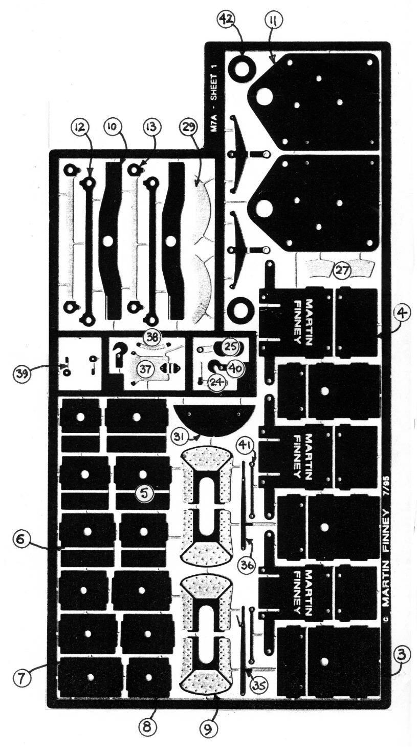
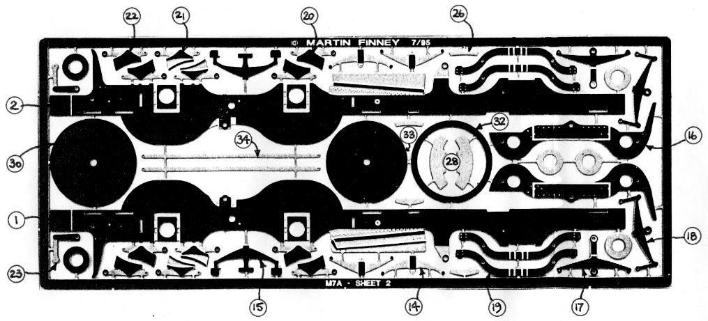
9 ETCHED COMPONENTS 1. Frame - left 45. Rear frame overlay - left 2. Frame - right 46. Rear frame overlay - right 3. Frame spacer - front 47. Rear step 4. Frame spacer - middle 48. Rear step tread - lower - (2) 5. Frame spacer - rear - parallel frames 49. Front step - (2) 6. Frame spacer - rear - tapered frames 50. Front step tread - lower - (2) 7. Frame spacer - bogie pivot - parallel frames 51. Front/rear step tread - upper - (4) 8. Frame spacer - bogie pivot - tapered frames 52. Bogie stretcher - three widths 9. Hornblock - (4) 53. Bogie pivot bracket 10. Compensation beam - (2) 54. Brake pull rod - front - (2) 11. Portescap gearbox side - (2) 55. Brake cross shaft 12. Coupling rod - inner lamination - (2) 56. Brake pull rod/lever - rear 13. Coupling rod - outer lamination - (2) 57. Washer - coupled wheel axle 14. Front spring - outer lamination - (4) 58. Washer - bogie wheel axle 15. Front spring - middle lamination - (2) 59. Washer - bogie pivot 16. Bogie frame - (2) 60. Footplate 17. Bogie spring - outer lamination - (4) 61. Footplate overlay 18. Bogie spring - middle lamination - (2) 62. Footplate overlay/cylinder cover - short frame 19. Bogie equalising beam - (4) 63. Footplate overlay/cylinder cover - long frame 20. Brake hanger/shoe - inner lamination - (4) 64. Front buffer beam 21. Brake hanger/shoe - outer lamination - early type - (4) 65. Rear buffer beam 22. Brake hanger/shoe - outer lamination - later type - (4) 66. Valence overlay - short frame - (2) 23. Lifting arm / lifting link - (2) 67. Valence overlay - long frame - (2) 24. Reversing arm / reversing rod 68. Valence overlay - right with brackets - short frame 25. Reversing shaft balance arm & weight 69. Valence overlay - right with brackets - long frame 26. Balance weight - leading axle - (4) 70. Screw coupling hook - (2) 27. Balance weight - crank axle - early - (2) 71. Screw coupling - four pieces - (2) 28. Balance weight - crank axle - alternative - (2) 72. Combined splasher front - (2) 29. Balance weight - crank axle - later - (2) 73. Combined splasher top - front section - (2) 30. Smokebox / Boiler ring 74. Combined splasher top - curved section - (2) 31. Boiler rear former 75. Separate splasher front - (2) 32. Boiler middle former 76. Separate splasher top - (2) 33. Boiler front former 77. Coupling rod splasher top - (2) 34. Cab cut out beading - (2) 78. Sanding rod - left 35. Reversing lever - lever reverse - with ratchet release 79. Sanding rod - right 36. Reversing lever - lever reverse - without ratchet 80. Steam pipe valve handle - (2) release 37. Reversing lever - lever reverse - mounting plate 81. Smokebox base/sides/back 38. Reversing lever - lever reverse - quadrant plate 82. Smokebox rear plate 39. Brake handle 83. Smokebox front - sandboxes combined with splashers 40. Coupling hook - (2) 84. Smokebox front - wing plates - sandboxes in smokebox 41. Coupling link - (2) 85. Smokebox front - wing plates removed 42. Washer - coupled wheels axle 86. Smokebox wrapper - no rivets 43. Main frame overlay - left 87. Smokebox wrapper - rivetted 44. Main frame overlay - right 88. Smokebox sandpipe flange 8
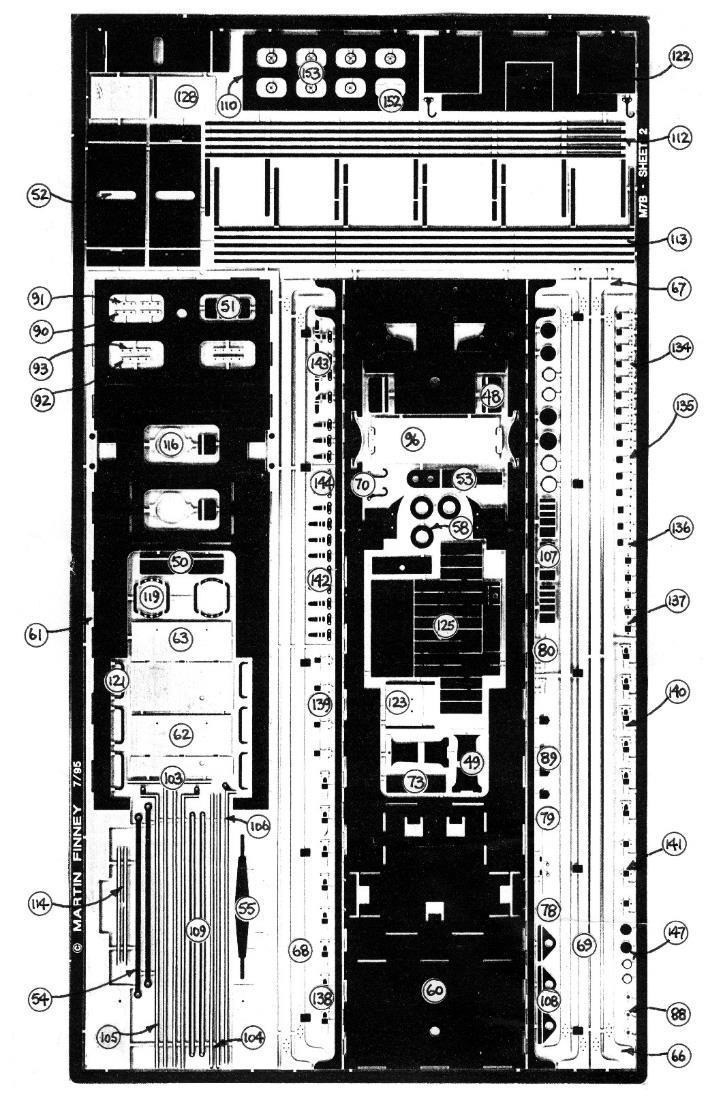
10 ETCHED COMPONENTS (continued) 89. Smokebox sandbox filler 122. Cab rear - lower 90. Wing plate/footplate angle - vertical - separate 123. Coal door sandboxes - (2) 91. Wing plate/footplate angle - horizontal - separate 124. Coal shovelling plate side quadrant sandboxes - (2) 92. Wing plate/footplate angle - vertical - combined 125. Cab floor sandboxes - (2) 93. Wing plate/footplate angle - horizontal - combined 126. Cab seat top - front - (2) sandboxes - (2) 94. Boiler wrapper - no bands 127. Cab seat top - rear - (2) 95. Boiler wrapper - with bands 128. Cab door - (2) 96. Boiler joining strip 129. Cab roof 97. Tank/bunker side - (2) 130. Cab roof building jig 98. Tank front - no feed water heating - (2) 131. Cab roof - front/rear angle - (2) 99. Tank front - feed water heating - (2) 132. Cab roof - side angle - (2) 100. Tank top - (2) 133. Cab roof - centre angle 101. Tank top rear angle - (2) 134. Lamp bracket - LSWR - footplate - (6) 102. Tank cladding - feed water heating - (2) 135. Lamp bracket - LSWR - smokebox side - (2) 103. Tank top beading - feed water heating - (2) 136. Lamp bracket - LSWR - smokebox top 104. Tank top beading - no feed water heating - (2) 137. Lamp bracket - LSWR - bunker rear - (3) 105. Tank top beading - with front hand rails - (2) 138. Lamp bracket - LSWR/SR - footplate - (6) 106. Tank top beading - RHS - repositioned front hand rail 139. Lamp bracket - LSWR/SR - smokebox side - (2) 107. Tank/boiler bracket - (2) 140. Lamp bracket - LSWR/SR - smokebox top 108. Tank lifting bracket - (2) 141. Lamp bracket - LSWR/SR - bunker rear - (3) 109. Cab cutout beading - (2) 142. Lamp bracket - SR - footplate - (6) 110. Bunker back 143. Lamp bracket - SR - smokebox side - (2) 111. Bunker back overlay 144. Lamp bracket - SR - smokebox top/bunker rear - (4) 112. Coal rails 145. Reversing lever - steam reverse - indicator 113. Coal rails - sheeted in 146. Reversing lever - lever reverse - ratchet release 114. Bunker side beading - (2) 147. Cab pressure gauges - (3) 115. Cab front 148. Fire hole 116. Cab spectacle window frame - (2) 149. Fire hole door handle 117. Cab rear - inner overlay 150. Fire hole door handle ratchet 118. Cab rear - outer overlay 151. Fire hole door flap 119. Cab window bars - frame & outer bars - (2) 152. Ejector handle 120. Cab window bars - centre bar - (2) 153. Handwheel - (3) 121. Cab window bars - intermediate bar - (4) 9
11 BRASS CASTINGS WHITEMETAL CASTINGS B1. Rear axle springs - (2) W1. Rear sandbox - left B2. Bogie axle box - left - (2) W2. Rear sandbox - right B3. Bogie axle box - right - (2) W3. Front sandbox - left B4. Injector - (2) W4. Front sandbox - right B5. Duplex pump - left W5. Tank balance pipe - (2) B6. Duplex pump - right W6. Chimney - short frame B7. Safety valve - (2) W7. Chimney - long frame B8. Injector valve - (2) W8. Dome B9. Whistle W9. Smokebox door B10. Clack box - (2) W10. Smokebox ballast weight B11. Smokebox door handles W11. Boiler ballast weight B12. Smokebox door dog - (4) W12. Backplate B13. Feed water heating pipe - (2) W13. Brake column B14. Blower valve B15. Sandbox lid - (2) OTHER COMPONENTS FOR CHASSIS B16. Lubricator - tank front - (2) 1/8" Flexichas bearing - (4) B17. Cylinder cover knob - (2) 10 BA screw - (4) B18. Water filler - (2) 10 BA nut - (3) B19. Vacuum pipe - front Brass wire - 1/16" - for compensation beam pivots B20. Vacuum pipe - rear Brass tube - 3/32" outside diameter - for compensation beams B21. Steam heating pipe - (2) Brass wire mm - for brake hanger pivots, sand pipes & step stays B22. Water gauge - (2) Brass wire - 0.7mm - for bogie and front brake cross shaft B23. Ejector/brake Brass wire - 1.0mm - for reverse weigh shaft and bogie pin B24. Regulator handle - original Brass wire - 1.2mm - for rear brake cross shaft and bogie pivot B25. Regulator handle - later Spring wire - 0.3mm - for bogie side control B26. Steam heating valve B27. Reversing lever - steam reverse B28. Brake column handle OTHER COMPONENTS FOR BODY Brass wire - 0.3mm - for injector/whistle valves & sand rod pivots Brass wire mm - for handrails Brass wire - 0.7mm - for tank vent Copper wire - 0.6mm - for pipe work Copper wire - 0.8mm - for pipe from vacuum ejector Handrail knob - short - (3) Handrail knob - medium - (4) Buffer housing, head and spring - (4) Components not provided Driving wheels: 5' 6" dia. 18 spokes Bogie wheels: 3' 7" dia. 10 spokes Pickups Motor - Portescap RG4C recommended (1616 motor) or High Level/Mashima equivalent 10
12 11

13 12

14 13
15 14
16 15
17 16
18 17
19 18
20 19
21 20
22 21
Finney7 BEYER PEACOCK BUILT LOCOMOTIVE
 BEYER PEACOCK BUILT LOCOMOTIVE Fig 1. Beyer, Peacock Built Locomotive Nos. 415-426 Depicted as built with short tanks, blower valve on the left, small dome, low tank front, 3 0 trailing wheels, snap head
FINNEY7. 24 Jul 18 A3-4 LNER A3. Fig 1. General Arrangement
 Fig 1. General Arrangement - 4 COUPLING RODS. The coupling rods are now made so that they can be used as a jig to align the hornguides accurately. First drill out all the crankpin holes to a convenient
Finney7 PC May17 PRINCESS CORONATION. Fig 1. GA Curved Footplate
 Fig 1. GA Curved Footplate PC - 5 Fig 2. GA Utility Footplate PC - 6 COUPLING RODS & FRAME ASSEMBLY COUPLING RODS. The coupling rods are now made so that they can be used as a jig to align the remaining
FINNEY7. 24 Jul 18 4 LNER A4. Fig 1. A4 GA Drawing
 Fig 1. A4 GA Drawing 24 Jul 18 4 COUPLING RODS & FRAME PREPARATION Coupling rods. The coupling rods are made so that they can be used as a jig to align the horn blocks accurately. First drill out all the
ALAN GIBSON, THE BUNGALOW CHURCH ROAD, LINGWOOD, NORWICH, NORFOLK. MIDLAND/L.M.S. Class 4F.
 ALAN GIBSON, THE BUNGALOW CHURCH ROAD, LINGWOOD, NORWICH, NORFOLK MIDLAND/L.M.S. Class 4F. These instructions and history should be carefully studied BEFORE starting on any assembly. The standard kit is
- 0 Gauge - Southern Railway Class 02 Chassis Construction & Parts Identification
 - 0 Gauge - Southern Railway Class 02 Chassis Construction & Parts Identification I would recommend constructing the body to the fitting of parts 42 before starting chassis construction. As the basic body
RT Models. 4mm scale, 00/EM/P4 Manning Wardle, class K 0-6-0ST loco kit
 1 RT Models 4mm scale, 00/EM/P4 Manning Wardle, class K 0-6-0ST loco kit History The first of Manning Wardle s Class K was built in 1864. Many of these locos were mainly built for contractors with only
BRL CLASS 66 LOCOMOTIVE. Building Instructions
 Tel 07807225801 prmrp@fsmail.net www.prmrp.com BRL - 066 CLASS 66 LOCOMOTIVE Building Instructions SCALE MODEL PRODUCT FOR ADULT MODELLERS ONLY. WHITE METAL CONTAINS LEAD WASH HANDS AFTER USE. MAY CONTAIN
Dinorwic Quarry Hunslet `Alice Class with cab 7mm Scale kit for 16.5mm or 14mm Gauge
 EDM Models 19 Briar Avenue, Acomb, York. Y026 5BX Dinorwic Quarry Hunslet `Alice Class with cab 7mm Scale kit for 16.5mm or 14mm Gauge Introduction This kit, which has been researched by Jonathan Matthews
MANNING WARDLE ex-penrhyn Quarry Railway Narrow Gauge `Jubilee mm Scale kit for 16.5mm or 14mm Gauge
 EDM Models 19 Briar Avenue, Acomb, York. Y026 5BX MANNING WARDLE ex-penrhyn Quarry Railway Narrow Gauge 0-4-0 `Jubilee 1897 7mm Scale kit for 16.5mm or 14mm Gauge Introduction This kit, which was researched
Brassmasters Scale Models
 Brassmasters Scale Models www.brassmasters.co.uk Cleminson 6-wheel underframe kit PO Box 1137 Sutton Coldfield B76 1FU Copyright Brassmasters 2016 1 Introduction 1.1 The purpose of this booklet is to guide
The 2mm Scale Association etched replacement chassis for RTR loco bodies
 The 2mm Scale Association etched replacement chassis for RTR loco bodies Required Parts List Chassis etch (supplied) Motor - for all designs the Association can motor is suitable, alternatives are shown
BRL-142/143 Class 142/143. Building Instructions
 Peter Besant Tel 07807225801 prmrp@fsmail.net www.prmrp.com BRL-142/143 Class 142/143 Building Instructions SCALE MODEL PRODUCT FOR ADULT MODELLERS ONLY. WHITE METAL CONTAINS LEAD WASH HANDS AFTER USE.
NSWGR Z Tank Locomotive
 Australian Railway Kits ABN: 27 416 246 418 Incorporating Main West Models Manufacturers, Wholesalers and Retailers of Quality Australian Model Railways PO Box 252 Warwick, Queensland, 4370 Australia Phone/Fax:
4mm scale 009 gauge Lodge Hill & Upnor railway Chattenden Drewry loco body kit.
 RT Models 4mm scale 009 gauge Lodge Hill & Upnor railway Chattenden Drewry loco body kit. HISTORY The loco was supplied by the Drewry car co. to the Lodge Hill & Upnor Railway in 1949, works number 2263.
BRL-007 Detailing and Conversion Kit for NOVO/Triang Class 35 Hymek. Building Instructions
 Peter Besant Tel 07807225801 prmrp@fsmail.net www.prmrp.com BRL-007 Detailing and Conversion Kit for NOVO/Triang Class 35 Hymek Building Instructions SCALE MODEL PRODUCT FOR ADULT MODELLERS ONLY. WHITE
Wheels, paint and transfers required to complete. Please note that to aid the folding of the various parts score all the halfetched fold lines.
 Furness Railway Wagon Co. Furness Railway/LMS 45ton All Steel Bogie Iron Ore Hopper Wagon Built by The Pressed Steel Car Co. Pittsburgh, Pennsylvania, USA Circ. 1899 Wheels, paint and transfers required
MKD 08 BR 21.5 TON FLYASH HOPPER. Wagon Kit To cover Vacuum (CSV) and air braked types (CSA)
 and air braked types (CSA)") 1 MKD 08 BR 21.5 TON FLYASH HOPPER. Wagon Kit To cover Vacuum (CSV) and air braked types (CSA) History. Pulverised fuel ash (PFA), know as fly ash which is a by-product from the combustion process in coal
1 MKD 08 BR 21.5 TON FLYASH HOPPER. Wagon Kit To cover Vacuum (CSV) and air braked types (CSA) History. Pulverised fuel ash (PFA), know as fly ash which is a by-product from the combustion process in coal
Welcome Wagons WW ton Mineral (2 & 4 shoe brake)
") Welcome Wagons WW13 16 ton Mineral (2 & 4 shoe brake) HISTORY The 16T open mineral wagon was the most numerous type built by BR from 1950 to 1957, the first diagram being 108, although there was 16T steel
Welcome Wagons WW13 16 ton Mineral (2 & 4 shoe brake) HISTORY The 16T open mineral wagon was the most numerous type built by BR from 1950 to 1957, the first diagram being 108, although there was 16T steel
Furness Railway Wagon Co.
 Furness Railway Wagon Co. Great Eastern Railway/LNER/BR 1900 Diagram 7 10ton Cattle Van Steel Under-Frame Wheels, paint and transfers required to complete. Please note that to aid the folding of the various
(WW03f) BR PIPE WAGON 4 shoe brake
 BR PIPE WAGON 4 shoe brake") (WW03f) BR PIPE WAGON 4 shoe brake History. The pipe wagons were built to four basic diagrams sharing the same basic dimensions. The first 300 pipe wagons were built at Derby works to diagram 460, and
(WW03f) BR PIPE WAGON 4 shoe brake History. The pipe wagons were built to four basic diagrams sharing the same basic dimensions. The first 300 pipe wagons were built at Derby works to diagram 460, and
Furness Railway Wagon Co. Glasgow & South Western Railway/LMS/BR 12ton Mineral Steel Under-Frame
 Furness Railway Wagon Co. Glasgow & South Western Railway/LMS/BR 12ton Mineral Steel Under-Frame Wheels, paint and transfers required to complete. Please note that to aid the folding of the various parts
Furness Railway Wagon Co.
 Furness Railway Wagon Co. The Parts. S&DJR/LMS/BR 20ton 6-Wheel Brake van Wheels, paint and transfers required to complete. Parts 13/15 Bolts/nuts/ washers Part 22 Part 5 Parts 10/19/20/21/ 23/24/25 Part
Locomotive parts April 2018
 Locomotive parts April 2018 CONTENTS Page GNR Detail parts 3 LBSC Detail parts 4 GWR Detail parts 5 LMS Detail parts 10 LNER Detail parts 13 GER Details Parts 13 BR castings 14 Tooling & spares 15 2 GNR
NSWGR C30T LOCOMOTIVE AND TENDER KIT
 Australian Railway Kits ABN: 27 416 246 418 Incorporating Main West Models Manufacturers, Wholesalers and Retailers of Quality Australian Model Railways PO Box 252 Warwick, Queensland, 4370 Australia Phone/Fax:
Heljan EM Finescale Conversion.
 Heljan 02 2-8-0 EM Finescale Conversion. Before you start, it is a good idea to have some small containers or snap top poly bags to put screws and components in for safe keeping...much better than crawling
1. Invert the tender, and hold in a suitable device. We use a foam cradle the Peco loco service cradle being ideal.
 Bachmann J11 EM Finescale Conversion Before you start, it is a good idea to have some small containers or snap top poly bags to put screws and components in for safe keeping...much better than crawling
Mamod SL1K Locomotive Assembly Instructions
 Mamod SL1K Locomotive Assembly Instructions LOCOMOTIVE ASSEMBLY INSTRUCTIONS To ensure ease of construction reference to these instructions are essential. All the major parts are in the front of the box
Bowaters cab. Rear half of tropical cab frame. Cab door 82. Bend tags and solder to cab rear in open or closed position.
 Bowaters cab 29 32 44 31 Rear half of tropical cab frame 22 27 Cab door 82. Bend tags and solder to cab rear in open or closed position. 20 21 33 Side rod fitting and valve gear - Stephensons 44 0.7mm
Bachmann GWR Earl (Dukedog) EM Finescale Conversion
 EM Finescale Conversion") Bachmann GWR Earl (Dukedog) EM Finescale Conversion Before you start, it is a good idea to have some small containers or snap top poly bags to put screws and components in for safe keeping...much better
Bachmann GWR Earl (Dukedog) EM Finescale Conversion Before you start, it is a good idea to have some small containers or snap top poly bags to put screws and components in for safe keeping...much better
Chopper Couplings. Assembly. Fitting
 Chopper Couplings Unlike most model chopper couplings, these will work with two opposing hooks, which looks so much better and allows you to turn stock at will. They are still compatible with most other
PYRTE. Building The Front Axle, Fork and Steering
 PYRTE Building The Front Axle, Fork and Steering The front axle on this traction engine is a very simple affair, in that it is a rectangular steel rod, sat on edge, with a pivot in the centre, which is
WW03e Welcome Wagons 8 Shoe Brake Pipe Wagon
 WW03e Welcome Wagons 8 Shoe Brake Pipe Wagon History The pipe wagons were built to four basic diagrams sharing the same basic dimensions. The first 300 pipe wagons were built at Derby works to diagram
Hornby Railroad Crosti 9F EM Finescale Conversion.
 Hornby Railroad Crosti 9F EM Finescale Conversion. Before you start, it is a good idea to have some small containers or snap top poly bags to put screws and components in for safe keeping...much better
Instructions for Assembling Driving Wheels, Axles and Crankpins
 Instructions for Assembling Driving Wheels, Axles and Crankpins (Version 1; October 2008) Introduction These instructions explain how to assemble Exactoscale 4mm scale driving wheels, axles and crankpins
NSWGR C LOCOMOTIVE AND TENDER KIT
 Australian Railway Kits ABN: 27 416 246 418 Incorporating Main West Models Manufacturers, Wholesalers and Retailers of Quality Australian Model Railways PO Box 252 Warwick, Queensland, 4370 Australia Phone/Fax:
Caley Coaches True Line kits in etched brass
 Caley Coaches True Line kits in etched brass 0141-772 37 Jim Smellie, 1 Tay Crescent, Bishopbriggs, Glasgow, G64 1EU. Jim Smellie Nov. 1992 10' Building Instructions for kit CC20 Caledonian Railway 1 Ton
Furness Railway Wagon Co. NBR/LNER 8ton 3PLK General Merchandise Wagon
 Furness Railway Wagon Co. General Merchandise Wagon Wheels, paint and transfers required to complete. Please note that to aid the folding of the various parts score all the halfetched foldlines that are
Furness Railway Wagon Co. NER/LNER/BR C1 5ton Fitted Open Fish
 Furness Railway Wagon Co. NER/LNER/BR C1 5ton Fitted Open Fish Wheels, paint and transfers required to complete. Please note that to aid the folding of the various parts score all the halfetched foldlines
Stephenson's Valve Gear: 7mm cast white-metal kit 19 th Century swing-link version - non-working, cosmetic only. Instructions
 SER-Kits Stephenson's Valve Gear: 7mm cast white-metal kit 19 th Century swing-link version - non-working, cosmetic only Page 1 of 5 Instructions HEALTH & SAFETY: The castings contain some lead. Dispose
Bachmann D11 EM/S4 Finescale Conversion
 Bachmann D11 EM/S4 Finescale Conversion Before you start, it is a good idea to have some small containers or snap top poly bags to put screws and components in for safe keeping...much better than crawling
Furness Railway Wagon Co.
 Furness Railway Wagon Co. The Parts. SE&CR/LB&SCR/W^D/GNR/SR/LNER/BR 1909 RCH 12ton 7 Plank Coal Wagon Wheels, paint and transfers required to complete. Part 1 Part 2 Part 9 Part 5 Part 12 Part 10 Part
Victorian Railways X Class Locomotive and tender kit
 Victorian Railways X Class 2-8-2 Locomotive and tender kit Ref.E226A&B and E227, Manufactured by DJH exclusively for Steam Era Models Introduction The first X class Heavy Mikado, number 27, entered traffic
Furness Railway Wagon Co. Great Eastern Railway/LNER/BR Diagram 18 10ton 3 Plank General Merchandise Wagon Steel Under-Frame
 Furness Railway Wagon Co. Great Eastern Railway/LNER/BR Diagram 18 10ton 3 Plank General Merchandise Wagon Steel Under-Frame Wheels, paint and transfers required to complete. The Parts. Part 1 Part 5 Part
Brake Blocks Product Code BB_7. Brake Blocks Product Code BB_7. A product from: A product from:
 Brake Blocks Product Code BB_7 The brake block types provided by these etchings are: Early sin gle sided brakes (three 4 shoe Early ei ther sided brakes ( one 4 shoe set) Later ei ther sided brakes ( three
Hornby GWR Star Class EM Finescale Conversion.
 Hornby GWR Star Class EM Finescale Conversion. Before you start, it is a good idea to have some small containers or snap top poly bags to put screws and components in for safe keeping...much better than
Norden. A Lancashire Mill Engine. Scale: 1:12
 Scale: 1:12 Neil M. Wyatt February 2009 Fig. 1: General Arrangement General Arrangement Sheet: 1 An Old Steam Engine DEAR SIR, In the ruins of an old mill at, near Rochdale, there is an old steam engine
Class BR Class 03/04 Shunter. Foldup
 Crank overlays The 2mm Scale Association BR Class 03/04 Shunter Bachmann replacement chassis Inside frames gearbox 3-680 Class 03 Class 04 coupling rods Bachmann etched replacement 03/04 chassis etch 30:1
Bachmann 1F (Half Cab) EM Finescale Conversion
 EM Finescale Conversion") Bachmann 1F (Half Cab) EM Finescale Conversion Before you start, it is a good idea to have some small containers or snap top poly bags to put screws and components in for safe keeping...much better than
Bachmann 1F (Half Cab) EM Finescale Conversion Before you start, it is a good idea to have some small containers or snap top poly bags to put screws and components in for safe keeping...much better than
Furness Railway Wagon Co. NER/LNER/BR Cattle Van
 NER/LNER/BR Medium Cattle Van Wheels, paint and transfers required to complete. Part 1 The Parts. Part 4 Part 3 Part 2 Part 17 Part 5 Part 12/16 Part 11 Part 13/14/15 Part 6/7 Parts 8/9/10 not shown Assembly
9 Locomotive Compensation
 Part 3 Section 9 Locomotive Compensation August 2008 9 Locomotive Compensation Introduction Traditionally, model locomotives have been built with a rigid chassis. Some builders looking for more realism
British Railways Standard Locomotives Microfilm Lists. British Railways Standard Locomotives Derby Microfilm List
 British Railways Standard Locomotives Microfilm Lists British Railways Standard Locomotives Derby Microfilm List Drawings 26047 to 26073 have had their original Timken drawing number added to the description.
Build your own THUNDERBIRD 2
 PACK 03 PAGE 12 Pod 3 front hatch and Elevator Car 2 43 13 Pod 3 rear hatch and Elevator Car 2 46 14 Pod 3 floor and Elevator Car 2 49 15 Pod 3 frames and FAB 1 52 16 Pod 3 frames and FAB 1 55 17 Pod 3
INSTRUCTIONS FOR NYC K-11 PACIFIC KIT #100200
 INSTRUCTIONS FOR NYC K-11 PACIFIC 4-6-2 KIT #100200 These instructions provide photographs of completed model, exploded-view drawings, diagrams, step-by-step instructions and an itemized parts list. If
Furness Railway Wagon Co.
 Furness Railway Wagon Co. The Parts. S&DJR/LMS/BR 10ton 4-Wheel Brake van Wheels, paint and transfers required to complete. Part 3 Part 2a Part 2b Part 5 Parts 8/9/10 Part 15 Part 15 Part 6 Part 4 Part
Furness Railway Coach Co.
 Furness Railway Coach Co. Outside Framed Coaches Paint and transfers required to complete. Part 32 Part 7/8 Part 9 Part 6 Part 31 Part 14 The Parts. Part 19 Parts 20/21/22 Part 5 Part 4 Part 1 Part 3 Part
GWR 4 Wheel Parcel Van, Diagram W1
 GWR 4 Wheel Parcel Van, Diagram W1 From a Colin Waite bodyline kit with a scratch built underframe April 2013. While recovering from a very nasty cold and not feeling much like doing anything I was idly
Furness Railway Wagon Co. NER/LNER/BR Box Van
 Furness Railway Wagon Co. NER/LNER/BR G1 Box Van Wheels, paint and transfers required to complete. The Parts. Parts 8/9/10 12/13/15/16 Part Part 11 Part 6 Part 2 Part 3 Part 14 Part 1 Part 4 Parts 5/7
Chevrolet 3100 IFS Kit
 1947-54 Chevrolet 3100 IFS Kit Congratulations on your purchase on what we believe is the finest IFS kit available for 1947-54 Chevrolet pickups with stock frames. We have invested many hours into designing
Hornby Railroad Hall EM Finescale Conversion.
 Hornby Railroad Hall EM Finescale Conversion. The subject of this sheet is the new (2015) Hornby Railroad Hall. There are several specification and livery variants, but all have a common chassis and as
WARNING. When installed in accordance with these instructions, the front protection bar does not affect operation of the SRS airbag.
 Part Number: 343870 F/Kit 17557 Product Deluxe Combination Winch and Non Winch Bull Bar Description: Suited to Nissan XTERRA 05ON USA Only vehicle/s: WARNING REGARDING VEHICLES EQUIPPED WITH SRS AIRBAG;
Furness Railway Wagon Co. CR/HR/LMS/PO 8ton 4PLK General Merchandise Wagon
 Furness Railway Wagon Co. CR/HR/LMS/PO 8ton 4PLK General Merchandise Wagon Wheels, paint and transfers required to complete. Please note that to aid the folding of the various parts score all the halfetched
Parts Price List. B 1 LMS/BR Parallel. (Round) B 8 LSWR Round base B 2 GWR/BR Parallel B 9 Pre Grouping Round Base Parallel.
 B 8 LSWR Round base B 2 GWR/BR Parallel B 9 Pre Grouping Round Base Parallel.") Parts Price List Please note that parts that have no price against them are not yet available. Also, I will be adding to the list, and would welcome any suggestions for parts that you may think are needed.
Parts Price List Please note that parts that have no price against them are not yet available. Also, I will be adding to the list, and would welcome any suggestions for parts that you may think are needed.
FUSELAGE ASSEMBLY SECOND SECTION (of three)
") FUSELAGE ASSEMBLY SECOND SECTION (of three) 1 FRONT FLOOR ASSEMBLY The front floor assembly is fabricated from three pieces of the two ply pre-pregnated panel material supplied. The basic floor panel and
FUSELAGE ASSEMBLY SECOND SECTION (of three) 1 FRONT FLOOR ASSEMBLY The front floor assembly is fabricated from three pieces of the two ply pre-pregnated panel material supplied. The basic floor panel and
Build your own THUNDERBIRD 2
 PACK 04 PAGE 19 Pod 3 base 66 20 Pod 3 details and Firefly 69 21 Pod 3 laboratory and Firefly 72 22 Pod 3 floor details and Firefly 75 23 Pod 3 inspection walkways 78 24 Pod 3 right inner wall 81 25 Pod
Micro-Trains #1021/#1022 Low short profile coupler
 1 Micro-Trains #1021/#1022 Low short profile coupler Low short profile coupler, for locomotives and cars with limited mounting area, makes 2 pair of either (1021) Life-Like E8A Pilot or Bachmann 4-8-4
AIRCRAFT LANDING GEAR CONSTRUCTION MANUAL
 APPENDIX AI KITPLANES FOR AFRICA AIRCRAFT LANDING GEAR CONSTRUCTION MANUAL Revision: C September 2008 Page L1 of 20 NOTE: Please read the General Manual before proceeding. Please read through the entire
Build your own THUNDERBIRD 2
 PACK 06 PAGE 33 Telescopic legs C and I.R.3 112 34 Telescopic legs D and I.R.3 115 35 Leg bases and Thunderizer 118 36 Landing feet and Elevator Car 3 121 37 Leg rail-gear racks and Elevator Car 3 124
Build the. Steam Locomotive. Pack 01
 Build the Steam Locomotive Pack 01 Build the Steam Locomotive Contents Step by step Stage 01: The smokebox door Stage 02: The smokebox Stage 03: The first driving wheels and coupling rods Stage 04: The
Section 13. Tail Rotor Drive. RotorWay International A600 TALON Construction Manual. Section 13. Page A
 RotorWay International Page A Tail Rotor Drive Procedures covered in this section: Install driveshafts and gearboxes; install drive belt and tensioner; fabricate and install tail rotor pitch actuator arms;
Jabiru J170/230/430/250/450 Constructors Manual. Pre-Paint>Fuselage>Undercarriage>Assemble main gear
 Objectives of this task: In this task you will assemble the main undercarriage legs, which includes fitting the axles, disc brakes and wheels and adjusting the brakes. Materials required: Cards # J8 Dual
COLD AIR INTAKE INSTALLATION INSTRUCTIONS
 COLD AIR INTAKE INSTALLATION INSTRUCTIONS # D760-0033 Fits: 2013-15 F01 B7, 750i & xdrive (N63TU engine) 2013-15 F02 B7L, 750Li & xdrive (N63TU engine) PARTS LIST Left and right carbon fiber air box lids
Thank you for purchasing the Blackstone Models K-27!
 Operations Manual Thank you for purchasing the Blackstone Models K-27! Before your Mudhen whistles off, we want to tell you about a few things that will enhance your operating experience and ensure that
KITS AND FITTINGS CATALOGUE AND PRICE LIST
 Brassmasters Scale Models PO Box 1137 Sutton Coldfield West Midlands B76 1FU www.brassmasters.co.uk 4mm SCALE KITS AND FITTINGS CATALOGUE AND PRICE LIST 1 November 2012 email : sales@brassmasters.co.uk
Build your own THUNDERBIRD 2
 PACK 01 STAGE PAGE 01 Nose assembly and Elevator Car rear wheels 3 02 Cockpit interior and Elevator Car 1 completion 7 03 Missile launcher and Thunderbird 4 11 04 Nose assembly and the Tracy brothers 15
INSTALLATION GUIDE PREMIUM FRONT BUMPER FOR RAM AEV30304AA Last Updated: 09/18/17
 AEV30304AA Last Updated: 09/18/17 PREMIUM FRONT BUMPER FOR RAM 1500 INSTALLATION GUIDE PLEASE READ BEFORE YOU START To guarantee a quality installation, we recommend reading these instructions thoroughly
Building a 3-D Printed Coach by Al Mueller
 Gerry Dykstra has created an antebellum/civil War era coach on the Shapeways web site. Gerry used Inventor software to design the car. His finished product, in my opinion, is a much more accurate rendition
In area - A -, a proper seal must be made against the top of the window glass.
 Door window, adjusting Page 1 of 3 Audi > B3 > 1994-1998 Body Exterior, Interior 61 - Convertible top, checking and adjusting Door window, adjusting Sections C-C and D-D. Adjust door window so that window
Times-2 Speed Files INSTALLATION INSTRUCTIONS
 Times-2 Speed Files INSTALLATION INSTRUCTIONS AURORA from RICHARDS-WILCOX, INC. 600 South Lake Street Aurora, Illinois 60506 Phone: 630-897-6951 Fax: 630-897-6994 Toll Free: 800-277-1699 TIMES-2 SPEED
JDWDS. No: DHR-B-45-01
 .0.0.0... NOTE: THE ORIGINAL DESIGN OF THIS MODEL ENGINE WAS MADE BY Mr. H.E.SCHEELE, AND PUBLISHED IN THE DUTCH MAGAZINE "ONDER STOOM", MAGAZINE NUMBERS TO GENERAL ARRANGEMENT E-MAIL: dewaal@xtra.co.nz.
JK REAR BUMPER AND TIRE CARRIER
 JK REAR BUMPER AND TIRE CARRIER Installation Guide AEV30105AA (Updated 5/10/10) Page 1 of 20 Page 2 of 20 EXPLODED VIEW PLEASE READ BEFORE YOU START IN ORDER TO INSTALL THIS PART PROPERLY YOU OR YOUR INSTALLER
WARNING TAKE NOTE OF THE FOLLOWING: THIS PRODUCT MUST BE INSTALLED EXACTLY AS PER THESE INSTRUCTIONS USING ONLY THE HARDWARE SUPPLIED.
 ARB WINCH/NONWINCH BUMPER TO SUIT TOYOTA HJ100 IFS PRODUCT No. 3913140 5100050 Top Tube Kit 5100160 Buffer Kit With hole (required when fitting Top Tube) 5100170 Buffer Kit With no hole Fitting Kit No.
SS41HF Mitsubishi Pajero NS & NT V8/V9 Series 3.2 Litre Turbo Diesel (4M41 Engine) 3.8 Litre V6 Petrol (6G76 Engine)
 3.8 Litre V6 Petrol (6G76 Engine)") SS41HF Mitsubishi Pajero NS & NT V8/V9 Series 3.2 Litre Turbo Diesel (4M41 Engine) 3.8 Litre V6 Petrol (6G76 Engine) 21/7/2010 Parts List ITEM PART NO DESCRIPTION QTY 1 570-133-200 BODY - SNORKEL (SS41HF)
SS41HF Mitsubishi Pajero NS & NT V8/V9 Series 3.2 Litre Turbo Diesel (4M41 Engine) 3.8 Litre V6 Petrol (6G76 Engine) 21/7/2010 Parts List ITEM PART NO DESCRIPTION QTY 1 570-133-200 BODY - SNORKEL (SS41HF)
INSTALLATION GUIDE. JK Rear bumper & tire carrier. AEV30105AC Last Updated: 10/11/16 US PATENT: D642,502 ; D
 AEV30105AC Last Updated: 10/11/16 JK Rear bumper & tire carrier US PATENT: D642,502 ; D633.024 INSTALLATION GUIDE PLEASE READ BEFORE YOU START TO GUARANTEE A QUALITY INSTALLATION, WE RECOMMEND READING
7mm Axleguards AX1_7 RCH/MR Standard Axleguards
 AX1_7 RCH/MR Standard Axleguards Exhibitions, or through selected retailers. GX1_7 GWR Standard 4 bolt Axleguards Exhibitions, or through selected retailers. AX2/7 Pre Group General Axleguards (Includes
Furness Railway Wagon Co.
 Furness Railway Wagon Co. S&DJR/LSWR/Midland Railway/LMS/SR/BR 1898/1904 8ton 2 Plank Wagon Wheels, paint and transfers required to complete. The Parts. Part 1 Part 4 Part 5 Part 10 Parts 7/8/9 Parts 13/14
Fuel Tank Fitment Instructions Tusk/Rally Raid Products/Seat Concepts kit Husqvarna 701 Enduro
 Fuel Tank Fitment Instructions Tusk/Rally Raid Products/Seat Concepts kit Husqvarna 701 Enduro Part #1849120001, 1849120002, 1849110001, 1849110002 Thank you for purchasing the Tusk/Rally Raid Products
Plumbing Part VI - Blowdown Valve Nelson Riedel Initial: 9/28/03 Last Revised: 04/24/2006
 Page 1 of 8 Plumbing Part VI - Blowdown Valve Nelson Riedel Nelson@NelsonsLocomotive.com Initial: 9/28/03 Last Revised: 0 When I started to think about the blowdown I realized that I'd never seen the actual
KITS AND FITTINGS CATALOGUE AND PRICE LIST
 Brassmasters Scale Models PO Box 1137 Sutton Coldfield West Midlands B76 1FU www.brassmasters.co.uk 4mm SCALE KITS AND FITTINGS CATALOGUE AND PRICE LIST 1 March 2014 email : sales@brassmasters.co.uk Payment
12.0 CONTROLS 3/3/2006. Page 1
 Page 1 Page 2 SR3500 Rudder Pedal Parts List ITEM DESCRIPTION PART NUMBER QTY 1 MASTER BRAKE PEDAL RP0015 2 2 SLAVE BRAKE PEDAL RP0016 2 3 PUSH ROD RP0017 4 4 SLAVE BRAKE TORQUE TUBE RP0018 2 5 MASTER
Mounting Body CHAPTER 9
 CHAPTER 9 Mounting Body During the build of your car, you will need to trial fit the body numerous times. It is possible to construct a simple moveable rack that can lift the body and then move the body
REMOVAL & INSTALLATION
 REMOVAL & INSTALLATION Removal 1. Center steering wheel. Disconnect negative battery cable. Remove steering coupling shield (if equipped). Disconnect steering shaft at flexible coupling or pot joint. Note
Completion Of Heritage Annual Inspection Steam Locomotives
 Page 1 of 10 Completion Of Heritage Annual Inspection Steam Locomotives This cover sheet is to be completed by the inspector for each Heritage Vehicle inspected. The Heritage Vehicle Provider is to provide
Lionel Class Era Steam: 384, 385, 390, 392, 400 Classic Steam Data Collection Form. Version 1.7
 Lionel Class Era Steam: 384, 385, 390, 392, 400 Classic Steam Data Collection Form. Version 1.7 1. Reporter names Date: December 26, 2012 6 pm 2. 384, 384E, 385E, 390, 390E 392E, 400E, 1760, 1770, 1770E
COLD AIR INTAKE INSTALLATION INSTRUCTIONS. # D Fits: F10 M5 # D Fits: F06/F12/F13 M6 PARTS LIST
 COLD AIR INTAKE INSTALLATION INSTRUCTIONS # D760-0035 Fits: 2013-15 F10 M5 # D760-0037 Fits: 2012-15 F06/F12/F13 M6 PARTS LIST (1) Left Carbon Airbox Lid (1) Right Carbon Airbox Lid (1) Left Carbon Snorkel
J2 Remove sound insulation/knee guard 1 and side panel 2 on center console
 J1 Preparations Drive car forward on a level surface so that wheels are straight. Disconnect battery negative lead. Turn ignition key to position 1 so that steering lock is off. J2 Remove sound insulation/knee
SEARAILS RR-XXX STEAM LOCOMOTIVES ASSEMBLY MANUAL
 SEARAILS RR-XXX 0-4-0 STEAM LOCOMOTIVES ASSEMBLY MANUAL 30 March 2015 T R Knapp Model Engineering 1 This diagram shows basic assembly of Nn3/Z Porter 0-4-0T 2 This diagram shows basic assembly of Baldwin
Mopar 8 3/4 & 9 3/4 (Dana) Installation Instructions Rear Disc Conversion
 Installation Instructions Rear Disc Conversion") Mopar 8 3/4 & 9 3/4 (Dana) Installation Instructions Rear Disc Conversion This kit is for either Mopar 8 ¾ or Mopar 9 ¾ (Dana). This kit is designed to work with axles with either GM 5 x 4.75 Bolt Pattern
Mopar 8 3/4 & 9 3/4 (Dana) Installation Instructions Rear Disc Conversion This kit is for either Mopar 8 ¾ or Mopar 9 ¾ (Dana). This kit is designed to work with axles with either GM 5 x 4.75 Bolt Pattern
BOWSER - PARTS Air compresser mounting brkt Air compressor Back plate for LEAD Cast K Air tank.
 A 70044 Air compressor 70111 Air compressor 70192 Air compresser mounting brkt. B 15011 Bearing, driver 1/8" hole 15012 Bearing, driver, square, 1/8" hole, for.040 side rails on underframe 908 Brass bearing,
Furness Railway Wagon Co.
 Furness Railway Wagon Co. S&DJR/LSWR/Midland Railway/LMS/SR 1883 8ton 5 Plank Raised End Wagon And S&DJR/Midland Rly/LSWR/SECR/PD&SWJR/ H&BR/LMS/SR/LNER 1883 8ton 5 Plank Wagon Wheels, paint and transfers