MBW SLIPFORM PAVER PURCHASE AWARENESS
|
|
|
- Myra Black
- 5 years ago
- Views:
Transcription
1 L11547/ 7.06 E MBW inc copyright 2006
2 i
3
4 MBW SLIPFORM PAVER PURCHASE AWARENESS WHEN PURCHASING AN MBW SLIPFORM PAVER YOU MUST CONSIDER THE PURCHASE OF NOT JUST A PAVER, BUT A SLIPFORMING PROCESS. PAVER PERFORMANCE IS DEPENDANT UPON ADEQUATE CONTROL OF THE FOLLOWING VARIABLES: GRADE MUST BE ACCURATE. GRADE CAN NOT BE HIGH. GRADE CAN BE LOW, ALTHOUGH LOW GRADE WILL ADVERSELY AFFECT YIELD. MBW RECOMMENDS DRY RUNNING BLADE OFF STRINGLINE TO REFINE GRADE. MBW recommended mix is stated on page 36 of manual. 50%-50% (about #1500 (680kg) each) mixture of 3/4"(2 cm) of rock and sand 550# (250 Kg) of cement (6 bag mix) 6% AIR ENTRAPMENT ON SITE 3. SLUMP MUST BE MAINTAINED AT APPROXIMATELY 1 1/2 TO 2 1/2 (2.5-6cm). 4. STRINGLINE MUST BE PROPERLY SET. 5. THERE MUST BE A PROFICIENT PAVER OPERATOR. 6. FINISHERS MUST KNOW HOW TO FINISH A SLIPFORM PRODUCT.
5
6
7


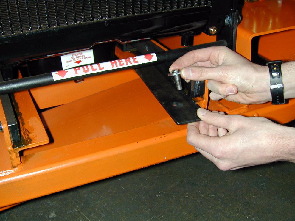
8 SAFETY DECAL LOCATIONS CAREFULLY READ AND FOLLOW ALL SAFETY WARING DECALS. REPLACE ALL DAMAGED OR MISSING SAFTEY DECALS. 1. Control Panel: 1. Control Panel Decal # (See page 13) 2. Vibrator Decal #11699, Right side of control panel. (See page 14) 2. Engine Compartment: 1. Pull Here #11413, Below radiator. 2. Fan Warning #11537, right side of rać diatior and top of radiator shroud. 3. Oil Drain #08529, Below radiator on front of oil pan 3. Main Unit, Engine Access Panel. 1. Safety Operating Instructions 2. Tie Down # Hot #09311, Above exhaust opening 6


9
10
11
12


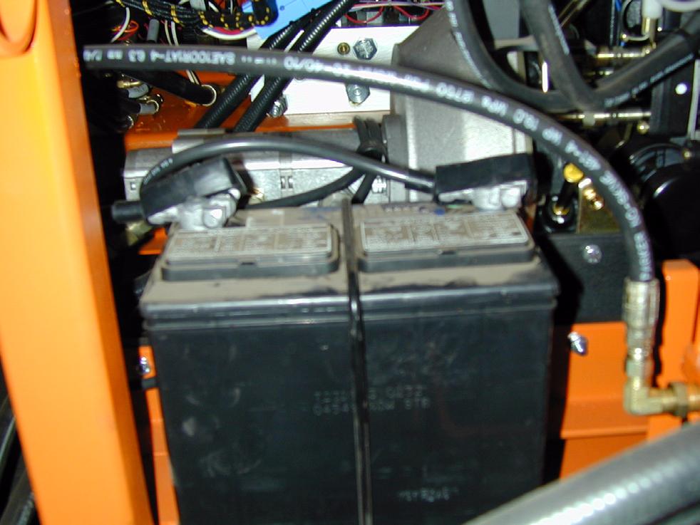
13 SERIAL NUMBERS MAIN UNIT SERIAL NUMBER Inside engine compartment towards left while facing the engine radiator SIDE UNIT UNIT SERIAL NUMBER On front face of side unit height cylinder top support ENGINE SERIAL NUMBER On engine block boss underneath air inć take manifold. - 11
14
15
16
17
18
19
20
21
22
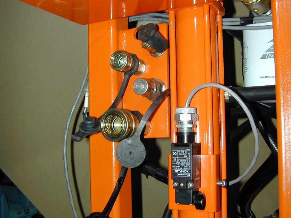
23 1 2 3 NOTE: Any vibrator parts which are not being used, the corresponding vibrator control must be switched off completely or you will dead head (a restricted flow of hydraulic fluid that will kill the engine) the hydraulic system
24
25
26
27
28
29
30
31
32
33
34
35
36
37
38
39


40


 and discard OĆring. 6. Remove fuel filter with filter wrench. 7. Screw new filter on by hand until gasć ket contacts housing.")
41 7. Wipe a film of clean oil on the new filć ter seal. 8. Tighten filter until seal contacts mounting surface. Hand tighten an additional 1/2 to 3/4 turn. 9. Replace drain plug and fill engine with oil. 10. Run engine for a few minutes and shut off. 11. Check oil level and inspect for leaks. CLEANING ENGINE AIR FILTER: 1. Remove and inspect filter. 2. Clean or replace frequently in dusty work conditions. 3. Replace filter. Ensure that all seals seat properly. CLEANING/REPLACING FUEL FILTER: 8. Install drain plug with new OĆring. 1. Stop engine. To only drain water from fuel filter: 2. Place a drain pan under fuel filter and loosen drain plug approximately 1 turn. 3. Water should drain. If necessary, opć erate priming pump to drain water, but only until fuel flows from filter. 4. Tighten drain plug. Goto step 9. To replace fuel filter: 5. Remove drain plug (on bottom of filć ter) and discard OĆring. 6. Remove fuel filter with filter wrench. 7. Screw new filter on by hand until gasć ket contacts housing. Then tighten 1/3 turn more. 9. Operate priming mechanism on top of filter. 10.Start engine. Check for leaks. Primer Filter Drain Plug 39

42

43


44
45
46
47
48
49
50 1 2 3 R L R L R L 3 LD OFF POS C C C L C R L C R TRIM POT D2 3 2 HP AP AUX P T 3 17 B F D1 2 SAM BLHT 2 1 GND D D2 3 6 RD MP 2 3 SDU VIB BAT 15 AMP TS THT SPD LIGHT CLUSTER HOUR METER + 6 IGNITION AC GLOW LAMP RHT 6 4 FNR D2 CEN D1 D D1 12 FRT STR D2 7 D2 LTS SPEED POT D1 LFT 5 STR CNTRL MOD HGT CNTRL MOD WHT 12 BLK BRN GRN BLU RED ORG YEL BRN GRN BLU ORG YEL RED WHT DBL LBL WHITE 12 GA RED 12 GA WHITE BROWN YELLOW D BLUE OFF POS RED AMP 39 BLACK LC1 LC2 LC5 LC6 BLACK BLACK BLACK BLACK GREY L BLUE ORANGE ORANGE PURPLE PINK ORANGE BAT GND 2 AUX OFF POS OFF POS VIB 3 POT VIB 2 POT VIB 1 POT YELLOW ORANGE GREY GREEN PINK PURPLE BROWN TAN D BLUE L BLUE YELLOW 3 50 BLACK 2 51 BLACK 1 52
51
52 IMPORTANT
53
54 Open mold requires open drop adapter
55
56 MBW INC. MOLD ORDER FORM MOLD PURCHASE ORDER OF THE MOLD WILL NOT BEGIN UNTIL ALL REQUIRED INFORMATION IS RECEIVED!!! THEN 10 WORKING DAYS ARE NECESSARY TO PRODUCE A MOLD. FULL PAYMENT IS REQUIRED BEFORE SHIPMENT. Size of Hopper Opening For Mold POURING CONDITIONS REBAR LOCATIONS
Boxer 322D Parts Manual
 BIG POWER IN ALL PLACES Boxer D Parts Manual Serial No.s and Higher Part No. -80 Phone: Sales - 800-8-00, Parts and Service - 800--88 www.boxerequipment.com Manufactured by: Morbark, Inc. 80 S. Winn Rd.,
INSTALLATION INSTRUCTIONS
 INSTALLATION INSTRUCTIONS Accessory Application Publications No. BII 39889 HITCH 2009 MDX Issue Date JULY 2008 PARTS LIST Trailer Hitch Kit P/N 08L92-STX-200 Trailer Harness Kit P/N 08L91-STX-200 Trailer
POWERED RUNNING BOARDS INSTALLATION MANUAL
 POWE RUNNING BOARDS INSTALLATION MANUAL Level of Difficulty Moderate Parts List 1 Driver / left running board* 1 Passenger / right running board* 4 Mounting bracket, standard 2 Mounting bracket, middle
INSTALLATION INSTRUCTIONS
 INSTALLATION INSTRUCTIONS Accessory Application Publications No. All 28632 TRAILER HITCH 2006 RIDGELINE Issue Date FEB 2005 PARTS LIST Receiver cover Trailer Hitch Kit: P/N 08L92-SJC-100 Trailer hitch
INSTALLATION INSTRUCTIONS
 INSTALLATION INSTRUCTIONS Accessory Application Publications No. AII 36765 S 2008 RIDGELINE Issue Date JUN 2007 PARTS LIST Relay Fog Light Kit P/N 08V31-SJC-100 Right fog light 15 Wire ties Left fog light
CORROSION PROTECTION ALL MODELS
 CORROSION PROTECTION 7 22032 A ALL MODELS Table of Contents Page Continuity Circuit......................... 7A-1 Anodic Block............................ 7A-3 Replacement.......................... 7A-3
This vehicle uses HFC 134a (R 134a) refrigerant, which does not contain chlorofluorocarbons. Pay attention to the following service items:
 refrigerant, which does not contain chlorofluorocarbons. Pay attention to the following service items:") HEATING AND A/C SYSTEM DESCRI... 2007 CIVIC Heating and A/C System Description The air conditioning (A/C) system removes heat from the passenger compartment by transferring heat from the ambient air to
HEATING AND A/C SYSTEM DESCRI... 2007 CIVIC Heating and A/C System Description The air conditioning (A/C) system removes heat from the passenger compartment by transferring heat from the ambient air to
WIRING DIAGRAM SYMBOLS
 WIRING DIAGRAM SYMBOLS Article Text 1989 Toyota MR2 For Ace Mechanics 123 Main Street San Diego Ca 92126 Copyright 1997 Mitchell International Friday, November 28, 2003 09:15AM ARTICLE BEGINNING WIRING
INSTALLATION INSTRUCTIONS
 INSTALLATION INSTRUCTIONS Accessory Application Publications No. AII 28603 S 2006 RIDGELINE Issue Date FEB 2005 PARTS LIST Relay Fog Light Kit P/N 08V31-SJC-100 Right fog light 15 Wire ties Left fog light
INSTALLATION INSTRUCTIONS
 INSTALLATION INSTRUCTIONS Accessory HITCH Application 2013 MDX Publications No. BII 13442 Issue Date JULY 2012 PARTS LIST Receiver cover Trailer hitch Hitch pin Left bracket Hitch pin clip Trailer Harness
21511 Commercial Light Kit Part # Qty Description
 21511 Commercial Light Kit Part # Qty Description * 1 Plug in 21563 1 Battery Cable, 90" 8324 6 Cable Ties, 3/16" x 14" 21651 3 Split Rubber Grommet 21652 3 Rosebud Clip -.413/.500 21288 1 Blade Terminal
Applicable to the Following Part Numbers. Notes and Maintenance. Torque Specifications. Metric SAE. Use above torque setting unless otherwise noted
 INSTALLATION MANUAL Level of Difficulty Moderate This is the second first of two of two manuals required to complete this installation. The first second manual manual is is included with with your mounting
INSTALLATION INSTRUCTIONS
 INSTALLATION INSTRUCTIONS Accessory Application Publications No. S P/N 08V31-SCV-102 2008 ELEMENT AII 36531 Issue Date MAY 2007 PARTS LIST 15 Wire ties 2 Fog lights 4 Wire ties with clip Switch harness
INSTALLATION INSTRUCTIONS
 INSTALLATION INSTRUCTIONS Accessory Application Publications No. All 27176-28932 2005 CR-V Issue Date S P/N 08V31-S9A-115 FEB 2005 PARTS LIST 6 Washer-bolts Left fog light 6 Spring nuts Harness bracket
Spreader and Vehicle Battery Kits
 May 5, 20 Lit. No. 922, Rev. 04 and Vehicle Battery Kits Hopper s Parts List and Installation Instructions CAUTION Read this document before installing the and Vehicle Battery Kit. CAUTION Use standard
INSTALLATION INSTRUCTIONS
 INSTALLATION INSTRUCTIONS Accessory Application Publications No. S P/N 08V31-SCV-100B 2008 ELEMENT (SC) AII 36532 Issue Date MAY 2007 PARTS LIST Relay bracket Right fog light Relay Left fog light Fuse
INSTALLATION INSTRUCTIONS
 INSTALLATION INSTRUCTIONS Accessory Application Publications No. KIT 08V31-SEC-201 2004 TSX BII 24805 Issue Date APRIL 2003 PARTS LIST 16 Wire ties Left fog light Right fog light Relay Right fog light
INSTALLATION INSTRUCTIONS
 INSTALLATION INSTRUCTIONS Accessory Application Publications No. P/N 08V31-SDA-102 2007 ACCORD 4-DOOR AII 32672 Issue Date JULY 2006 NOTE: Fog lights can be installed in a vehicle equipped with a factory
 1 of 37 2/25/18, 1:04 PM 2 of 37 2/25/18, 1:04 PM 3 of 37 2/25/18, 1:04 PM 4 of 37 2/25/18, 1:04 PM 5 of 37 2/25/18, 1:04 PM 6 of 37 2/25/18, 1:04 PM 7 of 37 2/25/18, 1:04 PM 8 of 37 2/25/18, 1:04 PM 9
POWER TRIM 5 E DUAL POWER TRIM CONTROL
 POWER TRIM 5 E 22129 DUAL POWER TRIM CONTROL Table of Contents Page Important information..................... 5E-1 Testing Dual Power Trim System........... 5E-1 Relay Test............................
8436, 8437, 8438, 8439, 8442, 27480, 27780, 28028, & ISOLATION MODULE ELECTRICAL SYSTEM
 September 11, 2003 Lit. No. 27808 8436, 8437, 8438, 8439, 8442, 27480, 27780, 28028, & 28400 ISOLATION MODULE ELECTRICAL SYSTEM Installation Instructions Read this document before installing the snowplow.
INSTALLATION INSTRUCTIONS
 INSTALLATION INSTRUCTIONS Accessory Application Publications No. P/N 08V31-SDA-102 2007 ACCORD HYBRID AII 32762 Issue Date JULY 2006 NOTE: The outside temperature gauge cannot be installed in a vehicle
INSTALLATION MANUAL. Middle. Def tank. Standard. Middle. Standard. Def tank WARNING. Level of Difficulty CAUTION. Parts List.
 INSTALLATION MANUAL 3025101 Level of Difficulty Moderate This is the second first of two of two manuals required to complete this installation. The first second manual manual is is included with with your
UNIVERSAL WIRING HARNESS Installation Manual
 UNIVERSAL WIRING HARNESS Installation Manual Terminals are provided for most connections on your wiring kit. Following the gauge manufacturer s instructions, use the terminals supplied with your gauge
INSTALLATION INSTRUCTIONS
 INSTALLATION INSTRUCTIONS Accessory Application Publications No. All 27176 2005 CR-V Issue Date P/N 08V31-S9A-114 SEP 2004 PARTS LIST 25 Wire ties Left fog light 6 Washer-bolts Right fog light 6 Spring
Classic Update Series
 *** These are special instructions for connecting your wiring system to a stock instrument cluster. *** NOT: If you are using after market gauges, follow the instructions included in the 92965220 Gauge
INSTALLATION INSTRUCTIONS
 INSTALLATION INSTRUCTIONS Accessory Application Publications No. P/N 08V31-SNA-100 2007 CIVIC HYBRID AII 33829 Issue Date SEP 2006 PARTS LIST Fog light harness Right fog light Left fog light Subharness
INSTALLATION INSTRUCTIONS
 INSTALLATION INSTRUCTIONS Accessory Application Publications No. AII 24075 2003 ACCORD P/N 08V31-SDN-100 2-DOOR Issue Date AUG 2002 NOTE: The outside temperature gauge can not be installed in a vehicle
Chevy Pickup Control Panel Kit
 an ISO 9001:2008 Registered Company 1960-63 Chevy Pickup Control Panel Kit 473262 18865 Goll St. San Antonio, TX 78266 ph: 210-654-7171 fax: 210-654-3113 903258 REV C 9/19/14, INST 60-63 CHEV P-UP CNTRL
INSTALLATION INSTRUCTIONS
 INSTALLATION INSTRUCTIONS Accessory Application Publications No. P/N 08V31-SVA-110 2007 CIVIC 2-DOOR All33536-34848 Issue Date FEB 2007 PARTS LIST 11 Wire ties Right fog light Clip Left fog light 4 Stepped
service bulletin MCM 4.3L, 4.3LX Alpha GM Generation II Engine Specifications No
 service bulletin TO: SERVICE MANAGER MECHANICS PARTS MANAGER No. 91-17 MCM 4.3L, 4.3LX Alpha GM Generation II Engine Specifications NOTE: These engines have an electric fuel pump because there is no pad
Chevy Pickup Standard Control Panel Conversion Kit
 an ISO 900: 2008 Registered Company 955-59 Chevy Pickup Standard Control Panel Conversion Kit 473258 8865 Goll St. San Antonio, TX 78266 ph: 20-654-77 fax: 20-654-33 909 REV B 9/9/4, INST 55-59 CHEVY PICKUP
INSTALLATION INSTRUCTIONS
 INSTALLATION INSTRUCTIONS Accessory Application Publications No. 2007 CIVIC 2-DOOR All33536-34068 Issue Date SEP 2006 PARTS LIST 11 Wire ties Right fog light Clip Left fog light 4 Stepped screws 2 Washer
service bulletin MCM 7.4L Bravo, MIE 7.4L Inboard GM Generation V Engine Specifications No. 91-6
 service bulletin TO: SERVICE MANAGER MECHANICS PARTS MANAGER No. 91-6 MCM 7.4L Bravo, MIE 7.4L Inboard GM Generation V Engine Specifications NOTE: Generation V Engines Have the Fuel Pump Mounted on the
INSTALLATION INSTRUCTIONS
 INSTALLATION INSTRUCTIONS Accessory Application Publications No. P/N 08V31-SVA-100 2006 CIVIC 2-DOOR All 30890 Issue Date SEP 2005 PARTS LIST 11 Wire ties Right fog light Clip Left fog light 4 Stepped
INSTALLATION INSTRUCTIONS
 INSTALLATION INSTRUCTIONS Accessory Application Publications No. All 26124 CR-V Issue Date SEP 2003 P/N 08V31-S9A-112 PARTS LIST 4 Washer-bolts, 6 x 20 mm Left fog light 2 Small spring nuts Right fog light
GEN IV ROTARY CONTROL PANEL KIT
 GEN IV ROTARY CONTROL PANEL KIT 492050 GEN IV ROTARY CONTROL PANEL KIT No QTY PART No. DESCRIPTION. 2. 3. 4. 5. 6. 7. 8. 9. 0. 3 2 3 5 490006 24608-0 8235-VUB 497004 232002-VUA 230-VUP 23520 205550 20555
service bulletin MCM 350 Magnum Alpha, MCM 5.7L Bravo, MIE 350 Magnum Tournament Ski Inboard Specifications No. 91-8
 service bulletin TO: SERVICE MANAGER MECHANICS PARTS MANAGER No. 91-8 MCM 350 Magnum Alpha, MCM 5.7L Bravo, MIE 350 Magnum Tournament Ski Inboard Specifications NOTE: These three engines have a steel camshaft
Accessory Harness & Bracket Kit
 Accessory Harness & Bracket Kit Stainless Steel Hopper Spreader Gas 9969 June 5, 06 Lit. No. 98986, Rev. 0 PARTS LIST 9 4 8 7 6 4 3 8 VIB LIGHT STROBE PREWET 5 0 4 9969 Accessory Harness & Bracket Kit
Boxer 525DX Parts Manual
 BIG POWER IN ALL PLACES Boxer DX Parts Manual SN Part No. 3-13 Phone: Sales - 00-31-00, Parts and Service - 00--3 www.boxerequipment.com Manufactured by: Morbark, Inc. 0 S. Winn Rd., P.O. Box 00, Winn,
INSTALLATION INSTRUCTIONS
 INSTALLATION INSTRUCTIONS Accessory Application Publications No. P/N 08V31-SDN-100 2004 ACCORD 2-DOOR AII 25735 Issue Date SEP 2003 NOTE: The outside temperature gauge can not be installed in a vehicle
TELORVEK EFI 5.0 Coyote Sequential Fuel Injection System Part # CY-11
 Page #1 TELORVEK EFI 5.0 Coyote Sequential Fuel Injection System Part # CY-11 WIRING INSTRUCTIONS Thank you for purchasing the absolute finest of wiring kits for the Ford Motor Co. Coyote modular engine.
service bulletin MCM 454 Magnum EFI, MIE 454 EFI Ski GM Gen V Engine Specifications No Magnum 454 EFI Model EFI Ski (Average Octane Rating)
") service bulletin TO: SERVICE MANAGER MECHANICS PARTS MANAGER No. 93-25 MCM 454 Magnum EFI, MIE 454 EFI Ski GM Gen V Engine Specifications NOTE: Generation V Engines Have the Fuel Pump Mounted on the Belt
service bulletin TO: SERVICE MANAGER MECHANICS PARTS MANAGER No. 93-25 MCM 454 Magnum EFI, MIE 454 EFI Ski GM Gen V Engine Specifications NOTE: Generation V Engines Have the Fuel Pump Mounted on the Belt
Bel Stewart Connector
 Individually Shielded Pair Cable END END With Orange on left and Brown on right, one end of cable has Green on top, other end has Blue on top. Green end steps will be shown on left, Blue steps shown on
8/6/2013 LX-30 MACHINES: COPYRIGHT 6/10/10 ALL RIGHTS RESERVED
 LX-0 MACHINES: 00 000 STONEKOR LLC -800-6-09 customerservice@stonekor.com www.stonekor.com PAGE LX-0 GRINDER DECK SUB ASSEMBLY 0 6 7 7 9 8 8 9 8 7 6 0 9 7 8 6 7 6 8 0 6 0 PAGE LX-0 GRINDER DECK SUB ASSEMBLY
Western Products, PO Box , Milwaukee, WI Hopper Spreader. Control Wiring and Electrical Components
 Western Products, PO Box 2403, Milwaukee, WI 3224-3 www.westernplows.com August 1, 201 Lit. No. 201, Rev. 0 Hopper Spreader Control Wiring and Electrical Components Installation Instructions and Parts
INSTALLATION INSTRUCTIONS
 INSTALLATION INSTRUCTIONS Accessory Application Publications No. ACCORD AII 24050 4-DOOR P/N 08V31-SDA-100 Issue Date AUG 2002 NOTE: The outside temperature gauge cannot be installed in a vehicle with
 INSTALLATION INSTRUCTIONS Accessory Application Publications No. AII 33026 S 2007 ODYSSEY Issue Date JULY 2006 PARTS LIST Short sub harness (LX model) Right fog light Long sub harness (EX model and Touring
INSTALLATION INSTRUCTIONS
 INSTALLATION INSTRUCTIONS Accessory Application Publications No. P/N 08V31-SNA-100 2008 CIVIC 4-DOOR AII 37730 Issue Date AUG 2007 PARTS LIST Fog light harness Right fog light Left fog light Sub harness
INSTALLATION INSTRUCTIONS
 INSTALLATION INSTRUCTIONS Accessory S (L4) Application 2008 ACCORD 4-DOOR Publications No. AII 35357 Issue Date AUG 2007 PARTS LIST Left bracket C Fog Light Kit P/N 08V31-TA0-100 Left fog light Right bracket
Boxer 320 Parts Manual
 BIG POWER IN ALL PLACES Boxer 20 Parts Manual Serial No.s 9 & Higher Part No. 765-808 Phone: Sales - 800-8-002, Parts and Service - 800-255-889 www.boxerequipment.com Manufactured by: Morbark, Inc. 8507
34 DECK ASSEMBLY A. SEE THE DECAL LIST SECTION FOR ALL DECALS /8 STD. FLAT WASHER TENSIONER w/ BUSHING
 3 4 B 1 8 Z PARTS MANUAL 20 21 21 24 24 25 25 26 26 33 34 41 38 39 51 38 37 72 36 43 47 48 44 60 80 35 33 40 50 42 34 30 65 32 66 59 58 57 58 59 18 52 29 49 83 83 17 17 6 7 9 79 50 50 63 72 72 80 64 64
WARNING TABLE 3-1: DAILY SAFETY CHECK
 III. T PSL-10 MAINTENANCE his chapter contains maintenance information for the Ricon PSL-10. The information consists of a maintenance schedule, component descriptions, electrical diagrams, fuse locations,
ES300 Parts List. 7/2015 REV A Form no Models: (240V)
") ES00 Parts List 7/2015 REV A Form no. 56042642 Models: 5626550 (240V) TABLE OF CONTENTS DESCRIPTION PAGE Base System... 2- Decal System... 4-5 Handle System... 6-7 Recovery System... 8-9 Solution System-1...
ES00 Parts List 7/2015 REV A Form no. 56042642 Models: 5626550 (240V) TABLE OF CONTENTS DESCRIPTION PAGE Base System... 2- Decal System... 4-5 Handle System... 6-7 Recovery System... 8-9 Solution System-1...
Commercial Debris Blower. Parts Manual. Patent Number 7,841,004,B1
 Commercial Debris Blower Parts Manual Patent,81,00,B1 REV. 0/1/01 Blower BLOWER COMPONENTS 1 --660 Safety Cover Locking Button 1--00 Safety Cover 1 18 /-18 x / Flange Bolt 1--00 Safety Cover Ring 1 1 /-18
INSTALLATION INSTRUCTIONS
 INSTALLATION INSTRUCTIONS Accessory Application Publications No. AII 24288 S ELEMENT Issue Date DEC 2002 PARTS LIST Fog Light Kit ( P/N 08V31-SCV-100 2 Fog lights Switch harness TOOL AND SUPPLIES REQUIRED
CORVETTE. w/ AC CONTROL PANEL CONVERSION KIT an ISO 9001: 2008 Registered Company
 an ISO 00: 00 Registered Company - CORVETTE w/ AC PANEL CONVERSION KIT AIR COND PULL 0 AIR PULL-FAN DEFROSTER PULL VOL TONE TUNING 0 0 00 000 REV B //, INST - VETTE w/ AC CNTRL PNL PG OF Table of Contents
INSTALLATION INSTRUCTIONS
 INSTALLATION INSTRUCTIONS Accessory Application Publications No. S P/N 08V31-SHJ-100A 2010 ODYSSEY AII 41829-43750 Issue Date MARCH 2010 PARTS LIST Relay Left fog light 22 Wire ties Right fog light Wire
INSTALLATION INSTRUCTIONS
 INSTALLATION INSTRUCTIONS Accessory S P/N 08V31-SWA-100 Application 2009 CR-V Publications No. AII 40437 Issue Date AUG 2008 PARTS LIST Switch Right fog light Relay Left fog light Bracket Fog light harness
Convertamatic 265LX Hydro-Retriever 265HD
 Convertamatic 265LX Hydro-Retriever 265HD PARTS LIST Advance MODELS 56393670, 56393675 This parts list is for machines after serial number 1002647 revised 8/00 Form Number 56042286 revised 5/00 FORM NO.
INSTALLATION INSTRUCTIONS
 INSTALLATION INSTRUCTIONS Accessory Application Publications No. S P/N 08V31-SHJ-100A 2010 ODYSSEY AII 41829 Issue Date JUNE 2009 PARTS LIST Relay Left fog light 22 Wire ties Right fog light Wire tie with
INSTALLATION INSTRUCTIONS
 INSTALLATION INSTRUCTIONS Accessory Application Publications No. AII 28632-33742 TRAILER HITCH 2006 RIDGELINE Issue Date SEP 2006 NOTE: Vehicles produced prior to August 24, 2005 are not prewired for trailer
Commercial Debris Blower. Parts Manual. Patent Number 7,841,044,B1
 Commercial Debris Blower Parts Manual Patent,81,0,B1 REV. 0/03/0 Decals DECALS 1-01 Front Logo Decal 1 X3-1 Data Plate 1 3 X3- Top Dash Decal 1-0 Hot Decal 1-0 Left Logo Decal -03 Right Logo Decal X3 Safety
1996 Aerostar/Ranger/Explorer
 Page 1 of 11 Section 03-01B: Engine, 3.0L V-6 IN-VEHICLE SERVICE 1996 Aerostar and Ranger Vehicles Workshop Manual Water Pump SPECIAL SERVICE TOOL(S) REQUIRED Description Tool Number Fan Clutch Holding
HOW TO USE SYSTEM WIRING DIAGRAMS
 HOW TO USE SYSTEM WIRING DIAGRAMS 1998 Pontiac Bonneville GENERAL INFORMATION Using Wiring Diagrams All Models INTRODUCTION This CD obtains wiring diagrams and technical service bulletins, containing wiring
Service Station Hardware. EBW s 702, 703, 705, 715 & 725 Series FlexCatch Grade Level Spill Containers. Spill Containers and Manholes
 EBW s 702, 703, 705, 715 & 725 Series FlexCatch Grade Level EBW s FlexCatch spill containers are designed to collect spilled product that occurs during normal tank filling on underground storage tanks.
EQ73 Parts list Reference Value Qty Description Marking Dim Manuf. YEL-VIO-BLK-GLD-BRN RED-RED-BRN-BRN RED-RED-BLK-BLK-BRN GRN-BLU-BRN-BRN
 EQ73 Parts list (1) Reference Value Qty Description Marking Dim (2) Manuf. R52, R53 47R 2 Resistor 1%, 1/4W YEL-VIO-BLK-GLD-BRN R45, R46 180R 2 Resistor 5%, 1/2W R23, R24 220R 2 Resistor 1%, 1/4W RED-RED-BRN-BRN
GP-II 10/16/2013 COPYRIGHT 6/10/10 ALL RIGHTS RESERVED
 GP-II PAGE GP II DECK SUB ASSEMBLY 3 8 36 3 2 9 6 29 39 3 22 5 38 3 25 39 30 3 6 33 27 2 27 23 0 20 2 26 35 2 27 2 3 7 28 32 2 37 28 9 2 5 0 7 8 3 39 3 PAGE 2 GP II DECK SUB ASSEMBLY ITEM NO. PART NUMBER
GENERAL INFORMATION Using Wiring Diagrams. All Models
 Article Text ARTICLE BEGINNING GENERAL INFORMATION Using Wiring Diagrams All Models INTRODUCTION Mitchell obtains wiring diagrams and technical service bulletins, containing wiring diagram changes from
INSTALLATION INSTRUCTIONS
 INSTALLATION INSTRUCTIONS Accessory Application Publications No. S CIVIC 2 AND 4-DOOR (EX, LX) AII 24188 Issue Date AUG 2002 NOTE: Fog Lights cannot be installed if the vehicle is equipped with an optional
INSTALLATION INSTRUCTIONS
 INSTALLATION INSTRUCTIONS Accessory Application Publications No. CIVIC AII 24171 S 2- AND 4-DOOR Issue Date (DX, HX) AUG 2002 NOTE: Fog Lights cannot be installed if the vehicle is equipped with an optional
Ford Bronco Evaporator Kit
 an ISO 9001:2008 Registered Company 1966-77 Ford Bronco Evaporator Kit 751150 18865 Goll St. San Antonio, TX 78266 ph: 210-654-7171 fax: 210-654-3113 908174 REV C 10/08/14, INST 66-77 FORD BRONCO EVAP
12/24/2017 Engine Controls (Powertrain Management) - ALLDATA
 - ALLDATA") //0 Engine Controls (Powertrain Management) - ALLDATA 00 Dodge or Ram Truck Caravan V-.L VIN R Vehicle > Powertrain Management > Diagrams > Electrical - Interactive Color (Non OE) Engine Controls - Page
//0 Engine Controls (Powertrain Management) - ALLDATA 00 Dodge or Ram Truck Caravan V-.L VIN R Vehicle > Powertrain Management > Diagrams > Electrical - Interactive Color (Non OE) Engine Controls - Page
Low usage. Mild climate
 III. R PSL-0 STEP-LIFT MAINTENANCE egular maintenance of the Ricon PSL-0 Wheelchair and Standee Step-lift is essential for optimum performance and will reduce the need for repairs. This chapter contains
ADM Performance 6079 Mapleshade Lane Dallas, Texas (214)
") 1) Disconnect Battery Ground 2) Raise front end of Vehicle FAN INSTALL INSTRUCTIONS 3) Remove lower Radiator hose and drain coolant into a pan. (you will reuse coolant later) 4) Remove Air Intake piping
1) Disconnect Battery Ground 2) Raise front end of Vehicle FAN INSTALL INSTRUCTIONS 3) Remove lower Radiator hose and drain coolant into a pan. (you will reuse coolant later) 4) Remove Air Intake piping
Intelligent Lift Interlock System (ILIS) Installation Instructions
 Installation Instructions") Intelligent Lift Interlock System (ILIS) Installation Instructions Part No: ILIS602-G 2000 2005 Chevrolet Venture Mini-Van To aid in installation, first gain access to the connection points. Remove the
Intelligent Lift Interlock System (ILIS) Installation Instructions Part No: ILIS602-G 2000 2005 Chevrolet Venture Mini-Van To aid in installation, first gain access to the connection points. Remove the
WARNING. TABLE 3-1: DAILY SAFETY CHECK cycles of operation)
") III. MAINTENANCE AND TROUBLESHOOTING R egular maintenance of the RICON Mirage F9A Series Transit Use Wheelchair and Standee Lift will provide optimum performance and reduce the need for repairs. This chapter
III. MAINTENANCE AND TROUBLESHOOTING R egular maintenance of the RICON Mirage F9A Series Transit Use Wheelchair and Standee Lift will provide optimum performance and reduce the need for repairs. This chapter
Classic Update Series
 lassic Update eries FOR 1967-69 APPLIATION TI AAW KIT O NOT UPPORT T U OF A FATORY AMMTR. A A RPLAMNT FOR T AMMTR W UGGT T U OF A VOLTMTR INTA. TRMINAL KIT 92965220 A BN PROVI FOR YOU TO ONNT TI LUTR KIT
CAMARO. w/ & w/o AC CONTROL PANEL CONVERSION KIT an ISO 9001:2008 Registered Company
 an ISO 9001:2008 Registered Company 1970-81 CAMARO w/ & w/o AC CONTROL PANEL CONVERSION KIT 473071 903071 REV B 9/18/14, INST. GEN IV 1970-81 CAMARO w/ & w/o AC CNTRL PNL PG 1 OF 9 Table of Contents PAGES
 Page 1 of 9 Home Account Contact ALLDATA Log Out Help DAN GRIMWOOD DAN GRIMWOOD00002 Select Vehicle New TSBs Technician's Reference Component Search: OK 1985 Dodge Truck D 350 Pickup V8-360 5.9L VIN I
INSTALLATION INSTRUCTION
 FORM# 609A-0808 (609A-0298) I - SHIP PING AND PACK ING LIST Package 1 of 1 contains: 1 - Economizer Assembly 1 - Fresh Air Hood w/ Filter 1 - Control Package 1 - Barometric Relief Hood 1 - Filter Access
MUSTANG. w/ FACTORY AIR GEN IV REV A 1/30/08, MUSTANG w/ AC GEN IV EVAP INSTR PG 1 OF 23
 1969-70 MUSTANG w/ FACTORY AIR GEN IV 554170 18865 GOLL ST. - SAN ANTONIO, TX. - 78266 ph.210-654-7171 - fax 210-654-3113 904069 REV A 1/30/08, 69-70 MUSTANG w/ AC GEN IV EVAP INSTR PG 1 OF 23 PAGES 1.
Powertrain Control Module Connector C1 End View
 1999 Grand Prix Applies to: 3.8L Report a problem with this article Table 1: Powertrain Control Module Connector C1 End View Table 2: Powertrain Control Module Connector C2 End View Powertrain Control
Powertrain Control Module (PCM) Connector End Views
 Connector End Views") Page 1 of 5 Document ID# 212597 1998 Chevrolet/Geo Corvette Print Powertrain Control Module (PCM) Connector End Views Table 1: PCM Connector C1 (Red) Table 2: PCM Connector C2 (Blue)
Page 1 of 5 Document ID# 212597 1998 Chevrolet/Geo Corvette Print Powertrain Control Module (PCM) Connector End Views Table 1: PCM Connector C1 (Red) Table 2: PCM Connector C2 (Blue)
Retriever 5100G/P/D. 2/96 revised 10/02 Form Number
 Retriever 00G/P/D PARTS LIST Advance MODELS, 0, This parts list is for gas/propane machines after serial number 00 and diesel machines after serial number All models covered in this manual are OBSOLETE
OWNER S MANUAL and TECHNICAL DOCUMENTATION
 IMPORTANT DOCUMENT - DELIVER TO MANAGER OWNER S MANUAL and TECHNICAL DOCUMENTATION Model 280-3500 (Great Britain) shown with Jumbo basket Mart Cart is a quality product line of Assembled Products Corporation
DRAPER SPEED FOR 600FD
 DRAPER SPEED FOR 600FD Conversion Manual 09040117d HEADSIGHT.COM 574.546.5022 About Headsight Headsight Contact Info Headsight, Inc. 4845 3B Road Bremen, IN 46506 Phone: 574-546-5022 Fax: 574-546-5760
Rock Compressors. Service and Parts Manual. Twin R22 Triple R42 FOR USE BY MIDMARK TRAINED TECHNICIANS ONLY. Model Numbers: R42 Shown
 Rock Compressors Model Numbers: Twin R22 Triple R42 Service and Parts Manual R42 Shown FOR USE BY MIDMARK TRAINED TECHNICIANS ONLY SF-1862 Part No. 004-0476-00 Rev. C ( /2013) Table Of Contents General
GENUINE PARTS INSTALLATION INSTRUCTIONS
 GENUINE PARTS INSTALLATION INSTRUCTIONS DESCRIPTION: APPLICATION: PART NUMBER: KIT CONTENTS: Item Qty. Wi-Fi Router Kit, Nissan, Generic Nissan Armada T99Q8 4RA0A Part Description Service Part Number A
Cutlass with Factory Air
 an ISO 9001: 2008 Registered Company 1968-69 Cutlass with Factory Air 564069 18865 Goll St. San Antonio, TX 78266 ph: 210-654-7171 fax: 210-654-3113 904057 REV B 10/2/12, INST 1968-69 CUTLASS w/ AC EVAP
R-6160 Rooftop Condenser (24,000 BTU) R-4500 Rooftop Condenser (45,000 BTU) RED DOT UNITS CONDENSERS. Crash/Fire/Rescue
 R-4500 Rooftop Condenser (45,000 BTU) RED DOT UNITS CONDENSERS. Crash/Fire/Rescue") RED DOT UNITS R-4500 Rooftop Condenser (45,000 BTU) Crash/Fire/Rescue Dual Evaporators Our largest power condenser, the R-4500 is a dual-fan unit with the capacity needed for high-performance evaporators
RED DOT UNITS R-4500 Rooftop Condenser (45,000 BTU) Crash/Fire/Rescue Dual Evaporators Our largest power condenser, the R-4500 is a dual-fan unit with the capacity needed for high-performance evaporators
Chevrolet Full-Size/El Camino with 2-Lever Controls
 an ISO 9001:2008 Registered Company 1959-60 Chevrolet Full-Size/El Camino with 2-Lever Controls 561055 18865 Goll St. San Antonio, TX 78266 ph: 210-654-7171 fax: 210-654-3113 901116 REV B 7/21/14, INST
STYLE 3491 Severe Duty Electric Mining Water Cannon INSTALLATION, AND OPERATING INSTRUCTIONS
 STYLE 349 Severe Duty Electric Mining Water Cannon INSTALLATION, AND OPERATING INSTRUCTIONS Australian Only The following is intended to provide the basic instructions for installation, operating and maintenance
ELECTRICAL SYSTEM UPGRADE
 NEW CONTROLLER & ELECTRICAL SYSTEM UPGRADE FOR DAIRY TECH, INCORPORATED 10, 30 & 60G PASTEURIZERS Parts to Include 2 Wire ties (Nuts) 2 sticky wire mount pads Large Rubber Grommet (for bottom of electric
Retriever 134B. PARTS LIST Advance MODEL This parts list is for machines after serial number /96 revised 7/02 FORM NO.
 PARTS LIST Advance MODEL 56467215 This parts list is for machines after serial number 1118383 3/96 revised 7/02 96-3 TABLE OF CONTENTS 3 DESCRIPTION PAGE Handle Assembly... 4-5 Chassis and Housing... 6-7
E/H HYBRID 24 VOLT SYSTEM
 E/H HYBRID VOLT SYSTEM -0 . Attach adapters to E/H valve and install inside cavity on headache rack.. Attach valve harness per diagram on decal.. Attach return hose to valve and filter housing. Attach
Removal of the High Pressure Fuel Rail Feed Lines
 18SP698 EPA07/10 Three-Filter Fuel System DD15/16 High Pressure Fuel Feed Lines, Mounting Bracket, Vibration Dampers and P-clips Service Kit (P/N: A4720707932) PERSONAL INJURY All parts provided within
REMOVAL AND INSTALLATION
 303-03-1 Engine Cooling 303-03-1 REMOVAL AND INSTALLATION Radiator, Cooling Fan and Shroud Special Tool(s) Wrench, Fan Clutch Nut 303-240 (T84T-6312-D) Holding Wrench, Fan Pulley 303-239 (T84T-6312-C)
Engine Oil, Cooling System
 Engine Oil, Cooling System OIL FILTER 6. Refill the engine with the recommended oil. Engine oil change capacity (including filter): () 4.4 US qt (4.2 ) () 4.5 US qt (4.3 ) 7. Replace the engine oil fill