High Technology, High Quality!! Korea s best marine valve supplier
|
|
|
- Kristin Leonard
- 5 years ago
- Views:
Transcription


1 High echnology, High Quality!! 303, River Park, 132 (Hwamyeng-dong) Haksa-Ro, Buk-Gu, Busan, Korea el : (Ref.) Fax : valve@najin.biz Site : Korea s best marine valve supplier


2 About US History We Najin Inc. are very pleased to have this opportunity of introducing our company. Najin Inc., established in 2004 in Busan, Korea is a specialist supplier of marine valves. As Korea s best marine valve supplier, Najin Inc has taken our expertise and experience into the world market to establish a reputation for excellence and reliable customer support. ependable, high quality products with the best service is our constant business goal and we are ready to respond to any customer requirement. Najin Inc. has expanded its capabilities from acknowledged leadership in marine valves to tubes and fittings. Our fast growing tube and fitting business is a pride of Najin. We will continue our efforts to satisfy customer s demand with full of service and develop long term business relationship. We will be the right partner for your success of business 2004 Established under the name of Najin Corp as valve manufacturer and supplier 2005 Membership of korea international trade association 2007 Opened a warehouse to sotck valves and raw materials 2009 Changed company name to Nain Inc 2009 Opened a marketing office for tube and fitting business 2012 Gained certificate of product-specific approved exporter(valves) from korean government


 CAN WAER FIER(dia. 125A to 400A) MU BOX SIMPEX OI SRAINER(dia.")
 UPEX OI SRAINER Y-YPE SRAINER VAVE 35 JIS F7365 / F7450 JIS F7360 JIS F3058 / F3060 39 JIS F7421 JIS F7422 41 JIS F7305 / F7353 JIS F7307 / F7375 JIS F7309 / F7377 JIS F7306 / F7354 JIS")
3 CONENS BRONZE VAVE 5K, 16K GOBE VAVE 5K, 16K GOBE CHECK VAVE 5K, 16K ANGE VAVE 5K, 16K ANGE CHECK VAVE 5K, 16K GOBE UNION BONNE VAVE 5K, 16K ANGE UNION BONNE VAVE 5K, 10K GAE VAVE 5K, SWING CHECK / IF CHECK VAVE 5K, 16K IF CHECK GOBE VEVE 5K, 16K IF CHECK ANGE VAVE 5K, 10K HOSE GOBE VAVE 5K, 10K HOSE ANGE VAVE 5K 2-WAY, 3-WAY COCK VAVE 16K COCK VAVE 20K GOBE VAVE 20K ANGE VAVE PRESSURE GAUGE COCK VAVE SEF COSING RAIN VAVE EMERGENCY SHU OFF VAVE CAS SEE VAVE 5K GOBE, ANGE VAVE 10K GOBE, GOBE CHECK VAVE 20K GOBE, GOBE CHECK VAVE 10K ANGE, ANGE CHECK VAVE 20K ANGE, ANGE CHECK VAVE 5K,10K,16K GAE VAVE 30K AIR GOBE,ANGE VAVE 40K GOBE ANGE VAVE 09 JIS F7301 / F7303 JIS F7351 / F7409 JIS F7302 / F7304 JIS F7352 / F7410 JIS F7346 / F7348 JIS F7347 / F7349 JIS F7367 / F7368 JIS F7371 / F7356 JIS F7415 / F7417 JIS F7416 / F7418 JIS F7334 JIS F7334 JIS F7381 JIS F7387 JIS F7388 JIS F7389 JIS F7343 JIS F7398 JIS F JIS F7311 / F7312 JIS F7319 / F7471 JIS F7313/ F7473 JIS F7320 / F7472 JIS F7314 / F7474 JIS F7363 / F7366 / F7369 JIS F7340,7315 / 7475,7316 JIS F7317 / F7318 CAS SEE VAVE HU GOBE, ANGE VAVE HU GAE VAVE VERICA, ANGE SORM VAVE SOI INE BRANCH VAVE FORGE SEE VAVE 20K GOBE VAVE 20K ANGE VAVE CAS IRON VAVE 5K GOBE, GOBE CHECK VAVE 10K GOBE,GOBE CHECK VAVE 16K GOBE,GOBE CHECK VAVE 5K ANGE, ANGE CHECK VAVE 10K ANGE, ANGE CHECK VAVE 16K ANGE, ANGE CHECK VAVE 5K,10K,16K GAE VAVE 5K,10K SWING CHECK VAVE 5K IF CHECK VAVE HOSE GOBE, ANGE VAVE CAN WAER FIER(dia. 25A to100a) CAN WAER FIER(dia. 125A to 400A) MU BOX SIMPEX OI SRAINER(dia. 25A to 40A) SIMPEX OI SRAINER(dia. 50A to 100A) SIMPEX OI SRAINER(dia. 125A to 300A) UPEX OI SRAINER Y-YPE SRAINER VAVE 35 JIS F7365 / F7450 JIS F7360 JIS F3058 / F JIS F7421 JIS F JIS F7305 / F7353 JIS F7307 / F7375 JIS F7309 / F7377 JIS F7306 / F7354 JIS F7308 / F7376 JIS F7310 / F7378 JIS F7363 / F7364 / F7369 JIS F7372 / F7373 JIS F7358 / F7359 JIS F7333 JIS F7121 JIS F7121 JIS F7203 JIS F7209 JIS F7209 JIS F7209 JIS F7208 JIS F7220 / F7222


4 BUERFY VAVE WAFER BOY FU UG BOY OUBE FANGE BOY OUBE FANGE BOY SAINESS SEE PIPE 59 JIS F COMPRESSE YPE UNION FIINGS JIS SANAR CARBON / SAINESS WEING FIING 66 ASM SANAR EBOW EE ASM SANAR REUCER JIS SANAR EBOW JIS SANAR EE JIS SANAR REUCER CU-NI PIPE 73 EUROPEAN SANAR U.S. SANAR JAPANESE SANAR COPPER & COPPER - NICKE FIINGS CU-NI EBOW EE CU-NI REUCER Our products certified as follows. ISO9001, IOY S, BV, ABS, NK, KR, NV, G, CR, RINA and other required cert SAINESS SEE UBES CARBON SEE UBES COPPER SEE UBES BIE YPE FIING IN YPE FIING SAINESS SEE PIPE (ASM / JIS SANAR) CARBON SEE PIPE SEE UBES 87


5 Index BRONZE CAS SEE VAVE FORGE SEE VAVE CAS IRON VAVE BUERFY VAVE NAJIN INC.,KOREA
6 MARINE BRONZE 5K GOBE VAVE - JIS F7301 MARINE BRONZE 16K GOBE VAVE - JIS F7303 Flanges as per JIS B2220-5K or 16K MARINE BRONZE 5K GOBE VAVE (SNR)- JIS F7351 MARINE BRONZE 16K GOBE VAVE (SNR) - JIS F7409 Flanges as per JIS B2220-5K or 16K BRONZE VAVE Screwed Bonnet for sizes 15A-40A Bolted Bonnet for sizes 50A-65A Screwed Bonnet for sizes 15A-40A Bolted Bonnet for sizes 50A-65A 1 Body Bronze Nominal Pressure 5K 16K 1 Body Bronze Nominal Pressure 5K 16K 2 isc Bronze 3 Stem Brass Hydraulic Inspection Body 10.5kg 33kg Seat 7.7kg 24.2kg 2 isc Bronze 3 Stem Brass Hydraulic Inspection Body 10.5kg 33kg Seat 7.7kg 24.2kg ype Size C No. h t H 2 Kg ype Size C No. h t H 2 Kg 15A A A A F7301 5K 25A A A F7351 5K 25A A A A A A A A A F K 20A A A F K 20A A A A A
7 MARINE BRONZE 5K ANGE VAVE - JIS F7302 MARINE BRONZE 16K ANGE VAVE - JIS F7304 Flanges as per JIS B2220-5K or 16K MARINE BRONZE 5K ANGE VAVE (SNR) - JIS F7352 MARINE BRONZE 16K ANGE VAVE (SNR) - JIS F7410 Flanges as per JIS B2220-5K or 16K BRONZE VAVE Screwed Bonnet for sizes 15A-40A Bolted Bonnet for sizes 50A-65A Screwed Bonnet for sizes 15A-40A Bolted Bonnet for sizes 50A-65A 1 Body Bronze Nominal Pressure 5K 16K 1 Body Bronze Nominal Pressure 5K 16K 2 isc Bronze 3 Stem Brass Hydraulic Inspection Body 10.5kg 33kg Seat 7.7kg 24.2kg 2 isc Bronze 3 Stem Brass Hydraulic Inspection Body 10.5kg 33kg Seat 7.7kg 24.2kg ype Size 1 C No. h t H 2 Kg ype Size 1 C No. h t H 2 Kg 15A A A A F7302 5K 25A A A F7352 5K 25A A A A A A A A A F K 20A A A F K 20A A A A A
8 MARINE BRONZE UNION BONNE 5K GOBE VAVE - JIS F7346 MARINE BRONZE UNION BONNE 16K GOBE VAVE - JIS F7348 Flanges as per JIS B2220-5K or 16K MARINE BRONZE UNION BONNE 5K ANGE VAVE - JIS F7347 MARINE BRONZE UNION BONNE 16K ANGE VAVE - JIS F7349 Flanges as per JIS B2220-5K or 16K BRONZE VAVE 1 Body Bronze Nominal Pressure 5K 16K 1 Body Bronze Nominal Pressure 5K 16K 2 isc Bronze 3 Stem Brass Hydraulic Inspection Body 10.5kg 33kg Seat 7.7kg 24.2kg 2 isc Bronze 3 Stem Brass Hydraulic Inspection Body 10.5kg 33kg Seat 7.7kg 24.2kg ype Size C No. h t H 2 Kg 15A ype Size 1 C No. h t H 2 Kg 15A A A F7346 5K 25A F7347 5K 25A A A A A A A A A F K 25A F K 25A A A A A
9 MARINE BRONZE 5K GAE VAVE - JIS F7367 MARINE BRONZE 10K GAE VAVE - JIS F7368 Flanges as per JIS B2220-5K or 10K MARINE BRONZE 5K IF CHECK VAVE - JIS F7356 MARINE BRONZE 5K SWING CHECK VAVE - JIS F7371 Flanges as per JIS B2220-5K BRONZE VAVE 1 Body Bronze 2 isc Bronze 3 Stem Brass Nominal Pressure 5K 10K Hydraulic Inspection Body 10.5kg 21kg Seat 7.7kg 15.4kg 1 Body Bronze 2 isc Bronze 3 Bonnet Bronze Nominal Pressure Hydraulic Inspection Body Seat 5K 10.5kg 4~7.3kg ype Size C No. h t H 2 Kg 15A ype Size C No. h t H 2 Kg F7367 5K 20A A A A F7356 IF CHECK 5K 25A A A F K 15A A A A A ype Size C No. h t H 2 Kg F7371 SWING CHECK 5K 25A A A
 - JIS F7418 Flanges as per JIS B2220-5K or 16K MARINE BRONZE 5K HOSE GOBE VAVE - JIS F7334 MARINE BRONZE 10K HOSE GOBE VAVE - JIS F7334 Flanges as per JIS")
10 MARINE BRONZE 5K GOBE IF CHECK VAVE (UNION BONNE) - JIS F7415 MARINE BRONZE 16K GOBE IF CHECK VAVE (UNION BONNE) - JIS F7417 MARINE BRONZE 5K ANGE IF CHECK VAVE (UNION BONNE) - JIS F7416 MARINE BRONZE 16K ANGE IF CHECK VAVE (UNION BONNE) - JIS F7418 Flanges as per JIS B2220-5K or 16K MARINE BRONZE 5K HOSE GOBE VAVE - JIS F7334 MARINE BRONZE 10K HOSE GOBE VAVE - JIS F7334 Flanges as per JIS B2220-5K or 10K BRONZE VAVE 1 Body Bronze 2 isc Bronze 3 Bonnet Bronze Nominal Pressure 5K 16K Hydraulic Inspection Body 10.5kg 33kg Seat 4~7.7kg 4~24.2kg ype Size C No. h t H 2 Kg Screwed Bonnet for sizes 15A-25A Bolted Bonnet for sizes 40A-65A 15A GOBE F7415 5K GOBE F K 20A A A A A A A A A Body Bronze 2 isc Bronze 3 Stem Brass 4 Coupling Bronze Nominal Pressure 5K 10K Hydraulic Inspection Body 10.5kg 21kg Seat 7.7kg 15.4kg ype Size 1 C No. h t H 2 Kg ANGE F7416 5K ANGE F K 15A A A A A A A A A A ype Size C No. h t H 2 3 Kg 15A M42x K 25A M42x A M52x A M64x A M42x A M42x K 40A M52x A M64x A M80x

11 MARINE BRONZE 5K HOSE ANGE VAVE - JIS F7334 MARINE BRONZE 10K HOSE ANGE VAVE - JIS F7334 Flanges as per JIS B2220-5K or 10K MARINE BRONZE 5K 2-WAY, 3-WAY COCK VAVE - JIS F7381 Flanges as per JIS B2220-5K BRONZE VAVE wo-way Cock hree-way Cock Screwed Bonnet for sizes 15A-25A Bolted Bonnet for sizes 40A-65A 1 Body Bronze 2 isc Bronze 3 Stem Brass 4 Coupling Bronze Nominal Pressure 5K 10K Hydraulic Inspection Body 10.5kg 21kg Seat 7.7kg 15.4kg 1 Body Bronze 2 Plug Bronze Nominal Pressure Hydraulic Inspection Body Plug 5K 7.5kg 5.5kg ype Size C No. h t H 2 3 Kg 15A M42x K 25A M42x A M52x A M64x A M42x A M42x K 40A M52x A M64x A M80x Weight ype Size 1 C No. h t H 2 2-way 3-way 25A A K 40A A A
12 MARINE BRONZE 16K COCK VAVE (YPE S, YPE U) - JIS F7387 MARINE BRONZE 20K GOBE VAVE (YPE S, YPE U) - JIS F7388 BRONZE VAVE ype S ype u ype S ype u 1 Body Bronze 2 Plug Bronze Nominal ia Hydraulic Inspection Body est Pressure Plug 6 and 10 30kg 22kg 15 and 20 24kg 17.6kg 1 Body Bronze 2 isc Bronze 2 Stem Brass est Pressure Nominal ia Body Plug 6 and 10 42kg 30.8kg ype Size Pipe Out ia Copper Steel K 3 B2 H Kg ype Size Pipe Out ia Copper Steel K 3 B2 H 2 6A 8/ M20x A 8/ M20x S ype 10A M24x A M30x S ype 10A M24x A M36x A 8/ U ype 6A 8/ A U ype 10A

13 MARINE BRONZE 20K ANGE VAVE - JIS F7389 MARINE BRONZE SEF COSING RAIN VAVE - JIS F7398 BRONZE VAVE 1 Body Bronze 2 isc Bronze 2 Stem Bronze Nominal ia Body est Pressure Seat 6 and 10 42kg 30.8kg Size Pipe Out ia Copper Steel K H 2 Kg 6A 8/ M20x A M24x A Body (ype U) Bronze Nominal Pressure 5K / 10K MARINE BRONZE PRESSURE GAUGE COCK VAVE - JIS F7343 1B Body (ype F) Bronze 2 isc Bronze 3 Stem Brass Hydraulic Inspection Body Seat 1.5kg 1.1kg Size d1 1 2 H1 H2 5K Flange kg H d2 d9 C NO. h t U F 1 Body Bronze 2 Plug Bronze Hydraulic Inspection Body 30kg est Pressure Plug 22kg 25A A A K Flange kg Size d1 1 2 H1 H2 H d2 d9 C NO. h t U F 25A A A

14 MARINE 5K & 10K FUE OI ANK EMERGENCY SHU-OFF VAVE - JIS F7399 Flanges as per JIS B2220-5K or 10K MARINE CAS SEE 5K GOBE VAVE - JIS F7311 MARINE CAS SEE 5K ANGE VAVE - JIS F7312 Flanges as per JIS B2220-5K CAS SEE VAVE BRONZE VAVE <JIS F7311> <JIS F7312> Hydraulic Inspection Body Seat For Sizes 25A & 40A 7kg 2kg 1A Body Bronze 3 isc Bronze 4 Stem Brass For Sizes 50A & Higher 1B Body Cast Steel 2 Seat Stainless Steel 3 isc Stainless Steel 4 Stem Stainless Steel est Pressure MPa [kgf/cm2] 1 Body Cast Steel 2 Seat Stainless Steel Body 1.04 [10.5] 3 isc Stainless Steel 4 Stem Stainless Steel Seat 0.76 [7.7] F GOBE F ANGE Size C No. h t H 2 Kg C No. h t H 2 Kg 5K Flanged 10K Flanged Size H C No h t 1 2 C No h t 25A A A A A A A A A A A A A A A A A A A
15 MARINE CAS SEE 10K GOBE VAVE - JIS F7319 MARINE CAS SEE 10K GOBE VAVE (SNR) - JIS F7471 Flanges as per JIS B K MARINE CAS SEE 20K GOBE VAVE - JIS F7313 MARINE CAS SEE 20K GOBE VAVE (SNR) - JIS F7473 Flanges as per JIS B K CAS SEE VAVE <JIS F7319> <JIS F7471> <JIS F7313> <JIS F7473> 1 Body Cast Steel 2 Seat Stainless Steel 3 isc Stainless Steel 4 Stem Stainless Steel est Pressure MPa [kgf/cm2] 1 Body Cast Steel est Pressure MPa [kgf/cm2] Body 2.06 [21.0] Seat 1.51 [15.4] 2 Seat Stainless Steel 3 isc Stainless Steel 4 Stem Stainless Steel Body 5.00 [51.0] Seat 3.67 [37.4] Size F7319 F7471 C No. h t H 2 Kg C No. h t H 2 Kg Size F7313 F7473 C No. h t H 2 Kg C No. h t H 2 Kg 50A A A A A A A A A A A A A A A A A A A
16 MARINE CAS SEE 10K ANGE VAVE - JIS F7320 MARINE CAS SEE 10K ANGE VAVE (SNR) - JIS F7472 Flanges as per JIS B K MARINE CAS SEE 20K ANGE VAVE - JIS F7314 MARINE CAS SEE 20K ANGE VAVE (SNR) - JIS F7474 Flanges as per JIS B K CAS SEE VAVE <JIS F7320> <JIS F7472> <JIS F7314> <JIS F7474> 1 Body Cast Steel 2 Seat Stainless Steel 3 isc Stainless Steel 4 Stem Stainless Steel est Pressure MPa [kgf/cm2] 1 Body Cast Steel est Pressure MPa [kgf/cm2] Body 2.06 [21.0] Seat 1.51 [15.4] 2 Seat Stainless Steel 3 isc Stainless Steel 4 Stem Stainless Steel Body 5.00 [51.0] Seat 3.67 [37.4] Size F7320 F C No. h t H 2 Kg 1 C No. h t H 2 Kg Size F7314 F C No. h t H 2 Kg 1 C No. h t H 2 Kg 50A A A A A A A A A A A A A A A A A A A


17 MARINE CAS SEE 5K GAE VAVE - JIS F7363 MARINE CAS SEE 10K GAE VAVE - JIS F7366 MARINE CAS SEE 16K GAE VAVE - JIS F7369 MARINE CAS SEE 30K AIR GOBE VAVE - JIS F7340/F7315 MARINE CAS SEE 30K AIR ANGE VAVE - JIS F7475/F7316 Flanges as per JIS B2220 CAS SEE VAVE 1. F7363, CAS SEE 5K GAE Size C No. h t H 2 Kg 50A A A A A A A A A A A F7369, CAS SEE 16K GAE Size C No. h t H 2 Kg 50A A A A A A A A A A A F7366, CAS SEE 10K GAE Size C No. h t H 2 Kg 50A A A A A A A A A A A FANGE Nominal iameter est Pressure MPa [kgf/cm2] Body Seat 5K 50 to [10.5] 0.76 [7.7] 10K 50 to [21] 1.51 [15.4] 16K 50 to [24.0] 1.73 [17.6] Size JIS F7340 / F7315 JIS F7475 / F7316 C g n-h t H 2 Kg 1 C g n-h t H 2 Kg 32A A A A A A 125A 150A 390 / / /500 <JIS F7340> <JIS F7475> 1 Body Cast Steel 2 isc Stainless Steel 3 Seat Stainless Steel 4 Stem Stainless Steel / / / / / / / / est Pressure MPa[kgf/cm2] 200A Body 435 / / /690 Seat F7315/F [69.0] 4.96 [50.6] F7316/F [69.0] 4.96 [50.6] 315 / / / / /

![12 [93.0] 3 isc Stainless Steel 4 Stem Stainless Steel Seat 6.69 [68.2] F7365 - GOBE F7350 - ANGE Size C No. h t H 2 Kg 1 C No. h t H 2 Kg 50A 220 155 120 4 19 16 295 160 18.](/docs-images/87/95888157/images/18-3.jpg "1 120 155 120 4 19 16 265 160 16.5 65A 270 175 140 4 19 18 330 200 26.3 130 175 140 4 19 18 290 200 23.3 80A 300 185 150 8 19 18 345 200 30.0 140 185 150 8 19 18 300 200 25.")

18 MARINE CAS SEE 40K GOBE VAVE - JIS F7317 MARINE CAS SEE 40K ANGE VAVE - JIS F7318 Flanges as per JIS B K MARINE CAS SEE HU GOBE VAVE - JIS F7365 MARINE CAS SEE HU ANGE VAVE - JIS F7350 Flanges as per JIS B2220 CAS SEE VAVE <JIS F7365> <F7350-dia. 50A to 300A> <F dia. 350A to 800A> <JIS F7317> <JIS F7318> est Pressure MPa [kgf/cm2] 1 Body Cast Steel 2 Seat Stainless Steel Body 9.12 [93.0] 3 isc Stainless Steel 4 Stem Stainless Steel Seat 6.69 [68.2] F GOBE F ANGE Size C No. h t H 2 Kg 1 C No. h t H 2 Kg 50A A A A A A A A A F GOBE F ANGE Size C No. h t H 2 Kg 1 C No. h t H 2 Kg 32A A A A A A A A F7350 ANGE dia. 350A to 800A Size 1 2 C No. h t H 2 Kg 350A A A A A A A A A A Nominal dia. est Pressure MPa[kgf/cm2] Watertight inspecton for valve seat Hydraulic inspection for body Class B Class S Class B Class S 200 or less 1.08[11] 1.47[15] 250 and [7.7] 1.08[11] 1.03[10.5] 1.47[15] 300 more 0.25[2.5] 0.5[5.1]

![5] <VERICA SORM VAVE> <ANGE SORM VAVE> Size C No. h t H 2 Kg 50A 200 155 120 4 19 16 300 140 17.1 65A 220 175 140 4 19 18 350 160 26.5 80A 230 185 150 8 19 18 400 180 31.](/docs-images/87/95888157/images/19-1.jpg "5 100A 250 210 175 8 19 18 450 200 44.9 125A 270 250 210 8 23 20 520 224 63.2 150A 290 280 240 8 23 22 580 250 82.")


19 MARINE CAS SEE HU GAE VAVE - JIS F7360 Flanges as per JIS B2220 MARINE CAS SEE VERICA SORM VAVE - JIS F3058/F3060 MARINE CAS SEE ANGE SORM VAVE - JIS F3058/F3060 Flanges as per JIS B2220 CAS SEE VAVE 1 Body Cast Steel Nominal dia. est Pressure MPa[kgf/cm2] Body Seat 2 isc Stainless Steel 3 Seat Stainless Steel 4 Stem Stainless Steel 400 or less 1.47[15] 1.08[11] 450 or more 0.50[5.1] 0.25[2.5] <VERICA SORM VAVE> <ANGE SORM VAVE> Size C No. h t H 2 Kg 50A A A A A A A A A A A A A A A A A A A Body Cast Steel 2 Seat Rubber 3 isc Bronze 4 Stem Stainless Steel Size 5K VERICA SORM VAVE - JIS F3058/3060 5K ANGE SORM VAVE - JIS F3058/3060 H C No. h t 1 2 Kg H C No. h t 1 2 Kg 50A A A A A A A / / / / / / est Pressure MPa[kgf/cm2] 50 to / / / / / / /


![0] Seat 3.67 [37.4] F Flange type 15 to 25 Size H H1 Kg ype Size 1 2 3 K C n h t H B2 Kg 50A 50 70 90 200 20.](/docs-images/87/95888157/images/20-3.jpg "0 80A 80 100 130 240 30.0 100A 100 110 135 245 34.0 125A 125 125 150 260 50.5 150A 150 140 170 280 62.")

20 MARINE SOI INE BRANCH VAVE MARINE FORGE SEE 20K GOBE VAVE - JIS F7421 (YPE S, YPE U, YPE F) FORGE SEE VAVE CAS SEE VAVE <ype S> <ype U> <ype F> 1 Body Forged Steel ype ype of Connection Nominal ia 2 Stem Stainless Steel Inside paint spec ar free epoxy 3 isc Stainless Steel S Screw thread type 6 and 10 1 Body Cast steel 2 Bonnet Cast steel End connection JIS 5kgf/cm2 est Pressure MPa[kgf/cm2] U Union type 6 and 10 3 Operating bar Stainless steel 4 Cylinder Bronze Hydraulic inspection 0.2Mpa Body 5.0 [51.0] Seat 3.67 [37.4] F Flange type 15 to 25 Size H H1 Kg ype Size K C n h t H B2 Kg 50A A A A A ype S ype U ype F 6A A A A A A A
21 MARINE FORGE SEE 20K ANGE VAVE - JIS F7422 (YPE S, YPE F) MARINE CAS IRON 5K GOBE VAVE - JIS F7305 MARINE CAS IRON 5K GOBE VAVE (SNR) - JIS F7353 Flanges as per JIS B2220-5K CAS IRON VAVE FORGE SEE VAVE <JIS F7305> <JIS F7353> <ype S> <ype F> 1 Body Forged Steel ype ype of Connection Nominal ia 2 Stem Stainless Steel 3 isc Stainless Steel S Screw thread type 6 and 10 est Pressure MPa[kgf/cm2] Body 5.0 [51.0] F Flange type 15 to 25 Seat 3.67 [37.4] ype Size K C n h t H B2 Kg ype S 6A A A ype F 20A A Size 1 Body Cast Iron 2 Seat Bronze 3 isc Bronze 4 Stem Brass F7305 Nominal iameter est Pressure MPa [kgf/cm2] Body Seat 300 or less 1.03 [10.5] 0.76 [7.7] 350 and [9] 0.65 [6.6] F7353 C No. h t H 2 Kg C No. h t H 2 Kg 50A A A A A A A A A A A
22 MARINE CAS IRON 10K GOBE VAVE - JIS F7307 MARINE CAS IRON 10K GOBE VAVE (SNR) - JIS F7375 Flanges as per JIS B K MARINE CAS IRON 16K GOBE VAVE - JIS F7309 MARINE CAS IRON 16K GOBE VAVE (SNR) - JIS F7377 Flanges as per JIS B K CAS IRON VAVE <JIS F7307> <JIS F7375> <JIS F7309> <JIS F7377> 1 Body Cast Iron 2 Seat Bronze 3 isc Bronze 4 Stem Brass Nominal iameter est Pressure MPa [kgf/cm2] Body Seat 200 or less 2.06 [21] 1.51 [15.4] 250 or more 1.47 [15] 1.08 [11] 1 Body Cast Iron 2 Seat Bronze 3 isc Bronze 4 Stem Brass Nominal iameter est Pressure MPa [kgf/cm2] Body Seat 50 to [33] 2.38 [24.2] Size F7307 F7375 C No. h t H 2 Kg C No. h t H 2 Kg Size F7309 F7377 C No. h t H 2 Kg C No. h t H 2 Kg 50A A A A A A A A A A A A A A A A
23 MARINE CAS IRON 5K ANGE VAVE - JIS F7306 MARINE CAS IRON 5K ANGE VAVE (SNR) - JIS F7354 Flanges as per JIS B2220-5K MARINE CAS IRON 10K ANGE VAVE - JIS F7308 MARINE CAS IRON 10K ANGE VAVE (SNR) - JIS F7376 Flanges as per JIS B K CAS IRON VAVE <JIS F7306> <JIS F7354> <JIS F7308> <JIS F7376> 1 Body Cast Iron Nominal iameter est Pressure MPa [kgf/cm2] Body Seat 1 Body Cast Iron Nominal iameter est Pressure MPa [kgf/cm2] Body Seat 2 Seat Bronze 3 isc Bronze 4 Stem Brass 300 or less 1.03 [10.5] 0.76 [7.7] 350 and [9] 0.65 [6.6] 450 and over 0.74 [7.5] 0.54 [5.5] 2 Seat Bronze 3 isc Bronze 4 Stem Brass 200 or less 2.06 [21] 1.51 [15.4] 250 or more 1.47 [15] 1.08 [11] Size F7306 F C No. h t H 2 Kg 1 C No. h t H 2 Kg Size F7308 F C No. h t H 2 Kg 1 C No. h t H 2 Kg 50A A A A A A A A A A A A A A A A A A A A A A A A

24 MARINE CAS IRON 16K ANGE VAVE - JIS F7310 MARINE CAS IRON 16K ANGE VAVE (SNR) - JIS F7378 Flanges as per JIS B K MARINE CAS IRON 5K GAE VAVE - JIS F7363 MARINE CAS IRON 10K GAE VAVE - JIS F7364 MARINE CAS IRON 16K GAE VAVE - JIS F7369 CAS IRON VAVE 1. F7363, CAS IRON 5K GAE 2. F7364, CAS IRON 10K GAE 1 Body Cast Iron 2 Seat Bronze 3 isc Bronze 4 Stem Brass Nominal iameter est Pressure MPa [kgf/cm2] Body Seat 50 to [33] 2.38 [24.2] Size C No. h t H 2 Kg 50A A A A A A A A A A A A A Size C No. h t H 2 Kg 50A A A A A A A A A A A A A F7369, CAS IRON 16K GAE F7310 F7378 Size 1 C No. h t H 2 Kg 1 C No. h t H 2 Kg 50A A A A A A A Size C No. h t H 2 Kg 50A A A A A A A A A A A FANGE 5K 10K Nominal iameter est Pressure MPa [kgf/cm2] Body Seat 400 or less 1.03 [10.5] 0.76 [7.7] 450 to [7.5] 0.54 [5.5] 400 or less 2.06 [21] 1.57 [15.4] 450 to [18] 1.29 [13.2] 16K 50 to [24.0] 1.73 [17.6]
25 ARINE CAS IRON 5K SWING CHECK VAVE - JIS F7372 MARINE CAS IRON 10K SWING CHECK VAVE - JIS F7373 Flanges as per JIS B2220-5K & 10K MARINE CAS IRON 5K IF CHECK GOBE VAVE - JIS F7358 MARINE CAS IRON 5K IF CHECK ANGE VAVE - JIS F7359 Flanges as per JIS B2220-5K CAS IRON VAVE <JIS F7358> <JIS F7359> 1 Body Cast Iron 2 Hinge Brass 3 isc Bronze 4 Seat Bronze Nominal Pressure 5K 10K Hydraulic Inspection Body 1.03[10.5] 2.06[21.0] Seat 0.39[4] ~ 0.76[7.7] 0.39[4] ~ 1.51[15.4] 1 Body Cast Iron 2 Bonnet Cast Iron 3 isc Bronze 4 Seat Bronze Nominal iameter est Pressure MPa [kgf/cm2] Body Seat 50 to [10.5] 0.39[4] ~ 0.76 [7.7] Size F7372 F7373 C No. h t H 2 Kg C No. h t H 2 Kg Size F7358 F7359 C n-h t H 1 a Kg 1 C n-h t H 1 a Kg 50A A A A A A A A A A A A A A A
 CAS IRON VAVE 1 Body Cast Iron 2 isc Bronze 3 Stem Brass 4 Coupling Bronze Nominal Pressure est Pressure MPa [kgf/cm2] Body Seat Base connection 5K 1.03[10.5] 0.76[7.7] 0.69[7] 10K 2.")
![06[21] 1.51[15.4] 1.37[14] 1 Body FC200 2 Cover FC200 3 Strainer Cylinder SS41 4 Handle of strainer SUP3 or SUS304 Nominal dia. est Pressure Mpa[kgf/cm2] 25A to 400A 0.](/docs-images/87/95888157/images/26-1.jpg "3 [3] Fluid condition MAX working pressure Mpa[kgf/cm2] 0.2 [2] ype Size 1 2 C n-h t H 2 a Kg Size d 1 Flange Body Strainer cylinder H C No.")

26 MARINE CAS IRON HOSE GOBE VAVE - JIS F7333 MARINE CAS IRON HOSE ANGE VAVE - JIS F7333 Flanges as per JIS B2220-5K or 10K MARINE CAS IRON CAN WAER FIER - JIS F7121 (1) (dia. 25A to 100A) CAS IRON VAVE 1 Body Cast Iron 2 isc Bronze 3 Stem Brass 4 Coupling Bronze Nominal Pressure est Pressure MPa [kgf/cm2] Body Seat Base connection 5K 1.03[10.5] 0.76[7.7] 0.69[7] 10K 2.06[21] 1.51[15.4] 1.37[14] 1 Body FC200 2 Cover FC200 3 Strainer Cylinder SS41 4 Handle of strainer SUP3 or SUS304 Nominal dia. est Pressure Mpa[kgf/cm2] 25A to 400A 0.3 [3] Fluid condition MAX working pressure Mpa[kgf/cm2] 0.2 [2] ype Size 1 2 C n-h t H 2 a Kg Size d 1 Flange Body Strainer cylinder H C No. h t a d1 H1 H2 d2 d3 H3 kg HOSE GOBE HOSE ANGE 5K-50A K-50A K-65A K-50A K-50A K-65A A A A A A A A
 MARINE CAS IRON MU BOX - JIS F7203 CAS IRON VAVE 1 Body FC200 2 Cover FC200 3 Strainer Cylinder SS400 or SUS304 4")
![Handle of strainer SUP3 Nominal dia. est Pressure Mpa[kgf/cm2] 25A to 400A 0.](/docs-images/87/95888157/images/27-1.jpg "3 [3] Fluid condition MAX working pressure Mpa[kgf/cm2] 0.")
![2 [2] 1 Body (ype S) FC200 2 Body (ype ) FC200 3 Cover FC200 4 Yoke of cover SS400 Nominal dia.](/docs-images/87/95888157/images/27-2.jpg "est Pressure Mpa[kgf/cm2] 40A to 250A 0.098 [1] No. Application Nominal dia.")


27 MARINE CAS IRON CAN WAER FIER - JIS F7121 (2) (dia. 125A to 400A) MARINE CAS IRON MU BOX - JIS F7203 CAS IRON VAVE 1 Body FC200 2 Cover FC200 3 Strainer Cylinder SS400 or SUS304 4 Handle of strainer SUP3 Nominal dia. est Pressure Mpa[kgf/cm2] 25A to 400A 0.3 [3] Fluid condition MAX working pressure Mpa[kgf/cm2] 0.2 [2] 1 Body (ype S) FC200 2 Body (ype ) FC200 3 Cover FC200 4 Yoke of cover SS400 Nominal dia. est Pressure Mpa[kgf/cm2] 40A to 250A [1] No. Application Nominal dia. S Main bilge pipe line 40A to 200A Straight tail pipe 40A to 250A Size d 1 2 Strainer Flange Body cylinder H C No. h t d1 H1 H2 H3 d2 H4 kg Size d 1 Flange Body and cover kg E3 E C No. h bolt t B E1 E2 E4 d1 S 125A A A A A A A A M A M A M A M A M A M A M A M A M
 MARINE CAS IRON SIMPEX OI SRAINER - JIS F7209 (2) (dia. 50A to 100A) CAS IRON VAVE Nominal dia.")
![est Pressure Mpa[kgf/cm2] Nominal dia. est Pressure Mpa[kgf/cm2] 1 Body FC200 25A to 300A 0.74 [7.](/docs-images/87/95888157/images/28-2.jpg "5] 1 Body FC200 25A to 300A 0.74 [7.")
![5] 2 Cover FC200 3 Yoke SS41 or FC45 4 Filter cylinder SS41 ype of fluid Fuel oil ubricating oil Fluid](/docs-images/87/95888157/images/28-4.jpg "temperature 60 or less 80 or less MAX working Pressure Mpa[kgf/cm2] 0.")
![49 [5] 2 Cover FC200 3 Yoke SS41 or FC45 4 Filter cylinder SS41 5 Magnet Magnet steel ype of fluid Fuel oil](/docs-images/87/95888157/images/28-5.jpg "ubricating oil Fluid 49 [5] Size d 1 Flange Body Filter cylinder H C No.")


28 MARINE CAS IRON SIMPEX OI SRAINER - JIS F7209 (1) (dia. 25A to 40A) MARINE CAS IRON SIMPEX OI SRAINER - JIS F7209 (2) (dia. 50A to 100A) CAS IRON VAVE Nominal dia. est Pressure Mpa[kgf/cm2] Nominal dia. est Pressure Mpa[kgf/cm2] 1 Body FC200 25A to 300A 0.74 [7.5] 1 Body FC200 25A to 300A 0.74 [7.5] 2 Cover FC200 3 Yoke SS41 or FC45 4 Filter cylinder SS41 ype of fluid Fuel oil ubricating oil Fluid temperature 60 or less 80 or less MAX working Pressure Mpa[kgf/cm2] 0.49 [5] 2 Cover FC200 3 Yoke SS41 or FC45 4 Filter cylinder SS41 5 Magnet Magnet steel ype of fluid Fuel oil ubricating oil Fluid temperature 60 or less 80 or less MAX working Pressure Mpa[kgf/cm2] 0.49 [5] Size d 1 Flange Body Filter cylinder H C No. h t H1 H2 H3 H4 2 3 H5 kg Size d 1 Flange Body Filter cylinder H C No. h t 1 H1 H2 H4 2 3 H5 kg 25A A A A A A A
 MARINE CAS IRON UPEX OI SRAINER - JIS F7208 CAS IRON VAVE 1 Body FC200 2 Cover FC200 3 Yoke SS41 or FC45 4 Filter cylinder SS41 5")
![Magnet Magnet steel Nominal dia. ype of fluid Fuel oil ubricating oil est Pressure Mpa[kgf/cm2] 25A to 300A 0.74 [7.](/docs-images/87/95888157/images/29-1.jpg "5] Fluid temperature 60 or less 80 or less MAX working Pressure Mpa[kgf/cm2] 0.")
![49 [5] 1 Body FC200 2 Cover FC200 3 Cover yoke S25C 4 Strainer cylinder SS41 5 Magnet Magnet steel Hydraulic Inspection ype of fluid Fuel oil](/docs-images/87/95888157/images/29-2.jpg "ubricating oil est Pressure Mpa[kgf/cm2] Body Fluid temperature 60 or less 100 or less Cock plug 0.59[6.0] 0.43 [4.")
![4] MAX working Pressure Mpa[kgf/cm2] 0.39 [4.0] Flange Body Filter cylinder Size d 1 H kg C No.](/docs-images/87/95888157/images/29-3.jpg "h t H1 H2 H3 H4 2 4 H5 125A 125 450 225 235 200 8 19 20 745 373 193 482 84 215 250 373 107 150A 150 470 235 265 230 8 19 22 825 410 231 540 101 225")


29 MARINE CAS IRON SIMPEX OI SRAINER - JIS F7209 (3) (dia. 125A to 300A) MARINE CAS IRON UPEX OI SRAINER - JIS F7208 CAS IRON VAVE 1 Body FC200 2 Cover FC200 3 Yoke SS41 or FC45 4 Filter cylinder SS41 5 Magnet Magnet steel Nominal dia. ype of fluid Fuel oil ubricating oil est Pressure Mpa[kgf/cm2] 25A to 300A 0.74 [7.5] Fluid temperature 60 or less 80 or less MAX working Pressure Mpa[kgf/cm2] 0.49 [5] 1 Body FC200 2 Cover FC200 3 Cover yoke S25C 4 Strainer cylinder SS41 5 Magnet Magnet steel Hydraulic Inspection ype of fluid Fuel oil ubricating oil est Pressure Mpa[kgf/cm2] Body Fluid temperature 60 or less 100 or less Cock plug 0.59[6.0] 0.43 [4.4] MAX working Pressure Mpa[kgf/cm2] 0.39 [4.0] Flange Body Filter cylinder Size d 1 H kg C No. h t H1 H2 H3 H4 2 4 H5 125A A A A A Size d 1 2 Strainer Flange Body & Cock cylinder H1 C No. d1 t1 3 H2 H3 H4 1 I1 2 H5 50A M A M A M A M A M A M A M kg

30 MARINE CAS IRON Y-YPE SRAINER - JIS F7220/F7222 BUERFY VAVE - WAFER BOY BUERFY VAVE CAS IRON VAVE 1 Body FC200 2 Bonnet FC200 3 Strainer Cylinder SUS304 4 Strainer Wire Geuze SUS304 - W1 Size d 1 a 1 t1 Flange Nominal Pressure Bonnet est Pressure Mpa[kgf/cm2] 5K 1.03 [10.3] 10K 2.06 [21.0] Fluid condition Staem of 220 or less Air and Gas Non-shock water of 120 or less MAX Working Pressure MPa[kgf/cm2] 5K 10K 0.49 [5.0] 0.98 [10.0] 0.69 [7.0] 1.37 [14.0] Strainer Cylinder C No. h bolt t A C1 d2 I 20A M A M A M A M A M H kg VAVE IMENSIONS Size Stem op flange to ISO 5211 H h1 h2 Inch mm ØU G ype ØN ØP m ØS 1½" F " F ½" F " F " F " F " F " F " F " F FANGE RIING Size Stem op flange to ISO 5211 H h1 h2 Inch mm ØU G I Y K ype ØN ØP m ØS 14" F " F " F " F " F " F " F " F " F " F " F " F " F " F O O W (kg) W (kg)


31 BUERFY VAVE - FU UG BOY BUERFY VAVE - OUBE FANGE BOY BUERFY VAVE VAVE IMENSIONS Size Stem op flange to ISO 5211 H h1 h2 Inch mm ØU G ype ØN ØP m ØS 1½" F " F ½" F " F " F " F " F " F " F " F FANGE RIING Size Stem op flange to ISO 5211 H h1 h2 Inch mm ØU G I Y K ype ØN ØP m ØS 14" F " F " F " F " F " F " F " F " F " F " F " F " F " F O O W (kg) W (kg) VAVE IMENSIONS Size Stem op flange to ISO 5211 H h1 h2 Inch mm ØU G ype ØN ØP m ØS 1½" F " F ½" F " F " F " F " F " F " F " F FANGE RIING Size Stem op flange to ISO 5211 H h1 h2 Inch mm ØU G I Y K ype ØN ØP m ØS 14" F " F " F " F " F " F " F " F " F " F " F " F " F " F O O W (kg) W (kg)

32 BUERFY VAVE - OUBE FANGE BOY/JIS F7480 Index SAINESS SEE PIPE CARBON SEE PIPE CARBON / SAINESS WEING FIING VAVE IMENSIONS Size JIS 5K JIS 10K H h1 h2 Inch mm PC ØC n-m ap/hole PC ØC n-m ap/hole 2" M M16 2½" M M16 3" M M16 4" M M16 5" M16/Ø M20/Ø23 6" M16/Ø M20/Ø23 8" M20/Ø M20/Ø23 10" M20/Ø M22/Ø25 12" M20/Ø M22/Ø25 14" M22/Ø M22/Ø25 16" M22/Ø M24/Ø27 18" M22/Ø M24/Ø27 20" M22/Ø M24/Ø27 22" M24/Ø M30/Ø33 24" M24/Ø M30/Ø33 26" M24/Ø M30/Ø33 28" M24/Ø M30/Ø33 30" M30/Ø M30/Ø33 32" M30/Ø M30/Ø33 36" M30/Ø M30/Ø
33 (A) N.B (B) 0.. mm Stainless Steel Pipe(Seamless/Welded) imension and Weight ASM / JIS G3459 SUS304/304/316/316/310S/321/347. EC. hick mm Sch 5S Sch 5S Sch 5S Sch 5S Sch 5S Sch 5S Weight(kg/m) hick mm Weight(kg/m) hick mm Weight(kg/m) hick mm Weight(kg/m) hick mm Weight(kg/m) hick mm Weight(kg/m) 6 1/8" /4" (A) N. B. (B) Carbon Steel Pipe (Seamless/Welded) imension and Weight JIS G3454 SPG38, JIS G3456 SP38, JIS G3455 SS38. EC O. mm hick mm Sch/20 Sch/30 Sch/40 Sch/60 Sch/880 Sch/100 Sch/120 Sch/140 Sch/160 Weight kg/m hick mm Weight kg/m hick mm Weight kg/m hick mm Weight kg/m 6 1/8" /4" /8" /2" /4" hick mm Weight kg/m hick mm Weight kg/m hick mm Weight kg/m hick mm Weight kg/m hick mm Weight kg/m CARBON SEE PIPE SAINESS SEE PIPE 10 3/8" /2" /4" " /4" /2" " /1" " /1" " " " /4" /2" " /2" " /2" " " " " " " " " " " " " " " " JIS G3452 SGP-E " " (A) N.B. (B) 1/8" 1/4" 3/8" 1/2" 3/4" 1" 1 1/4" 1 1/2" 2" 2 1/2" 3" 3 1/2" 4" 5" 6" 8" 10" 12" 14" 16" 18" 20" 22" 24" O. (mm) hick (mm) Weight (kg/m) Real hick
34 utside Center to End S SCH40 X-S Sch 80 Sch 160 XX-S Nominal iameter ong Short Pipe Size O A B A 1/ / / / / / ASM Straight ee Nominal Pipe Size Carbon / Stainless Welding Fitting ASM 90 Elbow(ong, Short) / 45 Elbow(ong) S, Sch40, X-S, Sch80, Sch160, XX-S utside iameter O Center to End S SCH40 X-S Sch 80 Sch 160 XX-S Run C Outlet M 1/ / / / / / I O A 90 Elbow S, Sch40, X-S, Sch80, Sch160, XX-S C C 1 O2 I2 Straight A M B 2 2 O I O1 I B 45 I O O2 I2 C C Reducing 45 Elbow M Nominal Pipe Size Carbon / Stainless Welding Fitting ASM Reducer S, Sch40, X-S, Sch80, Sch160, XX-S Outside iameter End to End S Sch 40 X-S Sch 80 Sch 160 XX-S O1 O2 H /4 x 1/ /4 x 3/ x 3/ x 1/ /4 x /4 x 3/ /4 x 1/ /2 x 1 1/ /4 x /2 x 3/ x 1 1/ x 1 1/ x /2 x /2 x 1 1/ /2 x 1 1/ x 2 1/ x x 1 1/ /2 x /2 x 2 1/ /2 x x 3 1/ x x 2 1/ x x 3 1/ x x x x 3 1/ x x x x x x x x x x x x O2 I2 I1 O1 1 1 H Concentric 2 I1 O1 O2 I2 H Eccentric CARBON / SAINESS WEING FIING
35 Nominal utside Pipe iameter Size O Carbon / Stainless Welding Fitting JIS 90 Elbow(ong, Short) 45 Elbow(ong) Sch40, Sch80, Sch120, Sch160 Sch 40 Sch 80 Sch 120 Sch 160 ong Short I I I I A(90 ) B(45 ) A(90 ) I O A 90 Elbow A B B 45 I O 45 Elbow Nominal Pipe Size Carbon / Stainless Welding Fitting JIS ee Sch40, Sch80, Sch120, Sch160 C C Straight Outside Sch 40 Sch 80 Sch 120 Sch 160 Center to End iameter O1 O C M 1 O2 I2 2 2 O I O1 I1 1 1 M 1 O2 I2 C C Reducing M CARBON / SAINESS WEING FIING x 20 x x 25 x x25 x x 32 x x 32 x x 32 x x 40 x x 40 x x 40 x x 40 x x 50 x x50 x x 50 x x 50 x x 65 x x 65 x x 65 x x 65 x x 80 x x 80 x x 80 x x 80 x x 90 x x 90 x x 90 x x 90 x x 100 x x 100 x x 100 x x 100 x x 100 x
36 Nominal Pipe Size Carbon / Stainless Welding Fitting JIS ee Sch40, Sch80, Sch120, Sch160 Outside iameter C C Straight Sch 40 Sch 80 Sch 120 Sch 160 Center to End O1 O C M x 125 x x 125 x x 125 x x 125 x x 125 x x 150 x x 150 x x 150 x x 150 x x 150 x x 200 x x 200 x x 200 x x 200 x x 250 x x 250 x x 250 x x 250 x x 300 x x 300 x x 300 x x 300 x x 350 x x 350 x x 350 x x 350 x x 400 x x 400 x x 400 x x 400 x x 400 x x 450 x x 450 x x 450 x O2 I2 2 2 O I O1 I1 1 1 M 1 O2 I2 C C Reducing M Nominal Pipe Size Carbon / Stainless Welding Fitting JIS Reducer Sch40, Sch80, Sch120, Sch160 Outside iameter Wall hickness Sch 40 Sch 80 Sch 160 O1 O End to End H 20 x x x x x x x x x x x x x x x x x x x x x x x x x x x x x x x x O2 I2 I1 O1 1 1 H Concentric 2 I1 O1 O2 I2 H Eccentric CARBON / SAINESS WEING FIING

37 Carbon / Stainless Welding Fitting 2 O2 I2 2 O2 I2 JIS Reducer Sch40, Sch80, Sch120, Sch160 H H I1 O1 1 1 Concentric I1 O1 Eccentric Nominal Pipe Size Wall hickness Outside iameter Sch 40 Sch 80 Sch 120 Sch 160 O1 O End to End H 125 x x x x x x x x x x x x x x x x x x x x x x x x x x x x x x x x x x x x x x Index CU-NI PIPE Copper & Copper - Nickel Fittings 72
38 Cu-Ni Pipe European Standard - Material : Cu-Ni 90/10, Cu-Ni 70/30, Seamless(1/8"~12"), Seam Welded(14" and Over) - According to BS 2871 / 2872 Pt.2, EEMUA Pub. No. 144, IN & Cu-Ni Pipe U.S. Standard - Material : Cu-Ni 90/10, Cu-Ni 70/30, Seamless(1/8"~12"), Seam Welded(14" and Over) - According to ASM B466 & B467, UNS C70600 (90/10), UNS C71500(70/30) CU-NI PIPE Outside iameter of Pipe 10 ber 14 ber 16 ber 20 ber Nominal Actual Wall hickness Weight Wall hickness Weight Wall hickness Weight Wall hickness Weight Inch Metric (mm) (mm) (kg/m) (mm) (kg/m) (mm) (kg/m) (mm) (kg/m) 1/ / / / / / / / Outside iameter of Pipe Wall hickness heoretical Weight Nomia Inch Actual Inch Actual (mm) Actual Inch Actual (mm) B / Ft kg / m 1/ / / / / / / / /
39 Cu-Ni Pipe U.S. Standard - Material : Cu-Ni 90/10, Cu-Ni 70/30, Seamless(1/8"~12"), Seam Welded(14" and Over) - According to ASME B36 19M, UNS C70600 (90/10), UNS C71500(70/30) Cu-Ni Pipe U.S. Standard - Material : Cu-Ni 90/10, Cu-Ni 70/30, Seamless(1/8"~12"), Seam Welded(14" and Over) - According to MI K, UNS 70600(90/10) UNSC71500(70/30) CU-NI PIPE Outside iameter of Pipe Schedule 5S Schedule 10S Wall hickness Wall hickness Nomial Actual Actual Schedule 5S Schedule 5S Actual Actual lnch Inch (mm) Inch mm B / Ft mm Inch mm B / Ft mm 1/ / / / / / / / / / / / / / / / / / Outside iameter of Pipe CASS 200 CASS 700 Nomial Actual Actual Wall hickness Wall hickness Schedule 5S Actual Actual Schedule 5S lnch Inch (mm) Inch mm B / Ft kg/mm Inch mm B / Ft kg/mm / / / / / / / / Outside iameter of Pipe CASS 200 CASS 700 Nomial Actual Actual Wall hickness Wall hickness Schedule 5S Actual Actual Schedule 5S lnch Inch (mm) Inch mm B / Ft kg/mm Inch mm B / Ft kg/mm
40 37.5 ±2.5 Cu-Ni Pipe Copper & Copper - Nickel Fittings B 37.6 ±2.5 Nominal MM Japanese Standard - Material : Cu-Ni 90/10, Cu-Ni 70/30 Seamless (6A 300) & Seam Welded (350A and Over) - According JIS H3300 C7060 (90/10), UNS C7150 (70/30) Out-ia 5K Navy Size 10K Metric Size M.M. Size h'k Weight h'k Weight Out-ia h'k Weight Out-ia h'k Weight (mm) (mm) kg/m (mm) kg/m (mm) (mm) kg/m (mm) (mm) kg/m 6A A A A A A A A EBOW(ong Radius) 120ber - Material : Cu-Ni 90/10, Cu-Ni 70/30 - imension : EEMUA Pub. No /2" ~ 10": Seamless 12" & Over : Seam Welded A 90 Elbow Outside iameter of Pipe Wall hickness Center to end Weight Nomial t A B (Inch) (mm) (mm) (mm) (mm) (kg) / / / R t B 45 Elbow t R COPPER & COPPER - NICKE. FIINGS CU-NI PIPE 65A A A A EQUA EE 20bar - Material : Cu-Ni 90/10, Cu-Ni 70/30 - imension : EEMUA Pub. No /2" ~ 8": Seamless ype 10" & 12" : Seamless or Seam Welded ype 14" & Over : Seam ype H t t 150A A A A A A A A A A Outside iameter of Pipe Wall hickness Center to end Weight Nomial t H (Inch) (mm) (mm) (mm) (mm) (kg) / / /
41 Outside iameter of Pipe Wall hickness Center to end Weight Nomial (Inch) (mm) 1 (mm) t (mm) t1 (mm) (mm) 1 x 3/ /4 x Copper & Copper - Nickel Fittings REUCER 20ber - Material : Cu-Ni 90/10, Cu-Ni 70/30 - imension : EEMUA Pub /2" ~ 10": Seamless ype 12" & Over : Seam Welded ype 3/ t (kg) t1 1 Outside iameter of Pipe Wall hickness Center to end Weight Nomial (Inch) 12 x Copper & Copper - Nickel Fittings REUCER 20ber - Material : Cu-Ni 90/10, Cu-Ni 70/30 - imension : EEMUA Pub /2" ~ 10": Seamless ype 12" & Over : Seam Welded ype 6 (mm) 1 (mm) 159 t (mm) t1 (mm) (mm) t (kg) 9.35 t1 1 COPPER & COPPER - NICKE. FIINGS 3/ /2 x / x x 1 1/ / x / /2 x 1 1/ x / x / x x 2 1/ x / x x x x x x

42 SAINESS SEE UBES Chemical Compasition Standard Grade Chemical Compasition C Si Mn P S Cr Ni Mo max max max max max min~max min~max min~max ASM A213/269 P IN17456 / IN Index SAINESS SEE UBES CARBON SEE UBES COPPER SEE UBES NF A Z 6 CN BS S ASM A213/269 P IN / IN NF A Z 6 CN BS S ASM A213/269 P IN / IN NF A Z6 CN BS S ASM A213/269 P IN / IN NF A Z2 CN BS S Mechanical Properties Standard Grade Rp 0.2N sq.mm Rp 0.1N sq.mm Mechanical Properties RM sq.mm min min min~max min HRBmax A5% Hardness Heat reatment ASM A213/269 P soiution 1070 IN17456 / IN soiution 1070 NF A Z 6 CN soiution 1070 BS S soiution 1070 ASM A213/269 P soiution 1070 IN / IN soiution 1070 NF A Z 6 CN soiution 1070 BS S soiution 1070 ASM A213/269 P soiution 1070 IN / IN soiution 1070 NF A Z6 CN soiution 1070 BS S soiution 1070 ASM A213/269 P soiution 1070 IN / IN soiution 1070 NF A Z2 CN soiution 1070 BS S soiution
43 Standard (mm) SAINESS SEE UBES Stainless Seamless Weight/M 316/ Weight/M 304/ Working Pressure BAR Standard (mm) Size (Inch) Weight/M 316/ Weight/M 304/ Working Pressure BAR 4 x 1.0 x 6m x 0.72 x 6m 1/8" x 0.028" x 1.0 x 6m x 0.89 x 6m 3/16" x 0.035" x 1.5 x 6m x 0.89 x 6m 1/4" x 0.035" x 1.0 x 6m x 1.24 x 6m 1/4" x 0.049" x 1.5 x 6m x 1.65 x 6m 1/4" x 0.065" x 2.0 x 6m x 0.89 x 6m 3/8" x 0.035" x 1.0 x 6m x 1.24 x 6m 3/8" x0.049" x 1.5 x 6m x 1.65 x 6m 3/8" x 0.065" x 2.0 x 6m x 0.89 x 6m 1/2" x 0.035" x 1.0 x 6m x 1.24 x 6m 1/2 " x 0.049" x 1.2 x 6m x 1.65 x 6m 1/2" x 0.065" x 1.5 x 6m x 2.11 x 6m 1/2" x 0.083" x 2.0 x 6m x 0.89 x 6m 5/8" x 0.035" x 1.0 x 6m x 1.24 x 6m 5/8" x 0.049" x 1.0 x 6m x 1.65 x 6m 5/8" x 0.065" x 2.0 x 6m x 1.65 x 6m 7/8" x 0.065" x 1.5 x 6m x 1.24 x 6m 3/4" x 0.049" x 2.0 x 6m x 1.65 x 6m 3/4" x 0.065" x 2.5 x 6m x 2.11 x 6m 3/4" x 0.083" x 1.5 x 6m x 2.77 x 6m 3/4" x 0.109" x 2.0 x 6m x 1.24 x 6m 1" x 0.049" x 1.5 x 6m x 1.65" x 6m 1" x 0.065" x 2.0 x 6m x 2.11 x 6m 1" x 0.083" x 2.5 x 6m x 2.77 x 6m 1" x 0.109" x 3.0 x 6m x 1.65 x 6m 11/4" x 0.065" x 1.5 x 6m x 2.11 x 6m 11/2" x 0.083" x 2.0 x 6m x 2.77 x 6m 11/2" x 0.109" x 2.5 x 6m x 2.11 x 6m 2" x 0.083" x 2.0 x 6m x 3.0 x 6m x 3.0 x 6m x 2.0 x 6m x 3.0 x6m x 2.0 x 6m x 3.0 x 6m x 3.0 x 6m x 4.0 x 6m x 3.0 x 6m A213 (O) A213 (hickness) A269 (O) A269 (hickness) olerance < 25.4mm +/- 0.10mm < 38.1mm +/ 10.15mm -0/+20%(min, sall) ( +/-10%) < 38.1mm +/- 0.13mm < mm +/- 0.25mm +/-10% (Average Wall) da tube 0 mm ol ance CARBON SEE UBE S Wal thickness mm di tube 0 mm esingn pressure bar N2413 N2413 I m Burst Pressure bar Weight kg /m ± ± * ± ± ± ± * ± * ± * ± * ± da tube 0 mm ol ance S Wal thickness mm di tube 0 mm esingn pressure bar N2413 N2413 I m Burst Pressure bar Weight kg /m * ± * ± ± ± * ± ± * ± * ± ± ± ± SAINESS SEE UBES
 O h'k Nominal Nominal O h'k (mm) iameter iameter (mm) (mm) (A) (B) (mm) \"K\" \"\" \"M\" 4")
44 COPPER SEE UBES Copper Steel s - Japanese & U.S Standard According to JIS H3300 C1200, ASM B88 UNS C12200 JIS H3300 C1220 ASM B88 UNS C12200 Nominal iameter (A) O h'k Nominal Nominal O h'k (mm) iameter iameter (mm) (mm) (A) (B) (mm) "K" "" "M" / / Index BIE YPE FIING IN YPE FIING / / / / / / /


45 NAJIN INC.,KOREA BIE YPE FIING
46 Bite ype Bite ype Fittings Material Pressure Ranges Bite ype Fittings Assembly Instruction BIE YPE FIING Bite ype Fittings have been carefully designed and manu - factured to fill the rapidly increasing demand for tube fittings suitable for high pressure use Construction and Operation Bite type tube fittings are made up of three parts that are precision engineerd and machined : body, sleeve and nut. BOY, SHOUER, SEEVE, NU & UBE O.(mm) C.Steel & S.Steel Brass Working emperature 1. For fitting materials Cutting the tube Cut tube squarely and lightly de-burr the end internally and externally. Sleeve Placement Slip nut and sleeve onto tubing. Be sure the long, straight end of the sleeve points toward tube end. Nut and sleeve on tube ROUBE SHOOING Problems with bite type hydraulic fittings are most often traced to faulty make up procedures. ook for the following. 1. not bottomed Check for the indentation on the tube end or compare length from end of tube to the front end of the sleeve of a known good assembly to that of the assembly in question. Body Shoulder Sleeve Nut Material emperature Steel -40 C to 120 C (IN 3859) bottomed in fitting INERNA RIGE ON UBE Sleeve Fig-1 When tightening nut, sleeve is driven forward on the tube then bites the tube with the edge of sleeve. this is how sealing is achieved and results in internal ridge inside the tube. Brass -60 C to 175 C Stainless Steel -60 C to 240 C (IN 17440) Note : temperature limits can greatly depend on the midium. 2. For Elastomer seals Material emperature NBR (e.g.perbunan ) -35 C to 100 C FM (e.g.viton ) -25 C to 200 C PEF (e.g.efion ) -60 C to 240 C Note : When seal is used in the fitting, compare allowable working temperature between seal and fitting material and apply the lowest temperature Assembled with bite on tube ubrication ightly lubricate threads on tool or body as well as the tail and lead end of the sleeve with an extreme friction lubricant. Pre-Setting Insert tube end into tool or fitting until it bottoms against the shoulder (to hold tube motionless during pre-setting operation) and screw nut down finger tight. Final setting Wrench nut down 1-1/4 turns to pre-set the sleeve (Reliable make up of all flareless tube fitting is dependent upon the sleeve traveling a prescribed distance into the tapered fitting throat in order to bite into the tube and effect a positive grip and seal. 2.ack of bite Inspect for turned up ridge of material. A failure to achieve this ridge can be traced either to the fact that the nut was not tightened enough or that the tube was not bottomed against the stop which allowed the tube to travel forward with the sleeve. 3.Sleeve cocked on tube he sleeve is cocked on the tube when the tube assembly is off axis with that of the body. Generally this condition is caused by faulty tube bending. All bent tube assemblies should drop into the fitting body prior to make up. Fig-2 Bite type tube fittings ratings and specifications are as follows. Material Specifications Pressure reduction with temperature Following Pressure reduction is applicable to the rating in the fitting material pressure range for the elevated temperatures. Material of fittings emperature Range Reduction of pressure Reassemble for Final Installation Insert the tube into the fitting body and wrench the nut down easily until a sudden increase in torque is evident. From this point turn the nut an additional 1/4 to 1/3 turn (1-1/ 2 to 2 wrench flats) to again spring the sleeve into place to seal against the tubing and the fitting body. 4.Over-set sleeve oo much pressure or more than recommended turns from finger tight were used to pre-set ferrule, or the net was severely over-tightened in final assembly. his assembly should be scrapped Parts Carbon Steel Stainless Steel Brass Forged Body JIS G4051 SUS316-SUS304 JIS H3250 S20C-S48C C3771 Bar stock Body JIS G4051 S20C-S48C SUS316-SUS304 JIS H3250 C3604 Cold Formed Nut JIS G4051 S10C-S20C SUS316-SUS304 Bar stock Nut JIS G4051 SUS316-SUS304 JIS H3250 S20C-S48C C3604 Sleeve JIS G4051 SUS316-SUS304 JIS H3250 S10C C3604 Steel -40 C to 120 C - Brass -60 C to 175 C 30% Stainless Steel -60 C to 20 C - Stainless Steel 50 C 4% Stainless Steel 100 C 11% Stainless Steel 200 C 20% Stainless Steel 300 C 29% Stainless Steel 400 C 33% Inspection of Bite All bite type tube fittings must be disassembled and inspected for proper make-up before final assembly. etailed inspection procedures are outlined below and must be followed regardless of the method used to pre-set the sleeve to the tube. 5.No bite If all of the above checks have been made and the sleeve still shows no sign of biting the tube, it may be that the tube is too hard
47 Bite ype Fittings Material Comparison ist Bite ype Fittings 1) Japanese Standards BIE YPE FIING Material Chemical Compositions C% Si% Mn% P% S% ensile Strenght Kgf/mm² Mechanical Properties Yield Point Kgf/mm² Elongation % JIS G4051 S45C 0.42~ ~ ~ MAX MAX. 58(MIN.) 35(MIN.) 20(MIN.) Hardness HB 167~229 Normalizing Relevant standards Quality characteristic C for JOHS hydraulic line service OS 2 <0.20 OS ~0.18 for JIS B2351 bite type fitting SPS 1 <0.20 SPS 2 <0.08~0.18 for JIS G 3455 carbon steel pipes for high pressure service SS 35 SS ~0.18 <0.25 AISI G 1045& SAE ~ ~ ~ MAX MAX IN 1652 C ~ ~ ~ MAX MAX. 60(MIN.) 34(MIN.) 18(MIN.) Products from hezagon bars are cold drawn, while fored ones are forged. 206(MIN.) Normalizing Chemical compositions (%) Si Mn P S Cu < ~0.60 <0.040 < ~ ~0.60 <0.035 <0.035 <0.20 < ~0.60 <0.040 < ~ ~0.60 <0.035 <0.035 < ~ ~0.60 <0.035 <0.035 < ~ ~0.90 <0.035 <0.035 <0.20 Applicable ist hickness Otter dia. of tube Basic dimension 0.5 ± Basic dimension olerance olerance Selection from those lised below is recommended. 1.0 ± ± ± ± ± ±0.33 ± ± ± ± ± ± ± Mechanical property ensile strength (kg/mm²) Yield point (kg/mm²) Elongation (%) Hardness Bending test <45 <18 > <45 <20 > <45 <18 > <45 <18 > <35 <18 > <38 <22 > ±0.1 imensional tolerance Flattening test Flaring test Outside diameter (mm) Wall thickness (mm) 1.2 ±0.10<22 28~35± ~50± ±20% 1.0~1.5±15% 10%> ±0.10<22 28~35± ~50± ±20% 1.0~1.5±15% 10%>2.0 ±0.10<25 30~38± ± ± %>2.0 ±0.10<25 30~38± ± ± %>2.0 >20 (1+e)t H= e+t/ ±0.8%,but minimum value is 0.3mm For smaller than 2mm±0.20mm For over 2mm ±10% >20 (1+e)t H= e+t/ ±0.8%,but minimum value is 0.3mm For smaller than 2mm±0.20mm For over 2mm ±10% ±0.15 ±0.2 Inspection and test ength (mm) Eddy current flaw detection Water pressure test(kg/cm²) < > <6000 > <6000 > <6000 > greater than specified length P=200S t/ greater than specified length P=200S t/ Remarks 1. he area enclosed by thick line indicates the specified range of tube thickness against the outer diameters.(johs ) 2. Without for some particular reasons, it is recommended to use thickness indicated by mark. Note : In place of the water pressure test, the eddy current test shall be conducted and the result shall be equally guaranteed
 SMS <0.18 0.60~0.60 <0.040 <0.050 IN 2391 0.10 >31.6 <38.7 <38.")
 Elongation(%) Hardness Flattening test Flaring test evelopment")

 99 SBOM Male Connector (For O-Ring) 100 SBM Male Elbow 101 SBSM Banjo Elbow SBF")
")
 ANSI : American National Standards Institute. IN : German Industry Standards. AMS2253 OVER12.7~ 38.1±0.127 OVER 38.1 88.9±0.")
48 C Si Mn P S Cu Bite ype Fittings 2) Foreign Standards ensile strength(kg/mm²) SAE J524b < ~0.60 <0.040 <0.050 AMS 5050F(E) < ~0.60 <0.040 <0.050 JIC APPENIX- 0.08~ ~0.60 <0.050 <0.055 ANSI(NFPA) SMS < ~0.60 <0.040 <0.050 IN >31.6 <38.7 < ~45 Bite ype Fittings SBU Straight Union 96 SB Union Elbow 96 SB Union ee 97 SBRM Male Run ee 104 SBOM O-Seal Male Elbow 104 SBFC Female connector 105 SBHUM Hose Male Union 110 SBHUF Hose Female Union 110 SBHBM Hose Bulkhead Male Union 111 BIE YPE FIING Yield point (kg/mm²) Elongation(%) Hardness Flattening test Flaring test evelopment test engthwise pressure test Outside diameter >17.6 >17.6 >20.0 >35 <25.4 ±0.102 OVER 25.4~ 38.1±0.152 OVER 38.1~ 50.8±0.203 O<12.7>32 O>12.7>35 <65 <65 <65 H = 3 t H = 3 t H = 3 t 1.25 t<7% 35% t>7% 45% AMS2253 > ~12.7 ±0.076 OVER12.7~ 38.1±0.127 OVER ± ~12.7 >35 > <12.7 ±0.076 OVER 12.7~ 38.1±0.127 OVER 38.1~ 88.9±0.254 <12.7 <10.00 ± ~30.0 ± ~40 ±0.15 SBBU Bulkhead Union 97 SBMC-R Male Connector 98 SBMC-G Male Connector (For gasket) 99 SBOM Male Connector (For O-Ring) 100 SBM Male Elbow 101 SBSM Banjo Elbow SBF Female Elbow 105 SBCW Welding Connector 106 SBBUW Welding Bulkhead Union 106 SBA-R Adaptor 107 SBA-G Adaptor (For Copper Gasket) 107 SBR Reducer SBHBF Hose Bulkhead Female Union 111 SBHM Hose Male Elbow 112 SBHF Hose Female Elbow 112 SBC Cap 113 SBP Plug 113 SBN Nut Inside diameter Eddy current flaw detection Water pressure test (kg/cm²) ±15% SAE : Society of automotive Engineers. AMS : Aerospace Material Specificantion. JIC : he Joint Industrial Congress(JIS Hydraulic S.) ANSI : American National Standards Institute. IN : German Industry Standards. AMS2253 OVER12.7~ 38.1±0.127 OVER ±0.254 OVER 12.7~ 38.1±0.127 OVER 38.1~ 88.9± SBSM Banjo Elbow 102 SBBM Male Branch ee 103 SBBF Female Branch ee SBA Adjustable Elbow 108 SBBA Adjustable Branch ee 109 SBRA Adjustable Run ee SBS Sleeve


49 SBU Bite ype Fittings Straight Union esignations O.. E H1 H i l About SBU SBU SBU SBU SBU SBU SBU SBU SBU SBU SBU SBU SBU SBU SBU SBU SBU SBU-11 1/ SBU-13 1/ SBU-17 3/ SBU-21 1/ SBU-27 3/ SBU SBU / SBU / SB Bite ype Fittings Union ee esignations O.. E h H i l About SB SB SB SB SB SB SB SB SB SB SB SB SB SB SB SB SB SB-11 1/ SB-13 1/ SB-17 3/ SB-21 1/ SB-27 3/ SB SB / SB / BIE YPE FIING SB Union Elbow esignations O.. E H1 H i l About SB SB SB SB SB SB SB SB SB SB SB SB SB SB SB SB SB SB-11 1/ SB-13 1/ SB-17 3/ SB-21 1/ SB-27 3/ SB SB / SB / All dimensions are in millimeters. imensions are for reference only, subject to change. SBBU Bulkhead Union esignations O.. E H1 H i l About Panel Hole rill size N Max.Panel hickness S SBBU SBBU SBBU SBBU SBBU SBBU SBBU SBBU SBBU SBBU SBBU SBBU SBBU SBBU SBBU SBBU SBBU-11 1/ SBBU-13 1/ SBBU-17 3/ SBBU-21 1/ SBBU-27 3/ SBBU SBBU / SBBU / All dimensions are in millimeters. imensio ns are for reference only, subject to change


50 SBMC -R Bite ype Fittings Male Connector esignations O.. (P) All dimensions are in millimeters. imensions are for reference only, subject to change. E Basic Ruge length a H1 H i l About SBMC R 6 1/ SBMC R 6 1/ SBMC R 6 3/ SBMC R 8 1/ SBMC R 8 1/ SBMC R 10 1/ SBMC R 10 3/ SBMC R 10 1/ SBMC R 12 1/ SBMC R 12 3/ SBMC R 12 1/ SBMC R 15 3/ SBMC R 15 1/ SBMC R 16 3/ SBMC R 16 1/ SBMC R 18 1/ SBMC R 20 1/ SBMC R 20 3/ SBMC R 22 1/ SBMC R 22 3/ SBMC R SBMC R SBMC R SBMC R / SBMC R / SBMC R / SBMC R / SBMC R / SBMC R / SBMC R 1/ / SBMC R 1/ / SBMC R 1/ / SBMC R 1/ / SBMC R 3/ / SBMC R 3/ / SBMC R 1/ / SBMC R 1/ / SBMC R 3/ / SBMC R 3/ SBMC R SBMC R / SBMC R 1-1/ / SBMC R 1-1/ / SBMC R 1-1/ / SBMC R 1-1/ SBMC Bite ype Fittings Male Connector (For gasket) -G esignations O.. (PF) SBMC G 6 1/ SBMC G 6 1/ SBMC G 8 1/ SBMC G 8 1/ SBMC G 10 1/ SBMC G 10 3/ SBMC G 12 1/ SBMC G 12 3/ SBMC G 12 1/ SBMC G 15 3/ SBMC G 15 1/ SBMC G 16 1/ SBMC G 18 1/ SBMC G 20 3/ SBMC G 22 1/ SBMC G 22 3/ SBMC G 25 3/ SBMC G SBMC G SBMC G SBMC G / SBMC G / SBMC G / SBMC G / SBMC G / SBMC G / SBMC G 1/ / SBMC G 1/ / SBMC G 1/ / SBMC G 1/ / SBMC G 3/ / SBMC G 3/ / SBMC G 1/ / SBMC G 1/ / SBMC G 3/ / SBMC G 3/ SBMC G SBMC G / SBMC G 1-1/ / SBMC G 1-1/ / SBMC G 1-1/ / SBMC G 1-1/ E H1 H i l A l1 About All dimensions are in millimeters. imensions are for reference only, subject to change. BIE YPE FIING


51 SBOM Bite ype Fittings Male Connector (For O-Ring) esignations O.. (PF) E H1 H i A l1 l About SBOM OR 6 1/ SBOM OR 6 1/ SBOM OR 8 1/ SBOM OR 8 1/ SBOM OR 10 1/ SBOM OR 10 3/ SBOM OR 12 1/ SBOM OR 12 3/ SBOM OR 12 1/ SBOM OR 15 3/ SBOM OR 15 1/ SBOM OR 16 1/ SBOM OR 18 1/ SBOM OR 20 3/ SBOM OR 22 3/ SBOM OR 25 3/ SBOM OR SBOM OR SBOM OR SBOM OR / SBOM OR / SBOM OR / SBOM OR / SBOM OR / SBOM OR / SBOM OR 1/ / SBOM OR 1/ / SBOM OR 1/ / SBOM OR 1/ / SBOM OR 3/ / SBOM OR 3/ / SBOM OR 1/ / SBOM OR 1/ / SBOM OR 3/ / SBOM OR 3/ SBOM OR SBOM OR / SBOM OR 1-1/ / SBOM OR 1-1/ / SBOM OR 1-1/ / SBOM OR 1-1/ All dimensions are in millimeters. imensions are for reference only, subject to change. SBM Bite ype Fittings Male Elbow esignations O.. (P) Basic Gauge About E E1 length h H i l a 1 SBM R 6 1/ SBM R 6 1/ SBM R 8 1/ SBM R 8 1/ SBM R 10 1/ SBM R 10 3/ SBM R 10 1/ SBM R 12 1/ SBM R 12 3/ SBM R 12 1/ SBM R 15 3/ SBM R 15 1/ SBM R 16 3/ SBM R 16 1/ SBM R 18 3/ SBM R 18 1/ SBM R 20 1/ SBM R 20 3/ SBM R 22 1/ SBM R 22 3/ SBM R 25 3/ SBM R SBM R 28 3/ SBM R SBM R SBM R / SBM R / SBM R / SBM R / SBM R / SBM R / SBM R 1/ / SBM R 1/ / SBM R 1/ / SBM R 1/ / SBM R 3/ / SBM R 3/ / SBM R 1/ / SBM R 1/ / SBM R 3/ / SBM R 3/ / SBM R SBM R SBM R 1-1/ / SBM R 1-1/ / SBM R 1-1/ / SBM R 1-1/ / All dimensions are in millimeters. imensions are for reference only, subject to change. BIE YPE FIING


52 SBSM SBSM Bite ype Fittings Banjo Elbow Banjo Elbow esignations O.. (P) About E E1 h H1 H i l1 l 1 2 B SBSM G 6 1/ SBSM G 8 1/ SBSM G 10 1/ SBSM G 12 3/ SBSM G 15 1/ SBSM G 16 1/ SBSM G 18 1/ SBSM G 20 3/ SBSM G 22 3/ SBSM G SBSM G SBSM G 1/ / SBSM G 1/ / SBSM G 3/ / SBSM G 1/ / SBSM G 3/ esignations O.. (P) About E E1 h H1 H i l1 l 1 2 B SBSM G 6 1/ SBSM G 8 1/ SBSM G 10 1/ SBSM G 12 3/ SBSM G 15 1/ SBSM G 16 1/ SBSM G 18 1/ SBSM G 20 3/ SBSM G 22 3/ SBSM G SBSM G SBSM G 1/ / SBSM G 1/ / SBSM G 3/ / SBSM G 1/ / SBSM G 3/ All dimensions are in millimeters. imensions are for reference only, subject to change. SBBM SBBF Bite ype Fittings Male Branch ee Female Branch ee esignations O.. (P) Basic Gauge About E E1 length h H i l a 1 SBBM R 6 1/ SBBM R 6 1/ SBBM R 8 1/ SBBM R 8 1/ SBBM R 10 1/ SBBM R 10 3/ SBBM R 12 1/ SBBM R 12 3/ SBBM R 15 3/ SBBM R 15 1/ SBBM R 16 1/ SBBM R 18 1/ SBBM R 20 3/ SBBM R 22 3/ SBBM R 25 3/ SBBM R SBBM R SBBM R SBBM R / SBBM R / SBBM R / SBBM R / SBBM R / SBBM R 1/ / SBBM R 1/ / SBBM R 3/ / SBBM R 1/ / SBBM R 3/ SBBM R / SBBM R 1-1/ / SBBM R 1-1/ esignations O.. (P) About E h H i l 1 SBBF R 6 1/ SBBF R 8 1/ SBBF R 10 1/ SBBF R 12 1/ SBBF R 12 3/ SBBF R 15 3/ SBBF R 15 1/ SBBF R 16 1/ SBBF R 18 1/ SBBF R 20 3/ SBBF R 22 3/ SBBF R 25 3/ SBBF R SBBF R SBBF R SBBF R / SBBF R / SBBF R / SBBF R 1/ / SBBF R 1/ / SBBF R 3/ / SBBF R 1/ / SBBF R 3/ SBBF R / All dimensions are in millimeters. imensions are for reference only, subject to change. BIE YPE FIING


53 SBRM Bite ype Fittings Male Run ee esignations O.. (P) Basic Gauge About E E1 length h H i l a 1 SBRM R 6 1/ SBRM R 6 1/ SBRM R 8 1/ SBRM R 8 1/ SBRM R 10 1/ SBRM R 10 3/ SBRM R 12 1/ SBRM R 12 3/ SBRM R 15 3/ SBRM R 15 1/ SBRM R 16 1/ SBRM R 18 1/ SBRM R 20 3/ SBRM R 22 3/ SBRM R 25 3/ SBRM R SBRM R SBRM R SBRM R / SBRM R / SBRM R / SBRM R / SBRM R / SBRM R 1/ / SBRM R 1/ / SBRM R 3/ / SBRM R 1/ / SBRM R 3/ SBRM R / SBRM R 1-1/ / SBRM R 1-1/ SBFC Bite ype Fittings Female Connector esignations O.. (P) E H1 H i l About SBFC R 6 1/ SBFC R 8 1/ SBFC R 10 1/ SBFC R 10 3/ SBFC R 12 1/ SBFC R 12 3/ SBFC R 15 3/ SBFC R 15 1/ SBFC R 16 1/ SBFC R 18 1/ SBFC R 20 3/ SBFC R 22 3/ SBFC R 25 3/ SBFC R SBFC R SBFC R SBFC R / SBFC R / SBFC R / SBFC R / SBFC R / SBFC R / SBFC R 1/ / SBFC R 1/ / SBFC R 3/ / SBFC R 1/ / SBFC R 3/ SBFC R / SBFC R 1-1/ / SBFC R 1-1/ BIE YPE FIING SBOM O-Seal Male Elbow esignations O.. (PF) About E E1 h H1 H i l1 l 1 SBOM G 6 1/ SBOM G 8 1/ SBOM G 10 1/ SBOM G 12 1/ SBOM G 12 3/ SBOM G 12 1/ SBOM G 15 3/ SBOM G 15 1/ SBOM G 16 1/ SBOM G 18 1/ SBOM G 20 3/ SBOM G 22 3/ SBOM G 25 3/ SBOM G SBOM G SBOM G SBOM G / SBOM G / SBOM G / SBOM G / SBF Female Elbow esignations O.. (P) About E h H i l 1 SBF R 8 1/ SBF R 10 1/ SBF R 12 1/ SBF R 12 3/ SBF R 15 3/ SBF R 15 1/ SBF R 16 1/ SBF R 18 1/ SBF R 20 3/ SBF R 22 3/ SBF R 25 3/ SBF R SBF R SBF R / SBF R / SBF R / All dimensions are in millimeters. imensions are for reference only, subject to change. All dimensions are in millimeters. imensions are for reference only, subject to change


54 SBCW SBBUW Bite ype Fittings Welding Connector Welding Bulkhead Union esignations O.. A E H1 H l i l1 About SBCW SBCW SBCW SBCW SBCW SBCW SBCW SBCW SBCW SBCW SBCW SBCW SBCW SBCW SBCW SBCW SBCW-11 1/ SBCW-13 1/ SBCW-17 3/ SBCW-21 1/ SBCW-27 3/ SBCW SBCW / SBCW / esignations O.. A E H l i About SBBUW SBBUW SBBUW SBBUW SBBUW SBBUW SBBUW SBBUW SBBUW SBBUW SBBUW SBBUW SBBUW SBBUW SBBUW SBBUW SBBUW-11 1/ SBBUW-13 1/ SBBUW-17 3/ SBBUW-21 1/ SBBUW-27 3/ SBBUW SBBUW / SBBUW / All dimensions are in millimeters. imensions are for reference only, subject to change. SBA-R SBA-G Bite ype Fittings Adaptor Adaptor (For Copper Gasket) esignations O.. (P) All dimensions are in millimeters. imensions are for reference only, subject to change. E Basic Gauge length a H l About SBA R 6 1/ SBA R 8 1/ SBA R 10 1/ SBA R 10 3/ SBA R 12 1/ SBA R 12 3/ SBA R 15 3/ SBA R 15 1/ SBA R 16 1/ SBA R 18 1/ SBA R 20 3/ SBA R 22 3/ SBA R 25 3/ SBA R SBA R SBA R SBA R / SBA R / SBA R / SBA R / SBA R 1/ SBA R 1/ / SBA R 3/ / SBA R 1/ / SBA R 3/ SBA R / SBA R 1-1/ / SBA R 1-1/ esignations O.. (P) About E H A l1 l2 l3 SBA G 6 1/ SBA G 8 1/ SBA G 10 1/ SBA G 10 3/ SBA G 12 1/ SBA G 12 3/ SBA G 15 3/ SBA G 15 1/ SBA G 16 1/ SBA G 18 1/ SBA G 20 3/ SBA G 22 3/ SBA G 25 3/ SBA G SBA G SBA G SBA G / SBA G / SBA G / SBA G / SBA G 1/ / SBA G 1/ / SBA G 3/ / SBA G 1/ / SBA G 3/ SBA G / SBA G 1-1/ / SBA G 1-1/ BIE YPE FIING


55 SBR SBA Bite ype Fittings Reducer Adjustable Elbow esignations O.. 1 E H1 H i l About SBR SBR SBR SBR SBR SBR SBR SBR SBR SBR SBR SBR SBR SBR SBR SBR SBR SBR SBR SBR SBR SBR SBR SBR SBR SBR SBR SBR SBR SBR / / SBR / / SBR / / SBR / / SBR / / SBR / / SBR / / SBR / SBR / esignations O.. About E E1 h H i l l1 1 SBA SBA SBA SBA SBA SBA SBA SBA SBA SBA SBA SBA All dimensions are in millimeters. imensions are for reference only, subject to change. SBBA SBRA Bite ype Fittings Adjustable Branch ee Adjustable Run ee esignations O.. About E E1 h H i l l1 1 SBBA SBBA SBBA SBBA SBBA SBBA SBBA SBBA esignations O.. About E E1 h H i l l1 1 SBRA SBRA SBRA SBRA SBRA SBRA SBRA SBRA All dimensions are in millimeters. imensions are for reference only, subject to change. BIE YPE FIING


56 SBBUM Bite ype Fittings Hose Male Union esignations O.. (PF) E H1 H i l About SBBUM G 6 1/ SBBUM G 8 1/ SBBUM G 8 3/ SBBUM G 10 1/ SBBUM G 10 3/ SBBUM G 10 1/ SBBUM G 12 1/ SBBUM G 12 3/ SBBUM G 12 1/ SBBUM G 15 3/ SBBUM G 15 1/ SBBUM G 16 3/ SBBUM G 16 1/ SBBUM G 18 1/ SBBUM G 20 3/ SBBUM G 22 1/ SBBUM G 22 3/ SBBUM G 25 3/ SBBUM G SBBUM G 28 3/ SBBUM G SBBUM G 30 3/ SBBUM G SBBUM G SBBUM G / SBHBM Bite ype Fittings Hose Bulkhead Male Union esignations O.. (PF) About Panel Hole Max Panel E H1 H i l rill size hickness 1 N S SBHBM G 6 1/ SBHBM G 8 1/ SBHBM G 8 3/ SBHBM G 10 1/ SBHBM G 10 3/ SBHBM G 10 1/ SBHBM G 12 1/ SBHBM G 12 3/ SBHBM G 12 1/ SBHBM G 15 3/ SBHBM G 15 1/ SBHBM G 16 3/ SBHBM G 16 1/ SBHBM G 18 1/ SBHBM G 20 3/ SBHBM G 22 1/ SBHBM G 22 3/ SBHBM G 25 3/ SBHBM G SBHBM G 28 3/ SBHBM G SBHBM G 30 3/ SBHBM G SBHBM G SBHBM G / BIE YPE FIING SBBUF Hose Female Union esignations O.. (PF) E H1 H i l About SBBUF G 6 1/ SBBUF G 8 1/ SBBUF G 8 3/ SBBUF G 10 1/ SBBUF G 10 3/ SBBUF G 10 1/ SBBUF G 12 1/ SBBUF G 12 3/ SBBUF G 12 1/ SBBUF G 15 3/ SBBUF G 15 1/ SBBUF G 16 3/ SBBUF G 16 1/ SBBUF G 18 1/ SBBUF G 20 3/ SBBUF G 22 1/ SBBUF G 22 3/ SBBUF G 25 3/ SBBUF G SBBUF G 28 3/ SBBUF G SBBUF G 30 3/ SBBUF G SBBUF G SBBUF G / SBBUF G / SBBUF G / SBHBF Hose Bulkhead Female Union esignations O.. (PF) About Panel Hole Max Panel E H1 H i l rill size hickness 1 N S SBHBF G 6 1/ SBHBF G 8 1/ SBHBF G 8 3/ SBHBF G 10 1/ SBHBF G 10 3/ SBHBF G 10 1/ SBHBF G 12 1/ SBHBF G 12 3/ SBHBF G 12 1/ SBHBF G 15 3/ SBHBF G 15 1/ SBHBF G 16 3/ SBHBF G 16 1/ SBHBF G 18 1/ SBHBF G 20 3/ SBHBF G 22 1/ SBHBF G 22 3/ SBHBF G 25 3/ SBHBF G SBHBF G SBHBF G 30 3/ SBHBF G SBHBF G SBHBF G / SBHBF G / SBHBF G / All dimensions are in millimeters. imensions are for reference only, subject to change. All dimensions are in millimeters. imensions are for reference only, subject to change


57 SBHM Bite ype Fittings Hose Male Elbow esignations O.. (PF) E E1 h H i l l1 About SBHM G 6 1/ SBHM G 8 1/ SBHM G 8 3/ SBHM G 10 1/ SBHM G 10 3/ SBHM G 10 1/ SBHM G 12 1/ SBHM G 12 3/ SBHM G 12 1/ SBHM G 15 3/ SBHM G 15 1/ SBHM G 16 3/ SBHM G 16 1/ SBHM G 18 1/ SBHM G 20 3/ SBHM G 22 1/ SBHM G 22 3/ SBHM G 25 3/ SBHM G SBHM G 28 3/ SBHM G SBHM G 30 3/ SBHM G SBHM G SBHM G / SBC Cap esignations SBN O.. Nut Bite ype Fittings H1 H i l About SBC SBC SBC SBC SBC SBC SBC SBC SBC SBC SBC SBC SBC-32 SBP SBS Plug esignations O.. d A l SBP SBP SBP SBP SBP SBP SBP SBP SBP SBP SBP SBP SBP Sleeve BIE YPE FIING SBHF Hose Female Elbow esignations O.. (PF) E E1 h H i l l1 About SBHF G 8 1/ SBHF G 8 3/ SBHF G 10 1/ SBHF G 10 3/ SBHF G 10 1/ SBHF G 12 1/ SBHF G 12 3/ SBHF G 12 1/ SBHF G 15 3/ SBHF G 15 1/ SBHF G 16 3/ SBHF G 16 1/ SBHF G 18 1/ SBHF G 20 3/ SBHF G 22 1/ SBHF G 22 3/ SBHF G 25 3/ SBHF G SBHF G 28 3/ SBHF G SBHF G 30 3/ SBHF G SBHF G SBHF G / SBHF G / SBHF G / All dimensions are in millimeters. imensions are for reference only, subject to change. esignations O.. H SBN-06 6 M12X SBN-08 8 M14X SBN M16X SBN M18X SBN M22X SBN M24X SBN M26X SBN M28X SBN M30X SBN M35X SBN M38X SBN M40X SBN M42X SBN M45X SBN M48X SBN M52X SBN M52X SBN-11 1/ M16X SBN-13 1/ M20X SBN-17 3/ M26X SBN-21 1/ M30X SBN-27 3/ M38X SBN M45X SBN / M52X SBN / M60X esignations O.. SBS SBS SBS SBS SBS SBS SBS SBS SBS SBS SBS SBS SBS SBS SBS SBS SBS SBS-11 1/ SBS-13 1/ SBS-17 3/ SBS-21 1/ SBS-27 3/ SBS SBS / SBS /

58 in ype Fittings in Bite ype Product Information ine ype tube Fittings have been carefully de - signed and manufactured to fill the rapidly increasing client requirements. Material Pressure Ranges Series Steel /Brass* (SS316) Size Pressure Size Pressure IN YPE FIING bar bar bar bar IN YPE FIING Contstruction and Operation S bar bar bar bar bar bar bar Contstruction and Operation Shinilac bite type tube fittings are made up of three parts that are precision engineered and machined : body, sleeve and nut bar bar BOY, SHOUER, SEEVE, NU & UBE Brass* : Pressure range of brass should be adapted 30% below of the steel Body Shoulder Sleeve Nut Caution! for certain types of fittings the nominal pressure differ from those shown above, in which case the ratings indicated for the individual types should be observed! the maximum pressure of tube fitting type opproval in 250 bar (NV, ASB, R etc.) Internal ridge on Working emperature Sleeve 1. For fitting materials Material emperature Steel -40 C to 120 C (IN 3859) Brass -60 C to 175 C Stainless Steel -60 C to 400 C (IN 17440) in type tube fitting produces a low to high pressure, leak free connection of tubes and components. he basic function of the sleeve is the controled efficient bite of sleeve into the tube due to a unique internal geometry. he front cutting edge of both cutting edges and stop edge all forces arising are equally distributed. his distribution along with the specially designed interior collar of the sleeve guarantees increased safety, particularly with regard to vibration and fflexure stresses. he design and function of the sleeve ensure that service vibration loading is not present in the areas of the tubing where the bite is made. Note : temperature limits can greatly depend on the midium. 2. For Elastomer seals Material emperature NBR (e.g.perbunan ) -35 C to 100 C FiPM (e.g.viton ) -25 C to 200 C PEF (e.g.efion ) -60 C to 240 C he stop edge causes a sharp increase in tightening forces which is clearly perceptible. After assembly, a visible collar of cut tube material must completely fill the space in front of the first cutting edge. With stainless steel tube and hose cinnections made from free cutting steel, the collar is less due to the harder material. Note : When seal is used in the fitting, compare allowable working temperature between seal and fitting material and apply the lowest temperature


59 in ype Fittings Stud Ends & apped Hole Forms for tube Fittings his standard specifies dimensions for stud ends and tepped holes with metric fine pitch thread and pipe thread for use with compression fittings, valves and screw plugs, general outlay of types. in ype Fittings SU Straight Union S Union Elbow SUR Reducing Union IN YPE FIING Forms of Stud Ends Form A (IN 3852 Part 1+2) with sealing dy washer Sectional View Form B (IN 3852 Part 1+2) with sealing by compression against face of body From A, B and E, F stud ends d1 hread size for From C stud ends d2 d3 d4-0.2 d5 ±0.1 M8 1.0 M8 1.0 keg M M keg M M keg S Union ee 121 SBU Bulkhead Union 119 SC Union Cross SBUW welding Bulkhead Union 120 SR Reducing ee Branch ype Run ype SB Bulkhead Union Elbow Sectional View Form C (IN 3852 Part 1+2) with sealing in tapered thread Metric (keg) IN 158 B.S.P (keg) IN 2999 NP (keg) ANSI/ASME B Cutting Face Form E (IN 3852 Part 11) with sealing by IN 3869 ring seals ( *E-Ring) M M keg M M keg M M keg M M keg M M keg M M M M M G 1/8 1/8 NP G 1/4 1/4 NP G 3/8 3/8 NP SOM-U/M Male Connector (UNF/Metric) with O-Ring 125 SMC-M Male Connector (Metric Paralled) 128 SMC-N Male Connector (NP hread) SMC-R Male Connector (BSP apered) SMC-GE Male Connector (BSP Paralled) with E-Ring SM-R/M Male Elbow (BSP apered/ Metric apered) SMC-G Male Connector (BSP Paralled) SMC-ME Male Connector with E-Ring SFC-G/M Female Connector (BSP Paralled/ Metric Paralled) Form F (IN 3852 Part 3) with sealing by ( *O-Ring) Sectional View Sectional View E-Ring *E-Ring & O-Ring Seals made of NBR Standard (-20 C to 90 C) Available made of Viton Upon Request (-20 C to 200 C) G 1/2 1/2 NP G 3/4 3/4 NP G 1 1 NP G 1 1/4 1 1/4 NP G 1 1/2 1 1/2 NP /6-20UNF R 1/8 keg /6-18UNF R 1/4 keg /4-16UNF R 3/8 keg /8-14UNF R 1/2 keg /6-12UN R 3/4 keg /6-12UN R 1 keg /8-12UN R 1 1/4 keg R 1 1/2 keg SA Adjustable Elbow with Standpipe 133 SEW Swivel Adjusable Elbow with Cone 134 S-KOR Standpipe Reducer 136 SBA Adjustable Branch ee with Standpipe SE Swivel Adjustable Branch ee with Cone SR Reducer SRA Adjustable Run ee with Standpipe SE Swivel Reducing Adaptor with cone SRE Swivel Reducing Adaptor with Cone
60 in ype Fittings SA-GE/ME Adaptor (BSP Paralled/ Metric Paralled) with E-Ring 139 SSWVE-G/M Banjo Fittings (BSP Paralled / Metric Paralled) with KA-Ring 142 SGC-G Pressure Gauge Connector (BSP Paralled) with KI-Ring 145 SGMA ee est Coupling with hreaded Connection EMA 3-02G 146 SASK Welding Connector with AK 147 SMFA-E Male Female Adaptor (BSP Paralled) with E-Ring 149 SEGE-G/M Swivel Adaptor (BSP Paralled/ Metric Paralled) with E-Ring 140 SWH-G/M SGE-G SEMA3 Swivel Union with Cone 141 High Pressure Banjo High Pressure Banjo Fittings (BSP Paralled / Fittings (BSP Paralled / Metric Paralled) Metric Paralled) with O-Ring with O-Ring Swivel Gauge Adaptor (BSP Paralled) with Cone and KI-Ring est Coupling with hreaded Connection M16 SUE SH-G/M SGA-G Gauge Connector (BSP Paralled) with Standpipe and KI-Ring SAS Welding Connector SMFA SMFAE Male Female Male Female Adaptor Adaptor (BSP Paralled) (BSP Paralled) SMFA-E Male Female Adaptor (BSP Paralled) with E-Ring SU S in ype Fittings Straight Union Union Elbow Series Part No. O.. H h l SU SU very light SU PN 100 SU SU SU SU SU light SU SU SU SU PN 160 SU SU SU SU-06S S SU-08S heavy SU-10S PN 630 SU-12S SU-14S SU-16S PN 400 SU-20S SU-25S SU-30S SU-38S Series Part No. O.. H h l SU SU very light SU PN 100 SU SU SU SU SU light SU SU SU SU PN 160 SU SU SU SU-06S S SU-08S heavy SU-10S PN 630 SU-12S SU-14S SU-16S PN 400 SU-20S SU-25S SU-30S SU-38S IN YPE FIING imensions given approximate length with tightened nut. All dimensions are in millimeters, for reference only subject to change
61 SUR in ype Fittings Reducing Union Series light PN 160 S heavy PN 630 PN 400 Part No. 1 O.. 2 H1 H2 h l SUR SUR SUR SUR SUR SUR SUR SUR SUR SUR SUR SUR SUR SUR SUR SUR SUR SUR SUR SUR 08S-06S SUR 10S-06S SUR 10S-08S SUR 12S-06S SUR 12S-08S SUR 12S-10S SUR 14S-10S SUR 14S-12S SUR 16S-12S SUR 16S-14S SUR 20S-10S SUR 20S-12S SUR 20S-16S SUR 25S-16S SUR 25S-20S SUR 30S-20S SUR 30S-25S SUR 38S-30S imensions given approximate length with tightened nut. All dimensions are in millimeters, for reference only subject to change. S SC in ype Fittings Union ee Union Cross Series Part No. O.. H h l S S very light S PN 100 S S S-06 S S light S S S S PN 160 S S S S-06S S S-08S heavy S-10S PN 630 S-12S S-14S S-16S PN 400 S-20S S-25S S-30S S-38S Series very light PN 100 light PN 160 S heavy PN 630 Part No. O.. H h l SC SC SC SC SC SC SC SC SC SC SC SC SC SC SC SC-06S SC-08S SC-10S SC-12S SC-14S SC-16S SC-20S PN 400 SC-25S SC-30S SC-38S IN YPE FIING imensions given approximate length with tightened nut. All dimensions are in millimeters, for reference only subject to change
62 SR in ype Fittings Reducing ee Branch ype Run ype Series Part No. O H1 H2 H3 h l1 l2 l3 ight SR PN 316 SR SR SR SR SR SR SR SR SR SR SR SR SR SR SR SR SR SR SR SR SR SR SR SR SR SR SR PN 160 SR SR SR SR SR SR PN 160 SR SR SR SR SR-10S-10S-06S S SR-12S-08S-08S PN 630 SR-12S-12S-08S SR-12S-12S-10S SR-12S-12S-16S SR-16S-16S-06S PN 400 SR-16S-16S-08S SR-16S-16S-10S SR-16S-16S-12S SR-16S-16S-20S PN 400 SR-20S-20S-10S SR-20S-20S-12S SR-20S-20S-16S SR-20S-20S-25S PN 400 SR-25S-25S-16S SR-25S-25S-20S PN 400 SR-25S-25S-30S imensions given approximate length with tightened nut. All dimensions are in millimeters, for reference only subject to change. SBU SBUW in ype Fittings Bulkhead Union Welding Bulkhead Union Series Part No. O.. H H1 h 1 l l1 SBU M SBU M SBU M light SBU M SBU M SBU M SBU M30 2 PN 160 SBU M36 2 SBU M45 2 SBU M52 2 SBU-06S M SBU-08S M PN 630 SBU-10S M SBU-12S M SBU-14S M SBU-16S M PN 400 SBU-20S M30 2 SBU-25S M36 2 SBU-30S M42 2 SBU-38S M52 2 imensions given approximate length with tightened nut. All dimensions are in millimeters, for reference only subject to change. Series Part No. O.. H l SBUW SBUW SBUW light SBUW SBUW SBUW SBUW PN 160 SBUW SBUW SBUW SBUW-06S S SBUW-08S heavy SBUW-10S PN 630 SBUW-12S SBUW-14S SBUW-16S PN 400 SBUW-20S SBUW-25S SBUW-30S SBUW-38S imensions given approximate length with tightened nut. All dimensions are in millimeters, for reference only subject to change. IN YPE FIING
63 SB in ype Fittings Bulkhead Union Elbow Series Part No. O.. H H1 h 1 2 l l1 SB M SB M SB M light SB M SB M SB M SB M30 2 PN 160 SB M36 2 SB M45 2 SB M52 2 SB-06S M SB-08S M S SB-10S M PN 630 SB-12S M SB-14S M SB-16S M PN 400 SB-20S M30 2 heavy SB-25S M36 2 SB-30S M42 2 SB-38S M52 2 SOM in ype Fittings Male Connector for Unified (Unified and -U/M Metric Paralled) Series Part No. with *O-Ring light PN 160 S heavy PN 630 PN 400 O.. H h K l1 l U(UNIFIE) SOM 08-04U /16-20 UNF-2A SOM 10-04U /16-20 UNF-2A SOM 12-06U /16-18 UNF-2A SOM 12-08U /4-16 UNF-2A SOM 12-10U /8-14 UNF-2A SOM 15-08U /4-16 UNF-2A SOM 15-10U /8-14 UNF-2A SOM 18-08U /4-16 UNF-2A SOM 18-10U /8-14 UNF-2A SOM 22-10U /8-14 UNF-2A SOM 22-12U /16-12 UN-2A SOM 22-16U /16-12 UN-2A SOM 28-12U /16-12 UN-2A SOM 28-16U /16-12 UN-2A SOM 35-16U /16-12 UN-2A SOM 35-20U /8-12 UN-2A SOM 42-20U /8-12 UN-2A SOM 08S-04U /16-20 UNF-2A SOM 10S-06U /16-18 UNF-2A SOM 12S-06U /16-18 UNF-2A SOM 12S-08U /4-16 UNF-2A SOM 16S-08U /4-16 UNF-2A SOM 16S-10U /8-14 UNF-2A SOM 20S-08U /4-16 UNF-2A SOM 20S-10U /8-14 UNF-2A SOM 20S-12U /16-12 UN-2A SOM 25S-12U /16-12 UN-2A SOM 25S-16U /16-12 UN-2A SOM 25S-16U /16-12 UN-2A SOM 25S-20U /8-12 UN-2A SOM 38S-20U /8-12 UN-2A IN YPE FIING for Metric Paralled Series Part No. O.. H h K l1 l M(Metric) SOM 06-M M10 1 SOM 08-M M SOM 10-M M light SOM 12-M M SOM 15-M M SOM 18-M M SOM 22-M M27 2 PN 160 SOM 28-M M33 2 SOM 35-M M42 2 S heavy PN 630 PN 400 SOM 06S-M M SOM 08S-M M SOM 10S-M M SOM 12S-M M SOM 16S-M M SOM 20S-M M27 2 SOM 25S-M M33 2 SOM 30S-M M42 2 imensions given approximate length with tightened nut. All dimensions are in millimeters, for reference only subject to change
64 SMC -R SMC -G in ype Fittings Male Connector (BSP) apered Male Connector (BSP) Paralled Series very light PN 100 light Part No. O.. H h K l l1 R(P), G(PF) SMC-04-01R P 1/8 SMC-06-01R P 1/8 SMC-08-01R P 1/8 SMC-08-02R P 1/4 SMC-10-02R P 1/4 SMC-12-02R P 1/4 SMC-12-03R P 3/8 SMC-06-01G PF 1/8 SMC-06-01R P 1/8 SMC-06-02G PF 1/4 SMC-06-03G PF 3/8 SMC-06-04G PF 1/2 SMC-08-02G PF 1/4 SMC-08-01G PF 1/8 SMC-08-02R P 1/4 SMC-08-03G PF 3/8 SMC-08-04G PF 1/2 SMC-10-02G PF 1/4 SMC-10-02R P 1/4 SMC-10-03G PF 3/8 SMC-10-04G PF 1/2 SMC-12-03G PF 3/8 SMC-12-02G PF 1/4 SMC-12-02R P 1/4 SMC-12-03R P 3/8 SMC-12-04G PF 1/2 SMC-12-04R P 1/2 SMC-12-06G PF 3/4 SMC-15-04G PF 1/2 SMC-15-03G PF 3/8 SMC-15-03R P 3/8 SMC-15-04R P 1/2 SMC-15-06G PF 3/4 SMC-18-04G PF 1/2 SMC-18-03G PF 3./8 SMC-18-04R P 1/2 SMC-18-06G PF 3/4 imensions given approximate length with tightened nut. All dimensions are in millimeters, for reference only subject to change. SMC -G in ype Fittings Male Connector (BSP) Paralled Series Part No. H h K l l1 O.. M(Metric) SMC-22-06G PF 3/4 SMC-22-04G PF 1/2 SMC-22-06R PF 3/4 SMC-28-08G PF 1 light PN 160 SMC-28-06G PF 3/4 SMC-35-10G PF 1 1/4 SMC-35-08G PF 1 SMC-42-12G PF 1 1/2 SMC-06S-02G PF 1/4 SMC-06S-04G PF 1/2 SMC-08S-02G PF 1/4 SMC-08S-03G PF 3/8 SMC-10S-03G PF 3/8 S SMC-10S-02G PF 1/4 heavy SMC-10S-04G PF 1/2 PB 630 SMC-12S-03G PF 3/8 SMC-12S-02G PF 1/4 SMC-12S-04G PF 1/2 SMC-14S-04G PF 1/2 SMC-14S-03G PF 3/8 SMC-16S-04G PF 1/2 SMC-16S-03G PF 3/8 SMC-16S-06G PF 3/4 PN 400 SMC-20S-06G PF 3/4 SMC-20S-04G PF 1/2 SMC-25S-08G PF 1 SMC-25S-06G PF 3/4 PN 400 SMC-30S-10G PF 11/4 SMC-30S-08G PF 1 SMC-38S-12G PF 1 1/2 SMC-38S-10G PF 1 1/4 imensions given approximate length with tightened nut. All dimensions are in millimeters, for reference only subject to change. IN YPE FIING
65 SMC in ype Fittings Male Connector (Metric Paralled) -M Series Part No. very light PN 100 light PN 160 S heavy PB 630 PN 400 O.. H h K l l1 M(Metric) SMC-04-M06K M 6 1Keg SMC-04-M08K M 8 1Keg SMC-06-M10K M 10 1Keg SMC-08-M10K M 10 1Keg SMC-06-M M 10 1 SMC-08-M M SMC-08-M M SMC-10-M M SMC-10-M M SMC-10-M M SMC-10-M M SMC-12-M M SMC-12-M M SMC-12-M M SMC-12-M M SMC-15-M M SMC-15-M M SMC-15-M M SMC-18-M M SMC-18-M M SMC-22-M M SMC-22-M M SMC-28-M M 33 2 SMC-35-M M 42 2 SMC-42-M M 48 2 SMC-06S-M M SMC-08S-M M SMC-10S-M M SMC-12S-M M SMC-12S-M M SMC-14S-M M SMC-16S-M M SMC-16S-M M SMC-20S-M M 27 2 SMC-25S-M M 33 2 SMC-30S-M M 42 2 SMC-38S-M M 48 2 imensions given approximate length with tightened nut. All dimensions are in millimeters, for reference only subject to change. SMC in ype Fittings Male Connector -GE (BSP Paralled) with *E-Ring) Series Part No. O.. H h K l l G(PF) SMC-06-01GE /8 SMC-06-02GE /4 SMC-08-01GE /8 SMC-08-02GE /4 SMC-08-03GE /8 SMC-10-02GE /4 SMC-10-03GE /8 light SMC-10-04GE /2 SMC-12-02GE /4 SMC-12-03GE /8 SMC-12-04GE /2 SMC-15-03GE /8 SMC-15-04GE /2 SMC-18-04GE /2 SMC-18-06GE /4 SMC-22-06GE /4 PN 160 SMC-28-08GE SMC-35-10GE /4 SMC-42-12GE /2 SMC-06S-02GE /4 SMC-08S-02GE /4 SMC-08S-03GE /8 SMC-10S-02GE /4 S SMC-10S-03GE /8 heavy PN 630 SMC-10S-04GE /2 SMC-12S-02GE /4 SMC-12S-03GE /8 SMC-12S-04GE /2 SMC-14S-04GE /2 SMC-16S-03GE /8 SMC-16S-04GE /2 SMC-16S-06GE /4 PN 400 SMC-20S-06GE /4 SMC-25S-04GE /2 SMC-25S-06GE /4 SMC-25S-08GE SMC-30S-10GE /4 SMC-38S-12GE /2 imensions given approximate length with tightened nut. All dimensions are in millimeters, for reference only subject to change. IN YPE FIING
66 SMC in ype Fittings Male Connector -ME with *E-Ring Series Part No. O.. H h K l l1 M(Metric) SMC-06-M10E M 10 1 SMC-08-M12E M SMC-10-M14E M SMC-12-M16E M light SMC-12-M18E M SMC-12-M22E M SMC-15-M18E M SMC-15-M22E M SMC-18-M22E M SMC-22-M26E M PN 160 SMC-28-M33E M 33 2 SMC-35-M42E M 42 2 SMC-42-M48E M 48 2 SMC-06S-M12E M S SMC-08S-M14E M heavy SMC-10S-M16E M PN 630 SMC-12S-M18E M SMC-14S-M20E M SMC-16S-M22E M PN 400 SMC-20S-M27E M 27 2 SMC-25S-M33E M 33 2 SMC-30S-M42E M 42 2 SMC-38S-M48E M 48 2 imensions given approximate length with tightened nut. All dimensions are in millimeters, for reference only subject to change. SMC -N SM -R/M in ype Fittings Male Connector (NP hread) Male Elbow (BSP apered/metric apered) Series Part No. O.. H h l l1 SMC-04-01N /8-27 very light SMC-06-01N /8-27 PN 100 SMC-08-01N /8-27 SMC-06-01N /8-27 SMC-06-02N /4-18 SMC-08-02N /4-18 SMC-10-02N /4-18 SMC-10-03N /8-18 light SMC-12-02N /4-18 SMC-12-03N /8-18 SMC-12-04N /2-14 SMC-15-04N /2-14 SMC-18-04N /2-14 SMC-22-06N /4-14 PN 160 SMC-28-08N SMC-35-10N / SMC-42-12N / SMC-06S-02N /4-18 SMC-08S-02N /4-18 SMC-10S-02N /4-18 S SMC-10S-03N /8-18 heavy SMC-12S-02N /4-18 PN 630 SMC-12S-03N /8-18 SMC-12S-04N /2-18 SMC-14S-04N /2-14 SMC-16S-04N /2-14 PN 400 SMC-20S-06N /4-14 SMC-25S-08N SMC-30S-10N / SMC-38S-12N / Series very light PN 100 light S heavy PN 630 PN 400 Part No. O.. H h 1 l l l1 R(P) l1 SM 04-01R M 04-M 8K M 8 1 Keg 8 1/8 10 SM 06-01R M 06-M 10K M 10 1 Keg 8 1/8 10 SM 08-01R M 08-M 10K M 10 1 Keg 8 1/8 10 SM 10-02R /4 14 SM 12-02R /4 14 SM 06-01R M 06-M 10K M 10 1 Keg 8 1/8 10 SM 08-02R M 08-M 12K M Keg 12 1/4 14 SM 10-02R M 10-M 14K M Keg 12 1/4 14 SM 12-03R M 12-M 16K M Keg 14 3/8 15 SM 15-04R M 15-M 18K M Keg 14 1/2 19 SM 18-04R M 18-M 22K M Keg 17 1/2 19 SM 06S-02R M 18S-M 12K M Keg 12 1/4 14 SM 08S-02R M 08S-M 14K M Keg 12 1/4 14 SM 10S-03R M 10S-M 16K M Keg 12 3/8 15 SM 12S-03R M 12S-M 18K M Keg 12 3/8 15 SM 14S-04R M 14S-M 20K M Keg 14 1/2 19 SM 16S-04R M 16S-M 22K M Keg 17 1/2 19 SM 20S-06R SM 25S-08R SM 30S-10R SM 38S-12R imensions given approximate length with tightened nut. All dimensions are in millimeters, for reference only subject to change. IN YPE FIING
67 SFC in ype Fittings Female Connector -G/M (BSP Paralled/Metric Series Part No. O.. d H h l l1 G(GP) Paralled) SFC-06-01G /8 SFC-08-02G /4 SFC-08-03G /8 SFC-08-04G /2 SFC-10-02G /4 light SFC-10-03G /8 SFC-10-04G /2 SFC-12-03G /8 SFC-12-04G /2 SFC-15-04G /2 SFC-18-04G /2 SFC-22-06G /4 PN 160 SFC-28-08G SFC-35-10G /4 SFC-42-12G /2 SFC-06S-02G /4 S SFC-08S-02G /4 heavy SFC-10S-03G /8 PN 630 SFC-12S-03G /8 SFC-14S-04G /2 SFC-16S-04G /2 PN 400 SFC-20S-06G /4 SFC-25S-08G SFC-30S-10G /4 SFC-38S-12G /2 for Metric Paralled Series Part No. O.. d H h l l1 M(Metric) SFC-06-M M 10 1 SFC-08-M M SFC-10-M M light SFC-12-M M SFC-15-M M SFC-18-M M SFC-22-M M PN 160 SFC-28-M M 33 2 SFC-35-M M 42 2 SFC-42-M M 48 2 SFC-06S-M M S SFC-08S-M M heavy SFC-10S-M M PN 630 SFC-12S-M M SFC-14S-M M SFC-16S-M M PN 400 SFC-20S-M M 27 2 SFC-25S-M M 33 2 SFC-30S-M M 42 2 SFC-38S-M M 48 2 imensions given approximate length with tightened nut. All dimensions are in millimeters, for reference only subject to change. SA SBA 1 1 in ype Fittings Adjustable Elbow with Standpipe Adjustable Branch ee with Standpipe Series light PN 160 S heavy PN 630 PN 400 Part No. O.. H h 1 l SA M SA M SA M SA M SA M SA M SA M 30 2 SA M 36 2 SA M 45 2 SA M 52 2 SA-06S M SA-08S M SA-10S M SA-12S M SA-14S M SA-16S M SA-20S M 30 2 SA-25S M 36 2 SA-30S M 42 2 SA-38S M 52 2 imensions given approximate length with tightened nut. All dimensions are in millimeters, for reference only subject to change. Series light PN 160 S heavy PN 630 PN 400 Part No. O.. H h 1 l SBA M SBA M SBA M SBA M SBA M SBA M SBA M 30 2 SBA M 36 2 SBA M 45 2 SBA M 52 2 SBA-06S M SBA-08S M SBA-10S M SBA-12S M SBA-14S M SBA-16S M SBA-20S M 30 2 SBA-25S M 36 2 SBA-30S M 42 2 SBA-38S M 52 2 imensions given approximate length with tightened nut. All dimensions are in millimeters, for reference only subject to change. Without male stud, but with pre-setted nut and cutting ring for connection. IN YPE FIING
68 SRA 1 in ype Fittings Adjustable Run ee with Standpipe 1 Series light PN 160 S heavy PN 630 PN 400 Part No. O.. h H 1 l l1 SRA M SRA M SRA M SRA M SRA M SRA M SRA M 30 2 SRA M 36 2 SRA M 45 2 SRA M 52 2 SRA-06S M SRA-08S M SRA-10S M SRA-12S M SRA-14S M SRA-16S M SRA-20S M 30 2 SRA-25S M 36 2 SRA-30S M 42 2 SRA-38S M 52 2 imensions given approximate length with tightened nut. All dimensions are in millimeters, for reference only subject to change. Without male stud, but with pre-setted nut and cutting ring for connection. SE in ype Fittings Swivel Adjustable Branch ee with Cone Series light PN 160 S heavy PN 630 PN 400 Part No. O.. H h 1 l SE M SE M SE M SE M SE M SE M SE M 30 2 SE M 36 2 SE M 45 2 SE M 52 2 SE-06S M SE-08S M SE-10S M SE-12S M SE-14S M SE-16S M SE-20S M 30 2 SE-25S M 36 2 SE-30S M 42 2 SE-38S M 52 2 imensions given approximate length with tightened nut. All dimensions are in millimeters, for reference only subject to change. Without male stud, but supplied with fitted O-Ring for connection. IN YPE FIING SEW 1 Swivel Adjust able Elbow with Cone Series light PN 160 S heavy PN 630 PN 400 Part No. O.. H h l l1 SEW M SEW M SEW M SEW M SEW M SEW M SEW M 30 2 SEW M 36 2 SEW M 45 2 SEW M 52 2 SEW-06S M SEW-08S M SEW-10S M SEW-12S M SEW-14S M SEW-16S M SEW-20S M 30 2 SEW-25S M 36 2 SEW-30S M 42 2 SEW-38S M 52 2 imensions given approximate length with tightened nut. All dimensions are in millimeters, for reference only subject to change. Without male stud, but supplied with fitted O-Ring for connection. SE Swivel Adjustable Run ee with Cone Series light PN 160 S heavy PN 630 PN 400 Part No. O.. H h 1 l l1 SE M SE M SE M SE M SE M SE M SE M 30 2 SE M 36 2 SE M 45 2 SE M 52 2 SE-06S M SE-08S M SE-10S M SE-12S M SE-14S M SE-16S M SE-20S M 30 2 SE-25S M 36 2 SE-30S M 42 2 SE-38S M 52 2 imensions given approximate length with tightened nut. All dimensions are in millimeters, for reference only subject to change. Without male stud, but supplied with fitted O-Ring for connection
69 S - KOR in ype Fittings Stnadpipe Reducer SR in ype Fittings Reducer 1 2 IN YPE FIING Series (ight) Series Part No. 1 O. 2 H1 H2 l SKOR M PN 160 PN 160 PN 160 PN 160 SKOR SKOR M SKOR SKOR SKOR M SKOR SKOR SKOR SKOR M SKOR SKOR SKOR SKOR SKOR M 30 2 SKOR SKOR SKOR SKOR SKOR SKOR M 36 2 SKOR SKOR SKOR SKOR SKOR SKOR SKOR M 45 2 SKOR SKOR SKOR SKOR SKOR SKOR SKOR SKOR M 52 2 SKOR SKOR SKOR SKOR SKOR SKOR Series S (heavy) Series Part No. 1 O. 2 H1 H2 l PN 630 SKOR 08S-06S M PN 630 SKOR 10S-06S M SKOR 10S-08S SKOR 12S-06S M PN 630 SKOR 12S-08S SKOR 12S-10S SKOR 14S-06S M PN 630 SKOR 14S-08S SKOR 14S-10S SKOR 14S-12S SKOR 16S-06S M SKOR 16S-08S PN 400 SKOR 16S-10S SKOR 16S-12S SKOR 16S-14S SKOR 20S-06S M 30 2 SKOR 20S-08S PN 400 SKOR 20S-10S SKOR 20S-12S SKOR 20S-14S SKOR 20S-16S SKOR 25S-06S M 36 2 SKOR 25S-08S SKOR 25S-10S PN 400 SKOR 25S-12S SKOR 25S-14S SKOR 25S-16S SKOR 25S-20S SKOR 30S-06S M 42 2 SKOR 30S-08S SKOR 30S-10S PN 400 SKOR 30S-12S SKOR 30S-14S SKOR 30S-16S SKOR 30S-20S SKOR 30S-25S SKOR 38S-06S M 52 2 SKOR 38S-08S SKOR 38S-10S SKOR 38S-12S SKOR 38S-14S SKOR 38S-16S SKOR 38S-20S SKOR 38S-25S SKOR 38S-30S imensions given approximate length with tightened nut. All dimensions are in millimeters. for reference only subject to change. Without male stud, but with pre-setted nut and cutting ring for connection. Series Series PN 160 Part No. 1 O. 2 H h l SR SR SR SR SR SR SR SR SR SR SR SR SR SR SR SR SR SR SR SR SR SR SR SR SR SR SR SR SR SR SR SR SR SR SR SR SR SR SR SR SR SR SR SR SR Series S Series PN 630 PN 400 Part No. 1 O. 2 H h l SR08S-06S SR10S-06S SR10S-08S SR12S-06S SR12S-08S SR12S-10S SR14S-06S SR14S-08S SR14S-10S SR14S-12S SR16S-06S SR16S-08S SR16S-10S SR16S-12S SR16S-14S SR20S-06S SR20S-08S SR20S-10S SR20S-12S SR20S-14S SR20S-16S SR25S-06S SR25S-08S SR25S-10S SR25S-12S SR25S-14S SR25S-16S SR25S-20S SR30S-06S SR30S-08S SR30S-10S SR30S-12S SR30S-14S SR30S-16S SR30S-20S SR30S-25S SR38S-06S SR38S-08S SR38S-10S SR38S-12S SR38S-14S SR38S-16S SR38S-20S SR38S-25S SR38S-30S imensions given approximate length with tightened nut. All dimensions are in millimeters. for reference only subject to change
70 SRE in ype Fittings Swivel Reducing Adaptor with Cone Series (ight) Series Part No. 1 O. 2 H1 H2 l SRE SRE SRE SRE SRE SRE SRE SRE SRE SRE SRE SRE SRE SRE SRE SRE SRE PN 160 SRE SRE SRE SRE SRE SRE SRE PN 160 SRE SRE SRE SRE SRE SRE SRE PN 160 SRE SRE SRE SRE SRE SRE SRE SRE SRE PN 160 SRE SRE SRE SRE SRE Series S (heavy) Series Part No. 1 O. 2 H1 H2 l PN 630 SRE 08S-06S PN 630 SRE 10S-06S SRE 10S-08S SRE 12S-06S PN 630 SRE 12S-08S SRE 12S-10S SRE 14S-06S PN 630 SRE 14S-08S SRE 14S-10S SRE 14S-12S SRE 16S-06S SRE 16S-08S PN 400 SRE 16S-10S SRE 16S-12S SRE 16S-14S SRE 20S-06S SRE 20S-08S PN 400 SRE 20S-10S SRE 20S-12S SRE 20S-14S SRE 20S-16S SRE 25S-06S SRE 25S-08S SRE 25S-10S PN 400 SRE 25S-12S SRE 25S-14S SRE 25S-16S SRE 25S-20S SRE 30S-06S SRE 30S-08S SRE 30S-10S PN 400 SRE 30S-12S SRE 30S-14S SRE 30S-16S SRE 30S-20S SRE 30S-25S SRE 38S-06S SRE 38S-08S SRE 38S-10S SRE 38S-12S SRE 38S-14S SRE 38S-16S SRE 38S-20S SRE 38S-25S SRE 38S-30S imensions given approximate length with tightened nut. All dimensions are in millimeters. for reference only subject to change. Without male stud, but supplied with fitted O-Ring for connection. 1 2 SA- GE /ME in ype Fittings Adaptor (BSP Paralled/Metric Paralled) with *E-Ring From E stud end for BSP Paralled Series Part No. for Metric Paralled O.. H h K l G(PF) SA 06-01GE /8 M SA 08-02GE /4 M SA 10-02GE /4 M light SA 12-03GE /8 M SA 15-04GE /2 M SA 18-04GE /2 M SA 22-06GE /4 M 30 2 PN 160 SA 28-08GE M 36 2 SA 35-10GE /4 M 45 2 SA 42-12GE /2 M 52 2 SA 06S-02GE /4 M SA 08S-02GE /4 M S SA 10S-03GE /8 M heavy SA 12S-03GE /8 M PN 630 SA 12S-04GE /2 M SA 14S-04GE /2 M SA 06S-04GE /2 M SA 16S-06GE /4 M PN 400 SA 20S-06GE /4 M 30 2 SA 25S-08GE M 36 2 SA 30S-10GE /4 M 42 2 SA 38S-12GE /2 M 52 2 Series Part No. O.. H h K l M(Metric) SA 06-M10GE M 10 1 M SA 08-M12GE M M SA 10-M14GE M M light SA 12-M16GE M M SA 15-M18GE M M SA 18-M22GE M M SA 22-M26GE M M 30 2 PN 160 SA 28-M33GE M 33 2 M 36 2 SA 35-M42GE M 42 2 M 45 2 SA 42-M48GE M 48 2 M 52 2 SA 06S-M12GE M M S SA 08S-M14GE M M heavy SA 10S-M16GE M M PN 630 SA 12S-M18GE M M SA 14S-M20GE M M SA 16S-M22GE M M PN 400 SA 20S-M27GE M 27 2 M 30 2 SA 25S-M33GE M 33 2 M 36 2 SA 30S-M42GE M 42 2 M 45 2 SA 38S-M48GE M 48 2 M 52 2 imensions given approximate length with tightened nut. All dimensions are in millimeters. for reference only subject to change. Without male stud, but with pre-setted nut and cutting ring for connection. 1 1 IN YPE FIING
71 SEGE -G/M in ype Fittings Swivel Adaptor (BSP Paralled/ Metric Paralled) with *E-Ring for BSP Paralled Series light PN 160 S heavy PN 630 PN 400 for Metric Paralled Series light PN 160 S heavy PN 630 PN 400 Part No. Part No. O.. H h K l G(PF) SEGE 06-01G /8 M SEGE 08-02G /4 M SEGE 10-02G /4 M SEGE 12-03G /8 M SEGE 15-04G /2 M SEGE 18-04G /2 M SEGE 22-06G /4 M 30 2 SEGE 28-08G M 36 2 SEGE 35-10G /4 M 45 2 SEGE 42-12G /2 M 52 2 SEGE 06S-02G /4 M SEGE 08S-02G /4 M SEGE 10S-03G /8 M SEGE 12S-03G /8 M SEGE 14S-04G /2 M SEGE 16S-04G /2 M SEGE 20S-06G /4 M 30 2 SEGE 25S-08G M 36 2 SEGE 30S-10G /4 M 42 2 SEGE 38S-12G /2 M 52 2 O.. H h K l M(Metric) SEGE 06-M M 10 1 M SEGE 08-M M M SEGE 10-M M M SEGE 12-M M M SEGE 15-M M M SEGE 18-M M M SEGE 22-M M M 30 2 SEGE 28-M M 33 2 M 36 2 SEGE 35-M M 42 2 M 45 2 SEGE 42-M M 48 2 M 52 2 SEGE 06S-M M M SEGE 08S-M M M SEGE 10S-M M M SEGE 12S-M M M SEGE 14S-M M M SEGE 16S-M M M SEGE 20S-M M 27 2 M 30 2 SEGE 25S-M M 33 2 M 36 2 SEGE 30S-M M 42 2 M 42 2 SEGE 38S-M M 48 2 M SUE in ype Fittings Swivel Union with Cone Series Part No. O.. H l1 l2 SUE SUE SUE SUE SUE SUE SUE PN 160 SUE SUE SUE SUE-06S SUE-08S PN 630 SUE-10S SUE-12S SUE-14S SUE-16S PN 400 SUE-20S SUE-25S SUE-30S SUE-38S imensions given approximate length with tightened nut. All dimensions are in milimeters, for reference only subject to change. Without male stud, but supplied with fitted O-Ring for connection. IN YPE FIING
72 SSWVE -G/M in ype Fittings Banjo Fittings (BSP Paralled/Metric Paralled) with KA-Ring SWH -G/M in ype Fittings High Pressure Banjo Fittings (BSP Paralled/Metric Paralled) with O-Ring IN YPE FIING for BSP Paralled Series Part No. H h h1 1 l l1 l2 O.. G(PF) MA* SSWVE 06-01G /8 20 SSWVE 08-02G /4 45 light SSWVE 10-02G /4 45 PB 250 SSWVE 12-03G /8 70 SSWVE 15-04G /2 100 PB 160 SSWVE 18-04G /2 100 SSWVE 22-06G /4 140 SSWVE 06S-02G /4 45 S SSWVE 08S-02G /4 45 heavy SSWVE 10S-03G /8 70 PB 250 SSWVE 12S-03G /8 70 SSWVE 12S-04G /2 100 PB 160 SSWVE 16S-04G /2 100 SSWVE 20S-06G /4 140 for Metric Paralled Series Part No. H h h1 1 l l1 l2 O.. M(Metric) MA* SSWVE 06-M M SSWVE 08-M M light SSWVE 10-M M PB 250 SSWVE 12-M M SSWVE 15-M M PB 160 SSWVE 18-M M SSWVE 22-M M SSWVE 06S-M M S SSWVE 08S-M M heavy SSWVE 10S-M M PB 250 SSWVE 12S-M M SSWVE 14S-M M PB 160 SSWVE 16S-M M SSWVE 20S-M M imensions given approximate length with tightened nut. All dimensions are in milimeters, for reference only subject to change. *MA = Recommended tightening torques (in Nm) for male G and M. for BSP Paralled Series light PB 315 PB 160 S heavy PB 400 PB 250 for Metric Paralled Series light PB 315 PB 160 S heavy PB 400 PB 250 Part No. O.. H h h1 1 l l1 l2 t G(PF) MA* SWH 06-01G /8 20 SWH 08-02G /4 50 SWH 10-02G /4 50 SWH 12-03G /8 75 SWH 15-04G /2 130 SWH 18-04G /2 130 SWH 22-06G /4 250 SWH 22-08G SWH 35-10G /4 600 SWH 42-12G /2 800 SWH 06S-02G /4 50 SWH 08S-02G /4 50 SWH 10S-03G /8 75 SWH 12S-03G /8 75 SWH 16S-04G /2 130 SWH 20S-06G /4 250 SWH 25S-08G SWH 30S-10G /4 600 SWH 38S-12G /2 800 Part No. O.. H h h1 1 l l1 l2 t G(PF) MA* SWH 06-M M SWH 08-M M SWH 10-M M SWH 12-M M SWH 15-M M SWH 18-M M SWH 22-M M SWH 28-M M SWH 35-M M SWH 42-M M SWH 06S-M M SWH 08S-M M SWH 10S-M M SWH 12S-M M SWH 16S-M M SWH 20S-M M SWH 25S-M M SWH 30S-M M SWH 38S-M M imensions given approximate length with tightened nut. All dimensions are in milimeters,for reference only subject to change. *MA = Recommended tightening torques (in Nm) for male G and M
73 SH -G/M for BSP Paralled Series PB 160 S heavy PB 400 PB 250 for Metric Paralled Series light PB 315 PB 160 S heavy PB 400 PB 250 in ype Fittings High Pressure Banjo Fittings (BSP Paralled/Metric Paralled) with O-Ring Part No. O.. H h h1 1 l l1 l2 t G(PF) MA* SH 06-01G /8 20 SH 08-02G /4 50 SH 10-02G /4 50 SH 12-03G /8 75 SH 15-04G /2 130 SH 18-04G /2 130 SH 22-06G /4 250 SH 28-08G SH 35-10G /4 600 SH 42-12G /2 800 SH 06S-02G /4 50 SH 08S-02G /4 50 SH 10S-03G /8 75 SH 12S-03G /8 75 SH 16S-04G /2 130 SH 20S-06G /4 250 SH 25S-08G SH 30S-10G /4 600 SH 38S-12G /2 800 Part No. O.. H h h1 1 l l1 l2 t G(PF) MA* SH 06-M M SH 08-M M SH 10-M M SH 12-M M SH 15-M M SH 18-M M SH 22-M M SH 28-M M SH 35-M M SH 42-M M SH 06S-M M SH 08S-M M SH 10S-M M SH 12S-M M SH 16S-M M SH 20S-M M SH 25S-M M SH 30S-M M SH 38S-M M SGC -G SGE -G SGA -G in ype Fittings Pressure Gauge Connector (BSP Paralled) with KI-Ring Swivel Gauge Adaptor (BSP Paralled) with cone and KI-Ring Gauge Connector (BSP Paralled) with Standpipe and KI-Ring for BSP Paralled Series Part No. O.. d H h l l1 l2 G(PF) GC 06-02G /4 GC 08-02G /4 light GC 10-02G /4 GC 12-02G /4 GC 06S-04G /2 S GC 08S-04G /2 heavy GC 10S-04G /2 PN 630 GC 12S-04G /2 imensions given approximate length with tightened nut. All dimensions are in milimeters, for reference only subject to change. for BSP Paralled Series Part No. O.. d H h l1 l2 G(PF) SGC 06-02G /4 SGC 08-02G /4 light SGC 10-02G /4 SGC 12-02G /4 SGC 06S-04G /2 SGC 08S-04G /2 SGC 10S-04G /2 S SGC 12S-04G /2 heavy SGC 06S-02G /4 PN 630 SGC 08S-02G /4 SGC 10S-02G /4 SGC 12S-02G /4 imensions given approximate length with tightened nut. All dimensions are in milimeters, for reference only subject to change. for BSP Paralled Series Part No. O.. d H h l1 l2 G(PF) SGA 06-02G /4 SGA 08-02G /4 light SGA 10-02G /4 SGA 12-02G /4 SGA 06S-04G /2 S SGA 08S-04G /2 heavy SGA 10S-04G /2 PN 630 SGA 12S-04G /2 IN YPE FIING imensions given approximate length with tightened nut. All dimensions are in milimeters,for reference only subject to change. *MA = Recommended tightening torques (in Nm) for male G and M. All dimensions are in milimeters, for reference only subject to change
74 SGMA SE - MA3 in ype Fittings ee est Coupling with threaded Connection EMA 3-02G est Coupling with threaded Connection M16 Series light PB 315 PB 160 S heavy PB 630 PB 400 Part No. O.. H h l S SGMA SGMA SGMA SGMA SGMA SGMA SGMA SGMA SGMA SGMA SGMA 3-06S SGMA 3-08S SGMA 3-10S SGMA 3-12S SGMA 3-14S SGMA 3-16S SGMA 3-20S SGMA 3-25S SGMA 3-30S PB 315 SGMA 3-38S Series Part No. 3 h i Si PB 630 PB 630 SEMA3-01G PF/ 1/8 SEMA3-02G PF/ 1/4 SEMA3-03G PF/ 3/8 SEMA3-04G PF/ 1/2 SEMA3-M M 10 1 SEMA3-M M SEMA3-M M SEMA3-M M SAS SASK in ype Fittings Welding Connector Welding Connector with AK Series light PN 160 S heavy PN 630 PN 400 Part No. O.. for reference only subject to change. Without male stud, but with pre-setted nut and cutting ring for connection. H h l SAS SAS SAS SAS SAS SAS SAS SAS SAS SAS SAS-06S SAS-08S SAS-10S SAS-12S SAS-14S SAS-16S SAS-20S SAS-25S SAS-30S SAS-38S PB Part No. O.. d H h l PB 249 SASK PB 358 SASK PB 460 SASK PB 305 SASK PB 393 SASK PB 476 SASK PB 234 SASK PB 305 SASK PB 372 SASK PB 435 SASK PB 249 SASK PB 305 SASK PB 358 SASK PB 460 SASK PB 294 SASK PB 379 SASK PB 460 SASK PB 249 SASK PB 323 SASK PB 3913 SASK PB 460 SASK PB 261 SASK PB 319 SASK PB 375 SASK PB 429 SASK IN YPE FIING
75 SMFA in ype Fittings Male Female Adaptor (BSP Paralled) PB Part No. H K l l1 Male stud G(PF) Female stud 1 G(PF) PB 630 SMFA 03-01G /8 1/8 PB 630 SMFA 04-01G /2 1/8 PB 400 SMFA 04-02G /2 1/4 PB 400 SMFA 06-02G /4 1/4 SMFA 06-03G /4 3/8 SMFA 08-02G /4 PB 400 SMFA 08-03G /8 SMFA 08-04G /2 PB 250 SMFA 10-04G /4 1/2 SMFA 10-06G /4 3/4 SMFA 12-04G /2 1/2 PB 250 SMFA 12-06G /2 3/4 SMFA 12-08G /2 1 SMFA -E in ype Fittings Male Female Adaptor (BSP Paralled) with * E-Ring PB Part No. H K l l1 Male stud G(PF) Female stud 1 G(PF) PB 630 SMFA 03E-01G /8 1/8 PB 630 SMFA 04E-01G /2 1/8 PB 630 SMFA 04E-02G /2 1/4 PB 400 SMFA 06E-02G /4 1/4 SMFA 06E-03G /4 3/8 SMFA 08E-02G /4 PB 400 SMFA 08E-03G /8 SMFA 08E-04G /2 PB 400 SMFA 10E-04G /4 1/2 SMFA 10E-06G /4 3/4 SMFA 12E-04G /2 1/2 PB 315 SMFA 12E-06G /2 3/4 SMFA 03E-08G /2 1 IN YPE FIING SMFAE Male Female Adaptor (BSP Paralled) SMFAE -E Male Female Adaptor (BSP Paralled) with * E-Ring PB Part No. H K l l1 Male stud G(PF) Female stud 1 G(PF) PB 630 SMFAE 01-02G /8 1/4 SMFAE 01-03G /8 3/8 SMFAE 02-01G /4 1/8 PB 630 SMFAE 02-03G /4 3/8 SMFAE 02-04G /4 1/2 PB 400 SMFAE 02-06G /4 3/4 PB 630 SMFAE 03-02G /8 1/4 SMFAE 03-04G /8 1/2 PB 400 SMFAE 03-06G /8 3/4 SMFAE 04-03G /2 3/8 PB 400 SMFAE 04-06G /2 3/4 SMFAE 04-08G /2 1 PB 250 SMFAE 04-10G /2 11/4 PB 400 SMFAE 06-04G /4 1/2 SMFAE 06-08G /4 1 PB 250 SMFAE 06-10G /4 11/4 PB 250 SMFAE 06-12G /4 11/2 PB 400 SMFAE 08-06G /4 PB 250 SMFAE 08-10G /4 SMFAE 08-12G /2 PB 250 SMFAE 10-08G /4 1 SMFAE 10-12G /4 1 1/2 PB 250 SMFAE 12-10G /2 1 1/4 PB 250 SMFAE 16-12G /2 PB Part No. H K l l1 Male stud G(PF) Female stud 1 G(PF) PB 630 SMFA 01E-02G /8 1/4 SMFA 01E-03G /8 3/8 SMFA 02E-01G /4 1/8 PB 630 SMFA 02E-03G /4 3/8 SMFA 02E-04G /4 1/2 PB 630 SMFA 02E-06G /4 3/4 PB 630 SMFA 03E-02G /8 1/4 SMFA 03E-04G /8 1/2 PB 400 SMFA 03E-06G /8 3/4 PB 630 SMFA 04E-03G /2 3/8 PB 400 SMFA 04E-06G /2 3/4 SMFA 04E-08G /2 1 PB 400 SMFA 04E-10G /2 11/4 SMFA 06E-04G /4 1/2 PB 400 SMFA 06E-08G /4 1 SMFA 06E-12G /4 11/4 PB 315 SMFA 06E-12G /4 11/2 PB 400 SMFA 08E-06G /4 SMFA 08E-10G /4 PB 315 SMFA 08E-12G /2 PB 400 SMFA 10E-08G /4 1 PB 315 SMFA 10E-12G /4 11/2 PB 315 SMFA 12E-10G /2 11/4 PB 250 SMFA 16E-12G /2 Male/Female thread adaptors with metric and NP thresd on request. All dimensions are in milimeters, for reference only subject to change. All dimensions are in milimeters, for reference only subject to change

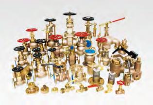
76 NAJIN FIE OF BUSINESS
Stainless Steel / Iron Valve ISO 9001
 CAST IRON GATE VALVE CLASS 125 NON-RISING STEM. (N.R.S.) STEM: SS410 (BRASS / SS304) MODEL: CI-12N (CI-12N/CI-2NS) CAST IRON GATE VALVE CLASS 125 OUTSIDE SCREW AND YOKE. STEM: SS410 (BRASS / SS304) MODEL:
GLOBE VALVE APPLICATION
 SPECIFICATION GOBE VAVE APPICATION Globe valves are primarily use as control valves where throttling or both throttling an shut-off are require. Globe valves can also be use for on-off service; however,
Cast Steel Valve Index
 Cast Steel Valve Iex GATE VAVES O.S. & Y. CASS FANGE FIGURE NO. BUTT-WE FIGURE NO. PAGE 150 2 1550CB2 1552CB2 1 150 14 24 1550CB2 1552CB2 2 300 2 3050CB2 3052CB2 3 300 10 24 3050CB2 3052CB2 4 600 2 6 6050CB2
BS 1452 Gr Gr. 420/ Gr. 420/ AB2 304 C C S S S S16. E mm
 WAFER TYPE BUTTERFY VAVE SPECIFICATION FOR BS EN 1092-2 PN10 / PN16 FANGE MOUNTING FACE-TO-FACE DIMENSION TO ISO 5752 / BS 5155 / BS EN 593 EVER / WORM GEAR OPERATOR PRESSURE / TEMPERATURE RATINGS BFV-WB
Cast Iron Valves. JIS 5K/10K, Class 125
 Valves JIS K/K, Class STNDRD PRODUCTION RNGE Valve Type Nominal Pressure Fig. No. Construction (Note) Page Gate valves JIS K JIS K JIS K JIS K JIS K K Class Class Class Class FCM FCL FCLS FCLU FCWI FCHI
CHECK VALVES DUAL PLATE CHECK VALVES (DC SERIES) NOZZLE CHECK VALVES (NC SERIES)
 NOZZLE CHECK VALVES (NC SERIES)") CHECK VAVES DUA PATE CHECK VAVES (DC SERIES) NOZZE CHECK VAVES (NC SERIES) eading Korean valve manufacturer DUA PATE CHECK VAVE (DC SERIES) Range Size Fluid Application 1 1/2 (40A) ~ 84 (2100A) Water,
CHECK VAVES DUA PATE CHECK VAVES (DC SERIES) NOZZE CHECK VAVES (NC SERIES) eading Korean valve manufacturer DUA PATE CHECK VAVE (DC SERIES) Range Size Fluid Application 1 1/2 (40A) ~ 84 (2100A) Water,
Tube & Pipe Division
 Tube & Pipe Division Cu-Ni / Brass / Al-Brass / Copper CONTENTS 01 GREETINGS 02 HSE STATEMENT 03 MANUFACTURING PROCESS 04 COMPANY PROFILE 05 QUALITY 06 ~ 07 PRODUCTS 08 EUROPE STANDARD 09 USA STANDARD
ANSI VALVE CATALOGUE
 ANSI VAVE CATAOGUE GATE VAVES GOBE VAVES CHECK VAVES BA VAVES BUTTERFY VAVES SYSTEMS AND PRODUCTS FOR INDUSTRIA CARGO TRANSFER AND STORAGE ANSI VAVE CATAOGUE Introuction CTS has evelope itself into a reputable
Cast Iron Valves. Product Information. It s all at Albion
 Cast Iron Valves Product Information It s all at Albion ART 77-78 Cast Iron Ball Valve Flanged Ends Flange Mounting PN16 Only ISO 5211 Direct Mount (Not 200mm) Art 77/78 Plated Brass/Stainless Ball BS
CHECK VALVE P.147 SWING CHECK VALVE P.149 WAFER CHECK VALVE P.151 BALL CHECK VALVE P.153 TRUE UNION BALL CHECK VALVE P.155 BALL FOOT VALVE
 CHECK VAVE P.47 P.49 P.5 P.53 P.55 SWING CHECK VAVE WAFER CHECK VAVE BA CHECK VAVE TRUE UNION BA CHECK VAVE BA FOOT VAVE 45 PERFORMANCE OF SWING CHECK VAVE, BA CHECK VAVE, AND BA FOOT VAVE Min. Pressure
I N F L O W S Y S T E M S VALVULA DE RETENCIÓN
 PROUC TOS Y SOUCIONES EN REES E FUIOS PROUCTS AN SOUTIONS I N F O W S Y S T E M S VAVUA E RETENCIÓN CHECK VAVE Index 0 0 0 0 07 08 09 0 7 8 0 Features of ual Plate R wafer dual plate check valve R0 class
SAFETY RELIEF VALVE STEAM TRAP GLOBE & ANGLE VALVE PRESSURE REDUCING & REGULATING VALVE OTHER VALVES
 www.ynv.co.kr SAFETY RELIEF VALVE STEAM TRAP GLOBE & ANGLE VALVE PRESSURE REDUCING & REGULATING VALVE OTHER VALVES Company Profile Greetings! This is the CEO of YNV Co. Ltd. Ever since our company was
ASME Classes /2 24 ( mm) Class /2 1 1 /2 (15 40 mm)
 Class /2 1 1 /2 (15 40 mm)") ASME Classes 150 300 1 /2 24 (15 600 mm) Class 800 1 /2 1 1 /2 (15 40 mm) PROFILE Velan is one of the world's leading manufacturers of industrial valves, supplying forged and cast steel gate, globe, check,
ASME Classes 150 300 1 /2 24 (15 600 mm) Class 800 1 /2 1 1 /2 (15 40 mm) PROFILE Velan is one of the world's leading manufacturers of industrial valves, supplying forged and cast steel gate, globe, check,
Direct Mount Packages
 800.783.7836 Direct Mount Packages BEV9 Actuated package Size range: 1/ - Pressure rated for 1000 WOG 316 Stainless steel construction Live loaded stem seal design Full Port Threaded Ends (F) EZ99 Actuated
Wellhead Valves. DHV Industries,Inc. DHV Valve Company Inc.
 DHV Industries,Inc. 3451 Pegasus Drive, Bakersfield. CA 93308 U.S.A. Call TollFree: (887) DHV-USA1 Phone: (661) 392-8948 Fax: (661) 392-8947 E-mail: sales@dhvindustries.com Website: www.dhvindustries.com
VALVES 5
 info@ayvaz.com www.ayvaz.com GLOBE VALVES GV-16, GV-25, GV-40 GV-16 GV-25 GV-40 GG-25 Cast Iron GSC-25 Cast Steel GSC-25 Cast Steel Seat Stainless Steel AISI 304 Stainless Steel AISI 304 Stainless Steel
700E Wafer with support lugs 700K Wafer with support lugs 700S Wafer with support lugs
 Large Diameter Rubber Seat Butterfly Valves for General Use E Wafer with support lugs Wafer with support lugs Wafer with support lugs Worm Gear Pneumatic Cylinder Motorized Features and Benefits Simple
NEWAY VALVE. Complete Solutions for Engineered Valves. Distributed by:
 Cat.no.:EGGC Forged Steel Valves Complete Solutions for Engineered Valves Cat.no.:EPV Cat.no.:EAV istributed by: No. Xiangjiang Road, Suzhou New istrict,p.r. China Post Code: Tel: Fax: 0 EMail: neway@neway.com.cn
CAST STEEL FLANGED GATE, GLOBE, & CHECK VALVES.
 CAST STEEL FLANGED GATE, GLOBE, & CHECK VALVES www.fnw.com Index Options & Accessories... 2 Standards... 2 Figure Number Matrix... 3 Pressure/Temperature Ratings... 3 Hydrostatic Test Pressures... 3 Carbon
CHECK valve SPECIFICATION. glt valves CHECK VALVE APPLICATION MANUFACTURING STANDARDS
 CECK VAVE APPICATION SPECIFICATION Sometimes referre to as non-return valve, check valves prevents back-flow, constantly keeping flow in one irection. Check valve are esigne to close quickly an automatically
Norflow Controls Industrial Valves
 MATERIAL OF CONSTRUCTION FOR PRESSURE CONTAINING PARTS FOR TRIM MATERIAL Carbon Steel Forged A-105 13% Cr. Steel A-217 Gr. CA15 Carbon Steel Cast A-216 Gr. WCB, WCC AISI 10 0.15% Moly Steel Cast A-217
Valves for building. Y-strainers... page 204 PVC valves Ball valves... page 204 Butterfly valve... page 204 Ball check valve...
 Valves for building Ball valves PN25/20... page 194 PN30/20... page 195 PN40/30 - Lead-free brass... page 196 Valve for gas... page 197 Stem extension valves... page 197 3 way valves... page 197 Mini valves...
CV-SFS4-PN16 SERIES SLIENT CHECK VALVE, GLOBE TYPE FEATURES SPECIFICATIONS PRODUCT IDENTIFICATION SYSTEM PRODUCT DATA
 CV-SFS4-PN16 SERIES SLIENT CHECK VALVE, GLOBE TYPE Silent check function Temperature -10 ~ +120 PRODUCT IDENTIFICATION SYSTEM 2 Disc Ductile iron GGG 40 3 Spring Stainless steel SUS304 4 Bush Bronze 1400
Trunnion Ball Valve Catalogue
 Trunnion Ball Valve Catalogue Introduction "Fusion" is the registered trademark of Archmetal Industries, a member of the Fortune Group. * The Fortune Group is a world class producer of a full range of
Champion Valves, Inc. DUAL DISC SPRING LOADED WAFER CHECK VALVES
 Champion Valves, Inc. DUAL DISC SPRING LOADED WAFER CHECK VALVES FEATURES Light weight, versatile design 80% to 90% less than conventional full-body swing check valves Dual Disc open to 80 degrees Spring-loaded
Brass, Bronze, Iron and Stainless Steel Valves
 Price Schedule June 1, 2011 Supersedes BIV-01-11 07 Brass, Bronze, Iron and Stainless Steel Valves ASTM B283 FORGED BRASS SCREW-IN BONNET NON-RISING STEM SOLID WEDGE DISC 125 WSP/200 WOG BRONZE GATE VALVES
Approved. Size L H. 3" (76mm) 9-1/2" (241mm) 5-51/64" (147mm) 46. 4" (102mm) 11-1/2" (292mm) 6-45/64" (170mm) 81
 9-1/2 (241mm) 5-51/64 (147mm) 46. 4 (102mm) 11-1/2 (292mm) 6-45/64 (170mm) 81") pproved. Model: SD-NRV200CV Flanged Ends The Flanged End Check Valves are made of Iron Body, Bolted Bonnet and Horizontal Swing, painted with standard color. Epoxy coated inside and outside to WW C550
pproved. Model: SD-NRV200CV Flanged Ends The Flanged End Check Valves are made of Iron Body, Bolted Bonnet and Horizontal Swing, painted with standard color. Epoxy coated inside and outside to WW C550
Valves for building. Y-strainers... page 272 PVC valves Ball valves... page 272 Butterfly valves... page 272 Ball check valves...
 Valves for building Ball valves PN25/20... page 262 PN30/20...pages 262 to 263 PN40/30 - Lead-free brass... page 264 Valve for gas... page 265 Stem extension valves... page 265 3 way valves... page 265
HS VALVE HS VALVE CO., LTD.
 HS VALVE HS VALVE CO., LTD. GREETING HS Valve co., ltd. was funded in 1987 with a mandate to become a world class manufactured of Ball, gate, globe & check Valve to meet the high standards of the Oil and
Industrial Bronze and Iron Price List
 Industrial Bronze and Iron Price List TABLE OF CONTENTS IND-0217 Effective: February 1, 2017 Revised: 12/07/17 Suggested list prices are subject to change without notification. Visit our Website for the
Contents. The Company Page 4. Female Lever Valves Page 5. Female Gate Valves Page 6. Bronze Gate Valves Page 7. Angle Valves Page 8-9
 VALVES CATALOGUE Contents The Company Page 4 Female Lever Valves Page 5 Female Gate Valves Page 6 Bronze Gate Valves Page 7 Angle Valves Page 8-9 Float Valves Page 10-11 Foot Valves Page 12 Spring Check
Inte rated. Piping. Manufacturer & Exporter: A Government of India Recognized Star Export House PIPES TUBES ROUND BAR PLATES SHEETS
 ISO 9001-08 ISO 14001-04 OHSAS 18001-07 PE-97/23/EC Certified Company RINA M A R I N E Approved Manufacture PIPES UBES ROUN BAR PLAES SHEES Inte rated Manufacturer & Exporter: A WORL OF FERROUS & NON -
Industrial Bronze and Iron Price List
 Industrial Bronze and Iron Price List TABLE OF CONTENTS IND-0718 Effective: July 2, 2018 Revised: 08/06/2018 Suggested list prices are subject to change without notification. Visit our Website for the
Industrial Bronze and Iron Price List
 Industrial Bronze and Iron Price List IND-0318 Effective: March 1, 2018 Revised: 08/06/2018 Suggested list prices are subject to change without notification. Visit our Website for the most up-to-date product
Industrial Bronze and Iron Price List
 Industrial Bronze and Iron Price List IND-0718 Effective: July 2, 2018 Revised: 09/24/2018 Suggested list prices are subject to change without notification. Visit our Website for the most up-to-date product
Single Seated Globe Control Valves
 Product 1: Top Guided Single Seated Control Valves Type: Globe Size: 1-1/2'', 2'', 2-1/2'', 3'', 4'', 6''and 8 (DN40 DN200) Pressure Rating: ANSI 125 ~ ANSI 600 (PN16~PN64, JIS10K~JIS40K) Body Material:
Soft Seat Knife Gate Valve
 CP KWWA www.dh-valve.co.kr Soft Seat Knife Gate Valve for Water Works Donghae Co., Ltd. Donghae Co., Ltd. DONGHAE We will come closer to our customers with advanced technology and quality. Donghae Co.,
HYDRAULIC CONTROL VALVES
 HYDRAULIC CONTROL VALVES The automatic control valves are diaphragm valves designed to provide hydraulically driven solutions to pressure, flow and level control applications. Features: Main valve uses
NON RETURN BRASS FLANGED AGA GAS APPROVED
 NON RETURN BRASS FLANGED AGA GAS APPROVED ACTUATED MARINE STAINLESS STEEL 34 VALVES 36... BRASS BALL VALVES 37... AGA GAS APPROVED VALVES GATE VALVES 38... BRASS VALVES 39... RUBBER BELLOW, HOSECOCKS &
D I S T R I B U T E D V A L V E S. TECHNO Short Form Wafer Style Check Valves TECHNO
 TECHNO Short Form Wafer Style Check Valves SHORT FORM WAFER STYLE CHECK VALVES Technocheck Short Form (SF), Cost Efficient, Reliable, Wafer Style Check Valve CLAMP PLATE SUPPORT Non-Slam Quick Closure
BERMAD Fire Protection
 Differential-Pressure Sustaining Valve Description The Model FP-436 Differential-Pressure Sustaining Valve is a hydraulically-operated, diaphragm-actuated, control valve that sustains minimum pre-set,
GVER04 GLOBE VALVE. Fundamental Of Engineering Data. Fundamental Of Engineering Data 14.04
 GVER04 14.04 GLOBE VALVE Fundamental Of Engineering Data Fundamental Of Engineering Data INDEX 03 04 05 06 07 PRODUT FEATURES MODEL SELECTION GUIDE GLOBE VALVE ASSEMBLY DIMENSION KS/JIS 10K RF, ANSI CL
Industrial Bronze and Iron Price List
 Industrial Bronze and Iron Price List TABLE OF CONTENTS IBI-1017 Effective: October 2, 2017 Revised: 12/07/2017 Suggested list prices are subject to change without notification. Visit our Website for the
Established in 1982, Modentic Industrial Corporation is involved in the world of stainless steel valves & fittings selling.
 Modentic Industrial Corp. ISO 9001 Certified. Established in 1982, Modentic Industrial Corporation is involved in the world of stainless steel valves & fittings selling. Contents A view of valve process
CAST STEEL GATE VALVE
 CAST STEEL GATE VALVE DESIGN CHARACTERISTICS OF API00 CAST STEEL GATE VALVE The design of thrust bearing makes valve opened easily and flexibly. Handwheel Nut Handwheel Stem Nut Retainer Stem Nut Lubricating
Forged Steel Valve Complete Solutions for Engineered Valves
 Forged Steel Valve Complete Solutions for Engineered Valves NEAY VAVE Cat.no.:EFSV0 Table of Contents Introduction Quality Commitment ~ Products Views ow to Order Complete Solutions for Engineered Valves
PRODUCT CATALOG
 PRODUCT CATALOG www.wosupply.com 800.962.9696 INDEX GATE VALVES Bronze Cast Iron Ductile Iron Cast Ste.el Forged Steel Metric Stainless Figure numbers are presented for many of our Items-however we are
UREA SERVICE FORGED VALVES
 UREA SERVICE FORGED VALVES 288 UREA SERVICE VALVES 289 UREAvalves DROP CHECK VALVE UREA SERVICE PN325 1/2 to 2 DOUGLAS CHERO DROP CHECK VALVE UREA SERVICE DROP CHECK VALVE UREA SERVICE PN325 : PN325 Drop
Quality, Safety and Environment
 Quality, Safety and Environment Global Valve Center B.V. is an independent, internationally operating, modern, flexible and service-oriented organization with over forty years of experience and expertise
KO Series. Cast Steel Gate Valves
 FEATURES & BENEFITS Body and bonnet of Class 150 - Class 900 gate valves are usually connected with studs and nuts. The body and bonnet of Class 1500 - Class 2500 gate valves are usually a pressure sealed
Pressure Relief Valves Series. Consolidated Safety Valve
 Pressure Relief Valves 1511 Series Consolidated Safety Valve Consolidated Type 1511 safety valves are designed for low pressure, steam heating boilers and steam generators as well as air service applications.
HP Air Product line for Defence & Marine Applications
 HP Air Product line for Defence & Marine Applications began 20 years ago as a specialty forging company providing custom technical FF solutions in specialty materials to solve our clients most demanding
K-BALL BALL VALVES FOR INDUSTRIAL AND PROCESS APPLICATIONS
 A comprehensive range of ball valves to suit a wide variety of industrial applications FEAURES he range includes one, two and three piece ball valve designs with screwed, weld or flanged end connections.
STANDARDS and SPECIFICATIONS
 ANSI (American National Standards Institute) ANSI B31.4 - Liquid petroleum transportation piping system. ANSI B31.4 - Gas transmission and distribution piping system. API (American Petroleum Institute)
ASSEMBLY 7 BITE TYPE FITTINGS. check the direction of sleeve. assemble the NUT with hand. apply the oil to the inside and outside of Body.
 ese excellen proucs assemble wi specially ea reae sleeves an boies mae from low carbon seel(s0c o S25C)o preven leaks. ese fiings are available wi various en sizes. Working Pressore 25MPa JIS B235- AFX
Thread Forming Technology for Light Metals
 Thread Forming Technology for Light Metals Cost & Design Savings Advantages High joint strength Safety against dynamic loads Consistently high clamp loads Self-locking vibration resistance Easy lead-in,
Air Operated Valve Control Valve
 Air Operated Valve Control Valve -1 Step 0 Type/Structure/Features Please refer to this for structure and feature of Air Operated Valve and Control Valve. Step 1 Selection Please look at the ID chart to
PNEUMATIC ON OFF GLOBE VALVE
 PNEUMATIC ON OFF GLOBE VALVE Model No. AGE0 SERIES s Bonnet -way globe valve, -way globe valve 1A(1/") ~ 00A(1") JIS 10K~K, ANSI 10#~900#, PN10~, etc. FF, RF, BW, SW Plain bonnet: -17 ~0 Extended bonnet:
ANSI Valve Standards. API Valve Standards
 ANSI Valve s ANSI - the American National s Institute standardization and conformity assessment system. Code Name ANSI A126 ANSI A181 ANSI 816.10 ANSI 816.34 ANSI 8127.1 Grey iron castings for valves flanges
516509_tabs 11/16/10 4:55 AM Page 1 FIRE HYDRANTS
 Date Printed: November 2010 FIRE HYDRANTS or Tyton (6"),6, or 8" A EDDY FIRE HYDRANTS PARTS LIST WORKING PRESSURE: 150 PSI Note: Discontinued For Reference Only 350 PSI Working Pressure
Temperature Regulators
 Temperature Regulators DESIGN & OPERATION DIAL THERMOMETER (Model 91400 only) BELLOWS OVERRANGE PROTECTION SPRING CAPILLARY TUBING CONNECTION SENSING BULB RANGE ADJUSTMENT SPRING CAP ADJUSTMENT SCREW BUSHING
1324 Cypress Avenue P.O. Box Los Angeles, CA (800) FAX (323)
 FAX (323)") 1324 Cypress venue P.O. Box 65587 os ngeles, C 90065-1220 www.culvervalve.com (800) 421-6136 FX (323) 222-1223 CU COMPY Brief History of Culver Co. B O F C O Culver Co. was started in 1962 as a direct
1324 Cypress venue P.O. Box 65587 os ngeles, C 90065-1220 www.culvervalve.com (800) 421-6136 FX (323) 222-1223 CU COMPY Brief History of Culver Co. B O F C O Culver Co. was started in 1962 as a direct
OSV. Forged Steel Valves Technical book OSV
 OSV Forged Steel Valves Technical book OSV Principles Of Company General Introduction Company History About the company OS Valves (OSV) is a subsidiary of OS Company. OSV has been inspiring our employees
CHAMPION WAFER CHECK VALVES SIZE RANGE 2" 72" ASME CLASS MATERIALS: IRON CARBON STEEL STAINLESS STEEL ALUMINUM BRONZE ALLOY 20 MONEL NICKEL
 CHAMPION WAFER CHECK VALVES SIZE RANGE 2" 72" ASME CLASS 125 2500 MATERIALS: IRON CARBON STEEL STAINLESS STEEL ALUMINUM BRONZE ALLOY 20 MONEL NICKEL CHAMPION VALVES, INC. DUAL DISC SPRING LOADED WAFER
CLASS 400 FORGED BRASS BALL VALVE
 CLASS 400 FORGED BRASS BALL VALVE FIG. 214 Screwed body cap, PTFE seats, Blowout-proof stem. Screwed ends to BS 21. Nickel plated body. Chrome plated ball. UNI-FLO NYLON BALL VALVES FIG. 214NS/NB Features:
JIS & DIN. United States. Canada. Europe
 United States Mobile, Alabama 4766 Rangeline Rd. Mobile, AL 36619 251.433.2816 251.438.1210 fax mobile.al@wosupply.com Houma, Louisiana 101 Capital Blvd. Houma, LA 70360 985.772.7010 985.876.4960 fax houma.la@wosupply.com
SUBMITTAL PACKAGE FIRE PROTECTION VALVES
 SUBMITTAL PACKAGE FIRE PROTECTION VALVES Butterfly Valves Ductile Iron Grooved...pg 2-5 Grooved Check Valves...pg 6-8 OS&Y Valves...pg 9-12 ARGCO.com 800-854-1015 Updated 2/27/2017 ARGCO GROOVED BUTTERFLY
A. American National Standards Institute: 1. ANSI Z Relief Valves for Hot Water Supply Systems.
 SECTION 220523 - PLUMBING VALVES PART 1 - GENERAL 1.1 SUMMARY A. Section Includes: 1. Ball valves. 2. Butterfly valves. 3. Swing check valves. 4. Spring loaded check valves. 5. Water pressure reducing
(ST-B1 / ST-B2 / ST-B3 / ST-B4) CAST IRON INVERTED BUCKET STEAM TRAP
 CAST IRON INVERTED BUCKET STEAM TRAP") (ST-B1 / ST-B2 / ST-B3 / ST-B4) CAST INVERTED BUCKET STEAM TRAP ST-B1B2 ST-B3 ST-B4 (ST-B1 / ST-B2 / ST-B3 / ST-B4) CAST INVERTED BUCKET STEAM TRAP MATERIAL PARTS Cap and Body Valve Seat Valve Gasket Material
(ST-B1 / ST-B2 / ST-B3 / ST-B4) CAST INVERTED BUCKET STEAM TRAP ST-B1B2 ST-B3 ST-B4 (ST-B1 / ST-B2 / ST-B3 / ST-B4) CAST INVERTED BUCKET STEAM TRAP MATERIAL PARTS Cap and Body Valve Seat Valve Gasket Material
Brass, Bronze, Iron and Stainless Steel Valves
 Price Schedule June 1, 2015 Supersedes BIV-06-11 CLASS 125 07 Brass, Bronze, Iron and Stainless Steel Valves ASTM B283 FORGED BRASS SCREW-IN BONNET NON-RISING STEM SOLID WEDGE DISC 125 WSP/200 WOG BRONZE
SECTION GENERAL-DUTY VALVES FOR HVAC. A. Section includes valves for building services piping.
 SECTION 23 05 23 GENERAL-DUTY VALVES FOR HVAC PART 1 - GENERAL 1.1 SUMMARY A. Section includes valves for building services piping. 1.2 REFERENCES A. AGA Z21.22 (American Gas Association) - Relief Valves
Valves. BS Standard JINAN MEIDE CASTING CO., LTD.
 Valves BS Standard JINAN MEIDE CASTING CO., LTD. Resilient Wedge Gate Valve XZ81X Grooved Resilient OS&Y Gate Valve Page 11 XZ51X Flanged x Grooved Resilient OS&Y Gate Valve Page 12 Z85X Grooved Resilient
Approved Branded Traceable Fire Protection & Waterworks Valves
 Approved Branded Traceable Fire Protection & Waterworks Valves (800) 766-0076 www.smithcooper.com Los Angeles, CA Atlanta, GA Vancouver, WA Chicago, IL AWWA C515 Compliant CONSIDER Your Options Tamper
Brass, Bronze, Iron and Stainless Steel Valves
 Price Schedule January 1, 2018 Supersedes BIV-06-15 Brass, Bronze, Iron and Stainless Steel Valves 07 BRONZE GATE VALVES CLASS 125 ASTM B283 FORGED BRASS SCREW-IN BONNET NON-RISING STEM SOLID WEDGE DISC
GWC Italia. Proven technology for individual valve solutions worldwide FSV-1005
 GWC Italia Proven technology for individual valve solutions worldwide forged STEEL VALVES GATE, GLOBE & CHECK FSV-1005 2 GWC ITALIA Proven technology for individual valve solutions worldwide w w w. g w
The excellent performance of the pressure seal type range, is optimal in high pressure and high temperature applications.
 The excellent performance of the pressure seal type range, is optimal in high pressure and high temperature applications. Features Swing check valves can fit on both horizontal and vertical (up-flow) piping.
P R E C I S I O N E N G I N E E R E D C H E C K V A L V E S
 P R E C I S I O N E N G I N E E R E D C E C K V A L V E S SERIES X EXTENDED BODY CECK VALVE PARTS LIST ITEM PART NAME 1 BODY 2 SEAT INSERT 3 FLAPPER 4 SPRING 5 SPRING PIN 6 SEAT SEAL IG PERFORMANCE IG
ND = Double Door, SEAT NBR ES = Center Guided Silent Check / EPDM NS = Center Guided Silent Check / NBR. Butterfly Valves, Seat in body.
 MAS-WDI-1118 MAS W-Series Water Works / Fire Protection Valves ORDERING CODES Series XX = Valve Type X = CWP XX = Design Type XX = End Connection W = AWWA/UL/FM, 10 = Gate Valve A = 300 CWP RS = Rising
RAIMONDI. High pressure forged globe valves to guarantee the pressure envelope integrity on harsh services.
 Fig. 6022-6025 RAIMONDI High pressure forged globe valves to guarantee the pressure envelope integrity on harsh services. Features Forged body materials of highest quality, all in compliance with ASME
Wafer, Semi Lug, Lug and Flanged Type
 Year : Wafer, Semi Lug, Lug and Flanged Type Page 1 Year : Specification Description : GVC concentric rubber lined butterfly valves suitable for bi-directional flow and bubble tight shut-off at full rated
HVAC. Products. TRI A FLO Automatic Cartridges PAGE 2. TRI Y FLO Strainer PAGE 3. TRI U FLO Accessory Union PAGE 4. CB Series Butterfly/Venturi PAGE 5
 HVAC TRI A FLO Automatic Cartridges TRI Y FLO Strainer TRI U FLO Accessory Union Products Automatic balancing valves.5 thru 108.0 in Brass, Stainless, PVC, CPVC, Titanium, Ceramic, Monel, and more PAGE
BS 5163 Resilient Wedge Gate Valve
 BS 516 Resilient Wedge Gate Valve BS 516 Flanged Resilient OS&Y Gate Valve, Type A, (XZ41X), /16, Gate valves serve to cut the medium flow in the piping system, widely used in the field of potable water,
THROUGH CONDUIT VALVES TECHNICAL CATALOGUE
 SITINDUSTRIE VALVO VALVES THROUGH CONDUIT VALVES Ed. 01/DIC-2004 SITINDUSTRIE reserves the right to change, without notice, 1/14 SITINDUSTRIE TRIE VALVE DIVISION We are pleased to introduce you to the
Floating Ball Valve - Design Features
 408 imbledon Rd. / Edmond, OK 73003 / Phone: 405-509-2665 / Fax: 866-239-1587 / www.mako-products.net Flanged Ball Valves Floating Ball Valve - Design Features Mounting and Stem Seal Design Actuator Mounting
DUTCH VALVE COMPANY SINCE
 DUTCH VALVE COMPANY SINCE 1956 1 Contents Company Introduction Manufacturing Capacity Product Range Certificates & Approval Bonded Vs Replaceable Liner Area of Applications Our Strength Project Reference
AVK DOUBLE ECCENTRIC BUTTERFLY VALVE, PN 10/16, INTEGRAL SEAT, IP 67 GEARBOX WITH HANDWHEEL
 AVK OUBE EENTRI BUTTERFY VAVE, PN 10/16, INTEGRA SEAT, IP 67 GEARBOX WITH HANWHEE 00 019 ouble eccentric butterfly valve, for water to max. 70, designed according to EN 593, Face to face according to EN
BUTTERFLY VALVE VF-7 Series
 BUTTERFLY VALVE VF-7 Series CENTRIC, RUBBER SEATED LEVER GEAR PNEUMATIC - ELECTRIC OPERATED ALLOWABLE PRESSURE DN 40 300mm : 16 bar DN 350 1200mm : 10 bar INVESTMENT CASTING STAINLESS STEEL BODY 2 12 (50mm
GWC Italia. Proven technology for individual valve solutions worldwide API 6D SWING CHECK VALVES SC-1002
 GWC Italia Proven technology for individual valve solutions worldwide API 6D SWING CHECK VALVES SC-1002 GWC ITALIA Proven technology for individual valve solutions worldwide GWC Italia Worldwide Network
Large bore valves. Powergeneration / petrochemical industries. Medium & high-pressure valves in accordance with ASME, EN, BS and API
 Large bore valves Powergeneration / petrochemical industries Medium & high-pressure valves in accordance with ASME, EN, BS and API An introduction to Key Valve Technologies Ltd. Key Valve Technologies
Sempell High Pressure Stop Valves Model VA500 (ASME)
") 7 Sempell High Pressure Stop Valves Designed for the isolation and control of high temperature and high pressure systems, this multipurpose globe valve can be used in a wide variety of applications. Features
7 Sempell High Pressure Stop Valves Designed for the isolation and control of high temperature and high pressure systems, this multipurpose globe valve can be used in a wide variety of applications. Features
Hattersley Newman Hender Ltd
 Product Guide Quality Valves from Hattersley WHEN IT REALLY COUNTS, YOU CAN DEPEND ON HATTERSLEY Hattersley Newman Hender is one of the world s premier manufacturers of cast iron, ductile iron and copper
TECHNICAL DATASHEET Pacific CSV Cast Steel Valves
 brands you trust. TECNICA DATASEET Pacific CSV Cast Steel Valves Crane ChemPharma & Energy Gate, Globe and Check Features and Benefits The new Pacific CSV valves have been redesigned to improve performance
CORRIGENDUM - II. Sr.No. Price Break Up ---- Rate For item No.-1 to item No.-19.
 CORRIGENDUM - II No. 6000003469/M.E.03/ Dated : 28/03/2014 Ref: Tender Enquiry No. 6000003469/M.E.03/2235 data 18.12.2013 Against our above tender enquiry was published in the http://spmhoshangabad.spmcil.com
Valves Range RVRX - Resilient Seated Gate Valve PN16 Flange
 Valves Range RVRX - Resilient Seated Gate Valve PN16 Flange No Component Material 1 Body Ductile iron GGG40 2 Wedge DI Fully Vulcanised EPDM 3 Wedge Nut Brass 4 Stem SS420 5 Bolt Q235+Zinc 6 Gasket EPDM
TEL: Version: KW2
 WWW.KLAMBON.COM 1 Page Klambon Water is a wholly owned subsidiary of West Rand Engineering (WRE), we are suppliers of valves, fittings and related products to all industries and our service extends to
GENE RICH SPECIALTIES
 All s Final - No Returns Allowed Attn: Plumbing Specialties Buyers Limited Time for Super Savings on Select Items: Faucets and Supplies Compression Tees and Couplings Dielectric Unions Red, Yellow and
HAM-LET PRECISION INSTRUMENT PIPE FITTINGS
 HAM-E PRECISION INSRUMEN PIPE FIINGS PRECISION INSRUMENAION PIPE FIINGS GENERA HAM-E Group is pleased to introduce its line of Precision Instrument Pipe Fittings. he Pipeline range of connectors is manufactured
3-way Control Valves type G3F, Nodular cast iron PN 25, DN mm, Flanged ends
 3-way Control Valves type G3F, Nodular cast iron PN 25, N 20 65, Flanged ends 2.5.08-I GB-1 Characteristics Nominal pressure PN 25 Regulating capaility vs > 25 vr Same vs -value as mixing and diverting
KVC VALVES AND PEX FITTINGS
 KVC VALVES AND PEX FITTINGS 2011 KVC VALVES & PEX FITTINGS CATALOGUE 2 P a g e Table of contents 1. Cast Steel Valves..4 FIG. 272-CS-15 ( Gate ).....5 FIG. 272-CS-300 ( Gate )......6 FIG. 272-CS-600 (
PLANT KOREA. Contents
 Contents 1. Company outline 3. Handling Items 1. Company outline is Trading company & Network between Korean company and Customer. Business Scope: plant equipment / materials business in Korea such as