|
|
|
- Meryl Martin
- 5 years ago
- Views:
Transcription


1 Actuator ine Part 2 General catalogue English


2 When you move. We move Rollon S.p.A. was founded in 1975 as a manufacturer of linear motion components. Today Rollon group is a leading name in the design, production, and sale of linear rails, telescopic rails, and actuators, with headquarters based in Italy and offi ces and distributors located throughout the world. Rollon products are used in many industries, providing creative and effi cient solutions in a wide variety of applications. Rollon solutions for linear motion inear ine Telescopic ine Actuator ine Actuator System ine Actuator ine Actuator System ine Product Overview English inear ine Hegra Rail Actuator ine Sys Prismatic Rail inear Rails Telescopic Rails Actuators Solutions for industrial automation Rails with roller bearings Rails with caged ball bearings Rails with recirculating ball bearing Rails with partial/total extension Heavy duty rails Rails for automated and manual applications Belt driven actuators Ball screw driven actuators Rack and pinion actuators Multi-axis for pick and place Telescopic actuators Seventh axis for robots Solutions for metal sheet handling


3 Core Competencies Full range of linear rails, telescopic rails and actuators Worldwide presence with branches and distributors Fast delivery all over the world arge technical know-how for applications Standard solutions Collaboration Customization Wide range of products and sizes inear rails with roller and caged ball bearings Heavy duty telescopic rails Belt or ball screw driven linear actuators Multi-axis systems International know-how in several industries Project consultancy Maximizing performance and cost optimization Special products Research and development of new solutions Technologies dedicated to different sectors Optimal surface treatment Applications Aerospace Railway ogistics Industrial Medical Special Vehicles Robotics Packaging


4 Technical features overview Reference Section Driving Family Product Balls Rollers Toothed belt Ball screw Rack and pinion Anticorrosion Protection PAR TECINE PAS/M MCH MCR TVS TVH MODINE TCS TCH TECH KCH TCR TECR MVS MVH MVR ZCS ZCH MODINE Z ZCR ZCY ZMC Reported data must be verifi ed according to the application. For a complete overview about technical data, please consult our catalogues at * onger stroke is available for jointed version. ** When consulting the drawings in this catalog, always reference the legend listed on the same page.
![Size Max. load capacity per carriage [N] Max. static moment per carriage [Nm] F x F y F z M x M y M z Max. travel speed [m/s] Max. acceleration [m/s²] Repeatability accuracy [mm] Max.](/docs-images/81/83893952/images/5-0.jpg "travel or stroke (per system) [mm] 170-180-200 220-280-360 10280 29900 44860 6900 13160 8800 3,5 10 ± 0,2 10800* T 170-180-200 220-280-360 11600 47350 47350 7240 13100 13100 3,5 10 ± 0,05 10800*")
5 Size Max. load capacity per carriage [N] Max. static moment per carriage [Nm] F x F y F z M x M y M z Max. travel speed [m/s] Max. acceleration [m/s²] Repeatability accuracy [mm] Max. travel or stroke (per system) [mm] ,5 10 ± 0, * T ,5 10 ± 0, * ± 0, M ± 0, ± 0, ± 0, , ± 0, ,75 5 ± 0, ,75 5 ± 0, ± 0, M Z ± 0, ± 0, M z F z M x M y F y F x
6

7 Tecline


 reduced")


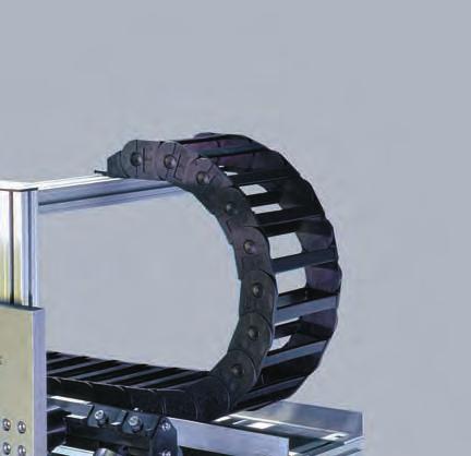
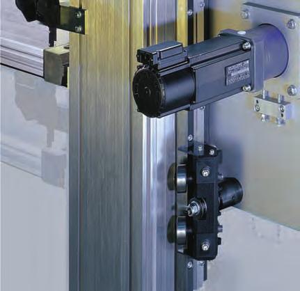
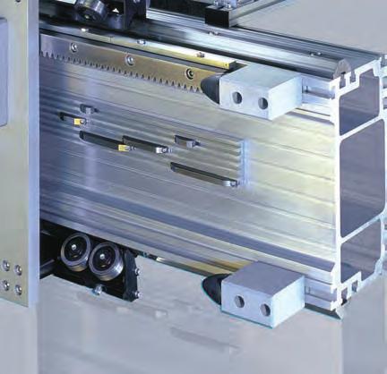
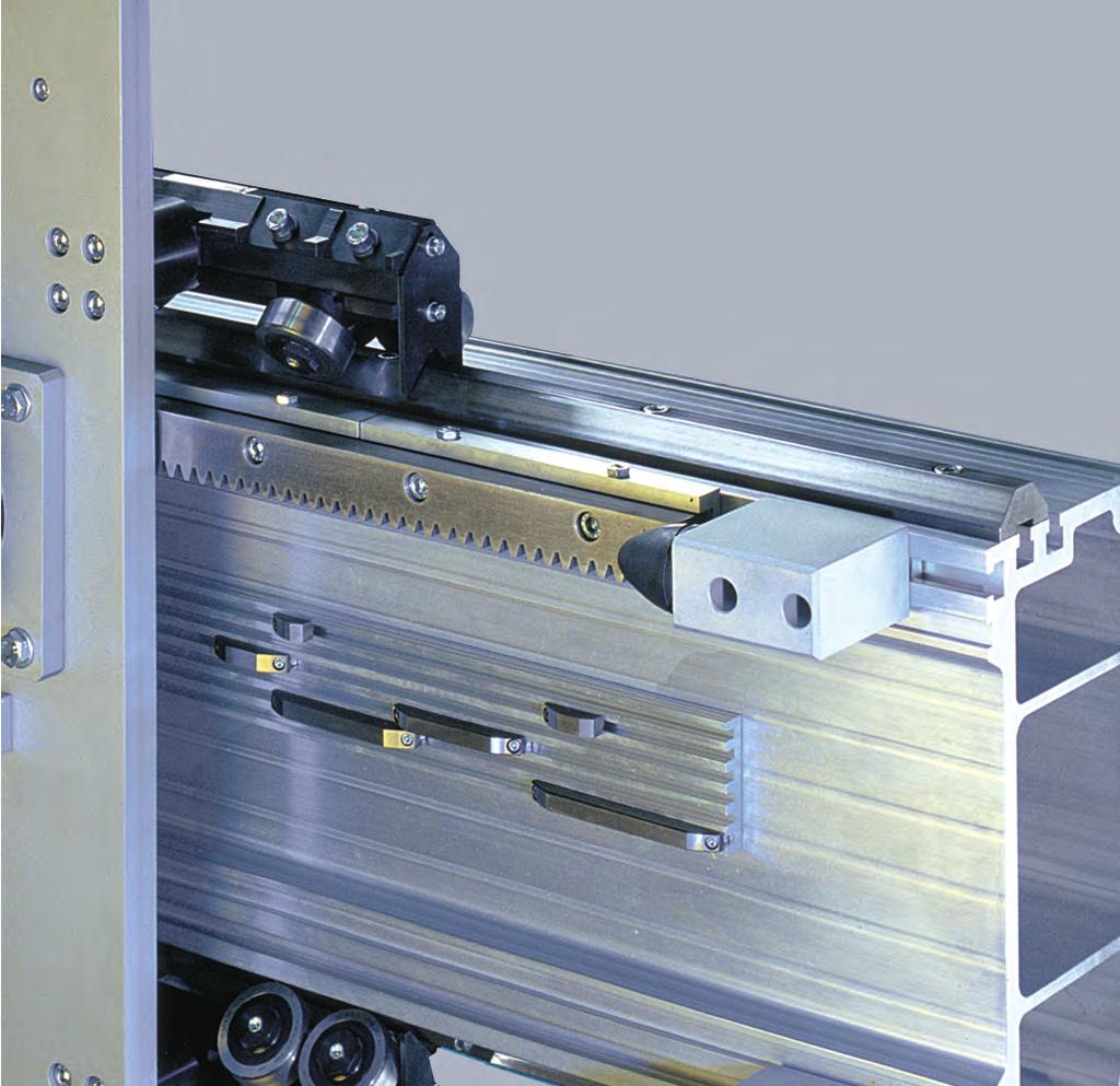
8 roller bearing Y-axis gear rack travel limit end stops aluminum profile structural beam main carriage plate Y-axis gear reducer mounting plate roller bearing V-guide Our tecline linear system range is suitable for the handling of loads from 10 up to 1000 kg, by manufaturing one or more axis systems according to the customer requirements. Our main application fields are: robotics, palletization, production line, logistics and manufacturing machines with Cartesian axis movements. Our products stand out for their: easy and quick assembly high quality and competitive performances (profiles up to 12 m) reduced and simplified maintenance wide range of integrated solutions possibility of customised solutions constant technical support and CAD drawings available Our Tecline linears strong points are: Solid beams obtained from aluminium alloy extruded profiles High-performance aluminium casting alloy plate and preset for tool assembly Adapting plate suitable for any commercial available gearboxes Fixed and oscillating roller slides, which can be adjusted through an eccentric bushing Without play and sealed rollers with a for life lubricating system Induction hardened and machined strong V-shaped steel guide rails Adjustable limit stops provided with rubber buffers Wide range of accessories for 3 or more axis linears
9 inear systems with rack drive and components INTRODUCTION Construction characteristics Preliminary selection table (1-2-3 axes) T-2 T-3 SINGE AXES DOUBE AXES PAR 1 - PAS 1 (180) T-4 PAR 2 - PASM 2 (170) T-6 PAR 3 - PASM 3 (200) T-8 PAR 4 - PASM 4 (200) T-10 PAR 5 - PASM 5 (220) T-12 PAR 6 - PASM 6 (280) T-14 PAR 8 - PASM 8 (280) T-16 PAR10 - PASM 10 (360) T-18 PAR 1/05 - PAS 1/05 (180/90) T-20 PAR 2/1 - PASM 2/1 (170/90) T-22 PAR 3/1 - PASM 3/1 (200/100) T-24 PAR 4/1 - PASM 4/1 (200/100) T-26 PAR 5/2 - PASM 5/2 (220/170) T-28 PAR 6/2 - PASM 6/2 (280/200) T-30 PAR 6/4 - PASM 6/4 (280/200) T-32 PAR 8/3 - PASM 8/3 (280/200) T-34 PAR 8/6 - PASM 8/6 (280/220) T-36 PAR 10/6 - PASM 10/6 (360/220) T-38 PAR 10/8 - PASM 10/8 (360/280) T-40 COMPONENTS Profiles specifications Steel V-Shaped guide rails Racks Adjusting plates for racks Pinion gears Alberi di collegamento Rollers for v-shaped guide rails 28.6X11 and 35x16 Roller slides Assembly Studs Order code table for roller slides and pins ock-pin (shock absorbers) T-42 T-46 T-48 T-49 T-49 T-50 T-51 T-52 T-58 T-59 T-60 ACCESSORIES This document replaces all previous editions. Due to the constant progress of our research we reserve the right to modify drawings or features without notice. No part of this catalogue may be reproduced without written permission of the copyright owner. All rights reserved. This catalogue has been accurately checked before publishing. However, we disclaim all responsibility in case of errors and omissions. Edition Profile anchor brackets -shaped brackets End caps for profiles Cams and cam-holders for micro-switches Threaded inserts for small and medium profiles Threaded inserts for load-bearing profiles Programmable automatic rack lubrication system Anti-drop device with pneumatic brake system Table for selecting maximun operating torque TECHNICA INSTRUCTIONS Instructions for correct assembly Accurancy - ubrication Assembly positions and load direction SIZING Standard assembly solutions Sizing template Technical data sheet Index T-60 T-61 T-63 T-64 T-65 T-66 T-68 T-68 T-69 T-70 T-71 T-72 T-73 T-74 T-75 T-76
10 Construction characteristics Multiple-axis linear modules with rack drive TECINE linear systems are designed for ROBOTS with one, two or three CARTESIAN AXES and comprise Rollon linear modules with rack drive, in different sizes depending on the load to be translated. Modules with rack drive are suitable for transfer and positioning systems with an extremely low repeatability error and/or for dynamic performance and heavy loads. They can be equipped / supplied with gearboxes. Whatever the application, the configuration can be adapted using the complete order code, within an extensive range of components (energy-chains, guides, micro-switches, lubrication units, etc.) and accessories. Our technical dept. is available to provide assistance with code setting. Beams Manufactured with Rollon s extruded and anodised (*) profiles, made of hardened and tempered aluminium alloy Al Mg Si 0.5, quality F25, Rm 245 N/mm, tolerance according to UNI EN Profiles are specifically designed by Rollon to create rigid and light structures, suitable for manufacturing linear transfer machines. The guide and rack housings on modules equipped with ball roller slides (PASM family) are milled. (*) Valyda and ogyca profiles are anodised up to 12 m. Pratyca and Solyda are anodised upon request Modules can be supplied with head-pieced beams, upon request Plates Manufactured with flattened extra-fine rolled sections made of high-performance casting alloy (tensile strength, Rm = 290 MPa, HB = 77). Standard plates can be machined according to drawings (code D). V-shaped guide rails, PAR version Made of specially treated high-carbon steel. Standard versions include induction hardened rails section 28.6x11, 35x16 and 55x25 (max. length 4000 mm). Joints bevel cut at an angle of 20. Roller slides, PAR version Body in aluminium alloy G A SI 91 hardened and tempered according to EN AB 46400, rollers with double rows of angular contact ball bearings, backlash-free, long life lubrication: Ø 30, Ø 40, Ø 52, Ø 62 mm rollers. Adjustable tolerance between rollers and guides. Complete with wiper scraper. Caged ball roller slides and guide rails, PASM version Systems are supplied with caged ball roller slides. The cage included in the slides has two purposes: it reduces the friction between the guide rail and the slide and prolongs their service life, and allows lubrication refills to be performed more rarely. The modules and guide rails are suitable for composing sections more than 10 m long. The assembled guide rails have a run parallelism of less than mm. The assembly of caged ball roller slides and guide rails normally also involves the machining of the related seat in the profile (code M). Racks / Toothed pinions Racks with helical teeth, made of induction-hardened steel and hardened and tempered alloy steel, are available with three different modules: m2, m3 and m4. PAR versions with guide rails and roller slides, assembled with ground, KSD induction-hardened racks with pinions in highperformance tempered and surface-hardened steel (RD). PASM versions with guide rails and caged ball roller slides, are normally assembled with KSD induction hardened racks with pinions in hardened and tempered RD steel. High-performance KRD racks are available upon request (Rs>900 MPa): hardened and tempered, induction-hardened, and fully ground (page T-48). With RD pinions, KRD racks and continuous lubrication, speeds of up to 5 m/s can be reached. Stop bumpers Important: the rubber stop bumpers provided with standard linear models are suitable and regarded as static limit switches. For special needs, such as stops if the drive breaks, please specify loads, dynamics, details and discuss the use of specific parts, accessories and devices (reinforced plates and attachments - shock absorbers, anti-drop devices, etc.) with our technical dept. Energy chains or accessories Energy chains are provided upon request, together with a wide range of accessories. Adjustable brackets and supports are included. Standard sizes are those shown in the catalogue. Energy chains and accessories can be added using the order code on page T-11. Anti-oxidation parts and coatings Rack modules with anti-oxidation coating are available upon request. Materials with special coatings and lubrication are selected according to the environment of use (food industry, health sector, marine environment, exposure to weather, etc.) Gearboxes Supplied upon request. The use of right-angle reduction gears with hollow shaft and key is recommended. With this configuration the gearbox adapting plate is complete with shaft, pinion and step bearing. Otherwise, upon request, the adapting plate can be machined according to customer specifications and the pinion, if obtainable from the standard version. Backlash between the pinion and rack is only adjusted if the gearbox is supplied (or available). T-2
11 Preliminary selection table (1-2-3 axes) Tecline These tables are useful for making a preliminary selection with load applied in a central position with respect to the plate or profile axis. Z axis length is < 1,600 mm. Deflection is computed assuming continuous beams having the same span and concentrated static loads. In the following table, select the appropriate X axes according to the load. PA 2X 3X 4X 5X 6X 8X 10X C Deflection 50 1, , ,7 1, ,3 2, ,3 2, ,8 1, ,5 1, , N.B. per i PA 8X e 10X verticale compensare il carico. Max load capacity [kg.] X-axis C T In the following table, select the appropriate Y-X axes according to the load. Max load capacity [kg.] PA 2/1 3/1 4/1 5/2 6/2 8/3 6/4 8/6 10/6 10/8 C Deflection 50 1, ,4 1,7 2 1, ,2 0,8 0, ,6 1,6 1, ,9 2 0, , ,5 1,2 1, , Y-Z-axes C In the following table, select the appropriate X and Y-Z axes according to the load. Y-Z-axes X-axis PA 2/1 3/1 4/1 5/2 6/2 8/3 6/4 8/6 10/6 10/8 PA load [kg.] X (200) 3X (300) 4X (400) 5X (500) 6X (600) 8X (800) 10X (1000) NB: The choice of X axis is based upon the actual load, the supporting points, max. deflection and the total weight of the Y-Z axes. EXAMPE: selection of 3-axis system with roller slides (Please see page T-72 and the system pages for the nomenclature) X-Y-Z-axes DATA: Total working load 300 kg, X axis stroke: 5,000 mm, Y axis stroke: 4,000 mm, Z axis stroke: 2,000 mm, support points: 2 By analysing the table of Y-Z axes based on the working load (Pc), profile length (y) and deflection, the selection falls on one PA 8/3 (load 300 kg.) system. Check: P eff = P max - (z - 1,600)/1,000 q z = 300-(2,870-1,600)/1, = kg. < di 300 kg (not sufficient). Therefore select the larger size PA 6/4 (max. load capacity 400 kg.) M toty+z PA 6/4 = M base +(q y strokeq y +q z strokeq z )/1000+Pc = 244+(66 4, ,000)/1, = 904 kg. P totx = M tot PA 6/4 (Y+Z) 0.66 = kg. x = stroke x + 1,200 = 5,000+1,200 = 6,200 mm By analyzing the table of X axes based on the load (P totx ) profile length (x) and deflection, it is possible to select 2 linear axes PA 6X Chosen composition: n 1 PA 6/4 + n 2 PA 6X Perform a final analysis by computing the deflection based on the actual size of the spans. Our technical dept. is at your complete disposal to help you examine the most suitable applications for your requirements and help you...with motor and drive sizing for the whole project. T-3
12 R150 PAR 1 P / A / R / R / 180 / Stroke / ength / PC 60 Kg 120 Kg High Cycle Rate ow Cycle Rate =Stroke Corsa Stroke Corsa * 117,5 20 * For indication only, variable according to the gearbox chosen Fy Performance X-axis Max. speed 3.5 [m/s] Max. acceleration 8 [m/s 2 ] Repeatability ± 0.05 [mm] Beam max. length without joint 8,000 [mm] Assembly positions and load direction, see page T-72 Recommended max working conditions Model M x [Nm] M y [Nm] M z [Nm] F x [N] F y [N] F z [N] PAR ,170 1,170 2,900 5,900 5,900 The values shown above include a safety coefficient for automated machinery. They refer to maximum performance with each force acting individually. In case of peak forces acting together please consult our technical dept. Construction data X-axis oad-bearing beam (see page T-42 to T-45) E01-5 Rack (hardened, helical teeth, ground: module KSD) module 2 Guide rail 28x11 (hardened) Translation 4 roller slides with 4 rollers Ø30 Room available for energy chain 115x45 approx. [mm] Pinion pitch diameter type RD (as an alternative 63.66) [mm] Weights X-axis Base model (stroke x =0) M base = 28 [kg] Slide (plates + carriages) M slide = 15 [kg] Beam (incl. guide rails and rack) q X = 19 [kg/m] Formula: Module total weight: M tot =M base +(q x stroke x )/1,000 Stroke x [mm] T-4
13 PAS 1 P / A / S / 180 / Stroke / ength / PC 60 Kg 120 Kg High Cycle Rate ow Cycle Rate Tecline =Stroke Corsa Stroke Corsa 45 R150 T * * For indication only, variable according to the gearbox chosen Fy Performances X-axis Max. speed 3.5 [m/s] Max. acceleration 10 [m/s 2 ] Repeatability ± 0.05 [mm] Beam max. length without joint 8,000 [mm] Recommended max working conditions Model M x [Nm] M y [Nm] M z [Nm] F x [N] F y [N] F z [N] PAS 1 1,250 3,450 3,450 2,900 16,950 16,950 The values shown above include a safety coefficient for automated machinery. They refer to maximum performance with each force acting individually. In case of peak forces acting together please consult our technical dept. The repeatability shown in the table can be achieved with a ground rack and low-backlash gearboxes. Construction data X-axis oad-bearing beam (see page T-42 to T-45) E01-5 Rack (hardened, helical teeth, ground: module KSD) module 2 Translation: 4 caged ball roller slides and guide rails Size 20 Room available for energy chain 115x45 approx. [mm] Pinion pitch diameter (induction-hardened, ground - RD) (as an alternative 63.66) [mm] Weights X-axis Base model (stroke x =0) M base = 27 [kg] Slide (plates + carriages) M slitta = 14 [kg] Beam (incl. guide rails and rack) q X = 19 [kg/m] Formules: Module total weight: M tot =M base +(q x stroke x )/1,000 Stroke x [mm] T-5
14 PAR 2 P / A / R / Q/ 170 / Stroke / ength / PC 80 Kg 250 Kg High Cycle Rate ow Cycle Rate =Stroke Corsa Stroke Corsa 150 R , * * For indication only, variable according to the gearbox chosen Fy Performance X-axis Max. speed 3.5 [m/s] Max. acceleration 10 [m/s 2 ] Repeatability ± 0.05 [mm] Beam max. length without joint [mm] Assembly positions and load direction, see page T-72 Recommended max working conditions Model M x [Nm] M y [Nm] M z [Nm] F x [N] F y [N] F z [N] PAR ,350 1,350 5,980 7,000 7,050 The values shown above include a safety coefficient for automated machinery. They refer to maximum performance with each force acting individually. In case of peak forces acting together please consult our technical dept. Construction data X-axis oad-bearing beam (see page T-42 to T-45) Statyca Rack (hardened, helical teeth, ground: module KSD) module 3 Guide rail 35x16 (hardened and polished) Translation 4 roller slides with 2 rollers Ø40 Room available for energy chain 115x45 [mm] Pinion pitch diameter type RD (as an alternative 89.13) [mm] Weights X-axis Base model (stroke x =0) M base = 59 approx. [kg] Slide (plates + carriages) M slide = 29 approx. [kg] Beam (incl. guide rails and rack) q X = 31 approx. [kg/m] Formula: Module total weight: M tot =M base +(q x stroke x )/1,000 Stroke x [mm] T-6
15 PASM 2 P / A / S / M / 170 / Stroke / ength / PC 80 Kg 250 Kg High Cycle Rate ow Cycle Rate Tecline =Stroke Corsa StrokeCorsa 150 R150 T 226, * * For indication only, variable according to the gearbox chosen Fy Performances X-axis Max. speed 3.5 [m/s] Max. acceleration 10 [m/s 2 ] Repeatability ± 0.05 [mm] Beam max. length without joint [mm] Recommended max working conditions Model M x [Nm] M y [Nm] M z [Nm] F x [N] F y [N] F z [N] PASM2 1,170 3,450 3,450 5,980 16,950 16,950 The values shown above include a safety coefficient for automated machinery. They refer to maximum performance with each force acting individually. In case of peak forces acting together please consult our technical dept. The repeatability shown in the table can be achieved with a ground rack and low-backlash gearboxes. Construction data X-axis oad-bearing beam (see page T-42 to T-45) Statyca Rack (hardened, helical teeth, ground: module KSD) module 3 Translation: 4 caged ball roller slides and guide rails Size 20 Room available for energy chain 115x45 [mm] Pinion pitch diameter (induction-hardened, ground - RD) (as an alternative 89.13) [mm] Weights X-axis Base model (stroke x =0) M base = 57 approx. [kg] Slide (plates + carriages) M slitta = 29 approx. [kg] Beam (incl. guide rails and rack) q X = 29 approx. [kg/m] Formula: Module total weight: M tot =M base +(q x stroke x )/1,000 Stroke x [mm] T-7
16 PAR 3 P / A / R / Q / 200 / Stroke / ength / PC 100 Kg 300 Kg High Cycle Rate ow Cycle Rate =Stroke Corsa Stroke Corsa 150 R , * * For indication only, variable according to the gearbox chosen Fy Performance X-axis Max. speed 3 [m/s] Max. acceleration 7 [m/s 2 ] Repeatability ± 0.05 [mm] Beam max. length without joint [mm] Assembly positions and load direction, see page T-72 Recommended max working conditions Model M x [Nm] M y [Nm] M z [Nm] F x [N] F y [N] F z [N] PAR 3 1,115 2,685 2,685 5,980 14,100 14,100 The values shown above include a safety coefficient for automated machinery. They refer to maximum performance with each force acting individually. In case of peak forces acting together please consult our technical dept. Construction data X-axis oad-bearing beam (see page T-42 to T-45) Valyda Rack (hardened, helical teeth, ground: module KSD) module 3 Guide rail 35x16 (hardened and polished) Translation 4 roller slides with 4 rollers Ø40 Room available for energy chain 115x45 [mm] Pinion pitch diameter type RD (as an alternative 89.13) [mm] Weights X-axis Base model (stroke x =0) M base = 70 approx. [kg] Slide (plates + carriages) M slide = 36 appox. [kg] Beam (incl. guide rails and rack) q X = 35 approx. [kg/m] Formula: Module total weight: M tot =M base +(q x stroke x )/1,000 Stroke x [mm] T-8
17 PASM 3 P / A / S / M / 200 / Stroke / ength / PC 100 Kg 300 Kg High Cycle Rate ow Cycle Rate Tecline =Stroke Corsa Stroke Corsa 150 R150 T 226, * * For indication only, variable according to the gearbox chosen Fy Performances X-axis Max. speed 3 [m/s] Max. acceleration 7 [m/s 2 ] Repeatability ± 0.05 [mm] Beam max. length without joint [mm] Recommended max working conditions Model M x [Nm] M y [Nm] M z [Nm] F x [N] F y [N] F z [N] PASM3 1,280 3,500 3,500 5,980 16,950 16,950 The values shown above include a safety coefficient for automated machinery. They refer to maximum performance with each force acting individually. In case of peak forces acting together please consult our technical dept. The repeatability shown in the table can be achieved with a ground rack and low-backlash gearboxes. Construction data X-axis oad-bearing beam (see page T-42 to T-45) Valyda Rack (hardened, helical teeth, ground: module KSD) module 3 Translation: 4 caged ball roller slides and guide rails Size 20 Room available for energy chain 115x45 [mm] Pinion pitch diameter (induction-hardened, ground - RD) (as an alternative 89.13) [mm] Weights X-axis Base model (stroke x =0) M base = 68 approx. [kg] Slide (plates + carriages) M slitta = 36 approx. [kg] Beam (incl. guide rails and rack) q X = 33 approx. [kg/m] Formula: Module total weight: M tot =M base +(q x stroke x )/1,000 Stroke x [mm] T-9
18 PAR 4 P / A / R / P / 200 / Stroke / ength / PC 100 Kg 400 Kg High Cycle Rate ow Cycle Rate =Stroke Corsa Stroke Corsa 150 R * * For indication only, variable according to the gearbox chosen Fy Performance X-axis Max. speed 3 [m/s] Max. acceleration 7 [m/s 2 ] Repeatability ± 0.05 [mm] Beam max. length without joint [mm] Assembly positions and load direction, see page T-72 Recommended max working conditions Model M x [Nm] M y [Nm] M z [Nm] F x [N] F y [N] F z [N] PAR 4 2,200 5,350 5,380 10,990 23,925 23,925 The values shown above include a safety coefficient for automated machinery. They refer to maximum performance with each force acting individually. In case of peak forces acting together please consult our technical dept. Construction data X-axis oad-bearing beam (see page T-42 to T-45) Valyda Rack (hardened, helical teeth, ground: module KSD) module 4 Guide rail 55x25 (hardened and polished) Translation 4 roller slides with 4 rollers Ø52 Room available for energy chain 115x45 [mm] Ø Pinion pitch diameter type RD (as an alternative ) [mm] Weights X-axis Base model (stroke x =0) M base = 96 approx. [kg] Slide (plates + carriages) M slide = 48 approx. [kg] Beam (incl. guide rails and rack) q X = 48 approx. [kg/m] Formula: Module total weight: M tot =M base +(q x stroke x )/1,000 Stroke x [mm] T-10
19 PASM 4 P / A / S / M / 200 / Stroke / ength / PC 100 Kg 400 Kg High Cycle Rate ow Cycle Rate Tecline =Stroke Corsa Stroke Corsa 150 R150 T 212, * * For indication only, variable according to the gearbox chosen Fy Performances X-axis Max. speed 3 [m/s] Max. acceleration 7 [m/s 2 ] Repeatability ± 0.05 [mm] Beam max. length without joint [mm] Recommended max working conditions Model M x [Nm] M y [Nm] M z [Nm] F x [N] F y [N] F z [N] PASM4 1,850 5,200 5,200 10,990 24,100 24,100 The values shown above include a safety coefficient for automated machinery. They refer to maximum performance with each force acting individually. In case of peak forces acting together please consult our technical dept. The repeatability shown in the table can be achieved with a ground rack and low-backlash gearboxes. Construction data X-axis oad-bearing beam (see page T-42 to T-45) Valyda Rack (hardened, helical teeth, ground: module KSD) module 4 Translation: 4 caged ball roller slides and guide rails Size 25 Room available for energy chain 115x45 [mm] Pinion pitch diameter (induction-hardened, ground - RD) (as an alternative ) [mm] Weights X-axis Base model (stroke x =0) M base = 80 approx. [kg] Slide (plates + carriages) M slitta = 38 approx. [kg] Beam (incl. guide rails and rack) q X = 40 approx. [kg/m] Formula: Module total weight: M tot =M base +(q x stroke x )/1,000 Stroke x [mm] T-11
20 PAR 5 P / A / R / P / 220 / Stroke / ength / =Stroke Corsa Stroke Corsa 150 PC 250 Kg 500 Kg High Cycle Rate ow Cycle Rate R * * For indication only, variable according to the gearbox chosen Fy Performance X-axis Max. speed 3 [m/s] Max. acceleration 6 [m/s 2 ] Repeatability ± 0.05 [mm] Beam max. length without joint [mm] Assembly positions and load direction, see page T-72 Recommended max working conditions Model M x [Nm] M y [Nm] M z [Nm] F x [N] F y [N] F z [N] PAR 5 3,000 6,720 6,720 10,990 29,900 29,900 The values shown above include a safety coefficient for automated machinery. They refer to maximum performance with each force acting individually. In case of peak forces acting together please consult our technical dept. Construction data X-axis oad-bearing beam (see page T-42 to T-45) ogyca Rack (hardened, helical teeth, ground: module KSD) module 4 Guide rail 55x25 (hardened and polished) Translation 4 roller slides with 4 rollers Ø62 Room available for energy chain 115x45 [mm] Ø Pinion pitch diameter type RD (as an alternative ) [mm] Weights X-axis Base model (stroke x =0) M base = 106 approx. [kg] Slide (plates + carriages) M slide = 54 approx. [kg] Beam (incl. guide rails and rack) q X = 52 approx. [kg/m] Formula: Module total weight: M tot =M base +(q x stroke x )/1,000 Stroke x [mm] T-12
21 PASM 5 PC P / A / S / M / 220 / Stroke / ength / 250 Kg 500 Kg High Cycle Rate ow Cycle Rate =Stroke Corsa Stroke Corsa 150 Tecline R150 T 237, * * For indication only, variable according to the gearbox chosen Fy Performances X-axis Max. speed 3 [m/s] Max. acceleration 6 [m/s 2 ] Repeatability ± 0.05 [mm] Beam max. length without joint [mm] Recommended max working conditions Model M x [Nm] M y [Nm] M z [Nm] F x [N] F y [N] F z [N] PASM 5 2,060 5,200 5,200 10,990 24,100 24,100 The values shown above include a safety coefficient for automated machinery. They refer to maximum performance with each force acting individually. In case of peak forces acting together please consult our technical dept. The repeatability shown in the table can be achieved with a ground rack and low-backlash gearboxes. Construction data X-axis oad-bearing beam (see page T-42 to T-45) ogyca Rack (hardened, helical teeth, ground: module KSD) module 4 Translation: 4 caged ball roller slides and guide rails Size 25 Room available for energy chain 115x45 [mm] Pinion pitch diameter (induction-hardened, ground - RD) (as an alternative ) [mm] Weights X-axis Base model (stroke x =0) M base = 90 approx. [kg] Slide (plates + carriages) M slitta = 44 approx. [kg] Beam (incl. guide rails and rack) q X = 44 approx. [kg/m] Formula: Module total weight: M tot =M base +(q x stroke x )/1,000 Stroke x [mm] T-13
22 PAR 6 P / A / R / P / 280 / Stroke / ength / PC 300 Kg 600 Kg High Cycle Rate ow Cycle Rate =Stroke Corsa , Stroke Corsa 150 R * * For indication only, variable according to the gearbox chosen Fy Performance X-axis Max. speed 3 [m/s] Max. acceleration 4 [m/s 2 ] Repeatability ± 0.05 [mm] Beam max. length without joint [mm] Assembly positions and load direction, see page T-72 Recommended max working conditions Model M x [Nm] M y [Nm] M z [Nm] F x [N] F y [N] F z [N] PAR 6 3,700 8,770 8,770 10,990 29,900 29,900 The values shown above include a safety coefficient for automated machinery. They refer to maximum performance with each force acting individually. In case of peak forces acting together please consult our technical dept. Construction data X-axis oad-bearing beam (see page T-42 to T-45) Pratyca Rack (hardened, helical teeth, ground: module KSD) module 4 Guide rail 55x25 (hardened and polished) Translation 4 roller slides with 4 rollers Ø62 Room available for energy chain 175x45 [mm] Pinion pitch diameter type RD (as an alternative ) [mm] Weights X-axis Base model (stroke x =0) M base = 164 [kg] Slide (plates + carriages) M slide = 79 [kg] Beam (incl. guide rails and rack) q X = 66 [kg/m] Formula: Module total weight: M tot =M base +(q x stroke x )/1,000 Stroke x [mm] T-14
23 PASM 6 P / A / S / M / 280 / Stroke / ength / PC 300 Kg 600 Kg High Cycle Rate ow Cycle Rate Tecline =Stroke Corsa + + 1, Stroke Corsa 150 R150 T 360, * * For indication only, variable according to the gearbox chosen Fy Performances X-axis Max. speed 3 [m/s] Max. acceleration 5 [m/s 2 ] Repeatability ± 0.05 [mm] Beam max. length without joint [mm] Recommended max working conditions Model M x [Nm] M y [Nm] M z [Nm] F x [N] F y [N] F z [N] PASM 6 4,160 6,750 6,750 10,990 34,050 34,050 The values shown above include a safety coefficient for automated machinery. They refer to maximum performance with each force acting individually. In case of peak forces acting together please consult our technical dept. The repeatability shown in the table can be achieved with a ground rack and low-backlash gearboxes. Construction data X-axis oad-bearing beam (see page T-42 to T-45) Pratyca Rack (hardened, helical teeth, ground: module KSD) module 4 Translation: 4 caged ball roller slides and guide rails Size 30 Room available for energy chain 175x45 [mm] Pinion pitch diameter (induction-hardened, ground - RD) (as an alternative ) [mm] Weights X-axis Base model (stroke x =0) M base = 149 approx. [kg] Slide (plates + carriages) M slitta = 69 approx. [kg] Beam (incl. guide rails and rack) q X = 60 approx. [kg/m] Formula: Module total weight: M tot =M base +(q x stroke x )/1,000 Stroke x [mm] T-15
24 PAR 8 P / A / R / P / 280 / Stroke / ength / PC 300 Kg 800 Kg High Cycle Rate ow Cycle Rate =Stroke Corsa + 1, Stroke Corsa 150 R * * For indication only, variable according to the gearbox chosen Fy Performance X-axis Max. speed 2.5 [m/s] Max. acceleration 2 [m/s 2 ] Repeatability ± 0.1 [mm] Beam max. length without joint [mm] Assembly positions and load direction, see page T-72 Recommended max working conditions Model M x [Nm] M y [Nm] M z [Nm] F x [N] F y [N] F z [N] PAR 8 5,550 8,800 13,160 10,990 29,900 29,900 ** With vertical positioning of the unit, a partial load capacity compensation is required Construction data X-axis oad-bearing beam (see page T-42 to T-45) Pratyca Rack (hardened, helical teeth: module KRD) module 4 Guide rail 55x25 (hardened and polished) Translation 4 roller slides with 6 rollers Ø62 Room available for energy chain 175x45 [mm] Ø Pinion pitch diameter type RD (as an alternative ) [mm] Formula: Module total weight: M tot =M base +(q x stroke x )/1,000 Stroke x [mm] The values shown above include a safety coefficient for automated machinery. They refer to maximum performance with each force acting individually. In case of peak forces acting together please consult our technical dept. The values shown can be achieved with roller slides with 6 rollers suitable for maximum performance (see page T-54-T-55). Weights X-axis Base model (stroke x =0) M base = 173 approx. [kg] Slide (plates + carriages) M slide = 88 approx. [kg] Beam (incl. guide rails and rack) q X = 66 approx. [kg/m] T-16
25 PASM 8 P / A / S / M / 280 / Stroke / ength / PC 300 Kg 800 Kg High Cycle Rate ow Cycle Rate Tecline =Stroke Corsa + + 1, Stroke Corsa 150 R150 T 360, * * For indication only, variable according to the gearbox chosen Fy Performances X-axis Max. speed 2.5 [m/s] Max. acceleration 2 [m/s 2 ] Repeatability ± 0.1 [mm] Beam max. length without joint [mm] Recommended max working conditions Model M x [Nm] M y [Nm] M z [Nm] F x [N] F y [N] F z [N] PASM 8 5,840 13,100 13,100 10,990 47,350 47,350 The values shown above include a safety coefficient for automated machinery. They refer to maximum performance with each force acting individually. In case of peak forces acting together please consult our technical dept. The repeatability shown in the table can be achieved with a ground rack and low-backlash gearboxes. Construction data X-axis oad-bearing beam (see page 15/17) Pratyca Rack (hardened, helical teeth, ground: module KSD) module 4 Translation: 4 caged ball roller slides and guide rails Size 35 Room available for energy chain 175x45 [mm] Pinion pitch diameter (induction-hardened, ground - RD) (as an alternative ) [mm] Weights X-axis Base model (stroke x =0) M base = 159 approx. [kg] Slide (plates + carriages) M slitta = 76 approx. [kg] Beam (incl. guide rails and rack) q X = 64 approx. [kg/m] Formula: Module total weight: M tot =M base +(q x stroke x )/1,000 Stroke x [mm] T-17
26 PAR 10 P / A / R / P / 360 / Stroke / ength / PC 500 Kg 1000 Kg High Cycle Rate ow Cycle Rate =Stroke Corsa + + 1, Stroke Corsa 150 R * * For indication only, variable according to the gearbox chosen Fy Performance X-axis Max. speed 2.5 [m/s] Max. acceleration 2 [m/s 2 ] Recommended max working conditions Model M x [Nm] M y [Nm] M z [Nm] F x [N] F y [N] F z [N] PAR 10 6,900 8,800 13,160 10,990 29,900 29,900 Repeatability ± 0.1 [mm] The values shown above include a safety coefficient for automated Beam max. length without joint [mm] machinery. They refer to maximum performance with each force acting individually. In case of peak forces acting together please Assembly positions and load direction, see page T-72 consult our technical dept. The values shown can be achieved with roller slides with 6 rollers suitable for maximum performance (see page T-54-T-55). ** With vertical positioning of the unit, a partial load capacity compensation is required Construction data X-axis oad-bearing beam (see page T-42 to T-45) Solyda Rack (hardened, helical teeth, ground: module KSD) module 4 Guide rail 55x25 (hardened and polished) Translation 4 roller slides with 6 rollers Ø62 Room available for energy chain 115x45 [mm] Pinion pitch diameter type RD (as an alternative ) [mm] Weights X-axis Base model (stroke x =0) M base = 196 approx. [kg] Slide (plates + carriages) M slide = 88 approx. [kg] Beam (incl. guide rails and rack) q X = 85 approx. [kg/m] Formula: Module total weight: M tot =M base +(q x stroke x )/1,000 Stroke x [mm] T-18
27 PASM 10 P / A / S / M / 360 / Stroke / ength / PC 500 Kg 1000 Kg High Cycle Rate ow Cycle Rate Tecline =Stroke Corsa + 1, Stroke Corsa 150 R T , * * For indication only, variable according to the gearbox chosen Fy Performances X-axis Max. speed 2.5 [m/s] Max. acceleration 3 [m/s 2 ] Repeatability ± 0.1 [mm] Beam max. length without joint [mm] Recommended max working conditions Model M x [Nm] M y [Nm] M z [Nm] F x [N] F y [N] F z [N] PASM10 7,240 13,100 13,100 10,990 47,350 47,350 The values shown above include a safety coefficient for automated machinery. They refer to maximum performance with each force acting individually. In case of peak forces acting together please consult our technical dept. The repeatability shown in the table can be achieved with a ground rack and low-backlash gearboxes. Construction data X-axis oad-bearing beam (see page T-42 to T-45) Solyda Rack (hardened, helical teeth, ground: module KSD) module 4 Translation: 4 caged ball roller slides and guide rails Size 35 Room available for energy chain 175x45 [mm] Pinion pitch diameter (induction-hardened, ground - RD) 76,39 (as an alternative 106.1) [mm] Weights X-axis Base model (stroke x =0) M base = 182 approx. [kg] Slide (plates + carriages) M slitta = 76 approx. [kg] Beam (incl. guide rails and rack) q X = 83 approx. [kg/m] Formula: Module total weight: M tot =M base +(q x stroke x )/1,000 Stroke x [mm] T-19
28 PAR 1/05 Y-Axis / P / A / R / Q / 180 / Stroke / ength / Z-Axis / P / A / R / Q / 90 / Stroke / ength / X / 45 y y = Stroke = Corsa Stroke Corsa 45 PC 5 Kg 80 Kg High Cycle Rate ow Cycle Rate R = z=corsa Stroke Stroke Corsa 30 R * * For indication only, variable according to the gearbox chosen 117, Performances Y-axis Z-axis Max. load (Pc max ) with load on axis (z 1,600 mm) Max. speed [m/s] Max. acceleration 8 5 [m/s 2 ] Repeatability - ±0.2* [mm] Beam max. length without joint [mm] * Reference value considering a stroke of 1000 mm on Z axis. Recommended max working conditions Model M x [Nm] M y [Nm] M z [Nm] F x [N] F z [N] PAR 1/ ,170 1,170 1,600 1,620 The values shown above include a safety coefficient for automated machinery. They refer to maximum performance with each force acting individually. In case of peak forces acting together please consult our technical dept. The repeatability shown in the table can be achieved with a ground rack and low-backlash gearboxes. Constructive data Y-axis Z-axis oad-bearing beam (see page T-42 to T-45) E01-5 E01-4 Rack (hardened, helical teeth, ground: module KSD) module 2 module 2 Guide rails 28x11 (hardened) 28x11 (hardened) Translation 4 roller slides with 4 rollers Ø30 4 V-shaped rollers Ø63 Room available for energy chain 115x45 75x45 [mm] Pinion pitch diameter type RD (as an alternative 63.66) (as an alternative 63.66) [mm] Weights Y-axis Z-axis Base model (stroke x and stroke z =0) M base = 59 [kg] Slide (plates + carriages) M slide = 26 [kg] Beam (incl. guide rails and rack) q y = 22 q z = 15 [kg/m] Formules: Actual load: P eff. = P max -(z - 1,600)/1,000 q z < of Pc Module total weight: M tot =M base +(q y stroke y +q z stroke z )/1,000 T-20 Stroke y and stroke z [mm]
29 PAS 1/05 Y-Axis / P / A / S / 180 / Stroke / ength / Z-Axis / P / A / S / 90 / Stroke / ength / X / 45 y = y Stroke = Corsa Stroke Corsa PC 25 Kg 80 Kg High Cycle Rate ow Cycle Rate 45 Tecline T =Stroke z=corsa R150 Stroke Corsa R * * For indication only, variable according to the gearbox chosen Performances Y-axis Z-axis Max. load (Pc max ) with load on axis (z 1,600 mm) Max. speed [m/s] Max. acceleration 8 5 [m/s 2 ] Repeatability - ±0.1* [mm] Beam max. length without joint [mm] * Reference value considering a stroke of 1000 mm on Z axis. Recommended max working conditions Model M x [Nm] M y [Nm] M z [Nm] F x [N] F z [N] PAS 1/05 1,220 1, ,200 2,310 The values shown above include a safety coefficient for automated machinery. They refer to maximum performance with each force acting individually. In case of peak forces acting together please consult our technical dept. The repeatability shown in the table can be achieved with a ground rack and low-backlash gearboxes. Constructive data Y-axis Z-axis oad-bearing beam (see page T-42 to T-45) E01-5 E01-4 Rack (hardened, helical teeth, ground: module KSD) module 2 module 2 Translation: 4 caged ball roller slides and guide rails size 20 size 15 Room available for energy chain 115x45 75x45 [mm] Pinion pitch diameter (induction-hardened, ground - RD) (as an alternative 63.66) (as an alternative 63.66) [mm] Weights Y-axis Z-axis Base model (stroke x and stroke z =0) M base = 59 [kg] Slide (plates + carriages) M slide = 26 [kg] Beam (incl. guide rails and rack) q y = 24 q z = 14 [kg/m] Formules: Actual load: P eff. = P max -(z - 1,600)/1,000 q z < of Pc Module total weight: M tot =M base +(q y stroke y +q z stroke z )/1,000 Stroke y and stroke z [mm] T-21
30 PAR 2/1 Y-Axis / P / A / R / Q / 170 / Stroke / ength / Z-Axis / P / A / R / P / 90 / Stroke / ength / X / y y= = Stroke Corsa Stroke Corsa 150 PC 25 Kg 80 Kg High Cycle Rate ow Cycle Rate 30 R , = z= Stroke Corsa Stroke Corsa R * 45 * For indication only, variable according to the gearbox chosen Performances Y-axis Z-axis Max. load (Pc max ) with load on axis (z 1,600 mm) Max. speed [m/s] Max. acceleration 10 7 [m/s 2 ] Repeatability - ±0.2* [mm] Beam max. length without joint [mm] * Reference value considering a stroke of 1000 mm on Z axis. Recommended max working conditions Model M x [Nm] M y [Nm] M z [Nm] F x [N] F z [N] PAR 2/ , ,200 2,300 The values shown above include a safety coefficient for automated machinery. They refer to maximum performance with each force acting individually. In case of peak forces acting together please consult our technical dept. Constructive data Y-axis Z-axis oad-bearing beam (see page T-42 to T-45) Statyca E01-4 Rack (hardened, helical teeth, ground: module KSD) module 3 module 2 Guide rails 35x16 (hardened and polished) 28x11 (hardened and polished) Translation 4 roller slides with 2 rollers Ø40 4 V-shaped rollers Ø63 Room available for energy chain 115x45 75x45 [mm] Pinion pitch diameter type RD (as an alternative 89.13) (as an alternative 63.66) [mm] Weights Y-axis Z-axis Base model (stroke x and stroke z =0) M base = 88 approx. [kg] Slide (plates + carriages) M slide = 44 approx. [kg] Beam (incl. guide rails and rack) q y = 31 approx. q z = 15 approx. [kg/m] Formules: Actual load: P eff. = P max -(z - 1,600)/1,000 q z < of Pc Module total weight: M tot =M base +(q y stroke y +q z stroke z )/1,000 T-22 Stroke y and stroke z [mm]
31 PASM 2/1 Y-Axis / P / A / S / M / 170 / Stroke / ength / Z-Axis / P / A / S / M / 90 / Stroke / ength / X / PC 25 Kg 80 Kg High Cycle Rate ow Cycle Rate Tecline y = Stroke y= Corsa Stroke Corsa 150 T 281, z z= = Corsa Stroke R150 Stroke Corsa R * 45 * For indication only, variable according to the gearbox chosen Performances Y-axis Z-axis Max. load (Pc max ) with load on axis (z 1,600 mm) Max. speed [m/s] Max. acceleration 10 7 [m/s 2 ] Repeatability - ±0.1* [mm] Beam max. length without joint [mm] * Reference value considering a stroke of 1000 mm on Z axis Recommended max working conditions Model M x [Nm] M y [Nm] M z [Nm] F x [N] F z [N] PASM 2/1 1,170 1, ,200 2,300 The values shown above include a safety coefficient for automated machinery. They refer to maximum performance with each force acting individually. In case of peak forces acting together please consult our technical dept. The repeatability shown in the table can be achieved with a ground rack and low-backlash gearboxes. Constructive data Y-axis Z-axis oad-bearing beam (see page T-42 to T-45) Statyca E01-4 Rack (hardened, helical teeth, ground: module KSD) module 3 module 2 Translation: 4 caged ball roller slides and guide rails size 20 size 15 Room available for energy chain 115x45 75x45 [mm] Pinion pitch diameter (induction-hardened, ground - RD) (as an alternative 89.13) (as an alternative 63.66) [mm] Weights Y-axis Z-axis Base model (stroke x and stroke z =0) M base = 89 approx. [kg] Slide (plates + carriages) M slide = 43 approx [kg] Beam (incl. guide rails and rack) q y = 29 approx. q z = 14 approx. [kg/m] Formules: Actual load: P eff. = P max -(z - 1,600)/1,000 q z < of Pc Module total weight: M tot =M base +(q y stroke y +q z stroke z )/1,000 Stroke y and stroke z [mm] T-23
32 PAR 3/1 Y-Axis / P / A / R / Q / 200 / Stroke / ength / Z-Axis / P / A / R / Q / 100 / Stroke / ength / X / PC 25 Kg 100 Kg High Cycle Rate ow Cycle Rate y. totale= = Stroke Corsa Stroke Corsa 150 R , Sroke Corsa. = totale= Stroke Corsa R * 95 * For indication only, variable according to the gearbox chosen Performances Y-axis Z-axis Max. load (Pc max ) with load on axis (z 1,600 mm) Max. speed 3 3 [m/s] Max. acceleration 7 7 [m/s 2 ] Repeatability - ±0.25* [mm] Beam max. length without joint [mm] * Reference value considering a stroke of 1000 mm on Z axis. Recommended max working conditions Model M x [Nm] M y [Nm] M z [Nm] F x [N] F z [N] PAR 3/1 1,115 1, ,200 2,400 The values shown above include a safety coefficient for automated machinery. They refer to maximum performance with each force acting individually. In case of peak forces acting together please consult our technical dept. Constructive data Y-axis Z-axis oad-bearing beam (see page T-42 to T-45) Valyda MA1-5 Rack (hardened, helical teeth, ground: module KSD) module 3 module 3 Guide rails 35x16 (hardened and polished) 35x16 (hardened and polished) Translation 4 roller slides with 4 rollers Ø40 2 roller slides with 4 rollers Ø40 Room available for energy chain 115x45 75x45 [mm] Pinion pitch diameter type RD (as an alternative 89.13) (as an alternative 89.13) [mm] Weights Y-axis Z-axis Base model (stroke x and stroke z =0) M base = 111 approx. [kg] Slide (plates + carriages) M slide = 54 approx. [kg] Beam (incl. guide rails and rack) q y = 35 approx. q z = 24 approx. [kg/m] Formules: Actual load: P eff. = P max -(z - 1,600)/1,000 q z < of Pc Module total weight: M tot =M base +(q y stroke y +q z stroke z )/1,000 T-24 Stroke y and stroke z [mm]
33 PASM 3/1 Y-Axis / P / A / S / M / 200 / Stroke / ength / Z-Axis / P / A / S / M / 100 / Stroke / ength / X / y = Stroke y= Corsa Stroke Corsa 150 PC 25 Kg 100 Kg High Cycle Rate ow Cycle Rate Tecline R150 T 282, Stroke Corsa 600 z z= = Stroke Corsa R * 95 * For indication only, variable according to the gearbox chosen Performances Y-axis Z-axis Max. load (Pc max ) with load on axis (z 1,600 mm) Max. speed 3 3 [m/s] Max. acceleration 7 7 [m/s 2 ] Repeatability - ±0.1* [mm] Beam max. length without joint [mm] * Reference value considering a stroke of 1000 mm on Z axis Recommended max working conditions Model M x [Nm] M y [Nm] M z [Nm] F x [N] F z [N] PASM 3/1 1,280 1, ,200 2,400 The values shown above include a safety coefficient for automated machinery. They refer to maximum performance with each force acting individually. In case of peak forces acting together please consult our technical dept. The repeatability shown in the table can be achieved with a ground rack and low-backlash gearboxes. Constructive data Y-axis Z-axis oad-bearing beam (see page T-42 to T-45) Valyda MA1-5 Rack (hardened, helical teeth, ground: module KSD) module 3 module 3 Translation: 4 caged ball roller slides and guide rails size 20 size 20 Room available for energy chain 115x45 75x45 [mm] Pinion pitch diameter (induction-hardened, ground - RD) (as an alternative 89.13) (as an alternative 89.13) [mm] Weights Y-axis Z-axis Base model (stroke x and stroke z =0) M base = 100 approx. [kg] Slide (plates + carriages) M slide = 45 approx. [kg] Beam (incl. guide rails and rack) q y = 33 approx. q z = 21 approx. [kg/m] Formules: Actual load: P eff. = P max -(z - 1,600)/1,000 q z < of Pc Module total weight: M tot =M base +(q y stroke y +q z stroke z )/1,000 Stroke y and stroke z [mm] T-25
34 PAR 4/1 Y-Axis / P / A / R / P /200 / Stroke / ength / Z-Axis / P / A / R / Q / 100 / Stroke / ength / X / PC 25 Kg 100 Kg High Cycle Rate ow Cycle Rate y = y= Stroke Corsa Stroke Corsa 150 R = z= Stroke Corsa Stroke Corsa 95 R * * For indication only, variable according to the gearbox chosen Performances Y-axis Z-axis Max. load (Pc max ) with load on axis (z 1,600 mm) Max. speed 3 3 [m/s] Max. acceleration 7 7 [m/s 2 ] Repeatability - ±0.25* [mm] Beam max. length without joint [mm] * Reference value considering a stroke of 1000 mm on Z axis. Recommended max working conditions Model M x [Nm] M y [Nm] M z [Nm] F x [N] F z [N] PAR 4/ The values shown above include a safety coefficient for automated machinery. They refer to maximum performance with each force acting individually. In case of peak forces acting together please consult our technical dept. Constructive data Y-axis Z-axis oad-bearing beam (see page T-42 to T-45) Valyda MA1-5 Rack (hardened, helical teeth, ground: module KSD) module 4 module 3 Guide rails 55x25 (hardened and polished) 35x16 (hardened and polished) Translation 4 roller slides with 4 rollers Ø52 2 roller slides with 4 rollers Ø40 Room available for energy chain 115x45 75x45 [mm] Pinion pitch diameter type RD (as an alternative ) (as an alternative 89.13) [mm] Weights Y-axis Z-axis Base model (stroke x and stroke z =0) M base = 140 approx. [kg] Slide (plates + carriages) M slide = 69 approx. [kg] Beam (incl. guide rails and rack) q y = 48 approx. q z = 24 approx. [kg/m] Formules: Actual load: P eff. = P max -(z - 1,600)/1,000 q z < of Pc Module total weight: M tot =M base +(q y stroke y +q z stroke z )/1,000 T-26 Stroke y and stroke z [mm]
35 PASM 4/1 Y-Axis / P / A / S / M / 200 / Stroke / ength / Z-Axis / P / A / S / M / 100 / Stroke / ength / X / y y= = Corsa Stroke Stroke Corsa 150 PC 25 Kg 100 Kg High Cycle Rate ow Cycle Rate Tecline R150 Stroke Corsa T 268, z= = Corsa Stroke R * * For indication only, variable according to the gearbox chosen Performances Y-axis Z-axis Max. load (Pc max ) with load on axis (z 1,600 mm) Max. speed 3 3 [m/s] Max. acceleration 7 7 [m/s 2 ] Repeatability - ±0.1* [mm] Beam max. length without joint [mm] * Reference value considering a stroke of 1000 mm on Z axis. 100 Recommended max working conditions Model M x [Nm] M y [Nm] M z [Nm] F x [N] F z [N] PASM 4/1 1,700 1, ,250 2,400 The values shown above include a safety coefficient for automated machinery. They refer to maximum performance with each force acting individually. In case of peak forces acting together please consult our technical dept. The repeatability shown in the table can be achieved with a ground rack and low-backlash gearboxes. Constructive data Y-axis Z-axis oad-bearing beam (see page T-42 to T-45) Valyda MA1-5 Rack (hardened, helical teeth, ground: module KSD) module 4 module 3 Translation: 4 caged ball roller slides and guide rails size 25 size 20 Room available for energy chain 115x45 75x45 [mm] Pinion pitch diameter (induction-hardened, ground - RD) (as an alternative ) (as an alternative 89.13) [mm] Weights Y-axis Z-axis Base model (stroke x and stroke z =0) M base = 121 approx. [kg] Slide (plates + carriages) M slide = 59 approx. [kg] Beam (incl. guide rails and rack) q y = 40 approx. q z = 21 approx. [kg/m] Formules: Actual load: P eff. = P max -(z - 1,600)/1,000 q z < of Pc Module total weight: M tot =M base +(q y stroke y +q z stroke z )/1,000 Stroke y and stroke z [mm] T-27
36 PAR 5/2 Y-Axis / P / A / R / P / 220 / Stroke / ength / Z-Axis / P / A / R / Q / 170 / Stroke / ength / X / PC 60 Kg 200 Kg High Cycle Rate ow Cycle Rate y y= = Corsa Stroke , Stroke Corsa = z= Stroke Corsa Stroke Corsa 95 R150 R * * For indication only, variable according to the gearbox chosen Performances Y-axis Z-axis Max. load (Pc max ) with load on axis (z 1,600 mm) Max. speed 3 3 [m/s] Max. acceleration 6 4 [m/s 2 ] Repeatability - ±0.25* [mm] Beam max. length without joint [mm] * Reference value considering a stroke of 1000 mm on Z axis. Recommended max working conditions Model M x [Nm] M y [Nm] M z [Nm] F x [N] F z [N] PAR 5/2 1,520 1, ,670 3,580 The values shown above include a safety coefficient for automated machinery. They refer to maximum performance with each force acting individually. In case of peak forces acting together please consult our technical dept. Constructive data Y-axis Z-axis oad-bearing beam (see page T-42 to T-45) ogyca Statyca Rack (hardened, helical teeth: module KSD) module 4 module 3 Guide rails 55x25 (hardened and polished) 35x16 (hardened and polished) Translation 4 roller slides with 4 rollers Ø62 2 roller slides with 4 rollers Ø40 Room available for energy chain 115x45 75x45 [mm] Pinion pitch diameter type RD (as an alternative ) (as an alternative 89.13) [mm] Weights Y-axis Z-axis Base model (stroke x and stroke z =0) M base = 195 approx. [kg] Slide (plates + carriages) M slide = 98 approx. [kg] Beam (incl. guide rails and rack) q y = 52 approx. q z = 31 approx. [kg/m] Formules: Actual load: P eff. = P max -(z - 1,600)/1,000 q z < of Pc Module total weight: M tot =M base +(q y stroke y +q z stroke z )/1,000 T-28 Stroke y and stroke z [mm]
37 PASM 5/2 Y-Axis / P / A / S / M / 220 / Stroke / ength / Z-Axis / P / A / S / M / 170 / Stroke / ength / X / PC 60 Kg 200 Kg High Cycle Rate ow Cycle Rate Tecline y y= = Stroke Corsa , Stroke Corsa 150 T , z z= = Corsa Stroke R150 Stroke Corsa R * * For indication only, variable according to the gearbox chosen Performances Y-axis Z-axis Max. load (Pc max ) with load on axis (z 1,600 mm) Max. speed 3 3 [m/s] Max. acceleration 6 4 [m/s 2 ] Repeatability - ±0.1* [mm] Beam max. length without joint [mm] * Reference value considering a stroke of 1000 mm on Z axis. Recommended max working conditions Model M x [Nm] M y [Nm] M z [Nm] F x [N] F z [N] PASM 5/2 2,060 3,320 1,210 4,670 3,580 The values shown above include a safety coefficient for automated machinery. They refer to maximum performance with each force acting individually. In case of peak forces acting together please consult our technical dept. The repeatability shown in the table can be achieved with a ground rack and low-backlash gearboxes. Constructive data Y-axis Z-axis oad-bearing beam (see page T-42 to T-45) ogyca Statyca Rack (hardened, helical teeth, ground: module KSD) module 4 module 3 Translation: 4 caged ball roller slides and guide rails size 25 size 25 Room available for energy chain 115x45 75x45 [mm] Pinion pitch diameter (induction-hardened, ground - RD) (as an alternative ) (as an alternative 89.13) [mm] Weights Y-axis Z-axis Base model (stroke x and stroke z =0) M base = 178 approx. [kg] Slide (plates + carriages) M slide = 95 approx. [kg] Beam (incl. guide rails and rack) q y = 44 approx. q z = 29 approx. [kg/m] Formules: Actual load: P eff. = P max -(z - 1,600)/1,000 q z < of Pc Module total weight: M tot =M base +(q y stroke y +q z stroke z )/1,000 Stroke y and stroke z [mm] T-29
38 PAR 6/2 Y-Axis / P / A / R / P / 280 / Stroke / ength / Z-Axis / P / A / R / Q / 200 / Stroke / ength / X / PC 100 Kg 200 Kg High Cycle Rate ow Cycle Rate y y= = Corsa Stroke , Stroke Corsa 150 R = z= Stroke Corsa Stroke Corsa 95 R * * For indication only, variable according to the gearbox chosen Performances Y-axis Z-axis Max. load (Pc max ) with load on axis (z 1,600 mm) Max. speed 3 3 [m/s] Max. acceleration 4 4 [m/s 2 ] Repeatability - ±0.25* [mm] Beam max. length without joint [mm] * Reference value considering a stroke of 1000 mm on Z axis. Recommended max working conditions Model M x [Nm] M y [Nm] M z [Nm] F x [N] F z [N] PAR 6/2 1,520 1, ,585 3,665 The values shown above include a safety coefficient for automated machinery. They refer to maximum performance with each force acting individually. In case of peak forces acting together please consult our technical dept. Constructive data Y-axis Z-axis oad-bearing beam (see page T-42 to T-45) Pratyca Valyda Rack (hardened, helical teeth, ground: module KSD) module 4 module 3 Guide rails 55x25 (hardened and polished) 35x16 (hardened and polished) Translation 4 roller slides with 4 rollers Ø62 2 roller slides with 4 rollers Ø40 Room available for energy chain 175x45 75x45 [mm] Pinion pitch diameter type RD (as an alternative ) (as an alternative 89.13) [mm] Weights Y-axis Z-axis Base model (stroke x and stroke z =0) M base = 220 approx. [kg] Slide (plates + carriages) M slide = 99 approx. [kg] Beam (incl. guide rails and rack) q y = 66 approx. q z = 35 approx. [kg/m] Formules: Actual load: P eff. = P max -(z - 1,600)/1,000 q z < of Pc Module total weight: M tot =M base +(q y stroke y +q z stroke z )/1,000 T-30 Stroke y and stroke z [mm]
39 PASM 6/2 Y-Axis / P / A / S / M / 280 / Stroke / ength / Z-Axis / P / A / S / M / 200 / Stroke / ength / X / PC 100 Kg 200 Kg High Cycle Rate ow Cycle Rate Tecline y y= = Stroke Corsa , Stroke Corsa 150 R150 Stroke Corsa T , z z= = Corsa Stroke R * * For indication only, variable according to the gearbox chosen Performances Y-axis Z-axis Max. load (Pc max ) with load on axis (z 1,600 mm) Max. speed 3 3 [m/s] Max. acceleration 4 4 [m/s 2 ] Repeatability - ±0.1* [mm] Beam max. length without joint [mm] * Reference value considering a stroke of 1000 mm on Z axis Recommended max working conditions Model M x [Nm] M y [Nm] M z [Nm] F x [N] F z [N] PASM 6/2 3,000 3,310 1,375 3,585 3,665 The values shown above include a safety coefficient for automated machinery. They refer to maximum performance with each force acting individually. In case of peak forces acting together please consult our technical dept. The repeatability shown in the table can be achieved with a ground rack and low-backlash gearboxes. Constructive data Y-axis Z-axis oad-bearing beam (see page T-42 to T-45) Pratyca Valyda Rack (hardened, helical teeth, ground: module KSD) module 4 module 3 Translation: 4 caged ball roller slides and guide rails size 30 size 25 Room available for energy chain 175x45 75x45 [mm] Pinion pitch diameter (induction-hardened, ground - RD) (as an alternative ) (as an alternative 89.13) [mm] Weights Y-axis Z-axis Base model (stroke x and stroke z =0) M base = 202 approx. [kg] Slide (plates + carriages) M slide = 86 approx. [kg] Beam (incl. guide rails and rack) q y = 60 approx. q z = 34 approx. [kg/m] Formules: Actual load: P eff. = P max -(z - 1,600)/1,000 q z < of Pc Module total weight: M tot =M base +(q y stroke y +q z stroke z )/1,000 Stroke y and stroke z [mm] T-31
40 PAR 6/4 Y-Axis / P / A / R / P / 280 / Stroke / ength / Z-Axis / P / A / R / P / 200 / Stroke / ength / X / PC 100 Kg 400 Kg High Cycle Rate ow Cycle Rate y y= = Corsa Stroke , Stroke Corsa 150 R = z= Stroke Corsa Stroke Corsa 95 R * * For indication only, variable according to the gearbox chosen Performances Y-axis Z-axis Max. load (Pc max ) with load on axis (z 1,600 mm) Max. speed 3 2 [m/s] Max. acceleration 4 3 [m/s 2 ] Repeatability - ±0.25* [mm] Beam max. length without joint [mm] * Reference value considering a stroke of 1000 mm on Z axis. Recommended max working conditions Model M x [Nm] M y [Nm] M z [Nm] F x [N] F z [N] PAR 6/4 2,435 2,435 1,200 3,585 6,350 The values shown above include a safety coefficient for automated machinery. They refer to maximum performance with each force acting individually. In case of peak forces acting together please consult our technical dept. Constructive data Y-axis Z-axis oad-bearing beam (see page T-42 to T-45) Pratyca Valyda Rack (hardened, helical teeth, ground: module KSD) module 4 module 4 Guide rails 55x25 (hardened and polished) 55x25 (hardened and polished) Translation 4 roller slides with 4 rollers Ø62 4 roller slides with 4 rollers Ø52 Room available for energy chain 175x45 75x45 [mm] Pinion pitch diameter type RD (as an alternative ) (as an alternative ) [mm] Weights Y-axis Z-axis Base model (stroke x and stroke z =0) M base = 244 approx. [kg] Slide (plates + carriages) M slide = 112 approx. [kg] Beam (incl. guide rails and rack) q y = 66 approx. q z = 48 approx. [kg/m] Formules: Actual load: P eff. = P max -(z - 1,600)/1,000 q z < of Pc Module total weight: M tot =M base +(q y stroke y +q z stroke z )/1,000 T-32 Stroke y and stroke z [mm]
41 PASM 6/4 Y-Axis / P / A / S / M / 280 / Stroke / ength / Z-Axis / P / A / S / M / 200 / Stroke / ength / X / y y= = Stroke Corsa ,200 PC 100 Kg 400 Kg High Cycle Rate ow Cycle Rate Tecline Stroke Corsa 150 R150 T , Stroke Corsa 240 z= = Corsa Stroke R * * For indication only, variable according to the gearbox chosen Performances Y-axis Z-axis Max. load (Pc max ) with load on axis (z 1,600 mm) Max. speed 3 2 [m/s] Max. acceleration 4 3 [m/s 2 ] Repeatability - ±0.1* [mm] Beam max. length without joint [mm] * Reference value considering a stroke of 1000 mm on Z axis Recommended max working conditions Model M x [Nm] M y [Nm] M z [Nm] F x [N] F z [N] PASM 6/4 3,000 3,310 1,375 3,585 6,350 The values shown above include a safety coefficient for automated machinery. They refer to maximum performance with each force acting individually. In case of peak forces acting together please consult our technical dept. The repeatability shown in the table can be achieved with a ground rack and low-backlash gearboxes. Constructive data Y-axis Z-axis oad-bearing beam (see page T-42 to T-45) Pratyca Valyda Rack (hardened, helical teeth, ground: module KSD) module 4 module 4 Translation: 4 caged ball roller slides and guide rails size 30 size 25 Room available for energy chain 175x45 75x45 [mm] Pinion pitch diameter (induction-hardened, ground - RD) (as an alternative ) (as an alternative ) [mm] Weights Y-axis Z-axis Base model (stroke x and stroke z =0) M base = 217 approx. [kg] Slide (plates + carriages) M slide = 105 approx. [kg] Beam (incl. guide rails and rack) q y = 60 approx. q z = 39 approx. [kg/m] Formules: Actual load: P eff. = P max -(z - 1,600)/1,000 q z < of Pc Module total weight: M tot =M base +(q y stroke y +q z stroke z )/1,000 Stroke y and stroke z [mm] T-33
42 PAR 8/3 Y-Axis / P / A / R / P / 280 / Stroke / ength / Z-Axis / P / A / R / P / 200 / Stroke / ength / X / PC 100 Kg 300 Kg High Cycle Rate ow Cycle Rate y y= = Corsa Stroke , Stroke Corsa 150 R = z= Stroke Corsa Stroke Corsa 95 R * * For indication only, variable according to the gearbox chosen Performances Y-axis Z-axis Max. load (Pc max ) with load on axis (z 1,600 mm) Max. speed [m/s] Max. acceleration [m/s 2 ] Repeatability - ±0.25* [mm] Beam max. length without joint [mm] * Reference value considering a stroke of 1000 mm on Z axis. Recommended max working conditions Model M x [Nm] M y [Nm] M z [Nm] F x [N] F z [N] PAR 8/ The values shown above include a safety coefficient for automated machinery. They refer to maximum performance with each force acting individually. In case of peak forces acting together please consult our technical dept. The values shown can be achieved with roller slides with 6 rollers suitable for maximum performance (see page T-54-T-55). Constructive data Y-axis Z-axis oad-bearing beam (see page T-42 to T-45) Pratyca Valyda Rack (hardened, helical teeth, ground: module KSD) module 4 module 3 Guide rails 55x25 (hardened and polished) 35x16 (hardened and polished) Translation 4 roller slides with 6 rollers Ø62 2 roller slides with 4 rollers Ø40 Room available for energy chain 175x45 75x45 [mm] Pinion pitch diameter type RD (as an alternative ) (as an alternative 89.13) [mm] Weights Y-axis Z-axis Base model (stroke x and stroke z =0) M base = 232 approx. [kg] Slide (plates + carriages) M slide = 111 approx. [kg] Beam (incl. guide rails and rack) q y = 66 approx. q z = 35 approx. [kg/m] Formules: Actual load: P eff. = P max -(z - 1,600)/1,000 q z < of Pc Module total weight: M tot =M base +(q y stroke y +q z stroke z )/1,000 T-34 Stroke y and stroke z [mm]
43 PASM 8/3 Y-Axis / P / A / S / M / 280 / Stroke / ength / Z-Axis / P / A / S / M / 200 / Stroke / ength / X / y y= = Stroke Corsa ,200 PC 100 Kg 300 Kg High Cycle Rate ow Cycle Rate Tecline Stroke Corsa 150 R150 T ,8 280 Stroke Corsa z z= = Corsa Stroke R * * For indication only, variable according to the gearbox chosen Performances Y-axis Z-axis Max. load (Pc max ) with load on axis (z 1,600 mm) Max. speed [m/s] Max. acceleration [m/s 2 ] Repeatability - ±0.1* [mm] Beam max. length without joint [mm] * Reference value considering a stroke of 1000 mm on Z axis Recommended max working conditions Model M x [Nm] M y [Nm] M z [Nm] F x [N] F z [N] PASM 8/3 3,000 3,310 1,375 3,100 4,740 The values shown above include a safety coefficient for automated machinery. They refer to maximum performance with each force acting individually. In case of peak forces acting together please consult our technical dept. The repeatability shown in the table can be achieved with a ground rack and low-backlash gearboxes. Constructive data Y-axis Z-axis oad-bearing beam (see page T-42 to T-45) Pratyca Valyda Rack (hardened, helical teeth, ground: module KSD) module 4 module 3 Translation: 4 caged ball roller slides and guide rails size 35 size 25 Room available for energy chain 175x45 75x45 [mm] Pinion pitch diameter (induction-hardened, ground - RD) (as an alternative ) (as an alternative 89.13) [mm] Weights Y-axis Z-axis Base model (stroke x and stroke z =0) M base = 220 approx. [kg] Slide (plates + carriages) M slide = 102 approx. [kg] Beam (incl. guide rails and rack) q y = 64 approx. q z = 34 approx. [kg/m] Formules: Actual load: P eff. = P max -(z - 1,600)/1,000 q z < of Pc Module total weight: M tot =M base +(q y stroke y +q z stroke z )/1,000 Stroke y and stroke z [mm] T-35
44 PAR 8/6 Y-Axis / P / A / R / P / 280 / Stroke / ength / Z-Axis / P / A / R / P / 220 / Stroke / ength / X / PC 250 Kg 600 Kg High Cycle Rate ow Cycle Rate y y= = Corsa Stroke , Stroke Corsa 150 R z= = Stroke Corsa Stroke Corsa 95 R * * For indication only, variable according to the gearbox chosen Performances Y-axis Z-axis Max. load (Pc max ) with load on axis (z 1,600 mm) Max. speed 2 2 [m/s] Max. acceleration 2 2 [m/s 2 ] Repeatability - ±0.25* [mm] Beam max. length without joint [mm] * Reference value considering a stroke of 1000 mm on Z axis. Recommended max working conditions Model M x [Nm] M y [Nm] M z [Nm] F x [N] F z [N] PAR 8/6 2,430 2,430 1,200 3,220 8,400 The values shown above include a safety coefficient for automated machinery. They refer to maximum performance with each force acting individually. In case of peak forces acting together please consult our technical dept. The values shown can be achieved with roller slides with 6 rollers suitable for maximum performance (see page T-54-T-55). Constructive data Y-axis Z-axis oad-bearing beam (see page T-42 to T-45) Pratyca ogyca Rack (hardened, helical teeth, ground: module KSD) module 4 module 4 Guide rails 55x25 (hardened and polished) 55x25 (hardened and polished) Translation 4 roller slides with 6 rollers Ø62 2 roller slides with 6 rollers Ø52 Room available for energy chain 175x45 75x45 [mm] Pinion pitch diameter type RD (as an alternative ) (as an alternative ) [mm] Weights Y-axis Z-axis Base model (stroke x and stroke z =0) M base = 260 approx. [kg] Slide (plates + carriages) M slide = 122 approx. [kg] Beam (incl. guide rails and rack) q y = 66 approx. q z = 52 approx. [kg/m] Formules: Actual load: P eff. = P max -(z - 1,600)/1,000 q z < of Pc Module total weight: M tot =M base +(q y stroke y +q z stroke z )/1,000 T-36 Stroke y and stroke z [mm]
45 PASM 8/6 Y-Axis / P / A / S / M / 280 / Stroke / ength / Z-Axis / P / A / S / M / 220 / Stroke / ength / X / y y= = Stroke Corsa , Stroke Corsa 150 PC 250 Kg 600 Kg High Cycle Rate ow Cycle Rate Tecline R150 T ,8 280 Stroke Corsa z z= = Stroke Corsa R * * For indication only, variable according to the gearbox chosen Performances Y-axis Z-axis Max. load (Pc max ) with load on axis (z 1,600 mm) Max. speed 2 2 [m/s] Max. acceleration 2 2 [m/s 2 ] Repeatability - ±0.15* [mm] Beam max. length without joint [mm] * Reference value considering a stroke of 1000 mm on Z axis Recommended max working conditions Model M x [Nm] M y [Nm] M z [Nm] F x [N] F z [N] PASM 8/6 4,330 4,790 2,090 3,220 8,400 The values shown above include a safety coefficient for automated machinery. They refer to maximum performance with each force acting individually. In case of peak forces acting together please consult our technical dept. The repeatability shown in the table can be achieved with a ground rack and low-backlash gearboxes. Constructive data Y-axis Z-axis oad-bearing beam (see page T-42 to T-45) Pratyca ogyca Rack (hardened, helical teeth, ground: module KSD) module 4 module 4 Translation: 4 caged ball roller slides and guide rails size 35 size 30 Room available for energy chain 175x45 75x45 [mm] Pinion pitch diameter (induction-hardened, ground - RD) (as an alternative ) (as an alternative 89.13) [mm] Weights Y-axis Z-axis Base model (stroke x and stroke z =0) M base = 234 approx. [kg] Slide (plates + carriages) M slide = 102 approx. [kg] Beam (incl. guide rails and rack) q y = 64 approx. q z = 46 approx. [kg/m] Formules: Actual load: P eff. = P max -(z - 1,600)/1,000 q z < of Pc Module total weight: M tot =M base +(q y stroke y +q z stroke z )/1,000 Stroke y and stroke z [mm] T-37
46 PAR 10/6 Y-Axis / P / A / R / P / 360 / Stroke / ength / Z-Axis / P / A / R / P / 220 / Stroke / ength / X / PC 300 Kg 600 Kg High Cycle Rate ow Cycle Rate y y= = Corsa Stroke , Stroke Corsa 150 R = z= Stroke Corsa Stroke Corsa 95 R * * For indication only, variable according to the gearbox chosen Performances Y-axis Z-axis Max. load (Pc max ) with load on axis (z 1,600 mm) Max. speed [m/s] Max. acceleration 2 2 [m/s 2 ] Repeatability - ±0.25* [mm] Beam max. length without joint [mm] * Reference value considering a stroke of 1000 mm on Z axis. Recommended max working conditions Model M x [Nm] M y [Nm] M z [Nm] F x [N] F z [N] PAR 10/6 2,435 2,435 1,200 3,185 8,400 The values shown above include a safety coefficient for automated machinery. They refer to maximum performance with each force acting individually. In case of peak forces acting together please consult our technical dept. The values shown can be achieved with roller slides with 6 rollers suitable for maximum performance (see page T-54-T-55). Constructive data Y-axis Z-axis oad-bearing beam (see page T-42 to T-45) Solyda ogyca Rack (hardened, helical teeth, ground: module KSD) module 4 module 4 Guide rails 55x25 (hardened and polished) 55x25 (hardened and polished) Translation 4 roller slides with 6 rollers Ø62 2 roller slides with 6 rollers Ø52 Room available for energy chain 175x45 75x45 [mm] Pinion pitch diameter type RD (as an alternative ) (as an alternative ) [mm] Weights Y-axis Z-axis Base model (stroke x and stroke z =0) M base = 283 approx. [kg] Slide (plates + carriages) M slide = 122 approx. [kg] Beam (incl. guide rails and rack) q y = 85 approx. q z = 52 approx. [kg/m] Formules: Actual load: P eff. = P max -(z - 1,600)/1,000 q z < of Pc Module total weight: M tot =M base +(q y stroke y +q z stroke z )/1,000 T-38 Stroke y and stroke z [mm]
47 PASM 10/6 Y-Axis / P / A / S / M / 360 / Stroke / ength / Z-Axis / P / A / S / M / 220 / Stroke / ength / X / PC 300 Kg 600 Kg High Cycle Rate ow Cycle Rate Tecline y y= = Corsa Stroke , Stroke Corsa 150 R150 Stroke Corsa T , z z= = Stroke Corsa R * * For indication only, variable according to the gearbox chosen Performances Y-axis Z-axis Max. load (Pc max ) with load on axis (z 1,600 mm) Max. speed [m/s] Max. acceleration 2 2 [m/s 2 ] Repeatability - ±0.15* [mm] Beam max. length without joint [mm] * Reference value considering a stroke of 1000 mm on Z axis. Recommended max working conditions Model M x [Nm] M y [Nm] M z [Nm] F x [N] F z [N] PASM10/6 4,560 5,050 2,090 3,185 8,400 The values shown above include a safety coefficient for automated machinery. They refer to maximum performance with each force acting individually. In case of peak forces acting together please consult our technical dept. The repeatability shown in the table can be achieved with a ground rack and low-backlash gearboxes. Constructive data Y-axis Z-axis oad-bearing beam (see page T-42 to T-45) Solyda ogyca Rack (hardened, helical teeth, ground: module KSD) module 4 module 4 Translation: 4 caged ball roller slides and guide rails size 35 size 30 Room available for energy chain 175x45 75x45 [mm] Pinion pitch diameter (induction-hardened, ground - RD) (as an alternative ) (as an alternative 89.13) [mm] Weights Y-axis Z-axis Base model (stroke x and stroke z =0) M base = 260 approx. [kg] Slide (plates + carriages) M slide = 102 approx. [kg] Beam (incl. guide rails and rack) q y = 83 approx. q z = 46 approx. [kg/m] Formules: Actual load: P eff. = P max -(z - 1,600)/1,000 q z < of Pc Module total weight: M tot =M base +(q y stroke y +q z stroke z )/1,000 Stroke y and stroke z [mm] T-39
48 PAR 10/8 Y-Axis / P / A / R / P / 360 / Stroke / ength / Z-Axis / P / A / R / P / 280 / Stroke / ength / X / y y= = Stroke Corsa , Stroke Corsa 150 PC 400 Kg 800 Kg High Cycle Rate ow Cycle Rate = Stroke z= Corsa Stroke Corsa 95 R150 R * * For indication only, variable according to the gearbox chosen T Performances Y-axis Z-axis Max. load (Pc max ) with load on axis (z 1,600 mm) Max. speed 2 2 [m/s] Max. acceleration 2 2 [m/s 2 ] Repeatability - ±0.25* [mm] Beam max. length without joint [mm] * Reference value considering a stroke of 1000 mm on Z axis Recommended max working conditions Model M x [Nm] M y [Nm] M z [Nm] F x [N] F z [N] PAR 10/8 6,900 7,335 4,590 3,250 11,140 The values shown above include a safety coefficient for automated machinery. They refer to maximum performance with each force acting individually. In case of peak forces acting together please consult our technical dept. The values shown can be achieved with roller slides with 6 rollers suitable for maximum performance (see page T-54-T-55). ** With vertical positioning of the unit, a partial load capacity compensation is required Constructive data Y-axis Z-axis oad-bearing beam (see page T-42 to T-45) Solyda Pratyca Rack (hardened, helical teeth, ground: module KSD) module 4 module 4 Guide rails 55x25 (hardened and polished) 55x25 (hardened and polished) Translation 4 roller slides with 6 rollers Ø62 4 roller slides with 4 rollers Ø62 Room available for energy chain 175x45 75x45 [mm] Pinion pitch diameter type RD (as an alternative ) (as an alternative ) [mm] Weights Y-axis Z-axis Base model (stroke x and stroke z =0) M base = 300 approx. [kg] Slide (plates + carriages) M slide = 122 approx [kg] Beam (incl. guide rails and rack) q y = 85 approx. q z = 66 approx. [kg/m] Formules: Actual load: P eff. = P max -(z - 1,600)/1,000 q z < of Pc Module total weight: M tot =M base +(q y stroke y +q z stroke z )/1,000 Stroke y and stroke z [mm]
49 PASM 10/8 Y-Axis / P / A / S / M / 360 / Stroke / ength / Z-Axis / P / A / S / M / 280 / Stroke / ength / X / y y= = Stroke Corsa , Stroke Corsa 150 PC 400 Kg 800 Kg High Cycle Rate ow Cycle Rate Tecline T , z = z= Stroke Corsa R150 Stroke Corsa R * * For indication only, variable according to the gearbox chosen Performances Y-axis Z-axis Max. load (Pc max ) with load on axis (z 1,600 mm) Max. speed 2 2 [m/s] Max. acceleration 2 2 [m/s 2 ] Repeatability - ±0.15* [mm] Beam max. length without joint [mm] * Reference value considering a stroke of 1000 mm on Z axis Recommended max working conditions Model M x [Nm] M y [Nm] M z [Nm] F x [N] F z [N] PASM 10/8 5,940 6,580 3,625 3,250 11,140 The values shown above include a safety coefficient for automated machinery. They refer to maximum performance with each force acting individually. In case of peak forces acting together please consult our technical dept. The repeatability shown in the table can be achieved with a ground rack and low-backlash gearboxes. Constructive data Y-axis Z-axis oad-bearing beam (see page T-42 to T-45) Solyda Pratyca Rack (hardened, helical teeth, ground: module KSD) module 4 module 4 Translation: 4 caged ball roller slides and guide rails size 35 size 35 Room available for energy chain 175x45 75x45 [mm] Pinion pitch diameter (induction-hardened, ground - RD) (as an alternative ) (as an alternative ) [mm] Weights Y-axis Z-axis Base model (stroke x and stroke z =0) M base = 275 approx. [kg] Slide (plates + carriages) M slide = 102 approx. [kg] Beam (incl. guide rails and rack) q y = 83 approx. q z = 64 approx. [kg/m] Formules: Actual load: P eff. = P max -(z - 1,600)/1,000 q z < of Pc Module total weight: M tot =M base +(q y stroke y +q z stroke z )/1,000 Stroke y and stroke z [mm] T-41


50 Profile specifications Medium profiles y Ø 6,8 12, ø14 x 90 E 01-4 (90x90) Weight 6 kg/m Max. length 6 m Moment of inertia Ix 2,027,000 mm 4 Moment of inertia Iy 2,027,000 mm 4 Polar moment of inertia Iz 1,100,000 mm 4 Bending section modulus Wx 45,040 mm 3 Bending section modulus Wy 45,040 mm y Ø 6,8 14,5 4 8, y 45 ø13, x MA 1-5 (100x100) Weight 9.5 kg/m Max. length 6 m Moment of inertia Ix 3,800,000 mm 4 Moment of inertia Iy 3,650,000 mm 4 Polar moment of inertia Iz 1,900,000 mm 4 Bending section modulus Wx 76,000 mm 3 Bending section modulus Wy 73,000 mm 3 Ø 6, x , ø14 45 E 01-5 (90x180) Weight 11.6 kg/m Max. length 8 m Moment of inertia Ix 15,180,000 mm 4 Moment of inertia Iy 4,420,000 mm 4 Polar moment of inertia Iz 4,400,000 mm 4 Bending section modulus Wx 168,670 mm 3 Bending section modulus Wy 98,220 mm 3 T-42


51 Tecline oad bearing profiles y Ø T x ,5 170 ø17, ,5 96 STATYCA (120x170) Weight 17 kg/m Max. length 12 m Moment of inertia Ix 20,360,000 mm 4 Moment of inertia Iy 10,200,000 mm 4 Polar moment of inertia Iz 8,460,000 mm 4 Bending section modulus Wx 239,500 mm 3 Bending section modulus Wy 170,000 mm y ,5 20,5 ø17,5 x VAYDA (120x200) Weight 21 kg/m Max. length 12 m Moment of inertia Ix 32,980,000 mm 4 Moment of inertia Iy 12,980,000 mm 4 Polar moment of inertia Iz 10,500,000 mm 4 Bending section modulus Wx 329,800 mm 3 Bending section modulus Wy 215,130 mm 3 Only anodized up to 9 m * Dovetail inserts available in various size T-43

52 y Ø x 195, ,5 12, y ,5 95,5 ø17,5 50 OGYCA (120x220) Weight 25 kg/m Max. length 12 m Moment of inertia Ix 46,550,000 mm 4 Moment of inertia Iy 15,650,000 mm 4 Polar moment of inertia Iz 14,300,000 mm 4 Bending section modulus Wx 423,182 mm 3 Bending section modulus Wy 260,833 mm 3 Only anodized up to 9 m Drilling holes 190 X , , ,5 20, PRATYCA (170x280) Weight 40 kg/m Max. length 12 m Moment of inertia Ix 134,103,000 mm 4 Moment of inertia Iy 50,288,000 mm 4 Polar moment of inertia Iz 72,700,000 mm 4 Bending section modulus Wx 957,790 mm 3 Bending section modulus Wy 591,620 mm 3 T-44
 1,770,500 mm 3 Bending section")
53 Tecline y T X Drilling holes , ,5 20, , SOYDA (200x360) Weight 60 kg/m Max. length 12 m Moment of inertia Ix 318,687,200 mm 4 Moment of inertia Iy 105,533,000 mm 4 Polar moment of inertia Iz 150,000,000 mm 4 Bending section modulus (Wx) 1,770,500 mm 3 Bending section modulus (Wy) 1,035,300 mm 3 T-45


54 Steel V-shaped guide rails Material: high-performance alloy steel: R > 900 MPa Induction-hardened and polished. Track hardness > 58 HRC Guide rail 28.6x11 has anti-oxidation coating. Anti-oxidation coating is available for all versions upon request. 28,6 y 90 x y 90 x y 90 x Machining: drilled guide rails with straight cut P -...F V-shaped guide rails, length, drilled 11 18,5 3.2 V-shaped guide rail 28.6x ,5 3.2 V-shaped guide rail 35x ,2 35 V-shaped guide rail 55x25 Features 28.6x11 35x16 55x25 Moment of inertia Ix 2,148 7,932 41,906 mm 4 Moment of inertia Iy 14,490 36, ,636 mm 4 Weight Kg/m C ØB ØA I P P I Size Treatment Max. ength P I A B C Code 28,6x11 hardened anti-oxidation P x16 Induction-hardened P x25 Induction-hardened P55... Machining: drilled guide rails with 1 bevel and 1 slanting cut P -...FX V-shaped guide rails with 1 slanting cut, length, drilled C X 20 ØB ØA Y P P I Size Treatment Max. ength P Y I A B C Code 28.6x11 hardened anti-oxidation P x16 Induction-hardened P x25 Induction-hardened P55... T-46


55 Tecline Machining: drilled guide rails with 2 slanting cuts P -...FXX V-shaped guide rails with 2 slanting cuts, length, drilled C X 20 * ØA ØB Y P P Y T : in order to maintain a constant hole pitch, arrange the guide rails so that the length is equal to: n P + 2 Y * Size Treatment Max. ength P Y A B C Code 28,6x11 indurita antioss P x16 Induction-hardened P x25 Induction-hardened P55... EXAMPE OF ORDER: n 2 pieces P FXX V-shaped guide rail assembly inserts Material: C40 galvanized steel. A and C: suitable for medium profiles (see pages T-44 - T-45) B and D: suitable for load-bearing profiles (see pages T-42 to T-45) 2 slanting cuts drilled lenght size A B C* D 6,5 8 M6 12,5 8 M , , , :Special drilling for M8 screws instead of M10 is required. * Guide rails Slot side Screw Code A 35x16/28x11 8 M6x B 35x M6x C* 55x25 8 M8x D 55x M10x T-47

56 Racks Helical teeth Rack with helical teeth, right-hand , pressure angle 20. 0,8* H1 S 0,8* "A" J K JJ K S h1 B1 0,8* d1 I I C d D Type Rs Hardness tooth Quality Precision KSD CK45 norm. induction-hard., teeth and ground sides > 650 N/mm 2 HRC 56 Q mm/300mm KRD AISI 9840 alloy steel induct.-hard., teeth and ground sides > 900 N/mm 2 HRC 60 c.a. Q mm/300mm Mod. H1 B1 I J d D C d1(h7) S h1 P K kg Code , , , EXEMPE OF ORDER: code / KSD Tooth and treatment characteristics T-48


57 Adjusting plates for racks Material: 6082 clear anodized aluminium alloy Tecline T Pinion Gears Helical toothed pinions ( left-hand). Pressure angle 20. x b Ø i Ø p D X 7 Module D N holes X Weight [kg] Code 2 31, , , , , , , , , ,5 0, , ,5 0, ,5 0, ,5 0, Type Material Heat treatment RS Quality Tooth hardness RD Pinion with ground helical teeth 42CrMo4 induction-hardened >900 N/mm 2 Q7 HRC 58±2 Helical tooth pinion mod. Weight Z Øp Øi avail. b x Code ,30, ,25,30, ,30, EXEMPE OF ORDER: code /RD / 25 Inner diameter (Øi) Features and treatment T-49

58 Connection shafts The Tecline range includes a series of hollow shafts for connecting the pinions on the systems. We can supply standard connections, according to your application requirements. The complete kit includes all the components needed to make the connection, with shrink-discs and crop down sizes of pins for insertion into the pinions Critical Speed Graph ength ungh. - [mm] K R safe max n [rpm] 1200 Stainless steel blade joint connecting shafts, for backlash-free transmissions R(*) K max MTwork [Nm] Mom. of inertia [kgm 2 ] Code/ , ,66 x. x , ,34 x. x , ,93 x. x , ,5 x. x , ,53 x. x (*) R: Shaft material and diameter are selected in accordance with required speed, centre-distance, torque and accuracy. T-50

 anti-oxidized version Shaped rollers with radial bearings with 2RS sealing (medium version).")
59 Rollers and V-shaped guide rails 28.6x11 and 35x16 Tecline Material: Hardened and burnished C45 steel covering; burnished steel pins and bolts. Rollers with shaped plastic cover are available upon request. Rollers with longer centre-distance can be supplied. 33 X PA2 R1 PA1 PR2 Y P G Y A1 = X = P A2 P R1 = G + P A1 P R2 = P A2 X = A + 20 mm G 33 X Y PA1 PR PR PA2 A G Y P A1 = X P A2 = P A1 + G X = A + 20 mm G 33 PA1 W PA1 PR A Y G PR G Y P A1 = W + Y P A2 = G - P A1 X = A + 20 mm PA2 PA2 T V-shaped rollers (Guide Rails 28.6 x 11) anti-oxidized version Shaped rollers with radial bearings with 2RS sealing (medium version). * IMPORTANT: upon request, spacers can be supplied to increase the centre-distance between the guide rail and the roller supporting surface. In addition to the roller code, please indicate the required centre-distance (). e.g CH 30 (ecc.) n 4 fori M6x M10 Ø63 ecc. 1,5 Ø60 Ø59g7/H8 Ø48 Ø38 15 Ø24 g6/h CH 19 5 filo piastra Rails 28,6x x11 (2,5) (* upon request) Version Type Bearing PR[N] PA[N] Speed [m/s] Weight [kg] Code Medium Conc. radial bearing 1, , Medium Exc. radial bearing 1, , V-shaped rollers [rails 35 x 16] integrale Shaped rollers with two rows of angular contact ball bearings. With bilateral sliding sealing rings. Accuracy class P6. They support loads along the axis of the pin provided Pa eff < 0.4 Pr eff. * IMPORTANT: upon request, spacers can be supplied to increase the centre-distance between the guide rail and the roller supporting surface. In addition to the roller code, please indicate the required centre-distance (). e.g CH 30 (ecc.) 89, n 4 fori M6x M16 ecc. 1,5 14 min. 25 max. Ø24 g6/h7 13 ø75 45,5 Ø60 Ø59g7/H8 Ø48 Ø38 CH 19 5 filo piastra Rails 35x16 35x16 (2,5) (* upon request) Type Bearing PR[N] PA[N] Speed [m/s] Weight [kg] Code Conc. angular contact 4,500 1,800 2, Exc. angular contact 4,500 1,800 2, T-51
 Rollers with double rows of angular contact ball bearings, long-life.")
 Fixed 4-roller slide Tilting roller slide with 4 rollers Fixed 4-roller slide Ø30 and Ø40 Fixed 4-roller slide Fixed 2-roller slide Fixed 3-roller slide Roller slides Ø40 (V-shaped 35x16) - Ø30")


60 Roller slides Ø40 roller slides with 2 or 3 rollers, aluminium alloy castings (Rs=280 N/mm2). Ø30, Ø40, Ø52 and Ø62 roller slides with 4 or 6 rollers, extruded aluminium alloy (Rs=310 N/mm2). Alloy steel pins (Rs=800 N/mm2) Rollers with double rows of angular contact ball bearings, long-life. Fixed 6-roller slide Tilting 4-roller slide Fixed 4-roller slide Tilting roller slide with 6 rollers Roller slides Ø30 (rails 28.6x11) Fixed 4-roller slide Tilting roller slide with 4 rollers Fixed 4-roller slide Ø30 and Ø40 Fixed 4-roller slide Fixed 2-roller slide Fixed 3-roller slide Roller slides Ø40 (V-shaped 35x16) - Ø30 (guide rail 28.6x11) Roller slides Ø52 and Ø62 (V-shaped 55x25) Tilting roller slides with 4 rollers Ø30 for V-shaped guide rails 28.6x11 Use the roller slide eccentric pin to adjust the backlash along the Sliding washer ± 1,5 plane between the guide rails. 56 A ,5 38 1,5 Please follow the diagrams below to ensure correct assembly. To make up for the tolerances in the profile shapes, use pins to lock carriages with eccentric rollers after placing them in the appropriate position. (With the eccentric pins in the neutral position) ca ,71 Ø30 H8 Ø 50 Important: remove the space washers to enable self-alignment of the roller slide A Weight [kg] Code Roller slide with concentric pin Roller slide with excentric pin (±1 mm) Roller slide with concentric pin Roller slide with excentric pin (±1 mm) Roller slides Ø40 for V-shaped guide rails 35x16 Spare parts A Code Complete body with rollers Concentric pin Excentric pin (±1 mm) Concentric pin Excentric pin (±1 mm) Side 1 Side , ,8 with excentric pin ± 0.75 mm 51,8 Ø6 Roller side 1 Roller side 2 Specification Weight [Kg] Code Concentric Concentric 2-rollers carriage Ø40 - concentric Excentric Concentric 2-rollers carriage Ø40-1 exc. side Concentric Excentric 2-rollers carriage Ø40-1 exc. side Excentric Excentric 2-rollers carriage Ø40 - excentric Application diagram common to 2-roller slides MZ Horizontal sliding - vertical carriage Vertical sliding T-52
.")
61 Tecline 3-Roller slides Ø 40 for V-shaped guide rails 35x16 Please follow the diagrams below to ensure correct assembly. To make up for tolerances in the profile shapes, use pins to lock carriages with eccentric rollers after placing them in the appropriate position. (With the eccentric pins in the neutral position) ca.47 Side , , ,8 T Side with excentric pin. register ± 0.75 mm Ø6 Rollers side 1 Rollers side 2 Specification Weight [kg] Code 1 concentric 2 concentric 3-rollers carriage Ø40 - concentric eccentric 2 concentric 3-rollers carriage Ø40-1 exc. side concentric 1 concentric 3-rollers carriage Ø40 - concentric concentric 1eccentric 3-rollers carriage Ø40-1 exc. side Application diagram common to 3-roller slides MZ Horizontal sliding Symmetric load Horizontal sliding Inverted load Horizontal sliding Vertical carriage or asymmetric load Vertical sliding Tilting roller slides with 4 rollers Ø40 for V-shaped guide rails 35x16 Use the roller slide eccentric pin to adjust the backlash along the plane between the guide rails.tino. ± 1,5 Ø6H ,5 A 18 Ø ,5 1,5 ø30 H8 Ø38±0,02 Ø30 ø40 ø50 guide rails 35x ,78 Detail of plate machining Important: remove the spacer washers to enable self-alignment of the roller slide A Weight [kg] Code Slide with eccentric stud (±1 mm) Slide with eccentric stud (±1 mm) All pins are eccentric, but are made concentric by inserting the pin in the specific hole on the plate, in order to determine the required preload. Spare parts A Code Complete body with rollers Eccentric stud (±1 mm) Eccentric stud (±1 mm) T-53
62 Roller slides Fixed 4-roller slide Ø40 for V-shaped guide rails V 35x16 Use the roller slide eccentric stud to adjust the backlash along the plane between the guide rails. Important: machine the pin clamping plate as shown in Fig. A ± 1,5 Important: remove the space washers to enable self-alignment of the Sliding washer roller slide Sliding washers 4 B 4 55,5 A 18 C 38 D 1,5 1,5 E 2 1 ø40 ø30 H8 ø50 51,78 V-shaped 35x Ø30 H8 perni conc. Ø45 Ø6H7 Fig. A perni ecc. 5 Ø40 Ø38±0,02 Ø30 Detail of plate machining A Code R. slide =370 complete with exc. pin (± 1 mm) R. slide =600 complete with exc. pin (± 1 mm) R. slide =370 complete with exc. pin (± 1 mm) R. slide =600 complete with exc. pin (± 1 mm) R. slide spare parts (2) B C D E Code Roller slide = Roller slide = Pin spare parts (1) A Weight [kg] Code Eccentric stud (± 1 mm) Eccentric stud (± 1 mm) E type roller slides (roller Ø52) and F type (roller Ø62) for V-shaped guide rails 55x25 4-Stiff Rollers slide. Suitable for mounting stud: Type 7-8 Use the roller slide eccentric stud to adjust the backlash along the plane between the guide rails. Important: machine the pin clamping plate as shown in Fig. A scraper /62 ø25 Rif. A 12 Ø30 H8 perni conc. Ø Rollers Rif. A Rollers Ø Rollers Ø Fig. A 5 Ø40 perni ecc. Technical caracteristics Ø52 Ø62 N rollers 4 4 Weight [kg.] Spare parts code K version inverted roller position see page T-72 T-54
63 Type G roller slides (roller Ø52) and H type (roller Ø62) for V-shaped guide rails 55x25 Tilting 4-roller slides Suitable for assembly pins: Type 9 Use the roller slide eccentric pin to adjust the backlash along the plane between the guide rails. Tecline scraper Rif. A ø34 T 25 Ø Rollers Rif. A Roller Ø Roller Ø Technical caracteristics Ø52 Ø62 N roller 4 4 Weight [kg.] 3,2 3.8 Spare parts code I-type roller slides (roller Ø52) and -type (roller Ø62) for V-shaped guide rails V 55x25 Tilting 4-roller slides Suitable for assembly pins: Type 9 Use the roller slide eccentric pin to adjust the backlash along the plane between the guide rails. scraper Rif. A ø Ø Roller Rif. A Roller Ø Roller Ø Technical caracteristics Ø52 Ø62 N rollers 6 6 Weight [kg.] K version Spare parts code inverted roller position see page T-72 T-55
64 Roller slides P-type roller slides (rollers Ø52) and Q-type (rollers Ø62) for V-shaped guide rails 55x25 Fixed 4-roller slides Suitable for assembly pins: Type Use the roller slide eccentric pin to adjust the backlash along the plane between the guide rails. raschiatore ø30 Rif. A ecc. ±1 4 K Version inverted roller position see page T-72 Technical caracteristics Ø52 Ø62 N rollers 6 6 Weight [kg.] Spare parts code Spare roller with stud Make sure that all the components are locked in place with the appropriate screws. The recommended tightening torque for pin locking screws and nuts is 50 Nm. Max. load factors for induction-hardened guides Roller Cw [N] C0w[N] Fr amm.[n] Max. S. Ø30 5,100 3,100 1,350 7 m/s Ø40 10,000 6,300 2,500 7 m/s Ø52 16,700 10,700 4,250 6 m/s Ø62 21,500 14,800 5,300 5 m/s Spare roller with pin Weight [kg] Code Ø30 Concentric Ø40 Concentric Ø40 Excentric (± 0.75 mm) Ø52 Concentric Ø62 Concentric T-56

65 Assembly Studs Tecline Material: burnished steel (Rs=800 N/mm2). Special variants upon request. AISI 303 stainless steel versions are available upon request. Types are complete with self-lubricating bushings to make roller slide self-adjustments easier. Pin type 8 Pin type 9 Pin type Pin type 7 Pin type 0 T Type 0 assembly pins suitable for roller slide Ø30 and Ø40 Important: machine the pin clamping plate as shown in Fig. A n 3 ø8 18 A ±1,5 55,5 Ø45 Ø6H7 38 1,5 1,5 Ø38±0,02 Ø30 ø50 ø40 ø30 M16 ø 25 6 Dett Ø30 H8 perni conc. Important: remove the spacer washers to enable self-alignment of the roller slide Technical caracteristics A Fig. A 5 Ø40 perni ecc. Weight [kg.] 1.1 approx. Eccentric code (± 0,75 mm) Eccentric code (± 0,75 mm) Type 7 assembly pins suitable for roller slide E-F Important: machine the pin clamping plate as shown in Fig. A n 3 ø ±1,5 62,5 Ø45 Ø6H7 1,5 1,5 Ø38±0,02 Ø30 ø50 ø40 ø30 M16 ø25 12 Ø30 H8 perni conc. 6 Dett. 1 Important: remove the spacer washers to enable self-alignment of the roller slide Fig. A perni ecc. Technical caracteristics Weight [kg.] 1.1 approx. 5 Ø40 Eccentric code (± 1 mm) T-57
 236.1691 ±2 95 62 ø59h8 2 2 29.")
![6 M10 CH24 ø34 35,2 CH32 ø46 Important: remove the spacer washers to enable self-alignment of the roller slide Technical caracteristics Weight [kg.] 2 approx. Concentric code 236.](/docs-images/81/83893952/images/66-1.jpg "2076 Excentric code (± 1,5 mm) 236.2079 Type 10-11-12 assembly pins suitable for tilting roller slides P-Q ø59h8 A 62 29,6 M10 12 Ø30 H8 perni conc. perni ecc.")
66 Assembly Studs Assembly pins type 8 suitable for carriage E-F Ø45 Ø6H7 n 3 ø ±1,5 42,5 1,5 1,5 Ø38±0,02 Ø30 ø50 ø40 ø30 M16 ø25 Dett. 1 6 Fig. A Important: remove the spacer washers to enable self-alignment of the roller slide Technical caracteristics Weight [kg.] 1.8 approx. Excentric code (± 1 mm) ± ø59h M10 CH24 ø34 35,2 CH32 ø46 Important: remove the spacer washers to enable self-alignment of the roller slide Technical caracteristics Weight [kg.] 2 approx. Concentric code Excentric code (± 1,5 mm) Type assembly pins suitable for tilting roller slides P-Q ø59h8 A 62 29,6 M10 12 Ø30 H8 perni conc. perni ecc. 5 Ø40 Type 9 assembly pins suitable for tilting roller slides G-H / I- CH24 Ø30 35,2 C B CH32 ø46 Type A B C Weight [kg] Exc. code (± 1,5 mm) , T-58
 93 62 9 con. - - 204.2092 204.2093 204.2094 204.2095 - - exc. - - 204.2102 204.2103 204.2104 204.2105 - - (95) 93 62 10 con. - - - - - - 204.")
67 Order code table for roller slides and pins Tecline T 68 69,5 Pin 7 Roller sl. E F G H I P Q Ø roller con exc ,5 8 con exc (95) con exc (95) con exc (87) con exc (78) con exc T-59

68 ock-pin (stopper cylinder) ock-pins are available in two sizes to block the vertical axes in position to allow horizontal movements during maintenance. The lock-pins comprise the use of the through rod. Select the size according to the load. The kit includes: drilled plate for rod, stopper cylinder, micro-switch and 2 magnetic gearboxes. Max. operating pressure: 10 bar. Special plate on request D F E G Micro - switch Drilled plate C + corsa corsa 1- ock-pin ØD Rod Stroke C E F G Kit Code Accessory: drilled plate for rod ØD Rod Base Width Thickness Profile anchor brackets Material: alluminium alloy (Rs=310 N/mm 2 ). SINGE C F B A P H DOUBE T M d A Profile A T d H P C F B M single code double code E01-4 ; E / MA STATYCA VAYDA horizontal VAYDA vertical OGYCA PRATYCA horizontal PRATYCA vertical SOYDA horizontal SOYDA vertical T-60
69 -shaped brackets Threaded hole bracket Threaded hole bracket for mounting additional equipment. Material: 6060 clear anodized aluminium alloy. Tecline Series A30-8/30-6 T Bracket for mounting additional equipment -shaped bracket for mounting additional equipment and improving the rigidity of frames made with profiles. Material: 6060 clear anodized aluminium alloy. C Ø 12 D A C t M A D Series A30-7/30-5 T E C t B ø Series A30-8/30-6 S Series A30-7/30-5 A B C D E S Tx t M Code Ø Code x 6.5 M6 A A x 6.5 M4 A A x 6.5 M5 A A x 6.5 M6 A A x 5.5 M3 B B x 5.5 M4 B B x 5.5 M5 B B x 5.5 M6 B B30-56 M 12 A B A B C D Ø M Code ,5 Ø5 B ,5 M6 B Ø5 A M6 A A ,5 - C30-00 T-61
70 -shaped brackets Bracket for mounting additional profiles Material: 6060 clear anodized aluminium alloy. C E A B C D E Ø Code A ,5 C30-02 Material: 6060 clear anodized aluminium alloy. 8 Ø M D A Ø A B Bracket for mounting additional profiles ,3 B M Ø Code Without bushing 30-9 A30-30 Without bushing B30-30 With bushing 30 M6 9 A30-40 With bushing 20 M6 6.5 B30-40 B T-62
71 End caps for profiles Tecline The end caps for STATYCA, VAYDA, and OGYCA (supplied with 4 bushings thr. M20/6) are fixed to the profiles using the 4 holes provided in the centre that must be M20 threaded. PRATYCA and SOYDA profiles must instead be M6 drilled and threaded as in the areas indicted in the drawing (in this case the end caps are supplied without any bushings). Please specify whether profiles will require end caps. Material: black polyethylene, 6 mm thick. End caps in 6 mm-thick aluminium alloy are available upon request. h h F D B E G T B A C STATYCA VAYDA OGYCA A PRATYCA SOYDA Bearing profile h A B C D Code STATYCA VAYDA OGYCA PRATYCA SOYDA The end caps for small and medium profiles (E40.60 type excluded wich instad has screws) have no screws or bushes and are fitted simply by exerting moderate pressure on the end of the profile. Material: black polyethylene, approx. 5 mm thick. h Profile h Code E E40-40 E E40-60 MA A40-50 T-63

72 Cams and cam-holders for micro-switches ong cams (type B) Cams in accordance with DIN except when marked #. Material: steel with hardened and ground surface. 17 A ,5 B 6 1,5 A B Code # Short cams (type A) Cams in accordance with DIN Material: steel with hardened and ground surface. C ,5 D 6 1,5 C D Code Cam-holder guide rails Cams in accordance with DIN Material: 6060 clear anodized aluminium alloy. B 8,5 12 A 6 16 n B A Code , , , , T-64

73 Threaded inserts for small and medium profiles Tecline Inserts for base profiles 30/45/50/60 Material: galvanised steel. Important: inserts must be inserted into the T-slots before assembling. A C B M T Thread AxBxC 13x14x4 Thread AxBxC 18x21x4 M3 B32-30 M4 A32-40 M4 B32-40 M5 A32-50 M5 B32-50 M6 A32-60 M6 B32-60 M8 A32-80 Spring Spring Square nuts Suitable for profiles STATYCA, VAYDA, OGYCA, PRATYCA and SOYDA. Material: galvanised steel. Important: inserts must be inserted into the longitudinal slots before assembling. 18 8,5 18 = = M M Thread Code 18x18 Code 20x20 M M M M Plastic compound spring for vertical positioning of insert. Spring Code Suitable for all inserts 18x T-65
74 Threaded inserts for load-bearing profiles Frontally insertable alignment plates Material: galvanised steel. Important: inserts must be inserted into the T-slots before assembling. 11, M 18 4,5 Thread Code M M M M Frontally insertable alignment plates Material: galvanised steel. 11, M 4,5 12 Thread Code M M M M Threaded inserts Also suitable for base-50 profiles, except A32-91 insert. Material: galvanised steel. 19 M ,5 Thread N. holes Code M M M M M M M M M T-66

75 Tecline Dovetail inserts for VAYDA profile Material: burnished C40. Important: inserts must be inserted into the longitudinal slots before assembling. Special sizes are available upon request. T M 40 M 11,4 F G F 8 F G F F G N holes M8 M F G N holes M Threaded bushings Material: chrome-plated steel. M14 or M16 threading is necessary at the end of the profiles. S M M1 6 M1 M S Codice A A A Profile M1 E MA E Statyca 20 Valyda 20 ogyca 20 Pratyca 20 Solyda 20 T-67
. You will need one kit per rack. FIG.")
![C Programmable grease cartridge Rislan pipe 1- Spares Specification Code Programmable grease cartridge (125 ml) [b] 101.0744 m2 - helical tooth felt pinion [1] 101.](/docs-images/81/83893952/images/76-1.jpg "1079 m3 - helical tooth felt pinion [1] 701.0059 m4 - helical tooth felt pinion [1] 116.")
76 Programmable Automatic Rack ubrication System Grease is delivered by means of a programmable cartridge (average life: ca. 1 year) (a). The grease is spread evenly on the racks through a felt pinion (1). You will need one kit per rack. FIG. C Programmable grease cartridge Rislan pipe 1- Spares Specification Code Programmable grease cartridge (125 ml) [b] m2 - helical tooth felt pinion [1] m3 - helical tooth felt pinion [1] m4 - helical tooth felt pinion [1] Pin support Felt pinion (1) Anti-drop device with pneumatic brake system 2 - ubrification assembly kit Specification (see figure C) Code ubrification assembly kit (no felt pinion, no riscan pipe) Ant-droop devices, available in a range of sizes, are supplied according to the type of application. For instance, they can act as a mechanical stop to block the free-falling load at any stroke point, or as a lock in static conditions at any position. Two-way blocking occurs following an unexpected pressure drop. A mechanical release system is available on request (patented). Catalogue available upon request. The kit includes: braking device and rod with relative supports, micro-switch. Solenoid valve available upon request. Operating pressure 3-6 Bar. With no pressure = locked. Type A Static Type B Dynamic for free-falling load Pneumatic brake system tempered and chrome-plated cylindrical rod 1- Static rod blocking device Type Codice Rod Blocking force [N] Stroke [mm] A / 1,200 /... A / 1,900 /... A / 3,000 /... A / 5,400 /... A / 7,500 /... A / 12,000 /... Emergency brake for free-falling load 1- Dynamic rod blocking device Type Code Rod Blocking force [N] Stroke [mm] B / 3,000 /... B / /... B / 7,500 /... B / 12,000 /... T-68
77 Tecline energy chain support profile Weight 1.3 kg/m T 51,5 Available length 6 m 64,5 Table for selecting maximum operating torque Table 1 With lubrication guaranteed under ideal load conditions, dynamics, (1 m/s) with rigid pinion support [Nm]. Pinion / Racks - Helical tooth Module Z [n ] Øp [mm] KSD [Nm] KRD [Nm] Example of simplified calculation To obtain the working torque value, divide the maximum operating torque (Tab. 1) by the safety factor (Tab. 2). Intermediate values can be adjusted according to the application. Motion (A) = High shock 1.75 Speed (B) = ow 1 ubrication (C) = Constant 0.9 Rack = module 3 KSD Pinion = Øp (400 Nm) Safety factor = A x B x C = Maximum transmissible torque = Maximum torque 400 / Safety factor 1, Nm Motion (A) Speed (B) ubrcation (C) Safety fac. (AxBxC) ow shock 1.25 ow 1 Constant Medium shock 1.5 Medium 1.25 Daily High shock 1.75 High 1.5 Monthly For heavy-duty applications, please ask our technical dept. to carry out the appropriate checks. Tab.2 T-69

78 Instructions for correct assembly A - Features of the system with roller slides The translation system consists of a plate to which two roller slides with concentric pins and two with eccentric pins are fixed. The eccentric pins help to adjust the tolerance between the roller slide and the sliding track. Check that the angular position of the rollers is such that they can support the max. working load. See page T-53 and T-59. B - Assembly and adjustment of the roller slide. Check the sense of direction of the roller slide as shown in point A. Check the alignment. Bring the roller slides with concentric pin into contact with the sliding tracks. Adjust the eccentric pins until there is no clearance and the carriage can slide easily along the bar. IMPORTANT: overloading is easily achieved: this may result in premature wear. NOTE: always keep friction low: if friction is high, loosen and repeat the adjustment. No adjustments are required with guide rails and recirculating caged ball linear guides. For high-precision applications, please order low-backlash roller slides. C - Alignment All profile anchor supports must be perfectly aligned (with axes side by side: perfectly parallel and coplanar). When mounting the linear axes in parallel, it is necessary to not only verify the parallelism between the linear units themselves, but also the coplanarity of the surfaces of the heads so that the maximum error does not exceed 0.3 mm per meter between the parallel modules and within ± 0.03 mm compared to the parallelism. T-70
79 Accuracy Tecline The accuracy of this system is based on the tolerance of: 1. guide rails 2. rolling parts 3. transmission chain (e.g. rack and pinion) V-shaped guide rails Made of specially treated high-carbon steel alloy. Their accuracy is shown in the figure below and they are supplied in the following version: induction-hardened with a special grinding process. Hardness: induction hardened min. 58HRC; T 0.03 A B 0.03 A B A B A B Rolling parts Rollers with double rows of angular contact ball bearings to absorb axial force have a low friction coefficient (± 0.03) and are complete with sliding sealing rings. Roller tolerance and radial backlash are in line with DIN 620 parts 2 and 3 (except for the convex external ring R=500 mm), while the load and calculation coefficients comply with DIN ISO 281 and with DIN ISO 76. Guide rails and caged ball roller slides As a general rule, these are generally supplied in normal accuracy classes. Thus, they are suitable to ensure the appropriate combination of positioning precision, stiffness and self-alignment required for standard industrial applications. Higher levels of accuracy with low backlash are available upon request. ubrication Rack and pinion These parts must be lubricated regularly with a gear grease (for high working pressures). An automatic, programmable system is available to ensure correct lubrication of the teeth (page T-66). The tangential force and toque values shown in the table on page T-66 refer to properly lubricated racks. Rollers and roller slides Roller slides and V-shaped rollers are provided with a permanent lubrication system. If properly used, this eliminates the need for any further maintenance, also considering the average life of handling devices. Do not use solvents to clean rollers or roller slides, as you could unintentionally remove the grease lubricating coat applied to the rolling elements during assembly. However, grease may be added slowly to lithium soap according to DIN K3N. V-shaped guide rails If properly assembled, with the felt scraper in place, these guides do not require any lubrication, which could attract impurities and have negative consequences. Guide rails and caged ball roller slides Due to the cage keeping the ball bearings apart, these units are regarded as permanently lubricated; considering the average life of handling devices, no maintenance is needed before 5000 Km. For applications where dynamic performance is required, our technical dept. will consider the need for special seals or suitable tanks or lubrication systems. T-71


 4 rollers Roller slides 204.2086.K (P-type) Pin type 10 con.")
80 Assembly positions and load direction For single-axis roller versions A B C D E KEY: Direction of load inear axis support Axis orientation position X - Y - Z: F Y-axis Z-axis X-axis Assembly of standard carriages / K version carriages IMPORTANT: for applications with high projecting loads, the rollers of the slides must be adjusted so that the load is supported by the maximum possible number of rollers. If this means arranging the rollers symmetrically with respect to the standard roller slide version, please add the letter K at the end of the code when filling in the order form. However, the roller assembly can also be inverted at a later date, by disassembling the pins and rollers and then reassembling them in the opposite way. Example: 4 rollers Fy 4 rollers Pin type 10 con. Roller slide (P-type) rollers Pin type 10 con. Roller slide K (P-type) K K Pin type 10 ecc. Roller slide K (P-type) 4 rollers Roller slides K (P-type) Pin type 10 con K T-72


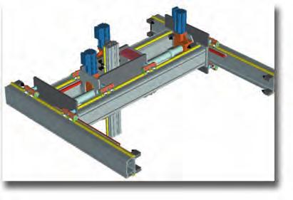
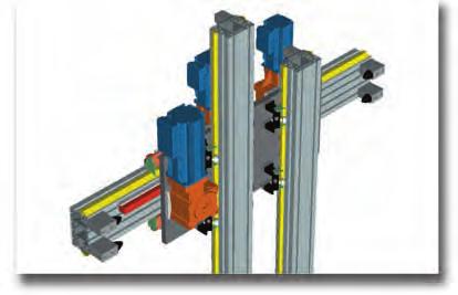

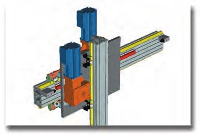
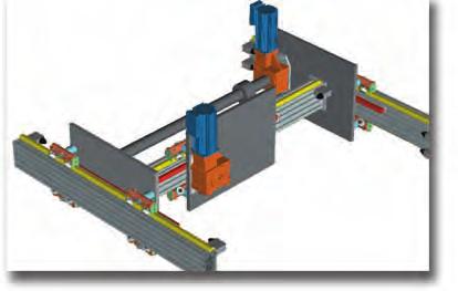
81 Standard assembly solutions Tecline 1 2 T T-73

82 Sizing template Our technical department is available to check sizing calculations. Please fill in the form with all the necessary data and send it to our technical dept., which will recommend the most suitable size according to the forces applied and precision required. AXIS DEFINITION Z-Axis X-Axis Y-Axis T-74
83 Technical data sheet Tecline For a correct design of the system, please fill the form below and send it to our technical dept. Date:... Filled in by... Company... Address... Phone...Fax... T ... SIZING TEMPATE required data optional data Assembly solutions (see page T-73) no... Z-Axis Y-Axis X-Axis Total length z y x [mm] Total working load including EOAT (add Z axis for Y and X axes) Pc Py Px [kg] Equipment weight on carriage (gearbox, cylinder, OPTIONA) Pay Pax [kg] Weight distributed on the beam (energy chain) Pdz Pdy Pdx [kg/m] Beam supports n n Max. projection (any cantilever, the largest) Sz Sy Sx [mm] Span (largest) dy dx [mm] Offset load s centre of gravity (X-axis) cx [mm] Offset load s centre of gravity (Y-axis) cy [mm] Offset load s centre of gravity (Z-axis) cz [mm] Additional force, if any F F F [N] +/- Possible distance between the carriages (see solutions 6-7 on page T-73) Dy Dx [mm] Transmission performance η Assembly: vertical= 90 - slope = 30, 45, 60 - horizontal = 0 α Stroke Qz Qy Qx [mm] Speed Vz Vy Vx [m/s] Acceleration Az Ay Ax [m/s 2 ] Cycle time Tz Ty Tx [s] Positioning accuracy +/- Repeatability +/- [mm] Work environment (temperature and cleanliness) Daily working cycles N Minimum service life requested [Km] Working cycle Working cycle example Remarks: T-75
84 Index Codice pag. Codice pag. Codice pag. Codice pag. Codice pag. Codice pag T T T T T T T T T T T-49 OGYCA T T T T-64 P28 T-46 P35 T-46 P55 T-46 P28.F T-46 P35.F T-46 P55.F T-46 P28.FX T-46 P35.FX T-46 P55.FX T-46 P28.FXX T-47 P35.FXX T-47 P55.FXX T T T T T T T T T T T T T T T T T T T T T T T T T T T T T T T T T T T T T T T T T T T T T T T T T T T T T T T T T T T T T T T T T T T T T T T T T T T T T T T T T T T T T T T T T T T T T T T T T T T T T T T T T T T T T T T T T T T T T T T T T T T T T T T T T T T T T T T T T T T T T T T T T T T T T T T T T T T T T T T T T T T T T T T T T T T-60 A30-00 T-61 A30-02 T-62 A30-10 T-61 A30-20 T-61 A30-30 T-62 A30-40 T-62 A30-54 T-61 A30-55 T-61 A30-56 T-61 A30-64 T-61 A30-65 T-61 A30-66 T-61 A30-76 T-61 A30-86 T-61 A32-40 T-65 A32-50 T-65 A32-60 T-65 A32-80 T-65 A32-91 T-66 A33-20 T-67 A33-26 T-67 A33-28 T-67 A40-50 T-63 B30-30 T-62 B30-40 T-62 B30-53 T-61 B30-54 T-61 B30-55 T-61 B30-56 T-61 B30-63 T-61 B30-64 T-61 B30-65 T-61 B30-66 T-61 B32-30 T-65 B32-40 T-65 B32-50 T-65 B32-60 T-65 C30-00 T-61 C30-02 T-62 E01-4 (90x90) T-67 E01-5 (90x180) T-67 E40-40 T-63 E40-60 T-63 MA1-5 T-67 PAR 1 T-4 PAR 1/05 T-20 PAR 10 T-18 PAR 10/6 T-38 PAR 10/8 T-40 PAR 2 T-6 PAR 2/1 T-22 PAR 3 T-8 PAR 3/1 T-24 PAR 4 T-10 PAR 4/1 T-26 PAR 5 T-12 PAR 5/2 T-28 PAR 6 T-14 PAR 6/2 T-30 PAR 6/4 T-32 PAR 8 T-16 PAR 8/3 T-34 PAR 8/6 T-36 PAS 1 T-5 PAS 1/05 T-21 PASM 10 T-19 PASM 10/6 T-39 PASM 10/8 T-41 PASM 2 T-7 PASM 2/1 T-23 PASM 3 T-9 PASM 3/1 T-25 PASM 4 T-11 PASM 4/1 T-27 PASM 5 T-13 PASM 5/2 T-29 PASM 6 T-15 PASM 6/2 T-31 PASM 6/4 T-33 PASM 8 T-17 PASM 8/3 T-35 PASM 8/6 T-37 T-76
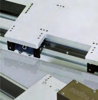
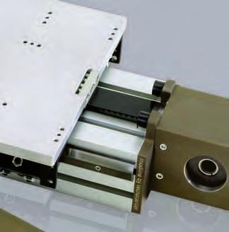
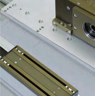
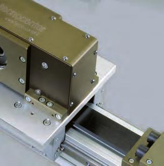

85 Modline
86


 without play transmissions")


87 Belt tension adjustment Drawing worked plate Drive head Roller slides inear guide rails Toothed belt Belt drive to Ω imit stop Reduction unitadapting plate Caged ball roller slides Modline linear modules are ready-to-use linear guide systems with high accuracy, speeds and load performances. Our experience in the fields of the automotive plants, painting, plate working, manufacturing machines and palletization systems has allowed us to widen our product range with the most advanced technical solutions. Our products stand out for their: high quality and competitive performances (profiles up to12m) without play transmissions achieved by high torque couplings beams with transversal stiffening ribs and preset for threads on profile ends accurate scaling and consequent reduced maintenance fast and accurate belt or without play screw drives the most complete range of accessories The Modline linear module strong points are: Acomplete series of linear units to build up 3 or more axis cartesian robots inear modules with linear guides suitable for parallel assembling Choice between strong steel linear guides with rollers or accurate caged ball roller slides and guides Choice between mobile carriage or fixed carriage and mobile profile Wide and complete solutions for control systems; programmable cards on request On request: assembling of E-chain cable carriers, reduction units, stiffening angle bars Drawing worked carriage plates Accessories and compatibility for pinion/rack drive unit integrated assembling


88 Contents INTRODUCTION Construction Features M-2 M MODUES WITH BET DRIVE MCR 65 with rollers MCH 65 with caged ball roller slides MCR 80 with rollers MCH 80 with caged ball roller slides MCR 105 with rollers MCH 105 with caged ball roller slides MCHH 105 with twin guide and caged ball roller slides M-3 M-4 M-5 M-6 M-7 M-8 M-9 MODUES WITH SCREW DRIVE MVR 80 with ball screw and rollers MVR with ball screw and rollers MVS MVH 105 with ball screw and rollers MVHH 105 with ball screw and caged ball roller slides TVH 180 with ball screw and caged ball roller slides TVS 170 with ball screw and caged ball roller slides TVS 220 with ball screw and caged ball roller slides M-10 M-11 M-12 M-13 M-14 M-15 M-16 This document replaces all previous editions. Due to the constant progress of our research we reserve the right to modify drawings or features without notice. No part of this catalogue may be reproduced without written permission of the copyright owner. All rights reserved. This catalogue has been accurately checked before publishing. However, we disclaim all responsibility in case of errors and omissions. T MODUES WITH BET DRIVE TCG 100 with shaped rollers M-17 TCH TCS 100 with caged ball roller slides M-18 TCRQ TCG 180 with rollers M-19 TCH TCS 180 with caged ball roller slides M-20 TCRQ 170 with rollers M-21 TCH TCS 170 with caged ball roller slides M-22 TCRQ 200 with rollers M-23 TCH TCS 200 with caged ball roller slides M-24 TCRQ 220 with rollers M-25 TCH TCS 220 with caged ball roller slides M-26 TCRQ TCRP 280 with rollers M-27 TCH TCS 280 with caged ball roller slides M-28 TCRP 360 with rollers M-29 TCH TCS 360 with caged ball roller slides M-30 TECRQ - TECH 170 (EASY) with roller or recirculating ball slides M-31 TECRR TECH 180 (EASY) with trapezoidal guides and roller slides M-32 K MODUES WITH BET DRIVE KCH with recirculating ball slides M-33 Edition Z MODUES WITH OMEGA BET DRIVE ZCG 60 with shaped rollers ZC 60 with caged ball roller slides ZCG 90 with shaped rollers ZCRR 90 with rollers ZC 90 with caged ball roller slides ZCY 180 with guide profile and shaped rollers M-34 M-35 M-36 M-37 M-38 M-39 M-80


89 Modline ZCRQ 100 with rollers ZC 100 with caged ball roller slides ZCRQ ZCERQ 170 with rollers ZC ZCE 170 with caged ball roller slides ZCRQ ZCERQ 220 with rollers ZC ZCE 220 with caged ball roller slides ZMCP ZMC 105 with pneumatic counter balance ZMCH 105 with pneumatic counter balance M-40 M-41 M-42 M-43 M-44 M-45 M-46 M-47 COMPONENTS Profile specifications M-48 ACCESSORIES AND APPICATIONS Drive Pulley Bores for Shrink Discs Adapter Flanges Connecting shafts for parallel modules Spare rollers - mounting brackets Accessories and screws Front insertable nuts and plates Threaded nuts and plates Alignment nuts Micro-switch supports - cams and cam-holders for micro-switches Special Options Special applications Anti-drop system - lock-pin device M-52 M-53 M-54 M-55 M-56 M-57 M-58 M-59 M-60 M-61 M-62 M-63 M TECHNICA INSTRUCTIONS Assembly specifications - ubrication Introduction - operation and control unit - Tightening specifications Assembly positions and load direction M-64 M-65 M-66 SIZING Standard assembly solutions Sizing template Sizing request form Index M-67 M-68 M-69 M-64 M-81
90 Construction Features Beams Obtained from Rollon extruded and anodised aluminium alloy profiles. Material features: Al Mg Si 0.5 hardened and tempered, F25 quality, Rm 245 N/mm2, tolerance as per EN and EN Profiles have been specially designed to achieve high stiffness and long lengths (up to 12 m), in order to obtain solid, lightweight structures, suitable for the construction of linear transfer machines. Plates Obtained from aluminium alloy rolled sections, tensile strength Rm 290 N/mm2, HB 77, high performance. On request we perform machining work on all standard plates (D code) and according to detailed customer drawings. V-shaped guide rails In hardened and ground high carbon steel (min. hardness 58 HRC). (Anti-oxidation coating upon request). Guide rails for caged ball roller slides S version: high performance, with cage, primary producers. version: high dynamics, medium loads. H version: standard performance. Roller slides Body in aluminium alloy G A SI 5 hardened and tempered according to UNI 3600 or Alloy 6082, rollers with double rows of angular contact ball bearings, backlash-free, long life lubrication: Ø 30, Ø 40, Ø 52, Ø 62 mm rollers. Adjustable tolerance between rollers and guide rails. Complete with new felt scrapers. Toothed drive and driven pulleys In C40 steel with coupling toothing on the polyurethane belt, backlash-free, with anti-oxidation treatment. Equipped with large, watertight bearings, capable of withstanding high work performance, due to the use of the multicarriage with durable, alternating backlash-free movements. Toothed belts In durable polyurethane, fitted with high-resistance reinforced with high tensile strength steel cords, which prevent the belt from lengthening over time. They are grease, oil and gasoline-proof and can work at temperatures from - 30 up to +80. The belt is fastened to the plate by means of a hooked support. The belt can be serviced without disassembling the equipment on the plate (standard versions). Shrink-discs, shafts and pulleys All models shown in the catalogue work with the standard conical shrink-disc drive system to lock the driving shaft and the driven shaft if present. Gearbox or shaft adapting plates are supplied upon request, as per drawing. Bumper Stops Important: the rubber stop pads provided with standard linear models are suitable and regarded as static limit switches. For special needs, such as stops if the drive breaks, please specify loads, dynamics, details and discuss the use of specific parts, accessories and devices (reinforced plates and attachments - shock absorbers, anti-drop devices, etc.) with our technical dept. Anodizing We supply all linear modules equipped with: natural, anodised aluminium alloy profiles (min. 11µ), driving heads, driven heads, carriages (MC series), counter plates, in dark bronze anodizing (min. 11µ). Anti-oxidation parts and coatings Modules are also available with anti-oxidation coating. Materials and coatings are selected according to the environment of use (food industry, marine environment, etc.). M-2
91 Series M Modules with belt drive Modline MCR 65 Registered model HARDENED GUIDE RAIS AND PROFIED ROERS Option: lighter version with pulley seats integrated within the profile Accessories: see page M-10 Ø(See page M-52 to M-53) 13 9 M M 65 61,7 3,3 30,85 36,5 Hole in the middle of profile used for setting the bearings Total length = Max. Stroke 87 Max. Stroke M SCREWS FOR BET TENSION Performances MCR 65 Max. stroke 5,830 [mm] Max. speed 4 [m/s] Max. acceleration 20 [m/s 2 ] Repeatability ± 0,1 [mm] No load torque - [mm] Suggested working load conditions Module M x [Nm] M y [Nm] M z [Nm] F x [N] F y [N] F z [N] MCR , ,000 The dynamic values shown do not refer to the max. theoretical load capacity. They include a safety coefficient for automated machinery. In case of peak forces acting together please ask the technical dept = Max belt strength Fy Data Belt 32AT05 Slide Rollers: 4 Ø 24-4 Ø 22 [mm] oad bearing profile 65x67 (see page M-48) Pulley Ø [mm] ead 160 [mm/rev] Weights Inertia of the pulley - [kgm 2 ] Belt weight 0.22 [kg/m] Carriage weight 1 [kg] Base module (stroke=0) M base =4.4 [kg] 1,000 mm profile q=5.4 [kg] To calculate the module weight use the following formula: M=M base +q stroke max /1,000 Stroke max [mm] M-3
92 MCH 65 Registered model GUIDE RAIS WITH CAGED BA RUNNER BOCKS Option: lighter version with pulley seats integrated within the profile Accessories: see page M-10 Ø(See page M-52 to M-53) 13 9 M ,3 61,7 30,85 36,5 Total length = Max. Stroke 87 Max. Stroke M SCREWS FOR BET TENSION Performances MCH 65 Max. stroke 7,830 [mm] Max. speed 3 [m/s] Max. acceleration 30 [m/s 2 ] Repeatability ± 0.1 [mm] No load torque - [mm] Suggested working load conditions Module M x [Nm] M y [Nm] M z [Nm] F x [N] F y [N] F z [N] F zb [N] MCH ,180 1,960 1,960 1,960 The dynamic values shown do not refer to the max. theoretical load capacity. They include a safety coefficient for automated machinery. In case of peak forces acting together please ask the technical dept = Max belt strength Fy Data Belt 32AT05 Slide 2 caged balls roller slides15 [mm] oad bearing profile 65x67 (see page M-48) Pulley Ø [mm] ead 160 [mm/rev] Weights Inertia of the pulley - [kgm 2 ] Belt weight 0.22 [kg/m] Carriage weight 1,1 [kg] Base module (stroke=0) M base =4.2 [kg] 1,000 mm profile q=6.2 [kg] To calculate the module weight use the following formula: M=M base +q stroke max /1,000 Stroke max [mm] M-4
93 MCR 80 Registered model HARDENED GUIDE RAIS AND PROFIED ROERS Option: version with additional belt protection (see page M-62) Option: short carriage version - code C Accessories: see page M-10 Modline Ø(See page M-52 to M-53) 18,5 M6 20 9,3 130 (short carriage: 65) Hole in the middle of profile used for setting the bearings Total length = Max. Stroke (short carriage =415 + Max. Stroke) 129 Max. Stroke (short carriage option: 150) M6 10 M short carriage option SCREWS FOR BET TENSION 78 Performances MCR 80 Max. stroke 5,700 [mm] Max. speed 5 [m/s] Max. acceleration 20 [m/s 2 ] Repeatability ± 0.1 [mm] No load torque 0.7 [Nm] Suggested working load conditions Module M x [Nm] M y [Nm] M z [Nm] F x [N] F y [N] F z [N] MCR , ,400 Suggested working load conditions short carriage option Module M x [Nm] M y [Nm] M z [Nm] F x [N] F y [N] F z [N] MCR 80...C , ,400 The dynamic values shown do not refer to the max. theoretical load capacity. They include a safety coefficient for automated machinery. In case of peak forces acting together please ask the technical dept = Max belt strength Fy Data Belt 32AT10 Slide Rollers: 4 Ø 24-4 Ø 22 [mm] oad bearing profile 80x80 (see page M-48) Pulley Ø [mm] ead 220 [mm/rev] Weights Inertia of the pulley [kgm 2 ] Belt weight 0.38 [kg/m] Carriage weight 2 [kg] Base module (stroke=0) M base =8 [kg] 1,000 mm profile q=7 [kg] To calculate the module weight use the following formula: M=M base +q stroke max /1,000 Stroke max [mm] M-5
94 MCH 80 Registered model GUIDE RAIS WITH CAGED BA RUNNER BOCKS Option: version with additional belt protection (see page M-62) Option: short carriage version - code C Accessories: see page M-10 Ø(See page M-52 to M-53) 18,5 M6 20 9,3 130 (short carriage: 65) 129 Total length = Max. Stroke (short carriage = Max. Stroke) Max. Stroke (short carriage option: 150) M short carriage option SCREWS FOR BET TENSION 78 Performances MCH 80 Max. stroke 5,700 [mm] Max. speed 5 [m/s] Max. acceleration 40 [m/s 2 ] Repeatability ± 0,1 [mm] No load torque 0.9 [Nm] Suggested working load conditions Module M x [Nm] M y [Nm] M z [Nm] F x [N] F y [N] F z [N] MCH ,150 2,900 2,900 Suggested working load conditions Module M x [Nm] M y [Nm] M z [Nm] F x [N] F y [N] F z [N] MCH 80...C ,150 1,450 1,450 The dynamic values shown do not refer to the max. theoretical load capacity. They include a safety coefficient for automated machinery. In case of peak forces acting together please ask the technical dept = Max belt strength Fy Data MCS80 - MCH80 Weights MCS80 - MCH80 Belt 32AT10 Inertia of the pulley [kgm 2 ] Slide 2 caged ball roller slides size 15* Belt weight 0.38 [kg/m] oad bearing profile 80x80 (see page M-48) Carriage weight 2.6 [kg] Pulley Ø [mm] Base module (stroke=0) M base =9 [kg] ead 220 [mm/rev] 1,000 mm profile q=8.2 [kg] * Short carriage option 1 pad To calculate the module weight use the following formula: M=M base +q stroke max /1,000 Stroke max [mm] M-6
95 MCR 105 Registered model HARDENED GUIDE RAIS AND PROFIED ROERS Option: version with additional belt protection (see page M-62) *Option: short carriage version - (code C) or long carriage (code ) Accessories: see page M-10 Modline Ø(See page M-52 to M-53) 24, (short carriage :90) 290 (long carriage ) M 70 52,5 105,9 63 Hole in the middle of profile used for setting the bearings 145 Total length = Max. Stroke (short carriage = Max. Stroke) Max. Stroke 17,5 300 (short carriage option: 200) 17,5 137 M6 6, M6 INSERTS FOR EACH SIDE THAT CAN BE ADJUSTED IN THE SOT SCREWS FOR BET TENSION Prestazioni Performances MCR 105 Max. stroke 10,100 [mm] Max. speed 5 [m/s] Max. acceleration 20 [m/s 2 ] Repeatability ± 0.1 [mm] No load torque 1.2 [Nm] 12 15, Suggested working load conditions Module M x [Nm] M y [Nm] M z [Nm] F x [N] F y [N] F z [N] MCR ,300 1,500 2,950 Suggested working load conditions short carriage option Module M x [Nm] M y [Nm] M z [Nm] F x [N] F y [N] F z [N] MCR C ,300 1,450 2,950 The dynamic values shown do not refer to the max. theoretical load capacity. They include a safety coefficient for automated machinery. In case of peak forces acting together please ask the technical dept = Max belt strength Fy Data Belt 40AT10 Slide Rollers: 4 Ø 37-4 Ø 35 [mm] oad bearing profile 105x105 (see page M-48) Pulley Ø [mm] ead 290 [mm/rev] Weights Inertia of the pulley [kgm 2 ] Belt weight 0.47 [kg/m] Carriage weight 3.5 [kg] Base module (stroke=0) M base =16.5 [kg] 1,000 mm profile q=13 [kg] To calculate the module weight use the following formula: M=M base +q stroke max /1,000 Stroke max [mm] M-7
96 MCH 105 Registered model GUIDE RAIS WITH CAGED BA RUNNER BOCKS Option: version with additional belt protection (see page M-62) *Option: short carriage version - (code C) Accessories: see page M-10 Ø(See page M-52 to M-53) 24, (short carriage:90) 52,5 105,9 63 Total length = Max. Stroke (short carriage = Max. Stroke) 145 Max. Stroke 17,5 300 (short carriage option: 200) 17,5 137 M , M6 INSERTS FOR EACH SIDE THAT CAN BE ADJUSTED IN THE SOT SCREWS FOR BET TENSION Performances MCH 105 Max. stroke 10,100 [mm] Max. speed 5 [m/s] Max. acceleration 50 [m/s 2 ] Repeatability ± 0.1 [mm] No load torque 1.5 [Nm] 12 15, Suggested working load conditions Module M x [Nm] M y [Nm] M z [Nm] F x [N] F y [N] F z [N] MCH ,300 6,030 6,030 Suggested working load conditions short carriage option Module M x [Nm] M y [Nm] M z [Nm] F x [N] F y [N] F z [N] MCH C ,300 3,018 3,018 The dynamic values shown do not refer to the max. theoretical load capacity. They include a safety coefficient for automated machinery. In case of peak forces acting together please ask the technical dept = Max belt strength Constuctive data Belt 40AT10 Weights Inertia of the pulley [kgm 2 ] Slide 2 caged ball roller slides size 20* Belt weight 0.47 [kg/m] oad bearing profile 105x105 (see page M-48) Carriage weight 4.5 [kg] Pulley Ø [mm] Base module (stroke=0) M base =18 [kg] ead 290 [mm/rev] 1,000 mm profile q=14.3 [kg] * Short carriage option 1 pad To calculate the module weight use the following formula: M=M base +q stroke max /1,000 Stroke max [mm] M-8
97 MCHH 105 Registered model TWIN GUIDE RAI AND CAGED BA ROER SIDES Accessories: see page M-10 Modline Ø(See page M-52 to M-53) 24, , ,5 137 M6 M ,5 105,9 63 Total length =615 + Max. Stroke 6,5 Max. Stroke 4 M6 INSERTS FOR EACH SIDE THAT CAN BE ADJUSTED IN THE SOT SCREWS FOR BET TENSION 15, Prestazioni Performances MCR MCHH Max. stroke 7,400 [mm] Max. speed 5 [m/s] Max. acceleration 50 [m/s 2 ] Repeatability ± 0.1 [mm] No load torque 2.2 [Nm] Suggested working load conditions Module M x [Nm] M y [Nm] M z [Nm] F x [N] F y [N] F z [N] MCHH ,300 7,200 6,210 The dynamic values shown do not refer to the max. theoretical load capacity. They include a safety coefficient for automated machinery. In case of peak forces acting together please ask the technical dept = Max belt strength Fy Data Belt 40AT10 Slide 4 caged ball roller slides size 15 oad bearing profile 105x105 (see page M-48) Pulley Ø [mm] ead 290 [mm/rev] Weights Inertia of the pulley [kgm 2 ] Belt weight 0.47 [kg/m] Carriage weight 4.5 [kg] Base module (stroke=0) M base =18 [kg] 1,000 mm di profile q=14 [kg] To calculate the module weight use the following formula: M=M base +q stroke max /1,000 Stroke max [mm] M-9
98 Modules with Screw Drive MVR 80 HARDENED GUIDES WITH CYINDRICA ROERS - BA SCREW M5 Ø 59 h7 Ø 10 h8 11,2 Total length =376 + Max. Stroke 120 Ø Max. Stroke Code M V R Screw length = Stroke V = Ball screw R = Rollers Max. Stroke [mm] Module total length [mm] Type of carriage Screw pitch Pedestal bearings N/D 5-10 Performances MVR 80 Max. stroke 2,500 [mm] Pitch [m/s] Max. speed Pitch 10 Pitch [m/s] [m/s] Max. acceleration 5 [m/s 2 ] Repeatability ± 0,05 [mm] Suggested working load conditions Module M x [Nm] M y [Nm] M z [Nm] F x [N] F y [N] F z [N] MVR *1, ,400 The values shown refer to maximum performance with each force acting individually. The dynamic data shown do not refer to the max. theoretical load capacity. They include a safety coefficient for automated machinery. (*) With a pitch of 5 mm SI 0 n [rpm] Safe Zone senza SI 3000 ength [mm] Max. stroke-speed limit over which some support bearings are required (SI) to avoid an excessive screw vibration. The working point marked inside the broken line is not recommended. Critical Speed Graph = Max belt strength Data Slide Rollers: 4 Ø24-4 Ø22 [mm] Beam 80x80 (see page M-48) Ø screw 16 [mm] ength of the screw 367+ max stroke [mm] Weights Inertia of the worm screw(m) [kgm 2 ] Carriage weight 2.5 c.a. [kg] Base module (stroke=0) M base = 5.5 approx. [kg] 1,000 mm profile q=8 approx. [kg] To calculate the module weight use the following formula: M=M base +q stroke max /1,000 Stroke max [mm] M-10
99 MVR 105 Registered model HARDENED GUIDES WITH CYINDRICA ROERS - BA SCREW Modline Ø16h Total length = Max. Stroke Ø95 M Max. Stroke 17, ,5 22 6,5 M6 12,5 Ø80h ,5 M 4 M6 INSERTS FOR EACH SIDE THAT CAN BE ADJUSTED IN THE SOT Code V = Ball screw R = Rollers Max. stroke [mm] Module total length [mm] Type of carriage Screw pitch Pedestal bearings Performances MVR 105 Max. stroke Pitch 5-10 = 4550 Pitch 25 = 5,150 [mm] Max. speed M V R N/D Pitch 5 [mm] 0.15 [m/s] Pitch 10 [mm] 0.30 [m/s] Pitch 25 [mm] 0.75 [m/s] Max. acceleration 5 [m/s 2 ] Repeatability ± 0.05 [mm] SI 8000 n [rpm] Critical Speed Graph unghezza ength [mm] [mm] Max. stroke-speed limit over which some support bearings are required (SI) to avoid an excessive screw vibration. The working point marked inside the broken line is not recommended. Suggested working load conditions Module M x [Nm] M y [Nm] M z [Nm] F x [N] F y [N] F z [N] MVR *2,000 1,500 2,950 The values shown refer to maximum performance with each force acting individually. The dynamic data shown do not refer to the max. theoretical load capacity. They include a safety coefficient for automated machinery. (*) With a pitch of 5 mm = Max belt strength Fy Data Slide Rollers: 4 Ø 37-4 Ø 35 [mm] Beam 105x105 (see page M-48) Ø screw 25 [mm] ength of the screw 440+ max stroke [mm] Weights Inertia of the worm screw(m) [kgm 2 ] Carriage weight 4 approx. [kg] Base module (stroke=0) M base =11 [kg] 1,000 mm profile q=17.2 approx. [kg] To calculate the module weight use the following formula: M=M base +q stroke max /1,000 Stroke max [mm] M-11
100 MVS 105 e MVH 105 GUIDE RAIS WITH CAGED BA RUNNER BOCKS - BA SCREW Max. Stroke M6 Ø80h Ø16h Total length = Max. Stroke Ø95 M6 45 6,5 12, ,5 4 M6 INSERTS FOR EACH SIDE THAT CAN BE ADJUSTED IN THE SOT Code M V V = Ball screw S = Caged ball roller slides H = Ball roller slides Max. stroke [mm] Module total length [mm] Type of carriage Screw pitch Pedestal bearings Performances MVS 105 MVH 105 Max. stroke Pitch 5-10 = 4,550 Pitch 25 = 5,150 [mm] N/D SI 8000 n [rpm] Critical Speed Graph Max. speed Pitch 5 [mm] [m/s] Pitch 10 [mm] [m/s] Pitch 25 [mm] [m/s] Max. acceleration 5 5 [m/s 2 ] Repeatability ± 0.05 ± 0.05 [mm] unghezza ength [mm] [mm] Max. stroke-speed limit over which some support bearings are required (SI) to avoid an excessive screw vibration. The working point marked inside the broken line is not recommended. Suggested working load conditions Module M x [Nm] M y [Nm] M z [Nm] F x [N] F y [N] F z [N] MVS ,000(*) 9,550 9,550 MVH ,000(*) 6,030 6,030 The values shown refer to maximum performance with each force acting individually. The dynamic data shown do not refer to the max. theoretical load capacity. They include a safety coefficient for automated machinery. (*) With a pitch of 5 mm = Max belt strength Fy Data Slide 2 caged ball roller slides size 20 Beam 105x105 (see page M-48) Ø screw 25 [mm] ength of the screw 440+ max stroke [mm] Weights Inertia of the worm screw(m) [kgm 2 ] Carriage weight 4 approx. [kg] Base module (stroke=0) M base =12 [kg] 1,000 mm profile q=17.2 approx. [kg] To calculate the module weight use the following formula: M=M base +q stroke max /1,000 Stroke max [mm] M-12
101 MVHH 105 GUIDE RAIS WITH CAGED BA RUNNER BOCKS - BA SCREW Registered model Modline Ø16h TOTA ength = Max Stroke Ø95 M Max STROKE 17, ,5 22 6,5 M6 12,5 Ø80h ,5 M 4 M6 INSERTS FOR EACH SIDE THAT CAN BE ADJUSTED IN THE SOT Critical Speed Graph Code M V HH 8000 V=ball screw H=ball roller slides Performances MVHH 105 Max Stroke Pitch 5-10 = 4550 Pitch 25 = 5150 [mm] Max Speed Max Stroke [mm] Module total length [mm] Type of carriage Screw pitch Pedestal bearings Pitch 5 [mm] 0,15 [m/s] Pitch 10 [mm] 0,30 [m/s] Pitch 25 [mm] 0,75 [m/s] Max acceleration 5 [m/s 2 ] Repeatability ± 0,05 [mm] N/D SI n [rpm] unghezza ength [mm] [mm] Max. stroke-speed limit over which some support bearings are required (SI) to avoid an excessive screw vibration. The working point marked inside the broken line is not recommended. Suggested working load conditions Module M x [Nm] M y [Nm] M z [Nm] F x [N] F y [N] F z [N] MVHH * The values shown refer to maximum performance with each force acting individually. The dynamic data shown do not refer to the max. theoretical load capacity. They include a safety coefficient for automated machinery. (*) With a pitch of 5 mm = Max belt strength Fy Data Slide 4 caged ball roller slides size 15 Beam 105x105 (see page M-48) Ø screw 25 [mm] ength of the screw 440+stroke max [mm] Weights Inertia of the worm 0,0003. screw(m) [kgm 2 ] Carriage weight 4 c.a. [kg] Base module (stroke=0) M base =13 [kg] 1,000 mm profile q=17,5 approx. [kg] To calculate the module weight use the following formula: M=M base +q stroke max /1,000 Stroke max [mm] M-13
102 TVH 180 GUIDE RAIS WITH CAGED BA RUNNER BOCKS - BA SCREW 52,5 18 Ø 16 h8 137,5 38,5 7,6 TOTA ength = x(Stroke/9) + Stroke 63 Stroke / 9 * Stroke / 9 * Ø80 h *valore indicativo Critical Speed Graph 77,8 n [rpm] 60,8 27, M unghezza ength [mm] [mm] Max. stroke-speed limit over which some support bearings are required (SI) to avoid an excessive screw vibration. The working point marked inside the broken line is not recommended. 137, Performances TVH 180 Max Stroke Pitch 5-10 = 4550 Pitch 25 = 5150 [mm] Max Speed Pitch 5 [mm] 0,15 [m/s] Pitch 10 [mm] 0,30 [m/s] Pitch 25 [mm] 0,75 [m/s] Suggested working load conditions Module M x [Nm] M y [Nm] M z [Nm] F x [N] F y [N] F z [N] TVH * The values shown refer to maximum performance with each force acting individually. The dynamic data shown do not refer to the max. theoretical load capacity. They include a safety coefficient for automated machinery. (*) With a pitch of 5 mm = Max belt strength Fy Data Slide 4 caged ball roller slides size 20 Beam E01-5 (see page M-49) Ø screw 25 [mm] Bellow heat-sealed, plastic Weights Inertia of the worm 0,0003. screw(m) [kgm 2 ] Carriage weight 7 [kg] Base module (stroke=0) M base = 20 [kg] 1,000 mm profile q= 20 [kg] To calculate the module weight use the following formula: M=M base +q stroke max /1,000 Stroke max [mm] M-14
103 TVS 170 GUIDE RAIS WITH CAGED BA RUNNER BOCKS - BA SCREW Modline 24,5 Ø 22 h M Total ength = x(Stroke/9) + Stroke Stroke / 9 * 480 Stroke / 9 * Ø 100 h *approx. value n [rpm] Max. stroke-speed limit over which some support bearings are required (SI) to avoid an excessive screw vibration. The working point marked inside the broken line is not recommended M8 unghezza ength [mm] [mm] Performances TVS 170 Max. stroke 4,000 [mm] Max. speed Pitch 5 [mm] 0.15 [m/s] Pitch 10 [mm] 0.30 [m/s] Pitch 20 [mm] 0.75 [m/s] Pitch 32 [mm] 1.00 [m/s] Suggested working load conditions Module M x [Nm] M y [Nm] M z [Nm] F x [N] F y [N] F z [N] TVS ,050 2,050 *6,000 11,950 11,950 The dynamic values shown do not refer to the max. theoretical load capacity. They include a safety coefficient for automated machinery. In case of peak forces acting together please ask the technical dept. (*) With a pitch of 10 mm = Max belt strength Fy Data Slide 4 caged ball roller slides size 20 Beam Statyca (see page M-50) Ø screw 32 [mm] Bellow heat-sealed, plastic Weights Inertia of the worm 0,0006. screw(m) [kgm 2 ] Carriage weight 11 [kg] Base module (stroke=0) M base = 36 [kg] 1,000 mm profile q= 28 [kg] To calculate the module weight use the following formula: M=M base +q stroke max /1,000 Stroke max [mm] M-15
104 TVS 220 GUIDE RAIS WITH CAGED BA RUNNER BOCKS - BA SCREW 42 7 Total length = x(Stroke/9) + Stroke Stroke / 9 * 480 Stroke / 9 * Ø 100 h ,5 Ø 22 h8 172 *approx. value n [rpm] unghezza ength [mm] [mm] Max. stroke-speed limit over which some support bearings are required (SI) to avoid an excessive screw vibration. The working point marked inside the broken line is not recommended. Performances TVS 220 Max. stroke 4,000 [mm] Max. speed Pitch 5 [mm] 0.15 [m/s] Pitch 10 [mm] 0.30 [m/s] Pitch 20 [mm] 0.75 [m/s] Pitch 32 [mm] 1.00 [m/s] M Suggested working load conditions Module M x [Nm] M y [Nm] M z [Nm] F x [N] F y [N] F z [N] TVS 220 1,300 3,200 3,200 *6,000 18,300 18,300 The dynamic values shown do not refer to the max. theoretical load capacity. They include a safety coefficient for automated machinery. In case of peak forces acting together please ask the technical dept. (*) With a pitch of 10 mm = Max belt strength Fy Data Slide 4 caged ball roller slides size 25 Beam ogyca (see page M-50) Ø screw 32 [mm] Bellow heat-sealed, plastic Weights Inertia of the worm screw(m) [kgm 2 ] Carriage weight 13 [kg] Base module (stroke=0) M base = 44 [kg] 1,000 mm profile q= 37 [kg] To calculate the module weight use the following formula: M=M base +q stroke max /1,000 Stroke max [mm] M-16
105 Series T modules with belt drive Modline TCG 100 HARDENED GUIDE RAIS AND CYINDRICA SHAPED ROERS Registered model 9, M 67 61,7 30,85 36,5 Ø(See page M-52 to M-53) Max. Stroke Total length = Max. Stroke MACHINING ON REQUEST Performances TCG 100 Max. stroke 5,490 [mm] Max. speed 5 [m/s] Max. acceleration 20 [m/s 2 ] Repeatability ± 0.1* [mm] oadless torque 2 [Nm] 70,5 Suggested working load conditions Module M x [Nm] M y [Nm] M z [Nm] F x [N] F y [N] F z [N] TCG ,100 1,700 1,200 The dynamic values shown do not refer to the max. theoretical load capacity. They include a safety coefficient for automated machinery. In case of peak forces acting together please ask the technical dept Assembly positions and load direction, see page M-66 = Max belt strength Fy Data Belt 25AT5 Slide 4 shaped rollers Ø35 [mm] oad bearing profile MA 1-4 (see page M-49) Pulley Ø [mm] inear displacement per revolution 160 [mm] Weights Inertia of the pulley - [kgm 2 ] Belt weight 0.21 [kg/m] Carriage weight 2.5 [kg] Base module (stroke=0) M base =6.4 [kg] 1,000 mm profile q=8.3 [kg] To calculate the module weight use the following formula: M=M base +q stroke max /1,000 Stroke max [mm] M-17
106 TCH 100 e TCS 100 GUIDE RAIS WITH CAGED BA ROER SIDES 9,8 61,7 30,85 36,5 Ø(See page M-52 to M-53) 130 Total length = Max. Stroke Max. Stroke MACHINING ON REQUEST Performances TCH 100 TCS 100 Max. stroke 5,400 5,400 [mm] Max. speed 5 5 [m/s] Max. acceleration [m/s 2 ] Repeatability ± 0.1 ± 0.1 [mm] oadless torque - - [Nm] Suggested working load conditions Module M x [Nm] M y [Nm] M z [Nm] F x [N] F y [N] F z [N] TCH ,180 4,100 4,100 TCS ,180 4,100 4,100 Fy The dynamic values shown do not refer to the max. theoretical load capacity. They include a safety coefficient for automated machinery. In case of peak forces acting together please ask the technical dept = Max belt strength Data Belt 25AT5 Sliding 4 caged ball roller slides size15 oad bearing profile MA 1-4 (see page M-49) Pulley Ø [mm] inear displacement per revolution 160 [mm] Weights Inertia of the pulley - [kgm 2 ] Belt weight 0.21 [kg/m] Carriage weight 2.6 [kg] Base module (stroke=0) M base =6.5 [kg] 1,000 mm profile q=9.2 [kg] To calculate the module weight use the following formula: M=M base +q stroke max /1,000 Stroke max [mm] M-18
107 TCRQ 180 e TCG 180 Registered model Ø(See page M-52 to M-53) WITH V-SHAPED GUIDE RAIS AND ROER SIDES OR SHAPED ROERS Accessories: see page M-10 Modline , (TCG: 280) Total length = Max. Stroke (TCG = Max. Stroke) Max. Stroke 380 (TCG: 330) M Coupling with ZC module assembled orthogonally: if pairing with ZCR - ZC modules (see pages M-34 to M-47) is required, the plate will be supplied duly machined. Indicate the side of assembly. MACHINING ON REQUEST ,5 Performances TCRQ 180 TCG 180 Max. stroke 7,480 7,540 [mm] Max. speed 5 5 [m/s] Max. acceleration [m/s 2 ] Repeatability ± 0.1 ± 0.1 [mm] oadless torque [Nm] TCR Suggested working load conditions Module M x [Nm] M y [Nm] M z [Nm] F x [N] F y [N] F z [N] TCG 180 TCRQ ,300 7,320 7,320 TCG ,300 3,400 1,800 The dynamic values shown do not refer to the max. theoretical load capacity. They include a safety coefficient for automated machinery. In case of peak forces acting together please ask the technical dept Assembly positions and load direction, see page M-66 = Max belt strength Fy Data TCRQ 180 TCG 180 Weights TCRQ 180 TCG 180 Belt 40AT10 Inertia of the pulley [kgm 2 ] Slide 4 roller slides with 2 rollers Belt weight 0.55 [kg/m] 4 rollers Ø 52, guide Ø16 Carriage weight [kg] oad bearing profile E01-5 (see page M-49) Base module (stroke=0) M Pulley Ø [mm] base = [kg] inear displacement per rev. 290 [mm] 1,000 mm profile q=21 q=16.8 [kg] To calculate the module weight use the following formula: M=M base +q stroke max /1,000 Stroke max [mm] M-19
108 TCH 180 e TCS 180 GUIDE RAIS WITH CAGED BA ROER SIDES Registered Model Accessories: see page M-10 Ø(See page M-52 to M-53) , Total length = Max. Stroke Max. Stroke ,5 105 Coupling with ZC module assembled orthogonally: if pairing with ZCR - ZC modules (see pages M-34 to M-47) is required, the plate will be supplied duly machined. Indicate the side of assembly. 20 MACHINING ON REQUEST Performances TCH 180 TCS 180 Max. stroke 7,340 7,340 [mm] Max. speed 5 5 [m/s] Max. acceleration [m/s 2 ] Repeatability ± 0.1 ± 0.1 [mm] oadless torque [Nm] Suggested working load conditions Module M x [Nm] M y [Nm] M z [Nm] F x [N] F y [N] F z [N] TCH ,300 9,200 9,200 TCS ,350 1,350 3,300 10,950 10,950 Fy The dynamic values shown do not refer to the max. theoretical load capacity. They include a safety coefficient for automated machinery. In case of peak forces acting together please ask the technical dept = Max belt strength Data TCH TCS 180 Belt 40AT10 Slide 4 caged ball slides size 20 oad bearing profile E01-5 (see page M-49) Pulley Ø [mm] inear displacement per rev. 290 [mm] Weights TCH TCS 180 Inertia of the pulley [kgm 2 ] Belt weight 0.55 [kg/m] Carriage weight 6 [kg] Base module (stroke=0) M base =23.6 [kg] 1,000 mm profile q=19 [kg] To calculate the module weight use the following formula: M=M base +q stroke max /1,000 Stroke max [mm] M-20
109 TCRQ 170 Registered model V-SHAPED GUIDE RAIS WITH ROER SIDES Accessories: see page M-10 Modline Ø(See page M-52 to M-53) Total length = Max. Stroke Max. Stroke M 120 Coupling with ZC module assembled orthogonally: if pairing with ZCR - ZC modules (see pages M-34 to M-47) is required, the plate will be supplied duly machined. Indicate the side of assembly. MACHINING ON REQUEST 400 Performances TCRQ 170 Max. stroke 5,480 [mm] Max. speed 7 [m/s] Max. acceleration 20 [m/s 2 ] Repeatability ± 0.1 [mm] oadless torque 4.2 [Nm] Suggested working load conditions Module M x [Nm] M y [Nm] M z [Nm] F x [N] F y [N] F z [N] TCRQ ,202 1,202 4,000 7,070 7,070 The dynamic values shown do not refer to the max. theoretical load capacity. They include a safety coefficient for automated machinery. In case of peak forces acting together please ask the technical dept Assembly positions and load direction, see page M-66 = Max belt strength Fy Data Belt 50AT10 Slides 4 slides 2 rollers Ø40 [mm] oad bearing profile Statyca (see page M-50) Pulley Ø [mm] inear displacement per rev. 300 [mm] Weights Inertia of the pulley [kgm 2 ] Belt weight 0.68 [kg/m] Carriage weight 14.6 [kg] Base module (stroke=0) M base =44.6 [kg] 1,000 mm profile q=25 [kg] To calculate the module weight use the following formula: M=M base +q stroke max /1,000 Stroke max [mm] M-21
110 TCH 170 e TCS 170 GUIDE RAIS WITH CAGED BA ROER SIDES Registered Model Accessories: see page M-10 Ø(See page M-52 to M-53) Total length = Max. Stroke Max. Stroke Coupling with ZC module assembled orthogonally: if pairing with ZCR - ZC modules (see pages M-34 to M-47) is required, the plate will be supplied duly machined. Indicate the side of assembly. MACHINING ON REQUEST Performances TCH 170 TCS 170 Max. stroke 5,480 5,480 [mm] Max. speed 5 5 [m/s] Max. acceleration [m/s 2 ] Repeatability ± 0.1 ± 0.1 [mm] oadless torque [Nm] Suggested working load conditions Module M x [Nm] M y [Nm] M z [Nm] F x [N] F y [N] F z [N] TCH ,430 1,430 4,000 9,400 9,400 TCS ,050 2,050 4,000 11,950 11,950 Fy The dynamic values shown do not refer to the max. theoretical load capacity. They include a safety coefficient for automated machinery. In case of peak forces acting together please ask the technical dept = Max belt strength Data TCH TCS 170 Belt 50AT10 Slide 4 caged ball slides size 20 oad bearing profile Statyca (see page M-50) Pulley Ø [mm] inear displacement per rev. 300 [mm] Weights TCH TCS 170 Inertia of the pulley [kgm 2 ] Belt weight 0.68 [kg/m] Carriage weight 8.6 [kg] Base module (stroke=0) M base =38 [kg] 1,000 mm profile q=23 [kg] To calculate the module weight use the following formula: M=M base +q stroke max /1,000 Stroke max [mm] M-22
111 TCRQ 200 Registered model V-SHAPED GUIDE RAIS WITH ROER SIDES Accessories: see page M-10 Modline Ø(See page M-52 to M-53) * Total length = Max. Stroke Max. Stroke M 120 Coupling with ZC module assembled orthogonally: if pairing with ZCR - ZC modules (see pages M-34 to M-47) is required, the plate will be supplied duly machined. Indicate the side of assembly. 400 MACHINING ON REQUEST * : Please specify the roller orientation according to the barycentre of the applied load. Values corresponding to the most favourable load position. Performances TCRQ 200 Max. stroke 8,480 [mm] Max. speed 5 [m/s] Max. acceleration 20 [m/s 2 ] Repeatability ± 0.1 [mm] oadless torque 4.2 [Nm] Suggested working load conditions Module M x [Nm] M y [Nm] M z [Nm] F x [N] F y [N] F z [N] TCRQ 200 1,300(*) 1,600(*) 1,300 4,000 7,620 12,500 (*) The dynamic values shown do not refer to the max. theoretical load capacity. They include a safety coefficient for automated machinery. In case of peak forces acting together please ask the technical dept = Max belt strength 20 Fy 155 Assembly positions and load direction, see page M-66 Data Belt 50AT10 Slide 4 slides 3 roll. Ø40 [mm] oad bearing profile Valyda (see page M-50) Pulley Ø [mm] inear displacement per rev. 300 [mm] Weights Inertia of the pulley [kgm 2 ] Belt weight 0.68 [kg/m] Carriage weight 15 [kg] Base module (stroke=0) M base =52 [kg] 1,000 mm profile q=30 [kg] To calculate the module weight use the following formula: M=M base +q stroke max /1,000 Stroke max [mm] M-23
112 TCH 200 e TCS 200 GUIDE RAIS WITH CAGED BA ROER SIDES Registered model Accessories: see page M-10 Ø(See page M-52 to M-53) Total length = Max. Stroke Max. Stroke Coupling with ZC module assembled orthogonally: if pairing with ZCR - ZC modules (see pages M-34 to M-47) is required, the plate will be supplied duly machined. Indicate the side of assembly. 220 MACHINING ON REQUEST Performances TCH 200 TCS 200 Max. stroke 8,480 8,480 [mm] Max. speed 5 5 [m/s] Max. acceleration [m/s 2 ] Repeatability ± 0.1 ± 0.1 [mm] oadless torque [Nm] Suggested working load conditions Module M x [Nm] M y [Nm] M z [Nm] F x [N] F y [N] F z [N] TCH ,430 1,430 4,000 9,400 9,400 TCS ,050 2,050 4,000 13,950 13,950 Fy The dynamic values shown do not refer to the max. theoretical load capacity. They include a safety coefficient for automated machinery. In case of peak forces acting together please ask the technical dept = Max belt strength Data TCH TCS 200 Belt 50AT10 Slide 4 caged ball slides size 20 oad bearing profile Valyda (see page M-50) Pulley Ø [mm] inear displacement per rev. 300 [mm] Weights TCH TCS 200 Inertia of the pulley [kgm 2 ] Belt weight 0.68 [kg/m] Carriage weight 8,8 [kg] Base module (stroke=0) M base =42 [kg] 1,000 mm profile q=27.5 [kg] To calculate the module weight use the following formula: M=M base +q stroke max /1,000 Stroke max [mm] M-24
113 TCRQ 220 V-SHAPED GUIDE RAIS WITH ROER SIDES Registered model Accessories: see page M-10 Modline Ø(See page M-52 to M-53) * 340 Total length = Max. Stroke Max. Stroke M 145 Coupling with ZC module assembled orthogonally: if pairing with ZCR - ZC modules (see pages M-34 to M-47) is required, the plate will be supplied duly machined. Indicate the side of assembly. 400 MACHINING ON REQUEST * : Please specify the roller orientation according to the barycentre of the applied load. Values corresponding to the most favourable load position Performances TCRQ 220 Max. stroke 11,480 [mm] Max. speed 5 [m/s] Max. acceleration 20 [m/s 2 ] Repeatability ± 0.1 [mm] oadless torque 5.8 [Nm] Suggested working load conditions Module M x [Nm] M y [Nm] M z [Nm] F x [N] F y [N] F z [N] TCRQ220 1,400(*) 1,600(*) 1,300 6,000 7,620 12,500(*) The dynamic values shown do not refer to the max. theoretical load capacity. They include a safety coefficient for automated machinery. In case of peak forces acting together please ask the technical dept Assembly positions and load direction, see page M-66 = Max belt strength Fy Data Belt 75AT10 Slide 4 slides 3 roll. Ø 40 [mm] oad bearing profile ogyca (see page M-50) Pulley Ø [mm] inear displacement per rev. 300 [mm] Weights Inertia of the pulley 0,0082 [kgm 2 ] Belt weight 1,02 [kg/m] Carriage weight 16 [kg] Base module (stroke=0) M base =54.6 [kg] 1,000 mm profile q= 33.7 [kg] To calculate the module weight use the following formula: M=M base +q stroke max /1,000 Stroke max [mm] M-25
114 TCH TCS 220 GUIDE RAIS WITH CAGED BA ROER SIDES Registered model Accessories: see page M-10 Ø(See page M-52 to M-53) Total length = Max. Stroke Max. Stroke MACHINING ON REQUEST Performances TCH 220 TCS 220 Max. stroke 11,480 11,480 [mm] Max. speed 5 5 [m/s] Max. acceleration [m/s 2 ] Repeatability ± 0.1 ± 0.1 [mm] oadless torque [Nm] Suggested working load conditions Module M x [Nm] M y [Nm] M z [Nm] F x [N] F y [N] F z [N] TCH ,200 2,200 6,000 13,000 13,000 TCS 220 1,300 3,200 3,200 6,000 18,300 18,300 Fy The dynamic values shown do not refer to the max. theoretical load capacity. They include a safety coefficient for automated machinery. In case of peak forces acting together please ask the technical dept = Max belt strength Data TCH TCS 220 Belt 75AT10 Slide 4 caged ball slides size 25 oad bearing profile ogyca (see page M-50) Pulley Ø [mm] inear displacement per rev. 300 [mm] Weights TCH TCS 220 Inertia of the pulley [kgm 2 ] Belt weight 1.02 [kg/m] Carriage weight 9.5 [kg] Base module (stroke=0) M base =47.4 [kg] 1,000 mm profile q=33 [kg] To calculate the module weight use the following formula: M=M base +q stroke max /1,000 Stroke max [mm] M-26
115 TCRQ 280 (TCRP 280) V-SHAPED GUIDE RAIS WITH ROER SIDES Registered model * RP= Heavy guide rails and roller slides - Ø52 Accessories: see page M-10 Modline Ø(See page M-52 to M-53) 510 (520) Total length = 1,125 + Max. Stroke (1215) Max. Stroke 650 (680) M 145 Coupling with ZC module assembled orthogonally: if pairing with ZCR - ZC modules (see pages M-34 to M-47) is required, the plate will be supplied duly machined. Indicate the side of assembly. MACHINING ON REQUEST : Please specify the roller orientation according to the barycentre of the applied load. * Values corresponding to the most favourable load position. Performances TCRQ 280 (TCRP280) Max. stroke 11,315 11,175 [mm] Max. speed 7 5 [m/s] Max. acceleration [m/s 2 ] Repeatability ± 0.1 ± 0.1 [mm] oadless torque [Nm] Suggested working load conditions Module M x [Nm] M y [Nm] M z [Nm] F x [N] F y [N] F z [N] TCRQ 280 1,950(*) 3,100(*) 1,950 6,000 7,620 13,500(*) TCRP 280 3,100 4,150 4,150 6,000 20,100 20,100 The dynamic values shown do not refer to the max. theoretical load capacity. They include a safety coefficient for automated machinery. In case of peak forces acting together please ask the technical dept Versions with a 100 mm belt are also available. (TCRE/TCREP) 450 = Max belt strength 25 Fy 215 Assembly positions and load direction, see page M-66 Data TCRQ 280 (TCRP 280) Weights TCRQ 280 (TCRP 280) Belt 75 AT 10 Inertia of the pulley [kgm 2 ] Slide 4 slides 3 rollers Ø40 4 slides 4 rollers Ø52 [mm] Belt weight 1.02 [kg/m] oad bearing profile Pratyca (see page M-51) Carriage weight [kg] Pulley Ø [mm] Base module M base =87 M base =122 [kg] inear displacement per rev ,000 mm profile q=48 q=56 [kg] [mm] To calculate the module weight use the following formula: M=M base +q stroke max /1,000 Stroke max [mm] M-27
116 TCH TCS 280 GUIDE RAIS WITH CAGED BA ROER SIDES Registered model Accessories: see page M Ø(See page M-52 to M-53) 360 Total length = Max. Stroke Max. Stroke Coupling with ZC module assembled orthogonally: if pairing with ZCR - ZC modules (see pages M-34 to M-47) is required, the plate will be supplied duly machined. Indicate the side of assembly MACHINING ON REQUEST * Versions with a 100 mm belt are also available. (TCSE 280) Performances TCH 280 TCS Max. stroke 11,480 11,485 [mm] Max. speed 5 5 [m/s] Max. acceleration [m/s 2 ] Repeatability ± 0.1 ± 0.1 [mm] oadless torque [Nm] Suggested working load conditions Module M x [Nm] M y [Nm] M z [Nm] F x [N] F y [N] F z [N] TCH 280 1,450 2,200 2,200 6,000 13,500 13,500 TCS 280 1,950 3,200 3,200 6,000 20,300 20,300 Fy The dynamic values shown do not refer to the max. theoretical load capacity. They include a safety coefficient for automated machinery. In case of peak forces acting together please ask the technical dept = Max belt strength Data TCH TCS 280 Belt 75 AT 10 Slide 4 caged ball slides size 25 oad bearing profile Pratyca (see page M-51) Pulley Ø [mm] inear displacement per rev. 300 [mm] Weights TCH TCS 280 Inertia of the pulley [kgm 2 ] Belt weight 1.02 [kg/m] Carriage weight 18 [kg] Base module (stroke=0) M base =69 [kg] 1,000 mm profile q= 47 [kg] To calculate the module weight use the following formula: M=M base +q stroke max /1,000 Stroke max [mm] M-28
117 TCRP 360 Registered model V-SHAPED GUIDE RAIS WITH ROER SIDES RP= Heavy guide rails and roller slides - Ø52 Accessories: see page M-10 Modline Ø(See page M-52 to M-53) 530 Total length = 1,208 + Max. Stroke Max. Stroke M * MACHINING ON REQUEST Coupling with ZC module assembled orthogonally: if pairing with ZCR - ZC modules (see pages 42 to 53) is required, the plate will be supplied duly machined. Indicate the side of assembly. * Versions with a 150 mm belt are also available. (TCRPE360) Performances TCRP 360 Max. stroke Max. speed Max. acceleration Repeatability oadless torque 11, ± [mm] [m/s] [m/s 2 ] [mm] [Nm] SCREWS FOR BET TENSION Suggested working load conditions Module M x [Nm] M y [Nm] M z [Nm] F x [N] F y [N] F z [N] TCRP 360 4,900 5,300 5,300 8,000 25,400 25,400 The dynamic values shown do not refer to the max. theoretical load capacity. They include a safety coefficient for automated machinery. In case of peak forces acting together please ask the technical dept 600 = Max belt strength Fy Assembly positions and load direction, see page M-66 Data Belt 100 AT 10 Slide 4 slides 4 rollers Ø52 [mm] oad bearing profile Solyda (see page M-51) Pulley Ø [mm] inear displacement per rev. 300 [mm] Weights Inertia of the pulley [kgm 2 ] Belt weight 1.02 [kg/m] Carriage weight 55 [kg] Base module (stroke=0) M base =137 [kg] 1,000 mm profile q=75 [kg] To calculate the module weight use the following formula: M=M base +q stroke max /1,000 Stroke max [mm] M-29
118 TCH TCS 360 Registered model GUIDE RAIS WITH CAGED BA ROER SIDES Accessories: see page M Ø(See page M-52 to M-53) 484 Total length = 1,176 + Max. Stroke 30 Max. Stroke , MACHINING ON REQUEST SCREWS FOR BET TENSION * Versions with a 150 mm belt are also available. (TCSE360) Performances TCH 360 TCS 360 Max. stroke 11,480 11,485 [mm] Max. speed 5 5 [m/s] Max. acceleration [m/s 2 ] Repeatability ± 0.1 ± 0.1 [mm] oadless torque [Nm] 262 Suggested working load conditions Module M x [Nm] M y [Nm] M z [Nm] F x [N] F y [N] F z [N] TCH 360 2,600 3,710 3,710 8,000 19,050 19,050 TCS 360 4,000 5,500 5,500 8,000 28,600 28,600 The dynamic values shown do not refer to the max. theoretical load capacity. They include a safety coefficient for automated machinery. In case of peak forces acting together please ask the technical dept = Max belt strength Fy Data TCH TCS 360 Belt 100 AT 10 Slide 4 caged ball roller slides 30 oad bearing profile Solyda (see page M-51) Pulley Ø [mm] inear displacement per rev. 300 [mm] Weights TCH TCS 360 Inertia of the pulley [kgm 2 ] Belt weight 1.02 [kg/m] Carriage weight 28 [kg] Base module (stroke=0) M base =105 [kg] 1,000 mm profile q= 70 [kg] To calculate the module weight use the following formula: M=M base +q stroke max /1,000 Stroke max [mm] M-30
119 TECRQ - TECH 170 (EASY) TRAPEZOIDA GUIDES AND ROER SIDES OR RECIRCUATING BA SIDES Modline Total lenght = Max Stroke Max Stroke M M Recirculating ball slides 350 Coupling with ZC type module assembled at right angles: in the case of ZCR-ZC unit assembly (see from pg. M-34 to M-47 of the Modline manual) the plate will be provided with notches and holes. Indicate the assembly side. 20 Performances TECR 170 TECH 170 Max stroke [mm] Max speed 5 4 [m/s] Max acceleration [m/s 2 ] Repositioning accuracy ± 0.1 ± 0.1 [mm] oadless torque [Nm] Roller slides Suggested working load conditions Module M x [Nm] M y [Nm] M z [Nm] F x [N] F y [N] F z [N] TECR TECH The dynamic values indicated do not correspond to maximum theoretical load capacities. They already take safety factors into account which are suitable for machinery in the automation sector. In the event of combined stress consult the technical support service. = Max belt strenght Fy Constructive data TECR TECH 170 Belt 50 AT 10 Sliding (TECR170) 4 roller slides [mm] Sliding (TECH 170) 4 ball slides size 20 [mm] Profile Statyca (see page M-50) Pulley Ø 95,49 [mm] inear displacement per revolution 300 [mm] Weight TECH TECR 170 Inertia of the pulley 0,0053 [kgm 2 ] Belt weight 0,68 [kg/m] Carriage weight 8,6 [kg] Base module (corsa=0) M base = 38 [kg] mm profile q=23 [kg] To calculate the module weight use the following formula: M=M base +q Stroke max /1.000 Stroke max [mm] M-31
120 TECRR TECH 180 (EASY) Patent pending TRAPEZOIDA GUIDES AND ROER SIDES OR RECIRCUATING BA SIDES , M8 Total lenght = Max Stroke Max Stroke Recirculating ball slides Performances TECRR 180 Max stroke [mm] Max speed 5 [m/s] Max acceleration 20 [m/s 2 ] Repositioning accuracy ± 0,1* [mm] oadless torque 4,2 [Nm] 350 Roller slides ,5 Suggested working load conditions Module M x [Nm] M y [Nm] M z [Nm] F x [N] F y [N] F z [N] TECRR The dynamic values indicated do not correspond to maximum theoretical load capacities. They already take safety factors into account which are suitable for machinery in the automation sector. In the event of combined stress consult the technical support service. = Max belt strenght Fy Constructive data Belt 40AT10 Sliding 4 slides 4 rollers Ø30 [mm] Profile 180x90 Pulley Ø 92,31 [mm] inear displacement per revolution 290 [mm] Weight Inertia of the pulley 0,0037 [kgm 2 ] Belt weight 0,55 [kg/m] Carriage weight 13 [kg] Base module (stroke=0) M base =33 [kg] mm profile q=16 [kg] To calculate the module weight use the following formula: M=M base +q Stroke max /1.000 Stroke max [mm] M-32
121 SERIE K MODUES GEAR MOTOR ASSEMBY POSSIBE FROM EACH SIDE Modline KCH 100/150/200 GEAR MOTOR ASSEMBY POSSIBE FROM EACH SIDE M8 M Total lenght = Max Stroke 2,5 Max Stroke 400 2, M Shrink disc interface *Pulley hole (motor side = pipe side) Ø14 wrench 5x5 * [mm] Interfaces with conical shrink discs and/or pulleys in steel are available on request. The heads are equal Belt adjustment under load (does not require dismantling of equipment) Sizes available Performances KCH /... Max stroke [mm] Max speed 4 [m/s] Max acceleration 50 [m/s 2 ] Repositioning accuracy ± 0,1* [mm] oadless torque - [Nm] *on request ± 0, Suggested working load conditions Modulo M x [Nm] M y [Nm] M z [Nm] F x [N] F y [N] F z [N] KCH/ The dynamic values indicated do not correspond to maximum theoretical load capacities. They already take safety factors into account which are suitable for machinery in the automation sector. In the event of combined stress consult the technical support service. Choice of beam depending on availability between supports. 200 Fy = Max belt strenght Constructive data Belt 32AT10 Sliding 4 ball slides [mm] Profile 50 x... Pulley Ø 70,03 [mm] inear displacement per revolution 220 [mm] Colour natural anodisation Weights Inertia of the pulley - [kgm 2 ] Belt weight 0,38 [kg/m] Carriage weight 2,2 [kg] Base module (stroke=0) M base = 9 [kg] mm profile q=3 + profile [kg] To calculate the module weight use the following formula: M=M base +q Stroke max /1.000 Stroke max [mm] M-33
122 ZCG 60 OMEGA BET DRIVE HARDENED GUIDE RAIS AND SHAPED ROERS Accessories: see page M-10 Ø(See page M-52 to M-53) , Max. Stroke Total length = Max. Stroke SCREWS FOR BET TENSION 60x90 profile available IMPORTANT: when pairing ZC... modules with TC... modules, please check the required Z axis stroke, as this could be limited by the size of the module plates sizes. Performances ZCG 60 Max. stroke 5,470 [mm] Max. speed 4 [m/s] Max. acceration 20 [m/s 2 ] Repeatability ± 0.1 [mm] Suggested working load conditions Module M x [Nm] M y [Nm] M z [Nm] F x [N] F y [N] F z [N] ZCG ,000 2,100 1,500 Fy = Max belt strength The dynamic values shown do not refer to the max. theoretical load capacity. They include a safety coefficient for automated machinery. In case of peak forces acting together please ask the technical dept Assembly positions and load direction, see page M-66 Data Belt 32AT10 Slide 4 shaped roller slides Ø 42 [mm] oad bearing profile F01-1 (see page M-48) Pulley Ø [mm] inear displacement per rev. 220 [mm] Weights Inertia of the pulley [kgm 2 ] Belt weight 0.19 [kg/m] Carriage weight 10 [kg] Base module (stroke=0) M base =14 [kg] 1,000 mm profile q=6 [kg] To calculate the module weight use the following formula: M=M base +q stroke max /1,000 Stroke max [mm] M-34
123 ZC 60 OMEGA BET DRIVE GUIDE RAIS WITH CAGED BA ROER SIDES Accessories: see page M-10 Modline Ø(See page M-52 to M-53) , M Total length = Max. Stroke SCREWS FOR BET TENSION 55 Max. Stroke x90 profile available IMPORTANT: when pairing ZC... modules with TC... modules, please check the required Z axis stroke, as this could be limited by the size of the module plates sizes. Performances ZC 60 Max. stroke 5,470 [mm] Max. speed 4 [m/s] Max. acceleration 40 [m/s 2 ] Repeatability ± 0.1 [mm] Fy = Max belt strength Suggested working load conditions Module M x [Nm] M y [Nm] M z [Nm] F x [N] F y [N] F z [N] ZC ,000 4,180 3,740 The dynamic values shown do not refer to the max. theoretical load capacity. They include a safety coefficient for automated machinery. In case of peak forces acting together please ask the technical dept Data Belt 32AT10 Slide 4 caged ball roller slides 15 oad bearing profile F01-1 (see page M-48) Pulley Ø [mm] inear displacement per rev. 220 [mm] Weights Inertia of the pulley [kgm 2 ] Belt weight 0.19 [kg/m] Carriage weight 11 [kg] Base module (stroke=0) M base =16 [kg] 1,000 mm profile q=7.2 [kg] To calculate the module weight use the following formula: M=M base +q stroke max /1,000 Stroke max [mm] M-35
124 ZCG 90 OMEGA BET DRIVE HARDENED GUIDE RAIS AND SHAPED ROERS Accessories: see page M-10 Ø(See page M-52 to M-53) , , SCREWS FOR BET TENSION Total length = Max. Stroke 55 Max. Stroke x180 profile available IMPORTANT: when pairing ZC... modules with TC... modules, please check the required Z axis stroke, as this could be limited by the size of the module plates sizes. Performances ZCG 90 Max. stroke 5,450 [mm] Max. speed 4 [m/s] Max. acceleration 15 [m/s 2 ] Repeatability ± 0.1 [mm] Suggested working load conditions Module M x [Nm] M y [Nm] M z [Nm] F x [N] F y [N] F z [N] ZCG ,000 3,400 1,800 Fy = Max belt strength The dynamic values shown do not refer to the max. theoretical load capacity. They include a safety coefficient for automated machinery. In case of peak forces acting together please ask the technical dept Assembly positions and load direction, see page M-66 Data Belt 32AT10 Slide 4 shap. r. Ø52 - guide Ø16 oad bearing profile E01-4 (see page M-48) Pulley Ø [mm] inear displacement per rev. 220 [mm] Weights Inertia of the pulley [kgm 2 ] Belt weight 0.19 [kg/m] Carriage weight 10.5 [kg] Base module (stroke=0) M base =16 [kg] mm profile q=8.5 [kg] To calculate the module weight use the following formula: M=M base +q stroke max /1,000 Stroke max [mm] M-36
125 ZCRR 90 OMEGA BET DRIVE HARDENED GUIDE RAIS AND TITING ROER SIDES Accessories: see page M-10 Modline Ø(See page M-52 to M-53) , Total length = Max. Stroke SCREWS FOR BET TENSION 55 CORSAmax x180 profile available M IMPORTANT: when pairing ZC... modules with TC... modules, please check the required Z axis stroke, as this could be limited by the size of the module plates sizes. Performances ZCRR 90 Max. stroke 5,450 [mm] Max. speed 4 [m/s] Max. acceleration 25 [m/s 2 ] Repeatability ± 0.1 [mm] Suggested working load conditions Module M x [Nm] M y [Nm] M z [Nm] F x [N] F y [N] F z [N] ZCRR ,000 1,000 2,000 6,700 6,700 Fy = Max belt strength The dynamic values shown do not refer to the max. theoretical load capacity. They include a safety coefficient for automated machinery. In case of peak forces acting together please ask the technical dept Assembly positions and load direction, see page M-66 Data Belt 32 AT 10 Slide 4 slides 4 roll. Ø30 [mm] oad bearing profile E01-4 (see page M-48) Pulley Ø [mm] inear displacement per rev. 220 [mm] Weights Inertia of the pulley [kgm 2 ] Belt weight 0.21 [kg/m] Carriage weight 13 [kg] Base module (stroke=0) M base = 20 [kg] 1,000 mm profile q=11.2 [kg] To calculate the module weight use the following formula: M=M base +q stroke max /1,000 Stroke max [mm] M-37
126 ZC 90 OMEGA BET DRIVE GUIDE RAIS WITH CAGED BA RUNNER BOCKS Accessories: see page M-10 Ø(See page M-52 to M-53) , SCREWS FOR BET TENSION Total length = Max. Stroke 55 Max. Stroke x180 profile available IMPORTANT: when pairing ZC... modules with TC... modules, please check the required Z axis stroke, as this could be limited by the size of the module plates sizes. Performances ZC 90 Max. stroke 5,450 [mm] Max. speed 4 [m/s] Max. acceleration 20 [m/s 2 ] Repeatability ± 0.1 [mm] Fy = Max belt strength Suggested working load conditions Module M x [Nm] M y [Nm] M z [Nm] F x [N] F y [N] F z [N] ZC ,000 2,000 5,500 5,000 The dynamic values shown do not refer to the max. theoretical load capacity. They include a safety coefficient for automated machinery. In case of peak forces acting together please ask the technical dept Data Belt 32AT10 Slide 4 caged ball roller slides 20 oad bearing profile E01-4 (see page M-48) Pulley Ø [mm] inear displacement per rev. 220 [mm] Weights Inertia of the pulley [kgm 2 ] Belt weight 0.19 [kg/m] Carriage weight 11.5 [kg] Base module (stroke=0) M base =18.5 [kg] 1,000 mm profile q=11.5 [kg] To calculate the module weight use the following formula: M=M base +q stroke max /1,000 Stroke max [mm] M-38
127 ZCY 180 Registered model OMEGA BET DRIVE DEEP ANODISED GUIDE RAIS AND SHAPED ROERS Accessories: see page M-10 Modline Ø(See page M-52 to M-53) Total length = Max. Stroke 55 Max. Stroke M SCREWS FOR BET TENSION IMPORTANT: when pairing ZC... modules with TC... modules, please check the required Z axis stroke, as this could be limited by the size of the module plates sizes. Performances ZCY 180 Max. stroke 6,750 [mm] Max. speed 4 [m/s] Max. acceleration 15 [m/s 2 ] Repeatability ± 0.6 [mm] Suggested working load conditions Module M x [Nm] M y [Nm] M z [Nm] F x [N] F y [N] F z [N] ZCY ,000 2,400 1,800 Fy = Max belt strength The dynamic values shown do not refer to the max. theoretical load capacity. They include a safety coefficient for automated machinery. In case of peak forces acting together please ask the technical dept Assembly positions and load direction, see page M-66 Data Belt 50AT10 Slide 4 Rollers Ø 76 [mm] oad bearing profile Sys -1G (see page M-51) Pulley Ø [mm] inear displacement per rev. 300 [mm] Weights Inertia of the pulley [kgm 2 ] Belt weight 0.34 [kg/m] Carriage weight 23.2 [kg] Base module (stroke=0) M base =33.5 [kg] 1,000 mm profile q=11.61 [kg] To calculate the module weight use the following formula: M=M base +q stroke max /1,000 Stroke max [mm] M-39
128 ZCRQ 100 OMEGA BET DRIVE V-SHAPED GUIDE RAIS AND ROER SIDES SUITABE FOR VERTICA AND HORIZONTA ASSEMBY Accessories: see page M-10 Ø(See page M-52 to M-53) Total length = Max. Stroke 55 Max. Stroke SCREWS FOR BET TENSION Pin Ø6 IMPORTANT: when pairing ZC... modules with TC... modules, please check the required Z axis stroke, as this could be limited by the size of the module plates sizes. Performances ZCRQ 100 Max. stroke 5,300 [mm] Max. speed 4 [m/s] Max. acceleration 25 [m/s 2 ] Repeatability ± 0.1 [mm] Suggested working load conditions Module M x [Nm] M y [Nm] M z [Nm] F x [N] F y [N] F z [N] ZCRQ ,200 1,200 4,000 7,320 7,320 Fy = Max belt strength The dynamic values shown do not refer to the max. theoretical load capacity. They include a safety coefficient for automated machinery. In case of peak forces acting together please ask the technical dept Assembly positions and load direction, see page M-66 Data Belt 50 AT 10 Slide 4 slides 2 roll. Ø 40 [mm] oad bearing profile MA 1-5 (see page M-49) Pulley Ø [mm] inear displacement per rev. 300 [mm] Weights Inertia of the pulley [kgm 2 ] Belt weight 0.34 [kg/m] Carriage weight 25 [kg] Base module (stroke=0) M base =36.5 [kg] 1,000 mm di profile q=16.5 [kg] To calculate the module weight use the following formula: M=M base +q stroke max /1,000 Stroke max [mm] M-40
129 ZCS 100 OMEGA BET DRIVE GUIDE RAIS WITH CAGED BA ROER SIDES SUITABE FOR VERTICA AND HORIZONTA ASSEMBY Accessories: see page M-10 Modline Ø(See page M-52 to M-53) Total length = Max. Stroke M Max. Stroke SCREWS FOR BET TENSION Pin Ø6 IMPORTANT: when pairing ZC... modules with TC... modules, please check the required Z axis stroke, as this could be limited by the size of the module plates sizes. Performances ZCS 100 Max. stroke 5,300 [mm] Max. speed 4 [m/s] Max. acceleration 25 [m/s 2 ] Repeatability ± 0.1 [mm] Fy = Max belt strength Suggested working load conditions Module M x [Nm] M y [Nm] M z [Nm] F x [N] F y [N] F z [N] ZCS ,630 1,840 4,000 7,360 8,260 The dynamic values shown do not refer to the max. theoretical load capacity. They include a safety coefficient for automated machinery. In case of peak forces acting together please ask the technical dept Data Belt 50 AT 10 Slide 4 caged ball roller slides 20 oad bearing profile MA 1-5 (see page M-49) Pulley Ø [mm] inear displacement per rev. 300 [mm] Weights Inertia of the pulley [kgm 2 ] Belt weight 0.34 [kg/m] Carriage weight 24.4 [kg] Base module (stroke=0) M base =36.6 [kg] 1,000 mm profile q=15.2 [kg] To calculate the module weight use the following formula: M=M base +q stroke max /1,000 Stroke max [mm] M-41
130 ZCRQ ZCERQ 170 OMEGA BET DRIVE V-SHAPED GUIDE RAIS AND ROER SIDES SUITABE FOR VERTICA AND HORIZONTA ASSEMBY Ø(See page M-52 to M-53) 177 D F 70 E B 20 A Max. Stroke C Total length = Max. Stroke SCREWS FOR BET TENSION Pin Ø6 IMPORTANT: when pairing ZC... modules with TC... modules, please check the required Z axis stroke, as this could be limited by the size of the module plates sizes. Performances ZCRQ ZCERQ 170 Max. stroke 5,300 [mm] Max. speed 4 [m/s] Max. acceleration 25 [m/s 2 ] Repeatability ± 0.1 [mm] Fy Suggested working load conditions Module M x [Nm] M y [Nm] M z [Nm] F x [N] F y [N] F z [N] ZCRQ ,485 1,485 4,000 7,620 7,620 ZCERQ ,485 1,485 6,000 7,620 7,620 The dynamic values shown do not refer to the max. theoretical load capacity. They include a safety coefficient for automated machinery. In case of peak forces acting together please ask the technical dept Assembly positions and load direction, see page M-66 = Max belt strength Belt A B C D E F Data ZCRQ 170 ZCERQ 170 Belt 50 AT AT 10 Slide 4 slides 2 roll. Ø 40 [mm] oad bearing profile Statyca (see page M-50) Pulley Ø [mm] inear displacement per rev. 300 [mm] Weights ZCRQ 170 ZCERQ 170 Inertia of the pulley [kgm 2 ] Belt weight [kg/m] Carriage weight [kg] Base module (stroke=0) M base =47 M base =51.4 [kg] 1,000 mm profile q=25 q=25 [kg] To calculate the module weight use the following formula: M=M base +q stroke max /1,000 Stroke max [mm] M-42
131 ZC ZCE 170 OMEGA BET DRIVE GUIDE RAIS WITH CAGED BA ROER SIDES SUITABE FOR VERTICA AND HORIZONTA ASSEMBY Accessories: see page M-10 Modline Ø(See page M-52 to M-53) 175 D F 70 E B A C 470 Total length = Max. Stroke 55 Max. Stroke SCREWS FOR BET TENSION M 25 Pin Ø IMPORTANT: when pairing ZC... modules with TC... modules, please check the required Z axis stroke, as this could be limited by the size of the module plates sizes. Performances ZC ZCE 170 Max. stroke 5,300 [mm] Max. speed 4 [m/s] Max. acceleration 25 [m/s 2 ] Repeatability ± 0.1 [mm] Suggested working load conditions Module M x [Nm] M y [Nm] M z [Nm] F x [N] F y [N] F z [N] ZC ,940 4,560 4,000 10,400 12,000 ZCE ,940 4,560 6,000 10,400 12,000 The dynamic values shown do not refer to the max. theoretical load capacity. They include a safety coefficient for automated machinery. In case of peak forces acting together please ask the technical dept = Max belt strength Belt A B C D E F Fy Data ZC 170 ZCE 170 Belt 50 AT AT 10 Slide 4 caged ball roller slides 25 oad bearing profile Statyca (see page M-50) Pulley Ø [mm] inear displacement per rev. 300 [mm] Weights ZC 170 ZCE 170 Inertia of the pulley [kgm 2 ] Belt weight [kg/m] Carriage weight [kg] Base module (stroke=0) M base =46.2 M base =50.2 [kg] 1,000 mm profile q=24 q=24 [kg] To calculate the module weight use the following formula: M=M base +q stroke max /1,000 Stroke max [mm] M-43
132 ZCRQ ZCERQ 220 Ø(See page M-52 to M-53) 177 OMEGA BET DRIVE V-SHAPED GUIDE RAIS AND ROER SIDES SUITABE FOR VERTICA AND HORIZONTA ASSEMBY Accessories: see page M-10 D F 70 E C A B 387 Total length = Max. Stroke 55 Max. Stroke * SCREWS FOR BET TENSION Pin Ø6 IMPORTANT: when pairing ZC... modules with TC... modules, please check the required Z axis stroke, as this could be limited by the size of the module plates sizes. : Please specify the roller orientation according to the barycentre of the applied load. * Values corresponding to the most favourable load position. Performances ZCRQ ZCERQ 220 Max. stroke 11,300 [mm] Mas. speed 4 [m/s] Max. acceleration 25 [m/s 2 ] Repeatability ± 0.1 [mm] Fy Suggested working load conditions Module M x [Nm] M y [Nm] M z [Nm] F x [N] F y [N] F z [N] ZCRQ ,900(*) 1,485 4,000 7,620 9,500(*) ZCERQ ,900(*) 1,485 6,000 7,620 9,500(*) The dynamic values shown do not refer to the max. theoretical load capacity. They include a safety coefficient for automated machinery. In case of peak forces acting together please ask the technical dept Assembly positions and load direction, see page M-66 = Max belt strength Belt A B C D E F Data ZCRQ 220 ZCERQ 220 Belt 50 AT AT 10 Slide 4 slides 3 rollers Ø 40 [mm] oad bearing profile ogyca (see page M-50) Pulley Ø [mm] inear displacement per rev. 300 [mm] Weights ZCRQ 220 ZCERQ 220 Inertia of the pulley [kgm 2 ] Belt weight [kg/m] Carriage weight [kg] Base module (stroke=0) M base =52 M base =56 [kg] 1,000 mm profile q=33.6 q=34 [kg] To calculate the module weight use the following formula: M=M base +q stroke max /1,000 Stroke max [mm] M-44
133 ZC ZCE 220 OMEGA BET DRIVE GUIDE RAIS WITH CAGED BA ROER SIDES SUITABE FOR VERTICA AND HORIZONTA ASSEMBY Accessories: see page M-10 Modline Ø(See page M-52 to M-53) 175 D F E B A C 55 Max. Stroke SCREWS FOR BET TENSION M Total length = Max. Stroke Pin Ø6 IMPORTANT: when pairing ZC... modules with TC... modules, please check the required Z axis stroke, as this could be limited by the size of the module plates sizes. Performances ZC ZCE 220 Max. stroke 11,305 [mm] Max. speed 4 [m/s] Max. acceleration 25 [m/s 2 ] Repeatability ± 0.1 [mm] Suggested working load conditions Module M x [Nm] M y [Nm] M z [Nm] F x [N] F y [N] F z [N] ZC ,940 4,560 4,000 10,400 12,000 ZCE ,940 4,560 6,000 10,400 12,000 The dynamic values shown do not refer to the max. theoretical load capacity. They include a safety coefficient for automated machinery. In case of peak forces acting together please ask the technical dept = Max belt strength Belt A B C D E F Fy Data ZC 220 ZCE 220 Belt 50 AT AT 10 Slide 4 caged ball roller slides 25 oad bearing profile ogyca (see page M-50) Pulley Ø [mm] inear displacement per rev. 300 [mm] Weights ZC 220 ZCE 220 Inertia of the pulley [kgm 2 ] Belt weight [kg/m] Carriage weight [kg] Base module (stroke=0) M base =53 M base =57 [kg] 1,000 mm profile q=32.3 q=32.7 [kg] To calculate the module weight use the following formula: M=M base +q stroke max /1,000 Stroke max [mm] M-45
134 ZMCP ZMC 105 Patent pending OMEGA BET DRIVE SUITABE FOR VERTICA ASSEMBY OAD COMPENSATION WITH INTEGRATED PNEUMATIC CYINDER 200 Integration integrazione of del belt blocco block cinghia along lungo section il profilato bar on a richiesta request versione ZMCP 122 CORSA Max Stroke CORS Stroke A N 4 M , ,5 Tool piastra connection attacco plate attrezzo on request a richiesta Energie attacco Chain catenaria 6,5 13,5 Dettaglio Tool attachment detail attacco attrezzo Performances ZMCP 105 Integrated pneumatic cylinder Ø 50 [mm] Maximum cylinder stroke 2000 [mm] Max Speed 3 [m/s] Maximum acceleration 25 [m/s 2 ] Repositioning precision ± 0,1 [mm] Suggested working load conditions Module M x [Nm] M y [Nm] M z [Nm] F x [N] F y [N] F z [N] ZMCP The dynamic values indicated do not correspond to maximum theoretical load capacities. They already take safety factors into account which are suitable for machinery in the automation sector. In the event of combined stress consult the technical support service. Fy = Max belt strenght Constructive data Belt 50 AT 10 Slide 4 ball slides size 15 [mm] Profile M105 Pulley Ø 92,3 [mm] inear displacement per revolution 290 [mm] Weights Inertia of the pulley - [kgm 2 ] Belt weight 0,30 [kg/m] Carriage weight 29 [kg] Base Module (stroke=0) M base = 37 [kg] profile q=15 [kg] To calculate the module weight use the following formula: M=M base +q Stroke max /1.000 Stroke max [mm] M-46
135 ZMCH 105 Patent pending OMEGA BET DRIVE SUITABE FOR VERTICA ASSEMBY Modline 200 Integration integrazione of del belt blocco block cinghia along lungo section il profilato bar on a richiesta request 122 CORSA Max Stroke CORS Stroke A M N 4 M , ,5 Tool piastra connection attacco plate attrezzo on request a richiesta Energie attacco Chain catenaria 6,5 13,5 Dettaglio Tool attachment detail attacco attrezzo Performances ZMCH 105 Max Speed 3 [m/s] Max Acceleration 25 [m/s 2 ] Repositioning accuracy ± 0,1 [mm] Suggested working load conditions Module M x [Nm] M y [Nm] M z [Nm] F x [N] F y [N] F z [N] ZMCH The dynamic values indicated do not correspond to maximum theoretical load capacities. They already take safety factors into account which are suitable for machinery in the automation sector. In the event of combined stress consult the technical support service. Fy = Max belt strenght Constructive data Belt 50 AT 10 Sliding 4 ball slides size 15 [mm] Profile M105 Pulley Ø 92,3 [mm] inear displacement per revolution 290 [mm] Weights Inertia of the pulley - [kgm 2 ] Belt weight 0,30 [kg/m] Carriage weight 29 [kg] Base module (stroke=0) M base = 37 [kg] mm profile q=15 [kg] To calculate the module weight use the following formula: M=M base +q Stroke max /1.000 Stroke max [mm] M-47
136 Profile specifications X Profile M 65x67 Weight per metre 4.5 [kg/m] Y 65 Max. length 9 [m] 8,7 2,7 12,2 8 Moment of inertia Iy 683,900 [mm 4 ] Moment of inertia Ix 796,750 [mm 4 ] Module MCR//H 65 X Profile M 80x80 Weight per metre 6.3 [kg/m] Y 80 Max. length 8 [m] , Moment of inertia Iy 1,430,000 [mm 4 ] Moment of inertia Ix 1,780,000 [mm 4 ] Module MCR/S/H 80 - MVR/S/T 80 X Profile M 105x105 Weight per metre 11 [kg/m] Y 105 Max. length 7,6 [m] 14, Moment of inertia Iy 4,466,000 [mm 4 ] Moment of inertia Ix 5,660,000 [mm 4 ] Module MCR/S/H - MVR/S/T ,5 Ø 6,8 5, Ø 14 X 60 Y 4 5,5 60 Profile (60x60) F01-1 Weight per metre 3.6 [kg/m] Max. length 6 [m] Moment of inertia Iy 466,600 [mm 4 ] Moment of inertia Ix 466,600 [mm 4 ] Module ZCG/ 60 X Ø6,8 Profile (90x90) E ,7 3,7 23 Ø Y 25, Weight per metre 6 [kg/m] Max. length 6 [m] Moment of inertia Iy 2,027,000 [mm 4 ] Moment of inertia Ix 2,027,000 [mm 4 ] Module ZCG - ZC - ZCRR 90 9 M-48
![Modline Ø 6,8 4 22 X 8 Section bar characteristics Module I x [mm 4 ] I y [mm 4 ] Weight [Kg/m] 50 44 29 Y KCH 100 2.029,070 539,441 5,2 KCH 150 6.004.840 720.](/docs-images/81/83893952/images/137-0.jpg "611 7,1 Ø 13,7 25 25 25 25 100 KCH 200 12.967,670 827,170 8,7 8,5 4 Ø 6,8 21 8 14 X 7,5 Y 50 7,5 100 Profile (100x100) MA 1-5 Weight per metre 9.5 [kg/m] Max.")
![length 6 [m] Moment of inertia Iy 3,650,000 [mm 4 ] M Ø 13,7 Moment of inertia Ix 3,800,000 [mm 4 ] Module ZCR/ 100 50 100 12,7 3,8 5,5 Ø 6,9 X 5,5 22 8,2 Profile (90x180) E01-5 Ø 14 Y 45 90](/docs-images/81/83893952/images/137-1.jpg "Weight per metre 12.4 [kg/m] Max.")
137 Modline Ø 6, X 8 Section bar characteristics Module I x [mm 4 ] I y [mm 4 ] Weight [Kg/m] Y KCH , ,441 5,2 KCH ,1 Ø 13, KCH , ,170 8,7 8,5 4 Ø 6, X 7,5 Y 50 7,5 100 Profile (100x100) MA 1-5 Weight per metre 9.5 [kg/m] Max. length 6 [m] Moment of inertia Iy 3,650,000 [mm 4 ] M Ø 13,7 Moment of inertia Ix 3,800,000 [mm 4 ] Module ZCR/ ,7 3,8 5,5 Ø 6,9 X 5,5 22 8,2 Profile (90x180) E01-5 Ø 14 Y Weight per metre 12.4 [kg/m] Max. length 8 [m] Moment of inertia Iy 4,420,000 [mm 4 ] Moment of inertia Ix 15,180,000 [mm 4 ] Module TCR/G/S/H/ energy chain support profile Weight 1.5 kg/m 51,5 64,5 Available length 6 m M-49
138 Profile specifications ø ,25 X 12,25 Statyca (120x170) Weight per metre 17 [kg/m] 21 12,5 Max. length 12 [m] Y Moment of inertia Iy 10,200,000 [mm 4 ] Moment of inertia Ix 20,360,000 [mm 4 ] ø 17,5 Module TCR/S/H ZCR/ X Valyda (120x200) 20,5 12,5 Y Weight per metre 21 [kg/m] Max. length 12 [m] Moment of inertia Iy 12,980,000 [mm 4 ] ø 17,5 Moment of inertia Ix 32,980,000 [mm 4 ] Module TCR/S/H 200 Anodised up to 9 [m] Ø ,5 12,5 X ,25 12,25 ogyca (120x220) Weight per metre 25 [kg/m] 21 12,5 Max. length 12 [m] Ø 17,5 Y Moment of inertia Iy 15,650,000 [mm 4 ] Moment of inertia Ix 46,550,000 [mm 4 ] Module TCR/S/H 220-ZCR// 220 Anodised up to 9 [m] M-50
139 Modline X 20,5 12,5 Pratyca (170x280) Weight per metre 40 [kg/m] Y Max. length 12 [m] Moment of inertia Iy 50,288,000 [mm 4 ] Moment of inertia Ix 134,103,000 [mm 4 ] Module TCR/RP/S/H 280 Usually not anodised M y X Solyda (200x360) Weight per metre 60 [kg/m] Max. length 12 [m] Moment of inertia Iy 105,533,000 [mm 4 ] Moment of inertia Ix 318,687,000 [mm 4 ] Module TCRP/S/H , ,5 7 Usually not anodised 270 Rif SYS 1-G Ø X Y Weight per metre 12 [kg/m] Max. length 7.5 [m] Moment of inertia Iy 1,600,000 [mm 4 ] 16 Moment of inertia Ix 12,350,000 [mm 4 ] Module ZCY180 *Holes for M16 thread and for PVS connecting elements 180 M-51
140 Drive Pulley Bores for Shrink Discs Registered model The motor connection is pre-engineered directly on the drive head by means of a removable flange, but integrated in the actual head. The drive shaft and/or the driven shaft are locked into the pulley by shrink-discs. (The gearbox can be easily removed without disassembling the head). Please see page M-68 to identify the desired motor side (left or right); page M-53 for shrinkdisc and flange diameter and page M-58 for the order code setting. Non-standard diameters are available upon request. Series KC M5 A B gearbox entry A B KCH KCH Ø :input A :input B P output B output A driven shaft side V Z P Ø A Ø A Series MC 65 42,5 P ØB ØA ØA/B V P ØB/A Z 37 30,5 60 ØB P ØA ØA/ B P 44 == == 82 == P 60 == ØA\ B 10 4 == = = = = P P 60 = = Ø 48 Ø == Ø 34 V ØB/ A Z Ø 48 Ø 48 Ø 48 Ø 69 Ø 69 Ø 69 Ø 59,5 ØA\ B ØB/ A Ø 59,5 Ø 59,5 Ø 48 V ØA/ B Z Ø 69 Ø 69 Ø 69 Ø 34 Ø 34 Serie MC 80 Series MC TC 180 P ØA\ B ØB/ A V P ØA/ B Z Series TC 170/200 - TC TC TC 360 ØB/ A V P ØA/ B Z Series ZC 60 - ZC 90 ØB P ØA ØA/ B V P ØB/ A Z Series ZC ZCY ZC ZCE = = M-52
![Modline Module A Ø [mm] B Ø [mm] V [mm] P [mm] Z [mm] MC 65 - TC 100 MC 80 MC 105 - TC 180 TC 170 - TC 200 TC 220 - TC 280 - TC 360 ZC 60 - ZC 90 ZC 100 - ZCY 180 ZC 170-220 ZCE 170-220 12H7 67 34 0](/docs-images/81/83893952/images/141-1.jpg "14H7 67 34 0 16H7 80 52.4 1 19H7 80 49.4 1 20H7 80 49.4 1 19H7 105 49 13.5 25H7 105 51 8 25H7 117 54.5 12.5 32H7 117 57.5 7 25H7 142 79.5 12.5 32H7 142 82.5 7 40H7 142 82.5 7 16H7 100 62.")
141 Modline Module A Ø [mm] B Ø [mm] V [mm] P [mm] Z [mm] MC 65 - TC 100 MC 80 MC TC 180 TC TC 200 TC TC TC 360 ZC 60 - ZC 90 ZC ZCY 180 ZC ZCE H H H H H H H H H H H H H H H H H H H H H H H M Phosphating of drive and driven pulleys. Adapter Flanges Standard machining for planetary gearboxes - MP or MPTR, P, EP series. Machining is performed directly on the removable flange in a symmetric position, suitable for both sides. Ex. module: MC 105 Ex. module: TC 280 inear module Gearbox code Size Series D Ø G MC 65 P KC EP MP MC ZC 60 MPTR P ZC 90 EP75 AA MC TC-ZC 100 MPTR MC TC 180 P EP90 TT Drilled flange: code E Blind flange: code X MPTR TC P ZC EP120 TT M-53


 K F N S max MTwork [Nm] Mom.Inertia. [Kgm 2 ] Code/ 50 81 65 25 235 6,300 35 0.")
142 Connecting shafts for parallel modules We can supply standard hollow shaft connections, according to your application requirements. Please specify the type of module to be connected, together with speed, centre-distance, working and peak torques, accuracy. Some simplified solutions with solid shafts are available for low-speed applications and with of up to 2,000 mm. If high-speeds and/or of more than 2,000 mm are needed, please ask our technical dept. for the shaft scaling. The complete kit includes all the components needed to make the connection: tube, shrink-discs, shaft crop ends for connection between pulleys and shrink-discs, any supports. Tube material: 6060 aluminium alloy The customer is responsible for ensuring compliance with accident prevention rules in relation to all rotating parts. Stainless steel blade joint connecting shafts, suitable for backlash-free transmissions Critical Speed ength R(*) K F N S max MTwork [Nm] Mom.Inertia. [Kgm 2 ] Code/ , x. x , x. x , x. x , x. x , x. x The S value can vary by ± 20%, max by ± 3%, according to the chosen type. Please contact our technical dept. M-54

![Ø30 5,000 3,000 1,350 7 m/s Ø40 9,800 6,200 2,600 7 m/s Ø52 15,800 10,500 4,400 6 m/s Ø62 21,100 14,500 5,600 5 m/s Max. load factors for hardened guides Roller Cw [N] C0w[N] Fr amm.[n] V max.](/docs-images/81/83893952/images/143-2.jpg "Ø30 5,000 3,000 400 2 m/s Ø40 9,800 6,200 800 13 m/s Ø52 15,800 10,500 1,400 2.5 m/s Ø62 21,100 14,500 1,900 2 m/s Spare roller with pin Weight [kg] Code Ø30 Concentric 0.02 406.0056 Ø40 Concentric 0.")

143 Modline Spare rollers with pins Make sure that all the components are locked in place with the appropriate screws. The recommended tightening torque for pin locking screws and nuts is 50 Nm. Max. load factors for hardened and tempered guides Roller Cw [N] C0w[N] Fr amm.[n] V max. Ø30 5,000 3,000 1,350 7 m/s Ø40 9,800 6,200 2,600 7 m/s Ø52 15,800 10,500 4,400 6 m/s Ø62 21,100 14,500 5,600 5 m/s Max. load factors for hardened guides Roller Cw [N] C0w[N] Fr amm.[n] V max. Ø30 5,000 3, m/s Ø40 9,800 6, m/s Ø52 15,800 10,500 1, m/s Ø62 21,100 14,500 1,900 2 m/s Spare roller with pin Weight [kg] Code Ø30 Concentric Ø40 Concentric Ø40 Eccentric (± 0.75 mm) Ø52 Concentric Ø62 Concentric Mounting brackets M Material: aluminium alloy 6082 Module type bxh A T d H P C F B M Code MC 65 67x MC 80 80x TC-ZC MC x TC x TC x TC x TC x TC x TC 280Vert. 280x M-55

 Cod.A39-25/6000 A M-56")
144 Accessories and screws Assembly brackets Material: natural, anodised anticorodal alloy. C t Thread Code A B C D E S Txt ØM Ø M A D C Ø/M x6.5 6 A30-76 A x6.5 4 A30-54 A x6.5 5 A30-55 A x65 6 A30-56 A T E B x5.5 3 B30-53 B x5.5 4 B30-54 B x5.5 5 B30-55 B S x5.5 6 B30-56 B Suitable for all the modules Filler strips 10 PVC filler strips, grey or black =5,000-6,000 mm for any longitudinal 8 mm slot 1.5 Suitable for series: MC , ZC , TC Color Code A /ength 9.6 grey black Cod.A39-25/5000 Cod.A39-26/5000 orange (on request) Cod.A39-25/6000 A M-56
.")


145 Front insertable nuts and plates Modline Spring nut D M Plate suitable for every kind of module (8 mm slot). Material: nut in galvanised steel welded to the harmonic steel spring. The B series can also be inserted through the slot. H Code A: MC , ZC , TC Code B: MC 65 T 1 8 Single plate Code A Code B M5 A32-55 B32-55 M6 A32-65 B32-65 M8 A32-85 B32-85 Double plate Code A Code B M6 A32-67 B32-67 Size Base Module D H 1 T Code A Code B M Simple nut Material: galvanised steel. Insert through the end of the profile. Suitable for series: 12 M MC , ZC , TC Front insertable spring nut Thread Code M M M Material: galvanised steel, harmonic steel spring. To be inserted through the slot. Suitable for series: MC 65 Thread Code B 1 M 4.1 M3 M4 M5 M6 BD31-30 BD31-40 BD31-50 BD31-60 Simple Nut Materiale: galvanised steel. To be inserted through the slot. Suitable for series: MC Thread Code B 11 M M4 D32.40 M5 D32.50 M6 D32.60 M-57


146 Threaded nuts and plates Flat nut Material: galvanised steel. Insert through the end of the profile. Retaining spring upon request. 21 TC-ZC 100, TC 180, ZCY ,2 4 M Thread Code M4 A32-40 M5 A32-50 M6 A32-60 M8 A32-80 Molla Semi-rounded threaded inserts with spring Threaded plate for base profile 45, 50 and 60. Material: galvanised steel. Important: to be inserted through the longitudinal slots before assembling. Suitable for series: TC-ZC 100, ZCY 180, TC , ZC ,5 Plastic compound spring for vertical positioning of insert M 18 = = M Thread Code 18x18 Code 20x20 M M M M Spring Code Suitable for all inserts 18x M-58


 hexagonal-head screws can be")

147 Alignment nuts Modline Nuts for steel guide rails Material: galvanised steel. Code Alignment nuts. V-shaped guide rail: 35x16 Profile with slot mm. Series: TC e ZC ,7 12,5 8 M6 Code Alignment nuts. V-shaped guide rail: 35x16 Profile with slot 8 mm. Series: TC-ZC 100, TC ,5 8 M M Alignment nut for slot 12.5 mm Material: galvanised steel. Suitable for series: TC and ZC M Thread Code M M M M Alignment nut for slot 12.5 mm front insertable M Material: galvanised steel. Suitable for series: TC and ZC Thread Code M M M M Threaded nuts and plates M M12 (CH19) hexagonal-head screws can be used as stud bolts in profiles with 12.5 mm slots. Material: galvanised steel. Suitable for series: TC and ZC Thread Type Code M10 1-hole plate M12 1-hole plate M10 1-hole plate M10 2-holes plate* M10 3-holes plate* M10 4-holes plate* M10 5-holes plate* M10 6-holes plate* M10 7-holes plate* * Hole centre-distance: 50 mm. M-59


148 Micro-switch brackets - application examples Mechanical and inductive micro-switches on MC series. Multi-channel micro-switch on TC series. Micro-switches and brackets are supplied according to the needs of the application. We can also supply cams and cam-holders for mechanical micro-switches in accordance with DIN standards. Cams and cam-holders for micro-switches ong cams Cams in accordance with DIN except when marked #. Material: steel with hardened and ground surface. 17 Mechanical and inductive micro-switches on MC series. A C ,5 D 6 1,5 B 8,5 12 A 6 12,5 B 1,5 Short cams Cams in accordance with DIN Material: steel with hardened and ground surface. A B Code # Cam-holder guides Cams in accordance with DIN 6963 Materiale: lega di alluminio 6060 anodizzato C D Code n B A Code , , , , M-60


149 Special Options Modline Twin drive head Version with drive head on both sides. Precision profile machining Profiles can be machined along their entire length, to provide the required precision or according to application specifications. M Rotatable load-bearing profile to fully exploit the moment of inertia The load-bearing profile can be rotated in order to change the overall dimensions, or to fully exploit the moment of inertia. M-61

150 Special applications Belt protection for series MC Guard system consisting of a magnetic stainless steel foil to protect the belt from dust and external agents (code: I), which is attached to the profile. NB: Avoid the use of a metallic band in the presence of ferrous filings. Optional. TC series of linear modules with pulley axis turned at 90 In some applications which involve the use of high speeds and accelerations, the assembly of linear units having a vertical pulley axis and a centre-distance of more than 4 m may force the toothed belt and result in the need for premature maintenance. In this case we suggest you mount the pulleys and the belt in a horizontal position. The modification as shown in the figure below can be requested for the MODINE TCS series. Optional. corsa TC multi-carriage linear modules with intermediate belt transmission Example of horizontal transfer with integrated belt and transmission pulley support, in an intermediate position, all incorporated inside the profile. (Registered design) Special feature: note the compensating cylinders and the horizontal cylinder for the different travel of carriage no. 3. M-62
151 Anti-drop device with pneumatic brake system Modline Ant-droop devices, available in a range of sizes, are supplied according to the type of application. For instance, they can act as a mechanical stop to block the free-falling load at any stroke point, or as a lock in static conditions at any position. Two-way blocking occurs following an unexpected pressure drop. A mechanical release system is available upon request (patented). Catalogue available upon request. The kit includes: braking device and rod with relative supports, micro-switch and solenoid valve. Operating pressure 3-6 Bar. With no pressure = locked. Type A Static Type B Dinamic, for free-falling loading Pneumatic braking device Hardened chrome-plated cylindrical rod M 1- Static rod blocking device Type Code Rod blocking force [N] Stroke [mm] A / 1,200 /... A / 1,900 /... A / 3,000 /... A / 5,400 /... A / 7,500 /... A / 12,000 /... Emergency brake for free-falling load. 1- Dynamic rod blocking device Type Code Rod blocking force [N] Stroke [mm] B / 3,000 /... B / 5,400 /... B / 7,500 /... B / 12,000 /... ock-pin (stopper cylinders) ock-pin devices, available in two sizes, suitable to block the vertical axes in position during horizontal movements. (e.g.: maintenance). The lock-pins are provided with a through rod. Select the size according to the load. The kit includes: drilled plate for rod, stopper cylinder, micro-switch. Max. operating pressure: 10 bar. Special plate upon request D F E Micro-switch Drilled plate G C + corsa corsa 1- ock-pin device ØD rod stroke C E F G Kit Code Accessory: drilled plate for rod ØD rod Base ength Thickness M-63


152 Assembly specifications Main features of the roller translation system The translation system consists of a plate to which two roller slides with concentric pins and two with eccentric pins are fixed. The eccentric pins are suitable for adjusting backlash between the roller slide and the sliding track. Check that the angular position of the rollers is such that they can support the max. working load (page M-66). Guide rails and roller slides are particularly suitable for use in dusty and aggressive environments. Important: during adjustment, overloading is easily achieved: this may result in premature wear. NB: always keep friction low. If friction is high, loosen and repeat the adjustment. Main features of the caged ball roller slides translation system The sliding system guarantees high performance in terms of precision and load resistance, reduced maintenance and stiffness thanks to the connecting slots of the profile. All guide rails are directly fixed onto the profile surface, appropriately machined to guarantee geometric and dimensional tolerances, paying attention to the parallelism between them. In large modules, any profile flatness or parallelism errors are corrected by means of the appropriate machining procedures. Please inform our technical dept. of any specific application requirements. When mounting the linear axes in parallel, it is necessary to not only verify the parallelism between the linear units themselves, but also the coplanarity of the surfaces of the heads so that the maximum error does not exceed 0.3 mm per meter between the parallel modules and within ± 0.03 mm compared to the parallelism. ubrication Roller slides and caged ball roller slides Roller slides are provided with a permanent lubrication system which, if properly used, eliminates the need for any further maintenance, also considering the average life of any handling device. As for screw modules, the caged ball or V screw requires periodical lubrication. For applications on plants with a high number of daily cycles, or with a significant build-up of impurities, please check the need for lubrication, seals and additional tanks with our technical dept. Do not use solvents to clean rollers or roller slides, as you could unintentionally remove the grease lubricating coat applied to the rolling elements during assembly. Use lithium soap based mineral grease according to DIN K3N. Read the instruction manual Complete central lubrication system. Grease cartridge upon request. Guide rails If properly assembled, guide rails do not require any lubrication, which would attract impurities and have negative consequences. Should there be any surface defects on the guide rails and/or on the rolling parts, such as pitting or erosion, this might be due to an excessive load. In this case, all worn parts must be replaced and the load geometry and alignment checked. M-64
153 Introduction - operation and control unit Modline These units can be equipped with gearboxes, servomotors, mechanical limit switches, proximity switches and various accessories, such as energy chains, interface plates, fixing supports. Our technical dept. is at your complete disposal for any scaling requirements and the choice of linear actuator suitable to achieve the required performance levels. We can draw on our experience to help our customers in their choice of linear unit and the following parts: gearboxes: worm screw, planetary, bevel; motors: stepper, brushless, DC, asynchronous. Application examples: glue dispensing units paint or resin distribution units load/unload of manufacturing machines pick and place systems control and sensing instrument handling drilling PCB boards cartesian robots with 2, 3 or more axes M Tightening specifications During set-up, make sure all parts are locked with the appropriate screws and with the right tightening torques. M-65
154 Assembly positions and load direction For rollers profiles. A B C D E KEY: Head motor side Head Idle side Direction of load inear axis support F Y-axis Z-axis X-axis M-66


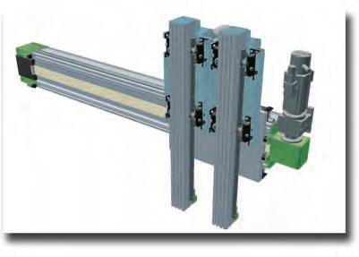
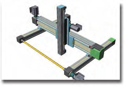
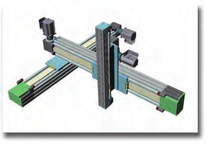

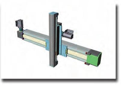
155 Standard assembly solutions Modline 1 82 M M-67

156 Sizing template Our Technical Support dept. is available to check sizing calculations. Please fill in the form with all the necessary data and send it to our technical dept., which will suggest the most suitable size according to the forces applied and precision required. Z-axis Y-axis eft side VERTICA Right side X-axis Motor eft side Right side HORIZONTA TRANSVERSE Y-axis X-axis M-68
157 Sizing request form Modline For a proper definition of the linear units, fill in the scaling request form and send it to the Technical Support Department. Date:... Filled in by... Company... Address... Phone...Fax Sizing template required data optional data MODINE linear modules ASSEMBY SOUTIONS (see page M-67) no. Z-axis Y-axis X-axis Total length z y x [mm] Total working load including EOAT (add Z axis for Y and X axes) Pc Py Px [kg] Equipment weight on carriage (gearbox, cylinder, OPTIONA) Paz Pay Pax [kg] Weight distributed on the beam (energy chain) Pdz Pdy Pdx [kg/m] Profile supports n n Max. projection (any cantilever, the largest) Sz Sy Sx [mm] Max. span dy dx [mm] Offset load s centre of gravity (X-axis) cx [mm] Offset load s centre of gravity (Y-axis) cy [mm] Offset load s centre of gravity (Z-axis) cz [mm] Any additional force F F F [N] +/- Offset additional force (X-axis) fx [mm] Offset additional force (Y-axis) fy [mm] Offset additional force (Z-axis) fz [mm] Possible distance between the carriages Dz Dy Dx [mm] Transmission performance η Assembly: vertical= 90 - slope = 30, 45, 60 - horizontal α= Stroke Speed Qz Vz Qy Vy Qx Vx [m/s] Acceleration Az Ay Ax [m/s 2 ] Cycle time Tz Ty Tx [s] Positioning accuracy +/- [mm] Repeatability +/- [mm] Work environment (temperature and cleanliness) Daily working cycles n Minimum service life requested [Km] M Working cycle Example working cycle Notes: M-69
158 Index Code page Code page Code page Code page Code page M M-59 A32-60 M-58 MCH 65 M-4 ZCE 170 M M M-59 A32-65 M-57 MCH 80 M-6 ZCE 220 M M M-59 A32-67 M-57 MCHH 105 M-9 ZCERQ 170 M M M-59 A32-80 M-58 MCR 105 M-7 ZCERQ 220 M M M-59 A32-85 M-57 MCR 65 M-3 ZCG 60 M M M-59 A39-25/5000 M-56 MCR 80 M-5 ZCG 90 M M M-59 A39-25/6000A M-56 MVH 105 M-12 ZC 100 M M M-59 A39-26/5000 M-56 MVHH 105 M-13 ZC 170 M M M-63 B30-53 M-56 MVR 105 M-11 ZC 220 M M M-63 B30-54 M-56 MVR 80 M-10 ZC 60 M M M-63 B30-55 M-56 MVS 105 M-12 ZC 90 M M M-63 B30-56 M-56 TCG 100 M-17 ZCRQ 100 M M M-55 B30-63 M-56 TCG 180 M-19 ZCRQ 170 M M M-55 B30-64 M-56 TCH 100 M-18 ZCRQ 220 M M M-55 B30-65 M-56 TCH 170 M-22 ZCRR 90 M M M-55 B30-66 M-56 TCH 180 M-20 ZCY 180 M M M-55 D32-40 M-57 TCH 200 M-24 ZMCP 105 M M M-55 D32-50 M-57 TCH 220 M-26 ZMC 105 M M M-55 B32-55 M-57 TCH 280 M-28 ZMCH 105 M M M-55 D32-60 M-57 TCH 360 M-30 KCH 100 M M M-54 B32-65 M-57 TCRQ 170 M-21 KCH 150 M M M-54 B32-67 M-57 TCRQ 180 M-19 KCH 200 M M M-54 B32-85 M-57 TCRQ 200 M-23 TECH 170 M M M-54 BD31-30 M-57 TCRQ 220 M-25 TECRR 180 M M M-54 BD31-40 M-57 TCRQ 280 M-27 TECH 180 M M M-55 BD31-50 M-57 TCRP 280 M M-58 A30-54 M-56 BD31-60 M-57 TCRP 360 M M-60 A30-55 M-56 E01-4 M-48 TCS 100 M M-60 A30-56 M-56 E01-5 M-49 TCS 170 M M-60 A30-64 M-56 F01-1 M-48 TCS 180 M M-60 A30-65 M-56 M 65X67 M-48 TCS 200 M M-60 A30-66 M-56 M 80X80 M-48 TCS 220 M M-60 A30-76 M-56 M 105X105 M-48 TCS 280 M M-60 A30-86 M-56 MA1-2 M-49 TCS 360 M M-60 A32-40 M-58 MA1-4 M-49 TVH 180 M M-60 A32-50 M-58 MA1-5 M-49 TVS 170 M M-59 A32-55 M-57 MCH 105 M-8 TVS 220 M-16 M-70
159
 211 95 747 0 www.rollon.de - info@rollon.de ROON B.V.")
 (0) 4 74 71 93 30 www.rollon.fr - infocom@rollon.fr ROON td - CHINA No.")
 973 300 5492 www.rolloncorp.com - info@rolloncorp.com ROON India Pvt. td.")
160 ROON S.p.A. - ITAY Via Trieste 26 I Vimercate (MB) Phone: (+39) infocom@rollon.it Rollon Branches & Rep. Offi ces Distributors Branches: ROON GmbH - GERMANY Bonner Strasse D Düsseldorf Phone: (+49) info@rollon.de ROON B.V. - NETHERANDS Ringbaan Zuid DB Zevenaar Phone: (+31) info@rollon.nl Rep. Offices: ROON S.p.A. - RUSSIA , Moscow, Varshavskoye shosse 17, building 1 Phone: +7 (495) info@rollon.ru ROON S.A.R.. - FRANCE es Jardins d Eole, 2 allée des Séquoias F imonest Phone: (+33) (0) infocom@rollon.fr ROON td - CHINA No. 16 Jin Wen Road, China, Shanghai, Phone: info@rollon.cn.com ROON Corporation - USA 101 Bilby Road. Suite B Hackettstown, NJ Phone: (+1) info@rolloncorp.com ROON India Pvt. td. - INDIA 1st fl oor, Regus Gem Business Centre, 26/1 Hosur Road, Bommanahalli, Bangalore Phone: (+91) info@rollonindia.in ROON td - UK The Works 6 West Street Olney Buckinghamshire, United Kingdom, MK46 5 HR Phone: +44 (0) info@rollon.uk.com Regional Manager: ROON - SOUTH AMERICA R. Joaquim Floriano, 397, 2o. andar Itaim Bibi , São Paulo, BRASI Phone: +55 (11) info@rollonbrasil.com ROON - JAPAN 3F Shiodome Building, Kaigan, Minato-ku, Tokyo Japan Phone info@rollon.jp Consult the other ranges of products Actuator ine All addresses of our global sales partners can also be found at The content of this document and its use are subject to the general terms of sale of ROON available on the web site Changes and errors expected. The text and images may be used only with our permission. AT2_GC_EN_08/17
Actuator Line. General catalogue English. Part 2
 Actuator ine Part 2 General catalogue English www.motionindustries.com www.rollon.com When you move. We move Rollon S.p.A. was founded in 1975 as a manufacturer of linear motion components. Today Rollon
Actuator Line. General catalogue English. Part 2
 Actuator ine Part 2 General catalogue English www.rollon.com www.rollon.com When you move. We move Rollon S.p.A. was founded in 1975 as a manufacturer of linear motion components. Today Rollon group is
Index. Order code setting 48 INTRODUCTION EUROPEAN DISTRIBUTORS
 Index 1 EUROPEAN DISTRIBUTORS AGORA TECHNIQUE S.A.R.L. Parc Volta 3 Rue Parmentier F- 94140 Alfortville Tel. +33 145 18 43 70 Fax.. +33 145 18 43 71 E-mail: agora@agora-technique.com DRECKSHAGE August
Belt and screw type linear modules
 Belt and screw type linear modules TECNO CENTER s.r.l. C.so Lombardia, 41-10078 Venaria Reale (TO) ITALY Tel. +39 011 455 11 21 Fax. +39 011 455 75 95 E-mail: info@tecno-center.it www.tecno-center.it AUTHORIZED
Sizes 50, 65, 80. Presence of internal channels for re-lubrication Large range of axis mounting accessories
 > Series 5E electromechanical axis C_Electrics > 207 Series 5E electromechanical axis New models Sizes 50, 65, 80 Multiposition system with transmission of the movement with toothed belt Suitable for high
Actuator System Line. Product Overview English.
 Actuator System Line Product Overview English When you move. We move Rollon S.p.A. was founded in 1975 as a manufacturer of linear motion components. Today Rollon group is a leading name in the design,
Sizes 50, 65, 80. Accessories for cables fixing. Presence of internal channels for re-lubrication Large range of axis mounting accessories
 > Series 5E electromechanical axis C_Electrics > 206 Series 5E electromechanical axis New Sizes 50, 65, 80 Multiposition system with transmission of the movement with toothed belt Suitable for high dynamics
ACTUATORLINE ELM series
 ACTUATORLINE ELM series www.rolloncorp.com www.motiontech.com.au Contents Series Overview 1 The Components 2 The Linear Motion System 3 Main Technical Characteristics 4 ELM 50 SP 6 ELM 65 SP 7 ELM 80 SP
Telescopic Line. General catalogue English.
 Telescopic Line General catalogue English www.rollon.com When you move. We move Rollon S.p.. was set up in 1975 as a manufacturer of linear motion components. Today Rollon group is a leading name in the
Ball Rail Systems RE / The Drive & Control Company
 Ball Rail Systems RE 82 202/2002-12 The Drive & Control Company Rexroth Linear Motion Technology Ball Rail Systems Roller Rail Systems Standard Ball Rail Systems Super Ball Rail Systems Ball Rail Systems
V SWISS MADE LINEAR TECHNOLOGY
 Excerpt from main catalogue inear modules V 11-15 SWISS MDE INER TECHNOOGY ine Tech inear modules Table of contents Product overview 6 7 Design fundamentals / ubrication / Maintenance 8 Profile cross-sections
Profi le rail guides LLR
 Profi le rail guides LLR Content The SKF brand now stands for more than ever before, and means more to you as a valued customer. While SKF maintains its leadership as the hallmark of quality bearings throughout
V SWISS MADE LINEAR TECHNOLOGY
 Compact units Excerpt from main catalogue SWISS MADE LINEAR TECHNOLOGY V 11-15 Line Tech compact units Table of contents Product overview 106 107 Design fundamentals / Lubrication / Maintenance 108 Profile
Any reproduction, even partial, is allowed only by written permission by Rollco.
 LINEAR UNIT E-SMART Every care has been taken to ensure the accuracy of the information contained in this catalogue, but no liability can be accepted for any errors or omissions. We reserve the right to
SNR, YOUR GUIDE TO LINEAR MODULES
 SNR, YOUR GUIDE TO LINEAR MODULES A bearing manufacturer known across the world For almost a century NTN-SNR has been focusing on the development, design and manufacture of bearings. Today NTN-SNR has
Compact Modules. with ball screw drive and toothed belt drive R310EN 2602 ( ) The Drive & Control Company
 The Drive & Control Company") with ball screw drive and toothed belt drive R310EN 2602 (2007.02) The Drive & Control Company Bosch Rexroth AG Linear Motion and Assembly Technologies Ball Rail Systems Roller Rail Systems Linear Bushings
with ball screw drive and toothed belt drive R310EN 2602 (2007.02) The Drive & Control Company Bosch Rexroth AG Linear Motion and Assembly Technologies Ball Rail Systems Roller Rail Systems Linear Bushings
Linear Drive with Toothed Belt and Integrated Guide with Recirculating Ball Bearing Guide with Roller Guide Series OSP-E..BHD
 Linear Drive with and Integrated Guide with Recirculating Ball Bearing Guide with Roller Guide Contents Description Page Overview 11-14 Version with Recirculating Ball Bearing Guide Technical Data 15-17
Any reproduction, even partial, is allowed only by written permission by Rollco.
 EASYSLIDE Every care has been taken to ensure the accuracy of the information contained in this catalogue, but no liability can be accepted for any errors or omissions. We reserve the right to make changes
...components in motion. Easy Rail
 ...components in motion Easy Rail Easy Rail Introduction The Easy Rail family have a compact cross-section and low-friction movement. Robust and Long Service Life Easy Rail s range of cross-sectional rail
Contents. Page. 1. Product description. 2. The AXC line of linear axes. 3. AXLT line of linear tables. AXC and AXS product overview...
 SNR Industry Contents Page 3 1. Product description AXC and AXS product overview... 6-8 Dynamic load ratings of the linear motion systems... 9 Compact modules... 10-11 Linear tables... 12 Telescopic axes...
 A LEADING MANUFACTURER IN LINEAR MOTION GERALD SUMMERS is now an authorised distributor of Rollon TEL: 0800 055 6663 E-MAIL: SALES@GERALD-SUMMERS.CO.UK WWW.GERALD-SUMMERS.CO.UK CURVILINE www.rollon.com
LINEAR ACTUATORS. hepcomotion.com
 LINEAR ACTUATORS hepcomotion.com PDU2 Belt Driven DLS Belt Driven 3 4 SBD Belt Driven A SDM Ball Screw HDCS Heavy Duty Ball Screw 8 9 LINEAR ACTUATORS ctuator HDLS Heavy Duty Belt Driven PSD Ball Screw
TELESCOPIC RAIL HEAVY
 TELESCOPIC RAIL HEAVY Every care has been taken to ensure the accuracy of the information contained in this catalogue, but no liability can be accepted for any errors or omissions. We reserve the right
Linear Axes Technical Data Summary
 components Technical Data Summary Pneumatic Axes Electrical Axes LM 6 P LM 8 P LM 8 PV LM 10 P LM 6 PE LM 8 PE LM 8 PEV LM 10 PE Standard stroke lengths [mm]: h 0-150 Overall length [mm]: L 408 468 468
Rotary Indexing Table with Face Gear
 FIBROTAKT Rotary Indexing Table with Face Gear Product No. 1.001.00.00.00.01000 1 7975 006 4 08/007 Contents FIBRO The latest technology with a tradition of service /3 FIBROTAKT at a glance 4 Technical
Actuator Line. General catalogue English. Part 1
 ctuator Line Part 1 General catalogue English www.rollon.com When you move. We move Rollon.p.. was founded in 1975 as a manufacturer of linear motion components. Today Rollon group is a leading name in
 www.motiontech.com.au Copyright SERVOMECH This catalogue contents are under publisher copyright and may not be reproduced unless permission is agreed. Every care has been taken to ensure the accuracy of
Easy Slide Rails ov -easy_slide_divider - U pdated
 Easy Slide Rails ov-easy_slide_divider - Updated - 18-09-2017 163 Easy Slide Rails Easy Slide Rails Introduction The Easy Slide family of linear rails have a compact cross-section and low-friction movement.
Vertical Linear Drive with Toothed Belt and Integrated Recirculating Ball Bearing Guide Series OSP-E..BV
 Vertical Linear Drive with and Integrated Recirculating Ball Bearing Guide Series OSP-E..BV Contents Description Page Overview 25-28 Technical Data 29-31 Dimensions 32-33 25 Parker Hannifin Corporation
Linear Systems Solutions Defining the Future with the Schaeffler Group
 Linear Systems Solutions Defining the Future with the Schaeffler Group LINEAR ACTUATORS Linear Solutions Provider Part retrieval systems, palletizers, custom tool changers, and dispensing robots are a
ndustr SNR our guide to linear modules
 ndustr SNR our guide to linear modules SNR A bearing manufacturer known across the world For almost a century SNR has been focusing on the development, design and manufacture of bearings. Today SNR has
Vertical Linear Drive with Toothed Belt and Integrated Recirculating Ball Bearing Guide Series OSP-E..BV
 Vertical Linear Drive with and Integrated Recirculating Ball Bearing Guide Series OSP-E..BV Overview...25-28 Technical Data...29-31 Dimensions...32-33 25 Features TOOTHED BELT DRIVE FOR VERTICAL MOVEMENTS
Linear Actuator with Toothed Belt and Integrated Roller Guide Series OSP-E..BHD
 inear Actuator with Toothed Belt and Integrated Roller Guide Series OSP-E..BHD Contents Description Data Sheet No. Page Overview 1.15.001E 11-14 Technical Data 1.15.002E-1 to 3 15-17 Dimensions 1.15.002E-4
Uniline System FrontespizioUnilineSystem.indd 1 22/11/ :32:41
 Uniline ystem 1 Uniline series Uniline series Uniline series description ig. 1 Uniline is a family of ready-to-install linear actuators. They consist of internal ompact Rail roller sliders and steel-reinforced
Introduction. Stainless Steel Cover. Removable Carriage Plate. Mounting Platform. Limit Switch & Bracket. Aluminum Beam.
 Introduction The HepcoMotion SBD is an exceptionally rugged, quiet and precise linear unit. It uses super-smooth Hepco LBG caged linear ball guides having such high load capacity that system life is rarely
Precision Modules PSK
 Precision Modules PSK The Drive & Control Company Rexroth Linear Motion Technology Ball Rail Systems Roller Rail Systems Standard Ball Rail Systems Super Ball Rail Systems Ball Rail Systems with Aluminum
Vertical Linear Drive with Toothed Belt and Integrated Recirculating Ball Bearing Guide Series OSP-E..BV
 Vertical Linear Drive with Toothed Belt and Integrated Recirculating Ball Bearing Guide Series OSP-E..BV Contents Description Page Overview 25-28 Technical Data 29-33 Dimensions 34 Order Instructions 35
Miniature Ball Rail Systems
 R310EN 2210 (2004.06) The Drive & Control Company 2 Bosch Rexroth AG Linear Motion and Assembly Technologies Miniature-BRS R310EN 2210 (2004.06) Linear Motion Systems Ball Rail System Standard Ball Rail
HepcoMotion MHD Heavy Duty Track Roller Guidance System
 Motion Without Limits HepcoMotion MHD Heavy Duty Track Roller Guidance System product overview The HepcoMotion MHD system provides an accurate, durable and low friction linear guide which is particularly
CKR Compact Modules with Ball Rail Guides and Toothed Belt Drive. The Drive and Control Company
 CKR Compact Modules with Ball Rail Guides and Toothed Belt Drive The Drive and Control Company Bosch Rexroth Corp. Linear Motion and Assembly Technologies CKR RE 8 615 (03.006) Rexroth Linear Motion Technology
Compact. Fast. Productive. DRL Lift/Swivel Unit
 DRL Compact. Fast. Productive. DRL Lift/Swivel Unit Compact lift/swivel unit consisting of a strong short-stroke cylinder and a rack pinion swivel drive. Field of Application For use in clean and slightly
EASY RAIL.
 EASY RAIL www.rollon.com About Rollon Development of global business Continual expansion and optimization of the portfolio 1975 Parent company, Rollon S.r.l., founded in Italy 1991 Founding of Rollon GmbH
 UNILINE www.motiontech.com.au bout Rollon Development of global business Continual expansion and optimization of the portfolio 1975 Parent company, Rollon S.r.l., founded in Italy 1991 Founding of Rollon
R310EN 2211 ( ) The Drive & Control Company
 The Drive & Control Company") eline Ball Rail Systems R310EN 2211 (2006.04) The Drive & Control Company Bosch Rexroth AG Linear Motion and Assembly Technologies Ball Rail Systems Roller Rail Systems Linear Bushings and Shafts Ball
eline Ball Rail Systems R310EN 2211 (2006.04) The Drive & Control Company Bosch Rexroth AG Linear Motion and Assembly Technologies Ball Rail Systems Roller Rail Systems Linear Bushings and Shafts Ball
FLEXIBLE COUPLINGS - RIGID COUPLINGS Up to Nm of torque and 205 mm bores
 Edition 10/2014 www.comintec.it FLEXIBLE COUPLINGS - RIGID COUPLINGS Up to 130.000 Nm of torque and 205 mm bores (BACKLASH FREE) Technology for Safety FLEXIBLE COUPLINGS - RIGID COUPLINGS (BACKLASH FREE):
LM SERIES LINEAR MODULE
 LM SERIES LINEAR MODULE THE LM RODLESS LINEAR ACTUATOR RACO s LM Linear Modules are lightweight positioning elements, which can be easily configured into a wide variety of multiple axis motion systems.
V-Drive Technical brochure. Maximum power density Constant torsional backlash Supreme smooth running
 V-Drive Technical brochure Maximum power density Constant torsional backlash Supreme smooth running V-Drive Basic The quiet endurance runner Servo worm gearheads with output shaft and hollow shaft. The
Dynamic Elements Linear Slides Mechanical Drive Elements Accessories for Mechanical Drive Elements
 8 Dynamic Elements Mechanical Drive Elements Accessories for Mechanical Drive Elements The Dynamic Elements product group of the MB Building Kit System contains components which enable precise linear movement.
Берг АБ Тел. (495) , факс (495)
 , факс (495)") HepcoMotion SBD Sealed Belt Drive www.bergab.ru Берг АБ bergab@ya.ru Тел. (495)-228-06-21, факс (495) 223-3071 Introduction The HepcoMotion SBD is an exceptionally rugged, quiet and precise linear unit.
HepcoMotion SBD Sealed Belt Drive www.bergab.ru Берг АБ bergab@ya.ru Тел. (495)-228-06-21, факс (495) 223-3071 Introduction The HepcoMotion SBD is an exceptionally rugged, quiet and precise linear unit.
HepcoMotion. SBD Sealed Belt Drive
 HepcoMotion SBD Sealed Belt Drive Introduction The HepcoMotion SBD is an exceptionally rugged, quiet and precise linear unit. It uses super-smooth Hepco LBG caged linear ball guides having such high load
A5 BELT-DRIVEN RODLESS ELECTRIC AXIS, SERIES ELEKTRO BK
 BELT-DRIVEN RODLESS ELECTRIC AXIS, SERIES ELEKTRO BK Belt-driven rodless electric axis with a V-Lock interface. The structure features an extremely lightweight yet high-strength anodised aluminium extruded
mechanics LES functional overview LES 4 LES 6 LES 5
 LES functional overview LES 4 with spindle drive Overview 2-54 2-56 LES 6 2-58 with spindle drive LES 5 2-60 with spindle drive Calculations 2-62 Combination examples Motor modules Clutch housing Motor
LoPro aluminium based slide system
 LoPro aluminium based slide system Introducing the Hepco LoPro Hepco LoPro has been introduced to provide the designer with a lightweight yet rugged linear slide system. LoPro is aluminiumbased with steel
MECHANICS. Aluminium profiles Linear guides Drive elements Linear units Rotational units
 Aluminium profiles...2-2 Linear guides...2-18 Drive elements...2-44 Linear units...2-52 Rotational units...2-94 Aluminium profiles Aluminium profiles PP profiles Panel profiles PP PP 100 PP 1 PP 200 Overview
NEW. Linear Ball Bushing Bearings and 60 Case Shafting. Profile Rail Linear Guides
 Linear Ball Bushing Bearings and 60 Case Shafting Thomson invented the ball bushing bearing over 60 years ago and has since been the recognized leader in this field. Our linear products provide low friction,
ZERO BACKLASH GEARING
 ZERO BACKLASH GEARING Based on Nexen s innovative Roller Pinion technology, the Geared Bearing comes complete with a gear and a precision grade, high capacity bearing. With a wide range of sizes and ratios,
HepcoMotion PSD80. screw driven linear actuator
 HepcoMotion PSD80 screw driven linear actuator Introduction The HepcoMotion PSD80 is a new screw driven linear unit, which is a companion to the popular and cost-effective PDU2 range of belt driven units,
BACKLASH FREE AND STANDARD JAW COUPLING
 BACKLASH FREE AND STANDARD JAW COUPLING Up to 9.600 Nm of torque and 130 mm bore GAS/SG e GAS 25 Technology for Safety GAS/SG-ST - backlash free jaw coupling «in steel»: introduction Made in steel fully
Curviline FrontespizioCurviline.indd 1 07/10/ :24:20
 Curviline When you move. We move Rollon S.p.A. was founded in 1975 as a manufacturer of linear motion components. Today Rollon group is a leading name in the design, production, and sale of linear rails,
Product Description. Characteristic features R310A 2402 ( ) Linear Modules MLR
 Linear Modules MLR") 9 Bosch Rexroth Corporation R310A 40 (1.11) MLR Product Description Characteristic features MLR...: with Cam Roller Guide and Toothed Belt Drive for high-speed applications (up to 10 m/s) with Cam Roller
9 Bosch Rexroth Corporation R310A 40 (1.11) MLR Product Description Characteristic features MLR...: with Cam Roller Guide and Toothed Belt Drive for high-speed applications (up to 10 m/s) with Cam Roller
Linear Drive with Ball Screw Drive Series OSP-E..SB
 Linear Drive with Ball Screw Drive Series OSP-E..SB Contents Description Data Sheet No. Page Overview 1.30.001E 47-50 Technical Data 1.30.002E-1 to 5 51-55 Dimensions 1.30.002E-6, -7 56-57 Order instructions
Cam roller guide LF6S complete axis
 Y 1- MGE 1. Linear guides Z Mz Cam roller guide LFS complete axis X Mx M y [mm] B [mm] Fully assembled cam roller guide Stroke and trolley length can be individually selected Rail profile screwed onto
FLEXIBLE COUPLINGS - RIGID COUPLINGS Up to Nm of torque and 205 mm bores
 Edition 10/2014 www.comintec.it FLEXIBLE COUPLINGS - RIGID COUPLINGS Up to 130.000 Nm of torque and 205 mm bores (BACKLASH FREE) Technology for Safety FLEXIBLE COUPLINGS - RIGID COUPLINGS (BACKLASH FREE):
ELECTRIC AXIS ELEKTRO SVAK SERIES ACTUATORS
 ELECTRIC AXIS ELEKTRO SVAK SERIES 1 ELECTRIC AXIS ELEKTRO SVAK SERIES This belt-driven rodless electric actuator is characterised by the fact that the motor and reducer unit is integral with the carriage,
Linear Actuator with Toothed Belt Series OSP-E..B
 Linear Actuator with Toothed Belt Series OSP-E..B Contents Description Data Sheet No. Page Overview 1.20.001E 21-24 Technical Data 1.20.002E-1 to 5 25-29 Dimensions 1.20.002E-6 30 Order Instructions 1.20.002E-7
ML Series MINIATURE SCREW-DRIVEN LINEAR ACTUATOR LOW COST SOLUTION FOR PRECISION POSITIONING IN COMPACT SPACES!
 ML Series MINIATURE SCREW-DRIVEN LINEAR ACTUATOR Compact and easy to install, a low cost linear solution perfectly suited for the medical industry, life science and small scale automation applications.
BACKLASH FREE AND STANDARD JAW COUPLING
 BACKLASH FREE AND STANDARD JAW COUPLING Up to 9.600 Nm of torque and 130 mm bore GAS/SG e GAS 25 Technology for Safety 10-2018 GAS/SG-ST - backlash free jaw coupling «in steel»: introduction Made in steel
Cam roller guide LF12S complete axis
 Y -16 MGE. Linear guides Z Mz Cam roller guide LF1S complete axis X Mx M y [mm] B [mm] Fully assembled cam roller guide Stroke and trolley length can be individually selected Rail profile screwed onto
CURVILINE.
 CURVILINE www.rollon.com About Rollon Development of global business Continual expansion and optimization of the portfolio 1975 Parent company, Rollon S.r.l., founded in Italy 1991 Founding of Rollon GmbH
Portal modules.
 Portal modules www.comoso.com www.comoso.com Portal modules PORTAL MODULES Series Size Page Portal modules PMP 114 PMP 16 118 PMP 25 124 EPM 130 EPM 37 138 EPM 48 146 The SCHUNK program offers linear technology
SPIRACON. ROLLER SCREWS SPIRACON PRODUCT CATALOGUE
 SPIRACON ROLLER SCREWS PRODUCT CATALOGUE SPIRACON www.powerjacks.com TOTAL CAPABILITY IN ACTUATION Power Jacks is a world leader and pace-setter in the field of mechanical linear actuation and power transmission,
TELESCOPIC-LINE. Semi-telescopic-rail LST. Telescopic-rail LSE. Linear guides with ball-cage LSS
 TELESCOPIC-LINE Semi-telescopic-rail LST Telescopic-rail LSE Linear guides with ball-cage LSS 1 Ball rails LSS, LST and LSE The ball rails produced by Nadella are very compact and flexible products. Made
Modular. Precise. Robust. AGE-S-XYZ Compensation Unit
 Modular. Precise. Robust. AGE-S-XYZ Compensation Unit Compensation unit compensating in XY- and Z-direction. Field of Application Palletizing, joining, and assembly of workpieces Advantages Your benefit
Linear Motion. Optimized.
 Thomson - Linear Motion. Optimized. Linear Motion. Optimized. Often the ideal design solution is not about finding the fastest, sturdiest, most accurate or even the least expensive option. Rather, the
ROTARY MODULES. Rotary modules
 Rotary modules Rotary modules ROTARY MODULES Series Size Page Rotary modules RM swivel unit 156 RM 08 160 RM 10 162 RM 12 164 RM 15 168 RM 21 172 RM rotor 176 RM 50 180 RM 110 182 RM 200 184 RM 310 186
RACK JACK. Synchronous Lifting Systems
 RACK JACK Synchronous Lifting Systems RACK JACK (ROUND RACK TYPE) Operation The Rack Jack from WMH Herion provides simple synchronous lifting motion. The system of rack and pinion transforms linear motion
Precision in Accuracy
 Your addition in transmission. Precision in Accuracy MELIOR MOTION PRECISION GEARBOX PSH-D SPECIAL PRECISION GEARBOXES The Premium Group Premium Stephan Hameln, Germany Design, development and production
Rodless cylinders. Series General. Construction characteristics. Technical characteristics. Use and maintenance
 Series 1600 Rodless cylinders General The purpose of producing a rodless cylinder is to provide a space saving option over conventional cylinders. On a traditional rod type cylinder, the total space occupied
Linear Actuator with Toothed Belt and Integrated Guide with Roller Guide with Recirculating Ball Bearing Guide. Series OSP-E..BHD
 inear ctuator with Toothed elt and Integrated Guide with Roller Guide with Recirculating all earing Guide Series OSP-E..HD Contents Description Page Overview 11-14 Version with Roller Guide Technical Data
Heavy Duty Ball Screw Linear Actuators
 Heavy Duty Ball Screw Linear Actuators Thrust From 2,000 to 25,000 lbf Heavy Wall Steel Construction Longest Life Simultaneous High Thrust with High Speed Piston with Rugged Anti Rotation Feature Sealed
Linear Actuator with Ball Screw Series OSP-E..S. Contents Description Overview Technical Data Dimensions 89
 Linear Actuator with Ball Screw Series OSP-E..S Contents Description Page Overview 79-82 Technical Data 83-88 Dimensions 89 79 The System Concept ELECTRIC LINEAR ACTUATOR FOR HIGH ACCURACY APPLICATIONS
PERFORMANCE AND KNOW-HOW
 PRODUCT PROGRAM PERFORMANCE AND KNOW-HOW The NADELLA Group is today an absolute specialist for mechanical motion technology, offering you numerous products, the appropriate know-how and service for this
Product Specification
 Product Specification Track Motion IRBT 6002S/4002S 3HXD 7103-1 M99 February 1999 ABB Flexible Automation The information in this document can be subject to change without prior notice and should not be
Linear Bushings and Shafts. The Drive & Control Company
 Linear Bushings and s The Drive & Control Company 2 Bosch Rexroth Corp. Linear Motion and Assembly Technologies Linear Bushings R310A 3100 Linear Motion Technology Ball Rail Systems Standard Ball Rail
Modular. Precise. Robust. AGE-S-XYZ Compensation Unit
 AGE-S Modular. Precise. Robust. AGE-S-XYZ Compensation Unit Compensation unit compensating in XY- and Z-direction Field of Application Palletizing, joining, and assembly of workpieces Advantages Your benefit
Courtesy of CMA/Flodyne/Hydradyne Motion Control Hydraulic Pneumatic Electrical Mechanical (800)
") 01_1 Miniature st Headline_36 Ball Rail pt/14.4 Systems mm second line 2 Linear Motion and Assembly Technologies Miniature Ball Rail Systems Ball Rail Systems Roller Rail Systems Linear Bushings and Shafts
01_1 Miniature st Headline_36 Ball Rail pt/14.4 Systems mm second line 2 Linear Motion and Assembly Technologies Miniature Ball Rail Systems Ball Rail Systems Roller Rail Systems Linear Bushings and Shafts
MT Series MTB 42 BELT DRIVEN LINEAR ACTUATOR
 MT Series MTB BELT DRIVEN LINEAR ACTUATOR LINEAR ACTUATOR TECHNOLOGY The MT Series offers a number of profile sizes with multiple design configurations to fit almost any application. TECHNICAL DATA FEATURES
Linear Drive with Toothed Belt Series OSP-E..B. Contents Description Overview Technical Data Dimensions Order Instructions 46
 Linear Drive with Toothed Belt Contents Description Page Overview 35-38 Technical Data 39-43 Dimensions 44-45 Order Instructions 46 35 The System Concept ELECTRIC LINEAR DRIVE FOR POINT-TO-POINT APPLICATIONS
Sheet 1 Variable loading
 Sheet 1 Variable loading 1. Estimate S e for the following materials: a. AISI 1020 CD steel. b. AISI 1080 HR steel. c. 2024 T3 aluminum. d. AISI 4340 steel heat-treated to a tensile strength of 1700 MPa.
Positioning Systems Linear Motor Systems
 www.hiwin.de Positioning Systems Linear Motor Systems HIWIN GmbH Brücklesbünd 2 D-77654 Offenburg Phone +49 (0) 7 81 9 32 78-0 Fax +49 (0) 7 81 9 32 78-90 info@hiwin.de www.hiwin.de All rights reserved.
Index INDEX. Product overview Technical data... 5 RHL Sliders for RHL80: V100, V250 & V RHL
 LINEAR UNIT RHL Svanemærket tryksag 541-713 INDEX Index Product overview... 4 Technical data... 5 RHL... 6 Sliders for RHL: V1, V25 & V5... 7 RHL11... 8 Sliders for RHL11: V2 & V5... 9 Mounting Plates...
General Purpose Motion Control Couplings
 General Purpose Motion Control s Sliding Disc (Oldham) Universal ateral (Uni-at) Backlash-free up to 10 8 turns Can tolerate large misalignments Slight damping characteristics Flex-free mechanical action
Берг АБ Тел. (495) , факс (495)
 , факс (495)") AUTOMATION Linear- and Rotary Modules Table of Contents 1 Product Overview............................................. 4 1.1 Selection of the Linear Modules................................. 8 1.2 Selection
AUTOMATION Linear- and Rotary Modules Table of Contents 1 Product Overview............................................. 4 1.1 Selection of the Linear Modules................................. 8 1.2 Selection
Linear Motion Technology Handbook. The Drive & Control Company
 Linear Motion Technology Handbook The Drive & Control Company 1-2 Bosch Rexroth AG Linear Motion Technology Handbook R310EN 2017 (2006.07) Linear Motion and Assembly Technologies www.boschrexroth.com/brl
ELECTRIC ACTUATOR - RODLESS ELEKTRO SK SERIES ACTUATORS
 ELECTRIC ACTUATOR - RODLESS ELEKTRO SK SERIES 1 ELECTRIC AXIS - RODLESS ELEKTRO SK SERIES Electric axis without screw piston rod, with V-Lock interface. The cylinder frame is made of anodized extruded
Bevel gearboxes. Catalogue
 Bevel gearboxes Catalogue INDEX Bevel gearbox description... page 2 Manufacturing features... page 2 Materials and components... page 4 Bevel gearbox selection... page 5 Thermal power limit... page 7
LINEAR UNITS CT & MT
 LINEAR UNITS CT & MT Every care has been taken to ensure the accuracy of the information contained in this catalogue, but no liability can be accepted for any errors or omissions. We reserve the right
Product overview. 10 Bosch Rexroth Corporation Compact Modules R310A 2602 ( ) Compact Modules CKK. Compact Modules with ball screw drive (CKK)
 Compact Modules CKK. Compact Modules with ball screw drive (CKK)") 10 Bosch Rexroth Corporation R310A 2602 (2008.09) CKK with ball screw drive (CKK) Product overview are precision, ready-to-install linear motion systems characterized by their high performance and compact
10 Bosch Rexroth Corporation R310A 2602 (2008.09) CKK with ball screw drive (CKK) Product overview are precision, ready-to-install linear motion systems characterized by their high performance and compact
Easyslide FrontespizioEasyslide.indd 1 21/05/ :26:17
 Easyslide When you move. We move Rollon S.p.A. was founded in 1975 as a manufacturer of linear motion components. Today Rollon group is a leading name in the design, production, and sale of linear rails,
mechanics LES functional overview LES 4 LES 6 LES 5
 LES functional overview LES 4 Overview B-36 B-38 with spindle drive LES 6 B-40 with spindle drive LES 5 B-42 with spindle drive Combination examples Motor modules Clutch housing Motor leads Installation