D-90 Type DE Double Enveloping Worm Gear Speed Reducers.
|
|
|
- Cecil Small
- 5 years ago
- Views:
Transcription

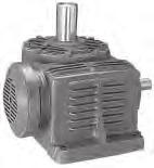
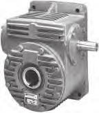
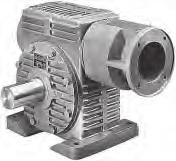
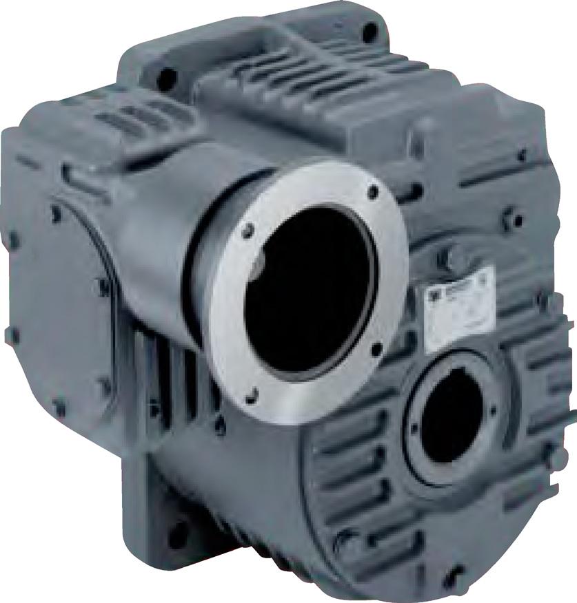

1 T D-90 Type DE Double Enveloping Worm Gear Speed Reducers
 shafts and output shafts provide maximum thrust and overhung load capacity and assure long service life.")
2 WINSMITH D-90 TYPE DE S NEW DOUBLE ENVELOPING WORM GEAR REDUCERS HIGH POWER HIGH EFFICIENCY COMPACT DESIGN WORM SHAFT Heat-treated alloy steel worm. BEARINGS Tapered roller bearings on both input (worm) shafts and output shafts provide maximum thrust and overhung load capacity and assure long service life. LUBRICATION FLOW Increased flow of lubricant in the mesh creates more efficient operation than cylindrical worm meshes. DUAL CONTACT MESH Two separate contact paths at the mesh reduces contact pressure, increases tooth contact and power density. OIL SEALS High quality seals in contact with precision ground shafts assure maximum seal life and leakproof protection. GEARS High grade centrifugally cast or chill cast bronze. OUTPUT SHAFT Heat treated alloy steel. PLUGS Fill, level and drain plugs conveniently located. HOUSING Rugged, close grain cast iron. Mounting feet are integral with the housing for strength and rigidity. RIBBED EXTERIOR Quicker heat dissipation for power dense design. LUBRICATION All units factory filled with synthetic hydrocarbon lubricant to the proper level...ready for service on delivery. Every unit quality certified and test run prior to packaging and shipping.


3 TABLE OF CONTENTS EASY SELECTION Page(s) Index of Models How to Select How to Order Horsepower, Torque Ratings, Efficiency and Overhung Load SINGLE REDUCTION Size Size Size Size Size DOUBLE REDUCTION Size Size Size Size Size DIMENSIONS, PARTS LIST, SHAFT ARRANGEMENT NEW! 941 MDTX MODEL See page 76 for complete product specifications. NON-MOTORIZED REDUCER DIMENSIONS SINGLE REDUCTION DB/FDB DT/FDT DV/FDV DSF/FDSF DSR/FDSR DL/FDL DOUBLE REDUCTION DBD DTD DVD DSFD DSRD DLD HELICAL/WORM DTX MOTORIZED REDUCER DIMENSIONS SINGLE REDUCTION CDB/CFDB CDT/CFDT CDV/CFDV CDSF/CFDSF CDSR/CFDSR CDL/CFDL DOUBLE REDUCTION CDBD/MDBD CDTD/MDTD CDVD/MDVD CDSFD/MDSFD CDSRD/MDSRD CDLD/MDLD HELICAL/WORM MDTX ENGINEERING DATA GENERAL ENGINEERING INFORMATION Shaft Arrangement and Relative Shaft Rotation Gear Sets Standard Mounting Positions Horsepower, Torque, Efficiency Self Locking Worm Gear Reducers Backlash, Run-In Service Factors Overhung Load Gearing Inertia Values WK DISTRICT SALES OFFICES AND SERVICE CENTERS WINSMITH SERVICE CENTERS Terms and Conditions District Sales Offices and Service Centers Inside Back Cover 1
4 SELECTION ISSUES WINSMITH HAS THE RIGHT CHOICE: SINGLE OR DOUBLE ENVELOPING WORM GEAR PRODUCTS Single enveloping worm gear products depend on the mesh of one to two gear teeth to transfer and multiply torque. This type of mesh concentrates the work being done to a relatively small contact area. The worm is made as a cylindrical component with the outer diameter the same through the length of the threaded section. The teeth on the gear are contoured to envelop the worm thread, thus the term single enveloping worm gear. The wider distribution of load along with the improved lubrication characteristics in the double enveloping gear mesh create an efficient, power dense product. Double enveloping worm gear products depend on the mesh of several gear teeth, up to 1 8 of the gear circumference, to transfer and multiply torque (ie. 60:1 gear set with a 60 tooth gear or.125 x 60 = 7.5 teeth in mesh). This is made possible by contouring the worm threaded section to the gear. This contouring provides the second enveloping condition, thus the term double enveloping worm gear. The additional teeth in contact in a double enveloping gear set, two to four times more than in a single enveloping gear set, increases the total contact area in the mesh by a similar amount. In addition, lubrication between the worm and gear is improved due to a more favorable direction of contact lines in the mesh relative to worm rotation. This results in ratings for double enveloping gear sets that are two to four times the ratings for single enveloping gearsets of similar size. C-LINE & D-90 TYPE SE Cylindrical worm and enveloping gear create single enveloping product. D-90 TYPE DE Contoured worm and enveloping gear create double enveloping product. SINGLE ENVELOPING VS DOUBLE ENVELOPING PRODUCT SELECTION CRITERIA SELECTION ISSUE SINGLE ENVELOPING DOUBLE ENVELOPING REMARKS C-LINE D-90 SE D-90 DE Ratio Range :1 4-10,000:1 5-10,000:1 D-90 DE triple reduction Single & Double Reduction available upon request Power Density Good Fair Very Good Better at high ratio Max Torque Capacity Medium Low High DE up to new levels Efficiency Fair Good Very Good Best at low ratios Catalog Input Speed 1800 RPM 3000 RPM 1800 RPM Motion control products go up to 4000 RPM Backlash arc minutes arc minutes arc minutes Motion control products go down to 2 arc minutes Output Shaft Overhung Fair Good Very Good As it relates to center distance Load Capacity Price per in.-lbs. of Output Fair Good Very Good DE best buy at any ratio Torque Inertia Fair Good Very Good Power dense DE low in inertia Motorized Quill Input Single Reduction Yes Yes No DE requires 2 input bearings Double Reduction Yes Yes Yes to insure proper mesh Motorized Coupling Input Single Reduction Yes Yes Yes Many adapted to servo motors Double Reduction Yes Yes Yes 2


5 D-90 TYPE DE WHY WINSMITH DOUBLE ENVELOPING WINSMITH has a long history of product development leadership in the enclosed gear product industry. Double enveloping worm gear technology represents the leading edge in gear product development. The technology has been around for awhile, but has never been easily available to the Power Transmission market place. WINSMITH has combined years of can do product development expertise with the latest in manufacturing technology to develop this high performance product line. DEVELOPMENT OF A UNIQUE TECHNOLOGY EFFICIENCY The power of the WINSMITH double enveloping worm gear products is more than an increased number of teeth in mesh. WINSMITH double enveloping worm gear products also include a dual contact pattern on the gear teeth to reduce contact pressure. This reduced pressure along with the wide spread of the load through multiple teeth create a very efficient method to multiply torque. HIGH TORQUE Center distances from 4" to 8" offer a range of torque well beyond most competitive worm gear products. This additional capacity is now packaged in a compact speed reducer. VERSATILITY The WINSMITH double enveloping worm product was developed to allow the highest number of models from the smallest number of parts. Each housing serves as the building block for more than one model. FLEXIBILITY The extensive product development done at WINSMITH allows for creative use of the technology to solve problems. WINSMITH s tradition of bringing engineered solutions to the marketplace is continued through the double enveloping worm gear product. GAINESVILLE, GA QUALITY AND SERVICE These are assured through WINSMITH s commitment to maintaining the most modern manufacturing facilities in the industry. The manufacture of WINSMITH s broader, more versatile D-90 TYPE SE speed reducer is accomplished in our modern facility in Gainesville, GA. Larger worm gear products and helical products and our new D-90 TYPE DE are manufactured in the Springville, NY plant, which has been expanded several times in recent years to increase capacity and also to accommodate the latest in computer controlled machine tools and machining centers. Separating the small high volume products from the larger worm gear and helical gear units has resulted in increased productivity and efficiency at both operations. HIGHER LOAD CAPACITY Double enveloping worm gear sets have more teeth in contact at any given time than single enveloping gear sets of the same ratio. This increased tooth contact allows increased load capacity and reduced gear teeth contact stress. GEAR MESH The D-90 TYPE DE gearing includes a dual contact pattern that decreases contact pressure. This feature was designed into our product after extensive analysis to insure a superior product. LOW TRANSMISSION ERROR Very accurate gear tooth formation and spacing create a smooth and quiet operating product. Gear components are manufactured on equipment designed to make only precision double enveloping parts. VERY RIGID INPUT The combination of large diameter alloy steel worms and two bearing mounting in the housing create a very rigid package. This insures the proper mesh is achieved for superior performance. The lack of bending or moving in the high speed also improves backlash performance over other standard worm gear products. WIDE RANGE OF RATIOS AVAILABLE Ratios from 5:1 to 100:1 in a single reduction and 100:1 to 10,000:1 in a double reduction. Also, special triple reduction ratios can be created as needed. LOW BACKLASH D-90 TYPE DE gears and worms need to mesh very accurately to operate properly. Multiple meshes meeting at the same time need to be accurately produced to properly share the load and perform. The result is a backlash that sets the standard in the marketplace. QUALITY THROUGHOUT WINSMITH builds quality products. D-90 TYPE DE products demand high quality to insure excellent performance. Only a gear company with WINSMITH s quality tradition could be successful in making such a technically challenging product. MORE TORQUE PER POUND WINSMITH D-90 TYPE DE, double enveloping worm gear reducers provide high ratings and large load capacities. Pound for pound, you get more torque than with any other types of gear reducers. Only with WINSMITH TYPE DE, double enveloping reducers can you be sure you re getting the best gear reducer value. SPRINGVILLE, NY 3


6 INDEX OF REDUCERS SIZES AND MODELS D 90 TYPE DE DB FDB DSF FDSF See Pages See Pages CDB CFDB CDSF CFDSF DT FDT DSR FDSR See Pages See Pages CDT CFDT CDSR CFDSR DV FDV DL FDL See Pages See Pages CDV CFDV CDL CFDL 4


7 INDEX OF REDUCERS SIZES AND MODELS D 90 TYPE DE DBD CDBD DSFD CDSFD See Pages See Pages MDBD MDSFD DTD CDTD DSRD CDSRD See Pages See Pages MDTD MDSRD DVD CDVD DLD CDLD See Pages See Pages MDVD MDLD 5
8 HOW TO SELECT WINSMITH worm gear speed reducers can be selected in one of two ways: 1. When the INPUT HP and ratio or relative shaft speeds are known, select the unit based on the input HP capacity. 2. When the OUTPUT TORQUE and ratio or relative shaft speeds are known, select the unit based on the unit torque capacity. The following selection procedure and two examples illustrate both conditions. SELECTION PROCEDURE 1. Select the proper SERVICE FACTOR from the table on Page 80 corresponding to the load classification, duration of service, type of prime mover, and frequency of starting and stopping. 2. Determine the RATIO or OUTPUT RPM required. INPUT RPM Ratio = OUTPUT RPM 3. Calculate the DESIGN HP or DESIGN TORQUE by multiplying the required input HP or required output torque by the service factor determined in Step One. 4. Determine the proper UNIT SIZE by referring to the rating charts on Pages For the proper ratio and input RPM, select the minimum unit size where either the rated mechanical input HP or output torque is equal to or exceeds the design HP or torque from Step For applications involving continuous operation of at least one hour, refer to the thermal HP or torque capacity for the same selection and verify that the operating load is no greater than the unit thermal capacity. If it is not, consider fan-cooling (single reduction), external cooling (heat exchanger) or a larger reducer. 6. Select the reducer model that best suits the application specifications as illustrated on Pages 4-5 and check to see if the size determined in steps 4 and 5 is available in this model. 7. Check OVERHUNG LOADS on all shafts and/or THRUST LOAD on the output shaft. Refer to the ratings on Pages 8-51 and explanation in Engineering Section on Page Check dimensions, shaft arrangements, and available frame sizes for motorized units from the information on specific model dimension pages. 9. Refer to Page 7 for instructions on HOW TO ORDER. EXAMPLE A (Ouput Torque Given) A pure liquid agitator (uniform load) operates 24 hours per day at approximately 40 RPM and a torque load of 14,000 inch pounds. The reducer is to be driven by a 1160 RPM electric motor. 1. Service Factor (from Page 87) Ratio = 1160 = 29: Design Torque = 14,000 x 1.25 service factor = 17,500 inch pounds. 4. Unit Selection (from Pages 8-51). A size 951 fan-cooled model is the smallest unit with a mechanical output torque rating that is equal to or exceeds the design torque of 17,500 inch pounds and a thermal output torque rating that is equal to or exceeds the operating torque of 14,000 inch pounds at 1160 RPM input. EXAMPLE B (Input HP Given) A customer requires a reducer to direct drive the head shaft of his uniformly loaded belt conveyor at a speed of approximately 30 RPM. The conveyor operates 24 hours per day and is driven by a 10 HP motor at 1750 RPM. 1. Service Factor (from Page 87) Ratio = 1750 = 58.3: Design HP= 10 x 1.25 service factor = 12.5 HP. 4. Unit Selection (from Pages 8-51). A size 961 fan-cooled model is the smallest unit with a mechanical input HP rating that is equal to or exceeds the design HP of 12.5 and a thermal input HP rating that is equal to or exceeds the operating HP of 10 at 1750 RPM input. REDUCER SIZE 951 HORSEPOWER AND TORQUE RATINGS SINGLE REDUCTION SERIES CENTER DISTANCE inches. All ratings stated are for a 1.0 service factor. See page 87 for further information. HORSEPOWER AND TORQUE RATINGS SINGLE REDUCTION SERIES REDUCER SIZE CENTER DISTANCE inches. 961 All ratings stated are for a 1.0 service factor. See page 87 for further information. HORSEPOWER AND TORQUE RATINGS RATIO 1 MECHANICAL 2 THERMAL 3 FAN-COOLED THERMAL 3 NOMINAL ACTUAL INPUT RPM OUTPUT OUTPUT OUTPUT INPUT OUTPUT INPUT OUTPUT INPUT EFF. EFF. EFF. RPM RPM TORQUE HP TORQUE HP TORQUE HP (30) HORSEPOWER AND TORQUE RATINGS RATIO 1 MECHANICAL 2 THERMAL 3 FAN-COOLED THERMAL 3 NOMINAL ACTUAL INPUT RPM OUTPUT OUTPUT OUTPUT INPUT OUTPUT INPUT OUTPUT INPUT EFF. EFF. EFF. RPM RPM TORQUE HP TORQUE HP TORQUE HP (60)
9 HOW TO ORDER EXAMPLE Catalog Description D-90 Series, 3.937" center distance, fan cooled, worm on top, single reduction, double extended slow speed shaft, 182TC frame, motorized input, 30:1 ratio Catalog Codes 941, CFDT, LR, 182TC, 30:1 End Unit Part Number 941DDTS23000EK 9 41 D DT S O EK SERIES CODE DESC EUPN 9 D-90 SERIES 9 CENTER DISTANCE CODE DESC EUPN " " " " " " 90 INPUT STYLE CODE DESC EUPN MF C-Flange w/quill motor adapter & fan A C C-Flange w/coupling motor adapter C CF C-Flange w/coupling motor adapter & fan D F Fan cooled F M C-Flange w/quill motor adapter M (blank) Non-Motorized X BASIC MODEL CODE DESC EUPN D-90 SERIES DB Worm on bottom DB DT Worm on top DT DV Vertical output shaft DV DL Drop bearing output DL DSF Flange mount hollow output SF DSR Torque arm hollow output SR DSB Foot mt. wos bottom SB hollow output DST Foot mt. wos top ST hollow output REDUCTION STAGES CODE DESC EUPN S Single S D Double D X Helical primary X MOTOR FRAME SIZE CODE/ DESC EUPN 56C TC TC TC TC TC A TC B TC C Non-motorized X SHAFT ARRANGEMENT Horizontal Units CODE DESC EUPN LR Solid out double ext 2 R Solid out right ext 3 L Solid out left ext 4 Vertical Units CODE DESC EUPN RU S.S. right S.S. up 2 RD S.S. right S.S. down 3 LU S.S. left S.S. up 4 LD S.S. left S.S. down 5 RUD S.S. right S.S. up & down 6 LUD S.S. left S.S. up & down 7 Hollow Output CODE DESC EUPN DR Driven machine right 3 DL Driven machine left 4 DLR Symmetric hollow shaft 5 Double & Triple Reduction 2-9&A-V check with the factory *Viewing Input (Motor end) of high speed shaft. * OUTPUT STYLE CODE EUPN Solid Output Shaft 00 Hollow Output Shaft CODE DESC EUPN 1-1/2 1.50" Bore /4 1.75" Bore 28 # increase EUPN by one for each ( ) 1/16" increase in bore size 6-3/ " 99 RATIO CODE/ DESC EUPN 5:1 A8 10:1 B7 15:1 C1 20:1 DN 25:1 D4 30:1 EK 40:1 FA 50:1 FT 60:1 GC 80:1 HC 100:1 HO 150:1 J9 200:1 LC 300:1 MM 500:1 N4 750:1 P5 1000:1 QO 1500:1 R6 2000:1 S1 3000:1 TV 4000:1 U8 5000:1 UE 6000:1 UM 8000:1 3M 10000:1 U5 and others 7
10 REDUCER SIZE 941 HORSEPOWER AND TORQUE RATINGS SINGLE REDUCTION SERIES Center Distance: inches. All ratings stated are for a 1.0 service factor. See page 87 for further information. HORSEPOWER AND TORQUE RATINGS (IN. LBS.) MECHANICAL 2 THERMAL 3 FAN-COOLED THERMAL RATIO 1 3 INPUT OUTPUT RPM RPM OUTPUT INPUT OUTPUT INPUT OUTPUT INPUT EFF. EFF. EFF. TORQUE HP TORQUE HP TORQUE HP * * (5) (8) (10) (15) (20) (25) Numbers shown in ( ) are exact ratios. 2. Mechanical ratings apply to both non-fan cooled and fan cooled models. 3. Thermal input HP must not be exceeded except during startup or momentary peak load conditions. * Available in solid shaft only. 8
11 SHAFT OVERHUNG AND THRUST LOAD CAPACITIES SINGLE REDUCTION SERIES REDUCER SIZE 941 OVERHUNG LOAD CAPACITIES 4 (LBS.) THRUST CAPACITIES (LBS.) INPUT SHAFT OUTPUT SHAFT OUTPUT SHAFT ALL DV 5 DV 5 DSF 6 DSF 6 DB, DL AWAY MODELS 5 DB5 DT 5 SHAFT UP SHAFT DOWN BASE SIDE COVER SIDE DL 5 DT, DV 7 DSF7 FROM BASE RATIO (5) (8) (10) (15) (20) (25) (Shaded area) Chart values are based on bearing capacity or shaft strength only. Allowable overhung loads may be less depending upon direction of chain pull and type of foundation bolts. See page 88 for further information. 5. Overhung load given at one shaft diameter from housing or mounting base (DV). 6. Overhung load given at inches from the end face of the slow speed shaft. Maximum values are based on the largest bore. Use of smaller diameter may limit OHL due to shaft strength. 7. Values shown are applicable for either direction of thrust (into or away from unit). 9
12 REDUCER SIZE 941 HORSEPOWER AND TORQUE RATINGS SINGLE REDUCTION SERIES Center Distance: inches. All ratings stated are for a 1.0 service factor. See page 87 for further information. RATIO 1 INPUT OUTPUT RPM RPM HORSEPOWER AND TORQUE RATINGS (IN. LBS.) MECHANICAL 2 THERMAL 3 FAN-COOLED THERMAL 3 OUTPUT INPUT OUTPUT INPUT OUTPUT INPUT EFF. EFF. TORQUE HP TORQUE HP TORQUE HP (30) (40) (50) (60) (80) (100) Numbers shown in ( ) are exact ratios. 2. Mechanical ratings apply to both non-fan cooled and fan cooled models. 3. Thermal input HP must not be exceeded except during startup or momentary peak load conditions. EFF. 10
13 SHAFT OVERHUNG AND THRUST LOAD CAPACITIES SINGLE REDUCTION SERIES REDUCER SIZE 941 OVERHUNG LOAD CAPACITIES 4 (LBS.) THRUST CAPACITIES (LBS.) INPUT SHAFT OUTPUT SHAFT OUTPUT SHAFT ALL DV 5 DV 5 DSF 6 DSF 6 DB, DL AWAY MODELS 5 DB5 DT 5 SHAFT UP SHAFT DOWN BASE SIDE COVER SIDE DL 5 DT, DV 7 DSF7 FROM BASE RATIO (30) (40) (50) (60) (80) (100) (Shaded area) Chart values are based on bearing capacity or shaft strength only. Allowable overhung loads may be less depending upon direction of chain pull and type of foundation bolts. See page 88 for further information. 5. Overhung load given at one shaft diameter from housing or mounting base (DV). 6. Overhung load given at inches from the end face of the slow speed shaft. Maximum values are based on the largest bore. Use of smaller diameter may limit OHL due to shaft strength. 7. Values shown are applicable for either direction of thrust (into or away from unit). 11
14 REDUCER SIZE 941 HORSEPOWER AND TORQUE RATINGS DOUBLE REDUCTION SERIES (D) Double Reduction Worm Gear (H) Double Reduction Helical/Worm All ratings stated are for a 1.0 service factor. See page 87 for further information. CENTER DISTANCE (1) 2.625/3.937 (D) CENTER DISTANCE (1) 3.200/3.937 (H) HORSEPOWER AND TORQUE RATINGS (IN. LBS.) PRIMARY SECONDARY INPUT OUTPUT MECHANICAL THERMAL 3 RATIO 2 RATIO 2 RATIO 2 RPM RPM HP TORQUE HP TORQUE OVERALL 25 (H) (5.06) (5) (25.3) (H) (5.93) (5) (29.6) (H) (5.06) (8) (40.5) (H) (5.06) (10) (50.6) (H) (5.93) (10) (59.3) (H) (5.06) (15) (75.9) (H) (5.93) (15) (88.9) (D) (5) (20) (100) (H) (5.06) (20) (101.3) Center Distance = Primary/Secondary. 2. Numbers shown in ( ) are actual ratios. Worm ratios are exact, helical ratios are rounded and are not exact. 3. Ratings provided only if thermally limited. Thermal HP must not be exceeded except during startup or momentary peak conditions. 12
15 SHAFT OVERHUNG AND THRUST LOAD CAPACITIES DOUBLE REDUCTION SERIES (D) Double Reduction Worm Gear (H) Double Reduction Helical/Worm REDUCER SIZE 941 OVERHUNG LOAD CAPACITIES 4 (LBS.) THRUST CAPACITIES (LBS.) INPUT SHAFT OUTPUT SHAFT OUTPUT SHAFT ALL DBD 5 DVD 5 DVD 5 DSFD 6 DSFD 6 DBD, DLD AWAY MODELS 5 DTD 5 SHAFT UP SHAFT DOWN BASE SIDE COVER SIDE DLD 5 DTD, DVD 7 DSFD7 FROM BASE INPUT RPM RATIO (H) (25.3) (H) (29.6) (H) (40.5) (H) (50.6) (H) (59.3) (H) (75.9) (H) (88.9) (D) (100) (H) (101.3) 4. (Shaded area) Chart values are based on bearing capacity or shaft strength only. Allowable overhung loads may be less depending upon direction of chain pull and type of foundation bolts. See page 88 for further information. 5. Overhung load given at one shaft diameter from housing or mounting base (DV). 6. Overhung load given at inches from the end face of the slow speed shaft. Maximum values are based on the largest bore. Use of smaller diameter may limit OHL due to shaft strength. 7. Values shown are applicable for either direction of thrust (into or away from unit). 13
16 REDUCER SIZE 941 HORSEPOWER AND TORQUE RATINGS DOUBLE REDUCTION SERIES (D) Double Reduction Worm Gear (H) Double Reduction Helical/Worm All ratings stated are for a 1.0 service factor. See page 87 for further information. CENTER DISTANCE (1) 2.625/3.937 (D) CENTER DISTANCE (1) 3.200/3.937 (H) HORSEPOWER AND TORQUE RATINGS (IN. LBS.) PRIMARY SECONDARY INPUT OUTPUT MECHANICAL THERMAL 3 RATIO 2 RATIO 2 RATIO 2 RPM RPM HP TORQUE HP TORQUE OVERALL 120 (H) (5.93) (20) (118.6) (D) (5) (30) (150) (H) (5.06) (30) (151.9) (H) (5.93) (30) (177.9) (D) (5) (40) (200) (H) (5.06) (40) (202.5) (H) (5.06) (50) (253.2) (D) (10) (30) (300) (H) (5.93) (50) (296.5) Center Distance = Primary/Secondary. 2. Numbers shown in ( ) are actual ratios. Worm ratios are exact, helical ratios are rounded and are not exact. 3. Ratings provided only if thermally limited. Thermal HP must not be exceeded except during startup or momentary peak conditions. 14
17 SHAFT OVERHUNG AND THRUST LOAD CAPACITIES DOUBLE REDUCTION SERIES (D) Double Reduction Worm Gear (H) Double Reduction Helical/Worm REDUCER SIZE 941 OVERHUNG LOAD CAPACITIES 4 (LBS.) THRUST CAPACITIES (LBS.) INPUT SHAFT OUTPUT SHAFT OUTPUT SHAFT ALL DBD 5 DVD 5 DVD 5 DSFD 6 DSFD 6 DBD, DLD AWAY MODELS 5 DTD 5 SHAFT UP SHAFT DOWN BASE SIDE COVER SIDE DLD 5 DTD, DVD 7 DSFD7 FROM BASE INPUT RPM RATIO (H) (118.6) (D) (150) (H) (151.9) (H) (177.9) (D) (200) (H) (202.5) (H) (253.2) (D) (300) (H) (296.5) 4. (Shaded area) Chart values are based on bearing capacity or shaft strength only. Allowable overhung loads may be less depending upon direction of chain pull and type of foundation bolts. See page 88 for further information. 5. Overhung load given at one shaft diameter from housing or mounting base (DV). 6. Overhung load given at inches from the end face of the slow speed shaft. Maximum values are based on the largest bore. Use of smaller diameter may limit OHL due to shaft strength. 7. Values shown are applicable for either direction of thrust (into or away from unit). 15
18 REDUCER SIZE 941 HORSEPOWER AND TORQUE RATINGS DOUBLE REDUCTION SERIES (D) Double Reduction Worm Gear (H) Double Reduction Helical/Worm All ratings stated are for a 1.0 service factor. See page 87 for further information. CENTER DISTANCE (1) 2.625/3.937 (D) CENTER DISTANCE (1) 3.200/3.937 (H) HORSEPOWER AND TORQUE RATINGS (IN. LBS.) PRIMARY SECONDARY INPUT OUTPUT MECHANICAL THERMAL 3 RATIO 2 RATIO 2 RATIO 2 RPM RPM HP TORQUE HP TORQUE OVERALL 360 (H) (5.93) (60) (355.7) (D) (25) (20) (500) (D) (25) (30) (750) (D) (25) (40) (1000) (D) (50) (30) (1500) (D) (50) (40) (2000) (D) (60) (50) (3000) (D) (80) (50) (4000) (D) (100) (50) (5000) Center Distance = Primary/Secondary. 2. Numbers shown in ( ) are actual ratios. Worm ratios are exact, helical ratios are rounded and are not exact. 3. Ratings provided only if thermally limited. Thermal HP must not be exceeded except during startup or momentary peak conditions. 16
19 SHAFT OVERHUNG AND THRUST LOAD CAPACITIES DOUBLE REDUCTION SERIES (D) Double Reduction Worm Gear (H) Double Reduction Helical/Worm REDUCER SIZE 941 OVERHUNG LOAD CAPACITIES 4 (LBS.) THRUST CAPACITIES (LBS.) INPUT SHAFT OUTPUT SHAFT OUTPUT SHAFT ALL DBD 5 DVD 5 DVD 5 DSFD 6 DSFD 6 DBD, DLD AWAY MODELS 5 DTD 5 SHAFT UP SHAFT DOWN BASE SIDE COVER SIDE DLD 5 DTD, DVD 7 DSFD7 FROM BASE INPUT RPM RATIO (H) (355.7) (D) (500) (D) (750) (D) (1000) (D) (1500) (D) (2000) (D) (3000) (D) (4000) (D) (5000) 4. (Shaded area) Chart values are based on bearing capacity or shaft strength only. Allowable overhung loads may be less depending upon direction of chain pull and type of foundation bolts. See page 88 for further information. 5. Overhung load given at one shaft diameter from housing or mounting base (DV). 6. Overhung load given at inches from the end face of the slow speed shaft. Maximum values are based on the largest bore. Use of smaller diameter may limit OHL due to shaft strength. 7. Values shown are applicable for either direction of thrust (into or away from unit). 17
20 REDUCER SIZE 941 HORSEPOWER AND TORQUE RATINGS DOUBLE REDUCTION SERIES (D) Double Reduction Worm Gear (H) Double Reduction Helical/Worm All ratings stated are for a 1.0 service factor. See page 87 for further information. CENTER DISTANCE (1) 2.625/3.937 (D) CENTER DISTANCE (1) 3.200/3.937 (H) OVERALL HORSEPOWER AND TORQUE RATINGS (IN. LBS.) PRIMARY SECONDARY INPUT OUTPUT MECHANICAL THERMAL 3 RATIO 2 RATIO 2 RATIO 2 RPM RPM HP TORQUE HP TORQUE (D) (100) (60) (6000) (D) (100) (80) (8000) (D) (100) (100) (10000) Center Distance = Primary/Secondary. 2. Numbers shown in ( ) are actual ratios. Worm ratios are exact, helical ratios are rounded and are not exact. 3. Ratings provided only if thermally limited. Thermal HP must not be exceeded except during startup or momentary peak conditions. 4. Triple reduction models with higher torque capacities are available, check with factory. 18
21 SHAFT OVERHUNG AND THRUST LOAD CAPACITIES DOUBLE REDUCTION SERIES (D) Double Reduction Worm Gear (H) Double Reduction Helical/Worm REDUCER SIZE 941 OVERHUNG LOAD CAPACITIES 5 (LBS.) THRUST CAPACITIES (LBS.) INPUT SHAFT OUTPUT SHAFT OUTPUT SHAFT ALL DBD 6 DVD 6 DVD 6 DSFD 7 DSFD 7 DBD, DLD AWAY MODELS 5 DTD 5 SHAFT UP SHAFT DOWN BASE SIDE COVER SIDE DLD 6 DTD, DVD 8 DSFD8 FROM BASE INPUT RPM RATIO (D) (6000) (D) (8000) (D) (10000) 5. (Shaded area) Chart values are based on bearing capacity or shaft strength only. Allowable overhung loads may be less depending upon direction of chain pull and type of foundation bolts. See page 88 for further information. 6. Overhung load given at one shaft diameter from housing or mounting base (DV). 7. Overhung load given at inches from the end face of the slow speed shaft. Maximum values are based on the largest bore. Use of smaller diameter may limit OHL due to shaft strength. 8. Values shown are applicable for either direction of thrust (into or away from unit)
22 REDUCER SIZE 951 HORSEPOWER AND TORQUE RATINGS SINGLE REDUCTION SERIES Center Distance: inches. All ratings stated are for a 1.0 service factor. See page 87 for further information. RATIO 1 INPUT OUTPUT RPM RPM HORSEPOWER AND TORQUE RATINGS (IN. LBS.) MECHANICAL 2 THERMAL 3 FAN-COOLED THERMAL 3 OUTPUT INPUT OUTPUT INPUT OUTPUT INPUT EFF. EFF. TORQUE HP TORQUE HP TORQUE HP (5) (8) (10) (15) (20) (25) Numbers shown in ( ) are exact ratios. 2. Mechanical ratings apply to both non-fan cooled and fan cooled models. 3. Thermal input HP must not be exceeded except during startup or momentary peak load conditions. EFF. 20
23 SHAFT OVERHUNG AND THRUST LOAD CAPACITIES SINGLE REDUCTION SERIES REDUCER SIZE 951 OVERHUNG LOAD CAPACITIES 4 (LBS.) THRUST CAPACITIES (LBS.) INPUT SHAFT OUTPUT SHAFT OUTPUT SHAFT ALL DV 5 DV 5 DSF 6 DSF 6 DB, DL AWAY MODELS 5 DB5 DT 5 SHAFT UP SHAFT DOWN BASE SIDE COVER SIDE DL 5 DT, DV 7 DSF7 FROM BASE RATIO (5) (8) (10) (15) (20) (25) (Shaded area) Chart values are based on bearing capacity or shaft strength only. Allowable overhung loads may be less depending upon location and direction of chain pull and type of foundation bolts. See page 88 for further information. 5. Overhung load given at one shaft diameter from housing or mounting base (DV). 6. Overhung load given at inches from the end face of the slow speed shaft. Maximum values are based on the largest bore. Use of smaller diameter may limit OHL due to shaft strength. 7. Values shown are applicable for either direction of thrust (into or away from unit). 21
24 REDUCER SIZE 951 HORSEPOWER AND TORQUE RATINGS SINGLE REDUCTION SERIES Center Distance: inches. All ratings stated are for a 1.0 service factor. See page 87 for further information. RATIO 1 INPUT OUTPUT RPM RPM HORSEPOWER AND TORQUE RATINGS (IN. LBS.) MECHANICAL 2 THERMAL 3 FAN-COOLED THERMAL 3 OUTPUT INPUT OUTPUT INPUT OUTPUT INPUT EFF. EFF. TORQUE HP TORQUE HP TORQUE HP (30) (40) (50) (60) (80) (100) Numbers shown in ( ) are exact ratios. 2. Mechanical ratings apply to both non-fan cooled and fan cooled models. 3. Thermal input HP must not be exceeded except during startup or momentary peak load conditions. EFF. 22
25 SHAFT OVERHUNG AND THRUST LOAD CAPACITIES SINGLE REDUCTION SERIES REDUCER SIZE 951 OVERHUNG LOAD CAPACITIES 4 (LBS.) THRUST CAPACITIES (LBS.) INPUT SHAFT OUTPUT SHAFT OUTPUT SHAFT ALL DV 5 DV 5 DSF 6 DSF 6 DB, DL AWAY MODELS 5 DB5 DT 5 SHAFT UP SHAFT DOWN BASE SIDE COVER SIDE DL 5 DT, DV 7 DSF7 FROM BASE RATIO (30) (40) (50) (60) (80) (100) (Shaded area) Chart values are based on bearing capacity or shaft strength only. Allowable overhung loads may be less depending upon location and direction of chain pull and type of foundation bolts. See page 88 for further information. 5. Overhung load given at one shaft diameter from housing or mounting base (DV). 6. Overhung load given at inches from the end face of the slow speed shaft. Maximum values are based on the largest bore. Use of smaller diameter may limit OHL due to shaft strength. 7. Values shown are applicable for either direction of thrust (into or away from unit). 23
26 REDUCER SIZE 951 HORSEPOWER AND TORQUE RATINGS DOUBLE REDUCTION SERIES Primary Center Distance: inches, single enveloping. Secondary Center Distance: inches, double enveloping. All ratings stated are for a 1.0 service factor. See page 87 for further information. HORSEPOWER AND TORQUE RATINGS (IN. LBS.) OVERALL SECOND- MECHANICAL THERMAL 2 RATIO 1 PRIMARY INPUT OUTPUT RATIO 1 ARY RATIO 1 RPM RPM HP TORQUE HP TORQUE (5) (30) (150) (5) (40) (200) (10) (30) (300) (10) (50) (500) (25) (30) (750) (25) (40) (1000) (50) (30) (1500) (50) (40) (2000) Numbers shown in ( ) are exact ratios. 2. Ratings provided only if thermally limited. Actual input HP must not exceed the thermal input HP capacity on a continuous basis. 24
27 SHAFT OVERHUNG AND THRUST LOAD CAPACITIES DOUBLE REDUCTION SERIES REDUCER SIZE 951 OVERHUNG LOAD CAPACITIES 3 (LBS.) THRUST CAPACITIES (LBS.) INPUT SHAFT OUTPUT SHAFT OUTPUT SHAFT ALL DBD 4 DVD 4 DVD 4 DSFD 5 DSFD 5 DBD, DLD AWAY MODELS 4 DTD 5 SHAFT UP SHAFT DOWN BASE SIDE COVER SIDE DLD 4 DTD, DVD 6 DSFD6 FROM BASE INPUT RPM RATIO (150) (200) (300) (500) (750) (1000) (1500) (2000) 3. (Shaded area) Chart values are based on bearing capacity or shaft strength only. Allowable overhung loads may be less depending upon location and direction of chain pull and type of foundation bolts. See page 88 for further information. 4. Overhung load given at one shaft diameter from housing or mounting base (DV). 5. Overhung load given at inches from the end face of the slow speed shaft. Maximum values are based on the largest bore. Use of smaller diameter may limit OHL due to shaft strength. 6. Values shown are applicable for either direction of thrust (into or away from unit). 25
28 REDUCER SIZE 951 HORSEPOWER AND TORQUE RATINGS DOUBLE REDUCTION SERIES Primary Center Distance: inches, single enveloping. Secondary Center Distance: inches, double enveloping. All ratings stated are for a 1.0 service factor. See page 87 for further information. HORSEPOWER AND TORQUE RATINGS (IN. LBS.) OVERALL SECOND- MECHANICAL THERMAL 2 RATIO 1 PRIMARY INPUT OUTPUT RATIO 1 ARY RATIO 1 RPM RPM HP TORQUE HP TORQUE (3000) (4000) (5000) (6000) (8000) (10000) (60) (50) (80) (50) (100) (50) (100) (60) (100) (80) (100) (100) Numbers shown in ( ) are exact ratios. 2. Ratings provided only if thermally limited. Actual input HP must not exceed the thermal input HP capacity on a continuous basis. 3. Triple reduction models with higher torque capacities are available, check with factory. 26
29 SHAFT OVERHUNG AND THRUST LOAD CAPACITIES DOUBLE REDUCTION SERIES REDUCER SIZE 951 OVERHUNG LOAD CAPACITIES 4 (LBS.) THRUST CAPACITIES (LBS.) INPUT SHAFT OUTPUT SHAFT OUTPUT SHAFT ALL DBD 5 DVD 5 DVD 5 DSFD 6 DSFD 6 DBD, DLD AWAY MODELS 5 DTD 5 SHAFT UP SHAFT DOWN BASE SIDE COVER SIDE DLD 5 DTD, DVD 7 DSFD7 FROM BASE INPUT RPM RATIO (3000) (4000) (5000) (6000) (8000) (10000) 4. (Shaded area) Chart values are based on bearing capacity or shaft strength only. Allowable overhung loads may be less depending upon location and direction of chain pull and type of foundation bolts. See page 88 for further information. 5. Overhung load given at one shaft diameter from housing or mounting base (DV). 6. Overhung load given at inches from the end face of the slow speed shaft. Maximum values are based on the largest bore. Use of smaller diameter may limit OHL due to shaft strength. 7. Values shown are applicable for either direction of thrust (into or away from unit). 27
30 REDUCER SIZE 961 Center HORSEPOWER AND TORQUE RATINGS SINGLE REDUCTION SERIES Distance: inches. All ratings stated are for a 1.0 service factor. See page 87 for further information. RATIO 1 INPUT OUTPUT RPM RPM HORSEPOWER AND TORQUE RATINGS (IN. LBS.) MECHANICAL 2 THERMAL 3 FAN-COOLED THERMAL 3 OUTPUT INPUT OUTPUT INPUT OUTPUT INPUT EFF. EFF. TORQUE HP TORQUE HP TORQUE HP (5) (8) (10) (15) (20) (25) Numbers shown in ( ) are exact ratios. 2. Mechanical ratings apply to both non-fan cooled and fan cooled models. 3. Thermal input HP must not be exceeded except during startup or momentary peak load conditions. EFF. 28
31 SHAFT OVERHUNG AND THRUST LOAD CAPACITIES SINGLE REDUCTION SERIES REDUCER SIZE 961 OVERHUNG LOAD CAPACITIES 4 (LBS.) THRUST CAPACITIES (LBS.) INPUT SHAFT OUTPUT SHAFT OUTPUT SHAFT ALL DV 5 DV 5 DSF 6 DSF 6 DB, DL AWAY MODELS 5 DB5 DT 5 SHAFT UP SHAFT DOWN BASE SIDE COVER SIDE DL 5 DT, DV 7 DSF7 FROM BASE RATIO (5) (8) (10) (15) (20) (25) (Shaded area) Chart values are based on bearing capacity or shaft strength only. Allowable overhung loads may be less depending upon direction of chain pull and type of foundation bolts. See page 88 for further information. 5. Overhung load given at one shaft diameter from housing or mounting base (DV). 6. Overhung load given at inches from the end face of the slow speed shaft. Maximum values are based on the largest bore. Use of smaller diameter may limit OHL due to shaft strength. 7. Values shown are applicable for either direction of thrust (into or away from unit). 29
32 REDUCER SIZE 961 Center HORSEPOWER AND TORQUE RATINGS SINGLE REDUCTION SERIES Distance: inches. All ratings stated are for a 1.0 service factor. See page 87 for further information. RATIO 1 INPUT OUTPUT RPM RPM HORSEPOWER AND TORQUE RATINGS (IN. LBS.) MECHANICAL 2 THERMAL 3 FAN-COOLED THERMAL 3 OUTPUT INPUT OUTPUT INPUT OUTPUT INPUT EFF. EFF. TORQUE HP TORQUE HP TORQUE HP (30) (40) (50) (60) (80) (100) Numbers shown in ( ) are exact ratios. 2. Mechanical ratings apply to both non-fan cooled and fan cooled models. 3. Thermal input HP must not be exceeded except during startup or momentary peak load conditions. EFF. 30
33 SHAFT OVERHUNG AND THRUST LOAD CAPACITIES SINGLE REDUCTION SERIES REDUCER SIZE 961 OVERHUNG LOAD CAPACITIES 4 (LBS.) THRUST CAPACITIES (LBS.) INPUT SHAFT OUTPUT SHAFT OUTPUT SHAFT ALL DV 5 DV 5 DSF 6 DSF 6 DB, DL AWAY MODELS 5 DB5 DT 5 SHAFT UP SHAFT DOWN BASE SIDE COVER SIDE DL 5 DT, DV 7 DSF7 FROM BASE RATIO (30) (40) (50) (60) (80) (100) (Shaded area) Chart values are based on bearing capacity or shaft strength only. Allowable overhung loads may be less depending upon direction of chain pull and type of foundation bolts. See page 88 for further information. 5. Overhung load given at one shaft diameter from housing or mounting base (DV). 6. Overhung load given at inches from the end face of the slow speed shaft. Maximum values are based on the largest bore. Use of smaller diameter may limit OHL due to shaft strength. 7. Values shown are applicable for either direction of thrust (into or away from unit). 31
34 REDUCER SIZE 961 HORSEPOWER AND TORQUE RATINGS DOUBLE REDUCTION SERIES Primary Center Distance: inches, single enveloping. Secondary Center Distance: inches, double enveloping. All ratings stated are for a 1.0 service factor. See page 87 for further information. HORSEPOWER AND TORQUE RATINGS (IN. LBS.) OVERALL SECOND- MECHANICAL THERMAL 2 RATIO 1 PRIMARY INPUT OUTPUT RATIO 1 ARY RATIO 1 RPM RPM HP TORQUE HP TORQUE (5) (30) (150) (5) (40) (200) (10) (30) (300) (20) (25) (500) (25) (30) (750) (25) (40) (1000) (50) (30) (1500) Numbers shown in ( ) are exact ratios. 2. Ratings provided only if thermally limited. Thermal input HP must not be exceeded except during startup or momentary peak load conditions. 32
35 SHAFT OVERHUNG AND THRUST LOAD CAPACITIES DOUBLE REDUCTION SERIES REDUCER SIZE 961 OVERHUNG LOAD CAPACITIES 3 (LBS.) THRUST CAPACITIES (LBS.) INPUT SHAFT OUTPUT SHAFT OUTPUT SHAFT ALL DBD 4 DVD 4 DVD 4 DSFD 5 DSFD 5 DBD, DLD AWAY MODELS 4 DTD 5 SHAFT UP SHAFT DOWN BASE SIDE COVER SIDE DLD 4 DTD, DVD 6 DSFD6 FROM BASE INPUT RPM RATIO (150) (200) (300) (500) (750) (1000) (1500) 3. (Shaded area) Chart values are based on bearing capacity or shaft strength only. Allowable overhung loads may be less depending upon location and direction of chain pull and type of foundation bolts. See page 88 for further information. 4. Overhung load given at one shaft diameter from housing or mounting base (DV). 5. Overhung load given at inches from the end face of the slow speed shaft. Maximum values are based on the largest bore. Use of smaller diameter may limit OHL due to shaft strength. 6. Values shown are applicable for either direction of thrust (into or away from unit). 33
36 REDUCER SIZE 961 HORSEPOWER AND TORQUE RATINGS DOUBLE REDUCTION SERIES Primary Center Distance: inches, single enveloping. Secondary Center Distance: inches, double enveloping. All ratings stated are for a 1.0 service factor. See page 87 for further information. HORSEPOWER AND TORQUE RATINGS (IN. LBS.) OVERALL SECOND- MECHANICAL THERMAL 2 RATIO 1 PRIMARY INPUT OUTPUT RATIO 1 ARY RATIO 1 RPM RPM HP TORQUE HP TORQUE (50) (40) (2000) (3000) (4000) (5000) (6000) (8000) (10000) (60) (50) (80) (50) (100) (50) (100) (60) (100) (80) (100) (100) Numbers shown in ( ) are exact ratios. 2. Ratings provided only if thermally limited. Thermal input HP must not be exceeded except during startup or momentary peak load conditions. 3. Triple reduction models with higher torque capacities are available, check with factory. 34
37 SHAFT OVERHUNG AND THRUST LOAD CAPACITIES DOUBLE REDUCTION SERIES REDUCER SIZE 961 OVERHUNG LOAD CAPACITIES 4 (LBS.) THRUST CAPACITIES (LBS.) INPUT SHAFT OUTPUT SHAFT OUTPUT SHAFT ALL DBD 5 DVD 5 DVD 5 DSFD 6 DSFD 6 DBD, DLD AWAY MODELS 5 DTD 5 SHAFT UP SHAFT DOWN BASE SIDE COVER SIDE DLD 5 DTD, DVD 7 DSFD7 FROM BASE INPUT RPM RATIO (2000) (3000) (4000) (5000) (6000) (8000) (10000) 4. (Shaded area) Chart values are based on bearing capacity or shaft strength only. Allowable overhung loads may be less depending upon location and direction of chain pull and type of foundation bolts. See page 88 for further information. 5. Overhung load given at one shaft diameter from housing or mounting base (DV). 6. Overhung load given at inches from the end face of the slow speed shaft. Maximum values are based on the largest bore. Use of smaller diameter may limit OHL due to shaft strength. 7. Values shown are applicable for either direction of thrust (into or away from unit). 35
38 REDUCER SIZE 971 HORSEPOWER AND TORQUE RATINGS SINGLE REDUCTION SERIES Center Distance: inches. All ratings stated are for a 1.0 service factor. See page 87 for further information. RATIO 1 INPUT OUTPUT RPM RPM HORSEPOWER AND TORQUE RATINGS (IN. LBS.) MECHANICAL 2 THERMAL 3 FAN-COOLED THERMAL 3 OUTPUT INPUT OUTPUT INPUT OUTPUT INPUT EFF. EFF. TORQUE HP TORQUE HP TORQUE HP (5) (8) (10) (15) (20) (25) Numbers shown in ( ) are exact ratios. 2. Mechanical ratings apply to both non-fan cooled and fan cooled models. 3. Thermal input HP must not be exceeded except during startup or momentary peak load conditions. EFF. 36
39 SHAFT OVERHUNG AND THRUST LOAD CAPACITIES SINGLE REDUCTION SERIES REDUCER SIZE 971 OVERHUNG LOAD CAPACITIES 4 (LBS.) THRUST CAPACITIES (LBS.) INPUT SHAFT OUTPUT SHAFT OUTPUT SHAFT ALL DV 5 DV 5 DSF 6 DSF 6 DB, DL AWAY MODELS 5 DB5 DT 5 SHAFT UP SHAFT DOWN BASE SIDE COVER SIDE DL 5 DT, DV 7 DSF7 FROM BASE RATIO (5) (8) (10) (15) (20) (25) (Shaded area) Chart values are based on bearing capacity or shaft strength only. Allowable overhung loads may be less depending upon direction of chain pull and type of foundation bolts. See page 88 for further information. 5. Overhung load given at one shaft diameter from housing or mounting base (DV). 6. Overhung load given at inches from the end face of the slow speed shaft. Maximum values are based on the largest bore. Use of smaller diameter may limit OHL due to shaft strength. 7. Values shown are applicable for either direction of thrust (into or away from unit). 37
40 REDUCER SIZE 971 HORSEPOWER AND TORQUE RATINGS SINGLE REDUCTION SERIES Center Distance: inches. All ratings stated are for a 1.0 service factor. See page 87 for further information. RATIO 1 INPUT OUTPUT RPM RPM HORSEPOWER AND TORQUE RATINGS (IN. LBS.) MECHANICAL 2 THERMAL 3 FAN-COOLED THERMAL 3 OUTPUT INPUT OUTPUT INPUT OUTPUT INPUT EFF. EFF. TORQUE HP TORQUE HP TORQUE HP (30) (40) (50) (60) (80) (100) Numbers shown in ( ) are exact ratios. 2. Mechanical ratings apply to both non-fan cooled and fan cooled models. 3. Thermal input HP must not be exceeded except during startup or momentary peak load conditions. EFF. 38
41 SHAFT OVERHUNG AND THRUST LOAD CAPACITIES SINGLE REDUCTION SERIES REDUCER SIZE 971 OVERHUNG LOAD CAPACITIES 4 (LBS.) THRUST CAPACITIES (LBS.) INPUT SHAFT OUTPUT SHAFT OUTPUT SHAFT ALL DV 5 DV 5 DSF 6 DSF 6 DB, DL AWAY MODELS 5 DB5 DT 5 SHAFT UP SHAFT DOWN BASE SIDE COVER SIDE DL 5 DT, DV 7 DSF7 FROM BASE RATIO (30) (40) (50) (60) (80) (100) (Shaded area) Chart values are based on bearing capacity or shaft strength only. Allowable overhung loads may be less depending upon direction of chain pull and type of foundation bolts. See page 88 for further information. 5. Overhung load given at one shaft diameter from housing or mounting base (DV). 6. Overhung load given at inches from the end face of the slow speed shaft. Maximum values are based on the largest bore. Use of smaller diameter may limit OHL due to shaft strength. 7. Values shown are applicable for either direction of thrust (into or away from unit). 39
42 REDUCER SIZE 971 HORSEPOWER AND TORQUE RATINGS DOUBLE REDUCTION SERIES Primary Center Distance: inches, single enveloping. Secondary Center Distance: inches, double enveloping. All ratings stated are for a 1.0 service factor. See page 87 for further information. HORSEPOWER AND TORQUE RATINGS (IN. LBS.) OVERALL SECOND- MECHANICAL THERMAL 2 RATIO 1 PRIMARY INPUT OUTPUT RATIO 1 ARY RATIO 1 RPM RPM HP TORQUE HP TORQUE (5) (30) (150) (5) (40) (200) (10) (30) (300) (20) (25) (500) (25) (30) (750) (25) (40) (1000) (50) (30) (1500) Numbers shown in ( ) are exact ratios. 2. Ratings provided only if thermally limited. Thermal input HP must not be exceeded except during startup or momentary peak load conditions. 40
43 SHAFT OVERHUNG AND THRUST LOAD CAPACITIES DOUBLE REDUCTION SERIES REDUCER SIZE 971 OVERHUNG LOAD CAPACITIES 3 (LBS.) THRUST CAPACITIES (LBS.) INPUT SHAFT OUTPUT SHAFT OUTPUT SHAFT OVERALL INPUT ALL DBD 4 DVD 4 DVD 4 DSFD 5 DSFD 5 DBD, DLD AWAY RATIO MODELS 4 DTD 5 SHAFT UP SHAFT DOWN BASE SIDE COVER SIDE DLD 4 RPM DTD, DVD 6 DSFD6 FROM BASE (150) (200) (300) (500) (750) (1000) (1500) 3. (Shaded area) Chart values are based on bearing capacity or shaft strength only. Allowable overhung loads may be less depending upon direction of chain pull and type of foundation bolts. See page 88 for further information. 4. Overhung load given at one shaft diameter from housing or mounting base (DV). 5. Overhung load given at inches from the end face of the slow speed shaft. Maximum values are based on the largest bore. Use of smaller diameter may limit OHL due to shaft strength. 6. Values shown are applicable for either direction of thrust (into or away from unit). 41
44 REDUCER SIZE 971 HORSEPOWER AND TORQUE RATINGS DOUBLE REDUCTION SERIES Primary Center Distance: inches, single enveloping. Secondary Center Distance: inches, double enveloping. All ratings stated are for a 1.0 service factor. See page 87 for further information. HORSEPOWER AND TORQUE RATINGS (IN. LBS.) OVERALL SECOND- MECHANICAL THERMAL 2 RATIO 1 PRIMARY INPUT OUTPUT RATIO 1 ARY RATIO 1 RPM RPM HP TORQUE HP TORQUE (50) (40) (2000) (60) (50) (3000) (80) (50) (4000) (100) (50) (5000) (100) (60) (6000) (100) (80) (8000) (100) (100) (10000) Numbers shown in ( ) are exact ratios. 2. Ratings provided only if thermally limited. Thermal input HP must not be exceeded except during startup or momentary peak load conditions. 3. Triple reduction models with higher torque capacities are available, check with factory. 42
45 SHAFT OVERHUNG AND THRUST LOAD CAPACITIES DOUBLE REDUCTION SERIES REDUCER SIZE 971 OVERHUNG LOAD CAPACITIES 4 (LBS.) THRUST CAPACITIES (LBS.) INPUT SHAFT OUTPUT SHAFT OUTPUT SHAFT OVERALL INPUT ALL DBD 5 DVD 5 DVD 5 DSFD 6 DSFD 6 DBD, DLD AWAY RATIO MODELS 5 DTD 5 SHAFT UP SHAFT DOWN BASE SIDE COVER SIDE DLD 5 RPM DTD, DVD 7 DSFD7 FROM BASE (2000) (3000) (4000) (5000) (6000) (8000) (10000) 4. (Shaded area) Chart values are based on bearing capacity or shaft strength only. Allowable overhung loads may be less depending upon direction of chain pull and type of foundation bolts. See page 88 for further information. 5. Overhung load given at one shaft diameter from housing or mounting base (DV). 6. Overhung load given at inches from the end face of the slow speed shaft. Maximum values are based on the largest bore. Use of smaller diameter may limit OHL due to shaft strength. 7. Values shown are applicable for either direction of thrust (into or away from unit). 43
46 REDUCER SIZE 981 HORSEPOWER AND TORQUE RATINGS SINGLE REDUCTION SERIES Center Distance: inches. All ratings stated are for a 1.0 service factor. See page 87 for further information. RATIO 1 INPUT OUTPUT RPM RPM HORSEPOWER AND TORQUE RATINGS (IN. LBS.) MECHANICAL 2 THERMAL 3 FAN-COOLED THERMAL 3 OUTPUT INPUT OUTPUT INPUT OUTPUT INPUT EFF. EFF. TORQUE HP TORQUE HP TORQUE HP (5) (8) (10) (15) (20) (25) Numbers shown in ( ) are exact ratios. 2. Mechanical ratings apply to both non-fan cooled and fan cooled models. 3. Thermal input HP must not be exceeded except during startup or momentary peak load conditions. EFF. 44
47 SHAFT OVERHUNG AND THRUST LOAD CAPACITIES SINGLE REDUCTION SERIES REDUCER SIZE 981 OVERHUNG LOAD CAPACITIES 4 (LBS.) THRUST CAPACITIES (LBS.) INPUT SHAFT OUTPUT SHAFT OUTPUT SHAFT ALL DV 5 DV 5 DSF 6 DSF 6 DB, DL AWAY MODELS 5 DB5 DT 5 SHAFT UP SHAFT DOWN BASE SIDE COVER SIDE DL 5 DT, DV 7 DSF7 FROM BASE RATIO (5) (8) (10) (15) (20) (25) (Shaded area) Chart values are based on bearing capacity or shaft strength only. Allowable overhung loads may be less depending upon direction of chain pull and type of foundation bolts. See page 88 for further information. 5. Overhung load given at one shaft diameter from housing or mounting base (DV). 6. Overhung load given at inches from the end face of the slow speed shaft. Maximum values are based on the largest bore. Use of smaller diameter may limit OHL due to shaft strength. 7. Values shown are applicable for either direction of thrust (into or away from unit). 45
48 REDUCER SIZE 981 HORSEPOWER AND TORQUE RATINGS SINGLE REDUCTION SERIES Center Distance: inches. All ratings stated are for a 1.0 service factor. See page 87 for further information. RATIO 1 INPUT OUTPUT RPM RPM HORSEPOWER AND TORQUE RATINGS (IN. LBS.) MECHANICAL 2 THERMAL 3 FAN-COOLED THERMAL 3 OUTPUT INPUT OUTPUT INPUT OUTPUT INPUT EFF. EFF. TORQUE HP TORQUE HP TORQUE HP (30) (40) (50) (60) (80) (100) Numbers shown in ( ) are exact ratios. 2. Mechanical ratings apply to both non-fan cooled and fan cooled models. 3. Thermal input HP must not be exceeded except during startup or momentary peak load conditions. EFF. 46
49 SHAFT OVERHUNG AND THRUST LOAD CAPACITIES SINGLE REDUCTION SERIES REDUCER SIZE 981 OVERHUNG LOAD CAPACITIES 4 (LBS.) THRUST CAPACITIES (LBS.) INPUT SHAFT OUTPUT SHAFT OUTPUT SHAFT ALL DV 5 DV 5 DSF 6 DSF 6 DB, DL AWAY MODELS 5 DB5 DT 5 SHAFT UP SHAFT DOWN BASE SIDE COVER SIDE DL 5 DT, DV 7 DSF7 FROM BASE RATIO (30) (40) (50) (60) (80) (100) (Shaded area) Chart values are based on bearing capacity or shaft strength only. Allowable overhung loads may be less depending upon direction of chain pull and type of foundation bolts. See page 88 for further information. 5. Overhung load given at one shaft diameter from housing or mounting base (DV). 6. Overhung load given at inches from the end face of the slow speed shaft. Maximum values are based on the largest bore. Use of smaller diameter may limit OHL due to shaft strength. 7. Values shown are applicable for either direction of thrust (into or away from unit). 47
50 REDUCER SIZE 981 HORSEPOWER AND TORQUE RATINGS DOUBLE REDUCTION SERIES Primary Center Distance: inches, single enveloping. Secondary Center Distance: inches, double enveloping. All ratings stated are for a 1.0 service factor. See page 87 for further information. HORSEPOWER AND TORQUE RATINGS (IN. LBS.) RATIO 1 SECOND- MECHANICAL THERMAL 2 PRIMARY INPUT OUTPUT RATIO 1 ARY RATIO 1 RPM RPM HP TORQUE HP TORQUE (5) (30) (150) (5) (40) (200) (10) (30) (300) (20) (25) (500) (25) (30) (750) (25) (40) (1000) (50) (30) (1500) Numbers shown in ( ) are exact ratios. 2. Ratings provided only if thermally limited. Thermal input HP must not be exceeded except during startup or momentary peak load conditions. 48
51 SHAFT OVERHUNG AND THRUST LOAD CAPACITIES DOUBLE REDUCTION SERIES REDUCER SIZE 981 OVERHUNG LOAD CAPACITIES 3 (LBS.) THRUST CAPACITIES (LBS.) INPUT SHAFT OUTPUT SHAFT OUTPUT SHAFT ALL DBD 4 DVD 4 DVD 4 DSFD 5 DSFD 5 DBD, DLD AWAY MODELS 4 DTD 5 SHAFT UP SHAFT DOWN BASE SIDE COVER SIDE DLD 4 DTD, DVD 6 DSFD6 FROM BASE INPUT RPM RATIO (150) (200) (300) (500) (750) (1000) (1500) 3. (Shaded area) Chart values are based on bearing capacity or shaft strength only. Allowable overhung loads may be less depending upon location and direction of chain pull and type of foundation bolts. See page 88 for further information. 4. Overhung load given at one shaft diameter from housing or mounting base (DV). 5. Overhung load given at inches from the end face of the slow speed shaft. Maximum values are based on the largest bore. Use of smaller diameter may limit OHL due to shaft strength. 6. Values shown are applicable for either direction of thrust (into or away from unit). 49
52 REDUCER SIZE 981 HORSEPOWER AND TORQUE RATINGS DOUBLE REDUCTION SERIES Primary Center Distance: inches, single enveloping. Secondary Center Distance: inches, double enveloping. All ratings stated are for a 1.0 service factor. See page 87 for further information. HORSEPOWER AND TORQUE RATINGS (IN. LBS.) RATIO 1 SECOND- MECHANICAL THERMAL 2 PRIMARY INPUT OUTPUT RATIO 1 ARY RATIO 1 RPM RPM HP TORQUE HP TORQUE (50) (40) (2000) (60) (50) (3000) (80) (50) (4000) (100) (50) (5000) (100) (60) (6000) (100) (80) (8000) (100) (100) (10000) Numbers shown in ( ) are exact ratios. 2. Ratings provided only if thermally limited. Thermal input HP must not be exceeded except during startup or momentary peak load conditions. 3. Triple reduction models with higher torque capacities are available, check with factory. 50
53 SHAFT OVERHUNG AND THRUST LOAD CAPACITIES DOUBLE REDUCTION SERIES REDUCER SIZE 981 OVERHUNG LOAD CAPACITIES 4 (LBS.) THRUST CAPACITIES (LBS.) INPUT SHAFT OUTPUT SHAFT OUTPUT SHAFT ALL DBD 5 DVD 5 DVD 5 DSFD 6 DSFD 6 DBD, DLD AWAY MODELS 5 DTD 5 SHAFT UP SHAFT DOWN BASE SIDE COVER SIDE DLD 5 DTD, DVD 7 DSFD7 FROM BASE INPUT RPM RATIO (2000) (3000) (4000) (5000) (6000) (8000) (10000) 4. (Shaded area) Chart values are based on bearing capacity or shaft strength only. Allowable overhung loads may be less depending upon location and direction of chain pull and type of foundation bolts. See page 88 for further information. 5. Overhung load given at one shaft diameter from housing or mounting base (DV). 6. Overhung load given at inches from the end face of the slow speed shaft. Maximum values are based on the largest bore. Use of smaller diameter may limit OHL due to shaft strength. 7. Values shown are applicable for either direction of thrust (into or away from unit). 51
 2.1 2.5 3.")


 HIGH SPEED SHAFT SLOW SPEED SHAFT U* N V KEYWAY W* S T KEYWAY 1.500 3.22 3.25 3 8 x 3 16 2.250 4.38 4.")

54 DB/FDB D-90 TYPE DE GENERAL INFORMATION MODEL DB SHIPPING WEIGHT FDB SHIPPING WEIGHT CDB SHIPPING WEIGHT CFDB SHIPPING WEIGHT APPROX. OIL CAPACITY (QUARTS) GEAR RATIO RANGE 5:1 THRU 100:1 DOUBLE REDUCTION VERSION PAGE 64 Weights are approximate and include shipping container. Add 20 pounds if adapter ring is furnished with motor adapter. MODEL DB MODEL FDB K SIZE A B C 1 D E F G H J K 3 L L1 M O P DIA *Shaft diameter tolerance +.000, Distance to high speed cap on units without a fan. (DB) HIGH SPEED SHAFT SLOW SPEED SHAFT U* N V KEYWAY W* S T KEYWAY x x x x x x x x x x 1 2 SHAFT ARRANGEMENTS AND RELATIVE SHAFT ROTATIONS DB/FDB Models CDB/CFDB Models ASSEMBLY LR OPTIONAL ASSEMBLY R ASSEMBLY L ASSEMBLY LR OPTIONAL ASSEMBLY R ASSEMBLY L The input shaft may be driven in either direction. 52


55 D-90 TYPE DE CDB/CFDB MODEL CDB MODEL CFDB FIG. 1 FIG. 2 FIG. 3 UNIT SIZE SINGLE REDUCTION N.E.M.A. FRAME SIZE AB AJ AK BB BD BE BF U N V M M 1 KEYWAY CONFIGURATION 182TC - 184TC 213C - 215C / x 3 16 FIGURE 1* TC - 215TC / x 3 16 FIGURE 1* TC - 256TC 254UC - 256UC / x 3 16 FIGURE 2* 182TC - 184TC 213C - 215C / x 3 16 FIGURE 1* 213TC - 215TC / x 3 16 FIGURE 1* 254TC - 256TC 254UC - 256UC / x 3 16 FIGURE 2* 284TC - 286TC 284UC - 286UC / x 3 16 FIGURE 3* 213TC - 215TC / x 3 16 FIGURE 1* TC - 256TC 254UC - 256UC / x 3 16 FIGURE 1* *Adapter ring furnished with motor adapter. UNIT SIZE OBSOLETE N.E.M.A. FRAME SIZE 284TC - 286TC 284UC - 286UC / x 3 16 FIGURE 3* 213TC - 215TC / x 3 16 FIGURE 1* 254TC - 256TC 254UC - 256UC / x 3 16 FIGURE 1* 284UC - 286UC / x 3 16 FIGURE 3* 284TC - 286TC / x 3 16 FIGURE 3* 213TC - 215TC / x 1 4 FIGURE 1* 254TC - 256TC 254UC - 256UC / x 1 4 FIGURE 1* 284UC - 286UC / x 1 4 FIGURE 3* 284TC - 286TC / x 1 4 FIGURE 3* L-SERIES LOVEJOY COUPLING SELECTION VS. FRAME SIZE (Coupling not provided with unit.) FRAME 182TC - 184TC 213C - 215C 213TC - 215TC 254UC - 256UC 254TC - 256TC 284UC - 286UC 284TC - 286TC 941 L-110 L-110 L-110 L-110 L L-110 L-110 L-110 L-110 L-150 L-150 L L-150 L-150 L-150 L-150 L-150 L-190 L L-150 L-150 L-150 L-150 L-190 L L-190 L-190 L-190 L-190 L-190 L-190 If coupling selection differs from chart, input and/or motor shaft may need alteration. The input shaft may be driven in either direction. 53
 5.6 6.5 11 19 23 GEAR RATIO RANGE 5:1 THRU 100:1 DOUBLE REDUCTION VERSION.................... PAGE 66 Weights are approximate and include shipping container.")


56 DT/FDT D-90 TYPE DE GENERAL INFORMATION MODEL DT SHIPPING WEIGHT FDT SHIPPING WEIGHT CDT SHIPPING WEIGHT CFDT SHIPPING WEIGHT APPROX. OIL CAPACITY (QUARTS) GEAR RATIO RANGE 5:1 THRU 100:1 DOUBLE REDUCTION VERSION PAGE 66 Weights are approximate and include shipping container. Add 20 pounds if adapter ring is furnished with motor adapter. MODEL DT MODEL FDT K SIZE A B C 1 D E F G H J K 3 DIA. L L1 M O P N/A N/A HIGH SPEED SHAFT SLOW SPEED SHAFT U* N V KEYWAY W* S T KEYWAY x x x x x x x x x x x x 1 2 *Shaft diameter tolerance +.000, Distance to high speed cap on units without a fan. (DT) Check with factory for availability, fan-cooled not available. SHAFT ARRANGEMENTS AND RELATIVE SHAFT ROTATIONS DT/FDT Models CDT/CFDT Models ASSEMBLY LR OPTIONAL ASSEMBLY R ASSEMBLY L ASSEMBLY LR OPTIONAL ASSEMBLY R ASSEMBLY L The input shaft may be driven in either direction. 54


57 D-90 TYPE DE CDT/CFDT MODEL CDT MODEL CFDT UNIT SIZE SINGLE REDUCTION *Adapter ring furnished with motor adapter. UNIT SIZE FIG. 1 FIG. 2 FIG. 3 N.E.M.A. FRAME SIZE L-SERIES LOVEJOY COUPLING SELECTION VS. FRAME SIZE (Coupling not provided with unit.) FRAME 182TC - 184TC 213C - 215C 213TC - 215TC 254UC - 256UC 254TC - 256TC 284UC - 286UC 284TC - 286TC 941 L-110 L-110 L-110 L-110 L L-110 L-110 L-110 L-110 L-150 L-150 L L-150 L-150 L-150 L-150 L-150 L-190 L L-150 L-150 L-150 L-150 L-190 L L-190 L-190 L-190 L-190 L-190 L-190 If coupling selection differs from chart, input and/or motor shaft may need alteration. AB AJ AK BB BD BE BF U N V M M 1 KEYWAY CONFIGURATION 182TC - 184TC 213C - 215C / x 3 16 FIGURE 1* TC - 215TC / x 3 16 FIGURE 1* TC - 256TC 254UC - 256UC / x 3 16 FIGURE 2* 182TC - 184TC 213C - 215C / x 3 16 FIGURE 1* 213TC - 215TC / x 3 16 FIGURE 1* 254TC - 256TC 254UC - 256UC / x 3 16 FIGURE 2* 284TC - 286TC 284UC - 286UC / x 3 16 FIGURE 3* 213TC - 215TC / x 3 16 FIGURE 1* TC - 256TC 254UC - 256UC / x 3 16 FIGURE 1* OBSOLETE N.E.M.A. FRAME SIZE 284TC - 286TC 284UC - 286UC / x 3 16 FIGURE 3* 213TC - 215TC / x 3 16 FIGURE 1* 254TC - 256TC 254UC - 256UC / x 3 16 FIGURE 1* 284UC - 286UC / x 3 16 FIGURE 3* 284TC - 286TC / x 3 16 FIGURE 3* 213TC - 215TC / x 1 4 FIGURE 1* 254TC - 256TC 254UC - 256UC / x 1 4 FIGURE 1* 284UC - 286UC / x 1 4 FIGURE 3* 284TC - 286TC / x 1 4 FIGURE 3* The input shaft may be driven in either direction. 55
 2.5 4.5 8 11 13.5 GEAR RATIO RANGE 5:1 THRU 100:1 DOUBLE REDUCTION VERSION.")


58 DV/FDV D-90 TYPE DE GENERAL INFORMATION MODEL DV MODEL FDV MODEL DV SHIPPING WEIGHT FDV SHIPPING WEIGHT CDV SHIPPING WEIGHT CFDV SHIPPING WEIGHT APPROX. OIL CAPACITY (QUARTS) GEAR RATIO RANGE 5:1 THRU 100:1 DOUBLE REDUCTION VERSION PAGE 68 Weights are approximate and include shipping container. Add 20 pounds if adapter ring is furnished with motor adapter. SIZE A B B 1 C D E F 1 F 2 G H J K K 1 K 2 K 3 L L1 M O DIA P 1 P SIZE HIGH SPEED SHAFT SLOW SPEED SHAFT U* N V KEYWAY W* S 1 S 2 T KEYWAY x x x x x x x x x x 1 2 *Shaft diameter tolerance +.000, Distance to high speed cap on units without a fan. (DV) SHAFT ARRANGEMENTS AND RELATIVE SHAFT ROTATIONS DV/FDV Models CDV/CFDV Models ASSEMBLY RU ASSEMBLY LU ASSEMBLY RD ASSEMBLY LD ASSEMBLY RU ASSEMBLY LU ASSEMBLY RD ASSEMBLY LD The input shaft may be driven in either direction. 56


59 D-90 TYPE DE CDV/CFDV MODEL CDV MODEL CFDV UNIT SIZE SINGLE REDUCTION *Adapter ring furnished with motor adapter. UNIT SIZE FIG. 1 FIG. 2 FIG. 3 N.E.M.A. FRAME SIZE L-SERIES LOVEJOY COUPLING SELECTION VS. FRAME SIZE (Coupling not provided with unit.) FRAME 182TC - 184TC 213C - 215C 213TC - 215TC 254UC - 256UC 254TC - 256TC 284UC - 286UC 284TC - 286TC 941 L-110 L-110 L-110 L-110 L L-110 L-110 L-110 L-110 L-150 L-150 L L-150 L-150 L-150 L-150 L-150 L-190 L L-150 L-150 L-150 L-150 L-190 L L-190 L-190 L-190 L-190 L-190 L-190 If coupling selection differs from chart, input and/or motor shaft may need alteration. AB AJ AK BB BD BE BF U N V M M 1 KEYWAY CONFIGURATION 182TC - 184TC 213C - 215C / x 3 16 FIGURE 1* TC - 215TC / x 3 16 FIGURE 1* TC - 256TC 254UC - 256UC / x 3 16 FIGURE 2* 182TC - 184TC 213C - 215C / x 3 16 FIGURE 1* 213TC - 215TC / x 3 16 FIGURE 1* 254TC - 256TC 254UC - 256UC / x 3 16 FIGURE 2* 284TC - 286TC 284UC - 286UC / x 3 16 FIGURE 3* 213TC - 215TC / x 3 16 FIGURE 1* TC - 256TC 254UC - 256UC / x 3 16 FIGURE 1* OBSOLETE N.E.M.A. FRAME SIZE 284TC - 286TC 284UC - 286UC / x 3 16 FIGURE 3* 213TC - 215TC / x 3 16 FIGURE 1* 254TC - 256TC 254UC - 256UC / x 3 16 FIGURE 1* 284UC - 286UC / x 3 16 FIGURE 3* 284TC - 286TC / x 3 16 FIGURE 3* 213TC - 215TC / x 1 4 FIGURE 1* 254TC - 256TC 254UC - 256UC / x 1 4 FIGURE 1* 284UC - 286UC / x 1 4 FIGURE 3* 284TC - 286TC / x 1 4 FIGURE 3* The input shaft may be driven in either direction. 57
 5.3 4 7.5 12 15 GEAR RATIO RANGE 5:1 THRU 100:1 DOUBLE REDUCTION VERSION.")


60 DSF/FDSF D-90 TYPE DE GENERAL INFORMATION MODEL DSF SHIPPING WEIGHT FDSF SHIPPING WEIGHT CFDSF SHIPPING WEIGHT CDSF SHIPPING WEIGHT APPROX. OIL CAPACITY (QUARTS) GEAR RATIO RANGE 5:1 THRU 100:1 DOUBLE REDUCTION VERSION PAGE 70 Weights are approximate and include shipping container. Add 20 pounds if adapter ring is furnished with motor adapter. MODEL DSF MODEL FDSF SIZE A B B 1 C 1 D E F 1 F 2 G H K K 1 K 3 L L1 M O P 1 P 2 DIA Y Y 1 Z SIZE HIGH SPEED SHAFT SLOW SPEED SHAFT BORES N U N V KEYWAY W KEYWAY W KEYWAY x x x x x x x x x x x x x x x 1 2 Shaft diameter tolerance +.000, Bore tolerance +.000, Distance to high speed cap on units without a fan. (DSF) N Check with factory for other bore sizes. SHAFT ARRANGEMENTS AND RELATIVE SHAFT ROTATIONS DSF/FDSF Models CDSF/CFDSF Models ASSEMBLY DR ASSEMBLY DL ASSEMBLY DR ASSEMBLY DL CUSTOMER S MACHINE CUSTOMER S MACHINE The input shaft may be driven in either direction. 58


61 D-90 TYPE DE CDSF/CFDSF MODEL CDSF MODEL CFDSF UNIT SIZE SINGLE REDUCTION FIG. 1 FIG. 2 FIG. 3 *Adapter ring furnished with motor adapter. UNIT SIZE N.E.M.A. FRAME SIZE L-SERIES LOVEJOY COUPLING SELECTION VS. FRAME SIZE (Coupling not provided with unit.) FRAME 182TC - 184TC 213C - 215C 213TC - 215TC 254UC - 256UC 254TC - 256TC 284UC - 286UC 284TC - 286TC 941 L-110 L-110 L-110 L-110 L L-110 L-110 L-110 L-110 L-150 L-150 L L-150 L-150 L-150 L-150 L-150 L-190 L L-150 L-150 L-150 L-150 L-190 L L-190 L-190 L-190 L-190 L-190 L-190 If coupling selection differs from chart, input and/or motor shaft may need alteration. AB AJ AK BB BD BE BF U N V M M 1 KEYWAY CONFIGURATION 182TC - 184TC 213C - 215C / x 3 16 FIGURE 1* TC - 215TC / x 3 16 FIGURE 1* TC - 256TC 254UC - 256UC / x 3 16 FIGURE 2* 182TC - 184TC 213C - 215C / x 3 16 FIGURE 1* 213TC - 215TC / x 3 16 FIGURE 1* 254TC - 256TC 254UC - 256UC / x 3 16 FIGURE 2* 284TC - 286TC 284UC - 286UC / x 3 16 FIGURE 3* 213TC - 215TC / x 3 16 FIGURE 1* TC - 256TC 254UC - 256UC / x 3 16 FIGURE 1* OBSOLETE N.E.M.A. FRAME SIZE 284TC - 286TC 284UC - 286UC / x 3 16 FIGURE 3* 213TC - 215TC / x 3 16 FIGURE 1* 254TC - 256TC 254UC - 256UC / x 3 16 FIGURE 1* 284UC - 286UC / x 3 16 FIGURE 3* 284TC - 286TC / x 3 16 FIGURE 3* 213TC - 215TC / x 1 4 FIGURE 1* 254TC - 256TC 254UC - 256UC / x 1 4 FIGURE 1* 284UC - 286UC / x 1 4 FIGURE 3* 284TC - 286TC / x 1 4 FIGURE 3* The input shaft may be driven in either direction. 59
 2.1 2.5 3.")


62 DSR/FDSR D-90 TYPE DE GENERAL INFORMATION MODEL DSR SHIPPING WEIGHT FDSR SHIPPING WEIGHT CFDSR SHIPPING WEIGHT CDSR SHIPPING WEIGHT APPROX. OIL CAPACITY (QUARTS) GEAR RATIO RANGE 5:1 THRU 100:1 DOUBLE REDUCTION VERSION PAGE 72 Weights are approximate and include shipping container. Add 20 pounds if adapter ring is furnished with motor adapter. MODEL DSR MODEL FDSR K SIZE BB B 1 C 1 D E F G H I MAX I MIN J K 3 DIA. KK L L1 M O P P 2 Q 1 S X Y Y 1 Z SIZE HIGH SPEED SHAFT SLOW SPEED SHAFT BORES N U N V KEYWAY W KEYWAY W KEYWAY x x x x x x x x x x x x x x x 1 2 Shaft diameter tolerance +.000, Bore tolerance +.000, Distance to high speed cap on units without a fan. (DSF) N Check with factory for other bore sizes. SHAFT ARRANGEMENTS AND RELATIVE SHAFT ROTATIONS DSR /FDSR Models CDSR/CFDSR Models ASSEMBLY DR ASSEMBLY DL ASSEMBLY DR ASSEMBLY DL The input shaft may be driven in either direction. 60

63 D-90 TYPE DE CDSR/CFDSR MODEL CDSR MODEL CFDSR UNIT SIZE SINGLE REDUCTION *Adapter ring furnished with motor adapter. UNIT SIZE FIG. 1 FIG. 2 FIG. 3 N.E.M.A. FRAME SIZE L-SERIES LOVEJOY COUPLING SELECTION VS. FRAME SIZE (Coupling not provided with unit.) FRAME 182TC - 184TC 213C - 215C 213TC - 215TC 254UC - 256UC 254TC - 256TC 284UC - 286UC 284TC - 286TC 941 L-110 L-110 L-110 L-110 L L-110 L-110 L-110 L-110 L-150 L-150 L L-150 L-150 L-150 L-150 L-150 L-190 L L-150 L-150 L-150 L-150 L-190 L L-190 L-190 L-190 L-190 L-190 L-190 If coupling selection differs from chart, input and/or motor shaft may need alteration. AB AJ AK BB BD BE BF U N V M M 1 KEYWAY CONFIGURATION 182TC - 184TC 213C - 215C / x 3 16 FIGURE 1* TC - 215TC / x 3 16 FIGURE 1* TC - 256TC 254UC - 256UC / x 3 16 FIGURE 2* 182TC - 184TC 213C - 215C / x 3 16 FIGURE 1* 213TC - 215TC / x 3 16 FIGURE 1* 254TC - 256TC 254UC - 256UC / x 3 16 FIGURE 2* 284TC - 286TC 284UC - 286UC / x 3 16 FIGURE 3* 213TC - 215TC / x 3 16 FIGURE 1* TC - 256TC 254UC - 256UC / x 3 16 FIGURE 1* OBSOLETE N.E.M.A. FRAME SIZE 284TC - 286TC 284UC - 286UC / x 3 16 FIGURE 3* 213TC - 215TC / x 3 16 FIGURE 1* 254TC - 256TC 254UC - 256UC / x 3 16 FIGURE 1* 284UC - 286UC / x 3 16 FIGURE 3* 284TC - 286TC / x 3 16 FIGURE 3* 213TC - 215TC / x 1 4 FIGURE 1* 254TC - 256TC 254UC - 256UC / x 1 4 FIGURE 1* 284UC - 286UC / x 1 4 FIGURE 3* 284TC - 286TC / x 1 4 FIGURE 3* The input shaft may be driven in either direction. 61


64 DL/FDL D-90 TYPE DE GENERAL INFORMATION MODEL DL SHIPPING WEIGHT FDL SHIPPING WEIGHT CFDL SHIPPING WEIGHT CDL SHIPPING WEIGHT APPROX. OIL CAPACITY (QUARTS) 8 14 GEAR RATIO RANGE 5:1 THRU 100:1 DOUBLE REDUCTION VERSION PAGE 74 Weights are approximate and include shipping container. Add 20 pounds if adapter ring is furnished with motor adapter. MODEL DL MODEL FDL SIZE K Y DIMENSIONS A C 1 D E G H J K K 1 K 3 2 L L1 M O P DIA. BOLT TAP DEPTH CIRCLE SIZE HIGH SPEED SHAFT SLOW SPEED SHAFT U* N V KEYWAY W* S S 2 T KEYWAY x x x x 7 16 For information on sizes 941, 971 and 981, contact the factory. *Shaft diameter tolerance +.000, Distance to high speed cap on units without a fan. (DL) SHAFT ARRANGEMENTS AND RELATIVE SHAFT ROTATIONS DL /FDL Models CDL /CFDL Models ASSEMBLY RD ASSEMBLY LD ASSEMBLY RD ASSEMBLY LD The input shaft may be driven in either direction. 62


65 D-90 TYPE DE CDL/CFDL MODEL CDL MODEL CFDL FIG. 1 FIG. 2 UNIT SIZE SINGLE REDUCTION 951 N.E.M.A. FRAME SIZE AB AJ AK BB BD BE BF U N V M M 1 KEYWAY CONFIGURATION 182TC - 184TC 213C - 215C / x 3 16 FIGURE 1* 213TC - 215TC / x 3 16 FIGURE 1* 254TC - 256TC 254UC - 256UC / x 3 16 FIGURE 2* 284TC - 286TC 284UC - 286UC / x 3 16 FIGURE 3* 213TC - 215TC / x 3 16 FIGURE 1* TC - 256TC 254UC - 256UC / x 3 16 FIGURE 1* *Adapter ring furnished with motor adapter. OBSOLETE N.E.M.A. FRAME SIZE FIG TC - 286TC 284UC - 286UC / x 3 16 FIGURE 3* L-SERIES LOVEJOY COUPLING SELECTION VS. FRAME SIZE (Coupling not provided with unit.) UNIT SIZE FRAME 182TC - 184TC 213C - 215C 213TC - 215TC 254UC - 256UC 254TC - 256TC 284UC - 286UC 284TC - 286TC 951 L-110 L-110 L-110 L-110 L-150 L-150 L L-150 L-150 L-150 L-150 L-150 L-190 L-190 If coupling selection differs from chart, input and/or motor shaft may need alteration. The input shaft may be driven in either direction. 63
 2.7 3.5 4.5 9 12 GEAR RATIO RANGE 100:1 THRU 10,000:1 SINGLE REDUCTION VERSION.................... PAGE 52 Weights are approximate and include shipping container.")

66 DBD D-90 TYPE DE GENERAL INFORMATION MODEL DBD SHIPPING WEIGHT CDBD SHIPPING WEIGHT MDBD SHIPPING WEIGHT APPROX. OIL CAPACITY (QUARTS) GEAR RATIO RANGE 100:1 THRU 10,000:1 SINGLE REDUCTION VERSION PAGE 52 Weights are approximate and include shipping container. Weights given for 56C-145TC, for larger frames add 5 pounds. MODEL DBD SIZE A B C 1 C 2 D E F G H J K L 1 L 2 L 3 M O O 1 P R HIGH SPEED SHAFT SLOW SPEED SHAFT SIZE U* N V KEYWAY W* S T KEYWAY x x x x x x x x x x.50 L 3 dimension equals 5.46 on MDBD models. L 3 dimension equals 6.28 on MDBD models. *Shaft diameter tolerance +.000, SHAFT ARRANGEMENTS AND RELATIVE SHAFT ROTATIONS ASSEMBLY R ASSEMBLY L ASSEMBLY LR OPTIONAL NOTE: To identify double reduction unit assemblies, first list the letters designating the primary (smaller) housing shaft arrangements followed by a hyphen. After the hyphen, list the letter(s) designating the secondary (larger) housing shaft arrangements. These combined arrangements describe the double reduction assembly. (See examples below) ASSEMBLY LR OPTIONAL ASSEMBLY L ASSEMBLY R LU RU LU ASSEMBLY LU-L LD RD ASSEMBLY LU-L RU The input shaft may be driven in either direction. 64
67 D-90 TYPE DE CDBD/MDBD MODEL CDBD MODEL MDBD 56C-145TC 56C-145TC 182TC-184TC 213TC-215TC** 182TC-184TC 213TC-215TC QUILL STYLE FRAME MOTOR ADAPTER SIZE SIZE M 1 M 1 M 1 RANGE 56C 182TC 213TC 145TC 184TC 215TC C-184TC NA C-184TC NA C-184TC NA C-184TC NA C-215TC ** Shaft diameter tolerance +.000, ** Adapter ring furnished with motor adapter. COUPLING STYLE MOTOR ADAPTER 56C-145TC 182TC-184TC 213TC-215TC** AB M 3 BE 1 AB M 3 BE 1 AB M 3 BE 1 M 2 U 1 * KEYWAY NA x NA x NA x NA x x.13 L-SERIES LOVEJOY COUPLING SELECTION VS. FRAME SIZE (Coupling not provided with unit.) FRAME UNIT SIZE 56C 143TC-145TC 182TC-184TC 213TC-215TC 941 L-090 L-095 L L-090 L-095 L L-090 L-095 L L-090 L-095 L L-100 L-100 L-100 L-150 If coupling selection differs from chart, input and/or motor shaft may need alteration. FRAME 143TC 182TC 213TC 56C NO. 145TC 184TC 215TC AJ AK BB BD BD BE BF KEYWAY.19 x x x.16 Bore The input shaft may be driven in either direction. 65
 6.2 7.5 12 20 25 GEAR RATIO RANGE 100:1 THRU 10,000:1 SINGLE REDUCTION VERSION.................... PAGE 54 Weights are approximate and include shipping container.")

68 DTD D-90 TYPE DE GENERAL INFORMATION MODEL DTD SHIPPING WEIGHT CDTD SHIPPING WEIGHT MDTD SHIPPING WEIGHT APPROX. OIL CAPACITY (QUARTS) GEAR RATIO RANGE 100:1 THRU 10,000:1 SINGLE REDUCTION VERSION PAGE 54 Weights are approximate and include shipping container. Weights given for 56C-145TC, for larger frames add 5 pounds. MODEL DTD SIZE A B C 1 C 2 D E F G H J K L 1 L 2 L 3 M O O 1 P R HIGH SPEED SHAFT SLOW SPEED SHAFT SIZE U* N V KEYWAY W* S T KEYWAY x x x x x x x x x x.50 L 3 dimension equals 5.46 on MDTD models. L 3 dimension equals 6.28 on MDTD models. *Shaft diameter tolerance +.000, SHAFT ARRANGEMENTS AND RELATIVE SHAFT ROTATIONS ASSEMBLY R ASSEMBLY LR OPTIONAL ASSEMBLY L NOTE: To identify double reduction unit assemblies, first list the letters designating the primary (smaller) housing shaft arrangements followed by a hyphen. After the hyphen, list the letter(s) designating the secondary (larger) housing shaft arrangements. These combined arrangements describe the double reduction assembly. (See examples below) ASSEMBLY L ASSEMBLY LR OPTIONAL ASSEMBLY R UR ASSEMBLY LU-L LU LD RU RD LU ASSEMBLY RU-L RU UL LD RD The input shaft may be driven in either direction. 66
69 D-90 TYPE DE CDTD/MDTD MODEL CDTD MODEL MDTD 56C-145TC 56C-145TC 182TC-184TC 213TC-215TC** 182TC-184TC 213TC-215TC QUILL STYLE FRAME MOTOR ADAPTER SIZE SIZE M 1 M 1 M 1 RANGE 56C 182TC 213TC 145TC 184TC 215TC C-184TC NA C-184TC NA C-184TC NA C-184TC NA C-215TC ** Shaft diameter tolerance +.000, ** Adapter ring furnished with motor adapter. COUPLING STYLE MOTOR ADAPTER 56C-145TC 182TC-184TC 213TC-215TC** AB M 3 BE 1 AB M 3 BE 1 AB M 3 BE 1 M 2 U 1 * KEYWAY NA x NA x NA x NA x x.13 L-SERIES LOVEJOY COUPLING SELECTION VS. FRAME SIZE (Coupling not provided with unit.) FRAME UNIT SIZE 56C 143TC-145TC 182TC-184TC 213TC-215TC 941 L-090 L-095 L L-090 L-095 L L-090 L-095 L L-090 L-095 L L-100 L-100 L-100 L-150 If coupling selection differs from chart, input and/or motor shaft may need alteration. FRAME 143TC 182TC 213TC 56C NO. 145TC 184TC 215TC AJ AK BB BD BD BE BF KEYWAY.19 x x x.16 Bore The input shaft may be driven in either direction. 67
 3.1 5.5 9 12 15.5 GEAR RATIO RANGE 100:1 THRU 10,000:1 SINGLE REDUCTION VERSION.................... PAGE 56 Weights are approximate and include shipping container.")

70 DVD D-90 TYPE DE GENERAL INFORMATION MODEL DVD SHIPPING WEIGHT MDVD SHIPPING WEIGHT CDVD SHIPPING WEIGHT APPROX. OIL CAPACITY (QUARTS) GEAR RATIO RANGE 100:1 THRU 10,000:1 SINGLE REDUCTION VERSION PAGE 56 Weights are approximate and include shipping container. Weight given for 56C -145TC, for larger frames add 5 pounds. MODEL DVD SIZE A B B 1 C 1 C 2 D E F 1 F 2 G H J K 1 L 1 L 2 L 3 M O O P 1 P 2 R X HIGH SPEED SHAFT SLOW SPEED SHAFT SIZE U* N V KEYWAY W* S 1 S 2 T KEYWAY x x x x x x x x x x.50 L 3 dimension equals 5.46 on MDVD models. L 3 dimension equals 6.28 on MDVD models. *Shaft diameter tolerance +.000, SHAFT ARRANGEMENTS AND RELATIVE SHAFT ROTATIONS ASSEMBLY RD ASSEMBLY LU ASSEMBLY RU ASSEMBLY LD NOTE: To identify double reduction unit assemblies, first list the letters designating the primary (smaller) housing shaft arrangements followed by a hyphen. After the hyphen, list the letter(s) designating the secondary (larger) housing shaft arrangements. These combined arrangements describe the double reduction assembly. (See examples below) ASSEMBLY RD ASSEMBLY LU ASSEMBLY LD RU LU RU ASSEMBLY RU LU RD ASSEMBLY LU-RU LD RD ASSEMBLY LU-RU LD UL UR The input shaft may be driven in either direction. 68
71 D-90 TYPE DE CDVD/MDVD MODEL CDVD MODEL MDVD 56C-145TC 56C-145TC 182TC-184TC 213TC-215TC** 182TC-184TC 213TC-215TC QUILL STYLE FRAME MOTOR ADAPTER SIZE SIZE M 1 M 1 M 1 RANGE 56C 182TC 213TC 145TC 184TC 215TC C-184TC NA C-184TC NA C-184TC NA C-184TC NA C-215TC ** Shaft diameter tolerance +.000, ** Adapter ring furnished with motor adapter. COUPLING STYLE MOTOR ADAPTER 56C-145TC 182TC-184TC 213TC-215TC** AB M 3 BE 1 AB M 3 BE 1 AB M 3 BE 1 M 2 U 1 * KEYWAY NA x NA x NA x NA x x.13 L-SERIES LOVEJOY COUPLING SELECTION VS. FRAME SIZE (Coupling not provided with unit.) FRAME UNIT SIZE 56C 143TC-145TC 182TC-184TC 213TC-215TC 941 L-090 L-095 L L-090 L-095 L L-090 L-095 L L-090 L-095 L L-100 L-100 L-100 L-150 If coupling selection differs from chart, input and/or motor shaft may need alteration. FRAME 143TC 182TC 213TC 56C NO. 145TC 184TC 215TC AJ AK BB BD BD BE BF KEYWAY.19 x x x.16 Bore The input shaft may be driven in either direction. 69
 5.9 5 8.5 13 17 GEAR RATIO RANGE 100:1 THRU 10,000:1 SINGLE REDUCTION VERSION.................... PAGE 58 Weights are approximate and include shipping container.")


72 DSFD D-90 TYPE DE GENERAL INFORMATION MODEL DSFD SHIPPING WEIGHT MDSFD SHIPPING WEIGHT CDSFD SHIPPING WEIGHT APPROX. OIL CAPACITY (QUARTS) GEAR RATIO RANGE 100:1 THRU 10,000:1 SINGLE REDUCTION VERSION PAGE 58 Weights are approximate and include shipping container. Weight given for 56C -145TC, for larger frames add 5 pounds. MODEL DSFD SIZE A B B 1 C 1 C 2 D D 1 E F 1 F 2 G H K 1 K L 1 L 2 L 3 M O SIZE O 1 P 1 P 2 R Y Y 1 Z HIGH SPEED SHAFT SLOW SPEED SHAFT BORES U* N V KEYWAY W KEYWAY W KEYWAY x x x x x x x x x x x x x x x 7 16 L 3 dimension equals 5.46 on MDSFD models. L 3 dimension equals 6.28 on MDSFD models. *Shaft diameter tolerance +.000, Bore tolerance +.000, Check with factory for other bore sizes. SHAFT ARRANGEMENTS AND RELATIVE SHAFT ROTATIONS ASSEMBLY DR ASSEMBLY DL NOTE: To identify double reduction unit assemblies, first list the letters designating the primary (smaller) housing shaft arrangements followed by a hyphen. After the hyphen, list the letter(s) designating the secondary (larger) housing shaft arrangements. These combined arrangements describe the double reduction assembly. (See examples below) ASSEMBLY DR ASSEMBLY DL RU RD CUSTOMER S MACHINE ASSEMBLY LD-DR LU LD RU RD CUSTOMER S MACHINE ASSEMBLY LU-DR LU LD UL UR The input shaft may be driven in either direction. 70
73 D-90 TYPE DE CDSFD/MDSFD MODEL CDSFD MODEL MDSFD 56C-145TC 56C-145TC 182TC-184TC 213TC-215TC** 182TC-184TC 213TC-215TC QUILL STYLE FRAME MOTOR ADAPTER SIZE SIZE M 1 M 1 M 1 RANGE 56C 182TC 213TC 145TC 184TC 215TC C-184TC NA C-184TC NA C-184TC NA C-184TC NA C-215TC ** Shaft diameter tolerance +.000, ** Adapter ring furnished with motor adapter. COUPLING STYLE MOTOR ADAPTER 56C-145TC 182TC-184TC 213TC-215TC** AB M 3 BE 1 AB M 3 BE 1 AB M 3 BE 1 M 2 U 1 * KEYWAY NA x NA x NA x NA x x.13 L-SERIES LOVEJOY COUPLING SELECTION VS. FRAME SIZE (Coupling not provided with unit.) FRAME UNIT SIZE 56C 143TC-145TC 182TC-184TC 213TC-215TC 941 L-090 L-095 L L-090 L-095 L L-090 L-095 L L-090 L-095 L L-100 L-100 L-100 L-150 If coupling selection differs from chart, input and/or motor shaft may need alteration. FRAME 143TC 182TC 213TC 56C NO. 145TC 184TC 215TC AJ AK BB BD BD BE BF KEYWAY.19 x x x.16 Bore The input shaft may be driven in either direction. 71
 2.7 3.5 4.5 9 12 GEAR RATIO RANGE 100:1 THRU 10,000:1 SINGLE REDUCTION VERSION.................... PAGE 60 Weights are approximate and include shipping container.")
74 DSRD D-90 TYPE DE GENERAL INFORMATION MODEL DSRD SHIPPING WEIGHT MDSRD SHIPPING WEIGHT CDSRD SHIPPING WEIGHT APPROX. OIL CAPACITY (QUARTS) GEAR RATIO RANGE 100:1 THRU 10,000:1 SINGLE REDUCTION VERSION PAGE 60 Weights are approximate and include shipping container. Weight given for 56C -145TC, for larger frames add 5 pounds. MODEL DSRD SIZE BB B 1 C 1 C 2 D E F G H I MAX I MIN J K KK L 1 L 2 L 3 M O SIZE O 1 P 1 P 2 Q 1 R S X Y Y 1 Z HIGH SPEED SHAFT SLOW SPEED SHAFT BORES U* N V KEYWAY W KEYWAY W KEYWAY x x x x * Shaft diameter tolerance +.000, Bore tolerance +.000, Check with factory for other bore sizes. L 3 dimension=5.46 on MDSRD models. L 3 dimension=6.28 on MDSRD models. 5 8 x x x x x x x x x x x 1 2 SHAFT ARRANGEMENTS AND RELATIVE SHAFT ROTATIONS ASSEMBLY DR ASSEMBLY DL LU RU NOTE: To identify double reduction unit assemblies, first list the letters designating the primary (smaller) housing shaft arrangements followed by a hyphen. After the hyphen, list the letter(s) designating the secondary (larger) housing shaft arrangements. These combined arrangements describe the double reduction assembly. (See examples below) ASSEMBLY DR ASSEMBLY DL ASSEMBLY LD-DR LD RD ASSEMBLY LU-DR LU RU LD RD The input shaft may be driven in either direction. 72

75 D-90 TYPE DE CDSRD/MDSRD MODEL CDSRD MODEL MDSRD 56C-145TC 56C-145TC 182TC-184TC 213TC-215TC** 182TC-184TC 213TC-215TC QUILL STYLE FRAME MOTOR ADAPTER SIZE SIZE M 1 M 1 M 1 RANGE 56C 182TC 213TC 145TC 184TC 215TC C-184TC NA C-184TC NA C-184TC NA C-184TC NA C-215TC ** Shaft diameter tolerance +.000, ** Adapter ring furnished with motor adapter. COUPLING STYLE MOTOR ADAPTER 56C-145TC 182TC -184TC 213TC-215TC** AB M 3 BE 1 AB M 3 BE 1 AB M 3 BE 1 M 2 U 1 * KEYWAY NA x NA x NA x NA x x.13 L-SERIES LOVEJOY COUPLING SELECTION VS. FRAME SIZE (Coupling not provided with unit.) FRAME UNIT SIZE 56C 143TC-145TC 182TC-184TC 213TC-215TC 941 L-090 L-095 L L-090 L-095 L L-090 L-095 L L-090 L-095 L L-100 L-100 L-100 L-150 If coupling selection differs from chart, input and/or motor shaft may need alteration. FRAME 143TC 182TC 213TC 56C NO. 145TC 184TC 215TC AJ AK BB BD BD BE BF KEYWAY.19 x x x.16 Bore The input shaft may be driven in either direction. 73
 9 15 GEAR RATIO RANGE 100:1 THRU 10,000:1 SINGLE REDUCTION VERSION.................... PAGE 62 Weights are approximate and include shipping container.")

76 DLD D-90 TYPE DE GENERAL INFORMATION MODEL DLD SHIPPING WEIGHT MDLD SHIPPING WEIGHT CDLD SHIPPING WEIGHT APPROX. OIL CAPACITY (QUARTS) 9 15 GEAR RATIO RANGE 100:1 THRU 10,000:1 SINGLE REDUCTION VERSION PAGE 62 Weights are approximate and include shipping container. Weight given for 56C -145TC, for larger frames add 5 pounds. MODEL DLD SIZE A C 1 C 2 D E G H J K K 1 L 1 L 2 L 3 M O O 1 P R X For information on sizes 941, 971 and 981, contact factory. HIGH SPEED SHAFT SLOW SPEED SHAFT Y DIMENSIONS SIZE BOLT U* N V KEYWAY W* S S 2 T KEYWAY TAP DEPTH CIRCLE x x x x 7 16 *Shaft diameter tolerance +.000, SHAFT ARRANGEMENTS AND RELATIVE SHAFT ROTATIONS ASSEMBLY LD ASSEMBLY RD NOTE: To identify double reduction unit assemblies, first list the letters designating the primary (smaller) housing shaft arrangements followed by a hyphen. After the hyphen, list the letter(s) designating the secondary (larger) housing shaft arrangements. These combined arrangements describe the double reduction assembly. (See examples below) ASSEMBLY LD ASSEMBLY RD LU LU RU ASSEMBLY RU-LD RU ASSEMBLY RU-LD UL UR The input shaft may be driven in either direction. 74
77 D-90 TYPE DE CDLD/MDLD MODEL CDLD MODEL MDLD 56C-145TC 56C-145TC 182TC-184TC 213TC-215TC** 182TC-184TC 213TC-215TC QUILL STYLE FRAME MOTOR ADAPTER SIZE SIZE M 1 M 1 M 1 RANGE 56C 182TC 213TC 145TC 184TC 215TC C-184TC NA C-184TC NA ** Shaft diameter tolerance +.000, ** Adapter ring furnished with motor adapter. COUPLING STYLE MOTOR ADAPTER 56C-145TC 182TC-184TC 213TC-215TC** AB M 3 BE 1 AB M 3 BE 1 AB M 3 BE 1 M 2 U 1 * KEYWAY NA x NA x.13 L-SERIES LOVEJOY COUPLING SELECTION VS. FRAME SIZE (Coupling not provided with unit.) FRAME UNIT SIZE 56C 143TC-145TC 182TC-184TC 213TC-215TC 951 L-090 L-095 L L-090 L-095 L-100 If coupling selection differs from chart, input and/or motor shaft may need alteration. FRAME 143TC 182TC 213TC 56C NO. 145TC 184TC 215TC AJ AK BB BD BD BE BF KEYWAY.19 x x x.16 Bore The input shaft may be driven in either direction. 75


78 HELICAL/WORM GEAR REDUCERS HELICAL PRIMARY STAGE DIMENSIONS MOTORIZED & NON-MOTORIZED MODEL MDTX D-90 TYPE DE MODEL DTX HOLLOW INPUT MOTOR ADAPTER SIZE M* M 1 56C 182TC 145TC 184TC *Tapped motor removal holes to aid separation of motor. L SPEED REDUCER DIMENSIONS (IN INCHES) U** N V KEYWAY SIZE C L M Z Z HIGH SPEED SHAFT x **Shaft diameter tolerances +.000, For construction purposes send for Certified Dimension Sheets. COUPLING STYLE MOTOR ADAPTER 56C-145TC 182TC-184TC M 2 U 1 ** KEYWAY AB M 3 BE 1 AB M 3 BE x.13 L-SERIES LOVEJOY COUPLING SELECTION VS. FRAME SIZE (Coupling not provided with unit.) FRAME UNIT SIZE 56C 143TC-145TC 182TC-184TC 213TC-215TC 941 L-090 L-095 L If coupling selection differs from chart, input and/or motor shaft may need alteration. FRAME 143TC 182TC 56C NO. 145TC 184TC AJ AK BB BD BD BE BF KEYWAY.19 x x.13 Bore
79 D-90 TYPE DE SHAFT ARRANGEMENT AND RELATIVE SHAFT ROTATION DBX MDBX-CDBX ASSEMBLY L ASSEMBLY LR OPTIONAL ASSEMBLY R ASSEMBLY L ASSEMBLY LR OPTIONAL ASSEMBLY R U L R U L R DTX ASSEMBLY U-L ASSEMBLY U-L MDTX- CDTX ASSEMBLY LR OPTIONAL ASSEMBLY R ASSEMBLY LR OPTIONAL ASSEMBLY R ASSEMBLY L ASSEMBLY L L L U R U R DVX ASSEMBLY U-L D ASSEMBLY U-L MDVX-CDVX D ASSEMBLY LU ASSEMBLY RD ASSEMBLY LD ASSEMBLY LU ASSEMBLY RD ASSEMBLY LD ASSEMBLY RU L U R ASSEMBLY RU U L R DSFX ASSEMBLY DR ASSEMBLY U-RU ASSEMBLY DL D ASSEMBLY DR ASSEMBLY DR ASSEMBLY U-RU D MDSFX-CDSFX ASSEMBLY DL DL CUSTOMER'S MACHINE DSRX ASSEMBLY U-DR U D L R CUSTOMER'S CUSTOMER S MACHINE MACHINE ASSEMBLY U-DR U-DR U D MDSRX-CDSRX L L R R ASSEMBLY DL ASSEMBLY DL ASSEMBLY DR U L R ASSEMBLY DR U L R ASSEMBLY U-DR ASSEMBLY U-DR 77
80 SINGLE EXTENDED DOUBLE ENVELOPING WORMS D-90 TYPE DE Dashed line indicates fan extension. Double extended available upon request. Worms and gears sold as matched set only. The mechanical rating can be found in the unit rating section of this catalog. SIZE B 1 B 2 BRG1 BRG2 CD D E F F1 F2 F3 G NA NA NA NA NA NA NA NA NA 1.38 SIZE J K L1 L2 L3 M N S S1 T U V KEYWAY FAN EXT KEYWAY NA NA /8 x 3/16 1/4 x 1/ NA /8 x 3/16 5MM x 3MM /8 x 3/16 7MM x 4MM /8 x 3/16 7MM x 4MM /2 x 1/4 10MM x 4MM4 RATIO CHART SIZE 941 SIZE 951 SIZE 961 SIZE 971 SIZE 981 WORM WORM WORM WORM WORM RATIO RATIO RATIO RATIO RATIO OD L OD L OD L OD L OD L Check with factory for other dimensions. Dimensions could be changed by WINSMITH without notice. 78
81 D-90 TYPE DE AND OPTIONAL GEARS FOR DOUBLE ENVELOPING GEAR SETS CAST IRON INSERT USED SOLID BRONZE MADE TO CUSTOMER SPECIFICATIONS CONSULT FACTORY DIMENSION CHART SOLID SHAFT GEAR SIZE CD BORE DIA KEYWAY HUB WIDTH FACE WIDTH / /2 x 1/ / / /4 x 3/ / / /4 x 3/ / / x 1/ / / x 1/ / HOLLOW SHAFT AND FLANGE GEAR SIZE CD BORE DIA KEYWAY HUB WIDTH FACE WIDTH / /2 x 1/ / / /8 x 5/ / / /4 x 3/ / / x 1/ / / x 1/ / GEAR OD (ALL 3 STYLES) SIZE RATIO Check with factory for other dimensions. Dimensions could be changed by WINSMITH without notice. 79
82 SOLID GEARSHAFTS D-90 TYPE DE P D P C E GEAR KEYWAY T E A B T EXTENSION KEYWAY SECTION A-A W SEAL AREA A W 2 W SEAL AREA F G 971 W 2 W 1 W SEAL AREA SOLID SLOW SPEED SHAFTS SIZE CENTER EXTENSION GEAR DISTANCE KEYWAY KEYWAY B FULL C D E F G P T DEPTH W W2 W /2 x 1/47 1/2 x 1/ NA NA NA /8 x 5/16 3/4 x 3/ NA NA NA /4 x 3/87 3/4 x 3/ NA NA NA *3.190* /8 x 7/16 3/1 x 1/ *3.6635* /1 x 1/27 3/1 x 1/ NA NA NA Material Steel See alternate view. * Use these shafts with solid shaft gears. * Check with factory for other dimensions. * Dimensions could be changed by WINSMITH without notice. * Tolerance W 2 size 961 is 3.190/ * Tolerance W 2 size 971 is /
83 D-90 TYPE DE HOLLOW GEARSHAFTS P KEYWAY G C G D D E Z W 2 B F Z SEAL AREA GEAR KEYWAY SEAL AREA HOLLOW SLOW SPEED SHAFTS SIZE CENTER GEAR B W2 Z DISTANCE KEYWAY FULL C D E F G P DEPTH /2 x 1/ /8 x 5/ /4 x 3/ /1 x 1/ /1 x 1/ SIZE BORE* KEYWAY /8 x 5/ /8 x 7/ /1 x 3/ /1 x 1/ /1 x 1/26 Material Steel * Maximum available bore dia. Check with factory for smaller bore sizes. Bore tolerance * Use these shafts with hollow shaft gears. * Check with factory for other dimensions. * Dimensions could be changed by WINSMITH without notice. 81
84 MOUNTING POSITIONS D-90 TYPE DE DB DT DV F V L D GF Filler Vent Level Drain Grease Fitting DSF DSR DL Figure 1. Single Reduction Models MAIN HOUSING DBD DTD DVD DSFD DSRD DLD ATTACHMENT HOUSING NON-MOTORIZED* ATTACHMENT HOUSING MOTORIZED* SIZES *Contact the factory when input speeds are less than 1160 RPM. SIZES Figure 2. Double Reduction Models 82
85 D-90 TYPE DE MOUNTING POSITIONS MAIN HOUSING F V L D Filler Vent Level Drain GF Grease Fitting DBX DTX DVX DSFX DSRX DLX ATTACHMENT HOUSING NON-MOTORIZED* ATTACHMENT HOUSING MOTORIZED* F F F F L L L *Contact the factory when input speeds are less than 1160 RPM. L D F D F D F D F L L L L D D D D Figure 3. Helical/ Worm Gear Double Reduction Models 83
86 NOTES WINSMITH -----liir 84
87 ENGINEERING DATA HORSEPOWER AND TORQUE One (1) Horsepower (HP) 33,000 foot pounds of work done in one (1) minute. Note that three (3) factors are involved: Distance Force (Push or Pull) Time Feet Pounds Minutes Putting it another way, one (1) HP is equivalent to raising 33,000 pounds, one foot in one minute. Any amount of horsepower can be determined by the following formula: HP = L (Load in pounds) x Feet per minute 33,000 To determine the relationship between horsepower and torque let HP = Horsepower T = Torque, in foot-pounds t N = Torque, in inch-pounds = R.P.M. (Revolutions per minute) Then, one (1) HP = A Torque Load (Twisting force) of 63,025 inch pounds, turning 1 revolution in 1 minute. therefore, HP = t X N or T X N ;t = 63,025 x HP 5250 x HP or T = 63, N N EFFICIENCY OF SPEED REDUCERS The efficiency of a Worm Gear Speed Reducer is dependent on many factors including; input HP, input speed, lead angle of the worm, lubricant and operating temperature. Efficiencies at rated conditions are listed in the catalog, and were calculated in the following manner: Horsepower Output Efficiency = Horsepower Input In order to establish the efficiencies of reducers where only the output torque and input horsepower are given, the output torque is converted to output horsepower by the following formula: Output Torque x RPM Output Horsepower Output = 63,025 To determine efficiency of the unit, the horsepower output is divided by horsepower input as previously shown. SELF-LOCKING SPEED REDUCERS WORM GEAR REDUCERS A worm gear is said to be self-locking, or irreversible when the gear cannot drive the worm. This condition is obtained, if the lead angle of the worm is less than the friction angle, and as a consequence the efficiency for reversed driving is zero. The friction angle for static conditions will vary with such factors as surface finish and lubrication. Based upon the generally accepted value of static coefficient of friction equal to 0.15, the friction angle would be approximately 8. However, the friction angle decreases rapidly with the start of motion, also, vibrations from nearby sources quite often upset the static condition of a locked set of gearing a sufficient amount to reduce the friction angle to a point where motion occurs. These unpredictable factors make it advisable to resort to a brake rather than to rely on the self-locking characteristics of the gearing. A worm gear set has the following SELF-Locking qualities at rest or in motion. CASE 1 Self-locking of the worm and gear when the load is at rest may occur with the helix angle as great as 6. However vibrations from an outside source, or the slightest start of the worm often upsets the static condition of a locked set of gearing a sufficient amount to start motion. CASE 2 Self-locking of the worm and gear when the load is in motion downward requires that the load being lowered stops after the power is shut off. Worms with a helix angle of 2 or less may be required for this service. OVERDRIVES In the overdriving of a reducer, the slow speed shaft is the driver, and the high speed shaft is increased in speed. For this type of service there must not be the slightest tendency of the reducer to be self-locking. All applications regarding self-locking or overdrives should be referred to our engineering department for recommendations. AGMA RECOMMENDS the following with regard to self-locking. For complete assurance of irreversibility, it is advisable to resort to the use of a brake rather than to rely on self-locking characteristics of the gearing. 85
88 ENGINEERING DATA BACKLASH Backlash is defined as the rotational arc clearance between a pair of mounted gears. In any gearset, some amount of backlash (clearance) is necessary to prevent damage brought about by gear tooth interference. Lack of backlash may cause noise, overloading, overheating of gears and bearings and even seizing and failure. Backlash is measured by restricting the rotation of one member, usually the pinion, and measuring the rotational movement of the other component at some reference radius. WINSMITH has historically used three inches as a reference radius, but any convenient distance is applicable, remembering that greater distances will result in more accurate measurements. Backlash is usually stated in arc degrees (minutes/ seconds). The resulting arc movement measurement can be converted to degrees using the following equation: Arc Movement (inches) x Backlash (degrees) = Radius (inches) The resulting decimal can be converted to minutes and seconds by multiplying by 60 (minutes/degree). The integer value is the arc minutes. The arc seconds are obtained by multiplying the decimal remainder again by 60. Example:.18 degrees x 60 = 10.8 minutes.8 remainder x 60 = 48 seconds so.18 degrees = 10 minutes and 48 seconds When measuring the backlash in worm gear units, the arc movement of the slow speed shaft (gear) is measured while restricting the rotation of the input shaft (worm). It is not correct to measure the worm arc movement while restricting the gear rotation as this result will be much greater and is not indicative of tooth clearance (backlash). Axial clearances in the high speed worm bearings will add to the arc movement of the gear and appear to be backlash. This clearance is minimal and for most applications, is of no consequence. However, when close backlash is required, bearing endplay must be considered and reduced if necessary. Tolerance variations in the related components will affect backlash. These include housing center distance variations, gear geometry tolerances and bearing runout. These and other issues must be considered when establishing a design specification for backlash. Closer tolerances in the housing and gear geometry along with higher precision bearings combine to provide closer backlash control, enabling tighter backlash when needed but at a greater cost. Therefore, the maximum allowable backlash for the application should be specified. WINSMITH double enveloping reducers have a maximum standard backlash of between.010 and.015 inches on a 3 inch radius, depending on unit size and ratio. RUN-IN The running-in of double enveloping wormgearing immediately after start-up may not always be necessary, but doing so is certainly advantageous. No matter how well finished wormgearing surfaces may be, they do require some time to run-in to conform and obtain a work hardened surface on the bronze and achieve rated efficiency. The gearing has a better chance of providing maximum performance if the initial working can be done gradually. Experience indicates that the initial friction is 10 to 15 percent higher than that which will be obtained after run-in is completed. The first few hours of operation at gradually increasing loads reduces the friction and the efficiency settles down to a steady value after about hours of operation, depending on the size and speed of the gearing and the operating load. A reasonable run-in procedure is to apply one-half load for a few hours and then increase to the operating load in at least two stages. An immediate application of full load concentrates high contact pressures on small areas which may cause some temporary damage to the surfaces and may cause high local surface temperatures. The temporary damage to the bronze gear surfaces will often heal after continued running at full or less than full load. The run-in of wormgearing at gradually increasing loads can prevent the occurance of such surface damage. 86
89 ENGINEERING DATA SERVICE FACTORS All catalog ratings are based on 10 hours per day operation with uniform loading equating to a service factor of 1.0. When operating conditions differ, the following chart can be used to determine the appropriate service factor. For applications involving more than 10 starts per hour, refer to the service factor chart entitled, Service Factors For Frequent Start and Stop Applications. Hours/Day Uniform SERVICE FACTORS Moderate Heavy Extreme Shock Shock Shock SERVICE FACTORS FOR FREQUENT START AND STOP APPLICATIONS Hours/Day Uniform Moderate Heavy Extreme Shock Shock Shock Normal starting or occasional peak loads up to 300% of catalog ratings at 1800 RPM are permissible. The applied loads should not exceed two seconds duration and the number of applied loads should not exceed a total of 25,000 occurrences over the life of the unit. If any of these conditions are exceeded, consult the factory. Reversing drives and those subjected to quickly repeated shock loads of unusual or unpredictable intensity; stalling loads and drives that are overrunning, or that wind up due to LUBRICATION The HP and torque ratings in this catalog have been established using a synthetic hydrocarbon lubricant which provides optimum performance in both torque transmission and efficiency. All units are shipped with the proper amount of synthetic lubricant for the stated mounting position. When quick power stoppage and storage of energy are not covered by service factors above. A service factor of three may be applicable, however, each is a problem in itself and should be referred to the factory. Service factors should be calculated using the prime mover horsepower as applied to the unit mechanical ratings. However, the unit thermal capacity must not be exceeded on a continuous basis. Refer to the rating charts for mechanical and thermal capacities. adding or changing oil, the replacement lubricant should be of this type. Mixing mineral oil with the synthetic may have a serious detrimental effect on performance and could result in damage to the internal components. Refer to the DE Product Maintenance Bulletin for further information. SYNTHETIC LUBRICANT RECOMMENDATIONS Ambient Temperature -30 F to 15 F 16 F to 165 F Max. Operating Temperature 185 F 200 F *Furnished unless otherwise specified. Mobil SHC 629 Mobil SHC 634* Recommended Lubricant or or Equivalent Equivalent 87
90 ENGINEERING DATA OVERHUNG LOAD CATALOG OVERHUNG LOAD RATINGS The OHL ratings given in this catalog denote the maximum allowable radial pull on the reducer shaft. They are specified for a particular location on the reducer shaft as defined in footnotes on the rating pages. When the center of the actual OHL changes from this location, the allowable OHL will also change as explained in the following paragraph titled LOCATION OF OVERHUNG LOADS. Catalog OHL ratings are subject to the same service factors that apply to reducer power ratings and in addition are subject to OHL factors as explained in the next paragraph. RELATION OF OVERHUNG LOAD TO TORQUE With a chain drive the overhung load is equal to the torque divided by the radius of the sprocket. This is because there is practically no pull on the loose side of the chain. If an overhung gear is used, the load is along the line of action and is greater than that computed from the torque and pitch radius. In this case AGMA recommends that the net overhung load derived from the torque and pitch radius of the gear be multiplied by the factor to obtain the actual overhung load. When an overhung V belt sheave is specified, there is a pull on the loose side of the belt. In this case the sum of the pull on the tight side and on the loose side is the overhung load. To allow for this loose side tension AGMA recommends that the net overhung load derived from the torque be multiplied by A flat belt pulley requires a tension on the loose side to keep it tight. AGMA therefore recommends that the net overhung load derived from the torque be multiplied by Variable speed drives with a flat faced pulley on the Reducer and used with a V belt derive their variability by changing the tension in the belt. In this case it is well to use a factor over 2 1 2, possible as much as These factors are expressed in Table I. LOCATION OF OVERHUNG LOADS In many cases, the center of the pulley, gear, or sprocket, which determines the location of the overhung load does not coincide with the position one shaft diameter from the housing or mounting flange. In this case, if the location of the overhung load is outside this position, then the allowable overhung load is determined by: L a = L c x l l + l Where L a = Allowable overhung load in pounds. L c = Catalog rating of overhung load in pounds. l = A factor given in Table II (This is the actual distance from = the center of the bearing to a point one shaft diameter = from the housing or mounting flange. l = Distance from location of the actual overhung load to a = point one shaft diameter from the housing or mounting = flange. TYPE OF LOAD EXAMPLE: Assume that a 951 FDT Reducer with a reduction of 50 to 1, operating at 1750 RPM input, is subjected to a torque of 13,500 inch pounds on the slow speed shaft. This torque is transmitted through a double chain sprocket of 1.50" pitch 13 teeth. The centerline of the sprocket is 8.00 inches from the center of the Reducer and the chain pull is directed toward the base. The service is 24 hours per day, uniform loading. DATA: Service Factor = 1.25 Chain Overhung Load Factor = 1 (from Table I) Radius of 13 Tooth 1.50" Pitch Chain= 6.268"/2 = 3.134" Catalog Overhung Load = L c = 6158 C L Reducer to a point one shaft diameter from the housing or mounting flange. = l = 8.0"- 7.5" = 0.50" l = 4.428" (from Table II) Design Overhung = TORQUE x SERVICE x OHL = 13,500 x1.25 x 1.00 = 5384# Load RADIUS FACTOR FACTOR 3.134" Allowable l Overhung = La = Lc = Load l + l 4.428" Multiply the actual (calculated) OHL by For Overhung Chain Sprocket 1 For Overhung Gear For Overhung V Belt For Overhung Flat Belt For Overhung Variable Speed Drive TABLE I OVERHUNG LOAD FACTORS REDUCER SIZE INPUT SHAFT DB, DT, DV DSF, DSR, DL DB, DT Top Ext. for: DV OUTPUT SHAFT Bottom Ext. for: DV DSF, DSR TABLE II VALUES OF l FOR WINSMITH SPEED REDUCERS = 5533# Thus the use of a 13 tooth 1.50" pitch sprocket with the center of the sprocket 8.00" from the center of the Reducer is satisfactory. DL 88
91 ENGINEERING DATA OVERHUNG LOAD The overhung load capacities shown on Pages 9-51 may be used when the chain pulls is similar to an arrangement shown in Figure 1 for the various models. These illustrations demonstrate the ideal chain pull conditions and should be used whenever possible. DB DT DV DSF FIGURE 1 When the chain pull is similar to an arrangement shown in Figure 2 for the various models, the OHL capacity will depend on the grade of foundation bolt being used. Tables I and II provide the maximum allowable OHL for Grade 5 and Grade 8 fasteners and apply to the catalog OHL location as defined below. DB DT DV DSF FIGURE 2 TABLE I Maximum OHL For Load Parallel To Base, pounds Grade 5 Foundation Bolts: DB DT DV DSF Grade 8 Foundation Bolts: DB DT DV DSF TABLE II Maximum OHL For Load Directed Away From Base, pounds Grade 5 Foundation Bolts: DB DT Grade 8 Foundation Bolts: DB DT
92 ENGINEERING DATA GEARING INERTIA VALUES WK 2 (lb in 2 ) 1 (RELATIVE TO INPUT SHAFT) RATIO DB, FDB, DSF, FDSF, DB, FDB, DSF, FDSF, DB, FDB, DSF, FDSF, DT, DV FDT, FDV DSR FDSR DT, DV FDT, FDV DSR FDSR DT, DV FDT, FDV DSR FDSR RATIO DB, FDB, DSF, FDSF, DB, FDB, DSF, FDSF, DT, DV FDT, FDV DSR FDSR DT, DV FDT, FDV DSR FDSR To convert to lb-in-sec 2, divide by
93 NOTES WINSMITH 11(1'
94 NOTES WINSMITH -----liir 92
95 NOTES WINSMITH 11(1'
96 NOTES WINSMITH -----liir 94
97 NOTES WINSMITH 11(1'
98 TERMS AND CONDITIONS GENERAL TERMS AND CONDITIONS OF SALES For construction purposes be sure to obtain certified dimension sheets or drawings. Although we take every precaution to include accurate data in our catalog, we cannot guarantee such accuracy. If performance guarantees are required, they should be obtained in writing from the home office. Full consideration will be given to such requests by the Winsmith Engineering Department when complete details are given of the proposed installation. The recipient of this offer is herein called buyer and Peerless-Winsmith, Inc. is herein called seller. The term product shall include, without limitation, goods, services, work and data, expressly or impliedly delivered hereunder and any part thereof. 1. CONTROLLING TERMS The parties agree that there are no understandings, agreements or representations, express or implied, not specified herein, respecting this offer or sale, and that this instrument contains the entire agreement between Seller and Buyer. No course of prior dealing and no usage of the trade shall be relevant to supplement or to explain terms used in this agreement. All sales are expressly limited to, and the rights and liabilities of the parties shall be governed exclusively by, the terms and conditions herein. In the event any purchase order or offer from Buyer states terms additional to or different from those set forth herein, this document shall be deemed a notice of objection to such additional or different terms and a rejection thereof. Any acknowledgement or shipment of product by Seller to Buyer subsequent to Seller s receipt of a purchase order or offer from Buyer shall not be deemed to be an acceptance by Seller of an offer to contract on the basis of any Buyer s terms and conditions. Issuance of a purchase order or acceptance by Buyer of products shall be conclusive evidence of Buyer s acceptance of terms and conditions set forth herein as the sole controlling terms and conditions of the contract between Seller and Buyer. 2. FORCE MAJEUR This order is accepted subject to delays due to conditions or forces beyond Seller s control including, but not limited to strikes, work stoppages, break down, fires, accidents, contingencies of transportation, storage or delivery, civil disturbances, shortage of labor and acts of God. 3. CREDIT Buyer agrees to comply with the credit terms and accept deliveries as indicated; upon violation or default by Buyer, or upon bankruptcy or insolvency of Buyer, or by reason of the insecurity of Seller as to the ultimate collectibility of the purchase price as determined by Seller in its sole and unfettered discretion, Seller may, without notice to Buyer, delay or postpone the delivery of the Products; and Seller, at its option, is authorized to change the terms of payment to payment in full in advance of shipment of the entire undelivered balance of said Products. In the event of default by Buyer in the payment of the purchase price or otherwise, Seller after demand, may sell any undelivered Products on hand for the account of Buyer and apply such proceeds as a credit against the contract purchase price, and Buyer agrees to pay balance then due to Seller on demand. Such balance shall bear interest at the highest legal contract rate from the date of demand. Buyer agrees to pay all expenses, including but not limited to, storage and shipment costs, court costs, attorney s fees and other expenses of litigation or preparation therefore, resulting from any default by Buyer in any of the terms thereof. Should Buyer default hereunder prior to the manufacture of all Products ordered hereunder, Buyer agrees to pay as liquidated damages the contract price for such unproduced or partially produced Products, less Seller s then unexpended standard costs for materials, direct labor and variable overhead with respect to the Products as in effect at the time of default. Certification of such standard costs by Seller s independent public accountants shall be conclusive on the parties hereto. 4. CHANGES Orders arising hereunder may be amended by written Change Order signed by the parties, setting forth the particular changes to be made and the effect of such changes on the price and time of delivery. A charge will be made for changes in drawings and/or specifications after Buyer and Seller have previously agreed upon same. The total charge for such change will include order repossessing costs, additional material and labor costs. Seller will advise the total charge for such changes after receipt of written authorization or direction for such changes. In the event the changes are required as a result of an error on the part of the Seller, no charge will be made. 5. FAIR LABOR S ACT Seller hereby certifies that the Products covered by this order were produced in compliance with the Fair Labor Standards Act of 1938, as amended, and of regulations and orders issued thereunder. 6. TAXES All applicable taxes of every kind or nature now or hereafter assessed which are or may become effective before this order is completed may be added to the invoice price. 7. BUYER S REPRESENTATIONS AND INDEMNITY Buyer represents and warrants that all trademarks, copyright materials, and patents submitted in connection with this order and that the use thereof in accordance with this order will not violate any federal, state or municipal law or regulation, and Buyer agrees to indemnify and hold harmless Seller, its agents, successors and assigns against any suits, loss, claim, demand, liabilities, costs and expenses (including attorneys fees) arising out of any breach or alleged breach hereof. 8. TERMS All Sales are made F.O.B. Seller s plant, unless otherwise specified on the face of the Seller s acknowledgement. Payment terms are net 30 days unless otherwise specified on the face of the Seller s acknowledgement. Delivery of all or any part of the Products to a carrier for shipment to Buyer or to a consignee designated by Buyer shall constitute delivery to Buyer and shall pass and vest title to and risk of loss of such goods to Buyer in the event of loss or damage to Products after delivery to a carrier. Seller will, upon request of Buyer, assist in filing claims against the carrier. REV. 12/ CANCELLATION-SUSPENSION Orders for Products received by Seller are accepted subject to the understanding that orders may be cancelled by Seller because of Seller s inability to obtain all or part of the materials necessary to complete the order at prices in effect on the date hereof or by reason of other causes beyond its reasonable control. Cancellation or suspension of orders may be made only upon Sellers written approval. A charge will be made for cancellations and/or suspensions after Buyer and Seller have previously agreed upon same. Seller will advise the total charge for such cancellations and/or suspensions. Buyer agrees to pay such charges, including but not limited to, storage and shipment costs, costs of producing non-standard components, costs of purchasing non-returnable materials, cancellation costs imposed on the Seller by its suppliers, engineering costs and any other costs resulting from cancellation and/or suspension of orders by the Buyer. Certification of such costs by Seller s independent public accountants shall be conclusive on the parties hereto. 10. TOOLS, DIES AND MOLDS Any and all equipment, including tools, jigs, dies, plates, molds, fixtures, materials, equipment, drawings, designs and other information, which Seller uses, constructs or acquires for Buyer for the purpose of filling this order shall be and remain Seller s property. 11. DELIVERY Buyer agrees to accept delivery of all goods included in this order within the time specified on the face hereof. No extension of the delivery period shall relieve Buyer from the obligation to accept the goods included in this order. Partial shipment of goods will be made by Seller when ready and invoiced. 12. CLAIMS OR RETURNS All claims must be made in writing and delivered to Seller within ten (10) days after receipt of the goods and must be accompanied by Seller s packing list and freight bill. Failure of Buyer to make such claims within ten (10) days will constitute a waiver by Buyer or such claims. In the event of the receipt of notice of such claims, Seller agrees to forward definitive shipping instructions to Buyer or to send a representative of Seller to Buyer s facilities to review shipment and make any necessary adjustments. No return of the goods pursuant to this paragraph shall be made for any purpose without the prior written consent of Seller. Transportation charges on all goods returned after receipt of Seller s Authorization must be prepaid. Any goods returned by Buyer without Seller s consent shall be held for the account of Buyer. 13. CHARGES Past due accounts are subject to late payment charges of 11 2% per month or such lesser amounts are legally permissible. 14. SOLVENCY Buyer, by these presents and the acceptance of the Products, represents and warrants that Buyer is solvent and able to pay for the Products in accordance with the terms of sale. 15. WARRANTIES The Products manufactured by Seller are warranted by Seller as follows: (a) Seller has the right to sell the Products, (b) Buyer and its customers shall have the right to enjoy the Products free of claims of third persons against the Seller, and (c) the Products shall be free from manufacturing defects in material and workmanship under normal use and service for a period of twenty-four (24) months from date of shipment. This warranty does not apply to any Products which have been tampered with, improperly stored, exposed to heat or moisture or otherwise subject to misuse or abuse. THE FOREGOING WARRANTIES ARE IN LIEU OF ALL OTHER WARRANTIES EXPRESS OR IMPLIED INCLUDING, WITHOUT LIMITATION, WARRANTIES OR MERCHANTABILITY AND FITNESS FOR ANY PARTICULAR PURPOSE. Except as otherwise agreed in writing in each specific instance, the obligation of Seller is limited: (i) in the case of any material breach of the warranties set forth in subparagraphs (a) and (b) above, to the reimbursement of the price paid by Buyer or its customer for such Products: and (ii) in the case of any breach of the warranty set forth in subparagraph (c) above, to any of the following (at Seller s option): refund of the purchase price or repair or replacement of any such defective Product without charge other than for transportation. SELLER SHALL NOT IN ANY EVENT BE LIABLE FOR INCIDENTAL, CONSEQUENTIAL OR SPECIAL DAMAGES resulting from any use or failure of the Products, including, without limitation, liability for loss of time to, profits or products of, Buyer or the user for any labor or any other expense, damage or loss occasioned by any such defect. Simultaneously with the delivery by Dealer to its customer of any Products purchased by Buyer from Seller, Buyer shall deliver therewith such printed warranties and disclaimers of warranties in respect to said merchandise as shall be furnished by Seller to Buyer or packed with said merchandise for that purpose. Buyer further agrees that the obligations of Seller to Buyer with respect to all Products purchased by Buyer from Seller shall be as hereinabove set forth. In no event shall Seller s obligation for breach of warranty exceed the purchase price of product. 16. ARBITRATION Any controversy arising under, or in any way related to this order or the subject matter hereof shall be settled by arbitration by three disinterested arbitrators in the City and State of New York, and under the laws of said State, in accordance with rules of the American Arbitration Association then obtaining. All costs of such arbitration, and any proceedings directly or indirectly related thereto, including reasonable attorney s fees, shall be paid by the party against whom the arbitrators shall render their award or as otherwise directed by the arbitrators. 17. LAW The contract shall be governed and construed under the State where the products are manufactured.
99 WINSMITH DISTRICT OFFICES ALABAMA See Georgia CALIFORNIA Los Angeles (Buena Park) Service Center 562/ FAX 562/ San Francisco (Brentwood) 925/ FAX 925/ COLORADO Lakewood 303/ FAX 303/ FLORIDA Clermont 352/ FAX 352/ GEORGIA Atlanta (Alpharetta) 770/ FAX 770/ ILLINOIS Chicago (Downers Grove) Service Center 630/ FAX 630/ INDIANA See Cincinnati, OH KANSAS Kansas City 816/ FAX816/ KENTUCKY See Cincinnati, OH MASSACHUSETTS See Rhode Island MICHIGAN Detroit 734/ FAX 734/ MINNESOTA Plymouth 763/ FAX 763/ MISSOURI Kansas City 816/ FAX816/ St. Louis 314/ FAX 314/ NEW JERSEY See Philadelphia, PA NEW YORK Springville (Factory) Peerless-Winsmith 716/ FAX716/ NEW YORK (cont.) New York City See Philadelphia, PA NORTH CAROLINA See Georgia OHIO Cleveland (Wickliffe) 440/ FAX 440/ Cincinnati 513/ FAX 513/ OKLAHOMA See Texas OREGON Portland Service Center 503/ FAX 503/ PENNSYLVANIA Harrisburg/Philadelphia Sales Office 315/ FAX 315/ Western PA Sales Office 716/ FAX 716/ RHODE ISLAND Warwick 401/ FAX401/ SOUTH CAROLINA See Georgia TENNESSEE See Georgia TEXAS Dallas/Houston 1-800/ FAX 877/ UTAH See Colorado VIRGINIA Vinton 540/ FAX 540/ WISCONSIN Cedarburg 414/ FAX 414/ BRITISH COLUMBIA See Springville, NY ONTARIO Toronto (Mississauga) Service Center 905/ FAX 905/ WINSMITH SERVICE CENTERS WINSMITH s Regional Service Centers, shown on the map, can provide prompt solutions to your unique delivery requirements. Each Service Center is fully stocked with the necessary components and assemblies to provide a wide variety of finished units with the same high quality that you expect from WINSMITH s manufacturing plants. 6/03

100 WORM SHAFT Heat-treated alloy steel worm. BEARINGS Tapered roller bearings on both input (worm) shafts and output shafts provide maximum thrust and overhung load capacity and assure long service life. LUBRICATION FLOW Increased flow of lubricant in the mesh creates more efficient operation than cylindrical worm meshes. DTD DUAL CONTACT MESH Two separate contact paths at the mesh reduces contact pressure, increases tooth contact and power density. OIL SEALS High quality seals in contact with precision ground shafts assure maximum seal life and leakproof protection. GEARS High grade centrifugally cast or chill cast bronze. OUTPUT SHAFT Heat treated alloy steel. PLUGS Fill, level and drain plugs conveniently located. HOUSING Rugged, close grain cast iron. Mounting feet are integral with the housing for strength and rigidity. LD RIBBED EXTERIOR Quicker heat dissipation for power dense design. LUBRICATION All units factory filled with synthetic hydrocarbon lubricant to the proper level...ready for service on delivery. Every unit quality certified and test run prior to packaging and shipping. HBD Industries Inc. and its subsidiaries cannot accept responsibility for possible errors in catalogues, brochures, other printed materials, and website information, and may change, delete, add to or otherwise modify such information without notice. HBD reserves the right to alter its products without notice, including products already on order, provided that such alteration can be made without changes being necessary in specifications already agreed to. All trademarks in this material are the property of the HBD Industries Inc., or its subsidiaries. The HBD and HBD brands logotype, are trademarks of HBD Industries Inc. All rights reserved. DISTRIBUTED BY: HBD/WINSMITH, INC. 172 EATON STREET SPRINGVILLE, NY USA TEL: 1 (716) TEL: 1 (716)
Installation,Operation, and Lubrication Instructions SPEED REDUCERS ILDE-00 TYPE DE ENGINEERING SERVICE BULLETIN
 ENGINEERING SERVICE BULLETIN ILDE-00 D-90 TYPE DE SPEED REDUCERS Installation,Operation, and Lubrication Instructions This Engineering Service Bulletin is designed to enable users to obtain the best possible
CONTENTS ComboGear Updated 5/17/2016
 MASTER CONTENTS Updated 5/17/2016 Contents Features / Benefits...CG-2 Specification...CG-4 How To Order...CG-4 Nomenclature...CG-4 Easy Selection...CG-5 Selection Using Rating Tables...CG-12 Dimensions...CG-23
Universal Series Style Reference Guide
 STF Universal Series Style Reference Guide SVF Accessories Dimensions P. 161 Dimensions P. 162 ST SB SV Ratio Multipliers In-Line Helical (ILH) Universal Series Universal Series STL Dimensions P. 163 SVL
CONTENTS. Adaptable TIGEAR Right Angle Speed Reducers. Specification... How To Order...
 CONTENTS Right Angle Speed Reducers Features/Benefits... G4--2 Specification... How To Order... G4--4 G4--5 Nomenclature Easy Selection...... G4--5 G4--6 Selection/Dimensions... Mounting Positions... G4--10
APG Updated APG
 MASTER CONTENTS Updated 5-24-2017 Contents Features / Benefits...-2 Specification...-4 How To Order...-4 Nomenclature...-6 Selection Gearmotors... -7 C-Face and Separate Reducers... -25 Dimensions Gearmotors...
model HP Servo AccuDrive Family of Products
 model 09090.01 AccuDrive Family of Products Series W Model RG Series S Series P Series E/LE ACCUDRIVE PRECISION PRODUCTS Now you can get design flexibility and lasting performance from our complete family
CHILL CAST BRONZE WORM GEAR, HARDENED STEEL WORM
 3804 South Street 75964-7263, TX Nacogdoches Phone: 936-569-7941 Fax: 936-560-4685 GF5032BG F-932-50-B7-G Baldor Electric CO. Catalog Number Manufacturer Description Weight per unit Product Category Features
Hub City TM Worm Gear Drives
 Worm Gear Features -2 to -6 Factory Options -7 Rating Parameters -8 Pre-Selection Information -9 How To Select and Order Standard Models -10 Single Reduction -11 to -56 Single Reduction Model Index -12
Hub City Spartan Aluminum Worm Gear Drives
 Spartan Aluminum Worm Gear Features C-2 Selection Instructions C-3 Descriptions C-4 Single Reduction Ratings C-5 Single Reduction Dimensions C-6 to C-7 Double Reduction Worm-Worm Ratings C-8 Double Reduction
Highly Efficient, Grease Lubricated, Compact Design. Hypoid gearing delivers efficiencies up to 85% and smooth, quiet operation
 Highly Efficient, Grease Lubricated, Compact Design Grease lubricated design is maintenance free, requires no oil changes and is up to 85% efficient across all ratios Hypoid gearing delivers efficiencies
MASTER SPECIFICATION XL RIGHT ANGLE GEARING XL PARALLEL GEARING
 SPECIFICATION XL RIGHT ANGLE GEARING The speed reducer shall be suitable for integral gearmotor construction, readily adaptable for C-face mounting, in either integrally cast feet, output flange, multi-mount,
Hub City Spartan Aluminum Worm Gear Drives
 Spartan Aluminum Worm Gear Features C-2 Selection Instructions C-3 Descriptions C-4 Single Reduction Ratings C-5 Single Reduction Dimensions C-6 to C-7 Double Reduction Worm-Worm Ratings C-8 Double Reduction
MASTER SPECIFICATION XL RIGHT ANGLE GEARING XL PARALLEL GEARING
 SPECIFICATION XL RIGHT ANGLE GEARING The speed reducer shall be suitable for integral gearmotor construction, readily adaptable for C-face mounting, in either integrally cast feet, output flange, multi-mount,
CA1600 Effective Date: August, 2004
 Gear Products CA1600 Effective Date: August, 2004 Why Baldor? For over 80 years, Baldor has strived to provide customers with the best value and reliability in industrial products. To be considered by
FEATURES / BENEFITS... 2 SPECIFICATION / HOW TO ORDER... 4 NOMENCLATURE... 11
 CONTENTS QUANTIS RHB FEATURES / BENEFITS.................................... 2 SPECIFICATION / HOW TO ORDER........................... 4 NOMENCLATURE......................................... 11 GEARMOTORS
How To Use Maximum Rating Tables
 How To Use for Double Reduction Gear Reducers are shown on pages 193-196. 1 Locate the Input RPM and Output RPM columns in the charts beginning on page 204. Scroll down the Input RPM column to locate a
Series W C D PACKAGING FOOD & BEVERAGE STEEL PULP & PAPER MINING. Cone Drive Operations, Inc. 240 East 12th Street Traverse City, MI 49684, USA
 PACKAGING FOOD & BEVERAGE STEEL PULP & PAPER MINING C D Cone Drive Operations, Inc. 240 East 12th Street Traverse City, MI 49684, USA T +1 888 994 2663 E orders@conedrive.com W www.conedrive.com ACCUDRIVE
2009 CUSTOM CLASSICS CATALOG
 2009 CUSTOM CLASSICS CATALOG CONTENTS DODGE Custom Classics Introduction D1-1 - D1-4 Introduction DODGE APG D2-1 - D2-88 MASTER XL D3-1 - D3-96 DODGE Combination TIGEAR D4-1 - D4-87 REEVES MOTODRIVE D5-1
OIL CAPACITIES FOR SERIES HP APPROXIMATE CAPACITIES IN QUARTS AND GALLONS
 OIL CAPACITIES FOR SERIES HP APPROXIMATE CAPACITIES IN QUARTS AND GALLONS SINGLE REDUCTION REDUCERS - FLOOR MOUNTED POSITION UNIT SIZE 0 5 0 5 0 50 60 80 00 0 WORM OVER GEAR WORM UNDER GEAR VERTICAL OUTPUT
 --554-6 www.microngearheads.com Mechanical and Electro-Mechanical Product Solutions by Danaher Motion Danaher Motion engineers, manufactures and markets a select combination of the world s top brands of
Features/Benefits...G2-3. Specifications...G2-7. Nomenclature...G2-8. Easy Selection...G2-9
 CONTENTS Features/Benefits...G2-3 Gearing Reference Specifications...G2-7 Nomenclature...G2-8 Easy Selection...G2-9 Selection Selection...G2-12 pplication and Class Numbers...G2-14 Class I Selections...G2-15
EJS SERIES Right-angle Worm
 SERIES T he Series from NIDEC-SHIMPO offers features which cannot be found in today s market. Standard adapters are available for easy mounting to both, servo and C induction motors. Dual bearings on the
+1 (800) Gear Reducers STOCK PRODUCTS CATALOG. Industry. DRIVING & Controlling WorldWideElectric.net
 Gear Reducers STOCK PRODUCTS CATALOG. Industry. DRIVING & Controlling WorldWideElectric.net") +1 (800) 808-2131 2017-2018 Gear Reducers STOCK PRODUCTS CATALOG ndustry DRVNG & Controlling WorldWideElectric.net VST OUR WEBSTE www.worldwideelectric.net Table Of Contents SHAFT MOUNT REDUCERS PAGE MULTPLER
+1 (800) 808-2131 2017-2018 Gear Reducers STOCK PRODUCTS CATALOG ndustry DRVNG & Controlling WorldWideElectric.net VST OUR WEBSTE www.worldwideelectric.net Table Of Contents SHAFT MOUNT REDUCERS PAGE MULTPLER
2000HG SELECTION AND PRICING
 2000HG SELECTION AND PRICING Sterling Electric offers a full range of Helical Gear Products to meet the demanding applications found in today s industry. Our standard cast iron product design lends itself
Product Brochure. Quantis gearmotors & reducers
 Product Brochure Quantis gearmotors & reducers We provide motors, generators and mechanical power transmission products, services and expertise to save energy and improve customers processes over the total
PLANETARY DRIVE. A Better Planetary Reduction Gear Drive. (ISO Company)
") PLANETARY DRIVE A Better Planetary Reduction Gear Drive. BEACON GEAR TRANSMISSIONS (P) LTD. (ISO 9001-2015 Company) GENERAL Beacon Gear Transmissions (P) Ltd is one of the leading manufacturer of Planetary
PLANETARY DRIVE A Better Planetary Reduction Gear Drive. BEACON GEAR TRANSMISSIONS (P) LTD. (ISO 9001-2015 Company) GENERAL Beacon Gear Transmissions (P) Ltd is one of the leading manufacturer of Planetary
TRUE Planetary Gearheads
 Toll Free Fax (877) SERV99 TRUE Planetary Gearheads TRUE Planetary Gearheads Product Overview... 4 ue Planetary Gearheads... 6 Helical Crowned ue Planetary Gearheads... 7 PowerTRUE Right Angle Gearheads...
SPARTAN ALUMINUM WORM GEAR DRIVES. For Cast Iron Worm Gear Drives See Section B. New Ratings and Ratios! See Pages C-7, C-10, C-13 C-1
 SPARTAN ALUMINUM WORM GEAR DRIVES Spartan Aluminum Worm Gear Features......................................-2 Selection Instructions.........................................................-3 Mounting
Friction Management Solutions for Industrial Gear Drives
 Friction Management Solutions for Industrial Gear Drives A complete range of bearings and complementary services help the gear drive industry to meet ever-increasing requirements in product reliability
800 Series Gear Reducers Built For Industrial Use
 800 Series Built For Industrial Use Precision mounting surfaces and extra threaded bolt holes on top and bottom for flexibility and to accept a wide range of stock mounting accessories. Cast iron NEMA
The Available Solution CYCLO DRIVE. Gearmotors & Speed Reducers. Series
 The Available Solution CYCLO DRIVE Gearmotors & Speed Reducers 6000 Series WHAT DO YOU THINK OF THIS? THESE ARE THE ADVANTAGES OF THE NEWEST CYCLO, 6000 SERIES: More frame sizes, gear ratios and motor
Product Brochure. MagnaGear XTR reducers
 Product Brochure MagnaGear XTR reducers We provide motors, generators and mechanical power transmission products, services and expertise to save energy and improve customers, processes over the total lifecycle
IronHorse Cast-Iron Worm Gearboxes 2 2 Gearbox Selection Factors 2 2. Service Factors and K Factors 2 2
 Cast-Iron Worm Gearboxes Chapter 2 Table of Contents IronHorse Cast-Iron Worm Gearboxes 2 2 Gearbox Selection Factors 2 2 Service Factors and K Factors 2 2 IronHorse Cast-Iron Worm Gearbox Specifications
Tandler. ServoFoxx Servo Gearheads
 Tandler ServoFoxx Servo Gearheads ServoFoxx Inline and Right Angle Planetary Servo Gearheads The Tandler ServoFoxx series of servo gearheads provide the ultimate in precision motion control for highly
Section 9: Gearboxes: Series F
 GEARBOXES Section 9: Gearboxes: Series F The new Fenner Series F geared motor range is primarily designed as a compact shaft mounted unit incorporating an integral torque reaction bracket. ew range now
TRUE Planetary Gearheads
 TRUE Planetary Gearheads Danaher Motion - Helping you build a better machine, faster Danaher Corporation combined over 3 industry-leading brands such as Kollmorgen, Thomson, Dover, Pacific Scientific,
Stainless Conveyor Drive.
 Stainless Conveyor Drive UNIQUE, POWERFUL PERFORMANCE Bronze Output Shaft Bushing Safety Cover Safety Cover WashTite Shield Bronze Intput Shaft Bushing WashTite Shield Torque Arm Bracket Solid Stainless
Product brochure. MagnaGear XTR gear reducers
 Product brochure MagnaGear XTR gear reducers Subhead With expertise, and a comprehensive portfolio of products and life-cycle services, we help value-minded industrial customers improve their energy efficiency
recognized as the best in the industry for over 115 years. Each component is designed with greater innovation and manufactured with higher
 0-0_q_K //0 : PM Page C R A N E C O M P O N E N T S TM TM THERE S A CRANE SOURCE COMPONENT FOR EVERY JOB. CraneSource crane bridge components have been recognized as the best in the industry for over years.
Power Jacks have taken time, engineering excellence and the best people to produce the ultra compact Neeter Drive gearbox.
 202 www.powerjacks.com Power Jacks have taken time, engineering excellence and the best people to produce the ultra compact Neeter Drive gearbox. Our expertise has been built on a history of engineering
COMPACT HELICAL PARALLEL DRIVES
 HB ITY POWRATIO 2 OMPAT HLIAL PARALLL DRIVS OMPAT HLIAL PARALLL DRIVS J ompact Helical Parallel Product eatures...j2 to J3 Selection Procedure...J4 Descriptions...J6 Mounting Positions...J7 Model Selection
TRUE Planetary Gearheads
 TRUE Planetary Gearheads Danaher Motion - Helping you build a better machine, faster Danaher Corporation combined over 3 industry-leading brands such as Kollmorgen, Thomson, Dover, Pacific Scientific,
PRODUCT OVERVIEW HIGHEST PRECISION
 PRODUCT OVERVIEW If you need high precision gear reducers at a reasonable cost and you value innovation and excellent service, take a close look at our product line. You ll find a wide range of products
Slide-Rite & Slide-Rite CR Gearbox
 Gearboxes Gearbox and CR Gearbox Pages 2 through 7 Float-A-Shaft (FAS) Gearbox Pages 8 through 24 Visit www.tolomatic.com for the latest updates, CAD files and ordering. GEARBOXES www.tolomatic.com 1 GEARBOXES
4 Project planning for drives
 Error! B ookmark not d efined.error! Bookmark not defin ed. Additional publications.1 Additional publications For more details on the subject of project, visit the documentation section of the SEW-EURODRIVE
"PKX" Series Right Angle ServoFit Precision Planetary Gearhead Performance Specification Overview
 P "P" Series Right Angle Performance Specification Overview P221 P222 P21 P22 P421 P422 P521 P522 P721 P722 P821 P822 P922 4 5 4 7 5 8 7 8 Acceleration Torque in.lbs. 195 576 106 2,657 6,201 14,17 26,574
Speed Reducers and Gearmotors
 ofc BEVEL BUDDYBOX Speed Reducers and earmotors CATALO 13.605.50.001 Bevel Buddybox Rugged Spiral Bevel Output Modular Cyclo Input Compact Size Two-Year Warranty Eccentric Cam and Roller Assembly Housing
Now you can get design flexibility and lasting performance from our complete family of AccuDrive Precision Products.
 ACCUDRIVE PRECISION PRODUCTS Now you can get design flexibility and lasting performance from our complete family of AccuDrive Precision Products. Series W Precision Servo Gearhead Output torque up to 8,500
INVOLUTE TOOLING CORPORATION
 MANUFACTURERS OF DRIVES AND TRANSMISSIONS OFFICE: 13, JORBAGH, NEW DELHI - 110 003, INDIA, TEL: +91(011)24621453 FAX: +91(011) 24603609 WORKS: PLOT-65, SEC-27C, FARIDABAD - 121 003. INDIA, TEL: +91(0129)
Section 9: Gearboxes: Series K
 GEARBOXES Section : 9 Section 9: Gearboxes: Series K The Fenner Series K incorporates all the core design features in a highly efficient yet flexible bevel helical drive. Drives up to 90 Highly efficient
SHAFT MOUNT REDUCERS. For Additional Models of Shaft Mount Reducers See Sections F & J G-1
 SHAFT MOUNT REDUCERS PowerTorque Features and Description... -2 Nomenclature... -4 Selection Instructions... -5 Selection By Horsepower... -7 Mechanical Ratings... -12 Dimensions... -14 Accessories...
CONTENTS Catalog Contents General Information Selection Procedure Backlash Lubrication Single Reduction Double Reduction Triple Reduction
 PRODUCTS IN THE RANGE 0105 Serving an entire spectrum of mechanical drive applications from food, energy, mining and metal; to automotive, aerospace and marine propulsion, Textron Power Transmission is
TIGEAR 2 Sp e e d Re d u c e r s
 TIGEAR 2 REDUCERS TIGEAR 2 Sp e e d Re d u c e r s Eng i n e e r i n g Th a t Ra i s e s Th e Ba r Never before have greater advancements been made in speed reducer technology. TIGEAR-2 is the only complete
Please make your selections below to view, search or print ACCO Material Handling Solutions WRIGHT SPEEDWAY and WRIGHT WORK-RATED product pages.
 Contact Information Welcome! Please make your selections below to view, search or print ACCO Material Handling Solutions WRIGHT SPEEDWAY and WRIGHT WORK-RATED product pages. 1T to 5T THE NEW CENTURY SERIES
All Products Catalog We Provide Solutions
 All Products Catalog We Provide Solutions A Regal Brand We Listen Define your critical application and business needs, and we ll help you determine the right path to success. and Provide Solutions. We
GEARBOXES. Gearboxes. Gearboxes. Gearbox is a mechanical device utilized to increase the output torque or change
 GEARBOXES Gearboxes Gearboxes Gearbox is a mechanical device utilized to increase the output torque or change the speed of a motor. The motor's shaft is attached to one end of the gearbox and through the
5 Project Planning for Gear Units
 Efficiency of gear units Project Planning for Gear Units.1 Efficiency of gear units General information The efficiency of gear units is mainly determined by the gearing and bearing friction. Keep in mind
Highest Performance: SPH Series
 Highest Performance: Series The series features helical gearing which brings a whole new level of power and precision to GAM s already extensive portfolio of gear reducer technology. With special attention
4 Project planning for drives
 Additional publications Project planning for drives. Additional publications For more detailed information about the project planning for drives, refer to the website of SEW-EURODRIVE where you can download
ALL PRODUCTS CATALOG
 ALL PRODUCTS CATALOG W E P R OV I D E S O L U T I O N S WE LISTEN Define your critical application and business needs, and we ll help you determine the right path to success. AND PROVIDE SOLUTIONS. We
Section 9: Gearboxes: Series W
 GEARBOXES Section : 9 Section 9: Gearboxes: Series W A modular designed aluminium worm box available in a vast range of sizes and ratios for cost effective solutions. 9 s with ratings from 0.09 to 7.5kW
MINA-GEAR GEARMOTORS P-1. Mina-Gear Features... P-2 Application & Selection... P-3 Right-Angle Worm Gearmotors Series Parallel Shaft Gearmotors
 MINA-GEAR GEARMOTORS Mina-Gear..................................................... -2 Application & Selection................................................... -3 Right-Angle Worm Gearmotors 2100 Series
Amarillo Gear Company LLC
 Amarillo Gear Company LLC Amarillo Gear Company LLC Parallel Shaft Gear Drive Selection Having a gear drive specifically designed for dry cooling systems and steam condensers means the process for selecting
GEARED TO EXCEL SMSR GEAR BOX PLUMMER BLOCK HELICAL GEAR PUMP V BELT PULLEY
 www.nisukaindustries.com GEARED TO EXCEL SMSR GEAR BOX PLUMMER BLOCK HELICAL GEAR PUMP V BELT PULLEY COMPANY PROFILE The Industries Private Limited was established in 994 for manufacturing High Quality
5 Project Planning for Gear Units
 Efficiency of SEW gear units Project Planning for Gear Units.1 Efficiency of SEW gear units General information The efficiency of gear units is mainly determined by the gearing and bearing friction. Keep
Highest Performance: SPH Series
 Highest Performance: SPH Series The SPH series features helical gearing which brings a whole new level of power and precision to GAM s already extensive portfolio of gear reducer technology. With special
SCREW JACK POWER TRANSMISSION COMPONENTS TYPICAL SYSTEM ARRANGEMENTS
 TYPICAL SYSTEM ARRANGEMENTS Duff-Norton offers all of the components necessary to complete your power transmission system, whether it consists of a single actuator or a multiple actuator arrangement. We
EJP SERIES Right-angle Worm
 EJP SERIES T he EJP series is ideal for demanding applications requiring high efficiency, torsional rigidity and zero backlash. It s lightweight, black anodized aluminum housing and dual input/output seals
Highest Precision: Dyna Series
 GAM can. Just ask! If you don t see exactly what you need, let us know. We can modify the Dyna Series gearboxes to meet your needs. Page 3 provides a list of commonly requested modifications to give you
Stearns Super-Mod Totally-Enclosed Non-Ventilated (TENV) Modules Featuring
 Modules Featuring") TENV/IP54 Super-Mod Clutch-Brake Modules Imagine a totally-enclosed, nonventilated clutch-brake ready to work right out of the box, requiring no modifications. And at a price competitive with open enclosure
TENV/IP54 Super-Mod Clutch-Brake Modules Imagine a totally-enclosed, nonventilated clutch-brake ready to work right out of the box, requiring no modifications. And at a price competitive with open enclosure
Reliable. Easy to Maintain. Maximum Value.
 MagnaGear XTR Reducers Baldor Dodge MagnaGear XTR Large Horsepower Speed Reducers Reliable. Easy to Maintain. Maximum Value. The Baldor Dodge MagnaGear XTR engineered with Baldor Dodge proven planetary
Precision Gear Technology Guide
 Precision Gear Technology Guide NIDEC-SHIMPO CORPORATION Our Company NIDEC-SHIMPO has established itself as the leading supplier of precision gearing solutions to the industrial automation marketplace.
Artisan Technology Group is your source for quality new and certified-used/pre-owned equipment
 Artisan Technology Group is your source for quality new and certified-used/pre-owned equipment FAST SHIPPING AND DELIVERY TENS OF THOUSANDS OF IN-STOCK ITEMS EQUIPMENT DEMOS HUNDREDS OF MANUFACTURERS SUPPORTED
SHAFT MOUNT & SCREW CONVEYOR REDUCERS. Cleveland
 SHAFT MOUNT & SCREW CONVEYOR REDUCERS Cleveland SHAFT MOUNT & SCREW CONVEYOR REDUCER FEATURES Shaft Mount reducers available in sizes 2 Screw Conveyor reducers available in sizes 2 6 Suitable for AGMA
.1 Standard Features NORDBLOC.1 SERIES. Intelligent Nordbloc Drivesystems. Innovative Design F1012
 Intelligent Nordbloc Drivesystems.1 Standard Features NORDBLOC.1 SERIES F1012 Bearing Design The design of the bearing systems is a key innovation in the new NORDBLOC.1 units. The output bearing is greatly
ALUMINUM RATIO MULTIPLIERS
 More Than Just a Motor Company ALUMINUM RATIO MULTIPLIERS Bulletin 7052 FEATURES 7 5 1 2 3 9 6 8 4 10 1 2 3 4 Lightweight Aluminum Construction is up to 75% lighter and 35% smaller than cast iron reducers
technology made in Italy RS RT
 technology made in Italy RS RT * * VS made in China Technology Made in Italy Since 1955 Varvel has been making speed reducers and variators for light industry applications. Reliable partner in power transmission
planetroll Planetary Gearheads
 planetroll Planetary Gearheads www.diequa.com 630-980-1133 Overview Planetary Servo Gearheads by Planetroll German Engineered - Ecomically Priced The Planetdrive series of precision planetary servo gearheads
Highest Precision: Dyna Series
 Highest Precision: Dyna Series GAM can. Just ask! If you don t see exactly what you need, let us know. We can modify the Dyna Series gearboxes to meet your needs. Page 3 provides a list of commonly requested
K/KL Series: RIGHT ANGLE Versatile Outputs
 ServoFit Planetary & Modular Gearheads K/KL Series: RIGHT ANGLE Versatile Outputs STOBER K Series helical/bevel gear drives are the most versatile ServoFit right angle gearheads. With mounting flexibility
The Single Reduction Flexaline Speed Reducer
 The Single Reduction Flexaline Speed Reducer Single Reduction Worm Gear New and improved dimension and assembly drawings, quick reference charts and rating tables plus more in the Single Reduction section...
using Class 2-C (Centralizing) tolerances. Jack lift shaft lead tolerance is approximately 0.004" per foot.
 tolerances. Jack lift shaft lead tolerance is approximately 0.004 per foot.") WORM GEAR JACK MODELS WORM GEAR ACTIONJAC JACKS Jack systems are ruggedly designed and produced in standard models with load handling capacities from 1/4 ton to 100 tons. They may be used individually
WORM GEAR JACK MODELS WORM GEAR ACTIONJAC JACKS Jack systems are ruggedly designed and produced in standard models with load handling capacities from 1/4 ton to 100 tons. They may be used individually
"KS" Series Right Angle ServoFit Precision Planetary Gearhead Performance Specification Overview
 "" eries Right Angle ervofit Precision Planetary Gearhead Performance pecification Overview ize 402 403 502 503 702 703 Acceleration Torque M2B MAX in.lbs. 797 1,772 3,543 Nm 90 200 400 Output Torque Nom.
Comparison Chart. extremely difficult. Finally, separated components can rarely be re-used.
 JAN 2014 Traditional Connections Why Go Keyless Keyed Bushing Systems Both QD and Taper-Lock bushing and weld-on hub systems are popular component mounting technologies. Yet both are ultimately keyed connections
Power Transmission solutions for every
 Power Transmission solutions for every IRONMAN GR Series Stainless Steel ironman High Efficiency Gear Reducers washguard Recognized throughout the world as a leader in industrial-duty gear reducers, GEAR+MOTORS
Highest Performance: Dyna Series
 Highest Performance: Dyna Series The Dyna Series is our highest performance right-angle gear reducer utilizing sophisticated hypoid gearing. The benefit of hypoid gearing is that it combines the space
Precision Worm Gearboxes for Servomotors
 Precision Worm Gearboxes for Servomotors 2 ZF-Duoplan 2K Two-speed Gearboxes ZF-Servoplan PG Servogearboxes ZF-Servoplan CG Compact Gearboxes ZF-Tiratron Hysteresis Brakes ZF-Ecolift Elevator Gearboxes
LUBRICATION, INSTALLATION, OPERATION & MAINTENANCE INSTRUCTIONS FOR STAINLESS STEEL CONE DRIVE SPEED REDUCERS
 LUBRICATION, INSTALLATION, OPERATION & MAINTENANCE INSTRUCTIONS FOR STAINLESS STEEL CONE DRIVE SPEED REDUCERS Cone Drive double-enveloping worm gear speed reducers are used throughout industry to provide
Hub City HERA - High-Efficiency Right Angle Gear Drives
 Hub City - High-Efficiency Right Angle Gear Drives Features H-2 Online Tools and Apps H-3 Why? and Ordering Information H-4 Selection and Ratings H-5 Dimensions H-6 Accessories H-7 to H-10 Engineering
Helical Multiplier Series
 Helical Multiplier Series Section Contents HM Series eatures / How to Order...............................................240 HM Series standard products... 241 Mounting Assemblies.... 242 Lubrication
SYNCHRONOUS BELT DRIVES
 Back to Contents TORQUE DRIVE PLUS 2 DRIVES NEW GENERATION TDP 2 BELTS LOW NOISE, MINIMUM BACKLASH, HIGH POWER DRIVE BELTS BELT RANGE DRIVE DESIGN PAGE 164 This state of the art, integrated range of synchronous
6. Gear Units with Input Options
 6. 6.1. AD input shaft assembly Helical gear unit with AD input shaft assembly SEW Helical, parallel shaft helical, helical-bevel and helical-worm gear units are equipped with an input shaft assembly.
Advantages of Delroyd Worm Gearing
 Advantages of Delroyd Worm Gearing Compactness and High Ratio Reduction Single reduction worm gearing offers high ratio reduction with few moving parts in a close-coupled compact drive. The right angle
Bravo! An Alternative For Machine
 Bravo! An Alternative For Machine Vent Free Design.** No breather or vents to leak! Factory lubricated for life with premium synthetic Mobil Glygoyle 460 (PAG) lubricant with an operation range of -25
HeliFlow Industrial Series. Positive Displacement Blowers & Vacuum Pumps
 HeliFlow Industrial Series Positive Displacement lowers & Vacuum Pumps 2 GD HeliFlow uilt y the Industry Leaders GD HeliFlow HeliFlow integrates proven experience with blower design and manufacturing techniques
Cyclo Modular System General Information Gearmotors General Information Helical Buddybox Type Designation... 12
 Front Cover Buddy Box In preparing our new catalogue we have made every effort to present the information in a clear and concise manner. We hope you will find the format to be satisfactory, enabling you
ROTARY SCREW GAS BARES SS Series
 ROTARY SCREW GAS BARES SS Series Experience Reliability & Productivity Natural Gas Rotary Screw Compressors Durability Measured in Decades Since 1859, Gardner Denver has designed and built the industry
SYNCHRONOUS BELT DRIVES SYNCHRONOUS BELT DRIVES
 Section SYNCHRONOUS BELT DRIVES This state of the art, integrated r a ng e o f s y n c h ro n o u s b e l t drive components is capable of meeting almost any applicational requirement. Comprehensive range
Falk V-Class Gear Drives Overview. Falk V-Class Gear Drives
 Falk V-Class Gear Drives Overview Falk V-Class Gear Drives Since its creation, the Falk V-Class has set and maintained a new standard in gear drives. Extreme industrial applications demand a gear drive
Product Brochure. Torque-Arm II
 Product Brochure Torque-Arm II We provide motors, generators and mechanical power transmission products, services and expertise to save energy and improve customers processes over the total lifecycle of