CTSCL-10. Steel Cable Ladder Cable Support Systems
|
|
|
- Brandon Hensley
- 6 years ago
- Views:
Transcription


1 TSL-10 Steel able Ladder able Support Systems


 tangent (straight section) at each end to provide a good place for attaching splice plates leat ttachment ooper B-Line s")
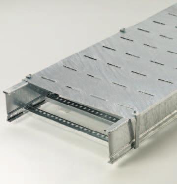
2 Tray onstruction I-Beam Side Rails ooper B-Line s I-Beam siderails are an integral part of all 2, 3, 4, and 5 series ladder trays. The I-Beam is ideal for ladder tray, providing more strength than a -shaped siderail. Benefits of the I-beam design include: Enlarged top flange for stiffness Bend in sidewall to lock in rung position and provide additional material for strong welds Bottom surface to provide strong support for rungs Welding ooper B-Line welds are designed for strong construction. 4-point welding systems provide multiple points of connection Welders are certified to merican Welding Standards (WS) D1.1 & D1.2 Rungs are welded to both sidewall and bottom of I-Beam siderail Splicing ooper B-Line splices create a sturdy connection between ladder sections. Splices fit between the top and bottom flanges of the I-Beam siderail for a secure connection Eight (8) sets of hardware allow for easy installation and provide excellent rigidity ll fitting bends and turns have a 3 (152mm) tangent (straight section) at each end to provide a good place for attaching splice plates leat ttachment ooper B-Line s slotted rungs make it easy to fasten down cables using cable cleats. Slot sized for maximum 3 /8 or M10 hardware Specially designed rung profiles for strength More details on cable cleats is available in the able leats brochure or on the website at 2
3 Table of ontents ooper Industries, recognized for its leadership, expertise and innovation in the global industrial market, opened its newest manufacturing facility located in Dammam, Kingdom of Saudi rabia, in Located less than 20 kilometers from Saudi ramco headquarters in Dhahran, the ooper facility offers an extensive line of electrical products, components and engineering services for the region's growing oil and gas market. The new 50,000- square foot facility has been delegated as an ramco-approved facility for ooper B-Line produced products, which involved passing the Saudi oil company's strenuous quality management assessments and strict Saudisation provisions. In conjunction with the facility's ramco-approved status, ooper has pledged to maintain at least a 50% Saudi-employed workforce at the plant, a promise that will pay dividends in the local job market. The new facility will significantly reduce ooper's delivery lead times for product orders and specification configurations in the G. ooper B-Line offers the region a broad line of cable tray products, including aluminum, steel and fiberglass cable ladder, as well as its cable tray and Flextray wire basket products. The facility also offers best-in-class specification engineering services, which will provide pre- and post-sale engineering and technical support to customers throughout the region. ooper B-Line's presence in this area represents a continuation of the company's investment in the global oil and gas industry, adding the G to its global coverage area that already includes offices in Korea, London, algary and Houston. The initial ooper product lines were chosen to support target end markets in a region that relies heavily on the oil and gas industry. However, ooper plans to broaden its product offering to support additional markets throughout the G in the coming years. Table of ontents able Ladder onstruction Light Duty Steel able Ladder Light Duty Steel able Ladders Light Duty Steel able Ladder ccessories Light Duty Steel able Ladder overs & over ccessories Light Duty Steel able Ladder Fittings Heavy Duty Steel able Ladder Heavy Duty Steel able Ladders Heavy Duty Steel able Ladder ccessories Heavy Duty Steel able Ladder overs & over ccessories Heavy Duty Steel able Ladder Fittings able leats Stainless Steel able Ladder Stainless Steel able Ladders Stainless Steel able Ladder ccessories Stainless Steel able Ladder overs & over ccessories Stainless Steel able Ladder Fittings able leats able Ladder Fittings Heavy Duty Steel & Stainless Steel able Ladder Fittings Technical Data Metric onversion harts
4 able Ladder onstruction Steel able Tray, Series 2, 3, 4 & 5 -- the Side Rails Roll formed for extra strength 2. Enlarged top flange for stiffness 3. Structural grade traceable steel 4. Rung top lock 5. Rung bottom rest Our I-Beam -- the most efficient structural shape Side rails are stamped with: ompany Name Part Number Material Heat Trace Number -- the Splices -- provide system integrity The Splices -- the engineered connection: Special high strength eleven gauge steel Eight bolt connection for required strength Finish and hardware options -- Hot Dip Galvanized fter Fabrication (HDGF) -- providing system integrity STM 123/S Type I In plant post-dip inspection and deburr STM F Grade 3 Splice hardware exceeds NEM requirements. STM 123 overs available - system compatibility -- Pre-Galvanized- Hot Dip Mill Galvanized -- providing system integrity STM 653SS Gr.33 G90/ S Type II nti-corrosive silicon bronze welds eliminate cosmetic painting -- our reliable time-tested products. system that works. 200 lb. oncentrated Load- side rail and rungs Splice integrity - 3" fitting tangents 4

5 Light Duty Steel able Ladder able Ladders able Ladder ccessories able Ladder Fittings
 4\" (101mm) NEM VE 1 Loading Depth - Series 156 ctual Side Rail Height - 4.188 (106mm) ctual Loading Depth = 3.")
6 Light Duty Steel able Ladder 3" (76mm) NEM VE 1 Loading Depth - Series 148 ctual Side Rail Height (92mm) ctual Loading Depth = 3.077" (78mm) 4" (101mm) NEM VE 1 Loading Depth - Series 156 ctual Side Rail Height (106mm) ctual Loading Depth = 3.628" (92mm) 5" (127mm) NEM VE 1 Loading Depth - Series 166 ctual Side Rail Height (132mm) ctual Loading Depth = 4.628" (117mm) Straight Section Part Numbering Example: 156 P 09 SL Series Material Rung Spacing Rung Type Width Length P = Pre-Galvanized 06 = 6" (152) SL - Slotted 06 = 6" (152) = 12 ft. (3.7m) 148 Steel 09 = 9" (228) 09 = 9" (228) ➁ 120 = 10 ft. (3.0m) G = Hot Dip 12 = 12" (305) 12 = 12" (305) = 12 ft. (3.7m) 156 Galvanized 18 = 18" (457) ➁ 120 = 10 ft. (3.0m) fter Fabrication 24 = 24" (609) = 12 ft. (3.7m) 166 Steel 30 = 30" (762) ➁ 120 = 10 ft. (3.0m) 36 = 36" (914) 1Primary Length. ➁Secondary Length. R ung Spa cin g Overall Width (Width + 1 / 8 (3.2mm)) ll dimensions in parentheses are in millimeters unless otherwise specified. 6
7 Light Duty Steel able Ladder Series 148 Dimensional & Loading Information Values are based on simple beam tests per NEM VE 1 on 36" (914mm) wide cable tray with rungs spaced on 12" (305mm) centers. The published load safety factor is 1.5. To convert 1.5 safety factor to 2.0, multiply the published load by To obtain mid-span deflection, multiply a load by the deflection multiplier. able tray must be supported on spans shorter than or equal to the length of the cable tray being installed. B-Line Side Rail NEM, S & UL Span Load Deflection Design Factors Series Dimensions lassifications ft meters lbs/ft kg/m Multiplier for Two Rails gauge NEM: 12, * 304* rea=0.51 in 2 rea=3.29 cm 2 S: 1-3m Sx=0.48 in 3 Sx=7.87 cm 3 UL ross-sectional Ix=0.89 in 4 Ix=37.04 cm 4 rea: 0.40 in *When using 12" (305mm) rung spacing load capacity is limited to 195 lbs/ft ( kg/m) for 36" (914mm) tray width. When cable trays are used in continuous spans, the deflection of the cable tray is reduced by as much as 50%. Design factors: Ix = Moment of Inertia, Sx = Section Modulus. Series 156 Dimensional & Loading Information Values are based on simple beam tests per NEM VE 1 on 36" (914mm) wide cable tray with rungs spaced on 12" (305mm) centers. able trays will support without collapse a 200 lb. (90.7 kg) concentrated load over and above the published loads. The published load safety factor is 1.5. To convert 1.5 safety factor to 2.0, multiply the published load by To obtain mid-span deflection, multiply a load by the deflection multiplier. able tray must be supported on spans shorter than or equal to the length of the cable tray being installed. B-Line Side Rail NEM, S & UL Span Load Deflection Design Factors Series Dimensions lassifications ft meters lbs/ft kg/m Multiplier for Two Rails gauge NEM: 12B, * 452* rea=0.68 in 2 rea=4.39 cm 2 S: 1-3m Sx=0.724 in 3 Sx=11.86 cm 3 UL ross-sectional Ix=1.517 in 4 Ix=63.14 cm 4 rea: 0.40 in *When using 12" (305mm) rung spacing, load capacity is limited to 234 lbs/ft ( kg/m) for 30" (762mm) tray width and 195 lbs/ft ( kg/m) for 36" (914mm) tray width. When trays are used in continuous spans, the deflection of the tray is reduced by as much as 50%. Design factors: Ix = Moment of Inertia, Sx = Section Modulus. Series 166 Dimensional & Loading Information Values are based on simple beam tests per NEM VE 1 on 36" (914mm) wide cable tray with rungs spaced on 12" (305mm) centers. able trays will support without collapse a 200 lb. (90.7 kg) concentrated load over and above the published loads. The published load safety factor is 1.5. To convert 1.5 safety factor to 2.0, multiply the published load by To obtain mid-span deflection, multiply a load by the deflection multiplier. able tray must be supported on spans shorter than or equal to the length of the cable tray being installed. B-Line Side Rail NEM, S & UL Span Load Deflection Design Factors Series Dimensions lassifications ft meters lbs/ft kg/m Multiplier for Two Rails gauge NEM: 12B, * 458* rea=0.77 in 2 rea=4.97 cm 2 S: 1-3m Sx=0.93 in 3 Sx=15.24 cm 3 UL ross-sectional Ix=2.40 in 4 Ix=99.90 cm 4 rea: 0.70 in *When using 12" (305mm) rung spacing, load capacity is limited to 234 lbs/ft ( kg/m) for 30" (762mm) tray width and 195 lbs/ft ( kg/m) for 36" (914mm) tray width. When trays are used in continuous spans, the deflection of the tray is reduced by as much as 50%. Design factors: Ix = Moment of Inertia, Sx = Section Modulus. ll dimensions in parentheses are in millimeters unless otherwise specified. 7
8 Light Duty Steel able Ladder ccessories Standard (L-Shaped) Splice Plates One pair including hardware provided with each section. Furnished in pairs with hardware. Prepackaged in pairs in a plastic bag, with hardware. 4-hole pattern L-shaped splice plates. L-shaped lay-in design. (*) Insert ZN or G Expansion (L-Shaped) Splice Plates Expansion plates allow for one inch expansion or contraction of the cable tray, or where expansion joints occur in the supporting structure. Bonding Jumpers are required. Order Separately. L-shaped lay-in design. Furnished in pairs with hardware. (*) Insert ZN or G Tray Series atalog No. Tray Series atalog No (*) (*) (*) (*) (*) (*)-4016 Universal Splice Plates Used to splice to existing cable tray systems. Furnished in pairs with hardware. (*) Insert P or G Step Down Splice Plates These splice plates are offered for connecting cable tray sections having side rails of different heights. Furnished in pairs with hardware. (*) Insert ZN or G Tray Series atalog No (*) /2 Tray Series atalog No (*) / (*) /2 156 to 148 9(*) to 156 or 148 9(*)-8045 Vertical djustable Splice Plates These plates provide for changes in elevation that do not conform to standard vertical fittings. Furnished in pairs with hardware. (*) Insert ZN or G Requires supports within 24 on both sides, per NEM VE 2. Tray Series atalog No (*) (*) (*)-8025 Horizontal djustable Splice Plates Offered to adjust a cable tray run for changes in direction in a horizontal plane that do not conform to standard horizontal fittings. Furnished in pairs with hardware. New design bonding jumpers not required. (*) Insert ZN or G (X) Insert 4 for series 148 or for series for series 176 9(*)-803(X) Splices only atalog able Tray Tray No. End ut Width 'L' 9(*)-803(X) Mitered Thru 36" (914) N/ 9(*)-803(X)-12 Not mitered Thru 12" (305) 16" (406) 9(*)-803(X)-36 Not mitered Thru 36" (914) 41" (1041) 9(*)-803(X)-12 or 9(*)-803(X)-36 One pair splice plates with extensions. L L Requires supports within 24 (609mm) on both sides, per NEM VE 2. ll dimensions in parentheses are in millimeters unless otherwise specified. 8
9 Light Duty Steel able Ladder ccessories Offset Reducing Splice Plate This plate is used for joining cable trays having different widths. When used in pairs they form a straight reduction; when used singly with a standard splice plate they form an offset reduction. Furnished as one plate with hardware. ( ) Insert reduction (*) Insert P or G Tray to Box Splice Plates Used to attach the end of a cable tray run to a distribution box or control panel. Furnished in pairs with hardware. (*) Insert P or G Tray Series atalog No (*)-8064-( ) 156 9(*)-8064-( ) 166 9(*)-8065-( ) Tray Series atalog No (*) (*) (*)-8055 Frame Type Box onnector Designed to attach the end of a cable tray run to a distribution cabinet or control center to help reinforce the box at the point of entry. Furnished with tray connection hardware. ( ) Insert tray width (*) Insert P or G Blind End This plate forms a closure for a dead end cable tray. Furnished as one plate with hardware. ( ) Insert tray width (*) Insert P or G Tray Series atalog No (*)-8074-( ) 156 9(*)-8074-( ) 166 9(*)-8075-( ) Tray Series atalog No (*)-8084-( ) 156 9(*)-8084-( ) 166 9(*)-8085-( ) Tray Hardware Pre-Galvanized Tray Hardware onduit to Tray daptor For easy attachment of conduit terminating at a cable tray. Use on aluminum or steel cable trays. atalog No. RNB 3 /8"-16 x 3 /4" Znplt Ribbed Neck arriage Bolt STM 307 Grade atalog No. SFHN 3 /8"-16 Znplt Serrated Flange Hex Nut STM 563 Grade Finish: Zinc Plated STM B633, S1 Hot Dip Galvanized Tray Hardware atalog No. RNB 3 /8"-16 x 3 /4" Z Ribbed Neck arriage Bolt hromium Zinc STM F atalog No. SFHN 3 /8"-16 Z Serrated Flange Hex Nut hromium Zinc STM F atalog No. onduit Size in. mm 9G /2, 3 /4 1/2, 3 /4 15, 20 9G , 1 1 /4 1, 1 1 /4 25, 32 9G /2, /2, 2 40, 50 9G /2, /2, 3 65, 80 9G /2, /2, 4 90, 100 ll dimensions in parentheses are in millimeters unless otherwise specified. 9
10 Light Duty Steel able Ladder ccessories able Tray lamp/guide Features a no-twist design. Has four times the strength of the traditional design. Each side is labeled to ensure proper installation. Furnished in pairs, with or without hardware. 9ZN-1208 shown. Installed as a clamp. Patent # RE35479 atalog No. Without With Overall Hardware Hardware Hardware Length Size Finish in. mm 9ZN ZN-1204NB 1 1 /2 38 1/4" Znplt 9ZN ZN-1208NB 2 1 /4 57 3/8" Znplt 1 1 /2" (39mm) 2 1 /4" (57mm) 9ZN-1204 shown. Installed as a guide. Ground lamp Mechanically attaches grounding cables to cable tray. Hardware included. (*) Insert ZN or SS4 Grounding lamp B-Line able Tray is UL classified as to its suitability as an equipment grounding conductor. If a separate conductor for additional grounding capability is desired, B-Line offers this clamp for bolting the conductor at least once to each tray section. ccepts #6 WG to 250 MM. atalog No. able Size 9(*)-2351 #1 thru 2/0 9(*) /0 thru 250 MM Bonding Jumper Use at each expansion splice and where the cable tray is not mechanically/electrically continuous to ground. Sold individually. Hardware included. See table 392.7(B)(2) on page 67 for amperage ratings required to match the UL cross-sectional area of the tray. 600 amp rating. Bonding jumper is 16" (406) long. atalog No. ross-sectional rea mpacity 99-N1 1.5 Square inches 600 atalog No. Material Item Tin Plated luminum Grounding lamp Hanger Rod lamp For 1 /2" TR. Furnished in pairs. Order TR and hex nuts separately. Two piece "J"-hanger design. 9ZN-1113 has 275 lbs. (1.22kN)/pair safety factor 3 capacity. 9ZN-532(X) has 1500 lbs. (6.67kN)/pair capacity safety factor 3. Tray Series atalog No ZN ZN ZN-5325 Threaded Rod (TR) & Rod oupling Loading based on safety factor 5. Standard Finish: Zinc plated See B-Line Strut Systems atalog for other sizes and finishes. Loading atalog vailable oupling Size lbs. (kn) No. Lengths at. No. 3/ (3.24) TR 3 /8 x Length 36" (914), 72" (1829), 120" (3048), 144" (3657) B655-3 /8 1/ (6.00) TR 1 /2 x Length 36" (914), 72" (1829), 120" (3048), 144" (3657) B655-1 /2 ll dimensions in parentheses are in millimeters unless otherwise specified. 10
11 Light Duty Steel able Ladder ccessories Ladder Drop-Out This special designed, easy to install drop-out provides a 4" (101.6 mm) radius to protect cables exiting the cable tray from damage. ttaches to a ladder rung. Hardware included. (*) Insert P or G ( ) Insert tray width atalog No. 9(*)-1104T-( ) Barriers Straight Section Standard length: 120" (3 m) 144" (12 ft.). Order catalog number based on loading depth. Furnished with four #10 x 1 /2" plated selfdrilling screws and a splice. (*) Insert P or G H Horizontal Bend Horizontal Bend Barriers are flexible in order to conform to any horizontal fitting radius. ut to length. Order catalog number based on loading depth. Furnished with three #10 x 1 /2" zinc plated self-drilling screws and a Barrier Strip Splice. Standard length is 72" (1828mm) (6 ft.), sold individually. (*) Insert P or G Tray H Series atalog No. in. mm (*)-Length (*)-Length Length = 144 for 12' or 120 for 10' Tray H Series atalog No. in. mm (*)-90HBFL (*)-90HBFL H (*)-Length (*)-90HBFL Vertical Bend Barriers Vertical Bend Barriers are preformed to conform to a specific vertical fitting. Furnished with three #10 x 1 /2" plated self-drilling screws and a Barrier Strip Splice. (*) Insert P or G (**) Insert 30, 45, 60 or 90 for degrees ( ) Insert 12 or 24 for radius Inside Bend (VI) Barrier Strip Splice Plastic splice holds adjoining barrier strips in straight alignment. H H Tray atalog No. H Series Inside Bend Outside Bend in. mm (*)-(**)VI( ) 72(*)-(**)VO( ) (*)-(**)VI( ) 737(*)-(**)VO( ) (*)-(**)VI( ) 747(*)-(**)VO( ) Outside Bend (VO) atalog No ll dimensions in parentheses are in millimeters unless otherwise specified. 11
12 Light Duty Steel able Ladder ccessories antilever Bracket Finishes available: ZN, GRN, or HDG Safety Load Factor 2.5 antilever Bracket Finishes available: ZN, GRN, or HDG Safety Load Factor 2.5 atalog Uniform Tray No. Load Width lbs kn in. mm in. mm B & & B B atalog Uniform Tray No. Load Width lbs kn in. mm in. mm B B B antilever Bracket Finishes available: ZN, GRN, HDG, SS4. or SS6 Safety Load Factor 2.5 antilever Bracket Finishes available: ZN, GRN, HDG, or SS4 Safety Load Factor 2.5 atalog Uniform Tray No. Load Width lbs kn in. mm in. mm B & & B B atalog Uniform Tray No. Load Width lbs kn in. mm in. mm B B B Underfloor Support (U-Bolts not included) Finish available: ZN Safety Load Factor 2.5. U-Bolt Size Fits Pipe O.D. B501-3 / B B / B / B B / Order properly sized U-Bolts separately. atalog No. Uniform Load Tray Width '' lbs kn in. mm in. mm B409UF & & B409UF & & Beam lamp Finishes available: ZN or HDG Sold in pieces with hardware. Design load when used in pairs. Safety Load Factor 5.0 atalog No. Design Load* '' lbs kn in. mm B /8 86 B ll dimensions in parentheses are in millimeters unless otherwise specified. 12
13 overs Solid covers should be used when maximum enclosure of the cables is desired and no accumulation of heat is expected. Ventilated covers provide an overhead cable shield yet allow heat to escape. ooper B-Line recommends that covers on vertical cable tray runs to a height of 6 ft. (1.83 m) to 8 ft. (2.44 m) above the floor to isolate both cables and personnel. Flanged covers have a.30 in. (7.6 mm) flange. over clamps are not included with the cover and must be ordered separately. Light Duty Steel able Ladder overs Solid Flanged overs Part Numbering Prefix Example: 80 1 P Ventilated Flanged over Type Detail Material Material Thickness Tray Width Item Description 80 = Solid 1 = Flanged P = Pre-Galvanized 20 = 20 Ga. Steel for 06 = 6" (152) For Straight Section over: 81 = Ventilated G = HDGF Pre-Galvanized 09 = 9" (228) Pre-Galvanized Only: 18 = 18 Ga. Steel for 12 = 12" (305) 144 = 12 ft. (3.66 m) HDGF 18 = 18" (457) 120 = 10 ft. (3.05 m) 24 = 24" (609) Pre-Galvanized & HDGF 30 = 30" (762) 72 = 6 ft. (1.83 m) 36 = 36" (914) 60 = 5 ft. (1.52 m) For fitting covers: Insert suffix of fitting overs 30" and 36" wide have reinforcing ridges. to be covered. See example below. Example of atalog Number for Fitting over: Vertical Bend over Prefix Suffix 80 1 P VO 24-4* * Required for VO fittings only. Side Rail* Height Radius Fitting ngle Width Material Thickness Material Detail over Type Quantity of Standard over lamps Required Straight Section 60" (1.52m) or 72" (1.83m)... 4 pcs. Straight Section 120" (3.05m) or 144" (3.66m) 6 pcs. Horizontal/Vertical Bends pcs. Tees pcs. rosses pcs. Note: When using the Heavy Duty over lamp, only one-half the number of clamps stated above is required. over Joint Strip Used to join covers Plastic ( ) Insert tray width at. No ( ) Standard over lamp Sold per piece For indoor service only Tray atalog No. Series Znplt HDGF 148 9ZN G ZN G ZN G-9015 ombination Hold Down & over lamp Sold per piece For indoor service only Heavy Duty over lamp ( ) Insert tray width Tray atalog No. Series Znplt/Pre-Galv. HDGF 148 9ZN G P G P G-9053 Tray atalog No. Series Pre-Galv. HDGF 148 9P-( ) G-( ) P-( ) G-( ) P-( ) G-( )-9054 ll dimensions in parentheses are in millimeters unless otherwise specified. 13
14 Light Duty Steel able Ladder Fittings Fittings engineered with 3" (76mm) tangents for splicing integrity. Fittings Part Numbering Prefix Example: 1 4 P SL HB 24 (9" rung spacing is standard) Series 1 Height 4 = = = 166 Material P = Pre-Galvanized G = HDGF Rung Type SL = Slotted Rung Width 06 = 6" (152) 09 = 9" (228) 12 = 12" (305) 18 = 18" (457) 24 = 24" (609) 30 = 30" (762) 36 = 36" (914) ngle 30 = = = = 90 Type HB = Horizontal Bend HT = Horizontal Tee HX = Horizontal ross VI = Vertical Inside Bend VO = Vertical Outside Bend LR = Left Reducer RR = Right Reducer SR = Straight Reducer Radius 12 = 12" (305) 24 = 24" (609) ll dimensions in parentheses are in millimeters unless otherwise specified. 14
15 Light Duty Steel able Ladder Fittings Horizontal Bends (HB) 1 pair splice plates with hardware included. 90 Horizontal Bend 60 Horizontal Bend 45 Horizontal Bend 30 Horizontal Bend B R 3" (76) 90 HB B R 3" (76) 60 HB B R 3" (76) 45 HB B R 3" (76) 30 HB Bend Tray 90 Horizontal Bend 60 Horizontal Bend Radius Width Dimensions Dimensions R atalog No. B atalog No. B in. mm in. mm in. mm in. mm in. mm in. mm in. mm in. mm (Pre)-06-90HB (Pre)-06-60HB / / / (Pre)-09-90HB / / /2 495 (Pre)-09-60HB / / / (Pre)-12-90HB (Pre)-12-60HB / / / (Pre)-18-90HB (Pre)-18-60HB / / / (Pre)-24-90HB (Pre)-24-60HB / / / (Pre)-30-90HB (Pre)-30-60HB / / / (Pre)-36-90HB (Pre)-36-60HB / / / (Pre)-06-90HB (Pre)-06-60HB / / / (Pre)-09-90HB / / /2 800 (Pre)-09-60HB / / / (Pre)-12-90HB (Pre)-12-60HB / / / (Pre)-18-90HB (Pre)-18-60HB / / / (Pre)-24-90HB (Pre)-24-60HB / / / (Pre)-30-90HB (Pre)-30-60HB / / / (Pre)-36-90HB (Pre)-36-60HB / / / Horizontal Bend 30 Horizontal Bend (Pre)-06-45HB / / / (Pre)-06-30HB / / (Pre)-09-45HB / / / (Pre)-09-30HB / / / (Pre)-12-45HB / / / (Pre)-12-30HB / / / (Pre)-18-45HB / / (Pre)-18-30HB / / / (Pre)-24-45HB / / / (Pre)-24-30HB / / / (Pre)-30-45HB / / (Pre)-30-30HB / / / (Pre)-36-45HB / / / (Pre)-36-30HB / / / (Pre)-06-45HB / / (Pre)-06-30HB / / / (Pre)-09-45HB / / / (Pre)-09-30HB / / / (Pre)-12-45HB / / / (Pre)-12-30HB / / / (Pre)-18-45HB / / / (Pre)-18-30HB / / / (Pre)-24-45HB / / / (Pre)-24-30HB / / / (Pre)-30-45HB / / /8 486 (Pre)-30-30HB / / / (Pre)-36-45HB / / /8 518 (Pre)-36-30HB / / /4 362 (Pre) See page 14 for catalog number prefix. ll dimensions in parentheses are millimeters unless otherwise specified. Width dimensions are to inside wall. Manufacturing tolerances apply to all dimensions. 15
16 Light Duty Steel able Ladder Fittings Horizontal Tee (HT) 2 pair splice plates with hardware included. Bend Tray Horizontal Tee Radius Width Dimensions R atalog No. B in. mm in. mm in. mm in. mm (Prefix)-06-HT (Prefix)-09-HT / (Prefix)-12-HT (Prefix)-18-HT (Prefix)-24-HT (Prefix)-30-HT (Prefix)-36-HT (Prefix)-06-HT (Prefix)-09-HT / (Prefix)-12-HT (Prefix)-18-HT (Prefix)-24-HT (Prefix)-30-HT (Prefix)-36-HT B R 3" (76) HT W (Prefix) See page 14 for catalog number prefix. Horizontal ross (HX) 3 pair splice plates with hardware included. Bend Horizontal ross Radius Tray Dimensions R Width atalog No. B in. mm in. mm in. mm in. mm (Prefix)-06-HX (Prefix)-09-HX / (Prefix)-12-HX (Prefix)-18-HX (Prefix)-24-HX (Prefix)-30-HX (Prefix)-36-HX (Prefix)-06-HX (Prefix)-09-HX / (Prefix)-12-HX (Prefix)-18-HX (Prefix)-24-HX (Prefix)-30-HX (Prefix)-36-HX B R 3" (76) HX W (Prefix) See page 14 for catalog number prefix. ll dimensions in parentheses are millimeters unless otherwise specified. Width dimensions are to inside wall. Manufacturing tolerances apply to all dimensions. 16
17 Light Duty Steel able Ladder Fittings Reducers (LR, SR, RR) 1 pair splice plates with hardware included. Reducer Part Numbering 14P RR 18 Width 2 Fitting Width 1 Prefix Left Reducer Straight Reducer Right Reducer W 2 LR W 2 SR W 2 RR W 1 W 1 W 1 Tray Width Left Hand Reducer Straight Reducer Right Hand Reducer W 1 W 2 atalog No. atalog No. atalog No. in. mm in. mm in. mm in. mm in. mm (Prefix)-09-LR /4 248 (Prefix)-09-SR /8 225 (Prefix)-09-RR / (Prefix)-12-LR /2 292 (Prefix)-12-SR /4 248 (Prefix)-12-RR / (Prefix)-12-LR /4 248 (Prefix)-12-SR /8 225 (Prefix)-12-RR / (Prefix)-18-LR / (Prefix)-18-SR /2 292 (Prefix)-18-RR / (Prefix)-18-LR / (Prefix)-18-SR /8 270 (Prefix)-18-RR / (Prefix)-18-LR /2 292 (Prefix)-18-SR /4 248 (Prefix)-18-RR / (Prefix)-24-LR /8 467 (Prefix)-24-SR / (Prefix)-24-RR / (Prefix)-24-LR / (Prefix)-24-SR /8 314 (Prefix)-24-RR / (Prefix)-24-LR / (Prefix)-24-SR /2 292 (Prefix)-24-RR / (Prefix)-24-LR /2 292 (Prefix)-24-SR /4 248 (Prefix)-24-RR / (Prefix)-30-LR /8 555 (Prefix)-30-SR / (Prefix)-30-RR / (Prefix)-30-LR /8 511 (Prefix)-30-SR / (Prefix)-30-RR / (Prefix)-30-LR /8 462 (Prefix)-30-SR / (Prefix)-30-RR / (Prefix)-30-LR / (Prefix)-30-SR /2 292 (Prefix)-30-RR / (Prefix)-30-LR /2 292 (Prefix)-30-SR /4 248 (Prefix)-30-RR / (Prefix)-36-LR / (Prefix)-36-SR / (Prefix)-36-RR / (Prefix)-36-LR / (Prefix)-36-SR / (Prefix)-36-RR / (Prefix)-36-LR /8 555 (Prefix)-36-SR / (Prefix)-36-RR / (Prefix)-36-LR /8 462 (Prefix)-36-SR / (Prefix)-36-RR / (Prefix)-36-LR / (Prefix)-36-SR /2 292 (Prefix)-36-RR / (Prefix)-36-LR /2 292 (Prefix)-36-SR /4 248 (Prefix)-36-RR /2 292 (Prefix) See page 14 for catalog number prefix. ll dimensions in parentheses are millimeters unless otherwise specified. Width dimensions are to inside wall. Manufacturing tolerances apply to all dimensions. 17
18 Light Duty Steel able Ladder Fittings Vertical Bend 90 (VO, VI) 1 pair splice plates with hardware included. 90 VI 90 VO B 3" (76) R R 3" (76) B 90 Vertical Inside 90 Vertical Outside VO Dimensions ll Series 1 Bend Radius R B 90 Vertical Bend 12" 15" 15" 15" (305) (381) (381) (381) 24" 27" 27" 27" (609) (686) (686) (686) 90 Vertical Inside Bend Bend VI Dimensions Radius Series 14 Steel Series 15 Steel Series 16 Steel R Width atalog No. in. mm in. mm B B B (Pre)-06-90(*) (Pre)-09-90(*) (Pre)-12-90(*) /16" 18 7 /16" 18 7 /16" 19 3 /16" 19 3 /16" 19 3 /16" 20 3 /16" 20 3 /16" 20 3 /16" (Pre)-18-90(*) (Pre)-24-90(*)12 (468) (468) (468) (487) (487) (487) (513) (513) (513) (Pre)-30-90(*) (Pre)-36-90(*) (Pre)-06-90(*) (Pre)-09-90(*) (Pre)-12-90(*) /16" 30 7 /16" 30 7 /16" 31 3 /16" 31 3 /16" 31 3 /16" 32 3 /16" 32 3 /16" 32 3 /16" (Pre)-18-90(*) (Pre)-24-90(*)24 (773) (773) (773) (792) (792) (792) (817) (817) (817) (Pre)-30-90(*) (Pre)-36-90(*)24 (Pre) See page 14 for catalog number prefix. (*) = Insert VI for Vertical Inside Bend. Insert VO for Vertical Outside Bend. ll dimensions in parentheses are millimeters unless otherwise specified. Manufacturing tolerances apply to all dimensions. 18
19 Light Duty Steel able Ladder Fittings Vertical Bend 60 (VO, VI) 1 pair splice plates with hardware included. 60 VI 60 VO B 3" (76) R R 3" (76) B 60 Vertical Inside 60 Vertical Outside VO Dimensions ll Series 1 Bend Radius R B 60 Vertical Bend 12" 14 7 /8" 8 5 /8" 9 15 /16" (305) (378) (219) (252) 24" 25 5 /16" 14 5 /8" 16 7 /8" (609) (643) (371) (428) 60 Vertical Inside Bend Bend Tray VI Dimensions Radius atalog Width Series 14 Steel Series 15 Steel Series 16 Steel R No. in. mm in. mm B B B (Pre)-06-60(*) (Pre)-09-60(*) (Pre)-12-60(*) /16" 10 7 /16" 12" 18 1 /2" /16" 12 3 /8" 19 3 /8" 11 3 /16" /16" (Pre)-18-60(*) (Pre)-24-60(*)12 (459) (265) (305) (470) (271) (314) (492) (284) (328) (Pre)-30-60(*) (Pre)-36-60(*) (Pre)-06-60(*) (Pre)-09-60(*) (Pre)-12-60(*) /16" 16 7 /16" /16" /16" /16" 19 1 /4" 29 3 /4" 17 3 /16" 19 7 /8" (Pre)-18-60(*) (Pre)-24-60(*)24 (722) (417) (481) (735) (424) (489) (755) (436) (505) (Pre)-30-60(*) (Pre)-36-60(*)24 (Pre) See page 14 for catalog number prefix. (*) = Insert VI for Vertical Inside Bend. Insert VO for Vertical Outside Bend. ll dimensions in parentheses are millimeters unless otherwise specified. Manufacturing tolerances apply to all dimensions. 19
20 Light Duty Steel able Ladder Fittings Vertical Bend 45 (VO, VI) 1 pair splice plates with hardware included. B 3" (76) R 45 VI 45 Vertical Inside 45 Vertical Outside R 3" (76) 45 VO B VO Dimensions ll Series 1 Bend Radius R B 45 Vertical Bend 12" 13 5 /8" 5 5 /8" 8" (305) (346) (143) (203) 24" 22 1 /16" 9 1 /8" /16" (609) (560) (232) (328) 45 Vertical Inside Bend Bend Tray atalog VI Dimensions Radius Width No. Series 14 Steel Series 15 Steel Series 16 Steel R in. mm in. mm B B B (Pre)-06-45(*) (Pre)-09-45(*) (Pre)-12-45(*) /16" 6 11 /16" 9 1 /2" 16 9 /16" 6 7 /8" 9 11 /16" 17 1 /4" 7 3 /16" 10 1 /8" (Pre)-18-45(*) (Pre)-24-45(*)12 (411) (170) (241) (420) (174) (246 (438) (182) (257) (Pre)-30-45(*) (Pre)-36-45(*) (Pre)-06-45(*) (Pre)-09-45(*) (Pre)-12-45(*) /16" 10 3 /16" 14 7 /16" 25 1 /16" 10 3 /8" /16" 25 3 /4" /16" 15 1 /16" (Pre)-18-45(*) (Pre)-24-45(*)24 (627) (259) (367) (662) (263) (373) (654) (271) (382) (Pre)-30-45(*) (Pre)-36-45(*)24 (Pre) See page 14 for catalog number prefix. (*) = Insert VI for Vertical Inside Bend. Insert VO for Vertical Outside Bend. ll dimensions in parentheses are millimeters unless otherwise specified. Manufacturing tolerances apply to all dimensions. 20
 able Ladders.......................... 22-27 able Ladder ccessories.......... 28-38 able Ladder Fittings................. 50-62 21")
21 Heavy Duty Steel able Ladder able Ladder wit h Slotte d Rung (shown with a lternating slot orie nta tion) able Ladder wit h Slotte d Rung (shown with c ontinuous sl ot down - also avai lable with c ontinuous slot up) able Ladders able Ladder ccessories able Ladder Fittings
22 Heavy Duty Steel able Ladder 4" (101mm) NEM VE 1 Loading Depth 5" (127mm) Side Rail Height Straight Section Part Numbering Example: 356 P 09 SL DN Series Material Rung Rung Rung Width Length Spacing Type Orientation P = Pre- Galv. 06 = 6" (152) SL - Slotted Blank - Slots 06 = 6" (152) = 20 ft. (6.1m) Steel = 9" (228) alternate 09 = 9" (228) ➁ 144 = 12 ft. (3.7m) G = Hot Dip 12 = 12" (305) up & down 12 = 12" (305) = 20 ft. (6.1m) Galvanized (as shown below) = 18" (457) ➁ 288 = 24 ft. (7.3m) fter Fabrication DN - ontinuous 24 = 24" (609) Steel slot down 1Primary Length. 30 = 30" (762) ➁Secondary Length. UP - ontinuous 36 = 36" (914) slot up Ru ng Sp acing Width (Insi de ) Overall Wi dth (Wi dt h /8 (35mm)) ll dimensions in parentheses are in millimeters unless otherwise specified. 22
23 Heavy Duty Steel able Ladder 4" (101mm) NEM VE 1 Loading Depth 5" (127mm) Side Rail Height Values are based on simple beam tests per NEM VE 1 on 36" (914mm) wide cable tray with rungs spaced on 12" (305mm) centers. able trays will support without collapse a 200 lb. (90.7 kg) concentrated load over and above published loads. Published load safety factor is 1.5. To convert 1.5 safety factor to 2.0, multiply published load by To obtain mid-span deflection, multiply a load by the deflection multiplier. able tray must be supported on spans shorter than or equal to the length of the cable tray being installed. Individual rungs will support without collapse a 200 lb. (90.7 kg) concentrated load applied at the mid-span of the rung, over and above the NEM rated cable load with a 1.5 safety factor for highlighted NEM spans and loads. B-Line Side Rail NEM, S & UL Span Load Deflection Design Factors Series Dimensions lassifications ft meters lbs/ft kg/m Multiplier for Two Rails 1.50 NEM: 20, S: D1-6m rea=1.00 in 2 rea=6.45 cm Sx=1.31 in 3 Sx=21.47 cm 3 UL ross-sectional Ix=3.73 in 4 Ix= cm 4 rea: 0.70 in gauge B-Line Side Rail NEM, S & UL Span Load Deflection Design Factors Series Dimensions lassifications ft meters lbs/ft kg/m Multiplier for Two Rails 1.50 NEM: S: E-6m rea=1.34 in 2 rea=8.65 cm Sx=1.75 in 3 Sx=28.68 cm 3 UL ross-sectional Ix=4.96 in 4 Ix= cm 4 rea: 1.00 in gauge When cable trays are used in continuous spans, the deflection of the cable tray is reduced by as much as 50%. Design factors: Ix = Moment of Inertia, Sx = Section Modulus. ll dimensions in parentheses are in millimeters unless otherwise specified. 23
24 Heavy Duty Steel able Ladder 5" (127mm) NEM VE 1 Loading Depth 6" (152mm) Side Rail Height Straight Section Part Numbering Example: 366 P 09 SL DN Series Material Rung Rung Rung Width Length Spacing Type Orientation P = Pre- Galv. 06 = 6" (152) SL - Slotted Blank - Slots 06 = 6" (152) = 20 ft. (6.1m) 366 Steel 09 = 9" (228) alternate 09 = 9" (228) ➁ 144 = 12 ft. (3.7m) G = Hot Dip 12 = 12" (305) up & down 12 = 12" (305) = 20 ft. (6.1m) Galvanized (as shown below) = 18" (457) ➁ 288 = 24 ft. (7.3m) fter Fabrication DN - ontinuous 24 = 24" (609) Steel slot down 30 = 30" (762) UP - ontinuous 36 = 36" (914) slot up 1Primary Length. ➁Secondary Length. Ru ng Spacing Width (Insi de ) Overall Wi dth (Wi dt h /8 (35mm)) ll dimensions in parentheses are in millimeters unless otherwise specified. 24
25 Heavy Duty Steel able Ladder 5" (127mm) NEM VE 1 Loading Depth 6" (152mm) Side Rail Height Values are based on simple beam tests per NEM VE 1 on 36" (914mm) wide cable tray with rungs spaced on 12" (305mm) centers. able trays will support without collapse a 200 lb. (90.7 kg) concentrated load over and above published loads. Published load safety factor is 1.5. To convert 1.5 safety factor to 2.0, multiply published load by To obtain mid-span deflection, multiply a load by the deflection multiplier. able tray must be supported on spans shorter than or equal to the length of the cable tray being installed. Individual rungs will support without collapse a 200 lb. (90.7 kg) concentrated load applied at the mid-span of the rung, over and above the NEM rated cable load with a 1.5 safety factor for highlighted NEM spans and loads. B-Line Side Rail NEM, S & UL Span Load Deflection Design Factors Series Dimensions lassifications ft meters lbs/ft kg/m Multiplier for Two Rails 1.50 NEM: 20B, S: E-6m rea=1.11 in 2 rea=7.16 cm Sx=1.71 in 3 Sx=28.02 cm 3 UL ross-sectional Ix=5.74 in 4 Ix= cm 4 rea: 1.00 in gauge B-Line Side Rail NEM, S & UL Span Load Deflection Design Factors Series Dimensions lassifications ft meters lbs/ft kg/m Multiplier for Two Rails 1.50 NEM: S: E-6m rea=1.49 in 2 rea=9.61 cm Sx=2.28 in 3 Sx=37.36 cm 3 UL ross-sectional Ix=7.65 in 4 Ix= cm 4 rea: 1.00 in gauge When cable trays are used in continuous spans, the deflection of the cable tray is reduced by as much as 50%. Design factors: Ix = Moment of Inertia, Sx = Section Modulus. ll dimensions in parentheses are in millimeters unless otherwise specified. 25
 SL - Slotted Blank - Slots 06 = 6\" (152) 1 240 = 20 ft. (6.1m) 476 Steel 09 = 9\" (228) alternate 09 = 9\" (228) ➁ 288 = 24 ft. (7.")
26 Heavy Duty Steel able Ladder 6" (152mm) NEM VE 1 Loading Depth 7" (178mm) Side Rail Height Straight Section Part Numbering Example: 476 P 09 SL DN Series Material Rung Rung Rung Width Length Spacing Type Orientation P = Pre- Galv. 06 = 6" (152) SL - Slotted Blank - Slots 06 = 6" (152) = 20 ft. (6.1m) 476 Steel 09 = 9" (228) alternate 09 = 9" (228) ➁ 288 = 24 ft. (7.3m) G = Hot Dip 12 = 12" (305) up & down 12 = 12" (305) = 20 ft. (6.1m) Galvanized (as shown below) = 18" (457) ➁ 288 = 24 ft. (7.3m) fter Fabrication DN - ontinuous 24 = 24" (609) Steel slot down 30 = 30" (762) UP - ontinuous 36 = 36" (914) slot up 1Primary Length. ➁Secondary Length. Run g Sp acin g Width (Insi de ) Ove ra ll Width (Width /8 (35mm)) ll dimensions in parentheses are in millimeters unless otherwise specified. 26
27 Heavy Duty Steel able Ladder 6" (152mm) NEM VE 1 Loading Depth 7" (178mm) Side Rail Height Values are based on simple beam tests per NEM VE 1 on 36" (914mm) wide cable tray with rungs spaced on 12" (305mm) centers. able trays will support without collapse a 200 lb. (90.7 kg) concentrated load over and above published loads. Published load safety factor is 1.5. To convert 1.5 safety factor to 2.0, multiply published load by To obtain mid-span deflection, multiply a load by the deflection multiplier. able tray must be supported on spans shorter than or equal to the length of the cable tray being installed. Individual rungs will support without collapse a 200 lb. (90.7 kg) concentrated load applied at the mid-span of the rung, over and above the NEM rated cable load with a 1.5 safety factor for highlighted NEM spans and loads. B-Line Side Rail NEM, S & UL Span Load Deflection Design Factors Series Dimensions lassifications ft meters lbs/ft kg/m Multiplier for Two Rails 1.50 NEM: 20B, S: D1-6m rea=1.22 in 2 rea=7.87 cm Sx=2.14 in 3 Sx=35.07 cm 3 UL ross-sectional Ix=8.30 in 4 Ix= cm 4 rea: 1.00 in gauge B-Line Side Rail NEM, S & UL Span Load Deflection Design Factors Series Dimensions lassifications ft meters lbs/ft kg/m Multiplier for Two Rails 1.50 NEM: S: E-6m rea=1.64 in 2 rea=10.58 cm Sx=2.87 in 3 Sx=47.03 cm 3 UL ross-sectional Ix=11.10 in 4 Ix= cm 4 rea: 1.50 in gauge When cable trays are used in continuous spans, the deflection of the cable tray is reduced by as much as 50%. Design factors: Ix = Moment of Inertia, Sx = Section Modulus. ll dimensions in parentheses are in millimeters unless otherwise specified. 27
28 Heavy Duty Steel able Ladder ccessories Splice Plates Standard 8-hole pattern for all steel splice plates. Furnished in pairs with hardware. One pair including hardware provided with straight section. Boxed in pairs with hardware. (*) Insert ZN or G Expansion Splice Plates Expansion plates allow for one inch expansion or contraction of the cable tray, or where expansion joints occur in the support structure. Furnished in pairs with hardware. Bonding Jumpers are required on each siderail. Order Separately. (*) Insert ZN or G atalog No. Height in. mm 9(*) (*) (*) atalog No. Height in. mm 9(*) (*) (*) Universal Splice Plates Used to splice to existing cable tray systems. Furnished in pairs with hardware. (*) Insert ZN or G Step Down Splice Plates These splice plates are offered for connecting cable tray sections having side rails of different heights. Furnished in pairs with hardware. (*) Insert ZN or G atalog No. Height in. mm 9(*) / (*) / (*) / atalog No. Height in. mm 9(*) to to 127 9(*) to to 127 9(*) to to 152 Vertical djustable Splice Plates These plates provide for changes in elevation that do not conform to standard vertical fittings. Furnished in pairs with hardware. Bonding Jumpers not required. (*) Insert G or P Horizontal djustable Splice Plates Offered to adjust a cable tray run for changes in direction in a horizontal plane that do not conform to standard horizontal fittings. Furnished in pairs with hardware. New design bonding jumpers not required. (*) Insert ZN or G (X) Insert 5, 6 or 7 for side rail height. 9(*)-803(X)-12 or 9(*)-803(X)-36 One pair splice plates with extensions. L L 9(*)-803(X) Splice only atalog No. Height in. mm 9(*) (*) (*) Requires supports within 24 (609mm) on both sides, per NEM VE 2. atalog able Tray Tray No. End ut Width 'L' 9(*)-803(X) Mitered Thru 36" (914) N/ 9(*)-803(X)-12 Not mitered Thru 12" (305) 16" (406) 9(*)-803(X)-36 Not mitered Thru 36" (914) 41" (1041) Requires supports within 24 (609mm) on both sides, per NEM VE 2. ll dimensions in parentheses are in millimeters unless otherwise specified. 28
29 Heavy Duty Steel able Ladder ccessories ross onnector Bracket For field connecting crossing section. Furnished in pairs with 3 /8" hardware. (*) Insert ZN or G Offset Reducing Splice Plate This plate is used for joining cable trays having different widths. When used in pairs they form a straight reduction; when used singly with a standard splice plate, they form an offset reduction. Furnished as one plate with hardware. ( ) Insert reduction (*) Insert G or P atalog No. 9(*)-1240 atalog No. Height in. mm 9(*)-8065-( ) (*)-8066-( ) (*)-8067-( ) Tray to Box Splice Plates Used to attach the end of a cable tray run to a distribution box or control panel. Furnished in pairs with hardware. (*) Insert G or P Frame Type Box onnector Designed to attach the end of a cable tray run to a distribution cabinet or control center to help reinforce the box at the point of entry. Furnished with tray connection hardware. (*) Insert ZN or G ( ) Insert tray width Blind End This plate forms a closure for a dead end cable tray. Furnished as one plate with hardware. (*) Insert G or P ( ) Insert tray width atalog No. Height in. mm 9(*) (*) (*) atalog No. Height in. mm 9(*)-8075-( ) (*)-8076-( ) (*)-8077-( ) atalog No. Height in. mm 9(*)-8085-( ) (*)-8086-( ) (*)-8087-( ) Tray Hardware Pre-Galvanized Tray Hardware onduit to Tray daptor For easy attachment of conduit terminating at a cable tray. Use on aluminum or steel cable trays. atalog No. RNB 3 /8"-16 x 3 /4" Znplt Ribbed Neck ZN arriage Bolt STM 307 Grade atalog No. SFHN 3 /8"-16 Znplt Serrated Flange Hex Nut ZN STM 563 Grade Finish: Zinc Plated STM B633, S1 Hot Dip Galvanized Tray Hardware Standard: atalog No. RNB 3 /8"-16 x 3 /4" Z Ribbed Neck arriage Bolt STM F Grade 3 hromium Zinc atalog No. SFHN 3 /8"-16 Z Serrated Flange Hex Nut STM F Grade hromium Zinc Optional: atalog No. RNB 3 /8"-16 x 3 /4" SS6 ISI Stainless Steel atalog No. SFHN 3 /8"-16 SS6 ISI 316 Stainless Steel Example: 9G-8004SS6 atalog No. onduit Size in. mm 9G /2, 3 /4 1/2, 3 /4 15, 20 9G , 1 1 /4 1, 1 1 /4 25, 32 9G /2, /2, 2 40, 50 9G /2, /2, 3 65, 80 9G /2, /2, 4 90, 100 ll dimensions in parentheses are in millimeters unless otherwise specified. Steel I-Beam 29
30 Heavy Duty Steel able Ladder ccessories Ladder Drop-Out Specially-designed Ladder Drop-Outs provide a rounded surface with 4" (101 mm) radius to protect cable as it exits from the cable tray, preventing damage to insulation. The drop-out will attach to any desired rung. (*) Insert P or G ( ) Insert tray width atalog No. 9(*)-1104-( ) Barriers Straight Section Standard length: 120" (3.05m) 144" (3.66m). Order catalog number based on loading depth. Furnished with four #10 x 1 /2" plated selfdrilling screws and a splice. (*) Insert P or G H Horizontal Bend Horizontal Bend Barriers are flexible in order to conform to any horizontal fitting radius. ut to length. Order catalog number based on loading depth. Furnished with three #10 x 1 /2" zinc plated self-drilling screws and a Barrier Strip Splice. Standard length is 72" (1828mm) (6 ft.), sold individually. (*) Insert P or G H atalog Side Rail Loading No. Height Depth 'H' in. mm in. mm 74(*)-Length (*)-Length (*)-Length Length = 144 for 12 (3.66m) or 120 for 10' (3.05m) atalog Side Rail Loading No. Height Depth 'H' in. mm in. mm 74(*)-90HBFL (*)-90HBFL (*)-90HBFL Vertical Bend Barriers Vertical Bend Barriers are preformed to conform to a specific vertical fitting. Furnished with three #10 x 1 /2" plated self-drilling screws and a Barrier Strip Splice. (*) Insert P or G H (**) Insert 30, 45, 60 or 90 for degrees ( ) Insert 12, 24, 36 or 48 for radius Barrier Strip lip Zinc plated steel barrier clip fastens to either aluminum or steel ladder rung. Furnished with one #10 x 1 /2" zinc plated self-drilling screw. H Inside Bend (VI) atalog No. 9ZN-9002 Outside Bend (VO) Inside Bend Outside Bend Side Rail Loading atalog No. atalog No. Height Depth 'H' in. mm in. mm 74(*)-(**)VI( ) 74(*)-(**)VO( ) (*)-(**)VI( ) 75(*)-(**)VO( ) (*)-(**)VI( ) 76(*)-(**)VO( ) Barrier Strip Splice Plastic splice holds adjoining barrier strips in straight alignment. atalog No ll dimensions in parentheses are in millimeters unless otherwise specified. 30
31 Heavy Duty Steel able Ladder ccessories Threaded Rod Loading based on safety factor 5. Standard Finish: Zinc Plated. See B-Line Strut Systems atalog for other sizes and finishes. Bonding Jumper Use at each expansion splice and where the cable tray is not mechanically/electrically continuous to ground. Sold individually. Hardware included. See table 392.7(B)(2) on page 67 for amperage ratings required to match the UL cross-sectional area of the tray. See tray loading chart for UL cross-sectional area. Bonding jumper is 16" (406) long. Loading atalog vailable Lengths Size lbs. (kn) No. in. (mm) 3/ (3.25) TR 3 /8 x Length 36" (914), 72" (1829), 120" (3048), 144" (3657) 1/ (6.00) TR 1 /2 x Length 36" (914), 72" (1829), 120" (3048), 144" (3657) atalog No. ross-sectional rea mpacity 99-N1 1.5 Square inches 600 Rod ouplers Loading based on safety factor 5. Standard Finish: Zinc Plated. See B-Line Strut Systems atalog for other sizes and finishes. Grounding lamp ooper B-Line able Tray is UL classified as to its suitability as an equipment grounding conductor. If a separate conductor for additional grounding capability is desired, B-Line offers this clamp for bolting the conductor at least once to each cable tray section. ccepts #6 WG to 250 MM. oupling Size at. No. 3/8-16 B655-3 /8 1/2-13 B655-1 /2 Item Material atalog No. Grounding lamp Tin Plated luminum Ground lamp Mechanically attaches grounding cables to cable tray. Hardware included. (*) Insert ZN or SS4 Hanger Rod lamp For 1 /2" TR. Furnished in pairs. Order TR and hex nuts separately. Two-piece J -hanger design. (*) Insert ZN or G 1500 lbs./pair capacity safety factor 3. atalog No. able Size 9(*)-2351 #1 thru 2/0 9(*) /0 thru 250 MM atalog No. Rail Height in. mm 9(*) (*) (*) ll dimensions in parentheses are in millimeters unless otherwise specified. 31
32 Heavy Duty Steel able Ladder ccessories able Tray lamp/guide Features a no-twist design. Has four times the strength of the traditional design. Each side is labeled to ensure proper installation. Furnished in pairs, with or without hardware. 9ZN-1208 shown. Installed as a clamp. 9ZN-1204 shown. Installed as a guide. 1 1 /2" (39mm) atalog No. Without With Overall Hardware Hardware Hardware Length Size Finish in. mm 9ZN ZN-1204NB 1 1 /2 38 1/4" Znplt 9ZN ZN-1208NB 2 1 /4 57 3/8" Znplt /4 57 1/2" lum. 9G /4 57 1/2" HDGF 9SS /4 57 1/2" 316SS 9ZN /4 57 1/2" Znplt Patent # RE /4" (57mm) Note: For heavy duty or vertical applications see 9(*)-1241 or 9(*)-1242 page 35. When installing this device as an expansion guide on the outside flange of Steel Side Rail, use the atalog No. B202 Square Washer in order to properly elevate the guide. able Tray Guide Expansion guide for single or double cable tray runs. Guide allows for longitudinal movement of the cable tray. No field drilling of support I-beam or channel is required. Guides are required on both sides of cable tray to prevent lateral movement - can be placed on either the inside or outside flange of cable tray. Guides are sold in pieces - two guides are required per tray. Maximum flange thickness 1 1 /8" (28.58 mm). atalog No. Finish 9ZN-1249 Zinc Plated 9G-1249 HDGF Nylon Pad Use for friction reduction. Hardness: Shore D80. Low friction coefficient. UV resistant (black). Excellent weatherability. UL-94HB. 1/8" (3mm) Neoprene Roll Used for material isolation. 1 /8" x 2" x 20' roll. Hardness: Shore 60. Good weatherability. 3" (76mm) 6" (152mm) atalog No. 99-NY36 atalog No. 99-NP240 ll dimensions in parentheses are in millimeters unless otherwise specified. 32
33 Heavy Duty Steel able Ladder ccessories Trapeze Support Kit ooper B-Line's trapeze kits provide the components required for a single trapeze support in one package. These kits are available in pre-galvanized steel with zinc-plated hardware or hot dip galvanized steel with 316 stainless steel hardware. The SH channel provides the convenience of pre-punched slots, which eliminate the need for field drilling. The illustrated hardware is sealed in a plastic bag and boxed with the channel,which is pre-cut to the appropriate length as shown in the chart. Designed for use with 1 /2" threaded rod. Order rod separately. atalog Tray hannel Uniform No. Width Length Load in. mm in. mm lbs kn 9P SH( ) P SH( ) P SH( ) P SH( ) P SH( ) P SH( ) P SH( ) P SH( ) ( ) Insert 3 /8 for 3 /8" threaded rod hardware. Safety factor of 3.0 on all loads. (2) 1/2" x 7/8" Hex Head ap Screw (2) 9ZN-1205 Hold-Down Guide lamp (2) N525WO hannel Nut (4) 1/2" Hex Nut (4) B202 Square Washer (1) B22 hannel cut to the required length Heavy Duty Trapeze Support Kit ooper B-Line's trapeze kits provide the components required for a single trapeze support in one package. These kits are available in Dura-Green epoxy coated steel with zinc-plated hardware or hot dip galvanized steel with 316 stainless steel hardware. The SH channel provides the convenience of pre-punched slots, which eliminates the need for field drilling. The illustrated hardware is sealed in a plastic bag and boxed with the channel, which is pre-cut to the appropriate length as shown in the chart. Designed for use with 1 /2" threaded rod. Order rod separately. (2) 1/2" x 7/8" Hex Head ap Screw atalog Tray hannel Uniform No. Width Length Load in. mm in. mm lbs kn 9(*) SH (*) SH (*) SH (*) SH (*) SH (*) SH (*) SH (*) SH (*) Insert GRN or G Safety factor of 3.0 on all loads. (2) 9ZN-1205 Hold-Down Guide lamp (2) N525WO hannel Nut (4) 1/2" Hex Nut (4) B202 Square Washer (1) hannel cut to the required length Trapeze Hardware Kit atalog No. (plastic bagged) 9ZN /2 9G /2 1 pr. 9ZN pr. 9G HH Screw 1 /2 x 7 /8 ZN 2 HH Screw 1 /2 x 7 /8 SS6 2 N525 WO ZN 2 N525 WO SS6 4 B202 ZN 1 /2" sq washer 4 B202 HDG 1 /2" sq washer 4 HN 1 /2 ZN 4 HN 1 /2 SS6 ll dimensions in parentheses are in millimeters unless otherwise specified. 33
34 Heavy Duty Steel able Ladder ccessories antilever Bracket Finishes available: ZN, GRN, or HDG Safety Load Factor 2.5 antilever Bracket Finishes available: ZN, GRN, or HDG Safety Load Factor 2.5 atalog Uniform Tray No. Load Width lbs kn in. mm in. mm B & & B B atalog Uniform Tray No. Load Width lbs kn in. mm in. mm B B B B antilever Bracket Finishes available: ZN, GRN, or HDG Safety Load Factor 2.5 antilever Bracket Finishes available: ZN, GRN, or HDG Safety Load Factor 2.5 atalog Uniform Tray No. Load Width lbs kn in. mm in. mm atalog Uniform Tray No. Load Width lbs kn in. mm in. mm B & & B B B & & B B B B B ll dimensions in parentheses are in millimeters unless otherwise specified. 34
35 Heavy Duty Steel able Ladder ccessories Underfloor Support (U-Bolts not included) Finish available: ZN Safety Load Factor 2.5 Vertical Hanger Splice Plates (*) Insert ZN or G Design load is 1500 lbs/pair. Safety Factor of 2.5 Furnished in pairs with hardware. U-Bolt Size Fits Pipe O.D. B501-3 / B B / B / B B / Order properly sized U-Bolts separately. 7" (178mm) atalog Uniform Tray No. Load Width lbs kn in. mm in. mm B09UF & & B409UF & & atalog No. Outside '' able Tray Ht. in. mm 9(*) " (*) " (*) " Heavy Duty Hold-Down Bracket Design load is 2000 lbs/pair. Two bolt design. Sold in pairs. 3 /8" cable tray attachment hardware provided. 1 /2" support attachment hardware not provided. (*) Insert ZN or G Heavy Duty Hold-Down Bracket Design load is 4000 lbs/pair. Four bolt design. Sold in pairs. 3 /8" cable tray attachment hardware provided 1 /2" support attachment hardware not provided. (*) Insert ZN or G atalog No. 9(*)-1241 atalog No. 9(*)-1242 ll dimensions in parentheses are in millimeters unless otherwise specified. 35
36 Heavy Duty Steel able Ladder ccessories Beam lamp Finishes available: Insert ZN or HDG Sold in pieces. Beam lamp Finishes available: ZN, GRN, HDG, or SS4 Sold in pieces. Design load is 1200 lbs. (5.34kN) when used in pairs. Safety Load Factor 5.0 Order HHS and hannel Nuts separately. Beam lamp Finishes available: ZN, GRN, or HDG Sold in pieces. Design load when used in pairs. B212-3/8 = 600 lbs. (2.67kN) Safety Load Factor 5.0 Design load when used in pairs. Safety Load Factor 5.0 atalog Design Load* '' No. lbs kn in. mm B /8 86 B atalog No. B355 at. No. B212-1 /4 B212-3 /8 Design Load * 600 lbs kn 1000 lbs kn Max. Flange Thick 3/4" 19 mm 1 1 /8" 28.6 mm Mat'l. Thickness 1/4" 6.3 mm 3/8" 9.5 mm B305 Thru B308 & B321 Series Beam lamps Finishes available: ZN or HDG Setscrew included. Safety Load Factor 5.0 D E B B312 nchor Strap Finish available: ZN For a maximum beam thickness of 3 /4" (19). For thicker beams, step up one flange width size. F T at. Rod Design Load No. Size B D E F T lbs kn B305 3/8"-16 3/8" /16" 7/8" 1 1 /8" 2 1 /2" 11 Ga B306 3/8"-16 1/2" /16" 7/8" 1 1 /8" 2 1 /2" 7 Ga B307 1/2"-13 1/2" /16" 7/8" 1 1 /8" 2 1 /2" 7 Ga B308 1/2"-13 1/2" /16" 7/8" 1 1 /8" 2 1 /2" 1/4" B /8"-16 1/2" /16" 1 11 /16" 1 5 /8" 3 1 /4" 1/4" B /2"-13 1/2" /16" 1 11 /16" 1 5 /8" 3 1 /4" 1/4" at. No. Flange Width B312-6 Up to 6" B " - 9" B " - 12" Beam lamp atalog For Flange Width Wt./ No. in. mm lbs kg B750-J4 3"- 6" B750-J6 5"- 9" B750-J9 8"- 12" B750-J12 11"- 15" Finish available: ZN Design Load 500 lbs. (2.22 kn) Safety Load Factor 5.0 Recommended torque: 'J'-Hook Nut 125 In.-Lbs. (14.1 kn/m) Maximum flange thickness of 3 /4" (19) Material: 7 Gauge (4.6) 1 1 /2" (38.1) 1/2"-13 Rod & Hex Nut Sold Separately 1 7 /8" (47.6) J-Hook & Hex Nut Included Beam lamp J-Hook atalog '' Thread Length 'TL' Wt./ No. in. mm in. mm lbs kg 1/2"-13 Threads B700-J4 8 1 /2" " B700-J /2" " B700-J /4" " B700-J /2" " Finish available: ZN Hex Nut included. TL ll dimensions in parentheses are in millimeters unless otherwise specified. 36
37 overs Heavy Duty Steel able Ladder overs Solid Flanged Ventilated Flanged Peaked Flanged full range of covers is available for straight sections and fittings. Solid covers should be used when maximum enclosure of the cable is desired and no accumulation of heat is expected. Ventilated covers provide an overhead cable shield yet allow heat to escape. ooper B-Line recommends that covers be placed on vertical cable tray runs to a height of 6 ft. (1.83 m) to 8 ft. (2.44 m) above the floor to isolate both cables and personnel. Flanged covers have a 1 /2 in. (13 mm) flange. over clamps are not included with the cover and must be ordered separately. ll peaked covers are flanged. Standard peaked covers have 1 /2 (13 mm) peak. Steel over Part Numbering Prefix Example: 80 2 P over Type Detail Material Material Thickness Tray Width Item Description 80 = Solid 2= Flanged Steel (ll fittings) P = Pre-Galvanized 20 = 20 Pre-Galv For Straight Section overs: 81 = Ventilated 3= Flanged Steel (ll straight G = HDGF 18 = 18 HDGF 82 = Peaked sections) overs 30" (762) and 36" (914) wide have reinforcing ridges. 06 = 6" (152) 09 = 9" (228) 12 = 12" (305) 18 = 18" (457) 24 = 24" (609) 30 = 30" (762) 36 = 36" (914) Pre-Galvanized Only: 144 = 12 ft. (3.66 m) 120 = 10 ft. (3.05 m) Pre-Galvanized & HDGF 72 = 6 ft. (1.83 m) 60 = 5 ft. (1.52 m) For fitting covers: Insert suffix of fitting to be covered. See example below. Examples of atalog Numbers for Fitting overs: Horizontal Bend over Prefix Suffix 80 2 P HB 24 Radius Fitting ngle Width Material Thickness Material Detail over Type Vertical Bend over Prefix Suffix 80 2 G VO 24-4* Side Rail* Height Radius Fitting ngle Width Material Thickness Material Detail over Type * Required for VO fittings only ll dimensions in parentheses are in millimeters unless otherwise specified. 37
 Insert P or G For indoor service only. Raised over lamp For indoor service only. For use with flanged covers only. Specify gap of 1\", 2\", 3\" or 4\" Tray Side Rail atalog Type Height No. in. mm 5 127 9(*)-9015 Steel 6 152 9(*)-9016 7 178 9(*)-9017 Heavy Duty over lamp Recommended for outdoor service.")
-( )-9054 6 152 9(*)-( )-9064 7 178 9(*)-( )-9074 Tray Side Rail atalog Type Height No. in.")
 or 72\" (1.83m)...4 pcs. Straight Section 120\" (3.05m) or 144\" (3.66m)...6 pcs. Horizontal/Vertical Bends...4 pcs. Tees...6 pcs. rosses...8 pcs.")
38 Heavy Duty Steel able Ladder over ccessories Standard over lamp For indoor service only. Sold per piece. (*) Insert ZN or G ombination over and Hold-Down lamp Sold per piece. (*) Insert P or G For indoor service only. Raised over lamp For indoor service only. For use with flanged covers only. Specify gap of 1", 2", 3" or 4" Tray Side Rail atalog Type Height No. in. mm (*)-9015 Steel (*) (*)-9017 Heavy Duty over lamp Recommended for outdoor service. (*) Insert P or G ( ) Insert tray width dd P to atalog No. for 1 /2" (13mm) peaked cover clamp. Side Rail atalog Height No. in. mm (*)-( ) (*)-( ) (*)-( )-9074 Tray Side Rail atalog Type Height No. in. mm (*)-9053 Steel (*) (*)-9073 Peaked over lamp Tray Type Series 3 & 4 Steel Straight Section ll Steel Fittings Quantity of Standard over lamps Required Straight Section 60" (1.52m) or 72" (1.83m)...4 pcs. Straight Section 120" (3.05m) or 144" (3.66m)...6 pcs. Horizontal/Vertical Bends...4 pcs. Tees...6 pcs. rosses...8 pcs. Note: When using the Heavy Duty over lamp, only one-half the number of clamps stated above is required. over Joint Strip Used to join covers Plastic ( ) Insert tray width atalog No. 9ZN ZN-910 atalog No ( ) able leats (Refer to able leats Brochure) Trefoil able leats able leats ll dimensions in parentheses are in millimeters unless otherwise specified. 38
 able Ladders.......................... 40-41 able Ladder ccessories.......... 42-49 able Ladder Fittings................. 50-62 39")
39 Stainless Steel able Ladder a bl e La dder wi th Slotte d Rung (shown with alte rnati ng slot ori ent ation) a bl e La dder wi th Slotte d Rung (shown with conti nuous slot down - al so ava ilable with conti nu ous slot up) able Ladders able Ladder ccessories able Ladder Fittings
 4\" (101mm) NEM VE 1 Loading Depth - 5 (127mm) Side Rail Height - Series 358 ctual Loading Depth = 4.")
40 Stainless Steel able Ladder 3" (76mm) NEM VE 1 Loading Depth - 4 (101mm) Side Rail Height - Series 348 ctual Loading Depth = 3.13" (79mm) 4" (101mm) NEM VE 1 Loading Depth - 5 (127mm) Side Rail Height - Series 358 ctual Loading Depth = 4.13" (105mm) 5" (127mm) NEM VE 1 Loading Depth - 6 (152mm) Side Rail Height - Series 464 ctual Loading Depth = 5.11" (130mm) Straight Section Part Numbering Example: 358 SS6 09 SL DN Series Material Rung Rung Rung Width Length Spacing Type Orientation SS4 = = 6" (152) SL - Slotted Blank - Slots 06 = 6" (152) = 12 ft. (3.7m) Stainless Steel = 9" (228) alternate 09 = 9" (228) ➁ 120 = 10 ft. (3.0m) SS6 = = 12" (305) up & down 12 = 12" (305) = 12 ft. (3.7m) Stainless Steel (as shown below) 18 = 18" (457) ➁ 240 = 20 ft. (6.1m) 358 DN - ontinuous 24 = 24" (609) = 20 ft. (6.1m) slot down 30 = 30" (762) ➁ 288 = 24 ft. (7.3m) 464 UP - ontinuous 36 = 36" (914) 1Primary Length. slot up ➁Secondary Length. Run g Sp acin g Wi dth (Inside ) Overall Wi dth (Wi dt h /8 (35mm)) ll dimensions in parentheses are in millimeters unless otherwise specified. 40
41 Stainless Steel able Ladder Series 348 Dimensional & Loading Information Values are based on simple beam tests per NEM VE 1 on 36" (914mm) wide cable tray rungs spaced on 12" (305mm) centers. able trays will support without collapse a 200 lb. (90.7 kg) concentrated load over and above published loads. Published load safety factor is 1.5. To convert 1.5 safety factor to 2.0, multiply published load by To obtain mid-span deflection, multiply a load by the deflection multiplier. able tray must be supported on spans shorter than or equal to the length of the cable being installed. B-Line Side Rail NEM, S & UL Span Load Deflection Design Factors Series Dimensions lassifications ft meters lbs/ft kg/m Multiplier for Two Rails 1.50 NEM: 16, S: 1-3m rea=0.79 in 2 rea=4.77 cm Sx=0.79 in 3 Sx=12.95 cm SS 3 UL ross-sectional Ix=1.85 in 4 Ix=77.00 cm 4 rea: 0.40 in gauge When cable trays are used in continuous spans, the deflection of the cable tray is reduced by as much as 50%. Design factors: Ix = Moment of Inertia, Sx = Section Modulus. Insert 4 for 304 stainless steel or 6 for 316 stainless steel. Series 358 Dimensional & Loading Information Values are based on simple beam tests per NEM VE 1 on 36" (914mm) wide cable tray rungs spaced on 12" (305mm) centers. able trays will support without collapse a 200 lb. (90.7 kg) concentrated load over and above published loads. Published load safety factor is 1.5. To convert 1.5 safety factor to 2.0, multiply published load by To obtain mid-span deflection, multiply a load by the deflection multiplier. able tray must be supported on spans shorter than or equal to the length of the cable being installed. B-Line Side Rail NEM, S & UL Span Load Deflection Design Factors Series Dimensions lassifications ft meters lbs/ft kg/m Multiplier for Two Rails 1.50 NEM: 20, 16B S: 89 kg /m-6.1m rea=0.83 in 2 rea=5.35 cm Sx=1.09 in 3 Sx=17.86 cm SS 3 UL ross-sectional Ix=3.10 in 4 Ix= cm 4 rea: 0.70 in gauge When cable trays are used in continuous spans, the deflection of the cable tray is reduced by as much as 50%. Design factors: Ix = Moment of Inertia, Sx = Section Modulus. Insert 4 for 304 stainless steel or 6 for 316 stainless steel. Series 464 Dimensional & Loading Information Values are based on simple beam tests per NEM VE 1 on 36" (914mm) wide cable tray rungs spaced on 12" (305mm) centers. able trays will support without collapse a 200 lb. (90.7 kg) concentrated load over and above published loads. Published load safety factor is 1.5. To convert 1.5 safety factor to 2.0, multiply published load by To obtain mid-span deflection, multiply a load by the deflection multiplier. able tray must be supported on spans shorter than or equal to the length of the cable being installed. B-Line Side Rail NEM, S & UL Span Load Deflection Design Factors Series Dimensions lassifications ft meters lbs/ft kg/m Multiplier for Two Rails 1.50 NEM: 20, S: D1-6m rea=1.49 in 2 rea=9.61 cm Sx=2.28 in 3 Sx=37.36 cm SS 3 UL ross-sectional Ix=7.65 in 4 Ix= cm 4 rea: 0.70 in gauge When cable trays are used in continuous spans, the deflection of the cable tray is reduced by as much as 50%. Design factors: Ix = Moment of Inertia, Sx = Section Modulus. Insert 4 for 304 stainless steel or 6 for 316 stainless steel. ll dimensions in parentheses are in millimeters unless otherwise specified. 41
42 Stainless Steel able Ladder ccessories Splice Plates Standard 8-hole pattern for all steel splice plates. Furnished in pairs with hardware. One pair including hardware provided with straight section. Boxed in pairs with hardware. (*) Insert SS4 or SS6 Expansion Splice Plates Expansion plates allow for one inch expansion or contraction of the cable tray, or where expansion joints occur in the support structure. Furnished in pairs with hardware. Bonding Jumpers are require on each siderail. Order Separately. (*) Insert SS4 or SS6 atalog No. Height in. mm 9(*) (*) (*) atalog No. Height in. mm 9(*) (*) (*) Universal Splice Plates Used to splice to existing cable tray systems. Furnished in pairs with hardware. (*) Insert SS4 or SS6 Step Down Splice Plates These splice plates are offered for connecting cable tray sections having side rails of different heights. Furnished in pairs with hardware. (*) Insert SS4 or SS6 atalog No. Height in. mm 9(*) / (*) / (*) / atalog No. Height in. mm 9(*) to to 101 9(*) to to 101 9(*) to to 127 Vertical djustable Splice Plates These plates provide for changes in elevation that do not conform to standard vertical fittings. Furnished in pairs with hardware. Bonding Jumpers not required. (*) Insert SS4 or SS6 Horizontal djustable Splice Plates Offered to adjust a cable tray run for changes in direction in a horizontal plane that do not conform to standard horizontal fittings. Furnished in pairs with hardware. New design bonding jumpers not required. (*) Insert SS4 or SS6 (X) Insert 4, 5, or 6 for side rail height. 9(*)-803(X)-12 or 9(*)-803(X)-36 One pair splice plates with extensions. L L 9(*)-803(X) Splice only atalog No. Height in. mm 9(*) (*) (*) Requires supports within 24 on both sides, per NEM VE 2. atalog able Tray Tray No. End ut Width 'L' 9(*)-803(X) Mitered Thru 36" N/ 9(*)-803(X)-12 Not mitered Thru 12" 16" 9(*)-803(X)-36 Not mitered Thru 36" 41" Requires supports within 24 on both sides, per NEM VE 2. ll dimensions in parentheses are in millimeters unless otherwise specified. 42
43 Stainless Steel able Ladder ccessories ross onnector Bracket For field connecting crossing section. Furnished in pairs with 3 /8" hardware. (*) Insert SS4 or SS6 Offset Reducing Splice Plate This plate is used for joining cable trays having different widths. When used in pairs they form a straight reduction; when used singly with a standard splice plate, they form an offset reduction. Furnished as one plate with hardware. ( ) Insert reduction (*) Insert SS4 or SS6 atalog No. 9(*)-1240 atalog No. Height in. mm 9(*)-8064-( ) (*)-8065-( ) (*)-8066-( ) Tray to Box Splice Plates Used to attach the end of a cable tray run to a distribution box or control panel. Furnished in pairs with hardware. (*) Insert SS4 or SS6 Frame Type Box onnector Designed to attach the end of a cable tray run to a distribution cabinet or control center to help reinforce the box at the point of entry. Furnished with tray connection hardware. (*) Insert SS4 or SS6 ( ) Insert tray width Blind End This plate forms a closure for a dead end cable tray. Furnished as one plate with hardware. (*) Insert SS4 or SS6 ( ) Insert tray width atalog No. Height in. mm 9(*) (*) (*) atalog No. Height in. mm 9(*)-8074-( ) (*)-8075-( ) (*)-8076-( ) atalog No. Height in. mm 9(*)-8084-( ) (*)-8085-( ) (*)-8086-( ) Type 316 Tray Hardware atalog No. RNB 3 /8"-16 x 3 /4" SS6 Ribbed Neck arriage Bolt Stainless Steel onduit to Tray daptor For easy attachment of conduit terminating at a cable tray. Use on aluminum or steel cable trays. atalog No. SFHN 3 /8"-16 SS6 Hex Nut Stainless Steel atalog No. onduit Size in. mm 9G /2, 3 /4 1/2, 3 /4 15, 20 9G , 1 1 /4 1, 1 1 /4 25, 32 9G /2, /2, 2 40, 50 9G /2, /2, 3 65, 80 9G /2, /2, 4 90, 100 Steel I-Beam ll dimensions in parentheses are in millimeters unless otherwise specified. 43
44 Stainless Steel able Ladder ccessories Ladder Drop-Out Specially-designed Ladder Drop-Outs provide a rounded surface with 4" (101 mm) radius to protect cable as it exits from the cable tray, preventing damage to insulation. The drop-out will attach to any desired rung. (*) Insert SS4 or SS6 ( ) Insert tray width atalog No. 9(*)-1104-( ) Barriers Straight Section Standard length: 120" (3.05m) 144" (3.66m). Order catalog number based on loading depth. Furnished with four #10 x 1 /2" plated selfdrilling screws and a splice. (*) Insert SS4 or SS6 H Horizontal Bend Horizontal Bend Barriers are flexible in order to conform to any horizontal fitting radius. ut to length. Order catalog number based on loading depth. Furnished with three #10 x 1 /2" zinc plated self-drilling screws and a Barrier Strip Splice. Standard length is 72" (1828mm) (6 ft.), sold individually. (*) Insert SS4 or SS6 H atalog Side Rail Loading No. Height Depth 'H' in. mm in. mm 73(*)-Length (*)-Length (*)-Length Length = 144 for 12 (3.66m) or 120 for 10' (3.05m) atalog Side Rail Loading No. Height Depth 'H' in. mm in. mm 73(*)-90HBFL (*)-90HBFL (*)-90HBFL Vertical Bend Barriers Vertical Bend Barriers are preformed to conform to a specific vertical fitting. Furnished with three #10 x 1 /2" plated self-drilling screws and a Barrier Strip Splice. (*) Insert SS4 or SS6 H (**) Insert 30, 45, 60 or 90 for degrees ( ) Insert 12, 24, 36 or 48 for radius Barrier Strip lip Zinc plated steel barrier clip fastens to either aluminum or steel ladder rung. Furnished with one #10 x 1 /2" SS4 plated self-drilling screw. (*) Insert SS4 or SS6 H Inside Bend (VI) atalog No. 9(*)-9002 Outside Bend (VO) Inside Bend Outside Bend Side Rail Loading atalog No. atalog No. Height Depth 'H' in. mm in. mm 73(*)-(**)VI( ) 73(*)-(**)VO( ) (*)-(**)VI( ) 74(*)-(**)VO( ) (*)-(**)VI( ) 75(*)-(**)VO( ) Barrier Strip Splice Plastic splice holds adjoining barrier strips in straight alignment. atalog No ll dimensions in parentheses are in millimeters unless otherwise specified. 44
45 Stainless Steel able Ladder ccessories able Tray lamp/guide Features a no-twist design. Has four times the strength of the traditional design. Each side is labeled to ensure proper installation. Furnished in pairs, with or without hardware. Vertical Tray Hanger (*) Insert SS4 or SS6 Design load 1500 lbs/pair (6.67kN). Safety Factor of 2.5 Furnished in pairs with hardware. 7" (178mm) Installed as a clamp. Installed as a guide. atalog No. 9SS Patent # RE35479 atalog No. Outside '' able Tray Ht. in. mm 9(*) " (*) " (*) " able Tray Guide Expansion guide for single or double cable tray runs. Guide allows for longitudinal movement of the cable tray. No field drilling of support I-beam or channel is required. Guides are required on both sides of cable tray to prevent lateral movement - can be placed on either the inside or outside flange of cable tray. Guides are sold in pieces - two guides are required per tray. Maximum flange thickness 1 1 /8" (28.58 mm). atalog No. Finish 9G-1249 HDGF Threaded Rod (TR) & Rod oupling Loading based on safety factor 5. Standard Finish: (*) Insert SS4 or SS6 See B-Line Strut Systems atalog for other sizes and finishes. Loading atalog vailable Size lbs No. Lengths 3/ TR 3 /8 x Length (*) 36", 72", 144" 1/ TR 1 /2 x Length (*) 36", 72", 144" oupling Size at No. 3/8-16 B655-3 /8 (*) 1/2-13 B655-1 /2 (*) Nylon Pad Use for friction reduction. Hardness: Shore D80. Low friction coefficient. UV resistant (black). Excellent weatherability. UL - 94HB. atalog No. Neoprene Roll Use for material isolation. 1 /8" x 2" x 20' roll. Hardness: Shore 60. Good weatherability. atalog No. 1/8" (3mm) 3" (76mm) 99-NY36 99-NP240 6" (152mm) ll dimensions in parentheses are in millimeters unless otherwise specified. 45
46 Stainless Steel able Ladder ccessories antilever Bracket Finishes available: SS4 or SS6 Safety Load Factor 2.5 antilever Bracket Finishes available: SS4 or SS6 Safety Load Factor 2.5 atalog Uniform Tray No. Load Width lbs kn in. mm in. mm B & & B B atalog Uniform Tray No. Load Width lbs kn in. mm in. mm B B B B antilever Bracket Finishes available: SS4 or SS6 Safety Load Factor 2.5 antilever Bracket Finishes available: SS4 or SS6 Safety Load Factor 2.5 atalog Uniform Tray No. Load Width lbs kn in. mm in. mm atalog Uniform Tray No. Load Width lbs kn in. mm in. mm B & & B B B & & B B B B B ll dimensions in parentheses are in millimeters unless otherwise specified. 46
47 Stainless Steel able Ladder ccessories Beam lamp Sold in pieces with hardware. (*) Insert SS4 or SS6 Sold in pieces. Design load when used in pairs. Safety Load Factor 5.0 Beam lamp Sold in pieces. Design load when used in pairs. Safety Load Factor Stainless Steel atalog Design Load '' No. lbs kn in. mm B441-22(*) /8 86 B441-22(*) atalog No. B212-1 /4SS4 B212-3 /8SS4 Design Load * 600 lbs kn 1000 lbs kn Max. Flange Thick 3 /4" 19 mm 1 1 /8" 28.6 mm Mat'l. Thickness 1 /4" 6.3 mm 3 /8" 9.5 mm Beam lamp Sold in pieces. Design load is 1200 lbs. (5.34kN) when use in pairs. Safety Load Factor 5.0 Order HHS and hannel Nuts separately. 304 Stainless Steel atalog No. B355 SS4 Heavy Duty Hold-Down Bracket Design load is 2000 lbs (8.9kN)/pair. Two bolt design. Sold in pairs. 3 /8" cable tray attachment hardware provided. 1 /2" support attachment hardware not provided. (*) Insert SS4 or SS6 Heavy Duty Hold-Down Bracket Design load is 4000 lbs (17.8kN)/pair. Four bolt design. Sold in pairs. 3 /8" cable tray attachment hardware provided 1 /2" support attachment hardware not provided. (*) Insert SS4 or SS6 atalog No. 9(*)-1241 atalog No. 9(*)-1242 ll dimensions in parentheses are in millimeters unless otherwise specified. 47
48 Stainless Steel able Ladder overs overs Solid Flanged Ventilated Flanged Peaked Flanged full range of covers is available for straight sections and fittings. Solid covers should be used when maximum enclosure of the cable is desired and no accumulation of heat is expected. Ventilated covers provide an overhead cable shield yet allow heat to escape. ooper B-Line recommends that covers be placed on vertical cable tray runs to a height of 6 ft. (1.83 m) to 8 ft. (2.44 m) above the floor to isolate both cables and personnel. Flanged covers have a 1 /2 (13 mm) flange. over clamps are not included with the cover and must be ordered separately. ll peaked covers are flanged. Standard peaked covers have 1 /2" (13 mm) peak. Stainless Steel over Part Numbering Prefix Example: 80 3 SS Material over Type Detail Material Thickness Tray Width Item Description 80 = Solid 81 = Ventilated 82 = Peaked 2= Flanged Stainless Steel (ll fittings) 3= Flanged Stainless Steel (ll straight sections) overs 30" and 36" wide have reinforcing ridges. SS4 = 304 Stainless Steel SS6 = 316 Stainless Steel 20 = 20 Ga. Stainless Steel 06 = 6" (152mm) 09 = 9" (228mm) 12 = 12" (305mm) 18 = 18" (457mm) 24 = 24" (609mm) 30 = 30" (762mm) 36 = 36" (914mm) For Straight Section over: 144 = 12 ft. (3.66 m) 120 = 10 ft. (3.05 m) 72 = 6 ft. (1.83 m) 60 = 5 ft. (1.52 m) For fitting covers: Insert suffix of fitting to be covered. See example below. Examples of atalog Numbers for Fitting overs: Horizontal Bend over Prefix Suffix 80 2 SS HB 24 Radius Fitting ngle Width Material Thickness Material Detail over Type Vertical Bend over Prefix Suffix 80 2 SS VO 24-4* * Required for VO fittings only Side Rail* Height Radius Fitting ngle Width Material Thickness Material Detail over Type ll dimensions in parentheses are in millimeters unless otherwise specified. 48
 Insert SS4 or SS6 For indoor service only. Raised over lamp For indoor service only. For use with flanged covers only.")
49 Stainless Steel able Ladder overs Standard over lamp For indoor service only. Sold per piece. 316 Stainless Steel ombination over and Hold-Down lamp Sold per piece. (*) Insert SS4 or SS6 For indoor service only. Raised over lamp For indoor service only. For use with flanged covers only. (*) Insert SS4 or SS6 Specify gap of 1" (25mm), 2" (52mm), 3" (76mm) or 4" (101mm) Tray Side Rail atalog Type Height No. in. mm Stainless Steel SS SS SS Heavy Duty over lamp Recommended for outdoor service. (*) Insert SS4 or SS6 ( ) Insert tray width dd P to atalog No. for 1 /2" (13mm) peaked cover clamp. Side Rail atalog Height No. in. mm (*)-( ) (*)-( ) (*)-( )-9064 Tray Side Rail atalog Type Height No. in. mm Stainless Steel (*) (*) (*)-9063 Peaked over lamp Tray Type Quantity of Standard over lamps Required Straight Section 60" (1.52m) or 72" (1.83m)...4 pcs. Straight Section 120" (3.05m) or 144" (3.66m)...6 pcs. Horizontal/Vertical Bends...4 pcs. Tees...6 pcs. rosses...8 pcs. Note: When using the Heavy Duty over lamp, only one-half the number of clamps stated above is required. over Joint Strip Used to join covers Plastic ( ) Insert tray width atalog No. Series 3 & 4 Steel Straight Section 9(*) ll Steel Fittings (lso Series 1 Steel 9(*)-910 Straight Sections) atalog No ( ) able leats (Refer to able leats Brochure) Trefoil able leats able leats ll dimensions in parentheses are in millimeters unless otherwise specified. 49
50 Steel & Stainless Steel able Ladder Fittings Fittings engineered with 3 tangents for splicing integrity. Fittings Part Numbering Prefix Example: 4 G - SLDN HB 24 (9" (228) rung spacing is standard) Side Rail Height 4 = 4" (101) 5 = 5" (127) 6 = 6" (152) 7 = 7" (178) Material G = HDGF P = Pre- Galvanized SS4 = 304 Stainless Steel SS6 = 316 Stainless Steel Rung Type & Orientation SL = Slotted Rung lternating up & down SLDN = Slotted Rung ontinuous slot down SLUP = Slotted Rung ontinuous slot up Width 06 = 6" (152) 09 = 9" (228) 12 = 12" (305) 18 = 18" (457) 24 = 24" (609) 30 = 30" (762) 36 = 36" (914) ngle 30 = = = = 90 Type HB = Horizontal Bend HT = Horizontal Tee HX = Horizontal ross VI = Vertical Inside Bend VO = Vertical Outside Bend VT = Vertical Tee VTU = Vertical Tee, Up HYR = Horizontal Wye, Right HYL = Horizontal Wye, Left SF = able Support Fitting LR = Left Reducer Fitting RR = Right Reducer Fitting SR = Straight Reducer Fitting Radius 12 = 12" (305) 24 = 24" (609) 36 = 36" (914) 48 = 48" (1219) Note: Horizontal crosses and tees 30" or wider, with a radius of 36" or larger, will be of two-piece construction. ll dimensions in parentheses are in millimeters unless otherwise specified. 50
51 Steel & Stainless Steel able Ladder Fittings Horizontal Bend (HB) 1 pair splice plates with hardware included. 90 Horizontal Bend 60 Horizontal Bend 90 HB 60 HB B R 3" (76) B R 3" (76) Bend Tray 90 Horizontal Bend 60 Horizontal Bend Radius Width Dimensions Dimensions R atalog No. B atalog No. B in. mm in. mm in. mm in. mm in. mm in. mm in. mm in. mm (Pre)-06-90HB (Pre)-06-60HB / / / (Pre)-09-90HB / / /2 495 (Pre)-09-60HB / / / (Pre)-12-90HB (Pre)-12-60HB / / / (Pre)-18-90HB (Pre)-18-60HB / / / (Pre)-24-90HB (Pre)-24-60HB / / / (Pre)-30-90HB (Pre)-30-60HB / / / (Pre)-36-90HB (Pre)-36-60HB / / / (Pre)-42-90HB (Pre)-42-60HB / / / (Pre)-06-90HB (Pre)-06-60HB / / / (Pre)-09-90HB / / /2 800 (Pre)-09-60HB / / / (Pre)-12-90HB (Pre)-12-60HB / / / (Pre)-18-90HB (Pre)-18-60HB / / / (Pre)-24-90HB (Pre)-24-60HB / / / (Pre)-30-90HB (Pre)-30-60HB / / / (Pre)-36-90HB (Pre)-36-60HB / / / (Pre)-42-90HB (Pre)-42-60HB / / (Pre)-06-90HB (Pre)-06-60HB / / / (Pre)-09-90HB / / / (Pre)-09-60HB / / / (Pre)-12-90HB (Pre)-12-60HB / / / (Pre)-18-90HB (Pre)-18-60HB / / (Pre)-24-90HB (Pre)-24-60HB / / / (Pre)-30-90HB (Pre)-30-60HB / / / (Pre)-36-90HB (Pre)-36-60HB / / / (Pre)-42-90HB (Pre)-42-60HB / / / (Pre)-06-90HB (Pre)-06-60HB / / / (Pre)-09-90HB / / / (Pre)-09-60HB / / / (Pre)-12-90HB (Pre)-12-60HB / / / (Pre)-18-90HB (Pre)-18-60HB / / / (Pre)-24-90HB (Pre)-24-60HB / / / (Pre)-30-90HB (Pre)-30-60HB / / / (Pre)-36-90HB (Pre)-36-60HB / / / (Pre)-42-90HB (Pre)-42-60HB / / / (Prefix) See page 50 for catalog number prefix. ll dimensions in parentheses are in millimeters unless otherwise specified. Width dimensions are to inside wall. For all fittings add (34.9mm) for total outside width. Manufacturing tolerances apply to all dimensions. 51
52 Steel & Stainless Steel able Ladder Fittings Horizontal Bend (HB) 1 pair splice plates with hardware included. 45 Horizontal Bend 30 Horizontal Bend B 45 HB B 30 HB R 3" (76) R 3" (76) Bend Tray 45 Horizontal Bend 30 Horizontal Bend Radius Width Dimensions Dimensions R atalog No. B atalog No. B in. mm in. mm in. mm in. mm in. mm in. mm in. mm in. mm (Pre)-06-45HB / / / (Pre)-06-30HB / / (Pre)-09-45HB / / / (Pre)-09-30HB / / / (Pre)-12-45HB / / / (Pre)-12-30HB / / / (Pre)-18-45HB / / (Pre)-18-30HB / / / (Pre)-24-45HB / / / (Pre)-24-30HB / / / (Pre)-30-45HB / / (Pre)-30-30HB / / / (Pre)-36-45HB / / / (Pre)-36-30HB / / / (Pre)-42-45HB / / / (Pre)-42-30HB / / / (Pre)-06-45HB / / (Pre)-06-30HB / / / (Pre)-09-45HB / / / (Pre)-09-30HB / / / (Pre)-12-45HB / / / (Pre)-12-30HB / / / (Pre)-18-45HB / / / (Pre)-18-30HB / / / (Pre)-24-45HB / / / (Pre)-24-30HB / / / (Pre)-30-45HB / / /8 486 (Pre)-30-30HB / / / (Pre)-36-45HB / / /8 518 (Pre)-36-30HB / / / (Pre)-42-45HB / / /8 549 (Pre)-42-30HB / / / (Pre)-06-45HB / / /8 486 (Pre)-06-30HB / / / (Pre)-09-45HB / /4 502 (Pre)-09-30HB / / / (Pre)-12-45HB / / /8 518 (Pre)-12-30HB / / / (Pre)-18-45HB / / /8 549 (Pre)-18-30HB / / / (Pre)-24-45HB / / /8 581 (Pre)-24-30HB / / / (Pre)-30-45HB / / /8 613 (Pre)-30-30HB / / / (Pre)-36-45HB / / /8 645 (Pre)-36-30HB / / / (Pre)-42-45HB / / /8 676 (Pre)-42-30HB / / / (Pre)-06-45HB / / /8 613 (Pre)-06-30HB / / / (Pre)-09-45HB / / /4 629 (Pre)-09-30HB / / / (Pre)-12-45HB / / /8 645 (Pre)-12-30HB / / / (Pre)-18-45HB / / /8 676 (Pre)-18-30HB / / / (Pre)-24-45HB / / /8 708 (Pre)-24-30HB / / / (Pre)-30-45HB / / /8 740 (Pre)-30-30HB / / / (Pre)-36-45HB / / / (Pre)-36-30HB / / / (Pre)-42-45HB / / / (Pre)-42-30HB / / /2 546 (Prefix) See page 50 for catalog number prefix. ll dimensions in parentheses are in millimeters unless otherwise specified. Width dimensions are to inside wall. For all fittings add (34.9mm) for total outside width. Manufacturing tolerances apply to all dimensions. 52
53 Steel & Stainless Steel able Ladder Fittings Horizontal Tee (HT) Horizontal ross (HX) 2 pair splice plates with hardware included. 3 pair splice plates with hardware included. B HT B HX W R 3" (76) W R 3" (76) Bend Tray Horizontal Tee Horizontal ross Radius Width Dimensions Dimensions R atalog Number B atalog Number B in. mm in. mm in. mm in. mm in. mm in. mm (Prefix)-06-HT (Prefix)-06-HX (Prefix)-09-HT / (Prefix)-09-HX / (Prefix)-12-HT (Prefix)-12-HX (Prefix)-18-HT (Prefix)-18-HX (Prefix)-24-HT (Prefix)-24-HX (Prefix)-30-HT (Prefix)-30-HX (Prefix)-36-HT (Prefix)-36-HX (Prefix)-42-HT (Prefix)-42-HX (Prefix)-06-HT (Prefix)-06-HX (Prefix)-09-HT / (Prefix)-09-HX / (Prefix)-12-HT (Prefix)-12-HX (Prefix)-18-HT (Prefix)-18-HX (Prefix)-24-HT (Prefix)-24-HX (Prefix)-30-HT (Prefix)-30-HX (Prefix)-36-HT (Prefix)-36-HX (Prefix)-42-HT (Prefix)-42-HX (Prefix)-06-HT (Prefix)-06-HX (Prefix)-09-HT / (Prefix)-09-HX / (Prefix)-12-HT (Prefix)-12-HX (Prefix)-18-HT (Prefix)-18-HX (Prefix)-24-HT (Prefix)-24-HX (Prefix)-30-HT (Prefix)-30-HX (Prefix)-36-HT (Prefix)-36-HX (Prefix)-42-HT (Prefix)-42-HX (Prefix)-06-HT (Prefix)-06-HX (Prefix)-09-HT / (Prefix)-09-HX / (Prefix)-12-HT (Prefix)-12-HX (Prefix)-18-HT (Prefix)-18-HX (Prefix)-24-HT (Prefix)-24-HX (Prefix)-30-HT (Prefix)-30-HX (Prefix)-36-HT (Prefix)-36-HX (Prefix)-42-HT (Prefix)-42-HX (Prefix) See page 50 for catalog number prefix. ll dimensions in parentheses are millimeters unless otherwise specified. Width dimensions are to inside wall. For all fittings add (34.9mm) for total outside width. Manufacturing tolerances apply to all dimensions. 53
54 Steel & Stainless Steel able Ladder Fittings Reducers (LR, SR, RR) 1 pair splice plates with hardware included. Reducer Part Numbering Prefix RR - 18 Width 2 Fitting Width 1 Prefix Left Reducer W 2 LR Straight Reducer W 2 SR Right Reducer W 2 RR W 1 W 1 W 1 Tray Width Left Hand Reducer Straight Reducer Right Hand Reducer W 1 W 2 atalog No. atalog No. atalog No. in. mm in. mm in. mm in. mm in. mm (Prefix)-09-LR /4 248 (Prefix)-09-SR /8 225 (Prefix)-09-RR / (Prefix)-12-LR /2 292 (Prefix)-12-SR /4 248 (Prefix)-12-RR / (Prefix)-12-LR /4 248 (Prefix)-12-SR /8 225 (Prefix)-12-RR / (Prefix)-18-LR / (Prefix)-18-SR /2 292 (Prefix)-18-RR / (Prefix)-18-LR / (Prefix)-18-SR /8 270 (Prefix)-18-RR / (Prefix)-18-LR /2 292 (Prefix)-18-SR /4 248 (Prefix)-18-RR / (Prefix)-24-LR /8 467 (Prefix)-24-SR / (Prefix)-24-RR / (Prefix)-24-LR / (Prefix)-24-SR /8 314 (Prefix)-24-RR / (Prefix)-24-LR / (Prefix)-24-SR /2 292 (Prefix)-24-RR / (Prefix)-24-LR /2 292 (Prefix)-24-SR /4 248 (Prefix)-24-RR / (Prefix)-30-LR /8 555 (Prefix)-30-SR / (Prefix)-30-RR / (Prefix)-30-LR /8 511 (Prefix)-30-SR / (Prefix)-30-RR / (Prefix)-30-LR /8 462 (Prefix)-30-SR / (Prefix)-30-RR / (Prefix)-30-LR / (Prefix)-30-SR /2 292 (Prefix)-30-RR / (Prefix)-30-LR /2 292 (Prefix)-30-SR /4 248 (Prefix)-30-RR / (Prefix)-36-LR / (Prefix)-36-SR / (Prefix)-36-RR / (Prefix)-36-LR / (Prefix)-36-SR / (Prefix)-36-RR / (Prefix)-36-LR /8 555 (Prefix)-36-SR / (Prefix)-36-RR / (Prefix)-36-LR /8 462 (Prefix)-36-SR / (Prefix)-36-RR / (Prefix)-36-LR / (Prefix)-36-SR /2 292 (Prefix)-36-RR / (Prefix)-36-LR /2 292 (Prefix)-36-SR /4 248 (Prefix)-36-RR / (Prefix)-42-LR /4 730 (Prefix)-42-SR /8 467 (Prefix)-42-RR / (Prefix)-42-LR / (Prefix)-42-SR /2 445 (Prefix)-42-RR / (Prefix)-42-LR / (Prefix)-42-SR / (Prefix)-42-RR / (Prefix)-42-LR /8 556 (Prefix)-42-SR / (Prefix)-42-RR / (Prefix)-42-LR /8 467 (Prefix)-42-SR / (Prefix)-42-RR / (Prefix)-42-LR / (Prefix)-42-SR /2 292 (Prefix)-42-RR / (Prefix)-42-LR /2 292 (Prefix)-42-SR /4 249 (Prefix)-42-RR /2 292 (Prefix) See page 50 for catalog number prefix. ll dimensions in parentheses are millimeters unless otherwise specified. Width dimensions are to inside wall. For all fittings add (34.9mm) for total outside width. Manufacturing tolerances apply to all dimensions. 54
55 Steel & Stainless Steel able Ladder Fittings Horizontal Reducing Tee (HT) 2 pair splice plates with hardware included. Prefix HT 24 B HT Radius Fitting Width W2 Width W1 To complete catalog number, insert fitting prefix. See page 50 for prefix. R = Radius R W 2 3" (76) W 1 Tray Width * Insert Radius 12" (305mm) Radius 24" (609mm) Radius 36" (914mm) Radius 48" (1219mm) Radius (12", 24", 36", or 48") W1 W2 atalog No. B B B B in. mm in. mm in. mm in. mm in. mm in. mm in. mm in. mm in. mm in. mm (Prefix) HT* 19 1 / / / (Prefix) HT* (Prefix) HT* (Prefix) HT* (Prefix) HT* (Prefix) HT* (Prefix) HT* (Prefix) HT* (Prefix) HT* (Prefix) HT* (Prefix) HT* (Prefix) HT* (Prefix) HT* (Prefix) HT* (Prefix) HT* (Prefix) HT* (Prefix) HT* (Prefix) HT* (Prefix) HT* (Prefix) HT* (Prefix) HT* (Prefix) HT* (Prefix) HT* (Prefix) HT* (Prefix) HT* (Prefix) HT* (Prefix) HT* (Prefix) HT* (Prefix) See page 50 for catalog number prefix. ll dimensions in parentheses are millimeters unless otherwise specified. Width dimensions are to inside wall. For all fittings add (34.9mm) for total outside width. Manufacturing tolerances apply to all dimensions. 55
56 Steel & Stainless Steel able Ladder Fittings Horizontal Expanding Tee (HT) 2 pair splice plates with hardware included. B HT Prefix HT 12 R = Radius W 2 R 3" (76) W 1 Radius Fitting Width W2 Width W1 To complete catalog number, insert fitting prefix. See page 50 for prefix. Tray Width *Insert Radius 12" (305mm) Radius 24" (609mm) Radius 36" (914mm) Radius 48" (1219mm) Radius (12", 24", 36", or 48") W1 W2 atalog No. B B B B in. mm in. mm in. mm in. mm in. mm in. mm in. mm in. mm in. mm in. mm (Prefix) HT* (Prefix) HT* (Prefix) HT* (Prefix) HT* (Prefix) HT* (Prefix) HT* (Prefix) HT* (Prefix) HT* 19 1 / / / / (Prefix) HT* 19 1 / / / / (Prefix) HT* 19 1 / / / / (Prefix) HT* 19 1 / / / / (Prefix) HT* 19 1 / / / / (Prefix) HT* 19 1 / / / / (Prefix) HT* (Prefix) HT* (Prefix) HT* (Prefix) HT* (Prefix) HT* (Prefix) HT* (Prefix) HT* (Prefix) HT* (Prefix) HT* (Prefix) HT* (Prefix) HT* (Prefix) HT* (Prefix) HT* (Prefix) HT* (Prefix) HT* (Prefix) See page 50 for catalog number prefix. ll dimensions in parentheses are millimeters unless otherwise specified. Width dimensions are to inside wall. For all fittings add (34.9mm) for total outside width. Manufacturing tolerances apply to all dimensions. 56
57 Steel & Stainless Steel able Ladder Fittings Horizontal Expanding/Reducing ross (HX) 3 pair splice plates with hardware included. Prefix HX 24 HX Radius Fitting Width W2 Width W1 To complete catalog number, insert fitting prefix. See page 50 for prefix. B W 1 R 3" (76) W 2 Tray Width * Insert Radius 12" (305mm) Radius 24" (609mm) Radius 36" (914mm) Radius 48" (1219mm) Radius (12", 24", 36", or 48") W1 W2 atalog No. B B B B in. mm in. mm in. mm in. mm in. mm in. mm in. mm in. mm in. mm in. mm (Prefix) HX* (Prefix) HX* (Prefix) HX* (Prefix) HX* (Prefix) HX* (Prefix) HX* (Prefix) HX* (Prefix) HX* (Prefix) HX* (Prefix) HX* (Prefix) HX* (Prefix) HX* (Prefix) HX* (Prefix) HX* (Prefix) HX* (Prefix) HX* (Prefix) HX* (Prefix) HX* (Prefix) HX* (Prefix) HX* (Prefix) HX* (Prefix) HX* (Prefix) HX* (Prefix) HX* (Prefix) HX* (Prefix) HX* (Prefix) HX* (Prefix) HX* (Prefix) See page 50 for catalog number prefix. ll dimensions in parentheses are millimeters unless otherwise specified. Width dimensions are to inside wall. For all fittings add (34.9mm) for total outside width. Manufacturing tolerances apply to all dimensions. 57
58 Steel & Stainless Steel able Ladder Fittings Horizontal Wye (HYL, HYR) 2 pair splice plates with hardware included. Left Hand Wye Right Hand Wye B HYL B HYR R R W W Left Hand Wye R = Radius R = Radius Right Hand Wye Bend Tray Left Hand Wye Right Hand Wye Radius Width atalog No. atalog No. B in. mm in. mm in. mm in. mm in. mm (Prefix)-06-HYL (Prefix)-06-HYR 28 7 / / / (Prefix)-09-HYL (Prefix)-09-HYR / / / (Prefix)-12-HYL (Prefix)-12-HYR / / / (Prefix)-18-HYL (Prefix)-18-HYR 45 3 / / / (Prefix)-24-HYL (Prefix)-24-HYR 53 7 / / / (Prefix)-30-HYL (Prefix)-30-HYR 62 3 / / / (Prefix)-36-HYL (Prefix)-36-HYR 70 7 / / / (Prefix)-42-HYL (Prefix)-42-HYR 79 3 / / / (Prefix) See page 50 for catalog number prefix. ll dimensions in parentheses are millimeters unless otherwise specified. Width dimensions are to inside wall. For all fittings add (34.9mm) for total outside width. Manufacturing tolerances apply to all dimensions. 58
59 Steel & Stainless Steel able Ladder Fittings Vertical Bend 90 (VO, VI) 1 pair splice plates with hardware included. 90 Vertical Outside 90 Vertical Inside 90 VO 90 VI R 3" (76) B B 3" (76) R Bend Tray (*) Insert "VO" for VO Side Rail VI Side Rail Height Radius Width Vert. Outside Bend Height R Insert "VI" for 4" - 7" 4" (101mm) 5" (127mm) 6" (152mm) 7" (178mm) Vert. Inside Bend B B B B B in. in. mm atalog No. in. in. in. in. in. in. in. in. in. in. in. in. in. in. in. 12 (305) 24 (609) 36 (914) 48 (1219) (Prefix)-06-90(*) (Prefix)-09-90(*) (Prefix)-12-90(*) (Prefix)-18-90(*) (Prefix)-24-90(*) (Prefix)-30-90(*) (Prefix)-36-90(*) (Prefix)-42-90(*) (Prefix)-06-90(*) (Prefix)-09-90(*) (Prefix)-12-90(*) (Prefix)-18-90(*) (Prefix)-24-90(*) (Prefix)-30-90(*) (Prefix)-36-90(*) (Prefix)-42-90(*) (Prefix)-06-90(*) (Prefix)-09-90(*) (Prefix)-12-90(*) (Prefix)-18-90(*) (Prefix)-24-90(*) (Prefix)-30-90(*) (Prefix)-36-90(*) (Prefix)-42-90(*) (Prefix)-06-90(*) (Prefix)-09-90(*) (Prefix)-12-90(*) (Prefix)-18-90(*) (Prefix)-24-90(*) (Prefix)-30-90(*) (Prefix)-36-90(*) (Prefix)-42-90(*)48 (Prefix) See page 50 for catalog number prefix. ll dimensions in parentheses are millimeters unless otherwise specified. Width dimensions are to inside wall. For all fittings add (34.9mm) for total outside width. Manufacturing tolerances apply to all dimensions (381) (381) (381) (483) (483) (483) (508) (508) (508) (533) (533) (533) (559) (559) (559) (686) (686) (686) (787) (787) (787) (813) (813) (813) (838) (838) (838) (864) (864) (864) (991) (991) (991) (1092) (1092) (1092) (1118) (1118) (1118) (1143) (1143) (1143) (1168) (1168) (1168) (1295) (1295) (1295) (1397) (1397) (1397) (1422) (1422) (1422) (1448) (1448) (1448) (1473) (1473) (1473) 59
60 Steel & Stainless Steel able Ladder Fittings Vertical Bend 60 (VO, VI) 1 pair splice plates with hardware included. 60 Vertical Outside 60 Vertical Inside R 3" (76) B 60 VO B 3" (76) R 60 VI Bend Tray (*) Insert "VO" for VO Side Rail VI Side Rail Height Radius Width Vert. Outside Bend Height R Insert "VI" for 4" - 7" 4" (101mm) 5" (127mm) 6" (152mm) 7" (178mm) Vert. Inside Bend B B B B B in. in. mm atalog No. in. in. in. in. in. in. in. in. in. in. in. in. in. in. in (Prefix)-06-60(*) (Prefix)-09-60(*)12 12 (305) 24 (609) 36 (914) 48 (1219) (Prefix)-12-60(*) (Prefix)-18-60(*) (Prefix)-24-60(*) (Prefix)-30-60(*) (Prefix)-36-60(*) (Prefix)-42-60(*) (Prefix)-06-60(*) (Prefix)-09-60(*) (Prefix)-12-60(*) (Prefix)-18-60(*) (Prefix)-24-60(*) (Prefix)-30-60(*) (Prefix)-36-60(*) (Prefix)-42-60(*) (Prefix)-06-60(*) (Prefix)-09-60(*) (Prefix)-12-60(*) (Prefix)-18-60(*) (Prefix)-24-60(*) (Prefix)-30-60(*) (Prefix)-36-60(*) (Prefix)-42-60(*) (Prefix)-06-60(*) (Prefix)-09-60(*) (Prefix)-12-60(*) (Prefix)-18-60(*) (Prefix)-24-60(*) (Prefix)-30-60(*) (Prefix)-36-60(*) (Prefix)-42-60(*) /8 8 5 / / / / / / / / / / / / /8 14 (378) (219) (253) (467) (270) (311) (489 (283) (326) (510) (296) (340) (557) (308) (356) 25 5 / / / / / / / / / / / / / / /8 (643) (372) (428) (730) (422) (488) (753) (435) (502) (775) (448) (516) (797) (461) (530) / / / / / / / / / / / / / /16 (907) (524) (605) (994) (575) (663) (1016) (587) (687) (1038) (600) (692) (1060) (613) (706) 46 1 / / / / / / / / / / / / / /4 (1170) (676) (780) (1259) (727) (838) (1280) (740) (854) (1302) (753) (868) (1324) (765) (883) (Prefix) See page 50 for catalog number prefix. ll dimensions in parentheses are millimeters unless otherwise specified. Width dimensions are to inside wall. For all fittings add (34.9mm) for total outside width. Manufacturing tolerances apply to all dimensions. 60
61 Steel & Stainless Steel able Ladder Fittings Vertical Bend 45 (VO, VI) 1 pair splice plates with hardware included. 45 Vertical Outside 45 Vertical Inside 45 VO 3" (76) R 45 VI R 3" (76) B B Bend Tray (*) Insert "VO" for VO Side Rail VI Side Rail Height Radius Width Vert. Outside Bend Height R Insert "VI" for 4" - 7" 4" (101mm) 5" (127mm) 6" (152mm) 7" (178mm) Vert. Inside Bend B B B B B in. in. mm atalog No. in. in. in. in. in. in. in. in. in. in. in. in. in. in. in. 12 (305) 24 (609) 36 (924) 48 (1219) (Prefix)-06-45(*) (Prefix)-09-45(*) (Prefix)-12-45(*) (Prefix)-18-45(*) (Prefix)-24-45(*) (Prefix)-30-45(*) (Prefix)-36-45(*) (Prefix)-42-45(*) (Prefix)-06-45(*) (Prefix)-09-45(*) (Prefix)-12-45(*) (Prefix)-18-45(*) (Prefix)-24-45(*) (Prefix)-30-45(*) (Prefix)-36-45(*) (Prefix)-42-45(*) (Prefix)-06-45(*) (Prefix)-09-45(*) (Prefix)-12-45(*) (Prefix)-18-45(*) (Prefix)-24-45(*) (Prefix)-30-45(*) (Prefix)-36-45(*) (Prefix)-42-45(*) (Prefix)-06-45(*) (Prefix)-09-45(*) (Prefix)-12-45(*) (Prefix)-18-45(*) (Prefix)-24-45(*) (Prefix)-30-45(*) (Prefix)-36-45(*) (Prefix)-42-45(*) /8 5 5 / / / / /8 7 1 / / /8 7 3 / / / / /8 (346) (143) (203) (417) (173) (245) (435) (181) (256) (454) (188) (265) (471) (195) (2176) 22 1 / / / / / / / / / / / / / /16 (561) (232) (329) (634) (262) (372) (651) (270) (381) (668) (278) (392) (687) (284) (402) 30 9 / / / / / / / / / / / / / /16 (776) (323) (456) (848) (351) (497) (867) (359) (508) (885) (367) (518) (902) (284) (402) 39 1 / / / / / / / / / / / / / /16 (992) (411) (581) (1064) (441) (624) (1083) (448) (633) (1100) (456) (645) (1118) (464) (656) (Prefix) See page 50 for catalog number prefix. ll dimensions in parentheses are millimeters unless otherwise specified. Width dimensions are to inside wall. For all fittings add (34.9mm) for total outside width. Manufacturing tolerances apply to all dimensions. 61
62 Steel & Stainless Steel able Ladder Fittings Vertical Bend 30 (VO, VI) 1 pair splice plates with hardware included. 30 Vertical Outside 30 Vertical Inside B 30 VO 3" (76) R 30 VI R 3" (76) B Bend Tray (*) Insert "VO" for VO Side Rail VI Side Rail Height Radius Width Vert. Outside Bend Height R Insert "VI" for 4" - 7" 4" (101mm) 5" (127mm) 6" (152mm) 7" (178mm) Vert. Inside Bend B B B B B in. in. mm atalog No. in. in. in. in. in. in. in. in. in. in. in. in. in. in. in. 12 (305) 24 (609) 36 (914) 48 (1219) (Prefix)-06-30(*) (Prefix)-09-30(*) (Prefix)-12-30(*) (Prefix)-18-30(*) (Prefix)-24-30(*) (Prefix)-30-30(*) (Prefix)-36-30(*) (Prefix)-42-30(*) (Prefix)-06-30(*) (Prefix)-09-30(*) (Prefix)-12-30(*) (Prefix)-18-30(*) (Prefix)-24-30(*) (Prefix)-30-30(*) (Prefix)-36-30(*) (Prefix)-42-30(*) (Prefix)-06-30(*) (Prefix)-09-30(*) (Prefix)-12-30(*) (Prefix)-18-30(*) (Prefix)-24-30(*) (Prefix)-30-30(*) (Prefix)-36-30(*) (Prefix)-42-30(*) (Prefix)-06-30(*) (Prefix)-09-30(*) (Prefix)-12-30(*) (Prefix)-18-30(*) (Prefix)-24-30(*) (Prefix)-30-30(*) (Prefix)-36-30(*) (Prefix)-42-30(*) /8 3 1 /8 6 3 / /8 3 5 /8 7 5 / /8 3 3 /4 7 9 / / / / /8 4 1 / /16 (296) (79) (157) (346) (92) (186) (359) (95) (192) (372) (100) (199) (384) (103) (205) 17 5 / / / /8 5 1 / / /8 5 3 / / /8 5 1 / / /8 5 5 / /16 (448) (120) (240) (499) (133) (267) (511 (137) (273) (524) (140) (282) (537) (143) (287) 23 5 /8 6 5 / / /8 6 7 / / / /8 7 1 / / /8 7 1 / /2 (600) (160) (321) (651) (174) (348) (663) (175) (356) (676) (181) (362) (689) (184) (287) 29 5 / / / /8 8 7 / / /8 8 5 / / /8 8 3 / / /8 8 7 / /4 (753) (202) (403) (803) (214) (430) (816) (219) (437) (829) (222) (445) (842) (226) (451) (Prefix) See page 50 for catalog number prefix. ll dimensions in parentheses are millimeters unless otherwise specified. Width dimensions are to inside wall. For all fittings add (34.9mm) for total outside width. Manufacturing tolerances apply to all dimensions. 62

63 Technical Data Standards vailable MTERIL MTERIL SPEIFITION DVNTGES STM 1011 SS Gr. 33 (14 Gauge Plain Steel) Electric Shielding Steel STM 1008 Gr. 33 Type 2 Finish Options (16 & 18 Gauge Plain Low Thermal Expansion STM 653SS Gr. 33 G90 (Pre-Galvanized) Limited Deflection Stainless Steel ISI Type 304 or ISI Type 316 Superior orrosion Resistance STM 240 Withstands High Temperatures Note: Fiberglass and aluminum are available - contact sales representative Steel Steel cable trays are fabricated from continuous roll-formed structural quality steel. By roll-forming steel, the mechanical properties are increased allowing the use of a lighter gauge steel to carry the required load. This reduces the dead weight that must be carried by the supports and the installers. Using structural quality steel, ooper B-Line assures that the material will meet the minimum yield and tensile strengths of applicable STM standards. ll cable tray side rails, rungs and splice plates are numbered for material traceability. The corrosion resistance of steel varies widely with coating and alloy. Steel and Stainless Steel able Tray Stainless Steel Stainless Steel cable trays are fabricated from continuous roll-formed ISI Type 304 or ISI Type 316/316L stainless steel. Both are non-magnetic and belong to the group called austenitic stainless steels. Like carbon steel, they exhibit increased strength when cold worked by roll-forming or bending. Several important conditions could make the use of stainless steel imperative. These include long term maintenance costs, corrosion resistance, appearance and locations where product contamination is undesirable. Stainless steel exhibits stable structural properties such as yield strength and high creep strength at elevated temperatures. ooper B-Line s stainless steel cable trays are welded using stainless steel welding wire to ensure each weldment exhibits the same corrosion resistant characteristic as the base metal. Localized staining in the weld area or heat affected zone may occur in severe environments. Specialized shielding gases and low carbon materials are used to minimize carbon contamination during welding and reduce staining and stress corrosion. detailed study of the corrosive environment is recommended when considering a stainless steel design (see page 65). 63
64 Technical Data Standards vailable FINISH SPEIFITION REOMMENDED USE Electrogalvanized Zinc hromium Zinc Pre-Galvanized Zinc Hot Dip Galvanized Zinc Hot Dip Galvanized Zinc fter after Fabrication fabrication Special Paint STM B633 (For able Tray Hardware and ccessories, lum. and Pre-Galv.) (For Flextray Standard is B633 S2) STM F (Hardware for Hot Dip Galvanized able Tray) STM 653SS Gr.33 G90 (S Type 2) (Steel able Tray and Fittings) STM 123 (S Type 1) (Steel able Tray and Fittings) Per ustomer Specification (luminum or Steel able Tray & Fittings) Indoor Indoor/Outdoor Indoor Indoor/Outdoor Indoor Zinc oatings Zinc protects steel in two ways. First it protects the steel as a coating and second as a sacrificial anode to repair bare areas such as cut edges, scratches, and gouges. The corrosion protection of zinc is directly related to its thickness and the environment. This means a.2 mil coating will last twice as long as a.1 mil coating in the same environment. Galvanizing also protects cut and drilled edges. Zn ZnFe Fe ZnO Electrogalvanized Zinc Electrogalvanized Zinc (also known as zinc plated or electroplated) is the process by which a coating of zinc is deposited on the steel by electrolysis from a bath of zinc salts. This finish is standard for cable tray hardware and some accessories for aluminum and pre-galvanized systems. rating of S3, B-Line s standard, provides a minimum zinc coating thickness of.5 mils (excluding threaded rod, which is S1 =.2 mils) When exposed to air and moisture, zinc forms a tough, adherent, protective film consisting of a mixture of zinc oxides, hydroxides, and carbonates. This film is in itself a barrier coating which slows subsequent corrosive attack on the zinc. This coating is usually recommended for indoor use in relatively dry areas, as it provides ninety-six hours protection in salt spray testing per STM B117. hromium/ Zinc hromium/ Zinc is a corrosion resistant composition, which was developed to protect fasteners and small bulk items for automotive use. The coating applications have since been extended to larger parts and other markets. hromium/zinc composition is an aqueous coating dispersion containing chromium, proprietary organics, and zinc flake. This finish provides 1000 hours protection in salt spray testing per STM B117, exceeding NEM VE-1 requirements by 300%. Pre-Galvanized Zinc (Mill galvanized, hot dip mill galvanized or continuous hot dip galvanized) Pre-Galvanized steel is produced by coating coils of sheet steel with zinc by continuously rolling the material through molten zinc at the mills. This is also known as mill galvanized or hot dip mill galvanized. These coils are then slit to size and fabricated by roll forming, shearing, punching, or forming to produce B-Line pre-galvanized cable tray products. The G90 specification calls for a coating of.90 ounces of zinc per square foot of steel. This results in a coating of.45 ounces per square foot on each side of the sheet. This is important when comparing this finish to hot dip galvanized after fabrication. During fabrication, cut edges and welded areas are not normally zinc coated; however, the zinc near the uncoated metal becomes a sacrificial anode to protect the bare areas after a short period of time. To further insure a quality product, B-Line welds all pre-galvanized cable trays with a silicon bronze welding wire allowing only a small heat affected zone to be exposed. This small area quickly repairs itself by the same process as cut edges. 64 Hot Dip Galvanized fter Fabrication (Hot dip galvanized or batch hot dip galvanized) Hot Dip Galvanized fter Fabrication cable tray products are fabricated from steel and then completely immersed in a bath of molten zinc. metallic bond occurs resulting in a zinc coating that completely coats all surfaces, including edges and welds. nother advantage of this method is coating thickness. able trays hot dip galvanized after fabrication have a minimum thickness of 1.50 ounces per square foot on each side, or a total 3.0 ounces per square foot of steel, according to STM 123. The zinc thickness is controlled by the amount of time each part is immersed in the molten zinc bath as well as the speed at which it is removed. The term "double dipping" refers to parts too large to fit into the galvanizing kettle and, therefore, must be dipped one end at a time. It does not refer to extra coating thickness. The layer of zinc which bonds to steel provides a dual protection against corrosion. It protects first as an overall barrier coating. If this coating happens to be scratched or gouged, zinc's secondary defense is called upon to protect the steel by galvanic action. Hot dip galvanized after fabrication is recommended for prolonged outdoor exposure and will protect steel for many years in most outdoor environments and in many aggressive industrial environments.
65 orrosion ll metal surfaces are affected by corrosion. Depending on the physical properties of the metal and the environment to which it is exposed, chemical or electromechanical corrosion may occur. tmospheric orrosion tmospheric corrosion occurs when metal is exposed to airborne liquids, solids or gases. Some sources of atmospheric corrosion are moisture, salt, dirt and sulphuric acid. This form of corrosion is typically worse outdoors, especially near marine environments. hemical orrosion hemical corrosion takes place when metal comes in direct contact with a corrosive solution. Some factors which affect the severity of chemical corrosion include: chemical concentration level, duration of contact, frequency of washing, and operating temperature. Storage orrosion Wet storage stain (White rust) is caused by the entrapment of moisture between surfaces of closely packed and poorly ventilated material for an extended period. Wet storage stain is usually superficial, having no affect on the properties of the metal. Light staining normally disappears with weathering. Medium to heavy buildup should be removed, in order to allow the formation of normal protective film. Proper handling and storage will help to assure stain-free material. If product arrives wet, it should be unpacked and dried before storage. Dry material should be stored in a well ventilated low moisture environment to avoid condensation formation. Outdoor storage is undesirable, and should be avoided whenever possible. Galvanic orrosion Galvanic corrosion occurs when two or more dissimilar metals are in contacts in the presence of an electrolyte (ie. moisture). n electrolytic cell is created and the metals form an anode or a cathode depending on their relative position on the Galvanic Series Table. The anodic material will be the one to corrode. Whether a material is anodic depends on the relative position of the other material. For example: If zinc and steel are in contact, the zinc acts as the anode and will corrode; the steel acts as the cathode, and will be protected. If steel and copper are in contact, the steel is now the anode and will corrode. The rate at which galvanic corrosion occurs depends on several factors: More nodic Technical Data 1. The amount and concentration of electrolyte present- n indoor, dry environment will have little or no galvanic corrosion compared to a wet atmosphere. 2. The relative size of the materials- small amount of anodic material in contact with a large cathodic material will result in greater corrosion. Likewise, a large anode in contact with a small cathode will decrease the rate of attack. 3. The relative position on the Galvanic Series Table - The further apart in the Galvanic Series Table, the greater the potential for corrosion of the anodic material. Galvanic Series In Sea Water nodic End Magnesium Magnesium lloys Zinc Beryllium luminum - Zinc lloys (7000 series) luminum - Magnesium lloys (5000 series) luminum (1000 series) luminum - Magnesium lloys (3000 series) luminum - Magnesium - Silicon lloys (6000 series) admium luminum - opper lloys (2000 series) ast Iron, Wrought Iron, Mild Steel ustenitic Nickel ast Iron Type 410 Stainless Steel (active) Type 316 Stainless Steel (active) Type 304 Stainless Steel (active) Naval Brass, Yellow Brass, Red Brass Tin opper Lead-Tin Solders dmiralty Brass, luminum Brass Manganese Bronze Silicon Bronze Tin Bronze Type 410 Stainless Steel (passive) Nickel - Silver opper Nickel lloys Lead Nickel - luminum Bronze Silver Solder Nickel 200 Silver Type 316 Stainless Steel (passive) Type 304 Stainless Steel (passive) Incoloy 825 Hastelloy B Titanium Hastelloy Platinum Graphite athodic End 65
66 Technical Data Thermal ontraction and Expansion Figure 1 It is important that thermal contraction and expansion be considered when installing cable tray systems. The length of the straight cable tray runs and the temperature differential govern the number of expansion splice plates required (see Table 2 below). The cable tray should be anchored at the support nearest to its midpoint between the expansion splice plates and secured by expansion guides at all other support locations (see Figure 1). The cable tray should be permitted longitudinal movement in both directions from that fixed point. When used, covers should be overlapped at expansion splices. ccurate gap settings at the time of installation are necessary for the proper operation of the expansion splice plates. The following procedure should assist the installer in determining the correct gap: (see Figure 2) Plot the highest expected metal temperature on the maximum temperature line. Plot the lowest expected metal temperature on the minimum temperature line. Draw a line between the maximum and minimum points. Plot the metal temperature at the time of installation to determine the gap setting. Metal Temperature t Time Of Installation X X X X X X Maximum Temperature Minimum Temperature F F Expansion Splice Plates (Bonding Jumpers Required On Each Side of Tray) Typical able Tray Installation 4 Figure 2 3 X :Denotes hold-down clamp (anchor) at support. _ : Denotes expansion guide clamp at support /8 (3.2) 1/4 (6.3) 3/8 (9.5) 1/2 (12.7) 5/8 (15.9) 3/4 (19.0) 7/8 (22.2) Table 2 0 (0.0) GP SETTING Inches (mm) 1 (25.4) Maximum Spacing Between Expansion Joints For 1" Movement Temperature Stainless Steel Differential Steel F Feet m Feet m Feet m Note: every pair of expansion splice plates requires two bonding jumpers for grounding continuity. 66
67 Installation onsiderations Weight Technical Data The weight of an aluminum cable tray is approximately half that of a comparable steel tray. Some factors to consider include: shipping costs, material, handling, project weight restrictions and the strength of support members. Field Modifications luminum cable tray is easier to cut and drill than steel cable tray since it is a softer material. Similarly, galvanized steel cable tray is easier to cut and drill than stainless steel cable tray. ooper B-Line aluminum cable tray uses a four bolt splice, resulting in half as much drilling and hardware installation as most steel cable tray, which uses an eight bolt splice. Hot dip galvanized and painted steel cable tray finishes must be repaired when field cutting or drilling. Failure to repair coatings will impair the cable tray s corrosion resistance. vailability luminum, pre-galvanized, stainless steel and fiberglass cable tray can normally be shipped from the factory in a short period of time. Hot dip galvanized and painted cable tray requires an additional coating process, adding several days of preparation before final shipment. Typically, a coated cable tray will be sent to an outside source for coating, requiring additional packing and shipping. Electrical Grounding apacity The National Electrical ode, rticle allows cable tray to be used as an equipment grounding conductor. ll ooper B-Line standard steel and aluminum cable trays are classified by Underwriter s Laboratories per NE Table based on their cross-sectional area. The corresponding cross-sectional area for each side rail design (2 side rails) is listed on a fade resistant UV stabilized label (see Figure 3). This cable tray label is attached to each straight section and fitting that is U.L. classified. U.L. assigned cross-sectional area is also stated in the loading charts in this catalog for each system. NEM Installation Guide The new NEM VE 2 is a cable tray installation guideline and is available from NEM, TI or ooper B-Line. For free download see Figure 3 WRNING! Table 392.7(B)(2) Metal rea Requirements for able Trays Used as Equipment Grounding onductors Maximum Fuse mpere Rating, ircuit Breaker mpere Trip Setting, or ircuit Breaker Minimum ross-sectional rea of Protective Relay mpere Trip Metal* In Square Inches Setting for Ground Fault Protection of any able ircuit Steel luminum in the able Tray System able Trays able Trays ** ** For SI units: one square inch = 645 square millimeters. * Total cross-sectional area of both side rails for ladder or trough-type cable trays; or the minimum cross-sectional area of metal in channel-type cable trays or cable trays of one-piece construction. ** Steel cable trays shall not be used as equipment grounding conductors for circuits with ground-fault protection above 600 amperes. luminum cable trays shall not be used as equipment grounding conductors for circuits with ground-fault protection above 2000 amperes. For larger ampere ratings an additional grounding conductor must be used. Do Not Use s Walkway, Ladder, Or Support For Personnel. Use Only s Mechanical Support For ables, Tubing and Raceways. atalog Number: STR SETION Shipping Ticket: Mark Number: Purchase Order: D Minimum rea: SQ. IN. Load lass: D1 179 KG/M 3 METER SPN 1 of 1 09/15/ (618) LSSIFIED This product is classified by Underwriters Laboratories, Inc. as to its suitability as an equipment grounding conductor only. 556E NON-VENTILTED Reference File #LR
68 Technical Data Environmental Loads Wind Loads Wind loads need to be determined for all outdoor cable tray installations. Most outdoor cable trays are ladder type trays, therefore the most severe loading to be considered is impact pressure normal to the cable tray side rails (see detail 1). separate a cover from a tray. Wind moving across a covered tray (see detail 2) creates a positive pressure inside the tray and a negative pressure above the cover. This pressure difference can lift the cover off the tray. Detail 2 Detail 1 The impact pressure corresponding to several wind velocities are given below in Table 1. Table 1 Impact Pressures V(mph) P(lbs/ft 2 ) V(mph) P(lbs/ft 2 ) V= Wind Velocity P= Impact Pressure Note: These values are for an air density of lbs/ft 3 corresponding to a temperature of 60 F and barometric pressure of 14.7 lbs/in 2. Example alculation: Side load for 6" side rail with 100 mph wind 25.6 x 6 = 12.8 lbs/ft 12 B-Line recommends the use of heavy duty wraparound cover clamps when covered trays are installed in an area where strong winds occur. Special Notice: overs on wide cable tray and/or cable tray installed at elevations high off the ground may require additional heavy duty clamps or thicker cover material. Ice Loads Glaze ice is the most commonly seen form of ice build-up. It is the result of rain or drizzle freezing on impact with an exposed object. Generally, only the top surface (or the cover) and the windward side of a cable tray system is significantly coated with ice. The maximum design load to be added due to ice should be calculated as follows: LI = ( W x TI ) 144 x DI where; LI= Ice Load (lbs/linear foot) W= able Tray Width (inches) TI= Maximum Ice Thickness (inches) DI= Ice Density = 57 lbs/ft 3 the maximum ice thickness will vary depending on location. thickness of 1 /2" can be used as a conservative standard. Example alculation: Ice Loads for 24" wide tray with 1 /2" thick ice; 24 x.5 x 57 = 4.75 lbs/ft 144 When covers are installed on outdoor cable trays, another factor to be considered is the aerodynamic effect which can produce a lift strong enough to 68
69 Technical Data Environmental Loads Snow Loads Snow is measured by density and thickness. The density of snow varies almost as much as its thickness. The additional design load from snowfall should be determined using the building codes which apply for each installation. Seismic Loads great deal of seismic testing and evaluation of cable tray systems, and their supports, has been performed. The conclusions reached from these evaluations is that cable tray is stronger laterally than vertically, since it acts as a truss in the lateral direction. Other factors that contribute to the stability of cable tray are the energy dissipating motion of the cables within the tray, and the high degree of ductility of the cable tray and the support material. These factors, working in conjunction with a properly designed cable tray system, should afford reasonable assurance to withstand even strong motion earthquakes. When seismic bracing is required for a cable tray system, it should be applied to the supports and not the cable tray itself. ooper B-Line s Seismic Restraints brochure provides OSHPD approved methods of bracing cable tray supports using standard ooper B-Line products. ontact ooper B-Line to receive a copy of this brochure. oncentrated Loads concentrated static load represents a static weight applied at a single point between the side rails. Tap boxes, conduit attachments and long cable drops are just some of the many types of concentrated loads. When so specified, these concentrated static loads may be converted to an equivalent, uniform load (We) by using the following formula: We= 2 x (concentrated Static Load) span length ooper B-Line s cable tray side rails, rungs and bottoms will withstand a 200 lb. static load without collapse (series 14 excluded)*. However, it should be noted that per NEM Standard Publication VE1 cable tray is designed as a support for power or control cables, or both, and is not intended or designed to be a walkway for personnel. Each section of ooper B-Line able Tray has a label stating the following message: Warning! Not to be used as a walkway, ladder or support for personnel. To be used only as a mechanical support for cables and raceway. Support Span The strength of a cable tray is largely determined by the strength of its side rails. The strength of a cable tray side rail is proportionate to the distance between the supports on which it is installed, commonly referred to as the support span. Therefore, the strength of a cable tray system can be altered by changing the support span. However, there is a limit to how much the strength of a cable tray system can be increased by reducing the support span, because the strength of the cable tray bottom members could become the determining factor of strength. Once the load requirement of a cable tray system has been established, the following factors should be considered: 1. Sometimes the location of existing structural beams will dictate the cable tray support span. This is typical with outdoor installations where adding intermediate supports could be financially prohibitive. For this situation the appropriate cable tray must be selected to accommodate the existing span. 2. When cable tray supports are randomly located, the added cost of a higher strength cable tray system should be compared to the cost of additional supports. Typically, adding supports is more costly than installing a stronger series of cable tray. The stronger cable tray series (e.g. from 75 lbs./ft. on 20 span to 100 lbs./ft. on 20 span) will increase the price of the cable tray system minimally, possibly less than $1/ft., with little or no additional labor cost for installation. lternately, one extra support may cost $ (material and labor) for a simple trapeze. Future cable additions or the capability of supporting equipment, raceways for example, also favor stronger cable tray systems. In summary, upgrading to a stronger cable tray series is typically more cost-effective than using the recommended additional supports for a lighter duty cable tray series. 3. The support span lengths should be equal to or less than unspliced straight section lengths, to ensure that no more than one splice is placed between supports as stated in the NEM VE 2 able Tray Installation Guideline. 69
70 Technical Data Deflection Deflection in a cable tray system is primarily an aesthetic consideration. When a cable tray system is installed in a prominent location, a maximum simple beam deflection of 1/200 of support span can be used as a guideline to minimize visual deflection. It is important at this point to mention that there are two typical beam configurations, simple beam and continuous beam, and to clarify the difference. good example of a simple beam is a single straight section of cable tray supported, but not fastened at either end. When the tray is loaded the cable tray is allowed to flex. Simple beam analysis is used almost universally for beam comparisons even though it is seldom practical in the field installations. The three most prominent reasons for using a simple beam analysis are: calculations are simplified; it represents the worst case loading; and testing is simple and reliable. The published load data in the ooper B-Line cable tray catalog is based on the simple beam analysis per NEM & S Standards. Simple Beam 1. Economic consideration must be considered when addressing cable deflection criteria. 2. Deflection in a cable tray system can be reduced by decreasing the support span, or by using a taller or stronger cable tray. 3. When comparing cable trays of equivalent strength, a steel cable tray will typically exhibit less deflection than an aluminum cable tray since the modulus of elasticity of steel is nearly three times that of aluminum. 4. The location of splices in a continuous span will affect the deflection of the cable tray system. The splices should be located at points of minimum stress whenever practical. NEM Standards VE 1 limits the use of splice plates as follows: Unspliced straight sections should be used on all simple spans and on end spans of continuous span runs. Straight section lengths should be equal to or greater than the span length to ensure not more than one splice between supports. See the figures below for splicing configuration samples. ontinuous beam is the beam configuration most commonly used in cable tray installations. n example of this configuration is where cable trays are installed across several supports to form a number of spans. The continuous beam possesses traits of both the simple and fixed beams. When equal loads are applied to all spans simultaneously, the counterbalancing effect of the loads on both sides of a support restricts the movement of the cable tray at the support. The effect is similar to that of a fixed beam. The end spans behave substantially like simple beams. When cable trays of identical design are compared, the continuous beam installation will typically have approximately half the deflection of a simple beam of the same span. Therefore simple beam data should be used only as a general comparison. The following factors should be considered when addressing cable tray deflection: ontinuous Beam Typical ontinuous Span onfiguration Maximum Positive Moment - Maximum Negative Moment Preferred Splice Plate Locations Undesirable Splice Plate Locations 70
71 Load apacity Technical Data alculate each anticipated load factor, then add them to obtain a total load. (Example: Working Load = able + oncentrated + Wind + Snow + Ice Loads). The Working Load should be used, along with the maximum support spacing, to select a span/load class designation from Table 3. Table 4 (page 31) contains the most common load/span class designations per the US and anadian metallic cable tray standard, S, 22.2 No First ddition, NEM VE Table 3 - These Loading lasses re Historical and Supplied For Reference Only Load lass Designations for lengths of lass lb/ft kg/m ft m ft m ft m ft m ft m 8 (2.4) 10 (3.0) 12 (3.7) 16 (4.9) 20 (6.0) D B 12B 16B E or 20B D E Note: 8/B/, 12/B/, 16/B/, and 20/B/ were the traditional NEM designations.,, D, and E were the conventional S designations. ctual tested loadings per span will be stated on the product labels. 71
72 Technical Data Barrier Requirements Barrier strips are used to separate cable systems, such as when cables above and below 600 volts per NE 392.6(F) are installed in the same cable tray. However, when M type cables rated over 600 volts are installed in the same cable tray with cables rated 600 volts or less, no barriers are required. The barriers should be made of the same material type as the cable tray. When ordering the barrier, the height must match the loading depth of the cable tray into which it is being installed. 300 & 600 Volt ables Fixed Solid Barrier omparable Material ables Rated Over 600 Volts Future Expansion Requirements One of the many features of cable tray is the ease of adding cables to an existing system. Future expansion should always be considered when selecting a cable tray, and allowance should be made for additional fill area and load capacity. minimum of 50% expansion allowance is recommended. Space Limitations ny obstacles which could interfere with a cable tray installation should be considered when selecting a cable tray width and height. dequate clearances should be allowed for installation of supports and for cable accessibility. Note: The overall cable tray dimensions typically exceed the nominal tray width and loading depth. 72
73 Technical Data Lengths vailable The current able Tray Standard, NEM VE 1 and 22.2 No , lists typical lengths as 3000 mm (10 ft), 3660 mm (12 ft), 6000 mm (20 ft), and 7320 mm (24 ft). It is impractical to manufacture either lighter systems in the longer lengths or heavier systems in the shorter lengths. For that reason, ooper B-Line has introduced a primary and secondary length for each system. These straight section lengths were selected to direct the user to lengths that best suit support span demands and practical loading requirements. The primary length is the one that is the most appropriate for the strength of the system and that will provide the fastest service levels. The secondary lengths will be made available to service additional requirements. Special lengths are available with extended lead times. For additional information please review the information contained on the ooper B-Line website at Support Span Per the NEM VE 2, the support span on which a cable tray is installed should not exceed the length of the unspliced straight section. Thus installations with support spans greater than 12 feet should use 240" (20 feet) or 288" (24 feet) cable tray lengths. Space Limitations onsideration should be given to the space available for moving the cable tray from delivery to it s final installation location. Obviously, shorter cable tray allows for more maneuverability in tight spaces. Installation Shorter cable tray lengths are typically easier to maneuver on the job site during installation. Two people may be needed to manipulate longer cable tray sections, while shorter sections might be handled by one person. lthough longer cable tray lengths are more difficult to maneuver, they can reduce installation time due to the fact that there are fewer splice connections. This trade-off should be evaluated for each set of job site restrictions. 73

74 Technical Data Power pplication: Power application can create the heaviest loading. The heaviest cable combination found was for large diameter cables (i.e. steel armor, 600V, 4 conductor 750 kcmil). The cables weigh less than 3.8 lbs. per inchwidth of cable tray. s power cables are installed in a single layer, the width of the cable affects the possible loading. 36" Wide 140 lbs/ft 30" Wide 115 lbs/ft Data/ommunication abling: 24" Wide 90 lbs/ft Low voltage cables can be stacked as there is no heat generation problems. The NE employs a calculation of the total cross sectional area of the cables not exceeding 50% of the fill area of the cable tray. s the cable fill area of the cable tray system affects the possible loading, both the loading depth and width of the systems must be considered. For this example 4UTP category 5 cable (O.D. =.21,.026 lbs./ft.) were used. alculated able Weight in Lbs/Ft 36" Wide 30" Wide 24" Wide 18" Wide 12" Wide 9" Wide 6" Wide 6" Fill " Fill " Fill " Fill Other Factors To onsider Support Span - The distance between the supports affects the loading capabilities exponentially. To calculate loading values not cataloged use: 18" Wide 70 lbs/ft 12" Wide 45 lbs/ft 9" Wide 35 lbs/ft 6" Wide 23 lbs/ft The picture shows a 12" cable tray with a 3" load depth. The tray contains UTP ategory 5 cables with a.21" diameter. The National Electrical ode allows for 50% fill of ventilated and ladder cable tray for control or signal wiring (rticle 392.9(B)). NSI/EI/TI 569- Section 4.5* also requires that the fill ratio of cable tray is not to exceed 50%. alculation Tray rea = 12 in. x 3 in. = 36 sq. in. Example: 50% Fill = 36 sq. in. x.5 = 18 sq. in. able rea = (.21 in.) 2 x 3.14/4 =.0346 sq. in. Number of ables = 18 sq. in. /.0346 sq. in. = 520 cables *Section 4.5 is currently under review. W 1 L 1 2 = W 2 L 2 2 W 1 - tested loading L 1 - span in feet, a tested span W 2 - loading in question L 2 - known span for new loading Other Loads - Ice, wind, snow for outdoor systems see page 68 and 69 for information. 200 lb. concentrated load for industrial systems. The affect of a concentrated load can be calculated as follows 2 x (concentrated static load) span in feet When considering concentrated loads the rung strength should be considered. Length Of The Straight Sections: The VE 2, able Tray Installation Guide, states that the support span shall not be greater than the straight section length. If a 20 system is manufactured in 12 foot sections the greatest span for supports would be 12 feet. This dramatically affects the loading of the system. W 1 L 1 2 = W 2 L (20 2 ) = W 2 (12 2 ) 40,000 = 144 W 2 W 2 = 277 lbs. per foot 74
Series 1 Steel - Straight Sections
 LST-1 able Systems - Straight Sections How The Service dvisor Works -Line knows that your time is important! That s why the color-coding system in this catalog is designed to help you select products that
Series 1 Steel - Straight Sections
 Series 1 Steel - Straight Sections Series 1 Steel H-1 B-Line series Cable Tray Systems Series 1 Steel - ccessories & Fittings Series 1 Steel How The Service dvisor Works We know that your time is important!
Series 1 Steel - Straight Sections
 - Straight Sections H-1 -Line series able Systems - ccessories & Fittings How The Service dvisor Works We know that your time is important! That s why the color-coding system in this catalog is designed
Series 2, 3, 4 Steel Cable Ladder Steel Cable Ladder, Series 2, 3, 4 & 5
 Cable Ladder with Slotted Rung (shown with alternating slot orientation) Cable Ladder with Slotted Rung (shown with continuous slot down - also available with continuous slot up) HDS-1 Steel Cable Ladder,
Series 1 Steel - Accessories
 - ccessories Standard (L-Shaped) Splice Plates One pair including hardware provided with each section. Prepackaged in pairs in a plastic bag, with hardware. 4-hole pattern L-shaped splice plates. L-shaped
Series 2, 3, 4, & 5 Aluminum - Accessories
 Wedge Lock Splice Plates Standard 4-hole pattern. Furnished in pairs, with hardware. One pair including hardware provided with each section. Boxed in pairs with hardware. For field installation drill 13
Series 2, 3, 4, & 5 Aluminum - Accessories
 The following is a list of accessories and fittings that can be provided with S8 tray. For more information on these items, contact our Engineering Department. Fittings Horizontal Bends 30 Bends with 24,
Series 2, 3, 4, & 5 Steel - Accessories
 - ccessories Splice Plates Standard 8-hole pattern for all steel splice plates. One pair including hardware provided with straight section. Boxed in pairs Expansion Splice Plates Expansion plates allow
Series 2, 3, 4, & 5 Aluminum - Straight Sections
 - Straight Sections I-1 B-Line series Cable Tray Systems - Accessories For Aluminum Fittings see fittings section pages L-1 thru L-17 How The Service Advisor Works We know that your time is important!
Channel Cable Tray - Accessories & Fittings
 hannel able Tray - Straight Sections E-1 -Line series able Tray Systems hannel able Tray - ccessories & Fittings How The Service dvisor Works We know that your time is important! That s why the color-coding
Series 3 & 4 Stainless Steel - Accessories
 - Accessories Splice Plates Standard 8-hole pattern for all steel splice plates. One pair including hardware provided with straight section. (Expansion splice quantity subtracted) Boxed in pairs with hardware.
Series 3 & 4 Stainless Steel - Accessories
 Splice Plates Standard 8-hole pattern for all stainless steel splice plates. One pair including hardware provided with straight section. Boxed in pairs with hardware. Expansion Splice Plates Expansion
Cable Tray CT2D-18. Tray2Day SM. cable tray service program
 Cable Tray CT2D-18 Tray2Day SM cable tray service program * * At, we believe that power is a fundamental part of just about everything people do. That s why we re dedicated to helping our customers s find
KwikSplice Aluminum Cable Tray - Straight Sections & Accessories
 KwikSplice luminum able Tray - Straight Sections & ccessories Straight Sections - see pages G-3 G-6 overs - see page G-13 ccessories - see pages G-7 G-18 G-1 -Line series able Tray Systems KwikSplice luminum
REDI-RAIL - Accessories
 - ccessories Standard Splice Plate One pair including hardware provided with each straight section. (Expansion splice quantity subtracted) R4-SSP R5-SSP R6-SSP R7-SSP Expansion Splice Plate Bonding jumpers
CLSME-12. NEMA 12B Rated Aluminium Cable Ladder System
 LSME-12 NEM 12 ated luminium able Ladder System ooper Industries and ooper -Line The ooper facility located in Dammam, Saudi rabia, is a 50,000-square foot facility which has been designated as a Saudi
REDI-RAIL - Accessories
 Standard Splice Plates One pair including hardware provided with each straight section. Offset Reducing Splice Plates FLEX-MOUNT djustable Splice Plates 1 /4" hardware. Horizontally adjustable to 90. Vertically
CABLE TRAY SURFACE RACEWAY J-HOOKS IN-FLOOR SYSTEMS POWER POLES DESK PEDESTALS CHANNEL TRAY
 LE TY SUFE EWY J-HOOKS IN-FLOO SYSTEMS POWE POLES DESK PEDESTLS HNNEL TY hannel Tray from MonoSystems MTEIL LENGTH ft. m () HNNEL () HNNEL () HNNEL For 5-years MonoSystems has been creating innovative
I N D U S T R I E S, I N C. MARINE I-BEAMS LADDER SYSTEMS
 CHANNEL-TRACK & TUBE-WAY MARINE I-BEAMS LADDER SYSTEMS I-Beam Siderail Ladder Cable Tray End View 1.5".595" 4.188".344" 1.039" 1.5" 4 Siderail Example Rung Detail.85" Features: 1. Siderail is roll formed
T&B Cable Tray. In this section...
 In this section... T& Cable Tray T& Cable Tray Overview... -260-261 luminum Tray... -262-309 Steel Tray... -310-333 One-Piece Tray... -334-357 Channel Tray... -358-373 Common ccessories... -374-376 Grounding
Pipe/Conduit Clamps & Hangers
 Our beam attachments and pipe supports offered in this section are designed to provide supports without drilling or welding. complete selection of beam clamps, pipe clamps, rollers, supports and accessories
ELECTRICAL ACCESSORIES FOR 1 5 8" (41 MM) WIDTH SERIES CHANNEL
 WIDTH SERIES CHANNEL") ELECTRICL CCESSORIES FOR 5 8" (4 MM) WIDTH SERIES CHNNEL Page Electrical Fittings Receptacles Fixture Hangers ccessories and Connectors Junction Boxes In-Channel Joiners Swivel Hangers Cable Entrance Tubing
ELECTRICL CCESSORIES FOR 5 8" (4 MM) WIDTH SERIES CHNNEL Page Electrical Fittings Receptacles Fixture Hangers ccessories and Connectors Junction Boxes In-Channel Joiners Swivel Hangers Cable Entrance Tubing
Cable & Wire Management
 able & ire Management able & ire Management Lay-In ireway Type 1 Screw over... 8-14 Lay-In ireway Type 1 Quick-onnect inge over... 15-20 Lay-In ireway Type 3R EnviroShield... 21-24 Lay-In ireway Type 12...
Cable Tray Ladder, Trough, Channel, Under Floor, Shielded CH-117O
 Cable Tray, Trough, Channel, Under Floor, Shielded C-117O Style Cable Tray Typical Installations Chalfant Cable Trays Tray When metal ladder cable trays came of age, they were used to support the new armored
ADDER SYSTEM CABLE L
 17 Introduction CALE LADDE The ICMS cable ladder system consists of a wide range of aluminum and Steel cable ladders, Fittings and accessories. Ladder Trays are available in two models: Tubular rungs mechanically
Cent-R-Rail Systems. WARNING: Do NOT use as a walkway, ladder or support for personnel. Cent-R-Rail. Cable Tray Systems
 114 How The Service Advisor Works Cooper B-Line knows that your time is important! That s why the color-coding system in this catalog is designed to help you select products that fit your service needs.
Cable & Wire Management
 Type 1 Screw over... 8-14 Type 1 Quick-onnect inge over... 15-20 Type 3R nviroshield... 21-24 Type 12... 25-31 eed-through Wireway Type 12... 32-35 eed-through Wireway Type 4X... 36-39 Wiring Trough Type
Beam Clamps. Materials & Finishes (Unless otherwise
 Beam Clamps Our beam attachments and pipe supports offered in this section are designed to provide supports without drilling or welding. complete selection of beam clamps, pipe clamps, rollers, supports
Cable Tray Straight Sections Pages Fittings Pages Inside Vertical Bends. 90 Page Page Page Page 1-15
 Premier Ladder Tray When metal ladder cable trays came of age, they were used to support the new armored shielded power cables that were permitted outside the conduit environment. Utilities and industrial
C-RAIL LADDER TRAY SYSTEM
 C-RAIL LADDER TRAY SYSTEM 20 OCEAN-1 MARINE PRODUCTS, LTD. MARINE & OFFSHORE CABLE TRAY SYSTEMS Section Page Marine Channel 2 Flatbar Ladder Tray 35 C-Rail Leg-In Ladder Tray 46 I-Beam Ladder Tray 67 Important
I-BEAM LADDER TRAY SYSTEM
 I-BEAM LADDER TRAY SYSTEM 20 OCEAN-1 MARINE PRODUCTS, LTD. MARINE & OFFSHORE CABLE TRAY SYSTEMS Section Page Marine Channel 2 Flatbar Ladder Tray 35 C-Rail Leg-In Ladder Tray 46 I-Beam Ladder Tray 67 Important
[ ] ] [ 6a2O s6 Height B PW CABLE TRAY PW CABLE TRAY
![[ ] ] [ 6a2O s6 Height B PW CABLE TRAY PW CABLE TRAY](/thumbs/72/66580709.jpg "[ ] ] [ 6a2O s6 Height B PW CABLE TRAY PW CABLE TRAY") PW CBE RY PW CBE RY Covers protect and contain cables. hey are highly recommended ray Covers to avoid damage to the tray contents and to protect against the elements. Some covers can also be attached to
PW CBE RY PW CBE RY Covers protect and contain cables. hey are highly recommended ray Covers to avoid damage to the tray contents and to protect against the elements. Some covers can also be attached to
and solid bottom 10 straight sections 72 Fittings 42 Covers 77 Splices & connectors 24 accessories Metallic 26 long-span tray
 P CLE TY LDDE, Trough & Solid ottom ITY luminum Tray 10 straight sections Fittings 20 Covers 22 splices & connectors accessories Metallic 26 long-span tray metallic 28 steel tray 30 stainless Steel tray
CL Series Cable Ladders and Accessories EIA/TIA Compliant
 96-986 / rev 8a / 09-20-10 CL Series Cable Ladders and ccessories EI/TI Compliant EXCEPTIONL SUPPORT & PROTECTION The CL Series fully welded heavy-duty cable ladders and accessories Features Ladder sections
ABN Quality Endorsed Company ISO9001 Lic No EDITION 2
 ABN 43 8 71 335 SECTION 4 Cable Ladder and A U S T R A L I A W I D E A U S T R A L I A N M A D E Quality Endorsed Company ISO91 Lic No 13146 EDITION 2 SECTION 4: Cable Ladder & Type 3/5 Type 4/7L Type
PIPE/CONDUIT CLAMPS, SUPPORTS AND HANGERS FOR 1 5 8" (41 MM) WIDTH SERIES CHANNEL
 WIDTH SERIES CHANNEL") PIPE/CONDUIT CLMPS, SUPPORTS ND HNGERS FOR 5 8" (4 MM) WIDTH SERIES CHNNEL Page Pipe/Conduit Clamps Pipe Hangers Pipe Rollers Pipe Brackets Reference Tables 2 40 4 44 MTERIL Unistrut pipe supports, unless
PIPE/CONDUIT CLMPS, SUPPORTS ND HNGERS FOR 5 8" (4 MM) WIDTH SERIES CHNNEL Page Pipe/Conduit Clamps Pipe Hangers Pipe Rollers Pipe Brackets Reference Tables 2 40 4 44 MTERIL Unistrut pipe supports, unless
4412HS Wway 4X4X12 N1 HC Lay-In. Features. Material, Color, and Finish. Dimensions and Weight. Long Description. Manufacturer Information
 3804 South Street 75964-7263, TX Nacogdoches Phone: 936-569-7941 ax: 936-560-4685 4412S Wway 4X4X12 N1 Lay-In ooper -Line/able Tray atalog Number Manufacturer Description Weight per unit Product ategory
UNITED STRUCTURAL PRODUCTS
 UNITED TRUTURL PRODUT LUMINUM BLE TRY YTEM PRODUT TLOG 7/6" DI. OLE FIXED OLLR LOOE OLLR (DJUTBLE) -/4" 5-7/8" 6-/4" W* R* 90 o o 90 ORIZONTL ELBOW W* W*+5.5" 6" +5.5" WLL PENETRTION LEEVE 0" T " GROUND
EZTray. Cable Management Made Easy
 EZTray Cable Management Made Easy PRESENTATION Introduction:.................................. 3 EZ Tray: The Tray That Saves You Time!.............. 4-5 EZ Tray: The Innovative Cable Management Solution....
ACCESSORIES QUICK CONNECTOR COVER BRACKETS BARRIER CUSTOM TEES & CROSSES
 ESSOIES QUIK ONNETO OVE KETS IE USTOM TEES & OSSES 548 Nicola Place Port oqutilam, V3 0K4 anada Direct Tel: 4-942-0050 Main Tel: 4-540-0011 Toll Free: 1-888-222-2633 Email: sales@codeelectric.com orderentry@codeelectric.com
Electrical Accessories
 complete system of top quality, time saving products, designed for surface metal raceways, lighting and cable supports. Innovative designs offer many installation advantages. -Line s surface raceways are
Cable Support Systems Admiralty Pattern Tray Cable Ladder Type 2/30 Cable Ladder Type 3/50 K-1000 Channel KT3/KT5 Ladder Tray
 www.hesales.com.au Cable Support Systems Admiralty Pattern Tray Cable Ladder Type 2/3 Cable Ladder Type 3/5 K- Channel KT3/KT5 Ladder Tray -.55mm base Galvabond - 2.4m length. 14mm side - Self-splicing
CTME-10. Cable Support Systems
 CTME-10 Cable Support Systems General Information General Information Located less than 20 kilometers from Saudi Aramco headquarters in Dhahran, the facility offers an extensive line of electrical products,
D-73P disconnect and bypass switches
 Switches atalog Data 008005EN Supersedes pril 2016 OOPER POWER SERIES D-73P disconnect and bypass switches ontents Description Page D-73P disconnect switch....2 D-73P3 bypass switch....5 D-73P-D cutout
Cent-R-Rail - Connectors
 - Connectors Application System Icons The parts in the following catalog sections can be used with one or more of the systems. We have provided the following application icons to indicate the systems each
T&B Cable Tray. Metallic Aluminum. Covers. Number Selection
 Number Selection Tray Tray covers are available for all classes of tray. They should be installed where falling objects may damage cables or where vertical tray run is accessible by pedestrian or vehicular
CABLE MANAGEMENT SOLUTIONS CATALOGUE2003/04 A COMPLETE CABLE MANAGEMENT SOLUTION FOR COMMERCIAL AND INDUSTRIAL APPLICATIONS.
 CLE MNGEMENT SOLUTIONS CTLOGUE2003/04 COMPLETE CLE MNGEMENT SOLUTION FOR COMMERCIL ND INDUSTRIL PPLICTIONS www.legrand.co.uk FSTRCK F31 FSTRCK F31 SYSTEM STEEL WIRE CLE TRY Legrand With a large range of
Pipe Hangers. Pipe Hangers. Pipe Hangers & Supports
 Pipe hangers offered in this section are designed to support insulated or non-insulated pipe allowing for vertical adjustment and limited movement in the piping system. Materials arbon Steel, Malleable
Ground Wire Size. 1/2 in /4 in. 2 in /2 in. 3-1/2 in TB. 4 in. 5 in. #4 4/0 AWG 3906-TB
 lamps Waterpipe Ground lamps Waterpipe Ground lamps Waterpipe Ground lamps 2-T Ground Wire Size Water Pipe Size 1/2 in., 3/4 in., 1 or rebar 4-10 3-T 1-1/4 in., 1-1/2 in. or 2 in. #6, #4, #2 WG 4 2-1/2
Uses, Certifications, and Standards STRUT FITTINGS,BF-FTGS,MISCELLANEOUS
 3804 South Street 75964-7263, TX Nacogdoches Phone: 936-569-7941 Fax: 936-560-4685 B82352 Profile End Cap Cooper B-Line/Cable Tray Catalog Number Manufacturer Description Weight per unit Product Category
Saf-T Vent EZ Seal. Technical and Dimensional Data. Single Wall AL 29-4C Stainless Steel Special Gas Vent
 Technical and Dimensional Data Saf-T Vent EZ Seal Single Wall L 29-4 Stainless Steel Special Gas Vent Tested and Listed to UL 1738/UL S636 by Underwriters Laboratories, Inc opyright 2008 Selkirk orp. Saf-T
Traction Tread Grating - Design Load Table of Contents & Advantages
 - Design Load Table of Contents & Advantages Design Load Tables, aluminum, stainless steel Planks - 7" width... 54 Planks - 10" width... 55 Planks - 12" width... 56 Planks - 10" width, large hole... 57
ONTRAC WIRE MESH CABLE TRAY SYSTEM
 P R O D U C T D ATA S H E E T ONTRAC WIRE MESH CABLE TRAY SYSTEM K E Y F E AT U R E S Available in two styles: Shaped and Standard Tray Easy to use pathway solution that supports large quantities of network
Pipe Hangers. 47 B-Line series Pipe Hangers & Supports
 Pipe hangers offered in this section are designed to support insulated or non-insulated pipe allowing for vertical adjustment and limited movement in the piping system. Materials arbon Steel, Malleable
Estimated Cable Fill Width in (mm) in 2 mm 2.30 OD. Cable Fill Area
 in 2 mm 2.30 OD. Cable Fill Area") ONTRAC WIRE MESH CABLE TRAY SYSTEM OnTrac Wire Mesh Cable Tray System CPI s OnTrac Wire Mesh Cable Tray System is an excellent solution for indoor cable pathway applications to create point-to-point pathways
ONTRAC WIRE MESH CABLE TRAY SYSTEM OnTrac Wire Mesh Cable Tray System CPI s OnTrac Wire Mesh Cable Tray System is an excellent solution for indoor cable pathway applications to create point-to-point pathways
B-LINE SERIES SGPC-16. Safety gratings. Safety gratings. Safety for every walk of life
 Safety gratings SGPC-16 B-LINE SERIES Safety gratings Safety for every walk of life Product Applications Grip Strut Eaton s B-Line series safety grating offering is ideal for a wide variety of applications.
ABN Quality Endorsed Company ISO9001 Lic No EDITION 2
 ABN 43 008 701 335 SECTION 5 Structural Cable Ladder Systems A U S T R A L I A W I D E A U S T R A L I A N M A D E Quality Endorsed Company ISO9001 Lic No 13146 EDITION 2 SECTION 5: Structural Cable Ladder
Safety Grating DIAMOND-GRIP PRODUCT DESCRIPTION FEATURES & BENEFITS MATERIAL SPECIFICATIONS. Note:
 DIAMOND-GRIP PRODUCT DESCRIPTION Diamond-Grip is a one-piece metal plank grating manufactured by a cold forming process in the shape of a channel. The web of the channel is the walking surface and has
Trough, Wireway & Strut Attributes
 Trough, Wireway & Strut Trough, Wireway & Strut Stahlin offers a broad range of auxiliary products designed to complement a full non metallic wiring system. Wire management through a corrosion resistant
Accessories, Splices and Connectors
 10.137 Accessories, Splices and Connectors Splices and Connectors Pgs. 137-142 Misc. Accessories Pgs. 143 Ground Connectors Pg. 144 Separators Pgs 145 For more information or to order, call 1-800-277-4810
Saving you Time, Saving you Money, Putting you First! CENTER HUNG TRAY. Width Length in Inches
 INTRODUCTION For an integrated wire management system, Center Hung Tray simplifies the support and routing of power and telecom/teledata cabling. single hanger rod is used at each support point. This makes
SECTION 2: Cable Tray
 SECTION 2: Cable Tray Admiralty Pattern Tray Continuous Punch Cable Tray Light Duty Tray > 2:3 > 2:5 > 2:7 CT Heavy Duty Cable Tray Ladder Tray Ladder Tray Accessories > 2:10 > 2:13 > 2:15 Ladder Tray
Plank Walkway Treads Rungs
 Plank Walkway Treads Rungs Safer Serrated Surface Easy Install Maintenance Free Design High Load Capacity Versatile in Application Long Life GRIP STRT Non-serrated Surface Special Order 5 diamond plank
Product Catalogue. Cable Management Solutions
 Product Catalogue Cable Management Solutions Cable management solutions Introduction Cable ladder & accessories Perforated tray & accessories Trunking & accessories Channel tray & accessories Superstrut
T&B Cable Tray. Nonmetallic Strut Systems NM -SS P- 100 ( ) ( ) Channels
 ( ) Channels") Channels Thomas & Betts is proud to present its new line of nonmetallic struts and accessoires. You ll find a complete selection of nonmetallic accessoires, fasteners, hangers, pipe clamps and channels.
Channels Thomas & Betts is proud to present its new line of nonmetallic struts and accessoires. You ll find a complete selection of nonmetallic accessoires, fasteners, hangers, pipe clamps and channels.
Type 4 X Panel Enclosures
 Ground-Mount s Type 4X ouble-oor EnviroShield Free-Standing with 3-Point Locking ata Sheet ccessories Full and half panels Side panels Swing panels Touch-up paint Mounting legs Rack angles Swing out frames
Section 10 Conveyors and Transport Components
 1 Section Conveyors and Transport Components Roller elements, roller profiles, support rollers, and other components are perfect to set up lean manufacturing work cells. These non-powered roller elements
CABLE MANAGEMENT SOLUTIONS CATALOGUE2003/04 A COMPLETE CABLE MANAGEMENT SOLUTION FOR COMMERCIAL AND INDUSTRIAL APPLICATIONS.
 CABLE MANAGEMENT SOLUTIONS CATALOGUE03/04 A COMPLETE CABLE MANAGEMENT SOLUTION FOR COMMERCIAL AND INDUSTRIAL APPLICATIONS www.legrand.co.uk CHANNEL SUPPORT THE BACKBONE OF ALL YOUR SUPPORT NEEDS Swifts
Disconnect Enclosures
 Type 12 Heavy-Duty Single & Multi-Door Data Sheet pplication Houses electrical controls and equipment Protects against circulating dust, falling dirt and dripping non-corrosive liquids Standards UL 508
COUPLERS. SW4 / CS / GA System Type Coupler Type Finish
 The Speedway Coupling System has been designed to prevent slip between connected components a common problem for slotted cable ladder systems when under load. The slot pattern in the ladder sides can be
BASKET TRAY SYSTEM WITH PREFAB FITTINGS
 BASKET TRAY SYSTEM WITH PREFAB FITTINGS SM Cut Time, Not Corners with QuickTurn Prefab Fittings QuickTurn prefab fittings save you time and money. Cutting fittings for basket tray installation is labor-intensive
GRATE-LOCK PRODUCT SPECIFICATIONS. GRATE-LOCK Plank with Grip or Smooth Surface. 1-1/2", 2-1/2", 3" (4" special order)
") QUALITY HOLE PRODUCTS PLANK GRATING McNICHOLS Quality Plank Grating includes a variety of channel configuration choices and walkway styles. Plank Grating is a one-piece construction product that is lightweight
QUALITY HOLE PRODUCTS PLANK GRATING McNICHOLS Quality Plank Grating includes a variety of channel configuration choices and walkway styles. Plank Grating is a one-piece construction product that is lightweight
GROUNDING & BONDING PRODUCTS
 GROUNDING & BONDING PRODUCTS Busbars Page 5-3 Insulators Page 5-8 Grounding Products Page 5-9 Compression Tools, Lugs & Taps Page 5-14 Learn About CPI s Extended Limited Warranties for coverage of (2)
We offer two fire retardant (FR) resins for strut systems: polyester and vinyl ester. Both resins are ideal for corrosive environments.
 resins for strut systems: polyester and vinyl ester. Both resins are ideal for corrosive environments.") Materials We offer two fire retardant (FR) resins for strut systems: polyester and vinyl ester. Both resins are ideal for corrosive environments. While polyester is sufficient for most uses, vinyl ester
Materials We offer two fire retardant (FR) resins for strut systems: polyester and vinyl ester. Both resins are ideal for corrosive environments. While polyester is sufficient for most uses, vinyl ester
Type 4 Panel Enclosures
 Ground-Mount Enclosures Type 4 Free-Standing ata Sheet Finish Wash and phosphate undercoat NSI 61 gray polyester powder finish pplication Houses electrical controls and instruments Easy access panels or
Flextray - Splicing Accessories. Splicing Accessories
 8 Washer is staked to bolt, holding part stationary during installation Fewer parts to handle For use with all tray widths and sizes Finishes : EG, BLE BLE suffix indicates black zinc finish for this part
Saf-T Vent EZ Seal. Technical and Dimensional Data. Single Wall AL 29-4C Stainless Steel Special Gas Vent
 Technical and Dimensional Data Saf-T Vent EZ Seal Single Wall L 29-4 Stainless Steel Special Gas Vent Tested and Listed to UL 1738/UL S636 by Underwriters Laboratories, Inc 5030 orporate Exchange lvd Grand
T&B Cable Tray. Nonmetallic Strut Systems NM -SS P- 100 ( ) ( ) Channels
 ( ) Channels") Channels Thomas & Betts is proud of its line of nonmetallic strut and accessoires. You ll find a complete selection of nonmetallic accessoires, fasteners, hangers, pipe clamps and channels. Most Thomas
Channels Thomas & Betts is proud of its line of nonmetallic strut and accessoires. You ll find a complete selection of nonmetallic accessoires, fasteners, hangers, pipe clamps and channels. Most Thomas
Cable ladder systems. Development and testing
 Cable ladder systems Metsec cable ladder systems have been developed to provide cost effective solutions for the support of cables in a wide range of market sectors. These sectors include: * Coercial *
SHELVING PRODUCTS. Maximize Your Storage Space
 SHELVING PRODUCTS Maximize Your Storage Space SHELVING UNITS Pre-engineered sections are 36, 42, and 48 wide and 84, 96 and 120 high, with shelves adjustable on 1-1/2 centers. For double row, back-to-back
Form 35 Malleable Iron Conduit Outlet Bodies, Covers and Gaskets For use with Rigid Steel, Rigid Aluminum and IMC Conduit.
 NEC/CEC Suitable for use in the following Applications Serve as pulling fittings. Make bends in conduit system. Provide openings for splicing. Connect and change direction of conduit runs. Allow connections
Swifts cable ladder ancillary items
 short reducer brackets Short reducer brackets can be used with all cable ladder ranges to provide a simple and economical way of forming a reducer on site single bracket can be used with a straight coupler
General Introduction
 General Introduction Al-asoudia Electrical Industries Co. has been established to serve the industry of cable management systems including cable trays, cable ladders, cable glands, cable lugs, earthing,
Saf-T Vent EZ Seal. Technical and Dimensional Data. Single Wall AL 29-4C Stainless Steel Special Gas Vent
 Technical and Dimensional Data Saf-T Vent EZ Seal Single Wall L 29-4 Stainless Steel Special Gas Vent Tested and Listed to UL 1738/UL S636 by Underwriters Laboratories, Inc 5030 orporate Exchange lvd Grand
PIPINGSOLUTIONS, INC.
 Piping Stress Analysis Where do I start? The following information will take you step-by-step through the logic of the data collection effort that should occur prior to beginning to model a piping system
TiteWeld TM 7-TW-4 Welded Steel
 TiteWeld TM -TW-4 Welded Steel IN STOK!! TiteWeld super narrow welded grating - ideal for those very tight spacing requirements when you need maximum roll-a-bility. TiteWeld satisfies both AA comfort requirements
Grip Strut Safety Grating
 GSSGST-09 Grip Strut Safety Grating Platforms, Walkways & Stair Treads For The Safest Walking-Working Surfaces Table of Contents & Advantages Advantages............................................. 2 Proof
Manufacturing Facilities. Sheet Metal Connectors, Inc. is proud to be a member or affiliated with the following associations;
 Corporate Headquarters SHEET METL CONNECTORS, INC. 5850 MIN STREET N.E. MINNEPOLIS, MINNESOT 55432 Toll Free: 800-328-1966 Local: 763-572-0000 Fax: 763-572-1100 www.smcduct.com Manufacturing Facilities
Solar collector racking system CALEFFI NAS100 series ACCREDITED Function Product range NAS100 NAS100 NAS100 NAS100
 Solar collector racking system NS100 series CCREITE ISO 9001 FM 21654 ISO 9001 No. 0003 CLEFFI 01281/14 N Replaces 01281/13 N The collectors must be mounted to two horizontal NS100 series four slot rails.
General Cable Support Information
 General Cable Support Information Applications Used to support cables in vertical raceways or risers. Relieves the strain that would be placed on terminations, the interior of panels, or other devices
WB24- W -120 CHOOSE TRAY LENGTH WIDTH CHOOSE TRAY LENGTH VENTILATED 10 FT 12 FT 20 FT 24 FT 4, 8, 12, 14, 18, 20 & N/A N/A N/A
 WB24- W -120 NEMA TRAY TYPE MATERIAL/FINISH VENTILATED WIRE BASKET TRAY STEEL / MILL GALVANIZED CAT# PREFIX CHOOSE TRAY LENGTH WIDTH CHOOSE TRAY LENGTH VENTILATED 10 FT 12 FT 20 FT 24 FT WB24 4, 8, 12,
Wire ø in. Cat. No. ETQ 2002SS *ETQ 2004SS *ETQ 2006SS
 Steel Basket Tray Deep U-Profile Fast connection system, low profile for confined spaces The deep U-profile is ideally suited for light- to medium-duty commercial and industrial applications where space
Swifts SW. strength, speed and flexibility STEEL WIRE CABLE TRAY / PRODUCT GUIDE
 Swifts S strength, speed and flexibility STEEL IRE CABLE TRAY / PRODUCT GUIDE Global vision... 2st Century solutions Established in the UK since 972, Legrand is a world leading manufacturer of products
Type 4X Panel Enclosures
 Ground-Mount Enclosures Type 4X ouble-oor EnviroShield Free-Standing with 3-Point Locking ata Sheet ccessories Full and half panels Side panels Swing panels Touch-up paint Mounting legs Rack angles Swing
WIRE BASKET TRAY CANADIAN ELECTRICAL RACEWAYS INC.
 CANADIAN ELECTRICAL RACEWAYS INC. WIRE BASKET TRAY Made of heavy-gauge zinc plated wire mesh, CER basket tray is ideal for your commercial or industrial cable management project. A full range of cable
FLEXTRAY Splicing Accessories
 Washer is staked to bolt, holding part stationary during installation Fewer parts to handle For use with all tray widths and sizes Finishes : EG, BLE BLE suffix indicates black zinc finish for this part
TC/American Product Catalog
 CONTENTS Table of Contents -5 Rail Index B-1 Suspension Index C-1 Switches and Curves Index D-1 Trolleys Index E-1 Cranes Index F-1 End Trucks Index G-1 Drivetractors and Motorized Trolleys Index H-1 Electrification
Design Standard. Purpose: Design Standard:
 Design Standard Purpose: This design standard has the purpose of creating a consistent application of motor-control centers throughout the East Side Union High School District, therefore achieving a standard
CERTIFIED QUALITY SYSTEM ISO 9001:2015 REGISTERED COMPANY
 BS OHSAS 18001:2007 & AS/NZS 4801:2001 Certificate No. NZP1023HS R CABLE TRAY ALUMINIUM CABLE LADDER CABLE TRUNKING PRODUCT CATALOGUE Electrical Cable Containment REGISTERED COMPANY Mechanical Support
Electrical Cable. Support Systems. Quality Endorsed Company ISO9001 Lic No EDITION 2
 ABN 43 008 701 335 Electrical Cable Support Systems A U S T R A L I A W I D E A U S T R A L I A N M A D E Quality Endorsed Company ISO9001 Lic No 13146 EDITION 2 ABN 43 008 701 335 ACN 008 701 335 Page