07) D-US SYSTEM E4 204S :57 Uhr Seite
|
|
|
- Donna Hoover
- 6 years ago
- Views:
Transcription
1 7.0
2 E4 7.1
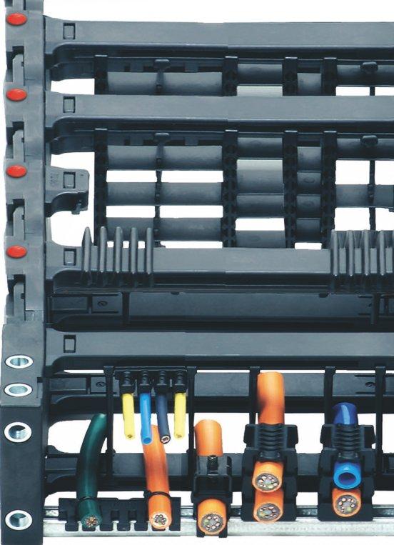
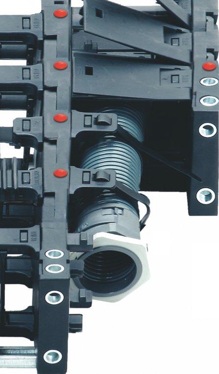
 Versatile applications For short and long travels Numerous interior separation possibilities Can be opened from two sides - reduce assembly time E-Tube for chip protection Maximum robustness")


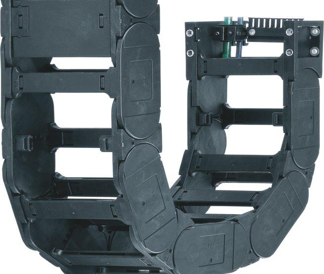
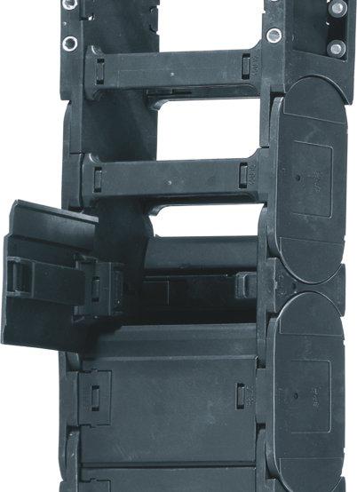
3 System E4 4-piece E-Chains Modular and robust E4/00 Standard System E4/00 Your first choice in E4 - The standard broad application spectrum Low noise - Noise reduction with TÜV certificate (Series E4/101) Versatile applications For short and long travels Numerous interior separation possibilities Can be opened from two sides - reduce assembly time E-Tube for chip protection Maximum robustness and life Wide smooth interior surface - cable and hose friendly Excellent in all environments E4/00 from page 7.6 E4/4 E4/4 - with "tongue and groove" - high stability even when side-mounted Special: side-mounted and travels over 450 m Side-mounted - unsupported Best for "ESD" versions High torsional rigidity Also available as ol E-Chain Strong in rough operation Can be opened from two sides - reduce assembly time E-Tube for chip protection Maximum robustness and life Wide smooth interior surface - cable and hose friendly Excellent in all environments E4/4 from page 7.86 E4/light E4/light - lighter sidelinks, low weight, cost-effective Special: Low weight, low cost Outer link with rear catch - high stability "side-mounted" Price saving with "light" design Optimized ratio of interior and exterior dimension Low weight Short travel with lighter loads Can be opened from two sides - reduce assembly time E-Tube for chip protection Maximum robustness and life Wide smooth interior surface - cable and hose friendly Excellent in all environments 7.2 Comprehensive information for each range E4/light from page can be found at the relevant web link
4 System E4 Selection chart Whatever E-Chain application you have, you can probably do it with the elements of the E4 modular family! Just let us know what you need, and we will build it for you within hours. Choose your E4 system: E4/00 - the most versatile of the E4 E-ChainSystems is a safe choice for most applications. By the "inner link - outer link" principle, the installation and dismantling are simple. Design features like the "brakes" in the chain stop dog clearly reduce the operation noise level. E4/4 - for extremely long travels and for unsupported, side-mounted application. The "tongue and groove" between two chain links enables this feature. Compression forces and stability are enhanced, and resistance against dirt and debris is increased. Special roller chain links make E4/4 real specialists for long travels. The tongue and groove design similarly enables outstanding ESD/ATEX performance. The chain links are tightly linked to each other, so that electricity can flow through them when in contact with each other (Please note: This is valid only for the special conductive material igumid ESD and is not applicable for the standard reduced thickness of the side link (for all types) and a thinner crossbar (for some types: 14240, 14340, and 1640). Lower weight, larger inner space and lower price. E4/light E-Chain attains solutions with an optimum price/performance ratio for many industrial applications. Especially good for short travels, hanging and small, standing designs. E4/light types are often the first choice. System E4 System E4 - Comparison of the main characteristics hi m m [mm] [mm] [mm] max. [m] max. [kg/m] max. [m/s] [C ] kg C E4/ C E4/ ,0 20 E4/light ,0 6, C 3-40 C Unsupported length FL G = with straight upper run FL B = with permitted sag Inner heights from - to [mm] Inner widths from - to [mm] Bending radii from - to [mm] Unsupported lengths [m] Fill weights [kg/m] Speed max. FL G Speed max. FL B Gliding speed max. Long term temp. min/max. [ C] Comprehensive information for each range can be found at the relevant web link 7.3
5 System E4 Broad system of modular accessories Interior separations - various possibilities Vertical separators Vertical separators, slotted Side plates Locking shelves Mounting brackets - various possibilities KMA with attachment capability on all sides Mounting bracket KMA polymer pivoting with or without C-profile Mounting bracket KMA polymer locking with or without C-profile Mounting bracket made of steel Strain relief elements from chapter 10 Integration with igus KMA mounting brackets possible Improved housing foot clamp for easy fit into C-profile Clip-on tiewrap plates for snap-open crossbars Tiewrap plates can be clipped directly into the C-profile Guide troughs - for long travels chapter 9 Basic Heavy Aluminum "Super Trough"- modular trough system - Basic version and Heavy-Duty-version with add-on items Steel guide troughs - very rugged, large selection Aluminum guide troughs - simple assembly, light weight Additional features use product link on each page for details Widths up to 3000 mm due to extension links Extender crossbars for various E4 E-Chains available Hinged crossbars - 4 options available SnapClip for E4 E-Chains for attaching an additional conduit 7.4 Comprehensive information for each range can be found at the relevant web link

6 System E4 Many accessories + = ol E-Chain - Major reduction in drive power chapter 9 System E4 + = AUTO-GLIDE for long travels without guide troughts chapter 9 + = + = E4/101 - optimal low-noise solution, with rubber pads, in the igus System E4-program chapter 7 Extender Crossbar - outer link suited for attaching an additional conduit chapter 7 + = E4 eadychain - Plug-and- Play E-ChainSystems - all inclusive page 1.41 Selecting a System E4 E-Chain Application Profile Application High tensile forces High shearing forces Unsupported length, straight Unsupported length, with sag Unsupported, side-mounted Gliding, side-mounted High speeds High accelerations atio of inner dimension to outer dimension (space required) Low fill weight required Zig-zag applications Environment olling noise generation Gliding noise generation High, constant humidity and temperature Dirt resistance Chip protection Insensitivity to vibration and shock Closed exterior and stop dogs Service life Unsupported, straight Unsupported, with sag Gliding Installation Opening/closing Separating / joining E4/00 E4/4 E4/light ++ + o o o + ++ very well-suited + well-suited o conditionally suitable not suitable E4/00 Series 220, 280, 380, 400, 600, 640, 840, 800 and modified options E4/4 Series 2828, 3838, 4040, 5050 and modified options E4/light Series 14040, 14240, 15050, 1640 and modified options Comprehensive information for each range can be found at the relevant web link 7.5
7 7.6
8 E4/00 7.7
 Broad application spectrum Numerous interior separation possibilities Broad system of modular accessories Widths up to 2000 mm using")
9 System E4/00 Excellent stability Noise absorbing buffer Can be opened from both sides Material igumid G -40/+120 C Lateral glide surfaces E4/00: E-Chains with a 4-piece design link Lowest noise in its class Further noise reduction with rubber pads (Series E4/101) Broad application spectrum Numerous interior separation possibilities Broad system of modular accessories Widths up to 2000 mm using extension links Maximum stability in the igus range Can be opened along both radii Max. travel: m You can find more technical data about the material, chemical resistance, temperatures Design, from page 1.38 Opening-principle Dimensioning Bending radius structure Can be opened from both sides Can be opened from both sides and hinged open on one side Ba hi ha Bending radius Color black adius Width Series Selection table Series Inner height Inner width Outer width Outer height Bending radius Unsupported page hi [mm] [mm] Ba [mm] ha [mm] [mm] length max. [m] Crossbars every link, for particulary demanding applications , , , , , , , , , Crossbars every other link, for almost all applications , , , , E-Tube - fully enclosed, excellent cable protection , , , , ,
10 System E4/00 Selection chart E4/00 Comparison of the main characteristics hi m m [mm] [mm] [mm] max. [m] max. [kg/m] max. [m/s] [C ] kg C E4/00 E-Chain Crossbars every link C E4/00 E-Chain Crossbars every 2 nd link ,0 7,0 7, E4/00 E-Tube Fully enclosed C 3-40 C Unsupported length FL G = with straight upper run FL B = with permitted sag Inner heights from - to [mm] Inner widths from - to [mm] Bending radii from - to [mm] Unsupported lengths [m] Fill weights [kg/m] Speed max. FL G Speed max. FL B Gliding speed max. Long term temp. min/max. [ C] Additional quality features - System E4/00 IPA Certificate, Cleanroom ISO Class 3 at v=1 m/s and ISO Class 4 at v= 2 m/s for Series tested with igus Chainflex cables ESD/ATEX upon request System E4/00 proved for long travels System E4-4-piece design link Low-noise due to special rubber pads design Next Page: Find application examples and assembly instructions 7.9
.")


11 System E4/00 Applications E4/00 (pronounced: E4-hundred) as the most versatile of the E4 chains is a safe choice in almost all applications (Note: Choose E4/4 for travels > 150 m and for "on the side-unsupported"). Its "inner link - outer link" design makes it easy to assemble and disassemble on site. The "noise buffer" design feature reduces operating noises noticeably. obustness pairs with elasticity, when external vibrations attack. As a standard chain with the broadest application spectrum, the version E4/00 can be used almost everywhere without special knowledge of the respective application. The E4/00 is available around the world from stock. Typical industries & applications obotics and handling Material handling Freezing environment Construction machinery Machine tools Woodworking machinery Machines of all kinds Semicon Cleanroom General machinery obust, quiet, modular - E4/00 sets the benchmark Quiet and strong - ideal for handling applications of all kinds obust engineering for construction equipment Long unsupported spans, high stability High accelerations, references with more than 50 Million cycles 7.10
12 System E4/00 Assembly instructions E4/00 System E4/00 E-Chains Opening 1 2 System E4/00 E-Tubes Opening 1 2 emove crossbars - Insert screwdriver into the slot, push down, release by lever action emove clips - Insert screwdriver into the slot and push down, release by lever action emove lids/bottoms - Insert screwdriver into the slot, release by lever action elease only one side to swivel the lid System E4/00 E-Chains and E-Tubes Assembling Line up two inner side links, side by side. Attach an outer side link between Assemble crossbars - Push down and snap in by using a screwdriver Assemble clips (E-Chains with crossbars every other link) - Push down and snap in Assemble E-Tube lids/bottoms - Attach to the connector at an angle - Snap in System E4/00 E-Chains and E-Tubes Separating emove crossbars, clips, lids and bottoms at the outer links......guide the screwdriver into the slot between side links and release it by levering......remove the outer links to the side......and separate the E-Chain You can find an assembly video on the web

13 210 E4/00 System E4/00 Series Clean- oom Price index Low-noise Cleanroom test upon request ESD classification: Electrically conductive ESD/ATEX version upon request Crossbars are removable along both radii Stop dog with "brake" for noise reduction Wide, rounded plastic crossbars - cable friendly Optimized glide pads Interior separation with standard locking separator Integrated strain relief possible Mounting brackets pivoting on one side with all-round attachment option Dirt-repellent exterior E-Chains also available with reverse bending radius "B" Tongue and groove for more stability Strain relief separator - Separator with integrated strain relief for the use in the first or last chain link page 7.16 Opening E-Chains : emove crossbars and clips - Insert screwdriver into the slot, push down, release by lever action. epeat action for the other side When to use the Series 210: If a low-noise version is required At very high speeds and/or accelerations For long travels When not to use it: If an extrem vibration-free E-Chain is necessary Series E3.22, page 8.18 When an E-Chain or E-Tube is required that snaps open only to one side, to realize cost savings Series 1400/1450/1480/1500, page 5.84 When E-Tubes that snap open to one side only are desired, at a lower cost Series 117/118, page 6.6 Order example complete E-Chain Please indicate chain-lenghts or number of links Example: 2 m or 66 links 2 m E-Chain with 2 separators T2112 every 2 nd link Interior separation 1 set Mounting bracket D-CAD files, pdf-downloads and many online features
14 System E4/00 Series 210 Dimensions and Technical Data 210 E4/00 Unsupported length FL G = with straight upper run FL B = with permitted sag Further information Design, page 1.12 HF H D S (FL G ) S (FL B ) FL G FL B S S/2 Moving end Fixed end ,5 FL G FL B Unsupported length FL G / FL B [m] Length of travel S [m] Pitch = 30,5 mm/link Links/m = 33 (1007mm) Chain length = S / 2 + K H D K D K H Fill weight [kg/m] 28 H - 28 H H F = H + 30 S = Length of travel = Bending radius H = Nominal clearence height H F = equired clearence height H I = Trough inner height D = Overlength E-Chain radius in final position K = π + "safety" D 2 = Over length - long travels, gliding K 2 = *Further add-on H 2 = *Mounting height *if the mounting bracket location is set lower Other installation methods Vertical, hanging 40 m Vertical, standing 3 m Side mounted, unsupp. 1 m otary requires further calculation Unsupported length of upper run = upon request Short travels - unsupported Unsupported E-Chains feature positive camber over short travels. This must be accounted for when specifying the clearance height H F. Please consult igus if space is particularly restricted. The required clearance height: H F = H + 30 mm (with 1,5 kg/m fill weight) 21 System E4/00 Inner height: 21 mm Long travel lengths from 10 m to max. 120 m Chain length = S / 2 + K 2 S S/2 S/2 Moving end Fixed end H2 D2 K2 Guide trough with glide bar Guide trough without glide bar Total length of guide trough In case of travels between 4 and 10 m we recommend a longer unsupported length. HI Gliding, long travel applications (max. 120 m) In this case the E-Chain upper run will be introduced in a guide trough on the lower run. We recommend to realize the engineering of such a plant by our technicians. Speed / acceleration FL G max. 20 [m/s] / max. 200 [m/s 2 ] Speed / acceleration FL B max. 3 [m/s] / max. 6 [m/s 2 ] Gliding speed / acceleration (maximum) max. 10 [m/s] / max. 50 [m/s 2 ] Material - permitted temperature C igumid G / -40 up to +120 C Flammability class, igumid G VDE 0304 IIC UL94 HB Technical Data C Details of material properties page 1.38 page D-CAD files, pdf-downloads and many online features
15 210 E4/00 System E4/00 Series 210 Product ange Ba = + 14 Series E-Chain with crossbars every link igus E-ChainSystems 18 max structure Color black Bending radius obust solution with crossbars every link Can be opened from two sides emovable crossbars Part.... No.... Ba Weight [mm] [mm] [kg/m] , , , , , , , ,92 igus GmbH Cologne E-Chain links, single parts Inner side link Outer side link [mm] Inner side links, each left/right or outer side links, each left/right Single crossbar, Outer side link, single part (suitable for all radii) Inner side link, single part Single crossbar, Internet: info@igus.de Width Series The widths 90 / 110 are available upon request. Time of delivery approx. 6-8 weeks after order. Available bending radii Supplement with required radius. Example: = standard color, other colors page 1.39 Pitch = 30,5 mm/link - Links/m = D-CAD files, pdf-downloads and many online features
16 System E4/00 Series 210 Accessories Interior Separation 210 E4/ min.13 2 T2112 Option 1: Vertical separators 111.X T2111 1,5 Vertical separators are used if a vertical subdivision of the E-Chain interior is required - By standard vertical separators are every other E-Chain link. Note: Observe a 8 lateral spacing of at least 13 mm! 1,5 Standard separator T2102 is used when vertical and horizontal separation is required. Due to its slot, it allows basic vertical/horizontal shelving arrangements. Notch separator T2101 can be locked in 2 mm increments due to gaps on the crossbars. The separator cannot slide sideways during operation. Strain relief separator T2103.Z can be integrated into the mounting bracket and can be placed there at any point. It combines strain relief and interior separation Vertical separator un T2102 T2112 Notch separator un T2101 T2111 Strain relief separator un T2103.Z T2113.Z Option 1 Vertical separators Full-width shelves Vertical separator T2102 Notch separator T2101 Strain relief separator T2103.Z System E4/00 Inner height: 21 mm Full-width shelf 110.X Additionally: Full-width shelf 110.X - this option makes sense in applications with many thin cables with similar diameters. It is based upon vertical separator T2102 and T2101, with inserted full-width shelves. Width X [mm] un Width X [mm] un Full-width shelf X t = 2 page D-CAD files, pdf-downloads and many online features
17 210 E4/00 System E4/00 Series 210 Accessories Mounting Brackets Moving end The attachment variants arising automatically by the choice of the KMA mounting bracket The Standard - option polymer, pivoting ecommended for unsupported and gliding applications KMA mounting bracket with attachment capability on all sides Well suited for tight installation conditions Integrated strain relief possible Variable traverse angle for flexible assembly Fixed end Dimensions and order configurations Moving end Fixed end , igus GmbH Cologne structure Full set Index Width Serie Full set, for both ends: Single-part order:bei Mounting bracket with bore Mounting bracket with pin For E-Chain 8,5 SW7 ø4,3 / t=5,2 8,5 full set [mm] For E-Chain full set [mm] Special feature mounting brackets KMA: Series 210 Mounting brackets with attachment points on all sides Special design of the counterbore as hexagon - the inlay of the nut (M4) and the counterboring of the hexagon socket head srew (M4), is consequently possible Attention: Mounting brackets always need to end with an inner plate (odd number of links) + 18 Internet: info@igus.de 10 T2103.Z Other strain relief elements chapter 10 System E4/00 Series 210 Accessories Strain elief Strain relief separator Separator with integrated strain relief, for use in the first or last chain link. For manufacturing of switchgear cabinets or for the assembly of machines. Easy to assemble without any fastening device. Separator base T2103.Z is 8 mm wide. The possible number of separators per E-Chain is defined by its inner width and by the cable-diameter. Details chapter 10 Number of teeth For Series T2103.Z 2 one side D-CAD files, pdf-downloads and many online features
18 SL SL Trough height: 77 mm Aluminum "SuperTrough" Basic Version 210 E4/ Bottom clamp attached optionally inwards or outwards M6 x16 B a B i Ba Ba ha ,7 Length of the C-profile according to dimension B i Components, trough "Basic": Trough side parts, aluminum, 2 m Glide bar, plastic, 2 m Glide strips, plastic, 2 m (without glide strips on request) Optional: Silencer profile, rubber Components, installation set "Basic": Bottom clamp, aluminum C-profile, steel galvanized Screw M6 x16 Sliding nut M6 Interface connector, plastic Order example: Length of travel 30 m - Center mounted for Series with B i = 68 Guide trough set (set of 2 trough side parts, incl. glide strips) without glide bar Order text: 16 m Guide trough without glide bar (8 x 2 m sections) Guide trough set (set of 2 trough side parts, incl. glide strips) with glide bar Order text: 16 m Guide trough with glide bar (8 x 2 m sections) Installation set "Basic" complete (Guide trough-sets + 1) Order text: 17 Installation sets "Basic" see table H i 2 x ha H a = SL SL Ba ha =Outer width E-Chains / E-Tube =Inner width E-Chains / E-Tube =Outer height E-Chains / E-Tube H i =Inner trough height H a =Outer trough height B i =Inner trough width depends on dim. Ba B a =Outer trough width n Mon =Number of installation sets (left/right) n i =Number of trough sets (left/right)! H i 2 ha B i Ba + 4 = Guide trough set = Glide bar = Installation set "Basic" = C-profile Installation set "Basic" with C-profile Bottom Clamp attached optionally inwards or outwards Order example B i attached attached [mm] inwards outwards n Mon = n i + 1 n i x 2000 mm Principle sketch: Number of installation sets to be installed = Number of trough sections + 1 Other guide trough systems chapter 10 chapter 9 "Steel trough" very stable and robust guide trough out of steel, 2 pieces, adjustable on chain width page 7.11 Details about Alu "SuperTrough" and further guidance possibilities chapter 9, Guide Troughs 7.17
19 E4/00 System E4/00 Series Price index Series 220 Clean- oom Series 760 Low noise version E4/101 Series 221 available with special rubber pads design Cleanroom test upon request ESD classification: Electrically conductive ESD/ATEX version upon request Crossbars are removable along both radii Wide, rounded plastic crossbars - cable friendly Stop dog with "brake" for noise reduction Closed and open styles can be combined Hinged snap-open removable lids along outer radius of E-Tube Optimized glide pads Numerous interior separation possibilities KMA mounting brackets with attachment points on all sides Locking or pivoting mounting brackets available Integrated strain relief possible E-Chains also available with reverse bending radius "B" Also available as E4/00-NC without camber: 220-NC Opening E-Chains : emove crossbars and clips - Insert screwdriver into the slot, push down, release by lever action emove lids/bottoms (E-Tubes) - Insert screwdriver into the slot, release by lever action When to use the Series 220/760: If a low-noise version is required At very high speeds and/or accelerations For long travels For high additional loads When not to use it: Zig-zag lift applications System E4/4, from page 7.86 For side-mounted applications System E4/4, from page 7.86 If an extrem vibration-free E-Chain is necessary Series E6.29/6.29, page 8.40/8.46 Order example complete E-Chain Please indicate chain-lenghts or number of links Example: 3 m or 66 links 3 m E-Chain with 2 separators 2211 every 2 nd link Interior separation 1 set Mounting bracket D-CAD files, pdf-downloads and many online features
20 System E4/00 Series Dimensions and Technical Data E4/00 Unsupported length FL G = with straight upper run FL B = with permitted sag Further information Design, page 1.12 HF H D S (FL G ) S (FL B ) FL G FL B S S/2 Fixed end Moving end 46 FL G FL B Unsupported length FL G / FL B [m] Length of travel S [m] Pitch = 46 mm/link Links/m = 22 (1012 mm) Chain length = S / 2 + K H D K D K H Fill weight [kg/m] 42 H - 42 H H F = H + 40 S = Length of travel = Bending radius H = Nominal clearence height H F = equired clearence height H I = Trough inner height D = Overlength E-Chain radius in final position K = π + "safety" D 2 = Over length - long travels, gliding K 2 = *Further add-on H 2 = *Mounting height *if the mounting bracket location is set lower Other installation methods Vertical, hanging 80 m Vertical, standing 5 m Side mounted, unsupp. 2 m otary requires further calculation Unsupported length of upper run = upon request Short travels - unsupported Unsupported E-Chains feature positive camber over short travels. This must be accounted for when specifying the clearance height H F. Please consult igus if space is particularly restricted. The required clearance height: H F = H + 40 mm (with 1,0 kg/m fill weight) 28 System E4/00 Inner height: 28 mm Long travel lengths from 10 m to max. 200 m Chain length = S / 2 + K 2 S S/2 S/2 Moving end Fixed end H2 D2 K2 Guide trough with glide bar Guide trough without glide bar Total length of guide trough In case of travels between 4 and 10 m we recommend a longer unsupported length. HI Gliding, long travel applications (max. 200 m) In this case the E-Chain upper run will be introduced in a guide trough on the lower run. We recommend to realize the engineering of such a plant by our technicians. Speed / acceleration FL G max. 20 [m/s] / max. 200 [m/s 2 ] Speed / acceleration FL B max. 3 [m/s] / max. 6 [m/s 2 ] Gliding speed / acceleration (maximum) max. 10 [m/s] / max. 50 [m/s 2 ] Material - permitted temperature C igumid G / -40 up to +120 C Flammability class, igumid G VDE 0304 IIC UL94 HB Technical Data C Details of material properties page 1.38 page D-CAD files, pdf-downloads and many online features

21 E4/00 System E4/00 Series Product ange Ba Series E-Chain with crossbars every link igus E-ChainSystems 25 max. structure Color black Bending radius obust solution with crossbars every link Can be opened from two sides emovable crossbars 25 max. Ba igus GmbH Cologne Width Series structure Color black Bending radius Width Series Series Fully enclosed E-Tube Fully enclosed Excellent cable protection against dirt Protection against hot chips (up to 900 C) Lids along the entire inner radius are completely removable. Lids along the entire outer radius are single sided snap-open with a hinge on the other side to keep them attached to the chain or completely removable. Internet: info@igus.de Unsupported application (with harnessed) E-Chain Series E4/ D-CAD files, pdf-downloads and many online features
22 System E4/00 Series Product ange Part.... No Ba [mm] [mm] [kg/m] [kg/m] ,06 220/ ,10 2, , ,18 220/ ,21 2, ,27 220/ ,32 2,54 220/ ,43 2,78 220/ ,54 3,02 220/ ,65 3,26 220/ ,76 3,50 220/ ,87 3,74 220/ ,98 3, ,09 220/ ,20 4,46 Available bending radii [mm] 055* Supplement with required radius. Example: = standard color, other colors page 1.39 Pitch = 46 mm/link - Links/m = 22 *not available for 760 TIP! Hot Chips up to 850 C E-Tubes that repel hot chips, up to 850 ºC Some applications, depending on amount and size of the chips, can burn or melt the surface. That is no longer the case with the new igus "igumid HT" material. Further information: or phone: E4/00 System E4/00 Inner height: 28 mm Inner side links, each left/right or outer side links, each left/right Single crossbar, E-Chain, 225. Single lid, E-Tube, 765. Outer side link, single part (suitable for all radii) Inner side link, single part Single bottom, E-Tube, 766. E-Chain links, single parts Inner side link Outer side link Low-noise! Special low-noise version with rubber pads Series Order example Further information: or phone TIP! page D-CAD files, pdf-downloads
23 E4/00 System E4/00 Series Accessories Interior Separation igus E-ChainSystems Option 1 Vertical separators Spacers Side plate Full-width shelves 5 5 E-Chain X E-Tube min.20 Vertical separator 2201 Vertical separator 7603 Spacer Side plate 2203 Vertical separator un Vertical separator for E-Tubes un Spacer* un Side plate un *For side-mounted applications ,5 7 Option 1: Vertical separators and spacers Vertical separators are used if a vertical subdivision of the E-Chain interior is required - By standard vertical separators are every other E-Chain link. Note: Observe a lateral spacing of at least 20 mm for E-Tubes! Standard separator 2201 is used when vertical and horizontal separation is required. Due to its slot, it allows basic vertical/horizontal shelving arrangements. Vertical separator 7603 for E-Tubes 760. Vertical separators in side-mounted applications, for instance, can be fixed in position by means of spacer A wide range of intervals between the vertical separators is adjustable here. Note on spacers: The available interior height is reduced by 2 mm per spacer (4 mm when spacers are fitted on both sides). To avoid this, the parts can also be installed from the outside on the opening crossbar. igus GmbH Cologne Full-width shelf 220.X Additionally: Side plate 2203 and full-width shelf 220.X - this option makes sense in applications with many thin cables with similar diameters. It is based upon vertical separator 2201 (7603) for the Series 760 E-Tube) is put in place and the shelf is inserted into the separator s slots. If no separators are desired, side plate 2203 must be used with the Series 220 E-Chain. This solution is not available for E-Tubes. Internet: info@igus.de Full-width shelf X-1 t = 2,5 Width X [mm] un Width X [mm] un D-CAD files, pdf-downloads and many online features

24 System E4/00 Series Accessories Interior Separation E4/00 E-Chain 5 E-Tube 5 5 Option 2 Option 2: Shelves X For applications involving many cables with different diameters. The shelves can be arranged elevator-shifted with different bottoms. Side plates 2204, middle plates 2202 and shelves 2200.X form the basic pattern of a shelf system. Shelves of various widths can be arranged at 3 different heights (in 5 mm increments). A middle plate 7602 is available for the E-Tube. Side plates are not available for the E-Tube min.20 Side plate un Middle plate un Middle plate for E-Tubes un Side plates Middle plates Side plate 2204 Middle plate 2202 Middle plate 7602 System E4/00 Inner height: 28 mm Width X [mm] un Width X [mm] un Shelf 2200.X Shelf X X-7 t = 2,5 3D-CAD files, pdf-downloads and many online features Machine tool gantry with various E4/00 E-Chains - fast movements and high cycle counts page
25 E4/00 E4/00 Series Accessories Mounting Brackets, KMA The attachment variants arising automatically by the choice of the KMA mounting bracket The Standard - Option KMA* - pivoting ecommended for unsupported and gliding applications Universal mountable with attachment capability on all sides Bolted connection outside of chain cross-section Confined installation conditions Corrosion resistant *KMA = Polymer Metal Mounting Bracket Moving end 2200/ Fixed end 2200/ The attachment variants arising automatically by the choice of the KMA mounting bracket Option KMA - locking ecommended for vertical hanging / standing applications Additionally: Universal mountable Corrosion resistant Locked connections At very high acceleration Moving end 2300/ Fixed end 2300/ Dimensions and order configurations structure (pivoting) Fixed end Moving end 2200/ (pivoting) (pivoting) 2200/ / (locking) (locking) 2300/ ,5 58,5 Full set igus GmbH Cologne Internet: info@igus.de 2200 = E-Chain 7600 = E-Tube structure (locking) odd/even Width Full set odd/even Width 2300 = E-Chain 7650 = E-Tube Note: The E4/00 System may end with either an inner side or an outer side link. Keep in mind that an outer side link always forms the first chain link at the moving end. The depends on an even or odd numbers of links. Please insert: 1 for odd number of links or 2 for even number of links Full set, for both ends: (even) Single-part order:bei (even) Mounting bracket with bore (even) Mounting bracket with pin ,5 ø5,5 t=7,2 15 Width full set index pivoting locking [mm] / / / / / / / / , Width full set index pivoting locking Please insert 1 for odd number of links or 2 for even number of links 17 [mm] / / / / / / / / / / / / System E4/00 Series Accessories Strain elief Strain relief tiewrap plate 2050.Z can be fixed on the last crossbar. Details chapter 10 Part. No. Width [mm] Number of teeth 2050.Z D-CAD files, pdf-downloads and many online features
26 SL SL Trough height: 117 mm Aluminum "SuperTrough" Basic Version Bottom clamp attached optionally inwards or outwards M6 x16 B a B i Ba + 4 Ba ha ,9 Length of the C-profile according to dimension B i 27 see table H i 2 x ha H a = 117 Components, trough "Basic": Trough side parts, aluminum, 2 m Glide bar, plastic, 2 m Glide strips, plastic, 2 m (without glide strips on request) Optional: Silencer profile, rubber Components, installation set "Basic": Bottom clamp, aluminum C-profile, steel galvanized Screw M6 x16 Sliding nut M6 Interface connector, plastic Order example: Length of travel 30 m - Center mounted for Series with B i = 94 Guide trough set (set of 2 trough side parts, incl. glide strips) without glide bar Order text: 16 m guide trough without glide bar (8 x 2 m sections) Guide trough set (set of 2 trough side parts, incl. glide strips) with glide bar Order text: 16 m guide trough with glide bar (8 x 2 m sections) Installation set "Basic" complete (guide trough-sets + 1) Order text: 17 installation sets "Basic" Module for the fixed end Order text: 1 set Option: For an additional noise dampening with SL SL silencer profile, please add Index A - Example: SLA Insert for the installation set E4/00 Ba =Outer width E-Chains / E-Tube =Inner width E-Chains / E-Tube ha =Outer height E-Chains / E-Tube H i =Inner trough height H a =Outer trough height B i =Inner trough width depends on dim. Ba B a =Outer trough width n Mon =Number of installation sets (left/right) n i =Number of trough sets (left/right)! H i 2 ha B i Ba + 4 = Guide trough set = Glide bar = Installation set "Basic" = C-profile Installation set "Basic" with C-profile Bottom Clamp attached optionally inwards or outwards Order example B i attached attached [mm] inwards outwards "Heavy-Duty": XXX instead of ( XXX) on the right column "attached outwards" n Mon = n i + 1 n i x 2000 mm Principle sketch: Number of installation sets to be installed = Number of trough sections + 1 NEW! A quick fix for mounting the stationary end of an E-Chain With this new module for the fixed end, fast and easy mounting onto the Aluminum "SuperTrough" is now possible without any drilling. Fast mounting of the E-Chain by clamping onto the aluminum trough Quick relocation of the stationary end No drilling necessary chapter 10 chapter 9 page 7.11 Details about Alu "SuperTrough" and further guidance possibilities chapter 9, Guide Troughs 7.25

27 E4/00 Price index Series 280 Series 290 Series 770 Low noise version E4/101 Series 281 available with special rubber pads design IPA Certificate, Cleanroom ISO Class 3 at v=1 m/s and ISO Class 4 at v= 2 m/s for Series ESD classification: Electrically conductive ESD/ATEX version upon request System E4/00 Series Crossbars on E-Chain removable along both radii Numerous interior separation possibilities Closed and open styles can be combined Stop dog with "brake" for noise reduction Optimized glide pads Wide, rounded plastic crossbars - cable friendly Hinged snap-open removable lids along outer radius of E-Tube KMA mounting brackets with attachment points on all sides Locking or pivoting mounting brackets available Integrated strain relief with C-profile option E-Chains also available with reverse bending radius "B" Opening E-Chains : emove crossbars and clips - Insert screwdriver into the slot, push down, release by lever action Also available as E4/00-NC without camber: 280-NC emove lids/bottoms (E-Tubes) - Insert screwdriver into the slot, release by lever action When to use the Series 280/290/770: If a low-noise version is required At very high speeds and/or accelerations For long travels For high additional loads Also available without camber When not to use it: If long side-mounted, unsupported length is required Series 2828/2928/7728, page 7.82 If an extrem vibration-free E-Chain is necessary Series E6.35, page 8.50 Order example complete E-Chain Please indicate chain-lenghts or number of links Example: 4 m or 72 links 4 m E-Chain with 2 separators 282 every 2 nd link Interior separation 1 set C Mounting bracket D-CAD files, pdf-downloads
28 System E4/00 Series Dimensions and Technical Data Unsupported length FL G = with straight upper run FL B = with permitted sag Further information Design, page 1.12 HF H D S (FL G ) S (FL B ) FL G FL B S S/2 Fixed end FL B FL G 1.0 Moving end Unsupported length FL G / FL B [m] H D K D K H Fill weight [kg/m] Length of travel S [m] Pitch = 56 mm/link Links/m = 18 (1008 mm) Chain length = S / 2 + K 54 H - 54 H H F = H + 40 S = Length of travel = Bending radius H = Nominal clearence height H F = equired clearence height H I = Trough inner height D = Overlength E-Chain radius in final position K = π + "safety" D 2 = Over length - long travels, gliding K 2 = *Further add-on H 2 = *Mounting height *if the mounting bracket location is set lower Other installation methods Vertical, hanging 80 m Vertical, standing 5 m Side mounted, unsupp. 1,5 m otary requires further calculation Unsupported length of upper run = upon request Short travels - unsupported Unsupported E-Chains feature positive camber over short travels. This must be accounted for when specifying the clearance height H F. Please consult igus if space is particularly restricted. The required clearance height: H F = H + 40 mm (with 2,0 kg/m fill weight) E4/00 32 System E4/00 Inner height: 32 mm Long travel lengths from 10 m to max. 200 m Chain length = S / 2 + K 2 S S/2 S/2 Moving end Fixed end H2 D2 K2 Guide trough with glide bar Guide trough without glide bar Total length of guide trough In case of travels between 4 and 10 m we recommend a longer unsupported length. HI Gliding, long travel applications (max. 200 m) In this case the E-Chain upper run will be introduced in a guide trough on the lower run. We recommend to realize the engineering of such a plant by our technicians. Speed / acceleration FL G max. 20 [m/s] / max. 200 [m/s 2 ] Speed / acceleration FL B max. 3 [m/s] / max. 6 [m/s 2 ] Gliding speed / acceleration (maximum) max. 10 [m/s] / max. 50 [m/s 2 ] Material - permitted temperature C igumid G / -40 up to +120 C Flammability class, igumid G VDE 0304 IIC UL94 HB Technical Data C Details of material properties page 1.38 page D-CAD files, pdf-downloads
29 E4/00 Ba System E4/00 Series Product ange Series E-Chain with crossbars every link igus E-ChainSystems 28 max. structure Color black Bending radius Crossbars every link For rigid hydraulic hoses For applications particularly demanding Can be opened from two sides Width Series 28 max. Ba structure Color black Bending radius Width Series Series E-Chain with crossbars every 2 nd link Crossbars every 2 nd link = Standard For nearly every situation Can be opened from two sides Easy assembly Stable Attractive price Ba Series Fully enclosed E-Tube Fully enclosed igus GmbH Cologne 28 max. structure Color black Bending radius Excellent cable protection against dirt Protection against hot chips (up to 900 C) Lids along the entire inner radius are completely removable. Lids along the entire outer radius are single sided snap-open with a hinge on the other side to keep them attached to the chain or completely removable. Width Series Internet: info@igus.de Low-noise! Special low-noise version with rubber pads Series Order example Further information: or phone D-CAD files, pdf-downloads
30 System E4/00 Series Product ange Part.... No Ba [mm] [mm] [kg/m] [kg/m] [kg/m] 280/290/ * ,73 1,64 2,63 280/ ,79 1,67 280/290/ ,84 1,69 2,75 280/ ,93 1,73 280/290/ ,02 1,78 2,83 280/290/ ,08 1,81 2,94 280/ ,15 1,84 280/290/ ,20 1,87 3,03 280/ ,29 1,91 280/290/ ,38 1,96 3,19 280/ ,44 1,99 280/290/ ,51 2,02 3,39 280/ ,56 2,05 280/ ,65 2,09 280/290/ ,74 2,14 3,59 280/ ,87 2,20 280/ ,92 2,22 280/ ,05 2,29 280/290/ ,10 2,32 4,04 280/ ,19 2,36 280/ ,28 2,41 280/ ,37 2,45 280/290/ ,46 2,50 4,43 280/ ,59 2,56 280/ ,68 2,60 280/ ,77 2,65 280/ ,86 2,69 280/ ,95 2,74 280/ ,04 2,79 280/ ,11 2,82 280/ ,18 2,86 Available bending radii [mm] 063** 075** 100** Supplement with required radius. Example: = standard color, other colors page 1.39 Pitch = 56 mm/link - Links/m = 18 *emovable lid only, no hinged option **not available for 770 TIP! Hot Chips up to 850 C E-Tubes that repel hot chips, up to 850 ºC Some applications, depending on amount and size of the chips, can burn or melt the surface. That is no longer the case with the new igus "igumid HT" material. Further information: or phone: Increased inner height (program extension) The Series E- Chain, with an increased inner height of 40 mm is available for unsupported applications. Please consult igus for delivery time and availability. We recommend the use of steel mounting brackets for this series. Extender crossbar for large diameter hoses page E4/00 System E4/00 Inner height: 32 mm Inner side links, each left/right or outer side links, each left/right Single crossbar, E-Chain, 385. Single lid, E-Tube, 775. Outer side link, single part (suitable for all radii) Inner side link, single part E-Chain links, single parts Inner side link Outer side link Single bottom, E-Tube, 776. page D-CAD files, pdf-downloads
31 E4/00 E4/00 Series Accessories Interior Separation igus E-ChainSystems Option 1 Vertical separators Spacers Locking separators Asymmetric separators E-Chain E-Tube 282A X T min.20 igus GmbH Cologne Internet: info@igus.de Vertical separator 281 Vertical separator 281T Vertical separator Vertical separator 283 Spacer Spacer Spacer Locking separator 293 Asymmetric separator 281A Vertical separator un Vertical separator for E-Tubes un T 282T Vertical separator /E-Tubes un Vertical separator un Spacer* un Spacer* un Spacer* un Locking separator un Asymmetric separator un *For side-mounted applications A 282A 2,5 12 2, ,5 14 2, ,5 10 2,5 2,75 12 Option 1: Vertical separators and spacers Vertical separators are used if a vertical subdivision of the E-Chain interior is required - By standard vertical separators are every other E-Chain link. Observe a lateral spacing of at least 20 mm for E-Tubes! Standard separator 281 offers safe stability due to its wide base design, also when used with thick cables or hoses. If the distance needed between separators is greater than this separator s dimension, we offer the vertical separator The vertical separator 281T for E-Tubes clamps to the fixed radius and remains free along the other radius to facilitate lid removal. If installing these yourself, please ensure that they are identically aligned. If the distance needed between separators is greater than this separator s dimension, we offer the vertical separator Vertical separator 283 with a narrow base with applications where a large number of small cables need to be individually separated. Vertical separators in side-mounted applications, for instance, can be fixed in position by means of spacer 381.X. A wide range of intervals between the vertical separators is adjustable here. Note on spacers: The available interior height is reduced by 2 mm per spacer (4 mm when spacers are fitted on both sides). To avoid this, the parts can also be installed from the outside on the opening crossbar. Additionally: Locking separator with increased retention force for applications exposed to very high humidity or extreme loads. The extra retention force is achieved by asymmetric claws for the crossbar. Ensure proper alignment. Asymmetric separator 281A (not for E- Tubes) with an 12-mm base, for combinations between spacers of different widths and vertical separators in side-mounted applications, for instance D-CAD files, pdf-downloads
32 E4/00 Series Accessories Interior Separation E4/00 7 Option 2: Shelves X Side plate For applications involving many cables with different diameters. /E-Tubes The shelves can be arranged elevator-shifted with un 286 different bottoms Side plates 286, middle plates 288 und shelves 386.X Middle plate form the basic pattern of a shelf system. Shelves of various /E-Tubes widths can be arranged at 3 different heights (in 7 mm un 288 increments) For special applications: Vertical separator with injection 2,5 57,5 Vertical separator moulded shelf 281.S.57 (57,5 mm) or 281.S.45 (45 mm). /E-Tubes un 281.S.57 Slotted separators 291 (not for E-Tubes), are used for S.57 very fine subdivisions. However, they cannot be retrofitted into an existing separation system without dismantling the interior 2,5 45 Vertical separator separators first. /E-Tubes un 281.S.45 The unilateral open, slotted separator 297 can be S.45 retrofitted into an existing interior separation system without a need for dismantling the interior separators. During an 3 Slotted separator installation of open slotted separators, the top and bottom notches cannot be occupied by shelves. un Option 2 Side plates Middle plates Vertical separators Slotted separators Open slotted separators Side plate 286 Middle plate 288 Vertical separator 281.S.57 Vertical separator 281.S.45 Slotted separator 291 System E4/00 Inner height: 32 mm 2,5 8 Open slotted separator /E-Tubes un Open slotted separator 297 Width X [mm] un Width X [mm] un Shelf 386.X Shelf X-8 4 page D-CAD files, pdf-downloads
33 E4/00 igus E-ChainSystems System E4/00 Series Product ange Extension links - for extremely wide E-Chains up to 3,0 m For applications in which particularly high fill weights necessitate extremely wide E-Chains (up to 3000 mm) The extension link design allows virtually limitless side-by-side attachment of chains The unsupported length of a chain can be increased when additional loads are required Extension links can be used with E-Chains, E-Tubes or as a combination of both They are suitable for unsupported and gliding applications in a guide trough E-Chains with extension links are attached with KMA or steel mounting brackets structure /20 / /2/ ,5 12, ± 3 ( ) + 13 ± 3 Extender crossbars - careful guide of hosed applications Suitable for hoses with a maximum outer diameter of 115 mm Gliding operation with crossbars along the outer radius and a special guide trough Gliding operation not guaranteed with crossbars along the inner radius The extender crossbar can either be attached to the side links directly or can be used in combination with two stranded snap-open crossbars ø 5,5 igus GmbH Cologne Consult igus for your extender crossbar applications. We are happy to assist you with your design layout HD115 round extender crossbar D115 round strap combined with snap-open crossbars attached directly on the side link Max Ø [mm] Form Installation Combination with hose side link snap-open crossb HD D = round + = yes / = no Internet: info@igus.de ,5 mm Hinged crossbars Typically E-Chain crossbars are completely removable. In cases where the snap-open crossbars have to remain at the open link of the E-Chain, a hinged design has been developed Length: 37,5 mm / snap-open crossbar (shortened): -37,5 mm Please consult igus for design assistance Option 1 Option 2 Option 3 Option 4 Ba Ba Ba Ba D-CAD files, pdf-downloads
34 E4/00 Series Accessories Mounting Brackets, KMA E4/00 Moving end The Standard - Option KMA* - pivoting ecommended for unsupported and gliding applications Confined installation conditions Option - integrated C-profile strain relief device with Chainfix clip or strain relief tiewrap plates Corrosion resistant Universal mountable with attachment capability on all sides *KMA = Polymer Metal Mounting Bracket 2800/ Fixed end 2800/ The attachment variants arising automatically by the choice of the KMA mounting bracket Standard position C-profile Moving end Option KMA - locking ecommended for vertical hanging / standing applications Additionally: Universal mountable C-profile option Corrosion resistant Locked connections At very high acceleration 2900/ Fixed end 2900/ The attachment variants arising automatically by the choice of the KMA mounting bracket Standard position C-profile Fixed end Moving end 2800/ (pivoting) (pivoting) 2800/ / (locking) (locking) 2900/ ,5 22,5 Width full set C-profile index pivoting locking option [mm] / / C C / / C C / / C / / C C / / C C / / C C / / C C C / / C , C 212 Please insert 1 for odd number of links or 2 for even number of links ø5,5 / t=7,2 12, Width full set C-profile index pivoting locking option [mm] C C / / C C C C / / C C C C C C C C C 400 Dimensions and order configurations structure (pivoting) C Optional with C-profile Full set odd/even Width 2800 = E-Chain 7700 = E-Tube structure (locking) C Optional with C-profile Full set odd/even Width 2900 = E-Chain 7750 = E-Tube Note: The E4/00 System may end with either an inner side or an outer side link. Keep in mind that an outer side link always forms the first chain link at the moving end. The depends on an even or odd numbers of links. Please insert: 1 for odd number of links or 2 for even number of links Full set, for both ends: C (even) Single-part order:bei C (even) Mounting bracket with bore C (even) Mounting bracket with pin page D-CAD files, pdf-downloads
35 E4/00 igus E-ChainSystems igus Chainfix steel clamps and Chainfix stainless-steel clamps - max. pull forces, adjustable with hexagon socket. Available as single, double or triple clamps. Details chapter 10 E4/00 Series Accessories Strain elief Chainfix clamps for the C-profile single clamps double clamps triple clamps Cable steel stainless steel steel stainless steel steel stainless steel ø [mm] CFX12.1 CFX12.1.E CFX12.2 CFX12.2.E CFX CFX14.1 CFX14.1.E CFX14.2 CFX14.2.E CFX CFX16.1 CFX16.1.E CFX16.2 CFX16.2.E CFX CFX18.1 CFX18.1.E CFX18.2 CFX18.2.E CFX CFX20.1 CFX20.1.E CFX20.2 CFX20.2.E CFX CFX22.1 CFX22.1.E CFX22.2 CFX22.2.E CFX CFX26.1 CFX26.1.E CFX26.2 CFX26.2.E CFX30.1 CFX30.1.E CFX30.2 CFX30.2.E CFX34.1 CFX34.1.E CFX34.2 CFX34.2.E CFX38.1 CFX38.1.E CFX42.1 CFX42.1.E Chainfix Clip - Modular snap-on strain relief device for C-profile Available for all igus E-ChainSystems with C- profiles and also suitable for assembly in the KMA mounting brackets and clip-on strain relief for crossbars. High pull forces, plug-in modular snapon strain relief device. Details chapter 10 Chainfix Nugget for the C-Profil Strain relief for the fixation of cables up to a diameter of Ø 20 mm. Easy to assemble, without any screws and tools. Easy strain relief due to fixation with preharnessed cable strap, very small space requirement. Details chapter 10 Cable ø [mm] clamp bottom part CFC-08-M CFC-08-C CFC-12-M CFC-12-C CFC-16-M CFC-16-C CFC-20-M CFC-20-C CFC-24-M CFC-24-C ø max. Width conduit [mm] [mm] CFN ,8 igus GmbH Cologne Chainfix tiewrap plates with clip-on connection for the C-profile Can be plugged into the KMA C-profile. Easy to assemble without any screws. Easily solvable with screwdriver nevertheless safe stop. For all E-Chains with KMA and integrated C-profile. Details chapter 10 Width of Number strain relief [mm] of teeth 3050.ZC ZC 75 7 Internet: info@igus.de Single tiewrap plate Shown Tiewrap plate as individual part As individual component screwed on KMA. Can be plugged in the mounting brackets. Details chapter 10 C B / (n-1) x 10 Tiewrap No. of Dim. C Dim. B Center plate teeth n [mm] [mm] bore 3050.ZB ZB ZB ZB ZB ZB ZB ZB ZB ZB ( = no / + = yes) 7.34 Details about all strain relief option for this series chapter 10
36 SL SL Trough height: 117 mm Aluminum "SuperTrough" Basic Version Bottom clamp attached optionally inwards or outwards n Mon = n i + 1 M6 x16 B a B i Ba + 4 Ba ha ,9 Length of the C-profile according to dimension B i n i x 2000 mm 27 see table H i 2 x ha H a = 117 Components, trough "Basic": Trough side parts, aluminum, 2 m Glide bar, plastic, 2 m Glide strips, plastic, 2 m (without glide strips on request) Optional: Silencer profile, rubber Components, installation set "Basic": Bottom clamp, aluminum C-profile, steel galvanized Screw M6 x16 Sliding nut M6 Interface connector, plastic Order example: Length of travel 30 m - Center mounted for Series with B i = 327 Guide trough set (set of 2 trough side parts, incl. glide strips) without glide bar Order text: 16 m guide trough without glide bar (8 x 2 m sections) Guide trough set (set of 2 trough side parts, incl. glide strips) with glide bar Order text: 16 m guide trough with glide bar (8 x 2 m sections) Installation set "Basic" complete (guide trough-sets + 1) Order text: 17 installation sets "Basic" Module for the fixed end Order text: 1 set Option: For an additional noise dampening with silencer profile, please add Index A - Example: SL SL SLA Principle sketch: Number of installation sets to be installed = Number of trough sections + 1 NEW! A quick fix for mounting the stationary end of an E-Chain With this new module for the fixed end, fast and easy mounting onto the Aluminum "SuperTrough" is now possible without any drilling. Fast mounting of the E-Chain by clamping onto the aluminum trough Quick relocation of the stationary end No drilling necessary page 9.16 Details about Alu "SuperTrough" and further guidance possibilities Ba ha =Outer width E-Chains / E-Tube =Inner width E-Chains / E-Tube =Outer height E-Chains / E-Tube Insert for the installation set "Heavy-Duty": XXX instead of ( XXX) on the right column "attached outwards" E4/00 H i =Inner trough height H a =Outer trough height B i =Inner trough width depends on dim. Ba B a =Outer trough width n Mon =Number of installation sets (left/right) n i =Number of trough sets (left/right)! H i 2 ha B i Ba + 4 = Guide trough set = Glide bar = Installation set "Basic" = C-profile Installation set "Basic" with C-profile Bottom Clamp attached optionally inwards or outwards Order example B i attached attached [mm] inwards outwards chapter 9, Guide Troughs chapter 10 chapter 9 page
37 E4/00 Price index Series 380 Series 390 Series 780 Clean- oom Low noise version E4/101 Series 381 available with special rubber pads design Cleanroom test upon request ESD classification: Electrically conductive ESD/ATEX version upon request System E4/00 Series Crossbars on E-Chain removable along both radii Stop dog with "brake" for noise reduction Closed and open styles can be combined Hinged snap-open removable lids along outer radius of E-Tube Numerous interior separation possibilities Optimized glide pads with lateral wear allowance Wide, rounded plastic crossbars - cable friendly Integrated strain relief possible KMA mounting brackets with attachment points on all sides Locking or pivoting mounting brackets available E-Chains also available with reverse bending radius "B" Opening E-Chains : emove crossbars and clips - Insert screwdriver into the slot, push down, release by lever action Also available as E4/00-NC without camber: 380-NC emove lids/bottoms (E-Tubes) - Insert screwdriver into the slot, release by lever action When to use the Series 380/390/780: If a low-noise version is required At very high speed and/or acceleration For long travels For high additional loads Also available without camber When not to use it: If long side-mounted, unsupported length is required Series 3838/3938/7838, page For increased inner height of 52 mm Series 38022, page If an extrem vibration-free E-Chain is necessary Series E6.40/6.40, page 8.56 Order example complete E-Chain Please indicate chain-lenghts or number of links Example: 5 m or 75 links 5 m E-Chain with 2 separators 382 every 2 nd link Interior separation 1 set C Mounting bracket D-CAD files, pdf-downloads
38 System E4/00 Series Dimensions and Technical Data Unsupported length FL G = with straight upper run FL B = with permitted sag Further information Design, page 1.12 HF H D S (FL G ) S (FL B ) FL G FL B S S/2 Fixed end Moving end 67 FL G FL B Unsupported length FL G / FL B [m] Length of travel S [m] Pitch = 67 mm/link Links/m = 15 (1005 mm) Chain length = S / 2 + K H D K D K H Fill weight [kg/m] 64 H - 64 H H F = H + 40 S = Length of travel = Bending radius H = Nominal clearence height H F = equired clearence height H I = Trough inner height D = Overlength E-Chain radius in final position K = π + "safety" D 2 = Over length - long travels, gliding K 2 = *Further add-on H 2 = *Mounting height *if the mounting bracket location is set lower Other installation methods Vertical, hanging 100 m Vertical, standing 6 m Side mounted, unsupp. 2 m otary requires further calculation Unsupported length of upper run = upon request Short travels - unsupported Unsupported E-Chains feature positive camber over short travels. This must be accounted for when specifying the clearance height H F. Please consult igus if space is particularly restricted. The required clearance height: H F = H + 40 mm (with 2,0 kg/m fill weight) E4/00 42 System E4/00 Inner height: 42 mm Long travel lengths from 10 m to max. 300 m Chain length = S / 2 + K 2 S S/2 S/2 Moving end Fixed end H2 D2 K2 Guide trough with glide bar Guide trough without glide bar Total length of guide trough In case of travels between 4 and 10 m we recommend a longer unsupported length. HI Gliding, long travel applications (max. 300 m) In this case the E-Chain upper run will be introduced in a guide trough on the lower run. We recommend to realize the engineering of such a plant by our technicians. Speed / acceleration FL G max. 20 [m/s] / max. 200 [m/s 2 ] Speed / acceleration FL B max. 3 [m/s] / max. 6 [m/s 2 ] Gliding speed / acceleration (maximum) max. 10 [m/s] / max. 50 [m/s 2 ] Material - permitted temperature C igumid G / -40 up to +120 C Flammability class, igumid G VDE 0304 IIC UL94 HB Technical Data C Details of material properties page 1.38 page D-CAD files, pdf-downloads
39 E4/00 Ba System E4/00 Series Product ange Series E-Chain with crossbars every link igus E-ChainSystems 38 max. structure Color black Bending radius Crossbars every link For rigid hydraulic hoses For applications particularly demanding Can be opened from two sides Width Series 38 max. Ba structure Color black Bending radius Width Series Series E-Chain with crossbars every 2 nd link Crossbars every 2 nd link = Standard For nearly every situation Can be opened from two sides Easy assembly Stable Attractive price Ba Series Fully enclosed E-Tube Fully enclosed igus GmbH Cologne 38 max. structure Color black Bending radius Excellent cable protection against dirt Protection against hot chips (up to 900 C) Lids along the entire inner radius are completely removable. Lids along the entire outer radius are single sided snap-open with a hinge on the other side to keep them attached to the chain or completely removable. Width Series Internet: info@igus.de Low-noise! Special low-noise version with rubber pads Series Order example: Further information: or phone D-CAD files, pdf-downloads
40 System E4/00 Series Product ange Part.... No Ba [mm] [mm] [kg/m] [kg/m] [kg/m] 380/390/ * ,06 1,98 2,25 380/ ,09 1,99 380/390/ ,12 2,01 2,38 380/ ,18 2,04 380/390/ ,25 2,08 2,60 380/390/ ,30 2,10 2,65 380/ ,30 2,10 380/390/ ,40 2,15 2,81 380/ ,44 2,17 380/390/ ,53 2,21 3,07 380/ ,55 2,22 380/390/ ,62 2,26 3,24 380/ ,62 2,26 380/ ,69 2,30 380/390/ ,77 2,33 3,53 380/ ,84 2,37 380/ ,92 2,41 380/ ,96 2,43 380/390/ ,05 2,47 4,33 380/ ,06 2,48 380/ ,17 2,53 380/ ,19 2,54 380/390/ ,32 2,61 4,89 380/ ,34 2,62 380/ ,41 2,66 380/ ,46 2,68 380/ ,68 2,79 380/ ,74 2,82 380/ ,79 2,84 380/ ,85 2,87 380/ ,90 2,90 igus Line Extension TIP! Hot Chips up to 850 C E-Tubes that repel hot chips, up to 850 ºC Some applications, depending on amount and size of the chips, can burn or melt the surface. That is no longer the case with the new igus "igumid HT" material. Further information: or phone: TIP! Increased inner height 52 mm The Series E- Chain, with an increased inner height of 52 mm, is available for unsupported applications page E4/00 System E4/00 Inner height: 42 mm Available bending radii [mm] 075** 100** 115** Supplement with required radius. Example: = standard color, other colors page 1.39 Pitch = 67 mm/link - Links/m = 15 *emovable lid only, no hinged option **not available for 780 Extender crossbar for large diameter hoses page 7.38 Inner side links, each left/right or outer side links, each left/right Single crossbar, E-Chain, 385. Single lid, E-Tube, 785. Outer side link, single part (suitable for all radii) Inner side link, single part E-Chain links, single parts Inner side link Outer side link Single bottom, 786. page D-CAD files, pdf-downloads
41 E4/00 E4/00 Series Accessories Interior Separation igus E-ChainSystems Option 1 Vertical separators Spacers Locking separators Asymmetric separators E-Chain E-Tube 382A X T 384 min.25 igus GmbH Cologne Vertical separator 381 Vertical separator with a narrow base 3881 Vertical separator 381T Spacer Spacer Spacer Vertical separator un Vertical separator* un Vertical separator for E-Tubes un Spacer* un Spacer* un Spacer* un T 382T ,5 14 2, Option 1: Vertical separators and spacers Vertical separators are used if a vertical subdivision of the E-Chain interior is required - By standard vertical separators are every other E-Chain link. Note: Observe a lateral spacing of at least 20 mm for E-Tubes! Standard separator 381 offers safe stability due to its wide base design, also when used with thick cables or hoses. Vertical separator 3881 with a narrow base (7 mm) for E-Chains with applications where a large number of small cables need to be individually separated. The vertical separator 381T for E-Tubes clamps to the fixed radius and remains free along the other radius to facilitate lid removal. If installing these yourself, please ensure that they are identically aligned. Vertical separators in side-mounted applications, for instance, can be fixed in position by means of spacer 381.X. A wide range of intervals between the vertical separators is adjustable here. Note on spacers: The available interior height is reduced by 2 mm per spacer (4 mm when spacers are fitted on both sides). To avoid this, the parts can also be installed from the outside on the opening crossbar. Internet: info@igus.de Locking separator 3804 Locking separator 383 Asymmetric separator 381A Locking separator un Locking separator for E-Tubes un Asymmetric separator un *For side-mounted applications A 382A 2,5 14 2,5 10 2,5 2,75 14 Additionally: Locking separator with increased retention force for applications exposed to very high humidity or extreme loads. The extra retention force is achieved by asymmetric claws for the crossbar. Ensure proper alignment. Locking separator with increased retention force for applications exposed to very high humidity or extreme loads. The extra retention force is achieved by asymmetric claws for the crossbar. Ensure proper alignment. Asymmetric separator 381A (not for E- Tubes) with an 14-mm base, for combinations between spacers of different widths and vertical separators in side-mounted applications, for instance D-CAD files, pdf-downloads

42 E4/00 Series Accessories Interior Separation E4/ Option 2: Shelves X For applications involving many cables with different diameters. The shelves can be arranged elevator-shifted with different bottoms. Side plates 386, middle plates 388 and shelves 386.X form the basic pattern of a shelf system. Shelves of various widths can be arranged at 5 different heights (in 7 mm increments). Slotted separators 391, are used for very fine subdivisions. However, they cannot be retrofitted into an existing separation system without dismantling the interior separators first. The unilateral open slotted separator 397 can be retrofitted into an existing interior separation system without a need for dismantling the interior separators. During an installation of open slotted separators, the top and bottom notches cannot be occupied by shelves ,5 10 Side plate /E-Tubes un Middle plate /E-Tubes un Slotted separator /E-Tubes un Open slotted separator /E-Tubes un Option 2 Side plates Middle plates Slotted separators Open slotted separators Side plate 386 Middle plate 388 Slotted separator 391 Open slotted separator 397 System E4/00 Inner height: 42 mm Width X [mm] un Width X [mm] un Shelf 386.X Shelf X-8 4 3D-CAD files, pdf-downloads Series E4/00 with igus Chainfix strain relief page
43 E4/00 igus E-ChainSystems System E4/00 Series Product ange Extension links - for extremely wide E-Chains up to 3,0 m For applications in which particularly high fill weights necessitate extremely wide E-Chains (up to 3000 mm) The extension link design allows virtually limitless side-by-side attachment of chains The unsupported length of a chain can be increased when additional loads are required Extension links can be used with E-Chains, E-Tubes or as a combination of both They are suitable for unsupported and gliding applications in a guide trough E-Chains with extension links are attached with KMA or steel mounting brackets structure /20 / /2/ , , ± 3 ( ) + 16 ± 3 Extender crossbars - careful guide of hosed applications Suitable for hoses with a maximum outer diameter of 115 mm Gliding operation with crossbars along the outer radius and a special guide trough Gliding operation not guaranteed with crossbars along the inner radius The extender crossbar can either be attached to the side links directly or can be used in combination with two stranded snap-open crossbars ø 5,5 igus GmbH Cologne Consult igus for your extender crossbar applications. We are happy to assist you with your design layout HD115 round extender crossbar D115 round strap combined with snap-open crossbars attached directly on the side link Max Ø [mm] Form Installation Combination with hose side link snap-open crossb HD D = round + = yes / = no Hinged crossbars Typically E-Chain crossbars are completely removable. In cases where the snap-open crossbars have to remain at the open link of the E-Chain, a hinged design has been developed Length: 37,5 mm / snap-open crossbar (shortened): -37,5 mm Internet: info@igus.de ,5 mm Please consult igus for design assistance Option 1 Option 2 Option 3 Option 4 Ba Ba Ba Ba D-CAD files, pdf-downloads
44 E4/00 Series Accessories Mounting Brackets, KMA E4/00 Moving end The Standard - Option KMA* - pivoting ecommended for unsupported and gliding applications Confined installation conditions Option - integrated C-profile strain relief device with Chainfix clip or strain relief tiewrap plates Corrosion resistant Universal mountable with attachment capability on all sides *KMA = Polymer Metal Mounting Bracket 3800/ Fixed end 3800/ The attachment variants arising automatically by the choice of the KMA mounting bracket Standard position C-profile Moving end Option KMA - locking ecommended for vertical hanging / standing applications Additionally: Universal mountable C-profile option Corrosion resistant Locked connections At very high acceleration 3900/ Fixed end 3900/ The attachment variants arising automatically by the choice of the KMA mounting bracket Standard position C-profile Fixed end Moving end 3800/ (pivoting) (pivoting) 3800/ / (locking) (locking) 3900/ , C / / C C / / C / / C C / / C C / / C C / / C C C / / C C 212 Please insert 1 for odd number of links or 2 for even number of links 22,5 15 ø6,5 / t=8, Width full set C-profile Width full set C-profile index pivoting locking option [mm] index pivoting locking option [mm] / / C C C / / C C C C / / C C C C C C C C C 400 Dimensions and order configurations structure (pivoting) C Width 3800 = E-Chain 7800 = E-Tube structure (locking) C Optional with C-profile Full set odd/even Optional with C-profile Full set odd/even Width 3900 = E-Chain 7900 = E-Tube Note: The E4/00 System may end with either an inner side or an outer side link. Keep in mind that an outer side link always forms the first chain link at the moving end. The depends on an even or odd numbers of links. Please insert: 1 for odd number of links or 2 for even number of links Full set, for both ends: C (even) Single-part order:bei C (even) Mounting bracket with bore C (even) Mounting bracket with pin page D-CAD files, pdf-downloads
45 E4/00 igus E-ChainSystems igus Chainfix steel clamps and Chainfix stainless-steel clamps - max. pull forces, adjustable with hexagon socket. Available as single, double or triple clamps. Details chapter 10 E4/00 Series Accessories Strain elief Chainfix clamps for C-profile single clamps double clamps triple clamps Cable steel stainless steel steel stainless steel steel stainless steel ø [mm] CFX12.1 CFX12.1.E CFX12.2 CFX12.2.E CFX CFX14.1 CFX14.1.E CFX14.2 CFX14.2.E CFX CFX16.1 CFX16.1.E CFX16.2 CFX16.2.E CFX CFX18.1 CFX18.1.E CFX18.2 CFX18.2.E CFX CFX20.1 CFX20.1.E CFX20.2 CFX20.2.E CFX CFX22.1 CFX22.1.E CFX22.2 CFX22.2.E CFX CFX26.1 CFX26.1.E CFX26.2 CFX26.2.E CFX30.1 CFX30.1.E CFX30.2 CFX30.2.E CFX34.1 CFX34.1.E CFX34.2 CFX34.2.E CFX38.1 CFX38.1.E CFX42.1 CFX42.1.E Chainfix Clip - Modular snap-on strain relief device for C-profile Available for all igus E-ChainSystems with C- profiles and also suitable for assembly in the KMA mounting brackets and clip-on strain relief for crossbars. High pull forces, plug-in modular snapon strain relief device. Details chapter 10 Chainfix Nugget for the C-Profil Strain relief for the fixation of cables up to a diameter of Ø 20 mm. Easy to assemble, without any screws and tools. Easy strain relief due to fixation with preharnessed cable strap, very small space requirement. Details chapter 10 Cable ø [mm] clamp bottom part CFC-08-M CFC-08-C CFC-12-M CFC-12-C CFC-16-M CFC-16-C CFC-20-M CFC-20-C CFC-24-M CFC-24-C ø max. Width conduit [mm] [mm] CFN ,8 igus GmbH Cologne Chainfix tiewrap plates with clip-on connection for the C-profile Can be plugged into the KMA C-profile. Easy to assemble without any screws. Easily solvable with screwdriver nevertheless safe stop. For all E-Chains with KMA and integrated C-profile. Details chapter 10 Width of Number strain relief [mm] of teeth 3050.ZC ZC 75 7 Internet: info@igus.de Single tiewrap plate Shown Tiewrap plate as individual part As individual component screwed on KMA. Can be plugged in the mounting brackets. Details chapter 10 C B / (n-1) x 10 Tiewrap No. of Dim. C Dim. B Center plate teeth n [mm] [mm] bore 3050.ZB ZB ZB ZB ZB ZB ZB ZB ZB ZB ( = no / + = yes) 7.44 Details about all strain relief option for this series chapter 10
46 SL SL Trough height: 144 mm Aluminum "SuperTrough" Basic Version Bottom clamp attached optionally inwards or outwards n Mon = n i + 1 M8 x20 B a B i Ba + 4 Ba ha 64 18,4 8 Length of the C-profile according to dimension B i n i x 2000 mm 45 see table H i 2 x ha H a = 144 Components, trough "Basic": Trough side parts, aluminum, 2 m Glide bar, plastic, 2 m Glide strips, plastic, 2 m (without glide strips on request) Optional: Silencer profile, rubber Components, installation set "Basic": Bottom clamp, aluminum C-profile, steel galvanized Screw M8 x 20 Sliding nut M8 Interface connector, plastic Order example: Length of travel 30 m - Center mounted for Series with B i = 230 Guide trough set (set of 2 trough side parts, incl. glide strips) without glide bar Order text: 16 m guide trough without glide bar (8 x 2 m sections) Guide trough set (set of 2 trough side parts, incl. glide strips) with glide bar Order text: 16 m guide trough with glide bar (8 x 2 m sections) Installation set "Basic" complete (guide trough-sets + 1) Order text: 17 installation sets "Basic" Module for the fixed end Order text: 1 set Option: For an additional noise dampening with silencer profile, please add Index A - Example: SL SL SLA Prinzipzeichnung: Anzahl der zu montierenden Montagesets "Basic" = Anzahl der innenstücke + 1 NEW! A quick fix for mounting the stationary end of an E-Chain With this new module for the fixed end, fast and easy mounting onto the Aluminum "SuperTrough" is now possible without any drilling. Fast mounting of the E-Chain by clamping onto the aluminum trough Quick relocation of the stationary end No drilling necessary page 9.16 Details about Alu "SuperTrough" and further guidance possibilities Ba ha =Outer width E-Chains / E-Tube =Inner width E-Chains / E-Tube =Outer height E-Chains / E-Tube Installation set "Basic" with C-profile Bottom Clamp attached optionally inwards or outwards Order example Insert for the installation set "Heavy-Duty": XXX instead of ( XXX) on the right column "attached outwards" chapter 9, Guide Troughs B i attached attached [mm] inwards outwards E4/00 H i =Inner trough height H a =Outer trough height B i =Inner trough width depends on dim. Ba B a =Outer trough width n Mon =Number of installation sets (left/right) n i =Number of trough sets (left/right)! H i 2 ha B i Ba + 4 = Guide trough set = Glide bar = Installation set "Basic" = C-profile chapter 10 chapter 9 page
47 E4/00 Price index Series 400 Series 410 Series 880 Clean- oom Low noise version E4/101 Series 401 available with special rubber pads design Cleanroom test upon request ESD classification: Electrically conductive ESD/ATEX version upon request System E4/00 Series Crossbars on E-Chain removable along both radii Closed and open styles can be combined Numerous interior separation possibilities Hinged snap-open removable lids along outer radius Stop dog with "brake" for noise reduction Wide, rounded plastic crossbars Optimized glide pads with lateral wear allowance KMA mounting brackets with attachment points on all sides Locking or pivoting mounting brackets available Integrated strain relief possible Dirt-repellent exterior E-Chains also available with reverse bending radius "B" Opening E-Chains : emove crossbars and clips - Insert screwdriver into the slot, push down, release by lever action Also available as E4/00-NC without camber: 400-NC emove lids/bottoms (E-Tubes) - Insert screwdriver into the slot, release by lever action When to use the Series 400/410/880: If a low-noise version is required At very high speeds and/or accelerations For long travels For high additional loads Also available without camber When not to use it: If long side-mounted, unsupported length is required Series 4040/4140/8840, page If an extrem vibration-free E-Chain is necessary Series E6.52, page 8.66 Order example complete E-Chain Please indicate chain-lenghts or number of links Example: 3 m or 33 links 3 m E-Chain with 2 separators 411 every 2 nd link Interior separation 1 set C Mounting bracket D-CAD files, pdf-downloads
48 System E4/00 Series Dimensions and Technical Data Unsupported length FL G = with straight upper run FL B = with permitted sag Further information Design, page 1.12 HF H D S (FL G ) S (FL B ) FL G FL B S S/2 Fixed end Moving end FL G FL B Unsupported length FL G / FL B [m] Length of travel S [m] Pitch = 91 mm/link Links/m = 11 (1001 mm) Chain length = S / 2 + K H D K D K H Fill weight [kg/m] 84 H - 84 H H F = H + 50 S = Length of travel = Bending radius H = Nominal clearence height H F = equired clearence height H I = Trough inner height D = Overlength E-Chain radius in final position K = π + "safety" D 2 = Over length - long travels, gliding K 2 = *Further add-on H 2 = *Mounting height *if the mounting bracket location is set lower Other installation methods Vertical, hanging 100 m Vertical, standing 6 m Side mounted, unsupp. 2,5 m otary requires further calculation Unsupported length of upper run = upon request Short travels - unsupported Unsupported E-Chains feature positive camber over short travels. This must be accounted for when specifying the clearance height H F. Please consult igus if space is particularly restricted. The required clearance height: H F = H + 50 mm (with 3,0 kg/m fill weight) E4/00 56 System E4/00 Inner height: 56 mm Long travel lengths from 10 m to max. 400 m Chain length = S / 2 + K 2 S S/2 S/2 Moving end Fixed end H2 D2 K2 Guide trough with glide bar Guide trough without glide bar Total length of guide trough In case of travels between 4 and 10 m we recommend a longer unsupported length. HI Gliding, long travel applications (max. 400 m) In this case the E-Chain upper run will be introduced in a guide trough on the lower run. We recommend to realize the engineering of such a plant by our technicians. Speed / acceleration FL G max. 20 [m/s] / max. 200 [m/s 2 ] Speed / acceleration FL B max. 3 [m/s] / max. 6 [m/s 2 ] Gliding speed / acceleration (maximum) max. 10 [m/s] / max. 50 [m/s 2 ] Material - permitted temperature C igumid G / -40 up to +120 C Flammability class, igumid G VDE 0304 IIC UL94 HB Technical Data C Details of material properties page 1.38 page D-CAD files, pdf-downloads
49 E4/00 Ba System E4/00 Series Product ange Series E-Chain with crossbars every link igus E-ChainSystems 50 max. structure Color black Bending radius Crossbars every link For rigid hydraulic hoses For applications particularly demanding Can be opened from two sides Width Series 50 max. Ba structure Color black Bending radius Width Series Series E-Chain with crossbars every 2 nd link Crossbars every 2 nd link = Standard For nearly every situation Can be opened from two sides Easy assembly Stable Attractive price Ba Series Fully enclosed E-Tube Fully enclosed igus GmbH Cologne 50 max. structure Color black Bending radius Excellent cable protection against dirt Protection against hot chips (up to 900 C) Lids along the entire inner radius are completely removable. Lids along the entire outer radius are single sided snap-open with a hinge on the other side to keep them attached to the chain or completely removable. Width Series Internet: info@igus.de Low-noise! Special low-noise version with rubber pads Series Order example: Further information: or phone TIP! D-CAD files, pdf-downloads
50 System E4/00 Series Product ange Part.... No Ba [mm] [mm] [kg/m] [kg/m] [kg/m] 400/ ,44 3,12 400/ ,50 3,20 400/410/ * ,53 3,44 3,98 400/410/ ,71 3,53 4,27 400/ ,84 3,60 400/410/ ,91 3,63 4,63 400/ ,04 3,70 400/410/ ,10 3,73 5,06 400/ ,21 3,78 400/ ,32 3,84 400/ ,43 3,89 400/410/ ,46 3,91 5,63 400/ ,57 3,96 400/ ,63 3,99 400/ ,76 4,06 400/410/ ,85 4,10 6,36 400/ ,94 4,15 400/410/ ,05 4,20 6,72 400/ ,07 4,21 400/410/ ,29 4,32 7,02 400/ ,29 4,32 400/ ,38 4,37 400/ ,56 4,46 400/410/ ,71 4,53 7,72 400/ ,71 4,53 400/ ,73 4,54 400/ ,82 4,59 400/410/ ,02 4,69 8,72 400/ ,17 4,76 400/ ,33 4,84 400/ ,39 4,87 400/ ,46 4,91 400/410/ ,48 4,92 9,19 400/ ,61 4,98 400/ ,65 5,01 400/ ,74 5,05 400/ ,77 5,06 400/ ,81 5,08 400/ ,96 5,16 400/ ,45 5,40 400/ ,65 5,50 Available bending radii [mm] 135** Supplement with required radius. Example: = standard color, other colors page 1.39 Pitch = 91 mm/link - Links/m = 11 *emovable lid only, no hinged option **not available for 880 TIP! Hot Chips up to 850 C E-Tubes that repel hot chips, up to 850 ºC Some applications, depending on amount and size of the chips, can burn or melt the surface. That is no longer the case with the new igus "igumid HT" material. Further information: or phone: E4/00 System E4/00 Inner height: 56 mm Inner side links, each left/right or outer side links, each left/right Single crossbar, E-Chain, 450. Single lid, E-Tube, 885. Outer side link, single part (suitable for all radii) Inner side link, single part E-Chain links, single parts Inner side link Outer side link 3D-CAD files, pdf-downloads Single bottom, E-Tube, page
51 E4/00 E4/00 Series Accessories Interior Separation igus E-ChainSystems Option 1 Vertical separators Spacers Locking separators Asymmetric separators E-Chain min.16 E-Tube 411A 415.X min.32 Vertical separator 401 Vertical separator 483 Spacer Spacer Vertical separator /E-Tubes un Vertical separator /E-Tubes un Spacer* un Spacer* un Option 1: Vertical separators and spacers Vertical separators are used if a vertical subdivision of the E- Chain interior is required - By standard vertical separators are every other E-Chain link. Note: Observe a lateral spacing of at least 32 mm (E-Tube) and for the E-Chain 16 mm! Exception: No minimum spacing is needed for side plates. Standard separator 401 and E-Tubes offers safe stability due to its wide base design, also when used with thick cables or hoses. Vertical separator 483 with a narrow base and E-Tubes with applications where a large number of small cables need to be individually separated. Vertical separators in side-mounted applications, for instance, can be fixed in position by means of spacer 405.X. A wide range of intervals between the vertical separators is adjustable here. igus GmbH Cologne Internet: info@igus.de Spacer Spacer Spacer Locking separator 404 Asymmetric separator 401A Spacer* un Spacer* un Spacer* un Locking separator un Asymmetric separator un 401A 411A *For side-mounted applications ,5 18 Note on spacers: The available interior height is reduced by 2 mm per spacer (4 mm when spacers are fitted on both sides). To avoid this, the parts can also be installed from the outside on the opening crossbar. Additionally: Locking separator with increased retention force for applications exposed to very high humidity or extreme loads. The extra retention force is achieved by asymmetric claws for the crossbar. Ensure proper alignment Locking separator 406 for E4-Tubes - safe fitting locked on lid or bottom of the Tube and sideways slideable. The opposing lid or bottom can easily be opened and closed. Especially capable if many separators need to be on a tight inner width. not For illustration, refer to vertical separator 404. Asymmetric separator 401A with an 18- mm base, for combinations between spacers of different widths and vertical separators in side-mounted applications, for instance D-CAD files, pdf-downloads
52 E4/00 Series Accessories Interior Separation E4/ X Option 2 Option 2: Shelves Side plate 7 Side plates Middle plates Locking vertical separators Slotted separators Open slotted separators System E4/00 Inner height: 56 mm For applications involving many cables with different dia- /E-Tubes Side plate meters. The shelves can be arranged elevator-shifted with un different bottoms. Side plates 402, middle plates 403 and shelves 420.X form the basic pattern of a shelf system. Shelves of various widths can be arranged at 7 different heights (in 7 mm increments). Locking vertical separator 410, slotted combined with shelves. Slotted separators 408, are used for very fine subdivisions. However, they cannot be retrofitted into an existing separation system without dismantling the interior separators first Middle plate /E-Tubes un Locking vertical separator /E-Tubes un Slotted separator Middle plate 403 Locking vertical separator 410 The unilateral open slotted separator 409 can be /E-Tubes Slotted retrofitted into an existing interior separation system without un 408 separator a need for dismantling the interior separators. During an installation of open slotted separators, the top and bottom notches cannot be occupied by shelves. 3 Open slotted separator /E-Tubes Open slotted un 409 separator Width Width X [mm] un X [mm] un Shelf 420.X X-8 4, Additional elements for interior separation Center crossbar ollclip un 405 un Center crossbar - was developed for applications with a large number of thin cables. sensitive hoses. The ollclip is simply clamped ollclip - minimizes abrasion of particularly The center crossbar offers the option of onto the opening crossbar. The movable rollers subdividing the E-Chain independently into compensate for relative movement between upper and lower halves. the chain and hose. 9 oller separator 18 un oller separator - performs a similar function to the ollclip, but doubles as a separator. page
53 E4/00 System E4/00 Series Product ange igus E-ChainSystems Extension links - for extremely wide E-Chains up to 3,0 m For applications in which particularly high fill weights necessitate extremely wide E-Chains (up to 3000 mm) The extension link design allows virtually limitless side-by-side attachment of chains The unsupported length of a chain can be increased when additional loads are required Extension links can be used with E-Chains, E-Tubes or as a combination of both They are suitable for unsupported and gliding applications in a guide trough E-Chains with extension links are attached with KMA or steel mounting brackets structure /20 / /2/ ,5 79,5 +1 ø ± 3 ( ) + 18 ± 3 Extender crossbars - careful guide of hosed applications Suitable for hoses with a maximum outer diameter of 300 mm Gliding operation with crossbars along the outer radius and a special guide trough Gliding operation not guaranteed with crossbars along the inner radius The extender crossbar can either be attached to the side links directly or can be used in combination with two stranded snap-open crossbars Consult igus for your extender crossbar applications. ound extender crossbar Attached directly Square extender crossbar Attached directly We are happy to assist you with snap-open crossbars to the side link with snap-open crossbars to the side link with your design layout Max Ø [mm] Form Installation Combination with igus GmbH Cologne hose side link snap-open crossb HD D D D D D HD HD HD = round = square + = yes / = no E4 clip-on cable binder Internet: info@igus.de For side-mounted applications Serves as a clip-on, lateral guide for hoses and cables on E-Chains The loops can be adjusted as required Compatible with many E4 E-Chains Stylish and economical One clip and one locking band are needed for each chain link Call us if you have any questions on project planning Form 450.B B Locking clip, comprising a locking element Locking band, comprising a locking element and band; 12 x 1,5 x 200 mm D-CAD files, pdf-downloads
54 E4/00 Series Accessories Mounting Brackets, KMA E4/00 Moving end The Standard - Option KMA* - pivoting ecommended for unsupported and gliding applications Confined installation conditions Option - integrated C-profile strain relief device with Chainfix clip or strain relief tiewrap plates Corrosion resistant Universal mountable with attachment capability on all sides *KMA = Polymer Metal Mounting Bracket 4000/ Fixed end 4000/ The attachment variants arising automatically by the choice of the KMA mounting bracket Standard position C-profile Moving end Option KMA - locking ecommended for vertical hanging / standing applications Additionally: Universal mountable C-profile option Corrosion resistant Locked connections At very high acceleration 4100/ Fixed end 4100/ The attachment variants arising automatically by the choice of the KMA mounting bracket Standard position C-profile Fixed end Moving end 4000/ (pivoting) (pivoting) 4000/ / (locking) (locking) 4100/ Width full set C-profile index pivoting locking option [mm] C C / / C / / C C / / C C / / C C C C / / C C C C / / C C / / C C / / C C Please insert 1 for odd number of links or 2 for even number of links ø9 / t=11, C C / / C C C C / / C C C C C / / C C C C C C C C C Width full set C-profile index pivoting locking option [mm] Dimensions and order configurations structure (pivoting) C Optional with C-profile Full set odd/even Width 4000 = E-Chain 8800 = E-Tube structure (locking) C Optional with C-profile Full set odd/even Width 4100 = E-Chain 8900 = E-Tube Note: The E4/00 System may end with either an inner side or an outer side link. Keep in mind that an outer side link always forms the first chain link at the moving end. The depends on an even or odd numbers of links. Please insert: 1 for odd number of links or 2 for even number of links Full set, for both ends: C (even) Single-part order:bei C (even) Mounting bracket with bore C (even) Mounting bracket with pin page D-CAD files, pdf-downloads
55 E4/00 igus E-ChainSystems igus Chainfix steel clamps and Chainfix stainless-steel clamps - max. pull forces, adjustable with hexagon socket. Available as single, double or triple clamps. Details chapter 10 System E4/00 Series Accessories Strain elief Chainfix clamps for the C-profile single clamps double clamps triple clamps Cable steel stainless steel steel stainless steel steel stainless steel ø [mm] CFX12.1 CFX12.1.E CFX12.2 CFX12.2.E CFX CFX14.1 CFX14.1.E CFX14.2 CFX14.2.E CFX CFX16.1 CFX16.1.E CFX16.2 CFX16.2.E CFX CFX18.1 CFX18.1.E CFX18.2 CFX18.2.E CFX CFX20.1 CFX20.1.E CFX20.2 CFX20.2.E CFX CFX22.1 CFX22.1.E CFX22.2 CFX22.2.E CFX CFX26.1 CFX26.1.E CFX26.2 CFX26.2.E CFX30.1 CFX30.1.E CFX30.2 CFX30.2.E CFX34.1 CFX34.1.E CFX34.2 CFX34.2.E CFX38.1 CFX38.1.E CFX42.1 CFX42.1.E Chainfix Clip - Modular snap-on strain relief device for C-profile Available for all igus E-ChainSystems with C- profiles and also suitable for assembly in the KMA mounting brackets and clip-on strain relief for crossbars. High pull forces, plug-in modular snapon strain relief device. Details chapter 10 Chainfix Nugget for the C-Profil Strain relief for the fixation of cables up to a diameter of Ø 20 mm. Easy to assemble, without any screws and tools. Easy strain relief due to fixation with preharnessed cable strap, very small space requirement. Details chapter 10 Cable ø [mm] clamp bottom part CFC-08-M CFC-08-C CFC-12-M CFC-12-C CFC-16-M CFC-16-C CFC-20-M CFC-20-C CFC-24-M CFC-24-C ø max. Width conduit [mm] [mm] CFN ,8 igus GmbH Cologne Chainfix tiewrap plates with clip-on connection for the C-profile Can be plugged into the KMA C-profile. Easy to assemble without any screws. Easily solvable with screwdriver nevertheless safe stop. For all E-Chains with KMA and integrated C-profile. Details chapter 10 Width of Number strain relief [mm] of teeth 3050.ZC ZC 75 7 Internet: info@igus.de Single tiewrap plate Shown Tiewrap plate as individual part As individual component screwed on KMA. Can be plugged in the mounting brackets. Details chapter 10 C B / (n-1) x 10 Tiewrap No. of Dim. C Dim. B Center plate teeth n [mm] [mm] bore 3050.ZB ZB ZB ZB ZB ZB ZB ZB ZB ZB ( = no / + = yes) 7.54 Details about all strain relief option for this series chapter 10
56 SL SL Trough height: 184 mm Aluminum "SuperTrough" Basic Version Bottom clamp attached optionally inwards or outwards n Mon = n i + 1 M8 x20 B a B i Ba + 4 Ba ha 84 18,4 8 Length of the C-profile according to dimension B i n i x 2000 mm 45 see table 18 11,5 2 H i 2 x ha H a = 184 Components, trough "Basic": Trough side parts, aluminum, 2 m Glide bar, plastic, 2 m Glide strips, plastic, 2 m (without glide strips on request) Optional: Silencer profile, rubber Components, installation set "Basic": Bottom clamp, aluminum C-profile, steel galvanized Screw M8 x 20 Sliding nut M8 Interface connector, plastic Order example: Length of travel 30 m - Center mounted for Series with B i = 138 Guide trough set (set of 2 trough side parts, incl. glide strips) without glide bar Order text: 16 m guide trough without glide bar (8 x 2 m sections) Guide trough set (set of 2 trough side parts, incl. glide strips) with glide bar Order text: 16 m guide trough with glide bar (8 x 2 m sections) Installation set "Basic" complete (guide trough-sets + 1) Order text: 17 installation sets "Basic" Module for the fixed end Order text: 1 set Option: For an additional noise dampening with silencer profile, please add Index A - Example: SL SL SLA Principle sketch: Number of installation sets to be installed = Number of trough sections + 1 NEW! A quick fix for mounting the stationary end of an E-Chain With this new module for the fixed end, fast and easy mounting onto the Aluminum "SuperTrough" is now possible without any drilling. Fast mounting of the E-Chain by clamping onto the aluminum trough Quick relocation of the stationary end No drilling necessary page 9.16 Details about Alu "SuperTrough" and further guidance possibilities Ba ha =Outer width E-Chains / E-Tube =Inner width E-Chains / E-Tube =Outer height E-Chains / E-Tube [mm] inwards outwards Insert for the installation set "Heavy-Duty": XXX instead of ( XXX) on the right column "attached outwards" E4/00 H i =Inner trough height H a =Outer trough height B i =Inner trough width depends on dim. Ba B a =Outer trough width n Mon =Number of installation sets (left/right) n i =Number of trough sets (left/right)! H i 2 ha B i Ba + 4 = Guide trough set = Glide bar = Installation set "Basic" = C-profile Installation set "Basic" with C-profile Bottom Clamp attached optionally inwards or outwards Order example B i attached attached chapter 9, Guide Troughs chapter 10 chapter 9 page

57 E4/00 Price Index Series 380 Series 390 Series 780 Clean- oom This E4 Series is a "Low-noise-Version" Cleanroom test upon request ESD classification: Electrically conductive ESD/ATEX version upon request Increased inner height System E4/00 Series Crossbars on E-Chain removable along both radii Hinged snap-open removable lids along outer radius Stop dog with "brake" for noise reduction Wide, rounded plastic crossbars - cable friendly Optimized glide pads with lateral wear allowance Numerous interior separation possibilities Closed and open styles can be combined Dirt-repellent exterior E-Chains also available with reverse bending radius "B" Opening E-Chains : emove crossbars and clips - Insert screwdriver into the slot, push down, release by lever action emove lids/bottoms (E-Tubes) - Insert screwdriver into the slot, release by lever action When to use the Series 600/601/608: If a low-noise version is required At very high speeds and/or accelerations For long travels For high additional loads When not to use it: If a simple and low-cost solution is required Series 1640, page If an increased inner height is required Series 640, page 7.64 Order example complete E-Chain Please indicate chain-lenghts or number of links Example: 6 m or 42 links 6 m E-Chain with 2 separators 6011 every 2 nd link Interior separation 1 set Mounting bracket D-CAD files, pdf-downloads
58 System E4/00 Series Dimensions and Technical Data Unsupported length FL G = with straight upper run FL B = with permitted sag Further information Design, page 1.12 HF H D S (FL G ) S (FL B ) FL G FL B S S/2 Fixed end FL B FL G Unsupported length FL G / FL B [m] Length of travel S [m] H H D K D K H Fill weight [kg/m] Moving end Pitch = 143 mm/link Links/m = 7 (1001 mm) Chain length = S / 2 + K H H F = H S = Length of travel = Bending radius H = Nominal clearence height H F = equired clearence height H I = Trough inner height D = Overlength E-Chain radius in final position K = π + "safety" D 2 = Over length - long travels, gliding K 2 = *Further add-on H 2 = *Mounting height *if the mounting bracket location is set lower Other installation methods Vertical, hanging 120 m Vertical, standing 6 m Side mounted, unsupp. 6 m otary requires further calculation Unsupported length of upper run = upon request Short travels - unsupported Unsupported E-Chains feature positive camber over short travels. This must be accounted for when specifying the clearance height H F. Please consult igus if space is particularly restricted. The required clearance height: H F = H mm (with 5,0 kg/m fill weight) E4/ System E4/00 Inner height: 108 mm Long travel lengths from 10 m to max. 450 m Chain length = S / 2 + K 2 S S/2 S/2 Moving end Fixed end H2 D2 K2 Guide trough with glide bar Guide trough without glide bar Total length of guide trough In case of travels between 4 and 10 m we recommend a longer unsupported length. HI Gliding, long travel applications (max. 450 m) In this case the E-Chain upper run will be introduced in a guide trough on the lower run. We recommend to realize the engineering of such a plant by our technicians. Speed / acceleration FL G max. 20 [m/s] / max. 200 [m/s 2 ] Speed / acceleration FL B max. 3 [m/s] / max. 6 [m/s 2 ] Gliding speed / acceleration (maximum) max. 10 [m/s] / max. 50 [m/s 2 ] Material - permitted temperature C igumid G / -40 up to +120 C Flammability class, igumid G VDE 0304 IIC UL94 HB Technical Data C Details of material properties page 1.38 page D-CAD files, pdf-downloads
59 E4/00 Ba System E4/00 Series Product ange Series E-Chain with crossbars every link igus E-ChainSystems 97 max. structure Color black Bending radius Crossbars every link For rigid hydraulic hoses For applications particularly demanding Can be opened from two sides Width Series 97 max. Ba structure Color black Bending radius Width Series Series E-Chain with crossbars every 2 nd link Crossbars every 2 nd link = Standard For nearly every situation Can be opened from two sides Easy assembly Stable Attractive price Ba Series Fully enclosed E-Tube Fully enclosed igus GmbH Cologne 97 max. structure Color black Bending radius Excellent cable protection against dirt Protection against hot chips (up to 900 C) Lids along the entire inner radius are completely removable. Lids along the entire outer radius are single sided snap-open with a hinge on the other side to keep them attached to the chain or completely removable. Width Series Internet: info@igus.de Hot Chips up to 850 C E-Tubes that repel hot chips, up to 850 ºC Some applications, depending on amount and size of the chips, can burn or melt the surface. That is no longer the case with the new igus "igumid HT" material. Further Information: TIP! D-CAD files, pdf-downloads
![System E4/00 Series 600 601 608 Product ange Part.... No........... Ba 600 601 608.............. [mm] [mm] [kg/m] [kg/m] [kg/m] 600/601/608.20....0 200 252 8,75 7,99 ** 600/601/608.25....0 250 302 9,11 8,17 ** 600/601/608.](/docs-images/72/66864031/images/60-0.jpg "30....0 300 352 9,45 8,34 ** 600/601.32..........0 320 372 9,59 8,41 600/601/608.35....0 350 402 9,74 8,48 ** 600/601/608.40....0 400 452 10,19 8,71 ** 600/601.45..........0 450 502 10,32 8,77 600/601.")
60 System E4/00 Series Product ange Part.... No Ba [mm] [mm] [kg/m] [kg/m] [kg/m] 600/601/ ,75 7,99 ** 600/601/ ,11 8,17 ** 600/601/ ,45 8,34 ** 600/ ,59 8,41 600/601/ ,74 8,48 ** 600/601/ ,19 8,71 ** 600/ ,32 8,77 600/ ,63 8,93 600/ ,98 9,10 600/ ,47 9, E4/00 System E4/00 Inner height: 108 mm Available bending radii [mm] 200* Supplement with required radius. Example: = standard color, other colors page 1.39 Pitch = 143 mm/link - Links/m = 7 *not available for 608 **upon request Inner side links, each left/right or outer side links, each left/right Single crossbar, E-Chain, 650. Single lid, E-Tube, Outer side link, single part (suitable for all radii) Inner side link, single part E-Chain links, single parts Inner side link Outer side link Single bottom, E-Tube, igus E-Chains in use on construction equipment under heavily soiled, adverse conditions page D-CAD files, pdf-downloads
61 E4/00 E4/00 Series Accessories Interior Separation igus E-ChainSystems Option 1 Vertical separators Spacers Locking separators E-Chain min X min.32 igus GmbH Cologne Internet: info@igus.de E-Tube Vertical separator 6001 Spacer Spacer Spacer Locking separator 6008 Vertical separator /E-Tubes un Spacer*, un Spacer*, un Spacer*, un Locking separator un *For side-mounted applications Option 1: Vertical separators and spacers Vertical separators are used if a vertical subdivision of the E- Chain interior is required - By standard vertical separators are every other E-Chain link. Note: Observe a lateral spacing of at least 32 mm (E-Tube) and for the E-Chain 6 mm! (Exception: No minimum spacing is needed for side plates. Minimum spacing Locking separator 6008 = 23 mm ) Standard separator 6001 and E-Tubes offers safe stability due to its wide base design, also when used with thick cables or hoses. Vertical separators in side-mounted applications, for instance, can be fixed in position by means of spacer 6005.X. A wide range of intervals between the vertical separators is adjustable here. Note on spacers: The available interior height is reduced by 2 mm per spacer (4 mm when spacers are fitted on both sides). To avoid this, the parts can also be installed from the outside on the opening crossbar. Additionally: Locking separator with increased retention force for applications exposed to very high humidity or extreme loads. The extra retention force is achieved by asymmetric claws for the crossbar. Ensure proper alignment D-CAD files, pdf-downloads
62 E4/00 Series Accessories Interior Separation E4/ Option 2: Shelves X For applications involving many cables with different diameters. The shelves can be arranged elevator-shifted with different bottoms. Side plates 6002, middle plates 6003 and shelves 420.X form the basic pattern of a shelf system. Shelves of various widths can be arranged at 15 different heights (in 7 mm increments). Locking vertical separator 6010 combined with shelves. Triple slots. Slotted separators 6004 are used for very fine subdivisions. However, they cannot be retrofitted into an existing separation system without dismantling the interior separators first. The unilateral open slotted separator 6005 can be retrofitted into an existing interior separation system without a need for dismantling the interior separators. During an installation of open slotted separators, the top and bottom notches cannot be occupied by shelves. 4,5 15, Side plate /E-Tubes un Middle plate /E-Tubes un Locking vertical separator /E-Tubes un Slotted separator /E-Tubes un Open slotted separator /E-Tubes un Option 2 Side plates Middle plates Locking vertical separator Slotted separators Open slotted separators Side plate 6002 Middle plate 6003 Locking vertical separator 6010 Slotted separator 6004 Open slotted separator 6005 System E4/00 Inner height: 108 mm Width X [mm] un Width X [mm] un Shelf 420.X Shelf X-8 4,5 page D-CAD files, pdf-downloads
63 E4/00 E4/00 Series Accessories Mounting Brackets, Steel Moving end Option steel - pivoting For pivoting connections One part (two-piece) for all chain widths Electrically conductive Possible installation conditions - Further installation angles installation sketch Fixed end Dimensions and order configurations Moving end Fixed end , igus GmbH Cologne Note mounting brackets: Depending on the E-Chain length, the carrier will end with outer or inner side links. For the best appearance, make sure the chain ends with outer side link whenever possible. An odd number of links will always end with outer side links Mounting bracket Full attachment set (both sides) for E-Chain, ending with outer side link Full attachment set (both sides) for E-Chain, beginning with outer side link (moving end), ending with inner side link (fixed end) Mounting bracket set (one side) for outer side link Mounting bracket set (one side) for inner side link 11 System E4/00 Series Accessories Strain elief Internet: info@igus.de Single tiewrap plate Shown Tiewrap plate as individual part As individual component screwed on KMA. Can be plugged in the mounting brackets. Details chapter 10 C B / (n-1) x 10 Tiewrap No. of Dim. C Dim. B Center plate teeth n [mm] [mm] bore 3050.ZB ZB ZB ZB ZB ZB ZB ZB ZB ZB ( = no / + = yes) D-CAD files, pdf-downloads
64 Trough height: 300 mm Steel Guide Troughs Very stable and rugged 3 5 FL 40 x B a 20 B i Ba + 5 Ba H i 2 ha ha ø Length of the C-profile according to dimension B i see table 18 H a = Individual attachment without C-profile ø11 Guide troughs are used with applications where the upper run of the E-Chain glides on the lower run. If using igus steel guide troughs, the following components are required: Guide trough without glide bars Guide trough with glide bars Installation sets as end connectors XX.XX indicates the length of the C-profile on which the guide trough is mounted. The values and part numbers are specified in the table on the left. Standard length of the trough components and glide bars is 2 m.the required overall length of the guide trough directly correlates to the length of travel. Special dimensions are available for confined spaces. Illustration top: Guide trough with and without glide bar. Illustration bottom: installation set Installation set with C-profile Order example B i Installation set E4/00 Ba =Outer width E-Chains / E-Tube =Inner width E-Chains / E-Tube ha =Outer height E-Chains / E-Tube H i =Inner trough height H a =Outer trough height B i =Inner trough width depends on dim. Ba B a =Outer trough width n Mon =Number of installation sets (left/right) n i =Number of trough sets (left/right)! H i 2 ha B i Ba + 5 = Guide trough set = Glide bar = Installation set = C-profile Order example: Length of travel 30 m - Center mounted for Series with B i = 357 Guide trough set (set of 2 trough side parts, incl. glide strips) without glide bar Order text: 16 m Guide trough without glide bar (8 x 2 m sections) Guide trough set (set of 2 trough side parts, incl. glide strips) with glide bar Order text: 16 m Guide trough with glide bar (8 x 2 m sections) Installation set "Basic" complete (Guide trough-sets + 1) Order text: 17 Installation sets (with C-profile) Principle sketch: Number of installation sets to be installed = Number of trough sections + 1 chapter 10 chapter 9 n Mon = n i + 1 n i x 2000 mm page 7.11 Details about steel guide troughs chapter 9, Guide Troughs 7.63

65 640 Increased inner height E4/ System E4/00 Series 640 Clean- oom Price index This E4 Series is a "Low-noise-Version" Cleanroom test upon request Optimum ratio of inner height to outer height Numerous interior separation possibilities Stop dog with "brake" for noise reduction Wide, rounded plastic crossbars - cable friendly Optimized glide pads with lateral wear allowance Dirt-repellent exterior E-Chains also available with reverse bending radius "B" Crossbars are removable along both radii ESD classification: Electrically conductive ESD/ATEX version upon request Opening E-Chains : emove crossbars and clips - Insert screwdriver into the slot, push down, release by lever action. epeat action for the other side When to use the Series 640: If a low-noise version is required At very high speeds and/or accelerations For long travels For high additional loads When not to use it: If a simple and low-cost solution is required Series 1640, page If higher stability is required Series 600/601/608, page 7.56 If an enclosed solution is required Series 608, page 7.56 Order example complete E-Chain Please indicate chain-lenghts or number of links Example: 4 m or 28 links 4 m E-Chain with 2 separators 6411 every 2 nd link Interior separation 1 set Mounting bracket D-CAD files, pdf-downloads und weitere Produktinformationen
66 System E4/00 Series 640 Dimensions and Technical Data 640 E4/00 Unsupported length FL G = with straight upper run FL B = with permitted sag Further information Design, page 1.12 HF D H S (FL G ) S (FL B ) FL G FL B S S/2 Fixed end FL B 30.0 FL 20.0 G Unsupported length FL G / FL B [m] Length of travel S [m] Moving end H H Pitch = 143 mm/link Links/m = 7 (1001 mm) Chain length = S / 2 + K H D K D K H Fill weight [kg/m] H F = H S = Length of travel = Bending radius H = Nominal clearence height H F = equired clearence height H I = Trough inner height D = Overlength E-Chain radius in final position K = π + "safety" D 2 = Over length - long travels, gliding K 2 = *Further add-on H 2 = *Mounting height *if the mounting bracket location is set lower Other installation methods Vertical, hanging 120 m Vertical, standing 6 m Side mounted, unsupp. 4 m otary requires further calculation Unsupported length of upper run = upon request Short travels - unsupported Unsupported E-Chains feature positive camber over short travels. This must be accounted for when specifying the clearance height H F. Please consult igus if space is particularly restricted. The required clearance height: H F = H mm (with 5,0 kg/m fill weight) 112 System E4/00 Inner height: 112 mm Long travel lengths from 10 m to max. 450 m Chain length = S / 2 + K 2 S S/2 S/2 Moving end Fixed end H2 D2 K2 Guide trough with glide bar Guide trough without glide bar Total length of guide trough In case of travels between 4 and 10 m we recommend a longer unsupported length. HI Gliding, long travel applications (max. 450 m) In this case the E-Chain upper run will be introduced in a guide trough on the lower run. We recommend to realize the engineering of such a plant by our technicians. Speed / acceleration FL G max. 20 [m/s] / max. 200 [m/s 2 ] Speed / acceleration FL B max. 3 [m/s] / max. 6 [m/s 2 ] Gliding speed / acceleration (maximum) max. 10 [m/s] / max. 50 [m/s 2 ] Material - permitted temperature C igumid G / -40 up to +120 C Flammability class, igumid G VDE 0304 IIC UL94 HB Technical Data C Details of material properties page 1.38 page D-CAD files, pdf-downloads und weitere Produktinformationen

67 640 E4/00 System E4/00 Series 640 Product ange Ba Series E-Chain with crossbars every link igus E-ChainSystems 100 max igus GmbH Cologne Internet: info@igus.de structure Color black Bending radius Crossbars every link For rigid hydraulic hoses For applications particularly demanding Can be opened from two sides Width Series Long travels with guide troughs - System E4/00 harnessed with hydraulic-hoses and Chainflex cables D-CAD files, pdf-downloads and many online features
68 System E4/00 Series 640 Product ange 640 E4/00 Part.... No... Ba Weight..... [mm] [mm] [kg/m] , , , , , , , , , , , , , , , , , , , , , , , , , , , , , , , , , , , ,95 System E4/00 Inner height: 112 mm Available bending radii [mm] Supplement with required radius. Example: = standard color, other colors page 1.39 Pitch = 143 mm/link - Links/m = 7 Inner side links, each left/right or outer side links, each left/right Single crossbar, E-Chain, 450. Outer side link, single part (suitable for all radii) Inner side link, single part E-Chain links, single parts Inner side link Outer side link Single crossbar, E-Chain, 450. page D-CAD files, pdf-downloads und weitere Produktinformationen
69 640 E4/00 System E4/00 Series 640 Accessories Interior Separation igus E-ChainSystems Option 1 Vertical separators Spacers Locking separators X X igus GmbH Cologne Internet: info@igus.de Vertical separator 6401 Spacer Spacer Spacer Vertical separator un Spacer* un Spacer* un Spacer* un Option 1: Vertical separators and spacers Vertical separators are used if a vertical subdivision of the E-Chain interior is required - By standard vertical separators are every other E-Chain link. Standard separator 6401 offers safe stability due to its wide base design, also when used with thick cables or hoses. Vertical separators in side-mounted applications, for instance, can be fixed in position by means of spacer 405.X. A wide range of intervals between the vertical separators is adjustable here. Note on spacers: The available interior height is reduced by 2 mm per spacer (4 mm when spacers are fitted on both sides). To avoid this, the parts can also be installed from the outside on the opening crossbar. Spacer* Spacer Spacer Locking separator 6408 un Spacer* un Locking separator un *For side-mounted applications Additionally: The Locking separator 6408 is designed for applications exposed to extremely high humidity, for example, at composting plants. The lateral cam serves for uniform alignment of the vertical separators; if these separators are misaligned, they will inevitably get damaged on an attempt to open the E-Chain D-CAD files, pdf-downloads and many online features
70 System E4/00 Series 640 Accessories Interior Separation 640 E4/00 7 Option 2: Shelves X For applications involving many cables with different diameters. The shelves can be arranged elevator-shifted with different bottoms. Side plates 6002, middle plates 6403 and shelves 420.X form the basic pattern of a shelf system. Shelves of various widths can be arranged at 15 different heights (in 7 mm increments). The unilateral open slotted separator 6405 can be retrofitted into an existing interior separation system without a need for dismantling the interior separators. During an installation of open slotted separators, the top and bottom notches cannot be occupied by shelves. 4,5 Side plate 15,5 un Middle plate 17 un Open slotted separator 14 un Option 2 Side plates Middle plates Open slotted separators Side plate 6002 Middle plate 6403 Open slotted separator 6405 System E4/00 Inner height: 112 mm Width X [mm] un Width X [mm] un Shelf 420.X Shelf X-8 4,5 Additional elements for interior separation 9 ollclip un ollclip - minimizes abrasion of particularly sensitive hoses. The ollclip is simply clamped onto the opening crossbar. The movable rollers compensate for relative movement between the chain and hose. 27 mm page D-CAD files, pdf-downloads and many online features
71 640 E4/00 System E4/00 Series 640 Product ange Max Ø [mm] Form Installation Combination with hose side link snap-open crossb HD D D D D D HD HD HD Internet: info@igus.de igus GmbH Cologne igus E-ChainSystems Consult igus for your extender crossbar applications. We are happy to assist you with your design layout Extender crossbars - careful guide of hosed applications Suitable for hoses with a maximum outer diameter of 300 mm Gliding operation with crossbars along the outer radius and a special guide trough Gliding operation not guaranteed with crossbars along the inner radius The extender crossbar can either be attached to the side links directly or can be used in combination with two stranded snap-open crossbars ound extender crossbar Attached directly Square extender crossbar Attached directly with snap-open crossbars to the side link with snap-open crossbars to the side link = round = square + = yes / = no E4 clip-on cable binder For side-mounted applications Serves as a clip-on, lateral guide for hoses and cables on E-Chains The loops can be adjusted as required Compatible with many E4 E-Chains Stylish and economical One clip and one locking band are needed for each chain link Call us if you have any questions on project planning Form 450.B B Locking clip, comprising a locking element Locking band, comprising a locking element and band; 12 x 1,5 x 200 mm D-CAD files, pdf-downloads and many online features
72 2 8 6 E4/00 Series 640 Accessories Mounting Brackets, Steel 640 E4/00 Moving end Option steel - pivoting For pivoting connections One part (two-piece) for all chain widths Electrically conductive Fixed end Possible installation conditions - Further installation angles installation sketch Moving end Fixed end , , Dimensions and order configurations Mounting bracket Full attachment set (both sides) for E-Chain, ending with outer side link Full attachment set (both sides) for E-Chain, beginning with outer side link (moving end), ending with inner side link (fixed end) Mounting bracket set (one side) for outer side link Mounting bracket set (one side) for inner side link 11 Note mounting brackets: Depending on the E-Chain length, the carrier will end with outer or inner side links. For the best appearance, make sure the chain ends with outer side link whenever possible. An odd number of links will always end with outer side links. System E4/00 Series 640 Accessories Strain elief Tiewrap No. of Dim. C Dim. B Center plate teeth n [mm] [mm] bore 3050.ZB ZB ZB ZB ZB ZB ZB ZB ZB ZB Tiewrap plate as individual part As individual component screwed on KMA. Can be plugged in the mounting brackets. Details chapter 10 C B 2 8 (n-1) x 10 12/ Single tiewrap plate Shown chapter 10 page D-CAD files, pdf-downloads and many online features
73 640 E4/00 Ba =Outer width E-Chains / E-Tube =Inner width E-Chains / E-Tube ha =Outer height E-Chains / E-Tube H i =Inner trough height H a =Outer trough height B i =Inner trough width depends on dim. Ba B a =Outer trough width n Mon =Number of installation sets (left/right) n i =Number of trough sets (left/right)! H i 2 ha B i Ba + 5 igus GmbH Cologne Internet: info@igus.de = Guide trough set = Glide bar = Installation set = C-profile Installation set with C-profile Order example B i Installation set Trough height: 300 mm Steel Guide Troughs Very stable and rugged 3 5 FL 40 x n Mon = n i + 1 B a 20 B i Ba + 5 Ba H i 2 ha 18 H a = 300 ha Length of the C-profile according to dimension B i Guide troughs are used with applications where the upper run of the E-Chain glides on the lower run. If using igus steel guide troughs, the following components are required: Guide trough without glide bars Guide trough with glide bars Installation sets as end connectors XX.XX indicates the length of the C-profile on which the guide trough is mounted. The values and part numbers are specified in the table on the left. Standard length of the trough components and glide bars is 2 m.the required overall length of the guide trough directly correlates to the length of travel. Special dimensions are available for confined spaces. 20 n i x 2000 mm ø see table Order example: Length of travel 30 m - Center mounted for Series with B i = 357 Guide trough set (set of 2 trough side parts, incl. glide strips) without glide bar Order text: 16 m Guide trough without glide bar (8 x 2 m sections) Guide trough set (set of 2 trough side parts, incl. glide strips) with glide bar Order text: 16 m Guide trough with glide bar (8 x 2 m sections) Installation set "Basic" complete (Guide trough-sets + 1) Order text: 17 Installation sets (with C-profile) Individual attachment without C-profile ø11 Illustration top: Guide trough with and without glide bar. Illustration bottom: installation set Principle sketch: Number of installation sets to be installed = Number of trough sections Details about steel guide troughs chapter 9, Guide Troughs
74 My Sketches 640 E4/00 System E4/00 Inner height: 112 mm Single-wire for high performance. Up to 185 mm 2 cross-section - Chainflex CF310.UL TPE-outer jacket, flame retardant, oil and bio-oil-resistant, shielded Further information: chainflex CF310.UL TIP! chapter 9 page D-CAD files, pdf-downloads and many online features

75 800 Increased inner height, very robust E4/ System E4/00 Series 800 Clean- oom Price index This E4 Series is a "Low-noise-Version" Cleanroom test upon request ESD classification: Electrically conductive ESD/ATEX version upon request Each chain link is made more rigid due to four opening crossbars, and consequently provides a great unsupported length Crossbars are removable along both radii Stop dog with "brake" for noise reduction Optimized glide pads with lateral wear allowance Wide, rounded plastic crossbars - cable friendly The biggest igus polymer E-Chain Dirt-repellent exterior E-Chains also available with reverse bending radius "B" Tongue and groove for more stability Opening E-Chains : emove crossbars and clips - Insert screwdriver into the slot, push down, release by lever action. epeat action for the other side You can find an assembly video on the web When to use the Series 800: If a particularly big and stable E-Chain is required At very high speeds and/or accelerations For long travels For high additional loads When not to use it: If a lighter, less stable E-Chain with identical inner height is required Series 840, page 7.80 Order example complete E-Chain Please indicate chain-lenghts or number of links Example: 5 m or 20 links 5 m E-Chain with 2 separators 8011 every 2 nd link Interior separation 1 set Mounting bracket D-CAD files, pdf-downloads and many online features
76 System E4/00 Series 800 Dimensions and Technical Data Unsupported length FL G = with straight upper run FL B = with permitted sag Further information Design, page 1.12 HF H D S (FL G ) S (FL B ) FL G FL B 250 S S/ FL B FL G Unsupported length FL G / FL B [m] Length of travel S [m] H H D K D * * * * * * * * K 2 * * * * * * * * H 2 * * * * * * * * *upon request Moving end Fixed end Pitch = 250 mm/link Links/m = 4 (1000 mm) Chain length = S / 2 + K Fill weight [kg/m] H H F = H S = Length of travel = Bending radius H = Nominal clearence height H F = equired clearence height H I = Trough inner height D = Overlength E-Chain radius in final position K = π + "safety" D 2 = Over length - long travels, gliding K 2 = *Further add-on H 2 = *Mounting height *if the mounting bracket location is set lower Other installation methods Vertical, hanging 120 m Vertical, standing 6 m Side mounted, unsupp. 6 m otary requires further calculation Unsupported length of upper run = upon request Short travels - unsupported Unsupported E-Chains feature positive camber over short travels. This must be accounted for when specifying the clearance height H F. Please consult igus if space is particularly restricted. The required clearance height: H F = H mm (with 5,0 kg/m fill weight) 800 E4/ System E4/00 Inner height: 200 mm Long travel lengths from 10 m to max. 450 m Chain length = S / 2 + K 2 S S/2 S/2 Moving end Fixed end H2 D2 K2 Guide trough with glide bar Guide trough without glide bar Total length of guide trough In case of travels between 4 and 10 m we recommend a longer unsupported length. HI Gliding, long travel applications (max. 450 m) In this case the E-Chain upper run will be introduced in a guide trough on the lower run. We recommend to realize the engineering of such a plant by our technicians. Speed / acceleration FL G max. 20 [m/s] / max. 200 [m/s 2 ] Speed / acceleration FL B max. 3 [m/s] / max. 6 [m/s 2 ] Gliding speed / acceleration (maximum) max. 10 [m/s] / max. 50 [m/s 2 ] Material - permitted temperature C igumid G / -40 up to +120 C Flammability class, igumid G VDE 0304 IIC UL94 HB Technical Data C Details of material properties page 1.38 page D-CAD files, pdf-downloads and many online features

77 800 E4/00 System E4/00 Series 800 Product ange Ba Series E-Chain with crossbars every link igus E-ChainSystems 184 max. structure Color black Bending radius E-Chains of this size are basically used with crossbars every link obust version Can be opened from two sides emovable crossbars Width Series Part.... No... Ba Weight..... [mm] [mm] [kg/m] , , , , , , , , , ,19 Available bending radii [mm] Supplement with required radius. Example: = standard color, other colors page 1.39 Pitch = 250 mm/link - Links/m = 4 igus GmbH Cologne E-Chain links, single parts Inner side link Outer side link Inner side links, each left/right or outer side links, each left/right Single crossbar, E-Chain, 650. Outer side link, single part (suitable for all radii) Inner side link, single part Single crossbar, E-Chain, 650. Internet: info@igus.de Assembling of an E4/00 E-Chain Series 800 in an igus steel-guidetrough D-CAD files, pdf-downloads and many online features
78 System E4/00 Series 800 Accessories Interior Separation 800 E4/00 min Option 1: Vertical separators and spacers Vertical separators are used if a vertical subdivision of the E-Chain interior is required - By standard vertical separators are every other E-Chain link. Note: Observe a lateral spacing of at least 6 mm! Standard separator 8001 offers safe stability due to its wide base design, also when used with thick cables or hoses. Vertical separators in side-mounted applications, for instance, can be fixed in position by means of spacer 6005.X. A wide range of intervals between the vertical separators is adjustable here. Note on spacers: The available interior height is reduced by 2 mm per spacer (4 mm when spacers are fitted on both sides). To avoid this, the parts can also be installed from the outside on the opening crossbar X X min Vertical separator un Spacer* un Spacer* un Spacer* un *For side-mounted applications Option 1 Vertical separators Spacers Vertical separator 8001 Spacer Spacer Spacer System E4/00 Inner height: 200 mm Modular E4 shelving system safeguides large cables - Series 800 Snap in tab Width un separator crossbar [mm] 8001H1 8011H1 single-sided XX H2 8011H2 double-sided XX page D-CAD files, pdf-downloads and many online features
79 E4/00 E4/00 Series 800 Accessories Mounting Brackets, Steel Moving end Option steel - pivoting For pivoting connections One part (two-piece) for all chain widths Electrically conductive Possible installation conditions - Further installation angles installation sketch Fixed end Moving end Fixed end , igus GmbH Cologne Note mounting brackets: Depending on the E-Chain length, the carrier will end with outer or inner side links. For the best appearance, make sure the chain ends with outer side link whenever possible. An odd number of links will always end with outer side links , Mounting bracket Full attachment set (both sides) for E-Chain, ending with outer side link Full attachment set (both sides) for E-Chain, beginning with outer side link (moving end), ending with inner side link (fixed end) Mounting bracket set (one side) for outer side link Mounting bracket set (one side) for inner side link 64 45,5 System E4/00 Series 800 Accessories Strain elief Internet: info@igus.de Single tiewrap plate Shown Tiewrap plate as individual part As individual component screwed on KMA. Can be plugged in the mounting brackets. Details chapter 10 C B / (n-1) x 10 Tiewrap No. of Dim. C Dim. B Center plate teeth n [mm] [mm] bore 3050.ZB ZB ZB ZB ZB ZB ZB ZB ZB ZB D-CAD files, pdf-downloads and many online features
80 Trough height: 480 mm Heavy-Duty Steel Guide Troughs With strengthened installation angle 800 E4/00 ø B a 25 B Ba + 5 i 3 6 Ba H i 2 ha 41 H a = 480 ha Length of the C-profile according to dimension B i Guide troughs are used with applications where the upper run of the E-Chain glides on the lower run. If using igus steel guide troughs, the following components are required: Guide trough without glide bars Guide trough with glide bars Installation sets as end connectors XX.XX indicates the length of the C-profile on which the guide trough is mounted. The values and part numbers are specified in the table on the left. Standard length of the trough components and glide bars is 2 m.the required overall length of the guide trough directly correlates to the length of travel. Special dimensions are available for confined spaces. 20 ø see table Order example: Length of travel 30 m - Center mounted for Series with B i = 265 Guide trough set (set of 2 trough side parts, incl. glide strips) without glide bar Order text: 16 m Guide trough without glide bar (8 x 2 m sections) Guide trough set (set of 2 trough side parts, incl. glide strips) with glide bar Order text: 16 m Guide trough with glide bar (8 x 2 m sections) Installation set "Basic" complete (Guide trough-sets + 1) Order text: 17 Installation sets (with C-profile) Illustration top: Guide trough with and without glide bar. Illustration bottom: assembly kit with specially strengthened installation angle bracket for and Principle sketch: Number of installation sets to be installed = Number of trough sections + 1 Ba =Outer width E-Chains / E-Tube =Inner width E-Chains / E-Tube ha =Outer height E-Chains / E-Tube H i =Inner trough height H a =Outer trough height B i =Inner trough width depends on dim. Ba B a =Outer trough width n Mon =Number of installation sets (left/right) n i =Number of trough sets (left/right)! H i 2 ha B i Ba + 5 = Guide trough set = Glide bar = Installation set = C-profile Installation set with C-profile Order example B i Installation set chapter 10 chapter 9 n Mon = n i + 1 n i x 2000 mm page 7.11 Details about steel guide troughs chapter 9, Guide Troughs 7.79

81 840 E4/00 Increased inner height, very robust System E4/00 Series Clean- oom Price index Each chain link is made more rigid due to four opening crossbars, and consequently provides a great unsupported length Crossbars are removable along both radii Stop dog with "brake" for noise reduction Optimized glide pads with lateral wear allowance Wide, rounded plastic crossbars - cable friendly Dirt-repellent exterior E-Chains also available with reverse bending radius "B" E-Chain available with reverse bending radii Tongue and groove for more stability You can find an assembly video on the web
82 System E4/00 Series 840 Dimensions and Technical Data 840 E4/00 Unsupported length FL G = with straight upper run FL B = with permitted sag Further information Design, page 1.12 HF H D S (FL G ) S (FL B ) FL G FL B 250 S S/ FL 60.0 B FL G Unsupported length FL G / FL B [m] Length of travel S [m] H H D K D * * * * * * * * K 2 * * * * * * * * H 2 * * * * * * * * *upon request Fill weight [kg/m] Moving end Fixed end Pitch = 250 mm/link Links/m = 4 (1000 mm) Chain length = S / 2 + K H H F = H S = Length of travel = Bending radius H = Nominal clearence height H F = equired clearence height H I = Trough inner height D = Overlength E-Chain radius in final position K = π + "safety" D 2 = Over length - long travels, gliding K 2 = *Further add-on H 2 = *Mounting height *if the mounting bracket location is set lower Other installation methods Vertical, hanging 120 m Vertical, standing 6 m Side mounted, unsupp. 6 m otary requires further calculation Unsupported length of upper run = upon request Short travels - unsupported Unsupported E-Chains feature positive camber over short travels. This must be accounted for when specifying the clearance height H F. Please consult igus if space is particularly restricted. The required clearance height: H F = H mm (with 5,0 kg/m fill weight) 204 System E4/00 Inner height: 204 mm Long travel lengths from 10 m to max. 450 m Chain length = S / 2 + K 2 S S/2 S/2 Moving end Fixed end H2 D2 K2 Guide trough with glide bar Guide trough without glide bar Total length of guide trough In case of travels between 4 and 10 m we recommend a longer unsupported length. HI Gliding, long travel applications (max. 450 m) In this case the E-Chain upper run will be introduced in a guide trough on the lower run. We recommend to realize the engineering of such a plant by our technicians. Speed / acceleration FL G max. 20 [m/s] / max. 200 [m/s 2 ] Speed / acceleration FL B max. 3 [m/s] / max. 6 [m/s 2 ] Gliding speed / acceleration (maximum) max. 10 [m/s] / max. 50 [m/s 2 ] Material - permitted temperature C igumid G / -40 up to +120 C Flammability class, igumid G VDE 0304 IIC UL94 HB Technical Data C Details of material properties page 1.38 page D-CAD files, pdf-downloads and many online features
83 840 E4/00 System E4/00 Series 840 Product ange Ba Series E-Chain with crossbars every link igus E-ChainSystems 184 max. structure Color black Bending radius E-Chains of this size are basically used with crossbars every link obust version Can be opened from two sides emovable crossbars Width Series igus GmbH Cologne Internet: info@igus.de.. Ba Weight.. [mm] [mm] [kg/m] , , , , , , , , , , , , , , , , , , , , , , , , , , , , , , , , , , ,47 Available bending radii [mm] Supplement with required radius. Example: = standard color, other colors page 1.39 Pitch = 250 mm/link - Links/m = D-CAD files, pdf-downloads and many online features
84 System E4/00 Series 840 Accessories Interior Separation 840 E4/00 Option 1: Vertical separators and spacers 415.X X 8411 Vertical separators are used if a vertical subdivision of the E-Chain interior is required - By standard vertical separators are every other E-Chain link. Standard separator 8401 offers safe stability due to its wide base design, also when used with thick cables or hoses. Vertical separators in side-mounted applications, for instance, can be fixed in position by means of spacer 405.X. A wide range of intervals between the vertical separators is adjustable here. Note on spacers: The available interior height is reduced by 2 mm per spacer (4 mm when spacers are fitted on both sides). To avoid this, the parts can also be installed from the outside on the opening crossbar Vertical separator un Spacer* un Spacer* un Spacer* un Option 1 Vertical separators Spacers Vertical separator 8401 Spacer Spacer Spacer System E4/00 Inner height: 204 mm Spacer* Spacer un Spacer* Spacer un Single crossbar, E-Chain, *For side-mounted applications ight side link*, single part, ight side link*, single part, Single crossbar, E-Chain, 450. Inner side links, each left/right or outer side links, each left/right Single crossbar, E-Chain, 450. Outer side link, single part (suitable for all radii) Inner side link, single part E-Chain links, single parts Inner side link Outer side link Single crossbar, E-Chain, 450. page D-CAD files, pdf-downloads and many online features
85 E4/00 E4/00 Series 840 Accessories Mounting Brackets, Steel Possible installation conditions - Further installation angles installation sketch Option steel - pivoting For pivoting connections One part (two-piece) for all chain widths Electrically conductive Moving end Fixed end Moving end Fixed end , igus GmbH Cologne Note mounting brackets: Depending on the E-Chain length, the carrier will end with outer or inner side links. For the best appearance, make sure the chain ends with outer side link whenever possible. An odd number of links will always end with outer side links , Mounting bracket Full attachment set (both sides) for E-Chain, ending with outer side link Full attachment set (both sides) for E-Chain, beginning with outer side link (moving end), ending with inner side link (fixed end) Mounting bracket set (one side) for outer side link Mounting bracket set (one side) for inner side link 64 45,5 System E4/00 Series 840 Accessories Strain elief Internet: info@igus.de Single tiewrap plate Shown Tiewrap plate as individual part As individual component screwed on KMA. Can be plugged in the mounting brackets. Details chapter 10 C B / (n-1) x 10 Tiewrap No. of Dim. C Dim. B Center plate teeth n [mm] [mm] bore 3050.ZB ZB ZB ZB ZB ZB ZB ZB ZB ZB ( = no / + = yes) D-CAD files, pdf-downloads and many online features

86 Trough height: 480 mm Heavy-Duty Steel Guide Troughs With strengthened installation angle 840 E4/00 ø B a 25 B Ba + 5 i 3 6 Ba H i 2 ha 41 H a = 480 ha Length of the C-profile according to dimension B i Guide troughs are used with applications where the upper run of the E-Chain glides on the lower run. If using igus steel guide troughs, the following components are required: Guide trough without glide bars Guide trough with glide bars Installation sets as end connectors XX.XX indicates the length of the C-profile on which the guide trough is mounted. The values and part numbers are specified in the table on the left. Standard length of the trough components and glide bars is 2 m.the required overall length of the guide trough directly correlates to the length of travel. Special dimensions are available for confined spaces. 20 ø see table Order example: Length of travel 30 m - Center mounted for Series with B i = 165 Guide trough set (set of 2 trough side parts, incl. glide strips) without glide bar Order text: 16 m Guide trough without glide bar (8 x 2 m sections) Guide trough set (set of 2 trough side parts, incl. glide strips) with glide bar Order text: 16 m Guide trough with glide bar (8 x 2 m sections) Installation set "Basic" complete (Guide trough-sets + 1) Order text: 17 Installation sets (with C-profile) Illustration top: Guide trough with and without glide bar. Illustration bottom: assembly kit with specially strengthened installation angle bracket for and Principle sketch: Number of installation sets to be installed = Number of trough sections + 1 Ba =Outer width E-Chains / E-Tube =Inner width E-Chains / E-Tube ha =Outer height E-Chains / E-Tube H i =Inner trough height H a =Outer trough height B i =Inner trough width depends on dim. Ba B a =Outer trough width n Mon =Number of installation sets (left/right) n i =Number of trough sets (left/right)! H i 2 ha B i Ba + 5 = Guide trough set = Glide bar = Installation set = C-profile Installation set with C-profile Order example B i Installation set chapter 10 chapter 9 n Mon = n i + 1 n i x 2000 mm page 7.11 Details about steel guide troughs chapter 9, Guide Troughs 7.85
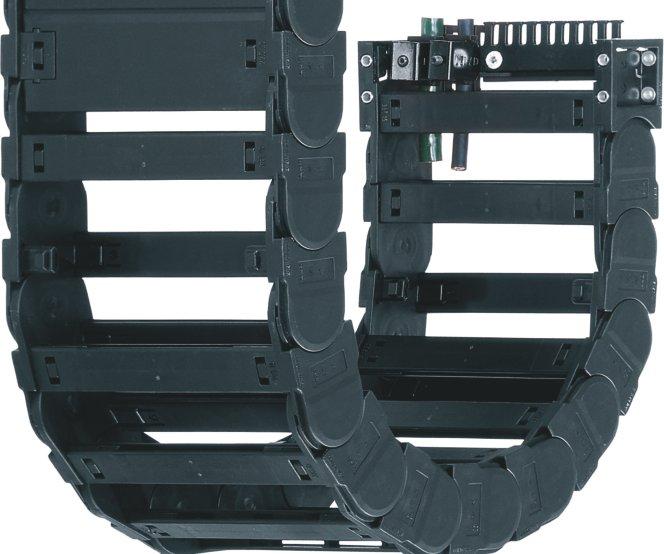
87 7.86
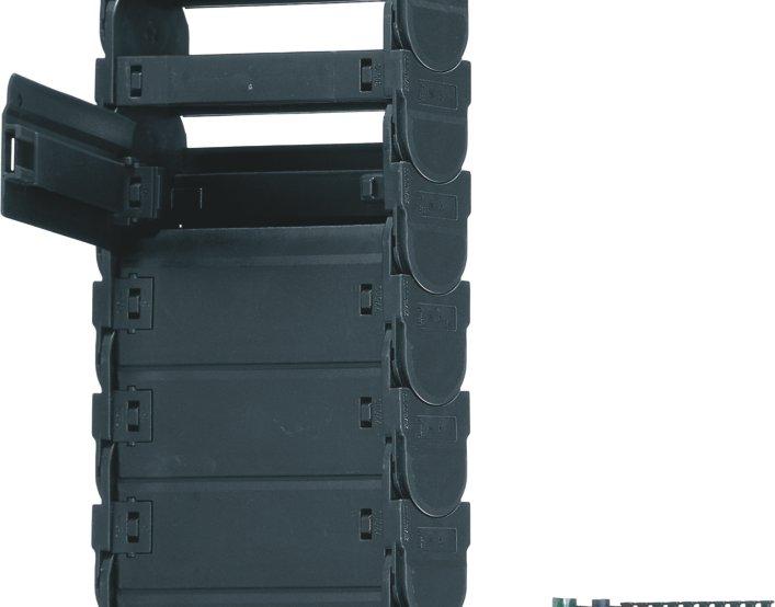
88 E4/4 7.87

89 E4/4 Side-mounted Travels over 200 m ugged stop dog igumid G -40/+120 C Outer link with rear catch - high stability "side-mounted" Lateral glide surfaces Best unsupported lengths "side-mounted" ol E-Chain links available For very long travels up to m High torsional rigidity Good for tough environments with dirt and debris ESD Version available Interior separation possibilities You can find more technical data about the material, chemical resistance, temperatures Design, from page 1.38 Opening-principle Can be opened from both sides Can be opened from both sides and hinged open on one side Dimensioning Bending radius structure Ba hi ha Bending radius Color black adius Width Series Selection table Series Inner height Inner width Outer width Outer height Bending radius Unsupported page hi [mm] [mm] Ba [mm] ha [mm] [mm] length max. [m] Crossbars every link - for particulary demanding applications , , , HD , , HD , Crossbars every other link - for almost all applications , , , , E-Tube - fully enclosed, excellent cable protection , , , HD , , HD ,
90 System E4/4 Selection chart E4/4 Comparison of the main characteristics hi m m [mm] [mm] [mm] max. [m] max. [kg/m] max. [m/s] [C ] kg C E4/4 E-Chain Crossbars every link C E4/4 E-Chain Crossbars every 2 nd link E4/4 E-Tube Fully enclosed ,0 6,0 6, C 3-40 C Unsupported length FL G = with straight upper run FL B = with permitted sag Inner heights from - to [mm] Inner widths from - to [mm] Bending radii from - to [mm] Unsupported lengths [m] Fill weights [kg/m] Speed max. FL G Speed max. FL B Gliding speed max. Long term temp. min/max. [ C] Additional quality features - System E4/4 Side-mounted - unsupported ATEX/ESD: Excellent performance with the special material igumid ESD (upon request) "ear grip" achieves long-term electrical conductivity High torsional rigidity System E4-4-piece E-Chain links System E4/4 proved with long travels Next Page: Find application examples and assembly instructions 7.89


 Typical industries & applications")


91 System E4/4 Applications System E4/4 (pronounced: E-4-4) come out to solve applications in two areas: The extreme long travels and the free-hanging side mounted situations. The famous tongue and groove between two links is one feature to make that possible. Push-forces and rigidity are increased - tolerance against dirt and debris rises. Special "ollerlinks" establishes E4/4 as the true long-travel specialist. The tongue and groove design also enables the excellent ESD/ATEX performance. The chain links are tightly linked to each other, so that electricity can flow through them when in contact with each other (Please note: This is valid only for the special conductive material igumid ESD and is not applicable for the standard series in this catalog) Typical industries & applications Cranes: TG, Quay cranes, many more Compost plants Gypsum plants, concrete plants, chemical plants Agricultural plants Mineral plants Machine tools: free-hanging-on-the-side applications Construction machinery ESD applications Heavy machinery Steel plants Shipyards Welding plants General machinery E4/4 - The "tongue-and-groove" design makes it the Series for "special cases" Special case: Side-mounted, unsupported - "tongue and groove" design offers stability Many successful ol E-Chain applications, i.e. one of the igus longest travels at the moment on 2 ship unloaders in Malaysia, both equipped with a ol E-Chain at 441,3 m travel length Special case: High lateral accelerations 200 m travels and more possible 7.90


92 System E4/4 Assembly Instructions E4/4 System E4/4 E-Chains and E-Tubes Assembling E-Chains Opening emove crossbars at connection point. Slide side links into each other - Press together Join the side links - join the second side link by pressing from the top emove crossbars - Insert screwdriver into the slot, push down, release by lever action Join the side links together on the opposite side by applying pressure to the outer link 5 Assemble crossbars - Push down and snap in by using a screwdriver 6 emove clips - Insert screwdriver into the slot and push down, release by lever action E-Tube Opening 1 Assemble clips (E-Chains with crossbars every other link) - Push down and snap in Assemble E-Tube lids/bottoms - Attach to the connector at an angle - Snap in System E4/4 E-Chains and E-Tubes Separating emove lids/bottoms - Insert screwdriver into the slot, release by lever action emove crossbars, clips, and lids on two adjacent chain links. Guide the screwdriver into the slot between side links and release it by levering it and separate the E-Chain elease only one side to swivel the lid You can find an assembly video on the web

93 E4/4 Price index Series 2828 Series 2928 Series 7728 Side-mounted - unsupported ESD classification: Electrically conductive ESD/ATEX version upon request High torsional rigidity System E4/4 Series High side-mount stability due to tongue and groove High torsional rigidity Crossbars on E-Chains are removable along both radii Closed and open styles can be combined emovable lids along inner radius Hinged snap-open removable lids along outer radius of E-Tube Lateral glide surfaces for side-mounted operation Wide, rounded plastic crossbars - cable friendly KMA mounting brackets with attachment points on all sides Locking or pivoting mounting brackets available E-Chain also available with reverse bending radii Opening E-Chains : emove crossbars and clips - Insert screwdriver into the slot, push down, release by lever action ol E-Chain Series 2828/7728 available upon request emove lids/bottoms (E-Tubes) - Insert screwdriver into the slot, release by lever action When to use the Series 2828/2928/7728: When high torsional or shearing forces are expected For side-mounted applications involving large unsupported lengths For long-term operation in very moist environments Also available as ol E-Chain Order example complete E-Chain Please indicate chain-lenghts or number of links Example: 3 m or 54 links When not to use it: If a quieter version is required Series 280/290/770, page m E-Chain with 2 separators 282 every 2 nd link Interior separation 1 set C Mounting bracket D-CAD files, pdf-downloads
94 E4/4 Series Dimensions and Technical Data Unsupported length FL G = with straight upper run FL B = with permitted sag Further information Design, page 1.12 HF H D S (FL G ) S (FL B ) FL G FL B S S/ Moving end Fixed end Unsupported length FL G / FL B [m] H D K D K H Fill weight [kg/m] Length of travel S [m] Pitch = 56 mm/link Links/m = 18 (1008 mm) Chain length = S / 2 + K H - 54 H H F = H + 40 S = Length of travel = Bending radius H = Nominal clearence height H F = equired clearence height H I = Trough inner height D = Overlength E-Chain radius in final position K = π + "safety" D 2 = Over length - long travels, gliding K 2 = *Further add-on H 2 = *Mounting height *if the mounting bracket location is set lower Other installation methods Vertical, hanging 70 m Vertical, standing 5 m Side mounted, unsupp. 2 m otary requires further calculation Unsupported length of upper run = upon request Short travels - unsupported Unsupported E-Chains feature positive camber over short travels. This must be accounted for when specifying the clearance height H F. Please consult igus if space is particularly restricted. The required clearance height: H F = H + 40 mm (with 2,0 kg/m fill weight) E4/4 32 System E4/4 Inner height: 32 mm Long travel lengths from 10 m to max. 200 m Chain length = S / 2 + K 2 S S/2 S/2 Moving end Fixed end H2 D2 K2 Guide trough with glide bar Guide trough without glide bar Total length of guide trough In case of travels between 4 and 10 m we recommend a longer unsupported length. HI Gliding, long travel applications (max. 200 m) In this case the E-Chain upper run will be introduced in a guide trough on the lower run. We recommend to realize the engineering of such a plant by our technicians. Speed / acceleration FL G max. 20 [m/s] / max. 200 [m/s 2 ] Speed / acceleration FL B max. 3 [m/s] / max. 6 [m/s 2 ] Gliding speed / acceleration (maximum) max. 10 [m/s] / max. 50 [m/s 2 ] Material - permitted temperature C igumid G / -40 up to +120 C Flammability class, igumid G VDE 0304 IIC UL94 HB Technical Data C Details of material properties page 1.38 page D-CAD files, pdf-downloads
95 E4/4 Ba System E4/4 Series Product ange Series E-Chain with crossbars every link igus E-ChainSystems 28 max. structure Color black Bending radius Crossbars every link For rigid hydraulic hoses For applications particularly demanding Can be opened from two sides Width Series 28 max. Ba structure Color black Bending radius Width Series Series E-Chain with crossbars every 2 nd link Crossbars every 2 nd link = Standard For nearly every situation Can be opened from two sides Easy assembly Stable Attractive price Ba Series Fully enclosed E-Tube Fully enclosed igus GmbH Cologne 28 max. structure Color black Bending radius Excellent cable protection against dirt Protection against hot chips (up to 900 C) Lids along the entire inner radius are completely removable. Lids along the entire outer radius are single sided snap-open with a hinge on the other side to keep them attached to the chain or completely removable. Width Series Internet: info@igus.de ol instead of gliding: ol E-Chain Special solution for long travels. 75% less drive power (gliding application) with igus ol E-Chain. Series Order example Further information: or phone: TIP! D-CAD files, pdf-downloads
96 System E4/4 Series Product ange Part.... No Ba [mm] [mm] [kg/m] [kg/m] [kg/m] 2828/2928/ * ,73 1,64 2, / ,79 1, /2928/ ,84 1,69 2, / ,93 1, /2928/ ,02 1,78 2, /2928/ ,08 1,81 2, / ,15 1, /2928/ ,20 1,87 3, / ,29 1, /2928/ ,38 1,96 3, / ,44 1, /2928/ ,51 2,02 3, / ,56 2, / ,65 2, /2928/ ,74 2,14 3, / ,87 2, / ,92 2, / ,05 2, /2928/ ,10 2,32 4, / ,19 2, / ,28 2, / ,37 2, /2928/ ,46 2,50 4, / ,59 2, / ,68 2, / ,77 2, / ,86 2, / ,95 2, / ,04 2, / ,11 2, / ,18 2,86 Available bending radii [mm] 063** 075** 100** Supplement with required radius. Example: = standard color, other colors page 1.39 Pitch = 56 mm/link - Links/m = 18 *emovable lid only, no hinged option **not available for 7728 TIP! Hot Chips up to 850 C E-Tubes that repel hot chips, up to 850 ºC Some applications, depending on amount and size of the chips, can burn or melt the surface. That is no longer the case with the new igus "igumid HT" material. Further information: or phone: Extender crossbar for large diameter hoses page E4/4 System E4/4 Inner height: 32 mm Single crossbar, E-Chain, 385. Single lid, E-Tube, 775. ight side link*, single part, E-Chain - links, single parts *View from the fixed point of the E-Chain /E-Tube Left side link*, single part, Single bottom, E-Tube, 776. page D-CAD files, pdf-downloads
97 E4/4 E4/4 Series Accessories Interior Separation igus E-ChainSystems Option 1 Vertical separators Spacers Locking separators Asymmetric separators E-Chain E-Tube 282A X T min.25 igus GmbH Cologne Internet: info@igus.de Vertical separator 281 Vertical separator 281T Vertical separator Vertical separator 283 Spacer Spacer Spacer Locking separator 293 Asymmetric separator 281A Vertical separator un Vertical separator for E-Tubes un T 282T Vertical separator /E-Tubes un Vertical separator un Spacer* un Spacer* un Spacer* un Locking separator un Asymmetric separator un *For side-mounted applications A 282A 2,5 12 2, ,5 14 2, ,5 10 2,5 2,75 12 Option 1: Vertical separators and spacers Vertical separators are used if a vertical subdivision of the E-Chain interior is required - By standard vertical separators are every other E-Chain link. Note: Observe a lateral spacing of at least 25 mm for E-Tubes! Standard separator 281 offers safe stability due to its wide base design, also when used with thick cables or hoses. If the distance needed between separators is greater than this separator s dimension, we offer the vertical separator The vertical separator 281T for E-Tubes clamps to the fixed radius and remains free along the other radius to facilitate lid removal. If installing these yourself, please ensure that they are identically aligned. If the distance needed between separators is greater than this separator s dimension, we offer the vertical separator Vertical separator 283 with a narrow base with applications where a large number of small cables need to be individually separated. Vertical separators in side-mounted applications, for instance, can be fixed in position by means of spacer 381.X. A wide range of intervals between the vertical separators is adjustable here. Note on spacers: The available interior height is reduced by 2 mm per spacer (4 mm when spacers are fitted on both sides). To avoid this, the parts can also be installed from the outside on the opening crossbar. Additionally: Locking separator with increased retention force for applications exposed to very high humidity or extreme loads. The extra retention force is achieved by asymmetric claws for the crossbar. Ensure proper alignment. Asymmetric separator 281A (not for E- Tubes) with an 12-mm base, for combinations between spacers of different widths and vertical separators in side-mounted applications, for instance D-CAD files, pdf-downloads
98 E4/4 Series Accessories Interior Separation E4/4 7 Option 2: Shelves X Side plate For applications involving many cables with different diameters. /E-Tubes The shelves can be arranged elevator-shifted with un 286 different bottoms Side plates 286, middle plates 288 and shelves 386.X Middle plate form the basic pattern of a shelf system. Shelves of various /E-Tubes widths can be arranged at 3 different heights (in 7 mm un 288 increments) For special applications: Vertical separator with injection 2,5 57,5 Vertical separator moulded shelf 281.S.57 (57,5 mm) or 281.S.45 (45 mm) /E-Tubes un 281.S.57 Slotted separators 291 (not for E-Tubes), are used for S.57 very fine subdivisions. However, they cannot be retrofitted into an existing separation system without dismantling the interior 2,5 45 Vertical separator separators first. /E-Tubes un 281.S.45 The unilateral open slotted separator 297 can be S.45 retrofitted into an existing interior separation system without a need for dismantling the interior separators. During an 3 Slotted separator installation of open slotted separators, the top and bottom notches cannot be occupied by shelves. un Option 2 Side plates Middle plates Vertical separators Slotted separators Open slotted separators Side plate 286 Middle plate 288 Vertical separator 281.S.57 Vertical separator 281.S.45 Slotted separator 291 System E4/4 Inner height: 32 mm 2,5 8 Open slotted separator /E-Tubes un Open slotted separator 297 Width X [mm] un Width X [mm] un Shelf 386.X Shelf X-8 4 page D-CAD files, pdf-downloads
99 E4/4 igus E-ChainSystems System E4/4 Series Product ange Extension links - for extremely wide E-Chains up to 3,0 m For applications in which particularly high fill weights necessitate extremely wide E-Chains (up to 3000 mm) The extension link design allows virtually limitless side-by-side attachment of chains The unsupported length of a chain can be increased when additional loads are required Extension links can be used with E-Chains, E-Tubes or as a combination of both They are suitable for unsupported and gliding applications in a guide trough E-Chains with extension links are attached with KMA or steel mounting brackets structure /20 / /2/ ,5 12, ± 3 ( ) + 13 ± 3 Extender crossbars - careful guide of hosed applications Suitable for hoses with a maximum outer diameter of 115 mm Gliding operation with crossbars along the outer radius and a special guide trough Gliding operation not guaranteed with crossbars along the inner radius The extender crossbar can either be attached to the side links directly or can be used in combination with two stranded snap-open crossbars ø 5,5 igus GmbH Cologne Consult igus for your extender crossbar applications. We are happy to assist you with your design layout HD115 round extender crossbar D115 round strap combined with snap-open crossbars directly on the side section Max Ø [mm] Form Installation Combination with hose side link snap-open crossb HD D = round + = yes / = no Hinged crossbars Typically E-Chain crossbars are completely removable. In cases where the snap-open crossbars have to remain at the open link of the E-Chain, a hinged design has been developed Length: 37,5 mm / snap-open crossbar (shortened): -37,5 mm Internet: info@igus.de ,5 mm Please consult igus for design assistance Option 1 Option 2 Option 3 Option 4 Ba Ba Ba Ba D-CAD files, pdf-downloads
100 E4/4 Series Accessories Mounting Brackets, KMA E4/4 The Standard - Option KMA* - pivoting ecommended for unsupported and gliding applications Confined installation conditions Option - integrated C-profile strain relief device with Chainfix clip or strain relief tiewrap plates Corrosion resistant Universal mountable with attachment capability on all sides *KMA = Polymer Metal Mounting Bracket Moving end 28280/ The attachment variants arising automatically by 45 Fixed end the choice of the KMA 28280/ mounting bracket Standard position C-profile Moving end Option KMA - locking ecommended for vertical hanging / standing applications Additionally: Universal mountable C-profile option Corrosion resistant Locked connections At very high acceleration 29280/ Fixed end 29280/ The attachment variants arising automatically by the choice of the KMA mounting bracket Standard position C-profile Fixed end Moving end 28280/ (pivoting) (pivoting) 28280/ / (locking) (locking) 29280/ Dimensions and order configurations structure (pivoting) C Optional with C-profile Full set Width = E-Chain = E-Tube structure (locking) 12,5 22,5 ø5,5 / t=7,2 Width full set C-profile index pivoting locking option [mm] / / C C / / C C / / C / / C C / / C C / / C C / / C C C / / C C ,5 12,5 Width full set C-profile index pivoting locking option [mm] C C / / C C C C / / C C C C C C C C C C Full set, for both ends: Single-part order:bei Optional with C-profile Full set Width = E-Chain = E-Tube Mounting bracket with bore Mounting bracket with pin page D-CAD files, pdf-downloads
101 15, E4/4 E4/4 Series Accessories Mounting Brackets, Steel Moving end Option steel - pivoting For pivoting connections One part (two-piece) for all chain widths Electrically conductive Possible installation conditions - Further installation angles installation sketch Fixed end Moving end Fixed end , igus GmbH Cologne Internet: info@igus.de Full set, 4 parts 2 with pin / 2 with bore Single-part order: Mounting bracket with bore, 1 part left / right Mounting bracket with pin, 1 part left / right Other strain relief elements chapter 10 For E-Chain full set [mm] For E-Chain full set [mm] D-CAD files, pdf-downloads
102 2 8 6 E4/4 Series Accessories Strain elief Chainfix clamps for the C-profile single clamps double clamps triple clamps Cable steel stainless steel steel stainless steel steel stainless steel ø [mm] CFX12.1 CFX12.1.E CFX12.2 CFX12.2.E CFX CFX14.1 CFX14.1.E CFX14.2 CFX14.2.E CFX CFX16.1 CFX16.1.E CFX16.2 CFX16.2.E CFX CFX18.1 CFX18.1.E CFX18.2 CFX18.2.E CFX CFX20.1 CFX20.1.E CFX20.2 CFX20.2.E CFX CFX22.1 CFX22.1.E CFX22.2 CFX22.2.E CFX CFX26.1 CFX26.1.E CFX26.2 CFX26.2.E CFX30.1 CFX30.1.E CFX30.2 CFX30.2.E CFX34.1 CFX34.1.E CFX34.2 CFX34.2.E CFX38.1 CFX38.1.E CFX42.1 CFX42.1.E igus Chainfix steel clamps and Chainfix stainless-steel clamps - max. pull forces, adjustable with hexagon socket. Available as single, double or triple clamps. Details chapter E4/4 System E4/4 Inner height: 32 mm Cable ø [mm] clamp bottom part CFC-08-M CFC-08-C CFC-12-M CFC-12-C CFC-16-M CFC-16-C CFC-20-M CFC-20-C CFC-24-M CFC-24-C ø max. Width conduit [mm] [mm] CFN ,8 Chainfix Clip - Modular snap-on strain relief device for C-profile Available for all igus E-ChainSystems with C- profiles and also suitable for assembly in the KMA mounting brackets and clip-on strain relief for crossbars. High pull forces, plug-in modular snapon strain relief device. Details chapter 10 Chainfix Nugget for the C-Profil Strain relief for the fixation of cables up to a diameter of Ø 20 mm. Easy to assemble, without any screws and tools. Easy strain relief due to fixation with preharnessed cable strap, very small space requirement. Details chapter 10 Width of Number strain relief [mm] of teeth 3050.ZC ZC 75 7 Chainfix tiewrap plates with clip-on connection for the C-profile Can be plugged into the KMA C-profile. Easy to assemble without any screws. Easily solvable with screwdriver nevertheless safe stop. For all E-Chains with KMA and integrated C-profile. Details chapter 10 Tiewrap No. of Dim. C Dim. B Center plate teeth n [mm] [mm] bore 3050.ZB ZB ZB ZB ZB ZB ZB ZB ZB ZB ( = no / + = yes) 6.2 Tiewrap plate as individual part As individual component screwed on KMA. Can be plugged in the mounting brackets. Details chapter 10 C B 2 8 (n-1) x 10 Details about all strain relief option for this series chapter 10 12/ Single tiewrap plate Shown Chapter 10 page
103 E4/4 Ba = Outer width E-Chains / E-Tube = Inner width E-Chains / E-Tube ha = Outer height E-Chains / E-Tube H i = Inner trough height H a = Outer trough height B i = Inner trough width depends on dim. Ba B a = Outer trough width n Mon = Number of installation sets (left/right) n i = Number of troughs sets (left/right)! igus GmbH Cologne Internet: info@igus.de H i 2 ha B i Ba + 4 = Guide trough set = Glide bar = Installation set "Basic" = C-profile Installation set "Basic" with C-profile Bottom Clamp attached optionally inwards or outwards Order example B i attached attached [mm] inwards outwards Insert for the installation set "Heavy-Duty": XXX instead of XXX on the right column "attached outwards" SL SL Trough height: 117 mm Aluminum "SuperTrough" Basic Version Bottom clamp attached optionally inwards or outwards n Mon = n i + 1 M6 x16 B a B i Ba + 4 Ba ha ,9 Length of the C-profile according to dimension B i n i x 2000 mm 27 see table H i 2 x ha H a = 117 Components, trough "Basic": Trough side parts, aluminum, 2 m Glide bar, plastic, 2 m Glide strips, plastic, 2 m (without glide strips on request) Optional: Silencer profile, rubber Components, installation set "Basic": Bottom clamp, aluminum C-profile, steel galvanized Screw M6 x16 Sliding nut M6 Interface connector, plastic Order example: Length of travel 30 m - Center mounted for Series with B i = 328 Guide trough set (set of 2 trough side parts, incl. glide strips) without glide bar Order text: 16 m guide trough without glide bar (8 x 2 m sections) Guide trough set (set of 2 trough side parts, incl. glide strips) with glide bar Order text: 16 m guide trough with glide bar (8 x 2 m sections) Installation set "Basic" complete (guide trough-sets + 1) Order text: 17 installation sets "Basic" Module for the fixed end Order text: 1 set Option: For an additional noise dampening with silencer profile, please add Index A - Example: SL SL SLA Principle sketch: Number of installation sets to be installed = Number of trough sections + 1 Details about Alu "SuperTrough" and further guidance possibilities NEW! A quick fix for mounting the stationary end of an E-Chain With this new module for the fixed end, fast and easy mounting onto the Aluminum "SuperTrough" is now possible without any drilling. Fast mounting of the E-Chain by clamping onto the aluminum trough Quick relocation of the stationary end No drilling necessary page 9.16 chapter 9, Guide Troughs
104 My Sketches E4/4 System E4/4 Inner height: 32 mm TPE-Power cable for high dynamic - Chainflex CF35 TPE-Outer jacket, oil- and bio-oil-resistant, flame retardant, shielded Further information: igus chainflex CF35 TIP! Chapter 9 page D-CAD files, pdf-downloads

105 E4/4 Price index Series 3838 Series 3938 Series 7838 Side-mounted - unsupported ESD classification: Electrically conductive ESD/ATEX version upon request High torsional rigidity System E4/4 Series High side-mount stability due to tongue and groove High torsional rigidity Closed and open styles can be combined Hinged snap-open removable lids along outer radius of E-Tube emovable lids along inner radius Crossbars on E-Chains are removable along both radii Lateral glide surfaces for side-mounted operation Wide, rounded plastic crossbars - cable friendly KMA mounting brackets with attachment points on all sides Locking or pivoting mounting brackets available E-Chain also available with reverse bending radii Opening E-Chains : emove crossbars and clips - Insert screwdriver into the slot, push down, release by lever action ol E-Chain Series 3838/7838 available upon request emove lids/bottoms (E-Tubes) - Insert screwdriver into the slot, release by lever action When to use the Series 3838/3938/7838: When high torsional or shearing forces are expected For side-mounted applications involving large unsupported lengths For long-term operation in very moist environments Also available as ol E-Chain When not to use it: If a quieter version is required Series 380/390/ 780, page 7.36 For increased inner height of 52 mm Series , page Order example complete E-Chain Please indicate chain-lenghts or number of links Example: 4 m or 60 links 4 m E-Chain with 2 separators 382 every 2 nd link Interior separation 1 set C Mounting bracket D-CAD files, pdf-downloads
106 E4/4 Series Dimensions and Technical Data Unsupported length FL G = with straight upper run FL B = with permitted sag Further information Design, page 1.12 HF H D S (FL G ) S (FL B ) FL G FL B S S/ Moving end Fixed end FL G FL B Unsupported length FL G / FL B [m] Length of travel S [m] Pitch = 67 mm/link Links/m = 15 (1005 mm) Chain length = S / 2 + K H D K D K H Fill weight [kg/m] H - 64 H H F = H + 40 S = Length of travel = Bending radius H = Nominal clearence height H F = equired clearence height H I = Trough inner height D = Overlength E-Chain radius in final position K = π + "safety" D 2 = Over length - long travels, gliding K 2 = *Further add-on H 2 = *Mounting height *if the mounting bracket location is set lower Other installation methods Vertical, hanging 100 m Vertical, standing 6 m Side mounted, unsupp. 2,5 m otary requires further calculation Unsupported length of upper run = upon request Short travels - unsupported Unsupported E-Chains feature positive camber over short travels. This must be accounted for when specifying the clearance height H F. Please consult igus if space is particularly restricted. The required clearance height: H F = H + 40 mm (with 2,0 kg/m fill weight) E4/4 42 System E4/4 Inner height: 42 mm Long travel lengths from 10 m to max. 280 m Chain length = S / 2 + K 2 S S/2 S/2 Moving end Fixed end H2 D2 K2 Guide trough with glide bar Guide trough without glide bar Total length of guide trough In case of travels between 4 and 10 m we recommend a longer unsupported length. HI Gliding, long travel applications (max. 280 m) In this case the E-Chain upper run will be introduced in a guide trough on the lower run. We recommend to realize the engineering of such a plant by our technicians. Speed / acceleration FL G max. 20 [m/s] / max. 200 [m/s 2 ] Speed / acceleration FL B max. 3 [m/s] / max. 6 [m/s 2 ] Gliding speed / acceleration (maximum) max. 10 [m/s] / max. 50 [m/s 2 ] Material - permitted temperature C igumid G / -40 up to +120 C Flammability class, igumid G VDE 0304 IIC UL94 HB Technical Data C Details of material properties page 1.38 page D-CAD files, pdf-downloads
107 E4/4 Ba System E4/4 Series Product ange Series E-Chain with crossbars every link igus E-ChainSystems 38 max. structure Color black Bending radius Crossbars every link For rigid hydraulic hoses For applications particularly demanding Can be opened from two sides Width Series 38 max. Ba structure Color black Bending radius Width Series Series E-Chain with crossbars every 2 nd link Crossbars every 2 nd link = Standard For nearly every situation Can be opened from two sides Easy assembly Stable Attractive price Ba Series Fully enclosed E-Tube Fully enclosed igus GmbH Cologne 38 max. structure Color black Bending radius Excellent cable protection against dirt Protection against hot chips (up to 900 C) Lids along the entire inner radius are completely removable. Lids along the entire outer radius are single sided snap-open with a hinge on the other side to keep them attached to the chain or completely removable. Width Series Internet: info@igus.de ol instead of gliding: ol E-Chain Special solution for long travels. 75% less drive power (gliding application) with igus ol E-Chain. Series Order example Further information: or phone: TIP! D-CAD files, pdf-downloads
108 System E4/4 Series Product ange Part.... No Ba [mm] [mm] [kg/m] [kg/m] [kg/m] 3838/3938/ * ,06 1,98 2, / ,09 1, /3938/ ,12 2,01 2, / ,18 2, /3938/ ,25 2,08 2, /3938/ ,30 2,10 2, / ,30 2, /3938/ ,40 2,15 2, / ,44 2, /3938/ ,53 2,21 3, / ,55 2, /3938/ ,62 2,26 3, / ,62 2, / ,69 2, /3938/ ,77 2,33 3, / ,84 2, / ,92 2, / ,96 2, /3938/ ,05 2,47 4, / ,06 2, / ,17 2, / ,19 2, /3938/ ,32 2,61 4, / ,34 2, / ,41 2, / ,46 2, / ,68 2, / ,74 2, / ,79 2, / ,85 2, / ,90 2,90 igus Line Extension TIP! Hot Chips up to 850 C E-Tubes that repel hot chips, up to 850 ºC Some applications, depending on amount and size of the chips, can burn or melt the surface. That is no longer the case with the new igus "igumid HT" material. Further information: or phone: TIP! Increased inner height 52 mm The Series E- Chain, with an increased inner height of 52 mm, is available for unsupported applications page E4/4 System E4/4 Inner height: 42 mm Available bending radii [mm] 075** 100** 115** Supplement with required radius. Example: = standard color, other colors page 1.39 Pitch = 67 mm/link - Links/m = 15 *emovable lid only, no hinged option **not available for 7838 Extender crossbar for large diameter hoses page Single crossbar, E-Chain, 385. Single lid, E-Tube, 785. ight side link*, single part, E-Chain - links, single parts *View from the fixed point of the E-Chain /E-Tube ight side link*, single part, Single bottom, E-Tube, 786. page D-CAD files, pdf-downloads
109 E4/4 E4/4 Series Accessories Interior Separation igus E-ChainSystems Option 1 Vertical separators Spacers Locking separators Asymmetric separators E-Chain E-Tube 382A X T 384 min.25 igus GmbH Cologne Vertical separator 381 Vertical separator with a narrow base 3881 Vertical separator 381T Spacer Spacer Spacer Vertical separator un Vertical separator un Vertical separator for E-Tubes un 381T 382T Spacer* un Spacer* un Spacer* un ,5 14 2, Option 1: Vertical separators and spacers Vertical separators are used if a vertical subdivision of the E-Chain interior is required - By standard vertical separators are every other E-Chain link. Note: Observe a lateral spacing of at least 25 mm for E-Tubes! Standard separator 381 offers safe stability due to its wide base design, also when used with thick cables or hoses. Vertical separator 3881 with a narrow base (7 mm) for E- Chains with applications where a large number of small cables need to be individually separated. Vertical separator 381T for E-Tubes clamps to the fixed radius and remains free along the other radius to facilitate lid removal. If installing these yourself, please ensure that they are identically aligned. Vertical separators in side-mounted applications, for instance, can be fixed in position by means of spacer 381.X. A wide range of intervals between the vertical separators is adjustable here. Note on spacers: The available interior height is reduced by 2 mm per spacer (4 mm when spacers are fitted on both sides). To avoid this, the parts can also be installed from the outside on the opening crossbar. Internet: info@igus.de Locking separator 3804 Locking separator 383 Asymmetric separator 381A Locking separator un Locking separator for E-Tubes un Asymmetric separator un *For side-mounted applications A 382A 2,5 14 2,5 10 2,5 2,75 14 Additionally: Locking separator with increased retention force for applications exposed to very high humidity or extreme loads. The extra retention force is achieved by asymmetric claws for the crossbar. Ensure proper alignment. Locking separator 383 for E-Tubes - This vertical separator is suitable for use in extremely moist environments. Asymmetric separator 381A (not for E- Tubes) with an 14-mm base, for combinations between spacers of different widths and vertical separators in side-mounted applications, for instance D-CAD files, pdf-downloads

110 E4/4 Series Accessories Interior Separation E4/ Option 2: Shelves X For applications involving many cables with different diameters. The shelves can be arranged elevator-shifted with different bottoms. Side plates 386, middle plates 388 and shelves 386.X form the basic pattern of a shelf system. Shelves of various widths can be arranged at 5 different heights (in 7 mm increments). Slotted separators 391are used for very fine subdivisions. However, they cannot be retrofitted into an existing separation system without dismantling the interior separators first. The unilateral open slotted separator 397 can be retrofitted into an existing interior separation system without a need for dismantling the interior separators. During an installation of open slotted separators, the top and bottom notches cannot be occupied by shelves ,5 10 Side plate /E-Tubes un Middle plate /E-Tubes un Slotted separator /E-Tubes un Open slotted separator /E-Tubes un Option 2 Side plates Middle plates Slotted separators Open slotted separators Side plate 386 Middle plate 388 Slotted separator 391 Open slotted separator 397 System E4/4 Inner height: 42 mm Width X [mm] un Width X [mm] un Shelf 386.X Shelf X-8 4 page D-CAD files, pdf-downloads
 The extension link design allows virtually limitless side-by-side attachment of chains The unsupported length of a chain can be increased")
111 E4/4 igus E-ChainSystems System E4/4 Series Product ange Extension links - for extremely wide E-Chains up to 3,0 m For applications in which particularly high fill weights necessitate extremely wide E-Chains (up to 3000 mm) The extension link design allows virtually limitless side-by-side attachment of chains The unsupported length of a chain can be increased when additional loads are required Extension links can be used with E-Chains, E-Tubes or as a combination of both They are suitable for unsupported and gliding applications in a guide trough E-Chains with extension links are attached with KMA or steel mounting brackets structure /20 / /2/ , , ± 3 ( ) + 16 ± 3 Extender crossbars - careful guide of hosed applications Suitable for hoses with a maximum outer diameter of 115 mm Gliding operation with crossbars along the outer radius and a special guide trough Gliding operation not guaranteed with crossbars along the inner radius The extender crossbar can either be attached to the side links directly or can be used in combination with two stranded snap-open crossbars ø 5,5 igus GmbH Cologne Consult igus for your extender crossbar applications. We are happy to assist you with your design layout HD115 round extender crossbar D115 round strap combined with snap-open crossbars directly on the side section Max Ø [mm] Form Installation Combination with hose side link snap-open crossb HD D = round + = yes / = no Hinged crossbars Typically E-Chain crossbars are completely removable. In cases where the snap-open crossbars have to remain at the open link of the E-Chain, a hinged design has been developed Length: 37,5 mm / snap-open crossbar (shortened): -37,5 mm Internet: info@igus.de ,5 mm Please consult igus for design assistance Option 1 Option 2 Option 3 Option 4 Ba Ba Ba Ba D-CAD files, pdf-downloads
112 E4/4 Series Accessories Mounting Brackets, KMA E4/4 The Standard - Option KMA* - pivoting ecommended for unsupported and gliding applications Confined installation conditions Option - integrated C-profile strain relief device with Chainfix clip or strain relief tiewrap plates Corrosion resistant Universal mountable with attachment capability on all sides *KMA = Polymer Metal Mounting Bracket Moving end 38380/ The attachment variants 45 arising automatically by Fixed end the choice of the KMA 38380/ mounting bracket Standard position C-profile Moving end Option KMA - locking ecommended for vertical hanging / standing applications Additionally: Universal mountable C-profile option Corrosion resistant Locked connections At very high acceleration 39380/ Fixed end 39380/ The attachment variants arising automatically by the choice of the KMA mounting bracket Standard position C-profile Fixed end Moving end 38380/ (pivoting) (pivoting) 38380/ / (locking) (locking) 39380/ Dimensions and order configurations structure (pivoting) C Optional with C-profile Full set Width = E-Chain = E-Tube 15 22,5 ø6,5 / t=8,2 22,5 15 Width full set C-profile index pivoting locking option [mm] / / C C / / C C / / C / / C C / / C C / / C C / / C C C / / C C 212 Width full set C-profile index pivoting locking option [mm] C C / / C C C C / / C C C C C C C C C 400 structure (locking) C Full set, for both ends: Single-part order:bei Optional with C-profile Full set Width = E-Chain = E-Tube Mounting bracket with bore Mounting bracket with pin page D-CAD files, pdf-downloads
113 E4/4 E4/4 Series Accessories Mounting Brackets, Steel Moving end Option steel - pivoting For pivoting connections One part (two-piece) for all chain widths Electrically conductive Possible installation conditions - Further installation angles installation sketch Fixed end Moving end Fixed end ,5 igus GmbH Cologne Internet: info@igus.de Full set, 4 parts 2 with pin / 2 with bore Single-part order: Mounting bracket with bore, 1 part left / right Mounting bracket with pin, 1 part left / right Other strain relief elements chapter 10 For E-Chain full set [mm] For E-Chain full set [mm] D-CAD files, pdf-downloads
114 2 8 6 E4/4 Series Accessories Strain elief Chainfix clamps for the C-profile single clamps double clamps triple clamps Cable steel stainless steel steel stainless steel steel stainless steel ø [mm] CFX12.1 CFX12.1.E CFX12.2 CFX12.2.E CFX CFX14.1 CFX14.1.E CFX14.2 CFX14.2.E CFX CFX16.1 CFX16.1.E CFX16.2 CFX16.2.E CFX CFX18.1 CFX18.1.E CFX18.2 CFX18.2.E CFX CFX20.1 CFX20.1.E CFX20.2 CFX20.2.E CFX CFX22.1 CFX22.1.E CFX22.2 CFX22.2.E CFX CFX26.1 CFX26.1.E CFX26.2 CFX26.2.E CFX30.1 CFX30.1.E CFX30.2 CFX30.2.E CFX34.1 CFX34.1.E CFX34.2 CFX34.2.E CFX38.1 CFX38.1.E CFX42.1 CFX42.1.E igus Chainfix steel clamps and Chainfix stainless-steel clamps - max. pull forces, adjustable with hexagon socket. Available as single, double or triple clamps. Details chapter E4/4 System E4/4 Inner height: 42 mm Cable ø [mm] clamp bottom part CFC-08-M CFC-08-C CFC-12-M CFC-12-C CFC-16-M CFC-16-C CFC-20-M CFC-20-C CFC-24-M CFC-24-C ø max. Width conduit [mm] [mm] CFN ,8 Chainfix Clip - Modular snap-on strain relief device for C-profile Available for all igus E-ChainSystems with C- profiles and also suitable for assembly in the KMA mounting brackets and clip-on strain relief for crossbars. High pull forces, plug-in modular snapon strain relief device. Details chapter 10 Chainfix Nugget for the C-Profil Strain relief for the fixation of cables up to a diameter of Ø 20 mm. Easy to assemble, without any screws and tools. Easy strain relief due to fixation with preharnessed cable strap, very small space requirement. Details chapter 10 Width of Number strain relief [mm] of teeth 3050.ZC ZC 75 7 Chainfix tiewrap plates with clip-on connection for the C-profile Can be plugged into the KMA C-profile. Easy to assemble without any screws. Easily solvable with screwdriver nevertheless safe stop. For all E-Chains with KMA and integrated C-profile. Details chapter 10 Tiewrap No. of Dim. C Dim. B Center plate teeth n [mm] [mm] bore 3050.ZB ZB ZB ZB ZB ZB ZB ZB ZB ZB ( = no / + = yes) 6.2 Tiewrap plate as individual part As individual component screwed on KMA. Can be plugged in the mounting brackets. Details chapter 10 C B 2 8 (n-1) x 10 Details about all strain relief option for this series chapter 10 12/ Single tiewrap plate Shown Chapter 10 page
115 E4/4 Ba = Outer width E-Chains / E-Tube = Inner width E-Chains / E-Tube ha = Outer height E-Chains / E-Tube H i = Inner trough height H a = Outer trough height B i = Inner trough width depends on dim. Ba B a = Outer trough width n Mon = Number of installation sets (left/right) n i = Number of troughs sets (left/right)! igus GmbH Cologne Internet: info@igus.de H i 2 ha B i Ba + 4 = Guide trough set = Glide bar = Installation set "Basic" = C-profile Installation set "Basic" with C-profile Bottom Clamp attached optionally inwards or outwards Order example B i attached attached [mm] inwards outwards Insert for the installation set "Heavy-Duty": XXX instead of ( XXX) on the right column "attached outwards" SL SL Trough height: 144 mm Aluminum "SuperTrough" Basic Version Bottom clamp attached optionally inwards or outwards n Mon = n i + 1 M8 x20 B a B i Ba + 4 Ba Details about Alu "SuperTrough" and further guidance possibilities ha 64 18,4 8 Length of the C-profile according to dimension B i n i x 2000 mm 45 see table H i 2 x ha H a = 144 Components, trough "Basic": Trough side parts, aluminum, 2 m Glide bar, plastic, 2 m Glide strips, plastic, 2 m (without glide strips on request) Optional: Silencer profile, rubber Components, installation set "Basic": Bottom clamp, aluminum C-profile, steel galvanized Screw M8 x20 Sliding nut M8 Interface connector, plastic Order example: Length of travel 30 m - Center mounted for Series with B i = 231 Guide trough set (set of 2 trough side parts, incl. glide strips) without glide bar Order text: 16 m guide trough without glide bar (8 x 2 m sections) Guide trough set (set of 2 trough side parts, incl. glide strips) with glide bar Order text: 16 m guide trough with glide bar (8 x 2 m sections) Installation set "Basic" complete (guide trough-sets + 1) Order text: 17 installation sets "Basic" Module for the fixed end Order text: 1 set Option: For an additional noise dampening with silencer profile, please add Index A - Example: SL SL SLA Principle sketch: Number of installation sets to be installed = Number of trough sections + 1 NEW! A quick fix for mounting the stationary end of an E-Chain With this new module for the fixed end, fast and easy mounting onto the Aluminum "SuperTrough" is now possible without any drilling. Fast mounting of the E-Chain by clamping onto the aluminum trough Quick relocation of the stationary end No drilling necessary page 9.16 chapter 9, Guide Troughs
116 My Sketches E4/4 System E4/4 Inner height: 42 mm TPE-Control cable for low-temperature applications - Chainflex CF10 TPE-outer jacket, oil- and bio-oil-resistant, PVC- and halogen-free, low-temperature-flexible Further information: igus chainflex CF10 TIP! Chapter 9 page D-CAD files, pdf-downloads
117 E4/4 Price index Series 4040 Series 4140 Series 8840 Side-mounted - unsupported ESD classification: Electrically conductive ESD/ATEX version upon request High torsional rigidity System E4/4 Series ! High side-mount stability due to tongue and groove High torsional rigidity Closed and open styles can be combined Hinged snap-open removable lids of E-Tube Numerous interior separation possibilities Crossbars on E-Chains are removable along both radii Lateral glide surfaces for side-mounted operation Wide, rounded plastic crossbars - cable friendly KMA mounting brackets with attachment points on all sides Mounting brackets with integrated strain relief available, locking or pivoting E-Chains also available with reverse bending radius "B" New "Heavy-Duty" size available. Greater unsupported length for higher loads and travels. Also available as ol E-Chain version Opening E-Chains : emove crossbars and clips - Insert screwdriver into the slot, push down, release by lever action ol E-Chain Series 4040/8840 available upon request emove lids/bottoms (E-Tubes) - Insert screwdriver into the slot, release by lever action When to use the Series 4040/4140/8840: When high torsional forces are expected For side-mounted applications involving large unsupported lengths For long-term operation in very moist environments Also available as ol E-Chain When not to use it: If a quieter version is required Series 400/410/880, page 7.48 If a simple and low-cost solution is required Series 14040/18840, page When very long travels or high additional loads are involved Series 4040HD, page Order example complete E-Chain Please indicate chain-lenghts or number of links Example: 5 m or 55 links 5 m E-Chain with 2 separators 411 every 2 nd link Interior separation 1 set C Mounting bracket D-CAD files, pdf-downloads
118 E4/4 Series Dimensions and Technical Data Unsupported length FL G = with straight upper run FL B = with permitted sag Further information Design, page 1.12 HF H D S (FL G ) S (FL B ) FL G FL B S S/2 Fixed end Moving end FL G FL B Unsupported length FL G / FL B [m] Length of travel S [m] Pitch = 91 mm/link Links/m = 11 (1001 mm) Chain length = S / 2 + K H D K D K H Fill weight [kg/m] H - 84 H H F = H + 50 S = Length of travel = Bending radius H = Nominal clearence height H F = equired clearence height H I = Trough inner height D = Overlength E-Chain radius in final position K = π + "safety" D 2 = Over length - long travels, gliding K 2 = *Further add-on H 2 = *Mounting height *if the mounting bracket location is set lower Other installation methods Vertical, hanging 100 m Vertical, standing 6 m Side mounted, unsupp. 3 m otary requires further calculation Unsupported length of upper run = upon request Short travels - unsupported Unsupported E-Chains feature positive camber over short travels. This must be accounted for when specifying the clearance height H F. Please consult igus if space is particularly restricted. The required clearance height: H F = H + 50 mm (with 3,0 kg/m fill weight) E4/4 56 System E4/4 Inner height: 56 mm Long travel lengths from 10 m to max. 300 m Chain length = S / 2 + K 2 S S/2 S/2 Moving end Fixed end H2 D2 K2 Guide trough with glide bar Guide trough without glide bar Total length of guide trough In case of travels between 4 and 10 m we recommend a longer unsupported length. HI Gliding, long travel applications (max. 300 m) In this case the E-Chain upper run will be introduced in a guide trough on the lower run. We recommend to realize the engineering of such a plant by our technicians. Speed / acceleration FL G max. 20 [m/s] / max. 200 [m/s 2 ] Speed / acceleration FL B max. 3 [m/s] / max. 6 [m/s 2 ] Gliding speed / acceleration (maximum) max. 10 [m/s] / max. 50 [m/s 2 ] Material - permitted temperature C igumid G / -40 up to +120 C Flammability class, igumid G VDE 0304 IIC UL94 HB Technical Data C Details of material properties page 1.38 page D-CAD files, pdf-downloads
119 E4/4 Ba System E4/4 Series Product ange Series E-Chain with crossbars every link igus E-ChainSystems 50 max. structure Color black Bending radius Crossbars every link For rigid hydraulic hoses For applications particularly demanding Can be opened from two sides Width Series 50 max. Ba structure Color black Bending radius Width Series Series E-Chain with crossbars every 2 nd link Crossbars every 2 nd link = Standard For nearly every situation Can be opened from two sides Easy assembly Stable Attractive price Ba Series Fully enclosed E-Tube Fully enclosed igus GmbH Cologne 50 max. structure Color black Bending radius Excellent cable protection against dirt Protection against hot chips (up to 900 C) Lids along the entire inner radius are completely removable. Lids along the entire outer radius are single sided snap-open with a hinge on the other side to keep them attached to the chain or completely removable. Width Series Internet: info@igus.de ol instead of gliding: ol E-Chain Special solution for long travels. 75% less drive power (gliding application) with igus ol E-Chain. Series Order example Further information: or phone: TIP! D-CAD files, pdf-downloads
120 System E4/4 Series Product ange Part... No Ba [mm] [mm] [kg/m] [kg/m] [kg/m] 4040/4140/ ,65 3, /4140/ ,67 3, /4140/ * ,78 3,70 4, /4140/ ,96 3,78 4, / ,09 3, /4140/ ,16 3,88 4, / ,29 3, /4140/ ,36 3,98 5, / ,47 4, / ,58 4, / ,69 4, /4140/ ,71 4,16 5, / ,82 4, / ,88 4, / ,02 4, /4140/ ,10 4,36 6, / ,19 4, /4140/ ,30 4,46 6, / ,32 4, /4140/ ,54 4,58 7, / ,58 4, / ,63 4, / ,81 4, /4140/ ,96 4,79 8, / ,96 4, / ,98 4, / ,07 4, /4140/ ,27 4,94 8, / ,42 5, / ,58 5, / ,64 5, / ,71 5, /4140/ ,73 5,19 9, / ,86 5, / ,88 5, / ,00 5, / ,02 5, / ,06 5, / ,22 5, / ,70 5, / ,90 5,75 Available bending radii [mm] 135** Supplement with required radius. Example: = standard color, other colors page 1.39 Pitch = 91 mm/link - Links/m = 11 *emovable lid only, no hinged option **not available for 8840 Single crossbar, E-Chain, 450. Single lid, E-Tube, 885. ight side link*, single part, Extreme Glider... with up to 70% larger glide surface. For high additional loads and high gliding speeds. Gliding applications without additional elements as well as 150% more wear allowance and improvement of service life by factor 4! Order example: G G Further information: phone Extender crossbar for large diameter hoses page E-Chain - links, single parts *View from the fixed point of the E-Chain /E-Tube TIP! Hot Chips up to 850 C E-Tubes that repel hot chips, up to 850 ºC Some applications, depending on amount and size of the chips, can burn or melt the surface. That is no longer the case with the new igus "igumid HT" material. Further information: or phone: TIP! E4/4 System E4/4 Inner height: 56 mm Left side link*, single part, D-CAD files, pdf-downloads Single bottom, E-Tube, page
121 E4/4 E4/4 Series Accessories Interior Separation igus E-ChainSystems Option 1 Vertical separators Spacers Locking separators Asymmetric separators E-Chain min.16 E-Tube 411A 415.X min.33 Vertical separator 401 Vertical separator 483 Spacer Spacer Vertical separator /E-Tubes un Vertical separator /E-Tubes un Spacer* un Spacer* un Option 1: Vertical separators and spacers Vertical separators are used if a vertical subdivision of the E-Chain interior is required - By standard vertical separators are every other E-Chain link. Note: Observe a lateral spacing of at least 16 mm and at least 33 mm for E-Tubes! Standard separator 401 and E-Tubes offers safe stability due to its wide base design, also when used with thick cables or hoses. Vertical separator 483 with a narrow base and E-Tubes with applications where a large number of small cables need to be individually separated. Vertical separators in side-mounted applications, for instance, can be fixed in position by means of spacer 405.X. A wide range of intervals between the vertical separators is adjustable here. igus GmbH Cologne Internet: info@igus.de Spacer Spacer Spacer Locking separator 404 Asymmetric separator 401A Spacer* un Spacer* un Spacer* un Locking separator un Asymmetric separator un 401A 411A *For side-mounted applications ,5 18 Note on spacers: The available interior height is reduced by 2 mm per spacer (4 mm when spacers are fitted on both sides). To avoid this, the parts can also be installed from the outside on the opening crossbar. Additionally: Locking separator with increased retention force for applications exposed to very high humidity or extreme loads. The extra retention force is achieved by asymmetric claws for the crossbar. Ensure proper alignment. Locking separator 406 for E4-Tubes - safe fitting locked on lid or bottom of the Tube and sideways slideable. The opposing lid or bottom can easily be opened and closed. Especially capable if many separators need to be on a tight inner width. Art. Nr. not Art. Nr For illustration, refer to vertical separator 404. Asymmetric separator 401A (not for E- Tubes) with an 18-mm base, for combinations between spacers of different widths and vertical separators in side-mounted applications, for instance D-CAD files, pdf-downloads
122 E4/4 Series Accessories Interior Separation E4/ X Option 2 Option 2: Shelves Side plate 7 Side plates Middle plates Locking vertical separator Slotted separators Open slotted separators System E4/4 Inner height: 56 mm For applications involving many cables with different dia- /E-Tubes Side plate meters. The shelves can be arranged elevator-shifted with un different bottoms. Side plates 402, middle plates 403 and shelves 420.X form the basic pattern of a shelf system. Shelves of various widths can be arranged at 7 different heights (in 7 mm increments). Locking vertical separator 410, slotted combined with shelves. Slotted separators 408 are used for very fine subdivisions. However, they cannot be retrofitted into an existing separation system without dismantling the interior separators first Middle plate /E-Tubes un Locking vertical separator /E-Tubes un Slotted separator Middle plate 403 Locking vertical separator 410 The unilateral open slotted separator 409 can be /E-Tubes Slotted retrofitted into an existing interior separation system without un 408 separator a need for dismantling the interior separators. During an installation of open slotted separators, the top and bottom notches cannot be occupied by shelves. 3 Open slotted separator /E-Tubes Open slotted un 409 separator Width Width X [mm] un X [mm] un Shelf 420.X X-8 4, Additional elements for interior separation Center crossbar ollclip un 405 un Center crossbar - was developed for applications with a large number of thin cables. sensitive hoses. The ollclip is simply clamped ollclip - minimizes abrasion of particularly The center crossbar offers the option of onto the opening crossbar. The movable rollers subdividing the E-Chain independently into compensate for relative movement between upper and lower halves. the chain and hose. 9 oller separator 18 un oller separator - performs a similar function to the ollclip, but doubles as a separator. page
 The extension link design allows virtually limitless side-by-side attachment of chains The unsupported length of a chain can be increased")
123 E4/4 System E4/4 Series Product ange igus E-ChainSystems Extension links - for extremely wide E-Chains up to 3,0 m For applications in which particularly high fill weights necessitate extremely wide E-Chains (up to 3000 mm) The extension link design allows virtually limitless side-by-side attachment of chains The unsupported length of a chain can be increased when additional loads are required Extension links can be used with E-Chains, E-Tubes or as a combination of both They are suitable for unsupported and gliding applications in a guide trough E-Chains with extension links are attached with KMA or steel mounting brackets structure /20 / /2/ ,5 79,5 +1 ø ± 3 ( ) + 18 ± 3 Extender crossbars - careful guide of hosed applications Suitable for hoses with a maximum outer diameter of 300 mm Gliding operation with crossbars along the outer radius and a special guide trough Gliding operation not guaranteed with crossbars along the inner radius The extender crossbar can either be attached to the side links directly or can be used in combination with two stranded snap-open crossbars Consult igus for your extender crossbar applications. ound extender crossbar Attached directly Square extender crossbar Attached directly We are happy to assist you with snap-open crossbars to the side link with snap-open crossbars to the side link with your design layout Max Ø [mm] Form Installation Combination with igus GmbH Cologne hose side link snap-open crossb HD D D D D D HD HD HD = round = square + = yes / = no E4 clip-on cable binder Internet: info@igus.de For side-mounted applications Serves as a clip-on, lateral guide for hoses and cables on E-Chains The loops can be adjusted as required Compatible with many E4 E-Chains Stylish and economical One clip and one locking band are needed for each chain link Call us if you have any questions on project planning Form 450.B B Locking clip, comprising a locking element Locking band, comprising a locking element and band; 12 x 1,5 x 200 mm D-CAD files, pdf-downloads
124 E4/4 Series Accessories Mounting Brackets, KMA E4/4 Moving end The Standard - Option KMA* - pivoting ecommended for unsupported and gliding applications Confined installation conditions Option - integrated C-profile strain relief device with Chainfix clip or strain relief tiewrap plates Corrosion resistant Universal mountable with attachment capability on all sides *KMA = Polymer Metal Mounting Bracket 40400/ Fixed end 40400/ The attachment variants arising automatically by the choice of the KMA mounting bracket Standard position C-profile Moving end Option KMA - locking ecommended for vertical hanging / standing applications Additionally: Universal mountable C-profile option Corrosion resistant Locked connections At very high acceleration 41400/ Fixed end 41400/ The attachment variants arising automatically by the choice of the KMA mounting bracket Standard position C-profile Fixed end Moving end 40400/ (pivoting) (pivoting) 40400/ / (locking) (locking) 41400/ Dimensions and order configurations structure (pivoting) C Optional with C-profile Full set Width = E-Chain = E-Tube ø9 / t=11, Width full set C-profile index pivoting locking option [mm] index pivoting locking option [mm] C C C C / / C / / C / / C C C C / / C C C / / C / / C C C C C C C C / / C / / C C C C C C C / / C C C C / / C C C C / / C C C Width full set C-profile structure (locking) C Full set, for both ends: Single-part order:bei Optional with C-profile Width = E-Chain = E-Tube Mounting bracket with bore Full set Mounting bracket with pin page D-CAD files, pdf-downloads
125 E4/4 E4/4 Series Accessories Mounting Brackets, Steel Moving end Option steel - pivoting For pivoting connections One part (two-piece) for all chain widths Electrically conductive Possible installation conditions - Further installation angles installation sketch Fixed end Moving end Fixed end igus GmbH Cologne Internet: info@igus.de Full set, 4 parts 2 with pin / 2 with bore Single-part order: Mounting bracket with bore, 1 part left / right Mounting bracket with pin, 1 part left / right For E-Chain full set [mm] For E-Chain full set [mm] D-CAD files, pdf-downloads
126 2 8 6 E4/4 Series Accessories Strain elief Chainfix clamps for the C-profile single clamps double clamps triple clamps Cable steel stainless steel steel stainless steel steel stainless steel ø [mm] CFX12.1 CFX12.1.E CFX12.2 CFX12.2.E CFX CFX14.1 CFX14.1.E CFX14.2 CFX14.2.E CFX CFX16.1 CFX16.1.E CFX16.2 CFX16.2.E CFX CFX18.1 CFX18.1.E CFX18.2 CFX18.2.E CFX CFX20.1 CFX20.1.E CFX20.2 CFX20.2.E CFX CFX22.1 CFX22.1.E CFX22.2 CFX22.2.E CFX CFX26.1 CFX26.1.E CFX26.2 CFX26.2.E CFX30.1 CFX30.1.E CFX30.2 CFX30.2.E CFX34.1 CFX34.1.E CFX34.2 CFX34.2.E CFX38.1 CFX38.1.E CFX42.1 CFX42.1.E igus Chainfix steel clamps and Chainfix stainless-steel clamps - max. pull forces, adjustable with hexagon socket. Available as single, double or triple clamps. Details chapter E4/4 System E4/4 Inner height: 56 mm Cable ø [mm] clamp bottom part CFC-08-M CFC-08-C CFC-12-M CFC-12-C CFC-16-M CFC-16-C CFC-20-M CFC-20-C CFC-24-M CFC-24-C ø max. Width conduit [mm] [mm] CFN ,8 Chainfix Clip - Modular snap-on strain relief device for C-profile Available for all igus E-ChainSystems with C- profiles and also suitable for assembly in the KMA mounting brackets and clip-on strain relief for crossbars. High pull forces, plug-in modular snapon strain relief device. Details chapter 10 Chainfix Nugget for the C-Profil Strain relief for the fixation of cables up to a diameter of Ø 20 mm. Easy to assemble, without any screws and tools. Easy strain relief due to fixation with preharnessed cable strap, very small space requirement. Details chapter 10 Width of Number strain relief [mm] of teeth 3050.ZC ZC 75 7 Chainfix tiewrap plates with clip-on connection for the C-profile Can be plugged into the KMA C-profile. Easy to assemble without any screws. Easily solvable with screwdriver nevertheless safe stop. For all E-Chains with KMA and integrated C-profile. Details chapter 10 Tiewrap No. of Dim. C Dim. B Center plate teeth n [mm] [mm] bore 3050.ZB ZB ZB ZB ZB ZB ZB ZB ZB ZB ( = no / + = yes) 6.2 Tiewrap plate as individual part As individual component screwed on KMA. Can be plugged in the mounting brackets. Details chapter 10 C B 2 8 (n-1) x 10 Details about all strain relief option for this series chapter 10 12/ Single tiewrap plate Shown Chapter 10 page
127 E4/4 Ba = Outer width E-Chains / E-Tube = Inner width E-Chains / E-Tube ha = Outer height E-Chains / E-Tube H i = Inner trough height H a = Outer trough height B i = Inner trough width depends on dim. Ba B a = Outer trough width n Mon = Number of installation sets (left/right) n i = Number of troughs sets (left/right)! igus GmbH Cologne Internet: info@igus.de H i 2 ha B i Ba + 4 = Guide trough set = Glide bar = Installation set "Basic" = C-profile Installation set "Basic" with C-profile Bottom Clamp attached optionally inwards or outwards Order example B i attached attached [mm] inwards outwards Insert for the installation set "Heavy-Duty": XXX instead of ( XXX) on the right column "attached outwards" SL SL Trough height: 184 mm Aluminum "SuperTrough" Basic Version Bottom clamp attached optionally inwards or outwards n Mon = n i + 1 M8 x20 B a B i Ba + 4 Ba ha 84 18,4 8 Length of the C-profile according to dimension B i n i x 2000 mm 45 see table 18 11,5 2 H i 2 x ha H a = 184 Components, trough "Basic": Trough side parts, aluminum, 2 m Glide bar, plastic, 2 m Glide strips, plastic, 2 m (without glide strips on request) Optional: Silencer profile, rubber Components, installation set "Basic": Bottom clamp, aluminum C-profile, steel galvanized Screw M8 x20 Sliding nut M8 Interface connector, plastic Order example: Length of travel 30 m - Center mounted for Series with B i = 140 Guide trough set (set of 2 trough side parts, incl. glide strips) without glide bar Order text: 16 m guide trough without glide bar (8 x 2 m sections) Guide trough set (set of 2 trough side parts, incl. glide strips) with glide bar Order text: 16 m guide trough with glide bar (8 x 2 m sections) Installation set "Basic" complete (guide trough-sets + 1) Order text: 17 installation sets "Basic" Module for the fixed end Order text: 1 set Option: For an additional noise dampening with silencer profile, please add Index A - Example: SL SL SLA Principle sketch: Number of installation sets to be installed = Number of trough sections + 1 Details about Alu "SuperTrough" and further guidance possibilities NEW! A quick fix for mounting the stationary end of an E-Chain With this new module for the fixed end, fast and easy mounting onto the Aluminum "SuperTrough" is now possible without any drilling. Fast mounting of the E-Chain by clamping onto the aluminum trough Quick relocation of the stationary end No drilling necessary page 9.16 chapter 9, Guide Troughs
128 My Sketches E4/4 System E4/4 Inner height: 56 mm TIP! Series Special E-Chains for fine dust applications For long travel applications and fine dust applications, we have developed a special E-ChainSystem with exterior, dirt-repellent stop dogs. Exterior stop dogs prevent the settling of dust, dirt, chips, flour, etc. Mounting brackets and accessories from the serie 4040 Series 4040AX - Order example: 4040AX Further information: igus.de/en/4040ax or phone AX Chapter 9 page D-CAD files, pdf-downloads and many online features igus.de/en/4040ax 7.127

129 4040HD 8840HD E4/4 Heavy-Duty Verion - For very long travels or high tadditional loads System E4/4 Series 4040HD 8840HD Price index Series 4040HD Series 8840HD "Heavy-Duty" version for long travel applications ESD classification: Electrically conductive ESD/ATEX version upon request Very high torsional rigidity and and tensile force High side-mount stability due to tongue and groove High torsional rigidity High tensile stability (20% higher tensile force than Series 4040) Very wide gliding surface, less wear Closed and open styles can be combined Hinged snap-open removable lids along outer radius of E-Tube Numerous interior separation possibilities Crossbars are removable along both radii Wide, rounded plastic crossbars - cable friendly obust Steel-Mounting Brackets Opening E-Chains : emove crossbars and clips - Insert screwdriver into the slot, push down, release by lever action ol E-Chain Series 4040HD and 8840HD available upon request emove lids/bottoms (E-Tubes) - Insert screwdriver into the slot, release by lever action When to use the Series 4040HD/8840HD: For high (tensil-)charges at long travel applications When high torsional forces are expected For long-term operation in very moist environments Also available as ol E-Chain When not to use them: If a quieter version is required Series 400/410/880, page 7.46 If a simple and low-cost solution is required Series 14040/18840, page At short travels or medium additional loads Series 4040/4140/8840, page Order example complete E-Chain Please indicate chain-lenghts or number of links Example: 5 m or 55 links 5 m 4040HD E-Chain with 2 separators 411 every 2 nd link Interior separation 1 set 40400HD.12.E Mounting bracket D-CAD files, pdf-downloads
130 E4/4 Series 4040HD 8840HD Dimensions and Technical Data 4040HD 8840HD E4/4 Unsupported length FL G = with straight upper run FL B = with permitted sag Further information Design, page 1.12 HF H FL G FL B S (FL G ) S (FL B ) Fill weight [kg/m] FL G FL B Unsupported length FL G / FL B [m] Length of travel S [m] S = Length of travel = Bending radius H = Nominal clearence height H F = equired clearence height H I = Trough inner height D = Overlength E-Chain radius in final position K = π + "safety" D 2 = Over length - long travels, gliding K 2 = *Further add-on H 2 = *Mounting height *if the mounting bracket location is set lower 56 System E4/4 Inner height: 56 mm D S S/2 Fixed end Moving end Pitch = 91 mm/glied Links/m = 11 (1001 mm) Chain length = S / 2 + K H D K D K H H - 84 H H F = H + 50 Short travels - unsupported Unsupported E-Chains feature positive camber over short travels. This must be accounted for when specifying the clearance height H F. Please consult igus if space is particularly restricted. The required clearance height: H F = H + 50 mm (with 3,0 kg/m fill weight) Long travel lengths from 10 m to max. 350 m Chain length = S / 2 + K 2 S S/2 S/2 Moving end Fixed end H2 D2 K2 Guide trough with glide bar Guide trough without glide bar Total length of guide trough In case of travels between 4 and 10 m we recommend a longer unsupported length. HI Gliding, long travel applications (max. 350 m) In this case the E-Chain upper run will be introduced in a guide trough on the lower run. We recommend to realize the engineering of such a plant by our technicians. Speed / acceleration FL G max. 20 [m/s] / max. 200 [m/s 2 ] Speed / acceleration FL B max. 3 [m/s] / max. 6 [m/s 2 ] Gliding speed / acceleration (maximum) max. 10 [m/s] / max. 50 [m/s 2 ] Material - permitted temperature C igumid G / -40 up to +120 C Flammability class, igumid G VDE 0304 IIC UL94 HB Technical Data C Details of material properties page 1.38 page D-CAD files, pdf-downloads

131 4040HD 8840HD E4/4 System E4/4 Series 4040HD 8840HD Product ange Ba Series 4040HD - E-Chain with crossbars every link igus E-ChainSystems 50 max. structure 4040HD Color black Bending radius Crossbars every link For highest additional loads For applications particularly demanding Can be opened from two sides Width 50 max. Ba 8840HD igus GmbH Cologne Series structure Color black Bending radius Width Series Series 8840HD - Fully enclosed E-Tube Fully enclosed Excellent cable protection against dirt Protection against hot chips Lids along the entire inner radius are completely removable. Lids along the entire outer radius are single sided snap-open with a hinge on the other side to keep them attached to the chain or completely removable igus E-Chains 4040HD "ol E-Chain " in an igus super-alutrough = 75% less driving power Internet: info@igus.de ol instead of gliding: ol E-Chain Special solution for long travels. 75% less drive power (gliding application) with igus ol E-Chain. Series Order example 4040HD Further information: or phone: TIP! D-CAD files, pdf-downloads
132 System E4/4 Series 4040HD 8840HD Product ange Part.... No Ba 4040HD 8840HD [mm] [mm] [kg/m] [kg/m] 4040HD/ , HD/ , HD/8840HD.07..0* ,19 5, HD/8840HD ,36 5, HD , HD/8840HD ,56 6, HD , HD/8840HD ,73 6, HD , HD , HD , HD/8840HD ,14 7, HD , HD , HD , HD/8840HD ,50 8, HD , HD/8840HD ,70 8, HD , HD/8840HD ,91 8, HD , HD , HD , HD/8840HD ,37 9, HD , HD , HD , HD/8840HD ,76 10, HD , HD , HD , HD , HD/8840HD ,10 10, HD , HD , HD , HD , HD , HD , HD , HD ,31 Available bending radii [mm] 135** Supplement with required radius. Example: 4040HD Extender crossbar for large 0 = standard color, other colors page 1.39 Pitch = 91 mm/link - Links/m = 11 diameter hoses page *emovable lid only, no hinged option **not available for 8840HD TIP! Hot Chips up to 850 C E-Tubes that repel hot chips, up to 850 ºC Some applications, depending on amount and size of the chips, can burn or melt the surface. That is no longer the case with the new igus "igumid HT" material. Further information: or phone: HD 8840HD E4/4 System E4/4 Inner height: 56 mm Single crossbar, E-Chain, 450. Single lid, E-Tube, 885. ight side link*, single part, 4040HD.02. E-Chain - links, single parts *View from the fixed point of the E-Chain /E-Tube Left side link*, single part, 4040HD.01. 3D-CAD files, pdf-downloads Single bottom, E-Tube, page
133 4040HD 8840HD E4/4 E4/4 Serie 4040HD 8840HD Accessories Interior Separation igus E-ChainSystems Option 1 Vertical separators Spacers Locking separators Asymmetric separators E-Chain min.16 E-Tube 411A 415.X min.33 Vertical separator 401 Vertical separator 483 Spacer Spacer Vertical separator /E-Tubes un Vertical separator /E-Tubes un Spacer* un Spacer* un Option 1: Vertical separators and spacers Vertical separators are used if a vertical subdivision of the E-Chain interior is required - By standard vertical separators are every other E-Chain link. Note: Observe a lateral spacing of at least 16 mm and at least 33 mm for E-Tubes! Standard separator 401 and E-Tubes offers safe stability due to its wide base design, also when used with thick cables or hoses Vertical separator 483 with a narrow base and E-Tubes with applications where a large number of small cables need to be individually separated Vertical separators in side-mounted applications, for instance, can be fixed in position by means of spacer 405.X. A wide range of intervals between the vertical separators is adjustable here igus GmbH Cologne Internet: info@igus.de Spacer Spacer Spacer Locking separator 404 Asymmetric separator 401A Spacer* un Spacer* un Spacer* un Locking separator un Asymmetric separator un 401A 411A *For side-mounted applications ,5 18 Note on spacers: The available interior height is reduced by 2 mm per spacer (4 mm when spacers are fitted on both sides) Additionally: Locking separator with increased retention force for applications exposed to very high humidity or extreme loads. The extra retention force is achieved by asymmetric claws for the crossbar. Ensure proper alignment Locking separator 406 for E4-Tubes - safe fitting locked on lid or bottom of the Tube and sideways slideable. The opposing lid or bottom can easily be opened and closed. Especially capable if many separators need to be on a tight inner width. Part. No. not Part. No For illustration, refer to vertical separator 404. Asymmetric separator 401A (not for E- Tubes) with an 18-mm base, for combinations between spacers of different widths and vertical separators in side-mounted applications, for instance D-CAD files, pdf-downloads
134 E4/4 Serie 4040HD 8840HD Accessories Interior Separation 4040HD 8840HD E4/ X Option 2 Side plates Middle plates Locking vertical separators Slotted separators Open slotted separators System E4/4 Inner height: 56 mm Option 2: Shelves Side plate For applications involving many cables with different dia- /E-Tubes Side plate meters. The shelves can be arranged elevator-shifted with un different bottoms. Side plates 402, middle plates 403 and shelves 420.X form the basic pattern of a shelf system. Shelves of various widths can be arranged at 7 different heights (in 7 mm increments) Locking vertical separator 410, slotted combined with shelves. Slotted separators 408, are used for very fine subdivisions. However, they cannot be retrofitted into an existing separation system without dismantling the interior separators first Middle plate /E-Tubes un Locking vertical separator /E-Tubes un Slotted separator Middle plate 403 Locking Vertical separator 410 The unilateral open slotted separator 409 can be /E-Tubes Slotted retrofitted into an existing interior separation system without un 408 separator a need for dismantling the interior separators. During an installation of open slotted separators, the top and bottom notches cannot be occupied by shelves 3 Open slotted separator /E-Tubes Open slotted un 409 separator Width Width X [mm] un X [mm] un Shelf 420.X X-8 4, Additional elements for interior separation Center crossbar ollclip un 405 un Center crossbar - was developed for applications with a large number of thin cables. sensitive hoses. The ollclip is simply clamped ollclip - minimizes abrasion of particularly The center crossbar offers the option of onto the opening crossbar. The movable rollers subdividing the E-Chain independently into compensate for relative movement between upper and lower halves. the chain and hose. 9 oller separator 18 un oller separator - performs a similar function to the ollclip, but doubles as a separator. page
135 HD 8840HD E4/4 E4/4 Series 4040HD 8840HD Accessories Mounting Brackets, Steel Moving end Option steel - pivoting For pivoting connections One part (two-piece) for all chain widths Electrically conductive 40400HD.1.E Possible installation conditions - Further installation angles installation sketch Fixed end 40400HD.2.E Moving end 40400HD.1.E Fixed end 40400HD.2.E HD.10.E HD.21.E igus GmbH Cologne 40400HD. 12.E 2 with pin / 2 with bore Single-part order: Full set, 4 parts 40400HD. 1.E Mounting bracket with bore, 1 part left / right 40400HD. 2.E Mounting bracket with pin, 1 part left / right 40400HD. 2.E 40400HD.11.E Mounting bracket 40400HD. 12.E Full set, 4 parts, 2 with pin / 2 with bore 40400HD. 1.E Mounting bracket with bore, 1 part left / right Mounting bracket with pin, 1 part left / right HD.20.E E4/4 Series 4040HD 8840HD Accessories Strain elief Internet: info@igus.de Single tiewrap plate Shown Tiewrap plate as individual part As individual component screwed on KMA. Can be plugged in the mounting brackets. Details chapter 10 C B / (n-1) x 10 Tiewrap No. of Dim. C Dim. B Center plate teeth n [mm] [mm] bore 3050.ZB ZB ZB ZB ZB ZB ZB ZB ZB ZB ( = no / + = yes) D-CAD files, pdf-downloads
136 SL SL Trough height: 184 mm Aluminum "SuperTrough" Basic Version M8 x M8 x 25 n Mon = n i + 1 B a B i Ba + 4 Ba ha 84 18,4 Length of the C-profile according to dimension B i n i x 2000 mm see table 18 11,5 Components, trough "Heavy Duty": Trough side parts, aluminum, 2 m Glide bar, plastic, 2 m Glide strips, plastic, 2 m (without glide strips on request) Optional: Silencer profile, rubber Components, installation set "Heavy Duty": C-profile, steel galvanized Sliding nut M6 Installation angle bracket "Heavy Duty", Aluminium Screw M6 x 20 Order example: Length of travel 30 m - Center mounted for Series 4040HD with B i = 158 Guide trough set (set of 2 trough side parts, incl. glide strips) without glide bar Order text: 16 m guide trough without glide bar (8 x 2 m sections) Guide trough set (set of 2 trough side parts, incl. glide strips) with glide bar Order text: 16 m guide trough with glide bar (8 x 2 m sections) Installation set "Basic" complete (guide trough-sets + 1) Order text: 17 installation sets "Basic" Module for the fixed end Order text: 1 set Option: For an additional noise dampening with silencer profile, please add Index A - Example: 2 H i 2 x ha H a = SL SL SLA Principle sketch: Number of installation sets to be installed = Number of trough sections + 1 NEW! A quick fix for mounting the stationary end of an E-Chain With this new module for the fixed end, fast and easy mounting onto the Aluminum "SuperTrough" is now possible without any drilling. Fast mounting of the E-Chain by clamping onto the aluminum trough Quick relocation of the stationary end No drilling necessary page 9.16 Ba ha =Outer width E-Chains / E-Tube =Inner width E-Chains / E-Tube =Outer height E-Chains / E-Tube Installation set Heavy- Duty with C-profile 4040HD B i [mm] Order example ^ HD 8840HD E4/4 H i =Inner trough height H a =Outer trough height B i =Inner trough width depends on dim. Ba B a =Outer trough width n Mon =Number of installation sets (left/right) n i =Number of trough sets (left/right)! H i 2 ha B i Ba + 4 = Guide trough set = Glide bar = Installation set "Basic" = C-profile Chapter 10 Chapter 9 page 7.91 Details about Alu "SuperTrough" and further guidance possibilities chapter 9, Guide Troughs 7.135
137 E4/4 Price index Series 5050 Series 5150 Series 9850 Side-mounted - unsupported ESD classification: Electrically conductive ESD/ATEX version upon request High torsional rigidity System E4/4 Series ! High side-mount stability due to tongue and groove High torsional rigidity Closed and open styles can be combined Hinged snap-open removable lids of E-Tube Numerous interior separation possibilities Crossbars on E-Chains are removable along both radii Lateral glide surfaces for side-mounted operation Wide, rounded plastic crossbars - cable friendly KMA mounting brackets with attachment points on all sides Mounting brackets with integrated strain relief available, locking or pivoting E-Chains also available with reverse bending radius "B" New "Heavy-Duty" size available. Greater unsupported length for higher loads and travels. Also available as ol E-Chain version ol E-Chain Series 5050/9850 available upon request Opening E-Chains : emove crossbars and clips - Insert screwdriver into the slot, push down, release by lever action emove lids/bottoms (E-Tubes) - Insert screwdriver into the slot, release by lever action When to use the Series 5050/5150/9850: When high torsional forces are expected For side-mounted applications involving large unsupported lengths Due to very dirt and dusty environment Also available as ol E-Chain When not to use it: When very long travels or high additional loads are involved Series 5050HD, page If a simple and low-cost solution is required Series 15050/19850, page Order example complete E-Chain Please indicate chain-lenghts or number of links Example: 5 m or 55 links 5 m E-Chain with 2 separators 511 every 2 nd link Interior separation 1 set C Mounting bracket D-CAD files, pdf-downloads
138 E4/4 Series Dimensions and Technical Data Unsupported length FL G = with straight upper run FL B = with permitted sag Further information Design, page 1.12 HF H D S (FL G ) S (FL B ) FL G FL B S S/2 Fixed end Moving end FL G FL B Unsupported length FL G / FL B [m] Length of travel S [m] Pitch = 91 mm/link Links/m = 11 (1001 mm) Chain length = S / 2 + K H D K D K H Fill weight [kg/m] H H 12 H F = H + 60 S = Length of travel = Bending radius H = Nominal clearence height H F = equired clearence height H I = Trough inner height D = Overlength E-Chain radius in final position K = π + "safety" D 2 = Over length - long travels, gliding K 2 = *Further add-on H 2 = *Mounting height *if the mounting bracket location is set lower Other installation methods Vertical, hanging 120 m Vertical, standing 6 m Side mounted, unsupp. 3 m otary requires further calculation Unsupported length of upper run = upon request Short travels - unsupported Unsupported E-Chains feature positive camber over short travels. This must be accounted for when specifying the clearance height H F. Please consult igus if space is particularly restricted. The required clearance height: H F = H + 60 mm (with 3,0 kg/m fill weight) E4/4 80 System E4/4 Inner height: 80 mm Long travel lengths from 10 m to max. 400 m Chain length = S / 2 + K 2 S S/2 S/2 Moving end Fixed end H2 D2 K2 Guide trough with glide bar Guide trough without glide bar Total length of guide trough In case of travels between 4 and 10 m we recommend a longer unsupported length. HI Gliding, long travel applications (max. 400 m) In this case the E-Chain upper run will be introduced in a guide trough on the lower run. We recommend to realize the engineering of such a plant by our technicians. Speed / acceleration FL G max. 20 [m/s] / max. 200 [m/s 2 ] Speed / acceleration FL B max. 3 [m/s] / max. 6 [m/s 2 ] Gliding speed / acceleration (maximum) max. 10 [m/s] / max. 50 [m/s 2 ] Material - permitted temperature C igumid G / -40 up to +120 C Flammability class, igumid G VDE 0304 IIC UL94 HB Technical Data C Details of material properties page 1.38 page D-CAD files, pdf-downloads
139 E4/4 Ba System E4/4 Series Product ange Series E-Chain with crossbars every link igus E-ChainSystems 74 max. structure Color black Bending radius Crossbars every link For rigid hydraulic hoses For applications particularly demanding Can be opened from two sides Width Series 74 max. Ba structure Color black Bending radius Width Series Series E-Chain with crossbars every 2 nd link Crossbars every 2 nd link = Standard For nearly every situation Can be opened from two sides Easy assembly Stable Attractive price Ba Series Fully enclosed E-Tube Fully enclosed igus GmbH Cologne 74 max. structure Color black Bending radius Excellent cable protection against dirt Protection against hot chips (up to 900 C) Lids along the entire inner radius are completely removable. Lids along the entire outer radius are single sided snap-open with a hinge on the other side to keep them attached to the chain or completely removable. Width Series Internet: info@igus.de ol instead of gliding: ol E-Chain Special solution for long travels. 75% less drive power (gliding application) with igus ol E-Chain. Series 5050 and Order example Further information: or phone: TIP! D-CAD files, pdf-downloads
140 System E4/4 Series Product ange Part.... No Ba [mm] [mm] [kg/m] [kg/m] [kg/m] 5050/ ,63 5, / ,70 5, /5150/ * ,79 5,70 6, /5150/ ,96 5,79 6, / ,09 5, /5150/ ,16 5,89 6, / ,29 5, /5150/ ,36 5,98 7, / ,47 6, / ,58 6, / ,69 6, /5150/ ,71 6,16 7, / ,82 6, / ,89 6, / ,02 6, /5150/ ,11 6,36 8, / ,19 6, /5150/ ,30 6,46 8, / ,33 6, /5150/ ,55 6,58 9, / ,58 6, / ,63 6, / ,81 6, /5150/ ,96 6,79 10, / ,97 6, / ,99 6, / ,07 6, /5150/ ,27 6,94 10, / ,43 7, / ,58 7, / ,65 7, / ,71 7, /5150/ ,73 7,17 11, / ,87 7, / ,88 7, / ,00 7, / ,02 7, / ,06 7, / ,22 7, / ,70 7, / ,90 7,76 Available bending radii [mm] 150* Supplement with required radius. Example: = standard color, other colors page 1.39 Pitch = 91 mm/link - Links/m = 11 *not available for 9850 Single crossbar, E-Chain, 450. Single lid, E-Tube, 885. ight side link*, single part, Extreme Glider... with up to 70% larger glide surface. For high additional loads and high gliding speeds. Gliding applications without additional elements as well as 150% more wear allowance and improvement of service life by factor 4! Order example: G G Further information: phone E-Chain - links, single parts *View from the fixed point of the E-Chain /E-Tube TIP! Hot Chips up to 850 C E-Tubes that repel hot chips, up to 850 ºC Some applications, depending on amount and size of the chips, can burn or melt the surface. That is no longer the case with the new igus "igumid HT" material. Further information: or phone: TIP! E4/4 System E4/4 Inner height: 80 mm Left side link*, single part, D-CAD files, pdf-downloads Single bottom, E-Tube, page
141 E4/4 E4/4 Series Accessories Interior Separation igus E-ChainSystems Option 1 Vertical separators Spacers Locking separators Asymmetric separators min.16 E-Chain E-Tube 511A X min. 33 igus GmbH Cologne Internet: info@igus.de Vertical separator 501 Spacer Spacer Spacer Spacer Spacer Locking separator 504 Locking separator 508 Asymmetric separator 501A Vertical separator /E-Tubes un Spacer* un Spacer* un Spacer* un Spacer* un Spacer* un Locking separator un Locking separator un Asymmetric separator un *For side-mounted applications A 511A ,5 3,5 18 Option 1: Vertical separators and spacers Vertical separators are used if a vertical subdivision of the E-Chain interior is required - By standard vertical separators are every other E-Chain link. Note: Observe a lateral spacing of at least 16 mm! Exception: No minimum spacing is needed for side plates. Standard separator 501 and E-Tubes offers safe stability due to its wide base design, also when used with thick cables or hoses. Vertical separators in side-mounted applications, for instance, can be fixed in position by means of spacer 405.X. A wide range of intervals between the vertical separators is adjustable here. Note on spacers: The available interior height is reduced by 2 mm per spacer (4 mm when spacers are fitted on both sides). To avoid this, the parts can also be installed from the outside on the opening crossbar. Additionally: Locking separator 504- with increased retention force for applications exposed to very high humidity or extreme loads. If locking separators are used, the E-Chain is more difficult to open The Locking separator 508 is designed for applications exposed to extremely high humidity, for example, at composting plants. The lateral cam serves for uniform alignment of the vertical separators; if these separators are misaligned, they will inevitably get damaged on an attempt to open the E-Chain. Asymmetric separator 501A (not for E- Tubes) with an 18-mm base, for combinations between spacers of different widths and vertical separators in side-mounted applications, for instance D-CAD files, pdf-downloads
142 E4/4 Series Accessories Interior Separation E4/4 Option 2: Shelves X For applications involving many cables with different diameters. The shelves can be arranged elevator-shifted with different bottoms. Side plates 502, middle plates 503 and shelves 420.X form the basic pattern of a shelf system. Shelves of various widths can be arranged at 11 different heights (in 7 mm increments). Locking vertical separator 510 combined with shelves. Triple slots. Locking separator 507 slotted - with increased retention force for applications exposed to very high humidity or extreme loads. The extra retention force is achieved by asymmetric claws for the crossbar. Ensure proper alignment. Slotted separators 505 are used for very fine subdivisions. However, they cannot be retrofitted into an existing separation system without dismantling the interior separators first. The unilateral open slotted separator 509 can be retrofitted into an existing interior separation system without a need for dismantling the interior separators. During an installation of open slotted separators, the top and bottom notches cannot be occupied by shelves , Side plate /E-Tubes un Middle plate /E-Tubes un Locking vertical separator /E-Tubes un Locking separator un Slotted separator /E-Tubes un Open slotted separator /E-Tubes un Option 2 Side plates Middle plates Locking vertical separator Locking separators Slotted separators Open slotted separators Side plate 502 Middle plate 503 Locking vertical separator 510 Locking separator slotted 507 Slotted separator 505 Open slotted separator 509 System E4/4 Inner height: 80 mm Width X [mm] un Width X [mm] un Shelf 420.X X-8 4,5 Additional elements for interior separation ollclip - minimizes abrasion of particularly ollclip sensitive hoses. The ollclip is simply clamped 9 un onto the opening crossbar. The movable rollers compensate for relative movement between the chain and hose. 27 mm page
143 E4/4 igus E-ChainSystems System E4/4 Series Product ange Extension links - for extremely wide E-Chains up to 3,0 m For applications in which particularly high fill weights necessitate extremely wide E-Chains (up to 3000 mm) The extension link design allows virtually limitless side-by-side attachment of chains The unsupported length of a chain can be increased when additional loads are required Extension links can be used with E-Chains, E-Tubes or as a combination of both They are suitable for unsupported and gliding applications in a guide trough E-Chains with extension links are attached with KMA or steel mounting brackets structure /20 / /2/ ,5 79,5 +1 ø ± 3 ( ) + 22 ± 3 Extender crossbars - careful guide of hosed applications Suitable for hoses with a maximum outer diameter of 300 mm Gliding operation with crossbars along the outer radius and a special guide trough Gliding operation not guaranteed with crossbars along the inner radius The extender crossbar can either be attached to the side links directly or can be used in combination with two stranded snap-open crossbars igus GmbH Cologne Consult igus for your extender crossbar applications. We are happy to assist you with your design layout ound extender crossbar Attached directly Square extender crossbar Attached directly with snap-open crossbars to the side link with snap-open crossbars to the side link Max Ø [mm] Form Installation Combination with hose side link snap-open crossb HD D D D D D HD HD HD = round = square + = yes / = no Internet: info@igus.de E4 clip-on cable binder For side-mounted applications Serves as a clip-on, lateral guide for hoses and cables on E-Chains The loops can be adjusted as required Compatible with many E4 E-Chains Stylish and economical One clip and one locking band are needed for each chain link Call us if you have any questions on project planning Form 450.B B Locking clip, comprising a locking element Locking band, comprising a locking element and band; 12 x 1,5 x 200 mm D-CAD files, pdf-downloads
144 E4/4 Series Accessories Mounting Brackets, KMA E4/4 Moving end The Standard - Option KMA* - pivoting ecommended for unsupported and gliding applications Confined installation conditions Option - integrated C-profile strain relief device with Chainfix clip or strain relief tiewrap plates Corrosion resistant Universal mountable with attachment capability on all sides *KMA = Polymer Metal Mounting Bracket 50500/ Fixed end 50500/ The attachment variants arising automatically by the choice of the KMA mounting bracket Standard position C-profile Moving end Option KMA - locking ecommended for vertical hanging / standing applications Additionally: Universal mountable C-profile option Corrosion resistant Locked connections At very high acceleration 51500/ Fixed end 51500/ The attachment variants arising automatically by the choice of the KMA mounting bracket Standard position C-profile Fixed end Moving end 50500/ (pivoting) (pivoting) 50500/ / (locking) (locking) 51500/ ø11 / t=11, Width full set C-profile index pivoting locking option [mm] index pivoting locking option [mm] C C C C / / C / / C / / C C C C / / C C C / / C / / C C C C C C C C / / C / / C C C C C C C / / C C C C C C C C / / C C C Width full set C-profile Dimensions and order configurations structure (pivoting) C C Full set, for both ends: Single-part order:bei Optional with C-profile Optional with C-profile Full set Width = E-Chain = E-Tube Mounting bracket with bore Full set Mounting bracket with pin Width = E-Chain = E-Tube structure (locking) page D-CAD files, pdf-downloads
145 E4/4 E4/4 Series Accessories Mounting Brackets, Steel Moving end Option steel - pivoting For pivoting connections One part (two-piece) for all chain widths Electrically conductive Possible installation conditions - Further installation angles installation sketch Fixed end Moving end Fixed end igus GmbH Cologne Internet: info@igus.de Full set, 4 parts 2 with pin / 2 with bore Single-part order: Mounting bracket with bore, 1 part left / right Mounting bracket with pin, 1 part left / right Other strain relief elements chapter 10 For E-Chain full set [mm] For E-Chain full set [mm] D-CAD files, pdf-downloads
146 2 8 6 E4/4 Series Accessories Strain elief Chainfix clamps for the C-profile single clamps double clamps triple clamps Cable steel stainless steel steel stainless steel steel stainless steel ø [mm] CFX12.1 CFX12.1.E CFX12.2 CFX12.2.E CFX CFX14.1 CFX14.1.E CFX14.2 CFX14.2.E CFX CFX16.1 CFX16.1.E CFX16.2 CFX16.2.E CFX CFX18.1 CFX18.1.E CFX18.2 CFX18.2.E CFX CFX20.1 CFX20.1.E CFX20.2 CFX20.2.E CFX CFX22.1 CFX22.1.E CFX22.2 CFX22.2.E CFX CFX26.1 CFX26.1.E CFX26.2 CFX26.2.E CFX30.1 CFX30.1.E CFX30.2 CFX30.2.E CFX34.1 CFX34.1.E CFX34.2 CFX34.2.E CFX38.1 CFX38.1.E CFX42.1 CFX42.1.E igus Chainfix steel clamps and Chainfix stainless-steel clamps - max. pull forces, adjustable with hexagon socket. Available as single, double or triple clamps. Details chapter E4/4 System E4/4 Inner height: 80 mm Cable ø [mm] clamp bottom part CFC-08-M CFC-08-C CFC-12-M CFC-12-C CFC-16-M CFC-16-C CFC-20-M CFC-20-C CFC-24-M CFC-24-C ø max. Width conduit [mm] [mm] CFN ,8 Chainfix Clip - Modular snap-on strain relief device for C-profile Available for all igus E-ChainSystems with C- profiles and also suitable for assembly in the KMA mounting brackets and clip-on strain relief for crossbars. High pull forces, plug-in modular snapon strain relief device. Details chapter 10 Chainfix Nugget for the C-Profil Strain relief for the fixation of cables up to a diameter of Ø 20 mm. Easy to assemble, without any screws and tools. Easy strain relief due to fixation with preharnessed cable strap, very small space requirement. Details chapter 10 Width of Number strain relief [mm] of teeth 3050.ZC ZC 75 7 Chainfix tiewrap plates with clip-on connection for the C-profile Can be plugged into the KMA C-profile. Easy to assemble without any screws. Easily solvable with screwdriver nevertheless safe stop. For all E-Chains with KMA and integrated C-profile. Details chapter 10 Tiewrap No. of Dim. C Dim. B Center plate teeth n [mm] [mm] bore 3050.ZB ZB ZB ZB ZB ZB ZB ZB ZB ZB ( = no / + = yes) 6.2 Tiewrap plate as individual part As individual component screwed on KMA. Can be plugged in the mounting brackets. Details chapter 10 C B 2 8 (n-1) x 10 Details about all strain relief option for this series chapter 10 12/ Single tiewrap plate Shown Chapter 10 page
147 E4/ SL SL Trough height: 236 mm Aluminum "SuperTrough" Basic Version B a Ba = Outer width E-Chains / E-Tube = Inner width E-Chains / E-Tube ha = Outer height E-Chains / E-Tube H i = Inner trough height H a = Outer trough height B i = Inner trough width depends on dim. Ba B a = Outer trough width n Mon = Number of installation sets (left/right) n i = Number of troughs sets (left/right)! H i 2 ha B i Ba + 4 = Guide trough set = Glide bar = Installation set "Basic" = C-profile B i Ba + 4 Ba ha 11,5 2 H i 2 x ha H a = 236 igus GmbH Cologne Internet: info@igus.de Installation set "Basic" with C-profile Bottom Clamp attached optionally inwards or outwards Order example B i attached attached [mm] inwards outwards Insert for the installation set "Heavy-Duty": XXX instead of ( XXX) on the right column "attached outwards" Bottom clamp attached optionally inwards or outwards n Mon = n i + 1 M8 x20 Details about Alu "SuperTrough" and further guidance possibilities ,4 8 Length of the C-profile according to dimension B i n i x 2000 mm 51,5 18 see table Components, trough "Basic": Trough side parts, aluminum, 2 m Glide bar, plastic, 2 m Glide strips, plastic, 2 m (without glide strips on request) Optional: Silencer profile, rubber Components, installation set "Basic": Bottom clamp, aluminum C-profile, steel galvanized Screw M8 x20 Sliding nut M8 Interface connector, plastic Order example: Length of travel 30 m - Center mounted for Series with B i = 345 Guide trough set (set of 2 trough side parts, incl. glide strips) without glide bar Order text: 16 m guide trough without glide bar (8 x 2 m sections) Guide trough set (set of 2 trough side parts, incl. glide strips) with glide bar Order text: 16 m guide trough with glide bar (8 x 2 m sections) Installation set "Basic" complete (guide trough-sets + 1) Order text: 17 installation sets "Basic" Module for the fixed end Order text: 1 set Option: For an additional noise dampening with silencer profile, please add Index A - Example: SL SL SLA Principle sketch: Number of installation sets to be installed = Number of trough sections + 1 NEW! A quick fix for mounting the stationary end of an E-Chain With this new module for the fixed end, fast and easy mounting onto the Aluminum "SuperTrough" is now possible without any drilling. Fast mounting of the E-Chain by clamping onto the aluminum trough Quick relocation of the stationary end No drilling necessary page 9.16 chapter 9, Guide Troughs

148 My Sketches E4/4 System E4/4 Inner height: 80 mm TIP! 5050AX and 5050HDAX Special E-Chains for fine dust applications Long travel of 300 m and more are for instance often found in coal conveyors. For these travel lengths, types of loads and dirt accumulations, we have developed a special E-ChainSystem with exterior, dirtrepellent stop dogs. Exterior stop dogs prevent the settling of dust, dirt, chips, flour, etc. Mounting brackets and accessories from the E4/4 series Also available as heavy-duty-version - Series 5050HDAX Series 5050AX - Order example 5050AX / Series 5050HDAX - Order example 5050AXHD Further information: igus.de/en/5050ax or phone Chapter 9 page D-CAD files, pdf-downloads and many online features igus.de/en/5050ax 7.147
 Very wide gliding surface,")
149 5050HD 9850HD E4/4 System E4/4 Series 5050HD 9850HD Price index Series 5050HD Series 9850HD Side-mounted - unsupported ESD classification: Electrically conductive ESD/ATEX version upon request Very high torsional rigidity High side-mount stability due to tongue and groove High torsional rigidity High tensile stability (20% higher tensile force than Series 5050) Very wide gliding surface, less wear Closed and open styles can be combined Hinged snap-open removable lids along outer radius of E-Tube Numerous interior separation possibilities Crossbars are removable along both radii Wide, rounded plastic crossbars - cable friendly obust Steel-Mounting Brackets ol E-Chain Series 5050HD/9850HD available upon request Opening E-Chains : emove crossbars and clips - Insert screwdriver into the slot, push down, release by lever action emove lids/bottoms (E-Tubes) - Insert screwdriver into the slot, release by lever action When to use the Series 5050HD/9850HD: For high (tensil-)charges at long travel applications When high torsional forces are expected For long-term operation in very moist environments Also available as ol E-Chain When not to use them: At short travels or medium additional loads Series 5050/5150/9850, page If a simple and low-cost solution is required Series 15050/15150/19850, page Order example complete E-Chain Please indicate chain-lenghts or number of links Example: 5 m or 55 links 5 m 5050HD E-Chain with 2 separators 511 every 2 nd link Interior separation 1 set 50500HD.12.E Mounting bracket D-CAD files, pdf-downloads
150 E4/4 Series 5050HD 9850HD Dimensions and Technical Data 5050HD 9850HD E4/4 Unsupported length FL G = with straight upper run FL B = with permitted sag Further information Design, page 1.12 HF H FL G FL B S (FL G ) S (FL B ) Fill weight [kg/m] FL G FL B Unsupported length FL G / FL B [m] Length of travel S [m] S = Length of travel = Bending radius H = Nominal clearence height H F = equired clearence height H I = Trough inner height D = Overlength E-Chain radius in final position K = π + "safety" D 2 = Over length - long travels, gliding K 2 = *Further add-on H 2 = *Mounting height *if the mounting bracket location is set lower 80 System E4/4 Inner height: 80 mm D S S/2 Fixed end Moving end Pitch = 91 mm/glied Links/m = 11 (1001 mm) Chain length = S / 2 + K H D K D K H H H 12 H F = H Short travels - unsupported Unsupported E-Chains feature positive camber over short travels. This must be accounted for when specifying the clearance height H F. Please consult igus if space is particularly restricted. The required clearance height: H F = H mm (with 3,0 kg/m fill weight) Long travel lengths from 10 m to max. 500 m Chain length = S / 2 + K 2 S S/2 S/2 Moving end Fixed end H2 D2 K2 Guide trough with glide bar Guide trough without glide bar Total length of guide trough In case of travels between 4 and 10 m we recommend a longer unsupported length. HI Gliding, long travel applications (max. 500 m) In this case the E-Chain upper run will be introduced in a guide trough on the lower run. We recommend to realize the engineering of such a plant by our technicians. Speed / acceleration FL G max. 20 [m/s] / max. 200 [m/s 2 ] Speed / acceleration FL B max. 3 [m/s] / max. 6 [m/s 2 ] Gliding speed / acceleration (maximum) max. 10 [m/s] / max. 50 [m/s 2 ] Material - permitted temperature C igumid G / -40 up to +120 C Flammability class, igumid G VDE 0304 IIC UL94 HB Technical Data C Details of material properties page 1.38 page D-CAD files, pdf-downloads

151 5050HD 9850HD E4/4 System E4/4 Serie 5050HD 9850HD Product ange Ba Serie 5050HD - E-Chain with crossbars every link igus E-ChainSystems 74 max. structure 5050HD Color black Bending radius Crossbars every link For highest additional loads For applications particularly demanding Can be opened from two sides Width Series 74 max. Ba structure 9850HD Color black Bending radius Width Series Serie 9850HD - Fully enclosed E-Tube Fully enclosed Excellent cable protection against dirt Protection against hot chips Lids along the entire inner radius are completely removable. Lids along the entire outer radius are single sided snap-open with a hinge on the other side to keep them attached to the chain or completely removable igus GmbH Cologne igus E-Chains 5050HD "ol E-Chain " in an igus super-alutrough = 75% less driving power Internet: info@igus.de ol instead of gliding: ol E-Chain Special solution for long travels. 75% less drive power (gliding application) with igus ol E-Chain. Series 5050HD and 9850HD - Order example 5050HD Further information: or phone: TIP! D-CAD files, pdf-downloads
152 System E4/4 Serie 5050HD 9850HD Product ange Part.... No Ba 5050HD 9850HD [mm] [mm] [kg/m] [kg/m] 5050HD , HD , HD/9850HD * ,81 7, HD/9850HD ,99 7, HD , HD/9850HD ,18 7, HD , HD/9850HD ,35 8, HD , HD , HD , HD/9850HD ,77 8, HD , HD , HD , HD/9850HD ,13 9, HD , HD/9850HD ,32 10, HD , HD/9850HD ,53 10, HD , HD , HD , HD/9850HD ,99 11, HD , HD , HD , HD/9850HD ,38 12, HD , HD , HD , HD , HD/9850HD ,72 12, HD , HD , HD , HD , HD , HD , HD , HD ,94 Available bending radii [mm] Supplement with required radius. Example: 5050HD = standard color, other colors page 1.39 Pitch = 91 mm/link - Links/m = 11 *not available for 9850HD Single crossbar, E-Chain, 450. Single lid, E-Tube, 885. ight side link*, single part, 5050HD.02. E-Chain - links, single parts *View from the fixed point of the E-Chain /E-Tube TIP! Hot Chips up to 850 C E-Tubes that repel hot chips, up to 850 ºC Some applications, depending on amount and size of the chips, can burn or melt the surface. That is no longer the case with the new igus "igumid HT" material. Further information: or phone: Extender crossbar for large diameter hoses page HD 9850HD E4/4 System E4/4 Inner height: 80 mm Left side link*, single part, 5050HD.01. 3D-CAD files, pdf-downloads Single bottom, E-Tube, page
153 5050HD 9850HD E4/4 E4/4 Serie 5050HD 9850HD Accessories Interior Separation igus E-ChainSystems Option 1 Vertical separators Spacers Locking separators Asymmetric separators min.16 E-Chain E-Tube 511A X min. 33 Vertical separator 501 Spacer Spacer Spacer Vertical separator /E-Tubes un Spacer* un Spacer* un Spacer* un Option 1: Vertical separators and spacers Vertical separators are used if a vertical subdivision of the E-Chain interior is required - By standard vertical separators are every other E-Chain link. Note: Observe a lateral spacing of at least 16 mm! Exception: No minimum spacing is needed for side plates Standard separator 501 and E-Tubes offers safe stability due to its wide base design, also when used with thick cables or hoses Vertical separators in side-mounted applications, for instance, can be fixed in position by means of spacer 405.X. A wide range of intervals between the vertical separators is adjustable here Note on spacers: The available interior height is reduced by 2 mm per spacer (4 mm when spacers are fitted on both sides) Spacer* Spacer igus GmbH Cologne Internet: info@igus.de Spacer Locking separator 504 Locking separator 508 Asymmetric separator 501A un Spacer* un Locking separator un Locking separator un Asymmetric separator un *For side-mounted applications A 511A ,5 3,5 18 Additionally: Locking separator 504- with increased retention force for applications exposed to very high humidity or extreme loads. If locking separators are used, the E-Chain is more difficult to open The Locking separator 508 is designed for applications exposed to extremely high humidity, for example, at composting plants. The lateral cam serves for uniform alignment of the vertical separators; if these separators are misaligned, they will inevitably get damaged on an attempt to open the E-Chain. Asymmetric separator 501A (not for E- Tubes) with an 18-mm base, for combinations between spacers of different widths and vertical separators in side-mounted applications, for instance D-CAD files, pdf-downloads
154 E4/4 Serie 5050HD 9850HD Accessories Interior Separation 5050HD 9850HD E4/ X Option 2 Side plates Middle plates Locking vertical separator Locking separators Slotted separators Open slotted separators System E4/4 Inner height: 80 mm Option 2: Shelves For applications involving many cables with different diameters. The shelves can be arranged elevator-shifted with different bottoms. Side plates 502, middle plates 503 and shelves 420.X form the basic pattern of a shelf system. Shelves of various widths can be arranged at 11 different heights (in 7 mm increments). Locking vertical separator 510 combined with shelves. Triple slots. Locking separator 507 slotted - with increased retention force for applications exposed to very high humidity or extreme loads. The extra retention force is achieved by asymmetric claws for the crossbar. Ensure proper alignment. Slotted separators 505 are used for very fine subdivisions. However, they cannot be retrofitted into an existing separation system without dismantling the interior separators first. The unilateral open slotted separator 509 can be retrofitted into an existing interior separation system without a need for dismantling the interior separators. During an installation of open slotted separators, the top and bottom notches cannot be occupied by shelves , Side plate /E-Tubes un Middle plate /E-Tubes un Locking vertical separator /E-Tubes un Locking separator un Slotted separator /E-Tubes un Open slotted separator /E-Tubes un Side plate 502 Middle plate 503 Locking vertical separator 510 Locking separator slotted 507 Slotted separator 505 Open slotted separator 509 Width X [mm] un Width X [mm] un Shelf 420.X X-8 4,5 Additional elements for interior separation ollclip - minimizes abrasion of particularly ollclip sensitive hoses. The ollclip is simply clamped 9 un onto the opening crossbar. The movable rollers compensate for relative movement between the chain and hose. 27 mm page
155 HD 9850HD E4/4 E4/4 Series 5050HD 9850HD Accessories Mounting Brackets, Steel Option steel - pivoting For pivoting connections One part (two-piece) for all chain widths Electrically conductive Moving end 50500HD.1.E Possible installation conditions - Further installation angles installation sketch Fixed end 50500HD.2.E Moving end 50500HD.1.E Fixed end 50500HD.2.E HD.10.E HD.21.E igus GmbH Cologne 50500HD. 12.E 2 with pin / 2 with bore Single-part order: Full set, 4 parts 50500HD. 1.E Mounting bracket with bore, 1 part left / right 50500HD. 2.E Mounting bracket with pin, 1 part left / right 50500HD. 2.E 50500HD.11.E Mounting bracket 50500HD. 12.E Full set, 4 parts, 2 with pin / 2 with bore 50500HD. 1.E Mounting bracket with bore, 1 part left / right Mounting bracket with pin, 1 part left / right HD.20.E E4/4 Series 5050HD 9850HD Accessories Strain elief Internet: info@igus.de Single tiewrap plate Shown Tiewrap plate as individual part As individual component screwed on KMA. Can be plugged in the mounting brackets. Details chapter 10 C B / (n-1) x 10 Tiewrap No. of Dim. C Dim. B Center plate teeth n [mm] [mm] bore 3050.ZB ZB ZB ZB ZB ZB ZB ZB ZB ZB ( = no / + = yes) D-CAD files, pdf-downloads
156 SL SL Trough height: 236 mm Aluminum "SuperTrough" "Heavy-Duty" Version 5050HD 9850HD E4/4 B a B i Ba + 4 Ba ha 11,5 2 H i 2 x ha H a = 236 Ba = Outer width E-Chains / E-Tube = Inner width E-Chains / E-Tube ha = Outer height E-Chains / E-Tube H i = Inner trough height H a = Outer trough height B i = Inner trough width depends on dim. Ba B a = Outer trough width n Mon = Number of installation sets (left/right) n i = Number of troughs sets (left/right)! H i 2 ha B i Ba + 4 = Guide trough set = Glide bar = Installation set "Basic" = C-profile M8 x 25 M8 x 25 n Mon = n i ,4 Length of the C-profile according to dimension B i n i x 2000 mm 18 see table Components, trough "Heavy Duty": Trough side parts, aluminum, 2 m Glide bar, plastic, 2 m Glide strips, plastic, 2 m (without glide strips on request) Optional: Silencer profile, rubber Components, installation set "Heavy Duty": C-profile, steel galvanized Sliding nut M6 Installation angle bracket "Heavy Duty", Aluminium Screw M6 x 20 Order example: Length of travel 30 m - Center mounted for Series 5050HD with B i = 364 Guide trough set (set of 2 trough side parts, incl. glide strips) without glide bar Order text: 16 m guide trough without glide bar (8 x 2 m sections) Guide trough set (set of 2 trough side parts, incl. glide strips) with glide bar Order text: 16 m guide trough with glide bar (8 x 2 m sections) Installation set "Basic" complete (guide trough-sets + 1) Order text: 17 installation sets "Basic" Module for the fixed end Order text: 1 set Option: For an additional noise dampening with silencer profile, please add Index A - Example: SL SL SLA Principle sketch: Number of installation sets to be installed = Number of trough sections + 1 NEW! A quick fix for mounting the stationary end of an E-Chain With this new module for the fixed end, fast and easy mounting onto the Aluminum "SuperTrough" is now possible without any drilling. Fast mounting of the E-Chain by clamping onto the aluminum trough Quick relocation of the stationary end No drilling necessary page 9.16 Installation set Heavy- Duty with C-profile 5050HD B i [mm] Order example Chapter 10 Chapter 9 page 7.91 Details about Alu "SuperTrough" and further guidance possibilities chapter 9, Guide Troughs 7.155
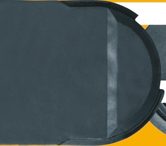
157 7.156

158 hooks. claws. E4/light 7.157

159 System E4/light Narrow outer links Low weight ugged stop dog igumid G -40/+120 C Tongue and groove design Lateral glide surfaces New E4/light version with the special "tongueand-groove-design" from the proven E4/4 Series Low weight Optimized ratio of Interior and exterior dimension Cost-effective Numerous interior separation possibilities Broad system of modular accessories Narrow outer links Max. travel: m You can find more technical data about the material, chemical resistance, temperatures Design, from page 1.38 Opening-principle Dimensioning Bending radius structure Can be opened from both sides Can be opened from both sides and hinged open on one side Ba hi ha Bending radius Color black adius Width Series Selection table Series Inner height Inner width Outer width Outer height Bending radius Unsupported page hi [mm] [mm] Ba [mm] ha [mm] [mm] length max. [m] Crossbars every link - for particulary demanding applications , , , , Crossbars every other link - for almost all applications , , , E-Tube - fully enclosed, excellent cable protection , , ,
160 System E4/light Selection chart Comparison of the main characteristics E4/light hi m m [mm] [mm] [mm] max. [m] max. [kg/m] max. [m/s] [C ] kg C E4/light E-Chain Crossbars every link +120 C E4/light E-Chain Crossbars every 2 nd link E4/light E-Tube Fully enclosed ,5 4,5 4, C 3-40 C Unsupported length FL G = with straight upper run FL B = with permitted sag Inner heights from - to [mm] Inner widths from - to [mm] Bending radii from - to [mm] Unsupported lengths [m] Fill weights [kg/m] Speed max. FL G Speed max. FL B Gliding speed max. Long term temp. min/max. [ C] Additional quality features - System E4/light ESD classification: Electrically conductive ESD/ATEX version upon request System E4/light proved with long travels Side-mounted - unsupported System E4-4-piece design link High torsional rigidity Next Page: Find application examples and assembly instructions 7.159
, and a thinner crossbar (for some types: 142, 143, 1640).")


")
161 System E4/light Applications E4/light - The "light" features appear in two places: A reduced thickness of the side links (for all types), and a thinner crossbar (for some types: 142, 143, 1640). Weight reduction, a large interior space and price reduction result as well as a compromise in strength. E4/light E-Chains achieve optimum price-performance solutions for many industries. Especially for unsupported short travels, hanging and short standing designs. E4/light types are often first choice. Typical industries & applications Machine tools (closed E4/light tubes and open E-Chains ) Material handling Stone cutting machines Woodworking machines General machinery Vehicles Construction machinery Limited long travel applications E4/light - now stronger with the "tongue-and-groove-design" E4/light is popular for hanging applications Circular motions possible (also with "B" - reverse bending radius) E4/light is ideal in Machine Tools with their typical short strokes System E4 E-Chain - carries conduits up to 100 mm diameter 7.160


 -")


162 System E4/light Assembly Instructions E4/light System E4/light E-Chains and E-Tubes Assembling E-Chains Opening Position at one side......and snap in emove crossbars - Insert screwdriver into the slot, push down, release by lever action Position opposite side, press together and snap in 5 Assemble crossbars - Push down and snap in by using a screwdriver 6 emove clips - Insert screwdriver into the slot and push down, release by lever action E-Tubes Opening 1 System E4/light E-Chains and E-Tubes Separating Assemble clips (E-Chains with crossbars Assemble E-Tube lids/bottoms - Attach every other link) - Push down and snap in to the connector at an angle - Snap in emove lids/bottoms - Insert screwdriver into the slot, release by lever action emove crossbars, clips, and lids on two adjacent chain links. Guide the screwdriver into the slot between side links and release it by levering it and separate the E-Chain elease only one side to swivel the lid You can find an assembly video on the web
163 E4/light Price index Series Series Series ESD classification: Electrically conductive ESD/ATEX version upon request High torsional rigidity Side-mounted - unsupported System E4/light Series Crossbars on E-Chains are removable along both radii Hinged snap-open removable lids along outer radius of E- Tube Closed and open styles can be combined Lateral glide surfaces for side-mounted operation Wide, rounded plastic crossbars - cable friendly emovable lids along inner radius Locking or pivoting mounting brackets available KMA mounting brackets with attachment points on all sides Integrated strain relief possible New stronger version with "tongue-and-groove-design" E-Chains also available with reverse bending radius "B" Opening E-Chains : emove crossbars and clips - Insert screwdriver into the slot, push down, release by lever action emove lids/bottoms (E-Tubes) - Insert screwdriver into the slot, release by lever action When to use the Series 14040/14140/18840: For achieving simple, economical solutions For minimizing a chain's external width at any given internal width For use if Series 400 proves too large When not to use it: If a quieter version is required Series 400/410/880, page 7.48 If long side-mounted, unsupported length is required Series 4040/4140/8840, page Order example complete E-Chain Please indicate chain-lenghts or number of links Example: 5 m or 55 links 5 m E-Chain with 2 separators 411 every 2 nd link Interior separation 1 set C Mounting bracket D-CAD files, pdf-downloads
164 E4/light Series Dimensions and Technical Data Unsupported length FL G = with straight upper run FL B = with permitted sag Further information Design, page 1.12 HF H D S/2 S (FL G ) S (FL B ) FL G FL B S Fixed end Moving end FL G FL B Unsupported length FL G / FL B [m] Length of travel S [m] Pitch = 91 mm/link Links/m = 11 (1001 mm) Chain length = S / 2 + K H D K D K H Fill weight [kg/m] H - 84 H H F = H + 50 S = Length of travel = Bending radius H = Nominal clearence height H F = equired clearence height H I = Trough inner height D = Overlength E-Chain radius in final position K = π + "safety" D 2 = Over length - long travels, gliding K 2 = *Further add-on H 2 = *Mounting height *if the mounting bracket location is set lower Other installation methods Vertical, hanging 80 m Vertical, standing 6 m Side mounted, unsupp. 2 m otary requires further calculation Unsupported length of upper run = upon request Short travels - unsupported Unsupported E-Chains feature positive camber over short travels. This must be accounted for when specifying the clearance height H F. Please consult igus if space is particularly restricted. The required clearance height: H F = H + 50 mm (with 2,0 kg/m fill weight) E4/light 56 System E4/light Inner height: 56 mm Long travel lengths from 10 m to max. 150 m Chain length = S / 2 + K 2 S S/2 S/2 Moving end Fixed end H2 D2 K2 Guide trough with glide bar Guide trough without glide bar Total length of guide trough In case of travels between 4 and 10 m we recommend a longer unsupported length. HI Gliding, long travel applications (max. 150 m) In this case the E-Chain upper run will be introduced in a guide trough on the lower run. We recommend to realize the engineering of such a plant by our technicians. Speed / acceleration FL G max. 20 [m/s] / max. 200 [m/s 2 ] Speed / acceleration FL B max. 3 [m/s] / max. 6 [m/s 2 ] Gliding speed / acceleration (maximum) max. 10 [m/s] / max. 50 [m/s 2 ] Material - permitted temperature C igumid G / -40 up to +120 C Flammability class, igumid G VDE 0304 IIC UL94 HB Technical Data C Details of material properties page 1.38 page D-CAD files, pdf-downloads

165 E4/light Ba System E4/light Series Product ange Series E-Chain with crossbars every link igus E-ChainSystems 50 max. structure Color black Bending radius Crossbars every link For rigid hydraulic hoses For applications particularly demanding Can be opened from two sides Width Series 50 max. Ba structure Color black Bending radius Width Series Series E-Chain with crossbars every 2 nd link Crossbars every 2 nd link = Standard For nearly every situation Can be opened from two sides Easy assembly Stable Attractive price Ba Series Fully enclosed E-Tube Fully enclosed igus GmbH Cologne 50 max. structure Color black Bending radius Excellent cable protection against dirt Protection against hot chips (up to 900 C) Lids along the entire inner radius are completely removable. Lids along the entire outer radius are single sided snap-open with a hinge on the other side to keep them attached to the chain or completely removable. Width Series Internet: info@igus.de Series 188 for side-mounted applications; chip-proof tube from the E4 assembly kit on a machine tool here D-CAD files, pdf-downloads
166 System E4/light Series Product ange Part.... No Ba [mm] [mm] [kg/m] [kg/m] [kg/m] 14040/ ,66 2, / ,47 2, /14140/ * ,75 2,25 3, /14140/ ,93 2,61 3, / ,06 2, /14140/ ,12 2,71 3, / ,26 2, /14140/ ,32 2,81 4, / ,43 2, / ,54 2, / ,65 2, /14140/ ,67 2,98 4, / ,78 3, / ,85 3, / ,98 3, /14140/ ,07 3,18 5, / ,16 3, / ,27 3, / ,29 3, /14140/ ,51 3,40 6, / ,57 3, / ,60 3, / ,77 3, /14140/ ,93 3,61 6, / ,94 3, / ,95 3, / ,04 3, /14140/ ,24 3,76 7, / ,39 3, / ,54 3, / ,61 3, / ,68 3, /14140/ ,70 3,99 8, / ,83 4, / ,86 4, / ,96 4, / ,98 4, / ,03 4, / ,18 4, / ,67 4, / ,98 4,58 Available bending radii [mm] 135** Supplement with required radius. Example: = standard color, other colors page 1.39 Pitch = 91 mm/link - Links/m = 11 *emovable lid only, no hinged option **not available for TIP! Hot Chips up to 850 C E-Tubes that repel hot chips, up to 850 ºC Some applications, depending on amount and size of the chips, can burn or melt the surface. That is no longer the case with the new igus "igumid HT" material. Further information: or phone: E4/light System E4/light Inner height: 56 mm Single crossbar, E-Chain, 450. Single lid, E-Tube, 885. ight side link*, single part, E-Chain - links, single parts *View from the fixed point of the E-Chain /E-Tube Left side link*, single part, D-CAD files, pdf-downloads Single bottom, E-Tube, page
167 E4/light E4/light Series Accessories Interior Separation igus E-ChainSystems Option 1 Vertical separators Spacers Locking separators Asymmetric separators E-Chain min.16 E-Tube 411A 415.X min.16 igus GmbH Cologne Internet: info@igus.de Vertical separator 401 Vertical separator 483 Spacer Spacer Spacer Spacer Spacer Locking separator 404 Asymmetric separator 401A Vertical separator /E-Tubes un Vertical separator /E-Tubes un Spacer* un Spacer* un Spacer* un Spacer* un Spacer* un Locking separator un Asymmetric separator* un *For side-mounted applications 401A 411A ,5 18 Option 1: Vertical separators and spacers Vertical separators are used if a vertical subdivision of the E-Chain interior is required - By standard vertical separators are every other E-Chain link. Note: Observe a lateral spacing of at least 16 mm! Standard separator 401 and E-Tubes offers safe stability due to its wide base design, also when used with thick cables or hoses. Vertical separator 483 with a narrow base and E-Tubes with applications where a large number of small cables need to be individually separated. Vertical separators in side-mounted applications, for instance, can be fixed in position by means of spacer 405.X. A wide range of intervals between the vertical separators is adjustable here. Note on spacers: The available interior height is reduced by 2 mm per spacer (4 mm when spacers are fitted on both sides). To avoid this, the parts can also be installed from the outside on the opening crossbar. Additionally: Locking separator with increased retention force for applications exposed to very high humidity or extreme loads. The extra retention force is achieved by asymmetric claws for the crossbar. Ensure proper alignment. Locking separator 406 for E4-Tubes - safe fitting locked on lid or bottom of the Tube and sideways slideable. The opposing lid or bottom can easily be opened and closed. Especially capable if many separators need to be on a tight inner width. Art. Nr. not Art. Nr For illustration, refer to vertical separator 404. Asymmetric separator 401A (not for E- Tubes) with an 18-mm base, for combinations between spacers of different widths and vertical separators in side-mounted applications, for instance D-CAD files, pdf-downloads
168 E4/light Series Accessories Interior Separation E4/light 7 7 Option 2 Option 2: Shelves X Side plate 7 Side plates Middle plates Locking vertical separators Slotted separators Open slotted separators System E4/light Inner height: 56 mm For applications involving many cables with different dia- /E-Tubes Side plate meters. The shelves can be arranged elevator-shifted with un different bottoms. Side plates 402, middle plates 403 and shelves 420.X form the basic pattern of a shelf system. Shelves of various widths can be arranged at 7 different heights (in 7 mm increments). Locking vertical separator 410, slotted combined with shelves. Slotted separators 408 are used for very fine subdivisions. However, they cannot be retrofitted into an existing separation system without dismantling the interior separators first Middle plate /E-Tubes un Locking vertical separator /E-Tubes un Slotted separator Middle plate 403 Locking vertical separator 410 The unilateral open slotted separator 409 can be retro- /E-Tubes Slotted fitted into an existing interior separation system without a need un 408 separator for dismantling the interior separators. During an installation of open slotted separators, the top and bottom notches cannot be occupied by shelves. 3 Open slotted separator /E-Tubes Open slotted un 409 separator Width Width X [mm] un X [mm] un Shelf 420.X X-8 4, Additional elements for interior separation Center crossbar ollclip un 405 un Center crossbar - was developed for applications with a large number of thin cables. sensitive hoses. The ollclip is simply clamped ollclip - minimizes abrasion of particularly The center crossbar offers the option of onto the opening crossbar. The movable rollers subdividing the E-Chain independently into compensate for relative movement between upper and lower halves. the chain and hose. 9 oller separator 18 un oller separator - performs a similar function to the ollclip, but doubles as a separator. page
169 E4/light System E4/light Series Product ange igus E-ChainSystems Extension links - for extremely wide E-Chains up to 3,0 m For applications in which particularly high fill weights necessitate extremely wide E-Chains (up to 3000 mm) The extension link design allows virtually limitless side-by-side attachment of chains The unsupported length of a chain can be increased when additional loads are required Extension links can be used with E-Chains, E-Tubes or as a combination of both They are suitable for unsupported and gliding applications in a guide trough E-Chains with extension links are attached with KMA or steel mounting brackets structure /20 / /2/ ,5 79,5 +1 ø ± 3 ( ) + 18 ± 3 Extender crossbars - careful guide of hosed applications Suitable for hoses with a maximum outer diameter of 300 mm Gliding operation with crossbars along the outer radius and a special guide trough Gliding operation not guaranteed with crossbars along the inner radius The extender crossbar can either be attached to the side links directly or can be used in combination with two stranded snap-open crossbars Consult igus for your extender crossbar applications. ound extender crossbar Attached directly Square extender crossbar Attached directly We are happy to assist you with snap-open crossbars to the side link with snap-open crossbars to the side link with your design layout Max Ø [mm] Form Installation Combination with igus GmbH Cologne hose side link snap-open crossb HD D D D D D HD HD HD = round = square + = yes / = no E4 clip-on cable binder Internet: info@igus.de For side-mounted applications Serves as a clip-on, lateral guide for hoses and cables on E-Chains The loops can be adjusted as required Compatible with many E4 E-Chains Stylish and economical One clip and one locking band are needed for each chain link Call us if you have any questions on project planning Form 450.B B Locking clip, comprising a locking element Locking band, comprising a locking element and band; 12 x 1,5 x 200 mm D-CAD files, pdf-downloads
170 Series Accessories Mounting Brackets, KMA E4/light Moving end The Standard - Option KMA* - pivoting ecommended for unsupported and gliding applications Confined installation conditions Option - integrated C-profile strain relief device with Chainfix clip or strain relief tiewrap plates Corrosion resistant Universal mountable with attachment capability on all sides *KMA = Polymer Metal Mounting Bracket / Fixed end / The attachment variants arising automatically by the choice of the KMA mounting bracket Standard position C-profile Moving end Option KMA - locking ecommended for vertical hanging / standing applications Additionally: Universal mountable C-profile option Corrosion resistant Locked connections At very high acceleration / Fixed end / The attachment variants arising automatically by the choice of the KMA mounting bracket Standard position C-profile Fixed end Moving end / (pivoting) (pivoting) / / (locking) (locking) / Dimensions and order configurations structure (pivoting) C Optional with C-profile Full set Width = E-Chain = E-Tube ø8,5 / t=11, Width full set C-profile Width full set C-profile index pivoting locking option [mm] index pivoting locking option [mm] C C C C / / C / / C / / C C C C / / C C C / / C / / C C C C C C C C / / C / / C C C C C C C / / C C C C C C C C / / C C C 312 structure (locking) C Optional with C-profile Full set, for both ends: Single-part order:bei Width = E-Chain = E-Tube Mounting bracket with bore Mounting bracket with pin 1 2 Full set page D-CAD files, pdf-downloads
171 E4/light igus E-ChainSystems igus Chainfix steel clamps and Chainfix stainless-steel clamps - max. pull forces, adjustable with hexagon socket. Available as single, double or triple clamps. Details chapter 10 E4/light Series Accessories Strain elief Chainfix clamps for the C-profile single clamps double clamps triple clamps Cable steel stainless steel steel stainless steel steel stainless steel ø [mm] CFX12.1 CFX12.1.E CFX12.2 CFX12.2.E CFX CFX14.1 CFX14.1.E CFX14.2 CFX14.2.E CFX CFX16.1 CFX16.1.E CFX16.2 CFX16.2.E CFX CFX18.1 CFX18.1.E CFX18.2 CFX18.2.E CFX CFX20.1 CFX20.1.E CFX20.2 CFX20.2.E CFX CFX22.1 CFX22.1.E CFX22.2 CFX22.2.E CFX CFX26.1 CFX26.1.E CFX26.2 CFX26.2.E CFX30.1 CFX30.1.E CFX30.2 CFX30.2.E CFX34.1 CFX34.1.E CFX34.2 CFX34.2.E CFX38.1 CFX38.1.E CFX42.1 CFX42.1.E Chainfix Clip - Modular snap-on strain relief device for C-profile Available for all igus E-ChainSystems with C- profiles and also suitable for assembly in the KMA mounting brackets and clip-on strain relief for crossbars. High pull forces, plug-in modular snapon strain relief device. Details chapter 10 Chainfix Nugget for the C-Profil Strain relief for the fixation of cables up to a diameter of Ø 20 mm. Easy to assemble, without any screws and tools. Easy strain relief due to fixation with preharnessed cable strap, very small space requirement. Details chapter 10 Cable ø [mm] clamp bottom part CFC-08-M CFC-08-C CFC-12-M CFC-12-C CFC-16-M CFC-16-C CFC-20-M CFC-20-C CFC-24-M CFC-24-C ø max. Width conduit [mm] [mm] CFN ,8 igus GmbH Cologne Chainfix tiewrap plates with clip-on connection for the C-profile Can be plugged into the KMA C-profile. Easy to assemble without any screws. Easily solvable with screwdriver nevertheless safe stop. For all E-Chains with KMA and integrated C-profile. Details chapter 10 Width of Number strain relief [mm] of teeth 3050.ZC ZC 75 7 Internet: info@igus.de Single tiewrap plate Shown Tiewrap plate as individual part As individual component screwed on KMA. Can be plugged in the mounting brackets. Details chapter 10 C B / (n-1) x 10 Tiewrap No. of Dim. C Dim. B Center plate teeth n [mm] [mm] bore 3050.ZB ZB ZB ZB ZB ZB ZB ZB ZB ZB ( = no / + = yes) Details about all strain relief option for this series chapter 10
172 SL SL Trough height: 184 mm Aluminum "SuperTrough" Basic Version Bottom clamp attached optionally inwards or outwards n Mon = n i + 1 M8 x20 B a B i Ba + 4 Ba ha 84 18,4 8 Length of the C-profile according to dimension B i n i x 2000 mm 45 see table 18 11,5 2 H i 2 x ha H a = 184 Components, trough "Basic": Trough side parts, aluminum, 2 m Glide bar, plastic, 2 m Glide strips, plastic, 2 m (without glide strips on request) Optional: Silencer profile, rubber Components, installation set "Basic": Bottom clamp, aluminum C-profile, steel galvanized Screw M8 x20 Sliding nut M8 Interface connector, plastic Order example: Length of travel 30 m - Center mounted for Series with B i = 130 Guide trough set (set of 2 trough side parts, incl. glide strips) without glide bar Order text: 16 m guide trough without glide bar (8 x 2 m sections) Guide trough set (set of 2 trough side parts, incl. glide strips) with glide bar Order text: 16 m guide trough with glide bar (8 x 2 m sections) Installation set "Basic" complete (guide trough-sets + 1) Order text: 17 installation sets "Basic" Module for the fixed end Order text: 1 set Option: For an additional noise dampening with silencer profile, please add Index A - Example: SL SL SLA Principle sketch: Number of installation sets to be installed = Number of trough sections + 1 NEW! A quick fix for mounting the stationary end of an E-Chain With this new module for the fixed end, fast and easy mounting onto the Aluminum "SuperTrough" is now possible without any drilling. Fast mounting of the E-Chain by clamping onto the aluminum trough Quick relocation of the stationary end No drilling necessary page 9.16 Details about Alu "SuperTrough" and further guidance possibilities Ba ha = Outer width E-Chains / E-Tube = Inner width E-Chains / E-Tube = Outer height E-Chains / E-Tube [mm] inwards outwards Insert for the installation set "Heavy-Duty": XXX instead of ( XXX) on the right column "attached outwards" chapter 9, Guide Troughs E4/light H i = Inner trough height H a = Outer trough height B i = Inner trough width depends on dim. Ba B a = Outer trough width n Mon = Number of installation sets (left/right) n i = Number of troughs sets (left/right) H! i 2 ha B i Ba + 4 = Guide trough set = Glide bar = Installation set "Basic" = C-profile Installation set "Basic" with C-profile Bottom Clamp attached optionally inwards or outwards Order example B i attached attached Chapter 10 Chapter 9 page


173 E4/light System E4/light Series Price index Series Series ESD classification: Electrically conductive ESD/ATEX version upon request High torsional rigidity Side-mounted - unsupported Crossbars on E-Chains are removable along both radii Wide, rounded plastic crossbars - cable friendly Optimum ratio of inner height to outer height Lateral glide surfaces for side-mounted operation Integrated strain relief possible Locking or pivoting mounting brackets available KMA mounting brackets with attachment points on all sides New stronger version with "tongue-and-groove-design" Numerous interior separation possibilities E-Chains also available with reverse bending radius "B" Opening E-Chains : emove crossbars and clips - Insert screwdriver into the slot, push down, release by lever action When to use the Series 14240/14340: For achieving simple, economical solutions For achieving the ideal ratio between internal and external dimensions For use if Series 400 proves too large When not to use it: If a quieter version is required Series 400/410/880, page 7.48 If long side-mounted, unsupported length is required Series 4040/4140/8840, page If an increased inner height is required Series 15050, page Order example complete E-Chain Please indicate chain-lenghts or number of links Example: 6 m or 66 links 6 m E-Chain with 2 separators 417 every 2 nd link Interior separation 1 set C Mounting bracket D-CAD files, pdf-downloads and many online features
174 E4/light Series Dimensions and Technical Data E4/light Unsupported length FL G = with straight upper run FL B = with permitted sag Further information Design, page 1.12 HF H D S/2 S (FL G ) S (FL B ) FL G FL B S Fixed end Moving end FL G FL B Unsupported length FL G / FL B [m] Length of travel S [m] Pitch = 91 mm/link Links/m = 11 (1001 mm) Chain length = S / 2 + K H D K D K H Fill weight [kg/m] H - 84 H H F = H + 50 S = Length of travel = Bending radius H = Nominal clearence height H F = equired clearence height H I = Trough inner height D = Overlength E-Chain radius in final position K = π + "safety" D 2 = Over length - long travels, gliding K 2 = *Further add-on H 2 = *Mounting height *if the mounting bracket location is set lower Other installation methods Vertical, hanging 80 m Vertical, standing 6 m Side mounted, unsupp. 2 m otary requires further calculation Unsupported length of upper run = upon request Short travels - unsupported Unsupported E-Chains feature positive camber over short travels. This must be accounted for when specifying the clearance height H F. Please consult igus if space is particularly restricted. The required clearance height: H F = H + 50 mm (with 2,0 kg/m fill weight) 62 System E4/light Inner height: 62 mm Long travel lengths from 10 m to max. 150 m Chain length = S / 2 + K 2 S S/2 S/2 Moving end Fixed end H2 D2 K2 Guide trough with glide bar Guide trough without glide bar Total length of guide trough In case of travels between 4 and 10 m we recommend a longer unsupported length. HI Gliding, long travel applications (max. 150 m) In this case the E-Chain upper run will be introduced in a guide trough on the lower run. We recommend to realize the engineering of such a plant by our technicians. Speed / acceleration FL G max. 20 [m/s] / max. 200 [m/s 2 ] Speed / acceleration FL B max. 3 [m/s] / max. 6 [m/s 2 ] Gliding speed / acceleration (maximum) max. 10 [m/s] / max. 50 [m/s 2 ] Material - permitted temperature C igumid G / -40 up to +120 C Flammability class, igumid G VDE 0304 IIC UL94 HB Technical Data C Details of material properties page 1.38 page D-CAD files, pdf-downloads and many online features

175 E4/light System E4/light Series Product ange Ba Series E-Chain with crossbars every link igus E-ChainSystems 56 max. structure Color black Bending radius Crossbars every link For rigid hydraulic hoses For applications particularly demanding Can be opened from two sides 56 max. Ba igus GmbH Cologne Width Series structure Color black Bending radius Width Series Series E-Chain with crossbars every 2 nd link Crossbars every 2 nd link = Standard For nearly every situation Can be opened from two sides Easy assembly Stable Attractive price Internet: info@igus.de Vertical, standing installation on a machine tool with Series D-CAD files, pdf-downloads and many online features
176 System E4/light Series Product ange E4/light Part.... No Ba [mm] [mm] [kg/m] [kg/m] 14240/ ,37 2, / ,40 2, / ,42 2, / ,47 2, / ,52 2, / ,55 2, / ,55 2, / ,62 2, / ,66 2, / ,72 2, / ,73 2, / ,79 2, / ,82 2, / ,84 2, / ,89 2, / ,95 2, / ,01 2, / ,04 2, / ,10 2, / ,11 2, / ,19 2, / ,20 2, / ,30 2, / ,31 2, / ,37 2, / ,40 2, / ,56 2, / ,61 2, / ,64 2, / ,69 2, / ,73 2,99 Available bending radii [mm] Supplement with required radius. Example: = standard color, other colors page 1.39 Pitch = 91 mm/link - Links/m = 11 Extender crossbar for large diameter hoses page System E4/light Inner height: 62 mm Single crossbar, E-Chain, 385. ight side link*, single part, E-Chain - links, single parts *View from the fixed point Left side link*, single part, Single crossbar, E-Chain, 385. page D-CAD files, pdf-downloads and many online features
177 E4/light E4/light Series Accessories Interior Separation igus E-ChainSystems Option 1 Vertical separators Spacers 382.X X Vertical separator 407 Spacer Spacer Spacer , Internet: info@igus.de igus GmbH Cologne Vertical separator un Spacer* un Spacer* un Spacer* un Option 1: Vertical separators and spacers Vertical separators are used if a vertical subdivision of the E-Chain interior is required - By standard vertical separators are every other E-Chain link. Standard separator 407 offers safe stability due to its wide base design, also when used with thick cables or hoses. Vertical separators in side-mounted applications, for instance, can be fixed in position by means of spacer 381.X. A wide range of intervals between the vertical separators is adjustable here. Note on spacers: The available interior height is reduced by 2 mm per spacer (4 mm when spacers are fitted on both sides). To avoid this, the parts can also be installed from the outside on the opening crossbar. *For side-mounted applications D-CAD files, pdf-downloads and many online features
178 E4/light Series Accessories Interior Separation E4/light 7 7 Option 2 Option 2: Shelves X For applications involving many cables with different diameters. The shelves can be arranged elevator-shifted with different bottoms. Side plates 146, middle plates 148 and shelves 386.X form the basic pattern of a shelf system. Shelves of various widths can be arranged at 7 different heights (in 7 mm increments). Slotted separators 1407 are used for very fine subdivisions. However, they cannot be retrofitted into an existing separation system without dismantling the interior separators first Side plate un Middle plate un Slotted separator un Side plates Middle plates Slotted separators Side plate 146 Middle plate 148 Slotted separator 1407 System E4/light Inner height: 62 mm Width X [mm] un Width X [mm] un Shelf 386.X Shelf X-8 4 page D-CAD files, pdf-downloads and many online features
179 E4/light System E4/light Series Product ange igus E-ChainSystems Ba Ba igus GmbH Cologne ,5 mm Ba Ba Internet: Consult igus for your extender crossbar applications. We are happy to assist you with your design layout Extender crossbars - careful guide of hosed applications Suitable for hoses with a maximum outer diameter of 115 mm Gliding operation with crossbars along the outer radius and a special guide trough Gliding operation not guaranteed with crossbars along the inner radius The extender crossbar can either be attached to the side links directly or can be used in combination with two stranded snap-open crossbars HD115 round extender crossbar D115 round strap combined with snap-open crossbars attached directly on the side link Max Ø [mm] Form Installation Combination with hose side link snap-open crossb HD D = round + = yes / = no Hinged crossbars Typically E-Chain crossbars are completely removable. In cases where the snap-open crossbars have to remain at the open link of the E-Chain, a hinged design has been developed Length: 37,5 mm / snap-open crossbar (shortened): -37,5 mm Please consult igus for design assistance Option 1 Option 2 Option 3 Option D-CAD files, pdf-downloads and many online features
180 E4/light Series Accessories Mounting Brackets, KMA E4/light Moving end The Standard - Option KMA* - pivoting ecommended for unsupported and gliding applications Confined installation conditions Option - integrated C-profile strain relief device with Chainfix clip or strain relief tiewrap plates Corrosion resistant Universal mountable with attachment capability on all sides *KMA = Polymer Metal Mounting Bracket Fixed end The attachment variants arising automatically by the choice of the KMA mounting bracket Standard position C-profile Moving end Option KMA - locking ecommended for vertical hanging / standing applications Additionally: Universal mountable C-profile option Corrosion resistant Locked connections At very high acceleration Fixed end The attachment variants arising automatically by the choice of the KMA mounting bracket Standard position C-profile Fixed end Moving end (pivoting) (pivoting) (locking) (locking) Dimensions and order configurations structure (pivoting) C Optional with C-profile Full set Width E-Chain structure (locking) ø8,5 / t=11, Width full set C-profile index pivoting locking option [mm] C C C C C C C C C C C C C C C C 212 Width full set C-profile index pivoting locking option [mm] C C C C C C C C C C C C C C C C Full set, for both ends: Single-part order:bei Optional with C-profile E-Chain Mounting bracket with pin Mounting bracket with bore 1 2 Full set Width page D-CAD files, pdf-downloads and many online features
181 E4/light E4/light Series Accessories Strain elief igus E-ChainSystems igus Chainfix steel clamps and Chainfix stainless-steel clamps - max. pull forces, adjustable with hexagon socket. Available as single, double or triple clamps. Details chapter 10 Chainfix clamps for the C-profile single clamps double clamps triple clamps Cable steel stainless steel steel stainless steel steel stainless steel ø [mm] CFX12.1 CFX12.1.E CFX12.2 CFX12.2.E CFX CFX14.1 CFX14.1.E CFX14.2 CFX14.2.E CFX CFX16.1 CFX16.1.E CFX16.2 CFX16.2.E CFX CFX18.1 CFX18.1.E CFX18.2 CFX18.2.E CFX CFX20.1 CFX20.1.E CFX20.2 CFX20.2.E CFX CFX22.1 CFX22.1.E CFX22.2 CFX22.2.E CFX CFX26.1 CFX26.1.E CFX26.2 CFX26.2.E CFX30.1 CFX30.1.E CFX30.2 CFX30.2.E CFX34.1 CFX34.1.E CFX34.2 CFX34.2.E CFX38.1 CFX38.1.E CFX42.1 CFX42.1.E Chainfix Clip - Modular snap-on strain relief device for C-profile Available for all igus E-ChainSystems with C- profiles and also suitable for assembly in the KMA mounting brackets and clip-on strain relief for crossbars. High pull forces, plug-in modular snapon strain relief device. Details chapter 10 Chainfix Nugget for the C-Profil Strain relief for the fixation of cables up to a diameter of Ø 20 mm. Easy to assemble, without any screws and tools. Easy strain relief due to fixation with preharnessed cable strap, very small space requirement. Details chapter 10 Cable ø [mm] clamp bottom part CFC-08-M CFC-08-C CFC-12-M CFC-12-C CFC-16-M CFC-16-C CFC-20-M CFC-20-C CFC-24-M CFC-24-C ø max. Width conduit [mm] [mm] CFN ,8 igus GmbH Cologne Chainfix tiewrap plates with clip-on connection for the C-profile Can be plugged into the KMA C-profile. Easy to assemble without any screws. Easily solvable with screwdriver nevertheless safe stop. For all E-Chains with KMA and integrated C-profile. Details chapter 10 Width of Number strain relief [mm] of teeth 3050.ZC ZC 75 7 Internet: info@igus.de Single tiewrap plate Shown Tiewrap plate as individual part As individual component screwed on KMA. Can be plugged in the mounting brackets. Details chapter 10 C B / (n-1) x 10 Tiewrap No. of Dim. C Dim. B Center plate teeth n [mm] [mm] bore 3050.ZB ZB ZB ZB ZB ZB ZB ZB ZB ZB ( = no / + = yes) Details about all strain relief option for this series chapter 10
182 SL SL Trough height: 184 mm Aluminum "SuperTrough" Basic Version E4/light Bottom clamp attached optionally inwards or outwards n Mon = n i + 1 M8 x20 B a B i Ba + 4 Ba ha 84 18,4 8 Length of the C-profile according to dimension B i n i x 2000 mm 45 see table 18 11,5 2 H i 2 x ha H a = 184 Components, trough "Basic": Trough side parts, aluminum, 2 m Glide bar, plastic, 2 m Glide strips, plastic, 2 m (without glide strips on request) Optional: Silencer profile, rubber Components, installation set "Basic": Bottom clamp, aluminum C-profile, steel galvanized Screw M8 x20 Sliding nut M8 Interface connector, plastic Order example: Length of travel 30 m - Center mounted for Series with B i = 130 Guide trough set (set of 2 trough side parts, incl. glide strips) without glide bar Order text: 16 m guide trough without glide bar (8 x 2 m sections) Guide trough set (set of 2 trough side parts, incl. glide strips) with glide bar Order text: 16 m guide trough with glide bar (8 x 2 m sections) Installation set "Basic" complete (guide trough-sets + 1) Order text: 17 installation sets "Basic" Module for the fixed end Order text: 1 set Option: For an additional noise dampening with silencer profile, please add Index A - Example: SL SL SLA Principle sketch: Number of installation sets to be installed = Number of trough sections + 1 NEW! A quick fix for mounting the stationary end of an E-Chain With this new module for the fixed end, fast and easy mounting onto the Aluminum "SuperTrough" is now possible without any drilling. Fast mounting of the E-Chain by clamping onto the aluminum trough Quick relocation of the stationary end No drilling necessary page 9.16 Details about Alu "SuperTrough" and further guidance possibilities Ba ha = Outer width E-Chains / E-Tube = Inner width E-Chains / E-Tube = Outer height E-Chains / E-Tube H i = Inner trough height H a = Outer trough height B i = Inner trough width depends on dim. Ba B a = Outer trough width n Mon = Number of installation sets (left/right) n i = Number of troughs sets (left/right) H! i 2 ha B i Ba + 4 = Guide trough set = Glide bar = Installation set "Basic" = C-profile Installation set "Basic" with C-profile Bottom Clamp attached optionally inwards or outwards Order example B i attached attached [mm] inwards outwards Insert for the installation set "Heavy-Duty": XXX instead of ( XXX) on the right column "attached outwards" chapter 9, Guide Troughs Chapter 10 Chapter 9 page
183 E4/light System E4/light Series Price index Series Series Series ESD classification: Electrically conductive ESD/ATEX version upon request High torsional rigidity Side-mounted - unsupported New stronger version with "tongue-and-groove-design" High torsional rigity Crossbars are removable along both radii Hinged snap-open removable lids along outer radius Closed and open styles can be combined Lateral glide surfaces for side-mounted operation Numerous interior separation possibilities Wide, rounded plastic crossbars - cable friendly KMA mounting brackets with attachment points on all sides Integrated strain relief possible Opening E-Chains : emove crossbars and clips - Insert screwdriver into the slot, push down, release by lever action emove lids/bottoms (E-Tubes) - Insert screwdriver into the slot, release by lever action When to use the Series 15050/15150/19850: For achieving simple, economical solutions For minimizing a chain's external width at any given internal width For use if Series 5050 proves too large When not to use it: If long side-mounted, unsupported length is required E4/4, Series 5050/5150/9850, page Order example complete E-Chain Please indicate chain-lenghts or number of links Example: 5 m or 55 links 5 m E-Chain with 2 separators 511 every 2 nd link Interior separation 1 set C Mounting bracket D-CAD files, pdf-downloads
184 E4/light Series Dimensions and Technical Data Unsupported length FL G = with straight upper run FL B = with permitted sag Further information Design, page 1.12 HF H D S/2 S (FL G ) S (FL B ) FL G FL B S Fixed end Moving end FL G FL B Unsupported length FL G / FL B [m] Length of travel S [m] Pitch = 91 mm/link Links/m = 11 (1001 mm) Chain length = S / 2 + K H D K D K H Fill weight [kg/m] H H H F = H + 60 S = Length of travel = Bending radius H = Nominal clearence height H F = equired clearence height H I = Trough inner height D = Overlength E-Chain radius in final position K = π + "safety" D 2 = Over length - long travels, gliding K 2 = *Further add-on H 2 = *Mounting height *if the mounting bracket location is set lower Other installation methods Vertical, hanging 100 m Vertical, standing 6 m Side mounted, unsupp. 2 m otary requires further calculation Unsupported length of upper run = upon request Short travels - unsupported Unsupported E-Chains feature positive camber over short travels. This must be accounted for when specifying the clearance height H F. Please consult igus if space is particularly restricted. The required clearance height: H F = H + 60 mm (with 3,0 kg/m fill weight) E4/light 80 System E4/light Inner height: 80 mm Long travel lengths from 10 m to max. 250 m Chain length = S / 2 + K 2 S S/2 S/2 Moving end Fixed end H2 D2 K2 Guide trough with glide bar Guide trough without glide bar Total length of guide trough In case of travels between 4 and 10 m we recommend a longer unsupported length. HI Gliding, long travel applications (max. 250 m) In this case the E-Chain upper run will be introduced in a guide trough on the lower run. We recommend to realize the engineering of such a plant by our technicians. Speed / acceleration FL G max. 20 [m/s] / max. 200 [m/s 2 ] Speed / acceleration FL B max. 3 [m/s] / max. 6 [m/s 2 ] Gliding speed / acceleration (maximum) max. 10 [m/s] / max. 50 [m/s 2 ] Material - permitted temperature C igumid G / -40 up to +120 C Flammability class, igumid G VDE 0304 IIC UL94 HB Technical Data C Details of material properties page 1.38 page D-CAD files, pdf-downloads
185 E4/light Ba System E4/light Series Product ange Series E-Chain with crossbars every link igus E-ChainSystems 74 max. structure Color black Bending radius Crossbars every link For rigid hydraulic hoses For applications particularly demanding Can be opened from two sides 74 max. Ba Ba igus GmbH Cologne 74 max. structure Color black Bending radius Width Series Internet: info@igus.de Width Series structure Color black Bending radius Width Series Series E-Chain with crossbars every 2 nd link Crossbars every 2 nd link = Standard For nearly every situation Can be opened from two sides Easy assembly Stable Attractive price Series Fully enclosed E-Tube Fully enclosed Excellent cable protection against dirt Protection against hot chips (up to 900 C) Lids along the entire inner radius are completely removable. Lids along the entire outer radius are single sided snap-open with a hinge on the other side to keep them attached to the chain or completely removable D-CAD files, pdf-downloads
186 System E4/light Series Product ange Part.... No Ba [mm] [mm] [kg/m] [kg/m] [kg/m] 15050/ ,85 3, /15150/ * ,00 3,92 4, /15150/ ,18 4,00 4, / ,31 4, /15150/ ,38 4,10 5, / ,51 4, /15150/ ,58 4,20 5, / ,69 4, / ,80 4, / ,91 4, /15150/ ,93 4,38 6, / ,04 4, / ,10 4, / ,24 4, /15150/ ,32 4,58 6, / ,41 4, /15150/ ,52 4,68 7, / ,54 4, /15150/ ,76 4,80 7, / ,80 4, / ,85 4, / ,03 4, /15150/ ,18 5,01 8, / ,19 5, / ,20 5, / ,29 5, /15150/ ,49 5,16 9, / ,64 5, / ,80 5, / ,86 5, / ,93 5, /15150/ ,95 5,39 9, / ,08 5, / ,16 5, / ,22 5, / ,24 5, / ,28 5, / ,44 5, / ,92 5, / ,12 5,97 Available bending radii [mm] 150** Supplement with required radius. Example: = standard color, other colors page 1.39 Pitch = 91 mm/link - Links/m = 11 *not available for TIP! Hot Chips up to 850 C E-Tubes that repel hot chips, up to 850 ºC Some applications, depending on amount and size of the chips, can burn or melt the surface. That is no longer the case with the new igus "igumid HT" material. Further information: or phone: Extender crossbar for large diameter hoses page E4/light System E4/light Inner height: 80 mm Single crossbar, E-Chain, 450. Single lid, E-Tube, 885. ight side link*, single part, E-Chain - links, single parts *View from the fixed point of the E-Chain /E-Tube Left side link*, single part, Single bottom, E-Tube, 886. page D-CAD files, pdf-downloads
187 E4/light E4/light Series Accessories Interior Separation igus E-ChainSystems Option 1 Vertical separators Spacers Locking separators Asymmetric separators min.16 E-Chain E-Tube 511A X min.16 Vertical separator 501 Spacer Spacer Spacer Vertical separator /E-Tubes un Spacer* un Spacer* un Spacer* un Option 1: Vertical separators and spacers Vertical separators are used if a vertical subdivision of the E-Chain interior is required - By standard vertical separators are every other E-Chain link. Note: Observe a lateral spacing of at least 16 mm! Standard separator 501 and E-Tubes offers safe stability due to its wide base design, also when used with thick cables or hoses. Vertical separators in side-mounted applications, for instance, can be fixed in position by means of spacer 405.X. A wide range of intervals between the vertical separators is adjustable here. Note on spacers: The available interior height is reduced by 2 mm per spacer (4 mm when spacers are fitted on both sides). To avoid this, the parts can also be installed from the outside on the opening crossbar. Spacer* Spacer igus GmbH Cologne Internet: info@igus.de Spacer Locking separator 504 Locking separator 508 Asymmetric separator 501A un Spacer* un Locking separator un Locking separator un Asymmetric separator* un *For side-mounted applications 501A 511A ,5 3,5 18 Additionally: Locking separator 504- with increased retention force for applications exposed to very high humidity or extreme loads. If locking separators are used, the E-Chain is more difficult to open. The Locking separator 508 is designed for applications exposed to extremely high humidity, for example, at composting plants. The lateral cam serves for uniform alignment of the vertical separators; if these separators are misaligned, they will inevitably get damaged on an attempt to open the E-Chain. Asymmetric separator 501A (not for E- Tubes) with an 18-mm base, for combinations between spacers of different widths and vertical separators in side-mounted applications, for instance D-CAD files, pdf-downloads
188 E4/light Series Accessories Interior Separation E4/light 7 Option 2: Shelves X For applications involving many cables with different diameters. The shelves can be arranged elevator-shifted with different bottoms. Side plates 502, middle plates 503 and shelves 420.X form the basic pattern of a shelf system. Shelves of various widths can be arranged at 11 different heights (in 7 mm increments). Locking vertical separator 510 combined with shelves. Triple slots. Locking separator 507 slotted - with increased retention force for applications exposed to very high humidity or extreme loads. The extra retention force is achieved by asymmetric claws for the crossbar. Ensure proper alignment. Slotted separators 505 are used for very fine subdivisions. However, they cannot be retrofitted into an existing separation system without dismantling the interior separators first. The unilateral open slotted separator 509 can be retrofitted into an existing interior separation system without a need for dismantling the interior separators. During an installation of open slotted separators, the top and bottom notches cannot be occupied by shelves , Side plate /E-Tubes un Middle plate /E-Tubes un Locking vertical separator /E-Tubes un Locking separator un Slotted separator /E-Tubes un Open slotted separator /E-Tubes un Option 2 Side plates Middle plates Locking vertical separators Locking separators Slotted separators Open slotted separators Side plate 502 Middle plate 503 Locking vertical separator 510 Locking separator 507 Slotted separator 505 Open slotted separator 509 System E4/light Inner height: 80 mm Width X [mm] un Width X [mm] un Shelf 420.X X-8 4,5 Additional elements for interior separation ollclip - minimizes abrasion of particularly ollclip sensitive hoses. The ollclip is simply clamped 9 un onto the opening crossbar. The movable rollers compensate for relative movement between the chain and hose. 27 mm page
189 E4/light igus E-ChainSystems System E4/light Series Product ange Extension links - for extremely wide E-Chains up to 3,0 m For applications in which particularly high fill weights necessitate extremely wide E-Chains (up to 3000 mm) The extension link design allows virtually limitless side-by-side attachment of chains The unsupported length of a chain can be increased when additional loads are required Extension links can be used with E-Chains, E-Tubes or as a combination of both They are suitable for unsupported and gliding applications in a guide trough E-Chains with extension links are attached with KMA or steel mounting brackets structure /20 / /2/ ,5 79,5 +1 ø ± 3 ( ) + 22 ± 3 Extender crossbars - careful guide of hosed applications Suitable for hoses with a maximum outer diameter of 300 mm Gliding operation with crossbars along the outer radius and a special guide trough Gliding operation not guaranteed with crossbars along the inner radius The extender crossbar can either be attached to the side links directly or can be used in combination with two stranded snap-open crossbars igus GmbH Cologne Consult igus for your extender crossbar applications. We are happy to assist you with your design layout ound extender crossbar Attached directly Square extender crossbar Attached directly with snap-open crossbars to the side link with snap-open crossbars to the side link Max Ø [mm] Form Installation Combination with hose side link snap-open crossb HD D D D D D HD HD HD = round = square + = yes / = no Internet: info@igus.de E4 clip-on cable binder For side-mounted applications Serves as a clip-on, lateral guide for hoses and cables on E-Chains The loops can be adjusted as required Compatible with many E4 E-Chains Stylish and economical One clip and one locking band are needed for each chain link Call us if you have any questions on project planning Form 450.B B Locking clip, comprising a locking element Locking band, comprising a locking element and band; 12 x 1,5 x 200 mm D-CAD files, pdf-downloads
190 Series Accessories Mounting Brackets, KMA E4/light Moving end The Standard - Option KMA* - pivoting ecommended for unsupported and gliding applications Confined installation conditions Option - integrated C-profile strain relief device with Chainfix clip or strain relief tiewrap plates Corrosion resistant Universal mountable with attachment capability on all sides *KMA = Polymer Metal Mounting Bracket / Fixed end / The attachment variants arising automatically by the choice of the KMA mounting bracket Standard position C-profile Moving end Option KMA - locking ecommended for vertical hanging / standing applications Additionally: Universal mountable C-profile option Corrosion resistant Locked connections At very high acceleration / Fixed end / The attachment variants arising automatically by the choice of the KMA mounting bracket Standard position C-profile Fixed end Moving end / (pivoting) (pivoting) / / (locking) (locking) / Dimensions and order configurations structure (pivoting) C Optional with C-profile Full set Width = E-Chain = E-Tube ø9 / t=11, Width full set C-profile index pivoting locking option [mm] index pivoting locking option [mm] C C / / C C 312 Width full set C-profile C / / C / / C C C / / C C C C / / C / / C C C C C C C / / C C C / / C C C C C / / C C C C / / C C C C / / C C C 600 structure (locking) C Optional with C-profile Full set, for both ends: Single-part order: Mounting bracket with pin Width = E-Chain = E-Tube Mounting bracket with bore 1 2 Full set page D-CAD files, pdf-downloads
191 E4/light Series Accessories Mounting Brackets, Steel Moving end Option steel - pivoting For pivoting connections One part (two-piece) for all chain widths Electrically conductive Possible installation conditions - Further installation angles installation sketch Fixed end Moving end Fixed end igus GmbH Cologne Internet: info@igus.de Full set, 4 parts 2 with pin / 2 with bore Single-part order: Mounting bracket with bore, 1 part left / right Mounting bracket with pin, 1 part left / right Other strain relief elements chapter 10 For E-Chain full set [mm] For E-Chain full set [mm] D-CAD files, pdf-downloads
192 2 8 6 E4/light Series Accessories Strain elief Chainfix clamps for the C-profile single clamps double clamps triple clamps Cable steel stainless steel steel stainless steel steel stainless steel ø [mm] CFX12.1 CFX12.1.E CFX12.2 CFX12.2.E CFX CFX14.1 CFX14.1.E CFX14.2 CFX14.2.E CFX CFX16.1 CFX16.1.E CFX16.2 CFX16.2.E CFX CFX18.1 CFX18.1.E CFX18.2 CFX18.2.E CFX CFX20.1 CFX20.1.E CFX20.2 CFX20.2.E CFX CFX22.1 CFX22.1.E CFX22.2 CFX22.2.E CFX CFX26.1 CFX26.1.E CFX26.2 CFX26.2.E CFX30.1 CFX30.1.E CFX30.2 CFX30.2.E CFX34.1 CFX34.1.E CFX34.2 CFX34.2.E CFX38.1 CFX38.1.E CFX42.1 CFX42.1.E igus Chainfix steel clamps and Chainfix stainless-steel clamps - max. pull forces, adjustable with hexagon socket. Available as single, double or triple clamps. Details chapter E4/light System E4/light Inner height: 80 mm Cable ø [mm] clamp bottom part CFC-08-M CFC-08-C CFC-12-M CFC-12-C CFC-16-M CFC-16-C CFC-20-M CFC-20-C CFC-24-M CFC-24-C ø max. Width conduit [mm] [mm] CFN ,8 Chainfix Clip - Modular snap-on strain relief device for C-profile Available for all igus E-ChainSystems with C- profiles and also suitable for assembly in the KMA mounting brackets and clip-on strain relief for crossbars. High pull forces, plug-in modular snapon strain relief device. Details chapter 10 Chainfix Nugget for the C-Profil Strain relief for the fixation of cables up to a diameter of Ø 20 mm. Easy to assemble, without any screws and tools. Easy strain relief due to fixation with preharnessed cable strap, very small space requirement. Details chapter 10 Width of Number strain relief [mm] of teeth 3050.ZC ZC 75 7 Chainfix tiewrap plates with clip-on connection for the C-profile Can be plugged into the KMA C-profile. Easy to assemble without any screws. Easily solvable with screwdriver nevertheless safe stop. For all E-Chains with KMA and integrated C-profile. Details chapter 10 Tiewrap No. of Dim. C Dim. B Center plate teeth n [mm] [mm] bore 3050.ZB ZB ZB ZB ZB ZB ZB ZB ZB ZB ( = no / + = yes) 6.2 Tiewrap plate as individual part As individual component screwed on KMA. Can be plugged in the mounting brackets. Details chapter 10 C B 2 8 (n-1) x 10 Details about all strain relief option for this series chapter 10 12/ Single tiewrap plate Shown Chapter 10 page
193 E4/light SL SL Trough height: 236 mm Aluminum "SuperTrough" Basic Version B a Ba = Outer width E-Chains / E-Tube = Inner width E-Chains / E-Tube ha = Outer height E-Chains / E-Tube H i = Inner trough height H a = Outer trough height B i = Inner trough width depends on dim. Ba B a = Outer trough width n Mon = Number of installation sets (left/right) n i = Number of troughs sets (left/right)! H i 2 ha B i Ba + 4 = Guide trough set = Glide bar = Installation set "Basic" = C-profile B i Ba + 4 Ba ha 11,5 2 H i 2 x ha H a = 236 igus GmbH Cologne Internet: info@igus.de Installation set "Basic" with C-profile Bottom Clamp attached optionally inwards or outwards Order example B i attached attached [mm] inwards outwards Insert for the installation set "Heavy-Duty": XXX instead of ( XXX) on the right column "attached outwards" Bottom clamp attached optionally inwards or outwards n Mon = n i + 1 M8 x20 Details about Alu "SuperTrough" and further guidance possibilities ,4 8 Length of the C-profile according to dimension B i n i x 2000 mm 51,5 18 see table Components, trough "Basic": Trough side parts, aluminum, 2 m Glide bar, plastic, 2 m Glide strips, plastic, 2 m (without glide strips on request) Optional: Silencer profile, rubber Components, installation set "Basic": Bottom clamp, aluminum C-profile, steel galvanized Screw M8 x20 Sliding nut M8 Interface connector, plastic Order example: Length of travel 30 m - Center mounted for Series with B i = 334 Guide trough set (set of 2 trough side parts, incl. glide strips) without glide bar Order text: 16 m guide trough without glide bar (8 x 2 m sections) Guide trough set (set of 2 trough side parts, incl. glide strips) with glide bar Order text: 16 m guide trough with glide bar (8 x 2 m sections) Installation set "Basic" complete (guide trough-sets + 1) Order text: 17 installation sets "Basic" Module for the fixed end Order text: 1 set Option: For an additional noise dampening with silencer profile, please add Index A - Example: SL SL SLA Principle sketch: Number of installation sets to be installed = Number of trough sections + 1 NEW! A quick fix for mounting the stationary end of an E-Chain With this new module for the fixed end, fast and easy mounting onto the Aluminum "SuperTrough" is now possible without any drilling. Fast mounting of the E-Chain by clamping onto the aluminum trough Quick relocation of the stationary end No drilling necessary page 9.16 chapter 9, Guide Troughs
194 My Sketches E4/light System E4/light Inner height: 80 mm TPE Bus cables for maximum load requirement - Chainflex CFBUS TPE outer jacket, shielded, oil-resistant, bio-oil-resistant, flame-retardant Further information: chainflex CFBUS TIP! Chapter 9 page D-CAD files, pdf-downloads
195 E4/light Increased inner height System E4/light Series Price index Series 1640 Series 1608 ESD classification: Electrically conductive ESD/ATEX version upon request High torsional rigidity Numerous interior separation possibilities Wide, rounded plastic crossbars - cable friendly Lateral glide surfaces for side-mounted operation Closed and open styles can be combined Hinged snap-open removable lids along outer radius emovable lids along inner radius Dirt-repellent exterior E-Chains also available with reverse bending radius "B" Side-mounted - unsupported Opening E-Chains : emove crossbars and clips - Insert screwdriver into the slot, push down, release by lever action emove lids/bottoms (E-Tubes) - Insert screwdriver into the slot, release by lever action When to use the Series 1640/1608: For achieving simple, economical solutions For minimizing a chain's external width at any given internal width For use if Series 640 proves too large Order example complete E-Chain Please indicate chain-lenghts or number of links Example: 2 m or 14 links When not to use it: If maximum stability is required Series 600/608, page m E-Chain with 2 separators 6411 every 2 nd link Interior separation 1 set Mounting bracket D-CAD files, pdf-downloads and many online features
196 System E4/light Series Dimensions and Technical Data E4/light Unsupported length FL G = with straight upper run FL B = with permitted sag Further information Design, page 1.12 HF H D S (FL G ) S (FL B ) FL G FL B S S/2 Fixed end Moving end FL G FL B Unsupported length FL G / FL B [m] Length of travel S [m] Pitch = 143 mm/link Links/m = 7 (1001 mm) Chain length = S / 2 + K H D K D K H Fill weight [kg/m] H H H F = H S = Length of travel = Bending radius H = Nominal clearence height H F = equired clearence height H I = Trough inner height D = Overlength E-Chain radius in final position K = π + "safety" D 2 = Over length - long travels, gliding K 2 = *Further add-on H 2 = *Mounting height *if the mounting bracket location is set lower Other installation methods Vertical, hanging 100 m Vertical, standing 5 m Side mounted, unsupp. 2 m otary requires further calculation Unsupported length of upper run = upon request Short travels - unsupported Unsupported E-Chains feature positive camber over short travels. This must be accounted for when specifying the clearance height H F. Please consult igus if space is particularly restricted. The required clearance height: H F = H mm (with 5,0 kg/m fill weight) 112 System E4/light Inner height: 112 mm Long travel lengths from 10 m to max. 400 m Chain length = S / 2 + K 2 S S/2 S/2 Moving end Fixed end H2 D2 K2 Guide trough with glide bar Guide trough without glide bar Total length of guide trough In case of travels between 4 and 10 m we recommend a longer unsupported length. HI Gliding, long travel applications (max. 400 m) In this case the E-Chain upper run will be introduced in a guide trough on the lower run. We recommend to realize the engineering of such a plant by our technicians. Speed / acceleration FL G max. 20 [m/s] / max. 200 [m/s 2 ] Speed / acceleration FL B max. 3 [m/s] / max. 6 [m/s 2 ] Gliding speed / acceleration (maximum) max. 10 [m/s] / max. 50 [m/s 2 ] Material - permitted temperature C igumid G / -40 up to +120 C Flammability class, igumid G VDE 0304 IIC UL94 HB Technical Data C Details of material properties page 1.38 page D-CAD files, pdf-downloads and many online features

197 E4/light System E4/light Series Product ange Ba Series E-Chain with crossbars every link igus E-ChainSystems 100 max. structure Color black Bending radius Crossbars every link For rigid hydraulic hoses For applications particularly demanding Can be opened from two sides 100 max. Ba igus GmbH Cologne Width Series structure Color black Bending radius Width Series Series Fully enclosed E-Tube Crossbars every 2 nd link = Standard For nearly every situation Can be opened from two sides Easy assembly Stable Attractive price Internet: info@igus.de Unsupported, harnesses Series 1640 in a stone machining application D-CAD files, pdf-downloads and many online features
198 System E4/light Series Product ange Part.... No Ba [mm] [mm] [kg/m] [kg/m] , , , , , , , , , , , / ,89 upon request , , , / ,15 upon request , , , / ,34 upon request , , , / ,61 upon request , , , / ,89 upon request , , , , , , , , , , , , ,92 Available bending radii [mm] 200* Supplement with required radius. Example: = standard color, other colors page 1.39 Pitch = 143 mm/link - Links/m = 7 *not available for 1608 Single crossbar, E-Chain, 450. Single lid, E-Tube, Art. Nr ight side link*, single part E-Chain - links, single parts *View from the fixed point of the E-Chain /E-Tube TIP! Hot Chips up to 850 C E-Tubes that repel hot chips, up to 850 ºC Some applications, depending on amount and size of the chips, can burn or melt the surface. That is no longer the case with the new igus "igumid HT" material. Further information: or phone: Extender crossbar for large diameter hoses page E4/light System E4/light Inner height: 112 mm Left side link*, single part Single bottom, E-Tube, page D-CAD files, pdf-downloads and many online features
199 E4/light E4/light Series Accessories Interior Separation igus E-ChainSystems Option 1 Vertical separators Spacers Locking separators min.16 E-Chain X 6411 upon request min.33 igus GmbH Cologne Internet: info@igus.de E-Tube Vertical separator 6401 Spacer Spacer Spacer Spacer Spacer Locking separator 6408 Vertical separator un Spacer* un Spacer* un Spacer* un Spacer* un Spacer* un Locking separator un Option 1: Vertical separators and spacers Vertical separators are used if a vertical subdivision of the E-Chain interior is required - By standard vertical separators are every other E-Chain link. Note: Observe a lateral spacing of at least 16 mm and at least 33 mm for E-Tubes! Standard separator 6401 offers safe stability due to its wide base design, also when used with thick cables or hoses. Vertical separators in side-mounted applications, for instance, can be fixed in position by means of spacer 405.X. A wide range of intervals between the vertical separators is adjustable here. Note on spacers: The available interior height is reduced by 2 mm per spacer (4 mm when spacers are fitted on both sides). To avoid this, the parts can also be installed from the outside on the opening crossbar. Additionally: Locking separator with increased retention force for applications exposed to very high humidity or extreme loads. The extra retention force is achieved by asymmetric claws for the crossbar. Ensure proper alignment. Vertical separator for E-Tubes 1608 upon request *For side-mounted applications D-CAD files, pdf-downloads and many online features
200 E4/light Series Accessories Interior Separation E4/light 7 7 Option 2: Shelves X For applications involving many cables with different diameters. The shelves can be arranged elevator-shifted with different bottoms. Side plates 6002, middle plates 6403 (not for E-Tubes) and shelves 420.X form the basic pattern of a shelf system. Shelves of various widths can be arranged at 15 different heights (in 7 mm increments). Slotted separators 6405 are used for very fine subdivisions. However, they cannot be retrofitted into an existing separation system without dismantling the interior separators first. 4,5 Side plate /E-Tubes 15,5 un Middle plate /E-Tubes 17 un Open slotted separator /E-Tubes 14 un Option 2 Side plates Middle plates Open slotted separators Side plate 6002 Middle plate 6403 Slotted separator open 6405 System E4/light Inner height: 112 mm Width X [mm] un Width X [mm] un Shelf 420.X X-8 4,5 Additional elements for interior separation 9 ollclip un ollclip - minimizes abrasion of particularly sensitive hoses. The ollclip is simply clamped onto the opening crossbar. The movable rollers compensate for relative movement between the chain and hose. 27 mm page D-CAD files, pdf-downloads and many online features
 The extension link design allows virtually limitless side-by-side attachment of chains The unsupported length of a chain can be increased when")
201 E4/light System E4/light Series Product ange igus E-ChainSystems Extension links - for extremely wide E-Chains up to 3,0 m For applications in which particularly high fill weights necessitate extremely wide E-Chains (up to 3000 mm) The extension link design allows virtually limitless side-by-side attachment of chains The unsupported length of a chain can be increased when additional loads are required Extension links can be used with E-Chains, E-Tubes or as a combination of both They are suitable for unsupported and gliding applications in a guide trough E-Chains with extension links are attached with KMA or steel mounting brackets structure /20 / /2/ ,5 79,5 +1 ø ± 3 ( ) + 22 ± 3 Extender crossbars - careful guide of hosed applications Suitable for hoses with a maximum outer diameter of 300 mm Gliding operation with crossbars along the outer radius and a special guide trough Gliding operation not guaranteed with crossbars along the inner radius The extender crossbar can either be attached to the side links directly or can be used in combination with two stranded snap-open crossbars igus GmbH Cologne Consult igus for your extender crossbar applications. We are happy to assist you with your design layout ound extender crossbar Attached directly Square extender crossbar Attached directly with snap-open crossbars to the side link with snap-open crossbars to the side link Max Ø [mm] Form Installation Combination with hose side link snap-open crossb HD D D D D D HD HD HD = round = square + = yes / = no Internet: info@igus.de E4 clip-on cable binder For side-mounted applications Serves as a clip-on, lateral guide for hoses and cables on E-Chains The loops can be adjusted as required Compatible with many E4 E-Chains Stylish and economical One clip and one locking band are needed for each chain link Call us if you have any questions on project planning Form 450.B B Locking clip, comprising a locking element Locking band, comprising a locking element and band; 12 x 1,5 x 200 mm D-CAD files, pdf-downloads and many online features
E2/
 1400 E2/000 1400 21 21 Price index IPA Qualification Certificate Air Cleanless Class ISO Class 3 (at v = 2 m/s) upon request ESD classification: Electrically conductive ESD/ATEX version upon request UL94
E2/000 Series
 E2/000 Series 35 35 Price index IPA Qualification Certificate Air Cleanless Class ISO Class 3 (at v = 2 m/s) upon request ESD classification: Electrically conductive ESD/ATEX version upon request UL94
E2 e-tubes. Protection against dirt and debris 6.0
 E2 e-tubes Protection against dirt and debris 6.0 6.1 E2 e-tubes - protection in environments with dirt and debris E2 Series R100 and Series R Since igus introduced the first openable e-tubes in the mid-1980`s,
Energy Chain system E4-1 Series E4-56/H4-56/R4-56
 Energy Chain system E4-1 // Clean- oom Price Index Special Options Available Assembly Tips Low noise version available with special rubber pads Cleanroom test upon request ESD classification: Electrically
easy chain Series E200 Z200
 easy chain Series Price index IPA Qualification Certificate: Air Cleanless Class ISO Class 2 (at v = 1 m/s) upon request UL94-V2 classifications Torsional motion possible Special equipment: Electrically
easy chain Series E26 Z26
 easy chain Series 36,5 36,5 Price index IPA Qualification Certificate: Air Cleanless Class ISO Class 2 (at v = 1 m/s) upon request UL94-V2 classifications Torsional motion possible Special equipment: Electrically
E2 mini Series 10 Introduction
 E2 mini Series Introduction 18 Stable and cost-effective Mounting bracket with strain relief option One-piece design, non snap-open Lightweight and stable Large pin for high stability When to use the Series
E4.1 Series E4.56 Introduction
 E.1 Series Introduction 56 56 All-sides attachment Optional with noise dampening pads 60 db(a) Stable due to undercut design, large inner height When to use Series : If a robust e-chain /e-tube with an
E2 Medium - E-Chains with 2-part link design for a wide range of applications
 igus E2 Medium E2 Medium - E-Chains with 2-part link design for a wide range of applications E2 Medium - the standard The E2 Medium Series is the largest of the E2 family of E-Chains features snap-open
Series 17 Introduction
 zipper e-chains Series Introduction 3 Mounting bracket with strain relief option e-chain zip-open along outer radius Fast opening, large inner height When to use Series E mini: If an e-chain with an inner
Energy Chain System E2 Medium Series 200/240/250
 Energy Chain System E2 Medium //.98.98.98 Price Index Features & Benefits Dirt-repellent contoured exterior // Cable-friendly, smooth interior with modular interior separation Special Features / Options
igus System E6 extremely low-noise, minimum vibration and abrasion, cleanroom suitable
 igus System E6 extremely low-noise, minimum vibration and abrasion, cleanroom suitable 916 917 Extremely low-noise, minimum vibration and abrasion, clean room suitable - System E6 The E6 Series offers
E2 mini Series 14 Introduction
 E2 mini Series Introduction 20 Mounting bracket with strain relief option Snap-open along inner radius When to use the Series E2 mini: If an e-chain with an inner height of 20 mm and small bending radii
Series 09 Introduction
 09 zipper e-chains Series 09 Introduction Mounting bracket with strain relief option e-chain zip-open along outer radius Lightweight and stable For high accelerations Small pitch for low-noise, smooth
02A)-D-EU-IT-TRIFLEX SOLO- G :25 Uhr Seite 30 for 3D-applications easy triflex 2.30
-D-EU-IT-TRIFLEX SOLO- G :25 Uhr Seite 30 for 3D-applications easy triflex 2.30") for 3D-applications easy triflex 2.30 2.31 easy triflex - e-chain for 3D-applications The triflex Series was developed to realize safe energy supply in the case of multi-dimensional movements. In doing
for 3D-applications easy triflex 2.30 2.31 easy triflex - e-chain for 3D-applications The triflex Series was developed to realize safe energy supply in the case of multi-dimensional movements. In doing
Universal applications for igus Energy Chains
 140 Energy Chains are the umbilical cord of modern machines. igus has been developing, producing and testing polymer Energy Chains since 1971. Our expert knowledge is being refined continuously with the
E6 Series E6.52 R6.52 Delivery program Extremely low-noise, minimum vibration, medium size
 E6 Series Delivery program Extremely low-noise, minimum vibration, medium size... crossbars every 2 nd link... fully enclosed e-chains Series crossbars every 2 nd link (crossbars removable along both radii)
Quick, zipper-like installation
 07 Product Range: Series 07 "Zipper" 10,3 igus Energy Chain Systems Price Index 8 Widths 3 Bending Radii Product Range: Inner Widths (Bi) in mm: 6, 10, 16, 20, 30, 40, 50, 64 Bending Radii (R) in mm: 018,
Energy Chain Systems E2 medium
 Energy Chain Systems E2 medium E2 medium Series // Series 26/27/27i Series 340/350* *Extender chain 2 parts per link, maximum Easy installation Many connection options Long service life High stability
igus TwisterChain NEW Second Generation: robust, low-noise, for high loads
 igus TwisterChain NEW Second Generation: robust, low-noise, for high loads TwisterChain New robust, low-noise, for high loads Higher loads and smoother running igus new generation of TwisterChain circular
Light, highly flexible and low-vibration
 T3 Light, highly flexible and low-vibration Advantages of the T3 system: Very low weight e-chain For high speeds and accelerations Virtually no polygon effect Small bend radii and installation space Fast,
02)-D-EU-TWISTER-KOMPLETT- G :04 Uhr Seite
-D-EU-TWISTER-KOMPLETT- G :04 Uhr Seite") 2.56 New generation: robust, low-noise, for high loads twisterchain new 2.57 NEW in this catalog New generation - twisterchain new: robust, low-noise, for high loads Higher loads and smoother running igus
2.56 New generation: robust, low-noise, for high loads twisterchain new 2.57 NEW in this catalog New generation - twisterchain new: robust, low-noise, for high loads Higher loads and smoother running igus
igus e-chainsystems universal and modular
 igus e-chainsystems universal and modular 6 7 Introduction dvantages election table Universal: mounting bracket with strain relief option ave time: simply press cables in without opening and closing crossbars
guide trough systems aluminum, steel and other troughs
 guide trough systems aluminum, steel and other troughs 1176 1177 Guide Troughs Aluminum Guide Troughs Steel sic-version: Fast assembly Heavy-Version: plant manufacturing: www.igus.eu/eu/salun Aluminum
easy chain zipper system E2 E2 e-tubes system E4 igus e-chainsystems clean room universal and modular
 universal and modular systems e-chainsystems igus 16 17 clean room system E4 E e-tubes system E zipper easy chain easy chain Introduction dvantages easy chain election Table Universal: Mounting bracket
E2 micro Selection Table. E2 micro Introduction Advantages. E2 micro - one-piece e-chains One-piece, non snap-open
 E micro Introduction dvantages E micro election Table Universal: Mounting bracket with strain relief option, quickflange optionally table: Large, assembly-friendly pins for long unsupported lengths Cable
.e.chain ../ / ystems. ...e.chains /readychain.complete system/
 .e.chain../ / /. ystems....e.chains /readychain.complete system/ Overview E-Chains... 26 8 46 48 4 6 31 27 5 29 29 14 41 13 3 15 42 3 34 23 36 40 16 38 30 12 18 11 37 32 7 45 33 47 22 21 19 44 25 35 9
guide trough systems aluminium SuperTrough steel guide trough support tray guidefast guidelite tubular trough snap-in trough
 guide trough systems aluminium SuperTrough steel guide trough support tray guidefast guidelite tubular trough snap-in trough 682 683 Guide troughs Aluminium Steel Guide troughs Further trough systems The
KP35 series VARIABLE INNER DISTRIBUTION QUICK AND EASY TO OPEN ROBUST ALL-ROUNDER
 KP35 series VARIABLE INNER DISTRIBUTION QUICK AND EASY TO OPEN ROBUST ALL-ROUNDER Robust all-rounder with variable inner distribution 2 height mm widths 50 mm Pitch 35 mm Additional load up to 2 kg/m Travel
02A)-D-EU-IT-TRIFLEX SOLO- G :24 Uhr Seite 4 R -robotic e-chains 3D triflex 2.4
-D-EU-IT-TRIFLEX SOLO- G :24 Uhr Seite 4 R -robotic e-chains 3D triflex 2.4") 3D-robotic e-chains triflex R 2.4 2.5 triflex R - 3-dimensional e-chains for robots triflex R (R for "round") is the third generation of multi-axis e-chains. Design features include: Optional fibre rod
3D-robotic e-chains triflex R 2.4 2.5 triflex R - 3-dimensional e-chains for robots triflex R (R for "round") is the third generation of multi-axis e-chains. Design features include: Optional fibre rod
Cable drag chain systems MP 32
 Cable drag chain systems MP 32 1 MP 32 OPEN PLASTIC OR ALUMINIUM VERSION FLEXIBLE CHAIN BRACKET BROAD INTERIOR LAYOUT TECHNICAL DATA Loading side Inside and outside bend MP CLASSIC Available radii 80.0
Caring for cables. Types of installation
 Caring for cables Cable carriers guide and protect cables and hoses on moving machinery, and prevent tangling or damage from debris or contact with the machine itself. Proper use of a cable carrier extends
9.96. guidelok horizontal
 9.96 guidelok horizontal guidelok horizontal Upper run guide for long travels, self-supporting Upper run guide for long travels, self-supporting in chip areas Especially for long travels on machine tools,
Selection BASIC LINE BASIC LINEPLUS
 PLUS 108 0115 Extremely quick cable laying thanks to flexible lamella crossbars 0115 PLUS Very fast cable laying by simply pressing in Very high utilization factor due to flexible crossbars swivelling
CABLE DRAG CHAIN SYSTEMS
 CABLE DRAG CHAIN SYSTEMS MP 15 murrplastik Systemtechnik GmbH Postfach 1143 D-71567 Oppenweiler Tel. +49 (0) 7191/482-0 Fax +49 (0) 7191/482-280 www.murrplastik.de info@murrplastik.de 61 Order variants
CABLE DRAG CHAIN SYSTEMS MP 36 G
 CABLE DRAG CHAIN SYSTEMS MP 36 G murrplastik Systemtechnik GmbH Postfach 1143 D-71567 Oppenweiler Tel. +49 (0) 7191/482-0 Fax +49 (0) 7191/482-280 www.murrplastik.de info@murrplastik.de 259 Order variants
UNIFLEX Advanced Specifications are subject to change without notice. KSA-0810-GC
 24 24.18 A member of the TSUBAKI GROUP nylon open style standard widths Light, quiet all-rounder with wide range of applications* Cost-effective cable carrier Weight-optimized chain geometry Particularly
NIFLEX Advanced series PLASTIC CABLE CARRIERS UNIVERSAL AND WITH MANY VARIANTS WITH BALL JOINT
 NIFLEX series PLASTIC CABLE CARRIERS UNIVERSAL AND WITH MANY VARIANTS WITH BALL JOINT series Light, quiet all-rounder with a wide range of applications* 2 * Some features can be different for certain types
Energy Chain Systems Triflex R Energy Tubes
 Energy Chain Systems Triflex R Energy Tubes Multi-Dimensional Movement Energy Chains For Robotic Applications Triflex R Triflex R Series A modular, multi-axis, energy-supply protection system Triflex R:
MONO series. Cable carriers for standard applications. Subject to change.
 Cable carriers for standard applications 104 Trademarks are legally protected for the TSUBAKI KABELSCHLEPP GmbH as a national or international registration in the following countries: Trademarks Overview
Cable drag chain systems MP 35
 Cable drag chain systems MP 35 1 MULTILINE MP 35 OPEN METAL CHAIN BRACKET LOW-COST VARIANT TECHNICAL DATA Loading side Inside bend Available radii 70.0 300.0 Available interior widths With plastic frame
Cable drag chain systems MP 25G
 Cable drag chain systems MP 25G 1 MP 25G CLOSED MULTILINE CLOSED VARIANTS, STARTING WITH R60 COMPACT DESIGN TECHNICAL DATA Loading side Outside bend Available radii 60.0 250.0 Available interior widths
MultiLine MP 44. System overview. 1 Chain bracket. 2 Shelving system. Chain bracket angle. Separator TR. Chain bracket U-part
 MultiLine MP 44 System overview 1 Chain bracket 2 Shelving system Chain bracket angle Separator TR Chain bracket U-part 2 1 122 Guide channels Technical data Aluminium VAW Stainless steel VAW-E Loading
Cable drag chain systems MP 3000
 Cable drag chain systems MP 3000 1 MULTILINE MP 3000 OPEN LOW-COST VARIANT CHAIN BRACKET WITH INTEGRATED STRAIN RELIEF TECHNICAL DATA Loading side Inside bend Available radii 50.0 300.0 Available interior
MultiLine MP 35. System overview. 1 Chain bracket. 2 Shelving system. Chain bracket angle. Separator TR. Chain bracket U-part. H-shaped shelf unit RE
 System overview 1 Chain bracket 2 Shelving system Chain bracket angle Separator TR Chain bracket U-part H-shaped shelf unit RE 2 1 96 Guide channels Technical data Aluminium VAW Stainless steel VAW-E Loading
triflex R Series TRE Easy to fill
 10-43,3 triflex R Series Easy to fill - "Easy" Design - simply press cables in High tensile strength thanks to special ball-and-socket principle Able to move multi-dimensionally - Twist up to approx. ±
MONO series. Cable carriers for standard applications. Subject to change.
 MONO Cable carriers for standard applications 70 Trademarks are legally protected for the TSUBAKI KABELSCHLEPP GmbH as a national or international registration in the following countries: Trademarks MONO
QUICKTRAX Specifications are subject to change without notice. KSA-0810-GC
 24 24.02 A member of the TSUBAKI GROUP light weight cost-effective standard widths QuickTrax Compact and cost-effective cable carriers in two-component technology Extremely fast and easy cable laying installation
Selection BASIC LINE BASIC LINE PLUS VARIO LINE
 PLUS 152 Multivariable cable carrier with extensive accessories and stay variants* TÜV design approved in accordance with 2PfG 1036/10.97** Universal connectors (UMB) 87 PLUS Aluminum stays with ball joint
Specifications are subject to change without notice. KSA-L15015-GC
 A member of the TSUBAKI GROUP nylon open style standard widths EasyTrax Extremely quick cable installation, extra-stable thanks to two-component technology Very fast cable installation by simply pressing
Specifications are subject to change without notice. KSA-L15015-GC-A
 Specifications are subject to change without notice A member of the TSUBAKI GROUP nylon open style standard widths Light, quiet all-rounder with wide range of applications* Cost-effective cable carrier
MultiLine MP 36G. System overview. 1 Chain bracket. 2 Shelving system. Chain bracket U-part. Separator TR. End brackets flange
 MultiLine MP 36G System overview 1 Chain bracket 2 Shelving system Chain bracket U-part Separator TR End brackets flange 2 1 106 Guide channels Technical data Aluminium VAW Stainless steel VAW-E Loading
CABLE DRAG CHAIN SYSTEMS
 CABLE DRAG CHAIN SYSTEMS MP 41.2 murrplastik Systemtechnik GmbH Postfach 1143 D-71567 Oppenweiler Tel. +49 (0) 7191/482-0 Fax +49 (0) 7191/482-280 www.murrplastik.de info@murrplastik.de 153 Order variants
XL series. Cable carrier with large inside height. Subject to change.
 XL series Cable carrier with large inside height Trademarks are legally protected for the TSUBAKI KABELSCHLEPP GmbH as a national or international registration in the following countries: tsubaki-kabelschlepp.com/trademarks
igus the-chain moving energy made easy Modular toolbox for almost every application and industry light & quick for heavy-weights
 Modular toolbox for almost every application and industry light & quick for heavy-weights More than 2,400 employees worldwide igus - Headquarter, Cologne Germany 35 igus subsidiaries world wide (and more
Selection BASIC LINE BASIC LINE PLUS VARIO LINE SERIES TUBE LINE STEEL LINE
 PLUS 250 Extremely robust and stable steel chains* PLUS Extremely robust and stable steel chains for heavy mechanical loads and harsh environmental conditions Very long unsupported lengths also for large
Selection BASIC LINE BASIC LINE PLUS VARIO LINE
 PLUS 182 Cable carrier with large inside PLUS Large dimensions Low intrinsic weight TÜV design approved in accordance with 2PfG 1036/10.97 Stable end connector made of steel Can be quickly opened on the
XLT series. Tubes with variable cable carrier widths. Subject to change.
 Tubes with variable cable carrier widths Trademarks are legally protected for the TSUBAKI KABELSCHLEPP GmbH as a national or international registration in the following countries: tsubaki-kabelschlepp.com/trademarks
TKA55 IP54. TKA SERIES Chip-Tight Tube Series. tested & attested RATED.
 TKA55 IP54 tested & attested RATED TKA SERIES Chip-Tight Tube Series www.ustsubaki.com TKA TUBE SERIES 1 2 5 8 9 11 2 Features Excellent cable protection, even at the brackets Chips and dirt-resistant
Selection BASIC LINE BASIC LINE PLUS VARIO LINE SERIES TUBE LINE
 PLUS 332 - Steel cable carriers solutions for extreme applications PLUS Robust design for heavy mechanical loads High additional loads and long unsupported lengths possible Best suited for extreme and
The Separator arrangements depend on the application (see order example or separator options).
.") SLE Energy chains individual solutions large dimensions simple handling The order for a steel chain SLE should contain the following data: Type / Radius x Length / Width - Connector Arrangement ; Separator
SLE Energy chains individual solutions large dimensions simple handling The order for a steel chain SLE should contain the following data: Type / Radius x Length / Width - Connector Arrangement ; Separator
Specifications are subject to change without notice. KSA-L15015-GC
 A member of the TSUBAKI GROUP nylon tube style standard widths UNIFLEX Proven cable carrier with many opening cross-bar and cover variants* Cost-effective cable carrier Particularly high torsional rigidity
VARITRAK LS/LSX SIMPLE Stroke system is integrated in the chain link plate no additional bolts are needed
 RELIABLE Optional central bolts for applications with high loads* SIMPLE Stroke is integrated in the chain link plate no additional bolts are needed FLEXIBLE Various cable separation options LIGHT Weight-optimized
igubal Pressfit Spherical Bearings Easy to fit Extremely cost-effective Chemical-resistant Light weight High strength
 igubal Pressfit Spherical earings Easy to fit Extremely cost-effective Chemical-resistant Light weight High strength 629 igubal Pressfit Spherical earings The use of pivoting s is usually associated with
Data sheet chainflex CFSOFT1
 to 5 x d Highly flexible, soft design PVC outer jacket Oil-resistant Flame retardant 1. Outer jacket: Pressure extruded, oil-resistant PVC mixture 2. Core insulation: Mechanically high-quality TPE mixture
Cable drag chain systems MP 41.2, MP 41.3
 Cable drag chain systems MP 41.2, MP 41.3 1 POWERLINE MP 41.2 OPEN MP 41.3 CLOSED SLIDING BLOCKS FOR LONGER SERVICE LIFE BROAD INTERIOR LAYOUT FLEXIBLE CHAIN BRACKET PLASTIC OR ALUMINIUM VERSION TECHNICAL
PLE PLE CHARACTERISTICS. Travel. Travel speed. Acceleration. Temperature. Special versions APPLICATION AREAS. PLE max.
 PLE load / (kg/m) inner height / (mm) 66 24 20 16 12 8 4 118 115 80 50 30 16 7 0 0 7 PL E 220 PL E 3 2 0 PLE 520 closed + open PL E 620 2 4 6 8 free carrying length Lf / (m) PLE max. 6 m free carrying
Cable drag chain systems
 able drag chain systems MP 45.1, MP 45.2 New chain series 45 interior height With additional noise reduction 1 System overview MultiLine MP 45.1 MP 45.2 open 1 hain bracket 2 Strain relief hain bracket
RACK JACK. Synchronous Lifting Systems
 RACK JACK Synchronous Lifting Systems RACK JACK (ROUND RACK TYPE) Operation The Rack Jack from WMH Herion provides simple synchronous lifting motion. The system of rack and pinion transforms linear motion
Contents. EasyLine EFK MultiLine EFK 14. MultiLine EFK MultiLine EFK MultiLine EFK 35. MultiLine EFK page 201.
 Contents Cable drag chain systems open EasyLine EFK 10.1 page 201 MultiLine EFK 14 page 206 MultiLine EFK 18.1 page 210 MultiLine EFK 18.2 page 214 MultiLine EFK 35 page 218 MultiLine EFK 3000 page 224
Hahn Serie 60 AT. Universal hinge for versatile application. More modern look Improved technology
 Hahn Serie 60 AT Universal hinge for versatile application! More modern look Improved technology 2 4 5 6 7 8 9 2 3 4 5 6 7 8 9 2 Hahn Serie 60 AT For all doors made from metal profile sections NEW! Uniform
PLE PLE CHARACTERISTICS. Travel. Travel speed. Acceleration. Temperature. Special versions APPLICATION AREAS. PLE max.
 PLE PLE PLE applications 67 PLE dimensions 68 PLE types 69 PLE sizes 71 PLE parts 72 PLE assembly 73 PLE part numbers 76 PLE CHARACTERISTICS The PLE with aluminum stays is available as PLE with plastic
RACK JACK. Synchronous Lifting Systems
 RACK JACK Synchronous Lifting Systems RACK JACK (ROUND RACK TYPE) Operation The Rack Jack from WMH Herion provides simple synchronous lifting motion. The system of rack and pinion transforms linear motion
Conveyors 12. slide strips roller Conveyors roller elements Conveyor rollers Chain Transfer
 Conveyors slide strips roller Conveyors roller elements Conveyor rollers Chain Transfer Application example conveyors Transport solutions and goods provision 1 2 3 4 5 6 7 8 362 9 1 slide strips Low-wear
SLE SLE CHARACTERISTICS. Travel. Travel speed. Acceleration. Temperature. Special types. closed + open. application fields SLE
 SLE SLE applications 81 SLE dimensions 82 SLE types 84 SLE sizes 86 SLE parts 87 SLE assembly 88 SLE connectors 83 SLE part numbers 92 SLE accessories 98 load / (kg/m) inner height / (mm) 60 LOAD DIAGRAM
xirodur B180 Axial Ball Bearings Product Range
 axial ball bearing xirodur B180 xial Ball Bearings Product Range Order key BB-510-B180-ES stainless steel balls glass balls GL = glass ES = stainless steel Material xirodur B180 Dimensions acc. to DIN
Data sheet chainflex CF130.UL
 1. Outer jacket: Pressure extruded, gusset-filling PVC mixture 2. CFRIP: Tear strip for faster cable stripping 3. Core insulation: Mechanically high-quality TPE mixture 4. Conductor: Fine-wire strand consisting
Data sheet chainflex CF6
 1. Outer jacket: Pressure extruded, oil-resistant PVC mixture 2. Overall shield: Extremely bending-stable braid made of tinned copper wires 3. Inner jacket: Pressure extruded, gusset-filling PVC mixture
Data sheet chainflex CF140.UL
 1. Outer jacket: Pressure extruded PVC mixture 2. Overall shield: Bending-resistant braiding made of tinned copper wires 3. Inner jacket: Pressure extruded, gusset-filling PVC mixture 4. CFRIP: Tear strip
Data sheet chainflex CF10
 1. Outer jacket: Pressure extruded, halogen-free TPE mixture 2. Overall shield: Extremely bending-resistant braiding made of tinned copper wires 3. Inner jacket: Pressure extruded, gusset-filling TPE mixture
Cable drag chain systems
 able drag chain systems MP 45.1, MP 45.2 New chain series 45 interior height With additional noise reduction 1 MP 45.1 OPN MP 45.2 MULTLN OPN LOW-OST VRNT SOT-STOP SYSTM SUTL OR UNVRSL US N RKT WT NTRT
ROSTA Tensioner Devices
 33 Tensioning Technology Chain Tensioning Roller chains are power transmission components with positive transmission which, by virtue of their design are subject, depending on quality, to elongation as
S/SX Tubes series Extremely robust and sturdy covered steel cable carriers
 S/SX Tubes Extremely robust and sturdy covered steel cable carriers Trademarks are legally protected for the TSUBAKI KABELSCHLEPP GmbH as a national or international registration in the following countries:
igubal Pressfit Spherical Bearings Easy to fit Extremely cost-effective Chemical-resistant Light weight High strength
 igubal Pressfit Spherical earings Easy to fit Extremely cost-effective Chemical-resistant Light weight High strength 791 igubal Pressfit Spherical earings The use of pivoting s is usually associated with
Profile series I-40. System kit Profile series I-40
 Profile series I-40 System kit Profile series I-40 n n n a n n n R n a R 45 Profile series I-40 Contents 1 Technical data/profile machining F f Page 1 2 Page 1 3 Page 1 5 Page 1 8 Profiles Page 2 2 3000
Data sheet chainflex CF5
 1. Outer jacket: Pressure extruded, gusset-filling, oilresistant PVC mixture 2. Core insulation: Mechanically high-quality TPE or PVC mixture 3. CFRIP: Tear strip for faster cable stripping 4. Conductor:
HelaGuard. Non-Metallic Conduit & Fittings
 HelaGuard Non-Metallic Conduit & Fittings HelaGuard Non-Metallic Conduit Systems Page HelaGuard Overview 3 Conduit Application Overview 4 Mounting & Removing HelaGuard Non-Metallic Fittings 5 HelaGuard
Cable drag chain systems
 able drag chain systems MP 45.1, MP 45.2 New chain series 45 interior height With additional noise reduction 1 MP 45.1 OPN MP 45.2 MULTLN OPN RU-OST SOT-STOP SYSTM UNVRSL US N RKT WT NTRT STRN RL RO NTROR
the power to innovate Steel cable carriers Subject to change.
 the power to innovate Steel cable carriers 177 Steel cable carriers The solution for extreme applications. Cable carriers with chainbands made of galvanized steel or of high-grade stainless steel Maximum
Ball Rail Systems RE / The Drive & Control Company
 Ball Rail Systems RE 82 202/2002-12 The Drive & Control Company Rexroth Linear Motion Technology Ball Rail Systems Roller Rail Systems Standard Ball Rail Systems Super Ball Rail Systems Ball Rail Systems
14 HH EAC/CTP CE RoHS-II conform
 Outer jacket: Pressure extruded PUR mixture Inner jacket: Pressure extruded, gusset filling PUR mixture 12 cores or more: Bundles with optimized pitch length and pitch direction Conductor: Fine-wire strand
Warehousing...Distribution Centers... Logistics. andling. plastics for longer life ECS-B12
 aterial Warehousing...Distribution Centers... Logistics andling plastics for longer life... www.igus.com/materialhandling 1 ECS-B12 igus products... Maintenance-free plastic products in indoor and outdoor
... Moving energy made easy for robots
 obots...... Moving energy made easy...... for robots... 2017... QuickRobot Complete energy supply tool for robots Moving energy made easy for robot applications The modular robot construction kit comprises
DryLin R Linear Plain Bearings, Fast and Quiet
 +90º 40º +250º 100º Linear Plain Bearings, Fast and Quiet linear plain bearings, made from solid polymers, are dimensionally equivalent to standard ball bearings. They are made entirely of wear resistant
Cable Management Solutions. HelaGuard. Non-Metallic Conduits and Fittings
 Cable Management Solutions HelaGuard Non-Metallic Conduits and Fittings Table of Contents Page HelaGuard Overview 4 Conduit Application Overview 6 Mounting & Removing HelaGuard Non-Metallic Fittings 7
... Moving energy made easy... for robots
 obotics...... Moving energy made easy... for robots... 2016... ndustry Moving energy made easy for robot applications The modular robot construction kit comprises over 5,000 different items. We can offer
Data sheet chainflex CF9
 1. Outer jacket: Pressure extruded, gusset-filling, halogenfree TPE mixture 2. CFRIP: Tear strip for faster cable stripping 3. Core insulation: Mechanically high-quality TPE mixture 4. Conductor: Stranded
Cable drag chain systems MP 35.1, MP 35.2
 able drag chain systems MP 35.1, MP 35.2 1 MP 35.1 OPN MP 35.2 MULTLN OPN LOW-OST VRNT SOT-STOP SYSTM SUTL OR UNVRSL US N RKT WT NTRT STRN RL XTNSV N SY TO NSTLL NTROR LYOUT 49 35 30 68-193 TNL T Loading
DryLin R Linear Plain Bearings, Fast and Quiet
 +90º 40º +250º 100º Linear Plain Bearings, Fast and Quiet linear plain bearings, made from solid polymers, are dimensionally equivalent to standard ball bearings. They are made entirely of wear resistant
DryLin R Linear Plain Bearings, Fast and Quiet
 +90º 40º +250º 100º Linear Plain Bearings, Fast and Quiet linear plain bearings, made from solid polymers, are dimensionally equivalent to standard ball bearings. They are made entirely of wear resistant