E2 e-tubes. Protection against dirt and debris 6.0
|
|
|
- Laura Hancock
- 5 years ago
- Views:
Transcription

1 E2 e-tubes Protection against dirt and debris 6.0
2 6.1

3 E2 e-tubes - protection in environments with dirt and debris E2 Series R100 and Series R Since igus introduced the first openable e-tubes in the mid-1980`s, many additions and improvements have been introduced into the program. igus e-tubes work in hot chip areas, in areas of dirt and dust generated by woodworking, steelmills, pulp and paper, textile, agriculture, coal plant and many other hostile environments. Typical industries and applications Tooling machines Woodworking machines ll kind of industries and machines with chip, dirt and dust if-design wards - Series R117/118 and Series R68 ESD Classification: Electrically conductive ESD/TEX version upon request UL94-V2 classifications upon request e-tubes with HT-material for hot chips up to 850 C available upon request Series R100 - Cost effective alternative, for applications with low and medium speeds Series R - For higher speeds and smooth running 6.2


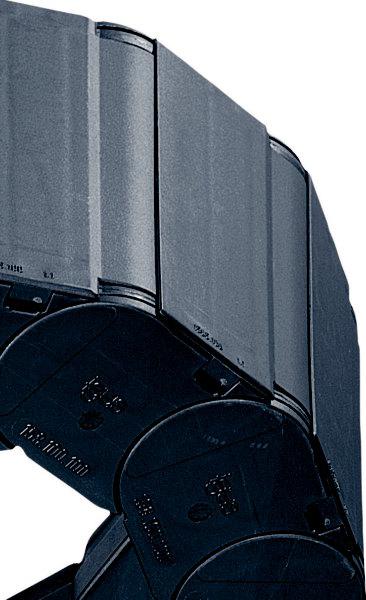
4 E2 R100 / R E2 e-tubes in chip-area of a tooling machine. Resistant against hot metal chips up to 850 C U-shaped supported e-tube for high lateral acceleration Standing application - R68 e-tube - Note: the first links are supported System RX - Extremely chip repellent e-tubes Totally redesigned igus e-tube - it repels chips, is extremely tight, and is still openable! System RX from page 6.50 Next Page Find Selection tables and assembly instructions 6.3
5 E2 e-tubes Protection against dirt and debris Material igumid G Snap-opens from the side, chip protected Covered pin/bore connection Lateral glide surface E2 Series R100 - robust and tight Very good protection against chips (including hot chips) Hinged, snap-open, removable lids along inner and outer radius reduce assembly time Space-efficient with optimized ratio of inner dimension to outer dimension Double stop dog for long service life and strong unsupported lengths Universal KM mounting brackets with attachment capability on all sides You can find more technical data about the material, chemical resistance, temperatures chapter Design, page 1.38 Selection table Series Inner height Inner width Outer width Outer height Bending radius Unsupported Page hi [mm] Bi [mm] Ba [mm] ha [mm] R [mm] length max. [m] R117/ , R157/ , R167/ , Large pins, long service life Material igumid G Removable lids along outer radius Easy ssembly E2 Series R - small pitch for smooth motion Protection for cables and hoses against chips (including hot chips) Small pitch for low noise, smooth operation Smooth, chip repelland exterior Lids removable for assembly time reduction Double stop dog for strong unsupported lengths KM mounting brackets with attachment capability on all sides Very small radii possible due to small pitch You can find more technical data about the material, chemical resistance, temperatures chapter Design, page 1.38 Selection table Series Inner height Inner width Outer width Outer height Bending radius Unsupported Page hi [mm] Bi [mm] Ba [mm] ha [mm] R [mm] length max. [m] R , R , R ,


6 E2 e-tubes ssembly Instructions Type R100 Series R117/R118 R157/R158 R167/R168 E2 R100 / R ssembling Type R Push, click - and snap in pin Swivel lids - push and snap Slide last lid Push and snap Separating Type R Lever open lid Bend e-tube to remove lid Release side-link Twist and pull apart Type R Series R48 R58 R68 ssembling Type R Push and click Snap in pin Slide lid Push and snap Separating Type R Lever open lid Remove lid Release side-link Twist and pull apart You can find an assembly video on the web 6.5

7 R117 R118 E2 e-tubes R100 Series R117 R Price index UL94-V2 classifications upon request if-design ward Winner Series R117/R118 e-tubes with HT-material for hot chips up to 850 C available upon request Effective chip protection, even against hot metal chips Smooth, chip-repellent exterior Double stop dog for strong unsupported length Snap-open from the side, covered pin/bore connection Lateral glide surfaces for side-mounted operation Snap-open lids along inner or outer radius Universal KM mounting brackets with attachment capability on all sides Space-efficient with optimized ratio of inner dimension to outer dimension To open the e-tube Series R100 lift up the lid and swivel lid to the side When to use the Series R117/R118: If snap-open accessibility along inner or outer radius is required If price is an issue If flush attachment is required When not to use it: For smoother running and smaller pitch e-tubes E2, Series R48, page 6.26 If no chip protection is required Series 1400/1500 E2/000, page Order example complete e-tube Please indicate e-tube-lengths or number of links Example: 1 m or 33 links 1 m e-tube with 2 separators assembled every 2 nd link Interior separation 1 set Mounting bracket 6.6 vailable from stock. Delivery in 24h or today! (Delivery time means time until shipping of goods)
8 E2 e-tubes R100 Series R117 R118 Dimensions and Technical Data R117 R118 Unsupported length FL G = with straight upper run FL B = with permitted sag Further information Design, page 1.12 HF H FL G FL B S (FL G ) S (FL B ) Fill weight [kg/m] FL B 0.5 FL G Unsupported length FL G / FL B [m] Length of travel S [m] S = Length of travel R = Bending radius H = Nominal clearence height H F = Required clearence height D = Overlength e-chain radius in final position K = π R + "safety" 21 E2 e-tubes Type R Inner height: 21 mm R S D S/2 37,4 Moving end Fixed end 30,5 30,6 28 H - 28 H H F = H + 25 Short travels - unsupported Unsupported e-chains feature positive camber over short travels. This must be accounted for when specifying the clearance height H F. Please consult igus if space is particularly restricted. Pitch = 30,5 mm/link Links/m = 33 (1000,6 mm) Chain length = S / 2 + K R H D K The required clearance height: H F = H + 25 mm (with 1,0 kg/m fill weight) Hot Chips up to 850 C e-tubes that repel hot chips, up to 850 ºC. Some applications, depending on amount and size of the chips, can burn or melt the surface. That is no longer the case with the igus "igumid HT" material. Order example - Full e-tube made of HT*: HT Order example - Lids made of HT: HT *for long travels upon request Delivery time up to 4 weeks! Further Information: Speed / acceleration FL G max. 10 [m/s] / max. 100 [m/s 2 ] Speed / acceleration FL B max. 3 [m/s] / max. 6 [m/s 2 ] Gliding speed / acceleration (maximum) max. 0,5 [m/s] / max. 5 [m/s 2 ] Material - permitted temperature C igumid G / -40 up to +120 C Flammability class, igumid G VDE 0304 IIC UL94 HB Technical Data Details of material properties page 1.38 page 6.5 3D-CD files, pdf-downloads and many online features
9 R117 R118 E2 e-tubes R100 Series R117 R118 Product Range Ba Bi Series R117 - hinged, snap-open on both sides of the inner radius Part No. Bi [mm] Ba [mm] R [mm] Bending radii Weight [kg/m] igus e-chainsystems 17 max. R , , , , , , ,06 Supplement Part No. with required radius. Example: = standard color, other colors page 1.39 Pitch = 30,5 mm/link - Links/m = 33 Part No. structure max. Ba Bi Color black Bending radius Width Series Series R118 - hinged, snap-open on both sides of the outer radius Part No. Bi [mm] Ba [mm] R [mm] Bending radii Weight [kg/m] , , , , , , ,06 igus GmbH Cologne R Part No. structure The sizes 020 / 038 / 063 / 100 are available upon request. Delivery time: approx weeks after receipt of order Supplement Part No. with required radius. Example: = standard color, other colors page 1.39 Pitch = 30,5 mm/link - Links/m = 33 Color black Bending radius Width Series Series R117 R118 ccessories Interior Separation Internet: info@igus.de 1,5 Vertical Separator 5 unassembled assembled Option 1: Vertical Separators Vertical Separators are used if a vertical subdivision of the e-chain interior is required - By standard Vertical Separators are assembled every other e-chain link Standard subdivision with Vertical Separator D-CD files, pdf-downloads and many online features
10 R100 Series R117 R118 ccessories Mounting Brackets, KM R117 R118 Option KM* - pivoting Pivoting Short and long travels Space-restricted Corrosion-resistant Pivoting option at fixed end available upon request (Part No ) *KM = Polymer Metal Mounting Bracket Moving end (outer link) Fixed end (inner link) Mounting bracket attachment Fixed end Moving end Dimensions and order configurations B Bi The mounting brackets are supplied with hexagon nuts and can be attached with M4 bolts, or the mounting brackets may also be attached with M4 socket head cap bolts. Part No. structure must be indicated on preassembled configurations Full set = 14 For Part No. Dim. Dim. B Width Series full set [mm] [mm] KM pivoting for selected chain type Please add the Part No. with the requested index - e.g For the preassembled mode please add the index e.g Full set, for both ends: Single-part order: Mounting bracket with bore Mounting bracket with pin 1 4 page 6.5 3D-CD files, pdf-downloads and many online features
11 R117 R118 R100 Series R117 R118 ccessories Mounting Brackets, ngled Moving end (outer link) ngled polymer bracket Locked connection to e-tube Minimized external width For long travels ttachment option for strain relief tiewrap plate PZ(B) Possible installation conditions for assembled mounting brackets Order example "preassembled" below PZ(B) Fixed end (inner link) Dimensions and order configurations Strain relief is possible on the moving end and/or the fixed end. Bi + 12 B 32 6,2 5, ,4 5, ,2 B Bi + 12 igus GmbH Cologne PZB PZB PZ PZB PZ PZB PZ PZB PZ PZB PZ PZB PZ Internet: info@igus.de PZ(B) Moving end PZ(B) Fixed end Part No. structure must be indicated on preassembled configurations with assembled tiewrap plates Full set = 14 Width Mounting brackets for selected chain type Full set, for both ends: PZB +tiewrap plate Single-part order: PZB +tiewrap plate Mounting bracket with bore PZB+tiewrap plate Mounting bracket with pin For Part No. Part No. Dim. Dim. B Series full set with full set without [mm] [mm] tiewrap plate tiewrap plate Please add the Part No. with the requested index - e.g PZB For the preassembled mode please add the index e.g PZB 1 The following parts are required for attachment of the mounting brackets: Countersunk bolt M5 DIN Length depends on the thickness of the attachment base Hexagon nut M5 DIN D-CD files, pdf-downloads and many online features
12 E2 e-tubes R100 Series R117 R118 ccessories Strain Relief R117 R118 Tiewrap No. of Dim. C Dim. B plate teeth n [mm] [mm] 2020.ZB ZB ZB ZB ZB ZB = (2030.ZB ZB) ZB ZB = (2050.ZB ZB) Tiewrap plate as individual part s individual component screwed on KM. Can be plugged in the mounting brackets. Details chapter 10 C B 2 8 (n-1) x 10 12/ Single tiewrap plate Shown assembled E2 e-tubes Type R Inner height: 21 mm Cable tiewraps as individual part Cable tiewraps (100-piece bag) Width x length max. Ø Tensile strength CFB.001 4,8 x 150 mm 36 mm 222 N Other strain relief elements chapter 10 chapter 10 page 6.5 3D-CD files, pdf-downloads and many online features
13 R157 R158 E2 e-tubes R100 Series R157 R Price index UL94-V2 classifications upon request ESD classification: Electrically conductive ESD/TEX version upon request e-tubes with HT-material for hot chips up to 850 C available upon request Snap-open lids along inner or outer radius Snap-open from the side, covered pin/bore connection Effective chip protection, even against hot metal chips Double stop dog for strong unsupported length Lateral glide surfaces for side-mounted operation Universal KM mounting brackets with attachment capability on all sides Space-efficient with optimized ratio of inner dimension to outer dimension Strain relief separator - Separator with integrated strain relief for the use in the first or last chain link page 6.18 To open the e-tube Series R100 lift up the lid and swivel lid to the side When to use the Series R157/R158: If snap-open accessibility along inner or outer radius is required If a low-cost, lightweight e-tube for many types of applications required If flush attachment is required If chip-repellent features are required When not to use it: For extremely chip repellent e-tubes System RX, Series RX32, page 6.58 If snap-open accessibility along both sides is required System E4.1, Series R4.32, page 7.42 If very smooth travel due to small pitch is required Type R, Series R58, page 6.34 Order example complete e-tube Please indicate e-tube-lengths or number of links Example: 1 m or 22 links 1 m e-tube with 2 separators assembled every 2 nd link Interior separation 1 set Mounting bracket 6.12 vailable from stock. Delivery in 24h or today! (Delivery time means time until shipping of goods)
14 E2 e-tubes R100 Series R157 R158 Dimensions and Technical Data R157 R158 Unsupported length FL G = with straight upper run FL B = with permitted sag Further information Design, page 1.12 HF H FL G FL B S (FL G ) S (FL B ) Fill weight [kg/m] FL G FL B Unsupported length FL G / FL B [m] Length of travel S [m] S = Length of travel R = Bending radius H = Nominal clearence height H F = Required clearence height D = Overlength e-chain radius in final position K = π R + "safety" 40 E2 e-tubes Type R Inner height: 40 mm R D Moving end Fixed end S H-50 H H F = H + 40 Short travels - unsupported Unsupported e-chains feature positive camber over short travels. This must be accounted for when specifying the clearance height H F. Please consult igus if space is particularly restricted. Pitch = 46 mm/link Links/m = 22 (1012 mm) Chain length = S / 2 + K R H D K The required clearance height: H F = H + 40 mm (with 1,0 kg/m fill weight) Hot Chips up to 850 C e-tubes that repel hot chips, up to 850 ºC. Some applications, depending on amount and size of the chips, can burn or melt the surface. That is no longer the case with the igus "igumid HT" material. Order example - Full e-tube made of HT*: HT Order example - Lids made of HT: HT *for long travels upon request Delivery time up to 4 weeks! Further Information: Speed / acceleration FL G max. 10 [m/s] / max. 100 [m/s 2 ] Speed / acceleration FL B max. 3 [m/s] / max. 6 [m/s 2 ] Gliding speed / acceleration (maximum) max. 0,5 [m/s] / max. 5 [m/s 2 ] Material - permitted temperature C igumid G / -40 up to +120 C Flammability class, igumid G VDE 0304 IIC UL94 HB Technical Data Details of material properties page 1.38 page 6.5 3D-CD files, pdf-downloads and many online features
15 R157 R158 E2 e-tubes R100 Series R157 R158 Product Range igus e-chainsystems 37 max. Ba Bi R Series R157 - hinged, snap-open on both sides of the inner radius Part No. Bi [mm] Ba [mm] R [mm] Bending radii Weight [kg/m] * , , , , ** , , , , , , ,55 igus GmbH Cologne Part No. structure max. Ba Bi R Color black Bending radius Width Series * Lid removable only, not hinged ** Same dimensions as less recent design, no hinged option Supplement Part No. with required radius. Example: = standard color, other colors page 1.39 Pitch = 46 mm/link - Links/m = 22 Series R158 - hinged, snap-open on both sides of the outer radius Part No. Bi [mm] Ba [mm] R [mm] Bending radii Weight [kg/m] * , , , , ** , , , , , , ,55 Internet: info@igus.de Part No. structure Color black Bending radius Width Series * Lid removable only, not hinged ** Same dimensions as less recent design, no hinged option The size 125 is available upon request. Delivery time: approx weeks after receipt of order Supplement Part No. with required radius. Example: = standard color, other colors page 1.39 Pitch = 46 mm/link - Links/m = D-CD files, pdf-downloads and many online features
16 E2 e-tubes R100 Series R157 R158 ccessories Interior Separation R157 R158 Option 1: Vertical Separators Vertical Separators are used if a vertical subdivision of the e-chain interior is required - By standard Vertical Separators are assembled every other e-chain link Standard subdivision with Vertical Separator symetrical Separator for side-mounted operations Strain Relief Separator Z, integrable in the mounting bracket, to postition at any point - can be combined with Full-Width Shelf 221.X and Shelf 2210.X 3 Vertical Separator unassembled assembled symetrical Separator unassembled ,5 assembled Strain Relief Separator unassembled Z assembled Z E2 e-tubes Type R Inner height: 40 mm Option 2: Full-Width Shelves For applications involving many thin cables with similar or identical diameters Vertical Separator, slotted for applications with Full-Width Shelf 221.X X Width Part No. Part No. Width Part No. Part No. X [mm] unassembled assembled X [mm] unassembled assembled Vert. Separator, slotted unassembled assembled Full-Width Shelf X t = 2,5 Option 3: Shelves Middle Plate 4 For applications involving many cables with similar or identical diameters. Partial separation unassembled into individual chambers can be achieved and the entire width Bi-10 mm can be used Shelf 2210.X can be combined with Middle Plate assembled mm 2210.X Width Part No. Part No. Width Part No. Part No. X [mm] unassembled assembled X [mm] unassembled assembled Shelf X X - 7 t = 2,5 page 6.5 3D-CD files, pdf-downloads and many online features
17 R157 R158 Series R157 R158 ccessories Mounting Brackets KM, Extended The attachment variants arising automatically by the choice of the KM mounting bracket Option KM* - pivoting, extended Recommended for unsupported and gliding applications Extended, pivoting Easy to install Universally mountable with attachment capability on all sides Locked connection to e-tube Long travels with lowered mounting height possible *KM = Polymer Metal Mounting Bracket Moving end (outer link) 15800/ depending on radius 15800/ Fixed end (inner link) 26 The attachment variants arising automatically by the choice of the KM mounting bracket Option KM - locking, extended Recommended for vertical hanging / standing applications Extended, locking Easy to install Flush mounting at both ends of the e-tube Universally mountable with attachment capability on all sides Corrosion-resistant Moving end (outer link) 15800/ / Fixed end (inner link) Dimensions and order configurations Quickflange upon request Part No. structure (pivoting) 15800/ Standard! (pivoting) Standard! (pivoting) 15800/ / (locking) (locking) 15800/ Moving end Fixed end Quickflange available upon request igus GmbH Cologne Internet: info@igus.de Full set, for both ends: Single-part order: Full set, for both ends: Single-part order: Mounting bracket with bore Mounting bracket with pin must be indicated on preassembled configurations Full set pivoting = 12 Width KM for selected chain type Mounting bracket with bore Mounting bracket with pin Part No. structure (locking) must be indicated on preassembled configurations Full set locking = 34 Width KM for selected chain type B For Part No. Dim. Dim. B Series full set [mm] [mm] Please add the Part No. with the requested index - 12 for the pivoting configuration e.g or 34 for the locking configuration e.g For the preassembled mode please add the index e.g The following parts are required for attachment of the mounting brackets: Socket head cap bolt M5 DIN Length depends on the thickness of the attachment base Washer 5,3 DIN 125-ST Hexagon nut M5 DIN B 6.16 Strain relief separator for the use in the first or last chain link page 6.18
18 Series R157 R158 ccessories Mounting Brackets, KM, bbreviated R157 R158 Option KM* - pivoting, abbreviated Recommended for unsupported and gliding applications bbreviated, pivoting Universally mountable with attachment capability on all sides Locked connection to e-tube Corrosion-resistant Space-restricted Long travels with lowered mounting height possible * KM = Polymer Metal Mounting Bracket Moving end (outer link) depending on radius Fixed end (inner link) The attachment variants arising automatically by the choice of the KM mounting bracket Option KM - locking, abbreviated Recommended for vertical hanging / standing applications bbreviated, locking Flush mounting at both ends of the e-tube Corrosion-resistant Flush mounting, turned 90 at fixed end option Moving end (outer link) depending on radius Fixed end (inner link) The attachment variants arising automatically by the choice of the KM mounting bracket (pivoting) (pivoting) (locking) (locking) Moving end Fixed end Quickflange available upon request Dimensions and order configurations Quickflange upon request Part No. structure (pivoting) B B must be indicated on preassembled configurations Full set Width 45,4 11,1 22 For Part No. Dim. Dim. B Series full set [mm] [mm] Please add the Part No. with the requested index for the pivoting configuration e.g or 1585 for the locking configuration e.g For the preassembled mode please add the index e.g The following parts are required for attachment of the mounting brackets: Socket head cap bolt M5 DIN Length depends on the thickness of the attachment base Washer 5,3 DIN 125-ST Hexagon nut M5 DIN Full set, for both ends: Single-part order: Mounting bracket with bore Mounting bracket with pin must be indicated on preassembled configurations Full set Width Full set, for both ends: Single-part order: KM locking for selected chain type Mounting bracket with bore Part No. structure (locking) KM pivoting for selected chain type Mounting bracket with pin page 6.5 Strain relief separator for the use in the first or last chain link page
19 R157 R158 Series R157 R158 ccessories Mounting Brackets, Steel, Flange Flush mounting possibilities at both ends of the e-tube Flange mounting brackets made of steel Metallic flange brackets with popular hole patterns, easily be replaced by their modern successors, without having to alter the hole pattern Bolted connection outside of chain cross-section possible Universally mountable with attachment capability on all sides Steel, galvanized One-piece mounting bracket High stability Moving end (outer link) X X Fixed end (inner link) Dimensions and order configurations Hole patterns flange steeel mounting brackets X X Moving end X Fixed end igus GmbH Cologne Principle sketch flange steeel mounting brackets Mounting only with hexagon socket DIN 912 M6 and washer DIN 125, 6,3 mm Z x t = 2 Ba Part No. Number of teeth For Series Z 3 both sides R157/ B = Ba x ø4,2 For Hole Part No. Bi Ba Dim. Dim. B Series pattern full set [mm] [mm] [mm] [mm] R100 Series R157 R158 ccessories Strain Relief Strain relief separator Separator with integrated strain relief, for use in the first or last chain link. For manufacturing of switchgear cabinets or for the assembly of machines. Easy to assemble without any fastening device. Separator base Z is 22 mm wide. The possible number of separators per e-chain is defined by its inner width Bi and by the cable-diameter. Details chapter 10 e-tube 50 Internet: info@igus.de Other strain relief elements chapter 10 Bi max. Strain Relief Separator - The number of seperators is depending on the cables and the available inner space. Example: e-chain inner width Bi 100 mm: 4 Strain Relief Separator, max. cable diameter 16 mm. Details chapter D-CD files, pdf-downloads and many online features


20 R100 Series R157 R158 pplications R157 R158 E2 e-tubes Type R Inner height: 40 mm igus e-tubes Series R100 in a medical application chapter 10 page 6.5 3D-CD files, pdf-downloads and many online features

21 R167 R168 E2 e-tubes R100 Series R167 R Price index UL94-V2 classifications upon request ESD classification: Electrically conductive ESD/TEX version upon request e-tubes with HT-material for hot chips up to 850 C available upon request Double stop dog for strong unsupported length Effective chip protection, even against hot metal chips Covered pin/bore connection Lateral glide surfaces for side-mounted operation Snap-open lids along inner or outer radius Lids can be swivelled from the left to the right Space-efficient with optimized ratio of inner dimension to outer dimension Universal KM mounting brackets with attachment capability on all sides Strain relief separator - Separator with integrated strain relief for the use in the first or last chain link page 6.25 To open the e-tube Series R100 lift up the lid and swivel lid to the side When to use the Series R167/R168: If snap-open accessibility along inner or outer radius is required If a low-cost, lightweight e-tube for many types of applications required If flush attachment is required If chip-repellent features are required When not to use it: For extremely chip repellent e-tubes System RX, Series RX40, page 6.64 If snap-open accessibility along both sides is required System E4.1, Series R4.42, page 7.60 If very smooth travel due to small pitch is required Type R, Series R68, page 6.42 Order example complete e-tube Please indicate e-tube-lengths or number of links Example: 1 m or 17 links 1 m e-tube with 2 separators assembled every 2 nd link Interior separation 1 set Mounting bracket 6.20 vailable from stock. Delivery in 24h or today! (Delivery time means time until shipping of goods)
22 E2 e-tubes R100 Series R167 R168 Dimensions and Technical Data R167 R168 Unsupported length FL G = with straight upper run FL B = with permitted sag Further information Design, page 1.12 HF H FL G FL B S (FL G ) S (FL B ) Fill weight [kg/m] FL G FL B Unsupported length FL G / FL B [m] Length of travel S [m] S = Length of travel R = Bending radius H = Nominal clearence height H F = Required clearence height D = Overlength e-chain radius in final position K = π R + "safety" 50 E2 e-tubes Type R Inner height: 50 mm R D Moving end S S/2 Fixed end H - 64 H H F = H + 40 Short travels - unsupported Unsupported e-chains feature positive camber over short travels. This must be accounted for when specifying the clearance height H F. Please consult igus if space is particularly restricted. Pitch = 58,8 mm/link Links/m = 17 (999,6 mm) Chain length = S / 2 + K R H D K The required clearance height: H F = H + 40 mm (with 2,0 kg/m fill weight) Hot Chips up to 850 C e-tubes that repel hot chips, up to 850 ºC. Some applications, depending on amount and size of the chips, can burn or melt the surface. That is no longer the case with the igus "igumid HT" material. Order example - Full e-tube made of HT*: HT Order example - Lids made of HT: HT *for long travels upon request Delivery time up to 4 weeks! Further Information: Speed / acceleration FL G max. 10 [m/s] / max. 100 [m/s 2 ] Speed / acceleration FL B max. 3 [m/s] / max. 6 [m/s 2 ] Gliding speed / acceleration (maximum) max. 0,5 [m/s] / max. 5 [m/s 2 ] Material - permitted temperature C igumid G / -40 up to +120 C Flammability class, igumid G VDE 0304 IIC UL94 HB Technical Data Details of material properties page 1.38 page 6.5 3D-CD files, pdf-downloads and many online features
23 R167 R168 E2 e-tubes R100 Series R167 R168 Product Range igus e-chainsystems 46 max. Ba Bi R Series R167 - hinged, snap-open on both sides of the inner radius Part No. Bi [mm] Ba [mm] R [mm] Bending radii Weight [kg/m] , , , , , , , , , ,62 igus GmbH Cologne Part No. structure max. Ba Bi R Part No. structure Part No. Bi [mm] Ba [mm] R [mm] Bending radii Weight [kg/m] , , , , , , ,86 Internet: info@igus.de Color black Bending radius Width Series Color black Bending radius Width Series Supplement Part No. with required radius. Example: = standard color, other colors page 1.39 Pitch = 58,8 mm/link - Links/m = 17 Series R168 - hinged, snap-open on both sides of the outer radius , , ,62 The sizes 125 / 225 / 250 are available upon request. Delivery time: approx weeks after receipt of order Supplement Part No. with required radius. Example: = standard color, other colors page 1.39 Pitch = 58,8 mm/link - Links/m = D-CD files, pdf-downloads and many online features
24 E2 e-tubes R100 Series R167 R168 ccessories Interior Separation R167 R168 Option 1: Vertical Separators Vertical Separators are used if a vertical subdivision of the e-chain interior is required - By standard Vertical Separators are assembled every other e-chain link Standard subdivision with Vertical Separator Strain Relief Separator Z, integrable in the mounting bracket, to postition at any point - can be combined with Full-Width Shelf 321.X and Shelf 2210.X Vertical Separator unassembled assembled Strain Relief Separator unassembled Z assembled Z E2 e-tubes Type R Inner height: 50 mm Option 2: Full-Width Shelves For applications involving many thin cables with similar or identical diameters Vertical Separator, slotted for applications with Full-Width Shelf 321.X X Width Part No. Part No. Width Part No. Part No. X [mm] unassembled assembled X [mm] unassembled assembled Vert. Separator, slotted Full-Width Shelf X - 1 t = 3, unassembled assembled Option 3: Shelves For applications involving many cables with similar or identical diameters. Partial separation into individual chambers can be achieved and the entire width Bi-10 mm can be used Shelf 2210.X can be combined with Middle Plate and Side Plate Middle Plate unassembled assembled Side Plate unassembled assembled X mm Width Part No. Part No. X [mm] unassembled assembled Width Part No. Part No. X [mm] unassembled assembled Shelf X X - 7 t = 2,5 page 6.5 3D-CD files, pdf-downloads and many online features
25 R167 R168 Series R167 R168 ccessories Mounting Brackets, KM The attachment variants arising automatically by the choice of the KM mounting bracket Option KM* - pivoting Recommended for unsupported and gliding applications Option - KM with Quickflange, bolted connection outside of e-tube cross-section Universally mountable with attachment capability on all sides Locked connection to e-tube Long travels with lowered mounting height possible Corrosion-resistant *KM = Polymer Metal Mounting Bracket Moving end (outer link) depending on radius Fixed end (inner link) The attachment variants arising automatically by the choice of the KM mounting bracket Option KM - locking Recommended for vertical hanging / standing applications Option - KM with Quickflange, bolted connection outside of e-tube cross-section t very high speed and acceleration Universally mountable with attachment capability on all sides Flush mounting at both ends of the e-tube Moving end (outer link) depending on radius Fixed end (inner link) Dimensions and order configurations Quickflange upon request Part No. structure (pivoting) 26 Quickflange Standard! (pivoting) Standard! (pivoting) (locking) (locking) Moving end Fixed end igus GmbH Cologne Internet: info@igus.de Part No. structure (locking) must be indicated on preassembled configurations Full set locking = 14 Width Full set, for both ends: Single-part order: KM for selected chain type Mounting bracket with bore Mounting bracket with pin must be indicated on preassembled configurations Full set pivoting = 12 Width Full set, for both ends: Single-part order: KM for selected chain type Mounting bracket with bore Mounting bracket with pin Bi 12 B For Part No. Part No. full set Dim. Dim. B Series full set with Quickflange [mm] [mm] QF QF QF QF QF QF QF QF QF QF Please add the Part No. with the requested index - 12 for the pivoting configuration e.g or 14 for the locking configuration e.g For the preassembled mode please add the index e.g Quickflange unassembled: Part No QF The following parts are required for attachment of the mounting brackets: Socket head cap bolt M5 DIN Length depends on the thickness of the attachment base Washer 5,3 DIN 125-ST Hexagon nut M5 DIN B 6.24 Strain relief separator for the use in the first or last chain link page 6.25
26 Series R167 R168 ccessories Mounting Brackets, Steel, Flange R167 R168 Flange mounting brackets made of steel Metallic flange brackets with popular hole patterns, easily be replaced by their modern successors, without having to alter the hole pattern Bolted connection outside of chain cross-section possible Universally mountable with attachment capability on all sides Steel, galvanized One-piece mounting bracket High stability Moving end (outer link) X X Fixed end (inner link) Flush mounting possibilities at both ends of the e-tube Hole patterns flange steeel mounting brackets X X Moving end X Fixed end Dimensions and order configurations x t = 2 Ba B = Ba x ø4,2 For Hole Part No. Bi Ba Dim. Dim. B Series pattern full set [mm] [mm] [mm] [mm] R R R Principle sketch flange steeel mounting brackets Mounting only with hexagon socket DIN 912 M6 and washer DIN 125, 6,3 mm R100 Serie R167 R168 ccessories Strain Relief Strain relief separator Separator with integrated strain relief, for use in the first or last chain link. For manufacturing of switchgear cabinets or for the assembly of machines. Easy to assemble without any fastening device. Separator base Z is 22 mm wide. The possible number of separators per e-chain is defined by its inner width Bi and by the cable-diameter. Details chapter 10 Part No. Number of teeth For Series Z 4 both sides R167/168 e-tube Z chapter 10 Bi max. Strain Relief Separator - The number of seperators is depending on the cables and the available inner space. Example: e-chain inner width Bi 100 mm: 4 Strain Relief Separator, max. cable diameter 16 mm. Details chapter 10 Other strain relief elements chapter 10 page 6.5 3D-CD files, pdf-downloads and many online features
27 R48 25 E2 e-tubes R Series R48 Price index UL94-V2 classifications upon request ESD classification: Electrically conductive ESD/TEX version upon request e-tubes with HT-material for hot chips up to 850 C available upon request Protection for cables and hoses, against hot chips Removable lids along outer radius Large pins for high stability Smooth, chip-repellent exterior Small pitch for low-noise, smooth operation Fully enclosed KM mounting brackets with attachment capability on all sides Strain relief separator - Separator with integrated strain relief for the use in the first or last chain link page 6.32 To open the e-tube Series R lift up the lid (with a screwdriver) and remove the lid When to use the Series R48: If particularly quiet operation is required t very high speed If chip-repellent features are required When not to use it: For extremely chip repellent e-tubes System RX, Series RX32, page 6.58 If a particularly low-cost solution is the main factor Series R117/R118, page 6.6 If no chip protection is required Series 2400/2500 E2/000, page Order example complete e-tube Please indicate e-tube-lengths or number of links Example: 1 m or 33 links 1 m e-tube with 2 separators 482 assembled every 2 nd link Interior separation 1 set Mounting bracket 6.26 vailable from stock. Delivery in 24h or today! (Delivery time means time until shipping of goods)
28 E2 e-tubes R Series R48 Dimensions and Technical Data R48 Unsupported length FL G = with straight upper run FL B = with permitted sag Further information Design, page 1.12 HF H D S/2 R S (FL G ) S (FL B ) 30.3 FL G FL B S Moving end Fixed end FL G FL B Unsupported length FL G / FL B [m] Length of travel S [m] Pitch = 30,3 mm/link Links/m = 33 (999,9 mm) Chain length = S / 2 + K R H D K H * D * K * *upon request Fill weight [kg/m] H - 36 H H F = H + 20 S = Length of travel R = Bending radius H = Nominal clearence height H F = Required clearence height H RI = Trough inner height D = Overlength e-chain radius in final position K = π R + "safety" D 2 = Over length - long travels, gliding K 2 = *Further add-on H 2 = *Mounting height *if the mounting bracket location is set lower Other installation methods Vertical, hanging 50 m Vertical, standing 4 m Side mounted, unsupp. 1,5 m Rotary requires further calculation Unsupported length of upper run = upon request Short travels - unsupported Unsupported e-chains feature positive camber over short travels. This must be accounted for when specifying the clearance height H F. Please consult igus if space is particularly restricted. The required clearance height: H F = H + 20 mm (with 0,5 kg/m fill weight) 25 E2 e-tubes Type R Inner height: 25 mm Long travel lengths from 5,0 m to max. 50 m Chain length = S / 2 + K 2 S S/2 S/2 Moving end Fixed end H2 D2 K2 Guide trough with glide bar Guide trough without glide bar Total length of guide trough In case of travels between 2,0 and 5,0 m we recommend a longer unsupported length. R HRI Gliding, long travel applications (max. 50 m) In this case the e-chain upper run will be introduced in a guide trough on the lower run. We recommend to realize the engineering of such a plant by our technicians. Speed / acceleration FL G max. 10 [m/s] / max. 100 [m/s 2 ] Speed / acceleration FL B max. 3 [m/s] / max. 6 [m/s 2 ] Gliding speed / acceleration (maximum) max. 3 [m/s] / max. 10 [m/s 2 ] Material - permitted temperature C igumid G / -40 up to +120 C Flammability class, igumid G VDE 0304 IIC UL94 HB Technical Data Details of material properties page 1.38 page 6.5 3D-CD files, pdf-downloads and many online features
29 R48 E2 e-tubes R Series R48 Product Range Series R48 - snap-open along outer radius Part No. Bi [mm] Ba [mm] R [mm] Bending radii Weight [kg/m] igus e-chainsystems 22 max. R Bi Ba , , , , ,46 Supplement Part No. with required radius. Example: = standard color, other colors page 1.39 Pitch = 30,3 mm/link - Links/m = Part No. structure Color black Bending radius Width Series 2,5 Vertical Separator unassembled 481 assembled ,5 Strain Relief Separator unassembled 481.ZR assembled 482.ZR 10 E2 e-tubes R Series R48 ccessories Interior Separation Option 1: Vertical Separators Vertical Separators are used if a vertical subdivision of the e-chain interior is required - By standard Vertical Separators are assembled every other e-chain link Standard subdivision with Vertical Separator 482 Strain Relief Separator 482.ZR, integrable in the mounting bracket, to postition at any point igus GmbH Cologne 482 Internet: info@igus.de Hot Chips up to 850 C e-tubes that repel hot chips, up to 850 ºC. Some applications, depending on amount and size of the chips, can burn or melt the surface. That is no longer the case with the igus "igumid HT" material. Order example - Full e-tube made of HT*: HT Order example - Lids made of HT: HT *for long travels upon request Delivery time up to 4 weeks! Further Information: D-CD files, pdf-downloads and many online features
30 E2 e-tubes R Series R48 ccessories Mounting Brackets, KM R48 Option KM* - pivoting Recommended for unsupported applications Bolted connection outside of chain cross-section possible Space-restricted Universally mountable with attachment capability on all sides Mounting-surfaces can be used on the upper side or front-sided *KM = Polymer Metal Mounting Bracket Moving end (outer link) Fixed end (inner link) The attachment variants arising automatically by the choice of the KM mounting bracket Option KM - locking Recommended for vertical hanging / standing applications Bolted connection outside of chain cross-section possible t very high speed and acceleration Universally mountable with attachment capability on all sides Mounting-surfaces can be used on the upper side or front-sided Moving end (outer link) Fixed end (inner link) The attachment variants arising automatically by the choice of the KM mounting bracket (pivoting) (pivoting) (locking) (locking) Moving end Fixed end Dimensions and order configurations 5 Part No. structure (pivoting) must be indicated on preassembled configurations Full set ,5 B Width Full set, for both ends: Single-part order: KM pivoting for selected chain type Mounting bracket with bore Mounting bracket with pin For Part No. Dim. Dim. B Series full set [mm] [mm] Please add the Part No. with the requested index for the pivoting configuration e.g or 485 for the locking configuration e.g For the preassembled mode please add the index e.g The following parts are required for attachment of the mounting brackets: Socket head cap bolt M5 DIN Length depends on the thickness of the attachment base Washer 5,3 DIN 125-ST Hexagon nut M5 DIN Part No. structure (locking) must be indicated on preassembled configurations Full set Width Full set, for both ends: Single-part order: KM locking for selected chain type Mounting bracket with bore Mounting bracket with pin page 6.5 Strain relief separator for the use in the first or last chain link page
31 R48 E2 e-tubes R Series R48 ccessories Mounting Brackets, Steel Steel mounting bracket Locked connection to e-tube Electrically conductive Minimized external width Moving end (outer link) Possible installation conditions - Further installation angles installation sketch Fixed end (inner link) Dimensions and order configurations Moving end Fixed end 40 Bi t = 2 t = 2 t= Part No. structure For Part No. Dim. Series full set [mm] igus GmbH Cologne Full set, for both ends: Single-part order: must be indicated on preassembled configurations Full set = 12 Width Mounting brackets for selected chain type Mounting bracket with bore Please add the Part No. with the requested index - e.g For the preassembled mode please add the index e.g The following parts are required for attachment of the mounting brackets: Socket head cap bolt M5 DIN Length depends on the thickness of the attachment base Washer 5,3 DIN 125-ST Hexagon nut M5 DIN Internet: info@igus.de Mounting bracket with pin 6.30 Strain relief separator for the use in the first or last chain link page 6.32
32 E2 e-tubes R Series R48 ccessories Mounting Brackets, ngled R48 ngled polymer bracket ttachment option for strain relief tiewrap plate Locked connection to e-tube Minimized external width Moving end (outer link) (PZB) (PZB) Fixed end (inner link) Possible installation conditions for assembled mounting brackets Order example "preassembled" below (PZB) Moving end (PZB) Fixed end Dimensions and order configurations Bi + 10 B 32 6, ,5 For Part No. Part No. Dim. Dim. B Series Full set with Full set without [mm] [mm] tiewrap plates tiewrap plates PZB PZB PZB PZB Please add the Part No. with the requested index - e.g PZB For the preassembled mode please add the index e.g PZB 1 The following parts are required for attachment of the mounting brackets: Countersunk bolt M5 DIN Length depends on the thickness of the attachment base Hexagon nut M5 DIN , ,2 B Bi + 10 Strain relief is possible on the moving end and/or the fixed end. Part No. structure PZB1 Full set, for both ends: PZB Single-part order: must be indicated on preassembled configurations with assembled tiewrap plates Full set = 12 Width Mounting brackets for selected chain type Mounting bracket with bore PZB 2 PZB Mounting bracket with pin page 6.5 Strain relief separator for the use in the first or last chain link page
33 R48 E2 e-tubes R Series R48 ccessories Strain Relief igus e-chainsystems Single tiewrap plate Shown assembled 6.2 Tiewrap plate as individual part s individual component screwed on KM. Can be plugged in the mounting brackets. Details chapter 10 C B 2 8 (n-1) x 10 12/ Tiewrap No. of Dim. C Dim. B plate teeth n [mm] [mm] 2020.ZB ZB ZB ZB ZB ZB = (2030.ZB ZB) ZB ZB = (2050.ZB ZB) ZR Cable tiewraps as individual part Cable tiewraps (100-piece bag) Width x length max. Ø Tensile strength CFB.001 4,8 x 150 mm 36 mm 222 N Strain relief separator Separator with integrated strain relief, for use in the first or last chain link. For manufacturing of switchgear cabinets or for the assembly of machines. Easy to assemble without any fastening device. Separator base 481.ZR is 10 mm wide. The possible number of separators per e-chain is defined by its inner width Bi and by the cable-diameter. Details chapter 10 Part No. Number of teeth For Series 481.ZR 2 both sides R48 e-tube Bi 10 igus GmbH Cologne Other strain relief elements chapter ,0 max. 10 Strain Relief Separator - The number of seperators is depending 3,5 on the cables and the available inner space. Example: e-chain inner width Bi 50 mm: 3 Strain Relief Separator, max. cable diameter 8 mm. Details chapter 10 Internet: info@igus.de D-CD files, pdf-downloads and many online features
34 Part No SL SL Trough height: 87 mm luminum "SuperTrough" Basic Version R Bottom clamp attached optionally inwards or outwards M6 x16 B Ra B Ri Ba + 4 Ba Bi ha 4, H Ri 2 x ha H Ra = 87 Length of the C-profile according to dimension B Ri see table Components, trough "Basic": Trough side parts, aluminum, 2 m Glide bar, plastic, 2 m Glide strips, plastic, 2 m (without glide strips on request) Optional: Silencer profile, rubber Components, installation set "Basic": Bottom clamp, aluminum C-profile, steel galvanized Screw M6 x16 Sliding nut M6 Interface connector, plastic Ba Bi ha = Outer width e-chains / e-tube = Inner width e-chains / e-tube = Outer height e-chains / e-tube H Ri = Inner trough height H Ra = Outer trough height B Ri = Inner trough width depends on dim. Ba B Ra = Outer trough width n Mon = Number of installation sets (left/right) n Ri = Number of troughs sets (left/right) H! Ri 2 ha B Ri Ba + 4 = Guide trough set = Glide bar = Installation set "Basic" = C-profile Installation set "Basic" with C-profile Bottom Clamp attached optionally inwards or outwards Order example Part No. Part No. B Ri attached attached [mm] inwards outwards Order example: Length of travel 30 m - Center mounted for Series with B Ri = 115 Guide trough set (set of 2 trough side parts, incl. glide strips) without glide bar Order text: 16 m guide trough without glide bar (8 x 2 m sections) Part No. Guide trough set (set of 2 trough side parts, incl. glide strips) with glide bar Order text: 16 m guide trough with glide bar (8 x 2 m sections) Installation set "Basic" complete (guide trough-sets + 1) Order text: 17 installation sets "Basic" Option: For an additional noise dampening with silencer profile, please add Index - Example: Part No SL SL Part No Part No SL Insert for the installation set "Heavy Duty": XXX instead of ( XXX) on the right column "attached outwards" n Mon = n Ri + 1 n Ri x 2000 mm Principle sketch: Number of installation sets to be installed = Number of trough sections + 1 Other guide trough systems chapter 10 chapter 9 "Heavy Duty" for heavy plant construction with glide bar and silencer profiles chapter 9 "Steel trough" very stable and robust guide trough out of steel, 2 pieces, adjustable on chain width chapter 9 page 6.5 Details about lu "SuperTrough" and further guidance possibilities chapter 9, Guide Troughs 6.33

35 R58 35 E2 e-tubes R Series R58 Price index UL94-V2 classifications upon request ESD classification: Electrically conductive ESD/TEX version upon request e-tubes with HT-material for hot chips up to 850 C available upon request Protection for cables and hoses, against hot chips Large pins for high stability Removable lids along outer radius Smooth, chip-repellent exterior Small pitch for low-noise, smooth operation Fully enclosed KM mounting brackets with attachment capability on all sides Small pitch enables very small radii Integrated strain relief available especially for e-tubes page 6.40 To open the e-tube Series R lift up the lid (with a screwdriver) and remove the lid When to use the Series R58: If particularly quiet operation is required t very high speed If chip protection is subject to stringent requirements When not to use it: If a particularly low-cost solution is the main factor Series R157/158, page 6.12 If no chip protection is required Series 2600/2700 E2/000, page Order example complete e-tube Please indicate e-tube-lengths or number of links Example: 1 m or 56 links 1 m e-tube with 2 separators 582 assembled every 2 nd link Interior separation 1 set Mounting bracket 6.34 vailable from stock. Delivery in 24h or today! (Delivery time means time until shipping of goods)
E2/000 Series
 E2/000 Series 35 35 Price index IPA Qualification Certificate Air Cleanless Class ISO Class 3 (at v = 2 m/s) upon request ESD classification: Electrically conductive ESD/ATEX version upon request UL94
easy chain Series E200 Z200
 easy chain Series Price index IPA Qualification Certificate: Air Cleanless Class ISO Class 2 (at v = 1 m/s) upon request UL94-V2 classifications Torsional motion possible Special equipment: Electrically
easy chain Series E26 Z26
 easy chain Series 36,5 36,5 Price index IPA Qualification Certificate: Air Cleanless Class ISO Class 2 (at v = 1 m/s) upon request UL94-V2 classifications Torsional motion possible Special equipment: Electrically
E2/
 1400 E2/000 1400 21 21 Price index IPA Qualification Certificate Air Cleanless Class ISO Class 3 (at v = 2 m/s) upon request ESD classification: Electrically conductive ESD/ATEX version upon request UL94
Energy Chain System E2 Medium Series 200/240/250
 Energy Chain System E2 Medium //.98.98.98 Price Index Features & Benefits Dirt-repellent contoured exterior // Cable-friendly, smooth interior with modular interior separation Special Features / Options
02A)-D-EU-IT-TRIFLEX SOLO- G :25 Uhr Seite 30 for 3D-applications easy triflex 2.30
-D-EU-IT-TRIFLEX SOLO- G :25 Uhr Seite 30 for 3D-applications easy triflex 2.30") for 3D-applications easy triflex 2.30 2.31 easy triflex - e-chain for 3D-applications The triflex Series was developed to realize safe energy supply in the case of multi-dimensional movements. In doing
for 3D-applications easy triflex 2.30 2.31 easy triflex - e-chain for 3D-applications The triflex Series was developed to realize safe energy supply in the case of multi-dimensional movements. In doing
E2 Medium - E-Chains with 2-part link design for a wide range of applications
 igus E2 Medium E2 Medium - E-Chains with 2-part link design for a wide range of applications E2 Medium - the standard The E2 Medium Series is the largest of the E2 family of E-Chains features snap-open
E2 mini Series 10 Introduction
 E2 mini Series Introduction 18 Stable and cost-effective Mounting bracket with strain relief option One-piece design, non snap-open Lightweight and stable Large pin for high stability When to use the Series
Series 17 Introduction
 zipper e-chains Series Introduction 3 Mounting bracket with strain relief option e-chain zip-open along outer radius Fast opening, large inner height When to use Series E mini: If an e-chain with an inner
Quick, zipper-like installation
 07 Product Range: Series 07 "Zipper" 10,3 igus Energy Chain Systems Price Index 8 Widths 3 Bending Radii Product Range: Inner Widths (Bi) in mm: 6, 10, 16, 20, 30, 40, 50, 64 Bending Radii (R) in mm: 018,
E2 mini Series 14 Introduction
 E2 mini Series Introduction 20 Mounting bracket with strain relief option Snap-open along inner radius When to use the Series E2 mini: If an e-chain with an inner height of 20 mm and small bending radii
Series 09 Introduction
 09 zipper e-chains Series 09 Introduction Mounting bracket with strain relief option e-chain zip-open along outer radius Lightweight and stable For high accelerations Small pitch for low-noise, smooth
Energy Chain Systems E2 medium
 Energy Chain Systems E2 medium E2 medium Series // Series 26/27/27i Series 340/350* *Extender chain 2 parts per link, maximum Easy installation Many connection options Long service life High stability
07) D-US SYSTEM E4 204S :57 Uhr Seite
 D-US SYSTEM E4 204S :57 Uhr Seite") 7.0 E4 7.1 System E4 4-piece E-Chains Modular and robust E4/00 Standard System E4/00 Your first choice in E4 - The standard broad application spectrum Low noise - Noise reduction with TÜV certificate (Series
7.0 E4 7.1 System E4 4-piece E-Chains Modular and robust E4/00 Standard System E4/00 Your first choice in E4 - The standard broad application spectrum Low noise - Noise reduction with TÜV certificate (Series
E6 Series E6.52 R6.52 Delivery program Extremely low-noise, minimum vibration, medium size
 E6 Series Delivery program Extremely low-noise, minimum vibration, medium size... crossbars every 2 nd link... fully enclosed e-chains Series crossbars every 2 nd link (crossbars removable along both radii)
igus System E6 extremely low-noise, minimum vibration and abrasion, cleanroom suitable
 igus System E6 extremely low-noise, minimum vibration and abrasion, cleanroom suitable 916 917 Extremely low-noise, minimum vibration and abrasion, clean room suitable - System E6 The E6 Series offers
Energy Chain system E4-1 Series E4-56/H4-56/R4-56
 Energy Chain system E4-1 // Clean- oom Price Index Special Options Available Assembly Tips Low noise version available with special rubber pads Cleanroom test upon request ESD classification: Electrically
Universal applications for igus Energy Chains
 140 Energy Chains are the umbilical cord of modern machines. igus has been developing, producing and testing polymer Energy Chains since 1971. Our expert knowledge is being refined continuously with the
E4.1 Series E4.56 Introduction
 E.1 Series Introduction 56 56 All-sides attachment Optional with noise dampening pads 60 db(a) Stable due to undercut design, large inner height When to use Series : If a robust e-chain /e-tube with an
E2 micro Selection Table. E2 micro Introduction Advantages. E2 micro - one-piece e-chains One-piece, non snap-open
 E micro Introduction dvantages E micro election Table Universal: Mounting bracket with strain relief option, quickflange optionally table: Large, assembly-friendly pins for long unsupported lengths Cable
02)-D-EU-TWISTER-KOMPLETT- G :04 Uhr Seite
-D-EU-TWISTER-KOMPLETT- G :04 Uhr Seite") 2.56 New generation: robust, low-noise, for high loads twisterchain new 2.57 NEW in this catalog New generation - twisterchain new: robust, low-noise, for high loads Higher loads and smoother running igus
2.56 New generation: robust, low-noise, for high loads twisterchain new 2.57 NEW in this catalog New generation - twisterchain new: robust, low-noise, for high loads Higher loads and smoother running igus
easy chain zipper system E2 E2 e-tubes system E4 igus e-chainsystems clean room universal and modular
 universal and modular systems e-chainsystems igus 16 17 clean room system E4 E e-tubes system E zipper easy chain easy chain Introduction dvantages easy chain election Table Universal: Mounting bracket
Light, highly flexible and low-vibration
 T3 Light, highly flexible and low-vibration Advantages of the T3 system: Very low weight e-chain For high speeds and accelerations Virtually no polygon effect Small bend radii and installation space Fast,
igus e-chainsystems universal and modular
 igus e-chainsystems universal and modular 6 7 Introduction dvantages election table Universal: mounting bracket with strain relief option ave time: simply press cables in without opening and closing crossbars
igus TwisterChain NEW Second Generation: robust, low-noise, for high loads
 igus TwisterChain NEW Second Generation: robust, low-noise, for high loads TwisterChain New robust, low-noise, for high loads Higher loads and smoother running igus new generation of TwisterChain circular
.e.chain ../ / ystems. ...e.chains /readychain.complete system/
 .e.chain../ / /. ystems....e.chains /readychain.complete system/ Overview E-Chains... 26 8 46 48 4 6 31 27 5 29 29 14 41 13 3 15 42 3 34 23 36 40 16 38 30 12 18 11 37 32 7 45 33 47 22 21 19 44 25 35 9
02A)-D-EU-IT-TRIFLEX SOLO- G :24 Uhr Seite 4 R -robotic e-chains 3D triflex 2.4
-D-EU-IT-TRIFLEX SOLO- G :24 Uhr Seite 4 R -robotic e-chains 3D triflex 2.4") 3D-robotic e-chains triflex R 2.4 2.5 triflex R - 3-dimensional e-chains for robots triflex R (R for "round") is the third generation of multi-axis e-chains. Design features include: Optional fibre rod
3D-robotic e-chains triflex R 2.4 2.5 triflex R - 3-dimensional e-chains for robots triflex R (R for "round") is the third generation of multi-axis e-chains. Design features include: Optional fibre rod
KP35 series VARIABLE INNER DISTRIBUTION QUICK AND EASY TO OPEN ROBUST ALL-ROUNDER
 KP35 series VARIABLE INNER DISTRIBUTION QUICK AND EASY TO OPEN ROBUST ALL-ROUNDER Robust all-rounder with variable inner distribution 2 height mm widths 50 mm Pitch 35 mm Additional load up to 2 kg/m Travel
MONO series. Cable carriers for standard applications. Subject to change.
 Cable carriers for standard applications 104 Trademarks are legally protected for the TSUBAKI KABELSCHLEPP GmbH as a national or international registration in the following countries: Trademarks Overview
Energy Chain Systems Triflex R Energy Tubes
 Energy Chain Systems Triflex R Energy Tubes Multi-Dimensional Movement Energy Chains For Robotic Applications Triflex R Triflex R Series A modular, multi-axis, energy-supply protection system Triflex R:
MONO series. Cable carriers for standard applications. Subject to change.
 MONO Cable carriers for standard applications 70 Trademarks are legally protected for the TSUBAKI KABELSCHLEPP GmbH as a national or international registration in the following countries: Trademarks MONO
guide trough systems aluminum, steel and other troughs
 guide trough systems aluminum, steel and other troughs 1176 1177 Guide Troughs Aluminum Guide Troughs Steel sic-version: Fast assembly Heavy-Version: plant manufacturing: www.igus.eu/eu/salun Aluminum
triflex R Series TRE Easy to fill
 10-43,3 triflex R Series Easy to fill - "Easy" Design - simply press cables in High tensile strength thanks to special ball-and-socket principle Able to move multi-dimensionally - Twist up to approx. ±
9.96. guidelok horizontal
 9.96 guidelok horizontal guidelok horizontal Upper run guide for long travels, self-supporting Upper run guide for long travels, self-supporting in chip areas Especially for long travels on machine tools,
UNIFLEX Advanced Specifications are subject to change without notice. KSA-0810-GC
 24 24.18 A member of the TSUBAKI GROUP nylon open style standard widths Light, quiet all-rounder with wide range of applications* Cost-effective cable carrier Weight-optimized chain geometry Particularly
xirodur B180 Axial Ball Bearings Product Range
 axial ball bearing xirodur B180 xial Ball Bearings Product Range Order key BB-510-B180-ES stainless steel balls glass balls GL = glass ES = stainless steel Material xirodur B180 Dimensions acc. to DIN
CABLE DRAG CHAIN SYSTEMS
 CABLE DRAG CHAIN SYSTEMS MP 15 murrplastik Systemtechnik GmbH Postfach 1143 D-71567 Oppenweiler Tel. +49 (0) 7191/482-0 Fax +49 (0) 7191/482-280 www.murrplastik.de info@murrplastik.de 61 Order variants
NIFLEX Advanced series PLASTIC CABLE CARRIERS UNIVERSAL AND WITH MANY VARIANTS WITH BALL JOINT
 NIFLEX series PLASTIC CABLE CARRIERS UNIVERSAL AND WITH MANY VARIANTS WITH BALL JOINT series Light, quiet all-rounder with a wide range of applications* 2 * Some features can be different for certain types
CABLE DRAG CHAIN SYSTEMS MP 36 G
 CABLE DRAG CHAIN SYSTEMS MP 36 G murrplastik Systemtechnik GmbH Postfach 1143 D-71567 Oppenweiler Tel. +49 (0) 7191/482-0 Fax +49 (0) 7191/482-280 www.murrplastik.de info@murrplastik.de 259 Order variants
MultiLine MP 35. System overview. 1 Chain bracket. 2 Shelving system. Chain bracket angle. Separator TR. Chain bracket U-part. H-shaped shelf unit RE
 System overview 1 Chain bracket 2 Shelving system Chain bracket angle Separator TR Chain bracket U-part H-shaped shelf unit RE 2 1 96 Guide channels Technical data Aluminium VAW Stainless steel VAW-E Loading
XLT series. Tubes with variable cable carrier widths. Subject to change.
 Tubes with variable cable carrier widths Trademarks are legally protected for the TSUBAKI KABELSCHLEPP GmbH as a national or international registration in the following countries: tsubaki-kabelschlepp.com/trademarks
MultiLine MP 44. System overview. 1 Chain bracket. 2 Shelving system. Chain bracket angle. Separator TR. Chain bracket U-part
 MultiLine MP 44 System overview 1 Chain bracket 2 Shelving system Chain bracket angle Separator TR Chain bracket U-part 2 1 122 Guide channels Technical data Aluminium VAW Stainless steel VAW-E Loading
XL series. Cable carrier with large inside height. Subject to change.
 XL series Cable carrier with large inside height Trademarks are legally protected for the TSUBAKI KABELSCHLEPP GmbH as a national or international registration in the following countries: tsubaki-kabelschlepp.com/trademarks
Selection BASIC LINE BASIC LINEPLUS
 PLUS 108 0115 Extremely quick cable laying thanks to flexible lamella crossbars 0115 PLUS Very fast cable laying by simply pressing in Very high utilization factor due to flexible crossbars swivelling
MultiLine MP 36G. System overview. 1 Chain bracket. 2 Shelving system. Chain bracket U-part. Separator TR. End brackets flange
 MultiLine MP 36G System overview 1 Chain bracket 2 Shelving system Chain bracket U-part Separator TR End brackets flange 2 1 106 Guide channels Technical data Aluminium VAW Stainless steel VAW-E Loading
Cable drag chain systems MP 3000
 Cable drag chain systems MP 3000 1 MULTILINE MP 3000 OPEN LOW-COST VARIANT CHAIN BRACKET WITH INTEGRATED STRAIN RELIEF TECHNICAL DATA Loading side Inside bend Available radii 50.0 300.0 Available interior
Cable drag chain systems MP 35
 Cable drag chain systems MP 35 1 MULTILINE MP 35 OPEN METAL CHAIN BRACKET LOW-COST VARIANT TECHNICAL DATA Loading side Inside bend Available radii 70.0 300.0 Available interior widths With plastic frame
Cable drag chain systems MP 25G
 Cable drag chain systems MP 25G 1 MP 25G CLOSED MULTILINE CLOSED VARIANTS, STARTING WITH R60 COMPACT DESIGN TECHNICAL DATA Loading side Outside bend Available radii 60.0 250.0 Available interior widths
Cable drag chain systems MP 32
 Cable drag chain systems MP 32 1 MP 32 OPEN PLASTIC OR ALUMINIUM VERSION FLEXIBLE CHAIN BRACKET BROAD INTERIOR LAYOUT TECHNICAL DATA Loading side Inside and outside bend MP CLASSIC Available radii 80.0
guide trough systems aluminium SuperTrough steel guide trough support tray guidefast guidelite tubular trough snap-in trough
 guide trough systems aluminium SuperTrough steel guide trough support tray guidefast guidelite tubular trough snap-in trough 682 683 Guide troughs Aluminium Steel Guide troughs Further trough systems The
Caring for cables. Types of installation
 Caring for cables Cable carriers guide and protect cables and hoses on moving machinery, and prevent tangling or damage from debris or contact with the machine itself. Proper use of a cable carrier extends
Specifications are subject to change without notice. KSA-L15015-GC-A
 Specifications are subject to change without notice A member of the TSUBAKI GROUP nylon open style standard widths Light, quiet all-rounder with wide range of applications* Cost-effective cable carrier
Cable drag chain systems
 able drag chain systems MP 45.1, MP 45.2 New chain series 45 interior height With additional noise reduction 1 System overview MultiLine MP 45.1 MP 45.2 open 1 hain bracket 2 Strain relief hain bracket
igubal Pressfit Spherical Bearings Easy to fit Extremely cost-effective Chemical-resistant Light weight High strength
 igubal Pressfit Spherical earings Easy to fit Extremely cost-effective Chemical-resistant Light weight High strength 629 igubal Pressfit Spherical earings The use of pivoting s is usually associated with
QUICKTRAX Specifications are subject to change without notice. KSA-0810-GC
 24 24.02 A member of the TSUBAKI GROUP light weight cost-effective standard widths QuickTrax Compact and cost-effective cable carriers in two-component technology Extremely fast and easy cable laying installation
Selection BASIC LINE BASIC LINE PLUS VARIO LINE SERIES TUBE LINE
 PLUS 332 - Steel cable carriers solutions for extreme applications PLUS Robust design for heavy mechanical loads High additional loads and long unsupported lengths possible Best suited for extreme and
Selection BASIC LINE BASIC LINE PLUS VARIO LINE SERIES TUBE LINE STEEL LINE
 PLUS 250 Extremely robust and stable steel chains* PLUS Extremely robust and stable steel chains for heavy mechanical loads and harsh environmental conditions Very long unsupported lengths also for large
CABLE DRAG CHAIN SYSTEMS
 CABLE DRAG CHAIN SYSTEMS MP 41.2 murrplastik Systemtechnik GmbH Postfach 1143 D-71567 Oppenweiler Tel. +49 (0) 7191/482-0 Fax +49 (0) 7191/482-280 www.murrplastik.de info@murrplastik.de 153 Order variants
Selection BASIC LINE BASIC LINE PLUS VARIO LINE
 PLUS 152 Multivariable cable carrier with extensive accessories and stay variants* TÜV design approved in accordance with 2PfG 1036/10.97** Universal connectors (UMB) 87 PLUS Aluminum stays with ball joint
the power to innovate Steel cable carriers Subject to change.
 the power to innovate Steel cable carriers 177 Steel cable carriers The solution for extreme applications. Cable carriers with chainbands made of galvanized steel or of high-grade stainless steel Maximum
VARITRAK LS/LSX SIMPLE Stroke system is integrated in the chain link plate no additional bolts are needed
 RELIABLE Optional central bolts for applications with high loads* SIMPLE Stroke is integrated in the chain link plate no additional bolts are needed FLEXIBLE Various cable separation options LIGHT Weight-optimized
Selection BASIC LINE BASIC LINE PLUS VARIO LINE
 PLUS 182 Cable carrier with large inside PLUS Large dimensions Low intrinsic weight TÜV design approved in accordance with 2PfG 1036/10.97 Stable end connector made of steel Can be quickly opened on the
Specifications are subject to change without notice. KSA-L15015-GC
 A member of the TSUBAKI GROUP nylon tube style standard widths UNIFLEX Proven cable carrier with many opening cross-bar and cover variants* Cost-effective cable carrier Particularly high torsional rigidity
drylin TR Lead Screw Drives
 drylin TR drylin TR Lead Screw Drives Maintenance free, dry running, low noise Insensitivity to dirt Corrosion-free Trapezoidal and high helix thread Excellent emergency running properties Anti-Backlash
Specifications are subject to change without notice. KSA-L15015-GC
 A member of the TSUBAKI GROUP nylon open style standard widths EasyTrax Extremely quick cable installation, extra-stable thanks to two-component technology Very fast cable installation by simply pressing
S/SX Tubes series Extremely robust and sturdy covered steel cable carriers
 S/SX Tubes Extremely robust and sturdy covered steel cable carriers Trademarks are legally protected for the TSUBAKI KABELSCHLEPP GmbH as a national or international registration in the following countries:
ROBOTRAX System. Cable carrier for 3D movements. Subject to change.
 System Cable carrier for 3D movements Trademarks are legally protected for the TSUBAKI KABELSCHLEPP GmbH as a national or international registration in the following countries: tsubaki-kabelschlepp.com/trademarks
Selection BASIC LINE BASIC LINE PLUS VARIO LINE SERIES TUBE LINE
 PLUS 332 - Steel cable carriers solutions for extreme applications PLUS Robust design for heavy mechanical loads High additional loads and long unsupported lengths possible Best suited for extreme and
igubal Pressfit Spherical Bearings Easy to fit Extremely cost-effective Chemical-resistant Light weight High strength
 igubal Pressfit Spherical earings Easy to fit Extremely cost-effective Chemical-resistant Light weight High strength 791 igubal Pressfit Spherical earings The use of pivoting s is usually associated with
Data sheet chainflex CFSOFT1
 to 5 x d Highly flexible, soft design PVC outer jacket Oil-resistant Flame retardant 1. Outer jacket: Pressure extruded, oil-resistant PVC mixture 2. Core insulation: Mechanically high-quality TPE mixture
The Separator arrangements depend on the application (see order example or separator options).
.") SLE Energy chains individual solutions large dimensions simple handling The order for a steel chain SLE should contain the following data: Type / Radius x Length / Width - Connector Arrangement ; Separator
SLE Energy chains individual solutions large dimensions simple handling The order for a steel chain SLE should contain the following data: Type / Radius x Length / Width - Connector Arrangement ; Separator
Nylon Cable Chains Light Series
 s Light Series Series S00 page 40 Series S50L-S50LI-S50LE page 4 Series S0090-S0091-S009 page 44 Series S5LI/LE page 46 Series S5L page 48 Series S5L-S5LI-S5LE page 50 Series S9 page 5 Channel guide for
PLE PLE CHARACTERISTICS. Travel. Travel speed. Acceleration. Temperature. Special versions APPLICATION AREAS. PLE max.
 PLE load / (kg/m) inner height / (mm) 66 24 20 16 12 8 4 118 115 80 50 30 16 7 0 0 7 PL E 220 PL E 3 2 0 PLE 520 closed + open PL E 620 2 4 6 8 free carrying length Lf / (m) PLE max. 6 m free carrying
TKA55 IP54. TKA SERIES Chip-Tight Tube Series. tested & attested RATED.
 TKA55 IP54 tested & attested RATED TKA SERIES Chip-Tight Tube Series www.ustsubaki.com TKA TUBE SERIES 1 2 5 8 9 11 2 Features Excellent cable protection, even at the brackets Chips and dirt-resistant
RACK JACK. Synchronous Lifting Systems
 RACK JACK Synchronous Lifting Systems RACK JACK (ROUND RACK TYPE) Operation The Rack Jack from WMH Herion provides simple synchronous lifting motion. The system of rack and pinion transforms linear motion
... Moving energy made easy... for robots
 obotics...... Moving energy made easy... for robots... 2016... ndustry Moving energy made easy for robot applications The modular robot construction kit comprises over 5,000 different items. We can offer
PLE PLE CHARACTERISTICS. Travel. Travel speed. Acceleration. Temperature. Special versions APPLICATION AREAS. PLE max.
 PLE PLE PLE applications 67 PLE dimensions 68 PLE types 69 PLE sizes 71 PLE parts 72 PLE assembly 73 PLE part numbers 76 PLE CHARACTERISTICS The PLE with aluminum stays is available as PLE with plastic
DryLin R Linear Plain Bearings, Fast and Quiet
 +90º 40º +250º 100º Linear Plain Bearings, Fast and Quiet linear plain bearings, made from solid polymers, are dimensionally equivalent to standard ball bearings. They are made entirely of wear resistant
HelaGuard. Non-Metallic Conduit & Fittings
 HelaGuard Non-Metallic Conduit & Fittings HelaGuard Non-Metallic Conduit Systems Page HelaGuard Overview 3 Conduit Application Overview 4 Mounting & Removing HelaGuard Non-Metallic Fittings 5 HelaGuard
DryLin R Linear Plain Bearings, Fast and Quiet
 +90º 40º +250º 100º Linear Plain Bearings, Fast and Quiet linear plain bearings, made from solid polymers, are dimensionally equivalent to standard ball bearings. They are made entirely of wear resistant
DryLin R Linear Plain Bearings, Fast and Quiet
 +90º 40º +250º 100º Linear Plain Bearings, Fast and Quiet linear plain bearings, made from solid polymers, are dimensionally equivalent to standard ball bearings. They are made entirely of wear resistant
DryLin R Linear Plain Bearings, Fast and Quiet
 +90º 40º +250º 100º Linear Plain Bearings, Fast and Quiet linear plain bearings, made from solid polymers, are dimensionally equivalent to standard ball bearings. They are made entirely of wear resistant
iglidur G The General Purpose Bearing: most popular iglidur material worldwide
 Standards Wide Range from Stock polymer bearings G The General Purpose Bearing: most popular material worldwide from page 51 J The Fast and Slow Motion Specialist: used in long-life applications, also
Cable Management Solutions. HelaGuard. Non-Metallic Conduits and Fittings
 Cable Management Solutions HelaGuard Non-Metallic Conduits and Fittings Table of Contents Page HelaGuard Overview 4 Conduit Application Overview 6 Mounting & Removing HelaGuard Non-Metallic Fittings 7
... Moving energy made easy for robots
 obots...... Moving energy made easy...... for robots... 2017... QuickRobot Complete energy supply tool for robots Moving energy made easy for robot applications The modular robot construction kit comprises
RACK JACK. Synchronous Lifting Systems
 RACK JACK Synchronous Lifting Systems RACK JACK (ROUND RACK TYPE) Operation The Rack Jack from WMH Herion provides simple synchronous lifting motion. The system of rack and pinion transforms linear motion
Cable drag chain systems
 able drag chain systems MP 45.1, MP 45.2 New chain series 45 interior height With additional noise reduction 1 MP 45.1 OPN MP 45.2 MULTLN OPN RU-OST SOT-STOP SYSTM UNVRSL US N RKT WT NTRT STRN RL RO NTROR
Deep-Groove Ball Bearings, Axial, Multi-Axis, Shields and More... ..plastics
 4. xiros........... Deep-Groove Ball Bearings, Axial, Multi-Axis, Shields and More.....plastics xiros xiros Application Examples Exciting applications can be viewed online at www.igus.eu/xiros-applications
Cable drag chain systems MP 41.2, MP 41.3
 Cable drag chain systems MP 41.2, MP 41.3 1 POWERLINE MP 41.2 OPEN MP 41.3 CLOSED SLIDING BLOCKS FOR LONGER SERVICE LIFE BROAD INTERIOR LAYOUT FLEXIBLE CHAIN BRACKET PLASTIC OR ALUMINIUM VERSION TECHNICAL
Cable drag chain systems
 able drag chain systems MP 45.1, MP 45.2 New chain series 45 interior height With additional noise reduction 1 MP 45.1 OPN MP 45.2 MULTLN OPN LOW-OST VRNT SOT-STOP SYSTM SUTL OR UNVRSL US N RKT WT NTRT
Cable drag chain systems MP 35.1, MP 35.2
 able drag chain systems MP 35.1, MP 35.2 1 MP 35.1 OPN MP 35.2 MULTLN OPN LOW-OST VRNT SOT-STOP SYSTM SUTL OR UNVRSL US N RKT WT NTRT STRN RL XTNSV N SY TO NSTLL NTROR LYOUT 49 35 30 68-193 TNL T Loading
Contents. EasyLine EFK MultiLine EFK 14. MultiLine EFK MultiLine EFK MultiLine EFK 35. MultiLine EFK page 201.
 Contents Cable drag chain systems open EasyLine EFK 10.1 page 201 MultiLine EFK 14 page 206 MultiLine EFK 18.1 page 210 MultiLine EFK 18.2 page 214 MultiLine EFK 35 page 218 MultiLine EFK 3000 page 224
Selection BASIC LINE BASIC LINE PLUS VARIO LINE SERIES TUBE
 PLUS 254 06_-Line A5_NEU_GB 22.01.12 21:56 Seite 255 - able carriers for movements For three-dimensional movements an be deployed on robots for swiveling and rotational movements: The same system for robot
Selection BASIC LINE BASIC LINEPLUS VARIO LINE SERIES TUBE
 PLUS 324 System able carriers for movements PLUS For three-dimensional movements an be deployed on robots for swiveling and rotational movements: The same system for robot feet and arms With channel system,
14 HH EAC/CTP CE RoHS-II conform
 Outer jacket: Pressure extruded PUR mixture Inner jacket: Pressure extruded, gusset filling PUR mixture 12 cores or more: Bundles with optimized pitch length and pitch direction Conductor: Fine-wire strand
QuickTrax Compact and cost-effective cable carriers with two-component technology
 A member of the TSUBAKI GROUP QuickTra Compact and cost-effective cable carriers with two-component technology Etremely fast and easy cable installation thanks to openable crossbar with film hinge Very
Data sheet chainflex CF140.UL
 1. Outer jacket: Pressure extruded PVC mixture 2. Overall shield: Bending-resistant braiding made of tinned copper wires 3. Inner jacket: Pressure extruded, gusset-filling PVC mixture 4. CFRIP: Tear strip
Perfect for 3D multi-axis movement applications. Maintains a pre-determined minimum bend radius
 3D cable multi-axis 3D cable carrier system carrier system Key Features: Perfect for 3D multi-axis movement applications. Maintains a pre-determined minimum bend radius Open-style design allows for easy
Data sheet chainflex CF130.UL
 1. Outer jacket: Pressure extruded, gusset-filling PVC mixture 2. CFRIP: Tear strip for faster cable stripping 3. Core insulation: Mechanically high-quality TPE mixture 4. Conductor: Fine-wire strand consisting
Profile series I-40. System kit Profile series I-40
 Profile series I-40 System kit Profile series I-40 n n n a n n n R n a R 45 Profile series I-40 Contents 1 Technical data/profile machining F f Page 1 2 Page 1 3 Page 1 5 Page 1 8 Profiles Page 2 2 3000