.e.chain ../ / ystems. ...e.chains /readychain.complete system/
|
|
|
- Lauren Thomas
- 6 years ago
- Views:
Transcription


1 .e.chain../ / /. ystems....e.chains /readychain.complete system/
2 Overview E-Chains Contents by Series, page and inner heights 5.4 Quick Selection... select your E-Chain 5.10 Pictograms and Selection Guide Designing 5.26 Designing 5.28 Color, materials, temperatures from 5.65 Harnessing with... ReadyChain 5.66 Zipper E-Chains 5.80 Zipper E-Tubes 5.90 Easy Chain System E E2 micro E2 mini System E2/000 - E-Chains and E-Tubes E2 R E2 R E4 kit E E4/ E4/light System E System T System E6 E-Chains and E-Tubes Triflex R... for robot applications Easy Triflex Triflex TwisterChain "Super-Alu"- Trough Steel Trough Chainfix saddle clamps Tiewrap plates Chainfix Clips Chainfix Nuggets Strain relief separator with integrated teeth PMA Conduits PMA Connectors PMA Accesories Fax-Forms igus Addresses 5.474
3 Preselection - Contents by product, Series and page. Contents by Series in ascending sequence Design and calculation aids, Applications, Diagrams, Fax-Forms Quick opening and closing of lids due to "Zipper-design" Inner height hi [mm]: 9-32 Low-priced E-Chains, easy to fit. 1-part per link Inner height hi [mm]: 5-48,5 Small and medium size E-Chains 1- and 2-parts per link Inner height hi [mm]: 5-45 Dirt- and chip protection, fully closed. 2-parts per link Inner height hi [mm]: Standard E4 modular system for nearly all applications. 4-parts per link E-Chains and E-Tubes Inner height hi [mm]: Extremly low-noise and low vibration E-Chains. 3-resp. 6-parts per link Inner height hi [mm]: D axis E-Chains for Robots or 3-D movements For long travels - Accesories and Solutions Lengthen the service life of cables Cable protection for static applications Fax-Forms, Addresses browse to technical details Quick Selection Designing with igus E-Chains Zipper E-Chain Zipper E-Tube Easy Chain System E1 E2 micro, mini E2/000 E2 E-Tubes System E4 System E3 System E6 Triflex R, Triflex, TwisterChain Guide Troughs Chainfix Strain Relief PMA Cable Protection Technical Annex
4 Contents... by product-group, series and page Designing with igus E-Chains Introduction Designing with igus igus terms in alphabetical order Calculation of E-Chain -lengths and camber Applications Unsupported - short travel applications Unsupported - noise-optimized Load diagrams FL G /FL B Gliding - long travel applications Vertical - hanging applications "Zig-Zag" - hanging applications Vertical - standing applications Side-mounted applications Rotarymotion application Cable and hose Packages Strain relief elements Technical data and standards ESD/ATEX Clean-Room Technical environment Material data Chemical resistance and colors Certificates ReadyChain Zipper - zip-open E-Chains and zip-open E-Tubes Zipper E-Chains Zipper E-Tubes R R R R Easy Chain, System E1 and SnapChain Easy Chain E E E045/Z E06/Z E E08/Z E14/Z E200/Z E16/Z E26/Z E300/Z E1 E E E E E SnapChain TE/TZ System E2 micro, mini and E2/000 E2 micro E2 mini B15/B15i B F E2/ / / / / / / / / E2 E-Tubes Serie R100 and Serie R Series R100 R117/R R157/R Series R R167/R R R R
5 Technical details System E4 - E4.1, E4/00 and E4/light E4.1 E E4.28/R E4.32/H4.32/R E4.42/H4.42/R E4.56/H4.42/R E4.80/H4.80/R E4/00 600/601/R E4/light 14040/14140/R / /15150/R /R System E3, T3 and System E6 - extremely low-noise operation E3 E E E T3 T E6 E R E E R E R E E6.80L E Triflex R, Easy Triflex, Triflex and TwisterChain Triflex R TRC/TRE/TRL Easy Triflex E332/E Triflex 332/333/352/ TwisterChain 2208/2808/3808/ Solutions for long travels with guide troughs Super-alu-trough / / / / igus Chainfix strain relief Chainfix clamps steel Chainfix clamps stainless steel / / / / / Tiewrap plates universal Tiewrap plates for C-profile Steel trough / / / / Chainfix clips Chainfix nuggets / / / / / Chainfix strain relief separator Chainfix blocks Selection by product-group PMA-Program PMA conduits PMAFLEX PACO PMAFLEX TN PMAFLEX GTN PMAFLEX PCL PMAFLEX VOH PMAFLEX PIS/PIH PMAFLEX CYL PMA connectors IP66 / IP PMAFIX PMAFIX VW PMAFIX VN PMAFIX VA PMAFIX VB PMAFIX VO PMA accessories PMAFIX FH PMA MN PMA SGB PMA Appendix Fax froms igus addresses
6 Selection by inner heights Every millimetre counts hi Inner height Inner height Series Product Page hi [mm] 5-10 mm 5 03 E2 micro E03 Easy Chain E2 micro E04 Easy Chain Zipper ,4 E045 Easy Chain ,4 Z045 Easy Chain E1.10 E E2 micro E3.10 E ,3-15 mm 10,3 045 E2 micro ,3 07 Zipper ,3 R07 Zipper ,5 06 E2 micro ,7 E06 Easy Chain ,7 Z06 Easy Chain ,4 E065 Easy Chain ,6 E08 Easy Chain ,7 Z08 Easy Chain E2 micro E3.15 E Zipper R09 Zipper R15 Zipper mm 17 E1.17 E B15 E2 mini B15i E2 mini Zipper E2 mini TE/TZ14 SnapChain E14 Easy Chain Z14 Easy Chain E1.20 E E2 mini R117 E2 E-Tubes R118 E2 E-Tubes E2/ E2/ E2/ E2/ E4.21 E E3.22 E Inner height Series Product Page hi [mm] mm E2 medium ,3 E200 Easy Chain ,3 E200.2 Easy Chain ,3 Z200 Easy Chain ,3 Z200.2 Easy Chain R48 E2 E-Tubes E2/ E2/ E2/ E2/ E4.28 E R4.28 E E6.29 E R6.29 E T3.29 T3 Band mm 32 B17 E2 mini F17 E2 mini E4.32 E H4.32 E R4.32 E E16 Easy Chain Z16 Easy Chain Zipper R17 Zipper R58 E2 E-Tubes E2/ E2/ E2/ E2/ E6.35 E ,5-48,5 mm 36,5 E26 Easy Chain ,5 Z26 Easy Chain ,1 E26.2 Easy Chain ,1 E26.3 Easy Chain ,1 Z26.2 Easy Chain ,1 Z26.3 Easy Chain R157 E2 E-Tubes R158 E2 E-Tubes E6.40 E R6.40 E E4.42 E H4.42 E R4.42 E R68 E2 E-Tubes E2/
7 Technical details Inner height Series Product Page hi [mm] E2/ E2/ E2/ TE/TZ26 SnapChain ,5 E300 Easy Chain ,5 E300.2 Easy Chain ,5 E300.3 Easy Chain ,5 Z300 Easy Chain ,5 Z300.2 Easy Chain ,5 Z300.3 Easy Chain mm 50 R167 E2 E-Tubes R168 E2 E-Tubes E6.52 E R6.52 E E4.56 E H4.56 E R4.56 E E4/light E4/light R18840 E4/light mm E4/light E4/light E6.62 E E4.80 E H4.80 E R4.80 E E4/light E4/light R19850 E4/light E6.80 E E6.80L E6 light mm E4/ E4/ R608 E4/ E4/ E4/light R1608 E4/light E4/ E4/ Inner height Series Product Page hi [mm] 3D-E-Chains max.12,1 TRC/TRE/TRL.30 Triflex R Triflex Triflex x 13 E EasyTriflex E EasyTriflex max. 15 TRC/TRE/TRL.40 Triflex R Triflex Triflex x 17 E EasyTriflex E EasyTriflex max.22,5 TRC/TRE/TRL.60 Triflex R max. 28 TRC/TRE/TRL.70 Triflex R x 26 E EasyTriflex E EasyTriflex Triflex Triflex Triflex Triflex max.32,9 TRC/TRE.85 Triflex R max.37,5 TRC/TRE/TRL.100 Triflex R Triflex Triflex x 38,5 E EasyTriflex E EasyTriflex Circular movements 28 mm 2208 TwisterChain mm 2808 TwisterChain mm 3808 TwisterChain mm 4008 TwisterChain Selection acc. to inner heights 5.7
8 Contents... by Series in ascending sequence Series Product Page Series Product Page 03 E2 micro E2 micro E2 micro E2 micro Zipper E2 micro Zipper E2 mini E2 mini Zipper Zipper E2 micro Zipper E4/ E4/ E4/ E4/ E4/ E2/ E2/ E2/ E2/ E4/light TwisterChain E2/ E2/ E2/ E2/ E2/ E2/ E2/ E2/ TwisterChain E2/ E2/ E2/ E2/ TwisterChain TwisterChain E4/light E4/light E4/light E4/light E4/light E4/light Triflex Triflex Triflex Triflex Triflex Triflex Triflex Triflex Triflex Triflex B15 E2 mini B15i E2 mini B17 E2 mini E03 Easy Chain E04 Easy Chain E045 Easy Chain E06 Easy Chain E065 Easy Chain E08 Easy Chain E1.10 E E1.17 E E1.20 E E14 Easy Chain E16 Easy Chain E200 Easy Chain E26 Easy Chain E3.10 E E3.15 E E3.22 E E300 Easy Chain E EasyTriflex E EasyTriflex E EasyTriflex E EasyTriflex E EasyTriflex E EasyTriflex E EasyTriflex E EasyTriflex E4.21 E E4.28 E E4.32 E E4.42 E E4.56 E E4.80 E E6.29 E E6.35 E E6.40 E E6.52 E E6.62 E E6.80 E E6.80L E
9 Technical details Series Product Page Series Product Page F17 E2 mini H4.32 E H4.42 E H4.56 E H4.80 E R07 Zipper 5.90 R09 Zipper 5.92 R117 E2 E-Tubes R118 E2 E-Tubes R15 Zipper 5.94 R157 E2 E-Tubes R158 E2 E-Tubes R1608 E4/light R167 E2 E-Tubes R168 E2 E-Tubes R17 Zipper 5.96 R18840 E4/light R19850 E4/light R4.28 E R4.32 E R4.42 E R4.56 E R4.80 E R48 E2 E-Tubes R58 E2 E-Tubes R6.29 E R6.40 E R6.52 E R68 E2 E-Tubes T3.29 T TE.14 SnapChain TE.26 SnapChain TRC.30 Triflex R TRC.40 Triflex R TRC.60 Triflex R TRC.70 Triflex R TRC.85 Triflex R TRC.100 Triflex R TRE.100 Triflex R TRE.30 Triflex R TRE.40 Triflex R TRE.60 Triflex R TRE.70 Triflex R TRE.85 Triflex R TRL.30 Triflex R TRL.40 Triflex R TRL.60 Triflex R TRL.70 Triflex R TRL.100 Triflex R TZ.14 SnapChain TZ.26 SnapChain Z045 Easy Chain Z06 Easy Chain Z08 Easy Chain Z14 Easy Chain Z16 Easy Chain Z200 Easy Chain Z26 Easy Chain Z300 Easy Chain Selection by series 5.9
![Zipper, Easy Chain Legend Standard Suitable to only a limited extent Options Especially suitable * In preperation / on request Series Inner height hi [mm] ø cable max.](/docs-images/72/67718988/images/10-0.jpg "and System E1 Inner width Bi [mm] from - to hi ø max.")
10 Zipper, Easy Chain Legend Standard Suitable to only a limited extent Options Especially suitable * In preperation / on request Series Inner height hi [mm] ø cable max. and System E1 Inner width Bi [mm] from - to hi ø max. ha Zipper, zip-open along the outer radius ø , ,3 ø , ø ,3 18,2-58, ø , ø ,5 Zipper E-Tube, zip-open along the outer radius R07 10,3 ø , R09 15 ø 12, ,3 18,2-58, R15 17 ø ,5 R17 32 ø ,5 Easy Chain, split crossbar along the outer radiusø E03 5 ø ,7-13, E04 7 ø 4, ,7 E045 9,4 ø 5, , E06 10,7 ø 6, ,5-26, E065 11,3 ø ,8-49, E08 14,6 ø ,3 18,2-58, E14 19 ø ,5 E200 24,3 ø , E ,3 ø ,4-120, E16 32 ø ,5-115, ,5 E26 36,5 ø E ,1 ø 20 48/ E ,1 ø 20 47/48/ E300 48,5 ø E ,5 ø 18 48/ E ,5 ø 18 47/46/ Easy Chain, split crossbar along the inner radius Z045 9,4 ø 5, , Z06 10,5 ø 6, ,5-22, Z08 14,7 ø ,3 18,2-58, Z14 19 ø ,5 Z200 24,3 ø , Z ,3 ø ,4-120, Z16 32 ø ,5-115, ,5 Z26 36,5 ø Z ,1 ø 20 48/ Z ,1 ø 20 47/48/ Z300 48,5 ø Z ,5 ø 18 48/ Z ,5 ø 18 47/46/ System E1, zip-open along the outer radius E ø ,5 16, E ø ,5 E ø Bi Outer height ha [mm] Outer width Ba [mm] from - to Ba Bending radii R [mm] from - to Zipper E-Chain and E-Tubes - lightning-fast opening and closing Easy Chain - easy to fit - simply press cables in System E1 - modular, 1-piece strip design for simple applications R Pitch [mm] 5.10
11 Technical details Unsupported fill weight max [kg/m] kg Unsupported length max [m] Long travel max [m] Opening principle Interior separation possiblities... Separators Full-width shelves Shelves ESD/ATEX Clean-Room UL-V2 Low noise Price index Page m m 0,25 0, ,4 0, ,7 1,0 Zip-open ,5 1, ,0 1, ,4 0, ,7 1, ,5 1, ,5 1,2 Zip-open ,23 0, ,35 0, ,25 0,4 To fill from ,45 0,55 outer radius ,45 0, ,7 1, ,5 0, ,0 1, ,0 1, ,7 1, ,0 2, ,0 2, ,0 2, ,0 2, ,0 2, ,0 2, ,25 0, ,45 0, ,7 1,0 To fill from ,5 0,65 inner radius ,0 1, ,0 1, ,7 1, ,0 2, ,0 2, ,0 2, ,0 2, ,0 2, ,0 2, * * * To fill from outer radius 5.11
12 E2 micro, mini and E2/000 Legend Standard Suitable to only a limited extent Options Especially suitable * In preperation / on request Series Inner height hi [mm] ø cable max. Inner width Bi [mm] from - to hi ø max. ha E2 micro - one-piece E-Chains - small sizes E2 micro, non snap-open Bi Outer height ha [mm] Outer width Ba [mm] from - to 03 5 ø 3, ,7-13, ø , ,3 ø , ø ,5 ø , ø ,3 18,2-58, E2 mini - one/two-piece E-Chains - small and medium sizes E2 mini, non snap-open ø ,5 Ba Bending radii R [mm] from - to R Pitch [mm] E2 mini, snap-open along inner radius ø ,5 B15i 17 ø ,5 F17 32 ø ,5 E2 mini, snap-open along outer radius B15 17 ø ,5 B17 32 ø , ,5 E2/000 E-Chain - two-piece E-Chains - the E2 standard! E2/000, snap-open along inner radius ø ,5-138, , ø ø ø E2/000, snap-open along outer radius ø ,5-138, , ø ø ø ø ,8 E2/000 "half" E-Tube, snap-open along inner radius ø ,5-138, , ø ø ø E2/000 enclosed E-Tube, snap-open along inner radius ø ,5-138, , ø ø ø
13 Technical details Unsupported fill weight max [kg/m] kg Unsupported length max [m] Long travel max [m] Opening principle Interior separation possiblities... Separators Full-width shelves Shelves ESD/ATEX Clean-Room UL-V2 Low noise Price index Page m m 0,24 0, ,35 0, ,25 0,5 Closed ,375 0, ,48 0, ,75 1, ,5 1, Closed 0,5 0, ,5 1, ,5 1,2 Snap-open along inner radius 1,5 1, ,0 1, Snap-open along outer radius 2,0 1, ,0 2, ,0 2, Snap-open ,0 3, along inner radius 2,0 1, ,0 2, ,0 2, Snap-open ,0 3, along outer radius 2,0 1, ,0 1, ,0 2, ,0 2, Snap-open ,0 3, along inner radius 2,0 1, ,0 2, ,0 2, Snap-open ,0 3, along inner radius 5.13
14 E2 E-Tubes and Series E4.1Inner width Legend Standard Suitable to only a limited extent Options Especially suitable * In preperation / on request Inner height hi [mm] ø cable max. Bi [mm] from - to hi ø max. ha E2 R100 - two-piece E-Tube - hinged lids E2 E-Tubes, hinged, snap-open along inner radius R ø ,5 R ø R ø ,8 Bi Outer height ha [mm] Outer width Ba [mm] from - to Ba Bending radii R [mm] from - to R Pitch [mm] E2 E-Tubes, hinged, snap-open along outer radius R ø ,5 R ø R ø ,8 E2 R - two-piece E-Tubes - small pitch E2 E-Tubes snap-open along outer radius R48 25 ø ,3 R58 35 ø ,3 R68 45 ø E4.1 - ONE E-Chain family for all applications- the new E4 standard! E4.1, with crossbars every link E ø ,5 E ø E ø E ø E ø E ø E4.1, with crossbars every other link H ø H ø H ø H ø E4.1, E-Tube - fully enclosed R ø R ø R ø R ø R ø
15 Technical details Unsupported fill weight max [kg/m] kg Unsupported length max [m] Long travel max [m] Opening principle Interior separation possiblities... Separators Full-width shelves Shelves ESD/ATEX Clean-Room UL-V2 Low noise Price index Page m m 1,5 1, ,0 2, ,0 2,5 Snap open along inner radius 1,5 1, ,0 2, ,0 2,5 Snap open along outer radius 1,0 1, ,0 2, ,0 2,5 Lids to open from outer radius 4,0 2,5 120 * ,0 2,5 200 * ,0 3,3 200 To open from * ,0 4,0 300 both sides * ,5 5,0 400 * ,0 6,2 400 * ,0 3,3 200 * ,0 4,0 300 * ,5 5,0 400 To open from * ,0 6,2 400 both sides * ,0 2,5 200 * ,0 3,3 200 * ,0 4,0 300 Lids can be * ,5 5,0 400 removed and * ,0 6,2 400 hinge-opened
16 Series Inner height E4/00 and E4/light hi [mm] Inner width Bi [mm] ø cable max. from - to Legend Standard Suitable to only a limited extent Options Especially suitable * In preperation / on request hi ø max. ha E4/00 - with crossbars every link ø ø ø ø Bi Outer height ha [mm] Outer width Ba [mm] from - to Ba Bending radii R [mm] from - to System E4/00 - extra large E-Chains - Inner heights from 108 to 204 mm R Pitch [mm] E4/00 - with crossbars every other link ø E4/00 - E-Tube - fully enclosed R ø E4/light - specialities: Light weight - low price E4/light - with crossbars every other link ø ø ø ø E4/light - with crossbars every link ø ø ø E4/light E-Tube - fully enclosed R ø R ø R ø
17 Technical details Unsupported fill weight max [kg/m] kg Unsupported length max [m] Long travel max [m] Opening principle Interior separation possiblities... Separators Full-width shelves Shelves ESD/ATEX Clean-Room UL-V2 Low noise Price index Page m m 65,0 7, ,0 7, ,0 8,0 450 To open from ,0 8,0 450 both sides ,0 7, To open from both sides 65,0 7, Lids can be hinge-opened 40,0 4, ,0 4, ,0 4,6 250 To open from ,0 4,5 400 both sides ,0 4, ,0 4, ,0 4,6 250 To open from both sides 40,0 4, ,0 4, ,0 4,5 400 Lids can be hinge-opened 5.17
18 E3, T3 and E6 Legend Standard Suitable to only a limited extent Options Especially suitable * In preperation / on request E3 E-Chain, zip open crossbars Series Inner height hi [mm] ø cable max. Inner width Bi [mm] from - to hi ø max. ha Bi Outer height ha [mm] Outer width Ba [mm] from - to E3-3-piece E-Chain, small, high dynamics - smooth and low noise E ø ,7 E ø ,7 E ø ,7 Ba Bending radii R [mm] from - to R Pitch [mm] ø 25 T3-3-piece t-profile E-Chain - ø very 36 lightweight and quiet T3 E-Chain, to open from both sides ø 46 T ø E6-6-piece E-Chain - for extremely low-noise operations E6 E-Chain, crossbars every other link E ø E ø E ø ,8 E ø E ø E6.80L 80 ø E ø E6 E-Tube - fully enclosed R ø R ø ,8 R ø
19 Technical details Unsupported fill weight max [kg/m] kg Unsupported length max [m] Long travel max [m] Opening principle Interior separation possiblities... Separators Full-width shelves Shelves ESD/ATEX Clean-Room UL-V2 Low noise Price index Page m m 0,30 0, ,70 0, ,85 1,2 Zip-open ,0 1, To open from both sides 3,0 1, ,0 1, ,0 2,75 60 To open from ,0 3,0 80 both sides ,0 4, ,0 2, ,0 5, ,0 1, ,0 2, ,0 3,0 80 Lids can be removed on both sides 5.19
![Triflex Legend Standard Suitable to only a limited extent Options Especially suitable * In preperation / on request Series Inner height hi [mm] ø cable max. Inner width Bi [mm] from - to hi ø max.](/docs-images/72/67718988/images/20-0.jpg "ha TRC - Triflex R, closed design TRC.30 30,5 ø 10 ø 30,5 ø 34,5 ø 34,5 50 11,3 TRC.40 38 ø 13 ø 38 ø 43 ø 43 58 13,9 TRC.60 57 ø 20,5 ø 57 ø 65 ø 65 87 20,4 TRC.")
20 Triflex Legend Standard Suitable to only a limited extent Options Especially suitable * In preperation / on request Series Inner height hi [mm] ø cable max. Inner width Bi [mm] from - to hi ø max. ha TRC - Triflex R, closed design TRC.30 30,5 ø 10 ø 30,5 ø 34,5 ø 34, ,3 TRC ø 13 ø 38 ø 43 ø ,9 TRC ø 20,5 ø 57 ø 65 ø ,4 TRC.70 71,5 ø 26 ø 71,5 ø 81 ø ,6 TRC ø 31 ø 83 ø 94,5 ø 94, ,6 TRC ø 35,5 ø 95 ø 108 ø ,5 TRE - Triflex R, "Easy" design for fast installation of conduits TRE.30 30,5 ø 10 ø 30,5 ø 34,5 ø 34, ,3 TRE ø 13 ø 38 ø 43 ø ,9 TRE ø 20,5 ø 57 ø 65 ø ,4 TRE.70 71,5 ø 26 ø 71,5 ø 81 ø ,6 TRE ø 31 ø 83 ø 94,5 ø 94, ,6 TRE ø 35,5 ø 95 ø 108 ø ,5 TRL - Triflex R, light version with "Easy" Design TRL.30 30,5 ø 10 ø 30,5 ø 34,5 ø 34, ,3 TRL ø 13 ø 38 ø 45 ø ,9 TRL ø 20,5 ø 57 ø 65 ø ,4 TRL.70 71,5 ø 26 ø 71,5 ø 81 ø ,6 TRL ø 35,5 ø 95 ø 108 ø ,5 Bi Outer height ha [mm] Triflex R - 3-D E-Chain for robot applications Outer width Ba [mm] from - to Easy Triflex - for 3-D motion - simple filling from 2 sides Triflex - for 3-D motion - closed Triflex, closed design Triflex, to open and TwisterChain E ø ,5 E ø E ø E ø E ø ,5 E ø E ø E ø ø , ø ø ø ø , ø ø ø ø ø Ba Bending radii R [mm] from - to R Pitch [mm] TwisterChain - for circular and spiral movements ø 25 52,5-112, ø ø ø
21 Technical details Unsupported fill weight max [kg/m] kg Long travel max [m] Opening principle Interior separation possiblities... Separators Full-width shelves Shelves ESD/ATEX Clean-Room UL-V2 Low noise Price index Page m Closed Easy to fill from both sides TRL Light version Easy- principle Easy to fill from both sides Closed Lids to open Fill weight max [kg/m] ,5 1,0 2,0 1,0 3,0 1,8 4,0 2,5 To open from both sides
![igus guide troughs - for long travels Guide troughs for long travels Series Outer height Can be used in the following igus E-ChainSystems Trough side part [mm] Zipper E2 mini System E2/000 Tubes E2](/docs-images/72/67718988/images/22-0.jpg "Super-alu-trough, basic version - for general machinery 970.30.SL / 970.31.SL 970.30.SL / 970.32.SL 971.30.SL / 971.31.SL 972.02.30.SL / 972.02.31.SL 972.30.SL / 972.31.SL 972.30.SL / 972.32.SL 973.")
22 igus guide troughs - for long travels Guide troughs for long travels Series Outer height Can be used in the following igus E-ChainSystems Trough side part [mm] Zipper E2 mini System E2/000 Tubes E2 Super-alu-trough, basic version - for general machinery SL / SL SL / SL SL / SL SL / SL SL / SL SL / SL SL / SL SL / SL SL / SL /R15 10/B /1450/1480/ /2450/2480/2500/255 R /2650/2680/2700 R /3450/3480/3500 R68 Speciality: Steel guide trough - for harsh environments / / / / / / / / / /2450/2480/2500/ /2650/2680/2700 R /3450/3480/3500 R68 15/R15 10/B
23 Technical details System System System System E4.1 E4/00 E4/light E6 Materials of side parts Price index Page E4.21 E6.29/R6.29 E4.28/R4.28 E6.35 E4.32/H4.32/R4.32 E6.40/R6.40 E4.42/H4.42/R4.42 E6.52/R6.52 E4.56/H4.56/R /14140/R18840/14240/14340 E6.62 E4.80/H4.80/R /15150/R19850 E6.80/E6.80L Aluminum Aluminum Aluminum Aluminum Aluminum Aluminum Aluminum Aluminum Aluminum E6.29/R6.29 E4.28/R4.28 E6.35 E4.32/H4.32/R4.32 E6.40/R6.40 E4.42/H4.42/R4.42 E6.52/R6.52 E4.56/H4.56/R /14140/14240/14340/R18840 E6.62 E4.80/H4.80/R /15150/R19850 E6.80/E6.80L 600/601/R608/ /R /840 Galvanized steel* Galvanized steel* Galvanized steel* Galvanized steel* Galvanized steel* Galvanized steel* Galvanized steel* Galvanized steel* Galvanized steel* Galvanized steel* *Stainless steel on request 5.23
24 Chainfix - strain relief igus - strain relief Product ø [mm] from - to Page Chainfix clamps and stainless-steel* clamps- maximum pull forces Single clamp housing, including top/bottom saddle clamps Double clamp housing, incl. top/bottom saddle clamps and 1 stacker saddle clamp Triple clamp housing, incl. top/bottom saddle clamps and 2 stacker saddle clamp Single stainless steel*-clamp housing, including top/bottom saddle clamps Double stainless steel* clamps for 2 cables incl. mating trough and double trough (*Material stainless steel: ) Tiewrap plates - for cable tiewrap universal, bolted or clip-on Option 1: Chainfix tiewrap plates as individual parts Series 2000 and Series Chainfix-tiewrap plates - for strain relief with cable tiewraps for C-profile Option 2: Tiewrap plates with clip-on connection for the C-profile Option 3: Clip-on tiewrap plates for opening or fixed crossbars Option 4: integrated strain relief for E2 E-Tubes - Series R Chainfix Testresults Cable tiewraps Chainfix Clip - high pull forces, plug-in Available for all igus E-ChainSystems with C-profiles and also suitable for assembly in the KMA mounting brackets and Clip-on strain relief for crossbars Chainfix nuggets - for top hat rail and C-profile Option 1: completey simple and universal cable fixation, for diameter with Ø 20 mm and Ø 30 mm Option 2: Fastening through clipping onto standard top hat rail Strain relief separator with integrated teeth Separator with integrated strain relief - easy strain relief with tie wrap igus blocks Blocks - Special strain relief for hoses. A Modular, space-saving system


25 PMA Cable protection Product Pictograms and selection guide Description Page PMAFLEX conduits - cable protection PACO Flexible, medium, divisible TN Divisible connectors, PG GTN Divisible lock nuts, PG PCL Very flexible, medium VOH Pliable, very heavy PIS/PIH Highly flexible, medium CYL Very flexible, medium PMAFIX connectors - safety and sealing systems IP66 - static, IP54 dynamic IP68 - static, IP67 dynamic PMAFIX PMAFIX Connectors VW PMAFIX Connectors VN PMAFIX Connectors VA PMAFIX Connectors VB PMAFIX Connectors VO Universal safety clip Oval clip Connectors 90 elbow, metric & PG Straight, metric & PG 45 elbow, metric & PG 90 curved elbow, metric & PG Flange PMA - acessories PMAFIX FH0 One-piece system support PMA MN Hexagonal Lock Nuts, metric & PG PMA SGB Tube clamps PMA 514 Plug Screws, metric & PG
26 Pictograms - E-ChainSystems Accessability of E-Chains and E-Tubes Icon-bar Cannot be opened Can be opened from both sides Series Zipper principle: Zip to open Snap-open along outer radius on left or right side Inner height [mm] Snap-open along inner radius Snap-open along outer radius Easy Chain -principle: simply press cables in Snap-open along inner radius on left or right side Can be opened from one side Can be opened from both sides and hinged open on one side System System E6 IInner height: 80 mm Pictograms Recommended Standard igus - information igus order examples igus Web Weights kg C igus - Definition Preferred Series Part No key Temperature Acceleration / Speed Unsupported - short travels Gliding - long travels Vertical hanging application Vertical standing application Side-mounted application Contact E-Chains Interior Seperation info@igus.de Calculation Torsional movements Rotary motion application Mounting bracket Low noise! UL- Approval Horizontal + vertical application Strain Relief ESD-Certificate if-design Award Nested application Guide Though IPA Cleanroom- Certificate Other Cleanroom- Certificate Side by side application Assembly Instruction Price Index Page Low price category Medium price category Highest price category Quicklinks Quicklinks for more information and additional features on each page. "Visit" directly your chosen product online - for example and you ll find more details, 3D-CAD-files, DXF-files, PDF-downloads, application examples and many more for your chosen igus product. 5.26
27 hi ha Selection Guide - Designing E-Chains 1 Dimensioning E-Chains Determine the size of the E-Chain based on the specified installation space of your machine and/or of the selected filling (such as the number of cables/outer diameter of cable). Ba Bi Determine Fill Weight kg Determine fill weight of (cables and/or media hoses) in [kg/m] 2 using Chainflex Quick Selectionor manufacturer specification. [m] Determine length of travel Compare the fill weight calculated in (point ) to the maximum fill weight 3 of the selected E-Chain and check suitability for "unsupported application". [m] 4 Unsupported Length The maximum unsupported length initially depends on the fill weight and the E-Chain selected. At the same time, there are three different levels of unsupported length: FL G - Recommended Range of Application FL B - Permitted Sag Critical Sag: Should never be operative installation! Twice the value of the unsupported length determines the maximum travel in the "unsupported" type of operation. For evaluation the weight of the cables to be carried must be known, then an exact evaluation can be made using a diagram on the introductory page of the selected product. You will find the values for FL G and FL B in table form on the following pages of this chapter and for each Series in the catalog. They are necessary for: Finding the fill weight and length of travel for the appropriate E-Chain Identifying the maximum load of the E-Chain used FL G FL B If there is suitability for "unsupported straight", then the selection follows the following criteria: Opening Principle - The quick selection gives you an overview of the type offilling potential of the E-Chain. Determine the possible Bending Radius R [mm] of the E-Chain with respect to the cable diameter. R A B The following options are available if there is no possibility of self-supporting E-Chain application: or You can choose the next and more stable E-Chain, that can be operated "unsupported". You can design your application to be "gliding" Interior separation is possible with Separators Full-width shelves Horizontal shelves The price index gives you the possibility of making price comparisons of similar sizes within the igus range Low Medium Highest Additional criteria - for the appropriate selection of your E-Chains such as pitch, permissible temperatures etc. are available under quick selection. You can contact us directly or fax us your E-Chain requests! We will respond immediately! E-Chain Part No:... Alternative E-Chain -dimensions: hi: Bi: ha: Ba: Fill weight: kg/m Length of travel: m Your Phone: Your Fax: Phone (+49) Fax (+49)

28 Designing with igus 5.28


29 Table of Contents Designing with igus Designing with igus Introduction Designing with igus... page igus Terms Alphabetical Order... page Calculation E-Chain -Lengths and Camber...page Application-Examples E-ChainSystems...page Unsupported Short Travels...page Unsupported Noise-Optimized...page Load Diagrams Unsupported Straight FL G Unsupported Sag FL B...page Gliding Long Travels...page Application Vertical Hanging...page Application Vertical Hanging Zig-Zag...page Application Vertical Standing...page Application Side-Mounted...page Application Rotary Motion...page Filling Cable and Hose Packages... page Strain Relief Elements Chainfix... page Technical Environment Material igumid... page Technical Environment ESD & ATEX... page Technical Environment Clean Room... page Technical Environment Dirty Environment... page Material Material Data... page Material Chemical Resistance and Colors... page Certifying Standards and Certificates... page ReadyChains Ready-Made E-ChainSystems... page Design igus - plastics for a secure energy supply system igus E-Chains since igus E-Chains made of plastic have been developed, produced and planned since almost 40 years. Continuous innovations and advancements, constant good quality of all products, short delivery times and a good price/performance ratio are the reasons for success. igus E-Chains work all over the world in machine tools and devices, in vehicles, conveyor systems, robots, measuring systems, in off-shore applications or in cranes or foundries. The system concept - The igus E-Chain is a mechanical "machine part." It carries, guides and supports cables which move around in all imaginable environments. The cables are mostly electric. They often have to take into account many strain reliefs, guide troughs and other components in their combination as a system and coordinate them. The term igus for that reason means E-Chains system. All components are developed and elaborately tested by igus. igus also produces ready-assembled systems according to your specifications with cables, connectors, plates and attachment parts and delivers it, if need be, directly to your machine. Applications of the igus E-Chains and E-Tubes - The igus E- igus factory in Cologne Chains ensure an interference-free operation when energy is supplied to moving parts. Their function is the safe supply of energy and data to mobile (also dynamic) equipment. The energy can be electricity, gases, air and liquids. The energy carriers are cables and hoses. Laboratory and practical experience Our calculations and analyses are based on the result of ongoing practical tests in our Technical Center and our experience with gliding applications. The focal points of our tests are pushpull forces, friction values and abrasion under widely varying conditions and speeds, as well as factors such as dirt, weathering or impact and bumps. We test all system components such as cables, hoses, strain relief and other accessories, in addition to the E-Chains or E-Tubes and Guide Troughs. The igus test laboratory Internet: info@igus.de 5.29
30 Designing with igus igus Terms Alphabetical Order igus E-ChainSystems Application-Icons Unsupported - short travels Gliding - long travels Vertical hanging Vertical standing Side-mounted Rotary motion Horizontal and vertical Nested Side by side Combined motions On looking through and handling of this catalog, you will find the following terms and formula: Short cut Describtion α = The rotation angle of the rotating machine element [ ] ΔM = Deviation of the center point [mm] a = Acceleration [m/s 2 ] AR = Outer radius, E-Chain [mm] Ba = Outer E-Chain width [mm] Bi = Inner E-Chain width [mm] B Ra = Guide trough outer width [mm] B Ri = Guide trough inner width [mm] D = Over length E-Chain radius in final position [mm] D 2 = Over length for long travels gliding [mm] FL B = Unsupported length with sag [m] FL G = Unsupported straight length [m] FL U = Unsupported lower run [m] FZ max = Maximum additional load [kg/m] H = Nominal clearence height [mm] ha = Outer E-Chain height [mm] H F = Required clearance height [mm] hi = Inner E-Chain height [mm] H Ra = Outer trough height [mm] H Ri = Inner trough height [mm] IR = Inner radius, E-Chain [mm] K = Add-on for bending radius (K is taken from the data tables of the individual igus Series) [mm] K 2 = Further add-on if the mounting bracket location is set lower (for long travels) [mm] L K = E-Chain length [mm] n = Number of links [1] n Mon = Number of installation sets (left/right) [1] n Ri = Number of trough-sets (left/right) [1] R = Bending radius [mm] RBR = "Reverse bending radius" [mm] S = Length of travel [mm] S/ 2 = Half length of travel [mm] T = Pitch [mm] v = Speed (travel) [m/s] X 1 = Inner machine-construction space (TwisterChain ) [mm] X 2 = Outer radius chain, including clearance (TwisterChain ) [mm] Internet: info@igus.de Formula Describtion SFL B = 2 FL B = Calculation of maximum travel length, unsupported with sag SFL G = 2 FL G = Calculation of maximum travel length, unsupported straight B RI Ba + 5 = Calculation of the minimum guide trough width H RI 2 ha = Calculation of the minimum guide trough height K = π R + Savety = Add-on for bending radius L K = S / 2 + ΔM + K = Calculation of chain lengths - for all types of applications, fixed end is outside the center of travel L K = S / 2 + K = Calculation of chain lengths For all types of applications, fixed end in the center of travel, except rotary movements and most long travels [m] L K = S / 2 + K 2 = Calculation of chain lengths for long travels, fixed end in the center of travel [m] 5.30 Application-examples and more information online visit our homepage at:
31 Calculation E-Chain -Lengths and Camber Designing with igus Calculation of E-Chain lengths If the fixed end of the E-Chain is located in the center of the travel, the E-Chain length "L K " is calculated by using half the length of travel and adding the value "K" for the curved length. (You can obtain the value The fixed end in the center of "K" from the tables in the catalog.) Placing the Fixed End in the center of the travel is the most cost- the travel is the most favorable effective solution because it requires the shortest E-Chain, cables and hoses. solution L K = S / 2 + K This formula is generally valid for all types of applications if the fixed end is in the center of the travel. Exceptions: rotary movements and most long travels. L K = E-Chain length S = Length of travel S/2 = Half length of travel ΔM = Deviation from Design Calculation S S/2 S/2 the center point K = π R + "safety" (Add-on for bending radius - K is taken from the data tables of the R L K = S / 2 + ΔM + K This formula is valid if the fixed end is outside the center of the travel. S S/2 S/2 individual Series) R = Bending radius H = Nominal clearance height H F = Required clearance height R ΔM H H F Camber Camber is the curve of the upper run along its unsupported length. All igus E-Chains are manufactured "No Camber" - Special "NC" E- with camber, special "no camber" E-Chains on request. The camber allows for longer unsupported Chains with no camber also lengths and increases service life and operating safety. In the Installation Dimensions section of each available. Please consult igus. respective E-Chain description, you will find the measurement H F, which specifies the necessary clearance height, taking the camber into account. Upon request, we can deliver E-Chains without camber for Necessary clearance height - restricted space applications - however, these "no camber" chains do not have the same load-bearing depends on the camber of the E- capacity. Please consult igus. Chain. Find values for the necessary clearance height "H F " on each product page. Diagrams unsupported Principle of camber for igus E-Chains H F = required installation height length page 5.38 Application-examples and more information online visit our homepage at:


32 Designing with igus Application-Examples igus E-ChainSystems igus E-ChainSystems Long travels (441 m) with Rol E-Chain. Long travel applications page 5.42 High fill weights (60 kg/m) with System E4. Fill weights/load diagrams page 5.38 Multi-axis Easy Triflex on a production line, combined movements page ReadyChain under water. System E4 and Chainflex CF9, ReadyChain page 5.67 ReadyChain with combined motions on tooling machines page 5.67 Series E6.52 high speed (15 m/s) low noise operation, optimized noise level page Crash test unit: 22 m/s speed and 784 m/s 2 acceleration, travel speed page 5.76 Complex movements with Triflex R, combined movements page Cleanroom and Triflex R Technical Environment page Internet: info@igus.de Extension links for E2 and E4 for large conduits, cable and hoses page 5.54 Zig-Zag movements, 36 m height with E4. Zig-Zag movements page 5.47 igus System E6 - High acceleration and ESD safety, ESD & ATEX page More application-examples and detailed information online visit our homepage at:


33 Application-Examples igus E-ChainSystems Designing with igus Design Solutions Unsupported application System E4, up to 50 m/s speed page 5.42 Unsupported, side-mounted E4 Series page 5.50 Unsupported application System E4 page Gliding application System E4, up to 500 m realized page 5.42 Gliding, side-mounted Series E4 page 5.50 Gliding application System E4 page 5.42 Vertical, standing Series E4/light, up to 6 m possible page 5.48 Rotary movement System E4 page 5.52 E-Chains side by side as individual or "multiband" - Series Zipper page 5.76 Vertical, hanging Series E4 up to 40 m possible page 5.46 Spiral and rotary movement TwisterChain page 5.52 Combined movement Series Triflex page More application-examples and detailed information online visit our homepage at:

34 Designing with igus Unsupported Short Travels igus E-ChainSystems Unsupported If the upper run of the E-Chain operates without touching the lower run over the entire travel, it is called an "unsupported" application. Unsupported length The distance between moving end and the beginning of the radius curve of the E-Chain is called the "unsupported length." It is always dependent upon the type of E- Chain and the fill weight. The "FL G " type of installation always generates the longest service life and can be operated with the max. values for speed and acceleration. Example for unsupported straight FL G HF R H Unsupported applications S FL G S 2 The "unsupported" application is the most common. igus E-Chains are very well suited for high dynamics and long service life. The maximum unsupported length is dependent upon the fill weight and the type of E-Chain or E-Tube. As a result, we differentiate among three types of unsupported length: HF R H S FL B S 2 01) Unsupported with straight upper run FL G The "FL G " E-Chain applies when the upper run either has camber, is straight, or has a maximum of mm sag, depending on the size of the chain. The "FL G " type of installation is always preferred. The E-Chain runs quietly and is not exposed to any additional vibration. 02) Unsupported with permitted sag FL B The "FL B " E-Chain applies when the sag amounts to more than mm, depending on the chain size, and less than a defined maximum sag. This maximum sag is dependent on the type of chain. The "FL B " application is technically permissible in many cases. It becomes problematic if the acceleration and the travel frequency are high. Internet: info@igus.de The following important factors should be considered to select the correct E-Chain : Unsupported length Speed Acceleration Service life Load bearing areas Noise level Technical environment 03) "Critical sag" If the sag is greater than permissible for "FL B ", then we refer to it as "critical sag." An installation with critical sag must be avoided or reserved for extreme circumstances. An E-Chain should never be installed with critical sag. There are applications which, after a very long period of use, reach the stage of "critical sag." The E-Chain or E-Tube should be replaced at that time. Please contact us if your application reaches critical sag! More application-examples for short travel applications visit our homepage at:


35 Unsupported Short Travels Designing with igus Unsupported Length For every igus E-Chain or E- Tube, you will find the values for "FL G " and "FL B " in two locations: On the following pages in this chapter as an overview and within every individual series chapter. These values are essential for: Finding a suitable E- Chain for your fill weight and travel distance Identifying the maximum load for the selected E-Chain. Design Unsupported Example of unsupported permissible, FL B What to do if the unsupported length is insufficient If your application, fill weight and travel fall outside the "unsupported length" parameters of the desired E-Chain, you have the following options: Select a more stable igus E-Chain Support the E-Chain in the unsupported area (this possibility has restrictions for acceleration, speed and noise as a consequence - three fundamental examples are detailed to below - please consult igus if you are considering this possibility - we will gladly provide you with a detailed proposal) Use a "multiband" chain or "nest" two E-Chains inside one another (please consult igus regarding these options) Design the travel distance as a "gliding application". Diagrams unsupported length from page 5.38 Series 28 with support of the "FL B " area 1/6 S 2/6 S 1/4 S 1/4 S R A 2 x R R B 2 x R Support of the "FL G " area. A) The overall "straight, unsupported travel" can be increased here by a maximum of 50% of the FL G and in case of option B) by a maximum of 100% C) Support of the "FL B " area. The overall travel distance C can be extended to a maximum of 100% from FL B More application-examples for short travel applications visit our homepage at:
![Designing with igus Unsupported Short Travels igus E-ChainSystems Standard values of max. speed and acceleration: Unsupported FL G FL B v max. [m/s] 10 3 v peak [m/s] 20 a max.](/docs-images/72/67718988/images/36-0.jpg "[m/s 2 ] 20 6 a peak [m/s 2 ] 784 Standard value of FL G service life: 10 million cycles FL G service life Z in millions of cycles 15 10 5 0 0 5 10 15 Acceleration a [m/s 2 ] Standard values on")
36 Designing with igus Unsupported Short Travels igus E-ChainSystems Standard values of max. speed and acceleration: Unsupported FL G FL B v max. [m/s] 10 3 v peak [m/s] 20 a max. [m/s 2 ] 20 6 a peak [m/s 2 ] 784 Standard value of FL G service life: 10 million cycles FL G service life Z in millions of cycles Acceleration a [m/s 2 ] Standard values on service life for FL G, (unsupported, straight), dependent on acceleration 20 Speed, acceleration and service life For unsupported applications, the acceleration a, is the critical parameter. High acceleration can cause the E-Chain to vibrate and reduce its service life. This is a particular danger if the E-Chain already has a sag greater than the FL G value. Max. values for acceleration, speed and service life are achieved only with E-Chains incorporating the FL G design. FL G designed E- ChainSystems can sustain very high loads. To date, a peak acceleration of 784 m/s 2 has been achieved during continuous use. Through ongoing testing in the igus laboratory and from practical experience, standard values for service life have been formulated. Our tests confirm that these standard values apply to all igus Preferred Series for max. speed and acceleration System E6 page System E3 page Zipper page 5.76 Series 255 page E4.1 page FL B service life Z in millions of cycles Acceleration a [m/s 2 ] Standard values on service life for FL B (unsupported, sag), dependent on acceleration 5 8 E-Chains and E-Tubes. It is crucial to determine whether the application will be designed as unsupported straight FL G or unsupported, with sag FL B. Load-bearing surfaces Unsupported E-Chains normally require some type of surface on which the lower portion of the E-Chain runs. A wide range of configurations is available, as the drawings on the right demonstrate. Many material options are feasible: Metals, polymers, stone, wood, concrete, glass, etc. We also have solutions to minimize the noise generated by the chain s lower portion. Please consult igus. When selecting the running surface, be sure dirt and debris cannot collect in the E-Chain path. Different surfaces + guide troughs are possible FLU Unsupported lower run E-Chains without support along the lower run have restricted use. The value FL U usually must be determined in a test by igus. The maximum permissible amount of the projection depends on the fill weight, the selected E-Chain, the dynamics, and other factors, because the various combinations of these parameters can produce very different results. If the lower run of the E-Chain cannot be supported over the whole travel, please consult igus. Internet: info@igus.de We recommend pivoting mounting brackets as standard! We recommend locking mounting brackets as standard if high speeds > 20 m/s or accelerations > 20 m/s 2 Mounting brackets We recommend pivoting mounting brackets as standard for unsupported applications. Pivoting mounting brackets compensate for the camber, can be installed more easily and decrease the load on the first E-Chain link in operation. Exception: If the acceleration is greater than 20 m/s 2 or if the height is limited to the H F measurement, locking mounting brackets keep the E-Chain under the H F measurement. System E4 partially unsupported - please consult igus regarding this type of configuration 5.36 More application-examples for short travel applications visit our homepage at:
37 Unsupported Noise-Optimized Designing with igus Minimize noise levels with igus E-ChainSystems The igus program offers you optimal noise-reduction E-Chains. The table below briefly illustrates the differences in noise level among various E-Chains. In addition to the E-Chain, the running surface, the dynamics and the cable and hose package play a role in overall noise generation. Have our specialists design the quietest E-ChainSystem for your application, for example: A reduction of 3 db(a) sounds like a 50% reduction in the noise level to the human ear System E3 - low-noise, 38 db(a) Long-term tests in the igus acoustic laboratory showed reductions of db(a) compared with standard E-Chains, measured at a speed of 1.8 m/s and an acceleration of 3 m/s 2. Figure determined in the igus laboratory in accordance with DIN 45635, taking into consideration background noises, for the Series E Design Unsupported System T3 33 db(a) Optimal smoothness of motion was the prime development goal, as well as making it an economic solution. The igus T3 profile chain is very flexible and runs -due to the special geometry- very smooth. A measurement indicates a value of 33 db(a) at 1 m/s and with an unsupported length with Series T , and all this with a sound pressure level generated by external noise. System E6 46 db(a) A measurement conducted by the Rhineland Technical Inspection Authority (TÜV Rheinland) in May 2002 indicates a value of 46 db(a) at 2 m/s and with an unsupported length of 1.5 m with Series E , and all this with at least 10 db(a) sound pressure level generated by external noise. The System E6 runs due to their small pitch very smooth. (rest weg lassen, kann ich nciht übersetzten) System E4 46 db(a) A measurement by the Rhineland Technical Inspection Authority (TÜV Rheinland) for System E4/101, Series indicates a value of 46 db(a) at 1,5 m/s with an unsupported length. Due to the special rubber pads (in red pictured) of the System E4/101, the noise will be extremly damped. The standard version of E4/00 is already very noice reduced due to their special designed stop dog. We have received an official comment from the Rhineland Technical Inspection Authority (TÜV Rheinland Berlin-Brandenburg) and we are able to provide you with a copy on request Selected noise tests - external noise corrected measurement values E-Chain System Averaging of the corrected Test method Series sound pressure levels igus Series T3.29 T3 33 db(a) unsupported 1,0 m/s igus Series E3.22 E3 38 db(a) unsupported 1,8 m/s igus Series E6.52 E6 46 db(a) unsupported 2,0 m/s igus Series 221 E4/ db(a) unsupported 1,5 m/s igus Series 255 E2 medium 53 db(a) unsupported 1,5 m/s igus Series E-Band E-Band 59 db(a) unsupported 1,5 m/s igus Series 280 E4/00 64 db(a) unsupported 2,0 m/s igus Series 381 E4/ db(a) gliding 3,0 m/s Chain 1 Third Party Product 77 db(a) unsupported 2,0 m/s Chain 2 Third Party Product 68 db(a) unsupported 2,0 m/s Chain 3 Third Party Product 73 db(a) unsupported 2,0 m/s Source: TÜV Rheinland, except Series E Source: igus laboratory More information about noise optimized E-Chains and test results Preferred igus E-Chains for minimizing noise E3 page T3 page E6 page E4.1, E4/00 page Series 255 page Easy Chain page 5.98 Series R58 page Series R68 page
38 Designing with igus Unsupported Straight FL G Small and medium E-Chains Load diagram use unsupported - short travels HF R H FLG 1.4 S S/ R15 R17 10 B15i/B15 F / B E R09 E16/Z E08/Z08 E E14/Z E06/Z06 E R07 E T3.29 Fill weight [kg/m] E03 E045/Z E Unsupported length FL G [m] Length of travel S [m] Important information Fill weight - Weight of all cables and hoses, including contents (for media hoses) within the E-Chain, typically given [kg/m] FL G - unsupported E-Chain with straight upper run FL B - unsupported E-Chain with permitted sag To the right of the FL B graph of the diagram, the application is shown in "critical sag", which must be avoided! These values are essential for: Finding a suitable E-Chain for your fill weight and travel distance Identifying the max. load for the selected E-Chain. If you cannot meet your application demands using these parameters, keep in mind these specifications are conservative maximum values. In individual cases, they can be exceeded by up to 30%. Special solutions are also possible. Please consult igus 5.38 Find the values for "FL G " and "FL B " also in every individual Series chapter!
39 Unsupported Sag FL B Small and medium E-Chains Load diagram use unsupported - short travels Designing with igus HF R H FLB 1.4 S S/ R15 R17 10 B15i/B15 F / B E R09 E16/Z16 08 T E08/Z08 E14/Z E06/Z06 07 R07 E E065 E3.15 Fill weight [kg/m] E03 E045/Z E Unsupported length FL B [m] Length of travel S [m] The maximum travel -always amounts to 2 x 2 x FL G or FL B if the fixed end is in the center of the travel. In this case, the following applies: E-Chain length: L k = S / 2 + K S = Length of travel R = Bending radius H = Nominal clearance height H F = Required clearance height K = π R + "safety" Add-on for bending radius (K is taken from the data tables of the individual igus series Diagram Series: Triflex page Easy Chain page 5.98 E3 page T3 page Zipper page 5.76 E2 micro page E2 mini page You will find both diagrams for each series listed individually in the catalog! Find the values for "FL G " and "FL B " also in every individual Series chapter! 5.39
40 Designing with igus Unsupported Straight FL G Large E-Chains Load diagram use unsupported - short travels E /5150/R9850 E /601/R HF R H S FLG S/ /15150/R /410/R /4140/R /R /14140/R / E /390/R /3938/R E6.80L Fill weight [kg/m] E /3500/3450/3480 E4.28 E6.40 E6.35 E6.29 R6.29 R117/118 R48 220/R760 E6.62 R58 R157/R158 E300/Z300 E6.52 R6.52 E /2700/2650/ /2500/2450/2480 E200/Z /1500/1450/1480 E26/Z26 E4.21 R68 R167/R /290/R /2928/R Unsupported length FL G [m] Length of travel S [m] Important information Fill weight - Weight of all cables and hoses, including contents (for media hoses) within the E-Chain, typically given [kg/m] FL G - unsupported E-Chain with straight upper run FL B - unsupported E-Chain with permitted sag To the right of the FL B graph of the diagram, the application is shown in "critical sag", which must be avoided! These values are essential for: Finding a suitable E-Chain for your fill weight and travel distance Identifying the max. load for the selected E-Chain. If you cannot meet your application demands using these parameters, keep in mind these specifications are conservative maximum values. In individual cases, they can be exceeded by up to 30%. Special solutions are also possible. Please consult igus 5.40 Find the values for "FL G " and "FL B " also in every individual Series chapter!
41 Unsupported Sag FL B Large E-Chains Load diagram use unsupported - short travels Designing with igus /601/R E /5150/R9850 E4.56 E /15150/R /410/R /4140/R /R1608 HF R H S FLB S/2 45 E E /390/R /3938/R /14140/R / E6.80L 20 Fill weight [kg/m] E6.52 R /3500/3450/3480 E4.28 E300/Z /2700/2650/2680 E6.35 R58 R157/R /2500/2450/2480 E26/Z26 220/R760 E /1500/1450/1480 E200/Z R48 R117/118 E6.29 R6.29 R68 R167/R /290/R /2928/R7778 E6.40 E Unsupported length FL B [m] Length of travel S [m] The maximum travel -always amounts to 2 x 2 x FL G or FL B if the fixed end is in the center of the travel. In this case, the following applies: E-Chain length: L k = S / 2 + K S = Length of travel R = Bending radius H = Nominal clearance height H F = Required clearance height K = π R + "safety" Add-on for bending radius (K is taken from the data tables of the individual igus series Diagramm Series Easy Chain page 5.98 E2/000 page E2 E-Tubes page E4.1 page E4/00 page E4/light page E6 page You will find both diagrams for each series listed individually in the catalog! Find the values for "FL G " and "FL B " also in every individual Series chapter! 5.41
 Service life of 10 years and more with")

42 Designing with igus Gliding Long Travels igus E-ChainSystems Gliding application - If the upper run of the E-Chain rests on the lower run, it is a gliding application Over 400 m travel 5 m/s speed Fill weights up to 70 kg/m Advantages for long travel applications with igus E-Chains Travels over 400 m Gliding speeds up to 5 m/s (more in individual cases) Service life of 10 years and more with igus E-ChainSystems. Further advantages of the design are: Many different types of cables and hoses can operate side by side in the same system (i.e. electrical, data, fiber optic cables with hydraulic and pneumatic hoses) Space-saving installation Quiet operation High accelerations Durable in wind, weather, dirt, and chemicals Simple assembly of the modular system on the spot Rapid assembly and replacement of cables and hoses Long travel "off the reel." Up to 100 m travel pre-assembled and ready to install Conveyor belt in quarry. Application with travel distance of 179 m, travel speed 67 m/min., fill weight 8 kg/m Design assistance, free of charge We recommend that igus calculate every gliding application for you. We will always offer the most costeffective solution, taking the technical requirements and operating safety into consideration. The system solution designed by us is also automatically given an igus system guarantee. To be able to advise you accurately, we require the following specifications: Travel [m] Travel speed [m/min] or [m/s] Acceleration [m/s 2 ] Fill weight [kg/m] Maximum cable/hose outer diameter [mm] Type and number of cables and hoses Required bending radius [mm] Cycle frequency (n/day or n/hour) Technical environment. Please call us and within hours you will receive a detailed system proposal! Trends in long travel applications Very long travels with igus Rol E-Chain. - Rolling instead of gliding: 75% less push-/pull forces due to special roller-links. Travels up to 800 m are possible. At the present longest travel length, Project: Ship to Shore Crane, Malaysia. 441,3 m with Rol E-Chain 5050R igus.de/en/rolechain Long travel systems "off the reel" - save already at the state of assembling: Complete costummade E-ChainSystems with cables, connectors, strain relief - are delivered on the reel and "rolled off" into the preassembled Guide Troughs. Time savings of 50 % possible. Please ask us for references igus.de/en/readychain Long travels without guide troughs: Our AUTO-GLIDE system consists of self-guiding E-Chains for travels up to 50m travel lenghts (speed 1,5m/s) due to special gliding elements on the crossbars igus.de/en/autoglide Long travels with very small E-Chains. Micro Flizz offers the guidance of cables inside a small E-Chain with high acceleration on long travel applications igus.de/en/flizz-n Internet: info@igus.de Preferred igus E-Chains gliding, long travels E4 page E2/000 page Travel distance of 441,3 m realized with the igus Rol E-Chain Series 5050R 5.42 Information about Rol E-Chain, AUTO-GLIDE and Flizz visit our homepage at:


43 Gliding Long Travels Designing with igus Gliding applications principle For long travels, the upper run of the igus E- Chains rests on the lower run. The upper run glides partially on the lower run and partially at the same height on a glide bar. The diagrams below show this. For lateral guidance, a Guide Trough is necessary. If the stationary mounting bracket and the fixed end of the cables and hoses can be placed in the center, the chain length is calculated as follows: Depending on the technical data and the selected E-Chain, the mounting point of the moving end of the E-Chain must be lowered on some units Lowered mounting height. In our system analysis for long travels, we give exact details for your specific application. Advantages lowered moving end: Space saving Longer travels possible Higher service life due to less wear Design Gliding -Long Travel H1 Example of lowered mounting height S S/2 S/2 D2 K2 Guide trough with glide bar Guide trough without glide bar Total length of guide trough The function of an E-ChainSystem for gliding applications (schematically) The fixed end of the E-Chain is located in the center of the travel distance R H2 R HRi E-Chain length: L k = S / 2 + K 2 S = Length of travel R = Bending radius H Ri = Trough inner height H F = Required clearance height K 2 = Further add-on if the mounting bracket location is set lower (specified by igus ) S S/2 S/2 K = π R + "safety" Add-on for bending radius (K is taken from the data tables of the individual R H2 K2 R igus Series D 2 = Over length for long travels gliding Total length of guide trough (without glide bars) For a configuration involving two opposed E-Chains, the travel is measured as shown and selected when these factors apply: Restricted space High loads HRi Guide trough Glide bar Mobile camera, Olympic Games in Atlanta, S = 100 m, v = 10 m/s in push-pull operation Robotics: quiet running, high acceleration, up to cycles per day, System E4 Gliding applications = Pivoting mounting brackets More application-examples for long travel applications visit our homepage at:

44 Designing with igus Gliding Long Travels igus E-ChainSystems Guide troughs are used for long travels. They allow igus E- Chain and E-Tubes to continue smooth, low-friction operation in these long-travel situations. Various guide troughsystems are available Guide Troughs, page If the fixed point is in the center of the travel, use half of the guide trough with glide bars... and the other half of the guide trough without glide bars B Ri Ba + 4 Ba Bi ha ha H Ri Guide troughs The guide trough is an important element in long travel applications. Usually, the height of the trough must be at least twice that of the E-Chain link height. The sides must provide a chamfered opening. The trough inner width is the same as the E-Chain outer width, plus 5 mm (B Ri = Ba + 5). Along the side of the trough, where the upper run cannot glide on the lower run, glide bars must be installed. We recommend the use of polymer glide bars from igus. They are optimally matched to the E-Chain material and achieve the lowest values for friction, noise and wear. Guide troughs with and without glide bars can be obtained for almost all igus E-Chains. Important: When assembling the trough parts, the following points must be given particular attention: Properly align all trough parts upon installation All screw heads should be flush with the trough Smooth levelled transition between the end of the E-Chain and the glide bars Solid connection with the glide surface. These points must be observed when using assembly-friendly igus guide troughs. Ba = E-Chain outer width ha = E-Chain outer height H Ri = Inner trough height B Ri = Inner trough width H Ri 2 ha Demonstration: Guide troughs without glide bars - upper run glides on the lower run. B Ri Ba + 4 Ba Bi ha H Ri B Ri Ba + 4 Internet: info@igus.de Guide trough Glide bar Installation set Demonstration: Guide troughs with glide bars. We recommend the use of polymer glide bars from igus made of igulen. They are optimally matched to the E-Chain material and achieve the lowest values for friction, noise and wear. Glide friction values for igus E-Chains made of igumid G and various glide bars igumid G igus polymer Glide Anodized Stainless special bar igulen sheet steel aluminum steel Friction value 0,19 0,45 0,54 0,48 dynamic Source: igus laboratory 5.44 More application-examples for long travel applications visit our homepage at:


45 Gliding Long Travels Designing with igus Travel speeds and accelerations Travel speeds up to 5 m/s in continuous operation are possible and in use on current applications. In special cases, even higher speeds are possible. For example, E4 E-Chains achieve speeds of 22 m/s and accelerations of 784 m/s 2 in crash test units. (Only a few thousand cycles per year are required in this situation.) Acceleration plays a large role in the calculation. Differentiations must be made between normal operational acceleration and a sudden jolt of acceleration such as unexpected stops or so-called "E-stops." Even in these situations, igus E-Chains prove to be very durable. Service life We offer service life calculations for your application based on our extensive gliding application experience. As developers of polymer plain bearings, we possess vast material behavior knowledge which we apply to the development of E-Chains as well. Units with 200 m travels have been in operation for 8 years with minimum maintenance. Units up to 60 m travels have been in operation for 12 years with almost no maintenance. (Please consult igus for references and calculations for your project.) The maintenance-free aspects of igus E- ChainSystems over long periods and under rough operating conditions is often the deciding factor in choosing igus. Our system guarantee (depends on the application) provides additional peace of mind. Automated storage/retrieval system with System E2 and Chainflex cables - travels up to 80 m and speed of 4,5 m/s Corrosion-free guide troughs are available in the material: Normally galvanized Stainless steel Seawater resistant aluminum Special properties - Long travel applications E-Chains that are nested can be used in gliding applications. This type of installation is most often used when there is a width restriction. Guide troughs with special wall heights are necessary. E-Chains running side by side, or in a "multiband" design can also be used in gliding applications. Higher fill weights often require special guide troughs which can be delivered either from stock or on short notice. We have also developed standard parts for unconventional solutions involving large hoses in gliding applications. Design Gliding -Long Travel Technical environment Long travel applications using igus E-Chains run in water, in dirt, in the tropics, in explosion risk areas (with special design features) and many other conditions. Guide troughs can be supplied in corrosion-free materials. You will find more details in the Technical Environment section of this chapter. Calculation Comprehensive tests place us in the position of knowing our products precisely. Important factors in these tests are: Push-pull forces under both ambient and extreme temperatures Humidity and dirt Friction values of the polymers, alone and against various glide surfaces Behavior of electrical conduits under push-pull conditions Behavior of hydraulic and media hoses under pushpull conditions Service life, and noise generation. If we cannot in fact calculate your application based on these factors, we will perform a practical test for you in our laboratory. Please consult igus. E4 in a pre-cast concrete plant with dust and concrete sediment Nested, gliding E-Chains "Multiband" E-Chain Technical data - long travels Travel max 400 m (800 m) Travel speed max 10 m/s Travel acceleration max dependent on calculation, can be 50 m/s 2 and more Fill weight maximum dependent on calculation, can be 70 kg/m and more Large hose elements More application-examples for long travel applications visit our homepage at:

46 Designing with igus Application Vertical Hanging igus E-ChainSystems We recommend locking mounting brackets for hanging applications. In restricted spaces, other solutions are possible with consultation In most cases, vertical motion applications do not require lateral guidance A B Lateral acceleration can occur in two directions - guidance is necessary Vertical, hanging applications In accordance with the principle of "hanging" applications, heights of over 100 m are possible with igus E-Chains. Chains with interior separation allow many different types of conduits to operate together in the same system without becoming entangled. Cables and hoses Two important factors in vertical hanging applications are how the conduits lay in the E-Chain and and how they are secured at the end points: All cables and hoses must be hung so that they bear their own weight. The E-Chain fulfills the function of orderly conduit bundling only and should not absorb any further tensile forces. igus interior separation elements should be used for distinct division of all cables and hoses. The cables and hoses must be secured carefully to both end points of the E-Chain. The strain relief must be designed so that the opposite run cannot catch. Safe strain relief and clear separation of the conduits are the basic prerequisites for hanging installations - Cables must be able to move freely and bear their own weight. Camber A normal igus E-Chain with camber is suitable for hanging use if enough space is available. If there is no room - as is frequently the case for storage and retrieval systems in narrow aisles - a "no camber" E- Chain must be ordered. Order example: NC (NC = no camber). These versions are offered at no additional charge (Exception: System E2 E-Chains + 6%), but with a slightly longer delivery period - usually 1-2 business days longer. Vertical motion without lateral acceleration If the application involves vertical motion without lateral acceleration, the E-Chain can be installed without lateral support. If the space restrictions are severe, an igus E-Chain with no camber must be specified. Vertical motion with lateral acceleration If lateral acceleration occurs, lateral guidance of the E-Chain must be provided in most cases. The diagram to the right shows the principle of such guidance. Partial guidance is also an option - however, it must at least cover the area in which the E-Chain may sway. Lateral acceleration can occur in two directions. The lateral guidance must be installed accordingly. If you have a choice, the layout in Figure A is preferred. Additional guidance along the side of the E-Chain helps to stabilize the chain further. Internet: info@igus.de Y X Z Principle of a hanging E-Chain with lateral guidance - lateral accelerations in both directions are intercepted For the E2-System: Guidelok - no swinging sideways of the E-Chain The problem: Suspended E-Chains swing out due to transverse acceleration - The solution: the "Guidelok" system. E-Chain stays on track even with acute transverse acceleration! When the chain moves over the control button the fixing button is moved, the lower run of the E-Chain held in place, preventing it swinging out. For elevators, racking units, material handling equipment. igus For vertical applications with lateral motion, igus Guidelok offers a simple, costeffective and safe system solution. Please call us if you re interested in this product!. Typical applications Automated storage/retrieval systems Lifts Revolving storage systems Diagonal lifts All vertical applications Video More application-examples for hanging applications


47 Application Vertical Hanging Zig-Zag Designing with igus System design Due to the wide variety of combinations involving stroke height, cable/hose packages, dynamic values, and application environments, we strongly recommend you make use of our consulting services. Simply call, or fax us. Design Vertical - Hanging "Zig-Zag" design Hanging and standing E-ChainSystems can reach to very different points Hanging assembly with one-sided U profile Technical data - vertical hanging Travel height max: 100 m v max: 20 m/s dependent on height and stability of the E-Chain a max: 50 m/s 2 dependent onheight and stability of the E-Chain The modular design of igus E-Chains facilitates this space-saving and unconventional solution. For modern platform technology, such as performance stages, a variety of conduits which adjust the stage height must be accommodated. Lack of space almost invariably presents particular difficulties. The photo below shows an E-Chain in a "Zig-Zag" configuration produced by incorporating reverse bend radii or "RBR". The unextended E-Chain is stored in a "basket" underneath the stage. If the stage is raised, the E-Chain unfolds, generating little to no noise. This construction is possible with System E4.1 E-Chains as well as many other types. Please consult igus for these kinds of applications. Preferred Series for vertical, hanging design E4.1 page E2/000 page E2 E-Tubes page Preferred Series for "Zig-Zag" design E4.1 page With the E-Chains of the Systems E4 - "Zig-Zag" solutions can be realised quickly and cost-effectively without special parts More information and application-examples for zig-zag applications Space-saving solution - stroke heights of over 20 m are possible


48 Designing with igus Application Vertical Standing igus E-ChainSystems We recommend locking mounting brackets for standing applications Cables must be able to move freely and bear their own weight Standing application with support of the first E-Chain links - R68 E-Tube Mounting brackets The mounting brackets must be attached so that the E-Chain cannot bow out. The igus program offers locking or one-sided, locking mounting brackets for almost all types of E-Chains. Locking KMA mounting brackets are highly recommended because they can be attached flush to the machine. Locking KMA mounting brackets Cables and hoses Cables and hoses must be laid in the E-Chain so that they can bend freely. For precise guidance of the cables and hoses, we strongly recommend igus interior spacer modules. Cables must be strain relieved at both ends. Internet: info@igus.de Preferred Series for vertical, standing applications E4.1 page E2/000 page E2 E-Tubes page Technical data - vertical standing applications Max. stroke height - without support Max. stroke height - with support of the first E-Chain links Max. stroke height - with full support v max (dependent upon stroke height and weight) a max (dependent upon stroke height and weight) 4 m 6 m 20 m 20 m/s 50 m/s More application-examples for standing applications visit our homepage at:


49 Application Vertical Standing Designing with igus For higher E-Chain stroke heights, it is generally recommended that at least the first three links along the outer radius be supported. For maximum heights and strokes, the whole E-Chain must often be supported. Design Vertical - Satnding With lateral acceleration, the E-Chain must be supported and, depending on the direction of this acceleration, be U-shaped supported E-Tube for high lateral acceleration Lateral acceleration If lateral acceleration occurs, the E-Chain should be supported along the outer radius. For higher E-Chain heights, it is generally recommended that at least the first three links on the outer radius be supported. For maximum heights and weights, the whole distance must often be supported. Due to the wide variety of combinations involving weights, stroke heights, E-Chain types and bending radii, we strongly recommend you make use of our consulting services. Options for a standing application with support of the first E-Chain links: on the right, with U-shaped guidance - on the left, with the support of the first chain links guided along the side Combined movements Combined vertical and horizontal movements are possible with igus E-Chains for a cost-saving solution. Combined horizontal and vertical movements More application-examples for standing applications visit our homepage at:


50 Designing with igus Application Side-Mounted igus E-ChainSystems Side-mounted E- Chains - are strongly recommended if the installation height is restricted Standard values for unsupported lengths, side-mounted, upon request. The unsupported lengths can be extended by supporting the links next to the mounting brackets System E4/light - E-Tube in direct chip area Short travels with or without support igus E-Chains placed on their side can be used unsupported to a limited extent. The turned "unsupported length" in this case is dependent on the following factors: Fill weight Width of the E-Chain Bending radius Parallel placement. The greater the fill weight of the E-Chain, the shorter the available unsupported length. When placed on its side, the E-Chain width, in effect, becomes the height. As this "height" increases, the E-ChainSystem becomes proportionally more stable. Small bending radii provide greater stability. If further movement in a second axis is added to the parallel motion of two chains, the unsupported length is impaired. For applications with low fill weight, the standard mounting brackets are adequate. If, however, the fill weight is high and the travels are long, the E-Chain must then be supported either in whole or in part. Due to the variety of application possibilities, we strongly recommend you make use of our consulting services. Internet: info@igus.de Unsupported System E4 E-Chain E-Chain, side-mounted, supported - System E More application-examples for side-mounted applications visit our homepage at:


51 Application Side-Mounted Designing with igus Long travel, gliding Side-mounted E-Chains can travel over 100 m with adequate guidance. All E-Chain types are designed to operate gliding on their side. The corresponding glide surface is usually an igus polymer, stainless steel or galvanized steel, depending on how high the demands on the travel speed and service life are. Roller and ball bearings or additional gliding elements are not necessary for igus E-Chains. The diagram below shows the principle of a guide trough for side-mounted applications. For a side-mounted gliding application, we recommend locking mounting brackets. The E-Chain is then pushed straight through the guidance Design Side-Mounted igus - Series E4 with partial support Cables and hoses Cables and hoses must be guided so that the E- ChainSystem can move freely at all times. The igus modular separation options offers numerous possibilities, such as vertical separators and spacers, to keep these conduits separated and bending freely for maximum service life. igus will gladly provide an application analysis, free of charge. The igus separation elements also offer safe solutions for heavy hydraulic hoses Cable and hose guidance with separators and spacers A C D B A-B C-D Principle of a guide trough for long travel, side-mounted More application-examples for side-mounted applications Preferred Series for sidemounted applications E4.1 page E2 E-Tubes page visit our homepage at:


52 igus igus igus igus igus igus igus igus igus igus igus igus igus igus igus igus igus igus igus igus igus igus igus igus igus igus igus igus igus igus igus igus igus igus igus igus igus igus igus igus igus igus igus igus igus igus igus igus igus igus igus igus igus igus igus igus igus igus igus igus igus igus igus igus igus igus igus igus igus igus igus igus igus igus igus igus igus igus igus igus igus igus igus igus igus igus igus igus igus Designing with igus Application Rotary Motion 1. Rotary motion with TwisterChain The TwisterChain product line offers the biggest igus E-ChainSystems Options 2. and 3. for rotary movements require less installation height. The E-Chains glide mostly on surfaces made of polymer, stainless steel or steel and are guided through channels into a rotary movement. (See "side mounted" for further design tips.) Bending radii, circular radii and E-Chain widths are variable with this product line Preferred Series for rotary motion applications TwisterChain page E4 page E2/000 page All "RBR" E-Chains igus igus igus Rotary motion with a "standard" E-Chain End of travel Stationary part Beginning of travel Example of a rotary motion using RBR. Here, the outer ring rotates. The inner ring could rotate just as well selection for rotary movements. TwisterChain solutions are particularly recommended for spacerestricted applications such as articulated robots, revolving tables, etc. 2. Rotary motion with standard E-Chains The photo to the right shows an application which was achieved using "standard" E-Chains (in this case, standard means that the E-Chain only bends in one direction). Such solutions are possible if a great deal of space is available and if the angles of rotation are limited to a maximum of 450. All igus E-Chains / E-Tubes and Chainflex cables are appropriate for this situation. 3. Rotary motion with"rbr" "RBR" is "reverse bending radius" and means that the E-Chain can bend in two directions. Each igus E-Chain can incorporate RBR designs, with the exception of several radii, for the E-Tubes R117 to R9850 and for the Series 07, 09, 14, 15, and 17. The RBR does not necessarily need to be identical to the normal bending radius of an E-Chain. For example: Part No /425.0, describes a Series 280 E-Chain with an inner width of 150 mm, standard bending radius of 100 mm and RBR of 425 mm. Most rotary motions can be achieved with the RBR option. Angles of rotation up to 540 have been realized. Below is an example of rotary motion using an RBR E-Chain. Please consult igus for your particular application. Internet: info@igus.de Standard E-Chain , angle of rotation 225 Series 255 with 360 RBR rotary motion on a robot 5.52 More application-examples for rotary motion applications visit our homepage at:


53 Application Rotary Motion Designing with igus Guide troughs Depending on the dynamics and load of the application, the guide troughs are made of steel or stainless steel. For applications with a high cycle frequency, we suggest coating the guide troughs with polymer. igus E-Chains require no additional gliding elements for contact with the base or sidewalls. igus offers complete systems including guide troughs, but we are pleased to offer support with drawings for your own construction. Product range E-Chains with "RBR" are available as standard from stock for the complete Triflex range. In addition, we supply a number of E-Chains which are equipped as standard with "RBR". For all other types, "RBR" means custom-made, and we will be more than willing to offer you this option. igus E- Chains with "RBR", available as standard Easy Triflex /Triflex. Guide troughs for rotary motion applications Many igus E-Chains are available with "RBR" -reverse bending radius. Please note the information text of the relevant Series in the product range Example: /220 Technical data rotary motion: RBR Radius Width Series max. angle of rotation = 540 (larger angles possible) v max. = 10 m/s Design Rotary Motion a max. = 20 m/s 2 Rotary motion with RBR, diameter 6000 mm, with RBR, the inner ring rotates Table of "RBR" E-Chains available from stock Art. Nr. Series Art. Nr. Series Art. Nr. Series /018 E2 micro /018 E2 micro /018 E2 micro /090 E2 micro /028/1 E2 mini /600/1 E2 mini /048/1 E2 mini /220/1 E2 mini /028/1 E2 mini /600/1 E2 mini /048/1 E2 mini /220/1 E2 mini /028/1 E2 mini /600/1 E2 mini /048/1 E2 mini /220/1 E2 mini /028/1 E2 mini /600/1 E2 mini /048/1 E2 mini /400/2 E2 mini /220/1 E2 mini /250 E2/ /300/2 E2 medium 27i /400/ /063 E4/ /063 E4/0 E2 medium /125 E4/ /125 E4/ /135/4 E4/ /200/4 E4/ /135/4 E4/ /200/4 E4/0 E/Z /038 Easy Chain E/Z /038 Easy Chain E/Z /038 Easy Chain E/Z /075 Easy Chain E/Z /038 Easy Chain Chainflex cables with TPEouter jacket are specially suitable for E-Chains with "RBR" option Please use for E-Chains with "RBR"-option a strain relief only for the moving end The E-Chain Series appearing on the table are "RBR" - versions available from stock. Almost all igus E-Chains can be delivered as a "RBR"- version. Please contact us for any special inquiry More application-examples for rotary motion applications visit our homepage at:


54 hi ha Designing with igus Filling Cable and Hose Packages igus E-ChainSystems Rules for: Maximum conduit diameters Separation Bending radius Electrical cables need at least 10% reserve space all around, hydraulic hoses 20% Ba Bi The maximum conduit diameter is specified for each Series on its respective page Maximum cable and hose diameters General rules for cables and hoses in E-Chains The key advantage of an igus E- ChainSystem is the safe accommodation of various forms of data cables and energy suppliers in one system. We recommend the optimal separation layout of the conduits in the E-Chain, but you, the customer, are still afforded the final choice. It is possible, for instance, to maintain minimum distances between bus and motor cables and mix pneumatics, electric and hydraulics in Hydraulics and electric cables are the same compartments. In separated from one another in this example addition to the quality of the cables used, the arrangement of each conduit within the E-Chain and the space allowed, are important for the service life of the system. Various separation options enable the adaptation of the E-Chains to the specific requirements of each respective application. In this chapter, we give you detailed recommendations. Due to the variety of the application parameters, we strongly recommend you take advantage of our free consultation services. Simply give us a list of your cable requirements (or merely the required electrical or other services) and you will receive our recommendation by the end of the next business day. The maximum cable and/or hose diameter corresponds to the inner height of the selected E-Chain / E-Tube, with additional minimum clearance. This minimum clearance would be, for example, 10% for electrical round cables, 20% for hydraulic hoses. An E-Chain is ideal if a minimum lateral gap to the next cable or hose has been factored in. Depending on the nature of the cables, the dynamics, and the expected service life, more clearance must be allowed. In specific cases, clearances may be altered further. Please consult igus. E- Chain -Distribution Cables and hoses with very different diameters should be laid separately. The separation is achieved using modular separa- Internet: info@igus.de Modular E-ChainSystems solves all known requirements for interior separation tors. Cables and hoses must under no circumstances have the opportunity to tangle. Therefore, the clearance height of a compartment with several similar cables or hoses next to one another must not amount to more than one and a half times the cable/hose diameter. Neatly laid cables with igus interior separation 5.54 More application-examples and detailed information online visit our homepage at:

55 Filling Cable and Hose Packages Designing with igus Reasons for distribution rules The cables and hoses must be laid so that they can move freely at all times and so that no tensile force is exerted at the radius of the E-Chains. For high-speed applications and high cycles, cables or hoses must not be laid on top of each other without horizontal separation. The standard values for this are: Travel speed over 0.5 m/s and cycles over 10,000 p.a. igus interior separation offers a safe solution for this situation. Further guidelines for distribution The cable or hose weight should be symmetrically distributed along the width of the E-Chain. Cables and hoses with different outer jacket materials must not be allowed to "stick" together. If necessary, they must be laid separately. All igus Chainflex cables can be combined with each and other brands of cable or hose. The cables and hoses should always be fixed at the moving end. The fixed end should always involve strain relief. Exceptions are made only for certain hydraulic hoses with length compensation issues or other high pressure hoses (i.e. hydraulic hoses). Generally, the faster and more frequently the E-Chain operates, the more important the exact positioning of the cables and hoses inside the chain. Due to the wide variety of the possibilities, we strongly recommend you take advantage of our free consultation services for your specific applications. D1 D1 + D2 > 1,2 x hi 10% min 2 mm 10% min 1 mm d1 + d2 1,2 x hi 10% min 1 mm D2 10% min 1 mm 10% min 2 mm Clearance space "all around" for round electrical cables d1 d2 d1 + d2 1,2 x hi 10% min 1 mm Distribution rules D1 + D2 > 1,2 x hi Rule 1 - If D1 + D2 > 1.2 x E- Chain inner height, no separation between the two cables/- hoses is necessary. Two cables/hoses should never be left unguided on top of one another or be allowed to become tangled. d1 + d2 1,2 x hi Rule 2 -If d1 + d2 1.2 x E- Chain inner height, a vertical separator or a horizontal shelf must be used to reduce the inner height, thereby preventing the entanglement of d1 and d2. All-around clearance space in % for various cables/hoses Electrical round cables: 10 % Electrical flat cables: 10 % Pneumatics: 5-10% Hydraulics: 20 % Media hoses: % Design Packages Bending radius R The bending radius of our E-Chain depends on the "thickest" or "stiffest" cable or hose in your application. The bending radii of the E- Chains should be adjusted to the recommendations of the cable or hose manufacturer. The selection of a larger radius than the minimum will positively affect service life. The specification of minimum bending radii for cables and hoses refers to use at normal temperatures - other bending radii may be recommended. Please ask your cable or hose supplier for details. The igus program offers up to to 12 different bending radii from stock. Here E-Chains used in the Storebaelt bridge projecty We recommend complete E- ChainSystems - where bending radii for all cables and hoses, interior separation and service life are optimally matched. igus Chainflex cables permit the smallest bending radius of 5 x d for one million strokes More application-examples and detailed information online visit our homepage at:

56 Designing with igus Filling Cable and Hose Packages igus E-ChainSystems Internet: We will be pleased to provide you with recommendations for complete E- ChainSystems : Bending radii of all cables and hoses, interior separation and service life are then optimally intermatched. Corkscrewing: an effect of improper cable and hose place- continuous development and testing Example from igus test laboratory: ment in an E-Chain of Chainflex round electrical cables Cables must be able to bend freely. Chainflex cables can be strain-relieved directly at the mounting bracket More application-examples and detailed information online Round electrical cables For electrical cables, the round cable is a safe, modular and cost-effective solution for E-Chain- Systems. We recommend the following criteria for selecting the proper round electrical cables: Small minimum bending radii and mounting heights Strain relief integrated directly into the mounting bracket Uncomplicated installation process - no hanging, laying out, etc, of cables Long service life at minimum bending radius Service life expectations for your application (short or long travel, hanging, etc.) Test data on service life from realistic tests Flexible shields for shielded cables Abrasion-resistant and non-adhesive outer jackets Large selection to avoid expensive custom designs. For bus cables and fiber optic cable, special attention must be paid to how effective transmission rates and shielding remain after millions of cycles at the minimum bending radius. Installation and strain relief of round electrical cables The cables must be laid straight, without 1twisting. Cables must not be uncoiled from the top of the spool. igus Chainflex cables are immediately ready for placement directly into the E- Chain. They need not be disconnected or laid out before installation. The cables must be laid so that each individual 2cable can move freely from side to side. The cables must be able to move freely along 3the radius. This must be double-checked if the upper run operates at the cable s maximum bending radius. 4 The division of the E-Chain s interior using shelves or igus interior separators is necessary if several cables and/or hoses with varying diameters are laid out. It is important to prevent cables and hoses from tangling. For cables and hoses with different jacket 5materials, it is important to prevent them from "sticking" to one another. If necessary, they should be separated. igus Chainflex cables can be combined with all others. Round electrical cables must be secured with 6strain relief at both ends. In exceptional cases, the cables may be fixed with strain relief at the moving end of the E-Chain only. A gap of x cable diameter between the end of the bending segment and the fixed point is recommended for most cables. Chainflex cables can, on the other hand, be secured directly to the mounting bracket with strain relief (this has been confirmed with testing). visit our homepage at:


57 Filling Cable and Hose Packages Designing with igus Pneumatic hoses In principle, the same rules apply for pneumatic hoses as for round cables. In practice, it has been demonstrated that pneumatic hoses are less susceptible to wear. After consultation, they can be laid together more closely than the "10% clearance all-around" rule. A double-sided strain relief is required under these conditions. For pneumatic hoses made of rubber, we recommend strictly following the "10% clearance" rule because they tend to adhere to each other and to other conduits. The igus program also offers polymer pneumatic hoses called: "Chainflex Air" Design Packages Fully pre-assembled E-ChainSystem with several pneumatic hoses Flat cables and pneumatic hoses installed in an E-Chain with full interior separation Flat cables Flat cables must be able to move freely along the bending radius. Two flat cables next to one another should be kept apart with separators. If two flat cables are laid on top of one another, we strongly recommend the use of horizontal igus shelving. Flat and round cables should be laid separately in the E-Chain. Strain relief should be attached at both ends. Flat cables are only conditionally recommended for use in E-Chains. Flat cables - Outer jackets made of rubber must be specified particularly carefully, because of potentially high static friction. Hydraulic hoses When designing hydraulic hoses in E-Chains, special attention should be paid to the expansion of the hoses when pressurized. Sufficient room must be left in the E-Chain for this as well as the possible larger external diameter of the hoses under pressure. It is important for selected hoses to be sufficiently flexible (i.e. meet bending radius specified by the E-Chain ). The gliding ability and abrasion-resistant surface of the hoses are also important. All crossbars and shelves in the igus E-Chain minimize abrasion of hoses through wide, rounded and smooth surfaces. Normally, hoses with textile braiding are more igus E-Chains with hydraulic flexible than hoses made of steel wire, while maintaining smaller outer diameters and better fatigue hoses in a tree-stripping machine strength under reverse-travel stresses. As lateral movements of the hydraulic hoses within the E-Chain can lead to increased abrasion of the hose material, they should be secured in position with vertical separators, but not forced. Special "locking" separators, which grip the opening crossbars of the chain, as well as the use of "spacers," prevent lateral shifting of the separators - they also ensure the hoses stay put in cases of strong vibration and impact on the chain. Strain Relief - Hydraulic hoses are most often stretched lengthwise during operation. This must be taken into account when applying strain relief. More hose length is factored in to allow the hose to "breathe", or "floating" strain relief must be implemented. In some cases, one-sided strain relief on the moving end can be tolerated. Rollclip - In almost all cases, the broad, smooth and rounded surfaces of all igus E-Chains are sufficient to protect hydraulic hoses from abrasion. In extreme cases, the igus Rollclip can be installed. The hoses come in contact with a series of polymer cylinders which rotate. "Extreme" cases include particularly soft materials, particularly narrow bending radii or highly dynamic loads. Over 95% of all applications can be solved without Rollclips. Hydraulic hoses need more space: 20% all-around clearance igus Rollclip, detachable More application-examples and detailed information online visit our homepage at:


58 Designing with igus Strain Relief Elements Chainfix igus E-ChainSystems Ideally, the cables/hoses should be strain relieved at both ends of the E-Chain. At the very least, they must be strain relieved at the moving end of the E-Chain. For more information on all igus strain relief elements page Strain relief in KMA mounting bracket with C-profile Strain relief for electrical cables Strain relief can consist of standard elements or can be custom-made. For most applications, our standard program of C-profiles with mounting brackets and space-saving Chainfix clamps can be used. We also offer simple strain relief solutions using cable tiewraps and tiewrap plates. In ideal cases, the cables should be secured at both ends of the E-Chain with strain relief (in a few instances, strain relief at the moving end of the E-Chain is sufficient - please consult igus for these cases). Minimum gap of the strain relief and the beginning of the bending radius Tests on our premises and in field applications have shown strain relief located at the last bending point of the E-Chain has no influence over the durability of igus Chainflex cables. It is possible, therefore, to integrate the strain relief with the mounting bracket. This space-saving option for strain relief is offered by igus for almost all E-Chains. Ideal installation of cables in E-Chains. Chainflex cables can be directly strain-relieved in the mounting bracket (minimum gap to the last curved E-Chain link is not necessary)! Internet: info@igus.de Chainfix strain relief in mounting bracket in practice - used here for cables and hoses 5.58 More application-examples and detailed information online visit our homepage at:


59 Strain Relief Elements Chainfix Designing with igus Features of chainfix clamps Optimal igus Chainfix housing with reduced height Long service life for dynamic applications thanks to improved clamping elements Integration with KMA mounting brackets - saves both time and space during installation and available for complete systems with cables and strain relief Improved housing foot clamp for easy fit into C-profile Black housing and setscrews for attractive appearance Setscrews, tightened with Allen wrench, for easy installation. Tiewrap plates as individual parts Separate parts in switch cabinet construction or machine assembly Strain relief accessory for igus E-ChainSystems Attachment to mounting brackets Integration into the C-profile of KMA (polymer/metal mounting brackets) Tiewrap plates with clip-on connection for the C-profile The plates 3050.ZC and 3075.ZC can be clipped directly into the C-profile without bolts or any extra hardware. Clip-on tiewrap plates can be released and repositioned with just a screwdriver used as a lever. Chainfix clip - modular snap-on strain relief device Chainfix clip is a series of clamps and bottom parts made of plastic for cable diameters ranging from 4 mm to 24 mm. Chainfix Clip is available for C-profiles, also suitable for assembly in the KMA mounting brackets and clip-on strain relief for cross bars Quick assembly without any tools 2 and 3 layers on top of one another possible Each layer can be detached and changed later on High tensile forces in case of single-layer installation, decreasing with the number of layers Design Strain Relief Chainfix nugget - for top hat rail and C-profile Option 1: completey simple and universal cable fixation, for diameter with Ø 20 mm and Ø 30 mm Option 2: Fastening through clipping onto standard top hat rail The smart helper for electricians in the machine building industry Accessory for all KMA with integrated C-profile Strain relief for top hat rail Easy to assemble, without any screws and tools Adjustable to every E-Chain filling Very small space requirement Easy strain relief due to fixation with pre-harnessed cable strap Strainrelief separator Can be integrated in mounting bracket Strain-relief separator can be positioned as required Double strain relief possible Easy installation, cost-effective For Series E6.29, 2600/2700 (other Series upon request) More application-examples and detailed information online visit our homepage at:


60 Designing with igus Technical Environment Material igumid Technical environment and igumid G igus E-ChainSystems Technical environment: Fire resistance Radiation Weathering Cold, heat Explosion areas Vacuum Hot chips Dirt, dust Cleanroom Chemicals igus factory - automatic compounding and conveyor belt for igumid G The igumid G material, from which igus E- Chains are made, possesses the following wide-ranging features to cope with a variety of environments: the ability to handle pressure and strenuous loads, abrasion resistance, sturdiness, stable behavior at high and low temperatures, and suitability for outdoor use. Numerous application examples, from refrigerator blocks to steel mills, prove this. In extreme cases, we also offer modifications and other igus compounds as a solution. Please consult igus. Resistance to radiation igumid G is very resistant to highenergy radiation. Under gamma radiation, in the range of 8 x 10 4 rd, the mechanical properties of igumid G change very little. igumid G: UL 94 HB igumid NB: UL 94 V2 UL 94 V0 Flammability of igumid G The flame-retardant characteristics of igumid G can be described using various classifications: Test aprocedure VDE 0304 parts classification llc. Tested according to UL 94 "Standard Tests for Flammability of Plastic Materials for Parts in Devices and Appliances" classification 94 HB for 3.2 and 1.6 mm thickness of the body. Tested according to DIN 4102 "Fire Behavior of Building Materials and Parts" classification materials class B-2. For further requirements, please consult igus for special solutions, such as materials with self-extinguishing properties (UL V2 or UL V0). All E-Chains (except for the Easy Chains and Series 14) are made of from igumid G. igumid G has the classification UL 94 HB. igumid NB has the classification UL 94 V2. UL 94 V0 upon request Flammability of igumid NB All Easy Chains and Series 14 Chains are made from the flame-retardant igumid NB material. These chains have the following flame-retardant classifications: UL 94 classification - V2 VDE 0304 Parts classification - llb DIN 4102 flammability of materials - B2 Please consult igus regarding material availability "V0" This robot is used for test purposes in British nuclear power plants Temperature resistance igumid G is very suitable for outdoor applications. In our experience, the mechanical properties of the Internet: info@igus.de C igumid G - UV-resistant. Temperature range from: -40 C to +120 C E-Chain are not impaired. igumid G is also UVresistant. igus E-Chains are used in applications as cold as -40 C. Installation may be eventually compromised at temperatures below -25 C. In such cases, we offer special solutions made from coldelastic materials. 120 C continuous temperatures are possible. However, the mechanical values are reduced and the service life is impaired. Live broadcast from the Winter Olympics in Lillehammer - 75 m travel at -25 C 5.60 More application-examples and detailed information online visit our homepage at:


61 Technical Environment ESD & ATEX Designing with igus ESD & ATEX Special ESD products and ESD tools must be used in numerous industrial sectors in order to protect sensitive electronic components against electrostatic discharge. Consequently an electrostatic discharge function applies in particular to energy ducting systems with their central role in automated sequences. igus has developed the ESD E- Chain for these demanding applications. They are made of material igumid ESD which immediately discharges permanent electrostatic charges in controlled manner. igumid ESD consists of the igus E-Chain material which has been tried and tested for over 35 years now in millions of applications with special additives. These additives provide the required properties and, in mechanical requirements, even exceed the standard material. Thus, for instance, the somewhat higher rigidity and the approx. 15% lower density can be used to implement a longer unsupported length, depending on application. The ESD E-Chain features an even longer service life owing to the material. Unlike temporarily acting, applied conductive coatings or volatile, incorporated antistatics, the additives used provide durable and "maintenance-free" conductivity. One other advantage is the resistance to adverse ambient conditions. More ESD and ATEX information: The hue of igumid ESD approximately corresponds to RAL 7015 slate-gray igumid ESD with PTB certificate - We have received an official comment from the German National Standards Laboratory (PTB) on material igumid ESD and we are able to provide you with a copy on request Design Technical Environment System E6-2nd Generation ESD Chains without pin and bores, longterm conductivity guaranteed For many years, safety in hazardous areas and ESD protection in sensitive production areas have been given high priority at igus. Since 1992, E-Chains have been manufactured from our special "GC" material. Certified since 1994 by PTB (German federal office for Physics and Technology), the material was modified in In spite of homogenous conductivity of the material, common pin/bore design chains can hardly maintain their conductivity within normed conductivity tolerances in the long term. Constant long term conductivity values No contact surface wear Proven standard product, now also conductive Cycle life in lab test 10 Million cycles (more upon request) Underlies heightened QC procedures, with and without mounting brackets and in various install modes IPA Fraunhofer institute certifies "Level 1" discharge performance, acc. to SEMI E ESD, even for off-the-shelf standard E6 material. More information and certificates for ESD/ATEX products visit our homepage at:


62 Designing with igus Technical Environment Clean Room and ESD Safe and Clean with E-Chains igus E-ChainSystems igus goes clean room - qualification of E6 and other igus E-Chains In many applications where cumbersome special solutions are used, a simple standard E-Chain can be used instead. A comprehensive test program was devised and performed for both gliding use and unsupported use. For many applications, the E-Chains in special materials are practically abrasion-free. Detailed test results are available upon request. IPA tests confirm that standard igus E-Chains meet clean room requirements. "Tested and certified as very good!" E-Chains for clean room applications on the test stand Clean room environments demand very high wear resistance of moving parts. E-Chains, for example, must be very wear resistant, in order to meet norm requirements for such a sensitive environment. IPA Fraunhofer Institute has tested igus Series E3, E4, E6 and Easy Chain as follows: ISO class 1, as per stringent norm DIN EN ISO for System E3, Series E at v = 0,5 m/s, 1 m/s, 2 m/s ISO class 1, as per stringent norm DIN EN ISO for System E6 - special material*, Series E at v = 0,5 m/s, 2 m/s ISO class 3, as per stringent norm DIN EN ISO for System E6 - standard material, Series E at v = 0,5 m/s, 1 m/s, 2 m/s ISO class 2, as per stringent norm DIN EN ISO for Series Easy Chain E at v = 1 m/s ISO class 3, as per stringent norm DIN EN ISO for System E6, Series E at v =1 und 2 m/s ISO class 4, as per stringent intensificated norm DIN EN ISO for System E4, Series at v = 2 m/s Test setup: Particle generation measurement Test setup: Field strength measurement Measurement result: Particle generation E Measurement result: Field strength E Particle >0,2µm per min Measuring period [min] Measuring point 1 Measuring point 2 Measuring point 3 Measuring point 4 Field strength [V/cm] Measuring point E-field reference strength (upon neutralisation) [V/cm] 1. Measuring result (4 hours) [V/cm] 2. Measuring result (20 hours) [V/cm] 3. Measuring result (28 hours) [V/cm] 4. Measuring result (44 hours) [V/cm] 5. Measuring result (48 hours) [V/cm] Internet: info@igus.de 5.62 Classification chart ISO Class 2 acc. to DIN EN ISO for E Class per DIN Equivalent to Equivalent to Classification Speed EN ISO VDI 2083 US Fed.Std. 209E Series [m/s] ISO class 1 no comparable classification no comparable classification E ,5 / 1,0 / 2,0 ISO class 1 no comparable classification no comparable classification E * 0,5 / 2,0 ISO class 2 no comparable classification no comparable classification E ,0 ISO class 3 class 1 class 1 E ,5 / 1,0 / 2,0 ISO class 4 class 2 class 10 ISO class 5 class 3 class 100 ISO class 6 class 4 class ISO class 7 class 5 class ISO class 8 class 6 class *special material* "clean room" More information and certificates for cleanroom products Level 1 ESD-compatibility acc. to SEMI E for E and E Fraunhofer Institut Production technology and automation


.")
63 Technical Environment Dirty Environments Designing with igus Tests with 850 C hot chips igus - Experience with Dust, dirt, mud, compost, wood, textile fibers, paper dust, abrasive paste, cooling agents, glass dust, glass splinters, coal dust, sand, corundum and much more. Design Technical Environment igus E-Tubes in the chip area of machine tools Splatter, hot chips Laboratory tests and numerous field applications prove that igus E-Chains and E-Tubes reliably protect cables in welding robots and machine tools. Although welding spatter leaves some visible traces, it does not impair the material or the function. igus E-Tubes have successfully withstood tests at 1,652 F (900 C) with medium-sized hot metal chips. They are in use worldwide in the chip area of machine tools (Please note: igumid G in direct contact with large amounts of melted aluminum is not recommended.). Dirt, dust, chips Materials and design make igus E-Chains excellent problem-solvers in harsh environments. Experience and application references are available upon request. Please consult igus with your application. Vacuum igus E-Chains made of igumid G can be used in vacuum applications. Very little outgassing occurs. igus E-Chains have proven their durability - shown here with wood chips Particularly suitable E-Chain Series for dirt, dust, chips System E4 page E2 E-Tubes page E2/000 page Chemical resistance igumid G is resistant to fuel, lubricants, oils, fats, alcohol, ester, ketone, and aliphatic and aromatic hydrocarbons. Oxidants and acids are damaging. The table page 5.65 shows an excerpt of the precise details concerning resistance to chemicals. Acid-resistant E-Chains are available upon request. Coolant resistance E-Chains and E-Tubes have proven resistant to cooling agents. However, we are always willing to perform individual tests if you have particular problems or advanced developments. Table on resistance to chemicals page Compost sludge - numerous related references available upon request More application-examples and detailed information online visit our homepage at:

64 Designing with igus Material igus Material Data igus E-ChainSystems Plastics for longer life - igus know-how in polymer materials Each year, igus engineers develop more than one hundred new plastic compounds and test igus -products in more than 5,000 experiments per year. That s how in recent years they have built an extensive database of the tribological properties of polymers. This database makes it possible for us to assess better most of the applications in advance and provide our customer with confidence during use. Our calculations and analyses are based on the result of ongoing practical tests in our Technical Center and our experience with gliding applications. The focal points of our tests are push-pull forces, friction values and abrasion under widely varying conditions and speeds, as well as factors such as dirt, weathering or impact and bumps. We test all system components such as cables, hoses, strain relief and other accessories, in addition to the E-Chains or E-Tubes and Guide Troughs. Internet: info@igus.de Material data igumid Material data table Units of Values Values Values Values Measure igumid G igumid NB igumid ESD igumid TE Yield stress Elongation at break Elasticity module (tensile test) Impact strength +23 C Impact strength -40 C Ball indentation hardness H 961/30 Heat conductivity W/k * m Dielectric constant special transitional resistance Impact strength density 0,6-0,8 mm Surface resistance ROA Density Absorption of humidity 23/50 RF Coefficient of sliding friction MPa 190/130 78/40 % 004/006 20/210 MPa 9000/ /1200 kj/m 2 55/65/55 not broken kj/m / /60 Ω/k * m 0,23 10 h Hz 3,9/6,2 Ω*cm >10 11 >10 11 <10 9 kv/mm Ω >10 11 >10 11 <10 9 g/cm 3 1,37 1,14 1,2 1,02 % 1,4 3,4 1,9 1,1 0,3 0,3 0,3 0,3 Fire resistance as per VDE FH2 Fire resistance as per UL Color 94 HB RAL V-2 RAL 9004 HB RAL 7015 HB RAL 9004 Maximum water absorption 5,6 7,6 7,3 Limit of elasticity in bending MPa Bending strength MPa Hardness Shore D Upper long-term application temp. 120 C 80 C 80 C 70 C Upper short-term application temp. 180 C 170 C 150 C 140 C Lower application temp. -40 C -40 C -40 C -40 C 5.64 More about "plastics for longer life "
 Chlorinated hydrocarbons Chlorine water Chromic acid (aqueous) Diesel oil Iron II cyanide Acetic acid Color Fats, cooking Fluorinated hydrocarbons Formaldehyde")
65 Material Chemical Resistance E-Chain Colors Designing with igus Medium Concentration Material Acetone Formic acid (aqueous) Ammonia (aqueous) Gasoline Benzole Bitumen Boric acid (aqueous) Butyric acid Calcium chloride (aqueous) Chlorinated hydrocarbons Chlorine water Chromic acid (aqueous) Diesel oil Iron II cyanide Acetic acid Color Fats, cooking Fluorinated hydrocarbons Formaldehyde (aqueous) Hydraulic oils Caustic potash Weight % igumid G /NB Sat. aq. sol. Sat. aq. sol Resistance classes + = resistant = conditionally resistant = non-resistant Medium Concentration Material Weight % igumid G /NB Potassium carbonate (aqueous) Potassium sulphate (aqueous) Methyl acetate Milk Mineral oil Sodium carbonate (aqueous) Oil, cooking Oil, lubricating oil Oleic acid Paraffin oil Perchlorethylene Polyester resins (with styrene) Propane gas Mercury Hydrochloric acid Hydrochloric acid Hydrochloric acid Ink, printing ink Vaseline Tartaric acid Zinc sulfate (aqueous) ph Sat. aq. sol. = saturated aqueous solution Conc. aq. sol. = concentrated aqueous solution The values specified are values determined by laboratory tests and are material-specific. All specifications apply to black E-Chains. Standards and Certificates Material Data igumid & Colors Colors and special solutions All E-Chains made from igumid G are available in the colors listed below. Additional colors are usually feasible. Colored E-Chains are basically not available from stock. Contact igus for more information regarding colored E-Chains. All values listed apply to stability (e.g. unsupported lengths) and material characteristics for black E- Chains only. Colored E-Chains may have altered characteristics. This also applies for all E-Chains made from special materials (e.g. conductive E-Chains made from igumid GC or other special materials). "RAL" Numbers Black White Violet Yellow Orange Red Blue Green Grey Dusty grey Agate grey Light grey Black grey Slate grey RAL 9004 RAL 9003 RAL 4008 RAL 1018 RAL 2003 RAL 3002 RAL 5005 RAL 6011 RAL 7023 RAL 7037 RAL 7038 RAL 7035 RAL 7021 RAL 7015 Index.0 Index.1 Index.5 Index.4 Index.2 Index.6 Index.8 Index.7 Index.3 for E-Chains Index.3 for E-Tubes Index.11 Index.14 Index.13 only ESD-E-Chain Yellow/black Index.9 Colors for design coding More application-examples and comprehensive information online
66 Designing with igus Certifying Standards and Certificates Examples for test certificates and approvals igus E-ChainSystems Quality inspection of every E-Chain production Test location for ESD-E-Chains ISO 9001 igus has been certified since November 1996 TÜV construction test igus E-Chains and E-Tubes are construction-tested by TÜV Rheinland. igus E-Chains were tested and passed by TÜV Rheinland in accordance with the valid machine guidelines. As a result, the user of igus E-Chains need not worry about meeting CE requirements through testing for this portion of the machinery. The construction test 2PFG 1036 / 10/97 for protective equipment includes the following: Application and safety Assembly Fatigue strength Resistance to external influences Sharp corners and edges ESD/ATEX igus E-Chains made of standard material igumid G correspond to the German federal office of Physics and Technology (PTB) to classification Ex II 3 GD according to ATEX-RL 94/9/EG. igus E-Chains made of igumid ESD correspond according to the German federal office of Physics and Technology (PTB) to classification Ex II 2 GD according ATEX-RL 94/9/EG. IPA Cleanroom A lot of E-Chains are suitable for the use in cleanrooms according to DIN EN ISO Confirmed by the IPA Fraunhofer Institute. Chainflex cables with many certificates for e.g. DESINA UL, CSA, CEI, CE and VDE All igumid-materials for E-Chains and E-Tubes have got the UL-material approval. The material igumid NB has got the fire protection class approval IIb according to the test VDE 0304 Part 3/5.70, the approval V2 according UL 94 and the construction material class B2 according DIN Interbus and DESINA Chainflex - cables are produced according to a lot of international standards: Interbus certification: For Interbus certification of certain CF11 bus cables. DESINA: Many Chainflex cables are Desina-compliant. Internet: info@igus.de Noise level tests in igus own acoustic laboratory Clearly quieter igus E-ChainSystems are clearly quieter. In the acoustic laboratory of the TÜV and the different E-Chains were compared. The igus Systems E3, E6 and E4/00 (Series E4/101) are measurably (and clearly) quieter than other products of comparable size (see also noise-optimized E-Chains page 5.37) igumid The material igumid is free from toxins, according 2002/95/EC (RoHS). if Design Award 16 if Design-Awards since More information and certificates online

67 ReadyChain Plug and play E-ChainSystems 5.67

68 Designing with igus ReadyChains Increase your cash-flow with igus igus E-ChainSystems The advantages of plug and play E-ChainSystems from igus Increase your cash-flow Cover the fluctuations Reduce your throughput Minimize downtime Reduce number od purchase orders by about 75% Zero stock Modern equipment means low cost at highest quality Any system is checked in our test center More than 3,000 electrical components from stock Delivery with individual Plates and mounting parts igus is certified according to DIN EN ISO 9001:2000 ReadyChain -factory with more than 80 experts Over 800 systems leave the 10 ReadyChain factories worldwide every week Profit from our long experience acquired since 1993 Worldwide service in more than 45 countries Ordered cables and hoses within the E-Chain using separators and shelves from igus E-Chain, specially designed for your machine Strain relief systems, specially designed for use in your machine Special cables and hoses, designed for E-Chains and suited to your application Connector components, preassembled according to specification standards of Siemens, Fanuc, SEW, etc. Hydraulic components, designed for your application Plates and mounting parts, optimized for the quick installation on your machine. Delivered ready to install. Installation and transport racks Internet: igus ReadyChains increase your cash-flow Whether major projects or simple, assembled E-Chains - we save you costs, time and hassle through igus ReadyChains. Over 700 systems leave the 10 ReadyChain factories worldwide every week. Profit from our long experience acquired since 1993, and increase your cash flow quickly and smoothly even for one-off systems. 1 Zero stock of cables, E-Chains and connectors - Forget storage of flexible cables, connectors and other parts with our fast delivery times. Detailed information page Reduce throughput time by about 50% - igus delivers ready-made systems worldwide within 2-8 days of the guaranteed date. Detailed information page Respond flexibly to order fluctuation - With ReadyChains you are always prepared for variations in demand. We help cover the fluctuations. Detailed information page 5.72 Minimize downtime -Small things can cause big problems. Buying numerous single parts increases your inventory and the chances 4 of problems. You will get a system solution with ReadyChains. Any system is checked in our test center. igus is certified according to ISO Detailed information page Reduce number of suppliers and purchase ordes by about 75% - One order one invoice one delivery one partner. Don t care about looking for numerous parts from numerous suppliers. We have the knowledge to provide you quickly with the optimal parts. Detailed information page More application-examples and detailed information online
, patch plugs, inner partitions, connecting elements and connecting parts as required. ReadyChains From easy.")

69 ReadyChains Increase your cash-flow with igus Designing with igus You determine the degree of harnessing Any degree is possible We harness from simple E-ChainSystems with pre-fitted Chainflex cables to complex systems. These systems may include all cables and hoses (pneumatic, hydraulic), patch plugs, inner partitions, connecting elements and connecting parts as required. ReadyChains From easy... to project You determine the size Any size is possible Because of our upto-date production processes we can deliver fast and cost effective custom build or serial production products. From one-off... to serial production You determine the travel length Choose the travel length ReadyChains offers the whole spectrum of possible travels of the igus E-Chains. We harness anything from short to long travels. Safe transportation guarantees damage-free delivery of any lengths. From short... to long Standardised ReadyChain - Ready to fit ReadyChain "Basic" Simple, prefabricated E-ChainSystem including assembled cables without connectors, labelled and according to your specifications. ReadyChain "Standard" Simple, prefabricated E-ChainSystem including assembled cables with all connectors, labelled according to your specifications. ReadyChain "Premium" A prefabricated E-ChainSystem with cables of all kinds, as well as plugs, connectors and components. Special shafts and plain bearings machined according to your specifications. More application-examples and detailed information online


70 Designing with igus 1 Reduces your storage costs to zero for cables, E-Chains and connectors igus E-ChainSystems ReadyChains Increase your cash-flow with igus In Cologne, igus manufactures its products on about 25,000 m 2 interior space. 80,000 products delivered off the shelf. Reduce your capital commitment and increase your cash flow with igus ReadyChain. Our large-volume material procurement saves you time and money, independent of serial application or individual projects. The complete component ReadyChain reduces your storage and dispatching of E-Chains, cables and plug connectors to a minimum, and at the same time reduces the number of your suppliers and orders by 75%. Make use of the experience of over 90 igus ReadyChain specialists in your own interest. 80,000 E-Chain components... more than 3,000 electrical components... more than 850 Chainflex special cables... Internet: info@igus.de in the huge igus cable store More application-examples and detailed information online


71 ReadyChains Increase your cash-flow with igus 2 Cut your throughput times from days to hours The throughput time of the assembly of complete E-ChainSystems often takes several days. Reduce the throughput times to hours - with ReadyChain from igus. ReadyChains - Ready to fix and install The delivery condition of your ReadyChain is crucial for your inhouse transport and installation. To bring the material into motion is one our most important tasks for your operation. Experienced specialists from the igus ReadyChain project planning division would be glad to advise you in the definition of the component interfaces and on the design of the combined transport and installation aids. Machining center - System E4/light, Chainflex cables, mounting plates and igus strain relief systems delivered ready to install Installation-optimized delivery of an igus ReadyChain ReadyChain "from the roll". We supply your ReadyChain for long travels on special cable reels Designing with igus ReadyChains Racks for transport to and within your company Defined picking order for your time-phased production Large batch sizes for serial production igus ReadyChain on mounting frames for lightning fast final assembly More application-examples and detailed information online


72 Designing with igus igus E-ChainSystems 3 Respond flexibly to order fluctuations ReadyChains Increase your cash-flow with igus Utilize igus manufacturing capacities Transfer your capacity problems to us. The igus ReadyChain factory compensates for your order fluctuations withstate-of-theart production technology and specialized staff. igus ReadyChain -factory: 80 experts produce more than 700 systems per week Automatic crimp machines guarantee safe connections, rationally connected Respond flexibly and utilize our know-how Flexible production planning Customers are guarantee consistent quality at low costs. All employees are trained both for the ReadyChain installation and for the cable assembly. Flexible production planning safeguards your delivery times Special departments take care of your individual project The automatic cable stripping facility allows cheap prices for highest quality ReadyChain large projects - Specially trained employees accompany your project from start to finish Internet: info@igus.de Cable handling and measurement Precision at every igus workplace. For batch applications and one-off projects 5.72 More application-examples and detailed information online


73 ReadyChains Increase your cash-flow with igus 4 Minimize your machine downtimes All components of the ReadyChain undergo an extensive quality control and functional tests Our quality assurance division subjects every ReadyChain system to functional tests with special testing facilities before they are dispatched. All ReadyChain systems and components are tested in the igus laboratory. Over 2,000 tests are conducted with E- ChainSystems and cables every year. With an igus system guarantee (according to application), we offer assurance on the safety and quality of your ReadyChain. igus is certified according to DIN EN ISO 9001:2000 Designing with igus ReadyChains igus climate chamber - E-Chain and Chainflex test runs possible at -40 to +60 C Component test - tensile strength and shear Component test - force test of igus E-Chain. v= 10 m/s, a= 200 m/s 2 torsion tests for cables Computer-aided, high-voltage test equipment ensure tested quality All tests are logged and electronically stored Test adapter for the testing of any ReadyCable Quality from the beginning with hight-tech machines More application-examples and detailed information online


74 Designing with igus igus E-ChainSystems 5 Reduce ReadyChains Increase your cash-flow with igus the number of supplier and orders by 75% One order - One invoice - One delivery - One partner Reduce your planning costs. We relieve you of as much work as possible. Our trained staff will step by step support a smooth development of your ReadyChain project. We can demonstrate all advantages of ReadyChain for your business. We will visit your site discuss the application and and collect all required data for your ReadyChain project Chain, cable, assembly Order of components with ONE part number igus staff at the "on-site inspection" of a plant Receipt of components Transport to the machine and ready-to-use installation Planning with special software tools We can submit a complex offer within a week Internet: info@igus.de Drawing up detailed design worksheets Precise job and grouping of cables planning for each cable 5.74 More application-examples and detailed information online


75 ReadyChains Applications Designing with igus ReadyChains Pre-harnessed E-Tube for machining centers. E-Tube protect cables against dirt and chips Horizontal machining center - harnessed with igus E-ChainSystem E4, Chainflex cables and accessories On-site assembly of an igus ReadyChain. igus delivery scope includes machine parts, saving time and money Machining center - System E4/light E-Chains, Chainflex -cables, metal parts and igus strain relief Flexible response to order fluctuations: Have the complete subassembly built at igus Tool magazine - igus E2/000 E-Chain harnessed with Chainflex CF27, CF11 and CF.INI cables ReadyChains, connected through a junction box, delivered by igus, make installation even easier Harnessed igus E4 E-Chains on an X/Y unit in the textile industry with high cycle counts More application-examples and detailed information online


76 5.76 Zipper
77 hi ha hi ha Zipper Fast opening and closing with "Zipper" Zipper E-Chains Reduced assembly-time: Zipper-like design for quick opening and closing of lids Zipper can be separated and joined at each chain link Small pitch for low noise, smooth operation High accelerations: 100 m/s 2 and more Interior separation possible for larger versions You find more technical data about the material, chemical resistance, temperatures chapter design, from page 5.64 Selection table Bi Ba 047 9, ,0-22,0 12, , , ,5-71,0 15, , , ,2-58,2 19, , , ,0-113,0 24, , , ,0-113,0 39, , Selection table Bi Ba R07 10, ,5-57,0 15, , R09 15, ,2-58,2 19, , R15 17, ,0-94,0 24, , R17 32, ,0-76,0 39, , Clean- Room Symbol for Zipper E-Tube-Styles UL94-V2 - special upon request R R Bending radius if-design award Zipper Series R09 Part No. structure Series Inner height Inner width Outer width Outer height Bending radius Unsupported Page hi [mm] Bi [mm] Ba [mm] ha [mm] R [mm] length max. [m] Zipper E-Tubes against chips & dirt Fully enclosed E-Tube with zipper opening mechanism Protection against dirt and chips Superfast opening of interconnected lids Modular design - tool-free lengthening and shortening Small pitch for low noise, smooth operation, high acceleration You find more technical data about the material, chemical resistance, temperatures chapter design, from page 5.64 Part No. structure R Series Inner height Inner width Outer width Outer height Bending radius Unsupported Page hi [mm] Bi [mm] Ba [mm] ha [mm] R [mm] length max. [m] Additional quality features - Zipper Cleanroom Class 1 (ISO class 3) for Zipper Series 15, tested by the Dryden Engineering Company, California Zipper-like design Interconnected lids Opening-principle Dimensioning Bending radius Symbol for Zipper E-Chain -Styles Zipper-like design Opening-principle Dimensioning Bending radius Bending radius Interconnected lids Material lid: igumid TE Material link: igumid G -40/+120 C Low-noise Color black Radius Width Series Dirt and chip protection Color black Radius Width Series Zipper Zipper E-Chains Zipper E-Tubes Internet: info@igus.de Next Page Find assembly instructions and application examples 5.77


78 Zipper Zipper Applications igus E-ChainSystems Lightning-fast opening and closing with Zipper E-Chains and E-Tubes - "Zipper" E-Chains convince in practicality and performance. The "Zipper" function makes them a very useful product to reduce assembly time. The small pitch, the tough-elastic zipperband, and the sturdy link work wonders in high-acceleration environments. The "Zipper" Series is one of the most popular E- Chain Series in demanding industries. Typical industries and applications Pick & place robots Semiconductor machines Linear motors, actuators Machinery of all kinds Measuring equipment Machine Tools (Zipper-E-Tube) Material handling igus E-Chain Series 15 Zipper in automatic equipment - reduce assembly time if-design award Zipper Series R09 Internet: info@igus.de igus E-Chain Series 17 on an X-Y table. Acceleration: 100 m/s 2 Series 15 with acceleration of 100 m/s 2 on pick-and-place robots, low noise 5.78


79 Zipper Assembly Instructions Zipper Assembling Zipper 1 2 Zipper E-Chains Zipper E-Tubes Push and click 3 Position and... Snap lids together 4...push and snap Separate Zipper 1 2 Zipp - upward. All lids fit like a "Zipper" 3 Separate lids 4 Release side-link Twist and pull apart Internet: info@igus.de You can find an assembly video on the web
![12,5 9 Super-smooth motion, micro-size 047 9 Zipper E-Chains Series 047 Fill weight [kg/m] igus E-ChainSystems 0.50 0.](/docs-images/72/67718988/images/80-0.jpg "25 FL G Price index 12,5 R Very small pitch for optimum low noise, smooth motion \"Zipper-fast\" opening and closing Zipper can be separated and joined at each link Light weight Proven for high")
![acceleration of 100 m/s 2 and more Series 047 - zip-open along the outer radius Part No. Bi [mm] Ba [mm] R [mm] Bending Radii 047.10..0 10 16 018 028 038 047.16..0 16 22 Radii for all widths!](/docs-images/72/67718988/images/80-1.jpg "FL B 0 0 0.25 0.50 0.75 Unsupported length [m] Length of travel S [m] 0 0.5 1.0 1.5 7 max.")
80 12,5 9 Super-smooth motion, micro-size Zipper E-Chains Series 047 Fill weight [kg/m] igus E-ChainSystems FL G Price index 12,5 R Very small pitch for optimum low noise, smooth motion "Zipper-fast" opening and closing Zipper can be separated and joined at each link Light weight Proven for high acceleration of 100 m/s 2 and more Series zip-open along the outer radius Part No. Bi [mm] Ba [mm] R [mm] Bending Radii Radii for all widths! FL B Unsupported length [m] Length of travel S [m] max. Unsupported length FL G = with straight upper run FL B = with permitted sag HF H FLG FLB Bi Ba Supplement Part No. with required radius. Example: Bending radii listed above can be combined with every chain width! S (FLG) S (FLB) Part No. structure Black = standard color, other colors page 5.65 Bending radius Width-index Series E-Chains side by side as individual or "multiband" chains - Series Zipper Order example 1,0 m complete E-Chain (indicate chain-lengths or number of links) 1,0 m (77 links) Series set mounting brackets For detailed information on this igus product
81 Zipper E-Chains Series Pitch = 13 mm Links per m = 77 Chain length = S / 2 + K R H D K The required clearance height is H F = H + 10 mm (with 0,2 kg/m fill weight). Please consult igus if space is particularly restricted (PZ) (PZ) ,25 18,25 4 S D S/2 R Moving end (PZ) Moving end Fixed end Installation Dimensions 13 22,3 12,5 H - 12,5 Mounting Brackets H Zipper E-Chain 9 Inner height: 9 mm B 8 ø 3 6/90 For Part No. Part No. Number Dim. B E-chain full set with full set without of teeth [mm] tiewrap plate tiewrap plate PZ PZ B (PZ) Fixed end One-piece, polymer with or without strain relief tiewrap plates Full set, for both ends: Single-part order: PZ (+ tiewrap plates) 1 PZ (+ tiewrap plates) Mounting bracket moving end 2 PZ (+ tiewrap plates) Mounting bracket fixed end Additional Features Quicksnap - the complete, detachable mounting unit Quickfix - mounting bracket with dowel For more features see link below 5.79 For detailed information on this igus product
82 10,3 15 Small-size 07 10,3 Zipper E-Chains Series 07 igus E-ChainSystems Fill weight [kg/m] Price index FL G 0.25 FL B Unsupported length [m] Length of travel S [m] R 8 max. "Zipper-fast" opening and closing Zipper can be separated and joined at each link Light weight and strong Small pitch for low-noise, smooth operation Proven for high acceleration of 100 m/s 2 and more Integrated strain relief option Also available as Zipper E-Tube page 5.90 Series 07 - zip-open along the outer radius Part No. Bi [mm] Ba [mm] R [mm] Bending Radii , , , , , , , ,0 Radii for all widths! Unsupported length FL G = with straight upper run FL B = with permitted sag HF H FLG FLB Bi Ba Supplement Part No. with required radius. Example: Bending radii listed above can be combined with every chain width! S (FLG) S (FLB) Part No. structure Black = standard color, other colors page 5.65 Bending radius Width-index Series Order example 1,0 m complete E-Chain (indicate chain-lengths or number of links) 1,0 m (50 links) Series mounting brackets + tiewrap plate PZ 5.82 For detailed information on this igus product
83 Zipper E-Chains Series Pitch = 20 mm Links per m = 50 Chain length = S / 2 + K R H D K The required clearance height is H F = H + 10 mm (with 0,2 kg/m fill weight). Please consult igus if space is particularly restricted (PZ) (PZ) D R +3 Moving end (PZ) Installation Dimensions S S/2 Moving end Fixed end H - 15 H Mounting Brackets 10,3 Zipper E-Chain Inner height: 10,3 mm B 5,8/90 5,8/90 A A 3,2 3, : Center bores only : Outer bores only PZ , PZ , PZ , PZ , PZ , PZ , PZ , PZ ,0 Tiewrap plates are possible at the moving end and/or the fixed end! B (PZ) Fixed end For Part No. Part No. Number Dim. A Dim. B E-Chain full set with full set without of teeth [mm] [mm] tiewrap plate tiewrap plate One-piece, polymer with or without strain relief tiewrap plates Part No. structure PZ Full set, for both ends: Full set with tiewrap plate Full set without tiewrap plate PZ (+ tiewrap plates) Single-part order: PZ (+ tiewrap plates) Mounting bracket moving end PZ (+ tiewrap plates) Mounting bracket fixed end Additional Features Quicksnap - the complete, detachable mounting unit Quickfix - mounting bracket with dowel For more features see link below 5.79 For detailed information on this igus product
![19,3 15 Allrounder 09 15 Zipper E-Chains Series 09 igus E-ChainSystems Fill weight [kg/m] 1.5 1.0 0.5 FL G FL B 0 0 0.5 1.0 1.5 Unsupported length [m] Length of travel S [m] HF 0 1.0 2.0 3.](/docs-images/72/67718988/images/84-1.jpg "0 H Price index Unsupported length FL G = with straight upper run FL B = with permitted sag FLG FLB 19,3 R 13 max.")
84 19,3 15 Allrounder Zipper E-Chains Series 09 igus E-ChainSystems Fill weight [kg/m] FL G FL B Unsupported length [m] Length of travel S [m] HF H Price index Unsupported length FL G = with straight upper run FL B = with permitted sag FLG FLB 19,3 R 13 max. Bi Ba "Zipper-fast" opening and closing Zipper can be separated and joined at each link Light weight and strong Small pitch for low-noise, smooth operation Proven for high acceleration of 100 m/s 2 and more Integrated strain relief option Also available as Zipper E-Tube page 5.92 Series 09 - zip-open along the outer radius Part No. Bi [mm] Ba [mm] R [mm] Bending Radii , , , , , ,2 Radii for all widths! Supplement Part No. with required radius. Example: Bending radii listed above can be combined with every chain width! S (FLG) S (FLB) Part No. structure Black = standard color, other colors page 5.65 Bending radius Width-index Series Zipper E-Chains e.g. in automatic equipment - reduce assembly time Order example 1,0 m complete E-Chain (indicate chain-lengths or number of links) 1,0 m (50 links) Series set mounting brackets + tiewrap plate PZ 5.84 For detailed information on this igus product
85 Zipper E-Chains Series Pitch = 20 mm Links per m = 50 Chain length = S / 2 + K R H D K The required clearance height is H F = H + 15 mm (with 0,3 kg/m fill weight). Please consult igus if space is particularly restricted (PZ) (PZ) D R +3 Moving end (PZ) S S/2 Moving end Fixed end Installation Dimensions 19,3 H - 19,3 H Mounting Brackets Zipper E-Chain 15 Inner height: 15 mm B 5,8/90 5,8/90 A A 3,2 3, : Center bores only : Bores (see figure above) For Part No. Part No. Number Dim. A Dim. B E-Chain full set with full set without of teeth [mm] [mm] tiewrap plate tiewrap plate PZ , PZ , PZ , PZ , PZ , PZ ,2 Tiewrap plates are possible at the moving end and/or the fixed end! B (PZ) Fixed end One-piece, polymer pivoting with or without strain relief tiewrap plates Part No. structure PZ Full set, for both ends: Full set with tiewrap plate Full set without tiewrap plate PZ (+ tiewrap plates) Single-part order: PZ (+ tiewrap plates) Mounting bracket moving end PZ (+ tiewrap plates) Mounting bracket fixed end Additional Features Quicksnap - the complete, detachable mounting unit Quickfix - mounting bracket with dowel For more features see link below 5.79 For detailed information on this igus product
86 23,5 17 Classic-size Zipper E-Chains Series 15 igus E-ChainSystems z Fill weight [kg/m] FL G Price index FL B Unsupported length [m] Length of travel S [m] R 15 max. "Zipper-fast" opening and closing Zipper can be separated and joined at each link Double stop dog and large pins for longer unsupported lengths Small pitch for low-noise, smooth operation Proven for high acceleration of 100 m/s 2 and more Integrated strain relief option Interior separation possible Also available as Zipper E-Tube page 5.94 Series 15 - zip-open along the outer radius Part No. Bi [mm] Ba [mm] R [mm] Bending Radii Radii for all widths! Unsupported length FL G = with straight upper run FL B = with permitted sag HF H FLG FLB Bi Ba Supplement Part No. with required radius. Example: Bending radii listed above can be combined with every chain width! S (FLG) S (FLB) Part No. structure Black = standard color, other colors page 5.65 Bending radius Width-index Series Order example 2,0 m complete E-Chain (indicate chain-lengths or number of links) 2,0 m (66 links) Series separators 154 assembled every 2 nd link + 1 set mounting brackets + tiewrap plate PZ 5.86 For detailed information on this igus product
87 Zipper E-Chains Series Pitch = 30,5 mm Links per m = 33 Chain length = S / 2 + K R H D K The required clearance height is H F = H + 20 mm (with 1,0 kg/m fill weight). Please consult igus if space is particularly restricted P(Z) P(Z) 17 7, ,5 16,5 14 7,5 6,5 B A A 11 B P(Z) P(Z) D S/2 Moving end R Fixed end 30,5 38 Vertical separator, 1,5 slotted unassembled 153 assembled Moving end P(Z) P(Z) Fixed end S Installation Dimensions 24 H - 24 H Interior Separation Mounting Brackets One-piece, polymer pivoting with or without strain relief tiewrap plates 17 Zipper E-Chain Inner height: 17 mm B A A 6,2 B P(Z) P(Z) For Part No. Part No. Number Dim. A Dim. B E-Chain full set with full set without of teeth [mm] [mm] tiewrap plate tiewrap plate PZ P 2 25, PZ P , PZ P , PZ P , PZ P , PZ P , PZ P ,0 Tiewrap plates are possible at the moving end and/or the fixed end! Part No. structure P Z Full set, for both ends: PZ PZ Full set with tiewrap plate Full set without tiewrap plate PZ (+ tiewrap plates) Single-part order: (+ tiewrap plates) Mounting bracket moving end (+ tiewrap plates) Mounting bracket fixed end Additional Features Interior separation with full-width shelves For more features see link below 5.79 For detailed information on this igus product
88 32 39 Large-size Zipper E-Chains Series 17 igus E-ChainSystems Fill weight [kg/m] FL B 0.50 FL G Unsupported length [m] Length of travel S [m] Unsupported length FL G = with straight upper run FL B = with permitted sag FLG HF H Price index FLB 39 R 28 max. Bi Ba "Zipper-fast" opening and closing Zipper can be separated and joined at each link Interior separation possible Small pitch for low-noise, smooth operation Proven for high acceleration of 100 m/s 2 and more Integrated strain relief option Also available as Zipper E-Tube page 5.96 Series 17 - zip-open along the outer radius Part No. Bi [mm] Ba [mm] R [mm] Bending Radii Radii for all widths! Supplement Part No. with required radius. Example: Bending radii listed above can be combined with every chain width! S (FLG) S (FLB) Part No. structure Black = standard color, other colors page 5.65 Bending radius Width-index Series Order example 3,0 m complete E-Chain (indicate chain-lengths or number of links) 3,0 m (99 links) Series separators 172 assembled every 2 nd link + 1 set mounting brackets + tiewrap plate PZ 5.88 For detailed information on this igus product
89 Zipper E-Chains Series Pitch = 30,5 mm Links per m = 33 Chain length = S / 2 + K R H D K The required clearance height is H F = H + 25 mm (with 1,5 kg/m fill weight). Please consult igus if space is particularly restricted P(Z) P(Z) /90 10/90 5,2 5,2 B A A B S D S/2 R Vertical separator 2 for 17.1 to 17.4 unassembled 171 assembled Vertical separator ,5 for 17.5 to 17.7 unassembled 173 assembled 174 Moving end P(Z) 90 Moving end Fixed end P(Z) Fixed end Installation Dimensions 30, H - 39 Interior Separation Mounting Brackets One-piece, polymer pivoting with or without strain relief tiewrap plates H 32 Zipper E-Chain Inner height: 32 mm P(Z): Center bores only P(Z) P(Z): Outer bores only Part No. structure For Part No. Part No. Number Dim. A Dim. B E-Chain full set with full set without of teeth [mm] [mm] tiewrap plate tiewrap plate PZ P 2-25, PZ P , PZ P , PZ P , PZ P , PZ P , PZ P ,0 Tiewrap plates are possible at the moving end and/or the fixed end! P Z Full set, for both ends: Full set with tiewrap plate Full set without tiewrap plate PZ (+ tiewrap plates) Single-part order: PZ (+ tiewrap plates) Mounting bracket moving end PZ (+ tiewrap plates) Mounting bracket fixed end Additional Features Interior separation with full-width shelves For more features see link below 5.79 For detailed information on this igus product
90 10,3 15 Micro-size and dirt protection R07 10,3 Zipper E-Tubes Series R07 igus E-ChainSystems Fill weight [kg/m] Price index FL B 0.25 FL G Unsupported length [m] 15 R "Zipper-fast" opening and closing Light weight and strong Zipper can be separated and joined at each link Protection against dirt and chips Small pitch for low-noise, smooth operation Proven for high acceleration of 100 m/s 2 and more Integrated strain relief option Smallest zip-open E-Tube Series R07 - zip-open along the outer radius Part No. Bi [mm] Ba [mm] R [mm] Bending Radii R , R ,5 R ,0 R ,0 R ,0 R ,0 Radii for all widths! Length of travel S [m] Unsupported length FL G = with straight upper run FL B = with permitted sag FLG HF H FLB 8 max. Bi Ba Supplement Part No. with required radius. Example: R Bending radii listed above can be combined with every chain width! S (FLG) S (FLB) Part No. structure R Black = standard color, other colors page 5.65 Bending radius Width-index Series Order example 1,0 m complete E-Tube (indicate tube-lengths or number of links) 1,0 m (50 links) Series R set mounting brackets + tiewrap plate PZ 5.90 For detailed information on this igus product
91 Zipper E-Tubes Series R07 R07 Pitch = 20 mm Links per m = 50 Tube length = S / 2 + K Installation Dimensions S R D S/2 H D Moving end K Fixed end The required clearance height is H F = H + 10 mm (with 0,2 kg/m fill R +3 weight). Please consult igus if space is particularly restricted (PZ) (PZ) Moving end (PZ) H - 15 H Mounting Brackets 10,3 Zipper E-Tube Inner height: 10,3 mm B 5,8/90 5,8/90 A A 3,2 3, : Center bores only : Outer bores only R PZ ,5 R PZ ,5 R PZ ,0 R PZ ,0 R PZ ,0 R PZ ,0 B For Part No. Part No. Number Dim. A Dim. B E-Chain full set with full set without of teeth [mm] [mm] tiewrap plate tiewrap plate Tiewrap plates are possible at the moving end and/or the fixed end! (PZ) Fixed end One-piece, polymer with or without strain relief tiewrap plates Part No. structure PZ Full set, for both ends: Full set with tiewrap plate Full set without tiewrap plate PZ (+ tiewrap plates) Single-part order: PZ (+ tiewrap plates) Mounting bracket moving end PZ (+ tiewrap plates) Mounting bracket fixed end Additional Features Quicksnap - the complete, detachable mounting unit Quickfix - mounting bracket with dowel For more features see link below 5.79 For detailed information on this igus product
92 15 19,3 "Allrounder"-dirt protection R09 15 Zipper E-Tubes Series R09 igus E-ChainSystems Fill weight [kg/m] Price index FL B 0.5 FL G Unsupported length [m] 19,3 R "Zipper-fast" opening and closing Light weight and strong Zipper can be separated and joined at each link Protection against dirt and chips Small pitch for low-noise, smooth operation Proven for high acceleration of 100 m/s 2 and more Integrated strain relief option Small zip-open E-Tube if-design Award Winner Series R09 - zip-open along the outer radius Part No. Bi [mm] Ba [mm] R [mm] Bending Radii R , R ,2 R ,2 R ,2 R ,2 R ,2 Radii for all widths! Length of travel S [m] 12,5 max Unsupported length FL G = with straight upper run FL B = with permitted sag FLG HF H FLB Bi Ba Supplement Part No. with required radius. Example: R Bending radii listed above can be combined with every chain width! S (FLG) S (FLB) Part No. structure R Black = standard color, other colors page 5.65 Bending radius Width-index Series Order example 5,0 m complete E-Tube (indicate tube-lengths or number of links) 5,0 m (90 links) Series R set mounting brackets + tiewrap plate PZ 5.92 For detailed information on this igus product
93 Zipper E-Tubes Series R09 R09 Pitch = 20 mm Links per m = 50 Tube length = S / 2 + K Installation Dimensions S R D S/2 H D Moving end K Fixed end The required clearance height is H F = H + 15 mm (with 0,3 kg/m fill R +3 weight). Please consult igus if space is particularly restricted (PZ) (PZ) Moving end (PZ) 2 19,3 H - 19,3 H Mounting Brackets 15 Zipper E-Tube Inner height: 15 mm B 5,8/90 5,8/90 A A 3,2 3, : Center bores only : Bores (see figure above) For Part No. Part No. Number Dim. A Dim. B E-Chain full set with full set without of teeth [mm] [mm] tiewrap plate tiewrap plate R PZ ,2 R PZ ,2 R PZ ,2 R PZ ,2 R PZ ,2 R PZ ,2 Tiewrap plates are possible at the moving end and/or the fixed end! B (PZ) Fixed end One-piece, polymer pivoting with or without strain relief tiewrap plates Part No. structure PZ Full set, for both ends: Full set with tiewrap plate Full set without tiewrap plate PZ (+ tiewrap plates) Single-part order: PZ (+ tiewrap plates) Mounting bracket moving end PZ (+ tiewrap plates) Mounting bracket fixed end Additional Features Quicksnap - the complete, detachable mounting unit Quickfix - mounting bracket with dowel For more features see link below 5.79 For detailed information on this igus product
![17 23,5 Classic and dirt protection R15 17 Zipper E-Tubes Series R15 igus E-ChainSystems Fill weight [kg/m] 2.0 1.5 1.0 0.5 FL G FL B 0 0 0.5 1.0 1.5 2.0 Unsupported length [m] HF 0 1.0 2.0 3.0 4.](/docs-images/72/67718988/images/94-0.jpg "0 H Price index Length of travel S [m] Unsupported length FL G = with straight upper run FL B = with permitted sag FLG FLB 24 R 15 max.")
94 17 23,5 Classic and dirt protection R15 17 Zipper E-Tubes Series R15 igus E-ChainSystems Fill weight [kg/m] FL G FL B Unsupported length [m] HF H Price index Length of travel S [m] Unsupported length FL G = with straight upper run FL B = with permitted sag FLG FLB 24 R 15 max. Bi Ba "Zipper-fast" opening and closing Double stop dog and large pins for longer unsupported lengths Zipper can be separated and joined at each link Protection against dirt and chips Small pitch for low-noise, smooth operation Integrated strain relief option Proven for high acceleration of 100 m/s 2 and more Interior separation possible Series R15 - zip-open along the outer radius Part No. Bi [mm] Ba [mm] R [mm] Bending Radii R R R R R R R Radii for all widths! The widths Bi 015, 050, 100 are available upon request. Delivery time: approx. 6-8 weeks after receipt of order! Supplement Part No. with required radius. Example: R Bending radii listed above can be combined with every chain width! S (FLG) S (FLB) Part No. structure R Black = standard color, other colors page 5.65 Bending radius Width-index Series Order example 2,0 m complete E-Tube (indicate tube-lengths or number of links) 2,0 m (66 links) Series R separators R154 assembled every 2 nd link + 1 set mounting brackets + tiewrap plate PZ 5.94 For detailed information on this igus product
95 Zipper E-Tubes Series R15 R15 Pitch = 30,5 mm Links per m = 33 Tube length = S / 2 + K R H D K The required clearance height is H F = H + 20 mm (with 1,0 kg/m fill weight). Please consult igus if space is particularly restricted P(Z) P(Z) 17 7, ,5 16,5 14 7,5 6,5 B A A 11 B P(Z) P(Z) D S/2 Moving end R Fixed end 30,5 38 Vertical separator, 1,5 slotted unassembled R153 assembled R154 8 Moving end P(Z) P(Z) Fixed end S Installation Dimensions 24 H - 24 H Interior Separation Mounting Brackets One-piece, polymer pivoting with or without strain relief tiewrap plates 17 Zipper E-Tube Inner height: 17 mm B A A 6,2 B P(Z) P(Z) For Part No. Part No. Number Dim. A Dim. B E-Chain full set with full set without of teeth [mm] [mm] tiewrap plate tiewrap plate R PZ P 2 25,5 R PZ P ,5 R PZ P ,5 R PZ P ,5 R PZ P ,0 R PZ P ,0 R PZ P ,0 Tiewrap plates are possible at the moving end and/or the fixed end! Part No. structure P PZ PZ Z Full set, for both ends: Full set with tiewrap plate Full set without tiewrap plate PZ (+ tiewrap plates) Single-part order: (+ tiewrap plates) Mounting bracket moving end (+ tiewrap plates) Mounting bracket fixed end Additional Features Interior separation with full-width shelves For more features see link below 5.79 For detailed information on this igus product
96 32 39 Large and dirt protection R17 32 Zipper E-Tubes Series R17 igus E-ChainSystems Fill weight [kg/m] Price index FL B 0.50 FL G Unsupported length [m] Length of travel S [m] Unsupported length FL G = with straight upper run FL B = with permitted sag FLG HF H FLB 39 R 28 max. Bi Ba "Zipper-fast" opening and closing Dirt-repellent exterior Zipper can be separated and joined at each link Protection against dirt and chips Small pitch for low-noise, smooth operation Integrated strain relief option Proven for high acceleration of 100 m/s 2 and more Interior separation possible Series R17 - zip-open along the outer radius Part No. Bi [mm] Ba [mm] R [mm] Bending Radii R R R R R R R Radii for all widths! The widths Bi 038, 050, 080, 100 are available upon request. Delivery time: approx. 6-8 weeks after receipt of order! Supplement Part No. with required radius. Example: R Bending radii listed above can be combined with every chain width! S (FLG) S (FLB) Part No. structure R Black = standard color, other colors page 5.65 Bending radius Width-index Series Order example 3,0 m complete E-Tube (indicate tube-lengths or number of links) 3,0 m (99 links) Series R separators R172 assembled every 2 nd link + 1 set mounting brackets + tiewrap plate PZ 5.96 For detailed information on this igus product
97 Zipper E-Tubes Series R17 R17 Pitch = 30,5 mm Links per m = 33 Tube length = S / 2 + K R H D K The required clearance height is H F = H + 30 mm (with 1,5 kg/m fill weight). Please consult igus if space is particularly restricted. R P(Z) P(Z) ,2 C B A 5,2 C B S D S/2 Moving end Fixed end R 30,5 38 Vertical separator, 1,5 slotted unassembled R171 Installation Dimensions 39 H - 39 H Interior Separation Mounting Brackets assembled R172 8 Moving end P(Z) One-piece, polymer P(Z) pivoting with or without Fixed end strain relief tiewrap plates 32 Zipper E-Tube Inner height: 32 mm Part No. structure For Part No. Part No. Number Dim. A Dim. B Dim. C E-chain full set with full set without of teeth [mm] [mm] [mm] tiewrap plate tiewrap plate PZ P 2 25, PZ P , PZ P , PZ P , PZ P , PZ P , PZ P ,7 90 Tiewrap plates are possible at the moving end and/or the fixed end! P Z Full set, for both ends: Single-part order: Full set with tiewrap plate Full set without tiewrap plate 12 PZ (+ tiewrap plates) 1 PZ (+ tiewrap plates) Mounting bracket moving end 2 PZ (+ tiewrap plates) Mounting bracket fixed end Additional Features Interior separation with full-width shelves Mounting bracket polymer locking with or without strain relief tiewrap plates For more features see link below 5.79 For detailed information on this igus product

98 5.98 EasyChain

99 hi ha Easy Chain Simply press cables in Easy Chain E/Z Easy Chain : "E" and "Z" makes "Easy" Easy to fill at the inner radius (Version "Z") or outer (exterior) radius (Version "E") Fast cable accessibility without opening and closing lids To assemble and disassemble at every point Low price with one-piece design Dirt-repellent, contoured exterior Mounting brackets available with integrated strain relief Limited torsion tolerance Available with interior separation (some types) Flammability rating UL94-V2 Suitable for clean-room applications You find more technical data about the material, chemical resistance, temperatures chapter design, from page 5.64 "Pushbutton principle" for secure halt of chain links Simply press cables in Cable-friendly, smooth interior Material igumid NB -40/+80 C Easy Chain Opening-principle Dimensioning Bending radius Part No. structure Simply press in cable along the outer radius (Version "E") Simply press in cable along the inner radius (Version "Z") Selection table Ba Bi R Bending radius E Color black Radius Width Series Series Inner height Inner width Outer width Outer height Bending radius Unsupported Page hi [mm] Bi [mm] Ba [mm] ha [mm] R [mm] length max. [m] E ,7-13, , E , E045 Z045 9, , , E06 10,5 / 10, ,5-26, , Z06 10,5 / 10, ,5-22, , E065 11, ,8-49, , E08 Z08 14,6 / 14, ,2-58,2 19, , E14 Z , E200 Z200 24, ,4-120, , E16 Z ,5-115, , E26 Z26 36,5 / 37, , E300 Z300 48, , Additional quality features - E/Z Chain IPA Qualification Certificate: Air Cleanless Class ISO Class 2 (at v = 1 m/s) upon request IPA Qualification Certificate: ESD Classification Level 1 (for Series E ) Special equipment: Electrically conductive ESD/ATEX version upon request UL94-V2 classifications Easy Chain Just push the cables with your thumb into the E-Chain - and it s ready Torsional motion possible System E1 Modular, 1-piece strip design for simple applications from page mm Smallest inner heights 5 mm: Series E03 Easy Chain SnapChain Fit cable assemblies quickly in bunches from page Internet: info@igus.de Next Page Find assembly instructions and application examples 5.99
 access. The assembly time reductions are a primary reason to choose Easy Chains.")


 if desivable Internet: www.igus.eu E-mail: info@igus.")
100 Easy Chain E/Z Easy Chain Applications igus E-ChainSystems Easy Chains are available with exterior (E) simply-press-in-access, as well as interior (Z) access. The assembly time reductions are a primary reason to choose Easy Chains. Their elastic and tough material igumid NBpresents more application reasons: Same optimal elasticity, UL94-V2 classification and excellent cleanroom qualities. Their one-piece design makes the Easy Chain very price-attractive. Don`t use it for the highest load applications, because the material has a lower rigidity. Typical industries and applications General machinery Cleanroom applications Electronic apparatus Office equipment Vending machines Machinery of all kinds feature Easy Chains - and reduce assembly time Combine "E" and "Z" styles (exterior and inner access) if desivable Internet: info@igus.de Easy Chain Series E14 on server unit, removable for maintenance purposes Cleanroom Class 1 ISO is standard Easy Chain on adjustable office furniture with UL94 - V2 Classification 5.100


101 Easy Chain Assembly Instructions Easy Chain E/Z Assembling Separating Filling Series E03 E04 EZ/ Easy Chain Twist and click or twist and devide Press in cable Assembling Series E/Z06 E065 E/Z08 E/Z14 E/Z200 E/Z16 E/Z26 E/Z Push and click... Snap in pin Separating Series E/Z06 E065 E/Z08 E/Z14 E/Z200 E/Z16 E/Z26 E/Z Release side link Twist and pull apart Filling Series E/Z06 E065 E/Z08 E/Z14 E/Z200 E/Z16 E/Z26 E/Z Press in cable Pull out cable Internet: info@igus.de You can find an assembly video on the web
102 8 5 igus smallest E-Chain - low Price E03 5 Easy Chain Series E03 igus E-ChainSystems Fill weight [kg/m] Price index FL B 8 R igus smallest E-Chain - interior dimensions 5 x 5 mm Very easy to fill - ideal for harnessed cable assemblies Small pitch for low-noise, smooth operation Very light weight - ideal for low fill weight Mounting bracket with integrated strain relief Series E03 - split crossbar along the outer radius Part No. Bi [mm] Ba [mm] R [mm] Bending Radii E , E , E ,7 Radii for all widths! FL G Unsupported length [m] Length of travel S [m] Unsupported length FL G = with straight upper run FL B = with permitted sag FLG HF H FLB 3 max. Bi Ba Ba: pin dimension approx. 0,1-0,3 mm wider! Supplement Part No. with required radius. Example: E Bending radii listed above can be combined with every chain width! S (FLG) S (FLB) Part No. structure E Black = standard color, other colors page 5.65 Bending radius Width-index Series Order example 1,0 m complete E-Chain (indicate chain-lengths or number of links) 1,0 m (100 links) Series E set mounting brackets E Z For detailed information on this igus product
103 Easy Chain Series E03 E03 Pitch = 10 mm Links per m = 100 Chain length = S / 2 + K R H D K The required clearance height is H F = H + 10 mm (with 0,1 kg/m fill weight). Please consult igus if space is particularly restricted Z Z Moving end Z D S/2 Moving end 17 R Fixed end S Installation Dimensions 8 H - 8 H Mounting Brackets Easy Chain 5 Inner height: 5 mm B 3 Mounting bracket Adapter plate Part No QF For Part No. Dim. B E-Chain full set [mm] E Z 8,7 E Z 10,7 E Z 13, Z Fixed end One-piece, polymer locking with integrated strain relief Full set, for both ends: Z Single-part order: Z Z (+ tiewrap plates) (+ tiewrap plates) Mounting bracket moving end (+ tiewrap plates) Mounting bracket fixed end QF = Adapter plate for all sizes - The adapter has broken edges, so that it can be adapted to the respective chain width. It is not absolutely necessary for attaching the mounting brackets. The mounting brackets can also be screwed on without the adapter plate. Adapter plate for rapid installation Additional Features For more features see link below For detailed information on this igus product
![10 7 Very small - low Price E04 7 Easy Chain Series E04 igus E-ChainSystems Fill weight [kg/m] 0.75 0.50 0.](/docs-images/72/67718988/images/104-1.jpg "25 FL G Price index FL B 10 R Very easy to fill - ideal for harnessed cable assemblies Small pitch for low-noise, smooth operation Very light weight - ideal for low fill weight Limited torsion")
104 10 7 Very small - low Price E04 7 Easy Chain Series E04 igus E-ChainSystems Fill weight [kg/m] FL G Price index FL B 10 R Very easy to fill - ideal for harnessed cable assemblies Small pitch for low-noise, smooth operation Very light weight - ideal for low fill weight Limited torsion tolerance Cable-friendly interior Mounting brackets available Series E04 - split crossbar along the outer radius Part No. Bi [mm] Ba [mm] R [mm] Bending Radii E Radii for all widths! Unsupported length [m] Length of travel S [m] Unsupported length FL G = with straight upper run FL B = with permitted sag FLG HF H FLB 4,5 max. Bi Ba Ba: pin dimension approx. 0,1-0,3 mm wider! Supplement Part No. with required radius. Example: E Bending radii listed above can be combined with every chain width! S (FLG) S (FLB) Part No. structure E Black = standard color, other colors page 5.65 Bending radius Width-index Series Easy Chain fast substitution of cables also in applications with little space Order example 1,0 m complete E-Chain (indicate chain-lengths or number of links) 1,0 m (60 links) Series E set mounting brackets For detailed information on this igus product
105 Easy Chain Series E04 E04 B Pitch = 16,7 mm Links per m = 60 Chain length = S / 2 + K R H D K The required clearance height is H F = H + 10 mm (with 0,1 kg/m fill weight). Please consult igus if space is particularly restricted (PZ) ø (PZ) E PZ B D S/2 R Moving end (PZ) For Part No. Part No. Number Dim. B E-Chain full set with full set without of teeth [mm] tiewrap plate tiewrap plate 30 S Moving end Fixed end (PZ) Fixed end Installation Dimensions 16, H - 10 Mounting Brackets One-piece, polymer with or without strain relief tiewrap plates Full set, for both ends: H PZ (+ tiewrap plates) Single-part order: PZ (+ tiewrap plates) Mounting bracket moving end PZ (+ tiewrap plates) Mounting bracket fixed end 7 Easy Chain Inner height: 7 mm Additional Features Special solution, opening gap 0.8 mm Part No. E S Quicksnap - the complete, detachable mounting unit Part No QS Quickfix - mounting bracket with dowel For more features see link below For detailed information on this igus product
106 12,5 9,4 9,4 12,5 12,5 9,4 12,5 9,4 12,5 9,4 E045 Z045 Super-smooth motion - low price Easy Chain Series E045 Z045 9,4 9,4 igus E-ChainSystems Fill weight [kg/m] Price index FL B FL G Unsupported length [m] Length of travel S [m] Unsupported length FL G = with straight upper run FL B = with permitted sag FLG HF H FLB 12,5 Ba Bi 5,5 max. R Ba Bi1 Bi2 1,5 5,0 5,0 max. max. Ba Bi1 Bi2 Bi3 1,5 Small pitch for low-noise, smooth operation Simply press cable in Very light weight - ideal for low fill weight Limited torsion tolerance Cable-friendly interior "E" Series - split crossbar along the outer radius "Z" Series - split crossbar along the inner radius Mounting brackets available Available with one, two or three chamber-system Series E045 - split crossbar along the outer radius Part No. Bi [mm] Ba [mm] R [mm] Bending Radii E E Ba: pin dimension approx. 0,1-0,3 mm wider! Supplement Part No. with required radius. Example: E Series E045-2-chamber system Part No. Bi1/Bi2 [mm] Ba [mm] R [mm] Bending Radii E045.2/7..0 7/ E045.2/9..0 9/9 27 Ba: pin dimension approx. 0,1-0,3 mm wider! Supplement Part No. with required radius. Example: E045.2/ Series E045-3-chamber system Part No. Bi1/Bi2/Bi3 [mm] Ba [mm] R [mm] Bending Radii E045.3/9..0 9/9/ S (FLG) S (FLB) 5,0 4,5 4,5 max. max. max. Ba: pin dimension approx. 0,1-0,3 mm wider! Supplement Part No. with required radius. Example: E045.3/ Part No. structure E Black = standard color, other colors page 5.65 Bending radius Width-index Series Order example 1,0 m complete E-Chain (indicate chain-lengths or number of links) 1,0 m (77 links) Series E set mounting brackets Ba Bi 5,5 max. R Ba Bi1 Bi2 1,5 5,0 5,0 max. max. Series Z045 - split crossbar along the inner radius Part No. Bi [mm] Ba [mm] R [mm] Bending Radii Z Ba: pin dimension approx. 0,1-0,3 mm wider! Supplement Part No. with required radius. Example: Z Series Z045-2-chamber system Part No. Bi1/Bi2 [mm] Ba [mm] R [mm] Bending Radii Z045.2/7..0 7/ Ba: pin dimension approx. 0,1-0,3 mm wider! Supplement Part No. with required radius. Example: Z045.2/ For detailed information on this igus product
107 Easy Chain Series E045 Z045 E045 Z045 Pitch = 13 mm Links per m = 77 Chain length = S / 2 + K R H D K The required clearance height is H F = H + 10 mm (with 0,1 kg/m fill weight). Please consult igus if space is particularly restricted (PZ) (PZ) ,25 18,25 4 Moving end (PZ) D S/2 Moving end R Fixed end 13 22,3 S Installation Dimensions 12,5 H - 12,5 H Mounting Brackets Easy Chain 9,4 Inner height: 9,4 mm B B 8 ø ,25 ø A 6/90 18,25 4 6/90 B B (PZ Fixed end For Part No. Part No. Number Dim. A Dim. B E-Chain full set with full set without of teeth [mm] [mm] One-piece, polymer with or without strain relief tiewrap plates Part No. structure PZ Full set with tiewrap plate Full set without tiewrap plate tiewrap plate tiewrap plate Full set, for both ends: E PZ PZ (+ tiewrap plates) E/Z PZ Single-part order: E/Z045.2/ PZ PZ (+ tiewrap plates) E045.2/ PZ Mounting bracket moving end E045.3/ PZ PZ (+ tiewrap plates) The mounting brackets with tiewrap plate are available upon request. Time of delivery approx. 6-8 weeks after order. Mounting bracket fixed end Additional Features Quicksnap - the complete, detachable mounting unit Quickfix - mounting bracket with dowel For more features see link below For detailed information on this igus product
108 10, ,7 E06 Z06 Standard micro size - low price Easy Chain Series E06 Z06 10,7 10,5 Fill weight [kg/m] igus E-ChainSystems FL G Price index FL B 15 R Small pitch for low-noise, smooth operation Simply press cable in Very light weight - ideal for low fill weight Limited torsion tolerance Cable-friendly interior "E" Series - split crossbar along the outer radius "Z" Series - split crossbar along the inner radius Integrated strain relief option Series E06 - split crossbar along the outer radius Part No. Bi [mm] Ba [mm] R [mm] Bending Radii E , E ,5 E ,5 Radii for all widths! Unsupported length [m] Length of travel S [m] Unsupported length FL G = with straight upper run FL B = with permitted sag FLG HF H FLB S (FLG) S (FLB) 6,5 max. R Bi Ba Ba: pin dimension approx. 0,2-0,4 mm wider! Supplement Part No. with required radius. Example: E Bending radii listed above can be combined with every chain width! Series Z06 - split crossbar along the inner radius Part No. Bi [mm] Ba [mm] R [mm] Bending Radii Z , Z ,5 Radii for all widths! Part No. structure E Black = standard color, other colors page 5.65 Bending radius Width-index Series 6,5 max. Bi Ba Ba: pin dimension approx. 0,2-0,4 mm wider! Supplement Part No. with required radius. Example: Z Bending radii listed above can be combined with every chain width! Order example 1,0 m complete E-Chain (indicate chain-lengths or number of links) 1,0 m (50 links) Series E set mounting brackets + tiewrap plate PZ For detailed information on this igus product
109 Easy Chain Series E06 Z06 E06 Z06 Pitch = 20 mm Links per m = 50 Chain length = S / 2 + K R H D K The required clearance height is H F = H + 10 mm (with 0,2 kg/m fill weight). Please consult igus if space is particularly restricted (PZ) (PZ) D S/2 Moving end R Moving end (PZ) S Installation Dimensions Fixed end H - 15 H Mounting Brackets 10,7 10,5 Easy Chain Inner height: 10,7 mm 5,8/90 5,8/90 3,2 3,2 E06 Z PZ ,5 E06 Z PZ ,5 B For Part No. Part No. Number Dim. B E-Chain full set with full set without of teeth [mm] tiewrap plate tiewrap plate Tiewrap plates are possible at the moving end and/or the fixed end! (PZ) Fixed end One-piece, polymer with or without strain relief tiewrap plates Part No. structure PZ Full set, for both ends: Full set with tiewrap plate Full set without tiewrap plate PZ (+ tiewrap plates) Single-part order: PZ (+ tiewrap plates) Mounting bracket moving end PZ (+ tiewrap plates) Mounting bracket fixed end Additional Features Special solution - opening gap 3.5 mm Part No. E S3 Quicksnap - the complete, detachable mounting unit Quickfix - mounting bracket with dowel For more features see link below For detailed information on this igus product
![15 11,3 15 11,3 15 11,3 15 11,3 E065 Standard micro size - available with 1-, 2-, 3- or 4-chamber system Easy Chain Series E065 11,3 igus E-ChainSystems Fill weight [kg/m] 0.75 0.50 0.](/docs-images/72/67718988/images/110-0.jpg "25 FL G FL B 0 0 0.25 0.50 0.75 Unsupported length [m] Length of travel S [m] HF Part No. structure 0 0.5 1.0 1.5 H E065. 10. 068.")
110 15 11, , , ,3 E065 Standard micro size - available with 1-, 2-, 3- or 4-chamber system Easy Chain Series E065 11,3 igus E-ChainSystems Fill weight [kg/m] FL G FL B Unsupported length [m] Length of travel S [m] HF Part No. structure H E S (FLG) S (FLB) Price index Unsupported length FL G = with straight upper run FL B = with permitted sag FLG FLB Black = standard color, other colors page 5.65 Bending radius Width-index Series Order example 1,0 m complete E-Chain (indicate chain-lengths or number of links) 1,0 m (67 links) Series E set mounting brackets + tiewrap plate PZ 15 Ba Bi 7,0 max. R Ba Bi1 Bi2 1,5 5,0 5,0 max. max. Ba Bi1 Bi2 Bi3 1,5 5,0 4,5 5,0 max. max. max. Ba Bi1 Bi2 Bi3 Bi4 4,5 max. 1,5 4,5 4,5 max. max. 4,5 max. Very easy to fill - ideal for harnessed cable assemblies Small pitch for low-noise, smooth operation Limited torsion tolerance Very light weight The patented push-button principle holds the links together Cable-friendly interior Mounting bracket with integrated strain relief 1-, 2-, 3- or 4-chamber system available Series E065 - split crossbar along the outer radi Part No. Bi [mm] Ba [mm] R [mm] Bending Radii E , Ba: pin dimension approx. 0,3 mm wider! Supplement Part No. with required radius. Example: E Bending radii listed above can be combined with every chain width! Series E065-2-chamber system Part No. Bi1/Bi2 [mm] Ba [mm] R [mm] Bending Radii E065.2/9..0 9/9 29, Ba: pin dimension approx. 0,3 mm wider! Supplement Part No. with required radius. Example: E065.2/ Bending radii listed above can be combined with every chain width! Series E065-3-chamber system Part No. Bi1/Bi2/Bi3 [mm] Ba [mm] R [mm] Bending Radii E065.3/9..0 9/9/9 39, Ba: pin dimension approx. 0,3 mm wider! Supplement Part No. with required radius. Example: E065.3/ Bending radii listed above can be combined with every chain width! Series E065-4-chamber system Part No. Bi1/Bi2/Bi3 /Bi4 [mm] Ba [mm] R [mm] Bending Radii E065.4/9..0 9/9/9/9 49, Ba: pin dimension approx. 0,3 mm wider! Supplement Part No. with required radius. Example: E065.4/ Bending radii listed above can be combined with every chain width! For detailed information on this igus product
111 Easy Chain Series E065 E065 Pitch = 15 mm Links per m = 67 Chain length = S / 2 + K R H D K The required clearance height is H F = H + 10 mm (with 0,2 kg/m fill weight). Please consult igus if space is particularly restricted (PZ) (PZ) S D S/2 R Moving end (PZ) Installation Dimensions Moving end Fixed end H - 15 H Mounting Brackets Easy Chain 11,3 Inner height: 11,3 mm B 5,8/90 5,8/90 3,2 A A 3,2 E PZ ,5 E065.2/ /9. 12 PZ / E065.3/ /9. 12 PZ / E065.4/ /9. 12 PZ / B For Part No. Part No. Number Dim. A Dim. B E-Chain full set with full set without of teeth [mm] [mm] tiewrap plate tiewrap plate Tiewrap plates are possible at the moving end and/or the fixed end! (PZ) Fixed end One-piece, polymer with or without strain relief tiewrap plates Part No. structure PZ Full set, for both ends: Single-part order: Full set with tiewrap plate Full set without tiewrap plate 12 PZ (+ tiewrap plates) 1 PZ (+ tiewrap plates) Mounting bracket moving end 2 PZ (+ tiewrap plates) Mounting bracket fixed end Additional Features Quicksnap - the complete, detachable mounting unit Quickfix - mounting bracket with dowel For more features see link below For detailed information on this igus product
112 14,7 19,3 14,6 19,3 E08 Z08 Standard medium size Easy Chain Series E08 Z08 14,6 14,7 igus E-ChainSystems Fill weight [kg/m] FL G Price index FL B Unsupported length [m] 19,3 R Ba Bi Simply press cable in Small pitch for low-noise, smooth operation Limited torsion tolerance Cable-friendly interior "E" Series - split crossbar along the outer radius "Z" Series - split crossbar along the inner radius Integrated strain relief option Series E08 - split crossbar along the outer radius Part No. Bi [mm] Ba [mm] R [mm] Bending Radii E , E ,2 E ,2 E ,2 E ,2 E ,2 Radii for all widths! HF Part No. structure Length of travel S [m] Unsupported length FL G = with straight upper run FL B = with permitted sag H S (FLG) S (FLB) FLG FLB 10 max. R Ba Bi Ba: pin dimension approx. 0,3-0,5 mm wider! Supplement Part No. with required radius. Example: E Bending radii listed above can be combined with every chain width! Series Z08 -split crossbar along the inner radius Part No. Bi [mm] Ba [mm] R [mm] Bending Radii Z , Z ,2 Z ,2 Z ,2 Z ,2 Z ,2 Radii for all widths! E Black = standard color, other colors page 5.65 Bending radius Width-index Series 10 max. Ba: pin dimension approx. 0,3-0,5 mm wider! Supplement Part No. with required radius. Example: Z Bending radii listed above can be combined with every chain width! Order example 1,0 m complete E-Chain (indicate chain-lengths or number of links) 1,0 m (50 links) Series E set mounting brackets + tiewrap plate PZ For detailed information on this igus product
113 Easy Chain Series E08 Z08 E08 Z08 Pitch = 20 mm Links per m = 50 Chain length = S / 2 + K R H D K The required clearance height is H F = H + 15 mm (with 0,3 kg/m fill weight). Please consult igus if space is particularly restricted (PZ) (PZ) S D S/2 R Moving end (PZ) Moving end 2 Installation Dimensions Fixed end ,3 H - 19,3 Mounting Brackets H 14,6 14,7 Easy Chain Inner height: 14,6 mm B A A 3,2 3,2 5,8/90 5,8/ : Center bores only : All bores E08/Z PZ ,2 E08/Z PZ ,2 E08/Z PZ ,2 E08/Z PZ ,2 E08/Z PZ ,2 E08/Z PZ ,2 B (PZ) Fixed end For Part No. Part No. Number Dim. A Dim. B E-Chain full set with full set without of teeth [mm] [mm] tiewrap plate tiewrap plate Tiewrap plates are possible at the moving end and/or the fixed end! One-piece, polymer pivoting with or without strain relief tiewrap plates Part No. structure PZ Full set, for both ends: Full set with tiewrap plate Full set without tiewrap plate PZ (+ tiewrap plates) Single-part order: PZ (+ tiewrap plates) Mounting bracket moving end PZ (+ tiewrap plates) Mounting bracket fixed end Additional Features Quicksnap - the complete, detachable mounting unit Quickfix - mounting bracket with dowel For more features see link below For detailed information on this igus product
114 E14 Z14 Classic size - low price Easy Chain Series E14 Z igus E-ChainSystems Fill weight [kg/m] Price index FL B 0.25 FL G Unsupported length [m] Length of travel S [m] Unsupported length FL G = with straight upper run FL B = with permitted sag FLG HF H FLB S (FLG) S (FLB) 25 R 13 max. R Bi Ba Simply press cable in Small pitch for low-noise, smooth operation Limited torsion tolerance Cable-friendly interior "E" Series - split crossbar along the outer radius "Z" Series - split crossbar along the inner radius Integrated strain relief option Series E14 - split crossbar along the outer radius Part No. Bi [mm] Ba [mm] R [mm] Bending Radii E E E E Ba: pin dimension approx. 0,3-0,5 mm wider! Bi [mm] Ba [mm] R [mm] Bending Radii Z Z Z Z Radii for all widths! Supplement Part No. with required radius. Example: E Bending radii listed above can be combined with every chain width! Series Z14 - split crossbar along the inner radius Part No. Radii for all widths! Part No. structure E Black = standard color, other colors page 5.65 Bending radius Width-index Series 13 max. Bi Ba Ba: pin dimension approx. 0,3-0,5 mm wider! Supplement Part No. with required radius. Example: Z Bending radii listed above can be combined with every chain width! Order example 2,0 m complete E-Chain (indicate chain-lengths or number of links) 2,0 m (66 links) Series E set mounting brackets + tiewrap plate PZ For detailed information on this igus product
115 Easy Chain Series E14 Z14 E14 Z14 Pitch = 30,5 mm Links per m = 33 Chain length = S / 2 + K Installation Dimensions D S/2 R H D Moving end K R Fixed end The required clearance height is H F = H + 10 mm (with 0,2 kg/m fill weight). Please consult igus if space is particularly restricted P(Z) P(Z) Moving end P(Z) S 30, H - 25 H Mounting Brackets Easy Chain 19 Inner height: 19 mm B 6,5 A A 4 For Part No. Part No. Number Dim. A Dim. B E-Chain full set with full set without of teeth [mm] [mm] tiewrap plate tiewrap plate E14/Z PZ P 2-26,3 E14/Z PZ P ,3 E14/Z PZ P ,3 E14/Z PZ P ,3 Tiewrap plates are possible at the moving end and/or the fixed end! B P(Z) Fixed end One-piece, polymer pivoting with or without strain relief tiewrap plates Part No. structure P Z Full set, for both ends: Full set with tiewrap plate Full set without tiewrap plate PZ (+ tiewrap plates) Single-part order: PZ (+ tiewrap plates) Mounting bracket moving end PZ (+ tiewrap plates) Mounting bracket fixed end Additional Features Quicksnap - the complete, detachable mounting unit Quickfix - mounting bracket with dowel For more features see link below For detailed information on this igus product
116 24, , , ,3 35 E200 Z200 Classic size - available with 1- or 2-chamber system Easy Chain Series E200 Z200 24,3 24,3 igus E-ChainSystems Fill weight [kg/m] HF Part No. structure FL G FL B Unsupported length [m] H E S (FLG) S (FLB) Price index Length of travel S [m] Unsupported length FL G = with straight upper run FL B = with permitted sag FLG FLB Black = standard color, other colors page 5.65 Bending radius Width-index Series Order example 3,0 m complete E-Chain (indicate chain-lengths or number of links) 3,0 m (66 links) Series E set mounting brackets + tiewrap plate PZB 35 Bi 1 R 20 max. 15 max. R Ba Bi Ba 3 Ba Bi 20 max. Bi 2 18 max. Ba Bi 1 3 Bi 2 15 max. 18 max. Simply press cable in Integrated strain relief option Limited torsion tolerance Very easy to fill - ideal for harnessed cable assemblies Large pins for long service life Dirt-repellent exterior "E" Series - split crossbar along the outer radius "Z" Series - split crossbar along the inner radius Available with one or two chamber-system Series E200 - split crossbar along the outer radius Part No. Bi [mm] Ba [mm] R [mm] Bending Radii E , Ba: pin dimension approx. 0,1-0,3 mm wider! Supplement Part No. with required radius. Example: E Bending radii listed above can be combined with every chain width! Series E200-2-chamber system Part No. Bi1/Bi2 [mm] Ba [mm] R [mm] Bending Radii E200.2/ , E200.2/ , Ba: pin dimension approx. 0,1-0,3 mm wider! Radii for all widths! Supplement Part No. with required radius. Example: E200.2/ Bending radii listed above can be combined with every chain width! Series Z200 - split crossbar along the inner radius Part No. Bi [mm] Ba [mm] R [mm] Bending Radii Z , Ba: pin dimension approx. 0,1-0,3 mm wider! Supplement Part No. with required radius. Example: Z Bending radii listed above can be combined with every chain width! Series Z200-2-chamber system Part No. Bi1/Bi2 [mm] Ba [mm] R [mm] Bending Radii Z200.2/ , Z200.2/ , Ba: pin dimension approx. 0,1-0,3 mm wider! Radii for all widths! Supplement Part No. with required radius. Example: Z200.2/ Bending radii listed above can be combined with every chain width! For detailed information on this igus product
117 Ba + 1 A Ba Easy Chain Series E200 Z200 E200 Z200 Pitch = 46 mm Links per m = 22 Chain length = S / 2 + K R D S S/2 Installation Dimensions 24,3 H D K The required clearance height is H F = H + 40 mm (with 2,5 kg/m fill weight). Please consult igus if space is particularly restricted PZ(B) 2...4PZ(B) 32 12/ R +6 Moving end 2...3PZ(B) Moving end Fixed end H - 35 H Mounting Brackets Easy Chain Inner height: 24,3 mm t = PZ(B) Fixed end For Part No. Part No. with Part No. Number Dim. A E-Chain full set with tiewrap plate + full set without of teeth [mm] tiewrap plate 10 cable tiewraps tiewrap plate E/Z PZB PZBK PZ 6 44 E/Z200.2/ PZB PZBK PZ 8 64 E/Z200.2/ PZB PZBK PZ Tiewrap plates are possible at the moving end and/or the fixed end! One-piece, polymer pivoting with or without strain relief tiewrap plates Part No. structure PZ B Full set, for both ends: PZB PZB Full set with tiewrap plate Full set without tiewrap plate PZB (+ tiewrap plates) Single-part order: (+ tiewrap plates) Mounting bracket moving end (+ tiewrap plates) Mounting bracket fixed end Additional Features Mounting bracket polymer locking Tiewrap plate as a separate part For more features see link below For detailed information on this igus product
118 E16 Z16 Small links - smooth motion - low price Easy Chain Series E16 Z igus E-ChainSystems Fill weight [kg/m] FL G FL B Unsupported length [m] HF Part No. structure H S (FLG) S (FLB) Price index Length of travel S [m] Unsupported length FL G = with straight upper run FL B = with permitted sag FLG FLB 39 R 25 max. R Bi Ba Very easy to fill - ideal for harnessed cable assemblies Small pitch for low-noise, smooth operation Limited torsion tolerance Cable-friendly interior "E" Series - split crossbar along the outer radius "Z" Series - split crossbar along the inner radius Integrated strain relief option Series E16 - split crossbar along the outer radius Part No. Bi [mm] Ba [mm] R [mm] Bending Radii E , E , E ,5 E ,3 E ,3 E ,3 Ba: pin dimension approx. 0,3-0,7 mm wider! Bi [mm] Ba [mm] R [mm] Bending Radii Z , Z , Z ,5 Z ,3 Z ,3 Z ,3 Radii for all widths! Supplement Part No. with required radius. Example: E Bending radii listed above can be combined with every chain width! Series Z16 - split crossbar along the inner radius Part No. The bending radii 040, 125 are available upon request. Delivery time: approx. 6-8 weeks after receipt of order! Radii for all widths! The bending radii 040, 125 are available upon request. Delivery time: approx. 6-8 weeks after receipt of order! E Black = standard color, other colors page 5.65 Bending radius Width-index Series 25 max. Bi Ba Ba: pin dimension approx. 0,3-0,7 mm wider! Supplement Part No. with required radius. Example: Z Bending radii listed above can be combined with every chain width! Order example 3,0 m complete E-Chain (indicate chain-lengths or number of links) 3,0 m (99 links) Series E set mounting brackets + tiewrap plate PZ For detailed information on this igus product
119 Easy Chain Series E16 Z16 E16 Z16 Pitch = 30,5 mm Links per m = 33 Chain length = S / 2 + K R H D K The required clearance height is H F = H + 15 mm (with 0,3 kg/m fill weight). Please consult igus if space is particularly restricted P(Z) P(Z) S D S/2 R Moving end P(Z) 90 Moving end Fixed end 90 Installation Dimensions 30, H' = H - 39 Mounting Brackets H Easy Chain 32 Inner height: 32 mm B A A 10/90 5,2 For Part No. Part No. Number Dim. A Dim. B E-Chain full set with full set without of teeth [mm] [mm] tiewrap plate tiewrap plate E16 Z PZ P ,5 E16 Z PZ P ,5 E16 Z PZ P ,5 E16 Z PZ P ,0 E16 Z PZ P ,0 E16 Z PZ P ,0 Tiewrap plates are possible at the moving end and/or the fixed end! B P(Z) Fixed end One-piece, polymer pivoting with or without strain relief tiewrap plates Part No. structure P Z Full set, for both ends: Full set with tiewrap plate Full set without tiewrap plate PZ (+ tiewrap plates) Single-part order: PZ (+ tiewrap plates) Mounting bracket moving end PZ (+ tiewrap plates) Mounting bracket fixed end Additional Features Special solution, with large opening Part No. E N3 Special solution, with large opening Part No. Z N3 Quicksnap - the complete, detachable mounting unit Quickfix - mounting bracket with dowel For more features see link below For detailed information on this igus product
120 37, , , , , ,5 50 E26 Z26 Large size - available with 1-, 2- or 3-chamber system Easy Chain Series E26 Z26 36,5 36,5 igus E-ChainSystems Fill weight [kg/m] FL G FL B Unsupported length [m] Length of travel S [m] HF Part No. structure H E S (FLG) S (FLB) Price index Unsupported length FL G = with straight upper run FL B = with permitted sag FLG FLB Black = standard color, other colors page 5.65 Bending radius Width-index Series Order example 4,0 m complete E-Chain (indicate chain-lengths or number of links) 4,0 m (72 links) Series E set mounting brackets + tiewrap plate PZB max. Bi 1 28 max. Bi 1 R R Ba Bi Ba Bi 1 4 Bi 2 20 max. 20 max. Ba Bi Ba Bi 1 4 Bi 2 20 max. 20 max. Ba Bi 2 Bi 3 Ba Bi 2 Bi 3 Simply press cable in Tiewrap plates - snap-on Large pins for long service life Limited torsion tolerance Dirt-repellent exterior "E" Series - split crossbar along the outer radius "Z" Series - split crossbar along the inner radius Available with one, two or three chamber-system Series E26 - split crossbar along the outer radius Part No. Bi [mm] Ba [mm] R [mm] Bending Radii E Ba: pin dimension approx. 0,3-0,5 mm wider! Supplement Part No. with required radius. Example: E Series E26-2-chamber system Part No. Bi1/Bi2 [mm] Ba [mm] R [mm] Bending Radii E26.2/ / Ba: pin dimension approx. 0,3-0,5 mm wider! Supplement Part No. with required radius. Example: E26.2/ Series E26-3-chamber system Part No. Bi1/Bi2/Bi3 [mm] Ba [mm] R [mm] Bending Radii E26.3/ /48/ Ba: pin dimension approx. 0,3-0,5 mm wider! Supplement Part No. with required radius. Example: E26.3/ Series Z26 - split crossbar along the inner radius Part No. Bi [mm] Ba [mm] R [mm] Bending Radii Z Ba: pin dimension approx. 0,3-0,5 mm wider! Supplement Part No. with required radius. Example: Z Series Z26-2-chamber system Part No. Bi1/Bi2 [mm] Ba [mm] R [mm] Bending Radii Z26.2/ / Ba: pin dimension approx. 0,3-0,5 mm wider! Supplement Part No. with required radius. Example: Z26.2/ Series Z26-3-chamber system Part No. Bi1/Bi2/Bi3 [mm] Ba [mm] R [mm] Bending Radii Z26.3/ /48/ Ba: pin dimension approx. 0,3-0,5 mm wider! Supplement Part No. with required radius. Example: Z26.3/ For detailed information on this igus product
121 11,5 A A Ba Easy Chain Series E26 Z26 E26 Z26 Pitch = 56 mm Links per m = 18 Chain length = S / 2 + K R D S S/2 Installation Dimensions 36,5 H D K The required clearance height is H F = H + 35 mm (with 2,0 kg/m fill weight). Please consult igus if space is particularly restricted PZ(B) PZ(B) 34 16/ R +6 Moving end PZ(B) Moving end Fixed end H - 50 Mounting Brackets H Easy Chain Inner height: 36,5 mm 40 t = 8 6, t = 8 54 E/Z PZB PZBK PZ 7 55 E/Z26.2/ PZB PZBK PZ E/Z26.3/ PZB PZBK PZ Tiewrap plates are possible at the moving end and/or the fixed end! For Part No. Part No. with Part No. Number Dim. A E-Chain full set with tiewrap plate + full set without of teeth [mm] tiewrap plate 10 cable tiewraps tiewrap plate PZ(B) Fixed end One-piece, polymer pivoting with or without strain relief tiewrap plates Part No. structure PZ B Full set, for both ends: PZB Single-part order: Full set with tiewrap plate Full set without tiewrap plate (+ tiewrap plates) PZB (+ tiewrap plates) Mounting bracket moving end PZB (+ tiewrap plates) Mounting bracket fixed end Additional Features Mounting bracket polymer locking Tiewrap plate as a separate part For more features see link below For detailed information on this igus product

122 , , , , , ,5 64 E300 Z300 Large size - available with 1-, 2- or 3-chamber system Easy Chain Series E300 Z300 48,5 48,5 igus E-ChainSystems Fill weight [kg/m] FL G Price index FL B 64 R Ba Bi Simply press cable in Tiewrap plates - snap-on Large pins for long service life Limited torsion tolerance Dirt-repellent exterior "E" Series - split crossbar along the outer radius "Z" Series - split crossbar along the inner radius Available with one, two or three chamber-system Series E300 - split crossbar along the outer radius Part No. Bi [mm] Ba [mm] R [mm] Bending Radii E Ba: pin dimension approx. 0,3-0,5 mm wider! Supplement Part No. with required radius. Example: E Unsupported length [m] HF Part No. structure H E Length of travel S [m] Unsupported length FL G = with straight upper run FL B = with permitted sag S (FLG) S (FLB) FLG FLB Black = standard color, other colors page 5.65 Bending radius Width-index Series Order example 5,0 m complete E-Chain (indicate chain-lengths or number of links) 5,0 m (75 links) Series E set mounting brackets + tiewrap plate PZB 35 max. Ba Bi 1 4 Bi 2 18 max. Bi 1 18 max. 35 max. Ba Bi 1 4 Bi 2 18 max. Bi 1 18 max. R Ba Bi Ba Bi 2 Bi 3 Ba Bi 2 Bi 3 Series E300-2-chamber system Part No. Bi1/Bi2 [mm] Ba [mm] R [mm] Bending Radii E300.2/ / Ba: pin dimension approx. 0,3-0,5 mm wider! Supplement Part No. with required radius. Example: E300.2/ Series E300-3-chamber system Part No. Bi1/Bi2/Bi3 [mm] Ba [mm] R [mm] Bending Radii E300.3/ /46/ Ba: pin dimension approx. 0,3-0,5 mm wider! Supplement Part No. with required radius. Example: E300.3/ Series Z300 - split crossbar along the inner radius Part No. Bi [mm] Ba [mm] R [mm] Bending Radii Z Ba: pin dimension approx. 0,3-0,5 mm wider! Supplement Part No. with required radius. Example: Z Series Z300-2-chamber system Part No. Bi1/Bi2 [mm] Ba [mm] R [mm] Bending Radii Z300.2/ / Ba: pin dimension approx. 0,3-0,5 mm wider! Supplement Part No. with required radius. Example: Z300.2/ Series Z300-3-chamber system Part No. Bi1/Bi2/Bi3 [mm] Ba [mm] R [mm] Bending Radii Z300.3/ /46/ Ba: pin dimension approx. 0,3-0,5 mm wider! Supplement Part No. with required radius. Example: Z300.3/ For detailed information on this igus product
123 7 A Ba A Easy Chain Series E300 Z300 E300 Z300 Pitch = 67 mm Links per m = 15 Chain length = S / 2 + K R H D K The required clearance height is H F = H + 40 mm (with 2,5 kg/m fill weight). Please consult igus if space is particularly restricted. 3..3PZ(B) 34 16/90 40 t = 8 8, PZ(B) t = 8 D R +6 Shelves for 3-chamber system unassembled assembled Moving end 3...3PZ(B) S S/ Installation Dimensions Moving end Fixed end 67 x - 8 t = 4 64 H - 64 Mounting Brackets One-piece, polymer 3...4PZ(B) pivoting with or without Fixed end strain relief tiewrap plates H Interior Separation - for 3-chamber system 4 48,5 Easy Chain Inner height: 48,5 mm Part No. structure For Part No. Part No. with Part No. Number Dim. A E-Chain full set with tiewrap plate + full set without of teeth [mm] tiewrap plate 10 cable tiewraps tiewrap plate E/Z PZB PZBK PZ 7 53 E/Z300.2/ PZB PZBK PZ E/Z300.3/ PZB PZBK PZ Tiewrap plates are possible at the moving end and/or the fixed end! PZ B Full set, for both ends: Full set with tiewrap plate Full set without tiewrap plate PZB (+ tiewrap plates) Single-part order: PZB (+ tiewrap plates) Mounting bracket moving end PZB (+ tiewrap plates) Mounting bracket fixed end Additional Features Mounting bracket polymer locking Tiewrap plate as a separate part For more features see link below For detailed information on this igus product
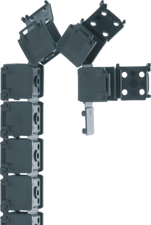
124 5.124 E1

125 System E1 E-Chain on 1 strip E1 Modular, 1-piece strip design for simple applications Very easy to assemble Various materials Snap open lids Economic solution for high volumes A universal and easily adaptable E-Chain concept E1: E-Chain on one strip Easy shortening/lengthening due to molded-on, modular strip Easy to snap-open Very cost effective, for high values Variable chain length - easy separation at each chain segment System E1 Strip connectors Easy fastening due to strip bore each link Various materials available You find more technical data about the material, chemical resistance, temperatures chapter design, from page 5.64 Opening-principle Dimensioning Bending radius Part No. structure Snap-open along outer radius Selection table Ba Bi hi ha R Bending radius E hi [mm] Bi [mm] Ba [mm] ha [mm] R [mm] [mm] Color black Radius Width Series Series Inner height Inner width Outer width Outer height Bending radius Length part Page E ,5 15, E E E E Additional quality features - System E1 Internet: info@igus.de UL94-V2 available upon request Next Page Find assembly instructions and application examples 5.125


126 E1 System E1 Applications igus E-ChainSystems E1: E-Chain modular, 1-piece strip designed for simple applications - The E1 design brings the benefits of an E-Chain to applications, where this solution previously was too expensive. E1 is more economic for higher volumes, quicker to assemble and still offers great control and protection for moving cables. The igus - System E1 is very cost effective for high volumes and is especially ideal for automotive applications. Typical industries and applications Automotive Office Solutions and technology Automation Electric equipment Machine-building Harnessed igus System E1 in a bottle deposit machine Series E in an electric wheelchair - cably supply on the scissors lifting system Internet: info@igus.de The igus -System E1 is very cost-effective at high quantities and ideal for automotive applications 5.126


127 System E1 Assembly Instructions E1 To shorten System E1 Internet: System E1 System E1 - E-Chain on one strip - easy to shorten... To lengthen System E1.. and to lengthen You can find an assembly video on the web

128 Economic, for high volumes - 3 sizes E System E1 Series E1.10 E1.17 E1.20 Price index R Easy shortening/lengthening due to molded-on, modular strip Easy to snap-open Variable chain length due to easy separation at each chain segment Strip connectors Easy fastening due to strip bore each link Low-price E-Chain Series E1 - snap-open along outer radius Part No. Bi [mm] Ba [mm] hi [mm] ha [mm] R[mm] A [mm] B [mm] E , , E ,5 255 E ,5 204 E ,5 255 E * igus E-ChainSystems Ba Bi * E Lids to open reciprocal Supplement Part No. with required radius. Example: E Bending radii listed above can be combined with every chain width! Ba Bi Ba Bi Part No. structure 9 max. Ø 4,5 hi ha 15 max. Ø 4,5 hi ha 18 max. Ø 4,5 hi ha E Black = standard color, other colors page 5.65 Bending radius Width-index hi Series E1.10 E1.17 E1.20 Order example 1,0 m complete E-Chain (indicate chain-lengths or number of strips) 1,0 m (4 strips) Series E (1 strip = 250 mm length) For detailed information on this igus product
129 System E1 Series E1.10 E1.17 E1.20 E1 Pitch = see Dim.A Length part = see Dim. B Chain length = S / 2 + K Installation Dimensions Bending radius for Series: E1.10 E1.17 E1.20 R H D K The required clearance height is H F = H + 40 mm More radii upon request! R S D S/2 A Moving end Fixed end ha H - ha H HF = H System E1 Inner height: 10, 17, 20 mm For detailed information on this igus product

130 5.130 SnapChain
![SnapChain Series TE14 TZ14 TE26 TZ26 SnapChain SnapChain Preisindex SnapChain - TE14 / TZ14 Part No. R [mm] Bending Radii TE14.50..0* 028 038 048 075 100 125 TZ14.50..0 028 038 048 075 100 125 Supplement Part No.](/docs-images/72/67718988/images/131-0.jpg "with required radius. Example: TE14.50. 100.0 Bending radii listed above can be combined with every chain width!")

131 SnapChain Series TE14 TZ14 TE26 TZ26 SnapChain SnapChain Preisindex SnapChain - TE14 / TZ14 Part No. R [mm] Bending Radii TE * TZ Supplement Part No. with required radius. Example: TE Bending radii listed above can be combined with every chain width! Fit cable assemblies quickly in bunches Adjust and change loops at any time Well-suited to short lengths, ideally 5-10 links Favorable alternative to complex hinged cable trays Version TE can be opened along outer radius - Version TZ along inner radius Can be bent in 1 or 2 directions Available in 2 sizes max. cable package 18 mm 55, ,5 SnapChain - TE26 / TZ26 Part No. R [mm] Bending Radii TE * TZ Supplement Part No. with required radius. Example: TE Bending radii listed above can be combined with every chain width! SnapChain - TE14 / TZ14 *Available as version RBR (reverse bending radius), Part No. TE14.50.Radius/Radius max. cable package 47 mm Applications Switch cubicle construction Electrical equipment Computer cubicles Office furniture Wherever cables are moved now and then Part No. structure TE Black = standard color, other colors page 5.65 Bending radius Width-index Series SnapChain - TE26 / TZ26 *Available as version RBR (reverse bending radius), Part No. TE Radius/Radius Order example 1,0 m complete E-Chain (indicate chain-lengths or number of links) 1,0 m (33 links) Series TE For detailed information on this igus product

132 System E2 E2/000 E2 mini E2 micro 5.132


133 System E2 micro, E2 mini and E2/000 Small and medium sizes E2 micro E2 mini E2/000 E2 micro E2 mini System E2 and E2/000 E2 micro from page For smallest inner heights One-piece E-Chains Space - saving ratio of inner-to-outer dimensions Inner heights 5-15 mm E2 mini from page Small and medium sizes Small pitch for smooth running One and two-piece E-Chains Inner heights mm System E2/000 from page E2 Standard - as E-Chain, "Half" E-Tube and fully enclosed E-Tube available E2/000 Snap-open mechanism - snap-open on left or right Lightning-fast closing with the touch of a thumb - secure fit without additional locking devices Excellent mechanical stability, long life due to design and material Inner heights mm Internet: info@igus.de For more information on specific igus E2 E-Chains use product link on each page 5.133
134 5.134 E2 micro

135 hi ha System E2 micro E-Chains for tight spaces E2 micro One-piece E-Chains Smallest inner heights Mounting brackets optional with strain relief Quicksnap and Quickfix available Small pitch for smooth running Cable-friendly, smooth interior Low weight Large pins for longer life Space-saving ratio of inner-to-outer dimensions You find more technical data about the material, chemical resistance, temperatures chapter design, from page 5.64 Cable-friendly, smooth interior High accelerations One piece each link System E2 micro Opening-principle Dimensioning Bending radius Only one-piece closed links available Selection table Ba Bi 03 5, ,7-13,7 8, , , ,0-35,0 10, , , ,0-70,0 12, , , ,0-68,0 12, , , ,5-71,0 15, , , ,2-58,2 19, , R Bending radius Part No. structure Color black Radius Width Series Series Inner height Inner width Outer width Outer height Bending radius Unsupported Page hi [mm] Bi [mm] Ba [mm] ha [mm] R [mm] length max. [m] Additional quality features - E2 micro UL94-V2 classifications for Series 03 and Series 04 (other upon request) IPA Certificate: Clean Room test upon request ESD-versions available upon request if-design awards - for E2 micro design - Series 05 5 mm Smallest inner heights 5 mm: Series 03 E2 micro Smallest inner heights and bending radii One-piece micro E-Chains with inner heights from 5 mm and bending radii from 10 mm for smallest spaces. Due to the lightweight design, the igus microseriesare also suitable for high speed applications. Internet: info@igus.de Next Page Find assembly instructions and application examples 5.135


136 E2 micro E2 micro Applications igus E-ChainSystems E2 micro are very small, one-piece, light-weight E-Chains ideal for high dynamic applications. E2 micro E-Chains are not openable and very cost effective and available in thousands of variations. igus also offers a host of accessories and fixation options. "Upgrades" to openable versions are available for many types. In these cases they are interchangeable and offer by this more service as repair kits or new installations. Typical industries and applications General machinery Models (Micro-Chains) Construction machinery Vehicles Furniture Electric cabinets General machinery - slow movements Electric equipment Vending machines Sliding door in train - UL 94-V2 version Smallest hight - For example Series 03: 5 mm inner height Internet: info@igus.de igus E2 micro E-Chains are robust for standing applications Sliding door in subway with igus Chainflex CF9 cable for smallest spaces 5.136


137 E2 micro Assembly Instructions E2 micro Assembling E2 micro 1 2 Separate E2 micro System E2 micro Twist and click Speciality E2 micro R Twist and separate igus micro E-Chains - for smallest bending radii with Chainflex CF98 and CF99-4 x d! For shorter assembly time... Minutes Reduce time up to 80% Minutes Reduce time up to 60% Product A Product A Easy Chain Easy Chain - Just push the cables with your thumb into the E-Chain - and it s ready from page 5.98 Zipper Zipper - Reduced assembly-time - Zipper-like design for quick opening and closing of lids from page 5.76 Internet: info@igus.de You can find an assembly video on the web
138 5 8 Smallest igus E-Chain 03 5 E2 micro Series 03 igus E-ChainSystems Fill weight [kg/m] Price index FL B FL G Unsupported length [m] Length of travel S [m] Unsupported length FL G = with straight upper run FL B = with permitted sag FLG HF H FLB 8 R Ba Bi 3,5 max. igus smallest E-Chain internal dimensions 5 x 5 Light weight and inexpensive Smallest bending radii Mounting bracket with integrated strain relief Dirt-repellent exterior Openable version: Easy Chain, page Series 03 - non snap-open Part No. Bi [mm] Ba [mm] R [mm] Bending Radii , , ,7 Radii for all widths! Supplement Part No. with required radius. Example: Bending radii listed above can be combined with every chain width! S (FLG) S (FLB) Part No. structure Black = standard color, other colors page 5.65 Bending radius Width-index Series Order example 1,0 m complete E-Chain (indicate chain-lengths or number of links) 1,0 m (100 links) Series set mounting brackets Z For detailed information on this igus product
139 E2 micro Series Pitch = 10 mm Links per m = 100 Chain length = S / 2 + K Installation Dimensions R H D K The required clearance height is H F = H + 5 mm (with 0,1 kg/m fill weight). Please consult igus if space is particularly restricted Z Z Moving end Z D S/2 Moving end 17 R Fixed end S 8 H-8 H Mounting Brackets 5 E2 micro Inner height: 5 mm B 3 Mounting bracket Adapter plate Part No QF For Part No. Dim. B E-Chain full set [mm] Z 8, Z 10, Z 13, Z Fixed end Polymer, one-piece - with integrated strain relief Full set, for both ends: Z Single-part order: Z Z (+ tiewrap plates) (+ tiewrap plates) Mounting bracket moving end (+ tiewrap plates) Mounting bracket fixed end QF = Adapter plate for all sizes - The adapter has broken edges, so that it can be adapted to the respective chain width. It is not absolutely necessary for attaching the mounting brackets. The mounting brackets can also be screwed on without the adapter plate. Adapter plate for rapid installation: Part No QF Additional Features For more features see link below For detailed information on this igus product
140 7 10 Very small 04 7 E2 micro Series 04 igus E-ChainSystems Fill weight [kg/m] Price index FL B FL G Unsupported length [m] 10 R Ba Bi Limited torsional motions possible Small E-Chain - internal dimensions 7 x 7 mm Light weight and inexpensive Dirt-repellent exterior Smallest bending radii Openable version: Easy Chain, Series 04 - non snap-open Part No. Bi [mm] Ba [mm] R [mm] Bending Radii Radii for all widths! Length of travel S [m] Unsupported length FL G = with straight upper run FL B = with permitted sag FLG HF H FLB 5 max. Supplement Part No. with required radius. Example: Bending radii listed above can be combined with every chain width! S (FLG) S (FLB) Part No. structure Black = standard color, other colors page 5.65 Bending radius Width-index Series Order example 1,0 m complete E-Chain (indicate chain-lengths or number of links) 1,0 m (60 links) Series set mounting brackets For detailed information on this igus product
141 E2 micro Series Pitch = 16,7 mm Links per m = 60 Chain length = S / 2 + K R H D K The required clearance height is H F = H + 5 mm (with 0,1 kg/m fill weight). Please consult igus if space is particularly restricted (PZ) (PZ) Moving end (PZ) D S/2 19 Moving end R Fixed end 16,7 21 S Installation Dimensions 10 H - 10 H Mounting Brackets 7 E2 micro Inner height: 7 mm 8 12,5 B B ø ø A PZ PZ PZ PZ PZ C C (PZ) Fixed end For Part No. Part No. Number Dim. A Dim. B Dim. C E-Chain full set with full set without of teeth [mm] [mm] [mm] tiewrap plate tiewrap plate Tiewrap plates are possible at the moving end and/or the fixed end! 20 One-piece, polymer pivoting with or without strain relief tiewrap plates Part No. structure PZ Full set, for both ends: PZ (+ tiewrap plates) Single-part order: Full set with tiewrap plate Full set without tiewrap plate PZ (+ tiewrap plates) Mounting bracket moving end PZ (+ tiewrap plates) Mounting bracket fixed end Additional Features Quicksnap - the complete, detachable mounting unit Quickfix - mounting bracket with dowel For more features see link below For detailed information on this igus product
142 10,3 12,5 Small pitch - smooth operation ,3 E2 micro Series 045 igus E-ChainSystems Fill weight [kg/m] Price index 0.25 FL B FL G Unsupported length [m] 12,5 R Ba Bi Small pitch for low-noise, smooth operation Smallest bending radii Dirt-repellent exterior Mounting bracket available Limited torsional motions possible Openable versions: Easy Chain, page Zipper, page 5.80 Series non snap-open Part No. Bi [mm] Ba [mm] R [mm] Bending Radii Radii for all widths! Length of travel S [m] Unsupported length FL G = with straight upper run FL B = with permitted sag FLG HF H FLB 8 max. Supplement Part No. with required radius. Example: Bending radii listed above can be combined with every chain width! S (FLG) S (FLB) Part No. structure Black = standard color, other colors page 5.65 Bending radius Width-index Series Order example 1,0 m complete E-Chain (indicate chain-lengths or number of links) 1,0 m (77 links) Series set mounting brackets For detailed information on this igus product
143 E2 micro Series Pitch = 13 mm Links per m = 77 Chain length = S / 2 + K R H D K The required clearance height is H F = H + 10 mm (with 0,2 kg/m fill weight). Please consult igus if space is particularly restricted (PZ) (PZ) ,25 18,25 4 Moving end (PZ) D S/2 Moving end R Fixed end 13 22,3 S Installation Dimensions 12,5 H = 12,5 H Mounting Brackets 10,3 E2 micro Inner height: 10,3 mm B B 8 ø PZ PZ PZ PZ PZ PZ / ,25 18,25 4 ø 3 A 6/90 C C (PZ ) Fixed end For Part No. Part No. Number Dim. A Dim. B Dim. C E-Chain full set with full set without of teeth [mm] [mm] [mm] tiewrap plate tiewrap plate Tiewrap plates are possible at the moving end and/or the fixed end! The mounting brackets are available upon request. Time of delivery approx. 6-8 weeks after order. One-piece, polymer pivoting with or without strain relief tiewrap plates Part No. structure PZ Full set, for both ends: Single-part order: Full set with tiewrap plate Full set without tiewrap plate 12 PZ (+ tiewrap plates) 1 PZ (+ tiewrap plates) Mounting bracket moving end 2 PZ (+ tiewrap plates) Mounting bracket fixed end Additional Features Series 046 with full-width shelving upon request Quicksnap - the complete, detachable mounting unit Quickfix - mounting bracket with dowel For more features see link below For detailed information on this igus product
144 10 12 Classic size E2 micro Series 05 igus E-ChainSystems Fill weight [kg/m] Price index FL B 0.25 FL G Unsupported length [m] Length of travel S [m] Unsupported length FL G = with straight upper run FL B = with permitted sag FLG HF H FLB 12 R Ba Bi 8 max. Very light weight - ideal for low fill weight Small pitch for low-noise, smooth operation Mounting bracket available if-design Award Winner Series 05 - non snap-open Part No. Bi [mm] Ba [mm] R [mm] Bending Radii Radii for all widths! Supplement Part No. with required radius. Example: Bending radii listed above can be combined with every chain width! S (FLG) S (FLB) Part No. structure Black = standard color, other colors page 5.65 Bending radius Width-index Series Order example 1,0 m complete E-Chain (indicate chain-lengths or number of links) 1,0 m (50 links) Series set mounting brackets For detailed information on this igus product
145 E2 micro Series Pitch = 20 mm Links per m = 50 Chain length = S / 2 + K R H D K The required clearance height is H F = H + 10 mm (with 0,2 kg/m fill weight). Please consult igus if space is particularly restricted D R Moving end S S/2 Installation Dimensions Moving end Fixed end H - 12 H Mounting Brackets 10 E2 micro Inner height: 10 mm B A 3 t = 1 t = : Center bores only : Outer bores only For Part No. Dim. A Dim. B E-Chain full set [mm] [mm] , , , , , ,7 A B Fixed end Standard - one-piece, polymer, pivoting Full set, for both ends: Single-part order: Mounting bracket moving end Mounting bracket fixed end Additional Features Quicksnap - the complete, detachable mounting unit Quickfix - mounting bracket with dowel For more features see link below For detailed information on this igus product
146 10,5 15 Classic size - strong version 06 10,5 E2 micro Series 06 igus E-ChainSystems Fill weight [kg/m] Price index FL B 0.25 FL G Unsupported length [m] Length of travel S [m] 15 R Ba Bi High torsional rigidity Light weight and inexpensive Small bending radii Dirt-repellent exterior Mounting bracket with integrated strain relief Openable version: Easy Chain, Molded-in separator available Series S1 Series 06 - non snap-open Part No. Bi [mm] Ba [mm] R [mm] Bending Radii , , , , , , , ,0 Radii for all widths! Unsupported length FL G = with straight upper run FL B = with permitted sag FLG HF H FLB 8 max. Supplement Part No. with required radius. Example: Bending radii listed above can be combined with every chain width! S (FLG) S (FLB) Part No. structure Black = standard color, other colors page 5.65 Bending radius Width-index Series Order example 1,0 m complete E-Chain (indicate chain-lengths or number of links) 1,0 m (50 links) Series set mounting brackets + tiewrap plate PZ For detailed information on this igus product
147 E2 micro Series Pitch = 20 mm Links per m = 50 Chain length = S / 2 + K Installation Dimensions R H D K The required clearance height is H F = H + 10 mm (with 0,2 kg/m fill weight). Please consult igus if space is particularly restricted (PZ) (PZ) Moving end (PZ) S D S/2 Moving end Fixed end R H - 15 H Mounting Brackets 10,5 E2 micro Inner height: 10,5 mm B 5,8/90 5,8/90 3,2 A A : Center bores only : Outer bores only For Part No. Part No. Number Dim. A Dim. B E-Chain full set with full set without of teeth [mm] [mm] tiewrap plate PZ , PZ , PZ , PZ , PZ , PZ , PZ , PZ ,0 3,2 tiewrap plate Tiewrap plates are possible at the moving end and/or the fixed end! B (PZ) Fixed end One-piece, polymer pivoting with or without strain relief tiewrap plates Part No. structure PZ Full set, for both ends: PZ (+ tiewrap plates) Single-part order: Full set with tiewrap plate Full set without tiewrap plate PZ (+ tiewrap plates) Mounting bracket moving end PZ (+ tiewrap plates) Mounting bracket fixed end Additional Features Quicksnap - the complete, detachable mounting unit Quickfix - mounting bracket with dowel For more features see link below Molded-in separator - Line-extension Part No S1 - Separated into 2 compartments: 8,5 mm, 6,3 mm, Bending radius 18 mm. Safe cable separation in small dimensions For detailed information on this igus product
148 15 19,3 Allrounder E2 micro Series 08 igus E-ChainSystems Charge supplémentaire [kg/m] Price index FL B 0.5 FL G Unsupported length [m] Length of travel S [m] 19,3 R Ba Bi Small pitch for low-noise, smooth operation High torsional rigidity Small bending radii Mounting bracket with integrated strain relief Dirt-repellent exterior Openable versions: Easy Chain, page Zipper, page 5.84 Series 08 - non snap-open Part No. Bi [mm] Ba [mm] R [mm] Bending Radii ,2 025* ,2 048** , , , , ,2 Radii for all widths! 025* only for ** not for Unsupported length FL G = with straight upper run FL B = with permitted sag FLG HF H FLB 12 max. Supplement Part No. with required radius. Example: Bending radii listed above can be combined with every chain width! S (FLG) S (FLB) Part No. structure Black = standard color, other colors page 5.65 Bending radius Width-index Series Order example 2,0 m complete E-Chain (indicate chain-lengths or number of links) 2,0 m (100 links) Series set mounting brackets + tiewrap plate PZ For detailed information on this igus product
149 E2 micro Series Pitch = 20 mm Links per m = 50 Chain length = S / 2 + K R 025* ** H D K The required clearance height is H F = H + 15 mm (with 0,3 kg/m fill weight). Please consult igus if space is particularly restricted. *025 only for Part No ** not for (PZ) (PZ) D R +3 Moving end (PZ) Installation Dimensions S S/2 Moving end Fixed end ,3 H - 19,3 H Mounting Brackets 15 E2 micro Inner height: 15 mm 2 B 5,8/90 3,2 A A : Center bores only : All bores 5,8/90 For Part No. Part No. Number Dim. A Dim. B E-Chain full set with full set without of teeth [mm] [mm] tiewrap plate PZ , PZ , PZ , PZ , PZ , PZ , PZ ,2 3,2 tiewrap plate Tiewrap plates are possible at the moving end and/or the fixed end! B (PZ) Fixed end One-piece, polymer pivoting with or without strain relief tiewrap plates Part No. structure PZ Full set, for both ends: Full set with tiewrap plate Full set without tiewrap plate PZ (+ tiewrap plates) Single-part order: PZ (+ tiewrap plates) Mounting bracket moving end PZ (+ tiewrap plates) Mounting bracket fixed end Additional Features Quicksnap - the complete, detachable mounting unit Quickfix - mounting bracket with dowel For more features see link below For detailed information on this igus product

150 5.150 E2 mini

151 hi ha System E2 mini Small and medium sizes E2 mini E2 mini - one/two-piece E-Chains - small and medium sizes Large Pins Double stop dog Cable-friendly, smooth interior Material igumid G -40/+120 C Small pitch for smooth running Double stop dock for long service life Optimized relation: weight - stability Large pins for long unsupported lengths Easy to assemble Various interior separation You find more technical data about the material, chemical resistance, temperatures chapter design, from page 5.64 System E2 mini Opening-principle Dimensioning Bending radius B15i B15 B17 Snap-open links are not necessary Snap-open along inner radius Snap-open along outer radius Selection table Ba Bi , , B15i / B a 1, B , , F , R Bending radius Part No. structure Color black Radius Width Series Series Inner height Inner width Outer width Outer height Bending radius Unsupported Page hi [mm] Bi [mm] Ba [mm] ha [mm] R [mm] length max. [m] Additional quality features - E2 mini UL94-V2 classifications - Series 14 Cleanroom Class 1 (ISO class 3) for Series 10 and 14, tested by the Dryden Engineering Company, California ESD-version available upon request - for Series 10 For shorter assembly time... Minutes Reduce time up to 80% Minutes Reduce time up to 60% Product A Easy Chain Easy Chain Series 200 Easy Chain - Just push the cables with your thumb into the E-Chain - and it s ready from page 5.98 Zipper Product A Zipper Series R17 Zipper - Reduced assembly-time - Zipper-like design for quick opening and closing of lids from page 5.76 Internet: info@igus.de Next Page Find assembly instructions and application examples 5.151


152 E2 mini System E2 mini Applications igus E-ChainSystems E2 mini are small one-piece or two-piece E-Chains ideal for high dynamic applications. igus also offers a host of accessoirs and fixation options. "Upgrades" to openable versions are available for many types in these cases they are interchangeable and can also serve as replacement. Typical industries and applications General machinery Models (Micro-Chains) Construction machinery Vehicles Furniture Electric cabinets General machinery - slow movements Electric equipment Vending machines Short travels and high accelerations with Series E2 mini in a handling machine Openable E-Chains with high stability igus E2 mini - Series B15 Internet: info@igus.de E2 mini in a milling machine with hot chips and chemials - UL94-V2 version Long-travel applications up to 40 m are possible - here in textile machine 5.152


153 System E2 mini Assembly Instructions E2 mini Assembling E2 mini 1 2 System E2 mini Push and click Snap in pin 3 Push and snap Separation E2 mini 1 2 Lever crossbars open 3 Swivel crossbars 4 Release side-link Twist and pull apart Internet: info@igus.de You can find an assembly video on the web
![18 23 Large pins and double stop dog 10 18 E2 mini Series 10 igus E-ChainSystems Fill weight [kg/m] 2.0 1.5 1.0 0.5 FL G FL B 0 0 0.5 1.0 1.5 2.0 Unsupported length [m] HF 0 1.0 2.0 3.0 4.](/docs-images/72/67718988/images/154-0.jpg "0 H Price index Length of travel S [m] Unsupported length FL G = with straight upper run FL B = with permitted sag FLG FLB 23 R 16 max.")
154 18 23 Large pins and double stop dog E2 mini Series 10 igus E-ChainSystems Fill weight [kg/m] FL G FL B Unsupported length [m] HF H Price index Length of travel S [m] Unsupported length FL G = with straight upper run FL B = with permitted sag FLG FLB 23 R 16 max. Ba Bi Larger pins and double stop dog for long service life and long unsupported length Mounting bracket with integrated strain relief Dirt-repellent exterior Snap-open links are not necessary Small but very stable E-Chain Interior Separation possible Custom-made E-Chains with reverse bending radius "RBR" available for circular movements Molded-in separator available Series S Series 10 - non snap-open Part No. Bi [mm] Ba [mm] R [mm] Bending Radii Radii for all widths! Supplement Part No. with required radius. Example: Bending radii listed above can be combined with every chain width! S (FLG) S (FLB) Part No. structure Black = standard color, other colors page 5.65 Bending radius Width-index Series Order example 2,0 m complete E-Chain (indicate chain-lengths or number of links) 2,0 m (66 links) Series separators 111 assembled every 2 nd link + 1 set mounting brackets + tiewrap plate PZ Molded-in separator - Line-extension Part No Inner/outer width 50/61 mm, radius 75 mm, more sizes upon request Separation: Middle compartment 21 mm, 2 side compartments 13 mm For detailed information on this igus product
155 E2 mini Series Pitch = 30,5 mm Links per m = 33 Chain length = S / 2 + K Installation Dimensions D S/2 R H D Moving end K R Fixed end The required clearance height is H F = H + 20 mm (with 1,5 kg/m fill weight). Please consult igus if space is particularly restricted. 30,5 38 1,5 Vertical separator unassembled 101 assembled P(Z) P(Z) Moving end 17 7, ,5 16,5 14 7, P(Z) , One-piece, polymer B A A 11 B S 23 H - 23 H Interior Separation Mounting Brackets P(Z) P(Z) P(Z) pivoting with or without Fixed end strain relief tiewrap plates 18 E2 mini Inner height: 18 mm B A A 6,2 B P(Z) P(Z) For Part No. Part No. Dim. A Dim. B E-Chain full set with full set without [mm] [mm] tiewrap plate tiewrap plate PZ P 25, PZ P 10 35, PZ P 23 48, PZ P 35 60, PZ P 48 75, PZ P 65 92, PZ P ,0 Tiewrap plates are possible at the moving end and/or the fixed end! Part No. structure P Z Full set, for both ends: PZ PZ Full set with tiewrap plate Full set without tiewrap plate PZ (+ tiewrap plates) Single-part order: (+ tiewrap plates) Mounting bracket moving end (+ tiewrap plates) Mounting bracket fixed end Additional Features Polymer locking with or without strain relief tiewrap plates Quicksnap - the complete, detachable mounting unit Quickfix - mounting bracket with dowel For more features see link below For detailed information on this igus product
![20 25 Snap-open along inner radius 14 20 E2 mini Series 14 igus E-ChainSystems Fill weight [kg/m] Price index 1.50 1.25 1.](/docs-images/72/67718988/images/156-1.jpg "00 0.75 0.50 FL B 0.25 FL G 0 0 0.25 0.50 0.75 1.00 1.25 1.")
156 20 25 Snap-open along inner radius E2 mini Series 14 igus E-ChainSystems Fill weight [kg/m] Price index FL B 0.25 FL G Unsupported length [m] 25 R Ba Bi Snap-open along inner radius with film-hinge UL94-V2 flammability rating Mounting bracket with integrated strain relief Dirt-repellent exterior Series 14 - snap-open along inner radius Part No. Bi [mm] Ba [mm] R [mm] Bending Radii Radii for all widths! Length of travel S [m] Unsupported length FL G = with straight upper run FL B = with permitted sag FLG HF H FLB 16 max. Supplement Part No. with required radius. Example: Bending radii listed above can be combined with every chain width! S (FLG) S (FLB) Part No. structure Black = standard color, other colors page 5.65 Bending radius Width-index Series Short travel lenghts and high accelerations with Series 14 Order example 2,0 m complete E-Chain (indicate chain-lengths or number of links) 2,0 m (66 links) Series set mounting brackets + tiewrap plate PZ For detailed information on this igus product
157 E2 mini Series Pitch = 30,5 mm Links per m = 33 Chain length = S / 2 + K Installation Dimensions D S/2 R H D Moving end K R Fixed end The required clearance height is H F = H + 20 mm (with 0,5 kg/m fill weight). Please consult igus if space is particularly restricted. 30, P(Z) P(Z) Moving end P(Z) 90 S 25 H - 25 H Mounting Brackets 20 E2 mini Inner height: 20 mm B 6,5 A P(Z) P(Z) A 4 For Part No. Part No. Dim. A Dim. B E-Chain full set with full set without [mm] [mm] tiewrap plate tiewrap plate PZ P 26, PZ P 10 36, PZ P 23 49, PZ P 35 61,3 Tiewrap plates are possible at the moving end and/or the fixed end! B P(Z) Fixed end One-piece, polymer pivoting with or without strain relief tiewrap plates Part No. structure P Z Full set, for both ends: Full set with tiewrap plate Full set without tiewrap plate PZ (+ tiewrap plates) Single-part order: PZ (+ tiewrap plates) Mounting bracket moving end PZ (+ tiewrap plates) Mounting bracket fixed end Additional Features Quicksnap - the complete, detachable mounting unit Quickfix - mounting bracket with dowel For more features see link below For detailed information on this igus product
![23 17,5 17,5 23 B15i B15 Snap-open along inner and outer radius E2 mini Series B15i B15 17 17 igus E-ChainSystems Fill weight [kg/m] 2.0 1.5 1.0 0.5 FL G FL B 0 0 0.5 1.0 1.5 2.0 Unsupported length [m] HF Part No.](/docs-images/72/67718988/images/158-0.jpg "structure 0 1.0 2.0 3.0 4.0 H S (FLG) S (FLB) Price index Length of travel S [m] Unsupported length FL G = with straight upper run FL B = with permitted sag FLG FLB 23 14 max.")
158 23 17,5 17,5 23 B15i B15 Snap-open along inner and outer radius E2 mini Series B15i B igus E-ChainSystems Fill weight [kg/m] FL G FL B Unsupported length [m] HF Part No. structure H S (FLG) S (FLB) Price index Length of travel S [m] Unsupported length FL G = with straight upper run FL B = with permitted sag FLG FLB max. R R Ba Bi Ba Bi Larger pins and double stop dog for long service life and long unsupported length Snap-open along outer (B15) and inner (B15i) radius Mounting bracket with integrated strain relief Dirt-repellent exterior Small but very stable E-Chain Custom-made E-Chains with reverse bending radius "RBR" available for circular movements Series B15i - snap-open along inner radius Part No. Bi [mm] Ba [mm] R [mm] Bending Radii B15i B15i B15i B15i B15i B15i B15i Bi [mm] Ba [mm] R [mm] Bending Radii B B B B B B B Radii for all widths! Supplement Part No. with required radius. Example: B15i Bending radii listed above can be combined with every chain width! Series B15 - snap-open along outer radius Part No. Radii for all widths! B Black = standard color, other colors page 5.65 Bending radius Width-index Series 14 max. Supplement Part No. with required radius. Example: B Bending radii listed above can be combined with every chain width! Order example 3,0 m complete E-Chain (indicate chain-lengths or number of links) 3,0 m (99 links) Series B separators 154 assembled every 2 nd link + 1 set mounting brackets + tiewrap plate PZ For detailed information on this igus product
159 E2 mini Series B15i B15 B15i B15 Pitch = 30,5 mm Links per m = 33 Chain length = S / 2 + K Installation Dimensions R H D K The required clearance height is H F = H + 20 mm (with 1,5 kg/m fill weight). Please consult igus if space is particularly restricted P(Z) P(Z) 17 7, ,5 16,5 14 7,5 6,5 B A A 11 B S D S/2 Moving end R Fixed end 30,5 38 Vertical separator, 1,5 slotted unassembled 153 assembled Moving end 23 H - 23 H Interior Separation Mounting Brackets P(Z) Standard polymer, pivoting P(Z) P(Z) P(Z) with or without strain Fixed end relief tiewrap plates E2 mini Inner height: 17 mm B A A 6,2 B P(Z) P(Z) For Part No. Part No. Dim. A Dim. B E-Chain full set with full set without [mm] [mm] tiewrap plate tiewrap plate B15i B PZ P 25,5 B15i B PZ P 10 35,5 B15i B PZ P 23 48,5 B15i B PZ P 35 60,5 B15i B PZ P 48 75,0 B15i B PZ P 65 92,0 B15i B PZ P ,0 Tiewrap plates are possible at the moving end and/or the fixed end! Part No. structure P Z Full set, for both ends: PZ PZ Full set with tiewrap plate Full set without tiewrap plate PZ (+ tiewrap plates) Single-part order: (+ tiewrap plates) Mounting bracket moving end (+ tiewrap plates) Mounting bracket fixed end Additional Features Interior separation with full-width shelves Quicksnap - the complete, detachable mounting unit Quickfix - mounting bracket with dowel For more features see link below For detailed information on this igus product
160 39 32 Snap-open with film-hinge B17 32 E2 mini Series B17 igus E-ChainSystems Fill weight [kg/m] FL B 0.50 FL G Unsupported length [m] Length of travel S [m] Unsupported length FL G = with straight upper run FL B = with permitted sag FLG HF H Price index FLB 39 R 28 max. Bi Ba Snap-open with film-hinge Small pitch for low-noise, smooth operation Mounting bracket with integrated strain relief Dirt-repellent exterior Rather small chain with broad inner width Custom-made E-Chains with reverse bending radius "RBR" available for circular movements Series B17 - snap-open along outer radius Part No. Bi [mm] Ba [mm] R [mm] Bending Radii B ,5 048* B , B ,5 B ,5 B ,0 B ,0 B ,0 Radii for all widths! *Radius 048 not for B17.5 and B17.7 Supplement Part No. with required radius. Example: B Bending radii listed above can be combined with every chain width! S (FLG) S (FLB) Part No. structure B Black = standard color, other colors page 5.65 Bending radius Width-index Series Order example 3,0 m complete E-Chain (indicate chain-lengths or number of links) 3,0 m (99 links) Series B separators 172B assembled every 2 nd link + 1 set mounting brackets + tiewrap plate PZ Chip protection Fully enclosed E-Tube with zipper opening mechanism Protection against dirt and chips Superfast opening of interconnected lids Modular design - tool-free lengthening and shortening Small pitch for low noise, smooth operation, high acceleration Zipper E-Tube R17, inner height 32 mm from page For detailed information on this igus product
161 E2 mini Series B17 B17 Pitch = 30,5 mm Links per m = 33 Chain length = S / 2 + K R 048* H D K The required clearance height is H F = H + 25 mm (with 1,5 kg/m fill weight). Please consult igus if space is particularly restricted. * Radius 048 not for B17.5 and B B 172B P(Z) P(Z) /90 10/90 B A A B 5,2 5, P(Z): Center bores only P(Z) P(Z): Outer bores only S D S/2 Moving end R Fixed end 30,5 38 Installation Dimensions 39 H - 39 H Interior Separation Vertical separator 2 for B17.1 to B17.4 unassembled 171B assembled 172B 10 Vertical separator 1,5 for B17.5 to B17.7 unassembled 173B assembled 174B 10 Moving end Mounting Brackets P(Z) Standard - one-piece, polymer P(Z) locking with or without Fixed end strain relief tiewrap plates Part No. structure 32 E2 mini Inner height: 32 mm For Part No. Part No. Number Dim. A Dim. B E-Chain full set with full set without of teeth [mm] [mm] tiewrap plate tiewrap plate B PZ P 2 25,5 B PZ P ,5 B PZ P ,5 B PZ P ,5 B PZ P ,0 B PZ P ,0 B PZ P ,0 Tiewrap plates are possible at the moving end and/or the fixed end! P Z Full set, for both ends: PZ (+ tiewrap plates) Single-part order: Full set with tiewrap plate Full set without tiewrap plate PZ (+ tiewrap plates) Mounting bracket moving end PZ (+ tiewrap plates) Mounting bracket fixed end Additional Features Interior separation with full-width shelves For more features see link below For detailed information on this igus product
![32 39 F17 Snap-open along inner radius - closed outside E2 mini Series F17 32 igus E-ChainSystems Fill weight [kg/m] 2.0 1.5 1.0 0.5 FL G Price index FL B 0 0 0.5 1.0 1.5 2.](/docs-images/72/67718988/images/162-0.jpg "0 39 Ba Bi R Snap-open along inner radius with film-hinge Small pitch for smooth running Mounting bracket with integrated strain relief Dirt-repellent exterior One-piece, small E-Chain with great")
162 32 39 F17 Snap-open along inner radius - closed outside E2 mini Series F17 32 igus E-ChainSystems Fill weight [kg/m] FL G Price index FL B Ba Bi R Snap-open along inner radius with film-hinge Small pitch for smooth running Mounting bracket with integrated strain relief Dirt-repellent exterior One-piece, small E-Chain with great inner height Small Bending radii Elegant design Closed outside Series F17 - snap-open along inner radius Part No. Bi [mm] Ba [mm] R [mm] Bending Radii F The bending radii 063, 075, 100, 125 are available upon request. Delivery time: approx weeks after receipt of order! HF Unsupported length [m] Length of travel S [m] Unsupported length FL G = with straight upper run FL B = with permitted sag H FLG FLB 28 max. Supplement Part No. with required radius. Example: F Bending radii listed above can be combined with every chain width! S (FLG) S (FLB) Part No. structure F Black = standard color, other colors page 5.65 Bending radius Width-index Series Order example 1,0 m complete E-Chain (indicate chain-lengths or number of links) 1,0 m (33 links) Series F separators R172 assembled every 2 nd link + set mounting brackets PZ For detailed information on this igus product
163 E2 mini Series F17 F17 Pitch = 30,5 mm Links per m = 33 Chain length = S / 2 + K R 048 H 135 D 100 K 220 The required clearance height is H F = H + 30 mm (with 0,5 kg/m fill weight). Please consult igus if space is particularly restricted. R P(Z) P(Z) , , B A B D S/2 Moving end R Fixed end 30,5 38 S Installation Dimensions 39 H - 39 H Interior Separation Vertical separator 1,5 slotted unassembled R171 assembled R172 8 Moving end Mounting Brackets P(Z ) Standard polymer, pivoting P(Z) with or without strain Fixed end relief tiewrap plates 32 E2 mini Inner height: 32 mm Part No. structure For Part No. Part No. Number Dim. A Dim. B E-Chain full set with full set without of teeth [mm] [mm] tiewrap plate tiewrap plate F PZ P 2 25,7 Tiewrap plates are possible at the moving end and/or the fixed end! P Z Full set, for both ends: Single-part order: Full set with tiewrap plate Full set without tiewrap plate 12 PZ (+ tiewrap plates) 1 PZ (+ tiewrap plates) Mounting bracket moving end 2 PZ (+ tiewrap plates) Mounting bracket fixed end Additional Features Interior separation with full-width shelves For more features see link below For detailed information on this igus product

164 E2/


165 hi ha hi ha E2/000 E-Chains E-Tubes The E2 standard! E2/000 E2/000 E-Chains - the standard for System E2 Open crossbar left or right quickly with scredriver or by hand Opening mechanism accessible from above to allow access in confined spaces Lightning-fast closing by hand - Secure fit without additional locking devices Secure fit of interior separation even when E-Chain is open Excellent mechanical stability, long life due to design and material You can find more technical data about the material, chemical resistance, temperatures chapter design, from page 5.64 Large pin for longer unsupported length Double stop dog Opening system from left or right Lateral glide surfaces E2/000 medium Opening-principle Dimensioning Bending radius Snap-open along outer radius on left or right side Snap-open along inner radius on left or right side Selection table Ba Bi 1400/ ,5-138, , / ,0-141, , / ,0-194, , / ,0-245, , ,0-119, , Two-piece half- and fully enclosed E-Tube Enclosed E-Tube can be used in chip areas (also hot chips) Snap-open mechanism, snap-open on left or right Opening mechanism accessible from above - rapid opening of the E-Tube with a screwdriver or by hand Lightning-fast closing by hand - Secure fit without additional locking devices Secure fit of interior separation even when E-Tube is open You can find more technical data about the material, chemical resistance, temperatures chapter design, from page 5.64 Ba Bi R Series Inner height Inner width Outer width Outer height Bending radius Unsupported Page hi [mm] Bi [mm] Ba [mm] ha [mm] R [mm] length max. [m] 1450/ ,5-138, , / ,0-119, , / ,0-141, , / ,0-245, , Additional quality features - E2/000 Next Page R Bending radius Material igumid Double ESD upon request stop dog Opening-principle Dimensioning Bending radius Snap-open along inner radius on left or right side (for all full and half E-Tubes) Selection table Find assembly instructions and application examples Opening system for rapid opening Color black Radius Width Series Lateral glide surfaces Color black Radius Width Series Series Inner height Inner width Outer width Outer height Bending radius Unsupported Page hi [mm] Bi [mm] Ba [mm] ha [mm] R [mm] length max. [m] IPA Qualification Certificate Air Cleanless Class ISO Class 3 (at v = 2 m/s) Bending radius Part No. structure Part No. structure ESD classification ISO class 5 (v = 1 m/s) Series with standard material igumid G - Special equipment: Electrically conductive ESD/ATEX version upon request Internet: info@igus.de 5.165


166 E2/000 System E2/000 Applications igus E-ChainSystems E2/000: E-Chains with a 2-piece link design - The E2/000 Series is igus fourth generation in this popular size range. All the experience went into this "New Millenium Series": easy and versatile assembly combined with ruggedness - high stability paired with quieter motion; long cable life parallel with many fixation options. The design is consistent within all E2/000 variations. It is the trusted program of machine builders around the world. Typical industries and applications General machinery Material Handling Construction machinery Long travel applications in many industries Semicon ESD Atex versions certified Theatrical and Entertainment and Amusement parcs Vehicles And many more 977 igus E-Chains of the Series 2400 are used for a special stage equipment Special snap-open mechanism, choice of snap-open on left or right. Hinged crossbar can be swiveled by more than 180 on both sides Internet: info@igus.de Hanging application with Series 2400 Side mounted application with Series


167 System E2/000 Assembly Instructions E2/000 Assembling E2/ Push and click Snap in pin Swivel crossbars E2/000 medium Push and snap Snap mounting bracket into link Snap tiewrap plate into bottom groove Separation E2/ Lever crossbars open Release side-link Twist and pull apart Opening Closing E2/000 E-Tube Open: swivel lids Close: push and snap Half E-Tube: swivel crossbars 4 5 Lever Remove lid You can find an assembly video on the web Internet: info@igus.de 5.167
168 Small and strong E2/000 E-Chains Series igus E-ChainSystems Fill weight [kg/m] FL B FL G Unsupported length [m] HF Part No. structure H S (FLG) S (FLB) Price index Length of travel S [m] Unsupported length FL G = with straight upper run FL B = with permitted sag FLG FLB Black = standard color, other colors page 5.65 Bending radius Width-index Series Order example 2,0 m complete E-Chain (indicate chain-lengths or number of links) 2,0 m (60 links) Series separators assembled every 2 nd link + 1 set mounting brackets PZ half E-Tube and fully enclosed E-Tube next page R Ba Bi 18 max. R 18 max. Bi Ba Opening system for rapid opening, either from the right or the left Double stop dog and large pins for longer unsupported lengths Crossbars with high locking range Integrated strain relief possible Secure fit of separators and interior separation even when E-Chain is open Custom-made E-Chains with reverse bending radius "RBR" available for circular movements Series snap-open along inner radius Part No. Bi [mm] Ba [mm] R [mm] Bending Radii , , , , , , , , ,5 Bi [mm] Ba [mm] R [mm] Bending Radii , , , , , , , , ,5 Radii for all widths! Supplement Part No. with required radius. Example: Bending radii listed above can be combined with every chain width! Series snap-open along outer radius Part No. Radii for all widths! The width Bi 20 is available upon request. Delivery time: approx. 6-8 weeks after receipt of order! Supplement Part No. with required radius. Example: Bending radii listed above can be combined with every chain width! For detailed information on this igus product
169 E2/000 E-Chains Series Pitch = 33,3 mm Links per m = 30 Chain length = S / 2 + K R H D K The required clearance height is H F = H + 25 mm (with 0,5 kg/m fill weight). Please consult igus if space is particularly restricted PZ PZ 53, ,5 S D S/2 R Moving end PZ Installation Dimensions Moving end Fixed end H - 28 H Mounting Brackets 21 8 E2/000 medium Inner height: 21 mm ,5 A / PZ 28, / PZ 33, / PZ 13 38, / PZ 24 51, / PZ 36 63, / PZ 54 81, / PZ 66 93, / PZ , / PZ , ,5 B B For Part No. Dim.A Dim.B Number E-Chain : full set with [mm] [mm] of teeth tiewrap plate Tiewrap plates are possible at the moving end and/or the fixed end! PZ Fixed end One-piece, polymer, pivoting Full set, for both ends: PZ (+ tiewrap plates) Single-part order: PZ (+ tiewrap plates) Mounting bracket moving end PZ (+ tiewrap plates) Mounting bracket fixed end Additional Features Interior Separation page One-piece mounting brackets - locking Mounting bracket - polymer Mounting bracket steel For more features see link below For detailed information on this igus product
170 Small and strong, closed design E2/000 E-Tubes Series igus E-ChainSystems Fill weight [kg/m] FL B FL G Unsupported length [m] HF Part No. structure H S (FLG) S (FLB) Price index Length of travel S [m] Unsupported length FL G = with straight upper run FL B = with permitted sag FLG FLB Black = standard color, other colors page 5.65 Bending radius Width-index Series Order example 2,0 m complete E-Tube (indicate tube-lengths or number of links) 2,0 m (60 links) Series separators assembled every 2 nd link + 1 set mounting brackets PZ 28 R Ba Bi 18 max. R Ba Bi 18 max Opening system for rapid opening, either from the right or the left Double stop dog and large pins for longer unsupported lengths Crossbars/lids with high locking range Tried-and-tested firmly-locked mounting bracket Protection against dust, dirt and chips (also hot chips) Series 1450 half E-Tube - snap-open along inner radius Part No. Bi [mm] Ba [mm] R [mm] Bending Radii , , , , , , , ,5 Bi [mm] Ba [mm] R [mm] Bending Radii , , , , , , , ,5 Radii for all widths! The bending radii 035, 038, 048 are available upon request. Delivery time: approx. 6-8 weeks after receipt of order! Supplement Part No. with required radius. Example: Bending radii listed above can be combined with every tube width! Series 1480 fully enclosed E-Tube - snap-open along inner radius Part No E-Chains previous page Radii for all widths! The bending radii 035, 038, 048 are available upon request. Delivery time: approx. 6-8 weeks after receipt of order! Supplement Part No. with required radius. Example: Bending radii listed above can be combined with every tube width! For detailed information on this igus product
171 E2/000 E-Tubes Series Pitch = 33,3 mm Links per m = 30 Chain length = S / 2 + K Installation Dimensions R H D K The required clearance height is H F = H + 25 mm (with 0,5 kg/m fill weight). Please consult igus if space is particularly restricted. The bending radii 035, 038, 048 are available upon request PZ PZ S D S/2 R Moving end PZ 53, , Moving end Fixed end H - 28 H Mounting Brackets 21 E2/000 medium Inner height: 21 mm ,5 A PZ 28, PZ 13 38, / PZ 24 51, / PZ 36 63, PZ 54 81, PZ 66 93, PZ , PZ , ,5 B B For Part No. Dim.A Dim.B Number E-Chain : full set with [mm] [mm] of teeth tiewrap plate Tiewrap plates are possible at the moving end and/or the fixed end! PZ Fixed end One-piece, polymer, pivoting Full set, for both ends: PZ (+ tiewrap plates) Single-part order: PZ (+ tiewrap plates) Mounting bracket moving end PZ (+ tiewrap plates) Mounting bracket fixed end Additional Features nterior Separation page One-piece mounting brackets - locking Mounting bracket - polymer Mounting bracket steel For more features see link below For detailed information on this igus product
172 igus E-ChainSystems 1,5 Vert. Separator, slotted 5 unassembled assembled E2/000 Series Interior Separation Option 1: Vertical Separators for E-Chains Series Vertical Separators are used if a vertical subdivision of the E-Chain interior is required - By standard Vertical Separators are assembled every other E-Chain link Standard subdivision with Vertical Separator, slotted 14011, for combinations with Full-Width Shelf 111.X ,5 Vert. Separator, slotted 5 unassembled assembled Option 2: Vertical Separators for E-Tubes Series Vertical Separators are used if a vertical subdivision of the half E-Tube (Series 1450) and the fully enclosed E-Tube (Series 1480) interior is required - By standard Vertical Separators are assembled every other E-Chain link Standard subdivision with Vertical Separator, slotted 14511, for combinations with Full-Width Shelf 111.X Option 3: Full-Width Shelves for E-Chains Series and E-Tubes Series For applications involving many cables with similar or identical diameters Full-Width Shelf 111.X can be combined with Vertical Separator, slotted (E-Chain ) and Vertical Separator, slotted (E-Tube/half E-Tube) 5,75 2 5, X Width Part No. Part No. Width Part No. Part No. X [mm] unassembled assembled X [mm] unassembled assembled Internet: info@igus.de Full-Width Shelf X t = For detailed information on this igus product
173 My Sketches E2/000 medium Inner height: 21 mm Braiding in bundles for long travels - Chainflex CF5 oil-resistant, flame-retardant Further information: igus chainflex CF For detailed information on this igus product
174 Allrounder E2/000 E-Chains Series igus E-ChainSystems Fill weight [kg/m] FL B 1.5 FL G Unsupported length [m] HF Part No. structure H S (FLG) S (FLB) Price index Length of travel S [m] Unsupported length FL G = with straight upper run FL B = with permitted sag FLG FLB Black = standard color, other colors page 5.65 Bending radius Width-index Series 35 R 23 max. R 23 max. Ba Bi Bi Ba Double stop dog and large pins for longer unsupported lengths Opening system for rapid opening, either from the right or the left Crossbars with high locking range Lateral glide surfaces for side-mounted operation Tried-and-tested firmly-locked mounting bracket Integrated strain relief possible Strain relief separator Part No Z available Series snap-open along inner radius Part No. Bi [mm] Ba [mm] R [mm] Bending Radii Bi [mm] Ba [mm] R [mm] Bending Radii Radii for all widths! Supplement Part No. with required radius. Example: Bending radii listed above can be combined with every chain width! Series snap-open along outer radius Part No half E-Tube and fully enclosed E-Tube next page Radii for all widths! Supplement Part No. with required radius. Example: Bending radii listed above can be combined with every chain width! Order example 4,0 m complete E-Chain (indicate chain-lengths or number of links) 4,0 m (88 links) Series separators 211 assembled every 2 nd link + 1 set mounting brackets + tiewrap plate PZB For detailed information on this igus product
175 Ba + 1 A Ba E2/000 E-Chains Series Pitch = 46 mm Links per m = 22 Chain length = S / 2 + K R D S S/2 Installation Dimensions 25 H D K The required clearance height is H F = H + 25 mm (with 1,5 kg/m fill weight). Please consult igus if space is particularly restricted PZ(B) PZ(B) / R +6 Moving end 2...3PZ(B) Moving end Fixed end H - 35 H Mounting Brackets E2/000 medium Inner height: 25 mm t = PZ(B)+ Fixed end For Part No. Part No. with Part No. Dim. A E-Chain full set with tiewrap plate + full set without [mm] tiewrap plate 10 cable tiewraps tiewrap plate 2400/ PZB PZBK PZ / PZB PZBK PZ / PZB PZBK PZ / PZB PZBK PZ / PZB PZBK PZ / PZB PZBK PZ / PZB PZBK PZ+ 112 Tiewrap plates are possible at the moving end and/or the fixed end! Polymer pivoting with or without strain relief tiewrap plates Part No. structure PZ B+ Full set, for both ends: Full set with tiewrap plate Full set without tiewrap plate PZB+ (+ tiewrap plates) Single-part order: PZB+ (+ tiewrap plates) Mounting bracket moving end PZB+ (+ tiewrap plates) Mounting bracket fixed end Additional Features Interior Separation Mounting bracket Mounting bracket For more features page KMA available steel available see link below For detailed information on this igus product
176 Allrounder - closed design E2/000 E-Tubes Series igus E-ChainSystems Fill weight [kg/m] FL B 1.5 FL G Unsupported length [m] HF Part No. structure H S (FLG) S (FLB) Price index Length of travel S [m] Unsupported length FL G = with straight upper run FL B = with permitted sag FLG FLB Black = standard color, other colors page 5.65 Bending radius Width-index Series Order example 4,0 m complete E-Tube (indicate chain-lengths or number of links) 4,0 m (88 links) Series separators assembled every 2 nd link + 1 set mounting brackets + tiewrap plate PZB+ 35 R 23 max. R 23 max. Ba Bi Ba Bi Double stop dog and large pins for longer unsupported lengths Opening system for rapid opening, either from the right or the left Crossbars/lids with high locking range Lateral glide surfaces for side-mounted operation Tried-and-tested firmly-locked mounting bracket Integrated strain relief possible Protection against dust, dirt and chips (also hot chips) Strain relief separator Part No ZR available Series 2450 half E-Tube - snap-open along inner radius Part No. Bi [mm] Ba [mm] R [mm] Bending Radii Bi [mm] Ba [mm] R [mm] Bending Radii Radii for all widths! Supplement Part No. with required radius. Example: Bending radii listed above can be combined with every tube width! Series 2480 fully enclosed E-Tube - snap-open along inner radius Part No E-Chains previous page The bending radii 055, 075 and the width Bi 12 are available upon request. Delivery time: approx. 6-8 weeks after receipt of order! Radii for all widths! The bending radii 055, 075 and the width Bi 12 are available upon request. Delivery time: approx. 6-8 weeks after receipt of order! Supplement Part No. with required radius. Example: Bending radii listed above can be combined with every tube width! For detailed information on this igus product
177 Ba + 1 A Ba E2/000 E-Tubes Series Pitch = 46 mm Links per m = 22 Chain length = S / 2 + K R D S S/2 Installation Dimensions 25 H D K The required clearance height is H F = H + 25 mm (with 1,5 kg/m fill weight). Please consult igus if space is particularly restricted. The bending radii 055, 075 are available upon request PZ(B) PZ(B) / R +6 Moving end 2...3PZ(B) Moving end Fixed end H - 35 H Mounting Brackets E2/000 medium Inner height: 25 mm t = PZ(B)+ Fixed end For Part No. Part No. with Part No. Dim. A E-Chain full set with tiewrap plate + full set without [mm] tiewrap plate 10 cable tiewraps tiewrap plate 2450/ PZB PZBK PZ / PZB PZBK PZ / PZB PZBK PZ / PZB PZBK PZ / PZB PZBK PZ / PZB PZBK PZ / PZB PZBK PZ+ 112 Tiewrap plates are possible at the moving end and/or the fixed end! Polymer pivoting with or without strain relief tiewrap plates Part No. structure PZ B+ Full set, for both ends: Full set with tiewrap plate Full set without tiewrap plate PZB+ (+ tiewrap plates) Single-part order: PZB+ (+ tiewrap plates) Mounting bracket moving end PZB+ (+ tiewrap plates) Mounting bracket fixed end Additional Features Interior Separation Tiewrap plate as Mounting bracket Mounting bracket For more features page a separate part KMA available steel available see link below For detailed information on this igus product
178 igus E-ChainSystems 2 Vertical Separator unassembled 201 assembled Vertical Separator* 10 unassembled assembled Spacer* unassembled assembled E2/000 E-Chains Series Interior Separation Option 1: Vertical Separators and Spacer for E-Chains Vertical Separators are used if a vertical subdivision of the E-Chain interior is required - By standard Vertical Separators are assembled every other E-Chain link Standard: subdivision (Series 2400/Series 2500) with Vertical Separator 211 If a broad distance shall be kept between the separators or they have to be fixed in their position, e.g. in case of side mounted applications, separators with wide base or (not series 2500) can be used Strain Relief Separator 2020.Z, integrable in the mounting bracket, to postition at any point 10 4 Strain Relief Separator unassembled 2020.Z assembled 2120.Z 10 *For side-mounted applications 2 Vert. Separator, slotted 6 unassembled 202 assembled Side Plate 2 unassembled 203 assembled * * 211 Option 2: Full-Width Shelves for E-Chains For applications involving many thin cables with similar or identical diameters Vertical Separator, slotted 212 and Side Plate for applications with Full-Width Shelf 221.X 2, ,25 11, X 212 Internet: info@igus.de Full-Width Shelf X - 1 t = 2,5 Side Plate unassembled assembled X X - 7 t = 2, ,5 Vert. Separator, slotted unassembled 2040 assembled Middle Plate unassembled assembled Shelf Width Part No. Part No. Width Part No. Part No. X [mm] unassembled assembled X [mm] unassembled assembled Option 3: Shelves for E-Chains For applications involving many cables with different diameters. The Shelves can be arranged elevator-shifted with different bottoms within the entire E-Chain width. Shelf 2210.X can be combined with Middle Plate 2120, Vertical Separator, slotted 2140 and Side Plate ,25 11,25 2, X Width Part No. Part No. Width Part No. Part No. X [mm] unassembled assembled X [mm] unassembled assembled For detailed information on this igus product
 and the fully enclosed E-Tube (Series 2480) with Vertical Separator, slotted 24511, for")
179 E2/000 E-Tubes Series Interior Separation Option 4: Vertical Separators for E-Tubes Vertical Separators are used if a vertical subdivision of the E-Tube interior is required - By standard Vertical Separators are assembled every other E-Tube link Standard subdivision of the half E-Tube (Series 2450) and the fully enclosed E-Tube (Series 2480) with Vertical Separator, slotted 24511, for combinations with Full-Width Shelf 221.X Strain Relief Separator 2020.ZR, integrable in the mounting bracket, to postition at any point Vert. Separator, slotted unassembled assembled Strain Relief Separator unassembled assembled 2020.ZR 2120.ZR E2/000 medium Inner height: 25 mm Option 5: Full-Width Shelves for E-Tubes For applications involving many thin cables with similar or identical diameters Vertical Separator, slotted for applications with Full-Width Shelf 221.X 2, ,25 11, X Width Part No. Part No. X [mm] unassembled assembled Width Part No. Part No. X [mm] unassembled assembled Full-Width Shelf X - 1 t = 2, Two fully harnessed E2/000 E-Chains with high fill weight, side mounted For detailed information on this igus product
180 Classic-size E2/000 E-Chains Series igus E-ChainSystems Fill weight [kg/m] FL B 1.5 FL G Unsupported length [m] HF Part No. structure H S (FLG) S (FLB) Price index Length of travel S [m] Unsupported length FL G = with straight upper run FL B = with permitted sag FLG FLB Black = standard color, other colors page 5.65 Bending radius Width-index Series 50 R 32 max. R 32 max. Ba Bi Bi Ba Opening system for rapid opening, either from the right or the left Double stop dog and large pins for longer unsupported lengths Crossbars with high locking range Lateral glide surfaces for side-mounted operation Tried-and-tested firmly-locked mounting bracket Integrated strain relief possible Strain relief separator Part No. 262.Z available Series snap-open along inner radius Part No. Bi [mm] Ba [mm] R [mm] Bending Radii Bi [mm] Ba [mm] R [mm] Bending Radii Radii for all widths! Supplement Part No. with required radius. Example: Bending radii listed above can be combined with every chain width! Series snap-open along outer radius Part No half E-Tube and fully enclosed E-Tube next page Radii for all widths! Supplement Part No. with required radius. Example: Bending radii listed above can be combined with every chain width! Order example 5,0 m complete E-Chain (indicate chain-lengths or number of links) 5,0 m (90 links) Series separators 261 assembled every 2 nd link + 1 set mounting brackets + tiewrap plate PZB For detailed information on this igus product
181 11,5 Ba + 2 A Ba E2/000 E-Chains Series Pitch = 56 mm Links per m = 18 Chain length = S / 2 + K S Installation Dimensions R D S/2 35 H D K The required clearance height is H F = H + 35 mm (with 2,0 kg/m fill weight). Please consult igus if space is particularly restricted PZ(B) PZ(B) 34 12/ R +6 Moving end PZ(B) Moving end Fixed end H - 50 Mounting Brackets H E2/000 medium Inner height: 35 mm t = 8 6, t = / PZB PZBK PZ / PZB PZBK PZ / PZB PZBK PZ / PZB PZBK PZ / PZB PZBK PZ / PZB PZBK PZ / PZB PZBK PZ / PZB PZBK PZ 155 Tiewrap plates are possible at the moving end and/or the fixed end! PZ(B) Fixed end For Part No. Part No. with Part No. Dim. A E-Chain full set with tiewrap plate + full set without [mm] tiewrap plate 10 cable tiewraps tiewrap plate Polymer pivoting with or without strain relief tiewrap plates Part No. structure PZ B Full set, for both ends: PZB Single-part order: PZB PZB Full set with tiewrap plate Full set without tiewrap plate (+ tiewrap plates) (+ tiewrap plates) Mounting bracket moving end (+ tiewrap plates) Mounting bracket fixed end Additional Features Interior Separation Mounting bracket Mounting bracket For more features page KMA available steel available see link below For detailed information on this igus product
182 Classic-size - closed design E2/000 E-Tubes Series igus E-ChainSystems Fill weight [kg/m] FL B 1.5 FL G Unsupported length [m] HF Part No. structure H S (FLG) S (FLB) Price index Length of travel S [m] Unsupported length FL G = with straight upper run FL B = with permitted sag FLG FLB Black = standard color, other colors page 5.65 Bending radius Width-index Series Order example 5,0 m complete E-Chain (indicate chain-lengths or number of links) 5,0 m (90 links) Series separators assembled every 2 nd link + 1 set mounting brackets + tiewrap plate PZB 50 R 32 max. R 32 max. Ba Bi Ba Bi Opening system for rapid opening, either from the right or the left Double stop dog and large pins for longer unsupported lengths Crossbars/lids with high locking range Lateral glide surfaces for side-mounted operation Tried-and-tested firmly-locked mounting bracket Integrated strain relief possible Protection against dust, dirt and chips (also hot chips) Series 2650 half E-Tube - snap-open along inner radius Part No. Bi [mm] Ba [mm] R [mm] Bending Radii Bi [mm] Ba [mm] R [mm] Bending Radii Radii for all widths! Supplement Part No. with required radius. Example: Bending radii listed above can be combined with every chain width! Series 2680 fully enclosed E-Tube - snap-open along inner radius Part No E-Chains previous page The bending radii 063, 075 and the widths Bi 65, 90, 150, 175 are available upon request. Delivery time: approx. 6-8 weeks after receipt of order! Radii for all widths! The bending radii 063, 075 and the widths Bi 65, 90, 150, 175 are available upon request. Delivery time: approx. 6-8 weeks after receipt of order! Supplement Part No. with required radius. Example: Bending radii listed above can be combined with every chain width! For detailed information on this igus product
183 11,5 Ba + 2 A Ba E2/000 E-Tubes Series Pitch = 56 mm Links per m = 18 Chain length = S / 2 + K R D S S/2 Installation Dimensions 35 H D K The required clearance height is H F = H + 35 mm (with 2,0 kg/m fill weight). Please consult igus if space is particularly restricted. The bending radii 063, 075 are available upon request PZ(B) PZ(B) 34 12/ R +6 Moving end PZ(B) Moving end Fixed end H - 50 Mounting Brackets H E2/000 medium Inner height: 35 mm t = 8 6, t = / PZB PZBK PZ / PZB PZBK PZ / PZB PZBK PZ / PZB PZBK PZ / PZB PZBK PZ / PZB PZBK PZ / PZB PZBK PZ / PZB PZBK PZ 155 Tiewrap plates are possible at the moving end and/or the fixed end! PZ(B) Fixed end For Part No. Part No. with Part No. Dim. A E-Chain full set with tiewrap plate + full set without [mm] tiewrap plate 10 cable tiewraps tiewrap plate Polymer pivoting with or without strain relief tiewrap plates Part No. structure PZ B Full set, for both ends: PZB Single-part order: PZB PZB Full set with tiewrap plate Full set without tiewrap plate (+ tiewrap plates) (+ tiewrap plates) Mounting bracket moving end (+ tiewrap plates) Mounting bracket fixed end Additional Features Interior Separation Mounting bracket Mounting bracket For more features page KMA available steel available see link below For detailed information on this igus product
184 igus E-ChainSystems 3 Vertical Separator unassembled 260 assembled Vertical Separator* unassembled assembled Spacer* unassembled assembled E2/000 E-Chains Series Interior Separation Option 1: Vertical Separators and Spacer for E-Chains Vertical Separators are used if a vertical subdivision of the E-Chain interior is required - By standard Vertical Separators are assembled every other E-Chain link Standard subdivision (Series 2600/Series 2700) with Vertical Separator 261, for combinations with Full-Width Shelf 221.X If a broad distance shall be kept between the separators or they have to be fixed in their position, e.g. in case of side mounted applications, separators with wide base or Spacer can be used Strain Relief Separator 262.Z, integrable in the mounting bracket, to postition at any point 10 4 Strain Relief Separator unassembled 262.Z assembled 263.Z 10 *For side-mounted applications 2,5 Vert. Separator, slotted unassembled 268 assembled Full-Width Shelf X-1 t = 2,5 2, * * 261 Option 2: Full-Width Shelves for E-Chains For applications involving many thin cables with similar or identical diameters Vertical Separator, slotted for applications with Full-Width Shelf 221.X X 16,25 16, Width Part No. Part No. X [mm] unassembled assembled Width Part No. Part No. X [mm] unassembled assembled Middle Plate unassembled assembled ,5 Slotted Separator unassembled 266 assembled Option 3: Shelves for E-Chains For applications involving many cables with different diameters. The Shelves can be arranged elevator-shifted with different bottoms within the entire E-Chain width Shelf 2210.X can be combined with Middle Plate 263, Slotted Separator 267 and Side Plate 265 Option 3 "Shelves" can also be combined with option 1 "Vertical Separators" Assembling of the Slotted Separator, open 277 in the existing separation afterwards possible Internet: info@igus.de 2,5 Slotted Separator, open unassembled 276 assembled Side Plate unassembled assembled Shelf X X - 7 t = 2, ,25 16,25 6, X 7,5 X - 7 2, Width Part No. Part No. X [mm] unassembled assembled Width Part No. Part No. X [mm] unassembled assembled For detailed information on this igus product
185 E2/000 E-Tubes Series Interior Separation Option 4: Vertical Separators for E-Tubes Vertical Separators are used if a vertical subdivision of the E-Tube interior is required - By standard Vertical Separators are assembled every other E-Tube link Standard subdivision of the half E-Tube (Series 2650) and the fully enclosed E-Tube (Series 2680) with Vertical Separator, slotted 26511, for combinations with Full-Width Shelf 221.X Vert. Separator, slotted unassembled assembled E2 medium Inner height: 35 mm Option 5: Full-Width Shelves for E-Tubes For applications involving many thin cables with similar or identical diameters Vertical Separator, slotted for applications with Full-Width Shelf 221.X 2, ,25 16, X Width Part No. Part No. Width Part No. Part No. X [mm] unassembled assembled X [mm] unassembled assembled Full-Width Shelf X t = 2,5 Variante 6 - Shelves for E-Tubes For applications involving many cables with different diameters. The Shelves can be arranged elevator-shifted with different bottoms within the entire E-Chain width Shelf 2210.X can be combined with Vertical Separator, slotted Assembling of the Slotted Separator, open 277 in the existing separation afterwards possible Slotted Separator, open unassembled 276 assembled 277 2,5 10 2,5 16,25 16,25 6,25 7, X X Width Part No. Part No. Width Part No. Part No. X [mm] unassembled assembled X [mm] unassembled assembled Shelf X X - 7 t = 2, For detailed information on this igus product
186 Large-size E2/000 E-Chains Series igus E-ChainSystems Fill weight [kg/m] FL B FL G Unsupported length [m] HF Part No. structure H S (FLG) S (FLB) Price index Length of travel S [m] Unsupported length FL G = with straight upper run FL B = with permitted sag FLG FLB Black = standard color, other colors page 5.65 Bending radius Width-index Series Order example 6,0 m complete E-Chain (indicate chain-lengths or number of links) 6,0 m (90 links) Series separators 311 assembled every 2 nd link + 1 set mounting brackets + tiewrap plate PZB 64 R Ba Bi 42 max. R 42 max. Bi Ba Opening system for rapid opening, either from the right or the left Lateral glide surfaces for side-mounted operation Tried-and-tested firmly-locked mounting bracket Integrated strain relief possible E-Chain also available with reverse bending radii Strain relief separator Part No. 301.Z available Series snap-open along inner radius Part No. Bi [mm] Ba [mm] R [mm] Bending Radii Bi [mm] Ba [mm] R [mm] Bending Radii Radii for all widths! Supplement Part No. with required radius. Example: Bending radii listed above can be combined with every chain width! Series snap-open along outer radius Part No half E-Tube and fully enclosed E-Tube next page The widths Bi 200, 250 are available upon request. Delivery time: approx. 6-8 weeks after receipt of order! Radii for all widths! The widths Bi 200, 250 are available upon request. Delivery time: approx. 6-8 weeks after receipt of order! Supplement Part No. with required radius. Example: Bending radii listed above can be combined with every chain width! For detailed information on this igus product
187 Ba Ba A A 10 E2/000 E-Chains Series Pitch = 67 mm Links per m = 15 Chain length = S / 2 + K R D S S/2 Installation Dimensions 45 H D K The required clearance height is H F = H + 40 mm (with 2,5 kg/m fill weight). Please consult igus if space is particularly restricted PZ(B) 3...4PZ(B) R +6 Moving end 3...3PZ(B) Moving end Fixed end H - 64 H Mounting Brackets E2/000 medium Inner height: 45 mm 34 12/ t = 8 8, t = PZ(B) Fixed end Polymer pivoting with or without strain relief tiewrap plates For Part No. Part No. with Part No. Dim. A E-Chain full set with tiewrap plate + full set without [mm] tiewrap plate 10 cable tiewraps tiewrap plate 3400/ PZB PZBK PZ / PZB PZBK PZ / PZB PZBK PZ / PZB PZBK PZ / PZB PZBK PZ / PZB PZBK PZ / PZB PZBK PZ / PZB PZBK PZ / PZB PZBK PZ / PZB PZBK PZ 228 Tiewrap plates are possible at the moving end and/or the fixed end! Part No. structure PZ B Full set, for both ends: PZB PZB Full set with tiewrap plate Full set without tiewrap plate PZB (+ tiewrap plates) Single-part order: (+ tiewrap plates) Mounting bracket moving end (+ tiewrap plates) Mounting bracket fixed end Additional Features Interior Separation Mounting bracket Mounting bracket For more features page KMA available steel available see link below For detailed information on this igus product
188 Large-size - closed design E2/000 E-Tubes Series igus E-ChainSystems Fill weight [kg/m] FL B FL G Unsupported length [m] HF Part No. structure H S (FLG) S (FLB) Price index Length of travel S [m] Unsupported length FL G = with straight upper run FL B = with permitted sag FLG FLB Black = standard color, other colors page 5.65 Bending radius Width-index Series Order example 6,0 m complete E-Tube (indicate chain-lengths or number of links) 6,0 m (90 links) Series separators assembled every 2 nd link + 1 set mounting brackets + tiewrap plate PZB 64 R R Ba Bi 42 max. Ba Bi 42 max. Opening system for rapid opening, either from the right or the left Lateral glide surfaces for side-mounted operation Tried-and-tested firmly-locked mounting bracket Integrated strain relief possible Series 3480, crossbars with high locking range E-Chain also available with reverse bending radii Protection against dust, dirt and chips (also hot chips) Strain relief separator Part No Z available Series 3450 half E-Tube - snap-open along inner radius Part No. Bi [mm] Ba [mm] R [mm] Bending Radii Bi [mm] Ba [mm] R [mm] Bending Radii Series 3480 fully enclosed E-Tube - snap-open along inner radius Part No E-Chains previous page Radii for all widths! The bending radii 075, 100 and the widths Bi 50, 125, 200, 250 are available upon request. Delivery time: approx. 6-8 weeks after receipt of order! Supplement Part No. with required radius. Example: Bending radii listed above can be combined with every chain width! Radii for all widths! The bending radii 075, 100 and the widths Bi 50, 125, 200, 225, 250 are available upon request. Delivery time: approx. 6-8 weeks after receipt of order! Supplement Part No. with required radius. Example: Bending radii listed above can be combined with every chain width! For detailed information on this igus product
189 Ba Ba A A 10 E2/000 E-Tubes Series Pitch = 67 mm Links per m = 15 Chain length = S / 2 + K R D S S/2 Installation Dimensions 45 H D K The required clearance height is H F = H + 40 mm (with 2,5 kg/m fill weight). Please consult igus if space is particularly restricted. The bending radii 075, 100 are available upon request PZ(B) 34 12/ PZ(B) 17 R +6 Moving end 3...3PZ(B) Moving end Fixed end H - 64 Mounting Brackets H E2/000 medium Inner height: 45 mm t = 8 8, t = PZ(B) Fixed end Polymer pivoting with or without strain relief tiewrap plates For Part No. Part No. with Part No. Dim. A E-Chain full set with tiewrap plate + full set without [mm] tiewrap plate 10 cable tiewraps tiewrap plate 3450/ PZB PZBK PZ / PZB PZBK PZ / PZB PZBK PZ / PZB PZBK PZ / PZB PZBK PZ / PZB PZBK PZ / PZB PZBK PZ / PZB PZBK PZ / PZB PZBK PZ / PZB PZBK PZ 228 Tiewrap plates are possible at the moving end and/or the fixed end! Part No. structure PZ B Full set, for both ends: PZB PZB Full set with tiewrap plate Full set without tiewrap plate PZB (+ tiewrap plates) Single-part order: (+ tiewrap plates) Mounting bracket moving end (+ tiewrap plates) Mounting bracket fixed end Additional Features Interior Separation Mounting bracket Mounting bracket Tiewrap plate as For more features page KMA available steel available a separate part see link below For detailed information on this igus product
190 igus E-ChainSystems 13 2,5 Vertical Separator unassembled 301 assembled Spacer* unassembled assembled unassembled assembled Strain Relief Separator unassembled 301.Z assembled 311.Z 18 E2/000 E-Chains Series Interior Separation Option 1: Vertical Separators and Spacer for E-Chains Vertical Separators are used if a vertical subdivision of the E-Chain interior is required - By standard Vertical Separators are assembled every other E-Chain link Standard subdivision (Series 3400/Series 3500) with Vertical Separator 311, for combinations with Full-Width Shelf 2210.X If a broad distance shall be kept between the separators or they have to be fixed in their position, e.g. in case of side mounted applications, Spacer and Spacer can be used Strain Relief Separator 301.Z, integrable in the mounting bracket, to postition at any point *For side-mounted applications Vert. Separator, slotted unassembled 302 assembled 312 Vert. Separator, slotted unassembled assembled Full-Width Shelf X-1 t = 3,4 Side Plate unassembled assembled Middle Plate unassembled assembled 303 2,5 10 2, Option 2: Full-Width Shelves for E-Chains For applications involving many thin cables with similar or identical diameters Vertical Separator, slotted 312 and Vertical Separator, slotted (with wide base, e.g. in case of side mounted applications) - for applications with Full-Width Shelf 321.X 3, ,80 20, X Width Part No. Part No. Width Part No. Part No. X [mm] unassembled assembled X [mm] unassembled assembled Option 3: Shelves for E-Chains For applications involving many cables with different diameters. The Shelves can be arranged elevator-shifted with different bottoms within the entire E-Chain width Shelf 2210.X can be combined with Middle Plate 314 and Side Plate 313 Option 3 "Shelves" can also be combined with option 1 "Vertical Separators" Assembling of the Slotted Separator, open 317 in the existing separation afterwards possible 3 Slotted Separator, open unassembled 307 assembled ,25 22,5 2,5 16, X 313 Internet: info@igus.de Shelf X X - 7 t = 2,5 Width Part No. Part No. X [mm] unassembled assembled Width Part No. Part No. X [mm] unassembled assembled For detailed information on this igus product
191 E2/000 E-Tubes Series Interior Separation Option 4: Vertical Separators for E-Tubes Vert. Separator, slotted 2,5 8 Vertical Separators are used if a vertical subdivision of the E-Tube interior is required - unassembled By standard Vertical Separators are assembled every other E-Tube link assembled Standard subdivision half E-Tube (Series 3450) and full E-Tube (Series 3480) with Vertical Separator 34511, for combinations with Full-Width Shelf 321.X 4 Strain Relief Separator Strain Relief Separator Z, integrable in the mounting bracket, to postition at any point unassembled Z assembled Z ,5 E2/000 medium Inner height: 45 mm Option 5: Full-Width Shelves for E-Tubes For applications involving many thin cables with similar or identical diameters Vertical Separator, slotted for applications with Full-Width Shelf 321.X 3, ,80 20, X Width Part No. Part No. Width Part No. Part No. X [mm] unassembled assembled X [mm] unassembled assembled Full-Width Shelf X t = 3,4 Option 6: Shelves for E-Tubes For applications involving many cables with different diameters. The Shelves can be Slotted Separator, open 3 unassembled 307 arranged elevator-shifted with different bottoms within the entire E-Chain width assembled 317 Assembling of the Slotted Separator, open 317 in the existing separation afterwards possible 14 Shelf 2210.X can be combined with Slotted Separator, open X Width Part No. Part No. Width Part No. Part No. X [mm] unassembled assembled X [mm] unassembled assembled Shelf X X - 7 t = 2, For detailed information on this igus product
![24 35 Small pitch - smooth operation 255 24 E2 medium Series 255 igus E-ChainSystems Fill weight [kg/m] 20 10 8.0 6.0 4.0 2.0 1.5 1.0 FL G 0.](/docs-images/72/67718988/images/192-1.jpg "5 Price index FL B 35 R Snap-open, hinged to left or right, accessible from the top Lateral glide surfaces for side-mounted operation Double stop dog and large pins for longer unsupported lengths")
192 24 35 Small pitch - smooth operation E2 medium Series 255 igus E-ChainSystems Fill weight [kg/m] FL G 0.5 Price index FL B 35 R Snap-open, hinged to left or right, accessible from the top Lateral glide surfaces for side-mounted operation Double stop dog and large pins for longer unsupported lengths Small pitch for low-noise, smooth operation Integrated strain relief possible Smooth interior for long cable life Dirt-repellent exterior Tapered insertion point for easy assembly E-Chain also available with reverse bending radii Series snap-open along outer radius Part No. Bi [mm] Ba [mm] R [mm] Bending Radii , , , ,2 Radii for all widths! Unsupported length [m] HF Length of travel S [m] Unsupported length FL G = with straight upper run FL B = with permitted sag H FLG FLB 22 max. Bi Ba Supplement Part No. with required radius. Example: Bending radii listed above can be combined with every chain width! S (FLG) S (FLB) Part No. structure Black = standard color, other colors page 5.65 Bending radius Width-index Series Order example 2,0 m complete E-Chain (indicate chain-lengths or number of links) 2,0 m (72 links) Series separators 2554 assembled every 2 nd link + 1 set mounting brackets + tiewrap plate PZ1B Series small pitch, smooth running - testexample at the igus test lab For detailed information on this igus product
193 Ba +1 A A Ba E2 medium Series Pitch = 27,8 mm Links per m = 36 Chain length = S / 2 + K R D S S/2 Installation Dimensions 24 H D Moving end K The required clearance height is H F = H + 25 mm (with 1,5 kg/m fill weight). Please consult igus if space is particularly restricted PZ1(B) 32 12/ PZ1(B) 15 R +6 Moving end 2...3PZ1(B) Fixed end 27,8 35 H - 35 Mounting Brackets H E2 medium Inner height: 24 mm t = 7 6, t = PZ1(B) Fixed end Polymer pivoting with or without strain relief tiewrap plates Part No. structure PZ1 B Full set with tiewrap plate Full set without tiewrap plate For Part No. Part No. with Part No. Dim. A Full set, for both ends: E-Chain full set with tiewrap plate + full set without [mm] PZ1B (+ tiewrap plates) tiewrap plate 10 cable tiewraps tiewrap plate Single-part order: PZ1B PZ1BK PZ PZ1B (+ tiewrap plates) PZ1B PZ1BK PZ1 44 Mounting bracket moving end PZ1B PZ1BK PZ PZ1B (+ tiewrap plates) PZ1B PZ1BK PZ1 90 Mounting bracket fixed end Tiewrap plates are possible at the moving end and/or the fixed end! Additional Features Interior Separation Mounting bracket Tiewrap plate as For more features page polymer locking a separate part see link below For detailed information on this igus product
194 255 E2 medium Series 255 Interior Separation igus E-ChainSystems Vert. Separator, slotted unassembled assembled Vert. Separator, slotted unassembled assembled , Option 1: Vertical Separators Vertical Separators are used if a vertical subdivision of the E-Chain interior is required - By standard Vertical Separators are assembled every other E-Chain link Standard subdivision with Vertical Separator, slotted 2552 or Vertical Separator, slotted 2554 for combinations with Full-Width Shelf 221.X (Determining which type of separator to use is dependent on any potential retrofit requirements.) X - 1 t = 2,5 2, ,75 10, X 2554 Width Part No. Part No. Width Part No. Part No. X [mm] unassembled assembled X [mm] unassembled assembled ,5 10,75 10,75 Full-Width Shelf Option 2: Full-Width Shelves For applications involving many thin cables with similar or identical diameters Vertical Separator, slotted 2552 oder Vertical Separator, slotted for applications with Full-Width Shelf 221.X Option 3: Shelves For applications involving many cables with similar or identical diameters. Partial separation into individual chambers can be achieved and the entire width Bi-10 mm can be used Shelf 2210.X can be combined with Vertical Separator, slotted 2552 (also as adjustable vertical separators without shelves) or Vertical Separator, slotted 2554 Option 3 "Shelves" can also be combined with option 1 "Vertical Separators". min X X Internet: info@igus.de Shelf X X - 7 t = 2,5 Width Part No. Part No. X [mm] unassembled assembled Width Part No. Part No. X [mm] unassembled assembled For detailed information on this igus product
195 My Sketches 255 E2 medium Inner height: 24 mm For detailed information on this igus product

196 E-Tubes E


197 E2 E-Tubes Protection against dirt and debris E2 R100 E2 R E2 Series R100 - robust and tight Very good protection against chips (also hot chips) Hinged, snap-open, removable lids along inner and outer radius reduce assembly time Space-efficient with optimized ratio of inner dimension to outer dimension Double stop dog for long service life and strong unsupported lengths Universal KMA mounting brackets You find more technical data about the material, chemical resistance, temperatures chapter design, from page 5.64 Material igumid G -40/+120 C Snap-open from the side, chip protected Covered pin/bore connection Lateral glide surface E2 E-Tubes Opening-principle Dimensioning Bending radius Selection table Ba Bi hi ha R117/ , R157/ , R167/ , Opening-principle Dimensioning Bending radius R48 R58 R68 Snap-open along inner radius Snap-open along outer radius Ba Bi hi ha R , R , R , R R Bending radius Bending radius Part No. structure Part No. structure Color black Radius Width Series Series Inner height Inner width Outer width Outer height Bending radius Unsupported Page hi [mm] Bi [mm] Ba [mm] ha [mm] R [mm] length max. [m] E2 Series R - small pitch for smooth motion Protection for cables and hoses against chips (also hot chips) Small pitch for low noise, smooth operation Smooth, chip repelland exterior Lids removable for assembly time reduction Double stop dog for strong unsupported lengths KMA mounting brackets with attachment capability on all sides Very small radii possible due to small pitch You find more technical data about the material, chemical resistance, temperatures chapter design, from page 5.64 Can be opened from one side Selection table Material igumid G -40/+120 C Covered stop dogs Removable lids along outer radius Tapered insertion point Color black Radius Width Series Series Inner height Inner width Outer width Outer height Bending radius Unsupported Page hi [mm] Bi [mm] Ba [mm] ha [mm] R [mm] length max. [m] Additional quality features - E2 E-Tubes UL94-V2 - upon request if-design awards, for Series 117/118 and R68 E-Tubes with igumid HT material - repel hot chips, up to 850 ºC Internet: info@igus.de Next Page Find assembly instructions and application examples 5.197


198 E2 R100 E2 R E2 E-Tubes Applications igus E-ChainSystems Since igus introduced the first openable (2-piece) E-Tubes in the mid-1980`s, many additions and improvements argumented the program. igus E-Tubes work in hot chip areas, in areas of dirt and dust generated by woodworking, steelmills, pulp and paper, textile, agriculture, coal plant and many other hostile environment. Use The cost-effective alternative Series R100 as the first choice for application with low and medium speeds, Series R for higher speeds. We recommend this design for all new applications. Typical industries and applications General machinery Material Handling Construction machinery Long travel applications in many industries Semicon ESD ATEX versions certified Theatrical & Entertainment & Amusement parcs Vehicles And many more "R100" Series R100 - Cost effective alternative, for applications with low and medium speeds "R" Preventative maintenance on E2 E-Tubes: Transparent, scratch-resistant lids from a special plastic material - snap-open, removable Series R - For higher speeds and smooth running Internet: info@igus.de U-shaped supported E-Tube for high lateral acceleration Standing application with support of the first E-Chain links - R68 E-Tube 5.198


199 E2 E-Tubes Assembly Instructions E2 R100 E2 R Type R100 Series R117/R118 R157/R158 R167/R168 Assembling Type R E2 E-Tubes Push, click - and snap in pin Swivel lids - push and snap Slide last lid Push and snap Separating Type R Lever open lid Bend E-Tube to remove lid Release side-link Twist and pull apart Type R Series R48 R58 R68 Assembling Type R Push and click Snap in pin Slide lid Push and snap Separating Type R Lever open lid Remove lid Release side-link Twist and pull apart Internet: info@igus.de You can find an assembly video on the web
200 R117 R118 Small - low price - lids to open E2 E-Tubes R100 Series R117 R igus E-ChainSystems Fill weight [kg/m] FL G Price index FL B Unsupported length [m] 28 R Ba Bi Effective chip protection, even against hot metal chips Smooth, chip-repellent exterior Double stop dog for longer unsupported lengths Snap-open from the side, covered pin/bore connection Lateral glide surfaces for side-mounted operation Snap-open lids along inner or outer radius KMA mounting brackets with attachment points on all sides Space-efficient with optimized ratio of inner dimension to outer dimension Series R117 - hinged, snap-open along inner radius Part No. Bi [mm] Ba [mm] R [mm] Bending Radii Radii for all widths! HF Part No. structure H Length of travel S [m] Unsupported length FL G = with straight upper run FL B = with permitted sag S (FLG) S (FLB) FLG FLB Black = standard color, other colors page 5.65 Bending radius Width-index Series Order example 2,0 m complete E-Tube (indicate tube-lengths or number of links) 2,0 m (66 links) Series set KMA mounting brackets max. R 17 max. Ba Bi Supplement Part No. with required radius. Example: Bending radii listed above can be combined with every tube width! Series R118 - hinged, snap-open along outer radius Part No. Bi [mm] Ba [mm] R [mm] Bending Radii Radii for all widths! The widths Bi 20, 38, 36, 100 are available upon request. Delivery time: approx weeks after receipt of order! Supplement Part No. with required radius. Example: Bending radii listed above can be combined with every tube width! For detailed information on this igus product
201 E2 E-Tubes R100 Series R117 R118 R117 R118 Pitch = 30,5 mm Links per m = 33 Tube length = S / 2 + K R H D K The required clearance height is H F = H + 25 mm (with 1,0 kg/m fill weight). Please consult igus if space is particularly restricted B A Bi R 1,5 Vertical separator 5 unassembled assembled Moving end Fixed end S D S/2 37,4 Moving end Fixed end Installation Dimensions 30,5 30,6 28 H - 28 H Interior Separation Mounting Brackets KMA pivoting - (KMA = Polymer Metal Mounting Bracket) 21 E2 E-Tubes - R100 Inner height: 21 mm For Part No. Dim. A Dim. B E-Chain full set [mm] [mm] 117/ / / / / / / The mounting brackets are supplied with hexagon nuts and can be attached with M4 bolts, or the mounting brackets may also be attached with M4 socket head cap bolts. Full set, for both ends: Single-part order: Mounting bracket moving end Mounting bracket fixed end Additional Features Angled polymer mounting bracket with strain relief tiewrap plate Angled polymer mounting bracket without strain relief tiewrap plate For more features see link below Hot Chips up to 850 C E-Tubes that repel hot chips, up to 850 ºC Some applications, depending on amount and size of the chips, can burn or melt the surface. That is no longer the case with the igus "igumid HT" material. Further Information: For detailed information on this igus product
202 R157 R158 Allrounder - low price - lids to open E2 E-Tubes R100 Series R157 R igus E-ChainSystems Fill weight [kg/m] FL G FL B Unsupported length [m] HF Part No. structure H S (FLG) S (FLB) Price index Length of travel S [m] Unsupported length FL G = with straight upper run FL B = with permitted sag FLG FLB Black = standard color, other colors page 5.65 Bending radius Width-index Series Order example 3,0 m complete E-Tube (indicate tube-lengths or number of links) 3,0 m (66 links) Series separators assembled every 2 nd link + 1 set KMA mounting brackets R 37 max. R 37 max. Ba Bi Ba Bi Snap-open lids along inner or outer radius Snap-open from the side, covered pin/bore connection Effective chip protection, even against hot metal chips Double stop dog for strong unsupported length Lateral glide surfaces for side-mounted operation KMA mounting brackets with attachment points on all sides Strain relief separator Part No Z available Series R157 - hinged, snap-open along inner radius Part No. Bi [mm] Ba [mm] R [mm] Bending Radii * Radii for all widths! ** *Lid removable only, not hinged **Same dimensions as , less recent design, no hinged option Supplement Part No. with required radius. Example: Bending radii listed above can be combined with every tube width! Series R158 - hinged, snap-open along outer radius Part No. Bi [mm] Ba [mm] R [mm] Bending Radii * ** *Lid removable only, not hinged **Same dimensions as , less recent design, no hinged option Radii for all widths! The width Bi 125 is available upon request. Delivery time: approx weeks after receipt of order! Supplement Part No. with required radius. Example: Bending radii listed above can be combined with every tube width! For detailed information on this igus product
203 E2 E-Tubes R100 Series R157 R158 R157 R158 Pitch = 46 mm Links per m = 22 Tube length = S / 2 + K R H D K The required clearance height is H F = H + 40 mm (with 1,0 kg/m fill weight). Please consult igus if space is particularly restricted / / Quickflange upon request B A A B A R D S 50 Moving end 12 Fixed end 46 6 Installation Dimensions H-50 H Interior Separation Mounting Brackets 3 Vertical separator unassembled assembled Moving end 15800/ KMA extended pivoting / (KMA = Polymer Metal Fixed end Mounting Bracket) 40 E2 E-Tubes - R100 Inner height: 40 mm For Part No. Dim. A Dim. B E-Chain full set [mm] [mm] 157/ / / / / / / / / / / The following parts are required for attachment of the mounting brackets: Socket head cap bolt M5* DIN pieces/set Washer 5,3 DIN 125-ST 8 pieces/set Hexagon nut M5 DIN pieces/set Full set, for both ends: Single-part order: Mounting bracket moving end Mounting bracket fixed end * The length of the socket head cap bolt is dependent on the thickness of the attachment base Additional Features Mounting bracket KMA polymer locking, extended Mounting bracket KMA polymer pivoting, abbreviated Mounting bracket KMA polymer locking, abbreviated Flange mounting brackets made of steel upon request For more features see link below For detailed information on this igus product
204 R167 R168 Classic - low price - lids to open E2 E-Tubes R100 Series R167 R igus E-ChainSystems Fill weight [kg/m] FL G FL B Unsupported length [m] HF Part No. structure Length of travel S [m] H S (FLG) S (FLB) Price index Unsupported length FL G = with straight upper run FL B = with permitted sag FLG FLB Black = standard color, other colors page 5.65 Bending radius Width-index Series 64 R 46 max. R Ba Bi Ba Bi Double stop dog for strong unsupported length Effective chip protection, even against hot metal chips Snap-open from the side, covered pin/bore connection Lateral glide surfaces for side-mounted operation Snap-open lids along inner or outer radius KMA mounting brackets with attachment points on all sides Strain relief separator Part No Z available Series R167 - hinged, snap-open along inner radius Part No. Bi [mm] Ba [mm] R [mm] Bending Radii Bi [mm] Ba [mm] R [mm] Bending Radii Radii for all widths! Supplement Part No. with required radius. Example: Bending radii listed above can be combined with every tube width! Series R168 - hinged, snap-open along outer radius Part No. Radii for all widths! The widths Bi 125, 225, 250 are available upon request. Delivery time: approx weeks after receipt of order! Order example 4,0 m complete E-Tube (indicate tube-lengths or number of links) 4,0 m (68 links) Series separators assembled every 2 nd link + 1 set KMA mounting brackets max Supplement Part No. with required radius. Example: Bending radii listed above can be combined with every tube width! For detailed information on this igus product
205 E2 E-Tubes R100 Series R167 R168 R167 R168 Pitch = 58,8 mm Links per m = 17 Tube length = S / 2 + K 26 Bi 12 R H D K The required clearance height is H F = H + 40 mm (with 2,0 kg/m fill weight). Please consult igus if space is particularly restricted. Quickflange B A A B R D Vertical separator unassembled assembled Moving end Depending on radius 34 S S/2 Moving end Fixed end Fixed end 58.8 Installation Dimensions H - 64 Interior Separation Mounting Brackets KMA pivoting - (KMA = Polymer Metal Mounting Bracket) H 50 E2 E-Tubes - R100 Inner height: 50 mm For Part No. Part No. full set Dim. A Dim. B E-Chain full set with Quickflange [mm] [mm] 167/ QF / QF / QF / QF / QF / QF / QF / QF / QF / QF The following parts are required for attachment of the mounting brackets: Socket head cap bolt M5* DIN pieces/set Washer 5,3 DIN 125-ST 8 pieces/set Hexagon nut M5 DIN pieces/set Full set, for both ends: Single-part order: Mounting bracket moving end Mounting bracket fixed end * The length of the socket head cap bolt is dependent on the thickness of the attachment base. Additional Features Mounting bracket KMA polymer locking Flange mounting brackets made of steel upon request For more features see link below For detailed information on this igus product
![Small - smooth operation - removable lids R48 25 E2 E-Tubes R Series R48 igus E-ChainSystems Fill weight [kg/m] 10 8.0 6.0 4.0 2.](/docs-images/72/67718988/images/206-1.jpg "0 1.5 1.0 FL B 0.5 FL G 0 0 0.5 1.0 1.5 2.0 2.")
206 Small - smooth operation - removable lids R48 25 E2 E-Tubes R Series R48 igus E-ChainSystems Fill weight [kg/m] FL B 0.5 FL G Unsupported length [m] HF H Price index Length of travel S [m] Unsupported length FL G = with straight upper run FL B = with permitted sag FLG FLB 36 R 22 max. Bi Ba Protection for cables and hoses against hot chips Removable lids along outer radius Large pins for high stability Smooth, chip-repellent exterior Small pitch for low-noise, smooth operation KMA mounting brackets with attachment points on all sides Strain relief separator Part No. 481.ZR available Series R48 - snap-open along outer radius Part No. Bi [mm] Ba [mm] R [mm] Bending Radii Radii for all widths! Supplement Part No. with required radius. Example: Bending radii listed above can be combined with every tube width! S (FLG) S (FLB) Part No. structure Black = standard color, other colors page 5.65 Bending radius Width-index Series Order example 3,0 m complete E-Tube (indicate tube-lengths or number of links) 3,0 m (99 links) Series separators 482 assembled every 2 nd link + 1 set KMA mounting brackets axis robot for loading and unloading functions with easy to fill igus Series Triflex R (TRE) and closed E2 R48 E-Tube. Accelerations of up to 10m/s 2. Speed of up to 1,1 m/s For detailed information on this igus product
207 E2 E-Tubes R Series R48 R48 Pitch = 30,3 mm Links per m = 33 Tube length = S / 2 + K R H D K The required clearance height is H F = H + 20 mm (with 0,5 kg/m fill weight). Please consult igus if space is particularly restricted. 482 Quickflange A B S D S/2 R Moving end Moving end 30.3 Vertical separator unassembled 481 assembled Fixed end 2, Fixed end Installation Dimensions H - 36 Interior Separation Mounting Brackets KMA pivoting - (KMA = Polymer Metal Mounting Bracket) 5 H 25 E2 E-Tubes - R Inner height: 25 mm ,8 27,5 For Part No. Dim. A Dim. B E-Chain full set [mm] [mm] The following parts are required for attachment of the mounting brackets: Socket head cap bolt M5* DIN pieces/set Washer 5,3 DIN 125-ST 8 pieces/set Hexagon nut M5 DIN pieces/set Full set, for both ends: Single-part order: Mounting bracket moving end Mounting bracket fixed end * The length of the socket head cap bolt is dependent on the thickness of the attachment base. Additional Features Mounting bracket Mounting Angled polymer mounting bracket with or For more features KMA polymer locking bracket steel without strain relief tiewrap plate see link below For detailed information on this igus product
![Allrounder - smooth operation - removable lids R58 35 E2 E-Tubes R Series R58 igus E-ChainSystems Fill weight [kg/m] 10 8.0 6.0 4.0 2.](/docs-images/72/67718988/images/208-1.jpg "0 1.5 1.0 0.5 FL G FL B 0 0 0.5 1.0 1.5 2.0 2.")
208 Allrounder - smooth operation - removable lids R58 35 E2 E-Tubes R Series R58 igus E-ChainSystems Fill weight [kg/m] FL G FL B Unsupported length [m] HF H Price index Length of travel S [m] Unsupported length FL G = with straight upper run FL B = with permitted sag FLG FLB 50 R 32 max. Bi Ba Protection for cables and hoses against hot chips Large pins for high stability Removable lids along outer radius Smooth, chip-repellent exterior Small pitch for low-noise, smooth operation Fully enclosed KMA mounting brackets with attachment points on all sides Series R58 - snap-open lids along outer radius Part No. Bi [mm] Ba [mm] R [mm] Bending Radii Radii for all widths! Supplement Part No. with required radius. Example: Bending radii listed above can be combined with every tube width! S (FLG) S (FLB) Part No. structure Black = standard color, other colors page 5.65 Bending radius Width-index Series Order example 1,0 m complete E-Tube (indicate tube-lengths or number of links) 1,0 m (56 links) Series separators 582 assembled every 2 nd link + 1 set KMA mounting brackets E-Tubes series are suitable for small installation space and high speeds as well. Here already harnessed with hydraulic hoses and special parts For detailed information on this igus product
209 E2 E-Tubes R Series R58 R58 Pitch = 33,3 mm Links per m = 30 Tube length = S / 2 + K Installation Dimensions 26 Bi R H D K The required clearance height is H F = H + 35 mm (with 0,5 kg/m fill weight). Please consult igus if space is particularly restricted. Quickflange B A ,1 70,5 5,5 12,5 A B R Vertical separator Moving end D unassembled 581 assembled 582 Moving end 33,3 Fixed end Fixed end S/2 S 67 70,5 50 KMA pivoting - (KMA = Polymer Metal Mounting Bracket) H - 50 Interior Separation Mounting Brackets H 35 E2 E-Tubes - R Inner height: 35 mm 12 12,5 15 For Part No. Part No. full set Dim. A Dim. B E-Chain full set with Quickflange [mm] [mm] QF QF QF QF QF QF QF The following parts are required for attachment of the mounting brackets: Socket head cap bolt M5* DIN pieces/set Washer 5,3 DIN 125-ST 8 pieces/set Hexagon nut M5 DIN pieces/set Full set, for both ends: Single-part order: Mounting bracket moving end Mounting bracket fixed end * The length of the socket head cap bolt is dependent on the thickness of the attachment base. Additional Features Interior separation with full-width shelves or with shelves Mounting bracket KMA polymer locking Flange mounting brackets made of steel upon request Integrated strain relief available Part No Z / 5850.Z For more features see link below For detailed information on this igus product
![Classic- smooth operation - removable lids R68 45 E2 E-Tubes R Series R68 igus E-ChainSystems Fill weight [kg/m] 10 8.0 6.0 4.0 2.](/docs-images/72/67718988/images/210-1.jpg "0 1.5 1.0 0.5 FL G FL B 0 0 0.5 1.0 1.5 2.0 2.")
210 Classic- smooth operation - removable lids R68 45 E2 E-Tubes R Series R68 igus E-ChainSystems Fill weight [kg/m] FL G FL B Unsupported length [m] HF H Price index Length of travel S [m] Unsupported length FL G = with straight upper run FL B = with permitted sag FLG FLB 64 R 42 max. Bi Ba Protection for cables and hoses against hot chips Large pins for high stability Smooth, chip-repellent exterior Small pitch for low-noise, smooth operation Removable lids along outer radius Fully enclosed KMA mounting brackets with attachment points on all sides Series R68 - snap-open lids along outer radius Part No. Bi [mm] Ba [mm] R [mm] Bending Radii Radii for all widths! Supplement Part No. with required radius. Example: Bending radii listed above can be combined with every tube width! S (FLG) S (FLB) Part No. structure Black = standard color, other colors page 5.65 Bending radius Width-index Series Order example 1,0 m complete E-Tube (indicate tube-lengths or number of links) 1,0 m (28 links) Series separators 311 assembled every 2 nd link + 1 set KMA mounting brackets Series R68 works in an apple-sorting-machine: humidity and dirt For detailed information on this igus product
211 E2 E-Tubes R Series R68 R68 26 Pitch = 36 mm Links per m = 28 Tube length = S / 2 + K Bi 12 R H D K The required clearance height is H F = H + 40 mm (with 2,5 kg/m fill weight). Please consult igus if space is particularly restricted. Quickflange ,5 B A ,5 *Vertical separator 301/311 not for Series ! Please use vertical separator 34501! ,5 72 A B R D S S/2 Moving end Fixed end 2,5 Vertical separator* unassembled 301 assembled Installation Dimensions 64 H - 64 H Moving end ,5 21 KMA pivoting (KMA = Polymer Metal Fixed end Mounting Bracket) 72 Interior Separation Mounting Brackets 45 E2 E-Tubes - R Inner height: 45 mm For Part No. Part No. full set Dim. A Dim. B E-Chain full set with Quickflange [mm] [mm] QF QF QF QF QF QF QF QF QF QF The following parts are required for attachment of the mounting brackets: Socket head cap bolt M5* DIN pieces/set Washer 5,3 DIN 125-ST 8 pieces/set Hexagon nut M5 DIN pieces/set Full set, for both ends: Single-part order: Mounting bracket moving end Mounting bracket fixed end * The length of the socket head cap bolt is dependent on the thickness of the attachment base. Additional Features Interior separation with full-width shelves or with shelves Mounting bracket KMA polymer locking Flange mounting brackets made of steel upon request Integrated strain relief available Part No Z / 3075.Z For more features see link below For detailed information on this igus product

212 E4.1 E4/00 E4E4.1 E4/light 5.212


213 System E4 E-Chains for various applications E4 It doesn t matter which kind of industrie: With the 4-piece E-Chains "System E4" are many advantages inclusive. With an interior height from 21 to 204mm and suitability for long travels, the System E4 is almost the first choise. E4.1 System E4 System E4.1 - Combines all design features of the systems E4/00 and E4/4 in a single family System E4.1 from page E4.1 - All applications with one E-Chain Higher unsupported lengths and/or fill weights Interlocking side links for optimum lateral stability, for high push/pull force on long travels Large unsupported lengths Noise-dampening "brake" Rubber dampers as additional noise-reducing options Rapid assembly and disassembly of crossbars and interior seperation with the assembly time saving "quick program" To be opened from both sides - stable crossbars with double locking "Inner link/outer link" design for a quick assembly Dirt-repelling, smooth, wear-resistant surface Option: Extension links for practically endless E-Chain widths System E4/00 from page System E4/light from page Extremely large E-Chain with inner heights from 108 to 204 mm - E4/00-program. Please choose System E4.1 for new constructions with interior heights from 21 to 80 mm Large inner space for large hoses and media cables Maximum stability and service life Fast assembly through inner-/outer-link design Low weight, stable and cost-effective Smaller outer links for reduction of weight and costs The best E-Chain for short travels and hanging/standing applications With undercut for high stability Optimized ratio of interior and exterior dimension Also for long travels with lighter cables Internet: info@igus.de For more information on specific igus System E4 E-Chains use product link on each page 5.213
214 E4 System E4 Broad system of modular accessories Interior separations igus E-ChainSystems Split separators Mounting brackets Vertical separators Vertical separators, slotted Side plates Shelves KMA with attachment capability on all sides Strain relief elements with C-profile option KMA pivoting KMA, locking Mounting bracket made of steel Integration with igus KMA mounting brackets possible Improved housing foot clamp for easy fit into C-profile Clip-on tiewrap plates for opening crossbars Tiewrap plates can be clipped directly into the C-profile Chainfix Nugget Guide troughs Aluminum "Super Trough"- Basic Aluminum "Super Trough"- Heavy-Duty Fixed end module, aluminum "Super Trough"- Steel guide troughs Fixed end module, steel guide trough Additional features use product link on each page for details Internet: Crossbar with quicklock mechanism Extender crossbars Extender crossbars Hinged crossbars SnapClip For more information on specific igus System E4 E-Chains use product link on each page

215 System E4 Many accessories E4 Application Profile E4.1 E4/00 E4/light Application High tensile forces High shearing forces Long unsupported length through special stop dogs, undercut Unsupported length, straight Unsupported length, with sag Unsupported, side-mounted Gliding, side-mounted High speeds High accelerations Ratio of inner dimension to outer dimension (space required) Low fill weight required Zig-zag applications Rotary motions Hanging and standing installation Installation space Environment Rolling noise generation Gliding noise generation High, constant humidity and temperature Dirt resistance Chip protection Insensitivity to vibration and shock Closed exterior and stop dogs ESD, ATEX (Special version in conductive material) Service life Unsupported, straight Unsupported, with sag Gliding Increase service life of cable Installation Opening/closing Separating/joining + = o o o o ++ o o o very well-suited + well-suited o conditionally suitable - not suitable System E4 + accessories = many possbilities Rol E-Chain - Major reduction in drive power to less than 25 % for moving the E-Chain System E4 + = AUTO-GLIDE - for long travels without guide troughts + = + = + = For more information on specific igus System E4 E-Chains Optimal low-noise solution, with rubber pads, in the igus System E4-program Extender Crossbar - outer link suited for attaching an additional conduit E4 ReadyChain - Plug-and-Play EChainSystems - all inclusive use product link on each page Internet: info@igus.de 5.215
216 5.216 E4.1

217 E4.1 Combines all design features of E4/00 and E4/4 in a single family E4.1 - All applications with one E-Chain The design principle of the undercut combined with the inner/outer-link solution - Series E4.1 Available in 40 width sizes as both E-Chain and E-Tube Interlocking side links for optimum lateral stability, for high push/pull force on long travels Large unsupported lengths Noise-dampening "brake" and rubber dampers as additional noise-reducing options "Inner link/outer link" design for a quick assembly, various interior separation options To be opened from both sides - stable crossbars with double locking "Inner link/outer link" design for a quick assembly You find more technical data about the material, chemical resistance, temperatures chapter design, from page 5.64 Can be opened from both sides Can be opened from both sides and hinged open on one side Selection table Ba Bi hi ha E , E , E , E , E , E , H , H , H , H , R , R , R , R , R , R E Series Inner height Inner width Outer width Outer height Bending radius Unsupported Page hi [mm] Bi [mm] Ba [mm] ha [mm] R [mm] length max. [m] Crossbars every link, for particulary demanding applications Crossbars every other link, for almost all applications E-Tube - fully enclosed, excellent cable protection Additional quality features - System E4.1 IPA-certificate upon request Noise optimized due to special rubber neps and special stop dog design Smooth, cablefriendly inner surfaces System E4.1 proved with long travels System E4-4-piece design link "Inner link/outer link" design for a quick assembly Opening-principle Dimensioning Bending radius Integrated "brake" on the radial stop dogs Bending radius Stable crossbars Smooth and with double wear-resistant locking gliding surface Very high stiffening and Vertical stop dog system carrying capacity by the for larger unsupported undercut design lengths Part No. structure Color black Radius Width Series E-Tubes available as special design with HT material for 850 C hot chips ESD/ATEX-Version on request. Suitable by "groove-tongue-contact" E4.1 System E4.1 Internet: info@igus.de For detailed information on this igus product

218 E4.1 E4.1 Utilized advantages of the tested and proven E4 Series The design principle of the undercut combined with the inner/outer-link solution - Series E4.1 - All applications with one E-Chain igus E-ChainSystems Smooth, cablefriendly inner surfaces Low noise operation through integrated "brake" on the radial stop dogs Smooth and wear-resistant gliding surface - with no additional gliding shoe ESD version ideal through "tongue and groove" contact AUTO-GLIDEcrossbars possible Internet: info@igus.de Special chain link contour provide for low rolling noise Additional noisereducing option with rubber dampers Straight run and fast assembly through inner-/outer-link design Very high stiffening and carrying capacity when shear forces are at work by the undercut design For detailed information on this igus product

219 E4.1 Utilized advantages of the tested and proven E4 Series E4.1 Unsupported length E4.1 - Overview Stable crossbars with double locking Types "with" or "without camber" by flipping outer links +20% 20% additional unsupported length compared to E4/00 System E4.1 Fill weight [kg/m] ,0 4,0 2,0 1,5 1,0 0,5 E4.80 E4.56 E4.42 E4.32 E4.28 E4.21 FL G Unsupported length FL G [m] with straight upper run Travel S [m] Fill weight [kg/m] ,0 4,0 2,0 1,5 E4.80 E4.56 E4.42 E4.32 E4.28 E4.21 FL B Cable-friendly, rounded crossbar Vertical stop dog system for larger unsupported lengths 1,0 0, Unsupported length FL B [m] with permitted sag Travel S [m] Internet: info@igus.de For detailed information on this igus product

220 E4.1 E4.1 Reduce time and simplify procedures igus E-ChainSystems Minutes Standard Lower assembly times! Save between 25% and 80% assembly time Fast assembly and disassembly of the crossbars and interior separation Shelving and crossbar options for quick insertion of cables. A newly developed quick-lock system for the crossbars for the power-saving opening and closing of the chain easily with a screwdriver forrepairs or quick retrofitting, as well as shelving options for a subsequent subdivision of the E-Chain. Special features: Shelving assembly possible without opening the crossbars Easy, force-free insertion of the shelves Subsequent shelving possible after insertion of cables Available as normal or lockable version Series E4.1 Video "quick assembly": Interior separation Even if the layout of an E-Chain is well planned, it can happen that separation and shelving become necessary after assembly and installation of the E-Chain. This now becomes much easier and faster with this separator! This is "child s play" with its hinge/push mechanism and is also applicable to assembled E-Chain. Of course it can also be used in the initial assembly phase. Split separators - Product Range For Part No. unassembled Part No. assembled Part No. Internet: info@igus.de Series Split separator Split separator Shelf E4.32 T323 T323M 386.X E4.42 T423 T423M 386.X E4.56 T563 T563M 420.X E4.80 T803 T803M 420.X For detailed information on this igus product


221 E4.1 Reduce time and simplify procedures E Quick crossbar Crossbars can be assembled and installed in seconds: Quick-locking of the crossbars ( press, automatic locking) System E4.1 Crossbars When crossbars have to be assembled fast in repair or initial assembly, the quick-lock crossbars are the best choice. Quick assembly and disassembly through quick-lock mechanism Force-saving opening and closingn Free access from the top, E-Chain can stay in the trough Crossbars - Product Range For Part No. 385.X.Q Part No. 450.X.Q Series Crossbar Crossbar E X.Q E X.Q E X.Q E X.Q X = Inner width Bi E-Chain / Q = Quick crossbar Internet: info@igus.de For detailed information on this igus product


222 E4.1 E4.1 Applications igus E-ChainSystems A two-side snap open E-Chain family is available from now on with the System E4.1, which - as universal solution - combines all design features of the systems E4/00 and E4/4 developed in the past years in a single family. From interlocking side links for optimum lateral stability, for high push/pull force on long travels and for large unsupported lengths, through noise-dampening "brake" and rubber dampers as additional noise-reducing option, up to outer and inner links for the quick assembly, with or without camber. All that with dirt-repelling, smooth, wear-resistant surface. Typical industries & applications Robotics and handling systems materials handling technology Refrigeration technology Construction machinery Machine tools Wood working Semiconductor Cleanroom applications Cold storages Steelworks Shipyards Welding machines The design principle of the undercut combined with the Maritime applications Construction machinery ESD applications inner/outer-link solution - Series E4.1, all applications with one E-Chain Application Design feature Large unsupported length Special stop dogs, undercut Low-noise operation, unsupported gliding Integrated "brake", smooth gliding surfaces - rubber dampers optional Hanging and standing installation Torsional stability through undercut, "no camber" option by flipping the outer link Long travels High push/pull forces through undercut design and stop dogs, large and smooth gliding surfaces Side-mounted, unsupported Undercut increases unsupported length by about 30% mounted on the side Fast assembly "Inner link/outer link" design Rotary motion Through simple flipping of links or easy modification, gliding surfaces on the side Increase service life of cable Smooth, wide solid polymer support for cables, many quick-mounting shelving options Increase service life of chains Large pins, optimized material, high stability ESD, ATEX Undercut for secure contact surfaces in motion (special version in conductive material) Operation under dirt, chips, humidity Undercut design prevents chain breakage, dirt-resistant design System E4.1 - Potential installation types (Photos show typical sample applications with the E4 product line) Suitable also (without camber) for standing or hanging applications by flipping of the outer link Also best suited for side-mounted applications due to the undercut design Internet: info@igus.de Best suited for long gliding travel lengths Best suited for zigzag designs by the turning chain link 5.222
223 E4.1 Assembly Instruction E4.1 E4.1 Opening E-Chains 1 2 E4.1 Opening E-Tubes 1 2 System E4.1 Remove crossbars - Insert screwdriver into the slot, push down, release by lever action Remove clips - Insert screwdriver into the slot and push down, release by lever action Remove lids/bottoms - Insert screwdriver into the slot, release by lever action Release only one side to swivel the lid E4.1 Assembling E-Chains and E-Tubes 1 2 Line up two inner side links, side Assemble crossbars - Push by side. Attach an outer side link down and snap in by using a between screwdriver 3 Assemble clips (E-Chains with crossbars every other link) - Push down and snap in 4 Assemble E-Tube lids/bottoms - Attach to the connector at an angle - Snap in E4.1 Separating E-Chains and E-Tubes Remove crossbars, clips, lids and bottoms at the outer links... Guide the screwdriver into the slot between side links and release it by levering Remove the outer links to the side......and separate the E-Chain Reduce installation times, simplify processes - Crossbar with quick-lock mechanism Crossbars can be assembled and installed in seconds: Quick-locking of the crossbars ( press, automatic locking) or phone You can find an assembly video on the web Internet: info@igus.de 5.223

224 The small one - small pitch, small inner height E E4.1 Series E4.21 *Series E4.21 is identical in construction of Series 210 and replaces it. Clean- Room Price index Low noise version available with special rubber pads design Cleanroom test upon request ESD classification: Electrically conductive ESD/ATEX version upon request Straight run through inner-/outer-link design Low-noise operation through integrated brake in the radial stop dog system By the undercut design, very high stiffening and carrying capacity when shear forces are at work 15% more tensile strength (compared to the best old E4 series), better unsupported length through improved stop dog system and vertical radial stops Crossbars are removable along both radii Wide, rounded plastic crossbars - cable friendly Optimized glide pads - long sevice life Smooth outline, dirt repellent Interior separation with standard locking separator Strain relief with strain relief separators in the mounting bracket are available Mounting brackets pivoting on one side with all-round attachment option E-Chains also available with reverse bending radius "RBR" Opening E-Chains : Remove crossbars and clips - Insert screwdriver into the slot, push down, release by lever action When to use the Series E4.21: If a low-noise version is required At very high speeds and/or accelerations For long travels For high additional loads When not to use it: When an extremely low vibration E-Chain is required Series E3.22, page When a one-sided snap open E-Chain / E-Tube is required for economic reasons Series 1400/1450/1480/1500, page When one-sided snap open E-Tubes are required at a low price Series R117/R118, page Order example complete E-Chain Please indicate chain-lenghts or number of links Example: 2 m or 66 links 2 m E E-Chain with 2 separators T2112 assembled every 2 nd link Interior separation For detailed information 1 set E Mounting bracket
225 E4.1 Series E4.21 Installation Dimensions and Technical Data E4.21 Unsupported length FL G = with straight upper run FL B = with permitted sag Further information Design, page 5.38 HF H D R S (FL G ) S (FL B ) FL G FL B S S/2 Moving end Fixed end FL G FL B Unsupported length FL G / FL B [m] Length of travel S [m] 30, Pitch = 30,5 mm/link Links/m = 33 (1007mm) Chain length = S / 2 + K R H D K D K H Fill weight [kg/m] 28 H - 28 H H F = H + 30 S = Length of travel R = Bending radius H = Nominal clearence height H F = Required clearence height H RI = Trough inner height D = Overlength E-Chain radius in final position K = π R + "safety" D 2 = Over length - long travels, gliding K 2 = *Further add-on H 2 = *Mounting height *if the mounting bracket location is set lower Other installation methods Vertical, hanging 40 m Vertical, standing 3 m Side mounted, unsupp. 1 m Rotary requires further calculation Unsupported length of upper run = upon request Short travels - unsupported Unsupported E-Chains feature positive camber over short travels. This must be accounted for when specifying the clearance height H F. Please consult igus if space is particularly restricted. The required clearance height: H F = H + 30 mm (with 1,5 kg/m fill weight) 21 System E4.1 Inner height: 21 mm Long travel lengths from 10 m to max. 120 m Chain length = S / 2 + K 2 S S/2 S/2 Moving end Fixed end H2 D2 K2 Guide trough with glide bar Guide trough without glide bar Total length of guide trough In case of travels between 4 and 10 m we recommend a longer unsupported length. R HRI Gliding, long travel applications (max. 120 m) In this case the E-Chain upper run will be introduced in a guide trough on the lower run. We recommend to realize the engineering of such a plant by our technicians. Speed / acceleration FL G max. 20 [m/s] / max. 200 [m/s 2 ] Speed / acceleration FL B max. 3 [m/s] / max. 6 [m/s 2 ] Gliding speed / acceleration (maximum) max. 10 [m/s] / max. 50 [m/s 2 ] Material - permitted temperature C igumid G / -40 up to +120 C Flammability class, igumid G VDE 0304 IIC UL94 HB Technical Data C Details of material properties page For detailed information
226 E4.21 E4.1 Series E4.21 Product Range Ba = Bi + 14 Bi Series E E-Chain with crossbars every link igus E-ChainSystems 18 max Part No. structure E Color black Bending radius Width R Robust solution with crossbars every link Can be opened from two sides Removable crossbars Separator for locking crossbar (fixable) Standard Series Proven Series now new part number: E4.21 Part.... No.... Bi Ba Weight [mm] [mm] [kg/m] E ( ) ,60 E ( ) ,64 E ( ) ,67 E ( ) ,71 E ( ) ,74 E ( ) ,78 E ,82 E ( ) ,85 E ,89 E ( ) ,92 Part No. E-Chain links, single parts Inner side link Outer side link Available bending radii R [mm] Supplement Part No. with required radius. Example: E = standard color, other colors page 66 Pitch: 30,5 mm/link - Links/m = 33 Inner side links, each left/right or outer side links, each left/right Single crossbar, Part No Bi Outer side link, single part Part No (suitable for all radii) Inner side link, single part Part No R Single crossbar, Part No Bi Internet: info@igus.de Low-noise!...due to special rubber pads design Series ES4.1 - Order example: ES Further information: or phone: TIP! For detailed information
227 E4.1 Series E4.21 Accessories Interior Separation E min. 13 mm 2 T X T2111 Option 1 Vertical separators Full-width shelves System E4.1 Inner height: 21 mm Option 1: Vertical separators Separators can be placed at any point along a chain s cross section. In the standard configuration, a separator is mounted at every second chain link. Note: Observe a lateral spacing of at least 13 mm! Standard separator T2102 for E-Chains is used when vertical and horizontal separation is required. Due to its slot, it allows basic vertical/horizontal shelving arrangements. Notch separator T2101 for E-Chains can be locked in 2 mm increments due to gaps on the crossbars. The separator cannot slide sideways during operation. Strain relief separator T2103.Z can be integrated into the mounting bracket and can be placed there at any point. It combines strain relief and interior separation. 1,5 8 1,5 8 Vertical separator for E-Chains Vertical separator unassembled assembled Notch separator T2102 T2112 T2102 for E-Chains Notch separator unassembled assembled T2101 T2111 T Strain relief separator for E-Chains unassembled T2103.Z Strain relief separator 8 assembled T2113.Z T2103.Z 10 Additionally: Full-width shelf 110.X - this option makes sense in applications with many thin cables with similar diameters. It is based upon vertical separator T2102 and T2101, with inserted full-width shelves. Full-width shelf 110.X Width Part No. Part No. X [mm] unassembled assembled Width Part No. Part No. X [mm] unassembled assembled Full-width shelf X t = For detailed information
228 E4.21 E4.1 Series E4.21 Accessories Mounting Brackets Moving end The attachment variants arising automatically by the choice of the KMA mounting bracket The Standard - option polymer, pivoting Recommended for unsupported and gliding applications KMA mounting bracket with attachment capability on all sides Well suited for tight installation conditions Integrated strain relief possible Variable traverse angle for flexible assembly E Fixed end E Dimensions and order configurations Fixed end E ,5 35 Moving end E Part No. structure E Full set Index Width Series Full set, for both ends: E Single-part order: E Mounting bracket moving end E Mounting bracket fixed end 2 1 Bi + 18 Bi + 9 Bi For E-Chain 8,5 SW7 ø 4,3 8,5 Part No. full set Bi [mm].030. E E E E E For E-Chain Part No. full set Bi.080. E E Bi + 9 Bi [mm].100. E E E Special feature mounting brackets KMA: Series E4.21 Mounting brackets with attachment points on all sides Special design of the counterbore as hexagon - the inlay of the nut (M4) and the counterboring of the hexagon socket head srew (M4), is consequently possible Attention: Mounting brackets always ends with an inner plate (uneven number of links) Bi + 18 Internet: info@igus.de Accessories Strain Relief 10 Strain relief separator T2103.Z Can be integrated into the connector component and can be positioned as required Double-layered strain relief It combines strain relief and interior separation For detailed information
229 Part No SL SL Trough height: 77 mm Aluminum "SuperTrough" Basic Version E Bottom clamp attached optionally inwards or outwards M6 x16 B Ra B Ri Ba Ba Bi ha ,7 Length of the C-profile according to dimension B Ri Components, trough "Basic": Trough side parts, aluminum, 2 m Glide bar, plastic, 2 m Glide strips, plastic, 2 m (without glide strips on request) Optional: Silencer profile, rubber Components, installation set "Basic": Bottom clamp, aluminum C-profile, steel galvanized Screw M6 x16 Sliding nut M6 Interface connector, plastic Order example: Length of travel 30 m - Center mounted for Series E with B Ri = 68 Guide trough set (set of 2 trough side parts, incl. glide strips) without glide bar Order text: 16 m Guide trough without glide bar (8 x 2 m sections) Part No. Guide trough set (set of 2 trough side parts, incl. glide strips) with glide bar Order text: 16 m Guide trough with glide bar (8 x 2 m sections) Installation set "Basic" complete (Guide trough-sets + 1) Order text: 17 Installation sets "Basic" Module for the fixed end Order text: 1 set Option: For an additional noise dampening with dampening profile, please add Index A Example: 22 see table Part No. 18 H Ri 2 x ha H Ra = SL SL Part No Part No. Part No SLA Ba Bi ha =Outer width E-Chains / E-Tube =Inner width E-Chains / E-Tube =Outer height E-Chains / E-Tube H Ri =Inner trough height H Ra =Outer trough height B Ri =Inner trough width depends on dim. Ba B Ra =Outer trough width n Mon =Number of installation sets (left/right) n Ri =Number of trough sets (left/right)! H Ri 2 ha B Ri Ba + 4 = Guide trough set = Glide bar = Installation set "Basic" = C-Profile Installation set "Basic" with C-Profile Bottom Clamp attached optionally inwards or outwards E Order example Part No. Part No. B Ri attached attached [mm] inwards outwards n Mon = n Ri + 1 n Ri x 2000 mm Principle sketch: Number of installation sets to be installed = Number of trough sections + 1 A quick fix for mounting the stationary end of an E-Chain With this module for the fixed end, fast and easy mounting onto the Aluminum "SuperTrough" is now possible without any drilling. Fast mounting of the E-Chain by clamping onto the aluminum trough Quick relocation of the stationary end No drilling necessary Details about Alu "SuperTrough" and further guidance possibilities
230 E4.28 R4.28 Small size E4.1 Series E Price index Series E4.28 Series R4.28 Clean- Room Low noise version available with special rubber pads design Cleanroom test upon request ESD classification: Electrically conductive ESD/ATEX version upon request Straight run through inner-/outer-link design Low-noise operation through integrated brake in the radial stop dog system By the undercut design, very high stiffening and carrying capacity when shear forces are at work 15% more tensile strength (compared to the best old E4 series), better unsupported length through improved stop dog system and vertical radial stops Shelving program with a wide range of options Version NC "without pretension" simply by turning outer links without rework possible Crossbars are removable along both radii Hinged snap-open removable lids along outer radius of E-Tube Wide, rounded plastic crossbars - cable friendly Optimized glide pads - long sevice life Opening E-Chains : Remove crossbars and clips - Insert screwdriver into the slot, push down, release by lever action Remove lids/bottoms (E-Tubes) - Insert screwdriver into the slot, release by lever action When to use the Series E4.28/R4.28: If a low-noise version is required At very high speeds and/or accelerations For long travels For high additional loads When not to use it: When an extremely low vibration E-Chain /E-Tube is required Series E6.29, page Series R6.29, page When a one-sided snap open E-Chain / E-Tube is required for economic reasons Series 2400/2450/2480/2500, page Order example complete E-Chain Please indicate chain-lenghts or number of links Example: 3 m or 66 links 3 m E E-Chain with 2 separators 2211 assembled every 2 nd link Interior separation 1 set E Mounting bracket For detailed information
231 E4.1 Series E4.28 Installation Dimensions and Technical Data E4.28 R4.28 Unsupported length FL G = with straight upper run FL B = with permitted sag Further information Design, page 5.38 HF H D R S (FL G ) S (FL B ) FL G FL B S S/2 Moving end Fixed end FL G FL B Unsupported length FL G / FL B [m] Length of travel S [m] Pitch = 46 mm/link Links/m = 22 (1012 mm) Chain length = S / 2 + K R H D K D K H Fill weight [kg/m] 42 H - 42 H H F = H + 40 S = Length of travel R = Bending radius H = Nominal clearence height H F = Required clearence height H RI = Trough inner height D = Overlength E-Chain radius in final position K = π R + "safety" D 2 = Over length - long travels, gliding K 2 = *Further add-on H 2 = *Mounting height *if the mounting bracket location is set lower Other installation methods Vertical, hanging 80 m Vertical, standing 5 m Side mounted, unsupp. 2 m Rotary requires further calculation Unsupported length of upper run = upon request Short travels - unsupported Unsupported E-Chains feature positive camber over short travels. This must be accounted for when specifying the clearance height H F. Please consult igus if space is particularly restricted. The required clearance height: H F = H + 40 mm (with 1,0 kg/m fill weight) 28 System E4.1 Inner height: 28 mm Long travel lengths from 10 m to max. 200 m Chain length = S / 2 + K 2 S S/2 S/2 Moving end Fixed end H2 D2 K2 Guide trough with glide bar Guide trough without glide bar Total length of guide trough In case of travels between 4 and 10 m we recommend a longer unsupported length. R HRI Gliding, long travel applications (max. 200 m) In this case the E-Chain upper run will be introduced in a guide trough on the lower run. We recommend to realize the engineering of such a plant by our technicians. Speed / acceleration FL G max. 20 [m/s] / max. 200 [m/s 2 ] Speed / acceleration FL B max. 3 [m/s] / max. 6 [m/s 2 ] Gliding speed / acceleration (maximum) max. 10 [m/s] / max. 50 [m/s 2 ] Material - permitted temperature C igumid G / -40 up to +120 C Flammability class, igumid G VDE 0304 IIC UL94 HB Technical Data C Details of material properties page For detailed information
232 E4.28 R4.28 E4.1 Series E4.28 Product Range Ba Bi Series E E-Chain with crossbars every link igus E-ChainSystems 25 max. Part No. structure E Color black Bending radius Width R Robust solution with crossbars every link Can be opened from two sides Removable crossbars Series 25 max. Ba Bi R Part No. structure Color black Bending radius Width Series Series R Fully enclosed E-Tube Fully enclosed Excellent cable protection against dirt Protection against hot chips Lids along the entire inner radius are completely removable. Lids along R the entire outer radius are single sided snap-open with a hinge on the other side to keep them attached to the chain or completely removable. Internet: info@igus.de Low-noise!...due to special rubber pads design Series ES4.1 - Order example: ES Series RS4.1 - Order example: RS Further information: or phone: TIP! For detailed information
233 E4.1 Series E4.28 Product Range E4.28 R4.28 Part.... No Bi Ba E4.28 R [mm] [mm] [kg/m] [kg/m] E ,06 E4.28/R ,11 2,20 E ,17 E ,20 E ,23 E ,28 E4.28/R ,37 2,54 E4.28/R ,51 2,78 E4.28/R ,61 3,02 E4.28/R ,71 3,26 E4.28/R ,84 3,50 E4.28/R ,99 3,82 E4.28/R ,14 3,98 E ,27 E4.28/R ,39 4,46 *not available for R4.28 Available bending radii R [mm] 055* 063* Supplement Part No. with required radius. Example: E = standard color, other colors page 66 Pitch: 46 mm/link - Links/m = 22 System E4.1 Inner height: 28 mm Inner side links, each left/right or outer side links, each left/right Single crossbar, E-Chain, Part No. 225.Bi Single lid, E-Tube, Part No. 765.Bi Outer side link, single part Part No. E (suitable for all radii) Inner side link, single part Part No. E R Part No. E-Chain links, single parts Inner side link Outer side link Single bottom, E-Tube, Part No. 766.Bi Hot Chips up to 850 C E-Tubes that repel hot chips, up to 850ºC - Some applications, depending on amount and size of the chips, left burn- and melt marks. That is no longer the case with the igus "igumid HT" material. Further Information: TIP! For detailed information
234 E4.28 R4.28 E4.1 Series E4.28 Accessories Interior Separation igus E-ChainSystems Option 1 Vertical separators Spacers Side plate Full-width shelves 5 5 E-Chain X E-Tube min. 20 mm Vertical separator 2201 Vertical separator 7603 Spacer Side plate 2203 Vertical separator for E-Chains unassembled 2201 assembled 2211 Vertical separator for E-Tubes unassembled 7603 assembled 7613 Spacer* for E-Chains unassembled assembled Side plate for E-Chains unassembled 2203 assembled 2213 *For side-mounted applications ,5 7 Option 1: Vertical separators and spacers Separators can be placed at any point along a chain s cross section. In the standard configuration, a separator is mounted at every second chain link. Note: Observe a lateral spacing of at least 20 mm for E-Tubes! Standard separator 2201 for E-Chains is used when vertical and horizontal separation is required. Due to its slot, it allows basic vertical/horizontal shelving arrangements. Vertical separator 7603 for E-Tubes R760. Vertical separators in side-mounted applications, for instance, can be fixed in position by means of spacer for E-Chains. A wide range of intervals between the Vertical separators is adjustable here. Note on spacers: The available interior height is reduced by 2 mm per spacer (4 mm when spacers are fitted on both sides). To avoid this, the parts can also be installed from the outside on the opening crossbar. Full-width shelf 220.X Additionally: Side plate 2203 and full-width shelf 220.X - this option makes sense in applications with many thin cables with similar diameters. It is based upon vertical separator 2201 (7603 for the Series R4.28 E-Tube) is put in place and the shelf is inserted into the separator s slots. If no separators are desired, side plate 2203 must be used with the Series E4.28 E-Chain. This solution is not available for E-Tubes. Internet: info@igus.de Full-width shelf X-1 t = 2,5 Width Part No. Part No. X [mm] unassembled assembled Width Part No. Part No. X [mm] unassembled assembled For detailed information
235 E4.1 Series E4.28 Accessories Interior Separation E4.28 R4.28 E-Chain E-Tube X min. 20 mm Option 2 Side plates Middle plates Shelves System E4.1 Inner height: 28 mm Option 2: Shelves For use with many cables of differing diameters. E- Chains and E-Tubes can be subdivided both vertically and horizontally. Side plates 2204, middle plates 2202 and Shelves 2200.X form the basic pattern of a shelf system. Shelves of various widths can be arranged at 3 different heights (in 5 mm increments). A middle plate 7602 is available for the E-Tube. Side plates are not available for the E-Tube Side plate for E-Chains unassembled assembled Middle plate for E-Chains unassembled assembled Middle plate for E-Tubes unassembled assembled Side plate 2204 Middle plate 2202 Middle plate 7602 Width Part No. Part No. X [mm] unassembled assembled Width Part No. Part No. X [mm] unassembled assembled Shelf 2200.X Shelf X X-7 t = 2, For detailed information
236 E4.28 R4.28 Series E4.28 Accessories Mounting Brackets KMA The attachment variants arising automatically by the choice of the KMA mounting bracket The Standard - Option KMA* - pivoting Recommended for unsupported and gliding applications Universal mountable with attachment capability on all sides Bolted connection outside of chain cross-section Confined installation conditions Corrosion resistant *KMA = Polymer Metal Mounting Bracket Moving end E4.280/R depending on radius Fixed end E4.280/R The attachment variants arising automatically by the choice of the KMA mounting bracket Option KMA - locking Recommended for vertical hanging / standing applications Additionally: Universal mountable Corrosion resistant Locked connections At very high acceleration Moving end E4.281/R Fixed end E4.281/R Dimensions and order configurations Part No. structure (pivoting) E R Fixed end Moving end E4.280/R4.280apivoting) (pivoting) E4.280/R E4.281/R (locking) (locking) E4.281/R ,5 58,5 Full set Internet: info@igus.de Width E4.280 = E-Chain R4.280 = E-Tube Part No. structure (locking) E R odd/even Full set odd/even Width E4.281 = E-Chain R4.281 = E-Tube Note: The E4.1 System may end with either an inner side or an outer side link. Keep in mind that an outer side link always forms the first chain link at the moving end. The Part No. depend on an even or odd numbers of links. Please insert: 1 for odd number of links or 2 for even number of links Full set, for both ends: E (even) Single-part order:ei E (even) Mounting bracket moving end E (even) Mounting bracket fixed end Bi + 24 Bi ,5 5,5 15 Width Part No. full set index pivoting locking Bi Bi [mm].040. E4.280 E E4./R4.280 E4./R E4.280 E E4.280 E E4.280 E E4.280 E E4./R4.280 E4./R E4./R4.280 E4./R Bi ,5 Bi + 24 Bi + 12 Width Part No. full set index pivoting locking Please insert 1 for odd number of links or 2 for even number of links 17 Bi [mm].150. E4./R4.280 E4./R E4./R4.280 E4./R E4./R4.280 E4./R E4./R4.280 E4./R E4./R4.280 E4./R E4.280 E E4./R4.280 E4./R E4.1 Series E4.28 Accessories Strain Relief Strain relief tiewrap plate Part No Z can be fixed on the last crossbar. Part. No. Width [mm] Number of teeth 2050.Z For detailed information
237 Part No SL SL Trough height: 117 mm Aluminum "SuperTrough" Basic Version Bottom clamp attached optionally inwards or outwards M6 x16 B Ra B Ri Ba + 4 Ba Bi Order example: Length of travel 30 m - Center mounted for Series E with B Ri = 94 Guide trough set (set of 2 trough side parts, incl. glide strips) without glide bar Order text: 16 m guide trough without glide bar (8 x 2 m sections) Guide trough set (set of 2 trough side parts, incl. glide strips) with glide bar Order text: 16 m guide trough with glide bar (8 x 2 m sections) Installation set "Basic" complete (guide trough-sets + 1) Order text: 17 installation sets "Basic" Module for the fixed end Order text: 1 set Option: For an additional noise dampening with dampening profile, please add Index A Example: ha ,9 Length of the C-profile according to dimension B Ri Components, trough "Basic": 27 see table Part No. Part No. Part No. Part No H Ri 2 x ha H Ra = 117 Trough side parts, aluminum, 2 m Glide bar, plastic, 2 m Glide strips, plastic, 2 m (without glide strips on request) Optional: Silencer profile, rubber Components, installation set "Basic": Bottom clamp, aluminum C-profile, steel galvanized Screw M6 x16 Sliding nut M6 Interface connector, plastic SL SL Part No SLA E4.28 R4.28 Ba =Outer width E-Chains / E-Tube Bi =Inner width E-Chains / E-Tube ha =Outer height E-Chains / E-Tube H Ri =Inner trough height H Ra =Outer trough height B Ri =Inner trough width depends on dim. Ba B Ra =Outer trough width n Mon =Number of installation sets (left/right) n Ri =Number of trough sets (left/right)! H Ri 2 ha B Ri Ba + 4 = Guide trough set = Glide bar = Installation set "Basic" = C-Profile Installation set "Basic" with C-Profile Bottom Clamp attached optionally inwards or outwards E Part No. Order example Part No. B Ri attached attached [mm] inwards outwards Insert for the installation set "Heavy-Duty": XXX instead of ( XXX) on the right column "attached outwards" n Mon = n Ri + 1 n Ri x 2000 mm Principle sketch: Number of installation sets to be installed = Number of trough sections + 1 A quick fix for mounting the stationary end of an E-Chain With this module for the fixed end, fast and easy mounting onto the Aluminum "SuperTrough" is now possible without any drilling. Fast mounting of the E-Chain by clamping onto the aluminum trough Quick relocation of the stationary end No drilling necessary For detailed information

238 E4.32 H4.32 R4.32 The all-rounder E4.1 Series E Price index Series E4.32 Series H4.32 Series R4.32 Clean- Room Low noise version available with special rubber pads design Cleanroom test upon request ESD classification: Electrically conductive ESD/ATEX version upon request Straight run through inner-/outer-link design Low-noise operation through integrated brake in the radial stop dog system By the undercut design, very high stiffening and carrying capacity when shear forces are at work 15% more tensile strength (compared to the best old E4 series), better unsupported length through improved stop dog system and vertical radial stops Crossbar for faster assembly/disassembly X.Q Shelving program with a wide range of options - interior separation for a quicker cable insertion available - T323 Version NC "without pretension" simply by turning outer links without rework possible Crossbars are removable along both radii Hinged snap-open removable lids - E-Tube Wide, rounded plastic crossbars - cable friendly Optimized glide pads - long sevice life Smooth outline, dirt repellent Strain relief with strain relief separators in the mounting bracket are available Opening E-Chains : Remove crossbars and clips - Insert screwdriver into the slot, push down, release by lever action Remove lids/bottoms (E-Tubes) - Insert screwdriver into the slot, release by lever action When to use the Series E4.32/H4.32/R4.32: If a low-noise version is required At very high speeds and/or accelerations For long travels For high additional loads When not to use it: When an extremely low vibration E-Chain is required Series E6.35, page When a one-sided snap open E-Chain / E-Tube is required for economic reasons Series 2600/2650/2680/2700, page Order example complete E-Chain Please indicate chain-lenghts or number of links Example: 4 m or 72 links 4 m E E-Chain with 2 separators 282 assembled every 2 nd link Interior separation 1 set E C Mounting bracket For detailed information
239 E4.1 Series E4.32 Installation Dimensions and Technical Data E4.32 H4.32 R4.32 Unsupported length FL G = with straight upper run FL B = with permitted sag Further information Design, page 5.38 HF H D R S (FL G ) S (FL B ) FL G FL B S S/2 Moving end Fixed end FL G FL B Unsupported length FL G / FL B [m] Length of travel S [m] Pitch = 56 mm/link Links/m = 18 (1008 mm) Chain length = S / 2 + K R H D K D K H Fill weight [kg/m] 54 H - 54 H H F = H + 40 S = Length of travel R = Bending radius H = Nominal clearence height H F = Required clearence height H RI = Trough inner height D = Overlength E-Chain radius in final position K = π R + "safety" D 2 = Over length - long travels, gliding K 2 = *Further add-on H 2 = *Mounting height *if the mounting bracket location is set lower Other installation methods Vertical, hanging 80 m Vertical, standing 5 m Side mounted, unsupp. 1,5 m Rotary requires further calculation Unsupported length of upper run = upon request Short travels - unsupported Unsupported E-Chains feature positive camber over short travels. This must be accounted for when specifying the clearance height H F. Please consult igus if space is particularly restricted. The required clearance height: H F = H + 40 mm (with 2,0 kg/m fill weight) 32 System E4.1 Inner height: 32 mm Long travel lengths from 10 m to max. 200 m Chain length = S / 2 + K 2 S S/2 S/2 Moving end Fixed end H2 D2 K2 Guide trough with glide bar Guide trough without glide bar Total length of guide trough In case of travels between 4 and 10 m we recommend a longer unsupported length. R HRI Gliding, long travel applications (max. 200 m) In this case the E-Chain upper run will be introduced in a guide trough on the lower run. We recommend to realize the engineering of such a plant by our technicians. Speed / acceleration FL G max. 20 [m/s] / max. 200 [m/s 2 ] Speed / acceleration FL B max. 3 [m/s] / max. 6 [m/s 2 ] Gliding speed / acceleration (maximum) max. 10 [m/s] / max. 50 [m/s 2 ] Material - permitted temperature C igumid G / -40 up to +120 C Flammability class, igumid G VDE 0304 IIC UL94 HB Technical Data C Details of material properties page For detailed information
240 E4.32 H4.32 R4.32 E4.1 Series E4.32 Product Range Ba Bi Series E E-Chain with crossbars every link igus E-ChainSystems 28 max. Part No. structure E Color black Bending radius Width R Crossbars every link For rigid hydraulic hoses For applications particularly demanding Can be opened from two sides Series 28 max. Ba Bi Part No. structure H Color black Bending radius Width Series Series H E-Chain with crossbars every 2 nd link Crossbars every 2 nd link = Standard For nearly every situation Can be opened from two sides Easy assembly R Stable Attractive price Ba Bi Series R Fully enclosed E-Tube Fully enclosed 28 max. Part No. structure R Color black Bending radius R Excellent cable protection against dirt Protection against hot chips Lids along the entire inner radius are completely removable. Lids along the entire outer radius are single sided snap-open with a hinge on the other side to keep them attached to the chain or completely removable. Width Series Internet: info@igus.de Low-noise!...due to special rubber pads design Series ES4.1 - Order example: ES Series HS4.1 - Order example: HS Series RS4.1 - Order example: RS Further information: or phone: TIP! For detailed information
241 E4.1 Series E4.32 Product Range E4.32 H4.32 R4.32 Part.... No Bi Ba E4.32 H4.32 R [mm] [mm] [kg/m] [kg/m] [kg/m] E4.32/H4.32/R * ,567 1,425 2,450 E4.32/H ,697 1,490 E4.32/H4.32/R ,730 1,507 2,570 E4.32/H ,803 1,543 E4.32/H4.32/R ,886 1,584 2,650 E4.32/H4.32/R ,942 1,612 2,760 E4.32/H ,956 1,619 E4.32/H4.32/R ,069 1,676 2,850 E4.32/H ,122 1,702 E4.32/H4.32/R ,212 1,747 3,010 E4.32/H ,240 1,762 E4.32/H4.32/R ,323 1,803 3,210 E4.32/H ,345 1,814 E4.32/H ,392 1,837 E4.32/H4.32/R ,518 1,900 3,410 E4.32/H ,568 1,925 E4.32/H ,669 1,976 E4.32/H ,698 1,990 E4.32/H4.32/R ,834 2,059 3,860 E4.32/H ,917 2,100 E4.32/H ,989 2,136 E4.32/H ,023 2,153 E4.32/H4.32/R ,151 2,217 4,250 E4.32/H ,175 2,229 E4.32/H ,277 2,280 E4.32/H ,338 2,311 E4.32/H ,565 2,424 E4.32/H ,662 2,473 E4.32/H ,735 2,509 E4.32/H ,803 2,543 E4.32/H ,868 2,575 TIP! Hot Chips up to 850 C E-Tubes that repel hot chips, up to 850ºC Some applications, depending on amount and size of the chips, left burn- and melt marks. That is no longer the case with the igus "igumid HT" material. Further information phone System E4.1 Inner height: 32 mm *Removable lid only, no hinged option **not available for R4.32 Available bending radii R [mm] 063** 075** 100** Supplement Part No. with required radius. Example: E = standard color, other colors page 66 Pitch: 56 mm/link - Links/m = 18 Extender crossbar for large diameter hoses page Single crossbar, E-Chain, Part No. 385.Bi Single lid, E-Tube, Part No. 775.Bi Part No. E-Chain links, single parts Inner side links, each left/right or outer side links, each left/right Outer side link, single part Part No. E (suitable for all radii) Inner side link, single part Part No. E R Inner side link Outer side link Single bottom, E-Tube, Part No. 776.Bi For detailed information
242 E4.32 H4.32 R4.32 E4.1 Series E4.32 Accessories Interior Separation igus E-ChainSystems Option 1 Vertical separators Spacers Locking separators Asymmetric separators E-Chain 282A X T E-Tube min. 20 mm Vertical separator 281 Vertical separator 281T Vertical separator Vertical separator 283 Vertical separator for E-Chains unassembled 281 assembled 282 Vertical separator for E-Tubes unassembled 281T assembled 282T Vertical separator for E-Chains /E-Tubes unassembled assembled Vertical separator for E-Chains unassembled 283 assembled 284 2,5 12 2, ,5 14 2,5 8 Option 1: Vertical separators and spacers Separators can be placed at any point along a chain s cross section. In the standard configuration, a separator is mounted at every second chain link. Note: Observe a lateral spacing of at least 20 mm for E-Tubes! Standard separator 281 for E-Chains offers safe stability due to its broad foot design, also when used with thick cables or hoses. If the distance needed between separators is greater than this separator s dimension, we offer the Vertical separator Standard separator 281 for E-Chains offers safe stability due to its broad foot design, also when used with thick cables or hoses. If the distance needed between separators is greater than this separator s dimension, we offer the Vertical separator Vertical separator 283 with a narrow foot for E-Chains with applications where a large number of small cables need to be individually separated. Spacer 381.XX Locking separator 293 Asymmetric separator 281A Spacer* for E-Chains unassembled assembled Locking separator for E-Chains unassembled assembled 381.XX 382.XX Asymmetric separator for E-Chains unassembled assembled 281A 282A XX 2,5 10 2,5 2,75 12 Separators (e.g. "side mounted") for E-Chains can be fixed in their position with spacers 381.XX. The available inner height will be reduced by 2 mm, per spacer and side. To avoid this, the parts can be assembled on outside of the crossbar (not for long travels) XX = width of the spacer (available 10, 15 and 20). Additionally: Locking separator 293 for E-Chains - with increased retention force for applications exposed to very high humidity or extreme loads. The extra retention force is achieved by asymmetric claws for the crossbar. Ensure proper alignment (not for E-Tubes). *For side-mounted applications Asymmetric separator 281A for E-Chains (not for E- Internet: info@igus.de Tubes) with an 12-mm base, for combinations between spacers of different widths and vertical separators in side-mounted applications, for instance For detailed information
243 E4.1 Series E4.32 Accessories Interior Separation E4.32 H4.32 R X Variante 2: Zwischenböden 10 Split separator T323 - ideal for subsequent shelving or for the initial assembly of the E-Chain. Fast assembly and disassembly possible through hinge/push mechanism. Saves 12 assembly time. Enhances flexibility. (For Shelf 386.X). For use with many cables of differing diameters. E-Chains and E-Tubes can be subdivided both vertically and horizontally. Side plates 286, middle plates 288 und Shelves 386.X form the basic pattern of a shelf system. Shelves of various widths can be arranged at 3 different heights (in 7 mm increments). 4 For special applications: Vertical separator with injection moulded shelf 281.S.57 (57,5 mm) or 281.S.45 (45 mm). Slotted separators 291 (not for E-Tubes), are used for 8 very fine subdivisions. However, they cannot be retrofitted into an existing separation system without dismantling the interior 3 separators first. The unilateral open, slotted separator 297 can be 6 retrofitted into an existing interior separation system without a need for dismantling the interior separators. During an 2,5 installation of open slotted separators, the top and bottom notches cannot be occupied by shelves Split separator for E-Chains unassembled T323 assembled T323M Side plate for E-Chains /E-Tubes unassembled 286 assembled 287 Middle plate for E-Chains /E-Tubes unassembled 288 assembled 289 Slotted separator for E-Chains unassembled 291 assembled 292 Open slotted separator for E-Chains /E-Tubes unassembled 297 assembled 298 Option 2 Split separator Side plates Middle plates Slotted separators Open slotted separators Shelves Split separator T323, to be split for shelf 386.X Side plate 286 Middle plate 288 Slotted separator 291 Open slotted separator 297 System E4.1 Inner height: 32 mm Width Part No. Part No. X [mm] unassembled assembled Width Part No. Part No. X [mm] unassembled assembled Shelf 386.X Shelf X For detailed information
244 E4.32 H4.32 R4.32 igus E-ChainSystems E4.1 Series E4.32 Product Range Extension links - for extremely wide E-Chains up to 3 m For applications in which particularly high fill weights necessitate extremely wide E-Chains (up to 3000 mm) The extension link design allows virtually limitless side-by-side attachment of chains The unsupported length of a chain can be increased when additional loads are required Extension links can be used with E-Chains, E-Tubes or as a combination of both They are suitable for unsupported and gliding applications in a guide trough E-Chains with extension links are attached with KMA or steel mounting brackets Bi 1 Bi 2 Bi 3 Part No. structure E /20 / E4.32.Bi1/Bi2/Bi3. R.0 22,5 12, Bi Bi Bi Bi Bi Bi ± 3 (Bi Bi Bi ) + 13 ± 3 Extender crossbars - careful guide of hosed applications Suitable for hoses with a maximum outer diameter of 105 mm Gliding operation with crossbars assembled along the outer radius and a special guide trough Gliding operation not guaranteed with crossbars assembled along the inner radius The extender crossbar can either be attached to the side links directly or can be used in combination with two stranded snap-open crossbars ø 5,5 Consult igus for your extender crossbar applications. We are happy to assist you with your design layout RHD115 round extender crossbar RD115 round strap combined with snap-open crossbars attached directly on the side link Part No. Max Ø [mm] Form Installation Combination with hose side link snap-open crossb RHD RD = round + = yes / = no Internet: info@igus.de Bi-37,5 mm Bi For detailed information Hinged crossbars Typically E-Chain crossbars are completely removable. For cases where the snap-open crossbars have to remain at the open link of the E-Chain, a hinged design has been developed Length: 37,5 mm Part No / snap-open crossbar (shortened): Bi-37,5 mm Part No Please consult igus for design assistance Option 1 Option 2 Option 3 Option 4 Bi Ba Bi Ba Ba Bi Ba Bi
245 E4.1 Series E4.32 Accessories Mounting Brackets KMA E4.32 H4.32 R4.32 Moving end The Standard - Option KMA* - pivoting Recommended for unsupported and gliding applications Universal mountable with attachment capability on all sides Bolted connection outside of chain cross-section Confined installation conditions Corrosion resistant *KMA = Polymer Metal Mounting Bracket E4.320/R depending on radius Fixed end E4.320/R The attachment variants arising automatically by the choice of the KMA mounting bracket Standard position C-Profile Moving end Option KMA - locking Recommended for vertical hanging / standing applications Additionally: Universal mountable C-profile option Corrosion resistant Locked connections At very high acceleration E4.321/R Fixed end E4.321/R The attachment variants arising automatically by the choice of the KMA mounting bracket Standard position C-Profile Fixed end Moving end E4.320/R (pivoting) (pivoting) E4.320/R E4.321/R (locking) (locking) E4.321/R Bi + 27 Bi ,5 22,5 Width Part No. full set index pivoting locking Bi.05. E4./R4.320 E4./R C E4.320 E C E4./R4.320 E4./R C E4.320 E C E4./R4.320 E4./R C E4./R4.320 E4./R C E4.320 E C E4./R4.320 E4./R C E4.320 E C E4./R4.320 E4./R C E4.320 E C E4./R4.320 E4./R C E4.320 E C E4.320 E C E4./R4.320 E4./R C , E4.320 E C 212 Please insert 1 for odd number of links or 2 for even number of links Bi [mm] 5,5 12,5 Width Part No. full set index pivoting locking 22 Bi E4.320 E C E4.320 E C E4./R4.320 E4./R C E4.320 E C E4.320 E C E4.320 E C E4./R4.320 E4./R C E4.320 E C E4.320 E C E4.320 E C E4.320 E C E4.320 E C E4.320 E C E4.320 E C E4.320 E C 400 Bi [mm] Dimensions and order configurations Part No. structure (pivoting) E C R Optional with C-profile Full set odd/even Width E4.320 = E-Chain R4.320 = E-Tube Part No. structure (locking) E C R Optional with C-profile Full set odd/even Width E4.321 = E-Chain R4.321 = E-Tube Note: The E4.1 System may end with either an inner side or an outer side link. Keep in mind that an outer side link always forms the first chain link at the moving end. The Part No. depend on an even or odd numbers of links. Please insert: 1 for odd number of links or 2 for even number of links Full set, for both ends: E C (even) Single-part order:bei E C (even) Mounting bracket moving end E C (even) Mounting bracket fixed end For detailed information
246 2 8 6 E4.32 H4.32 R4.32 igus E-ChainSystems Chainfix steel clamps and Chainfix stainless-steel clamps - max. pull forces, adjustable with hexagon socket. Available as single, double or triple clamps Series E4.32 Accessories Chainfix Strain Relief System Chainfix clamps for the C-profile Part No. single clamps Part No. double clamps Part No. triple clamps Cable steel stainless steel steel stainless steel steel stainless steel ø [mm] CFX12.1 CFX12.1.E CFX12.2 CFX12.2.E CFX CFX14.1 CFX14.1.E CFX14.2 CFX14.2.E CFX CFX16.1 CFX16.1.E CFX16.2 CFX16.2.E CFX CFX18.1 CFX18.1.E CFX18.2 CFX18.2.E CFX CFX20.1 CFX20.1.E CFX20.2 CFX20.2.E CFX CFX22.1 CFX22.1.E CFX22.2 CFX22.2.E CFX CFX26.1 CFX26.1.E CFX26.2 CFX26.2.E CFX30.1 CFX30.1.E CFX30.2 CFX30.2.E CFX34.1 CFX34.1.E CFX34.2 CFX34.2.E CFX38.1 CFX38.1.E CFX42.1 CFX42.1.E Chainfix Clip - Modular snap-on strain relief device for C-profile Available for all igus E-ChainSystems with C- profiles and also suitable for assembly in the KMA mounting brackets and Clip-on strain relief for crossbars. High pull forces, plug-in modular snapon strain relief device. Chainfix Nugget for the C-Profil Strain relief for the fixation of cables up to a diameter of Ø 20 mm. Easy to assemble, without any screws and tools. Easy strain relief due to fixation with preharnessed cable strap, very small space requirement. Cable Part No. Part No. ø [mm] clamp bottom part CFC-08-M CFC-08-C CFC-12-M CFC-12-C CFC-16-M CFC-16-C CFC-20-M CFC-20-C CFC-24-M CFC-24-C Part No. ø max. Width conduit [mm] [mm] CFN ,8 Chainfix tiewrap plates with clip-on connection for the C-profile Can be plugged into the KMA C-profile. Easy to assemble without any screws. Easily solvable with screwdriver nevertheless safe stop. For all E-Chains with KMA and integrated C-profile. Part No. Width of Number strain relief [mm] of teeth 3050.ZC ZC 75 7 Internet: info@igus.de Single tiewrap plate Shown assembled 6.2 Chainfix tiewrap plate as individual part As individual component screwed on KMA, can also be plugged into the mounting bracket. C B 2 8 (n-1) x 10 12/ Tiewrap No. of Dim. C Dim. B Center plate teeth n [mm] [mm] bore 3050.ZB ZB ZB ZB ZB ZB ZB ZB ZB ZB ( = no / + = yes) For detailed information
247 Part No SL SL Trough height: 117 mm Aluminum "SuperTrough" Basic Version E4.32 H4.32 R Bottom clamp attached optionally inwards or outwards n Mon = n Ri + 1 For detailed information M6 x16 B Ra B Ri Ba + 4 Ba Bi ha ,9 Length of the C-profile according to dimension B Ri Components, trough "Basic": n Ri x 2000 mm 27 see table H Ri 2 x ha H Ra = 117 Trough side parts, aluminum, 2 m Glide bar, plastic, 2 m Glide strips, plastic, 2 m (without glide strips on request) Optional: Silencer profile, rubber Components, installation set "Basic": Bottom clamp, aluminum C-profile, steel galvanized Screw M6 x16 Sliding nut M6 Interface connector, plastic Order example: Length of travel 30 m - Center mounted for Series E with B Ri = 327 Guide trough set (set of 2 trough side parts, incl. glide strips) without glide bar Order text: 16 m guide trough without glide bar (8 x 2 m sections) Guide trough set (set of 2 trough side parts, incl. glide strips) with glide bar Order text: 16 m guide trough with glide bar (8 x 2 m sections) Installation set "Basic" complete (guide trough-sets + 1) Order text: 17 installation sets "Basic" Module for the fixed end Order text: 1 set Option: For an additional noise dampening with dampening profile, please add Index A Example: Part No. Part No SL SL Part No Part No. Part No SLA Principle sketch: Number of installation sets to be installed = Number of trough sections + 1 A quick fix for mounting the stationary end of an E-Chain With this module for the fixed end, fast and easy mounting onto the Aluminum "SuperTrough" is now possible without any drilling. Fast mounting of the E-Chain by clamping onto the aluminum trough Quick relocation of the stationary end No drilling necessary Insert for the installation set "Heavy-Duty": XXX instead of ( XXX) on the right column "attached outwards" Ba Bi ha =Outer width E-Chains / E-Tube =Inner width E-Chains / E-Tube =Outer height E-Chains / E-Tube H Ri =Inner trough height H Ra =Outer trough height B Ri =Inner trough width depends on dim. Ba B Ra =Outer trough width n Mon =Number of installation sets (left/right) n Ri =Number of trough sets (left/right)! H Ri 2 ha B Ri Ba + 4 = Guide trough set = Glide bar = Installation set "Basic" = C-Profile Installation set "Basic" with C-Profile Bottom Clamp attached optionally inwards or outwards E Order example Part No. Part No. B Ri attached attached [mm] inwards outwards
248 E4.42 H4.42 R4.42 The all-rounder E4.1 Series E Price index Series E4.42 Series H4.42 Series R4.42 Clean- Room Low noise version available with special rubber pads design Cleanroom test upon request ESD classification: Electrically conductive ESD/ATEX version upon request Straight run through inner-/outer-link design Low-noise operation through integrated brake in the radial stop dog system By the undercut design, very high stiffening and carrying capacity when shear forces are at work 15% more tensile strength (compared to the best old E4 series), better unsupported length through improved stop dog system and vertical radial stops Crossbar for faster assembly/disassembly X.Q Shelving program with a wide range of options - interior separation for a quicker cable insertion available - T423 Version NC "without pretension" simply by turning outer links without rework possible Crossbars are removable along both radii Hinged snap-open removable lids along outer radius of E-Tube Wide, rounded plastic crossbars - cable friendly Opening E-Chains : Remove crossbars and clips - Insert screwdriver into the slot, push down, release by lever action Remove lids/bottoms (E-Tubes) - Insert screwdriver into the slot, release by lever action When to use the Series E4.42/H4.42/R4.42: If a low-noise version is required At very high speeds and/or accelerations For long travels For high additional loads When not to use it: When an extremely low vibration E-Chain /E-Tube is required Series E6.40, page Series R6.40, page When a one-sided snap open E-Chain / E-Tube is required for economic reasons Series 3400/3450/3480/3500, page Order example complete E-Chain Please indicate chain-lenghts or number of links Example: 5 m or 75 links 5 m E E-Chain with 2 separators 382 assembled every 2 nd link Interior separation 1 set E C Mounting bracket For detailed information
249 E4.1 Series E4.42 Installation Dimensions and Technical Data Unsupported length FL G = with straight upper run FL B = with permitted sag Further information Design, page 5.38 HF H D R S (FL G ) S (FL B ) FL G FL B S S/2 Moving end Fixed end FL G FL B Unsupported length FL G / FL B [m] Length of travel S [m] Pitch = 67 mm/link Links/m = 15 (1005 mm) Chain length = S / 2 + K R H D K D K H Fill weight [kg/m] 64 H - 64 H H F = H + 40 S = Length of travel R = Bending radius H = Nominal clearence height H F = Required clearence height H RI = Trough inner height D = Overlength E-Chain radius in final position K = π R + "safety" D 2 = Over length - long travels, gliding K 2 = *Further add-on H 2 = *Mounting height *if the mounting bracket location is set lower Other installation methods Vertical, hanging 100 m Vertical, standing 6 m Side mounted, unsupp. 2 m Rotary requires further calculation Unsupported length of upper run = upon request Short travels - unsupported Unsupported E-Chains feature positive camber over short travels. This must be accounted for when specifying the clearance height H F. Please consult igus if space is particularly restricted. The required clearance height: H F = H + 40 mm (with 3,0 kg/m fill weight) E4.42 H4.42 R System E4.1 Inner height: 42 mm Long travel lengths from 10 m to max. 300 m Chain length = S / 2 + K 2 S S/2 S/2 Moving end Fixed end H2 D2 K2 Guide trough with glide bar Guide trough without glide bar Total length of guide trough In case of travels between 4 and 10 m we recommend a longer unsupported length. R HRI Gliding, long travel applications (max. 300 m) In this case the E-Chain upper run will be introduced in a guide trough on the lower run. We recommend to realize the engineering of such a plant by our technicians. Speed / acceleration FL G max. 20 [m/s] / max. 200 [m/s 2 ] Speed / acceleration FL B max. 3 [m/s] / max. 6 [m/s 2 ] Gliding speed / acceleration (maximum) max. 10 [m/s] / max. 50 [m/s 2 ] Material - permitted temperature C igumid G / -40 up to +120 C Flammability class, igumid G VDE 0304 IIC UL94 HB Technical Data C Details of material properties page For detailed information
250 E4.42 H4.42 R4.42 E4.1 Series E4.42 Product Range Ba Bi Series E E-Chain with crossbars every link igus E-ChainSystems 38 max. Part No. structure E Color black Bending radius Width R Crossbars every link For rigid hydraulic hoses For applications particularly demanding Can be opened from two sides Series 38 max. Ba Bi Part No. structure H Color black Bending radius Width Series R Series H E-Chain with crossbars every 2 nd link Crossbars every 2 nd link = Standard For nearly every situation Can be opened from two sides Easy assembly Stable Attractive price Ba Bi Series R Fully enclosed E-Tube Fully enclosed 38 max. Part No. structure R Color black Bending radius R Excellent cable protection against dirt Protection against hot chips Lids along the entire inner radius are completely removable. Lids along the entire outer radius are single sided snap-open with a hinge on the other side to keep them attached to the chain or completely removable. Width Series Internet: info@igus.de Low-noise!...due to special rubber pads design Series ES4.1 - Order example: ES Series HS4.1 - Order example: HS Series RS4.1 - Order example: RS Further information: or phone: TIP! For detailed information
251 E4.1 Series E4.42 Product Range Part.... No Bi Ba E4.42 H4.42 R [mm] [mm] [kg/m] [kg/m] [kg/m] E4.42/H4.42/R * ,923 1,804 2,150 E4.42/H ,031 1,858 E4.42/H4.42/R ,059 1,872 2,280 E4.42/H ,119 1,903 E4.42/H4.42/R ,188 1,973 2,520 E4.42/H4.42/R ,235 1,960 2,570 E4.42/H ,247 1,966 E4.42/H4.42/R ,341 2,014 2,730 E4.42/H ,385 2,035 E4.42/H4.42/R ,460 2,073 2,980 E4.42/H ,484 2,085 E4.42/H4.42/R ,553 2,119 3,150 E4.42/H ,571 2,128 E4.42/H ,610 2,148 E4.42/H4.42/R ,715 2,200 3,450 E4.42/H ,757 2,221 E4.42/H ,841 2,263 E4.42/H ,865 2,275 E4.42/H4.42/R ,979 2,332 4,250 E4.42/H ,048 2,367 E4.42/H ,108 2,397 E4.42/H ,136 2,411 E4.42/H4.42/R ,243 2,464 4,890 E4.42/H ,262 2,474 E4.42/H ,348 2,517 E4.42/H ,399 2,542 E4.42/H ,588 2,637 E4.42/H ,669 2,677 E4.42/H ,730 2,708 E4.42/H ,786 2,736 E4.42/H ,840 2,763 TIP! Hot Chips up to 850 C E-Tubes that repel hot chips, up to 850ºC Some applications, depending on amount and size of the chips, left burn- and melt marks. That is no longer the case with the igus "igumid HT" material. Further information phone E4.42 H4.42 R4.42 System E4.1 Inner height: 42 mm *Removable lid only, no hinged option **not available for R4.42 Available bending radii R [mm] 075** 100** Supplement Part No. with required radius. Example: E = standard color, other colors page 66 Pitch: 67 mm/link - Links/m = 15 Extender crossbar for large diameter hoses page Single crossbar, E-Chain, Part No. 385.Bi Single lid, E-Tube, Part No. 785.Bi Part No. E-Chain links, single parts Inner side links, each left/right or outer side links, each left/right Outer side link, single part Part No. E (suitable for all radii) Inner side link, single part Part No. E R Inner side link Outer side link Single bottom, Part No. 786.Bi For detailed information
252 E4.42 H4.42 R4.42 E4.1 Series E4.42 Accessories Interior Separation igus E-ChainSystems Option 1 Vertical separators Spacers Locking separators Asymmetric separators E-Chain E-Tube 382A X T 384 min. 25 mm Vertical separator 381 Vertical separator with a narrow foot 3881 Vertical separator 381T Spacer 381.XX Locking separator 3804 Locking separator 383 Vertical separator for E-Chains unassembled assembled Vertical separator* for E-Chains unassembled assembled Vertical separator for E-Tubes unassembled assembled Spacer* for E-Chains unassembled assembled Locking separator for E-Chains unassembled assembled Locking separator for E-Tubes unassembled assembled T 382T 381.XX 382.XX ,5 14 2, XX 2,5 14 2,5 10 Option 1: Vertical separators and spacers Separators can be placed at any point along a chain s cross section. In the standard configuration, a separator is mounted at every second chain link. Note: Observe a lateral spacing of at least 20 mm for E-Tubes! Standard separator 381 for E-Chains offers safe stability due to its broad foot design, also when used with thick cables or hoses. Vertical separator 3881 with a narrow foot (7 mm) for E-Chains with applications where a large number of small cables need to be individually separated. The vertical separator 381T for E-Tubes clamps to the fixed radius and remains free along the other radius to facilitate lid removal. If installing these yourself, please ensure that they are identically aligned. Separators (e.g. "side mounted") for E-Chains can be fixed in their position with spacers 381.XX. The available inner height will be reduced by 2 mm, per spacer and side. To avoid this, the parts can be assembled on outside of the crossbar (not for long travels) XX = width of the spacer (available 10, 15 and 20) Additionally: Locking separator 3804 for E-Chains - with increased retention force for applications exposed to very high humidity or extreme loads. The extra retention force is achieved by asymmetric claws for the crossbar. Ensure proper alignment. Asymmetric separator 381A Asymmetric separator for E-Chains unassembled 381A assembled 382A 2,5 14 2,75 Locking separator 393 for E-Chains - with increased retention force for applications exposed to very high humidity or extreme loads. The extra retention force is achieved by asymmetric claws for the crossbar. Ensure proper alignment. *For side-mounted applications Asymmetric separator 381A for E-Chains (not for E- Internet: info@igus.de Tubes) with an 14-mm base, for combinations between spacers of different widths and vertical separators in side-mounted applications, for instance For detailed information
253 E4.1 Series E4.42 Accessories Interior Separation E4.42 H4.42 R Option 2: Shelves X Split separator T423 - ideal for subsequent shelving or for the initial assembly of the E-Chain. Fast assembly and disassembly possible through hinge/push mechanism. Saves 12 assembly time. Enhances flexibility. (For Shelf 386.X). For use with many cables of differing diameters. E-Chains and E-Tubes can be subdivided both vertically and horizontally. Side plates 386, middle plates 388 and shelves 386.X form the basic pattern of a shelf system. Shelves of various widths can be arranged at 5 different heights (in 7 mm increments). 4 Slotted separators 391, are used for very fine subdivisions. However, they cannot be retrofitted into an existing separation system without dismantling the interior separators first. 8 The unilateral Open slotted separator 397 can be retrofitted into an existing interior separation system without 3 a need for dismantling the interior separators. During an installation of open slotted separators, the top and bottom notches cannot be occupied by shelves. 6 Split separator for E-Chains unassembled T423 assembled T423M Side plate for E-Chains /E-Tubes unassembled 386 assembled 387 Middle plate for E-Chains /E-Tubes unassembled 388 assembled 389 Slotted separator for E-Chains /E-Tubes unassembled 391 assembled 392 Option 2 Split separator Side plates Middle plates Slotted separators Open slotted separators Shelves Split separator T423, to be split for shelf 386.X Side plate 386 Middle plate 388 Slotted separator 391 System E4.1 Inner height: 42 mm 2,5 10 Open slotted separator for E-Chains /E-Tubes unassembled 397 assembled 398 Open slotted separator 397 Width Part No. Part No. X [mm] unassembled assembled Width Part No. Part No. X [mm] unassembled assembled Shelf 386.X Shelf X For detailed information
 The extension")
254 E4.42 H4.42 R4.42 igus E-ChainSystems E4.1 Series E4.42 Product Range Extension links - for extremely wide E-Chains up to 3 m For applications in which particularly high fill weights necessitate extremely wide E-Chains (up to 3000 mm) The extension link design allows virtually limitless side-by-side attachment of chains The unsupported length of a chain can be increased when additional loads are required Extension links can be used with E-Chains, E-Tubes or as a combination of both They are suitable for unsupported and gliding applications in a guide trough E-Chains with extension links are attached with KMA or steel mounting brackets Bi 1 Bi 2 Bi 3 Part No. structure E /20 / E4.42.Bi1/Bi2/Bi3. R.0 22, , Bi Bi Bi Bi Bi Bi ± 3 (Bi Bi Bi ) + 16 ± 3 Extender crossbars - careful guide of hosed applications Suitable for hoses with a maximum outer diameter of 115 mm Gliding operation with crossbars assembled along the outer radius and a special guide trough Gliding operation not guaranteed with crossbars assembled along the inner radius The extender crossbar can either be attached to the side links directly or can be used in combination with two stranded snap-open crossbars ø 5,5 Consult igus for your extender crossbar applications. We are happy to assist you with your design layout RHD115 round extender crossbar RD115 round strap combined with snap-open crossbars attached directly on the side link Part No. Max Ø [mm] Form Installation Combination with hose side link snap-open crossb RHD RD = round + = yes / = no Hinged crossbars Typically E-Chain crossbars are completely removable. For cases where the snap-open crossbars have to remain at the open link of the E-Chain, a hinged design has been developed Length: 37,5 mm Part No / snap-open crossbar (shortened): Bi-37,5 mm Part No Internet: info@igus.de Bi Bi-37,5 mm Please consult igus for design assistance Option 1 Option 2 Option 3 Option 4 Bi Ba Bi Ba Ba Bi Ba Bi For detailed information
255 E4.1 Series E4.42 Accessories Mounting Brackets KMA E4.42 H4.42 R4.42 The Standard - Option KMA* - pivoting Recommended for unsupported and gliding applications Universal mountable with attachment capability on all sides Bolted connection outside of chain cross-section Confined installation conditions Corrosion resistant *KMA = Polymer Metal Mounting Bracket Moving end E4.420/R depending on radius Fixed end E4.420/R The attachment variants arising automatically by the choice of the KMA mounting bracket Standard position C-Profile Moving end Option KMA - locking Recommended for vertical hanging / standing applications Additionally: Universal mountable C-profile option Corrosion resistant Locked connections At very high acceleration E4.421/R Fixed end E4.421/R The attachment variants arising automatically by the choice of the KMA mounting bracket Standard position C-Profile Fixed end Moving end E4.420/R (pivoting) (pivoting) E4.420/R E4.421/R (locking) (locking) E4.421/R Bi + 32 Bi ,5 Bi.06. E4.420 E C E4./R4.420 E4./R C E4.420 E C E4./R4.420 E4./R C E4./R4.420 E4./R C E4.420 E C E4./R4.420 E4./R C E4.420 E C E4./R4.420 E4./R C E4.420 E C E4./R4.420 E4./R C E4.420 E C E4.420 E C E4./R4.420 E4./R C E4.420 E C 212 Please insert 1 for odd number of links or 2 for even number of links 22,5 15 Width Part No. full set Bi Width Part No. full set Bi index pivoting locking [mm] index pivoting locking [mm].05. E4./R4.420 E4./R C E4.420 E C 225 6,5 Bi E4.420 E C E4./R4.420 E4./R C E4.420 E C E4.420 E C E4.420 E C E4./R4.420 E4./R C E4.420 E C E4.420 E C E4.420 E C E4.420 E C E4.420 E C E4.420 E C E4.420 E C E4.420 E C 400 Dimensions and order configurations Part No. structure (pivoting) E C R Optional with C-profile Full set odd/even Width E4.420 = E-Chain R4.420 = E-Tube Part No. structure (locking) E C R Optional with C-profile Full set odd/even Width E4.421 = E-Chain R4.421 = E-Tube Note: The E4.1 System may end with either an inner side or an outer side link. Keep in mind that an outer side link always forms the first chain link at the moving end. The Part No. depend on an even or odd numbers of links. Please insert: 1 for odd number of links or 2 for even number of links Full set, for both ends: E C (even) Single-part order:bei E C (even) Mounting bracket moving end E C (even) Mounting bracket fixed end For detailed information
256 2 8 6 E4.42 H4.42 R4.42 igus E-ChainSystems Chainfix steel clamps and Chainfix stainless-steel clamps - max. pull forces, adjustable with hexagon socket. Available as single, double or triple clamps E4.1 Series E4.42 Accessories Chainfix Strain Relief System Chainfix clamps for the C-profile Part No. single clamps Part No. double clamps Part No. triple clamps Cable steel stainless steel steel stainless steel steel stainless steel ø [mm] CFX12.1 CFX12.1.E CFX12.2 CFX12.2.E CFX CFX14.1 CFX14.1.E CFX14.2 CFX14.2.E CFX CFX16.1 CFX16.1.E CFX16.2 CFX16.2.E CFX CFX18.1 CFX18.1.E CFX18.2 CFX18.2.E CFX CFX20.1 CFX20.1.E CFX20.2 CFX20.2.E CFX CFX22.1 CFX22.1.E CFX22.2 CFX22.2.E CFX CFX26.1 CFX26.1.E CFX26.2 CFX26.2.E CFX30.1 CFX30.1.E CFX30.2 CFX30.2.E CFX34.1 CFX34.1.E CFX34.2 CFX34.2.E CFX38.1 CFX38.1.E CFX42.1 CFX42.1.E Chainfix Clip - Modular snap-on strain relief device for C-profile Available for all igus E-ChainSystems with C- profiles and also suitable for assembly in the KMA mounting brackets and Clip-on strain relief for crossbars. High pull forces, plug-in modular snapon strain relief device. Chainfix Nugget for the C-Profil Strain relief for the fixation of cables up to a diameter of Ø 20 mm. Easy to assemble, without any screws and tools. Easy strain relief due to fixation with preharnessed cable strap, very small space requirement. Cable Part No. Part No. ø [mm] clamp bottom part CFC-08-M CFC-08-C CFC-12-M CFC-12-C CFC-16-M CFC-16-C CFC-20-M CFC-20-C CFC-24-M CFC-24-C Part No. ø max. Width conduit [mm] [mm] CFN ,8 Chainfix tiewrap plates with clip-on connection for the C-profile Can be plugged into the KMA C-profile. Easy to assemble without any screws. Easily solvable with screwdriver nevertheless safe stop. For all E-Chains with KMA and integrated C-profile. Part No. Width of Number strain relief [mm] of teeth 3050.ZC ZC 75 7 Internet: info@igus.de Single tiewrap plate Shown assembled 6.2 Chainfix tiewrap plate as individual part As individual component screwed on KMA, can also be plugged into the mounting bracket. C B 2 8 (n-1) x 10 12/ Tiewrap No. of Dim. C Dim. B Center plate teeth n [mm] [mm] bore 3050.ZB ZB ZB ZB ZB ZB ZB ZB ZB ZB ( = no / + = yes) For detailed information
257 Part No SL SL Trough height: 144 mm Aluminum "SuperTrough" Basic Version E4.42 H4.42 R Bottom clamp attached optionally inwards or outwards n Mon = n Ri + 1 M8 x20 B Ra B Ri Ba + 4 Ba Bi ha 64 18,4 8 n Ri x 2000 mm H Ri 2 x ha H Ra = SL SL SLA Principle sketch: Number of installation sets to be installed = Number of trough sections + 1 For detailed information Length of the C-profile according to dimension B Ri see table Components, trough "Basic": Trough side parts, aluminum, 2 m Glide bar, plastic, 2 m Glide strips, plastic, 2 m (without glide strips on request) Optional: Silencer profile, rubber Components, installation set "Basic": Bottom clamp, aluminum C-profile, steel galvanized Screw M8 x20 Sliding nut M8 Interface connector, plastic Order example: Length of travel 30 m - Center mounted for Series E with B Ri = 230 Guide trough set (set of 2 trough side parts, incl. glide strips) without glide bar Order text: 16 m guide trough without glide bar (8 x 2 m sections) Guide trough set (set of 2 trough side parts, incl. glide strips) with glide bar Order text: 16 m guide trough with glide bar (8 x 2 m sections) Installation set "Basic" complete (guide trough-sets + 1) Order text: 17 installation sets "Basic" Module for the fixed end Order text: 1 set Option: For an additional noise dampening with dampening profile, please add Index A Example: Part No. Part No. Part No Part No. Part No. A quick fix for mounting the stationary end of an E-Chain With this module for the fixed end, fast and easy mounting onto the Aluminum "SuperTrough" is now possible without any drilling. Fast mounting of the E-Chain by clamping onto the aluminum trough Quick relocation of the stationary end No drilling necessary Installation set "Basic" with C-Profile Bottom Clamp attached optionally inwards or outwards E Order example Part No. Part No. B Ri attached attached [mm] inwards outwards Insert for the installation set "Heavy-Duty": XXX instead of ( XXX) on the right column "attached outwards" Ba Bi ha =Outer width E-Chains / E-Tube =Inner width E-Chains / E-Tube =Outer height E-Chains / E-Tube H Ri =Inner trough height H Ra =Outer trough height B Ri =Inner trough width depends on dim. Ba B Ra =Outer trough width n Mon =Number of installation sets (left/right) n Ri =Number of trough sets (left/right)! H Ri 2 ha B Ri Ba + 4 = Guide trough set = Glide bar = Installation set "Basic" = C-Profile

258 E4.56 H4.56 R4.56 The robust E4.1 Series E Price index Series E4.56 SerieH4.56 Series R4.56 Clean- Room Low noise version available with special rubber pads design Cleanroom test upon request ESD classification: Electrically conductive ESD/ATEX version upon request Straight run through inner-/outer-link design Low-noise operation through integrated brake in the radial stop dog system By the undercut design, very high stiffening and carrying capacity when shear forces are at work 15% more tensile strength (compared to the best old E4 series), better unsupported length through improved stop dog system and vertical radial stops Crossbar for faster assembly/disassembly X.Q Shelving program with a wide range of options - interior separation for a quicker cable insertion available - T563 Version NC "without pretension" simply by turning outer links without rework possible Crossbars are removable along both radii Hinged snap-open removable lids along outer radius of E-Tube Wide, rounded plastic crossbars - cable friendly Opening E-Chains : Remove crossbars and clips - Insert screwdriver into the slot, push down, release by lever action Remove lids/bottoms (E-Tubes) - Insert screwdriver into the slot, release by lever action When to use the Series E4.56/H4.56/R4.56: If a low-noise version is required At very high speeds and/or accelerations For long travels For high additional loads When not to use it: When an extremely low vibration E-Chain /E-Tube is required Series E6.52, page If the stability of a "light" version with thinner side parts is required due to cost- and space reasons Series 14040/14140/R18840, page Order example complete E-Chain Please indicate chain-lenghts or number of links Example: 3 m or 33 links 3 m E E-Chain with 2 separators 411 assembled every 2 nd link Interior separation 1 set E C Mounting bracket For detailed information
259 E4.1 Series E4.56 Installation Dimensions and Technical Data E4.56 H4.56 R4.56 Unsupported length FL G = with straight upper run FL B = with permitted sag Further information Design, page 5.38 HF H D R S (FL G ) S (FL B ) FL G FL B S S/2 Moving end Fixed end FL G FL B Unsupported length FL G / FL B [m] Length of travel S [m] Pitch = 91 mm/link Links/m = 11 (1001 mm) Chain length = S / 2 + K R H D K D K H Fill weight [kg/m] 84 H - 84 H H F = H + 50 S = Length of travel R = Bending radius H = Nominal clearence height H F = Required clearence height H RI = Trough inner height D = Overlength E-Chain radius in final position K = π R + "safety" D 2 = Over length - long travels, gliding K 2 = *Further add-on H 2 = *Mounting height *if the mounting bracket location is set lower Other installation methods Vertical, hanging 100 m Vertical, standing 6 m Side mounted, unsupp. 2,5 m Rotary requires further calculation Unsupported length of upper run = upon request Short travels - unsupported Unsupported E-Chains feature positive camber over short travels. This must be accounted for when specifying the clearance height H F. Please consult igus if space is particularly restricted. The required clearance height: H F = H + 50 mm (with 3,0 kg/m fill weight) 56 System E4.1 Inner height: 56 mm Long travel lengths from 10 m to max. 400 m Chain length = S / 2 + K 2 S S/2 S/2 Moving end Fixed end H2 D2 K2 Guide trough with glide bar Guide trough without glide bar Total length of guide trough In case of travels between 4 and 10 m we recommend a longer unsupported length. R HRI Gliding, long travel applications (max. 400 m) In this case the E-Chain upper run will be introduced in a guide trough on the lower run. We recommend to realize the engineering of such a plant by our technicians. Speed / acceleration FL G max. 20 [m/s] / max. 200 [m/s 2 ] Speed / acceleration FL B max. 3 [m/s] / max. 6 [m/s 2 ] Gliding speed / acceleration (maximum) max. 10 [m/s] / max. 50 [m/s 2 ] Material - permitted temperature C igumid G / -40 up to +120 C Flammability class, igumid G VDE 0304 IIC UL94 HB Technical Data C Details of material properties page For detailed information
260 E4.56 H4.56 R4.56 E4.1 Series E4.56 Product Range Ba Bi Series E E-Chain with crossbars every link igus E-ChainSystems 50 max. Part No. structure E Color black Bending radius Width R Crossbars every link For rigid hydraulic hoses For applications particularly demanding Can be opened from two sides Series 50 max. Ba Bi Part No. structure H Color black Bending radius Width Series R Series H E-Chain with crossbars every 2 nd link Crossbars every 2 nd link = Standard For nearly every situation Can be opened from two sides Easy assembly Stable Attractive price Ba Bi Series R Fully enclosed E-Tube Fully enclosed 50 max. Part No. structure R Color black Bending radius R Excellent cable protection against dirt Protection against hot chips Lids along the entire inner radius are completely removable. Lids along the entire outer radius are single sided snap-open with a hinge on the other side to keep them attached to the chain or completely removable. Width Series Internet: info@igus.de Low-noise!...due to special rubber pads design Series ES4.1 - Order example: ES Series HS4.1 - Order example: HS Series RS4.1 - Order example: RS Further information: or phone: TIP! For detailed information
261 E4.1 Series E4.56 Product Range Part.... No Bi Ba E4.56 H4.56 R [mm] [mm] [kg/m] [kg/m] [kg/m] E4.56/H ,301 3,158 E4.56/H ,390 3,202 E4.56/H4.56/R * ,458 3,236 3,910 E4.56/H4.56/R ,633 3,323 4,200 E4.56/H ,749 3,382 E4.56/H4.56/R ,827 3,420 4,560 E4.56/H ,963 3,488 E4.56/H4.56/R ,000 3,507 4,940 E4.56/H ,113 3,563 E4.56/H ,245 3,630 E4.56/H ,357 3,685 E4.56/H4.56/R ,413 3,713 5,560 E4.56/H ,484 3,749 E4.56/H ,553 3,784 E4.56/H ,663 3,838 E4.56/H4.56/R ,774 3,894 6,290 E4.56/H ,865 3,939 E4.56/H4.56/R ,967 3,990 6,650 E4.56/H ,025 4,019 E4.56/H4.56/R ,177 4,095 6,950 E4.56/H ,214 4,114 E4.56/H ,317 4,166 E4.56/H ,437 4,225 E4.56/H4.56/R ,639 4,326 7,650 E4.56/H ,549 4,282 E4.56/H ,646 4,330 E4.56/H ,762 4,388 E4.56/H4.56/R ,031 4,523 8,650 E4.56/H ,955 4,484 E4.56/H ,247 4,630 E4.56/H ,090 4,552 E4.56/H ,420 4,717 E4.56/H4.56/R ,372 4,693 9,118 E4.56/H ,412 4,713 E4.56/H ,658 4,836 E4.56/H ,755 4,885 E4.56/H ,668 4,841 E4.56/H ,842 4,928 E4.56/H ,934 4,974 E4.56/H ,355 5,184 E4.56/H ,584 5,299 *Removable lid only, no hinged option **not available for R4.56 Available bending radii R [mm] 135** Supplement Part No. with required radius. Example: E = standard color, other colors page 66 Pitch: 91 mm/link - Links/m = 11 Hot Chips up to 850 C E-Tubes that repel hot chips, up to 850ºC Some applications, depending on amount and size of the chips, left burn- and melt marks. That is no longer the case with the igus "igumid HT" material. Further information phone Extrem- Glider... TIP! with up to 70% larger glide surface. For high additional loads and high gliding speeds. Gliding applications without additional elements as well as 150% more wear allowance and improvement of service life by factor 4! Order example: E G / E G Further information: Tel TIP! Extender crossbar for large diameter hoses page E4.56 H4.56 R4.56 System E4.1 Inner height: 56 mm Inner side links, each left/right or outer side links, each left/right Single crossbar, E-Chain, Part No. 450.Bi Single lid, E-Tube, Part No. 885.Bi Outer side link, single part Part No. E (suitable for all radii) Inner side link, single part Part No. E R Part No. E-Chain links, single parts Inner side link Outer side link For detailed information Single bottom, E-Tube, Part No. 886.Bi
262 E4.56 H4.56 R4.56 E4.1 Series E4.56 Accessories Interior Separation igus E-ChainSystems Option 1 Vertical separators Spacers Locking separators Asymmetric separators E- E-Tube min. 16 mm 411A 415.X min. 32 mm Vertical separator 401 Vertical separator 483 Spacer 405.XX Locking separator 404 Asymmetric separator 401A Vertical separator for E-Chains /E-Tubes unassembled assembled Vertical separator for E-Chains /E-Tubes unassembled assembled Spacer* for E-Chains unassembled assembled Locking separator for E-Chains unassembled assembled XX 415.XX Asymmetric separator for E-Chains unassembled assembled *For side-mounted applications A 411A XX ,5 18 Option 1: Vertical separators and spacers Separators can be placed at any point along a chain s cross section. In the standard configuration, a separator is mounted at every second chain link. Note: Observe a lateral spacing of at least 32 mm (E-Tube) and for the E-Chain 16 mm! Exception: No minimum spacing is needed for side plates. Standard separator 401 for E-Chains /E-Tubes offers safe stability due to its broad foot design, also when used with thick cables or hoses. Vertical separator 483 with a narrow foot for E-Chains and E-Tubes with applications where a large number of small cables need to be individually separated. Separators (e.g. "side mounted") for E-Chains can be fixed in their position with Spacers 405.XX. The available inner height will be reduced by 2 mm, per spacer and side. To avoid this, the parts can be assembled on outside of the crossbar (not for long travels) XX = width of the spacer (available 10, 15, 20, 30 and 40 mm) Additionally: Locking separator for E-Chains with increased retention force for applications exposed to very high humidity or extreme loads. The extra retention force is achieved by asymmetric claws for the crossbar. Ensure proper alignment Locking separator 406 for E4-Tubes - safe fitting locked on lid or bottom of the Tube and sideways slideable. The opposing lid or bottom can easily be opened and closed. Especially capable if many separators need to be assembled on a tight inner width. Art. Nr. not assembled Art. Nr. assembled 416. For illustration, refer to vertical separator 404. Asymmetric separator 401A for E-Chains with an 18- mm base, for combinations between spacers of different widths Internet: info@igus.de and vertical separators in side-mounted applications, for instance For detailed information
263 E4.1 Series E4.56 Accessories Interior Separation E4.56 H4.56 R Option 2: Shelves X Split separator T563 - ideal for subsequent shelving or for the initial assembly of the E-Chain. Fast assembly and disassembly possible through hinge/push mechanism. Saves 12 assembly time. Enhances flexibility. (For Shelf 420.X). For use with many cables of differing diameters. E-Chains and E-Tubes can be subdivided both vertically and horizontally. Side plates 402, middle plates 403 and Shelves 420.X form the basic pattern of a shelf system. Shelves of various widths can be arranged at 7 different heights (in 7 mm increments). 4 Locking vertical separator 410, slotted combined with shelves. Slotted separators 408, are used for very fine subdivisions. 8 However, they cannot be retrofitted into an existing separation system without dismantling the interior separators first. 8 The unilateral open slotted separator 409 can be retrofitted into an existing interior separation system without 21 a need for dismantling the interior separators. During an installation of open slotted separators, the top and bottom 3 notches cannot be occupied by shelves. 6 Split separator for E-Chains unassembled T563 assembled T563M SeitenplatteSide plate for E-Chains /E-Tubes unassembled 402 assembled 412 Middle plate for E-Chains /E-Tubes unassembled 403 assembled 413 Locking vertical separator for E-Chains /E-Tubes unassembled 410 assembled 420 Slotted separator for E-Chains /E-Tubes unassembled 408 assembled 418 Option 2 Split separator Side plates Middle plates Locking separators Slotted separators Open slotted separators Shelves Split separator T563, to be split for shelf 420.X Side plate 402 Middle plate 403 Locking vertical separator 410 Slotted separator 408 System E4.1 Inner height: 56 mm 3 10 Open slotted separator for E-Chains /E-Tubes unassembled 409 assembled 419 Open slotted separator 409 Width Part No. Part No. Width Part No. Part No. X [mm] unassembled assembled X [mm] unassembled assembled Shelf 420.X X-8 4, For detailed information

264 E4.56 H4.56 R4.56 E4.1 Series E4.56 Product Range igus E-ChainSystems Extension links - for extremely wide E-Chains up to 3 m For applications in which particularly high fill weights necessitate extremely wide E-Chains (up to 3000 mm) The extension link design allows virtually limitless side-by-side attachment of chains The unsupported length of a chain can be increased when additional loads are required Extension links can be used with E-Chains, E-Tubes or as a combination of both They are suitable for unsupported and gliding applications in a guide trough E-Chains with extension links are attached with KMA or steel mounting brackets Bi 1 Bi 2 Bi 3 Part No. structure E /20 / E4.56.Bi1/Bi2/Bi3. R ,5 79,5 +1 ø 9 Bi Bi Bi Bi Bi Bi ± 3 (Bi Bi Bi ) + 18 ± 3 Extender crossbars - careful guide of hosed applications Suitable for hoses with a maximum outer diameter of 245 mm Gliding operation with crossbars assembled along the outer radius and a special guide trough Gliding operation not guaranteed with crossbars assembled along the inner radius The extender crossbar can either be attached to the side links directly or can be used in combination with two stranded snap-open crossbars Consult igus for your extender crossbar applications. Round extender crossbar com- Attached directly Square extender crossbar Attached directly We are happy to assist you bined with snap-open crossbars to the side link with snap-open crossbars to the side link with your design layout Part No. Max Ø [mm] Form Installation Combination with hose side link snap-open crossb RHD RD D D D D HD HD HD = round = square + = yes / = no E4 clip-on cable binder Internet: info@igus.de For side-mounted applications Serves as a clip-on, lateral guide for hoses and cables on E- Chains The loops can be adjusted as required Compatible with many E4 E-Chains Stylish and economical One clip and one locking band are needed for each chain link Call us if you have any questions on project planning Part No. Form 450.B B Locking clip, comprising a locking element Locking band, comprising a locking element and band; 12 x 1,5 x 200 mm For detailed information
265 E4.1 Series E4.56 Accessories Mounting Brackets KMA E4.56 H4.56 R4.56 The Standard - Option KMA* - pivoting Recommended for unsupported and gliding applications Universal mountable with attachment capability on all sides Bolted connection outside of chain cross-section Confined installation conditions Corrosion resistant *KMA = Polymer Metal Mounting Bracket Moving end E4.560/R depending on radius Fixed end E4.560/R The attachment variants arising automatically by the choice of the KMA mounting bracket Standard position C-Profile Moving end Option KMA - locking Recommended for vertical hanging / standing applications Additionally: Universal mountable C-profile option Corrosion resistant Locked connections At very high acceleration E4.561/R Fixed end E4.561/R The attachment variants arising automatically by the choice of the KMA mounting bracket Standard position C-Profile Fixed end Moving end E4.560/R (pivoting) (pivoting) E4.560/R E4.561/R (locking) (locking) E4.561/R Bi + 41 Bi Width Part No. full set index pivoting locking Bi.05. E4.560 E C E4.560 E C E4./R4.560 E4./R C E4./R4.560 E4./R C E4.560 E C E4./R4.560 E4./R C E4.560 E C E4./R4.560 E4./R C E4.560 E C E4.560 E C E4.560 E C E4./R4.560 E4./R C E4.560 E C E4.560 E C E4.560 E C E4./R4.560 E4./R C E4.560 E C E4./R4.560 E4./R C E4.560 E C E4./R4.560 E4./R C E4.560 E C 312 Bi [mm] Width Part No. full set index pivoting locking Please insert 1 for odd number of links or 2 for even number of links Bi E4.560 E C E4.560 E C E4./R4.560 E4./R C E4.560 E C E4.560 E C E4.560 E C E4./R4.560 E4./R C E4.560 E C E4.560 E C E4.560 E C E4.560 E C E4./R4.560 E4./R C E4.560 E C E4.560 E C E4.560 E C E4.560 E C E4.560 E C E4.560 E C E4.560 E C E4.560 E C Bi [mm] Dimensions and order configurations Part No. structure (pivoting) E C R Optional with C-profile Full set odd/even Width E4.560 = E-Chain R4.560 = E-Tube Part No. structure (locking) E C R Optional with C-profile Full set odd/even Width E4.561 = E-Chain R4.561 = E-Tube Note: The E4.1 System may end with either an inner side or an outer side link. Keep in mind that an outer side link always forms the first chain link at the moving end. The Part No. depend on an even or odd numbers of links. Please insert: 1 for odd number of links or 2 for even number of links Full set, for both ends: E C (even) Single-part order:bei E C (even) Mounting bracket moving end E C (even) Mounting bracket fixed end For detailed information
266 2 8 6 E4.56 H4.56 R4.56 igus E-ChainSystems Chainfix steel clamps and Chainfix stainless-steel clamps - max. pull forces, adjustable with hexagon socket. Available as single, double or triple clamps E4.1 Series E4.56 Accessories Chainfix Strain Relief System Chainfix clamps for the C-profile Part No. single clamps Part No. double clamps Part No. triple clamps Cable steel stainless steel steel stainless steel steel stainless steel ø [mm] CFX12.1 CFX12.1.E CFX12.2 CFX12.2.E CFX CFX14.1 CFX14.1.E CFX14.2 CFX14.2.E CFX CFX16.1 CFX16.1.E CFX16.2 CFX16.2.E CFX CFX18.1 CFX18.1.E CFX18.2 CFX18.2.E CFX CFX20.1 CFX20.1.E CFX20.2 CFX20.2.E CFX CFX22.1 CFX22.1.E CFX22.2 CFX22.2.E CFX CFX26.1 CFX26.1.E CFX26.2 CFX26.2.E CFX30.1 CFX30.1.E CFX30.2 CFX30.2.E CFX34.1 CFX34.1.E CFX34.2 CFX34.2.E CFX38.1 CFX38.1.E CFX42.1 CFX42.1.E Chainfix Clip - Modular snap-on strain relief device for C-profile Available for all igus E-ChainSystems with C- profiles and also suitable for assembly in the KMA mounting brackets and Clip-on strain relief for crossbars. High pull forces, plug-in modular snapon strain relief device. Chainfix Nugget for the C-Profil Strain relief for the fixation of cables up to a diameter of Ø 20 mm. Easy to assemble, without any screws and tools. Easy strain relief due to fixation with preharnessed cable strap, very small space requirement. Cable Part No. Part No. ø [mm] clamp bottom part CFC-08-M CFC-08-C CFC-12-M CFC-12-C CFC-16-M CFC-16-C CFC-20-M CFC-20-C CFC-24-M CFC-24-C Part No. ø max. Width conduit [mm] [mm] CFN ,8 Chainfix tiewrap plates with clip-on connection for the C-profile Can be plugged into the KMA C-profile. Easy to assemble without any screws. Easily solvable with screwdriver nevertheless safe stop. For all E-Chains with KMA and integrated C-profile. Part No. Width of Number strain relief [mm] of teeth 3050.ZC ZC 75 7 Internet: info@igus.de Single tiewrap plate Shown assembled 6.2 Chainfix tiewrap plate as individual part As individual component screwed on KMA, can also be plugged into the mounting bracket. C B 2 8 (n-1) x 10 12/ Tiewrap No. of Dim. C Dim. B Center plate teeth n [mm] [mm] bore 3050.ZB ZB ZB ZB ZB ZB ZB ZB ZB ZB ( = no / + = yes) For detailed information
267 Part No SL SL Trough height: 184 mm Aluminum "SuperTrough" Basic Version E4.56 H4.56 R Bottom clamp attached optionally inwards or outwards n Mon = n Ri + 1 M8 x20 B Ra B Ri Ba + 4 Ba Bi ha 84 18,4 8 n Ri x 2000 mm ,5 2 H Ri 2 x ha H Ra = SL SL SLA Principle sketch: Number of installation sets to be installed = Number of trough sections + 1 For detailed information Length of the C-profile according to dimension B Ri see table Components, trough "Basic": Trough side parts, aluminum, 2 m Glide bar, plastic, 2 m Glide strips, plastic, 2 m (without glide strips on request) Optional: Silencer profile, rubber Components, installation set "Basic": Bottom clamp, aluminum C-profile, steel galvanized Screw M8 x20 Sliding nut M8 Interface connector, plastic Order example: Length of travel 30 m - Center mounted for Series E with B Ri = 138 Guide trough set (set of 2 trough side parts, incl. glide strips) without glide bar Order text: 16 m guide trough without glide bar (8 x 2 m sections) Guide trough set (set of 2 trough side parts, incl. glide strips) with glide bar Order text: 16 m guide trough with glide bar (8 x 2 m sections) Installation set "Basic" complete (guide trough-sets + 1) Order text: 17 installation sets "Basic" Module for the fixed end Order text: 1 set Option: For an additional noise dampening with dampening profile, please add Index A Example: Part No. Part No. Part No Part No. Part No. A quick fix for mounting the stationary end of an E-Chain With this module for the fixed end, fast and easy mounting onto the Aluminum "SuperTrough" is now possible without any drilling. Fast mounting of the E-Chain by clamping onto the aluminum trough Quick relocation of the stationary end No drilling necessary Ba =Outer width E-Chains / E-Tube Bi =Inner width E-Chains / E-Tube ha =Outer height E-Chains / E-Tube H Ri =Inner trough height H Ra =Outer trough height B Ri =Inner trough width depends on dim. Ba B Ra =Outer trough width n Mon =Number of installation sets (left/right) n Ri =Number of trough sets (left/right)! H Ri 2 ha B Ri Ba + 4 = Guide trough set = Glide bar = Installation set "Basic" = C-Profile Installation set "Basic" with C-Profile Bottom Clamp attached optionally inwards or outwards E Part No. Order example Part No. B Ri attached attached [mm] inwards outwards Insert for the installation set "Heavy-Duty": XXX instead of ( XXX) on the right column "attached outwards"

268 E4.80 H4.80 R4.80 The robust one with big inner height E4.1 Series E Price index Series E4.80 Series H4.80 Series R4.80 Clean- Room Low noise version available with special rubber pads design Cleanroom test upon request ESD classification: Electrically conductive ESD/ATEX version upon request Straight run through inner-/outer-link design Low-noise operation through integrated brake in the radial stop dog system By the undercut design, very high stiffening and carrying capacity when shear forces are at work 15% more tensile strength (compared to the best old E4 series), better unsupported length through improved stop dog system and vertical radial stops Crossbar for faster assembly/disassembly X.Q Shelving program with a wide range of options - interior separation for a quicker cable insertion available - T803 Version NC "without pretension" simply by turning outer links without rework possible Crossbars are removable along both radii Hinged snap-open removable lids along outer radius of E-Tube Wide, rounded plastic crossbars - cable friendly Opening E-Chains : Remove crossbars and clips - Insert screwdriver into the slot, push down, release by lever action When to use the Series E4.80/H4.80/R4.80: If a low-noise version is required At very high speeds and/or accelerations For long travels For high additional loads When not to use it: When an extremely low vibration E-Chain is required Series E6.80, page If the stability of a "light" version with thinner side parts is required due to cost- and space reasons Series 15050/15150/R19850, page Order example complete E-Chain Please indicate chain-lenghts or number of links Example: 5 m or 45 links 5 m E E-Chain with 2 separators 511 assembled every 2 nd link Interior separation 1 set E C Mounting bracket For detailed information
269 E4.1 Series E4.80 Installation Dimensions and Technical Data E4.80 H4.80 R4.80 Unsupported length FL G = with straight upper run FL B = with permitted sag Further information Design, page 1.12 HF H D R S (FL G ) S (FL B ) FL G FL B S S/2 Moving end Fixed end FL G FL B Unsupported length FL G / FL B [m] Length of travel S [m] Pitch = 111 mm/link Links/m = 9 (999 mm) Chain length = S / 2 + K R H D K D K H Fill weight [kg/m] 108 H H H F = H + 60 S = Length of travel R = Bending radius H = Nominal clearence height H F = Required clearence height H RI = Trough inner height D = Overlength E-Chain radius in final position K = π R + "safety" D 2 = Over length - long travels, gliding K 2 = *Further add-on H 2 = *Mounting height *if the mounting bracket location is set lower Other installation methods Vertical, hanging 120 m Vertical, standing 6 m Side mounted, unsupp. 3 m Rotary requires further calculation Unsupported length of upper run = upon request Short travels - unsupported Unsupported E-Chains feature positive camber over short travels. This must be accounted for when specifying the clearance height H F. Please consult igus if space is particularly restricted. The required clearance height: H F = H + 60 mm (with 3,0 kg/m fill weight) 80 System E4.1 Inner height: 80 mm Long travel lengths from 10 m to max. 400 m Chain length = S / 2 + K 2 S S/2 S/2 Moving end Fixed end H2 D2 K2 Guide trough with glide bar Guide trough without glide bar Total length of guide trough In case of travels between 4 and 10 m we recommend a longer unsupported length. R HRI Gliding, long travel applications (max. 400 m) In this case the E-Chain upper run will be introduced in a guide trough on the lower run. We recommend to realize the engineering of such a plant by our technicians. Speed / acceleration FL G max. 20 [m/s] / max. 200 [m/s 2 ] Speed / acceleration FL B max. 3 [m/s] / max. 6 [m/s 2 ] Gliding speed / acceleration (maximum) max. 10 [m/s] / max. 50 [m/s 2 ] Material - permitted temperature C igumid G / -40 up to +120 C Flammability class, igumid G VDE 0304 IIC UL94 HB Technical Data C Details of material properties page For detailed information
270 E4.80 H4.80 R4.80 E4.1 Series E4.80 Product Range Ba Bi Series E E-Chain with crossbars every link igus E-ChainSystems 74 max. Part No. structure E Color black Bending radius Width R Crossbars every link For rigid hydraulic hoses For applications particularly demanding Can be opened from two sides Series 74 max. Ba Bi Part No. structure H Color black Bending radius Width Series Series H E-Chain with crossbars every 2 nd link Crossbars every 2 nd link = Standard For nearly every situation Can be opened from two sides Easy assembly R Stable Attractive price Ba Bi Series R Fully enclosed E-Tube Fully enclosed 74 max. Part No. structure R Color black Bending radius R Excellent cable protection against dirt Protection against hot chips Lids along the entire inner radius are completely removable. Lids along the entire outer radius are single sided snap-open with a hinge on the other side to keep them attached to the chain or completely removable. Width Series Internet: info@igus.de Low-noise!...due to special rubber pads design Series ES4.1 - Order example: ES Series HS4.1 - Order example: HS Series RS4.1 - Order example: RS Further information: or phone: TIP! For detailed information
271 E4.1 Series E4.80 Product Range E4.80 H4.80 R4.80 Part.... No Bi Ba E4.80 H4.80 R [mm] [mm] [kg/m] [kg/m] [kg/m] E4.80/H ,339 5,221 E4.80/H ,411 5,257 E4.80/H * ,467 5,285 E4.80/H ,610 5,357 E4.80/H ,705 5,404 E4.80/H ,769 5,436 E4.80/H ,880 5,492 E4.80/H ,911 5,507 E4.80/H ,003 5,553 E4.80/H ,111 5,607 E4.80/H ,202 5,653 E4.80/H ,248 5,676 E4.80/H ,306 5,705 E4.80/H ,363 5,733 E4.80/H ,453 5,778 E4.80/H4.80/R ,543 5,824 8,060 E4.80/H ,618 5,861 E4.80/H ,701 5,902 E4.80/H ,749 5,926 E4.80/H ,873 5,988 E4.80/H ,904 6,004 E4.80/H ,988 6,046 E4.80/H ,086 6,095 E4.80/H ,251 6,177 E4.80/H ,178 6,141 E4.80/H ,257 6,180 E4.80/H ,352 6,228 E4.80/H4.80/R ,572 6,338 10,210 E4.80/H ,510 6,307 E4.80/H ,749 6,426 E4.80/H ,621 6,362 E4.80/H ,890 6,497 E4.80/H ,851 6,477 E4.80/H ,884 6,494 E4.80/H ,086 6,595 E4.80/H ,093 6,598 E4.80/H ,165 6,634 E4.80/H ,235 6,670 E4.80/H ,311 6,707 E4.80/H ,655 6,879 E4.80/H ,843 6,973 More widths are available upon request. - Delivery time: approx. 6-8 weeks after receipt of order! Available bending radii R [mm] Supplement Part No. with required radius. Example: E = standard color, other colors page 66 Pitch: 111 mm/link - Links/m = 9 TIP! Hot Chips up to 850 C E-Tubes that repel hot chips, up to 850ºC Some applications, depending on amount and size of the chips, left burn- and melt marks. That is no longer the case with the igus "igumid HT" material. Further information phone Extender crossbar for large diameter hoses page System E4.1 Inner height: 80 mm Inner side links, each left/right or outer side links, each left/right Single crossbar, E-Chain, Part No. 450.Bi Single lid, E-Tube, Part No. E4.805.Bi Outer side link, single part Part No. E (suitable for all radii) Inner side link, single part Part No. E R Part No. E-Chain links, single parts Inner side link Outer side link For detailed information Single bottom, E-Tube, Part No. E4.806.Bi
272 E4.80 H4.80 R4.80 E4.1 Series E4.80 Accessories Interior Separation igus E-ChainSystems min. 16 mm E-Chain 511A X min. 16 mm Vertical separator 501 Spacer 405.XX Locking separator 504 Locking separator 508 Asymmetric separator 501A Vertical separator for E-Chains unassembled assembled Spacer* for E-Chains unassembled assembled Locking separator for E-Chains unassembled assembled Locking separator for E-Chains unassembled assembled Asymmetric separator for E-Chains unassembled assembled *For side-mounted applications 501A 511A 3 18 XX ,5 3,5 18 Option 1: Vertical separators and spacers Separators can be placed at any point along a chain s cross section. In the standard configuration, a separator is mounted at every second chain link. Note: Observe a lateral spacing of at least 16 mm! (Exception: Side plate - no lateral spacing) Standard separator 501 for E-Chains offers safe stability due to its broad foot design, also when used with thick cables or hoses. Separators (e.g. "side mounted") for E-Chains can be fixed in their position with spacers 405.XX. The available inner height will be reduced by 2 mm, per spacer and side. To avoid this, the parts can be assembled on outside of the crossbar (not for long travels) XX = width of the spacer (available 10, 15, 20, 30 and 40 mm) Additionally: Locking separator for E-Chains 504- with increased retention force for applications exposed to very high humidity or extreme loads. If locking separators are used, the E-Chain is more difficult to open The locking separator for E-Chains 508 is designed for applications exposed to extremely high humidity, for example, at composting plants. The lateral cam serves for uniform alignment of the vertical separators; if these separators are misaligned, they will inevitably get damaged on an attempt to open the E-Chain. Asymmetric separator 501A for E-Chains (not for E- Tubes) with an 18-mm base, for combinations between spacers of different widths and vertical separators in side-mounted applications, for instance. Internet: info@igus.de Option 1 Vertical separators Spacers Locking separators Asymmetric separators For detailed information
273 E4.1 Series E4.80 Accessories Interior Separation E4.80 H4.80 R4.80 Option 2: Shelves 7 7 T802(M) X Split separator T803 - ideal for subsequent shelving or for the initial assembly of the E-Chain. Fast assembly and disassembly possible through hinge/push mechanism. Saves assembly time. Enhances flexibility. (For Shelf 420.X). For use with many cables of differing diameters. E-Chains and E-Tubes can be subdivided both vertically and horizontally. Side plates 502, middle plates 503 and shelves 420.X form the basic pattern of a shelf system. Shelves of various widths can be arranged at 11 different heights (in 7 mm increments). Locking vertical separator 510 combined with shelves. Triple slots. Locking separator 507 slotted - with increased retention force for applications exposed to very high humidity or extreme loads. The extra retention force is achieved by asymmetric claws for the crossbar. Ensure proper alignment. Slotted separators 505 are used for very fine subdivisions. However, they cannot be retrofitted into an existing separation system without dismantling the interior separators first. The unilateral open slotted separator 509 can be retrofitted into an existing interior separation system without a need for dismantling the interior separators. During an installation of open slotted separators, the top and bottom notches cannot be occupied by shelves , Split separator for E-Chains unassembled assembled Side plate for E-Chains unassembled assembled Middle plate for E-Chains unassembled assembled T803 T803M T802 T802(M) Locking vertical separator for E-Chains unassembled 510 assembled 520 Locking separator for E-Chains unassembled assembled Slotted separator for E-Chains unassembled assembled Open slotted separator for E-Chains unassembled 509 assembled 519 Option 2 Split separator Side plates Middle plates Locking separators Slotted separators Open slotted separators Shelves Split separator T803, to be split for shelf 420.X Side plate T802 Middle plate 503 Locking vertical separator 510 Locking separator slotted 507 Slotted separator 505 Open slotted separator 509 System E4.1 Inner height: 80 mm Width Part No. Part No. Width Part No. Part No. X [mm] unassembled assembled X [mm] unassembled assembled Shelf 420.X X-8 4, For detailed information
274 E4.80 H4.80 R4.80 E4.1 Series E4.80 Product Range igus E-ChainSystems 450.B B Internet: Consult igus for your extender crossbar applications. We are happy to assist you with your design layout Extender crossbars - careful guide of hosed applications Suitable for hoses with a maximum outer diameter of 270 mm Gliding operation with crossbars assembled along the outer radius and a special guide trough Gliding operation not guaranteed with crossbars assembled along the inner radius The extender crossbar can either be attached to the side links directly or can be used in combination with two stranded snap-open crossbars Round extender crossbar combined Attached directly Square extender crossbar Attached directly with snap-open crossbars to the side link with snap-open crossbars to the side link Part No. Max Ø [mm] Form Installation Combination with hose side link snap-open crossb RHD RD D D D D HD HD HD = round = square + = yes / = no E4 clip-on cable binder For side-mounted applications Serves as a clip-on, lateral guide for hoses and cables on E- Chains The loops can be adjusted as required Compatible with many E4 E-Chains Stylish and economical One clip and one locking band are needed for each chain link Call us if you have any questions on project planning Part No. Form Locking clip, comprising a locking element Locking band, comprising a locking element and band; 12 x 1,5 x 200 mm For detailed information
275 E4.1 Series E4.80 Accessories Mounting Brackets KMA E4.80 H4.80 R4.80 The Standard - Option KMA* - pivoting Recommended for unsupported and gliding applications Universal mountable with attachment capability on all sides Bolted connection outside of chain cross-section Confined installation conditions Corrosion resistant *KMA = Polymer Metal Mounting Bracket Moving end E4.800/R depending on radius Fixed end E4.800/R The attachment variants arising automatically by the choice of the KMA mounting bracket Standard position C-Profile Moving end Option KMA - locking Recommended for vertical hanging / standing applications Additionally: Universal mountable C-profile option Corrosion resistant Locked connections At very high acceleration E4.801/R Fixed end E4.801/R The attachment variants arising automatically by the choice of the KMA mounting bracket Standard position C-Profile Fixed end Moving end E4.800/R (pivoting) (pivoting) E4.800/R E4.801/R (locking) (locking) E4.800/R Dimensions and order configurations Part No. structure (pivoting) E C Bi + 55 Bi Bi Bi + 28 Bi + 55 Bi + 28 Optional with C-profile Full set odd/even Width Width Part No. full set Bi Width Part No. full set index pivoting locking [mm] index pivoting locking.05. E4.800 E C E4.800 E C E4.800 E C E4.800 E C E4.800 E C E4.800 E C E4.800 E C E4.800 E C E4.800 E C E4.800 E C E4.800 E C E4.800 E C E4.800 E C E4.800 E C E4.800 E C E4./R4.800 E4./R C E4.800 E C E4.800 E C E4.800 E C E4.800 E C E4.800 E C 312 Please insert 1 for odd number of links or 2 for even number of links E4.800 E C E4.800 E C E4.800 E C E4.800 E C E4.800 E C E4.800 E C E4/R4.800 E4/R C E4.800 E C E4.800 E C E4.800 E C E4.800 E C E4.800 E C E4.800 E C E4.800 E C E4.800 E C E4.800 E C E4.800 E C E4.800 E C E4.800 E C E4.800 E C 600 Bi [mm] E4.800 = E-Chain Part No. structure (locking) E C Optional with C-profile Full set odd/even Width E4.801 = E-Chain Note: The E4.1 System may end with either an inner side or an outer side link. Keep in mind that an outer side link always forms the first chain link at the moving end. The Part No. depend on an even or odd numbers of links. Please insert: 1 for odd number of links or 2 for even number of links Full set, for both ends: E C (even) Single-part order:bei E C (even) Mounting bracket moving end E C (even) Mounting bracket fixed end For detailed information
276 2 8 6 E4.80 H4.80 R4.80 igus E-ChainSystems Chainfix steel clamps and Chainfix stainless-steel clamps - max. pull forces, adjustable with hexagon socket. Available as single, double or triple clamps E4.1 Series E4.80 Accessories Chainfix Strain Relief System Chainfix clamps for the C-profile Part No. single clamps Part No. double clamps Part No. triple clamps Cable steel stainless steel steel stainless steel steel stainless steel ø [mm] CFX12.1 CFX12.1.E CFX12.2 CFX12.2.E CFX CFX14.1 CFX14.1.E CFX14.2 CFX14.2.E CFX CFX16.1 CFX16.1.E CFX16.2 CFX16.2.E CFX CFX18.1 CFX18.1.E CFX18.2 CFX18.2.E CFX CFX20.1 CFX20.1.E CFX20.2 CFX20.2.E CFX CFX22.1 CFX22.1.E CFX22.2 CFX22.2.E CFX CFX26.1 CFX26.1.E CFX26.2 CFX26.2.E CFX30.1 CFX30.1.E CFX30.2 CFX30.2.E CFX34.1 CFX34.1.E CFX34.2 CFX34.2.E CFX38.1 CFX38.1.E CFX42.1 CFX42.1.E Chainfix Clip - Modular snap-on strain relief device for C-profile Available for all igus E-ChainSystems with C- profiles and also suitable for assembly in the KMA mounting brackets and Clip-on strain relief for crossbars. High pull forces, plug-in modular snapon strain relief device. Chainfix Nugget for the C-Profil Strain relief for the fixation of cables up to a diameter of Ø 20 mm. Easy to assemble, without any screws and tools. Easy strain relief due to fixation with preharnessed cable strap, very small space requirement. Cable Part No. Part No. ø [mm] clamp bottom part CFC-08-M CFC-08-C CFC-12-M CFC-12-C CFC-16-M CFC-16-C CFC-20-M CFC-20-C CFC-24-M CFC-24-C Part No. ø max. Width conduit [mm] [mm] CFN ,8 Chainfix tiewrap plates with clip-on connection for the C-profile Can be plugged into the KMA C-profile. Easy to assemble without any screws. Easily solvable with screwdriver nevertheless safe stop. For all E-Chains with KMA and integrated C-profile. Part No. Width of Number strain relief [mm] of teeth 3050.ZC ZC 75 7 Internet: info@igus.de Single tiewrap plate Shown assembled 6.2 Chainfix tiewrap plate as individual part As individual component screwed on KMA, can also be plugged into the mounting bracket. C B 2 8 (n-1) x 10 12/ Tiewrap No. of Dim. C Dim. B Center plate teeth n [mm] [mm] bore 3050.ZB ZB ZB ZB ZB ZB ZB ZB ZB ZB ( = no / + = yes) 276 For detailed information
277 Part No SL SL Trough height: 236 mm Aluminum "SuperTrough" Basic Version B Ra B Ri Ba + 4 Ba Bi ha 11,5 2 H Ri 2 x ha H Ra = 236 E4.80 H4.80 R4.80 Ba =Outer width E-Chains / E-Tube Bi =Inner width E-Chains / E-Tube ha =Outer height E-Chains / E-Tube H Ri =Inner trough height H Ra =Outer trough height B Ri =Inner trough width depends on dim. Ba B Ra =Outer trough width n Mon =Number of installation sets (left/right) n Ri =Number of trough sets (left/right)! H Ri 2 ha B Ri Ba + 4 = Guide trough set = Glide bar = Installation set "Basic" = C-Profile Bottom clamp attached optionally inwards or outwards n Mon = n Ri + 1 M8 x ,4 8 n Ri x 2000 mm 51, SL SL SLA Principle sketch: Number of installation sets to be installed = Number of trough sections + 1 For detailed information Length of the C-profile according to dimension B Ri see table Components, trough "Basic": Trough side parts, aluminum, 2 m Glide bar, plastic, 2 m Glide strips, plastic, 2 m (without glide strips on request) Optional: Silencer profile, rubber Components, installation set "Basic": Bottom clamp, aluminum C-profile, steel galvanized Screw M8 x20 Sliding nut M8 Interface connector, plastic Order example: Length of travel 30 m - Center mounted for Series E with B Ri = 345 Guide trough set (set of 2 trough side parts, incl. glide strips) without glide bar Order text: 16 m guide trough without glide bar (8 x 2 m sections) Guide trough set (set of 2 trough side parts, incl. glide strips) with glide bar Order text: 16 m guide trough with glide bar (8 x 2 m sections) Installation set "Basic" complete (guide trough-sets + 1) Order text: 17 installation sets "Basic" Module for the fixed end Order text: 1 set Option: For an additional noise dampening with dampening profile, please add Index A Example: Part No. Part No. Part No Part No. Part No. A quick fix for mounting the stationary end of an E-Chain With this module for the fixed end, fast and easy mounting onto the Aluminum "SuperTrough" is now possible without any drilling. Fast mounting of the E-Chain by clamping onto the aluminum trough Quick relocation of the stationary end No drilling necessary Installation set "Basic" with C-Profile Bottom Clamp attached optionally inwards or outwards E Part No. Order example Part No. B Ri attached attached [mm] inwards outwards Insert for the installation set "Heavy-Duty": XXX instead of ( XXX) on the right column "attached outwards"

278 E4/00 Large inner heights 5.278

279 E4/00 For large inner heights from 108 to 204 mm E4/00 E4/00 E-Chains with 4-piece structure and large inner heights Noise absorbing buffer Can be opened from both sides Material igumid G -40/+120 C Lateral glide surfaces Inner heights up to 204 mm Ideal for "rough" applications Large inner space for large hoses and media cables Numerous interior separation possibilities Broad system of modular accessories Can be opened along both radii Steel-mounting brackets You find more technical data about the material, chemical resistance, temperatures chapter design, from page 5.64 System E4/00 Opening-principle Dimensioning Bending radius Can be opened from both sides Can be opened from both sides and hinged open on one side Selection table Ba Bi hi ha , , , , , R , R Part No. structure Color black Radius Width Series Series Inner height Inner width Outer width Outer height Bending radius Unsupported Page hi [mm] Bi [mm] Ba [mm] ha [mm] R [mm] length max. [m] Crossbars every link, for particulary demanding applications Crossbars every other link, for almost all applications E-Tube - fully enclosed, excellent cable protection Bending radius Additional quality features - System E4/00 System E4/00 proved with long travels System E4-4-piece design link Find the complete System E4/00 program online: Internet: info@igus.de Next Page Find assembly instructions and application examples 5.279


280 E4/00 E4/00 Applications igus E-ChainSystems E4/00 (regular: E4 hundred) Series 600/640 and 800/840 are the largest igus plastic energy chains so far. Their main application areas are to be found in the off-shore or steel construction and mining. Generally the large E4/00 series are ideal for heavy loads and "rough" purposes. By the "inner link - outer link" principle, the installation and dismantling are simple. Design features like the "brakes" in the chain stop dog clearly reduce the operation noise level. More E4/00 series can be found on the internet at Typical industries & applications Heavy machine construction Mining Steelworks * Offshore Crane facilities Robust, quiet, modular - E4/00 sets the benchmark High degree of filling in the demanding offshore sector, here igus E-Chain Series 600 High additional loads through hoses and cables - Series 600 Internet: info@igus.de Series 640 with extension links for extremely wide E-Chain Series 600 in continuous operation in a brick factory in Australia 5.280
281 E4/00 Assembly Instruction E4/00 E4/00 Opening E-Chains 1 2 E4/00 Opening E-Tubes 1 2 System E4/00 Remove crossbars - Insert screwdriver Remove clips - Insert screwdriver into the slot, push down, into the slot and push down, release by lever action release by lever action E4/00 Assembling E-Chains and E-Tubes 1 2 Remove lids/bottoms - Insert screwdriver into the slot, release by lever action 3 Release only one side to swivel the lid 4 Line up two inner side links, side by side. Attach an outer side link between Assemble crossbars - Push down and snap in by using a screwdriver Assemble clips (E-Chains with crossbars every other link) - Push down and snap in Assemble E-Tube lids/bottoms - Attach to the connector at an angle - Snap in E4/00 Separating E-Chains and E-Tubes Remove crossbars, clips, lids Guide the screwdriver into the Remove the outer links...and separate the E-Chain and bottoms at the outer links... slot between side links and to the side... release it by levering You can find an assembly video on the web Internet: info@igus.de 5.281
![600 601 R608 Large size, high fill weights E4/00 Series 600 601 R608 108 108 igus E-ChainSystems Fill weight [kg/m] Price index 70.0 60.0 50.0 40.0 30.0 FL B 20.0 10.0 FL G 6.0 2.0 1.5 1.0 0.5 0 0 2.](/docs-images/72/67718988/images/282-0.jpg "0 3.0 4.0 5.0 6.0 7.0 1.0 2.5 3.5 4.5 5.5 6.")
282 R608 Large size, high fill weights E4/00 Series R igus E-ChainSystems Fill weight [kg/m] Price index FL B FL G Unsupported length [m] Length of travel S [m] HF H FLG FLB Series 600 Series 601 Series R608 Unsupported length FL G = with straight upper run FL B = with permitted sag Series 600 with crossbars every link R Series 601 with crossbars every other link R Ba Bi Crossbars are removable along both radii Hinged snap-open removable lids along outer radius of E-Tube Stop dog with "brake" for noise reduction Wide, rounded plastic crossbars - cable friendly Optimized glide pads Removable lids along inner radius Dirt-repellent exterior E-Chain also available with reverse bending radii. Part.... No Bi [mm] Ba [mm] R [mm] Bending Radii 600/601/ * /601/ /601/ / /601/ /601/ / / / / Radii for all widths! *not available for R608 S (FLG) S (FLB) 97 max. E-Chain Part No. structure Black = standard color, other colors page 5.65 Bending radius Width-index Series Series R608 E-Tube - fully enclosed R Order example 6,0 m complete E-Chain (indicate chain-lengths or number of links) 6,0 m (42 links) Series separators 6011 assembled every 2 nd link + 1 set mounting brackets (full set, ending with outer side link ) 97 max. Ba Bi E-Tube Supplement Part No. with required radius. Example: Bending radii listed above can be combined with every chain width! For detailed information on this igus product igus.de/en/600 igus.de/en/601 igus.de/en/r608
283 E4/00 Series R R608 Pitch = 143 mm Links per m = 7 Chain length = S / 2 + K Bi - 30 R H D K The required clearance height is H F = H mm (with 5,0 kg/m fill weight). Please consult igus if space is particularly restricted. Moving end Fixed end Part No Bi 11 13, Mounting bracket Full attachment set (both sides) for E-Chain, ending with outer side link Full attachment set (both sides) for E-Chain, beginning with outer side link (moving end), ending with inner side link (fixed end) Mounting bracket set moving end (one side) for outer side link Mounting bracket set fixed end (one side) for inner side link 15 Bi D R Moving end S S/2 Moving end Fixed end Fixed end Installation Dimensions H Mounting Brackets Mounting bracket made of steel, 2-piece, pivoting H Note mounting brackets: Depending on the E-Chain length, the carrier will end with outer or inner side links. For the best appearance, make sure the chain ends with outer side link whenever possible. An odd number of links will always end with outer side links. 108 System E4/00 Inner height: 108 mm Additional Features Interior Separation next page This E4 Series is a low-noise version For more features see link below For detailed information on this igus product igus.de/en/600 igus.de/en/601 igus.de/en/r

284 R608 E4/00 Series R608 Accessories Interior Separation igus E-ChainSystems Option 1 Vertical separators Spacers Locking separators E-Chain min.6 E-Tube X min.32 Vertical separator 6001 Spacer Spacer aspacer Locking separator 6008 Vertical separator, for E-Chains /E-Tubes unassembled 6001 assembled 6011 Spacer*, for E-Chains unassembled assembled Spacer*, for E-Chains unassembled assembled Spacer*, for E-Chains unassembled assembled Locking separator, for E-Chains unassembled 6008 assembled 6018 *For side-mounted applications Option 1: Vertical separators and spacers Separators can be placed at any point along a chain s cross section. In the standard configuration, a separator is mounted at every second chain link. Note: Observe a lateral spacing of at least 6 mm!. (Exception: No minimum spacing is needed for side plates. Minimum spacing Locking separator 6008 = 23 mm ) Standard separator 6001 for E-Chains and E-Tubes offers safe stability due to its broad foot design, also when used with thick cables or hoses. Vertical separators in side-mounted applications, for instance, can be fixed in position by means of Spacer 6005.X for E-Chains. A wide range of intervals between the Vertical separators is adjustable here. Note on spacers: The available interior height is reduced by 2 mm per spacer (4 mm when spacers are fitted on both sides). To avoid this, the parts can also be installed from the outside on the opening crossbar. Additionally: Locking separator 6008 for E-Chains - with increased retention force for applications exposed to very high humidity or extreme loads. The extra retention force is achieved by asymmetric claws for the crossbar. Ensure proper alignment. Internet: info@igus.de igus E-Chains convince even in the difficult environmental conditions of construction machines For detailed information on this igus product igus.de/en/600 igus.de/en/601 igus.de/en/r608
285 E4/00 Series R608 Accessories Interior Separation R Option 2: Shelves X For use with many cables of differing diameters. E-Chains and E-Tubes can be subdivided both vertically and horizontally. Side plates 6002, Middle plates 6003 and Shelves 420.X form the basic pattern of a shelf system. Shelves of various widths can be arranged at 15 different heights (in 7 mm increments). Locking vertical separator 6010 combined with shelves. Triple slots. Slotted separators 6004 are used for very fine subdivisions. However, they cannot be retrofitted into an existing separation system without dismantling the interior separators first. The unilateral open, Slotted separator 6005 can be retrofitted into an existing interior separation system without a need for dismantling the interior separators. During an installation of open slotted separators, the top and bottom notches cannot be occupied by shelves. 4,5 15, Side plate for E-Chains /E-Tubes unassembled 6002 assembled 6012 Middle plate for E-Chains /E-Tubes unassembled 6003 assembled 6013 Locking vertical separator for E-Chains /E-Tubes unassembled 6010 assembled 6020 Slotted separator for E-Chains /E-Tubes unassembled 6004 assembled 6014 Open slotted separator for E-Chains /E-Tubes unassembled 6005 assembled 6015 Option 2 Side plates Middle plates Locking vertical separator Slotted separators Open slotted separators Side plate 6002 Side plate 6002 Locking vertical separator 6010 Slotted separator 6004 Slotted separator, open 6005 System E4/00 Inner height: 108 mm Width Part No. Part No. X [mm] unassembled assembled Width Part No. Part No. X [mm] unassembled assembled Shelf 420.X Shelf X-8 4, For detailed information on this igus product igus.de/en/600 igus.de/en/601 igus.de/en/r
![Thinner crossbars - higher inside 640 112 E4/00 Series 640 igus E-ChainSystems Fill weight [kg/m] 70.0 60.0 50.0 40.0 30.0 20.0 FL G 10.0 6.0 2.0 1.5 1.0 0.5 0 0 2.0 3.0 4.0 5.0 6.0 7.0 1.0 2.5 3.5 4.](/docs-images/72/67718988/images/286-0.jpg "5 5.5 6.5 Unsupported length [m] Length of travel S [m] HF Part No. structure 0 4 6 8 10 H 640. 33. 300. 0 S (FLG) S (FLB) Price index Bi [mm] Ba [mm] R [mm] Part No.")
286 Thinner crossbars - higher inside E4/00 Series 640 igus E-ChainSystems Fill weight [kg/m] FL G Unsupported length [m] Length of travel S [m] HF Part No. structure H S (FLG) S (FLB) Price index Bi [mm] Ba [mm] R [mm] Part No. Bending Radii FL B crossbars every link FLG FLB Unsupported length FL G = with straight upper run FL B = with permitted sag Black = standard color, other colors page 5.65 Bending radius Width-index Series Order example 4,0 m complete E-Chain (indicate chain-lengths or number of links) 4,0 m (28 links) Series separators 6411 assembled every 2 nd link + 1 set mounting brackets (full set, ending with outer side link ) 140 Series 640 with R 100 max. Ba Bi E-Chain Optimum ratio of inner height to outer height Crossbars are removable along both radii Stop dog with "brake" for noise reduction Wide, rounded plastic crossbars - cable friendly Optimized glide pads Dirt-repellent exterior E-Chain also available with reverse bending radii Crossbar for faster assembly/disassembly X.Q Radii for all widths! Supplement Part No. with required radius. Example: Bending radii listed above can be combined with every chain width! For detailed information on this igus product
287 E4/00 Series Pitch = 143 mm Links per m = 7 Chain length = S / 2 + K Bi - 30 R H D K The required clearance height is H F = H mm (with 5,0 kg/m fill weight). Please consult igus if space is particularly restricted. Moving end Fixed end Part No Bi 11 13, Mounting bracket Full attachment set (both sides) for E-Chain, ending with outer side link Full attachment set (both sides) for E-Chain, beginning with outer side link (moving end), ending with inner side link (fixed end) Mounting bracket set moving end (one side) for outer side link Mounting bracket set fixed end (one side) for inner side link 15 Bi D R Moving end S S/2 Moving end Fixed end Fixed end Installation Dimensions H Mounting Brackets Mounting bracket made of steel, 2-piece, pivoting H Note mounting brackets: Depending on the E-Chain length, the carrier will end with outer or inner side links. For the best appearance, make sure the chain ends with outer side link whenever possible. An odd number of links will always end with outer side links. 112 System E4/00 Inner height: 112 mm Additional Features Interior Separation next page This E4 Series is a low-noise version For more features see link below For detailed information on this igus product
288 640 E4/00 Series 640 Accessories Interior Separation igus E-ChainSystems Option 1 Vertical separators Spacers Locking separators X X Internet: info@igus.de Vertical separator 6401 Spacer Spacer Spacer Vertical separator for E-Chains unassembled 6401 assembled 6411 Spacer* for E-Chains unassembled assembled Spacer* for E-Chains unassembled assembled Spacer* for E-Chains unassembled assembled Option 1: Vertical separators and spacers Separators can be placed at any point along a chain s cross section. In the standard configuration, a separator is mounted at every second chain link! Standard separator 6401 for E-Chains offers safe stability due to its broad foot design, also when used with thick cables or hoses. Vertical separators in side-mounted applications, for instance, can be fixed in position by means of Spacer 405.X for E-Chains. A wide range of intervals between the Vertical separators is adjustable here. Note on spacers: The available interior height is reduced by 2 mm per spacer (4 mm when spacers are fitted on both sides). To avoid this, the parts can also be installed from the outside on the opening crossbar. Spacer* Spacer for E-Chains Spacer Locking separator 6408 unassembled assembled Spacer* for E-Chains unassembled assembled Locking separator for E-Chains unassembled 6408 assembled 6418 *For side-mounted applications Additionally: The Locking Separator for E-Chains 6408 is designed for applications exposed to extremely high humidity, for example, at composting plants. The lateral cam serves for uniform alignment of the vertical separators; if these separators are misaligned, they will inevitably get damaged on an attempt to open the E-Chain For detailed information on this igus product
289 E4/00 Series 640 Accessories Interior Separation Option 2: Shelves X For use with many cables of differing diameters. E-Chains and E-Tubes can be subdivided both vertically and horizontally. Side plates 6002, Middle plates 6403 and Shelves 420.X form the basic pattern of a shelf system. Shelves of various widths can be arranged at 15 different heights (in 7 mm increments). The unilateral open, Slotted separator 6405 can be retrofitted into an existing interior separation system without a need for dismantling the interior separators. During an installation of open slotted separators, the top and bottom notches cannot be occupied by shelves. 4,5 Side plate for E-Chains 15,5 unassembled assembled Middle plate for E-Chains 17 unassembled assembled Open slotted separator for E-Chains 14 unassembled assembled Option 2 Side plates Middle plates Open slotted separators Side plate 6002 Middle plate 6403 Slotted separator, open 6405 System E4/00 Inner height: 112 mm Width Part No. Part No. X [mm] unassembled assembled Width Part No. Part No. X [mm] unassembled assembled Shelf 420.X Shelf X-8 4,5 Additional elements for interior separation Rollclip unassembled assembled Rollclip - minimizes abrasion of particularly sensitive hoses. The Rollclip is simply clamped onto the opening crossbar. The movable rollers compensate for relative movement between the chain and hose. 27 mm For detailed information on this igus product
290 Rugged for Long Travel Lengths with High Fill Weights E4/00 Series 800 igus E-ChainSystems Fill weight [kg/m] Price index FL B FL G Unsupported length [m] Length of travel S [m] 236 Series 800 with crossbars every link R Ba Bi Each chain link is made more rigid due to four opening crossbars, and consequently provides a great unsupported length Crossbars are removable along both radii Stop dog with "brake" for noise reduction Stronger version with undercut design Optimized glide pads Wide, rounded plastic crossbars - cable friendly The biggest igus polymer E-Chain Dirt-repellent exterior E-Chain also available with reverse bending radii Part No. Bi [mm] Ba [mm] R [mm] Bending Radii Radii for all widths! Unsupported length FL G = with straight upper run FL B = with permitted sag FLG HF H FLB 184 max. E-Chain Supplement Part No. with required radius. Example: Bending radii listed above can be combined with every chain width! S (FLG) S (FLB) Part No. structure Black = standard color, other colors page 5.65 Bending radius Width-index Series Order example 5,0 m complete E-Chain (indicate chain-lengths or number of links) 5,0 m (20 links) Series separators 8011 assembled every 2 nd link + 1 set mounting brackets (full set, ending with outer side link ) Single-wire for high performance. Up to 185 mm 2 cross-section - Chainflex CF310.UL TPE-outer jacket, flame retardant, oil and bio-oil-resistant, shielded Further information: chainflex CF310.UL For detailed information on this igus product
291 E4/00 Series Pitch = 250 mm Links per m = 4 Chain length = S / 2 + K R H D K The required clearance height is H F = H mm (with 5,0 kg/m fill weight). Please consult igus if space is particularly restricted. Moving end Fixed end D R Moving end S S/2 Moving end Fixed end 40 Installation Dimensions H Mounting Brackets H 200 System E4/00 Inner height: 200 mm Bi , , Part No. Mounting bracket Full attachment set (both sides) for E-Chain, ending with outer side link Full attachment set (both sides) for E-Chain, beginning with outer side link (moving end), ending with inner side link (fixed end) Mounting bracket set moving end (one side) for outer side link Mounting bracket set fixed end (one side) for inner side link 64 45,5 Bi Fixed end Mounting bracket made of steel, 2-piece, pivoting Note mounting brackets: Depending on the E-Chain length, the carrier will end with outer or inner side links. For the best appearance, make sure the chain ends with outer side link whenever possible. An odd number of links will always end with outer side links. Additional Features Interior Separation next page For more features see link below For detailed information on this igus product
292 800 E4/00 Series 800 Accessories Interior Separation igus E-ChainSystems Option 1 Vertical separators Spacers min X X min.6 Vertical separator 8001 Spacer Spacer Spacer Vertical separator for E-Chains unassembled 8001 assembled 8011 Spacer* for E-Chains unassembled assembled Spacer* for E-Chains unassembled assembled Spacer* for E-Chains unassembled assembled Option 1: Vertical separators and spacers Separators can be placed at any point along a chain s cross section. In the standard configuration, a separator is mounted at every second chain link! Note: Observe a lateral spacing of at least 6 mm! Standard separator 8001 for E-Chains offers safe stability due to its broad foot design, also when used with thick cables or hoses. Vertical separators in side-mounted applications, for instance, can be fixed in position by means of Spacer 6005.X for E-Chains. A wide range of intervals between the Vertical separators is adjustable here. Note on spacers: The available interior height is reduced by 2 mm per spacer (4 mm when spacers are fitted on both sides). To avoid this, the parts can also be installed from the outside on the opening crossbar. *For side-mounted applications Modular E4 shelving system safeguides large cables - Series 800 Easy assembly Robust, also for large cable diameters Modular Widths from 50 to 600 mm Internet: info@igus.de Part No. Part No. Snap in tab Part No. Part No. Width unassembled/ assembled separator crossbar [mm] 8001H1 8011H1 single-sided XX H2 8011H2 double-sided XX For detailed information on this igus product

293 My Sketches 800 System E4/00 Inner height: 200 mm Installation of an E4/00 E-Chain Series 800 in igus steel guide trough For detailed information on this igus product
![Thinner crossbars, higher inside 840 204 E4/00 Series 840 igus E-ChainSystems Fill weight [kg/m] 110 90 80 70 60 50 FL B 40 30 FL G 10 20 2 1 0.5 0 0 1.0 2.0 4.0 6.0 7.0 0.5 1.5 3.0 5.0 6.5 7.5 8.](/docs-images/72/67718988/images/294-0.jpg "0 Unsupported length [m] Length of travel S [m] HF Part No. structure 0 2 4 6 8 10 12 14 16 H 840. 30. 350.")
294 Thinner crossbars, higher inside E4/00 Series 840 igus E-ChainSystems Fill weight [kg/m] FL B FL G Unsupported length [m] Length of travel S [m] HF Part No. structure H S (FLG) S (FLB) Price index Unsupported length FL G = with straight upper run FL B = with permitted sag FLG FLB Black = standard color, other colors page 5.65 Bending radius Width-index Series Order example 7,0 m complete E-Chain (indicate chain-lengths or number of links) 7,0 m (28 links) Series separators 8411 assembled every 2 nd link + 1 set mounting brackets (full set, ending with outer side link ) 236 Series 840 with crossbars every link 184 max. R Ba Bi E-Kette Each chain link is made more rigid due to four opening crossbars, and consequently provides a great unsupported length Crossbars are removable along both radii Stop dog with "brake" for noise reduction Optimized glide pads Wide, rounded plastic crossbars - cable friendly Dirt-repellent exterior E-Chain also available with reverse bending radii Stronger version with undercut design Part No. Bi [mm] Ba [mm] R [mm] Bending Radii Radii for all widths! Supplement Part No. with required radius. Example: Bending radii listed above can be combined with every chain width! For detailed information on this igus product
295 E4/00 Series Pitch = 250 mm Links per m = 4 Chain length = S / 2 + K R H D K The required clearance height is H F = H mm (with 5,0 kg/m fill weight). Please consult igus if space is particularly restricted. Moving end Fixed end D R Moving end S S/2 Moving end Fixed end 40 Installation Dimensions H Mounting Brackets H 204 System E4/00 Inner height: 204 mm Bi , , Part No. Mounting bracket Full attachment set (both sides) for E-Chain, ending with outer side link Full attachment set (both sides) for E-Chain, beginning with outer side link (moving end), ending with inner side link (fixed end) Mounting bracket set moving end (one side) for outer side link Mounting bracket set fixed end (one side) for inner side link 64 45,5 Bi Fixed end Mounting bracket made of steel, 2-piece, pivoting Note mounting brackets: Depending on the E-Chain length, the carrier will end with outer or inner side links. For the best appearance, make sure the chain ends with outer side link whenever possible. An odd number of links will always end with outer side links. Additional Features Interior Separation next page For more features see link below For detailed information on this igus product
296 840 E4/00 Series 840 Accessories Interior Separation igus E-ChainSystems Option 1 Vertical separators Spacers 415.X X 8411 Vertical separator 8401 Spacer Spacer Spacer Internet: info@igus.de Vertical separator for E-Chains unassembled assembled Spacer* for E-Chains unassembled assembled Spacer* for E-Chains unassembled assembled Spacer* for E-Chains unassembled assembled Option 1: Vertical separators and spacers Separators can be placed at any point along a chain s cross section. In the standard configuration, a separator is mounted at every second chain link! Standard separator 8401 for E-Chains offers safe stability due to its broad foot design, also when used with thick cables or hoses. Vertical separators in side-mounted applications, for instance, can be fixed in position by means of Spacer 405.X for E-Chains. A wide range of intervals between the Vertical separators is adjustable here. Note on spacers: The available interior height is reduced by 2 mm per spacer (4 mm when spacers are fitted on both sides). To avoid this, the parts can also be installed from the outside on the opening crossbar. Spacer* Spacer for E-Chains Spacer unassembled assembled Spacer* for E-Chains unassembled assembled *For side-mounted applications For detailed information on this igus product
297 My Sketches 840 System E4/00 Inner height: 204 mm For detailed information on this igus product

298 claws. hooks. E4/light 5.298

299 E4/light Narrow outer links Low weight E4/light E4/light version with the special undercut design from the proven E4/4 Series igumid G -40/+120 C Narrow outer links Undercut design Lateral glide surfaces Low weight Optimized ratio of Interior and exterior dimension Cost-effective Numerous interior separation possibilities Broad system of modular accessories Narrow outer links Max. travel: m You find more technical data about the material, chemical resistance, temperatures chapter design, from page 5.64 System E4/light Opening-principle Can be opened from both sides Can be opened from both sides and hinged open on one side Selection table Dimensioning Ba Bi hi ha , , , , , , , R , R , R , R Series Inner height Inner width Outer width Outer height Bending radius Unsupported Page hi [mm] Bi [mm] Ba [mm] ha [mm] R [mm] length max. [m] Crossbars every link - for particulary demanding applications Crossbars every other link - for almost all applications E-Tube - fully enclosed, excellent cable protection Bending radius Bending radius Part No. structure Color black Radius Width Series Additional quality features - System E4/light ESD-versions available upon request Side-mounted - unsupported High torsional rigidity System E4/light - First choice in standing and hanging applications System E4-4-piece design link E-Tubes available as special design with HT material for 850 C hot chips Internet: info@igus.de Next Page Find assembly instructions and application examples 5.299
, and a thinner crossbar (for some types: 142, 143, 1640).")


 Internet: www.igus.")
300 E4/light E4/light Applications igus E-ChainSystems E4/light - The "light" features appear in two places: A reduced thickness of the side links (for all types), and a thinner crossbar (for some types: 142, 143, 1640). Weight reduction, a large interior space and price reduction result as well as a compromise in strength. E4/lights E-Chains achieve optimum price-performance solutions for many industries. Especially for unsupported short travels, hanging and short standing designs. E4/lights types are often firts choice. Typical industries & applications Machine Tools (closed E4/light tubes and open E-Chains ) Material handling Stone cutting machines Woodworking machines General machinery Vehicles Construction machinery Limited long travel applications E4/light - now stronger with the undercut design E4/light is popular for hanging applications Circular motions possible (also with "RBR" - reverse bending radius) Internet: info@igus.de E4/light is ideal in Machine Tools with their typical short strokes Series 1640 light carries conduits up to 100 mm diameter 5.300


 - Push down and snap in Assemble")


301 E4/light Assembly Instruction E4/light E4/light E-Chains und E-Tubes Assembling E-Chains Opening System E4/light Position at one side......and snap in Remove crossbars - Insert screwdriver into the slot, push down, release by lever action Position opposite side, press together and snap in 5 Assemble crossbars - Push down and snap in by using a screwdriver 6 Remove clips - Insert screwdriver into the slot and push down, release by lever action E-Tubes Opening 1 Assemble clips (E-Chains with crossbars every other link) - Push down and snap in Assemble E-Tube lids/bottoms - Attach to the connector at an angle - Snap in E4/light E-Chains und E-Tubes Separating Remove lids/bottoms - Insert screwdriver into the slot, release by lever action Remove crossbars, clips, and lids on two adjacent chain links. Guide the screwdriver Release only one side into the slot between side links and release it by levering it and separate the E-Chain to swivel the lid You can find an assembly video on the web Internet: info@igus.de 5.301
302 R18840 Light weight and strong E4/light Series R igus E-ChainSystems Fill weight [kg/m] Price index FL B FL G Unsupported length [m] Length of travel S [m] HF Part No. structure H S (FLG) S (FLB) FLG FLB Black = standard color, other colors page Series Series Series R18840 Unsupported length FL G = with straight upper run FL B = with permitted sag Bending radius Width-index Series Order example 5,0 m complete E-Chain (indicate chain-lengths or number of links) 5,0 m (55 links) Series separators 411 assembled every 2 nd link + 1 set KMA mounting brackets C (with integrated C-profile) Series with crossbars every link R Series with crossbars every other link R 50 max. R 50 max. Ba Bi E-Chain Ba Bi Series R18840 E-Tube - fully enclosed E-Tube Crossbars are removable along both radii Hinged snap-open removable lids of E-Tube Closed and open styles can be combined Lateral glide surfaces for side-mounted operation Wide, rounded plastic crossbars - cable friendly For a quicker cable insertion - split separator T563 Locking and pivoting KMA mounting brackets with attachment points on all sides available Stronger version with undercut design Crossbar for faster assembly/disassembly X.Q Part..... No Bi [mm] Ba [mm] R [mm] Bending Radii 14040/ ** / /14140/ * /14140/ Radii for all widths! 14040/ ** not available for R /14140/ * Removable lid only, no 14040/ hinged option 14040/14140/ / / / /14140/ / / / /14140/ / / / /14140/ / / / /14140/ / / / /14140/ / / / / /14140/ / / / / / / / / Supplement Part No. with required radius. Example: Bending radii listed above can be combined with every chain width! For detailed information on this product igus.de/en/14040 igus.de/en/14140 igus.de/en/r18840
303 E4/light Series R R18840 Pitch = 91 mm Links per m = 11 Chain length = S / 2 + K Installation Dimensions R H D K The required clearance height is H F = H + 50 mm (with 2,0 kg/m fill weight). Please consult igus if space is particularly restricted. Moving end Fixed end / / D Moving end R / S S/2 Moving end Fixed end H - 84 Mounting Brackets H 56 System E4/light Inner height: 56 mm Bi + 31 Bi + 12 Bi - 7 8,5 Bi Bi - 7 Bi For E-Chain Part No. full set width-index optional with C-profile C C / C / C C / C C / C / C C C / C C C C / C C C C / C C 312 Bi [mm] Bi + 31 For E-Chain Part No. full set width-index optional with C-profile Fixed end / C C / C C C C / C C C C C / C C C C C C C C C 600 Bi [mm] KMA pivoting - mounting with M8 socket head cup bolt (KMA = Polymer Metal Mounting Bracket) Bi + 12 Part No. structure C 45 Optional with C-profil Full set Width-index = E-Chain = E-Tube Full set, for both ends: Single-part order:bei Mounting bracket moving end Mounting bracket fixed end Additional Features Interior Separation next page Extension links available SnapClip for sidemounted E- Chains Mounting bracket, KMA polymer locking For more features see link below For detailed information on this product igus.de/en/14040 igus.de/en/14140 igus.de/en/r
304 R18840 E4/light Series R18840 Accessories Interior Separation igus E-ChainSystems Option 1 Vertical separators Spacers Locking separators Asymmetric separators E-Chain min.16 E-Tube 411A 415.X min.16 Internet: info@igus.de Vertical separator 401 Vertical separator 483 Spacer Spacer Spacer Spacer Spacer Locking separator 404 Asymmetric separator 401A Vertical separator for E-Chains /E-Tubes unassembled assembled Vertical separator for E-Chains /E-Tubes unassembled assembled Spacer* for E-Chains unassembled assembled Spacer* for E-Chains unassembled assembled Spacer* for E-Chains unassembled assembled Spacer* for E-Chains unassembled assembled Spacer* for E-Chains unassembled assembled Locking separator for E-Chains unassembled assembled Asymmetric separator* for E-Chains unassembled assembled *For side-mounted applications 401A 411A ,5 18 Option 1: Vertical separators and spacers Vertical separators are used if a vertical subdivision of the E-Chain interior is required - By standard vertical separators are assembled every other E-Chain link. Note: Observe a lateral spacing of at least 16 mm! Standard separator 401 for E-Chains and E-Tubes offers safe stability due to its wide base design, also when used with thick cables or hoses. Vertical separator 483 with a narrow base for E-Chains and E-Tubes with applications where a large number of small cables need to be individually separated. Vertical separators in side-mounted applications, for instance, can be fixed in position by means of spacer 405.X for E-Chains. A wide range of intervals between the vertical separators is adjustable here. Note on spacers: The available interior height is reduced by 2 mm per spacer (4 mm when spacers are fitted on both sides). To avoid this, the parts can also be installed from the outside on the opening crossbar. Additionally: Locking separator for E-Chains with increased retention force for applications exposed to very high humidity or extreme loads. The extra retention force is achieved by asymmetric claws for the crossbar. Ensure proper alignment. Locking separator 406 for E4-Tubes - safe fitting locked on lid or bottom of the Tube and sideways slideable. The opposing lid or bottom can easily be opened and closed. Especially capable if many separators need to be assembled on a tight inner width. Art. Nr. not assembled Art. Nr. assembled 416. For illustration, refer to vertical separator 404. Asymmetric separator 401A for E-Chains (not for E- Tubes) with an 18-mm base, for combinations between spacers of different widths and vertical separators in side-mounted applications, for instance For detailed information on this product igus.de/en/14040 igus.de/en/14140 igus.de/en/r18840
305 E4/light Series R18840 Accessories Interior Separation R Option 2 Option 2: Shelves X Side plate 7 Side plates Middle plates Locking vertical separators Slotted separators Open slotted separators System E4/light Inner height: 56 mm For applications involving many cables with different dia- for E-Chains /E-Tubes Side plate meters. The shelves can be arranged elevator-shifted with unassembled different bottoms. Side plates 402, middle plates 403 and shelves 420.X form the basic pattern of a shelf system. Shelves of various widths can be arranged at 7 different heights (in 7 mm increments). Locking vertical separator 410, slotted combined with shelves. Slotted separators 408 are used for very fine subdivisions. However, they cannot be retrofitted into an existing separation system without dismantling the interior separators first assembled 412 Middle plate for E-Chains /E-Tubes unassembled 403 assembled 413 Locking vertical separator for E-Chains /E-Tubes unassembled 410 assembled 420 Slotted separator Middle plate 403 Locking vertical separator 410 The unilateral open slotted separator 409 can be retro- for E-Chains /E-Tubes Slotted fitted into an existing interior separation system without a need unassembled 408 separator for dismantling the interior separators. During an installation 6 assembled of open slotted separators, the top and bottom notches cannot be occupied by shelves. 3 Open slotted separator for E-Chains /E-Tubes Open slotted unassembled 409 separator 10 assembled Width Part No. Part No. Width Part No. Part No. X [mm] unassembled assembled X [mm] unassembled assembled Shelf 420.X X-8 4, Additional elements for interior separation Center crossbar Rollclip unassembled 405 unassembled assembled assembled Center crossbar - was developed for applications with a large number of thin cables. sensitive hoses. The Rollclip is simply clamped Rollclip - minimizes abrasion of particularly The center crossbar offers the option of onto the opening crossbar. The movable rollers subdividing the E-Chain independently into compensate for relative movement between upper and lower halves. the chain and hose. 9 Roller separator 18 unassembled assembled Roller separator - performs a similar function to the Rollclip, but doubles as a separator
![14240 14340 Ultra light weight and strong E4/light Series 14240 14340 62 igus E-ChainSystems Fill weight [kg/m] Price index 50.0 40.0 30.0 20.0 FL B 10.0 6.0 FL G 2.0 1.5 1.0 0.5 0 0 1.0 2.0 0.5 1.5 2.](/docs-images/72/67718988/images/306-0.jpg "5 3.0 4.0 5.0 3.5 4.5 Unsupported length [m] Length of travel S [m] HF Part No. structure 0 2 4 6 8 10 H 14240. 30. 300.")
306 Ultra light weight and strong E4/light Series igus E-ChainSystems Fill weight [kg/m] Price index FL B FL G Unsupported length [m] Length of travel S [m] HF Part No. structure H Series Series Unsupported length FL G = with straight upper run FL B = with permitted sag S (FLG) S (FLB) FLG FLB Black = standard color, other colors page 5.65 Bending radius Width-index Series Order example 6,0 m complete E-Chain (indicate chain-lengths or number of links) 6,0 m (66 links) Series separators 417 assembled every 2 nd link + 1 set KMA mounting brackets C (with integrated C-profile) 84 Series with crossbars every link R Series with crossbars every other link R 56 max. Ba Bi E-Chain Crossbars are removable along both radii Wide, rounded plastic crossbars - cable friendly Optimum ratio of inner height to outer height Lateral glide surfaces for side-mounted operation Integrated strain relief possible Locking and pivoting KMA mounting brackets with attachment points on all sides available Stronger version with undercut design Crossbar for faster assembly/disassembly X.Q Part No. Bi [mm] Ba [mm] R [mm] Bending Radii 14240/ / / / / / / / / / / / / / / / / / / / / / / / / / / / / / / Radii for all widths! Supplement Part No. with required radius. Example: Bending radii listed above can be combined with every chain width! For detailed information on this igus product
307 E4/light Series Pitch = 91 mm Links per m = 11 Chain length = S / 2 + K R D S S/2 Installation Dimensions 62 H D K The required clearance height is H F = H + 50 mm (with 2,0 kg/m fill weight). Please consult igus if space is particularly restricted. Moving end Fixed end R Moving end Moving end Fixed end H - 84 H Mounting Brackets System E4 ultra light Inner height: 62 mm Bi + 31 Bi + 12 Bi ,5 Bi Bi -7 Bi For E-Chain Part No. full set width-index optional with C-profile C C C C C C C C C C C C C C C C 212 Bi [mm] Bi + 31 For E-Chain Part No. full set width-index optional with C-profile Fixed end C C C C C C C C C C C C C C C 400 Bi [mm] KMA pivoting - mounting with M8 socket head cup bolt (KMA = Polymer Metal Mounting Bracket) Bi + 12 Part No. structure C Optional with C-profil Full set Width-index Series Full set, for both ends: Single-part order:b Mounting bracket moving endei Mounting bracket fixed end Additional Features Interior Separation next page Mounting bracket, KMA polymer locking For more features see link below For detailed information on this igus product

308 E4/light Series Accessories Interior Separation igus E-ChainSystems Option 1 Vertical separators Spacers 382.X X Vertical separator 407 Spacer Spacer Spacer , Vertical separator for E-Chains unassembled assembled Spacer* for E-Chains unassembled assembled Spacer* for E-Chains unassembled assembled Spacer* for E-Chains unassembled assembled Option 1: Vertical separators and spacers Vertical separators are used if a vertical subdivision of the E-Chain interior is required - By standard vertical separators are assembled every other E-Chain link. Standard separator 407 for E-Chains offers safe stability due to its wide base design, also when used with thick cables or hoses. Vertical separators in side-mounted applications, for instance, can be fixed in position by means of spacer 381.X for E-Chains. A wide range of intervals between the vertical separators is adjustable here. Note on spacers: The available interior height is reduced by 2 mm per spacer (4 mm when spacers are fitted on both sides). To avoid this, the parts can also be installed from the outside on the opening crossbar. *For side-mounted applications Internet: info@igus.de E4/light E-Tubes protect tubes and hoses safetly against dirt and chips For detailed information on this igus product
309 E4/light Series Accessories Interior Separation Option 2 Option 2: Shelves X For applications involving many cables with different diameters. The shelves can be arranged elevator-shifted with different bottoms. Side plates 146, middle plates 148 and shelves 386.X form the basic pattern of a shelf system. Shelves of various widths can be arranged at 7 different heights (in 7 mm increments). Slotted separators 1407 are used for very fine subdivisions. However, they cannot be retrofitted into an existing separation system without dismantling the interior separators first Side plate for E-Chains unassembled assembled Middle plate for E-Chains unassembled assembled Slotted separator for E-Chains unassembled assembled Side plates Middle plates Slotted separators Side plate 146 Middle plate 148 Slotted separator 1407 System E4/light Inner height: 62 mm Width Part No. Part No. X [mm] unassembled assembled Width Part No. Part No. X [mm] unassembled assembled Shelf 386.X Shelf X For detailed information on this igus product
![15050 15150 R19850 Light weight and stronger E4/light Series 15050 15150 R19850 80 80 igus E-ChainSystems Fill weight [kg/m] Price index 60.0 50.0 40.0 30.0 FL B 20.0 10.0 FL G 6.0 2.0 1.5 1.0 0.](/docs-images/72/67718988/images/310-0.jpg "5 0 0 1.0 2.0 3.0 4.0 5.0 0.5 1.5 2.5 3.5 4.5 Unsupported length [m] Length of travel S [m] 0 2 4 6 8 10 Unsupported length FL G = with straight upper run FL B = with permitted sag HF Part No.")
310 R19850 Light weight and stronger E4/light Series R igus E-ChainSystems Fill weight [kg/m] Price index FL B FL G Unsupported length [m] Length of travel S [m] Unsupported length FL G = with straight upper run FL B = with permitted sag HF Part No. structure H S (FLG) S (FLB) FLG FLB 108 Series Series Series R19850 Black = standard color, other colors page 5.65 Bending radius Width-index Series Order example 5,0 m complete E-Chain (indicate chain-lengths or number of links) 5,0 m (55 links) Series separators 511 assembled every 2 nd link + 1 set KMA mounting brackets C (with integrated C-profile) Series with crossbars every link R Series with crossbars every other link R 74 max. R 74 max. Ba Bi E-Chain Ba Bi E-Tube Series E-Tube - fully enclosed Crossbars are removable along both radii Wide, rounded plastic crossbars - cable friendly Lateral glide surfaces for side-mounted operation Closed and open styles can be combined Integrated strain relief possible Locking and pivoting KMA mounting brackets with attachment points on all sides available For a quicker cable insertion - split separator T803 Stronger version with undercut design Crossbar for faster assembly/disassembly X.Q Part No. Bi [mm] Ba [mm] R [mm] Bending Radii 15050/ ** /15150/ * /15150/ / Radii for all widths! ** not available for R /15150/ * Removable lid only, 15050/ no hinged option 15050/15150/ / / / /15150/ / / / /15150/ / /15150/ / /15150/ / / / /15150/ / / / /15150/ / / / / /15150/ / / / / / / / / Supplement Part No. with required radius. Example: Bending radii listed above can be combined with every chain width! For detailed information on this product igus.de/en/15050 igus.de/en/15150 igus.de/en/r19850
311 E4/light Series R R19850 Pitch = 91 mm Links per m = 11 Chain length = S / 2 + K R D S S/2 Installation Dimensions 80 H D K The required clearance height is H F = H + 60 mm (with 3,0 kg/m fill weight). Please consult igus if space is particularly restricted. Moving end Fixed end / / R Moving end / Moving end Fixed end H Mounting Brackets System E4/light Inner height: 80 mm Bi + 37 Bi + 20 Bi Bi ø9 / t=11, For E-Chain Part No. full set width-index optional with C-profile Bi [mm] C C / C / C C / C C / C C C C / C C C C / C C / C C / C C 312 Bi Bi + 20 Bi + 37 For E-Chain Part No. full set width-index optional with C-profile Fixed end Bi [mm] C C / C C C C / C C C C C / C C C C C C C C C / KMA pivoting - mounting with M8 socket head cup bolt (KMA = Polymer Metal Mounting Bracket) Bi + 20 Part No. structure C 66 Optional with C-profil Full set Full set, for both ends: Single-part order: Width-index = E-Chain = E-Tube Mounting bracket moving end Mounting bracket fixed end Additional Features Interior Separation next page Extender crossbars available Mounting bracket, KMA polymer locking Mounting bracket, steel For more features see link below For detailed information on this product igus.de/en/15050 igus.de/en/15150 igus.de/en/r
312 R19850 E4/light Series R19850 Accessories Interior Separation igus E-ChainSystems Option 1 Vertical separators Spacers Locking separators Asymmetric separators min.16 E-Chain E-Tube 511A X min.16 Vertical separator 501 Spacer Spacer Spacer Vertical separator for E-Chains /E-Tubes unassembled assembled Spacer* for E-Chains unassembled assembled Spacer* for E-Chains unassembled assembled Spacer* for E-Chains unassembled assembled Option 1: Vertical separators and spacers Vertical separators are used if a vertical subdivision of the E-Chain interior is required - By standard vertical separators are assembled every other E-Chain link. Note: Observe a lateral spacing of at least 16 mm! Standard separator 501 for E-Chains and E-Tubes offers safe stability due to its wide base design, also when used with thick cables or hoses. Vertical separators in side-mounted applications, for instance, can be fixed in position by means of spacer 405.X for E-Chains. A wide range of intervals between the vertical separators is adjustable here. Note on spacers: The available interior height is reduced by 2 mm per spacer (4 mm when spacers are fitted on both sides). To avoid this, the parts can also be installed from the outside on the opening crossbar. Spacer* Spacer for E-Chains Internet: info@igus.de Spacer Locking separator 504 Locking separator 508 Asymmetric separator 501A unassembled assembled Spacer* for E-Chains unassembled assembled Locking separator for E-Chains unassembled assembled Locking separator for E-Chains unassembled assembled Asymmetric separator* for E-Chains unassembled assembled *For side-mounted applications 501A 511A ,5 3,5 18 Additionally: Locking separator for E-Chains 504- with increased retention force for applications exposed to very high humidity or extreme loads. If locking separators are used, the E-Chain is more difficult to open. The Locking separator for E-Chains 508 is designed for applications exposed to extremely high humidity, for example, at composting plants. The lateral cam serves for uniform alignment of the vertical separators; if these separators are misaligned, they will inevitably get damaged on an attempt to open the E-Chain. Asymmetric separator 501A for E-Chains (not for E- Tubes) with an 18-mm base, for combinations between spacers of different widths and vertical separators in side-mounted applications, for instance For detailed information on this product igus.de/en/15050 igus.de/en/15150 igus.de/en/r19850
313 E4/light Series R19850 Accessories Interior Separation R Option 2: Shelves X For applications involving many cables with different diameters. The shelves can be arranged elevator-shifted with different bottoms. Side plates 502, middle plates 503 and shelves 420.X form the basic pattern of a shelf system. Shelves of various widths can be arranged at 11 different heights (in 7 mm increments). Locking vertical separator 510 combined with shelves. Triple slots. Locking separator 507 slotted - with increased retention force for applications exposed to very high humidity or extreme loads. The extra retention force is achieved by asymmetric claws for the crossbar. Ensure proper alignment. Slotted separators 505 are used for very fine subdivisions. However, they cannot be retrofitted into an existing separation system without dismantling the interior separators first. The unilateral open slotted separator 509 can be retrofitted into an existing interior separation system without a need for dismantling the interior separators. During an installation of open slotted separators, the top and bottom notches cannot be occupied by shelves , Side plate for E-Chains /E-Tubes unassembled 502 assembled 512 Middle plate for E-Chains /E-Tubes unassembled 503 assembled 513 Locking vertical separator for E-Chains /E-Tubes unassembled 510 assembled 520 Locking separator for E-Chains unassembled assembled Slotted separator for E-Chains /E-Tubes unassembled 505 assembled 515 Open slotted separator for E-Chains /E-Tubes unassembled 509 assembled 519 Option 2 Side plates Middle plates Locking vertical separators Locking separators Slotted separators Open slotted separators Side plate 502 Middle plate 503 Locking vertical separator 510 Locking separator 507 Slotted separator 505 Open slotted separator 509 System E4/light Inner height: 80 mm Width Part No. Part No. X [mm] unassembled assembled Width Part No. Part No. X [mm] unassembled assembled Shelf 420.X X-8 4, Additional elements for interior separation Rollclip - minimizes abrasion of particularly Rollclip sensitive hoses. The Rollclip is simply clamped 9 unassembled assembled onto the opening crossbar. The movable rollers compensate for relative movement between the chain and hose. 27 mm
![1640 R1608 Large size - light weight E4/light Series 1640 R1608 112 112 igus E-ChainSystems Fill weight [kg/m] Price index Series 1640 50.0 40.0 30.0 FL B 20.0 10.0 FL G 6.0 2.0 1.5 1.0 0.5 0 0 1.0 2.0 4.0 5.0 0.5 1.5 2.](/docs-images/72/67718988/images/314-0.jpg "5 3.03.5 4.5 Unsupported length [m] Length of travel S [m] HF Part No. structure 0 2 4 6 8 10 Unsupported length FL G = with straight upper run FL B = with permitted sag H 1640. 30. 300.")
314 1640 R1608 Large size - light weight E4/light Series 1640 R igus E-ChainSystems Fill weight [kg/m] Price index Series FL B FL G Unsupported length [m] Length of travel S [m] HF Part No. structure Unsupported length FL G = with straight upper run FL B = with permitted sag H S (FLG) S (FLB) FLG FLB Black = standard color, other colors page 5.65 Bending radius Width-index Series Order example 2,0 m complete E-Chain (indicate chain-lengths or number of links) 2,0 m (14 links) Series separators 6411 assembled every 2 nd link + 1 set mounting brackets Series R Series 1640 with crossbars every link R 100 max. R 100 max. Ba Bi E-Chain Ba Bi Series R1608 E-Tube - fully enclosed E-Tube Crossbars are removable along both radii Wide, rounded plastic crossbars - cable friendly Lateral glide surfaces for side-mounted operation Closed and open styles can be combined Removable lids along inner radius Dirt-repellent exterior E-Chain also available with reverse bending radii Stronger version with undercut design Crossbar for faster assembly/disassembly X.Q Part.... No Bi [mm] Ba [mm] R [mm] Bending Radii * Radii for all widths! *not available for R / / / / / Supplement Part No. with required radius. Example: Bending radii listed above can be combined with every chain width! For detailed information on this igus product
315 E4/light Series 1640 R R1608 Pitch = 143 mm Links per m = 7 Chain length = S / 2 + K Installation Dimensions R H D K The required clearance height is H F = H mm (with 5,0 kg/m fill weight). Please consult igus if space is particularly restricted. Moving end Fixed end Bi Bi Bi ,25 13, ,5 D R Moving end Part No. Mounting bracket Full attachment set (both sides) for E-Chain, ending with outer side link Full attachment set (both sides) for E-Chain, beginning with outer side link (moving end), ending with inner side link (fixed end) Mounting bracket set moving end (one side) for outer side link Mounting bracket set fixed end (one side) for inner side link S S/2 Fixed end Moving end Fixed end H H Mounting Brackets Mounting bracket made of steel, 2-piece, pivoting Note mounting brackets: Depending on the E-Chain length, the carrier will end with outer or inner side links. For the best appearance, make sure the chain ends with outer side link whenever possible. An odd number of links will always end with outer side links. 112 System E4/light Inner height: 112 mm Additional Features Interior Separation next page This E4 Series is a low-noise version Extender crossbars available SnapClip for sidemounted E- Chains For more features see link below For detailed information on this igus product
316 1640 R1608 E4/light Series 1640 R1608 Accessories Interior Separation igus E-ChainSystems Option 1 min X 6411 upon request min Internet: info@igus.de Vertical separators Spacers Locking separators E-Chain E-Tube Vertical separator 6401 Spacer Spacer Spacer Spacer Spacer Locking separator 6408 Vertical separator for E-Chains unassembled 6401 assembled 6411 Spacer* for E-Chains unassembled assembled Spacer* for E-Chains unassembled assembled Spacer* for E-Chains unassembled assembled Spacer* for E-Chains unassembled assembled Spacer* for E-Chains unassembled assembled Locking separator for E-Chains unassembled 6408 assembled 6418 Option 1: Vertical separators and spacers Vertical separators are used if a vertical subdivision of the E-Chain interior is required - By standard vertical separators are assembled every other E-Chain link. Note: Observe a lateral spacing of at least 16 mm for E-Chains and at least 33 mm for E-Tubes! Standard separator 6401 for E-Chains offers safe stability due to its wide base design, also when used with thick cables or hoses. Vertical separators in side-mounted applications, for instance, can be fixed in position by means of spacer 405.X for E-Chains. A wide range of intervals between the vertical separators is adjustable here. Note on spacers: The available interior height is reduced by 2 mm per spacer (4 mm when spacers are fitted on both sides). To avoid this, the parts can also be installed from the outside on the opening crossbar. Additionally: Locking separator 6408 for E-Chains - with increased retention force for applications exposed to very high humidity or extreme loads. The extra retention force is achieved by asymmetric claws for the crossbar. Ensure proper alignment. Vertical separator for E-Tubes R1608 upon request *For side-mounted applications For detailed information on this igus product
317 E4/light Series 1640 R1608 Accessories Interior Separation 1640 R Option 2: Shelves X For applications involving many cables with different diameters. The shelves can be arranged elevator-shifted with different bottoms. Side plates 6002, middle plates 6403 for E-Chains, middle plates 6003 for E-Tubes and shelves 420.X form the basic pattern of a shelf system. Shelves of various widths can be arranged at 15 different heights (in 7 mm increments). Slotted separators 6405 are used for very fine subdivisions. However, they cannot be retrofitted into an existing separation system without dismantling the interior separators first. 4,5 Side plate for E-Chains /E-Tubes 15,5 unassembled assembled Middle plate for E-Chains 17 unassembled assembled Middle plate for E-Tubes 17 unassembled assembled Open slotted separator for E-Chains /E-Tubes 14 unassembled assembled Option 2 Side plates Middle plates Open slotted separators Side plate 6002 Middle plate 6403 Middle plate 6003 Slotted separator open 6405 System E4/light Inner height: 112 mm Width Part No. Part No. X [mm] unassembled assembled Width Part No. Part No. X [mm] unassembled assembled Shelf 420.X X-8 4,5 Additional elements for interior separation 9 Rollclip unassembled assembled Rollclip - minimizes abrasion of particularly sensitive hoses. The Rollclip is simply clamped onto the opening crossbar. The movable rollers compensate for relative movement between the chain and hose. 27 mm For detailed information on this igus product

318 E3...T E


 Inner heights: 29 mm, 40 mm, 52 mm, 62 mm, 80 mm System E6 from page 5.336 Internet: www.igus.")
319 System E3 System T3 System E6 Supersilent E-Chains E3 T3 E6 Elastic, dampening connector strip replaces pins and bores Supersilent E-Chain for small spaces with modular 3-piece link design 3 sizes available Inner heights: 10 mm, 15 mm, 22 mm System E3 from page System E3, T3, E6 E3 T3 E6 System T3 - Highly flexible, low-vibration band chain without pin and bore connection For short strokes with extreme demands on low noise and dynamics For high speeds and high accelerations Very low weight Hardly any abrasion Cost-efficient, 3-piece E-Chain System T3 from page System E6 - Elastic, dampening connector replaces pins and bores Supersilent E-Chain with high stability and tensile strength and modular 6-piece link design 5 sizes available 3 Types available (E-Chain, E-Tube and Light-Version) Inner heights: 29 mm, 40 mm, 52 mm, 62 mm, 80 mm System E6 from page Internet: info@igus.de For more information on specific igus E3, T3 and E6 E-Chains use product link on each page 5.319

320 5.320 E3

321 hi ha System E3 Supersilent in Small Spaces E3 E-Chain Series for highly dynamic applications Cycle times in automation get shorter, while demands for low noise and vibration levels are increasing. For the broad range of small size E-Chain applications, igus now introduces the product family System E3, that fully meets those requirements: Elastic, dampening connector strip replaces pins and bores Modular 3-piece link design Cost effective cross bar-, separator and connector modules Fast an easy cable access due to zipper opening mechanism Good unsupported strength due to solid, interlocking side links Easy lengthening and shortening Also suits flat cables Accessories: separators, integrated strain relief, mounting brackets You find more technical data about the material, chemical resistance, temperatures chapter design, from page 5.64 Opening-principle Dimensioning Bending radius Zip-open along the outer radius Selection table Bi Ba E , E , E , dB(A) - Figure determined in the igus laboratory in accordance with DIN 45635, taking into consideration background noises, for the E Series at v = 1.8 m/s R Part No. structure E Color black Radius Width Inner height Series Series Inner height Inner width Outer width Outer height Bending radius Unsupported Page hi [mm] Bi [mm] Ba [mm] ha [mm] R [mm] length max. [m] Additional quality features - System E3 Fast assembly - crossbars "on a string" Bending radius Short link pitch Elastic spring E3 = E-Chains with 3 different elements in one link: U-shaped link body Spring element Crossbars "on a string" IPA Qualification Certificate: ISO Class 1, according to Norm DIN EN ISO for System E3, Series E at v = 0,5 m/s, 1 m/s, 2 m/s System E3 if-design Award 2005 Special equipment: Electrically conductive ESD/ATEX version upon request Larger inner heights from 29 to 80 mm......and higher unsupported lengths - igus System E6 from page Internet: info@igus.de Next Page Find assembly instructions and application examples 5.321
.")


 compared with standard E-Chains, measured at a speed of 1.")
322 E3 System E3 Applications igus E-ChainSystems 3-piece E-Chain, featuring many ideas - The gus System E3 combines small pitches, smooth running, low noise, stability, easy assembly and economic efficiency all in one. The spring element as connector replaces the pin hole principle and avoids relative movements between the joints. This allows being almost free of wear (Cleanroom). To reduce production and assembling costs, the spring band is not mounted individually, but on a length of ten chain links. Another realized aim regarding the E3 is an absolutely safe ESD performance. A modified spring element made of electrically conductive material, which connects the chain links mechanically and electrically, permanently guaranties constant electric conductance, even at high bending stress and in any position. Typical industries & applications Semi-conductor manufacturing and handling Optic Pick and place robots Handlings and robots Other material handling applications Applications where micro chains are being used Printers and plotters Cleanroom enviroments Light-weight and super-silent in small spaces - The System E3 An elastic thread connects crossbars as well as separators and accelerates assembly Internet: info@igus.de Long-term tests in the igus acoustic laboratory showed reductions of db(a) compared with standard E-Chains, measured at a speed of 1.8 m/s and an acceleration of 3 m/s 2 During long-term tests the System E3 with the spring band connector easily passes 15 million cycles at a bending radius of 44 mm and an acceleration of 4 g 5.322


 You can find an")
323 System E3 Assembly instructions E3 System E3 3-piece E-Chain System E3 The abbreviation "E3" stands for an E-Chain consisting of three basic elements: Chain link body Zipper style opening lids Separator module System E3 Opening Closing Zipper style opening lids on a band for quick and easy installation - The E-ChainSystem allows faster assembling times. Opening and closing the E-Chain is made by "zipperbars on a thread" System E3 Interior Separation Strain Relief Vertical separators on a band divide carrier space - The universal strain relief can be individually matched Five separators in one thread are simultaneously to the chain width. You can fix the E-Chain on the mounted on the crossbars fixed end with brackets (option) You can find an assembly video on the web Internet: info@igus.de 5.323
324 15 10 Very small size - very light weight E System E3 Series E3.10 igus E-ChainSystems Fill weight [kg/m] Price index FL B 0.2 FL G Unsupported length [m] Length of travel S [m] 15 R 8 max. Low noise, low vibration due to short pitch Compact design, low weight Can easily be shortened or lengthened due to modular design Easy cable access due to fast zip-open mechanism Strain relief option available 3-piece E-Chain - chain link, spring connector strip, opening "zipper" Series E zip-open along the outer radius Part No. Bi [mm] Ba [mm] R [mm] Bending Radii E E E Radii for all widths! The bending radii 018, 028, 038 and 048 are available upon request. Delivery time: approx weeks after receipt of order! Unsupported length FL G = with straight upper run FL B = with permitted sag FLG HF H FLB Bi Ba Supplement Part No. with required radius. Example: E Bending radii listed above can be combined with every chain width! S (FLG) S (FLB) Part No. structure E Black = standard color, other colors page 5.65 Bending radius Width-index Series Order example 1,0 m complete E-Chain (indicate chain-lengths or number of links) 1,0 m (60 links) Series E separator-strip E set mounting angle + tiewrap plate E For detailed information on this igus product
325 System E3 Series E3.10 E3.10 Pitch = 16,7 mm Links per m = 60 Chain length = S / 2 + K R H D K The required clearance height is H F = H + 50 mm (with 0,1 kg/m fill weight). Please consult igus if space is particularly restricted. E Fixed end Moving end E E E ,4 14,4 10 Ba + 20,5 Ba S D S/2 Moving end R 16,7 Fixed end 2 Vertical separator, slotted (single) unassembled E assembled E Moving end Installation Dimensions 15 H - 15 H Interior Separation Mounting Brackets E Mounting bracket with integrated Fixed end strain relief and mounting angle 10 System E3 Inner height: 10 mm For Part No. full set Part No. Part No. E-Chain strain relief for both sides strain relief mounting angle + 2 mounting angles for both sides (single part) E E E E E E E E E E E E ø4,5 19, ø4,5 10,25 8, Full set, for both ends: E Single-part order: E Mounting bracket Moving end Mounting bracket with integrated Stackable strain relief Mounting angle E strain relief and mounting angle tiewrap plates as single parts as single part Mounting bracket Fixed end Additional Features For more features see link below For detailed information on this igus product
326 15 20 Classic size - very light weight E System E3 Series E3.15 igus E-ChainSystems Fill weight [kg/m] FL G FL B Unsupported length [m] Length of travel S [m] HF H Price index Unsupported length FL G = with straight upper run FL B = with permitted sag FLG FLB 20 R 13 max. Bi Ba Low noise, low vibration due to short pitch Compact design, low weight Can easily be shortened or lengthened due to modular design Easy cable access due to fast zip-open mechanism Strain relief option available 3-piece E-Chain - chain link, spring connector strip, opening "zipper" Series E zip-open along the outer radius Part No. Bi [mm] Ba [mm] R [mm] Bending Radii E E E Radii for all widths! Die Biegeradien 038, 048, 075 sind für die Breiten Bi 20 und 60 auf Anfrage lieferbar. Lieferzeit: ca Wochen ab Auftragseingang. Supplement Part No. with required radius. Example: E Bending radii listed above can be combined with every chain width! S (FLG) S (FLB) Part No. structure E Black = standard color, other colors page 5.65 Bending radius Width-index Series Order example 1,0 m complete E-Chain (indicate chain-lengths or number of links) 1,0 m (60 links) Series E separator-strip E set mounting angle + tiewrap plate E For detailed information on this igus product
327 System E3 Series E3.15 E3.15 Pitch = 16,7 mm Links per m = 60 Chain length = S / 2 + K R H D K The required clearance height is H F = H + 50 mm (with 0,2 kg/m fill weight). Please consult igus if space is particularly restricted. E E E ,4 6 E Interior separation with vertical separators on a strip Fixed end Moving end 14,4 10 S D S/2 R Moving end 16,7 2 Vertical separator, slotted (single) unassembled E assembled E Vertical separator, on a strip unassemb. E assemb. E Installation Dimensions Moving end Fixed end 20 H - 20 Interior Separation Mounting Brackets H 15 System E3 Inner height: 15 mm Ba + 20,5 Ba E Fixed end Mounting bracket with integrated strain relief and mounting angle For Part No. full set Part No. Part No. E-Chain strain relief for both sides strain relief mounting angle + 2 mounting angles for both sides (single part) E E E E E E E E E E E E Mounting bracket with integrated strain relief and mounting angle ø4, ,8 Stackable strain relief tiewrap plates as single parts 2 ø4,5 10,25 Mounting angle as single part 8, Full set, for both ends: E Single-part order: E Mounting bracket Moving end E Mounting bracket Fixed end Additional Features For more features see link below For detailed information on this igus product
328 22 27 Allrounder - very light weight E System E3 Series E3.22 igus E-ChainSystems Fill weight [kg/m] Price index FL B FL G Unsupported length [m] Length of travel S [m] Unsupported length FL G = with straight upper run FL B = with permitted sag FLG HF H FLB 27 R 20 max. Bi Ba Low noise, low vibration due to short pitch Compact design, low weight Can easily be shortened or lengthened due to modular design Easy cable access due to fast zip-open mechanism Strain relief option available 3-piece E-Chain - chain link, spring connector strip, opening "zipper" Series E zip-open along the outer radius Part No. Bi [mm] Ba [mm] R [mm] Bending Radii E E E Radii for all widths! The bending radius 050 is available upon request. Delivery time: approx weeks after receipt of order! Supplement Part No. with required radius. Example: E Bending radii listed above can be combined with every chain width! S (FLG) S (FLB) Part No. structure E Black = standard color, other colors page 5.65 Bending radius Width-index Series Order example 1,0 m complete E-Chain (indicate chain-lengths or number of links) 1,0 m (60 links) Series E separator- strip E set mounting angle + tiewrap plate E For detailed information on this igus product
329 System E3 Series E3.22 E3.22 Ba + 20,5 Pitch = 16,7 mm Links per m = 60 Chain length = S / 2 + K R H D K The required clearance height is H F = H + 50 mm (with 0,3 kg/m fill weight). Please consult igus if space is particularly restricted. Fixed end E ,4 E E Ba E Moving end 14, S D S/2 R Moving end 16,7 2 Vertical separator, slotted (single) unassembled E assembled E E Fixed end Installation Dimensions Moving end Fixed end 27 H - 27 Interior Separation Mounting Brackets H Mounting bracket with integrated strain relief and mounting angle 22 System E3 Inner height: 22 mm For Part No. full set Part No. Part No. E-Chain strain relief for both sides strain relief mounting angle + 2 mounting angles for both sides (single part) E E E E E E E E E E E E Mounting bracket with integrated strain relief and mounting angle ø4, ,8 Stackable strain relief tiewrap plates as single parts 3 ø4,5 10,25 Mounting angle as single part 8, Full set, for both ends: E Single-part order: E Mounting bracket Moving end E Mounting bracket Fixed end Additional Features For more features see link below For detailed information on this igus product
330 5.330 T3

331 hi ha System T3 Superquiet, and super light T3 T3: E-Chain band for highly dynamic applications In the development of the 3-piece, T-shaped band chain "T3", the main focus was on minimum operational noise with lowest cost. This is achieved by the side-plate band consisting of 8 chain links in one piece, as well as the use of existing components of the popular E6 range. The T3 band chain is extremely flexible and runs "round" due to the special geometry. The omission of a pin and bore connection means the T3 band chain features extremely low abrasion and wear and hence is good for cleanroom applications. Extremely low noise and low vibration Low-priced E-Chain for simple applications For high speeds and accelerations Very low weight Hardly any abrasion For short strokes Accessories: Separators, integrated strain relief, mounting brackets You can find more technical data about the material, chemical resistance, temperatures chapter Design, from page 5.64 Opening-principle Dimensioning Bending radius Part No. structure System T3 - zip-open along outer radius Selection table Ba Bi Fast assembly - Side plates "in one strip" R Bending radius Special geometry of the side plates T Modular accessories Color black Radius Width Inner height Series Series Inner height Inner width Outer width Outer height Bending radius Unsupported Page hi [mm] Bi [mm] Ba [mm] ha [mm] R [mm] length max. [m] T , Additional quality features - System T3 System T3 igus tests at 1 m measuring distance: = 33 db(a) for T at v = 1 m/s und 26.5 db(a) basic sound level Clean Room test in preparation Internet: info@igus.de Next Page Find assembly instructions and application examples 5.331


332 T3 System T3 Applications igus E-ChainSystems Three-piece E-Band with many ideas - the igus E3 System combines low-noise operation, low sound level, simple installation and economy. The side plates that can be plugged into each other replace the conventional pin and bore connection and prevent relative movements between the joints, giving an almost complete freedom from wear. By the novel geometrical shape of the T band, hardly any polygon effect is generated operation. The T band operates in a very smooth arc giving extremely ow vibration and noise. In order to reduce the manufacturing and installation costs, the T band is mounted in a length of 8 chain links. Due to its low mass, the igus T band, combined with high speeds and accelerations, is suitable for applications with low fill weights and short strokes. Typical industries & applications Printer and plotter Application in cleanroom Production and processing of semiconductors Optics Automatic insertion machines Measuring technology Testing facility at the igus laboratory System T3 - ideal for high accelerations and short strokes igus System T3 T band chain - Inner height 29 mm Internet: info@igus.de Extremely low noise - System T3 tests in the igus lab showed at 1 m measuring distance: a value of = 33 db(a) at 26.5 db(a) basic sound level for Series T

 Separator element incl.")


333 System T3 Assembly instructions T3 System T3 3-piece E-Chain 1 2 System E3 The abbreviation "T3" stands for a T-shaped E band, which consists of three basic elements: 2 side-plate bands (left/right) Separator element incl. separators System T3 Assembling 1 2 Side plates to be plugged into each other Clip-on "interior separation clips" 3 4 System T3 enables quick installation times. The side plates can be simply plugged in System T3 Interior Separation Strain Relief Separators for dividing the chain cross section from the proven and tested E6 range (E6.29) Universal strain relief through optional fixing bracket. You can fix the E-Chain at the fixed end, if need be Internet: info@igus.de You can find an assembly video on the web
334 Very small size - very light weight T System T3 Series T3.29 igus E-ChainSystems Fill weight [kg/m] FL B FL G Unsupported length [m] Length of travel S [m] HF H Price index Unsupported length FL G = with straight upper run FL B = with permitted sag FLG FLB R Ba = Bi max. Bi Side plates in one piece For high speeds and high accelerations Angle bracket for housing a strain relief tiewrap plate 3-piece Design Can easily be shortened or lengthened due to modular design Accessories, such as interior separations and strain relief, are available Light weight Hardly any polygon effect Strain relief separator Part No. E Z available Series T crossbars every other link Part No. Bi [mm] Ba [mm] R [mm] Bending Radii T T T T T T T T T T Radii for all widths! Supplement Part No. with required radius. Example: T Bending radii listed above can be combined with every chain width! S (FLG) S (FLB) Part No. structure T Black = standard color, other colors page 5.65 Bending radius Width-index Series Order example 1,0 m complete E-Chain (indicate chain-lengths or number of links) 1,0 m (67 links) Series E separators E assembled every 2 nd link + 1 set KMA mounting brackets T For detailed information on this igus product
335 System T3 Series T3.29 T3.29 Bi +29 Bi -10 Pitch = 15 mm Links per m = 67 Chain length = S / 2 + K R 038 H 116 D 103 K 150 The required clearance height is H F = H + 50 mm (with 0,1 kg/m fill weight). Please consult igus if space is particularly restricted. T B 19,2 E ø4,5 T B Bi -10 Bi +29 D S/2 35, R Moving end Z 1,5 Vert. separator, slotted unassembled E assembled E Moving end T T Fixed end Installation Dimensions S Fixed end ,7 H - 35 H Interior Separation Mounting Brackets T3 with integrated strain relief and mounting angle 29 System T3 Inner height: 29 mm For E-Chain T T T T T Part No. full set T T T T T For E-Chain T T T T T Part No. full set T T T T T Full set, for both ends: T Single-part order: T Mounting bracket Fixed end T Mounting bracket Moving end Additional Features T3 - Mounting angle as single part T3 - Mounting angle with strain relief tiewrap plate For more features see link below Interior separation elements Distance "Z" for the interior separation elements of the T3 E-Chain Note: The first and last chain links should not be stuck with the interior separation elements! As a standard, crossbars are mounted on every 4th chain link! Part No. T For other distances, e.g. every 6th chain link, change the part number as follows: T Z Distance "Z", crossbars mounted on every 4th chain link as standard Z For detailed information on this igus product
336 5.336 E6
* depending on the speed Snap-open lids along both radii Available as closed tube for some types High stability")
337 System E6 Extremely low noise and stable! E6 E6: E-Chain with 6 pieces per link Extremely low-noise operation - 37 db(a)* depending on the speed Snap-open lids along both radii Available as closed tube for some types High stability "unsupported" For high speed and high accelerations Modular design, can be shortened and lengthened Minimum vibrations, high stability and tensile strength Varios interior separations available KMA mounting brackets available with integrated strain relief E6 adapter link - for gliding applications - minimizes excess lengths in end positions - quick and easy assembly You can find more technical data about the material, chemical resistance, temperatures chapter Design, from page 5.64 Interior stop dog No pin and bore connection Polymer spring Material igumid TE -40/+70 C System E6 Opening-principle E-Chain - snap-open along inner and outer radius E-Tube - removable lids along inner and outer radius Selection table Ba Bi hi ha R E E , R6.29 (E-Tube) , E , E , R6.40 (E-Tube) , E , R6.52 (E-Tube) , E , E6.80L (light) , E , Additional quality features - System E6 Next Page Extremely low noise - TÜV certified test. Test variables: v = 2 m/s FL G = 1,5 m - Type: E External noise: min. 10 db(a) sound pressure. (We have received an official noise certificate from the Rhineland Technical Inspection Authority (TÜV Rheinland Berlin Brandenburg) and we send copy upon request) System E6-6-piece link-design Dimensioning Bending radius Bending radius Find assembly instructions and application examples Part No. structure Color black Radius Width Series Series Inner height Inner width Outer width Outer height Bending radius Unsupported Page hi [mm] Bi [mm] Ba [mm] ha [mm] R [mm] length max. [m] Selected noise tests - External noise corrected measurement values E-Chain Averaging of the corrected Test method Series sound pressure levels igus Series E6.29* 37 db(a) unsupported v = 1,0 m/s igus Series E6.52* 41 db(a) unsupported, side mounted v = 0,5 m/s igus Series E db(a) funsupported v = 2,0 m/s Chain 1 Third-party product 77 db(a) unsupported v = 2,0 m/s Chain 2 Third-party product 68 db(a) unsupported v = 2,0 m/s Chain 3 Third-party product 73 db(a) unsupported v = 2,0 m/s Source: TÜV Rheinland *Source: igus laboratory ATEX-ESD Standard Material: igumid G - ESD compatibility Level 1 according to SEMI E ESD igumid ESD special material (upon request): Superior long-term conductivity due to lack of pin and bore toleranus (no air gaps) IPA Certificate: ISO Class 1, according to Norm DIN EN ISO for System E6 - special material "Clean Room", Series E at v = 0,5 m/s, 2 m/s IPA Certificate: ISO Class 3 (at v = 1 m/s and at v = 2 m/s) for System E6, Series E Internet: info@igus.de 5.337

 (Velocity 2 m/s, 1,5 m unsupported, Series E6.52.100.")
.")


338 E6 System E6 Applications igus E-ChainSystems The abrasion resistant connector strips are replacing the common pin bore connection. Therefore the E6 is suitable for clean room applications, tested by the IPA Fraunhofer institute, ISO Class III (Acc. DIN EN ISO for Series E For v = 1 m/s and v = 2 m/s) The special design of the chain links and the small pitches are responsible for the low-noise operation of the System E6. A test of the TÜV Rheinland in May 2002 came to the result of 46dB(A) (Velocity 2 m/s, 1,5 m unsupported, Series E , 10dB(A) external noise) at a minimum noise pressure level of 10dB(A) caused by exterior noise. Another advantage of the connector strips is that they can guarantee a long-term conductivity, if electric conductive special material is used (igumid ESD on demand). But we already got the following result for the System E6 made of the common material igumid G: ESDcompatibility LEVEL 1 acc. SEMI E for Series E Typical industries & applications Cleanroom Printing machines Handling & robot Machine Tools Measuring machines Semiconductor industries Medical industries Electronic industries General machinery TÜV noise certificate states 46 db(a) Nested E-Chains reduce vibrations and improve milling accuracy Series E6.80 Horizontal and standing installations mounted at a portal robot reduce the noise level Internet: info@igus.de Series E to carry very fast electric cables and ink hoses in a digital printer, but also had to be extremely quiet and silent. Fillweight: 2 kg, speed: 2 m/s acceleration: 20 m/s 2, cycles per day 6050 Series E in a pick and place robot. Handles injection molded CD covers in a split second: Tool open gripper in...tool closed - all in 0.25 seconds, speed 8m/s, acceleration: 78,5 m/s


339 System E6 Assembly instructions E6 System E6 E-Chain Assembling E-Tube Assembling lids System E6 Position side links......gently twist and snap in Insert lid Gently reinsert connector by using hammer System E6 E-Chain Separating Position crossbars, push down and snap in Closing: Push down and snap in E-Tube Separating lids Lever crossbars with screwdriver Tap gently to remove connectors Lever with screwdriver Twist and......separate side links You can find an assembly video on the web...and remove lids by hand Internet: info@igus.de 5.339
![Small size - extremely low-noise - smooth motion E6.29 29 System E6 E-Chain Series E6.29 igus E-ChainSystems Fill weight [kg/m] 6.0 4.0 2.](/docs-images/72/67718988/images/340-1.jpg "0 1.5 1.0 0.5 FL G FL B 0 0 0.5 1.0 1.5 2.0 2.")
340 Small size - extremely low-noise - smooth motion E System E6 E-Chain Series E6.29 igus E-ChainSystems Fill weight [kg/m] FL G FL B Unsupported length [m] HF H Price index Length of travel S [m] Unsupported length FL G = with straight upper run FL B = with permitted sag FLG FLB R 25 max. 35 Ba Bi No pin and bore connection Small pitch for low-noise, smooth operation Can easily be shortened or lengthened due to modular design Very large gliding surfaces Increased inner height Interior stop dog Special Strain relief separator possible KMA-Mounting Brackets with attachment points on all sides Strain relief separator Part No. E Z available Series E crossbars every other link Part No. Bi [mm] Ba [mm] R [mm] Bending Radii E E E E E E E E E E Radii for all widths! Supplement Part No. with required radius. Example: E Bending radii listed above can be combined with every chain width! S (FLG) S (FLB) Part No. structure E Black = standard color, other colors page 5.65 Bending radius Width-index Series Order example 2,0 m complete E-Chain (indicate chain-lengths or number of links) 2,0 m (92 links) Series E separators E R assembled every 2 nd link + 1 set KMA mounting brackets E Long travel and side mounted installation with the vibration-free and low noise Series E6.29 in this camera application For detailed information on this igus product
341 System E6 E-Chain Series E6.29 E6.29 Pitch = 22 mm Links per m = 46 Chain length = S / 2 + K R H D K The required clearance height is H F = H + 40 mm (with 2,0 kg/m fill weight). Please consult igus if space is particularly restricted. E E E Moving end Fixed end 27 n x Bi +19,5 A Bi A D 27 S/2 R 1,5 Vert. separator, slotted unassembled assembled E Moving end E S Moving end Fixed end E E Fixed end Installation Dimensions H - 35 Interior Separation Mounting Brackets H Mounting bracket KMA polymer - pivoting to one side 29 System E6 Inner height: 29 mm Part No. structure E ø 4,5 10 Full set Width-index For Part No. Dim. A E-Chain full set [mm] E E E E E E E E E E For Part No. Dim. A E-Chain full set [mm] E E E E E E E E E E Series Full set, for both ends: E Single-part order: E Mounting bracket Fixed end E Mounting bracket Moving end Additional Features Extremely low-noise, Interior separation Interior separation Speciality - Strain relief For more features smoothly operating with full-width shelves with shelves separator E Z see link below For detailed information on this igus product
![Closed - small size - extremely low-noise - smooth motion R6.29 28 System E6 E-Tube Series R6.29 igus E-ChainSystems Fill weight [kg/m] 6.0 4.0 2.](/docs-images/72/67718988/images/342-0.jpg "0 1.5 1.0 0.5 FL G FL B 0 0 0.5 1.0 1.5 2.0 2.")
342 Closed - small size - extremely low-noise - smooth motion R System E6 E-Tube Series R6.29 igus E-ChainSystems Fill weight [kg/m] FL G FL B Unsupported length [m] HF H Price index Length of travel S [m] Unsupported length FL G = with straight upper run FL B = with permitted sag FLG FLB 35 R 25 max. Bi Ba Fully enclosed E-Tube No pin and bore connection Can easily be shortened or lengthened due to modular design Continuous, integrated glide parts Interior stop dog Small pitch for low-noise, smooth operation KMA-Mounting Brackets with attachment points on all sides Strain relief with separate tiewrap plates possible Enclosed design protects from light debris, weld splatter and compromising environmental influences Series R lids can be opened along both radii Part No. Bi [mm] Ba [mm] R [mm] Bending Radii R R R R R R R R R R Radii for all widths! The widths Bi 040, 070 and 090 are available upon request. Delivery time: approx. 6-8 weeks after receipt of order! Supplement Part No. with required radius. Example: R Bending radii listed above can be combined with every chain width! S (FLG) S (FLB) Part No. structure R Black = standard color, other colors page 5.65 Bending radius Width-index Series Order example 2,0 m complete E-Tube (indicate tube-lengths or number of links) 2,0 m (92 links) Series R separators R assembled every 2 nd link + 1 set KMA mounting brackets R For detailed information on this igus product
343 System E6 E-Tube Series R6.29 R6.29 Pitch = 22 mm Links per m = 46 Chain length = S / 2 + K R H D K The required clearance height is H F = H + 40 mm (with 2,0 kg/m fill weight). Please consult igus if space is particularly restricted. min.10 mm R R R Moving end Fixed end 27 n x Bi +19,5 A Bi A D 27 S/2 R Vertical separator unassembled R assembled R Moving end 2 R S Moving end Fixed end R Fixed end) Installation Dimensions Interior Separation Mounting Brackets H - 35 H Mounting bracket KMA polymer - pivoting to one side 28 System E6 Inner height: 28 mm Part No. structure R ø4,5 10 For Part No. Dim. A E-Chain full set [mm] R R R R R R R R R R For Part No. Dim. A E-Chain full set [mm] R R R R R R R R R R Full set Width-index Series Full set, for both ends: R Single-part order: R Mounting bracket Fixed end R Mounting bracket Moving end Additional Features Extremely low-noise, smoothly operating For more features see link below For detailed information on this igus product
344 Small size - extremely low-noise - smooth motion E System E6 E-Chain Series E6.35 igus E-ChainSystems Fill weight [kg/m] FL G FL B Unsupported length [m] HF H S (FLG) S (FLB) Price index Length of travel S [m] Unsupported length FL G = with straight upper run FL B = with permitted sag FLG FLB 42 R Ba = Bi + 20 Bi 31 max No pin and bore connection Small pitch for low-noise, smooth operation Very large gliding surfaces Interior stop dog KMA mounting brackets with attachment points on all sides (strain relief with separate tiewrap plates possible) Can easily be shortened or lengthened due to modular design Strain relief separator Part No. E Z available Series E crossbars every other link Part No. Bi [mm] Ba [mm] R [mm] Bending Radii R E E E E E E E E E E E E E Radii for all widths! The widths Bi 075, 100, 125 and 150 are available upon request. Delivery time: approx. 6-8 weeks after receipt of order! Supplement Part No. with required radius. Example: E Bending radii listed above can be combined with every chain width! Part No. structure E Black = standard color, other colors page 5.65 Bending radius Width-index Series Order example 2,0 m complete E-Tube (indicate tube-lengths or number of links) 2,0 m (80 links) Series E separators E assembled every 2 nd link + 1 set KMA mounting brackets E For detailed information on this igus product
345 System E6 E-Chain Series E6.35 E6.35 Pitch = 25 mm Links per m = 40 Chain length = S / 2 + K R 055 H 154 D 102 K 225 The required clearance height is H F = H + 40 mm (with 2,0 kg/m fill weight). Please consult igus if space is particularly restricted. B = Bi + 24 A = Bi + 12 Bi 13 min. 15 mm E Moving end 5 E ,5 n x 25 47,5 35 E Fixed end A D 50,5 S/2 R Vert. separator, slotted unassembled E assembled Moving end E ,5 E S Moving end Fixed end E Fixed end Installation Dimensions ,5 Interior Separation Mounting Brackets H - 40 H Mounting bracket KMA polymer - pivoting to one side 35 System E6 Inner height: 35 mm Part No. structure ø5,5 / t=5, ,5 For Part No. Dim. Dim. For Part No. Dim. Dim. E-Chain full set B [mm] A [mm] E-Chain full set B [mm] A [mm] E E E E E E E E E E E E E E E E E E E E E E E E E E E Full set Width-index Series Full set, for both ends: E Single-part order: E Mounting bracket Fixed end E Mounting bracket Moving end Additional Features Extremely low-noise, Interior separation Interior separation For more features smoothly operating with full-width shelves with shelves see link below For detailed information on this igus product
![Medium size - extremely low-noise - smooth motion E6.40 40 System E6 E-Chain Series E6.40 igus E-ChainSystems Fill weight [kg/m] 10.0 8.0 6.0 4.0 2.0 FL G 1.0 FL B 0 0 1.0 2.0 3.0 4.0 5.](/docs-images/72/67718988/images/346-1.jpg "0 Unsupported length [m] Length of travel S [m] HF 0 2 4 6 8 10 H S (FLG) S (FLB) Price index Unsupported length FL G = with straight upper run FL B = with permitted sag FLG FLB 54 R 36 max.")
346 Medium size - extremely low-noise - smooth motion E System E6 E-Chain Series E6.40 igus E-ChainSystems Fill weight [kg/m] FL G 1.0 FL B Unsupported length [m] Length of travel S [m] HF H S (FLG) S (FLB) Price index Unsupported length FL G = with straight upper run FL B = with permitted sag FLG FLB 54 R 36 max. Ba Bi No pin and bore connection Small pitch for low-noise, smooth operation Very large gliding surfaces Interior stop dog KMA mounting brackets with attachment points on all sides Can easily be shortened or lengthened due to modular design Strain relief with separate tiewrap plates possible Optional with or without integrated C-profile Strain relief separator Part No. E Z available Series E crossbars every other link Part No. Bi [mm] Ba [mm] R [mm] Bending Radii E E E Radii for all widths! E E E E E E E E E E E E Supplement Part No. with required radius. Example: E Bending radii listed above can be combined with every chain width! Part No. structure E Black = standard color, other colors page 5.65 Bending radius Width-index Series Order example 2,0 m complete E-Chain (indicate chain-lengths or number of links) 2,0 m (72 links) Series E separators assembled every 2 nd link + 1 set KMA mounting brackets E C (with integrated C-profile) igus System E6 on a linear drive for high speeds For detailed information on this igus product
347 System E6 E-Chain Series E6.40 E6.40 Pitch = 27,8 mm Links per m = 36 Chain length = S / 2 + K R H D K The required clearance height is H F = H + 40 mm (with 2,0 kg/m fill weight). Please consult igus if space is particularly restricted E E Moving end Fixed end 65 n x 27, B = Bi + 26 A = Bi + 14 Bi A D 65 S/2 R 2,5 Vert. separator, slotted unassembled assembled E Moving end 10,5 S Moving end Fixed end E Fixed end 27,8 Installation Dimensions H - 54 Interior Separation Mounting Brackets H Mounting bracket KMA polymer - pivoting to one side 40 System E6 Inner height: 40 mm ø5,8 / t=7,2 E E C E E C E E C E E C ,5 12,5 For Part No. full set Dim. Dim. E-Chain optional with A B C-profile [mm] [mm] E E C E E C E E C E E C For Part No. full set Dim. Dim. E-Chain optional with A B C-profile [mm] [mm] E E C E E C E E C E E C E E C E E C E E C Part No. structure E C Optional with C-profile Full set Width-index Series Full set, for both ends: E Single-part order: E Mounting bracket Fixed end E Mounting bracket Moving end Additional Features Extremely low-noise, smoothly operating Interior Separation with fullwidth shelves and shelves Strain relief with tiewrap plate and C-profile Adapter for gliding applications available For more features see link below For detailed information on this igus product
![Medium size - extremely low-noise - smooth motion R6.40 40 System E6 E-Tube Series R6.40 igus E-ChainSystems Fill weight [kg/m] 10.0 8.0 6.0 4.0 2.0 FL G 1.0 FL B 0 0 1.0 2.0 3.0 4.0 5.](/docs-images/72/67718988/images/348-1.jpg "0 Unsupported length [m] Length of travel S [m] HF 0 2 4 6 8 10 H S (FLG) S (FLB) Price index Unsupported length FL G = with straight upper run FL B = with permitted sag FLG FLB R 36 max.")
348 Medium size - extremely low-noise - smooth motion R System E6 E-Tube Series R6.40 igus E-ChainSystems Fill weight [kg/m] FL G 1.0 FL B Unsupported length [m] Length of travel S [m] HF H S (FLG) S (FLB) Price index Unsupported length FL G = with straight upper run FL B = with permitted sag FLG FLB R 36 max. 54 Ba = Bi + 20 Bi Enclosed design protects from light debris, weld splatter and compromising environmental influences No pin and bore connection Can easily be shortened or lengthened due to modular design Very large gliding surfaces Interior stop dog Small pitch for low-noise, smooth operation KMA mounting brackets with attachment points on all sides (strain relief with separate tiewrap plates possible) Series R lids can be opened along both radii Part No. Bi [mm] Ba [mm] R [mm] Bending Radii R R R Radii for all widths! R The widths Bi 075, 087, 100, R , 150, 175, 200, 225, 275 and 300 are available upon R request. Delivery time: approx. 6-8 weeks after receipt of order! R R R R R Supplement Part No. with required radius. Example: R Bending radii listed above can be combined with every chain width! Part No. structure R Black = standard color, other colors page 5.65 Bending radius Width-index Series Order example 2,0 m complete E-Chain (indicate chain-lengths or number of links) 2,0 m (72 links) Series R separators R assembled every 2 nd link + 1 set KMA mounting brackets R C (with integrated C-profile) Low-noise low vibrations with E6. Designed to withstand high dynamic loads For detailed information on this igus product
349 System E6 E-Tube Series R6.40 R6.40 Pitch = 27,8 mm Links per m = 36 Chain length = S / 2 + K R H D K The required clearance height is H F = H + 40 mm (with 2,0 kg/m fill weight). Please consult igus if space is particularly restricted. 5 R R R Moving end Fixed end 65 n x 27, B = Bi + 26 A = Bi + 14 Bi A D 65 S/2 R 2 Slotted separator unassembled R assembled Moving end R R S Moving end Fixed end R Fixed end 27,8 Installation Dimensions H - 54 Interior Separation Mounting Brackets H Mounting bracket KMA polymer - pivoting to one side 40 System E6 Inner height: 40 mm Part No. structure ø5,8 / t=7,2 22,5 12,5 R C Optional with C-profile For Part No. full set Dim. Dim. E-Chain optional with A B C-profile [mm] [mm] R E C R E C R E C R E C R E C R E C For Part No. full set Dim. Dim. E-Chain optional with A B C-profile [mm] [mm] R E C R E C R E C R E C R E C Full set Width-index Series Full set, for both ends: R Single-part order: R Mounting bracket Fixed end R Mounting bracket Moving end 1 2 Additional Features Extremely low-noise, smoothly operating Strain relief with tiewrap plate and C-profile For more features see link below For detailed information on this igus product
![Allrounder - extremely low-noise! 46dB(A) - smooth motion E6.52 52 System E6 E-Chain Series E6.52 igus E-ChainSystems Fill weight [kg/m] 20.0 15.0 10.0 6.0 2.0 1.0 FL G FL B 0 0 1.0 2.0 3.0 4.0 5.](/docs-images/72/67718988/images/350-0.jpg "0 Unsupported length [m] HF 0 2 4 6 8 10 H S (FLG) S (FLB) Price index Length of travel S [m] Unsupported length FL G = with straight upper run FL B = with permitted sag FLG FLB 65 R 46 max.")

350 Allrounder - extremely low-noise! 46dB(A) - smooth motion E System E6 E-Chain Series E6.52 igus E-ChainSystems Fill weight [kg/m] FL G FL B Unsupported length [m] HF H S (FLG) S (FLB) Price index Length of travel S [m] Unsupported length FL G = with straight upper run FL B = with permitted sag FLG FLB 65 R 46 max. Ba Bi No pin and bore connection Interior stop dog Very large gliding surfaces Small pitch for low-noise, smooth operation Increased inner height Can easily be shortened or lengthened due to modular design KMA mounting brackets with attachment points on all sides Strain relief with separate tiewrap plates possible Optional with or without integrated C-profile Series E crossbars every other link Part No. Bi [mm] Ba [mm] R [mm] Bending Radii E E E E E E E E E E E E E E E Radii for all widths! Supplement Part No. with required radius. Example: E Bending radii listed above can be combined with every chain width! Part No. structure E Black = standard color, other colors page 5.65 Bending radius Width-index Series Order example 2,0 m complete E-Chain (indicate chain-lengths or number of links) 2,0 m (68 links) Series E separators assembled every 2 nd link + 1 set KMA mounting brackets E C (with integrated C-profile) Serie E pick and place robot - speed 8m/s, acceleration 78,5 m/s For detailed information on this igus product
351 System E6 E-Chain Series E6.52 E6.52 Pitch = 30 mm Links per m = 34 Chain length = S / 2 + K R H D K The required clearance height is H F = H + 40 mm (with 2,0 kg/m fill weight). Please consult igus if space is particularly restricted E E Moving end Fixed end 68 n x 30 63,5 22 B = Bi + 30 A Bi A D 68 S/2 R 4 Slotted separator unassembled assembled Moving end E E Fixed end S Moving end Fixed end 30 Installation Dimensions H - 65 Interior Separation Mounting Brackets H Mounting bracket KMA polymer - pivoting to one side 52 System E6 Inner height: 52 mm Part No. structure ø6,5 / t=8,2 E E C E E C E E C E E C E E C E E C E E C E E C ,5 15 For Part No. full set Dim. Dim. E-Chain optional with A B C-profile [mm] [mm] For Part No. full set Dim. Dim. E-Chain optional with A B C-profile [mm] [mm]] E E C E E C E E C E E C E E C E E C E E C R C Optional with C-profile Full set Width-index Series Full set, for both ends: E C (with C-profile) Single-part order: E C (with C-profile) Mounting bracket Fixed end E C (with C-profile) Mounting bracket Moving end Additional Features Extremely low-noise, smoothly operating Interior Separation with fullwidth shelves and shelves Strain relief with tiewrap plate and C-profile Adapter for gliding applications available For more features see link below For detailed information on this igus product
![Allrounder - extremely low-noise, smooth motion R6.52 52 System E6 E-Tube Series R6.52 igus E-ChainSystems Fill weight [kg/m] 20.0 15.0 10.0 6.0 2.0 1.0 FL G FL B 0 0 1.0 2.0 3.0 4.0 5.](/docs-images/72/67718988/images/352-1.jpg "0 Unsupported length [m] HF 0 2 4 6 8 10 H S (FLG) S (FLB) Price index Length of travel S [m] Unsupported length FL G = with straight upper run FL B = with permitted sag FLG FLB 65 R 46 max.")
352 Allrounder - extremely low-noise, smooth motion R System E6 E-Tube Series R6.52 igus E-ChainSystems Fill weight [kg/m] FL G FL B Unsupported length [m] HF H S (FLG) S (FLB) Price index Length of travel S [m] Unsupported length FL G = with straight upper run FL B = with permitted sag FLG FLB 65 R 46 max. Ba Bi No pin and bore connection Can easily be shortened or lengthened due to modular design Small pitch for low-noise, smooth operation Very large gliding surfaces Increased inner height Interior stop dog Enclosed design protects from light debris, weld splatter and compromising environmental influences KMA mounting brackets with attachment points on all sides Optional with or without integrated C-profile Series R lids can be opened along both radii Part No. Bi [mm] Ba [mm] R [mm] Bending Radii R R R R R R R R R R R R R R Radii for all widths! The widths Bi 040, 062, 087, 200, 225, 250, 275 and 300 are available upon request. Delivery time: approx. 6-8 weeks after receipt of order! Supplement Part No. with required radius. Example: R Bending radii listed above can be combined with every chain width! Part No. structure R Black = standard color, other colors page 5.65 Bending radius Width-index Series Order example 2,0 m complete E-Tube (indicate tube-lengths or number of links) 2,0 m (68 links) Series R separators R assembled every 2 nd link + 1 set KMA mounting brackets R C (with integrated C-profile) igus System E6 harnessed in a printing machine. Clear separation due to the igus separator-program For detailed information on this igus product
353 System E6 E-Tube Series R6.52 R6.52 Pitch = 30 mm Links per m = 34 Chain length = S / 2 + K R H D K The required clearance height is H F = H + 40 mm (with 2,0 kg/m fill weight). Please consult igus if space is particularly restricted. min.27 mm R R R Moving end Fixed end 68 n x 30 63,5 22 B = Bi + 30 A Bi A D 68 S/2 R Vertical separator unassembled R assembled R Moving end R S Moving end Fixed end R Fixed end Installation Dimensions H - 65 Interior Separation Mounting Brackets H Mounting bracket KMA polymer - pivoting to one side 52 System E6 Inner height: 52 mm Part No. structure ø6,5 / t=8,2 R R C R R C R R C R R C R E C R R C R R C ,5 15 For Part No. full set Dim. Dim. E-Chain optional with A B C-profile [mm] [mm] For Part No. full set Dim. Dim. E-Chain optional with A B C-profile [mm] [mm] R R C R R C R R C R R C R R C R R C R R C R C Optional with C-profile Full set Width-index Series Full set, for both ends: R Single-part order: R Mounting bracket Fixed end R Mounting bracket Moving end Additional Features Extremely low-noise, smoothly operating Strain relief with tiewrap plate and C-profile Strain relief without tiewrap plate and C-profile Adapter for gliding applications available For more features see link below For detailed information on this igus product
![Classic size - extremely low-noise - smooth motion E6.62 62 System E6 E-Chain Series E6.62 igus E-ChainSystems Fill weight [kg/m] 45 40 35 30 25 20 15 FL B 10 8.0 6.0 4.0 FL G 2.0 1.5 1.0 0.5 0 0 1.](/docs-images/72/67718988/images/354-0.jpg "0 2.0 3.0 4.0 5.0 6.0 Unsupported length [m] Length of travel S [m] HF Part No. structure 0 2.0 4.0 6.0 8.0 10 12 H E6.62. 10. 200.")
354 Classic size - extremely low-noise - smooth motion E System E6 E-Chain Series E6.62 igus E-ChainSystems Fill weight [kg/m] FL B FL G Unsupported length [m] Length of travel S [m] HF Part No. structure H E S (FLG) S (FLB) Price index Unsupported length FL G = with straight upper run FL B = with permitted sag FLG FLB Black = standard color, other colors page 5.65 Bending radius Width-index Series Order example 3,0 m complete E-Chain (indicate chain-lengths or number of links) 3,0 m (60 links) Series E separators 417 assembled every 2 nd link + 1 set KMA mounting brackets E C (with integrated C-profile) 84 R 54 max. Ba Bi No pin and bore connection Interior stop dog Small pitch for low-noise, smooth operation Can easily be shortened or lengthened due to modular design Very large gliding surfaces Increased inner height KMA mounting brackets with attachment points on all sides Strain relief with separate tiewrap plates possible Optional with or without integrated C-profile Serie E crossbars every other link Part No. Bi [mm] Ba [mm] R [mm] Bending Radii E E E E E E E E E E E E E E E E E E E E E E E E E E E E E E E Radii for all widths! Supplement Part No. with required radius. Example: E Bending radii listed above can be combined with every chain width! For detailed information on this igus product
355 System E6 E-Chain Series E6.62 E6.62 Pitch = 50 mm Links per m = 20 Chain length = S / 2 + K Installation Dimensions R D 105 S/2 H D K The required clearance height is H F = H + 80 mm (with 2,0 kg/m fill weight). Please consult igus if space is particularly restricted. 417 E /21 E /11 Moving end Fixed end Moving end 105 n x B = Bi + 40 A Bi A Moving end R Fixed end ,5 Vertical separator unassembled 407 assembled E /21 S H - 84 H Interior Separation Mounting Brackets E /11 Mounting bracket KMA Fixed end polymer - pivoting to one side 62 System E6 Inner height: 62 mm ø8,5 / t=11, For Part No. full set Bi E-Chain optional [mm] with C-profile E E C 050 E E C 068 E E C 075 E E C 087 E E C 100 E E C 108 E E C 112 E E C 125 E E C 137 E E C 150 E E C 162 E E C 168 E E C 175 E E C 187 E E C 200 E E C 212 For E-Chain Part No. full set optional with C-profile Bi [mm] E E C 225 E E C 237 E E C 250 E E C 262 E E C 275 E E C 287 E E C 300 E E C 312 E E C 325 E E C 337 E E C 350 E E C 362 E E C 375 E E C 387 E E C 400 Part No. structure E C Optional with C-profile Full set Width-index Series Full set, for both ends: E Single-part order: E Mounting bracket Fixed end E Mounting bracket Moving end Additional Features Extremely low-noise, smoothly operating Interior Separation with fullwidth shelves and shelves Strain relief with tiewrap plate and C-profile Adapter for gliding applications available For more features see link below For detailed information on this igus product
356 Increased inner height - light weight - extremely low-noise - smooth motion E6.80L 80 System E6 E-Chain Series E6.80L igus E-ChainSystems Fill weight [kg/m] FL G 0 0 HF Part No. structure FL B H E6.80L S (FLG) S (FLB) Price index Unsupported length [m] Length of travel S [m] Unsupported length FL G = with straight upper run FL B = with permitted sag FLG FLB Black = standard color, other colors page 5.65 Bending radius Width-index Series Order example 5,0 m complete E-Chain (indicate chain-lengths or number of links) 5,0 m (80 links) Series E6.80L separators 511 assembled every 2 nd link + 1 set KMA mounting brackets E6.800L C (with integrated C-profile) 108 R 72 max. Ba Bi % lighter in weight compared to the Series E6.80 Can easily be shortened or lengthened due to modular design Very large gliding surfaces No pin and bore connection Interior stop dog Small pitch for low-noise, smooth operation KMA mounting brackets with attachment points on all sides - with or without integrated C-profile Increased inner height Strain relief with separate tiewrap plates possible Optimzed ratio of inner and outer height Series E6.80L - crossbars every other link Part No. Bi [mm] Ba [mm] R [mm] Bending Radii E6.80L E6.80L E6.80L E6.80L E6.80L E6.80L E6.80L E6.80L E6.80L E6.80L E6.80L E6.80L E6.80L E6.80L E6.80L E6.80L E6.80L E6.80L E6.80L E6.80L E6.80L E6.80L E6.80L E6.80L E6.80L E6.80L E6.80L E6.80L E6.80L E6.80L E6.80L E6.80L E6.80L E6.80L E6.80L E6.80L Supplement Part No. with required radius. Example: E6.80L Bending radii listed above can be combined with every chain width! For detailed information on this igus product
357 System E6 E-Chain Series E6.80L E6.80L Pitch = 65 mm Links per m = 16 Chain length = S / 2 + K R 175 H 466 D 298 K 680 The required clearance height is H F = H mm (with 5,0 kg/m fill weight). Please consult igus if space is particularly restricted. 511 E6.800L...2 E6.800L...1 Moving end Fixed end 105 n x B = Bi + 50 A Bi A ø10,5 / t=11, S D 105 S/2 Moving end R Fixed end Vertical separator unassembled 501 assembled E6.800L...2 Moving end E6.800L...1 Fixed end Installation Dimensions H H Interior Separation Mounting Brackets Mounting bracket KMA polymer - pivoting to one side 80 System E6 Inner height: 80 mm For Part No. full set Bi For Part No. full set Bi Part No. structure E-Chain optional [mm] with C-profile E6.80L.11 E6.800L C 112 E-Chain optional [mm] with C-profile E6.80L.33 E6.800L C 337 E6.800L C Optional with C-profile E6.80L.12 E6.800L C 125 E6.80L.35 E6.800L C 350 Full set E6.80L.13 E6.800L C 137 E6.80L.36 E6.800L C 362 Width-index E6.80L.15 E6.800L C 150 E6.80L.16 E6.800L C 162 E6.80L.17 E6.800L C 175 E6.80L.18 E6.800L C 187 E6.80L.20 E6.800L C 200 E6.80L.21 E6.800L C 212 E6.80L.22 E6.800L C 225 E6.80L.23 E6.800L C 237 E6.80L.25 E6.800L C 250 E6.80L.37 E6.800L C 375 E6.80L.38 E6.800L C 387 E6.80L.40 E6.800L C 400 E6.80L.41 E6.800L C 412 E6.80L.43 E6.800L C 437 E6.80L.45 E6.800L C 450 E6.80L.46 E6.800L C 462 E6.80L.47 E6.800L C 475 E6.80L.48 E6.800L C 487 Series Full set, for both ends: E6.800L Single-part order: E6.800L Mounting bracket Fixed end E6.800L Mounting bracket Moving end E6.80L.26 E6.800L C 262 E6.80L.50 E6.800L C 500 E6.80L.27 E6.800L C 275 E6.80L.51 E6.800L C 512 E6.80L.28 E6.800L C 287 E6.80L.30 E6.800L C 300 E6.80L.52 E6.800L C 525 E6.80L.53 E6.800L C E6.80L.31 E6.800L C 312 E6.80L.55 E6.800L C 550 E6.80L.32 E6.800L C 325 Additional Features Extremely low-noise, smoothly operating Interior separation with shelves Strain relief with tiewrap plate and C-profile Adapter for gliding applications available For more features see link below For detailed information on this igus product
358 Extremely low-noise, smooth motion - "Heavy-Duty" design E System E6 E-Chain Series E6.80 igus E-ChainSystems Fill weight [kg/m] FL B 2 FL G Unsupported length [m] HF Part No. structure H E Length of travel S [m] S (FLG) S (FLB) Price index Unsupported length FL G = with straight upper run FL B = with permitted sag FLG FLB Black = standard color, other colors page 5.65 Bending radius Width-index Series Order example 4,0 m complete E-Chain (indicate chain-lengths or number of links) 4,0 m (64 links) Series E separators 511 assembled every 2 nd link + 1 set KMA mounting brackets E C (with integrated C-profile) 108 R 72 max. Ba Bi No pin and bore connection Interior stop dog Small pitch for low-noise, smooth operation Increased inner height Very large gliding surfaces KMA mounting brackets with attachment points on all sides Can easily be shortened or lengthened due to modular design Strain relief with separate tiewrap plates possible Optional with or without integrated C-profile Series E crossbars every other link Part No. Bi [mm] Ba [mm] R [mm] Bending Radii E E E E Radii for all widths! E E E E E E E E E E E E E E E E E E E E E E E E E E E E E E E E E E E E E Supplement Part No. with required radius. Example: E Bending radii listed above can be combined with every chain width! For detailed information on this igus product
359 System E6 E-Chain Series E6.80 E6.80 B = Bi + 50 Pitch = 65 mm Links per m = 16 Chain length = S / 2 + K Installation Dimensions R H D K The required clearance height is H F = H mm (with 5,0 kg/m fill weight). Please consult igus if space is particularly restricted. E Moving end A Bi 511 Fixed end 105 n x ø10,5 / t=11,2 E A D 105 S/2 R Vertical separator unassembled 501 assembled 511 Moving end E E Fixed end S Moving end Fixed end H Interior Separation Mounting Brackets H Mounting bracket KMA polymer - pivoting to one side 80 System E6 Inner height: 80 mm For E-Chain Part No. full set optional Bi [mm] with C-profile E E C 050 E E C 065 E E C 075 E E C 100 E E C 112 E E C 125 E E C 137 E E C 150 E E C 162 E E C 175 E E C 187 E E C 200 E E C 212 E E C 225 E E C 237 E E C 250 E E C 262 E E C 275 E E C 287 E E C 300 For E-Chain Part No. full set optional with C-profile Bi [mm] E E C 312 E E C 325 E E C 337 E E C 350 E E C 362 E E C 375 E E C 387 E E C 400 E E C 412 E E C 437 E E C 450 E E C 462 E E C 475 E E C 487 E E C 500 E E C 512 E E C 525 E E C 537 E E C 550 E E C 600 Part No. structure E C Optional with C-profile Full set Width-index Series Full set, for both ends: E Single-part order: E Mounting bracket Fixed end E Mounting bracket Moving end Additional Features Extremely low-noise, smoothly operating Interior separation with shelves Strain relief with tiewrap plate and C-profile Adapter for gliding applications available For more features see link below For detailed information on this igus product

360 Triflex R Triflex TwisterChain 5.360


361 System Triflex & TwisterChain 3D- and circular movements Triflex & Twister Chain Triflex R Easy Triflex Triflex & TwisterChain Triflex R from page First choice for Scara Robot Three variants are available: TRC: Closed design, TRE: "Easy" design, easily filled from outside, TRL: The "light" variant of the "Easy" design Easy Triflex from page Simple 3D-movements Very fast cable assembly with "Easy" principle Simple filling from two sides Triflex TwisterChain Triflex from page Simple 3D-movements Completely enclosed - reliable protection against dirt and chips Combinations of varying bending radii and moving axes TwisterChain from page igus TwisterChain for cirular motions up to 520 Spiral motions possible In the case of rotational speeds of up to 4 m/s Internet: info@igus.de More Information about E-Chains for multi-axis and rotary motions

362 5.362 Triflex R
363 Triflex R 3D-E-Chain for Robotic Applications Triflex R Select this system for: The first choice for multi-axis-robots Three variants are available: TRC: Closed design, TRE: "Easy" design, easy to fill from outside, TRL: The "light" variant of the "Easy" design Universal for general machinery Multi-axis (3D) movement High torsional stability Easy shortening and lengthening Smooth interior and exterior edges (TRC) Small bend radius Ball-and- socket principle Cables easy to assemble and to replace (TRE/TRL-version) Triflex R-Set - compact module for all movements on robots, which can be fixed on existing fastening points TRL - one piece, thus very lightweight High tensile strengths without additional elements like steel cable and spring elements etc You find more technical data about the material, chemical resistance, temperatures chapter design, from page 5.64 d1 d2 Bi 1 Bi 2 Ba d1 d2 Bi 1 Bi 2 Ba TRE "Easy Chain "-design - simply press cable in TRC-Version TRE-Version TRL-Version d1 d1 d1 Bi 1 Ba Part No. structure TRE. TRC. TRL Closed design TRC Variante TRL - 3-chamber system - "Easy" design - cables are simply pressed in Cokor black Radius ø-index Design Triflex R Series Inner height max. cable ø Outer width Bending radii Pitch Links Page Bi 1 Bi 2 d1 d2 Ba [mm] R [mm] [mm] per m TRC - Triflex R closed design, chip-resistant TRC , , TRC , TRC.60 22,5 19,5 20,5 17, , TRC , TRC , , TRC ,5 32,5 35,5 30, , TRE - Triflex R "Easy" design for fast installation of conduits TRE * 8* 34, , TRE * 11* , TRE.60 22,5 19,5 20,5* 17,5* , TRE * 22* , TRE * 26* 94, , TRE ,5 32,5 35,5* 30,5* , TRL - a light and economical alternative with an "Easy" design TRL * 8* 34, , TRL * , TRL ,5* , TRL * , TRL ,5* , * For quick and easy insertion/removal of cables using the Easy Chain principle, we recommend a maximum cable diameter of 70% of the specified value. Special features - Triflex R F-Design awards for Torsional Cleanroom suitability TRC and TRL-design motion possible upon request Internet: info@igus.de Next Page Find assembly instructions and application examples 5.363


364 Triflex R System Triflex R Applications igus E-ChainSystems Triflex R (R for "round") is the third generation of 3-axis energy chains from igus. This multi-axis energy supply system was developed specially for complex, 6-axis robotic applications in rough industrial environments. Significant design features include: Optional fiber rod for partial bracing of the Triflex R, approximately ±10 torsion per chain link, high tensile strength afforded by a ball-andsocket joint. The Triflex R product family now comprises more than 100 components meeting all requirements ranging from those of small palletizing robots to large welding robots. Triflex R has received the if-design award. Typical industries & applications First choice for (Scara) Robots Machine Tools Handling equipment Material Handling General machinery if-design awards for Triflex R design Integrated recuperating spring prevents loop formations Extremely flat design,guides close to the robotic arm Internet: info@igus.de Triflex R on a shredding robot at the Technical University of Darmstadt Source: "Advocut" project Triflex R moulded in white color for pharaceutical industry Weitere Anwendungen und Videos unter


365 Triflex R Series TRC Assembly instructions Triflex R Assembly TRC.30 TRC.40 TRC.60 TRC.70 TRC.85 TRC Triflex R Hold two pieces together at inner radius and move socket up against the ball s wedged end Separating TRC.30 TRC.40 TRC Bend Triflex R into its radius and twist apart, counter-clockwise Separating TRC.70 TRC.85 TRC Internet: info@igus.de Insert screw driver into the opening of the socket from the top. Then twist apart, counter-clockwise You can find an assembly video on the web


 Separating TRE.")


366 Triflex R Triflex R Series TRE Assembly instructions igus E-ChainSystems Assembly TRE.40 TRE.60 TRE.70 TRE.85 TRE Hold two pieces together at inner radius and move socket up against the ball s wedged end. Push until a klicking sound indicates a secure fit of socket onto the ball (E-Chain section exposed for the purpose of demonstration) Separating TRE.70 TRE.85 TRE Insert screw driver into the opening of the socket from the top. Then twist apart, counter-clockwise Separating TRE.30 TRE.40 TRE Bend Triflex R into its radius and twist apart, counter-clockwise Filling TRE.30 TRE.40 TRE.60 TRE.70 TRE.85 TRE Internet: info@igus.de Easy to fill - simply press cables in......and easy to take the cables out You can find an assembly video on the web


367 Triflex R Series TRL Assembly instructions Triflex R Assembly TRL.30 TRL.40 TRL.60 TRL.70 TRL Triflex R igus Triflex R TRL - very easy to assemble - simply press the ball into the socket, ready! Separating TRL.30 TRL.40 TRL.60 TRL.70 TRL Just twist the ball slightly to remove it from its socket Filling TRL.30 TRL.40 TRL.60 TRL.70 TRL Easy to fill - simply press cables in......and easy to take the cables out Installation Mounting bracket (in this case, a "light" bracket with an intermediate connection) Easy assembly - to open, push a screwdriver against one side and prise apart Internet: info@igus.de You can find an assembly video on the web

368 27 TRC 27i Fully enclosed Triflex R Series TRC 10-37,5 igus E-ChainSystems Ba ø 34, ø30,5 TRC.30 d1 d2 15 Ba ø43 13 Price index Bi 1 Bi 2 ø38 Ba TRC.40 Ba ø65 22,5 19,5 TRC - closed design - chip-resistant Series Inner height Outer width Bending radii max. ø cable Weight Bi 1 Bi 2 Ba [mm] R [mm] d1 d2 [kg/m] TRC , ,27 TRC ,37 TRC ,5 19, ,5 17,5 0,85 TRC ,32 TRC , ,75 TRC ,5 32, ,5 30,5 2,38 0 = standard color, other colors page 5.65 ø57 TRC.60 Able to move multi-dimensionally - High degree of flexibility, even on the 6th axis. Twist up to approx. ± 10 per link possible in longitudinal axis. This assists guiding the cables and lines around difficult geometries High tensile strength thanks to special ball-and-socket principle, permits flexible movement along all axes at tested tensile forces of up to 2340 N (TRC ) Impact-resistant, dirt-repelling, rugged and abrasion-resistant, smooth, rounded exterior. Glides over interfering edges and protects cables by means of smooth internal and external contours. Tested over 1 million cycles at the igus laboratory Small bend radius & short pitch - Space-saving installation Easy assembly and dismantling afforded by a single, die-cast component. No support elements (steel cables, spring suspensions etc.) are necessary along the tensile force vectors High stability - Thanks to exterior stop dogs, defined stops for radius and torsion Triflex R-Set - compact module for all movements on robots, which can be fixed on existing fastening points Easy attachment onto the robot/machine reduces setup time For special cases furthermore available: Fibre rods, universal assembly kit and FlexBar Ba ø ø71,5 TRC.70 Ba ø 94, ø83 TRC.85 Ba ø108 37,5 32,5 ø95 TRC.100 Part No. structure TRC Black = standard color, other colors page 5.65 Bending radius ø Width-index Series Order example 2,0 m complete E-Chain (indicate chain-lengths or number of links) 2,0 m Series TRC set mounting bracket with tiewrap plate TR mm fiber rods TRC.F Part No. Pitch [mm] Links/m TRC ,3 89 TRC ,9 72 TRC ,4 49 TRC ,6 39 TRC ,6 33 TRC ,5 29 R For quick and easy insertion / removal of cables using the Easy Chain principle, we recommend a maximum cable diameter of 70% of the specified value For detailed information on this igus product
369 Easy to Fill Triflex R Series TRE 10-37,5 TRE Ba ø 34, Bi 1 Bi 2 Ba [mm] R [mm] d1 d2 [kg/m] TRE , ,26 TRE ,36 TRE ,5 19, ,5 17,5 0,83 TRE ,30 TRE , ,67 TRE ,5 32, ,5 30,5 2,35 ø30,5 TRE Ba ø43 13 Price index TRE - "Easy" Design - simply press cable in Series Inner height Outer width Bending radii max. ø cable Weight 0 = standard color, other colors page 5.65 TRE.40 Ba ø65 22,5 19,5 TRE.60 Ba ø81 28 ø38 ø57 ø71,5 Able to move multi-dimensionally - High degree of flexibility, even on the 6th axis. Twist up to approx. ± 10 per link possible in longitudinal axis. This assists guiding the cables and lines around difficult geometries High tensile strength thanks to special ball-and-socket principle, permits flexible movement along all axes Easy opening mechanism for easy filling with cable and hose packages Impact-resistant, dirt-repelling, rugged and abrasion-resistant, smooth, rounded exterior Small bend radius & short pitch - Space-saving installation Easy assembly and dismantling afforded by a single, die-cast component. No support elements (steel cables, spring suspensions etc.) are necessary along the tensile force vectors High stability - Thanks to exterior stop dogs, defined stops for radius and torsion Triflex R-Set - compact module for all movements on robots, which can be fixed on existing fastening points Easy attachment onto the robot/machine reduces setup time For special cases furthermore available: Fibre rods, universal assembly kit and FlexBar 24 TRE.70 Ba ø 94, ø83 TRE.85 Ba ø108 37,5 32,5 d1 d2 ø95 TRE.100 Bi 1 Bi 2 Ba Triflex R Inner height: 15-37,5 mm Part No. Pitch [mm] Links/m TRE ,3 89 TRE ,9 72 TRE ,4 49 TRE ,6 39 TRE ,6 33 TRE ,5 29 R For quick and easy insertion / removal of cables using the Easy Chain principle, we recommend a maximum cable diameter of 70% of the specified value. Part No. structure TRE Black = standard color, other colors page 5.65 Bending radius Width-index Series Order example 2,0 m complete E-Chain (indicate chain-lengths or number of links) 2,0 m Series TRE set mounting bracket with tiewrap platetr mm fiber rods TRC.F For detailed information on this igus product
370 TRL Light and economical Triflex R Series TRL igus E-ChainSystems d1 d2 d1 Bi 1 Bi 2 Ba d1 Ba ø34,5 Price index d1 X Bi 1 TRL.30 Ba Ba ø45 15 TRL - the light alternative with an "Easy" design Series Inner height Outer width Bending radii max. ø cable Weight Bi 1 Bi 2 Ba [mm] R [mm] d1 d2 [kg/m] TRL * , ,15 TRL * ,20 TRL * ,5 0,40 TRL * ,70 TRL * ,5 1,20 0 = standard color, other colors page 5.65 ø12 TRL.40 Ba ø65 Triflex R light - save twice on purchasing and installation, single-piece element, easy to fill using Easy Chain principle, matching Triflex R standard mounting brackets Able to move multi-dimensionally - High degree of flexibility, even on the 6th axis. Twist up to approx. ± 10 per link possible in longitudinal axis. This assists guiding the cables and lines around difficult geometries High tensile strength thanks to special ball-and-socket principle, permits flexible movement along all axes Easy opening mechanism for easy filling with cable and hose packages Small bend radius & short pitch - Space-saving installation Easy assembly and dismantling afforded by a single, die-cast component. No support elements (steel cables, spring suspensions etc.) are necessary along the tensile force vectors. Easy shortening and lengthening afforded by a modular design. Economical and light mounting bracket with strain relief or intermediate link 23 TRL.60 ø15,2 Ba ø81 28 TRL.70 ø19 Ba ø TRL.100 ø25,4 Part No. structure TRL Black = standard color, other colors page 5.65 Bending radius ø Width-index Series Part No. Pitch [mm] Links/m TRL ,3 89 TRL ,9 72 TRL ,4 49 TRL ,6 39 TRL ,5 29 R For quick and easy insertion / removal of cables using the Easy Chain principle, we recommend a maximum cable diameter of 70% of the specified value. Order example 2,0 m complete E-Chain (indicate chain-lengths or number of links) 2,0 m Series TRL set mounting bracket TR For detailed information on this igus product
371 Triflex R TRC TRE TRL Accessories Standard Mounting Brackets TRC TRE TRL Option: Standard mounting brackets Quick and easy fixing Short downtimes when swapping a harnessed Triflex R system Mounting bracket with strain relief available Mounting bracket also as intermediate link Quick assembly by means of spring locks Bracket holes for common robot types End and intermediate fixing possible Mounting bracket with Mounting bracket as Mounting bracket without Part No. structure strain relief TR.XX.01 E D C A B TR.100.XX øf intermediate link TR.XX.02 TR.85.XX TR.70.XX strain relief TR.XX.02 B øf C D E TR.60.XX TR M8 TR.40.XX Option with insert nuts With strain relief Mounting bracket TR.30.02* ø6, ø ø ø122,6 126 ø122,6 85 2,5 ø82 48 ø32,4 4 ø ø ø ø6 60 ø ,8 45 For Mounting Mounting Dim. Dim. Dim. Dim. Dim. Dim. Series bracket with bracket as A B C D E ø F strain relief intermediate link [mm] [mm] [mm] [mm] [mm] [mm] TRC/TRE/TRL.30. TR * * * * * * TRC/TRE/TRL.40. TR M6 TR M6 17, , ,5 TRC/TRE/TRL.60. TR M8 TR M TRC/TRE/TRL.70. TR M8 TR M TRC/TRE.85. TR M8 TR M TRC/TRE/TRL.100. TR M8 TR M * = dimensions in drawing Strain relief is possible on the moving end and/or the fixed end. Standard: Trough holes in ØF - Option: with insert nuts, steel, M6/M8 For detailed information on this igus product
372 TRC TRE TRL TRC TRE TRL Accessories Light Mounting Brackets igus E-ChainSystems Option: Light mounting brackets Standard for TRL version, also compatible with all Triflex R variants (TRC/TRE) Mounting bracket with strain relief available Mounting bracket also as intermediate link available Economical and light For simple 3D-movements and loads Comprising two halves - easy to assemble Part No. structure TL Z2 Mounting bracket with C TL ø6,5 90 A B ø6,5 B ød TL.70 TL.60 TL ø5, C TL strain relief TL.XX.01.Z2 Mounting bracket as intermediate link TL.XX.01.Z0 Mounting bracket without strain relief TL.XX.01.Z0 Intermediate link with strain relief Light mounting bracket Internet: info@igus.de For Part No. Dim. A Dim. B Dim. C Dim. ø D For fixed For moving As inter- Series [mm] [mm] [mm] [mm] end (socket) end (ball) mediate link TRC/TRE/TRL.30 TL Z ,5 TRC/TRE/TRL TRC/TRE/TRL TRC/TRE/TRL TL Z1 12, ,5 TRC/TRE/TRL TRC/TRE/TRL TRC/TRE/TRL.40 TL Z ,8 TRC/TRE/TRL TRC/TRE/TRL TRC/TRE/TRL TL Z1 12, ,8 TRC/TRE/TRL TRL TL Z ,8 TRC/TRE/TRL TRC/TRE/TRL TRC/TRE/TRL.60 TL Z ,8 TRC/TRE/TRL TRC/TRE/TRL TRC/TRE/TRL TL Z ,8 TRC/TRE/TRL TRL TL Z ,8 TRC/TRE/TRL TRC/TRE/TRL TRC/TRE/TRL.70 TL Z ,5 TRC/TRE/TRL TRC/TRE/TRL TRC/TRE/TRL TL Z1 17, ,5 TRC/TRE/TRL TRL TL Z2 27, ,5 TRC/TRE/TRL TRC/TRE/TRL TRC/TRE/TRL.100 TL Z ,5 TRC/TRE/TRL TRC/TRE/TRL TRC/TRE/TRL TL Z1 22, ,5 TRC/TRE/TRL TRL TL Z2 42, ,5 TRC/TRE/TRL TRC/TRE/TRL = without strain relief = not possible For detailed information on this igus product
 when following a robot s movements.")
373 TRC TRE TRL Accessories Mounting Brackets Strain Relief TRC TRE Option: Swivel bearing - smooth motion To smoothen the motion of the cables requiring guidance, it is necessary to allow for extreme twisting and bending. This relieves cables with highly sensitive bending radii (such as optical fiber cables) when following a robot s movements. Swivel bearings are used to achieve this Available in 2 designs (with or without strain relief) Pivoted bearing with a maintenance-free igubal ball-and-socket joint Minimization of critical bending cycles Gentler motion TR.XX.04 TR.XX.03 D G D E A F A E F Part No. structure TR / 04. B C B C For Swivel Swivel Dim. Dim. Dim. Dim. Dim. Dim. Dim. Series bearing with bearing as A B C D E F G* tiewrap plate intermediate links [mm] [mm] [mm] [mm] [mm] [mm] [mm TRC/TRE/TRL.40. TR TR ,4 4, ,8 TRC/TRE/TRL.60. TR TR ,5 5,5 87,5 73,5 TRC/TRE/TRL.70. TR TR ,5 5,5 87,5 73,5 TRC/TRE.85. TR TR ,5 5,5 87,5 88 TRC/TRE/TRL.100. TR TR ,5 5,5 87,5 88 *Only TR.XX.03 Intermediate link With strain relief Mounting bracket Strain-relief elements (only for TRC/TRE) - large cross-sections can be fixed securely with igus standard Chainfix clamps For use with cables of large cross-sections, for example, as part of applications involving welding or heavy hydraulic hoses C-rails are available for TRC/TRE 70 and TRC/TRE 100 A holder adjustable in two dimensions is available for combination with several brands of standard jibs with a diameter of 30 mm Triflex R pivot bracket: TR.60/70/85/ XX Available in 2 options per size (with and without strain relief) Safe and simple fastening of the cables with cable ties With and without strain relief option Triflex R connection: TR.70/85/ XX For use with cables of large cross section, e.g. welding applications or in heavy hydraulic hoses Double C rails for igus CFX clips Rugged strain relief in "heavy-duty" applications igus Chainfix clamps applicable For Part No. pivot bracket Part No. pivot bracket Part No. E-Chains with strain relief without strain relief Connector TRC/TRE.60 TR / 32 / 34 TR / 32 / 34 TR / 32 / 34 TRC/TRE.70 TR / 32 / 34 TR / 32 / 34 TR / 32 / 34 TRC/TRE.85 TR / 32 / 34 TR / 32 / 34 TR / 32 / 34 TRC/TRE.100 TR / 32 / 34 TR / 32 / 34 TR / 32 / 34 For chosen additional axis Ø 30, 32, 34 mm please add relevant Index to Part No. - Example TR Product range clamps Part No. Part No.Stain- ø B H Steel less steel* [mm] [mm] [mm] CFX12.1 CFX12.1.E CFX14.1 CFX14.1.E CFX16.1 CFX16.1.E CFX18.1 CFX18.1.E CFX20.1 CFX20.1.E CFX22.1 CFX22.1.E CFX26.1 CFX26.1.E CFX30.1 CFX30.1.E CFX34.1 CFX34.1.E CFX38.1 CFX38.1.E CFX42.1 CFX42.1.E *Werkstoff Edelstahl: For detailed information on this igus product


374 TRC TRE Triflex R TRC TRE Accessories Triflex R-set - universal module Right igus E-ChainSystems Left View Triflex RS - Extremely flat design, guides close to the robotic arm Triflex RS - universal module for any robotic motion Triflex RS is a very compact universal module that can be attached to the fastening points on the robot. Applications in very limited space can be realized, thanks to the small installation height and to the fact that Triflex RS can be installed parallel to the robotic arm. Triflex RS with integrated spring mechanism allows efficient energy supply to the robotic head, without stress on the cables. The Triflex R kit offers all advantages of proven Triflex accessories, such as the FlexBar, universal assembly kit and fiber rod module in one system. All Triflex R features are also included in the universal Triflex RS module. Standard-package for all applications for immediate installation Integrated spring mechanism The first choice for robotic applications with limited space Saves space - small installation height and closely routed on the robotic arm Outstanding service life Universal installation Mounting brackets for safe fastening Glide lead-through for a close and parallel guidance on the robotic arm Limit stop dog for a defined free movement Integrated recuperating spring prevents loop formations Single module, space-saving and quickly mounted on robot Internet: info@igus.de Integrated recuperating spring prevents loop formations 3D + torsion Movement range mm (according to size) For detailed information on this igus product

![70/TRE.70 TRC/TRE.RS.70.R 885 545 167 TRC.85/TRE.85 TRC/TRE.RS.85.R 885 565 167 Triflex RS - Fastening point right with cover Universal module Part No. A B C TRS for Series [mm] [mm] [mm] TRC.40/TRE.](/docs-images/72/67718988/images/375-1.jpg "40 TRC/TRE.RS.40.RC 620 301 95 TRC.60/TRE.60 TRC/TRE.RS.60.RC 885 528 150 TRC.70/TRE.70 TRC/TRE.RS.70.RC 885 545 167 TRC.85/TRE.85 TRC/TRE.RS.85.RC 885 565 167 Triflex RS - Fastening point left Universalmodul Art.")
![Nr. A B C TRS für Serie [mm] [mm] [mm] TRC.40/TRE.40 TRC/TRE.RS.40.L 620 301 95 TRC.60/TRE.60 TRC/TRE.RS.60.L 885 528 150 TRC.70/TRE.70 TRC/TRE.RS.70.L 885 545 167 TRC.85/TRE.85 TRC/TRE.RS.85.L 885 565 167 Triflex RS - Fastening point left with cover Universal module Part No.](/docs-images/72/67718988/images/375-2.jpg "A B C TRS for Series [mm] [mm] [mm] TRC.40/TRE.40 TRC/TRE.RS.40.LC 620 301 95 TRC.60/TRE.60 TRC/TRE.RS.60.LC 885")

375 Triflex R TRC TRE Accessories Triflex R-set - universal module TRC TRE Triflex RS - Installation Dimensions A C igus Triflex RS - many more features... B Triflex R Triflex RS - Fastening point right Universal module Part No. A B C TRS for Series [mm] [mm] [mm] TRC.40/TRE.40 TRC/TRE.RS.40.R TRC.60/TRE.60 TRC/TRE.RS.60.R TRC.70/TRE.70 TRC/TRE.RS.70.R TRC.85/TRE.85 TRC/TRE.RS.85.R Triflex RS - Fastening point right with cover Universal module Part No. A B C TRS for Series [mm] [mm] [mm] TRC.40/TRE.40 TRC/TRE.RS.40.RC TRC.60/TRE.60 TRC/TRE.RS.60.RC TRC.70/TRE.70 TRC/TRE.RS.70.RC TRC.85/TRE.85 TRC/TRE.RS.85.RC Triflex RS - Fastening point left Universalmodul Art. Nr. A B C TRS für Serie [mm] [mm] [mm] TRC.40/TRE.40 TRC/TRE.RS.40.L TRC.60/TRE.60 TRC/TRE.RS.60.L TRC.70/TRE.70 TRC/TRE.RS.70.L TRC.85/TRE.85 TRC/TRE.RS.85.L Triflex RS - Fastening point left with cover Universal module Part No. A B C TRS for Series [mm] [mm] [mm] TRC.40/TRE.40 TRC/TRE.RS.40.LC TRC.60/TRE.60 TRC/TRE.RS.60.LC TRC.70/TRE.70 TRC/TRE.RS.70.LC TRC.85/TRE.85 TRC/TRE.RS.85.LC TRS with Cover Creates additional building space For upside down applications Allows for extreme movements TRS - connector Allows for Triflex R Set fixation on to the robot Available for all robot types Standard module ex-stock Fastening point right View TRS with cover for additional mounting of switch control boxes and valve terminals For detailed information on this igus product TRS - gliding duct For TRC/TRE (closed Design) und TRE (Easy-Design) For smooth Triflex Rmotion Optimized geometry Increases cycle life of your Triflex R application
 M Universal installation kit - Easy engineering of the fiber rods (for TRC/TRE) X X D M N D FlexBar -")

376 TRC TRE TRC TRE Accessories Fiber rod module Installation kit FlexBar igus E-ChainSystems Internet: Other accessories available for special applications... Fiber rod modules - Intelligent problem solution through directed pretension (for TRC/TRE) M Universal installation kit - Easy engineering of the fiber rods (for TRC/TRE) X X D M N D FlexBar - Universal fiber rod module for extreme robotic movements (for TRC/TRE) Y Y The igus universal module as standard Triflex R-Set page N Fiber rod module, universal assembly kit and FlexBar as individual parts for Triflex R Fiber rod module: For applications where too much flexibility is not desired. Universal installation kit: Universal installation kit allows the attachment of fiber rod modules in any given position, relative to the robotic arm. FlexBar: For robot-applications with extreme movements in the 4th to 6th axis and avoidance from loops Product range - Fiber rods Part No. TRC/TRE with Length ca. max. load mounted fiber rods [m] [kg/m] Triflex R 40 Triflex R 60 Triflex R 70 Triflex R 85 Triflex R 100 TRC.F /TRE.F ,4 TRC.F /TRE.F ,9 0,5 TRC.F /TRE.F * 0,8 0,6 TRC.F /TRE.F ,7 0,7 TRC.F /TRE.F ,6 0,8 TRC.F /TRE.F ,5 0,9 TRC.F /TRE.F ,4 1 TRC.F /TRE.F ,4 1 TRC.F /TRE.F ,2 1,2 TRC.F /TRE.F * 1 1,4 TRC.F /TRE.F ,8 1,6 TRC.F /TRE.F ,6 1,8 TRC.F /TRE.F ,4 2 TRC.F /TRE.F ,8 1,4 TRC.F /TRE.F ,6 1,6 TRC.F /TRE.F ,4 1,8 TRC.F /TRE.F * 1,2 2 TRC.F /TRE.F ,2 TRC.F /TRE.F ,8 2,4 TRC.F /TRE.F ,0 1,4 TRC.F /TRE.F ,8 1,7 TRC.F /TRE.F ,6 1,9 TRC.F /TRE.F ,4 2,1 TRC.F /TRE.F ,2 2,3 TRC.F /TRE.F ,0 2,6 TRC.F /TRE.F ,8 3,0 TRC.F /TRE.F ,6 TRC.F /TRE.F ,8 2 TRC.F /TRE.F * 1,4 2,4 TRC.F /TRE.F * 1,6 2,2 TRC.F /TRE.F ,2 2,6 TRC.F /TRE.F **recommended lenghts of the fiber rods Product range - Universal installation kit Installation Part No. X Y M N D kit for Series [mm] [mm] [mm] [mm] [mm] TRC/TRE.40 TR ,3 TRC/TRE.60 TR ,3 TRC/TRE.70 TR ,5 TRC/TRE.85 TR ,5 TRC/TRE.100 TR ,5 Product range - FlexBar FlexBar Part No. X Y M N D for Series [mm] [mm] [mm] [mm] [mm] TRC/TRE.60 TR ,3 TRC/TRE.70 TR ,5 TRC/TRE.85 TR ,5 TRC/TRE.100 TR , For detailed information on this igus product

![over edges Free positioning on any chain link Triflex R For Part No. Ø D A Series protectors [mm] [mm] TRC/TRE.40 TR.40.10 53 27 TRC/TRE.60 TR.60.10 77 40 TRC/TRE.70 TR.70.10 100 50 TRC/TRE.85](/docs-images/72/67718988/images/377-1.jpg "TR.85.10 118 59 TRC/TRE.100 TR.100.10 133 67 Triflex R cover variants: Heat protector - TR.XX.15 Protection against weld spatter and metal splashes at temp.")


![Standard lenghts Series YY = Jacket length [mm] TRC/TRE/TRL.40 TR.40.16. YY 500 1000 1500 2000 TRC/TRE/TRL.60 TR.60.16. YY 500 1000 1500 2000 TRC/TRE/TRL.70 TR.70.16. YY 500 1000 1500 2000 TRC/TRE.85 TR.](/docs-images/72/67718988/images/377-4.jpg "85.16. YY 500 1000 1500 2000 TRC/TRE/TRL.100 TR.100.16. YY 500 1000 1500 2000 Light-protector - TR.XX.17 Temperature up to room temp.")
377 Triflex R TRC TRE TRL Accessories Protectors Heat shield TRC TRE TRL Triflex R protectors - high safety under extreme operating conditions To achieve long life cycles under heavy loads resulting from impact or friction on the robot s E-Chains, optional protectors can be fitted at the contact points Easy assembly and quick replacement Abrasion-resistant TPU material Absorptive Light Easy gliding over edges Free positioning on any chain link Triflex R For Part No. Ø D A Series protectors [mm] [mm] TRC/TRE.40 TR TRC/TRE.60 TR TRC/TRE.70 TR TRC/TRE.85 TR TRC/TRE.100 TR Triflex R cover variants: Heat protector - TR.XX.15 Protection against weld spatter and metal splashes at temp. of up to 600 C (short-term) Base support: Fabric Coating: Aramid Easy to replace via longitudinally positioned velcro fastenings Elastic sealing strips Asbest-free Standard lengths available ex stock For TR.XX.15 Part No. Standard lenghts Series YY = Jacket length [mm] TRC/TRE/TRL.40 TR YY TRC/TRE/TRL.60 TR YY TRC/TRE/TRL.70 TR YY TRC/TRE.85 TR YY TRC/TRE/TRL.100 TR YY Standard-protector - TR.XX.16 Temperature up to room temp. Base support: Fabric Coating: None Easy to replace via longitudinally positioned velcro fastenings Elastic sealing strips Silicon-free Standard lengths available ex stock For TR.XX.16 Part No. Standard lenghts Series YY = Jacket length [mm] TRC/TRE/TRL.40 TR YY TRC/TRE/TRL.60 TR YY TRC/TRE/TRL.70 TR YY TRC/TRE.85 TR YY TRC/TRE/TRL.100 TR YY Light-protector - TR.XX.17 Temperature up to room temp. Base support: Fabric (spunbonded web) Coating: None Easy to replace via longitudinally positioned velcro fastenings Elastic sealing strips Silicon-free Standard lengths available ex stock For TR.XX.17 Part No. Standard lenghts Series YY = Jacket length [mm] TRC/TRE/TRL.40 TR YY TRC/TRE/TRL.60 TR YY TRC/TRE/TRL.70 TR YY TRC/TRE.85 TR YY TRC/TRE/TRL.100 TR YY For detailed information on this igus product TR.XX.15 TR.XX.16 TR.XX

 needs to be maintained towards the next cable and the Triflex R. Please see the attached chart for available cross sections. igus will be glad to run such calculations for you.")
378 TRC TRE TRL Triflex R TRC TRE TRL Design Filling igus E-ChainSystems Determining of the cable surface Choice of the right chain length Filling and correct sizing - Clearance for cables and hoses is important when filling Triflex R, in order to compensate for friction forces due to relative movement between E-Chain and filling. The following serves as a rule of thumb: The total of all cable/hose diameters must not exceed 60% of the available cross section. A clearance of min. 10% (min. 1mm) needs to be maintained towards the next cable and the Triflex R. Please see the attached chart for available cross sections. igus will be glad to run such calculations for you. Mounting bracket with strain relief TR For Effective For Effective Series areas Series areas TRC/TRE [mm 2 ] TRL [mm 2 ] TRC/TRE TRL TRC/TRE TRL TRC/TRE TRL TRC/TRE TRL TRC/TRE TRC/TRE TRL Example of determining cable area A cable = d 2 x π 4 We would be glad to help you in the selection of the right size with our Triflex R project planning software Examples: A 1 = (10 mm x 10 mm x π) /4 = 78,5 mm 2 x 7 (number of cables) = 549,50 mm 2 A 2 = (18 mm x 18 mm x π) / = 254,34 mm 2 Internet: info@igus.de TRC s Examples of filling TRC.70 and TRC TRC A 3 = (22 mm x 22 mm x π) /4 = 379,94 mm 2 A Leitung = A 1 + A 2 + A 3 = 1183,7 mm 2 The smaller the ratio between the effective area and the sum of the cable areas, the lower the load on the cables For detailed information on this igus product


![Triflex R - tests at the igus lab TRC TRE TRL Triflex R Part No. Conductor count + ø Outer Copper Weight Chainflex cable cross-section diameter index [kg/km] [mm 2 ] ca. [mm] [kg/km] CFROBOT.](/docs-images/72/67718988/images/379-2.jpg "035* Power cable (1 x 10,0)C 10,50 121 197 CFROBOT.036* Power cable (1 x 16,0)C 11,50 183 274 CFROBOT.037* Power cable (1 x 25,0)C 14,00 289 425 CFROBOT.")
379 Triflex R TRC TRE TRL Design Filling Custom cables for robotic and torsional applications Control-, power-, servo-, bus- and datacables Shielded and unshielded Outer jacket material : PVC, PUR, TPE Special cables from 500 m Customized torsion area Industries: Robotics and 3D applications For each specific application, a cable s cycle life in a torsion applications is mostly a function of the specific rotary motion and of the cable length. Since a single test usually is not sufficient, Chainflex cables are tested in various test installations. Your torsion cables are tested for your application - as realistically as possible. To accomplish this goal, igus runs up to 8 different test rigs in our own laboratory. Triflex R - tests at the igus lab TRC TRE TRL Triflex R Part No. Conductor count + ø Outer Copper Weight Chainflex cable cross-section diameter index [kg/km] [mm 2 ] ca. [mm] [kg/km] CFROBOT.035* Power cable (1 x 10,0)C 10, CFROBOT.036* Power cable (1 x 16,0)C 11, CFROBOT.037* Power cable (1 x 25,0)C 14, CFROBOT.038* Power cable (1 x 35,0)C 15, CFROBOT.039* Power cable (1 x 50,0)C 17, CFROBOT.301 Data cable (4 x 4)C 15, CFROBOT.501 Data cable (6 x 2 x 0,25)C 11, *Delivery time upon request Test setup at the igus testlab Chainflex data cable (shielded) Chainflex power cable (shielded) Chainflex single core (shielded) igus torsional-test CFROBOT Triflex R - ReadyChain cable packages for robots High component holding times and low downtimes are of the highest priority in manufacturing plants. With a Triflex R ReadyChain we design and develop a customized ReadyChain system for you, consisting of the "construction kits" Triflex R, Chainflex and igus connectors. An installation can of course be executed by our Triflex R instalation engineers on your site. Your advantages: Reduces your storage costs to zero for cables, E-Chain and connectors Cuts your running time by half Responds flexibly to order variations Minimize machine downtimes Reduce the number of suppliers and orders by 75% Ready-made packages in 3 to 10 days For detailed information on this igus product


380 TRC TRE TRL Triflex R Series TRC TRE TRL igus assembly service igus E-ChainSystems On-location assembly by the igus specialist team We maximize your robot application s service life Robot applications are very diverse and sometimes extremely complex in terms of configuration. To maximize your robot application s service life with Triflex R, igus has a specially trained, robotics planning and installtion team which can install Triflex R E- Chains into your applications. Minimize your planning effort by delegating as many tasks as possible to us. Our trained staff offer support toward smooth project implementation every step of the way - whether you simply want to consult our assembly team or have an entire system of machines planned and installed. By telephone we can always provide answers to a host of questions and point out all the advantages of Triflex R for your company. On site, we can acquire all the data necessary for preparing detailed planning documents. From project planning through customized quotations right up to expert installation of the Triflex R on your site, we remain at your service round the clock. We also offer guarantee certificates for complete systems No minimum order quantities, no surcharges 1500 staff in Germany and at 26 international subsidiaries and offices. Stations in over 30 other countries Your advantage We are wherever you need us Your service requirements are fulfilled quickly by experts on location Guaranteed, fast worldwide delivery Spare parts are available from stock at short notice Order tracking via igus "i-net" - igus system warranty - igus warranty certificates will be issued for your application individually. "chain, cable, warranty" Internet: info@igus.de Projection with well-designed forms and special software For detailed information on this igus product


381 Series TRC TRE TRL Applications Tests with a practical orientation TRC TRE TRL Triflex R if-award-winning Triflex R TRE for a safe energy supply also in office equipment Cable management in a TV studio with Triflex R igus System E6 and Triflex R TRE in a Y/Z-gantry Torsion testing of Triflex R in the igus laboratory, Cologne igus E2 E-Tube and Triflex R in a processing machine Optimal cable guidance even under extreme conditions, such as here in the Jungmeier roof tile plant Many well-known companies are already taking advantage of Triflex R. For example: Alcan, Audi AG, BMW, DaimlerChrysler, Dürr, Eisenmann, Fanuc, Ford, Index, ISE, Kawasaki, Kuka, Land Rover, Opel, Renault, SCA Schucker, Tower Automotive, Toyota, Volkswagen

382 5.382 Easy Triflex

383 Easy Triflex Simple filling from 2 sides Easy Triflex Select this modular E-ChainSystem for: 3-axis motions in all kinds of machinery Some robotics applications Very fast cable assembly with "Easy" principle Simple filling from two sides Where rectangular shapes fit better Combination of different bending radii and movement directions Lengthen and shorten anywhere KMA mounting brackets with integrated strain relief You find more technical data about the material, chemical resistance, temperatures chapter design, from page 5.64 Easy Chain -principle - simply press cables in Material igumid NB Easy Triflex Opening-principle Dimensioning Bending radius Easy Chain - principle - easy o fill in outer or inner radius Selection table Bi 3 Bi 2 Bi 1 Ba R Bending radius E Bi 1/Bi 2 [mm] Bi 3 [mm] Ba [mm] R [mm] Part No. structure Series Inner height Inner width Outer width/outer height Bending radii Page Single-axis and double-axis movement: E E E E , Triple-axis movement: Color black Radius Radius Width Series E E E E , Additional quality features - Easy Triflex if-design award for Easy Triflex design Torsional motion possible UL94-V2 classifications Internet: info@igus.de Next Page Find assembly instructions and application examples 5.383


384 Easy Triflex Easy Triflex Applications igus E-ChainSystems Easy Triflex - E-Chain for 3D-motion. The Triflex Series was developed to realize safe energy supply in the case of multidimensional movements. In doing so the flexibility of a hose was combined with the stability of an E-Chain and its defined radii. With the Easy Triflex the installation of cables, wires and hoses has also become child s play. In case of flexible tongues the cables are now simply pushed into the E-Chain from above or below. The unique modular program allows you to follow very complex movements. For Example: Combine 1-axis, 2-axis amd 3-axis movement links in one E-Chain (see examples below) Typical industries & applications Machine Tools Robots Handling equipment Material Handling Plastics Machinery Construction machines Vehicles Machinery of all kinds Medical equipment Semicon office Furniture Robots on an assembly line with igus Easy Triflex E-Chains if-design award for Easy Triflex design Internet: info@igus.de Easy Triflex E-Chains also for easy applications - here an aesthetic application Easy Triflex E-Chains for multi-dimensional movements on a production line 5.384


385 Easy Triflex Assembly instructions Easy Triflex Assembling Easy Triflex Internet: info@igus.de Easy Triflex Twist and snap in Separating Easy Triflex Shorten and lengthen at any given point Lever the Easy Triflex side link with screwdriver Twist and separate - For Series E333 you have to separate the "middle" pin Filling Easy Triflex Easy to fill - simply press cables in......and easy to take the cables out You can find an assembly video on the web

386 E332 E333 Multi-dimensional movements, simple filling Easy Triflex Series E322 E ,5 17, ,5 38,5 igus E-ChainSystems KMA split-open mounting bracket with integrated strain relief Patented push button pin design Shorten and lengthen at any given point Different bending radii and directions can be combined Simple filling from 2 sides "Easy Chain "-principlesimply press in cable along the inner radius or the outer radius Series E332 Bi 3 Price index Bi 1 Bi 2 Ba Series E332 - single-axis movement Part No. 3-Axis motions in machinery of all kinds Robotics applications possible if-design Award Winner Bi1/Bi2 Bi3 Ba R Bending Radii [mm] [mm] [mm] [mm] E E , E E , Part No. structure E max. 9 max. 12 max. 21 max. 33 E E E E Series E333 Bi 3 Bi 2 Bi 1 Ba max. 9 max. 12 max. 21 max. 33 E E E E Black = standard color, other colors page 5.65 Bending radius Bending radius Width-index Series Order example 2,0 m complete E-Chain (indicate chain-lengths or number of links) 2,0 m (68 links) Series E /100.0 Supplement Part No. with required radius. Example: E Series E332 - double-axis movement Part No. Bi1/Bi2 Bi3 Ba R Bending Radii [mm] [mm] [mm] [mm] E / E /.0 17, E / E /.0 38, Bi1/Bi2 Bi3 Ba R Bending Radii [mm] [mm] [mm] [mm] All bending radii are doubled in the case of this Series Supplement Part No. with required radius. Example: E / Series E333 - triple-axis movement Part No. E / E /.0 17, E / E /.0 38, All bending radii are doubled in the case of this Series Supplement Part No. with required radius. Example: E / For detailed information on this igus product
387 Easy Triflex Series E322 E333 E332 E333 Series E single/double-axis movement R H D K Series E single/double-axis movement R H D K Series E single/double-axis movement R H D K Series E single/double-axis movement R H D K Series E triple-axis movement R H D K Series E triple-axis movement R H D K Series E triple-axis movement R H D K Series E triple-axis movement R H D K S D S/2 T E R S D S/2 T E R* *The bending radii are doubled in the case of the Series E333 Installation Dimensions Ba H - Ba H Series E Series E Pitch = 14,5 mm Pitch = 25 mm Links per m = 70 (1015 mm) Links per m = 40 (1000 mm) Dimension E = 10 mm Dimension E = 20 mm Ba = 34 mm Ba = 50 mm Chain length = S / 2 + K Chain length = S / 2 + K Series E Series E Pitch = 30 mm Pitch = 36 mm Links per m = 34 (1020 mm) Links per m = 28 (1008 mm) Dimension E = 25 mm Dimension E = 25 mm Ba = 68 mm Ba = 96 mm Chain length = S / 2 + K Chain length = S / 2 + K Ba H - Ba H Series E Series E Pitch = 14,5 mm Pitch = 25 mm Links per m = 70 (1015 mm) Links per m = 40 (1000 mm) Dimension E = 10 mm Dimension E = 20 mm Ba = 34 mm Ba = 50 mm Chain length = = S / 2 + K Chain length = = S / 2 + K Series E Series E Pitch = 30 mm Pitch = 36 mm Links per m = 34 (1020 mm) Links per m = 28 (1008 mm) Dimension E = 25 mm Dimension E = 25 mm Ba = 68 mm Ba = 96 mm Chain length = S / 2 + K Chain length = S / 2 + K Easy Triflex Inner height: 13-38,5 mm Detailed information on Easy Triflex mounting brackets page Additional Features Mounting bracket KMA with tiewrap plate Mounting bracket flange, galvanized steel Mounting bracket angle, galvanized steel For more features see link below For detailed information on this igus product
388 Triflex 5.388

389 Triflex For 3D-Movements - Closed Triflex Select this modular, robust, E-ChainSystem for: 3-axis motions in machinery of all kinds Dirty environments High tensile strength Where rectangular shapes fit better Side-mounted unsupported Completely enclosed - protection against dirt and chips Combinations of varying bending radii and moving axes Connecting and separating possible at every link Flanged mounting brackets or mounting brackets angle, galvanized steel Series 352 and 353 snap-open, 50 mm cross-section Combination Series 353/333 possible Cost-effective design for complex movements You find more technical data about the material, chemical resistance, temperatures chapter design, from page 5.64 Opening-principle Dimensioning Bending radius Snap-open links are not necessary Can be opened from one side Selection table Bi [mm] Ba [mm] R [mm] Bi Ba R Bending radius Part No. structure Series Inner height/inner width Outer width/outer height Bending radii Page Single-axis and double-axis movement: Triple-axis movement: Snap-open Series: Completely enclosed Material igumid G Color black Radius Radius Width Series Triflex igus GmbH Additional quality features - Triflex if-design Award for Triflex Design Torsional motion possible UL94-V2 classifications Internet: info@igus.de Next Page Find assembly instructions and application examples 5.389


390 Triflex Triflex Applications igus E-ChainSystems Triflex - E-Chain for 3D-motion. The Triflex Series was developed to realize safe energy supply in the case of multi-dimensional movements. In doing so the flexibility of a hose was combined with the stability of an E-Chain and its defined radii. The unique modular program allows you to follow very complex movements. For Example: Combine 1-axis, 2-axis amd 3-axis movement links in one E-Chain (see examples below). Typical industries & applications Machine Tools Robots Handling equipment Material Handling Plastics Machinery Construction machines Vehicles Machinery of all kinds Medical equipment Various Triflex tubes on the inside of a machining center Triflex tubes: Non-openable and openable sections can be combined Internet: info@igus.de Triflex combination of locked and flexible links to a jig Triflex 332 as unsupported link from machines to control desk 5.390


391 Triflex Assembly Instructions Triflex Assembling Triflex 1 2 Triflex Twist and snap in Snap in pin "push-button-principle" Trennen Triflex 1 2 Release side link Twist and separate Filling Triflex - Series 352 and To open Series 352 and Series 353 only - Insert screwdriver into slot on top of lid and push down Internet: info@igus.de You can find an assembly video on the web
![Ba 332 333 352 353 igus E-ChainSystems Fill weight [kg/m] Fill weight [kg/m] Fill weight [kg/m] Fill weight [kg/m] 1.25 1.00 FL B = with permitted sag FLG HF Part No. structure 332.16 0.75 0.50 0.](/docs-images/72/67718988/images/392-0.jpg "25 FL G FL B 0 0 0.5 1.0 1.5 Unsupported length [m] Length of travel S [m] 0 1 2 3 1.25 332.32 1.00 FL B 0.75 0.50 FL G 0.25 0 0 0.5 1.0 1.5 Unsupported length [m] Length of travel S [m] 0 1 2 3 2.")
392 Ba igus E-ChainSystems Fill weight [kg/m] Fill weight [kg/m] Fill weight [kg/m] Fill weight [kg/m] FL B = with permitted sag FLG HF Part No. structure FL G FL B Unsupported length [m] Length of travel S [m] FL B FL G Unsupported length [m] Length of travel S [m] FL B FL G Unsupported length [m] Length of travel S [m] FL B FL G Unsupported length [m] Length of travel S [m] Unsupported length FL G = with straight upper run H S (FLG) S (FLB) FLB Black = standard color, other colors page 5.65 RBR* Bending radius Width-index Series *RBR = Reversal Bending Radius Order example 2,0 m complete E-Chain (indicate chain-lengths or number of links) 2,0 m (68 links) Series / D-movements - closed Triflex System Price index Series 332/333 Series 352/353 Bi Bi Bi Ba max. 14 max. 28 max. 45 max / Ba max. 14 max. 28 max. 45 max / max. 14 max. 28 max. 45 max / Bi [mm] Bi [mm] Series 332 and 352* - single-axis movement Part No. a [mm] B R Bending Radii / / / / / Bi [mm] a [mm] B a [mm] B R Bending Radii *Snap-open Series Supplement Part No. with required radius. Example: Series 332 and 352* - double-axis movement Part No. *Snap-open Series All bending radii are doubled in the case of this Series Supplement Part No. with required radius. Example: / Series 333 and 353* - triple-axis movement Part No. R Bending Radii *Snap-open Series Flanged mounting brackets Combinations of varying bending radii and moving axes Completely enclosed Reliable protection against dirt and chips Combination of Series 353 and Series 333 possible Series 352/353 snap-open, 50 mm cross-section Mounting brackets angle, galvanized steel Connecting and separating possible at every link High tensile strength All bending radii are doubled in the case of this Series Supplement Part No. with required radius. Example: / Info
393 Triflex System Series single/double-axis movement R H D K single/double-axis movement R H D K / single/double-axis movement R H D K single/double-axis movement R H D K triple-axis movement R H D K triple-axis movement R H D K / triple-axis movement R H D K triple-axis movement R H D K S D S/2 T E R S D S/2 T E The bending radii are doubled R* in the case of the Series 333 Installation Dimensions Series Series Series / Series Ba H - Ba H Pitch = 13,3 mm Pitch = 25 mm Links per m = 76 (1011 mm) Links per m = 40 (1000 mm) Dimension E = 10 mm Dimension E = 20 mm Ba = 28 mm Ba = 50 mm Chain length = S / 2 + K Chain length = S / 2 + K Pitch = 30 mm Pitch = 36 mm Links per m = 34 (1020 mm) Links per m = 28 (1008 mm) Dimension E = 25 mm Dimension E = 25 mm Ba = 68 mm Ba = 96 mm Chain length = S / 2 + K Chain length = S / 2 + K Series Series Series / Series Ba H - Ba H Pitch = 13,3 mm Pitch = 25 mm Links per m = 76 (1011 mm) Links per m = 40 (1000 mm) Dimension E = 10 mm Dimension E = 20 mm Ba = 28 mm Ba = 50 mm Chain length = S / 2 + K Chain length = S / 2 + K Pitch = 30 mm Pitch = 36 mm Links per m = 34 (1020 mm) Links per m = 28 (1008 mm) Dimension E = 25 mm Dimension E = 25 mm Ba = 68 mm Ba = 96 mm Chain length = S / 2 + K Chain length = S / 2 + K Triflex Inner height: mm Interior Separation Interior Separation with horizontal or vertical subdividing is possible for following Series: For Series / Separator unassembled 375 Separator assembled 376 For Series /333.50/352.50/ Separator unassembled 350 Separator assembled 351 For Series / Separator unassembled 332 Separator assembled 333 Additional Features Detailed information on Triflex mounting brackets next page For more features see link below Info
394 Easy Triflex & Triflex Easy Triflex Triflex Accessories Mounting Brackets - KMA Mounting Brackets "KMA" mounting brackets for Easy Triflex and Triflex - Standard igus E-ChainSystems Standard mounting bracket - separated KMA with tiewrap plate PZ(B) E B C D A C E B PZ(B) K 10 8 A D Moving end PZ(B) PZ(B) Fixed end PZ B For Part No. Part No. Dim. Dim. Dim. Dim. Dim. Dim. N E-Chain full set with full set without A B C D E K No. of Easy Triflex tiewrap plate tiewrap plate [mm] [mm] [mm] [mm] [mm] [mm] teeth E /E PZB PZ ,5 - - E /E PZB PZ , E /E PZB PZ , E /E PZB PZ , Triflex 332./ PZB PZ , /333./352./ PZB PZ , / PZB PZ , Internet: info@igus.de Part No. structure Full set with tiewrap plate Full set without tiewrap plate Full set, for both ends: PZB (+ tiewrap plates) Single-part order: PZB (+ tiewrap plates) Mounting bracket moving end PZB (+ tiewrap plates) Mounting bracket fixed end! For high loads we recommend screwing the mounting brackets together with the. E-Chain If you have any questions, please give us a call. Additional mounting brackets Mounting bracket flange, galvanized steel fits on Easy Triflex and Triflex Mounting bracket angle, galvanized steel fits on Easy Triflex and Triflex Detailed information on mounting brackets for Easy Triflex : and for Triflex : Info
395 My Sketches Easy Triflex & Triflex Triflex Mounting Brackets Info

396 5.396 Twister Chain
 available ex stock Variable interior separation In the case of")
397 TwisterChain Circular and spiral movements Twister- Chain Select this modular "spiral" E-Chain for: igus TwisterChain for circular motions up to 540 (with special attachments) Fast cable change Modular design - variable widths Cable-friendly interior Crossbars can be opened on both sides Standard guide troughs (up to 360 motion) available ex stock Variable interior separation In the case of rotational speeds of up to 4 m/s With steel (electrically conductive) mounting brackets You find more technical data about the material, chemical resistance, temperatures chapter design, from page 5.64 Side wear pads Cable friendly rounded crossbars Material igumid G -40/+120 C Very robust chain links TwisterChain System Opening-principle Dimensioning Bending radius Snap-open along inner and outer radius Selection table Ba Bi hi ha Bending radius Part No. structure / Series Inner height Inner width Outer width Outer height Bending radii Circular radii Page hi [mm] Bi [mm] Ba [mm] [mm] R [mm] AR [mm] Color black Outer Radius Inner Radius Width Series ,5-112, Upper limitation External limitation Machine Circular movements up to 520 possible (with special attachments) UL94-V2 classifications upon request Internet: info@igus.de Next Page Find assembly instructions and application examples 5.397


398 Twister- Chain TwisterChain Applications Rotary motion with TwisterChain - The TwisterChain product igus E-ChainSystems line offers the biggest selection for rotary movements. TwisterChain solutions are particularly recommended for space-restricted applications such as articulated robots, revolving tables, etc. TwisterChain solutions are available with Guide Troughs which affords certain advantages: Guidance of the chain Minimized wear on the chain Optimal running smoothness Rotational angle up to 540 possible (with special attachments). The modular design of the guide trough makes it possible to connect a large number of chain, circle and bending radii by using the same trough sections. Typical industries & applications Robots Handling machines General machinery Combined spiral and rotary movement - igus Series TwisterChain Guide trough and bottom support. This support is required only if the support for the upper run cannot be mounted on the machine Internet: info@igus.de TwisterChain for continuous industrial duty in 3-shift operation on a buckling arm robot (for welding applications, rotary movement 420 ) The robust link design allows also safety work in a dirty environment 5.398


 7 8 Adjustment of the support plate of the support")


399 TwisterChain Assembly Instructions Twister- Chain Assembly TwisterChain 1 2 TwisterChain System Arrangement of the guide bow on the base Screw the guide with the ground. Screw the fixed point of the TwisterChain with the guide of the assembly plate 3 4 The side of the chain directed to the centre of the circular motion will be supported with both spacers. So that the lower run and the upper run of the chain are normal to each other Mounting of the delimitation angle in the middle of the guide 5 6 Screw the mounting bracket "fixed point" on the assembly plate Installation of 1 or 2 supports for the upper run. Position and drilling template according to drawing "top view" (photo 5 + 6) 7 8 Adjustment of the support plate of the support at the angle of the upper run, analogy to step 3 Adjustment of the moving end of the TwisterChain on the machine side moving end - angle of inclination is adjustable Internet: info@igus.de You can find an assembly video on the web


400 For circular and spiral movements TwisterChain igus E-ChainSystems a = Acceleration α = Rotation angle AR = Outer radius, E-Chain Ba = Outer E-Chain width Bi = Inner E-Chain width FZ max. = Max. additional load H = Nominal clearence height ha = Outer E-Chain height H F = Required clearance height incl. 50 mm clearance hi = Inner E-Chain height IR = Inner radius, E-Chain K = Series-dependent addon for bending radius n = Number of links R = Bending radius T = Pitch v = Speed X 1 = Inner machine construction space X 2 = Outer radius E-Chain, incl. clearance The following clearances are absolutely essential for proper design function: IR min = X mm X 2 min = AR + 80 mm H F = H + 50 mm Selection of the right TwisterChain : 1. Determine the Series and E-Chain width Specify which cables you would like to use for the E-Chain. The type of cables and the largest cable diameter determine the Series and E- Chain width selection. 2. Specify the outer and inner radius Determine the construction space available to you (dim. X 1 and X 2 ) Example: α = 220 / max. cable diameter 24 mm Series 2808 X 2 = 580 mm AR = 500 mm X 1 = 310 mm IR min. = 390 mm selection table 392 mm Spiral chain for rotary motion up to 540º Modular design - variable widths Dirt-repellent exterior Crossbars which can be opened on both sides Cable-friendly interior Standard guide troughs available from stock Interior separation possible In the case of machine elements which move both to the left and to the right following a circular path, the angle of rotation can be determined by adding the two angles! Price index IR AR R Upper limitation T H H F Part No. structure We recommend that you allow for a cable clearance of approx 20% of the chain s internal height and width. For instance, you must choose Series 3808 for a cable diameter of 30 mm Design, page / Black = standard color, other colors page 5.65 Outer radius Inner radius Width-index Series Order example 2,0 m complete E-Chain (indicate chain-lengths or number of links) 2,0 m /500 Part No. E-Chain + 2 separators 282 assembled every 2 nd link Please consult igus if you want to order! 3. Specify the bending radius H - ha H F = 460 mm H 410 mm R = = 178 mm R175 2 Results: Series 2808, Part No / Calculate the required number of links Number of links: n = π x AR x α 360 x T K + T The resulting number of links must always be rounded up! The mounting brackets may be attached only to the outside plates of the TwisterChain. Consequently, the number of links must always be rounded up to the next higher odd number! Recommendations for design without additional components , , ,8 0, ,5 0, α Machine X 1 External limitation IR AR min. 80 mm Chain FZ max. FZ max. v on AR a on AR R AR Series α 180 α 360 permitted [m/s 2 ] max. permitted [kg/m] [kg/m] [m/s] max. [mm] [mm] X 2 min. 80 mm
401 TwisterChain Series Series snap-open along inner and outer radius Fixed end 25 max. 29 max. Ba Bi Ba Bi R [mm] K T [mm] R [mm] K T [mm] / Bi Ba AR IR R 055 mm R 063 mm R 075 mm R 100 mm R 125 mm R150 mm [mm] [mm] [mm] [mm] [kg/m] 52, / / / / / /300 1,20 62, / / / /300 1,24 74, / / /300 1,29 87, / / /300 1,35 112, / /300 1,46 Interior Separation For this Series the interior separation elements of Series E4.28 may be used page Series snap-open along inner and outer radius Fixed end Vertical separator, slotted unassembled 2201 assembled 2211 Part No. structure 2211 Part No. structure / Color Outer Radius Inner Radius Width-index Series Color Outer Radius Inner Radius Width-index Series TwisterChain Inner height: mm Bi Ba AR IR R 100 mm R 125 mm R 150 mm R 175 mm R 200 mm R 250 mm [mm] [mm] [mm] [mm] [kg/m] , / / / / / /400 1, , / / / / / /400 1, , / / / / / /400 1,92 87,5 118, / / / / / /400 1, , / / / /400 2, , / / /400 2, , / / /400 2,22 137,5 168, /400 2, , /400 2, , / / /500.05/175/ / /500 1, , / / / / / /500 1, , / / / / / /500 1,92 87,5 118, / / / / / /500 1, , / / / / / /500 2, , / / / / /500 2, , / / / / /500 2,22 137,5 168, / / / /500 2, , / / / /500 2, , / / / / / /600 1, , / / / / / /600 1, , / / / / / /600 1,92 87,5 118, / / / / / /600 1, , / / / / / /600 2, , / / / / / /600 2, , / / / / /600 2,22 137,5 168, / / / / /600 2, , / / / /600 2,38 Interior Separation For this Series the interior separation elements of Series E4.32 may be used page Vertical separator unassembled 281 assembled
402 3808 TwisterChain Series igus E-ChainSystems Series snap-open along inner and outer radius Fixed end 39 max. Ba Bi R [mm] K T [mm] Part No. structure / Color Outer Radius Inner Radius Width-index Series Bi Ba AR IR R 100 mm R 125 mm R 150 mm R 200 mm R 250 mm [mm] [mm] [mm] [mm] [kg/m] , / / / / /400 2, , / / / / /400 2, , / / / / /400 2,33 87,5 122, / / / / /400 2, , / / / / /400 2, , / / / /400 2, , / / / /400 2,59 137,5 172, / / / /400 2, , / /400 2,72 162,5 197, / /400 2, , /400 2, , /400 2,84 187,5 222, , ,5 2, , / / / / /50 0 2, , / / / / /500 2, , / / / / /500 2,33 87,5 122, / / / / /500 2, , / / / / /500 2, , / / / /500 2, , / / / /500 2,59 137,5 172, / / /500 2, , / / /500 2,72 162,5 197, / /500 2, , / /500 2, , / /500 2,84 187,5 222, / /500 2, , / /500 2, , / / / / /600 2, , / / / / /600 2, , / / / / /600 2,33 87,5 122, / / / / /600 2, , / / / / /600 2, , / / / / /600 2, , / / / / /600 2,59 137,5 172, / / / / /600 2, , / / / / /600 2,72 162,5 197, / /600 2, , / /600 2, , / /600 2,84 187,5 222, / /600 2, , / /600 2,97 Interior Separation For this Series the interior separation elements of Series E4.42 may be used page Vertical separator unassembled 381 assembled Internet: info@igus.de
403 TwisterChain Series Series snap-open along inner and outer radius Fixed end 53 max. Ba Bi R [mm] K T [mm] Part No. structure / Color Outer Radius Inner Radius Width-index Series Bi Ba AR IR R 150 mm R 200 mm R 250 mm R 300 mm R 400 mm [mm] [mm] [mm] [mm] [kg/m] / / / / /650 3, / / / / /650 3, / / / / /650 3, / / / /650 3, / / / /650 3, / / / /650 3,77 137,5 180, , / / /650 3, / / /650 3,94 162,5 205, , / / /650 4, / /650 4,10 187,5 230, , / /650 4, , / / / / /750 3, / / / / /750 3, / / / / /750 3, / / / / /750 3, / / / / /750 3, / / / /750 3,77 137,5 180, , / / / /750 3, / / / /750 3,94 162,5 205, , / / / /750 4, / / /750 4,10 187,5 230, , / / /750 4, / / /750 4,27 TwisterChain System / / / / /850 3, / / / / /850 3, / / / / /850 3, / / / / /850 3, / / / / /850 3, / / / / /850 3,77 137,5 180, , / / / /850 3, / / / /850 3,94 162,5 205, , / / / /850 4, / / / /850 4,10 187,5 230, , / / / /850 4, / / /850 4,27 Interior Separation For this Series the interior separation elements of Series E4.56 may be used page Vertical separator unassembled 381 assembled TwisterChain mounting brackets Additional Features Series Part No. Full set Standard mounting bracket steel Guide troughs TwisterChain For more features see link below

404 5.404 Guide Trough Systems

405 Guide Troughs Long travels with Guide Troughs INFO Basic Heavy Duty AL Aluminium "SuperTrough" - The igus standard guide trough Very simple, modular assembly Side-mounted glide strips for wear protection in high-speed Corrosion resistant, seawater resistant aluminium profile Flexible assembly - Fastening on substructure independent of profile lengths and butt joints Interface connector - Plastic with snap-in connection Plastic glide bar made of PE Bottom clamp can be mounted -inside or outside- directly on the bottom or on the c-profile Glide strips and silencer profile for the minimization of the noise level Heavy duty brackets for safe connection also for rough applications C-profile for the fixation of the bottom clamp or heavy duty brackets Guide Troughs Basic-Version: Fast assembly Heavy-Version: plant manufacturing Aluminium "SuperTrough" from page ST Steel guide trough - very stable and rugged for heavy duty applications Internet: info@igus.de Very stable and rugged steel guide trough Easy assembly with installation set Big range, two piece design, adjustable to chain width Available in galvanised steel and stainless steel Glide bar made of PE Side parts are installed in a defined distance to each other and fixed on the support Steel guide troughs from page Steel guide troughs igus Guide Troughs online

406 INFO Guide Troughs Systems Aluminium "SuperTrough" Contents Aluminum "SuperTrough" Basic version - for general machinery igus E-ChainSystems AL AL Basic-Version fom page Guide trough Series Outer trough Price index Materials of Page Part No. height H Ra [mm] side parts SL / SL 77 Aluminum SL / SL 77 Aluminum SL / SL 87 Aluminum SL / SL 117 Aluminum SL / SL 117 Aluminum SL / SL 117 Aluminum SL / SL 144 Aluminum SL / SL 184 Aluminum SL / SL 236 Aluminum Aluminum "SuperTrough" Heavy-duty version - for rugged plant construction Heavy-Duty Version fom page Steel guide troughs For harsh environments Assembly kit for the basic version - The basic assembly kits are the standard for the super aluminum troughs. They can be fastened inside or outside and are recommended for most application areas. The basic clamping shoes are made of aluminum. The part numbers of the basic assembly kits can be found on the corresponding Super-Alu-Trough page. Guide trough Series Outer trough Price index Materials of Page Part No. height H Ra [mm] side parts SL / SL 87 Aluminum SL / SL 117 Aluminum SL / SL 117 Aluminum SL / SL 117 Aluminum SL / SL 144 Aluminum SL / SL 184 Aluminum SL / SL 236 Aluminum Assembly kit for the heavy-duty version - The heavy-duty version of the Super-Alu-Trough is differentiated only by the type of the assembly kit. The part numbers of the channel side plates, slide bars, etc., are the same as the basic model. The heavy-duty assembly kit consists of a rugged aluminum bracket, fastened outside on the guide trough. The heavy-duty assembly kits are recommended for plant construction and extreme application areas. The part numbers of these assembly kits can be found on the corresponding Super-Alu-Trough page. Guide trough Series Outer trough Price index Materials of Page Part No. height H Ra [mm] side parts Internet: info@igus.de ST Steel troughs fom page / Galvanized steel* / Galvanized steel* / Galvanized steel* / Galvanized steel* / Galvanized steel* / Galvanized steel* / Galvanized steel* / Galvanized steel* / Galvanized steel* ** 48 Galvanized steel* *Stainless steel on request **Steel guide troughs, one-piece igus Guide Troughs online
407 Guide Troughs Aluminium "SuperTrough" Steel Overview INFO E-Chain Type Part No. Optional Optional Part No. Part No. Part No. Series Aluminium noise Heavy- fixed end Steel fixed end SuperTrough dampening Duty module Alu Trough steel 10/B E2 mini SL, SL 91.10, 91.11** 10/B E2 mini SL, SL 91.20, 91.21** 10/B E2 mini SL, SL 91.30, 91.31** 10/B E2 mini SL, SL 91.40, 91.41** 10/B15.5 E2 mini SL, SL 91.50, 91.51** Zipper SL, SL 91.10, 91.11** Zipper SL, SL 91.20, 91.21** Zipper SL, SL 91.30, 91.31** Zipper SL, SL 91.40, 91.41** 15.5 Zipper SL, SL 91.50, 91.51** 1400/1450/1480/1500 E2/ SL, SL 2400/2450/2480/2500 E2/ SL, SL , 92.31* /2650/2680/2700 E2/ SL, SL , 95.31* /3450/3480/3500 E2/ SL, SL , 93.31* E2 med SL, SL , 92.31* R48 E2 R SL, SL + + R58 E2 R SL, SL , 95.31* R68 E2 R SL, SL , 93.31* E4.21 E SL, SL E4.28/R4.28 E SL, SL , 99.31* E4.32/H4.32/R4.32 E SL, SL , 97.31* E4.42/H4.42/R4.42 E SL, SL , 93.31* E4.56/H4.56/R4.56 E SL, SL , 94.31* E4.80/H4.80/R4.80 E SL, SL , 96.31* /601/R608 E4/ , 98.31* E4/ , 98.31* /840 E4/ , 90.31* 14040/14140/R18840 E4/light SL, SL , 94.31* /14340 E4/light SL, SL , 94.31* /15150/R19850 E4/light SL, SL , 96.31* /1608 E4/light 98.30, 98.31* E6.29/R6.29 E SL, SL , 92.31* E6.35 E SL, SL , 99.31* E6.40/R6.40 E SL, SL , 97.31* E6.52/R6.52 E SL, SL , 93.31* E6.62 E SL, SL , 94.31* E6.80/E6.80L E SL, SL , 96.31* Guide Troughs AL ST *Stainless steel on request **Steel guide troughs, one-piece igus Guide Troughs online


408 INFO Guide Troughs Long travels Introduction igus E-ChainSystems igus guide troughs Guide troughs are used for long travels, (travels from 5 to 12 m) and greater, depending on the E-Chain type. They allow to continue smooth, low-friction operation in these long-travel situations. If the E-Chains are installed in the center of the travel ("center-mounted"), they glide on themselves for half the travel. For the other half, we recommend glide bars, which are assembled in the trough and on which the E-Chains glide. igus guide troughs are available from stock with these highly abrasion-resistant polymer glide bars, which perform well with igus E-Chains regarding noise, abrasion and friction. Trough type igus offers guide troughs made of corrosion-resistant aluminum, steel, stainless steel, as well as tubes and insert troughs (with steel side plates). The trough type to be used depends on the application conditions and the requirements of the customer. We recommend the igus standard super aluminum guide troughs. Various guide trough systems are available Glide bars Glide bars made of igulen are optimally matched to the E-Chain material and achieve the lowest values for friction, noise and wear. Glide bars must be used, if the fixed point is in the center of the travel. It means: Use half of the guide trough with glide bars and the other half of the guide trough without glide bars. Delivery condition The troughs are delivered in 2 meter sections. Special lengths up to 6 m are possible. The left and right side parts are installed on location with the appropriate distance - depending on the width of the E-Chain. The necessary width is shown by the dimension B RI on the guide trough pages. The E-Chain sides can be linked with the base through screwing, welding or a special igus installation set. The fixation module for the igus Super-Alu-Trough is a quick fix for mounting the stationary end of an E-Chain with a KMAmounting bracket. With this module a fast and easy mounting onto the Super-Aluminum-Trough is possible without any drilling page Various guide trough systems are available Own production The dimensions quoted in this chapter are for design and installation. They apply exclusively to igus guide trough systems. If a user of igus E-Chains produces own designs, the manufacturing and installation dimensions for the necessary guide trough must be obtained from igus. This applies in particular to the use of onepiece guide troughs and the play between guide trough and E- Chain, depending on chain type, chain length, size bending radius and tolerance of the moving end and the base. One must be particularly careful here, since a function-compatible setting during installation and a subsequent adjustment is not possible for such guide troughs. Internet: info@igus.de Trough without glide bars - Trough with glide bars - E-Chain glides on E-Chain E-Chain glides on glide bars Center mounted: 1/2 Travel with glide bars - 1/2 Travel without glide bars igus Guide Troughs online
409 Guide Troughs Long travels Introduction INFO For long travels, the upper run of the igus E-Chains rests on the lower run. The upper run glides partially on the lower run and partially at the same height on a glide bar. The diagrams below show this. For lateral guidance, a Guide Trough is necessary. If the stationary mounting bracket and the fixed end of the cables and hoses can be placed in the center, the E-Chain length is calculated as follows: L k = S / 2 + K 2. The shortest E-Chain length is attained by the axial feeder module. The length of the E-Chain then corresponds to about half the travel distance. Depending on the technical data and the selected E-Chain, the mounting point of the moving end of the E-Chain must be lowered on some units. In our system analysis for long travels, we give exact details for your specific application. Selection criteria Following parameters are required for the design of a trough system: E-Chain type (Series, width Bi, radius R) Travel and travel speed Fill weight Acceleration and/or lagging Lateral accelerations Environmental conditions Design and installation of the guide trough The guide trough is an important element in long travel applications. Usually, the height of the trough must be at least twice that of the E- Chain link height: H RI 2 x ha. The sides must provide a chamfered opening. The trough inner width is the same as the E-Chain outer width, plus 5 mm (B Ri = Ba + 4). Along the side of the trough, where the upper run cannot glide on the lower run, glide bars must be installed. We recommend the use of polymer glide bars from igus. They are optimally matched to the E-Chain material and achieve the lowest values for friction, noise and wear. Guide troughs with and without glide bars can S = Length of travel R = Bending radius H F = Required clearance height K 2 = Further add-on (if the mounting bracket location is set lower) K = π R + "safety" Add-on for bending radius (K is taken from the data tables of the individual igus Series) D 2 = Over length for long travels gliding Ba = Outer E-Chain width Bi = Inner E-Chain width ha = Outer E-Chain height H Ri = Inner trough height H Ra = Outer trough height H 2 = Mounting height (if the mounting bracket location is set lower) B Ri = Inner E-Chain width depending on Ba B Ra = Guide trough outer width L k = E-Chain length L k = S / 2 + K 2 H Ri 2 x ha B Ri Ba + 4 Guide trough Glide bar Installation set "Basic" C-profile be obtained for almost all igus E-Chains. Important: When assembling the trough parts, the following points must be given particular attention: Properly align all trough parts upon installation All screw heads should be flush with the trough Smooth levelled transition between the end of the E-Chain and the glide bars Solid connection with the glide surface. These points must be observed when using assembly-friendly igus guide troughs. Guide troughs B Ri Ba + 4 Ba Bi B Ri Ba + 4 Ba Bi AL ha ST S S/2 S/2 D2 K2 R R H1 H2 ha H Ri ha H Ri Guide troughs without glide bars - upper run glides on the lower run Guide troughs with glide bars - From the middle of the travel the upper run glides off on the glide bar Guide trough with glide bar Total length of guide trough Guide trough without glide bar HRi The function of an E-ChainSystem for gliding applications The fixed end of the E-Chain is located in the center of the travel distance igus Guide Troughs online

410 Alu Super Trough 5.410

411 84 Aluminium "SuperTrough" Modular system INFO SL SL SL 24 Aluminium "SuperTrough" - The igus standard guide trough Modular design in two versions - Basic and Heavy Duty Very simple, modular assembly Side-mounted glide strips for wear protection in high-speed Corrosion resistant, seawater resistant aluminium profile Flexible assembly - Fastening on substructure independent of profile lengths and butt joints Interface connector - Plastic with snap-in connection Plastic glide bar made of PE Bottom clamp can be mounted -inside or outside- directly on the bottom or on the c-profile Glide strips and silencer profile for the minimization of the noise level Heavy duty brackets for safe connection also for rough applications C-profile for the fixation of the bottom clamp or Heavy duty brackets Fixed end module for fast and easy mounting onto the Aluminum "SuperTrough" - without any drilling Aluminium "SuperTrough" - Overview of sizes SL SL SL SL SL SL SL SL SL External view Basic External view Heavy Duty SL SL 183,4 Internal view Basic Internal view Heavy Duty Aluminum "SuperTrough" is available in low cost "basic versions" and can be upgraded for heavy duty applications SL SL Alu "Super Trough" AL Super-Alu trough configuration according to your requirements Assemble the right trough suited for your application quickly and easily Selection of the suitable guide trough according to the E-Chain Series and E-Chain width Bi page Determine the feeding point of the cables page Determine travel distance and thus the length of the required guide trough and the number of trough pieces. (Standard length of a trough side plate: 2000 mm). The length of the guide trough - for axial feeding - is calculated from half the travel length with and half the travel length without the glide bar Option: "Sound dampening" with silencer profile page Number and selection of the assembly kit page 5.412: There are two assembly kit options: Basic (standard), Heavy Duty (for plant construction) The quantity of the assembly kit is calculated from the number of the trough pieces + 1 kit: ST n Mon = n Ri + 1 n Ri x 2000 mm Selection of the fastening of the assembly kit on the subsurface - igus C rails option If you have opted for an E-Chain with KMA mounting brackets, we offer you a fixed-end module for the quick and simple fastening of the E-Chain in the trough without holes page igus Guide Troughs online
. Aluminum \"Super- Trough\" is available in low cost \"basic versions\" and can be upgraded for heavy duty applications.")
 Fitted to the igus E-Chain program For almost all igus E-Chains available Seawater resistant and corrosion resistant Fast")


412 ALU Aluminium "SuperTrough" Advantages igus E-ChainSystems Aluminum "Super Trough"- the igus standard The Aluminum "SuperTrough" is a modular guide trough system for long travels (when E-Chains glide on themselves). Aluminum "Super- Trough" is available in low cost "basic versions" and can be upgraded for heavy duty applications. This modular usage makes it the igus recommended standard trough system. Huge program Aluminium profile (Standard: 2 m section) Fitted to the igus E-Chain program For almost all igus E-Chains available Seawater resistant and corrosion resistant Fast connection Interface connector "Basic" Snap-on polymer connector Easy assembly, no tools needed Simply clipped on firmly in the provided slot Simple fastening Bottom clamp "Basic" Fast and easy single-bolt assembly Slider attached inwards or outwards, directly to the ground or onto a C-profile Standard assembly kit for igus Super-Alu troughs Ideal for general mechanical engineering C-profile Hold Bottom clamps or heavy duty brackets Available in zinc-plated or stainless steel Internet: info@igus.de Misalignment-free installation Screwing or welding of the profiles not required Manifold fastening potentials with bracket, clamping shoe and connectors Flexible fastening on substructure independent of profile lengths and butt joints No screw heads sticking out inwards Even change-over between E-Chain connection and glide bar igus Guide Troughs online


 is evident Can be optionally ordered Heavy stress Heavy duty bracket (add-on item) Safe grip for heavy duty operation Easy tongue and groove assembly Attached")

413 Aluminium "SuperTrough" Advantages ALU Wear-reducing Polymer glide bar Easy click-on assembly (tongue and groove), no tools needed Even support due to the special slot design Glide bars are ideally suited for the E-Chain material Minimum coefficients in terms of friction noise and wear Glide strip Protect from wear on the sides Easy click-on assembly (tongue and groove), no tools needed Aluminum "Super Trough" Noise-reducing Silencer profile (add-on item) Rubber profile insert for additional noise reduction Excellent wear and sound values when applied with igus E-Chain systems: In combination with optimized igus roller E-Chain and "dampening profile" of the Super-Alu trough, a distinct reduction in noise reduction of 9.0 db (A) is evident Can be optionally ordered Heavy stress Heavy duty bracket (add-on item) Safe grip for heavy duty operation Easy tongue and groove assembly Attached directly to ground or to C-profiles Can be optionally ordered AL ST Simple connection to the E-Chain Fixed end module Quick assistance while fastening of the E-Chain fixed end on the Super-Alu trough Fixed end module for fast and easy mounting onto the Aluminum "SuperTrough" - without any drilling Can be optionally ordered - Recommended for E-Chain with KMA mounting bracket in conjunction with igus Super-Alu trough igus Guide Troughs online


414 ALU Aluminium "SuperTrough" Fixed end module igus E-ChainSystems A quick fix for mounting the stationary end of an E-Chain A B With this module for the fixed end, fast and easy mounting onto the Alu "SuperTrough" is now possible without any drilling. Fast mounting of the E-Chain by clamping onto the alu trough Quick relocation of the stationary end No drilling necessary Installation - A) Fixed-end module, B) KMA mounting bracket Removing the preassembled metal bushings Use of threaded bushings Installation fixed-end module Mounting on Super- Alu trough Fixed-end module - Simple fastening of the E-Chain without drilling Internet: info@igus.de Part For Aluminum- For Series Application Mounting No. SuperTrough including Inner width (Bi) Bracket SL / SL 10/B15/15/R15/1400/1450/1480/ SL / SL 2400/2450/2480/ KMA SL / SL E4.28/R4.28, E KMA SL / SL 2600/2650/2680/ KMA SL / SL E4.32/H4.32/R4.32, E6.40/R KMA SL / SL E4.42/H4.42/R4.42, E6.52/R KMA SL / SL 3400/3450/3480/ KMA SL / SL 14040/14140/R18840, 14240/ KMA SL / SL E4.56/H4.56/R4.56, E KMA SL / SL E4.80/H4.80/R4.80, 15050/15150/R19850, E6.80/E6.80L.10 KMA Material assembly kits: Aluminum AlMg3, seawater resistant. - Material screw kits: Standard steel, galvanized. Also available in stainless steel as an option: e.g E igus Guide Troughs online


415 Aluminium "SuperTrough" Test examples ALU Aluminum "Super Trough" The igus Super-Alu trough has been used in test setups since Test setup "Axis 1": Speed 1.5 m/s, Travel: 18 m, Mileage so far: about 50,000 km (test runs since 2005) AL Test - Glide strips minimize wear after cycles, km Vibration test: No shifting of trough sections after rotations at 658 rpm. ST Test - Interface connector Push/pull force of 350N cycles without shifting of the connector Alternating push- and pull force of 400N is induced on 2 trough side parts, with no deformation after cycles igus Guide Troughs online


416 ALU Aluminum "SuperTrough" Assembly Instructions Installation sets Basic and Heavy Duty Pre-assembly of installation set Basic - The Standard! 1 2 3a 3b igus E-ChainSystems Installation set Basic Installation set Heavy Duty Pre-assemble the clamping Clip in polymer connector on both shoe and the screw kit sides of the designated support Fasten Basic assembly set Basic inside a or outside b (Check stability of the fixing). Please note: half the length of the assembly set and connector must protrude out of the trough. The glide nut should be well fastened in the C-profile Pre-assembly of installation set Heavy Duty (alternative) 1 2 Internet: info@igus.de Pre-assemble heavy duty bracket and screw set Fasten Heavy Duty assembly set outside. Please note: half the length of the assembly set and connector must protrude out of the trough You can find an assembly video on the web
 1 2 3 Aluminum \"Super Trough\" Cut the rubber profile in accordance to the length of the")


 Starting")

417 Aluminum "SuperTrough" Assembly Instructions ALU Assembly Adding the rubber profile (optional) Aluminum "Super Trough" Cut the rubber profile in accordance to the length of the trough (standard 2 m) and press it into the designated groove. (Pictured: Left and right sides are the same. To be repeated for each trough section.) Connecting Trough sections Heavy Duty Basic Join the sides of the trough side parts by pushing them together (min. +2 mm gap!) + The pre-assembled parts join each trough section centrally Adjusting the tolerance Aligning trough sections AL 2 ST min. 2 mm Adjust by the necessary minimum "E-Chain /trough" tolerance of 2 mm on both sides. Please note: the inner width B RI of the trough decreases 2 mm per side with the assembled glide strip (pictured) Test to ensure the E-Chain runs problem free and with low friction in the channel After adjusting the minimum tolerance and alignment of all trough sections, please pull tight all screw tight all trough connections. Pay attention thereby to the correct installation direction of the sliding nut (see detail) Starting torque of the assembly set s fixing bolts: M6: 10 Nm / M8: 23 Nm. Tools for the assembling of the SuperTrough Pictogram aid: Hand Pictogram aid: Rubber hammer Pictogram aid: Hexagonal wrench Pictogram aid: Ruler! Please consider health & safety regulations while handling sheet metals. We recommend using protective Category II gloves to protect against cuts when handling the aluminium profiles. You can find an assembly video on the web
418 SL SL Part No SL SL Trough height: 77 mm Aluminum "SuperTrough" Basic Version igus E-ChainSystems System E2 10 B15 Zipper 15/R15 For the following E-Chains /E-Tubes: Ba = Outer E-Chain width Bi = Inner E-Chain width ha = E-Chain outer height H Ri = Inner trough height H Ra = Outer trough height B Ri = Inner trough width depends on dim. Ba B Ra = Outer trough width! H Ri 2 ha B Ri Ba + 4 = Guide trough = Glide bar = Installation set "Basic" = C-profile Calculation - travel center mounted Half travel length, rounded down to full 2 m sections = X m guide trough length without glide bars + X m guide trough length with glide bars + installation sets "Basic" (number of trough pieces + 1) Bottom clamp attached optionally inwards or outwards M6 x16 B Ra B Ri Ba Ba Bi Length of the C-profile according to dimension B Ri - Length of C-profile see Basic version: Aluminum "SuperTrough" components Complete guide trough sets - description Part No. Weight Set of 2 trough side parts, incl. glide strips, without glide bars, 2 m section SL 4,20 kg Set of 2 trough side parts, incl. glide strips, with glide bars, 2 m section SL 4,90 kg 1 Installation set "Basic" without C-profile ,06 kg 1 Installation set "Basic" with C-profile Single parts - description Glide strip, individual, 2 m section ,06 kg 1 Bottom clamp, individual ,03 kg 1 Interface connector, individual 1 Screw M6 x 16, individual 1 Sliding nut M6, individual 1 Glide bar, individual, 2 m section MAT MAT ,42 kg 1 C-profile, individual ,90 kg/m ha ,7 Components, trough "Basic": Trough side parts, aluminum, 2 m Glide bar, plastic, 2 m Glide strips, plastic, 2 m (without glide strips on request) Components, installation set "Basic": Bottom clamp, aluminum C-profile, steel galvanized Screw M6 x16 Sliding nut M6 Interface connector, plastic H Ri 2 x ha right page H Ra = 77 kg Internet: info@igus.de Supplement Part No. with the indicated C-profile-length-index. Example: C-profile length-index for your chosen trough inner width B Ri see table on the right or the respective page for chosen series Fixed end module - A quick fix for mounting the stationary end of an E-Chain page Order example: Length of travel 30 m - Center mounted for Series with B Ri = 80 Guide trough set (set of 2 trough side parts, incl. glide strips) without glide bar Order text: 16 m guide trough without glide bar (8 x 2 m sections)part No. Guide trough set (set of 2 trough side parts, incl. glide strips) with glide bar Order text: 16 m guide trough with glide bar (8 x 2 m sections) Part No. Installation set "Basic" complete (guide trough-sets + 1) Order text: 17 installation sets "Basic" Module for the fixed end Order text: 1 set Option: For an additional noise dampening with silencer profile, please add Index A Example: SL SL Part No Part No Part No SLA igus Guide Troughs online

419 Aluminum "SuperTrough" Basic Version SL SL Lengths of C-profile for Basic version - Bottom clamp attached optionally inwards or outwards B15 B R R Part No. Part No. B Ri attached attached [mm] inwards outwards Part No. Part No. B Ri attached attached [mm] inwards outwards Part No. Part No. B Ri attached attached [mm] inwards outwards Part No. Part No. B Ri attached attached [mm] inwards outwards * * * * * * * * * * * *upon request E-Chain on the tower of the storage and retrieval unit for high-bay warehouses rolls off from one aluminum guide trough to the opposite one igus Guide Troughs online
420 SL SL Part No SL SL Trough height: 77 mm Aluminum "SuperTrough" Basic Version igus E-ChainSystems System E2 1400/1450/1480/1500 E4.21 For the following E-Chains /E-Tubes: System E4.1 Ba = Outer E-Chain width Bi = Inner E-Chain width ha = E-Chain outer height H Ri = Inner trough height H Ra = Outer trough height B Ri = Inner trough width depends on dim. Ba B Ra = Outer trough width! H Ri 2 ha B Ri Ba + 4 = Guide trough = Glide bar = Installation set "Basic" = C-profile Calculation - travel center mounted Half travel length, rounded down to full 2 m sections = X m guide trough length without glide bars + X m guide trough length with glide bars + installation sets "Basic" (number of trough pieces + 1) Bottom clamp attached optionally inwards or outwards M6 x16 B Ra B Ri Ba Ba Bi Length of the C-profile according to dimension B Ri - Length of C-profile see Basic version: Aluminum "SuperTrough" components Complete guide trough sets - description Part No. Weight Set of 2 trough side parts, incl. glide strips, without glide bars, 2 m section SL 4,20 kg Set of 2 trough side parts, incl. glide strips, with glide bars, 2 m section SL 5,00 kg 1 Installation set "Basic" without C-profile ,06 kg 1 Installation set "Basic" with C-profile Single parts - description Glide strip, individual, 2 m section ,06 kg 1 Bottom clamp, individual ,03 kg 1 Interface connector, individual 1 Screw M6 x 16, individual 1 Sliding nut M6, individual 1 Glide bar, individual, 2 m section MAT MAT ,42 kg 1 C-profile, individual ,90 kg/m ha ,7 Components, trough "Basic": Trough side parts, aluminum, 2 m Glide bar, plastic, 2 m Glide strips, plastic, 2 m (without glide strips on request) Components, installation set "Basic": Bottom clamp, aluminum C-profile, steel galvanized Screw M6 x16 Sliding nut M6 Interface connector, plastic H Ri 2 x ha right page H Ra = 77 kg Internet: info@igus.de Supplement Part No. with the indicated C-profile-length-index. Example: C-profile length-index for your chosen trough inner width B Ri see table on the right or the respective page for chosen series Fixed end module - A quick fix for mounting the stationary end of an E-Chain page Order example: Length of travel 30 m - Center mounted for Series with B Ri = 68 Guide trough set (set of 2 trough side parts, incl. glide strips) without glide bar Order text: 16 m guide trough without glide bar (8 x 2 m sections)part No. Guide trough set (set of 2 trough side parts, incl. glide strips) with glide bar Order text: 16 m guide trough with glide bar (8 x 2 m sections) Part No. Installation set "Basic" complete (guide trough-sets + 1) Order text: 17 installation sets "Basic" Module for the fixed end Order text: 1 set Option: For an additional noise dampening with silencer profile, please add Index A Example: SL SL Part No Part No Part No SLA igus Guide Troughs online

421 Aluminum "SuperTrough" Basic Version SL SL Lengths of C-profile for Basic version - Bottom clamp attached optionally inwards or outwards 1400/1450/1480/ Part No. Part No. B Ri attached attached [mm] inwards outwards * * * * E4.21 (210) E Part No. Part No. B Ri attached attached [mm] inwards outwards * *upon request Seawater resistant super-alutrough in a RTG-crane. Long travel with the E4/4 system igus Guide Troughs online
422 SL SL Part No SL SL Trough height: 87 mm Aluminum "SuperTrough" Basic Version B Ra igus E-ChainSystems For the following E-Chains /E-Tubes: System E2 2400/2450/2480/ System E2 E-Tubes R48 System E6 E6.29/R B Ri Ba + 4 Ba Bi ha 11 2 H Ri 2 x ha H Ra = 87 Ba = Outer E-Chain width Bi = Inner E-Chain width ha = E-Chain outer height H Ri = Inner trough height H Ra = Outer trough height B Ri = Inner trough width depends on dim. Ba B Ra = Outer trough width! H Ri 2 ha B Ri Ba + 4 = Guide trough = Glide bar = Installation set "Basic" = C-profile Calculation - travel center mounted Half travel length, rounded down to full 2 m sections = X m guide trough length without glide bars + X m guide trough length with glide bars + installation sets "Basic" (number of trough pieces + 1) Bottom clamp attached optionally inwards or outwards M6 x16 Length of the C-profile according to dimension B Ri - Length of C-profile see Basic version: Aluminum "SuperTrough" components Complete guide trough sets - description Part No. Weight Set of 2 trough side parts, incl. glide strips, without glide bars, 2 m section SL 5,00 kg Set of 2 trough side parts, incl. glide strips, with glide bars, 2 m section SL 6,40 kg 1 Installation set "Basic" without C-profile ,06 kg 1 Installation set "Basic" with C-profile Single parts - description Glide strip, individual, 2 m section ,06 kg 1 Silencer profile, rubber, individual, 2 m section 1 Bottom clamp, individual H ,03 kg 1 Interface connector, individual 1 Screw M6 x 16, individual 1 Sliding nut M6, individual 1 Glide bar, individual, 2 m section MAT MAT ,60 kg 1 C-profile, individual ,90 kg/m , right page Components, trough "Basic": Trough side parts, aluminum, 2 m Glide bar, plastic, 2 m Glide strips, plastic, 2 m (without glide strips on request) Optional: Silencer profile, rubber Components, installation set "Basic": Bottom clamp, aluminum C-profile, steel galvanized Screw M6 x16 Sliding nut M6 Interface connector, plastic kg Internet: info@igus.de Supplement Part No. with the indicated C-profile-length-index. Example: C-profile length-index for your chosen trough inner width B Ri see table on the right or the respective page for chosen series Fixed end module - A quick fix for mounting the stationary end of an E-Chain page Order example: Length of travel 30 m - Center mounted for Series with B Ri = 97 Guide trough set (set of 2 trough side parts, incl. glide strips) without glide bar Order text: 16 m guide trough without glide bar (8 x 2 m sections) Guide trough set (set of 2 trough side parts, incl. glide strips) with glide bar Order text: 16 m guide trough with glide bar (8 x 2 m sections) Installation set "Basic" complete (guide trough-sets + 1) Order text: 17 installation sets "Basic" Module for the fixed end Order text: 1 set Option: For an additional noise dampening with silencer profile, please add Index A Example: Part No. Part No SL SL Part No Part No Part No SLA igus Guide Troughs online

423 Aluminum "SuperTrough" Basic Version SL SL Lengths of C-profile for Basic version - Bottom clamp attached optionally inwards or outwards 2400/2450/2480/ E6.29/R6.29 E R Part No. Part No. B Ri attached attached [mm] inwards outwards Part No. Part No. B Ri attached attached [mm] inwards outwards Part No. Part No. B Ri attached attached [mm] inwards outwards Part No. Part No. B Ri attached attached [mm] inwards outwards * * * * * * * * *upon request Safely guide the E-Chain across longer travel. Nowadays, users increasingly prefer aluminum (corrosion resistance, weight savings, faster assembly among others) "Heavy Duty" Version Installation set Part No M6 x Components, trough "Heavy Duty": Trough side parts, aluminum, 2 m Glide bar, plastic, 2 m Glide strips, plastic 2 m (without glide strips on request) Optional: Silencer profile, rubber Components, installation set "Heavy Duty": C-profile, steel galvanized Sliding nut M6 Heavy duty bracket, aluminum Screw M6 x 20 Note: Dimensions similar to Basic version! Exception: Heavy duty bracket, see drawing = Guide trough = Glide bar = Installation set "Heavy duty" = C-profile Insert for the installation set "Heavy-Duty": XXX instead of XXX on the right column "attached outwards" "Heavy Duty" installation set Part No igus Guide Troughs online
424 SL SL Part No SL SL Trough height: 117 mm Aluminum "SuperTrough" Basic Version B Ra igus E-ChainSystems For the following E-Chains /E-Tubes: System E4.1 E4.28/R4.28 System E6 E B Ri Ba + 4 Ba Bi ha 11 2 H Ri 2 x ha H Ra = 117 Ba = Outer E-Chain width Bi = Inner E-Chain width ha = E-Chain outer height H Ri = Inner trough height H Ra = Outer trough height B Ri = Inner trough width depends on dim. Ba B Ra = Outer trough width! H Ri 2 ha B Ri Ba + 4 = Guide trough = Glide bar = Installation set "Basic" = C-profile Calculation - travel center mounted Half travel length, rounded down to full 2 m sections = X m guide trough length without glide bars + X m guide trough length with glide bars + installation sets "Basic" (number of trough pieces + 1) Bottom clamp attached optionally inwards or outwards M6 x16 Length of the C-profile according to dimension B Ri - Length of C-profile see Set of 2 trough side parts, incl. glide strips, without glide bars, 2 m section SL 6,00 kg Set of 2 trough side parts, incl. glide strips, with glide bars, 2 m section SL 7,40 kg 1 Installation set "Basic" without C-profile ,06 kg 1 Installation set "Basic" with C-profile Single parts - description Glide strip, individual, 2 m section ,06 kg 1 Silencer profile, rubber, individual, 2 m section 1 Bottom clamp, individual H ,03 kg 1 Interface connector, individual 1 Screw M6 x 16, individual 1 Sliding nut M6, individual 1 Glide bar, individual, 2 m section MAT MAT ,60 kg 1 C-profile, individual ,90 kg/m , right page Components, trough "Basic": Trough side parts, aluminum, 2 m Glide bar, plastic, 2 m Glide strips, plastic, 2 m (without glide strips on request) Optional: Silencer profile, rubber Components, installation set "Basic": Bottom clamp, aluminum C-profile, steel galvanized Screw M6 x16 Sliding nut M6 Interface connector, plastic Basic version: Aluminum "SuperTrough" components Complete guide trough sets - description Part No. Weight kg Internet: info@igus.de Supplement Part No. with the indicated C-profile-length-index. Example: C-profile length-index for your chosen trough inner width B Ri see table on the right or the respective page for chosen series Fixed end module - A quick fix for mounting the stationary end of an E-Chain page Order example: Length of travel 30 m - Center mounted for Series E with B Ri = 124 Guide trough set (set of 2 trough side parts, incl. glide strips) without glide bar Order text: 16 m guide trough without glide bar (8 x 2 m sections) Guide trough set (set of 2 trough side parts, incl. glide strips) with glide bar Order text: 16 m guide trough with glide bar (8 x 2 m sections) Installation set "Basic" complete (guide trough-sets + 1) Order text: 17 installation sets "Basic" Module for the fixed end Order text: 1 set Option: For an additional noise dampening with silencer profile, please add Index A Example: Part No SL Part No SL Part No. Part No Part No SLA igus Guide Troughs online

425 Aluminum "SuperTrough" Basic Version SL SL Lengths of C-profile for Basic version - Bottom clamp attached optionally inwards or outwards E4.28 E Part No. Part No. B Ri attached attached [mm] inwards outwards * E6.35 E Part No. Part No. B Ri attached attached [mm] inwards outwards * * *upon request Long travel lenght with the super-alu-trough in a cold store "Heavy Duty" Version Installation set Part No M6 x Components, trough "Heavy Duty": Trough side parts, aluminum, 2 m Glide bar, plastic, 2 m Glide strips, plastic 2 m (without glide strips on request) Optional: Silencer profile, rubber Components, installation set "Heavy Duty": C-profile, steel galvanized Sliding nut M6 Heavy duty bracket, aluminum Screw M6 x 20 Note: Dimensions similar to Basic version! Exception: Heavy duty bracket, see drawing = Führungsrinnen-Set = Gleitschiene = Montageset "Heavy duty" = C-Profil Insert for the installation set "Heavy-Duty": XXX instead of XXX on the right column "attached outwards" "Heavy Duty" installation set Part No igus Guide Troughs online
426 SL SL Art. Nr SL SL Trough height: 117 mm Aluminum "SuperTrough" Basic Version B Ra igus E-ChainSystems For the following E-Chains /E-Tubes: System E4.1 E4.32/H4.32/R4.32 System E6 E6.40/R B Ri Ba + 4 Ba Bi ha 11 2 H Ri 2 x ha H Ra = 117 Ba = Outer E-Chain width Bi = Inner E-Chain width ha = E-Chain outer height H Ri = Inner trough height H Ra = Outer trough height B Ri = Inner trough width depends on dim. Ba B Ra = Outer trough width! H Ri 2 ha B Ri Ba + 4 = Guide trough = Glide bar = Installation set "Basic" = C-profile Calculation - travel center mounted Half travel length, rounded down to full 2 m sections = X m guide trough length without glide bars + X m guide trough length with glide bars + installation sets "Basic" (number of trough pieces + 1) Bottom clamp attached optionally inwards or outwards M6 x16 Length of the C-profile according to dimension B Ri - Length of C-profile see Basic version: Aluminum "SuperTrough" components kg Complete guide trough sets - description Part No. Weight Set of 2 trough side parts, incl. glide strips, without glide bars, 2 m section SL 6,00 kg Set of 2 trough side parts, incl. glide strips, with glide bars, 2 m section SL 7,40 kg 1 Installation set "Basic" without C-profile ,06 kg 1 Installation set "Basic" with C-profile Single parts - description Glide strip, individual, 2 m section ,06 kg 1 Silencer profile, rubber, individual, 2 m section 1 Bottom clamp, individual H ,03 kg 1 Interface connector, individual 1 Screw M6 x 16, individual 1 Sliding nut M6, individual 1 Glide bar, individual, 2 m section MAT MAT ,60 kg 1 C-profile, individual ,90 kg/m ,9 Components, trough "Basic": Trough side parts, aluminum, 2 m Glide bar, plastic, 2 m Glide strips, plastic, 2 m (without glide strips on request) Optional: Silencer profile, rubber Components, installation set "Basic": Bottom clamp, aluminum C-profile, steel galvanized Screw M6 x16 Sliding nut M6 Interface connector, plastic right page Internet: info@igus.de Supplement Part No. with the indicated C-profile-length-index. Example: C-profile length-index for your chosen trough inner width B Ri see table on the right or the respective page for chosen series Fixed end module - A quick fix for mounting the stationary end of an E-Chain page Order example: Length of travel 30 m - Center mounted for Series E with B Ri = 102 Guide trough set (set of 2 trough side parts, incl. glide strips) without glide bar Order text: 16 m guide trough without glide bar (8 x 2 m sections) Guide trough set (set of 2 trough side parts, incl. glide strips) with glide bar Order text: 16 m guide trough with glide bar (8 x 2 m sections) Installation set "Basic" complete (guide trough-sets + 1) Order text: 17 installation sets "Basic" Module for the fixed end Order text: 1 set Option: For an additional noise dampening with silencer profile, please add Index A Example: Part No. Part No SL SL Part No Part No Part No SLA igus Guide Troughs online

427 Aluminum "SuperTrough" Basic Version SL SL Lengths of C-profile for Basic version - Bottom clamp attached optionally inwards or outwards E4.32/H4.32/R4.32 E E6.40/R Part No. Part No. B Ri attached attached [mm] inwards outwards *upon request Part No. Part No. B Ri attached attached [mm] inwards outwards * igus Series E4/4 with super-alutrough in a crane application "Heavy Duty" Version Installation set Part No M6 x Components, trough "Heavy Duty": Trough side parts, aluminum, 2 m Glide bar, plastic, 2 m Glide strips, plastic 2 m (without glide strips on request) Optional: Silencer profile, rubber Components, installation set "Heavy Duty": C-profile, steel galvanized Sliding nut M6 Heavy duty bracket, aluminum Screw M6 x 20 Note: Dimensions similar to Basic version! Exception: Heavy duty bracket, see drawing = Guide trough = Glide bar = Installation set "Heavy duty" = C-profile Insert for the installation set "Heavy-Duty": XXX instead of XXX on the right column "attached outwards" "Heavy Duty" installation set Part No igus Guide Troughs online
428 SL SL Part No SL SL Trough height: 117 mm Aluminum "SuperTrough" Basic Version B Ra igus E-ChainSystems For the following E-Chains /E-Tubes: System E2 2600/2650/2680/2700 System E2 E-Tubes R58 E2 medium classic B Ri Ba + 4 Ba Bi ha 11 2 H Ri 2 x ha H Ra = 117 Ba = Outer E-Chain width Bi = Inner E-Chain width ha = E-Chain outer height H Ri = Inner trough height H Ra = Outer trough height B Ri = Inner trough width depends on dim. Ba B Ra = Outer trough width! H Ri 2 ha B Ri Ba + 4 = Guide trough = Glide bar = Installation set "Basic" = C-profile Calculation - travel center mounted Half travel length, rounded down to full 2 m sections = X m guide trough length without glide bars + X m guide trough length with glide bars + installation sets "Basic" (number of trough pieces + 1) Bottom clamp attached optionally inwards or outwards M6 x16 Length of the C-profile according to dimension B Ri - Length of C-profile see Basic version: Aluminum "SuperTrough" components Complete guide trough sets - description Part No. Weight Set of 2 trough side parts, incl. glide strips, without glide bars, 2 m section SL 6,00 kg Set of 2 trough side parts, incl. glide strips, with glide bars, 2 m section SL 7,40 kg 1 Installation set "Basic" without C-profile ,06 kg 1 Installation set "Basic" with C-profile Single parts - description Glide strip, individual, 2 m section ,06 kg 1 Silencer profile, rubber, individual, 2 m section 1 Bottom clamp, individual H ,03 kg 1 Interface connector, individual 1 Screw M6 x 16, individual 1 Sliding nut M6, individual 1 Glide bar, individual, 2 m section MAT MAT ,60 kg 1 C-profile, individual ,90 kg/m , right page Components, trough "Basic": Trough side parts, aluminum, 2 m Glide bar, plastic, 2 m Glide strips, plastic, 2 m (without glide strips on request) Optional: Silencer profile, rubber Components, installation set "Basic": Bottom clamp, aluminum C-profile, steel galvanized Screw M6 x16 Sliding nut M6 Interface connector, plastic kg Internet: info@igus.de Supplement Part No. with the indicated C-profile-length-index. Example : C-profile length-index for your chosen trough inner width B Ri see table on the right or the respective page for chosen series Fixed end module - A quick fix for mounting the stationary end of an E-Chain page Order example: Length of travel 30 m - Center mounted for Series with B Ri = 95 Guide trough set (set of 2 trough side parts, incl. glide strips) without glide bar Order text: 16 m guide trough without glide bar (8 x 2 m sections) Guide trough set (set of 2 trough side parts, incl. glide strips) with glide bar Order text: 16 m guide trough with glide bar (8 x 2 m sections) Installation set "Basic" complete (guide trough-sets + 1) Order text: 17 installation sets "Basic" Module for the fixed end Order text: 1 set Option: For an additional noise dampening with silencer profile, please add Index A Example: Part No. Part No SL SL Part No Part No Part No SLA igus Guide Troughs online

429 Aluminum "SuperTrough" Basic Version SL SL Lengths of C-profile for Basic version - Bottom clamp attached optionally inwards or outwards 2600/2650/2680/ Part No. Part No. B Ri attached attached [mm] inwards outwards * R Part No. Part No. B Ri attached attached [mm] inwards outwards * *upon request Stable guidance without oscillation. Crane operating speed 80 m/min. "Heavy Duty" Version Installation set Part No. Nr M6 x Components, trough "Heavy Duty": Trough side parts, aluminum, 2 m Glide bar, plastic, 2 m Glide strips, plastic 2 m (without glide strips on request) Optional: Silencer profile, rubber Components, installation set "Heavy Duty": C-profile, steel galvanized Sliding nut M6 Heavy duty bracket, aluminum Screw M6 x 20 Note: Dimensions similar to Basic version! Exception: Heavy duty bracket, see drawing = Guide trough = Glide bar = Installation set "Heavy duty" = C-profile Insert for the installation set "Heavy-Duty": XXX instead of XXX on the right column "attached outwards" "Heavy Duty" installation set Part No igus Guide Troughs online
430 SL SL Part No SL SL Trough height: 144 mm Aluminum "SuperTrough" Basic Version B Ra igus E-ChainSystems For the following E-Chains /E-Tubes: System E2 3400/3450/3480/3500 System E2 E-Tubes R68 System E4.1 E4.42/H4.42/R4.42 System E6 E6.52/R B Ri Ba + 4 Ba Bi ha 11 2 H Ri 2 x ha H Ra = 144 Ba = Outer E-Chain width Bi = Inner E-Chain width ha = E-Chain outer height H Ri = Inner trough height H Ra = Outer trough height B Ri = Inner trough width depends on dim. Ba B Ra = Outer trough width! H Ri 2 ha B Ri Ba + 4 = Guide trough = Glide bar = Installation set "Basic" = C-profile Calculation - travel center mounted Half travel length, rounded down to full 2 m sections = X m guide trough length without glide bars + X m guide trough length with glide bars + installation sets "Basic" (number of trough pieces + 1) Bottom clamp attached optionally inwards or outwards M8 x20 Length of the C-profile according to dimension B Ri - Length of C-profile see Basic version: Aluminum "SuperTrough" components Complete guide trough sets - description Part No. Weight Set of 2 trough side parts, incl. glide strips, without glide bars, 2 m section SL 8,00 kg Set of 2 trough side parts, incl. glide strips, with glide bars, 2 m section SL 10,8 kg 1 Installation set "Basic" without C-profile ,08 kg 1 Installation set "Basic" with C-profile Single parts - description Glide strip, individual, 2 m section ,06 kg 1 Silencer profile, rubber, individual, 2 m section 1 Bottom clamp, individual H ,04 kg 1 Interface connector, individual 1 Screw M8 x 20, individual 1 Sliding nut M8, individual 1 Glide bar, individual, 2 m section MAT MAT ,30 kg 1 C-profile, individual ,90 kg/m 64 18, right page Components, trough "Basic": Trough side parts, aluminum, 2 m Glide bar, plastic, 2 m Glide strips, plastic, 2 m (without glide strips on request) Optional: Silencer profile, rubber Components, installation set "Basic": Bottom clamp, aluminum C-profile, steel galvanized Screw M8 x 20 Sliding nut M8 Interface connector, plastic kg Internet: info@igus.de Supplement Part No. with the indicated C-profile-length-index. Example: C-profile length-index for your chosen trough inner width B Ri see table on the right or the respective page for chosen series Fixed end module - A quick fix for mounting the stationary end of an E-Chain page Order example: Length of travel 30 m - Center mounted for Series with B Ri = 124 Guide trough set (set of 2 trough side parts, incl. glide strips) without glide bar Order text: 16 m guide trough without glide bar (8 x 2 m sections) Guide trough set (set of 2 trough side parts, incl. glide strips) with glide bar Order text: 16 m guide trough with glide bar (8 x 2 m sections) Installation set "Basic" complete (guide trough-sets + 1) Order text: 17 installation sets "Basic" Module for the fixed end Order text: 1 set Option: For an additional noise dampening with silencer profile, please add Index A Example: Part No. Part No SL SL Part No Part No Part No SLA igus Guide Troughs online
431 Aluminum "SuperTrough" Basic Version SL SL Lengths of C-profile for Basic version - Bottom clamp attached optionally inwards or outwards 3400/3450/3480/ R E4.42/H4.42/R4.42 E E6.52/R6.52 E Part No. Part No. B Ri attached attached [mm] inwards outwards Part No. Part No. B Ri attached attached [mm] inwards outwards Part No. Part No. B Ri attached attached [mm] inwards outwards Part No. Part No. B Ri attached attached [mm] inwards outwards * * * * * * * * * * * * * *upon request "Heavy Duty" Version Installation set Part No M8 x Components, trough "Heavy Duty": Trough side parts, aluminum, 2 m Glide bar, plastic, 2 m Glide strips, plastic 2 m (without glide strips on request) Optional: Silencer profile, rubber Components, installation set "Heavy Duty": C-profile, steel galvanized Sliding nut M8 Heavy duty bracket, aluminum Screw M8 x 25 Note: Dimensions similar to Basic version! Exception: Heavy duty bracket, see drawing = Guide trough = Glide bar = Installation set "Heavy duty" = C-profile Insert for the installation set "Heavy-Duty": XXX instead of XXX on the right column "attached outwards" "Heavy Duty" installation set Part No igus Guide Troughs online
432 SL SL Part No SL SL Trough height: 184 mm Aluminum "SuperTrough" Basic Version B Ra igus E-ChainSystems For the following E-Chains /E-Tubes: System E4.1 E4.56/H4.56/R4.56 System E4/light 14040/14140/R /14340 System E6 Series E B Ri Ba + 4 Ba Bi ha 11,5 2 H Ri 2 x ha H Ra = 184 Ba = Outer E-Chain width Bi = Inner E-Chain width ha = E-Chain outer height H Ri = Inner trough height H Ra = Outer trough height B Ri = Inner trough width depends on dim. Ba B Ra = Outer trough width! H Ri 2 ha B Ri Ba + 4 = Guide trough = Glide bar = Installation set "Basic" = C-profile Calculation - travel center mounted Half travel length, rounded down to full 2 m sections = X m guide trough length without glide bars + X m guide trough length with glide bars + installation sets "Basic" (number of trough pieces + 1) Bottom clamp attached optionally inwards or outwards M8 x20 Length of the C-profile according to dimension B Ri - Length of C-profile see Basic version: Aluminum "SuperTrough" components kg Complete guide trough sets - description Part No. Weight Set of 2 trough side parts, incl. glide strips, without glide bars, 2 m section SL 10,0 kg Set of 2 trough side parts, incl. glide strips, with glide bars, 2 m section SL 12,8 kg 1 Installation set "Basic" without C-profile ,08 kg 1 Installation set "Basic" with C-profile Single parts - description Glide strip, individual, 2 m section ,06 kg 1 Silencer profile, rubber, individual, 2 m section 1 Bottom clamp, individual H ,04 kg 1 Interface connector, individual 1 Screw M8 x 20, individual 1 Sliding nut M8, individual 1 Glide bar, individual, 2 m section MAT MAT ,30 kg 1 C-profile, individual ,90 kg/m 84 18, right page Components, trough "Basic": Trough side parts, aluminum, 2 m Glide bar, plastic, 2 m Glide strips, plastic, 2 m (without glide strips on request) Optional: Silencer profile, rubber Components, installation set "Basic": Bottom clamp, aluminum C-profile, steel galvanized Screw M8 x 20 Sliding nut M8 Interface connector, plastic Internet: info@igus.de Supplement Part No. with the indicated C-profile-length-index. Example: C-profile length-index for your chosen trough inner width B Ri see table on the right or the respective page for chosen series Fixed end module - A quick fix for mounting the stationary end of an E-Chain page Order example: Length of travel 30 m - Center mounted for Series E with B Ri = 138 Guide trough set (set of 2 trough side parts, incl. glide strips) without glide bar Order text: 16 m guide trough without glide bar (8 x 2 m sections) Guide trough set (set of 2 trough side parts, incl. glide strips) with glide bar Order text: 16 m guide trough with glide bar (8 x 2 m sections) Installation set "Basic" complete (guide trough-sets + 1) Order text: 17 installation sets "Basic" Module for the fixed end Order text: 1 set Option: For an additional noise dampening with silencer profile, please add Index A Example: Part No. Part No SL SL Part No Part No Part No SLA igus Guide Troughs online
433 Aluminum "SuperTrough" Basic Version SL SL Lengths of C-profile for Basic version - Bottom clamp attached optionally inwards or outwards E4.56/H4.56/R4.56 E /14140/R / E6.62 E Part No. Part No. B Ri attached attached [mm] inwards outwards * * * Part No. Part No. B Ri attached attached [mm] inwards outwards * * * * * Part No. Part No. B Ri attached attached [mm] inwards outwards * * Part No. Part No. B Ri attached attached [mm] inwards outwards * * *upon request "Heavy Duty" Version Installation set Part No M8 x Components, trough "Heavy Duty": Trough side parts, aluminum, 2 m Glide bar, plastic, 2 m Glide strips, plastic 2 m (without glide strips on request) Optional: Silencer profile, rubber Components, installation set "Heavy Duty": C-profile, steel galvanized Sliding nut M8 Heavy duty bracket, aluminum Screw M8 x 25 Note: Dimensions similar to Basic version! Exception: Heavy duty bracket, see drawing = Guide trough = Glide bar = Installation set "Heavy duty" = C-profile Insert for the installation set "Heavy-Duty": XXX instead of XXX on the right column "attached outwards" "Heavy Duty" installation set Part No igus Guide Troughs online
434 SL SL Part No SL SL Trough height: 236 mm Aluminum "SuperTrough" Basic Version B Ra igus E-ChainSystems For the following E-Chains /E-Tubes: System E4.1 E4.80/H4.80/R4.80 System E4/light 15050/15150/R19850 System E6 E6.80L E B Ri Ba + 4 Ba Bi ha 11,5 2 H Ri 2 x ha H Ra = 236 Ba = Outer E-Chain width Bi = Inner E-Chain width ha = E-Chain outer height H Ri = Inner trough height H Ra = Outer trough height B Ri = Inner trough width depends on dim. Ba B Ra = Outer trough width! H Ri 2 ha B Ri Ba + 4 = Guide trough = Glide bar = Installation set "Basic" = C-profile Calculation - travel center mounted Half travel length, rounded down to full 2 m sections = X m guide trough length without glide bars + X m guide trough length with glide bars + installation sets "Basic" (number of trough pieces + 1) Bottom clamp attached optionally inwards or outwards M8 x20 Basic version: Aluminum "SuperTrough" components Complete guide trough sets - description Part No. Weight Set of 2 trough side parts, incl. glide strips, without glide bars, 2 m section SL 14,0 kg Set of 2 trough side parts, incl. glide strips, with glide bars, 2 m section SL 16,6 kg 1 Installation set "Basic" without C-profile ,08 kg 1 Installation set "Basic" with C-profile Single parts - description Glide strip, individual, 2 m section ,06 kg 1 Silencer profile, rubber, individual, 2 m section 1 Bottom clamp, individual H ,04 kg 1 Interface connector, individual 1 Screw M8 x 20, individual 1 Sliding nut M8, individual 1 Glide bar, individual, 2 m section MAT MAT ,30 kg 1 C-profile, individual ,90 kg/m ,4 8 51,5 Length of the C-profile according to dimension B Ri - Length of C-profile see 18 right page Components, trough "Basic": Trough side parts, aluminum, 2 m Glide bar, plastic, 2 m Glide strips, plastic, 2 m (without glide strips on request) Optional: Silencer profile, rubber Components, installation set "Basic": Bottom clamp, aluminum C-profile, steel galvanized Screw M8 x 20 Sliding nut M8 Interface connector, plastic kg Internet: info@igus.de Supplement Part No. with the indicated C-profile-length-index. Example: C-profile length-index for your chosen trough inner width B Ri see table on the right or the respective page for chosen series Fixed end module - A quick fix for mounting the stationary end of an E-Chain page Order example: Length of travel 30 m - Center mounted for Series E with B Ri = 345 Guide trough set (set of 2 trough side parts, incl. glide strips) without glide bar Order text: 16 m guide trough without glide bar (8 x 2 m sections) Guide trough set (set of 2 trough side parts, incl. glide strips) with glide bar Order text: 16 m guide trough with glide bar (8 x 2 m sections) Installation set "Basic" complete (guide trough-sets + 1) Order text: 17 installation sets "Basic" Module for the fixed end Order text: 1 set Option: For an additional noise dampening with silencer profile, please add Index A Example: Part No. Part No SL SL Part No Part No Part No SLA igus Guide Troughs online
435 Aluminum "SuperTrough" Basic Version SL SL Lengths of C-profile for Basic version - Bottom clamp attached optionally inwards or outwards E4.80/H4.80/R4.80 E /15150/R E6.80L E6.80L E6.80 E Part No. Part No. B Ri attached attached [mm] inwards outwards * * * Part No. Part No. B Ri attached attached [mm] inwards outwards * * * * Part No. Part No. B Ri attached attached [mm] inwards outwards * Part No. Part No. B Ri attached attached [mm] inwards outwards * * *upon request "Heavy Duty" Version Installation set Part No M8 x Components, trough "Heavy Duty": Trough side parts, aluminum, 2 m Glide bar, plastic, 2 m Glide strips, plastic 2 m (without glide strips on request) Optional: Silencer profile, rubber Components, installation set "Heavy Duty": C-profile, steel galvanized Sliding nut M8 Heavy duty bracket, aluminum Screw M8 x 25 Note: Dimensions similar to Basic version! Exception: Heavy duty bracket, see drawing = Guide trough = Glide bar = Installation set "Heavy duty" = C-profile Insert for the installation set "Heavy-Duty": XXX instead of XXX on the right column "attached outwards" "Heavy Duty" installation set Part No igus Guide Troughs online

436 9.436 Steel Guide Troughs


437 Steel Guide Troughs "Heavy Duty" INFO Steel guide trough - very stable and rugged for heavy duty applications If the igus installation sets are used, the guide troughs are particularly easy to assemble. All the steel guide troughs are constructed according to the same basic principle. On the following pages, you will find information about dimensions, weights and accessories according to the trough size. You will find all necessary design data to stipulate the assembly width on. All sizes use a common C-profile on which the guide parts are assembled. The assembly brackets used vary in height only. Easy assembly with installation set Big range, two piece design, adjustable to E-Chain width Available in galvanized steel and stainless steel Glide bar made of PE Steel Guide Troughs Trough joint Steel guide trough without and with glide bars 20 AL M10 Side view of trough joint. All the dimensions, apart from the height, apply to all sizes Installation set for joint and attachment surface connections secure connection without misalignment and without welding ST C-profile drilling pattern , ,5 18 1,75±0,1 Length of the C-profile according to dimension B Ri Length of C-Profile 35 Normally galvanized version - Part No XX / Stainless steel version - Part No XX.E Tolerance of C-Profile lengths up to -3 mm possible! igus Guide Troughs online
438 93.30 / / / / / / / igus E-ChainSystems B Ra Ba = Outer E-Chain width 20 B Ri Ba + 5 Bi = Inner E-Chain width Ba ha = E-Chain outer height Bi H Ri = Inner trough height H Ra = Outer trough height B Ri = Inner trough width depends on dim. Ba B Ra = Outer trough width n Mon = Number of installation sets (left/right) n Ri = Number of troughs sets (left/right)! H Ri 2 ha B Ri Ba + 5 = Guide trough steel, galvanized = Glide bar plastic, 2 m = Installation set steel, galvanized = C-profile steel, galvanized H 4 FL 40 x Dimensions of steel guide trough Steel Guide Troughs "Heavy Duty" HRi 2 ha 18 A = H Ra B ha C Principle sketch: Number of installation sets which have to be installed E ø F G Length of the C-profile according to dimension B Ri - Length of C-Profile see Part No. A=H Ra B C B RI E F G H without/with glide bar [mm] [mm] [mm] [mm] [mm] [mm] [mm] [mm] For E-Chain Series / * ,0 2400/2450/2480/2500, 255, E6.29/R / * ,0 3400/3450/3480/3500, R68, E4.42/H4.42/R4.42, E6.52/R / * ,0 E4.56/H4.56/R4.56, 14040/14140/R18840, 14240/14340, E / * ,0 2600/2650/2680/2700, R / * ,5 E4.80/H4.80/R4.80, 15050/15150/R19850, E6.80/E6.80L / * ,0 E4.32/H4.32/R4.32, E / * ,0 600/601/R608, 640, 1640/R / * ,0 E4.28/R4.28 *Dimension B Ri is shown on page "Length of C-Profile" Individual attachment without C-profile ø11 right page n Mon = n Ri + 1 n Ri x 1998 mm Internet: info@igus.de Calculation - travel center mounted Half travel length, rounded down to full 2 m sections = X m guide trough length without glide bars + X m guide trough length with glide bars + installation sets (number of trough pieces + 1) Order example: Length of travel 30 m - Center mounted for Series with B Ri = 98 Guide trough-set of 2 trough side parts, without glide bars: 16 m Guide trough = 8 x 2 m sections (without glide bars) Part No. Guide trough-set of 2 trough side parts, with assembled glide bars: 16 m Guide trough = 8 x 2 m sections (with glide bars) Part No. Installation sets complete (Guide trough-sets + 1) 17 Installation sets (with C-profile) Part No igus Guide Troughs online
439 Steel Guide Troughs C-Profile Part No. installation set steel guide troughs with C-Profile (according to Ba) / / / / / / / /2450/2480/ /2650/2680/ /3450/3480/ R58 R B Ri Part No. B Ri Part No. B Ri Part No. B Ri Part No. B Ri Part No. B Ri Part No * *upon request E4.28/R4.28 E4.32/H4.32/R4.32 E4.42/H4.42/R4.42 E E E E4.80/H4.80/R4.80 E /15150/R B Ri Part No. B Ri Part No * For all other widths is valid: B RI = Bi + 25 mm For all other widths is valid: B RI = Bi + 28 mm B Ri Part No. B Ri Part No For all other widths is valid: B RI = Bi + 29 mm For all other widths is valid: B RI = Bi + 32 mm B Ri Part No * For all other widths is valid: B RI = Bi + 32 mm E4.56/H4.56/R /14140/R18840 E / /601/R /R B Ri Part No. B Ri Part No. B Ri Part No * For all other widths is valid: B RI = Bi + 39 mm * * Für alle weiteren Breiten ist gültig: B RI = Bi + 41 mm * * For all other widths is valid: B RI = Bi + 31 mm B Ri Part No For all other widths is valid: B RI = Bi + 31 mm B Ri Part No For all other widths is valid: B RI = Bi + 57 mm B Ri Part No * For all other widths is valid: B RI = Bi + 57 mm E6.29/R6.29 E E6.40 E E6.52/R6.52 E E6.62 E E6.80 E E6.80L E6.80L B Ri Part No * For all other widths is valid: B RI = Bi + 21 mm B Ri Part No * For all other widths is valid: B RI = Bi + 25 mm B Ri Part No * For all other widths is valid: B RI = Bi + 29 mm B Ri Part No * For all other widths is valid: B RI = Bi + 41 mm B Ri Part No * For all other widths is valid: B RI = Bi + 55 mm B Ri Part No * * For all other widths is valid: B RI = Bi + 33 mm igus Guide Troughs online


440 INFO Steel Guide Troughs Accessories Fixed end module Part No. For Steel For Series guide troughs / , * / /2500/2450/2480, 255, E6.29, R / /3450/3480/3500, R68, E4.42/H4.42/R4.42, E6.52, R / E4.56/H4.56/R4.56, 14040/14140/R18840, 14240/14340, E * / /2650/2680/ / E4.80/H4.80/R4.80,15050/15150/R19850, E6.80, E6.80L * / E4.32/H4.32/R4.32, E * / /601/R608, 640, 1640/R * / E4.28/R4.28 Internet: info@igus.de igus E-ChainSystems Fixed end module for steel guide troughs Until now, the steel trough had to be modified on site to fit the mounting brackets at the stationary end of the E-Chain. That is now history. With its prefabricated boreholes, the mm long kit can be used for middle-feed, end-feed and opposed installation. Fast fixation of mounting brackets thanks to prefabricated boreholes Fast installation of C-profile for strain relief Fast bolting of glide bars Available immediately for Part No , and Industries: Power plants, coal conveyors, mining, composting plants, raw material storage, gipsumplants, etc. *available upon request - time of delivery 6 weeks after intake of order igus Guide Troughs online
441 Steel Guide Troughs One-piece Only for Series 10, 15 and B15 B Ra B Ri Ba + 4? Ba Bi ha H Ri = 46,5 H Ra = 48 For the following E-Chains /E-Tubes: System E2 10 B15 System Zipper 15/R Steel Guide Troughs 1,5 For Series 10, 15 and B15 are steel guide troughs for one side available. They have got a continuous glide bar for the transition from area with the glide bars to the area without glide bars. Available from stock are the guide troughs for the E-Chains with an outer width up to 60 mm. For the E-Chains with a width of more than 60 mm special solutions are on short call. For this trough sizes are no installation sets necessary as the guide troughs are made of a single U-profile. The solution for the trough joint is specific for every application. Ba = Outer E-Chain width Bi = Inner E-Chain width ha = E-Chain outer height H Ri = Inner trough height H Ra = Outer trough height B Ri = Inner trough width B Ra = Outer trough width For Series /15.015/B Part No. Dim. B Ra [mm] Dim. B Ri [mm] Weight Trough without glide bar, 2-m section ,5 30 1,50 kg/m Trough with glide bar, 2-m section ,5 30 2,10 kg/m For Series /15.025/B Part No. Dim. B Ra [mm] Dim. B Ri [mm] Weight Trough without glide bar, 2-m section ,5 40 1,65 kg/m Trough with glide bar, 2-m section ,5 40 2,35 kg/m For Series /15.038/B Part No. Dim. B Ra [mm] Dim. B Ri [mm] Weight Trough without glide bar, 2-m section ,5 52 1,80 kg/m Trough with glide bar, 2-m section ,5 52 2,70 kg/m For Series /15.050/B Part No. Dim. B Ra [mm] Dim. B Ri [mm] Weight Trough without glide bar, 2-m section ,5 62 1,90 kg/m Trough with glide bar, 2-m section ,5 62 3,15 kg/m For Series 10.5/15.5/B15.5 Part No. Dim. B Ra [mm] Dim. B Ri [mm] Weight Trough without glide bar, 2-m section ,5 79 2,15 kg/m Trough with glide bar, 2-m section ,5 79 4,30 kg/m For Series 10.6/15.6/B15.6 Part No. Dim. B Ra [mm] Dim. B Ri [mm] Weight Trough without glide bar, 2-m section ,5 96 2,40 kg/m Trough with glide bar, 2-m section ,5 96 4,60 kg/m For Series 10.7/15.7/B15.7 Part No. Dim. B Ra [mm] Dim. B Ri [mm] Weight Trough without glide bar, 2-m section , ,80 kg/m Trough with glide bar, 2-m section , ,20 kg/m Trough material: St 1203 galvanized AL ST Order example: Length of travel 30 m - Center mounted for Series with B Ri = 52 Guide trough-channel without glide bars: 10 m Guide trough = 5 x 2 m sections (without glide bars) Part No Guide trough-channel with glide bars: 10 m Guide trough = 5 x 2 m sections (with glide bars) Part No igus Guide Troughs online

442 5.442 Chainfix Strain Relief
443 igus Chainfix strain relief Overview Chainfix Chainfix clamps and stainless-steel clamps - for maximum pull forces Product ø [mm] Page Clamps and saddle clamp elements from - to Single clamp housing, including top/bottom saddle clamps Double clamp housing, incl. top/bottom saddle clamps and 1 stacker saddle clamp Triple clamp housing, incl. top/bottom saddle clamps and 2 stacker saddle clamp Single stainless steel*-clamp housing, including top/bottom saddle clamps Double stainless steel* clamps for 2 cables incl. mating trough and double trough Strain Relief Chainfix tiewrap plates - for universal tiewrap, bolted or clip-on Product Chainfix tiewrap plates Option 1: Chainfix tiewrap plates as single parts Series 2000 Option 1: Chainfix tiewrap plates as single parts Series 3000 Cable tiewraps Chainfix tiewrap plates - for strain relief with cable tiewraps for C-profile Chainfix Clips - high pull forces, plug-in PProduct Chainfix tiewrap plates Option 2: Tiewrap plates with clip-on connection for the C-profile Option 3: Clip-on tiewrap plates for opening or fixed crossbars Option 4: Integrated strain relief for E2 Tubes - Series R Page Page Product ø [mm] Page Chainfix Clips from - to Available for all igus E-ChainSystems with C-profiles and also suitable for assembly in the KMA mounting brackets and Clip-on strain relief for crossbars Chainfix nuggets - for top hat rail and C-profile Product ø [mm] Page Chainfix Nuggets Option 1: completey simple and universal cable fixation, for diameter with Ø 20 mm and Ø 30 mm Option 2: Fastening through clipping onto standard top hat rail Chainfix strain relief separators - with integrated teeth Product Chainfix strain relief separators Separator with integrated strain relief - easy strain relief with tie wrap Page Blocks - Special strain relief for hoses. A Modular, space-saving system Product blocks Strain relief for hoses, modular, space-saving system Page Internet: info@igus.de For detailed information on this igus product
444 Chainfix Chainfix Select your strain relief system igus E-ChainSystems Internet: E-Chain Triflex Easy Triflex Triflex Easy Chain E/Z200 E/Z26 E/Z300 E2/ / / / Z 2450/ ZR 2600/2700 X X X 262.Z 2650/2680 X X X 3400/3500 X X X 301.Z 3450/3480 X X X Z 255 E2 E-Tubes R117/118 R157/ Z R167/ Z R48 R58 R68 E ZR E4.21 T2103.Z E4.28/R4.28 E4.32/H4.32/R4.32 X X X E4.42/H4.42/R4.42 X X X E4.56/H4.56/R4.56 X X X X E4.80/H4.80/R4.80 X X X X E4/00 600/601/R X X 14040/14140/R18840 X X X X 14240/14340 X X X 15050/15150/R19850 X X X 1640/R1608 X E6 E6.29 E Z R6.29 Chainfix Series Clamp 1) Clip Clip cross- Nugget 1) Strain relief C-profile 1) bar 1) separator 2) E4/light E6.35 E Z E6.40 X X X E Z E6.52 X X X R6.52 X X X E6.62 X X X E6.80L X X X X E6.80 X X X X = Recommended strain relief for selected E-Chain *only half E-Tube 1) you ll find on page ) you ll find on the product page of each E-Chain Series X
445 Chainfix Select your strain relief system Chainfix E-Chain Chainfix Kettenkämme Series Single part Single part Clip-on for Fixed Cross- For For ) ) C-profile 2) crossbar 2) bar 2) Triflex 2) E-Tube 2) Triflex Easy Triflex E33X.XX.2 Triflex 33X.XX Easy Chain E/Z200 20XX.ZB 2050.Z E/Z26 30XX.ZB E/Z300 30XX.ZB E2/ / XX.ZB 1450/ XX.ZB 2400/ XX.ZB 2050.Z 2450/ XX.ZB 2600/ XX.ZB 30XX.ZC 2050.Z 2050.Z 2650/ XX.ZB 30XX.ZC 2050.Z* 3400/ XX.ZB 30XX.ZC 30XX.Z 30XX.ZS 3450/ XX.ZB 30XX.ZC 30XX.ZS* XX.ZB E2 E-Tubes R117/118 20XX.ZB R157/158 R167/168 R48 20XX.ZB R Z R68 30XX.Z E4.1 E4.21 E4.28/R XX.Z 2050.Z E4.32/H4.32/R XX.ZB 30XX.ZC 3850.ZS E4.42/H4.42/R XX.ZB 30XX.ZC 3850.ZS E4.56/H4.56/R XX.ZB 30XX.ZC 45XX.ZS E4.80/H4.80/R XX.ZB 30XX.ZC 45XX.ZS E4/00 600/601/R608 30XX.ZB XX.ZB XX.ZB XX.ZB E4/light 14040/14140/R XX.ZB 30XX.ZC 45XX.ZS 14240/ XX.ZB 30XX.ZC 3850.ZS 15050/15150/R XX.ZB 30XX.ZC 45XX.ZS 1640/R XX.ZB E6 E XX.ZB R XX.ZB E XX.ZB E XX.ZB E XX.ZB 30XX.ZC 3850.ZS R XX.ZB 30XX.ZC E XX.ZB 30XX.ZC 3850.ZS E6.80L 30XX.ZB 30XX.ZC 45XX.ZS E XX.ZB 30XX.ZC 45XX.ZS Strain relief = Recommended strain relief for selected E-Chain *only half E-Tube 1) you ll find on page ) you ll find on the product page of each E-Chain Series 5.445

446 Chainfix Chainfix strain relief Clamps igus E-ChainSystems Chainfix clamps for the following E-Chains : System E2/ /2650/2680/ /3450/3480/3500 System E4.1 E4.32/H4.32/R4.32 E4.42/H4.42/R4.42 E4.56/H4.56/R4.56 E4.80/H4.80/R4.80 System E4/light 14040/14140/R / /15150/R19850 System E6 E6.40 E6.52 / R6.52 E6.62 E6.80L / E6.80 Strain relief elements with Chainfix clamps and saddle clamp elements The Chainfix clamp system design principle has proven itself as effective, life-prolonging strain relief for igus E-ChainSystems. Clamps are the best solution for all E-Chains with a KMA-mounting brackets with C-profile option. Product range: Chainfix clamp housing with setscrew and top saddle clamp; bottom saddle clamp; stacker saddle clamp C-profile Materials: Clamp housing: Black lacquered steel, setscrew: Black steel, saddle clamps: igumid G Important improvements are offered by igus exclusive Chainfix products: Optimal igus Chainfix housing with reduced height Long service life for dynamic applications thanks to improved clamping elements Integration with KMA mounting brackets: Saves both time and space during installation Available for complete systems with cables and strain relief Improved clamping foot for easier fit in the C-profile Ideally, the cables/hoses should be strain relieved at both ends of the E-Chain Improved housing foot clamp for easy fit into C-profile Newly developed housing with reduced overall height Black housing and setscrews for attractive appearance Setscrews, tightened with Allen wrench, for easy installation Overall height restrictions If the E-Chain glides on itself over long travel distances, the screw heads of the strain relief on the fixed end must be at least 10 mm below the E-Chain link height. Our newly developed clamp housing with setscrews reduces the overall height by up to 15 mm compared to conventional clamp housings. In the case of unsupported E-Chains, the strain relief elements may be used with no problems. When using Chainfix clamps on C-Profile in the mounting bracket for Series 280, 2828, 28, 290, 2928, 29, R770, R7728, R77 a shortened mating trough must be used. The Part No. for this is: CFX...K (add letter "K" to the above Part No.) Internet: info@igus.de Note: Ideally, the cables/hoses should be strain relieved at both ends of the E-Chain. At the very least, they must be strain relieved at the moving end of the E-Chain. When using Chainfix clamps on C-Profile in the mounting bracket for Series 280, 2828, 290, 2928, R770, R7728 a shortened mating trough must be used. The Part No. for this is: CFX...K (add letter "K" to the above Part No.) For detailed information on this igus product


![stainless steel: 1.4301 Triple clamp housing, including top/bottom saddle clamps and two stacker saddle clamps Steel Stainless steel* Part No. Part No. ø [mm] B H CFX12.](/docs-images/72/67718988/images/447-4.jpg "3 06-12 16 100 CFX14.3 12-14 18 96 CFX16.3 14-16 20 102 CFX18.3 16-18 22 108 CFX20.3 18-20 24 114 CFX22.3 20-22 26 120 *Material stainless steel: 1.")
447 Chainfix strain relief Clamps Chainfix The dimensions given for H in the tables are based on the maximum cable diameter. Cables with smaller diameters may result in lower overall clamp housing heights. Single clamp housing, including top/bottom saddle clamps Double clamp housing, including top/bottom saddle clamps and one stacker saddle clamp Steel Stainless steel* Part No. Part No. ø [mm] B H CFX12.1 CFX12.1.E CFX14.1 CFX14.1.E CFX16.1 CFX16.1.E CFX18.1 CFX18.1.E CFX20.1 CFX20.1.E CFX22.1 CFX22.1.E CFX26.1 CFX26.1.E CFX30.1 CFX30.1.E CFX34.1 CFX34.1.E CFX38.1 CFX38.1.E CFX42.1 CFX42.1.E *Material stainless steel: Steel Stainless steel* Part No. Part No. ø [mm] B H CFX12.2 CFX12.2.E CFX14.2 CFX14.2.E CFX16.2 CFX16.2.E CFX18.2 CFX18.2.E CFX20.2 CFX20.2.E CFX22.2 CFX22.2.E CFX26.2 CFX26.2.E CFX30.2 CFX30.2.E CFX34.2 CFX34.2.E Setscrew and reduced optimal housing height for use in long/- gliding travel applications Improved housing foot clamp for easy fit into C-profile rail Strain Relief *Material stainless steel: Triple clamp housing, including top/bottom saddle clamps and two stacker saddle clamps Steel Stainless steel* Part No. Part No. ø [mm] B H CFX CFX CFX CFX CFX CFX *Material stainless steel: For detailed information on this igus product

448 Chainfix Chainfix strain relief Clamps igus E-ChainSystems Ribbed strain relief saddle clamps withstands increased pull forces for long-term durability Bottom saddle clamps for single/double/triple clamp housings as single part Part No. ø [mm] Bottom saddle clamps CG CG CG CG CG CG CG CG CG CG CG Stacker saddle clamps for double/triple clamp housings - for placement between stacked cables 45 Part No. ø [mm] Stacker saddle clamps CD CD CD CD CD CD CD CD CD Internet: info@igus.de Stainless steel C-profile Stainless steel C-profile for all clamps, also for assembly in the KMA connection element Series 280, 2828, 380, 3838, 400, 4040, 14040, 14240, 5050, Part No. CF XX.E (specify length in mm) For detailed information on this igus product
 Standard strain relief housings (as used in ) with igumid G clamp saddles (Part No. CFY14.")


449 Chainfix strain relief Testresults Chainfix We have tested three different strain relief types Standard, hot-dipped galvanized steel strain relief clamp with single and double impact-resistant polymer saddle clamp elements (Part No. CF14.1.Z, standard elements) Standard strain relief housings (as used in ) with igumid G clamp saddles (Part No. CFY14.1) igus Chainfix strain relief elements (Part No. CFX14.1) Results: Strain relief element saddle clamps loosen at N of pull force. The resulting diagonal position of the saddle clamp distorts the screw. Strain relief element saddle clamps loosen at N of pull force. The improved igumid G saddle clamps attempt to hold the cable, causing the outer jacket to "peel." Strain relief element (igus Chainfix system) saddle clamps loosen and slant 5º at N. At N of pull force, the cable jacket bunches up behind the clamp and, at N of pull force, the clamps loosen completely and the cable becomes inoperative. Conclusion: The tensile strength of the "Chainfix" line of strain relief elements developed by igus is more than three times higher than the tensile strength of standard strain relief elements. Strain Relief Tensile strength test example with cable Ø 10,5 mm Tiewrap plate 2070ZB with a cable tiewrap Result: Tensile strength 290 N Chainfix clip CFC-12-M Result: Tensile strength 350 N Pull force test for igus tiewrap plates with cable tiewraps Results: Two tiewraps are more stable than one tiewrap. If one cable tiewrap is used, the breaking force is (approx.) 350 N. If the cable is secured with two cable tiewraps, the breaking force increases to 830 N, i.e. pull force resistance more than doubles when using two cable tiewraps. Technical data: Tiewrap plates: 2100.ZB/3100.ZB Cable: CF Cable tiewrap: CFB.001 For detailed information on this igus product
450 Chainfix Chainfix strain relief Tiewrap plates igus E-ChainSystems Internet: info@igus.de Tiewrap plate for the following E-Chains : Easy Chain E200/Z200 System E2/ /1500/1450/ /2500/2450/ System E2 E-Tubes R117/R118 R48 System E4.1 E4.28 (2050.Z) System E6 E6.29/R6.29 E6.35 E6.40 Tiewrap plate for the following E-Chains : Easy Chain E26/Z26 E300/Z300 System E2/ /2700/2650/ /3500/3450/3480 System E4.1 E4.32/H4.32/R4.32 E4.42/H4.42/R4.42 E4.56/H4.56/R4.56 E4.80/H4.80/R4.80 System E4/00 600/601/R System E4/light 14040/14140/R / /15150/R System E6 E6.52/R6.52 E6.62 E6.80L / E6.80 Option 1: Chainfix tiewrap plates as single parts Characteristic features: As individual component screwed on KMA (plastic metal mounting brackets) Can be plugged in the mounting brackets Use: single part for the manufacturing of switchgear cabinets or for the assembly of machines Accessory for igus E-ChainSystems Series Tiewrap plate as single part C B 2 8 (n-1) x ZB ZB ZB ZB ZB ZB (= 2030.ZB ZB) ZB ZB (= 2050.ZB ZB) A C B 2 8 (n-1) x ZB ZB ZB ZB ZB ZB ZB ZB ZB , ZB CFB.001 4,8 x N 12/90 Tiewrap n Number Dim. C Dim. B Center bore plate of teeth [mm] [mm] ( = no / + = yes) Series Tiewrap plate as single part 12/ Single tiewrap plate Shown assembled Single tiewrap plate Shown assembled Tiewrap n Number Dim. A Dim. C Dim. B Center bore plate of teeth [mm] [mm] [mm] ( = no / + = yes) Cable tiewraps as single part Cable tiewraps Width x length Maximum Pull force (100-piece bag) [mm] Ø [mm] resistance For detailed information on this igus product
451 Chainfix strain relief Tiewrap plates Chainfix Option 2: Tiewrap plates with clip-on connection for the C-profile Characteristic features: Can be plugged into the KMA C-profile Easy solvable with screwdriver Easy to assemble without any screws. Easy solvable with screwdriver nevertheless safe stop Use: single part for the manufacturing of switchgear cabinets or for the assembly of machines Accessory for igus E-ChainSystems For all E-Chains with KMA and integrated C-profile Part No. Width Number [mm] of teeth 3050.ZC ZC 75 7 For the following E-Chains : For all mounting brackets with C-Profil-option! Strain relief Option 3: Clip-on tiewrap plates for opening or fixed crossbars Characteristic features: Can be plugged on the fixed crossbars In case of many harnessed cables with strain relief "over two floors" If the KMA is too small for the C-profile Easy to assemble without any screws Use: single part for the manufacturing of switchgear cabinets or for the assembly of machines Accessory for igus E-ChainSystems Part No. Width Number For Series fixed crossbar [mm] of teeth 2050.Z 60 6 E/Z200, 2400/2500, 2600/ Z / Z /3500 Part No. Width Number For Series opening crossbar [mm] of teeth 2050.Z 60 6 E4.28, ZS /3450/ ZS /3450/ ZS /3450/ ZS 48 5 E4.32/H4.32/R4.32, E4.42/H4.42/R4.42, 14240/14340, E6.52, E ZS 48 5 E4.56/H4.56/R4.56, E4.80/H4.80/R4.80, 14040/14140/R18840, 15050/15150/R19850, E6.80L, E ZS 74 7 E4.56/H4.56/R4.56, E4.80/H4.80/R4.80, 14040/14140/R18840, 15050/15150/R19850, E6.80L, E6.80 For the following E-Chains : For more details see table! Option 4: integrated strain relief for E2 Tubes - Series R Characteristic features: Strain relief disappears completely in the E-Tube Easy to assemble without any screws Use: single part for the manufacturing of switchgear cabinets or for the assembly of machines Accessory for igus E-ChainSystems For the following E-Tubes: System E2 E-Tubes R58 R68 Part No. Width of Number Series strain relief [mm] of teeth 3050.Z 50 5 R Z 75 7 R Z 47 4 R58 For detailed information on this igus product
452 Chainfix Chainfix strain relief Snap-on solutions igus E-ChainSystems For the following E-Chains : Chainfix Clip for C-profile: For all KMA mounting brackets with C-profile-option! Clip for C-profile Part No. CFC-XX-C Chainfix clip - Modular snap-on for the C-profile Available for all igus E-ChainSystems with C-profiles. Characteristic features: Series of clamps and bottom parts made of plastic for cable diameters ranging from 4 mm to 24 mm Quick assembly without any tools 2 and 3 layers on top of one another possible Each layer can be detached and changed later on High tensile forces in case of single-layer installation, decreasing with the number of layers ø Conduit Part No. Part No. A B C [mm] clamps bottom part [mm] [mm] [mm] mm CFC-08-M CFC-08-C 13,0 14, mm CFC-12-M CFC-12-C 24,0 23, mm CFC-16-M CFC-16-C 32,1 32, mm CFC-20-M CFC-20-C 39,1 43, mm CFC-24-M CFC-24-C 50,0 54,0 50 Clips for crossbars E4.1 E4.56/H4.56 E4.80/H4.80/R4.80 Clips for crossbars E4/ Clips for crossbars E4/light 14040/ / Clips for crossbars E6 E6.80L E6.80 B A C Modular snap-on for crossbars Available for all igus E-ChainSystems with crossbar Part. No. 450.XX. Characteristic features: Series of clamps and bottom parts made of plastic for cable diameters ranging from 8 mm to 12 mm Quick assembly without any tools 2 and 3 layers on top of one another possible Each layer can be detached and changed later on High tensile forces in case of single-layer installation, decreasing with the number of layers ø Conduit Part No. Part No. Dim. A Dim. B Dim. C [mm] clamps crossbars [mm] [mm] [mm] mm CFC-12-M CFC-12-B 24,0 23,7 36 Clip for crossbars Part No. CFC-XX-B Chainfix nugget - for top hat rail and C-profile Option 1: completey simple and universal cable fixation, for diameter with Ø 20 mm and Ø 30 mm Option 2: Fastening through clipping onto standard top hat rail Characteristic features: The smart helper for electricians in the machine building industry Accessory for all KMA with integrated C-profile Strain relief for top hat rail Easy to assemble, without any screws and tools Adjustable to every E-Chain filling Very small space requirement Easy strain relief due to fixation with pre-harnessed cable strap Internet: info@igus.de A Ø 20 mm / Ø 30 mm For Part No. ø Conduit Dim. A fixation Nugget max. [mm] [mm] C-Profile / E C-Profile / E Top hat rail 35 Option 1: for C-Profile CFN.20 and CFN A CFN ,8 CFN ,8 CFN.20.N ,0 Option 2: for top hat rail CFN.20.N35 A For detailed information on this igus product

453 Chainfix strain relief Strain relief separator Blocks Chainfix Strain relief separator - Separator with integrated strain relief Characteristic features: For the use in the first or last chain link Use: single part for the manufacturing of switchgear cabinets or for the assembly of machines Accessory for igus E-ChainSystems Easy to assemble without any screws The number n is depending on the selection of cable (diameter, type) and available space For Part No. Strain Number Dim. A Dim. B Dim. C min. Dim. D max. Series relief separator of teeth [mm] [mm] distance le/ri [mm] cable Ø [mm] 2400/ Z / ZR / Z / Z / Z R157/R Z R167/R Z R ZR ,5 10 6,5 E4.21 T2103.Z E6.29/T3.29 E Z E6.35 E Z E6.40 E Z C D max. Bi A B C For the following E-Chains : System E2/ /2500/2450/ / /3500/3450/3480 System E2 E-Tubes R157/R158 R167/R168 R48 System E4.1 E4.21 System E6 / T3 E6.29 / T3.29 E6.35 E6.40 Strain Relief R167/R168 E / / / / /3480 R157/R158 R48 E4.21 / 210 E6.29 / T3.29 E Z 2020.ZR 262.Z 301.Z Z Z Z 481.ZR T2103.Z E Z E Z E Z igus strain relief block for small hoses and cables Modular system for great adaptability No hose damage Easy installation - pressing the hose into the locating notch provides reliable fastening without hardware Hoses and cables can be installed together in the same E-Chain Accommodation of hose diameters from 4.3 to 14 mm The modules accommodate hoses from 4.3 to 14 mm, 3 x 4.3 mm hoses can be fitted on top of each in module CFS 4.3 and 2 hoses can be fitted directly on top of each other in one notch using module CFS 6. The modules have a width of 27.5 mm, are inserted into the base plate and then fastened in position with M4 countersunk-head screws. The exception is module CFS 55.9 which offers the capacity for 5 x 9 mm hoses with twice the width. The base plate and cover plate are available in widths ranging from 75 to 240 mm. The height of the spacers and modules is 16 mm. Several layers can be installed directly above one another. Cover plate Spacers Base plate Grid-dimensioned modules W = 27.5 mm, H = 16 mm Part No. Hose Number Width Blocks Ø [mm] of hoses [mm] CFS 4,3 4, ,5 CFS 6 6, ,5 CFS 9 9,0 2 27,5 CFS 55,9 9,0 5 55,0 CFS 10 10,0 2 27,5 CFS 14 14,0 1 27,5 Part No. Hose Number Width Blocks Ø [mm] of hoses [mm] CFSU CFSP 75,0 CFSU CFSP 102,5 CFSU CFSP 130,0 CFSU CFSP 185,0 CFSU CFSP 212,0 CFSU CFSP 240,0 Part No. Height Spacer [mm] CFSD 16,0 CFSD 12,0 For detailed information on this igus product
454 5.454PMA
 UL-approved products PMAFIX safety locking system PMA-Program PMA-Program - wide selection of tubes and systems The PMA cable protection system is applied wherever the mechanical protection")

455 PMA-Programm Overview PMA - corrugated conduits, connectors, system support, accessories Wide range of tubes Long service life of the tubes especially through millions of reverse bending cycles (I-PIST) UL-approved products PMAFIX safety locking system PMA-Program PMA-Program - wide selection of tubes and systems The PMA cable protection system is applied wherever the mechanical protection of electrical wires and cables is required. Very flexible types of conduits are especially suitable for the additional protection of leads in E-ChainSystems if required. By combining technical excellence with rigorous international safety standards, PMA meets the demands of industry worldwide - specialising in applications from the machine building industries to high tech manufacturing; heavy plant and vehicle construction; fiber optics, solar energy and robotic applications with high speed and millions of reversed bending cycles. Conduits - PMAFLEX PMAFLEX covers different conduit types for a variety of applications in cable protection. The PMAFLEX range offers conduits for technically demanding applications and special requirements. Conduit sizes range from 4.5 mm to 125 mm diameters, from lightweight to heavyweight, and pliable to highly flexible. Standard colours are black and grey. Many conduits are specially approved, e.g. CSA, UL Recognition, NF, SNCF, DB, etc. Connectors - PMAFIX The designation PMAFIX describes a very large range of connectors for PMA conduits with the patented PMA safety clip system. Connectors are available for ingress protection IP66 and IP68. IP66 connectors are fitted with a preinstalled universal safety clip which ensures a quick "push-in" installation. IP68 connectors for increased requirements will be delivered with a special conduit seal cap. Internet: info@igus.de Please note: Since January 2003 are only complete packaging units available on request! 5.455
456 PMAFLEX Conduits Cable protection igus E-ChainSystems Part No. structure I-PACO 14 B! B = black Type I-PACO - is suitable for static use only! Nominal width PMAFLEX Conduits PACO - flexible, medium, divisible The PMA COFLEX conduit type PACO has been created for retrofit and pre-loomed applications. New cables can be added without the need for re-wiring or re-threading within the building of machines and installations. Further, this product will be used increasingly in vehicle manufacturing and building construction. Divisible connectors and locknuts are available for this product group. Features: Specially modified polyamide 6, good closure up to IP50 Self-extinguishing, free of halogen and cadmium Temperature range: -40 C to 100 C; Short-term to 130 C Chemical resistance: To fuels, mineral oils, fats, alkalies, weak acids and bases etc. Part No. Conduit Inside Outside stat.** PU black size NW Ø d1 [mm] Ø d2 [mm] R [mm] [m] I-PACO-10B I-PACO-14B I-PACO-20B I-PACO-23B I-PACO-37B I-PACO-45B I-PACO-70B TN - Divisible connectors, PG These divisible connectors are suitable for repairs or where cable protection systems are installed after wiring has taken place in the machine building and installation industry. Further, these products will be used increasingly in the vehicle building and building construction. Features: Specially formulated polyamide IP50, self-extinguishing, free of halogen, phosphor and cadmium Very good impact strength Temperature range: -30 C to 100 C; Short-term 130 C Part No. Thread Fits to conduit Inside Wrench- Dim. black PG COFLEX NW Ø d1 [mm] Size length [mm] I-BTNO-P I-BTNO-P I-BTNO-P I-BTNO-P I-BTNO-P GTN - Divisible lock nuts, PG These divisible lock nuts are used in connection with the connectors TN for repairs or where cable protection systems are installed after wiring has taken place in the machine building and installation industry. Further, these products will be used increasingly in the vehicle building and building construction. Features: Specially formulated polyamide Self-extinguishing, free of halogen, phosphor and cadmium Very good impact strength Temperature range: -30 C to 100 C; Short-term 130 C Internet: info@igus.de Part No. Thread Fits to Wrench- Dim. black PG COFLEX Connector Size height [mm] I-BGTN I-BTNO-P I-BGTN I-BTNO-P I-BGTN I-BTNO-P I-BGTN I-BTNO-P I-BGTN I-BTNO-P
457 PMAFLEX Conduits Cable protection PMAFLEX Conduits PCL - very flexible, medium The PMAFLEX conduit type PCL is suitable for a wide range of applications in general machine building. Further more, this conduit type can be used in the vehicle building industry. The product is characterised by good weather resistance and applicability at low temperatures. Features: Specially modified polyamide 6/6.6 for cold impact Self-extinguishing Free of halogen and cadmium High impact strength also at low temperatures Temperature range: -50 C to 105 C; Short-term to 150 C Chemical resistance: To fuels, mineral oils, fats, alkalies, weak acids and bases etc. Part No. Part No. Conduit Conduit Inside Outside stat.** PU black grey size NW size metric Ø d1 [mm] Ø d2 [mm] R [mm] [m] I-PCLT-07B I-PCLT-07S I-PCLT-10B I-PCLT-10S I-PCLT-12B I-PCLT-12S I-PCLT-17B I-PCLT-17S I-PCLT-23B I-PCLT-23S I-PCLT-29B I-PCLT-29S I-PCLT-36B I-PCLT-36S I-PCLT-48B I-PCLT-48S I-PCLG-17B I-PCLG-17S I-PCLG-23B I-PCLG-23S I-PCLG-29B I-PCLG-29S I-PCLG-36B I-PCLG-36S I-PCLG-48B I-PCLG-48S I-PCLG-56B I-PCLG-56S I-PCLG-70B I-PCLG-70S I-PCLG-95B I-PCLG-95S I-PCLG-125B I-PCLG-125S Part No. structure I-PCL T- 17B/S! B = black or S = grey Nominal width Profile T or G Type I-PCLT/PCLG - is recommended for static use! (moderate dynamic application possible) PMA-Program PMAFLEX Conduits VOH - pliable, very heavy The robust construction of PMAFLEX VOH conduit lends it outstanding impact and pull-out resistance. In the US market, this conduit type can also be used for exterior applications in machinery and installations (from 17 mm inside diameter). This product offers the greatest possible mechanical protection with good flammability properties. Features: Specially modified polyamide 6 Very good self-extinguishing properties Free of halogen and cadmium High impact strength and pull-out resistance High stiffness and compression strength Temperature range: -40 C to 105 C; Short-term to 150 C Chemical resistance: To fuels, mineral oils, fats, alkalies, weak acids and bases etc. Part No. Part No. Conduit Conduit Inside Outside stat.** PU black grey size NW size metric Ø d1 [mm] Ø d2 [mm] R [mm] [m] I-VOHD-07B I-VOHD-07S I-VOHD-10B I-VOHD-10S I-VOHD-12B I-VOHD-12S I-VOHG-17B I-VOHG-17S I-VOHG-23B I-VOHG-23S I-VOHG-29B I-VOHG-29S I-VOHG-36B I-VOHG-36S I-VOHG-48B I-VOHG-48S I-VOHG-56B I-VOHG-56S I-VOHG-70B I-VOHG-70S I-VOHG-95B I-VOHG-95S I-VOHG-125B I-VOHG-125S Fine profile T - tight bending radius Coarse profile G - high pull-out strength ** stat. R = lowest recommended bending radius for static (fixed) installation ***dyn. R = lowest recommended bending radius for dynamic (flexible) installation Part No. structure I-VOH D-10B/S! B = black or S = grey Nominal width Profile G or D Type I-VOHD/VOHG - is suitable for static use only! Internet: info@igus.de 5.457
458 PMAFLEX Conduits Cable protection igus E-ChainSystems Part No. structure I-PIS T- 48B/S B = black or S = grey Nominal width Profile T or G Type PMAFLEX Conduits PIS/PIH - highly flexible, medium These highly flexible products are used primarily in automation applications and for connections subject to intense movements in general machinery construction. Their outstanding material properties make these conduits especially suitable for outdoor applications where they are exposed to intensive sunlight (UV). Features: Specially modified polyamide 12 PIS: medium-wall (nominal width 07 to 48) - PIH: heavy-wall (nominal width 56 to 125) Self-extinguishing Free of halogen and cadmium Good mechanical properties also at low temperatures Temperature range: -50 C to 95 C; Short-term to 150 C Chemical resistance: To fuels, mineral oils, fats, alkalies, acids and bases etc. Part No. Part No. Conduit Conduit Inside Outside stat.**/dyn.*** PU black grey size NW size metric Ø d1 [mm] Ø d2 [mm] R [mm] [m] I-PIST-07B I-PIST-07S / I-PIST-10B I-PIST-10S / I-PIST-12B I-PIST-12S / I-PIST-17B I-PIST-17S / I-PIST-23B I-PIST-23S / I-PIST-29B I-PIST-29S / I-PIST-36B I-PIST-36S / I-PIST-48B I-PIST-48S / I-PISG-17B / I-PISG-23B I-PISG-23S / I-PISG-29B I-PISG-29S / I-PISG-36B I-PISG-36S / I-PISG-48B I-PISG-48S / I-PIHG-56B I-PIHG-56S / I-PIHG-70B I-PIHG-70S / I-PIHG-95B I-PIHG-95S / I-PIHG-125B I-PIHG-125S / ! I-PIS/PIH is recommended for highly flexible application Internet: info@igus.de Fine profile T - tight bending radius Coarse profile G - high pull-out strength ** stat. R = lowest recommended bending radius for static (fixed) installation ***dyn. R = lowest recommended bending radius for dynamic (flexible) installation 5.458
459 PMAFLEX Conduits Cable protection PMAFLEX Conduits CYL - very flexible, medium PMA CYL ECONOMY conduit exhibits very good flexibility and is also suitable for low-temperature applications. These conduits are used primarily in construction of machinery and equipment. Features: Specially modified polyamide 6/6.6 for cold impact Self-extinguishing, free of halogen and cadmium Good impact strength also at low temperatures Temperature range: -40 C to 105 C; Shortterm to 150 C Chemical resistance: To fuels, mineral oils, fats, alkalies, weak acids and bases etc. Part No. Part No. Conduit Conduit Inside Outside stat.** PU black grey size NW size metric Ø d1 [mm] Ø d2 [mm] R [mm] [m] I-CYLT-07B I-CYLT-07S I-CYLT-10B I-CYLT-10S I-CYLT-12B I-CYLT-12S I-CYLT-17B I-CYLT-17S I-CYLT-23B I-CYLT-23S I-CYLT-29B I-CYLT-29S I-CYLT-36B I-CYLT-36S I-CYLT-48B I-CYLT-48S I-CYLG-23B I-CYLG-23S I-CYLG-29B I-CYLG-29S I-CYLG-36B I-CYLG-36S I-CYLG-48B I-CYLG-48S I-CYLG-56B I-CYLG-70B I-CYLG-95B I-CYLG-125B Part No. structure I-CYL T- 29B/S B = black or S = grey Nominal width Profile T or G Type PMA-Program! I-CYLT/CYLG - is recommended for static use! (moderate dynamic application possible) Fine profile T - tight bending radius Coarse profile G - high pull-out strength ** stat. R = lowest recommended bending radius for static (fixed) installation ***dyn. R = lowest recommended bending radius for dynamic (flexible) installation Internet: info@igus.de 5.459
 Excellent pull-out strength Re-opening for safety reasons only possible with a screwdriver Clip pre-installed in all IP66 connectors")
460 PMAFIX Connectors Safety and sealing systems IP66 - static, IP54 dynamic - universal safety clip One piece Fitting, sealing by cone igus E-ChainSystems Easy "push-in" installation Pre-installed safety clip AFN2 Fits any type of conduit profile (T and G) Excellent pull-out strength Re-opening for safety reasons only possible with a screwdriver Clip pre-installed in all IP66 connectors Installation Push in conduit with a slight twist (open using screwdriver on conduit side) IP68 - static, IP67 dynamic - oval clip High sealing through additional seal cap For highest dynamic applications Fits any type of conduit profile (T and G) Excellent pull-out strength Re-opening for safety reasons only possible with a screwdriver Pull back slightly to ensure the locking mechanism is fully engaged Installation Internet: info@igus.de To re-open use a screw-driver A Conduit, B Seal cap, C Connector, D Oval clip, E flat gasket (or O-ring seal) Push conduit with seal cap fully into connector. This guarantees PMA s unique IP68/67 rating* Push seal cap onto end of conduit to achieve IP68 Install retaining oval clip For ease of installation moisten seal cap with water or grease To re-open use a screwdriver * For safety reasons, oval clip will not fit if seal cap is not fully installed. Ensure to follow O-ring manufacturers guidelines when using O-rings for sealing purposes
461 PMAFIX Connectors Safety and sealing systems PMAFIX - Connectors The designation PMAFIX describes a very large range of connectors for PMA conduits with the patented PMA safety clip system. Connectors are available for ingress protection IP66 and IP68. IP66 connectors are fitted with a preinstalled universal safety clip which ensures a quick "push-in" installation. IP68 connectors for increased requirements will be delivered with a special conduit seal cap. Table 1 - PMAFIX / PMAFLEX conduit code Nominal width UK sizes PMA code g A = Thread length = Overall length PMA-Program 7 10 M Table 2 - Thread codes Thread PMA Thread PMA metric code PG code M12 x 1.5 M12 PG07 P07 M16 x 1.5 M16 PG09 P09 M20 x 1.5 M20 PG11 P11 M25 x 1.5 M25 PG13.5 P13 M32 x 1.5 M32 PG16 P16 M40 x 1.5 M40 PG21 P21 M50 x 1.5 M50 PG29 P29 M63 x 1.5 M63 PG36 P36 PG42 P42 PG48 P48 Internet: info@igus.de g = Thread length A x B = External dimensions g = Thread length A x B = External dimensions g = Thread length A x B = External dimensions 5.461
462 PMAFIX Connectors Safety and sealing systems igus E-ChainSystems g = Thread length A x B = External dimensions Part No. structure metric I-B/SVWD M 20 2 GT Part No. structure PG I-B/SVWD P 213GT Universal safety clip NW conduit Thread size Metric thread Type B = black or S = grey Universal safety clip NW conduit Thread size PG thread Type B = black or S = grey PMAFIX Connectors VW - 90 elbow, metric & PG These PMAFIX connectors are used in a wide range of applications. Together with PMAFLEX conduits they offer the highest grade of safety and sealing. Features: High-grade formulated polyamide Self-extinguishing, free of halogen, phosphor and cadmium Excellent impact strength Temperature range: -40 C to 105 C; Short-term to 160 C Content of delivery IP66: Fitting with pre-assembled universal safety clips (AFN2), IP68: Fitting with oval clips (OVN2), conduit and thread seal (NVN3, SVN4) Part No. Part No. Thread Fits to conduit size: Thread External IP66 IP68 metric NW metric length [mm] dim. [mm] I- * VWD-M12MGT I- * VWV-M12M M12 x x 35.0 I- * VWD-M120GT I- * VWV-M120 M12 x x 39.5 I- * VWD-M160GT I- * VWV-M160 M16 x x 40.5 I- * VWD-M162GT I- * VWV-M162 M16 x x 46.0 I- * VWD-M202GT I- * VWV-M202 M20 x x 47.5 I- * VWD-M207GT I- * VWV-M207 M20 x x 58.5 I- * VWD-M253GT I- * VWV-M253 M25 x x 65.0 I- * VWD-M329GT I- * VWV-M329 M32 x x 73.0 I- * VWD-M406GT I- * VWV-M406 M40 x x 96.0 I- * VWD-M508GT I- * VWV-M508 M50 x x Part No. Part No. Thread Fits to conduit size: Thread External IP66 IP68 PG NW metric length [mm] dim. [mm] I- * VWD-P07MGT-11 I- * VWV-P07M x 35.0 I- * VWD-P070GT-11 I- B VWV-P x 39.5 I- * VWD-P09MGT x 36.5 I- * VWD-P090GT-11 I- * VWV-P x 39.5 I- * VWD-P092GT-11 I- B VWV-P x 44.5 I- * VWD-P11MGT x 38.0 I- * VWD-P110GT-11 I- B VWV-P x 41.0 I- * VWD-P112GT-11 I- * VWV-P x 46.0 I- B VWD-P13MGT x 39.5 I- * VWD-P130GT-11 I- B VWV-P x 42.5 I- * VWD-P132GT-11 I- * VWV-P x 47.5 I- * VWD-P137GT-11 I- * VWV-P x 58.5 I- * VWD-P167GT-11 I- * VWV-P x 58.5 I- * VWD-P213GT I- * VWV-P x 67.0 I- * VWD-P299GT I- * VWV-P x 74.5 I- * VWD-P366GT I- * VWV-P x 98.0 I- * VWD-P488GT I- * VWV-P x Internet: info@igus.de * = Replace with "B" to order black or "S" to order grey For the sizes NW 17 to NW 48 curved elbows of type VB are available 5.462
463 PMAFIX Connectors Safety and sealing systems PMAFIX Connectors VN - straight, metric & PG These PMAFIX connectors are used in a wide range of applications. Together with PMAFLEX conduits they offer the highest grade of safety and sealing. Features: High-grade formulated polyamide Self-extinguishing, free of halogen, phosphor and cadmium Excellent impact strength Temperature range: -40 C to 105 C; Short-term to 160 C Content of delivery IP66: Fitting with pre-assembled universal safety clips (AFN2), IP68: Fitting with oval clips (OVN2), conduit and thread seal (NVN3, SVN4) Part No. Part No. Thread Fits to conduit size: Thread Overall IP66 IP68 metric NW metric length [mm] length [mm] I- * VND-M12MGT I- * VNV-M12M M12 x I- * VND-M120GT I- * VNV-M120 M12 x I- * VND-M160GT I- * VNV-M160 M16 x I- * VND-M162GT I- * VNV-M162 M16 x I- * VND-M202GT I- * VNV-M202 M20 x I- * VND-M207GT I- * VNV-M207 M20 x I- * VND-M257GT I- * VNV-M257 M25 x I- * VND-M253GT I- * VNV-M253 M25 x I- * VND-M323GT I- * VNV-M323 M32 x I- * VND-M329GT I- * VNV-M329 M32 x I- * VND-M409GT I- * VNV-M409 M40 x I- * VND-M406GT I- * VNV-M406 M40 x I- * VND-M506GT I- * VNV-M506 M50 x I- * VND-M508GT I- * VNV-M508 M50 x I- * VND-M638GT I- * VNV-M638 M63 x Part No. Part No. Thread Fits to conduit size: Thread Overall IP66 IP68 PG NW metric length [mm] length [mm] I- * VND-P07MGT-11 I- * VNV-P07M I- * VND-P070GT-11 I- B VNV-P I- * VND-P072GT I- * VND-P09MGT-11 I- B VNV-P09M I- * VND-P090GT-11 I- * VNV-P I- * VND-P092GT-11 I- * VNV-P I- B VND-P097GT-11 I- B VNV-P I- * VND-P11MGT-11 I- B VNV-P11M I- * VND-P110GT-11 I- * VNV-P I- * VND-P112GT-11 I- * VNV-P I- * VND-P117GT-11 I- * VNV-P I- B VND-P13MGT I- * VND-P130GT-11 I- B VNV-P I- * VND-P132GT-11 I- * VNV-P I- * VND-P137GT-11 I- * VNV-P I- B VND-P160GT I- * VND-P162GT-11 I- * VNV-P I- * VND-P167GT-11 I- * VNV-P I- * VND-P163GT-11 I- * VNV-P I- * VND-P213GT I- * VNV-P I- * VND-P299GT I- * VNV-P I- B VND-P296GT I- B VNV-P I- * VND-P366GT I- * VNV-P I- B VND-P368GT I- B VND-P428GT I- B VNV-P I- * VND-P488GT I- * VNV-P * = Replace with "B" to order black or "S" to order grey g = Thread length A = Overall length Part No. structure metric I-B/S VND M203GT Part No. structure PG I-B/S VND P 21 3 GT Universal safety clip NW conduit Thread size Metric thread Type B = black or S = grey Universal safety clip NW conduit Thread size PG thread Type B = black or S = grey PMA-Program Internet: info@igus.de 5.463
464 PMAFIX Connectors Safety and sealing systems g = Thread length A x B = External dimensions Part No. structure metric I-B/S VAD M202 GT Part No. structure PG I-B/S VAD P 11 2 GT Universal safety clip NW conduit Thread size Metric thread Type B = black or S = grey Universal safety clip NW conduit Thread size PG thread Type B = black or S = grey PMAFIX Connectors VA - 45 elbow, metric & PG Part No. Part No. Thread Fits to conduit size: Thread External IP66 IP68 metric NW metric length [mm] dim. [mm] I- * VAD-M120GT M12 x x 37.0 I- * VAD-M160GT I- * VAV-M160 M16 x x 38.0 I- * VAD-M162GT I- * VAV-M162 M16 x x 40.0 I- B VAD-M202GT I- B VAV-M202 M20 x x 41.5 I- * VAD-M207GT I- * VAV-M207 M20 x x 51.5 I- * VAD-M253GT I- * VAV-M253 M25 x x 58.5 I- * VAD-M329GT I- * VAV-M329 M32 x x 66.5 I- * VAD-M406GT I- * VAV-M406 M40 x x 85.5 I- * VAD-M506GT I- * VAV-M506 M50 x x 89.5 I- * VAD-M508GT I- * VAV-M508 M50 x x 96.0 I- * VAD-M638GT I- * VAV-M638 M63 x x Part No. Part No. Thread Fits to conduit size: Thread External IP66 IP68 PG NW metric length [mm] dim. [mm] I- * VAD-P090GT I- * VAV-P x 37.0 I- * VAD-P112GT I- * VAV-P x 40.0 I- * VAD-P132GT I- * VAV-P x 41.5 I- B VAD-P137GT I- B VAV-P x 50.0 I- * VAD-P167GT I- * VAV-P x 51.5 I- * VAD-P213GT I- * VAV-P x 59.0 I- * VAD-P299GT I- * VAV-P x 67.0 I- * VAD-P366GT I- B VAV-P x 86.0 I- * VAD-P488GT I- B VAV-P x 99.0 * = Replace with "B" to order black or "S" to order grey Internet: info@igus.de igus E-ChainSystems These PMAFIX connectors are used in a wide range of applications. Together with PMAFLEX conduits they offer the highest grade of safety and sealing. Features: High-grade formulated polyamide, thread made of nickel-plated brass Self-extinguishing, free of halogen, phosphor and cadmium Excellent impact strength Temperature range: -40 C to 105 C; Short-term to 160 C Content of delivery IP66: Fitting with pre-assembled universal safety clips (AFN2), IP68: Fitting with oval clips (OVN2), conduit and thread seals (NVN3, SVN4) 5.464
465 PMAFIX Connectors Safety and sealing systems PMAFIX Connectors VB - 90 curved elbow, metric & PG These PMAFIX connectors are used in a wide range of applications. Together with PMAFLEX conduits they offer the highest grade of safety and sealing. Features: High-grade formulated polyamide Self-extinguishing, free of halogen, phosphor and cadmium Excellent impact strength Temperature range: -40 C to 105 C; Short-term to 160 C IP66: Fitting with pre-assembled universal safety clips (AFN2) IP68: Fitting with oval clips (OVN2), conduit and thread seal (NVN3,SVN4) Part No. Part No. Thread Fits to conduit size: Thread External IP66 IP68 metric NW metric length [mm] dim. [mm] I- * VBD-M207GT I- * VBV-M207 M20 x x 73.0 I- * VBD-M257GT I- * VBV-M257 M25 x x 76.0 I- * VBD-M253GT I- * VBV-M253 M25 x x 83.0 I- * VBD-M323GT I- * VBV-M323 M32 x x 87.5 I- * VBD-M329GT I- * VBV-M329 M32 x x 93.0 I- * VBD-M409GT I- * VBV-M409 M40 x x 98.5 I- * VBD-M406GT I- * VBV-M406 M40 x x I- * VBD-M506GT I- * VBV-M506 M50 x x I- * VBD-M508GT I- * VBV-M508 M50 x x I- * VBD-M638GT I- * VBV-M638 M63 x x Part No. Part No. Thread Fits to conduit size: Thread External IP66 IP68 PG NW metric length [mm] dim. [mm] I- * VBD-P167GT I- * VBV-P x 73.0 I- * VBD-P213GT I- * VBV-P x 85.0 I- * VBD-P299GT I- * VBV-P x 96.0 I- * VBD-P366GT I- * VBV-P x I- * VBD-P488GT I- * VBV-P x * = Replace with "B" to order black or "S" to order grey. For smaller conduit sizes NW 07 to NW 12 appropriate standard elbows of type VW are available PMAFIX Connectors VO - Flange 90 These PMAFIX connectors are used in a wide range of applications. Together with PMAFLEX conduits they offer the highest grade of safety and sealing. Features: IP66: Fitting with pre-assembled universal safety clips (AFN2), flange seal (OR) IP68: Fitting with oval clips (OVN2), conduit and flange seal (NVN3, OR) g = Thread length A x B = External dimensions Part No. structure metric I-B/S VBD M 207GT Part No. structure PG I-B/S VBD P 48 8 GT Universal safety clip NW conduit Thread size Metric thread Type B = black or S = grey Universal safety clip NW conduit Thread size PG thread Type B = black or S = grey PMA-Program Part No. Part No. Fits to conduit size: Dim. Fixing IP66 IP68 NW metric width x length x depth screws I- * VOD-P167GT I- * VOV-P x 66.0 x x M5 I- * VOD-P213GT I- * VOV-P x 70.0 x x M6 I- * VOD-P299GT I- * VOV-P x 78.0 x x M6 I- * VOD-P366GT I- * VOV-P x x x M6 I- * VOD-P488GT I- * VOV-P x x x M6 * = Replace with "B" to order black or "S" to order grey Part No. structure PG I-B/S VOD P 16 7 GT Universal safety clip NW conduit Thread size PG thread Type B = black or S = grey Internet: info@igus.de 5.465
466 PMA Accessories igus E-ChainSystems PMAFIX FH-0 - One-piece system supports The one-piece PMACLIP system support is designed for fixation of PMAFLEX conduits. This product can be used in all machine and installation applications for easy assembly of the PMA system. Features: High-grade formulated polyamide Self-extinguishing, free of halogen, phosphor and cadmium Excellent impact strength Temperature range: -40 C to 105 C; Short-term 160 C Part No. Part No. Fits to conduit size: Dim. Fixing black grey NW metric width x length x depth screw I-BFH-07-0 I-SFH x 21.5 x x M4 I-BFH-10-0 I-SFH x 24.5 x x M5 I-BFH-12-0 I-SFH x 27.0 x x M5 I-BFH-17-0 I-SFH x 34.0 x x M6 I-BFH-23-0 I-SFH x 42.0 x x M6 I-BFH-29-0 I-SFH x 48.0 x x M6 I-BFH-36-0 I-SFH x 56.0 x x M6 I-BFH-48-0 I-SFH x 68.0 x x M6 PMA MN - Hexagonal Lock Nuts, metric & PG These hexagonal lock nuts are suitable for a wide range of applications. High torque guarantees a safe connection of the system. Features: Polyamide glass fiber reinforced Temperature range: 40 C to 105 C; Short-term 150 C Internet: info@igus.de Part No. Part No. Fits to thread: Wrench Dim. black grey metric size height I-BMN-M12 I-GMN-M12 M12 x I-BMN-M16 I-GMN-M16 M16 x I-BMN-M20 I-GMN-M20 M20 x I-BMN-M25 I-GMN-M25 M25 x I-BMN-M32 I-GMN-M32 M32 x I-BMN-M40 I-GMN-M40 M40 x I-BMN-M50 I-GMN-M50 M50 x I-BMN-M63 I-GMN-M63 M63 x Part No. Part No. Fits to thread: Wrench Dim. black grey PG size height I-BMN-07 I-GMN I-BMN-09 I-GMN I-BMN-11 I-GMN I-BMN-13 I-GMN I-BMN-16 I-GMN I-BMN-21 I-GMN I-BMN-29 I-GMN I-BMN-36 I-GMN I-BMN-48 I-GMN
467 PMA Accessories PMA SGB - Tube clamps These tube clamps are used for the mounting and smooth connection to the PMA conduits in the general machine and installation constructions. They are especially suitable for the mounting of static conduits. Features: Galvanized steel according to DIN 3016 Elastomer free of halogen Temperature range: -50 C bis 105 C Part No. Fits to conduit size Fits to conduit size Dim. Fixing NW metric width [mm] screw I-SGB x M4 I-SGB x M4 I-SGB x M4 I-SGB x M5 I-SGB x M5 I-SGB x M6 I-SGB x M6 I-SGB x M6 PMA Plug Screws, metric & PG These plug screws are suitable for an accurate termination where no thread holes in casing and distribution boxes are needed. Features: Product with metric thread: PA-GF - Product with PG thread: PS Free of halogen, phosphor and cadmium IP54 Temperature range: -20 C to 60 C; Shortterm 100 C PMA-Program Part No. Fits to thread Outside Total length Thread length metric Ø [mm] [mm] [mm] I-514-M12 M12 x I-514-M16 M16 x I-514-M20 M20 x I-514-M25 M25 x I-514-M32 M32 x I-514-M40 M40 x I-514-M50 M50 x I-514-M63 M63 x Part No. Fits to thread Outside Total length Thread length PG Ø [mm] [mm] [mm] I I I I I I I I I Internet: info@igus.de 5.467
468 PMAFLEX Corrugated conduits and accessories igus E-ChainSystems Standard Corrugated Conduits Products PCL PA6 CYL PA6 VOH PA6 PIS PA12 FH Tube size: Very flexible, Very flexible, Flexible, Highly flexible PMACLIP - metric width medium wall medium wall very heavy medium wall one-piece [mm] corrugated conduits corrugated conduits corrugated conduits corrugated conduits system support PCLT-07* CYLT-07* VDHD-07* PIST-07* *FH PCLT-10* CYLT-10* VOHD-10* PIST-10* *FH PCLT-12* CYLT-12* VOHD-12* PIST-12* *FH PCLT-17* PCLG-17* CYLT-17* - VOHG-17* PIST-17* PISG-17* *FH PCLT-23* PCLG-23* CYLT-23* CYLG-23* VOHG-23* PIST-23* PISG-23* *FH PCLT-29* PCLG-29* CYLT-29* CYLG-29* VOHG-29* PIST-29* PISG-29* *FH PCLT-36* PCLG-36* CYLT-36* CYLG-36* VOHG-36* PIST-36* PISG-36* *FH PCLT-48* PCLG-48* CYLT-48* CYLG-48* VOHG-48* PIST-48* PISG-48* *FH-48-0 * = replaced by "B" for black or "S" for gray T or D = fine profile G = coarse profile Standard Corrugated Conduits Products PCL PA6 CYL PA6 VOH PA6 PIS PA12 FH Tube size: Very flexible, Very flexible, Flexible, Highly flexible PMACLIP - metric width medium wall medium wall very heavy medium wall one-piece [mm] corrugated conduits corrugated conduits corrugated conduits corrugated conduits system support PCLT-07* CYLT-07* VDHD-07* PIST-07* *FH PCLT-10* CYLT-10* VOHD-10* PIST-10* *FH PCLT-12* CYLT-12* VOHD-12* PIST-12* *FH PCLT-17* PCLG-17* CYLT-17* - VOHG-17* PIST-17* PISG-17* *FH PCLT-23* PCLG-23* CYLT-23* CYLG-23* VOHG-23* PIST-23* PISG-23* *FH PCLT-29* PCLG-29* CYLT-29* CYLG-29* VOHG-29* PIST-29* PISG-29* *FH PCLT-36* PCLG-36* CYLT-36* CYLG-36* VOHG-36* PIST-36* PISG-36* *FH PCLT-48* PCLG-48* CYLT-48* CYLG-48* VOHG-48* PIST-48* PISG-48* *FH-48-0 * = replaced by "B" for black or "S" for gray T or D = fine profile G = coarse profile JUMBO Corrugated Conduits PMAGRIP Internet: info@igus.de Products PCLG PA6 PIHG PA12 BGG BGO SGS Tube size: Very flexible, Highly flexible PMAGRIP- PMAGRIP- PMAGRIP- Width medium wall medium wall straight 90 angle tube clamps [mm] corrugated conduits corrugated conduits 56 PCLG-56* PIHG-56* *GG-56 *GO-56 SGS PCLG-70* PIHG-70* *GG-70 *GO-70 SGS PCLG-95* PIHG-95* *GG-95 *GO-95 SGS PCLG-125* PIHG-125* *GG-125 SGS-125 * = replaced by "B" for black or "S" for gray T or D = fine profile G = coarse profile 5.468
469 PMAFLEX Corrugated conduits and accessories PMAFIX Products IP66 - VN IP66 - VA IP66 - VW IP66 - VB IP68 - VNZ MN Thread PMAFIX PMAFIX PMAFIX PMAFIX Straight with PMA Type straight 45 angle 90 angle 90 elbow strain relief hexagonal angle lock nuts M12x1.5 *VND-M12MGT *VWD-M12MGT *MN-M12 M12x1.5 *VND-M120GT *VAD-M120GT *VWD-M120GT *MN-M12 M16x1.5 *VND-M162GT *VAD-M162GT *VWD-M162GT *VNZ-M162S *MN-M16 M20x1.5 *VND-M207GT *VAD-M207GT *VWD-M207GT *VBD-M207GT *VNZ-M207S *MN-M20 M25x1.5 *VND-M253GT *VAD-M253GT *VWD-M253GT *VBD-M253GT *VNZ-M253S *MN-M25 M32x1.5 *VND-M329GT *VAD-M329GT *VWD-M329GT *VBD-M329GT *VNZ-M329S *MN-M32 M40x1.5 *VND-M406GT *VAD-M406GT *VWD-M406GT *VBD-M406GT *VNZ-M406S *MN-M40 M50x1.5 *VND-M508GT *VAD-M508GT *VWD-M508GT *VBD-M508GT *VNZ-M508S *MN-M50 * = replaced by "B" for black or "S" for gray PMAFIX Products IP66 - VOD IP66 - VY IP66 - FT/VT IP66 - FV SGB Tube size: PMAFIX PMAFIX PMAFIX PMAFIX PMAFIXmetric width flange 90 Y-distribution T-distribution V-distribution tube clamps [mm] piece piece piece SGB *VYD GT *FTD GT *FVD GT SGB *VYD GT *FTD GT *FVD GT SGB *VOD-P167GT *VYD GT *FTD GT *FVD GT SGB *VOD-P213GT *VYD GT *VTD GT *FVD GT SGB *VOD-P299GT *VYD GT *FTD GT SGB *VOD-P366GT *VYD GT *VTD GT SGB *VOD-P488GT *VYD GT SGB-48 * = replaced by "B" for black or "S" for gray PMA-Program PMAFIX - Order Example XXXX XX NW (A) NW (B) NW (C) NW (A) NW (B) NW (C) NW (A) NW (C) NW (A) NW (B) Internet: info@igus.de Please note: Since January 2003 are only complete packaging units available on request! 5.469

470 Fax-Forms......and Addresses 5.470
E2/000 Series
 E2/000 Series 35 35 Price index IPA Qualification Certificate Air Cleanless Class ISO Class 3 (at v = 2 m/s) upon request ESD classification: Electrically conductive ESD/ATEX version upon request UL94
E2/
 1400 E2/000 1400 21 21 Price index IPA Qualification Certificate Air Cleanless Class ISO Class 3 (at v = 2 m/s) upon request ESD classification: Electrically conductive ESD/ATEX version upon request UL94
02A)-D-EU-IT-TRIFLEX SOLO- G :25 Uhr Seite 30 for 3D-applications easy triflex 2.30
-D-EU-IT-TRIFLEX SOLO- G :25 Uhr Seite 30 for 3D-applications easy triflex 2.30") for 3D-applications easy triflex 2.30 2.31 easy triflex - e-chain for 3D-applications The triflex Series was developed to realize safe energy supply in the case of multi-dimensional movements. In doing
for 3D-applications easy triflex 2.30 2.31 easy triflex - e-chain for 3D-applications The triflex Series was developed to realize safe energy supply in the case of multi-dimensional movements. In doing
E2 mini Series 10 Introduction
 E2 mini Series Introduction 18 Stable and cost-effective Mounting bracket with strain relief option One-piece design, non snap-open Lightweight and stable Large pin for high stability When to use the Series
easy chain Series E200 Z200
 easy chain Series Price index IPA Qualification Certificate: Air Cleanless Class ISO Class 2 (at v = 1 m/s) upon request UL94-V2 classifications Torsional motion possible Special equipment: Electrically
07) D-US SYSTEM E4 204S :57 Uhr Seite
 D-US SYSTEM E4 204S :57 Uhr Seite") 7.0 E4 7.1 System E4 4-piece E-Chains Modular and robust E4/00 Standard System E4/00 Your first choice in E4 - The standard broad application spectrum Low noise - Noise reduction with TÜV certificate (Series
7.0 E4 7.1 System E4 4-piece E-Chains Modular and robust E4/00 Standard System E4/00 Your first choice in E4 - The standard broad application spectrum Low noise - Noise reduction with TÜV certificate (Series
Series 17 Introduction
 zipper e-chains Series Introduction 3 Mounting bracket with strain relief option e-chain zip-open along outer radius Fast opening, large inner height When to use Series E mini: If an e-chain with an inner
E2 mini Series 14 Introduction
 E2 mini Series Introduction 20 Mounting bracket with strain relief option Snap-open along inner radius When to use the Series E2 mini: If an e-chain with an inner height of 20 mm and small bending radii
easy chain Series E26 Z26
 easy chain Series 36,5 36,5 Price index IPA Qualification Certificate: Air Cleanless Class ISO Class 2 (at v = 1 m/s) upon request UL94-V2 classifications Torsional motion possible Special equipment: Electrically
Light, highly flexible and low-vibration
 T3 Light, highly flexible and low-vibration Advantages of the T3 system: Very low weight e-chain For high speeds and accelerations Virtually no polygon effect Small bend radii and installation space Fast,
Series 09 Introduction
 09 zipper e-chains Series 09 Introduction Mounting bracket with strain relief option e-chain zip-open along outer radius Lightweight and stable For high accelerations Small pitch for low-noise, smooth
E2 e-tubes. Protection against dirt and debris 6.0
 E2 e-tubes Protection against dirt and debris 6.0 6.1 E2 e-tubes - protection in environments with dirt and debris E2 Series R100 and Series R Since igus introduced the first openable e-tubes in the mid-1980`s,
E6 Series E6.52 R6.52 Delivery program Extremely low-noise, minimum vibration, medium size
 E6 Series Delivery program Extremely low-noise, minimum vibration, medium size... crossbars every 2 nd link... fully enclosed e-chains Series crossbars every 2 nd link (crossbars removable along both radii)
02)-D-EU-TWISTER-KOMPLETT- G :04 Uhr Seite
-D-EU-TWISTER-KOMPLETT- G :04 Uhr Seite") 2.56 New generation: robust, low-noise, for high loads twisterchain new 2.57 NEW in this catalog New generation - twisterchain new: robust, low-noise, for high loads Higher loads and smoother running igus
2.56 New generation: robust, low-noise, for high loads twisterchain new 2.57 NEW in this catalog New generation - twisterchain new: robust, low-noise, for high loads Higher loads and smoother running igus
E4.1 Series E4.56 Introduction
 E.1 Series Introduction 56 56 All-sides attachment Optional with noise dampening pads 60 db(a) Stable due to undercut design, large inner height When to use Series : If a robust e-chain /e-tube with an
E2 Medium - E-Chains with 2-part link design for a wide range of applications
 igus E2 Medium E2 Medium - E-Chains with 2-part link design for a wide range of applications E2 Medium - the standard The E2 Medium Series is the largest of the E2 family of E-Chains features snap-open
igus System E6 extremely low-noise, minimum vibration and abrasion, cleanroom suitable
 igus System E6 extremely low-noise, minimum vibration and abrasion, cleanroom suitable 916 917 Extremely low-noise, minimum vibration and abrasion, clean room suitable - System E6 The E6 Series offers
Energy Chain system E4-1 Series E4-56/H4-56/R4-56
 Energy Chain system E4-1 // Clean- oom Price Index Special Options Available Assembly Tips Low noise version available with special rubber pads Cleanroom test upon request ESD classification: Electrically
Caring for cables. Types of installation
 Caring for cables Cable carriers guide and protect cables and hoses on moving machinery, and prevent tangling or damage from debris or contact with the machine itself. Proper use of a cable carrier extends
Energy Chain System E2 Medium Series 200/240/250
 Energy Chain System E2 Medium //.98.98.98 Price Index Features & Benefits Dirt-repellent contoured exterior // Cable-friendly, smooth interior with modular interior separation Special Features / Options
Quick, zipper-like installation
 07 Product Range: Series 07 "Zipper" 10,3 igus Energy Chain Systems Price Index 8 Widths 3 Bending Radii Product Range: Inner Widths (Bi) in mm: 6, 10, 16, 20, 30, 40, 50, 64 Bending Radii (R) in mm: 018,
guide trough systems aluminum, steel and other troughs
 guide trough systems aluminum, steel and other troughs 1176 1177 Guide Troughs Aluminum Guide Troughs Steel sic-version: Fast assembly Heavy-Version: plant manufacturing: www.igus.eu/eu/salun Aluminum
igus TwisterChain NEW Second Generation: robust, low-noise, for high loads
 igus TwisterChain NEW Second Generation: robust, low-noise, for high loads TwisterChain New robust, low-noise, for high loads Higher loads and smoother running igus new generation of TwisterChain circular
igus e-chainsystems universal and modular
 igus e-chainsystems universal and modular 6 7 Introduction dvantages election table Universal: mounting bracket with strain relief option ave time: simply press cables in without opening and closing crossbars
easy chain zipper system E2 E2 e-tubes system E4 igus e-chainsystems clean room universal and modular
 universal and modular systems e-chainsystems igus 16 17 clean room system E4 E e-tubes system E zipper easy chain easy chain Introduction dvantages easy chain election Table Universal: Mounting bracket
02A)-D-EU-IT-TRIFLEX SOLO- G :24 Uhr Seite 4 R -robotic e-chains 3D triflex 2.4
-D-EU-IT-TRIFLEX SOLO- G :24 Uhr Seite 4 R -robotic e-chains 3D triflex 2.4") 3D-robotic e-chains triflex R 2.4 2.5 triflex R - 3-dimensional e-chains for robots triflex R (R for "round") is the third generation of multi-axis e-chains. Design features include: Optional fibre rod
3D-robotic e-chains triflex R 2.4 2.5 triflex R - 3-dimensional e-chains for robots triflex R (R for "round") is the third generation of multi-axis e-chains. Design features include: Optional fibre rod
Energy Chain Systems Triflex R Energy Tubes
 Energy Chain Systems Triflex R Energy Tubes Multi-Dimensional Movement Energy Chains For Robotic Applications Triflex R Triflex R Series A modular, multi-axis, energy-supply protection system Triflex R:
Energy Chain Systems E2 medium
 Energy Chain Systems E2 medium E2 medium Series // Series 26/27/27i Series 340/350* *Extender chain 2 parts per link, maximum Easy installation Many connection options Long service life High stability
Universal applications for igus Energy Chains
 140 Energy Chains are the umbilical cord of modern machines. igus has been developing, producing and testing polymer Energy Chains since 1971. Our expert knowledge is being refined continuously with the
guide trough systems aluminium SuperTrough steel guide trough support tray guidefast guidelite tubular trough snap-in trough
 guide trough systems aluminium SuperTrough steel guide trough support tray guidefast guidelite tubular trough snap-in trough 682 683 Guide troughs Aluminium Steel Guide troughs Further trough systems The
9.96. guidelok horizontal
 9.96 guidelok horizontal guidelok horizontal Upper run guide for long travels, self-supporting Upper run guide for long travels, self-supporting in chip areas Especially for long travels on machine tools,
E2 micro Selection Table. E2 micro Introduction Advantages. E2 micro - one-piece e-chains One-piece, non snap-open
 E micro Introduction dvantages E micro election Table Universal: Mounting bracket with strain relief option, quickflange optionally table: Large, assembly-friendly pins for long unsupported lengths Cable
triflex R Series TRE Easy to fill
 10-43,3 triflex R Series Easy to fill - "Easy" Design - simply press cables in High tensile strength thanks to special ball-and-socket principle Able to move multi-dimensionally - Twist up to approx. ±
KP35 series VARIABLE INNER DISTRIBUTION QUICK AND EASY TO OPEN ROBUST ALL-ROUNDER
 KP35 series VARIABLE INNER DISTRIBUTION QUICK AND EASY TO OPEN ROBUST ALL-ROUNDER Robust all-rounder with variable inner distribution 2 height mm widths 50 mm Pitch 35 mm Additional load up to 2 kg/m Travel
PMA. corrugated conduits, connectors, system support, accessories
 PMA corrugated conduits, connectors, system support, accessories 1372 1373 PMA-Program Contents Selection Table PMA-Program overview PMAFLEX Conduits Cable protection Product Description Page PMA conduits
Selection BASIC LINE BASIC LINEPLUS
 PLUS 108 0115 Extremely quick cable laying thanks to flexible lamella crossbars 0115 PLUS Very fast cable laying by simply pressing in Very high utilization factor due to flexible crossbars swivelling
Warehousing...Distribution Centers... Logistics. andling. plastics for longer life ECS-B12
 aterial Warehousing...Distribution Centers... Logistics andling plastics for longer life... www.igus.com/materialhandling 1 ECS-B12 igus products... Maintenance-free plastic products in indoor and outdoor
... Moving energy made easy for robots
 obots...... Moving energy made easy...... for robots... 2017... QuickRobot Complete energy supply tool for robots Moving energy made easy for robot applications The modular robot construction kit comprises
UNIFLEX Advanced Specifications are subject to change without notice. KSA-0810-GC
 24 24.18 A member of the TSUBAKI GROUP nylon open style standard widths Light, quiet all-rounder with wide range of applications* Cost-effective cable carrier Weight-optimized chain geometry Particularly
MultiLine MP 44. System overview. 1 Chain bracket. 2 Shelving system. Chain bracket angle. Separator TR. Chain bracket U-part
 MultiLine MP 44 System overview 1 Chain bracket 2 Shelving system Chain bracket angle Separator TR Chain bracket U-part 2 1 122 Guide channels Technical data Aluminium VAW Stainless steel VAW-E Loading
Specifications are subject to change without notice. KSA-L15015-GC
 A member of the TSUBAKI GROUP nylon open style standard widths EasyTrax Extremely quick cable installation, extra-stable thanks to two-component technology Very fast cable installation by simply pressing
Cable drag chain systems MP 32
 Cable drag chain systems MP 32 1 MP 32 OPEN PLASTIC OR ALUMINIUM VERSION FLEXIBLE CHAIN BRACKET BROAD INTERIOR LAYOUT TECHNICAL DATA Loading side Inside and outside bend MP CLASSIC Available radii 80.0
PMA Overview. PMAFLEX Conduits Cable protection. PMAFIX Connectors Safety and sealing systems. PMA Accessories 11.3
 PMA PMA Overview PMAFLEX Conduits Cable protection Product PMA conduits PACOF PPCOF LN LNO VCS PIS/PIH CYL Description Flexible, medium, split Very flexible, medium, split Two-part lock nuts One-piece
Selection BASIC LINE BASIC LINE PLUS VARIO LINE SERIES TUBE LINE STEEL LINE
 PLUS 250 Extremely robust and stable steel chains* PLUS Extremely robust and stable steel chains for heavy mechanical loads and harsh environmental conditions Very long unsupported lengths also for large
CABLE DRAG CHAIN SYSTEMS
 CABLE DRAG CHAIN SYSTEMS MP 15 murrplastik Systemtechnik GmbH Postfach 1143 D-71567 Oppenweiler Tel. +49 (0) 7191/482-0 Fax +49 (0) 7191/482-280 www.murrplastik.de info@murrplastik.de 61 Order variants
CABLE DRAG CHAIN SYSTEMS MP 36 G
 CABLE DRAG CHAIN SYSTEMS MP 36 G murrplastik Systemtechnik GmbH Postfach 1143 D-71567 Oppenweiler Tel. +49 (0) 7191/482-0 Fax +49 (0) 7191/482-280 www.murrplastik.de info@murrplastik.de 259 Order variants
Selection BASIC LINE BASIC LINE PLUS VARIO LINE SERIES TUBE LINE
 PLUS 332 - Steel cable carriers solutions for extreme applications PLUS Robust design for heavy mechanical loads High additional loads and long unsupported lengths possible Best suited for extreme and
MultiLine MP 36G. System overview. 1 Chain bracket. 2 Shelving system. Chain bracket U-part. Separator TR. End brackets flange
 MultiLine MP 36G System overview 1 Chain bracket 2 Shelving system Chain bracket U-part Separator TR End brackets flange 2 1 106 Guide channels Technical data Aluminium VAW Stainless steel VAW-E Loading
QUICKTRAX Specifications are subject to change without notice. KSA-0810-GC
 24 24.02 A member of the TSUBAKI GROUP light weight cost-effective standard widths QuickTrax Compact and cost-effective cable carriers in two-component technology Extremely fast and easy cable laying installation
MultiLine MP 35. System overview. 1 Chain bracket. 2 Shelving system. Chain bracket angle. Separator TR. Chain bracket U-part. H-shaped shelf unit RE
 System overview 1 Chain bracket 2 Shelving system Chain bracket angle Separator TR Chain bracket U-part H-shaped shelf unit RE 2 1 96 Guide channels Technical data Aluminium VAW Stainless steel VAW-E Loading
Cable Management Solutions. HelaGuard. Non-Metallic Conduits and Fittings
 Cable Management Solutions HelaGuard Non-Metallic Conduits and Fittings Table of Contents Page HelaGuard Overview 4 Conduit Application Overview 6 Mounting & Removing HelaGuard Non-Metallic Fittings 7
Cable drag chain systems
 able drag chain systems MP 45.1, MP 45.2 New chain series 45 interior height With additional noise reduction 1 System overview MultiLine MP 45.1 MP 45.2 open 1 hain bracket 2 Strain relief hain bracket
MONO series. Cable carriers for standard applications. Subject to change.
 MONO Cable carriers for standard applications 70 Trademarks are legally protected for the TSUBAKI KABELSCHLEPP GmbH as a national or international registration in the following countries: Trademarks MONO
MONO series. Cable carriers for standard applications. Subject to change.
 Cable carriers for standard applications 104 Trademarks are legally protected for the TSUBAKI KABELSCHLEPP GmbH as a national or international registration in the following countries: Trademarks Overview
... Moving energy made easy... for robots
 obotics...... Moving energy made easy... for robots... 2016... ndustry Moving energy made easy for robot applications The modular robot construction kit comprises over 5,000 different items. We can offer
HelaGuard. Non-Metallic Conduit & Fittings
 HelaGuard Non-Metallic Conduit & Fittings HelaGuard Non-Metallic Conduit Systems Page HelaGuard Overview 3 Conduit Application Overview 4 Mounting & Removing HelaGuard Non-Metallic Fittings 5 HelaGuard
XLT series. Tubes with variable cable carrier widths. Subject to change.
 Tubes with variable cable carrier widths Trademarks are legally protected for the TSUBAKI KABELSCHLEPP GmbH as a national or international registration in the following countries: tsubaki-kabelschlepp.com/trademarks
XL series. Cable carrier with large inside height. Subject to change.
 XL series Cable carrier with large inside height Trademarks are legally protected for the TSUBAKI KABELSCHLEPP GmbH as a national or international registration in the following countries: tsubaki-kabelschlepp.com/trademarks
Cable drag chain systems MP 3000
 Cable drag chain systems MP 3000 1 MULTILINE MP 3000 OPEN LOW-COST VARIANT CHAIN BRACKET WITH INTEGRATED STRAIN RELIEF TECHNICAL DATA Loading side Inside bend Available radii 50.0 300.0 Available interior
VARITRAK LS/LSX SIMPLE Stroke system is integrated in the chain link plate no additional bolts are needed
 RELIABLE Optional central bolts for applications with high loads* SIMPLE Stroke is integrated in the chain link plate no additional bolts are needed FLEXIBLE Various cable separation options LIGHT Weight-optimized
Cable drag chain systems MP 35
 Cable drag chain systems MP 35 1 MULTILINE MP 35 OPEN METAL CHAIN BRACKET LOW-COST VARIANT TECHNICAL DATA Loading side Inside bend Available radii 70.0 300.0 Available interior widths With plastic frame
The Separator arrangements depend on the application (see order example or separator options).
.") SLE Energy chains individual solutions large dimensions simple handling The order for a steel chain SLE should contain the following data: Type / Radius x Length / Width - Connector Arrangement ; Separator
SLE Energy chains individual solutions large dimensions simple handling The order for a steel chain SLE should contain the following data: Type / Radius x Length / Width - Connector Arrangement ; Separator
CABLE DRAG CHAIN SYSTEMS
 CABLE DRAG CHAIN SYSTEMS MP 41.2 murrplastik Systemtechnik GmbH Postfach 1143 D-71567 Oppenweiler Tel. +49 (0) 7191/482-0 Fax +49 (0) 7191/482-280 www.murrplastik.de info@murrplastik.de 153 Order variants
NIFLEX Advanced series PLASTIC CABLE CARRIERS UNIVERSAL AND WITH MANY VARIANTS WITH BALL JOINT
 NIFLEX series PLASTIC CABLE CARRIERS UNIVERSAL AND WITH MANY VARIANTS WITH BALL JOINT series Light, quiet all-rounder with a wide range of applications* 2 * Some features can be different for certain types
Specifications are subject to change without notice. KSA-L15015-GC-A
 Specifications are subject to change without notice A member of the TSUBAKI GROUP nylon open style standard widths Light, quiet all-rounder with wide range of applications* Cost-effective cable carrier
Cable drag chain systems MP 25G
 Cable drag chain systems MP 25G 1 MP 25G CLOSED MULTILINE CLOSED VARIANTS, STARTING WITH R60 COMPACT DESIGN TECHNICAL DATA Loading side Outside bend Available radii 60.0 250.0 Available interior widths
the power to innovate Steel cable carriers Subject to change.
 the power to innovate Steel cable carriers 177 Steel cable carriers The solution for extreme applications. Cable carriers with chainbands made of galvanized steel or of high-grade stainless steel Maximum
Selection BASIC LINE BASIC LINE PLUS VARIO LINE
 PLUS 152 Multivariable cable carrier with extensive accessories and stay variants* TÜV design approved in accordance with 2PfG 1036/10.97** Universal connectors (UMB) 87 PLUS Aluminum stays with ball joint
Perfect for 3D multi-axis movement applications. Maintains a pre-determined minimum bend radius
 3D cable multi-axis 3D cable carrier system carrier system Key Features: Perfect for 3D multi-axis movement applications. Maintains a pre-determined minimum bend radius Open-style design allows for easy
igubal Pressfit Spherical Bearings Easy to fit Extremely cost-effective Chemical-resistant Light weight High strength
 igubal Pressfit Spherical earings Easy to fit Extremely cost-effective Chemical-resistant Light weight High strength 629 igubal Pressfit Spherical earings The use of pivoting s is usually associated with
igus the-chain moving energy made easy Modular toolbox for almost every application and industry light & quick for heavy-weights
 Modular toolbox for almost every application and industry light & quick for heavy-weights More than 2,400 employees worldwide igus - Headquarter, Cologne Germany 35 igus subsidiaries world wide (and more
Data sheet chainflex CFSOFT1
 to 5 x d Highly flexible, soft design PVC outer jacket Oil-resistant Flame retardant 1. Outer jacket: Pressure extruded, oil-resistant PVC mixture 2. Core insulation: Mechanically high-quality TPE mixture
DryLin R Linear Plain Bearings, Fast and Quiet
 +90º 40º +250º 100º Linear Plain Bearings, Fast and Quiet linear plain bearings, made from solid polymers, are dimensionally equivalent to standard ball bearings. They are made entirely of wear resistant
PLE PLE CHARACTERISTICS. Travel. Travel speed. Acceleration. Temperature. Special versions APPLICATION AREAS. PLE max.
 PLE load / (kg/m) inner height / (mm) 66 24 20 16 12 8 4 118 115 80 50 30 16 7 0 0 7 PL E 220 PL E 3 2 0 PLE 520 closed + open PL E 620 2 4 6 8 free carrying length Lf / (m) PLE max. 6 m free carrying
Data sheet chainflex CF6
 1. Outer jacket: Pressure extruded, oil-resistant PVC mixture 2. Overall shield: Extremely bending-stable braid made of tinned copper wires 3. Inner jacket: Pressure extruded, gusset-filling PVC mixture
Solutions for trucks and trailers
 rucks Solutions for trucks and trailers plastics for longer life w 2-3 Safety for trucks and trailers Your technical innovator and cost reducer, Dirk Tietz Automotive Industry Manager Phone: +49 2203 9649-562
Cable drag chain systems
 able drag chain systems MP 45.1, MP 45.2 New chain series 45 interior height With additional noise reduction 1 MP 45.1 OPN MP 45.2 MULTLN OPN RU-OST SOT-STOP SYSTM UNVRSL US N RKT WT NTRT STRN RL RO NTROR
DryLin R Linear Plain Bearings, Fast and Quiet
 +90º 40º +250º 100º Linear Plain Bearings, Fast and Quiet linear plain bearings, made from solid polymers, are dimensionally equivalent to standard ball bearings. They are made entirely of wear resistant
DryLin R Linear Plain Bearings, Fast and Quiet
 +90º 40º +250º 100º Linear Plain Bearings, Fast and Quiet linear plain bearings, made from solid polymers, are dimensionally equivalent to standard ball bearings. They are made entirely of wear resistant
Cable drag chain systems
 able drag chain systems MP 45.1, MP 45.2 New chain series 45 interior height With additional noise reduction 1 MP 45.1 OPN MP 45.2 MULTLN OPN LOW-OST VRNT SOT-STOP SYSTM SUTL OR UNVRSL US N RKT WT NTRT
DryLin R Linear Plain Bearings, Fast and Quiet
 +90º 40º +250º 100º Linear Plain Bearings, Fast and Quiet linear plain bearings, made from solid polymers, are dimensionally equivalent to standard ball bearings. They are made entirely of wear resistant
PLE PLE CHARACTERISTICS. Travel. Travel speed. Acceleration. Temperature. Special versions APPLICATION AREAS. PLE max.
 PLE PLE PLE applications 67 PLE dimensions 68 PLE types 69 PLE sizes 71 PLE parts 72 PLE assembly 73 PLE part numbers 76 PLE CHARACTERISTICS The PLE with aluminum stays is available as PLE with plastic
xirodur B180 Axial Ball Bearings Product Range
 axial ball bearing xirodur B180 xial Ball Bearings Product Range Order key BB-510-B180-ES stainless steel balls glass balls GL = glass ES = stainless steel Material xirodur B180 Dimensions acc. to DIN
Data sheet chainflex CF5
 1. Outer jacket: Pressure extruded, gusset-filling, oilresistant PVC mixture 2. Core insulation: Mechanically high-quality TPE or PVC mixture 3. CFRIP: Tear strip for faster cable stripping 4. Conductor:
Cable drag chain systems MP 35.1, MP 35.2
 able drag chain systems MP 35.1, MP 35.2 1 MP 35.1 OPN MP 35.2 MULTLN OPN LOW-OST VRNT SOT-STOP SYSTM SUTL OR UNVRSL US N RKT WT NTRT STRN RL XTNSV N SY TO NSTLL NTROR LYOUT 49 35 30 68-193 TNL T Loading
Data sheet chainflex CF140.UL
 1. Outer jacket: Pressure extruded PVC mixture 2. Overall shield: Bending-resistant braiding made of tinned copper wires 3. Inner jacket: Pressure extruded, gusset-filling PVC mixture 4. CFRIP: Tear strip
Data sheet chainflex CF130.UL
 1. Outer jacket: Pressure extruded, gusset-filling PVC mixture 2. CFRIP: Tear strip for faster cable stripping 3. Core insulation: Mechanically high-quality TPE mixture 4. Conductor: Fine-wire strand consisting
igubal Pressfit Spherical Bearings Easy to fit Extremely cost-effective Chemical-resistant Light weight High strength
 igubal Pressfit Spherical earings Easy to fit Extremely cost-effective Chemical-resistant Light weight High strength 791 igubal Pressfit Spherical earings The use of pivoting s is usually associated with
ROLL-UP COVERS Standard products
 A ROLL-UP COVERS Standard products P.E.I. Roll-up Covers are normally equipped with our patented system of multiple springs. This offers countless advantages: Reliability Compact size Extremely high speeds
Data sheet chainflex CF10
 1. Outer jacket: Pressure extruded, halogen-free TPE mixture 2. Overall shield: Extremely bending-resistant braiding made of tinned copper wires 3. Inner jacket: Pressure extruded, gusset-filling TPE mixture
TKA55 IP54. TKA SERIES Chip-Tight Tube Series. tested & attested RATED.
 TKA55 IP54 tested & attested RATED TKA SERIES Chip-Tight Tube Series www.ustsubaki.com TKA TUBE SERIES 1 2 5 8 9 11 2 Features Excellent cable protection, even at the brackets Chips and dirt-resistant
Energy Chain Systems and Chainflex Cables. Cranes & Offshore. Increase service life for cranes & offshore machinery with an Energy Chain System. .
 Energy Chain Systems and Chainflex Cables Cranes & Offshore Increase service life for cranes & offshore machinery with an Energy Chain System.com Index Application Highlights...3 Energy Chains for Cranes...4
RACK JACK. Synchronous Lifting Systems
 RACK JACK Synchronous Lifting Systems RACK JACK (ROUND RACK TYPE) Operation The Rack Jack from WMH Herion provides simple synchronous lifting motion. The system of rack and pinion transforms linear motion
14 HH EAC/CTP CE RoHS-II conform
 Outer jacket: Pressure extruded PUR mixture Inner jacket: Pressure extruded, gusset filling PUR mixture 12 cores or more: Bundles with optimized pitch length and pitch direction Conductor: Fine-wire strand
Linear Drive with Ball Screw Drive Series OSP-E..SB
 Linear Drive with Ball Screw Drive Series OSP-E..SB Contents Description Data Sheet No. Page Overview 1.30.001E 47-50 Technical Data 1.30.002E-1 to 5 51-55 Dimensions 1.30.002E-6, -7 56-57 Order instructions
Data sheet chainflex CF240
 1. Outer jacket: Pressure extruded, oil-resistant PVC mixture 2. Overall shield: Aluminum/Polyester tape and extremely bending-resistant braiding made of tinned copper wires. 3. Banding: Plastic foil 4.
Selection BASIC LINE BASIC LINE PLUS VARIO LINE SERIES TUBE LINE
 PLUS 332 - Steel cable carriers solutions for extreme applications PLUS Robust design for heavy mechanical loads High additional loads and long unsupported lengths possible Best suited for extreme and
iglidur G The General Purpose Bearing: most popular iglidur material worldwide
 Standards Wide Range from Stock polymer bearings G The General Purpose Bearing: most popular material worldwide from page 51 J The Fast and Slow Motion Specialist: used in long-life applications, also
Cable drag chain systems MP 41.2, MP 41.3
 Cable drag chain systems MP 41.2, MP 41.3 1 POWERLINE MP 41.2 OPEN MP 41.3 CLOSED SLIDING BLOCKS FOR LONGER SERVICE LIFE BROAD INTERIOR LAYOUT FLEXIBLE CHAIN BRACKET PLASTIC OR ALUMINIUM VERSION TECHNICAL
Linear Actuator with Ball Screw Series OSP-E..S. Contents Description Overview Technical Data Dimensions 89
 Linear Actuator with Ball Screw Series OSP-E..S Contents Description Page Overview 79-82 Technical Data 83-88 Dimensions 89 79 The System Concept ELECTRIC LINEAR ACTUATOR FOR HIGH ACCURACY APPLICATIONS