TABLE OF CONTENTS. Quick Reference Catalog Power Take-off Warranty and General and Applicable Information Ordering a PTO...
|
|
|
- Lucas Fowler
- 5 years ago
- Views:
Transcription
1 TABLE OF CONTENTS CONTENTS PAGE Quick Reference Catalog Power Take-off Warranty and General and Applicable Information Ordering a PTO Model No. Construction Chart PTO Options Standard SAE Hydraulic Pump Mount Pilot Diameters and Bolt Patterns Conversion Kits TG Series Kit Program Spacers and Adapter Plates Gasket Kits and Mounting Parts Stud Kit Specifications Stud and Capscrew Application Power Take-off Assembly Arrangements Adapter Gear Assemblies PTO Torque and Horsepower Ratings PTO Output Shaft Ratings PTO Shaft Rotation Nomographs for Pump Selection Pump Specifications by Series Special PTOs Transmission Index TI-1 thru TI-19 Transmission Applications Appl. AISN-1 through Appl. ZEDF-9 MUNCIE POWER PRODUCTS, INC. General Offices and Distribution Center P.O. Box 548 Muncie, Indiana Muncie Power Products, Inc (Rev ) 1 1
2 QUICK REFERENCE CATALOG This Muncie Power Products Quick Reference Catalog is designed to provide you and your customers with the most current PTO application information. HOW TO USE THIS CATALOG Successful power take-off selection requires correct transmission identification. Manufacturer s line tickets are not always reliable. Transmissions should be identified by the transmission manufacturer s tag located in various positions, depending on the manufacturer and the specific transmission. If unable to make positive identification, consult the nearest Muncie Power warehouse. Once transmission is correctly identified, PTO selection is relatively simple. The index lists all manufacturers of popular U.S. transmissions and many foreign transmissions now in use for mobile power applications. Each index page for gear driven PTOs provides the following information: 1. Transmission number, as well as all other transmission numbers with identical PTO drive data. 2. Number of forward speeds. 3. Number of teeth on PTO drive gear for I.D. purposes. 4. The correct application number. Each application page for gear driven PTOs provides the following information: 1. Transmission model numbers. LET. CODE NO. FWD. SP DS DIRECT DRIVE IN. TEETH IN PTO DRIVER 2. PTO opening size. SAE (Society of Automotive Engineers) or Metric (non-standard) 3. PTO drive gear data: No. of teeth and pitch, location within the opening, PLV (pitch line velocity) in FPM (feet per minute), PLMF (pitch line of gear to the mounting face of transmission), and gear RPM at 1,000 engine RPM. 4. Each available PTO. 5. Footnotes indicating any known obstructions or special requirements. 6. Output shaft direction of rotation (see page 24). 7. Output shaft speed as a percent to engine speed. 8. Any Adapter which would be required to mount the PTO. 9. Any Spacer(s) which are required to mount the PTO. 10. Required Stud Kit to mount the PTO. 11. The standard shift type included with PTO. 12. PTO Torque and HP 1,000 RPM at the PTO Output (Intermittent Duty). PTO APPL. NO. MAKE MODEL SPICER (Continued) PS140-9A...9 9th 45R&L SPCR BOLT TYPE PTO MODEL NUMBER SPICER TRANSMISSION PSO10-VPD, PSO100-10S, PSO125-10S, PSO140-10S, PSO150-9S, PSO150-10S, PSO160-10S FOOT NOTES SHAFT ROTATION ENGINE % HI LO REV RIGHT SIDE ONLY (BOTTOM OPENING TURN PAGE) SAE 6-BOLT OPENING PTO DRIVE GEAR DATA: 45T 6P 20 PA Spur LOCATION: Rear PLMF: PLV: 1,669 FPM RPM: 850 ADAPTER SPACER STUD KIT SHIFT TYPE INTERMITTENT 1000 RPM of PTO TORQUE HP All information included in the Muncie Power Products QR PTO Quick Reference Catalog is complete and correct to the best of our knowledge, compiled from reliable and official sources with information available at the time of publication. However, we cannot assume any responsibility for errors. This catalog and the telephone number of your nearest Muncie warehouse are all you need to order the correct PTO. A Muncie Power Products specialist will provide assistance upon your request. Prior catalogs may contain old model numbers. You can order by these old numbers and Muncie Power will automatically cross-reference the numbers to new model numbers. Use the newest catalog when possible
3 POWER TAKE-OFF WARRANTY The Muncie Power Take-off is warranted to be free of defects in material or workmanship and to meet Muncie s standard written specifications at the time of sale. Muncie s obligation and liability under this warranty is expressly limited to repairing or replacing, at Muncie s option, within one year after date of original installation any defective part or parts or any product not meeting the specifications. THIS WARRANTY IS IN LIEU OF ALL OTHER WARRANTIES, EXPRESSED OR IMPLIED. MUNCIE MAKES NO WARRANTY OF MERCHANTABILITY OR OF FITNESS FOR ANY PARTICULAR PURPOSE. MUNCIE S OBLIGATION UNDER THIS WARRANTY SHALL NOT INCLUDE ANY TRANSPORTATION CHARGES OR COSTS OF INSTALLATION OR ANY LIABILITY FOR DIRECT, INDIRECT, SPECIAL, INCIDENTAL, OR CONSEQUENTIAL DAMAGES OR DELAY. THE REMEDIES SET FORTH HEREIN ARE EXCLUSIVE, AND MUNCIE S LIABILITY WITH RESPECT TO ANY CONTRACT OR SALE OR ANYTHING DONE IN CONNECTION THEREWITH, WHETHER IN CONTRACT, IN TORT, UNDER ANY WARRANTY, OR OTHERWISE, SHALL NOT, EXCEPT AS EXPRESSLY PROVIDED HEREIN, EXCEED THE PRICE OF THE PRODUCT OR PART ON WHICH SUCH LIABILITY IS BASED. If requested by Muncie, products or parts for which a warranty claim is made are to be returned, transportation prepaid, to a Muncie Service Center. Any installation or use not in accordance with catalogue or package instructions, other improper use, operation beyond capacity, substitution of parts not approved by Muncie, use with equipment other than the equipment on which the Power Take-Off is first installed, or alteration or repair made to the Power Take-Off other than at a Muncie Service Center shall void this warranty. No employee or representative of Muncie is authorized to change this warranty in any way or to grant any other warranty. GENERAL AND APPLICABLE INFORMATION INTERMITTENT SERVICE Intermittent Service as used in this catalog refers to an on/off operation under load. If maximum horsepower (HP) or torque (Lb.Ft.) are being used for extended periods of time (5 minutes or more every 15 minutes), then it must be considered as Continuous Service and the horsepower rating and service life expectation must be reduced. Applications with operations approaching both maximum HP and maximum torque is not recommended and PTO life will be limited. See page 23 for PTO rating chart. CONTINUOUS SERVICE WARNING Applications with PTO output shaft speeds above 2,000 RPM regardless of duration are to be considered continuous duty applications. PTOs used for continuous service must be considered to have reduced horsepower capacity. In most cases capability is reduced by 30% of stated rating. See page 20 for PTO rating chart. Example: 100 lb.ft. minus 30% = 70 lb.ft., or 50 HP minus 30% = 35 HP The RL, RG, RX Series PTOs are not approved for continuous duty applications. If you have any questions regarding your PTO application, consult a Muncie application specialist. FIRE PUMP APPLICATIONS Fire pump applications are continuous duty and require derating of PTO applications by a factor of 20%. PNEUMATIC BLOWER/VACUUM APPLICATIONS High inertia devices like pneumatic blowers, large air compressors, and vacuum pumps are severe PTO applications and great care must be taken when specifying PTOs for these applications. High speed blower/vacuum applications can be approved at speeds higher than the 2,500 RPM limit where the load ratings are low. Consult your application s specialist for assistance with these specific applications. PTO intermittent torque ratings shown on the application pages apply to start-up torque requirements for high inertia applications using proper engagement procedures. The derated, continuous duty rating is to be applied to application s steady state torque requirement. These requirements can be obtained from most blower manufacturers. Incorrect start-up procedures will cause PTO, driveshaft, or component failures and are not covered by manufacturer warranties. Clutch shift type PTOs are not recommended or approved for high inertia applications. SEVERE DUTY Severe duty or high service applications like blower or vacuum drives, but not limited to these applications, have varying life expectancies which can t be calculated by torque ratings alone. Other factors involved include transmission lubrication, cleanliness, heat extraction, engine characteristics, and external environmental conditions. Service intervals for transmission and lubrication cleanliness need to be reduced from the normal intervals specified in the vehicle operator s manuals. The interval should be determined by inspection and based on your maintenance records. PTO failures due to particulate contamination are not covered under PTO warranties. Contact Muncie Power Products, Inc. for application assistance. PTO OUTPUT SHAFTS PTO output shafts subjected to high cycles can have improved product life by using the largest PTO output shaft available. This includes remote drive type shafts and direct mount pump shafts. FRETTING CORROSION Fretting causes rapid spline wear of the PTO and hydraulic pump shafts. The wear is evident where two metal surfaces are in contact with each other and micro-movement of the two surfaces against each other wears the surfaces and typically leaves brownish residue when the surfaces are left dry. Spline failure from fretting has increased with the advent of electronically controlled diesel engines. Based upon our findings and industry reports, it is evident that failures due to fretting corrosion are not the responsibility of Muncie Power Products, Inc. and will not be covered under our stated warranty policy. Refer to the PTO Installation and Operator s Manual for recommended maintenance procedures for PTO output shafts. 3
4 GENERAL & APPLICABLE INFORMATION (Cont.) TRANSMISSION PTO DRIVE GEAR The gear in domestic built transmissions which drives the PTO is typically ½" to the front or ½" to the rear of the vertical centerline of the PTO opening. Foreign transmissions do not always follow this SAE and ISO standard. Reference to the PTO drive gear location is made at the top right of each application page as Front or Rear. This gear location determines the assembly arrangement of the PTO unit. Gear data is provided for the visual verification of the drive gear application. ASSEMBLY ARRANGEMENT Standard PTO arrangements shown in this catalog will typically provide PTO output shafts to the rear, below centerline of the opening. Check footnotes for exceptions to this standard. Available arrangements for each of the Muncie Power PTOs are shown on pages 14 and 15 of this section. MOUNTING DEPTH For standard mounting depth, the pitch line of the PTO drive gear in the transmission will be inch from the face of the PTO mounting pad. Normal PTO design requires using one thick and one thin PTO mounting gasket. Tolerance differences in transmissions may still require additional gaskets for correct gear mesh to provide quiet operation and prevent transmission damage. (See BACKLASH) BACKLASH Backlash is defined as the space between meshing surfaces of the gears in gearbox devices. Space is needed for expansion caused by heat and viscosity changes in lubricants. Refer to the PTO Installation and Operator s Manual for the correct backlash adjustment procedure which is to be performed on every PTO installation. Use of a dial indicator is recommended. The recommended backlash between the transmission and PTO is from.006 to.012 inch. Too many gaskets will create too much backlash and may cause the PTO to rattle when running at no load. To correct - remove one or more gaskets. Too few gaskets may cause PTO to whine and cause difficult shifting of the PTO and transmission. To correct - add one or more gaskets. PTOs will not always make noises when improperly spaced. Correct backlash must also be established when gear adapters are used (See ADAPTERS). Transmissions using automatic transmission fluid may have higher noise levels caused by the thinner consistency of the lubricant and the large PTO drive gear in the transmission. ADAPTERS Adapters are normally used to reverse rotation of the PTO output and to clear mounting obstructions (See pages of this section). Standard adapters will move the PTO outward from the transmission approximately three inches. Where adapters are shown on an application sheet with a PTO listing, the adapter is required because of a design problem and must be used as shown. Adapters often reduce horsepower ratings and service life. Adjustments to the application rating are noted in the footnotes found on the adapter gear pages To establish the correct backlash when using a gear adapter, first bench mount the PTO to the adapter. Set aside the gasket set that yielded correct backlash. Then mount the adapter to the transmission, establishing correct backlash there. PTO SPEEDS PTO speeds are shown on each application page as a percentage of engine speed. For example, if a PTO is listed as 65%, and the truck engine is running at 1,000 RPM, the PTO shaft will be rotating at 650 RPM. If the truck engine is accelerated to 1,800 RPM, the same PTO will increase in speed to 1,170 RPM (.65 x 1,800 = 1,170). This catalog typically shows only PTO percentages between 40% to 150% on single speed PTOs and 40% to 200% on reversible PTOs. If your application requires a percentage other than what is shown, please contact Muncie for assistance. Note: The maximum advertised speed for the Muncie series PTO output shaft is 2,500 RPM. ROTATION The rotation shown for each PTO on the application sheets specifies crnk or opp, indicating rotation of the PTO output shaft in relation to the rotation of the engine crankshaft. All engine crankshafts rotate in the same direction; CW when viewed from the front of the engine. See page 22 for a more detailed description. INSTALLATION INTERFERENCE Muncie Power Products, Inc. provides power take-off products based upon data provided by transmission manufacturers. We also address known issues related to chassis applications. Due to variations of vehicle manufacturers and the location of components mounted in proximity of the PTO and driven components, it is not possible to list all interference issues with regards to PTO installations within this catalog. Therefore, the installers of our products should pay particular attention to potential interference points due to the motion of the engine/ transmission/pto assembly in relation to fixed components on the chassis. Care should also be taken when mounting products near heat sources such as exhaust systems. Adequate insulation should be installed to prevent damage. It is the responsibility of the installer or up-fitter to examine possible interference issues and resolve them prior to releasing any installation. Contact Muncie Power Products customer service when issues are found and we will work with you to resolve them. INSTALLATION Limited information is included in this catalog regarding installation of the PTO. Should more information be desired, request a copy of the PTO Installation and Operator s Manual before you order the PTO. Installation manuals are supplied with every PTO. DIRECT MOUNT HYD. PUMP INSTALLATIONS It is recommended that direct mounted hydraulic pumps be supported to the transmission with a 4-point support bracket. The bracket is to be attached at the transmission with two attachment bolts and at the pump with two attachment bolts in order to prevent movement of the pump in all directions. Guidelines are found in the PTO Installation and Operator s Manual. Pump weight, size and type are variables which contribute to the requirement for the use of a bracket, but system cycles, terrain, and other external influences can be factors in determining the requirements for proper installation. Hydraulic pumps with a combined weight of 40 lbs. (pump, fittings, hose, oil, etc.) must be supported. Refer to the PTO Installation and Operator s Manual for further recommendations. 4
5 ORDERING A PTO HERE IS WHAT YOU NEED TO KNOW 1. TRANSMISSION MAKE AND MODEL NUMBER. MUST KNOW ABSOLUTELY BEFORE PROCEEDING. 2. FIND THE APPLICATION PAGE USING THE INDEX SECTION OF THIS CATALOG. 3. ON WHICH SIDE WILL THE PTO BE MOUNTED? DRIVER (LEFT), CURB (RIGHT), OR BOTTOM? 4. WHAT PTO % OR WHAT PTO SHAFT RPM IS REQUESTED? 5. DOES SHAFT ROTATION MAKE ANY DIFFERENCE? 6. WHAT IS BEING DRIVEN BY THE PTO? HOIST PUMP, BLOWER, WINCH, REFUSE SYSTEM? 7. WILL THIS BE A DIRECT MOUNT PUMP/PTO COMBO? REFER TO PAGE 8-9 FOR POSSIBLE PTO OPTIONS & DIMENSIONS. 8. SHIFT METHOD? CABLE, AIR, ELECTRIC/AIR, LEVER, CLUTCH SHIFT. 9. EXAMINE THE VEHICLE AND TRANSMISSION FOR OBSTRUCTIONS AND INTERFERENCE OF PTO AND ACCESSORIES. 10. PLACE ORDER. NOTE: IF REPLACING AN EXISTING PTO, FOLLOW THESE TIPS: GET THE TAG NUMBER AND/OR THE INPUT GEAR NUMBER FROM THE PTO. DETERMINE IF PTO HAS FAILED FROM: OLD AGE (INTERCHANGE TO NEW PART #) ABUSE (REVIEW APPLICATION) BAD APPLICATION (REVIEW APPLICATION) ALSO DETERMINE IF OPERATION HAS BEEN SATISFACTORY CORRECT SPEED CORRECT ROTATION CORRECT FIT IF CUSTOMER SAYS THAT OPERATION HAD BEEN LESS THAN SATISFACTORY, NOW IS THE TIME TO MAKE CORRECTIONS. 5
6 PTO TYPE Single Speed, Double Gear HC, PZ, SH, TG, A1 Single Speed, Double Gear, Constant Drive CD Clutch Shift CS/HS 1 & 1 Reversible RG 1 & 1 Reversible, Low Speed RL SAE 8-Bolt Double Gear, Single Speed 82 SAE 8-Bolt 1 & 1 Reversible 83 Ford Automatic FA, FR Rear Countershaft RS MOUNTING ISO 4-Bolt Standard 4S SAE 6-Bolt Standard Mount 6S SAE 6-Bolt Deep Mount 6D SAE 6-Bolt Non-Standard 6N SAE 6-Bolt w/29tk3863 (for N56) 6A SAE 6-Bolt Standard, Metric Stud Kit 6B SAE 6-Bolt Deep Mount, Metric Stud Kit 6C SAE 6-Bolt Standard, Less Drag Brake (CS6 only) 6G SAE/ISO 6-Bolt Standard, w/dowel Holes 6F SAE 8-Bolt Standard, Less Drag Brake (CS8 only) 8G SAE 8-Bolt Standard Mount 8S SAE 8-Bolt Deep Mount 8D SAE 8-Bolt Standard, Metric Stud Kit 8B SAE 8-Bolt Deep Mount, Metric Stud Kit 8C SAE 8-Bolt Extra Deep Mount 8M Allison 10-Bolt, Heavy Duty 10 or 11 Allison 10-Bolt 24 or 25 Ford 4x2 62 Ford 4x4 64 or 67 Ford (6-Speed) 6Q TRANSMISSION GEAR Aisin 8.46P 20 PA Spur I84 Allison 10.16P LH A10 Allison 6.86P 20 PA Spur A67/A69 Clark 5.7P 25 PA 37.7 RH C57 Clark 6.10P 25 PA LH C60 Clark 6.10P 25 PA RH C61 Clark 7P 25 PA RH C70 Clark 7.61P PA, RH C76 Ford 14.2P 15.9 PA 18 RH F14 Ford 14.2P 17.9 PA SPUR F15 Ford 12.09P 20 PA SPUR F12 Fuller 10.1P 20 PA Spur F10 Fuller 10.1P 21.5 PA Spur F11 Fuller 6.1P 20.5 PA 29 RH F61 Fuller 6.27P 22.5 PA Spur F62 Fuller 6.35P 20 PA 22 RH F63 Fuller 6.5P 20 PA 23 RH F65 Fuller 6.65P 20 PA 21.5 RH F66 Fuller 6.0P 20 PA Spur F68 Fuller 7.0P 23 PA 26 RH F70 Fuller 7.5P 22 PA 15 RH F75 Fuller 8.38P 18 PA 33.1 RH F84 Fuller 8.5P 21 PA Spur F85 G.M.C. 7P 20 PA 30 RH G70* G.M.C. 7.34P 20 PA 24 RH G73 Getrag 8.46P 17.5 PA RH G85 I.H.C. 6.54P PA RH H65 Isuzu 8P 20 PA 15 RH I80 Isuzu 8.46P 20 PA Spur I85 Mack 6.48P PA Spur M65 Mercedes 8.04P 17.5 PA RH M80 Mercedes 8.38P 17.5 PA RH M83 Mercedes 9.41P 18 PA RH D94 Mitsubishi 7.58P 20 PA RH M76 Mitsubishi 7.58P 20 PA 30 RH M78 Mitsubishi 8.67P 22.5 PA LH M89 New Process 6P 20 PA RH N60 New Process 7P 20 PA LH N70 New Process 8.11P 20 PA 33.5 RH N81 New Venture 10.40P 20 PA 34.5 RH N10 New Venture 7.94P 22.5 PA 30 LH N78 New Venture 7.94P 22.5 PA 30 RH N79 New Venture 7.99P PA 29 RH N80 Nissan 5.64P 20 PA Spur N56 Nissan 9.27P 20 PA 25 LH N92 Renault 6.77P 22.5 PA RH R68 Spicer 6P 17.5 PA RH S60 Spicer 6P 17.5 PA RH S61 Spicer 6.2P 20 PA RH S63 Spicer 6P or 6/8P 20 PA Spur Deep Reach S68 Spicer 7P 17.5 PA RH S70 Spicer 7P 17.5 PA 18 RH S71 Spicer 7P 20 PA 20 LH S72* Spicer 7P 22.5 PA 19 RH S73 Spicer 8.10P 20 PA Spur S80 Spicer 8.99P 20 PA Spur S89 MODEL NO. CONSTRUCTION CHART TG 6S U68 07 C 1 B X Tremec 6.1P 25 PA 30.4 RH T61 Tremec 8.1P 20 PA LH T81 Tremec 8.19P 20 PA 29.9 RH T82 Universal 5 or 5/7P 20 Spur U57 Universal 6P 20 Spur, Full Addendum U60 Universal 6P 25 PA Spur U62 Universal 6P PA Spur U67 Universal 6P or 6/8P 20 Spur U68 * Transmissions to which these gear pitches apply are obsolete. 6 Contact Muncie for application information. SPECIAL FEATURES A Reversed Shift Cover (TG) B Special Lube Kit (CD10) C Pressure Lube, Pulse Generator, SPD-1001 D Pulse Generator with SPD 1001 E U60 Input Gear w/standard Mounting Gasket Pack F Special Idler Plate (TG) G Special Lube Shaft (TG, CD10) H High Torque (TG) I Dual Terminal Indicator Switch (TG) J High Torque & Pressure Lube (TG) M Special Idler Plate (TG) P Pressure Lubrication (TG, CS 6/8, SH 6/8, 82) Q Special Idler Plate & High Torque (TG) R PTO Pulse Generator (CS, SH), No Pressure Lube S PTO Pulse Generator (CS, SH), Pressure Lube T High Torque with PTO Pulse Generator (TG) U Standard with PTO Pulse Generator (TG) V U60 w/standard Gasket & Special Idler Plate (TG) X None 3 Special Lube Kit (CS, CD) OUTPUT SHAFT A ⅞" Round, ¼" key (SG) A SAE D 1-¼" 14 Spline (82) B 1¼" Round, 5 16" Key (TG, CS, SH, CD, FA, FR, RG, RL, RX) C 1410 Comp Flg. (CD, CS, SH, 82, 83) D SAE B Hydraulic Pump Flange (CD, CS10, 82) E SAE C Hydraulic Pump Flange (CS, SH, 82) F SAE A Hydraulic Pump Flange (TG) G Special Dana Mount (CS, SH, TG) H ⅞" Round, ¼" key, 5-¾" long (SG) I 1" Round (GB10) I DIN 5462 (CS, SH, CD, TG, 82) J ⅞" Round, ¼" key, 3¼" long (SG) K SAE B Hydraulic Pump Flange (CS, SH, TG) L SAE B with Round Shaft (TG) L Lowbox Mounts(CS) M SAE A (TG) N 6 Bolt Round (TG), Special (FR64) P SAE B-B 1" 15 Spline (CS, SH, TG, 82) Q SAE A Hydraulic Pump Flange (CS, SH, TG, FR) R SAE A Hydraulic Pump Flange (CD, TG) S SAE B Hydraulic Pump Flange (CS, SH, TG) T SAE A ¾" 11 Spline (TG, FA, FR, GA, GM) T SAE B Hydraulic Pump Flange (one end) (82) SAE C Hydraulic Pump Flange (opp. end) (82) U SAE C Hydraulic Pump Flange (dual output) (82 W SAE A ¾" 11 Spline (FA, FR) X 1-½" 10 Spline (CD, CS10, 82, 83) X T Spline (TG, CS20, CS6/8, SH) Y SAE C Hydraulic Pump Flange (CD) Z SAE B Hydraulic Pump Flange 1¼" 14 Spline (82, CD) 2 DIN 100 Companion Flange (TG, CS, SH, CD, 82, 83) 6 SAE B 2-Bolt Special (CS, TG) 7 SAE BB 2-Bolt Special (CS,TG) ASSEMBLY ARRANGEMENTS 1, 2, 3, 4 (See pages 16-17) SHIFTER TYPES A Manual Air (12 Volt Light) P Air Shift Less Activation Kit B Special (CS6B-I84, FA6B) R 24V Hyd. Built-in Solenoid (CS6) C Cable R Double Acting Air 82 Series D 12V Hyd. Diesel (FR) S 12V Hyd. Built-in Solenoid (CS6) E 12V Elect/Air All TG S 12V Elec/Air (82) F 24V Elect/Air All TG T Air Shift Less Activation Kit (82) F 12V Hyd. Gas (FR ) T E-Hydra Shift (TG) G Spcl Elec/Air(TG-N56)( ) U Obsolete G 12V Hyd. Gas (FR) V Double Acting Elect/Air H 12V Elec/Hyd All CS-U60 X None J 24V Elec/Hyd All CS-U60 Z Special Rocker Switch (FA) K Manual Air (24 Volt Light) Z Special Cable Shift (TG) L Lever 4 Special Air Shift (TG) M Constant Mesh Non-Shiftable 5 Special Elect/Air Shift (TG) N Spcl Elec/Air (TG-N56) ( ) 6 Special Lectra Shift (TG) SPEED RATIO (RANGE) : : : : : : : : : : : : : : : : :1 TRANSMISSION GEAR (cont.) Universal 6P or 6/8P 20 Spur, Full Dedendum X68 Universal 8P 20 PA Spur U80 Warner 8.08P 20 PA 30 RH W80 Warner 9.60P 20 PA 21.6 LH W96 Warner 9.60P 20 PA 21.6 RH W97 Zed F 10.36P 20 PA 28 RH Z10 Zed F 9.24P 23 PA RH Z90 Zed F 9.24P 23 PA LH Z91 Zed F 9.23P 20 PA 36 RH Z92 Zed F 9.23P 20 PA 36 LH Z93 Zed F 9.96P 20 PA 28.5 RH Z98 Zed F 9.96P 20 PA 28.5 RH Z99 None Less Input Gear Kit (Rev )
7 HS CS 24 6/8 (Rev ) CS 10/11 PTO SERIES CS CD TG RG RL SH SHIFTER OPTIONS A STANDARD MANUAL AIR (12V LIGHT) C STANDARD CABLE CONTROL D DOUBLE ACTING MANUAL AIR E ELECTRIC / AIR F 24V ELECTRIC / AIR H ELECTRIC / HYDRAULIC J 24V ELECTRIC / HYDRAULIC K STANDARD MANUAL AIR (24V LIGHT) L STANDARD LEVER CONTROL M CONSTANT ENGAGE P MANUAL AIR W/O INSTALLATION KIT R LEVER LIGHT SPRING T E-HYDRA V DOUBLE ACTING ELEC DUAL AIR X KIT NO SHIFTER HS CS 24 6/8 HS CS 24 6/8 CS 10/11 PTO OPTIONS PTO SERIES CS CD TG RG RL SH OUTPUT SHAFT OPTIONS A 7 8" ROUND, ¼" KEY A SAE D 1¼" 14 SPLINE B 1¼" ROUND, 5 16" KEY C W/ 1410 COMPANION FLANGE D SAE B HYDRAULIC PUMP FLANGE E SAE C HYDRAULIC PUMP FLANGE F SAE A HYDRAULIC PUMP FLANGE H 7 8" ROUND, ¼" KEY, 5-¾" LONG I 1" ROUND GB10 ONLY I DIN 5462 METRIC J 7 8" ROUND, ¼" KEY, 3-¼" LONG K SAE B HYDRAULIC PUMP FLANGE L SAE B WITH ROUND SHAFT M SAE A HYDRAULIC PUMP FLANGE N SPECIAL 6-BOLT ROUND P SAE B-B 1" 15 SPL Q SAE A HYDRAULIC PUMP FLANGE R SAE A HYDRAULIC PUMP FLANGE S SAE B HYDRAULIC PUMP FLANGE T SAE A ¾" 11 SPL T SAE B & SAE C OPPOSITE ENDS OUTPUT U SAE C (DOUBLE OUTPUT) V SPECIAL EXTENDED SHAFT X W/O COMPANION FLANGE Y SAE C HYDRAULIC PUMP FLANGE Z SAE C W/ SAE B HYDRAULIC PUMP FLANGE 2 W/ DIN 100 COMPANION FLANGE 6 SAE B 2-BOLT SPECIAL PTO SERIES CS CD TG RG RL SH SPECIAL OPTIONS CS 10/11 A REVERSED SHIFTER COVER B SPECIAL LUBE KIT C PRESSURE LUBE, PULSE GENERATOR & SPD1001D D PULSE GENERATOR & SPD1001A E U60 INPUT GEAR W/STD MOUNTING GASKET PACK F CLEARANCE CAP G GREASEABLE SHAFT H HIGH TORQUE RATING I DUAL TERMINATOR INDICATOR SWITCH J HIGH TORQUE RATING & PRESSURE LUBE M CLEARANCE CAP P PRESSURE LUBRICATION Q CLEARANCE CAP & HIGH TORQUE RATING R PULSE GENERATOR S PULSE GENERATOR & PRESSURE LUBE T PULSE GENERATOR & HIGH TORQUE RATING U PULSE GENERATOR V U60 INPUT GEAR W/STD GASKET & CLEARANCE CAP X NO SPECIAL OPTIONS INCLUDED 3 SPECIAL LUBE KIT NOTE: PTO Series HC, PZ, and RS are special order PTOs. Check with Customer Service for options. 7
8 STANDARD SAE HYDRAULIC PUMP MOUNT PILOT DIAMETERS AND BOLT PATTERNS DESIGNATORS MUNCIE SAE BOLT PATTERN D, K, P = SAE B 2- & 4-BOLT E = SAE C 2- & 4-BOLT F = SAE A 2-BOLT L = SAE B 2- & 4-BOLT M = SAE A 2- BOLT A 4-BOLT B Q = SAE A 2-BOLT R = SAE A 2-BOLT S = SAE B 2-BOLT Y = SAE C 2-BOLT Z = SAE B 2- & 4-BOLT 8 (Rev )
9 CONVERSION KITS SUFFIX NO. **Only 4 bolts are usable to mount pump. Cable 16MK A (1+4) 16MK A (2+3) PILOT DIA. (IN) DIRECT MOUNT PUMP FLANGE CONVERSION KITS SHAFT DIA. (IN) Standard Air 16MK3803-A (1+4) 16MK3804-A (2+3) TYPE SHAFT E Spline - 14T SHIFTER CONVERSION KITS TG SERIES RG SERIES RL SERIES 82 SERIES Electric Air 16MK0200-A (1+4) 16MK1200-A (2+3) BOLT CIRCLE E-Hydra Shift 16MK4682 (1+4) 16MK4683 (2+3) MOUNT. HOLES Standard Air 16MK4260-A All Assemblies BOLT SIZE ½" "-11 Standard Air 16MK4261-A All Assemblies SHAFT LENGTH D-Double Acting 16MK3253-A All Assemblies CONVERSION KIT NUMBER 2.19 No Kit (82, CS10) F Round " Key " TA4527 (TG Only) G Spline - 13T "-189 Flush w/ Dana Pump 14TA4528 (TG Only) I 80mm 36mm Spline - 8T mm 4 12mm 60.1mm 14TA4422 (TG Only) K Spline - 13T KG Spline - 13T L Round - ¼" Key M Spline - 13T ½" TA4531 (TG Only) ½" TA4551 (TG Only) ½" TA4550 (TG Only) " " - Thru ½" MA4553 (TG Only) N Round " Key ** 3 8" TA4554 (TG Only) P Spline - 15T PG Spline - 15T ½" TA4532 (TG Only) ½" TA4552 (TG Only) Q Spline - 13T " TA4529 (TG Only) R Spline - 9T " TA4541 (TG Only) S Spline - 13T ½" TA4530 (TG Only) T Spline - 11T " TA4533 (TG Only) Y Spline - 14T " No Kit (CD, CS10) Z Spline - 14T ½" TA4423 (TG Only) Spline - 13T ½" No Kit (TG Only) Q-Double Acting 16MK3252-A All Assemblies 9
10 TG SERIES KIT PROGRAM Stocking the Muncie Powerflex PTO in a kit form can reduce your inventory requirements. To use the program decide on the correct model number of the PTO from the application catalog and assemble using the tables below. TG 6S G73 15 C 4 B H Muncie Std. Model (Table 1) Special Feature Options (Table 6) Aperture Mounting Options (Table 2) Output Shaft Options (Table 5) Input Gear Pitch Options (Table 3) Assembly Arrangements (Table 1) Ratio Options (Table 1) Shift Options (Table 4) TABLE 1 MUNCIE STD. MODEL W/RATIO OPTIONS LESS SHIFTER & INPUT GEAR Part No. TG6S-Kit 04 X * # X TG6S-Kit 05 X * # X TG6S-Kit 06 X * # X TG6S-Kit 07 X * # X TG6S-Kit 08 X * # X TG6S-Kit 09 X * # X TG6S-Kit 12 X * # H TG6S-Kit 13 X * # H TG6S-Kit 15 X * # H TG6S-Kit 18 X * # H * Assembly Arrangements: (1, 2, 3 or 4) # Output Shaft Options: (Table 5) } } The PTO application catalog typically shows the arrangement for PTOs with the output shaft pointed to the rear and below the centerline of the opening. The TG Kit should be stocked in popular arrangements to minimize the need to physically rearrange a PTO. The TG Kit should be stocked in the popular output shafts to minimize the need to change output. Flange Kits shown in Table 5 should be stocked for the uncommon assemblies used. Ratio Sets 06 Ratio 02T34440 (31T) 09 Ratio 02T34398 (26T) 15H 02T39172 (20T) 04T34441 (19T) 04T34399 (24T) 04T34598 (29T) 04 Ratio 02T34278 (36T) 07 Ratio 02T34272 (29T) 12H 02T35162 (23T) 18H 02T34601 (18T) 04T34277 (13T) 04T34271 (21T) 04T35155 (26T) 04T34605 (31T) 05 Ratio 02T34276 (34T) 08 Ratio 02T35185 (26T) 13H 02T35362 (21T) 04T34275 (16T) 04T35186 (23T) 04T35363 (27T) TABLE 2 TG APERTURE MOUNTING OPTIONS Part No. 6S SAE 6-Bolt Std. Mtg. Use TG6S-Kit 6D SAE 6-Bolt Non-Std. Mtg. Use TG6S-Kit. Input gear design will change mounting depth of PTO. This is NOT a Housing change. 6N Non-Standard Housing* 6A SAE 6-Bolt Std. Mtg. w/29tk3863 Use TG6S-Kit and 03T35730 (N56) gear only. 6B Same as 6S, replace Stud Kit with metric 20MKM602. 6C Same as 6D, replace Stud Kit with metric 20MKM602. 6K Same as 6D without Stud Kit. 6L Same as 6S without Stud Kit. 6F Non-Standard Housing # Part No. 8S SAE 8-Bolt Std. Mtg. Use TG8S-Kit 8D SAE 8-Bolt Non-Std. Mtg. Use TG8S-Kit Input gear design will change the mounting depth of the PTO. This is NOT a Housing change. 8M SAE 8-Bolt Extra Deep Mount This type is not stocked as a kit. Stock the special housing (01T35032) then change the housing as needed. 8B Same as 8S, use metric Stud Kit 20MKM800 (RL8), 20MKM801 (TG, SH8, CS8), or 20MKM802 (82, or 83). 8C Same as 8D Use metric Stud Kit 20MKM801 (TG, CS8), or 20MKM802 (82). 8K Same as 8D without Stud Kit. 8L Same as 8S without Stud Kit. * Not sold as kit w/o gear. Can only be used w/03t35350 (I85), 03T35540 (S71) or 03T37918 (S73). # Not sold as kit without gear. Can only be used w/03t37740 (F84). 10
11 TG SERIES KIT PROGRAM TABLE 3 TG INPUT GEAR PITCH OPTIONS Part No. 03T38783 (30T) 9 03T34810 (18T) 03T34452 (23T) 03T34454 (20T) 03T34453 (24T) 03T34455 (28T) 03T94192 (42T) 03T40079 (37T) 03T35189 (42T) 03T35031 (21T) 03T35613 (25T) 03T35024 (24T) 03T35025 (25T) 03T38140 (24T) 03T37657 (26T) 03T96626 (29T) 03T37740 (28T) 7 03T96624 (26T) 03T34325 (27T) 03T35180 (30T) 1 03T35194 (23T) 03T37328 (34T) 03T34597 (26T) 03T38530 (31T) 10 03T38531 (30T) 03T37219 (32T) 03T37655A (35T) 11 03T35730 (16T) 14 03T34449 (23T) 11 03T39158 (24T) 12 03T37024 (27T) 03T35489A (30T) 15 03T35488A (28T) 15 03T34457 (28T) Pitch A69 C57 C60 C61 C70 C76 F10 D94 F11 F61 F62 F63 F65 F66 F70 F75 F84 G70 G73 G85 I80 I84 M65 M80 M83 M89 N10 N56 N60 N70 N78 N79 N80 N81 Part No. Pitch 03T36591 (27T) N92 03T35360 (24T) 3 R68 03T34286 (21T) S60 03T96746 (22T) S61 03T38184 (21T) S63 03T94243 (26T) S68 03T34287 (24T) S70 03T35540 (29T) 4 S71 03T37918 (28T) 4 S73 03T37016 (32T) S80 03T37015 (36T) S89 03T36552 (21T) T61 03T38546 (29T) T81 03T35650 (28T) T82 03T34451 (20T) U57 03T34285 (24T) 5 U60 03T34732 (24T) 8 U T39495 (24T) U62 03T34450 (24T) U67 03T34284 (24T) U68 03T35399 (30T) U79 03T35107 (25T) U80 03T34326 (31T) 13 W80 03T35033A/16MKA (36T) 6 W96 03T36823A (35T) W97 03T96773 (24T) X68 03T17306A (38T) Z10 03T39491 (32T) Z90 03T39492 (32T) Z91 03T37260A (32T) Z92 03T37784A (33T) Z93 03T35935A (37T) Z98 03T17307A (31T) Z99 Notes: 1 When using this gear substitute stud kit 20MKM602 (metric) for the one in PTO kit. 2 With this gear substitute stud kit 20MKM104 (Metric)-R68 or 20MKM105 (Metric)-R85 for the one in PTO Kit. 3 With this gear a special housing (01T35342) is used. 4 Requires the use of 13M13541 when used with 04 ratio or 05 ratio on Allison Transmissions. 5 Requires the use of a special shift cover which is supplied when ordered with this kit number (cable shift only). 6 With this gear a special housing (01T37765 w/(2) 26T37992 pins), a stud kit 20TK4049 (metric), and 52TK4113 packet is used. Use of other housing is not approved. 7 Input gear includes the ratio gear, for constant engage only. 8 Requires 23M60270, 20MKM604, 52TK4470, and special shifter and collar. 9 Special housing 01T35342 (N) and stud kit 20MKM Use 15MK33977 clearance kit on closed end of PTO. Sold Separately. 11 Add 36M3566TC visor instruction M51717 tube, gasket eliminator, is to be included. 13 Requires adapter plate kit 29TK Include Special Lube instructions MC X68 INPUT GEAR: Mack Trucks and TTC/Spicer provide 6-pitch spur gear drive gears which have a modified tooth profile and this profile makes it possible to have contact with the root of our standard U68 PTO gear as it is designed for the TG PTO. The X68 was design to eliminate this problem. The X68 gear can be used anywhere the U68 gear is used, but it must be used with the additional 23M60032S or 23M80032 spacer. The U68 gear should NOT be used on any application page showing the X68 input gear designator. S68 INPUT GEAR: The S68 input gear is a larger 6-pitch spur gear than the U68 or X68 input gear. This causes the gear to stick out of the housing further (or reach in deep into the transmission) thus the use of the D deep mount designator. The S68 is available in the TG series as well as the SH/CS6/8 series. (Note that the SH/CS series with th S68 input gear are limited to the 07, 09, 12 ratios and the SH8D-S6813 or CS8D-S6814 ratios.) The S68 is designed to fit either the U68 or X68 application without internal tooth interference. As an option, the S68 input gear can be used in place of the U68 or X68 when used with the additional spacer and stud kit as shown on the application page. Changing from the X68 or U68 to the larger S68 will change the output speed shown on the page, use multiplier.92 to determine the new PTO output percentage. (Rev ) 11
12 TABLE 4 TG SHIFT KIT / ASSEMBLY ARRANGEMENT OPTIONS Kit No. Assy. A Manual Air 16MK3803-A (1 & 4) 16MK3804-A (2 & 3) Kit includes shift cover, installation parts bag, & indicator light switch. C Cable Control 16MK A (1 & 4) 16MK A (2 & 3) Kit includes shift cover, cable, knob, hook-up kit, indicator light kit, & indicator light switch. D Double Acting Air16TA3955 and 30T38111 (1 & 4) 16TA3955 and 30T38110 (2 & 3) Kit also requires 48M61261-A activation kit. E 12V Electric Air 16MK0200-A (1 & 4) 16MK1200-A (2 & 3) Kit includes shift cover, installation parts bag, & indicator light switch. N Special Electric-Shift (N56 only) 16TA3803 and 30T38111 or (1 & 4) 16TA3804 and 30T38110 (2 & 3) This kit also requires 48TK4516 (2003 MY) or 48TK4517 ( MY) installation parts bag. Sold separately. P Air Shift (Cover only) 16MK3803-PA (1 & 4) 16MK3804-PA (2 & 3) Kit includes the indicator light switch and connector. R Lever Control 16MK A (1 & 4) 16MK A (2 & 3) Kit includes the shift cover, indicator light kit, & indicator light switch. Kit No. Assy. S Lectra-Shift 16MK3848-A (1 & 4) 16MK3849-A (2 & 3) Kit includes shift cover, installation parts bag, wiring harness with relay, & indicator light switch. T E-Hydra Shift 16TK4682 (1 & 4) 16TK4683 (2 & 3) Z Cable Shift Allison TK A (1 & 4) 16TK A (2 & 3) Kit includes shift cover, installation parts bag, & indicator light switch. 4 Air Shift Allison TK4063-A (1 & 4) 16TK4064-A (2 & 3) Kit includes shift cover, installation parts bag, & indicator light switch. 5 Elect/Air Shift Allison TK4018-A (1 & 4) 16TK4019-A (2 & 3) Kit includes shift cover, installation parts bag, & indicator light switch. 6 Lectra-Shift Allison TK4066-A (1 & 4) 16TK4067-A (2 & 3) Kit includes shift cover, installation parts bag, wiring harness with relay, & indicator light switch. TABLE 5 TG OUTPUT SHAFT OPTIONS Shaft Type B Standard Shaft 1¼ RD 5 16 Keyway C 1410 Companion Flange (14TA3975) F SAE A 2-Bolt ¾ RD 3 16 Keyway (14TA4527) G Special T Spline (14TA4528) I DIN mm-8T Spline (14TA4422) K SAE B 2- or 4-Bolt T Spline (14TA4531) K G SAE B 2- or 4-Bolt T Greasable Opt (14TA4551) L SAE B 2- or 4-Bolt 7 8 RD ¼ Keyway (14TA4550) M SAE A 2- or 6-Bolt T Spline (14MA4553) N 6-Bolt ¾ RD 3 16 Keyway (14TA4554) Shaft Type P SAE B-B 2- or 4-Bolt 1"-15T Spline (14TA4532) P G AE B-B 2- or 4-Bolt 1"-15T Greasable Opt (14TA4552) Q SAE A 2-Bolt T Spline (14TA4529) R SAE A 2-Bolt 5 8-9T Spline (14TA4541) S SAE B 2-Bolt T Spline (14TA4530) T SAE A 2-Bolt ¾-11T Spline (14TA4533) X T Spline Z SAE B 2- or 4-Bolt 1¼-14T Spline (14TA4423) 2 DIN 100 Companion Flange (14TA3975) 6 SAE B 2-Bolt T Spline TABLE 6 TG SPECIAL FEATURES OPTIONS Options X None A Reverse shifter mounting (Air, Electric/Air or Lectra-Shift only). Use cover kit from table 4 and kit #16TK3837 E U60 input gear, use gasket pack 52MK1001, attach 36M35665TC to visor decal F Special Clearance Cap 15MK35351 G Greaseable Shaft (K G 14TA4419, P G 14TA4420) H High Torque (standard on 12, 13, 15 and 18 Ratios) I Dual Terminal Indicator Switch 30M91113 N.O. (1 or 4 Assembly) 30M92247 N.C. (2 or 3 Assembly) J High Torque Pressure Lube (12, 13, 15 and 18 Ratios) M Milled Idler Cap Install Clearance Cap Kit (15MK33977) P Pressure Lubed Install Kit 43MK3734 Q High Torque with Milled Idler Cap Combine option M with option H Options Assy. S Pulse Generator - Pressure Lube Combine option U and option P T Pulse Generator - High Torque Combine option U and option H U Pulse Generator. Change shift cover assembly to: Air Shift 16MK3819-A (1 & 4) 16MK3820-A (2 & 3) Cable Shift 16MK3788-A (2 & 3) 16MK3789-A (1 & 4) Lectra-Shift 16MK3867-A (1 & 4) 16MK3868-A (2 & 3) This option includes the pulse generator. V U60 input gear, use gasket pack 52MK1001. Install Clearance Cap Kit (15MK33977), and attach 36M35665TC to visor decal. 12
 May be used in combination with one or more Gaskets between the Filler Block surfaces.")
 for every ⅟64\" Gasket required in installation. SAE 6-BOLT FILLER BLOCKS PART NUMBER A THICKNESS 23M60032S.032 23M60062S.062 23M60093S.")

13 SPACERS AND ADAPTER PLATES FILLER BLOCKS (SPACERS) are required as called for in the TRANSMISSION APPLICATIONS, where it is necessary to use a spacer to adapt the Power Take-off to a particular transmission. Two Filler Blocks (Spacers) May be used in combination with one or more Gaskets between the Filler Block surfaces. In computing the Total Thickness of the Filler Block (Spacer) and Gasket combination, use a factor of.012" (Compressed Thickness of a ⅟64" Gasket 13M35092) for every ⅟64" Gasket required in installation. SAE 6-BOLT FILLER BLOCKS PART NUMBER A THICKNESS 23M60032S M60062S M60093S M60125S M60140S M60165S M60187S M60200S M60240S M M M M M M M M M M M SAE 8-BOLT FILLER BLOCKS PART NUMBER A THICKNESS 23M M M M M M M M M M SAE 8-BOLT ADAPTER PLATES SAE 8-BOLT ADAPTER PLATE. Used to convert an SAE 8-Bolt Aperture to an SAE 6-Bolt Aperture. KIT NUMBER A THICKNESS 29MK MK MK MK8460M (Metric Studs) MK8248M (Metric Studs)
14 GASKET KITS AND MOUNTING PARTS Use the proper quantity of Gaskets as SHIMS to provide the best running condition of the Power Take-off. If the installation is TOO TIGHT add gaskets, if TOO LOOSE remove gaskets. To facilitate handling, popular size gaskets are supplied in kits. One or more gaskets (as required) must always be used between the metal surfaces of the Power Take-off, Adapter Gear Assembly, Adapter Plate and Filler Block or Blocks. The 13M13541 gasket is recommended for all Allison transmissions using U60 gear designators. Refer to the PTO operator s manual, supplied with the PTO, for more detailed installation information. Gaskets which are.010" in thickness generally affect backlash by.006". Gaskets which are.020" in thickness generally affect backlash by.012". SAE 8-BOLT HOLE GASKET KIT KIT CONSISTS OF GASKETS PART NUMBER QUANTITY THICKNESS PART NUMBER 13MK " 13M " 13M MK " 13M MK " 13M MK " 13M MK " 13M35152 SAE 6-BOLT HOLE GASKET KIT KIT CONSISTS OF GASKETS PART NUMBER QUANTITY THICKNESS PART NUMBER 13MK " 13M MK " 13M MK " 13M MK " 13M35092 STUD KIT SPECIFICATIONS All 6-Bolt Stud Kits Include Studs and Hex Locking Nuts All 8-Bolt Stud Kits Include Studs and Hex Nuts, 8 Lock Washers 6-BOLT STUD KITS PART NUMBER LENGTH PART NUMBER LENGTH 20MK MK MK MK MK MK MK MK MK MK MK MK MK MK MK MK MK MK MK MK MK METRIC STUD KIT PART NUMBER LENGTH 6-BOLT - 10MM: 3 8 UNF 20MKM mm 20MKM mm 20MKM mm 8-BOLT - 12MM: 7 16 UNF 20MKM mm 20MKM mm 20MKM mm 20MKM mm 20MKM mm 8-BOLT STUD KIT PART NUMBER LENGTH 20MK MK MK MK MK MK MK MK MK (Rev )
15 STUD KIT SPECIFICATIONS SH6 AND CS6 SERIES PTO STUD KITS THIS KIT REPLACED BY CONTAINS (2) LENGTH (OLD KIT) (NEW KIT) STEP STUD 20MKM602 20TK T mm 20MKM603 20TK T mm 20MK TK T MK TK T THIS KIT REPLACED BY CONTAINS (2) LENGTH (OLD KIT) (NEW KIT) STEP STUD 20MK TK T MK TK T MK TK T MK TK T MK TK T The stud kits used in the SH6 and CS6 series PTOs were changed to include (2) step studs in place of (2) of the regular studs. STUD AND CAPSCREW APPLICATION PTO SERIES STUD OR CAPSCREW KIT LENGTH CD10 20MK mm CS6B, CS6C 20TK mm CS6D, CS6S, CS6N-S71 20TK CS6B-I84 20TK mm CS6N-I85 20MKM104 40mm CS8B, CS8C 20MKM802 55mm CS8D, CS8S 20MK * CS10 20MK mm CS24 20MK mm RG6C 20MKM602 40mm RG6D 20MK RL6C 20MKM602 40mm RL6D 20MK RL8B 20MKM800 45mm RL8S 20MK * SH6B, SH6C 20TK mm SH6D, SH6S 20TK SH8B, SH8C 20MKM802 55mm SH8D, SH8S 20MK * PTO SERIES STUD OR CAPSCREW KIT LENGTH TG6B, TG6C 20MKM602 40mm TG6D, TG6S, TG6N-S71 20MK TG6F 20TK mm TG6N-I84 20TK mm TG6N-I85 20MKM104 40mm TG8B, TG8C 20MKM802 55mm TG8D, TG8S 20MK * 828B, 828C 20MKM802 55mm 828D, 828S 20MK FA62 20TK mm FA64 20TK mm FR62/FR63 20TK mm FR67 20TK mm 8405A 20MK * 8405B 20MKM802 55mm FA6B-A67 20TK mm* FA6B-I84 20TK mm FR66 20TK * *Capscrew Length (Rev ) 15
16 POWER TAKE-OFF ASSEMBLY ARRANGEMENTS PTO SERIES SAE RECOMMENDED TYPE PRACTICE J772 ENVELOPE TYPE 6-BOLT MANUAL SHIFT TYPE TG 22 lbs. 6-Bolt 25 lbs. 8-Bolt II SH 35 lbs. 6-Bolt 37 lbs. 8-Bolt IV 1 3 CS6 47 lbs. 6-Bolt 49 lbs. 8-Bolt IV 6-BOLT CLUTCH SHIFT TYPE FA 34 lbs. N.A. 1 3 FR63/67 31 lbs. N.A. FR6Q 35 lbs. N.A. 16 (Rev )


 17")
17 POWER TAKE-OFF ASSEMBLY ARRANGEMENTS PTO SERIES SAE RECOMMENDED TYPE PRACTICE J772 ENVELOPE TYPE 6-BOLT REVERSIBLE TYPE RG APPROX UNIT WEIGHT 22 lbs. III RL 25 lbs. 6-Bolt 28 lbs. 8-Bolt III 2 3* * The 03 speed ratio has a reduction gear box (not shown) attached to the output shaft of the RL PTO and is only available in the 3 arrangement. 82 VI 85 lbs. 8-BOLT MANUAL SHIFT TYPE CD 39 lbs. N.A. 10-BOLT CONSTANT MESH CS10 68 lbs. N.A. 10-BOLT CLUTCH SHIFT TYPE 1 3 CS24/HS24 52 lbs. IV 1 3 MC lbs. IV CS41 69 lbs. N.A. 1 3 (Rev ) 17


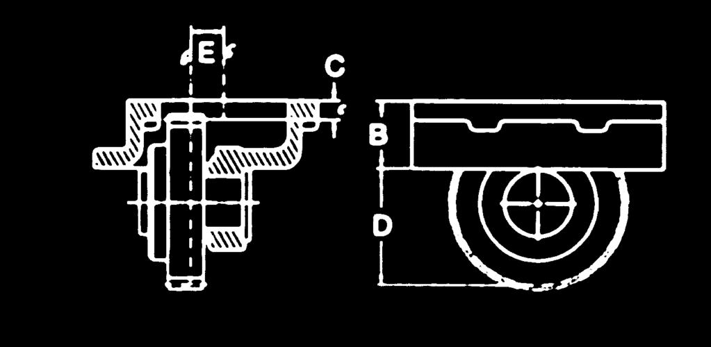
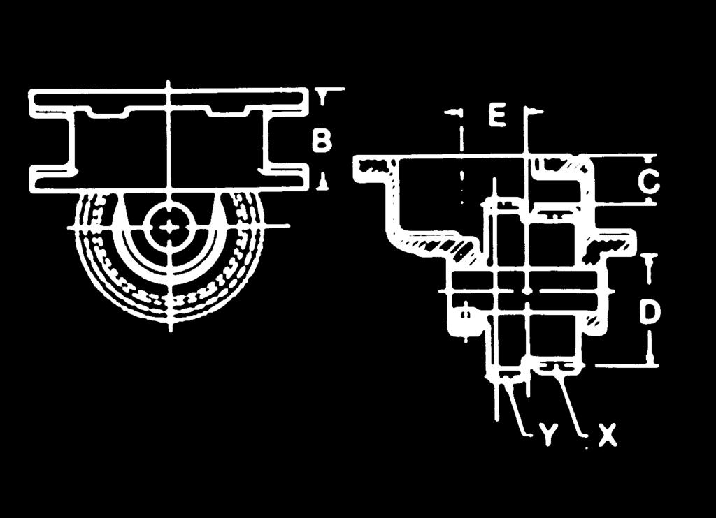
18 ADAPTER GEAR ASSEMBLIES Adapters: The application pages have a box for the inclusion of an adapter which can be used to change the rotation of the PTO output shaft as shown on this particular application. The adapter shown relates to all the PTOs shown above it on that page. Adapters are available for only 6-bolt type PTOs. Refer to the listed footnotes before specifying an adapter. These footnotes typically show changes that are required of the TG Series to make it mount properly to the adapter. Example: The Ford/ZF S5-42 Application page ZEDF-2 TWO FORWARD ONE REVERSE ADAPTER RECOMMENDED TO CHANGE ROTATION 6, 7 40TZ Change PTO as described in footnote, add 23M MK0115. Refer to Adapter Gear Assemblies in index for additional space requirements The adapter to change rotation is 40TZ Because the adapter has a cluster gear it changes the requirement of the PTO input gear from the Z99 input to the U68 input. This requirement covers the use of an SG Series as well as the TG or RG Series. The assembly of the PTO changes because of the cluster gear, and this is noted in the footnote. FOOTNOTES: 6 When using adapter to change rotation, multiply speed shown by.76. Change SG or RG Series to U68 input gear and 2 assembly. The RG Series will require 23M60200S + 20MK6603. Change the TG Series to S68 (#03T94243) and 2 assembly and add 23M60200S + 20MK6602. TG Series 18 ratio interferes with adapter and can not be used. The footnote indicates that all PTOs used will have a change in the output shaft speed by a factor of 76%. The footnote also informs you that the TG Series PTO input should be sold as an S68 input gear instead of the U68. (This is because the TG ratio gears will interfere with the adapter cluster gear.) The 15 and 18 ratio gears are too large to fit this adapter and can t be used. Finally, if you are going to use the RG Series PTO, then a spacer and stud kit need to be added to order. FIGURE 1 SOLID BODY-SINGLE GEAR FIGURE 2 ANGULAR OFFSET 18 (Rev )
19 ADAPTER GEAR ASSEMBLIES DIMENSIONAL DATA MODEL NO. FIG. FOOTNOTE GEAR DATA DIMENSIONS APPL. TEETH A B C D 40TU U (74.1) (41.9) (27.5) (78.7) 40TM M (74.1) (41.9) (27.1) (79.2) 40TF F (85.9) (15.7) (28.0) (128.2) MODEL NO. FIG. FOOTNOTE LOCA. APPL. TEETH B C D E 40TG , 4, 5, 8 40TG , 4, 5, 8 X G73 22 Y U68 20 X U68 20 Y G (58.6).682 (17.3) (28.5) (58.6).682 (17.3) (28.5) 10 40TI , 4, 6 Y I (58.6).653 (16.6) (28.9) 10 40TM , 3, 4, 5, 9 40TM , 3, 4, 5, 9 X M65 22 Y U68 20 X U68 20 Y M (58.6).682 (17.3) (30.0) (58.6).682 (17.3) (30.0) 10 40TN7910-1/-2 2 3, 4, 6 X or Y N (58.6).634 (16.1) (29.3) 10 40TU6810-1/-2 2 2, 3, 4, 5, 6 X or Y U (58.6).682 (17.3) (29.1) 10 40TZ9210-1/-2 2 3, 4, 5, 6 X or Y Z (58.6).835 (21.2).954 (24.2) 10 40TZ , 4, 5, 7 40TZ , 4, 5, 7 40TZ , 4, 5, 9 40TZ , 4, 5, 9 X Z99 31 Y U68 20 X U68 20 Y Z99 31 X Z10 31 Y U68 20 X U68 20 Y Z (58.6).682 (17.3) (31.8) (58.6).682 (17.3) (31.8) (58.6).682 (17.3) (29.8) (58.6).682 (17.3) (29.8) 10 1 Shipped with 23M60062S to be used on PTO side of adapter. 2 Requires 23M60032S sold separately. 3 Includes stud kit to mount adapter. 4 The C dimension does not reflect the idler shaft offset. This adapter is designed for a standard mount PTO. 5 Derate PTO application by 30% when using this adapter. Do not use this adapter for continuous duty applications. 6 Adapter is single gear design. 7 TG-S68 PTO input gear required. Add 23M60200S+20MK6603 to PTO requirement. 8 TG-S68 PTO input gear required. 18 ratio cannot be used. Add 23M60200S+20MK6603 to PTO requirement. 9 TG-S68 PTO input gear required. 15 & 18 ratio cannot be used. Add 23M60200S+20MK6603 to PTO requirement. (Rev ) 19


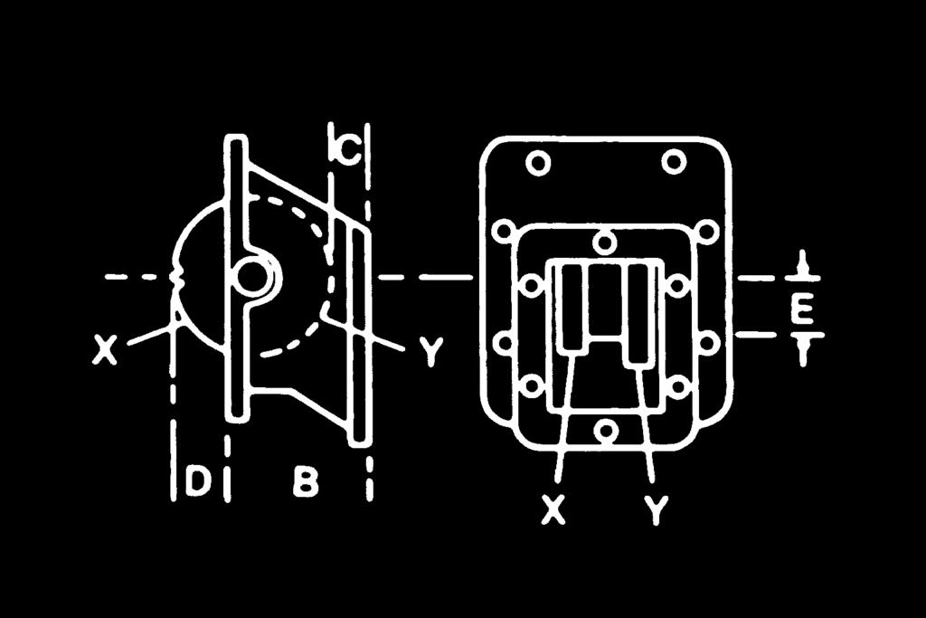
20 ADAPTER GEAR ASSEMBLIES FIGURE 5 ANGULAR FIGURE 6 8-BOLT TO 6-BOLT 55º 45º 30º F OFFSET FIGURE 7 ISUZU ADAPTERS FIGURE 8 NISSAN ADAPTER FIGURE 9 HORIZONTAL OFFSET FIGURE 10 NISSAN ADAPTER FIGURE 11 SINGLE GEAR OFFSET FIGURE 12 6-BOLT MACK ADAPTER FIGURE 13 8-BOLT MACK ADAPTER Footnotes for page 21 1 Shipped with 23M60062S to be used on PTO side of adapter. 2 Requires 23M60032S sold separately. 3 Includes stud kit to mount adapter. 4 The C dimension does not reflect the idler shaft offset. This adapter is designed for a standard mount PTO. 5 Derate PTO application by 30% when using this adapter. Do not use this adapter for continuous duty applications. 6 Adapter is not designed for PTO use. Use to re-position Eaton Inertia Brake only. 20
21 MODEL NO. FIG. FOOT- NOTE ADAPTER GEAR ASSEMBLIES DIMENSIONAL DATA GEAR DATA DIMENSIONS LOCA. APPL. TEETH B C D E 40TU , 4 X U (71.9) (23.2) (27.6) 30º 40TA , 4 Y A (72.2) (22.2) 1.12 (28.4) 30º 40TF8430-1/2 5 3, 4 X F (74.4) (25.6) (27.5) 30º 40TU , 4 X U (78.3) (27.6) (28.1) 45º 40TA6855-1/2 5 3, 4 X A (77.1) (25.3) (29.1) 55º X U (35.4) 40TF , 4, (78.0) (27.2) 55º Y F (20.6) 40TU , 4 X U (78.0) (27.2) (28.1) 55 40TU , 4 Y U (78.0) (27.2) (28.1) 55 40TW , 4 X W (78.0) (26.8) (28.5) 55 40TU , 4 40TU , 4 40TN , 5 40TC TF TF TF TF TS TS X U68 25 Y U68 18 X U68 18 Y U68 25 X N63 14 Y U80 24 X C94 29 Y U68 24 X F61 19 Y U68 24 X F63 22 Y U68 24 X F66 23 Y U68 24 X F83 26 Y U68 24 X S71 25 Y U68 24 X S73 24 Y U (95.5) (26.1) 3.76 (95.5) (26.1) (35.4).812 (20.6).812 (20.6) (35.4).71 (18.0).71 (18.0) (108.0).715 (18.2) (-23.7) (56.8) (27.6) (64.8) (36.4) (56.8) (27.6) (66.8) (36.4) (56.8) (27.6) (69.0) (36.4) (56.8) (27.6) 2.76 (70.1) (36.4) (56.8) (27.6) (65.3) (36.4) (56.8) (27.6) (70.2) (36.4) (56.8) (27.6) (69.0) (36.4) 29TK (36.3) (27.6) (38.1) 29TK (50.4) (27.6) (10.6) 40TI X I (44.4).698 (17.7) (70.3).843 (21.4) 40TN X N (44.4).499 (12.7) (75.7).843 (21.4) 40TM TM X M66 25 Y S68 23 X M66 33 Y U (81.3) (32.6) (59.0) (86.8) (21.1) (49.1) 25 (Rev ) 21
22 PTO TORQUE AND HORSEPOWER RATINGS Intermittent service refers to an On-Off operation under load. If maximum HP and/or torque is used for extended periods of time, (5 min. or more every 15 min.) this is considered Continuous Service and HP rating of PTO should be reduced by multiplying intermittent value below by.70. Applications with PTO output shaft speeds above 2,000 RPM, regardless of duration, are to be considered Continuous duty. MAX rated output shaft speed for all Muncie Power PTOs is 2,500 RPM. Fire Pump applications are calculated within a different category listed on page 3 and are derated by multiplying intermittent value below by.80. Below is a chart showing the Intermittent and calculated continuous Torque rating of the PTOs included in this catalog. The Application pages may have lower ratings for these PTOs listed. The Application page rating may be adjusted to limit the PTO output to a rating which will not exceed the transmission manufacturers rating. The transmission manufacturer does not differentiate between Intermittent and Continuous; therefore, the Application page rating is never to be exceeded. Refer to this page when there is a question of the rating (Intermittent or Continuous) for the PTO as it is manufactured. PTO SERIES SPEED RATIO INTERMITTENT HP@1000 RPM INTERMITTENT TORQUE LBS.FT. CONTINUOUS TORQUE LBS.FT. INTERMITTENT [KW]@1000 RPM INTERMITTENT TORQUE [NM] ONTINUOUS TORQUE [NM] PTO SERIES SPEED RATIO INTERMITTENT HP@1000 RPM INTERMITTENT TORQUE LBS.FT. CONTINUOUS TORQUE LBS.FT. INTERMITTENT [KW]@1000 RPM INTERMITTENT TORQUE [NM] ONTINUOUS TORQUE [NM] SG [19] [176] [123] TG CS6/8 SH6/ [40] [386] [270] [38] [366] [256] [35] [332] [232] [33] [312] [218] [33] [312] [218] [29] [278] [195] 12H [30] [284] [199] 13H [30] [284] [199] 15H [28] [264] [185] 18H [25] [237] [166] [43] [407] [285] [43] [407] [285] [43] [407] [285] [43] [407] [285] [43] [407] [285] [39] [373] [261] [39] [373] [261] [39] [373] [261] [57] [542] [379] [57] [542] [379] [53] [508] [356] [46] [441] [309] [46] [441] [309] RG N/A [19] [190] N/A RL N/A [28] [271] N/A N/A [28] [271] N/A [71] [678] [475] [63] [610] [427] [63] [610] [427] [58] [556] [389] [58] [556] [389] [53] [508] [356] [53] [508] [356] [50] [475] [332] [43] [407] [285] FR [22] [203] [142] FR [27] [258] [181] **FR66 limit in mobile applications continuous intermittent FR64/ [27] [258] [181] The HC, PZ, and RS Series PTOs vary in their torque and horsepower ratings and are based on the transmission on which they are mounted. The torque rating of these PTOs are shown on their respective application pages or you may contact Muncie Power Products, Inc. Product Engineering Dept. for this information. FR66/ FR6Q CD [29] [271] [190] 22 ** [16] [162] [162] [57] [542] [379] [54] [522] [365] [51] [488] [342] [48] [456] [319] [44] [420] [294] [37] [352] [246] [32] [305] [214] CD [85] [813] [569] CS10 /11 CS24 /25 HS [71] [678] [475] [68] [651] [456] [64] [610] [427] [60] [569] [398] [54] [522] [365] [46] [440] [308] [46] [440] [308] [43] [414] [290] [42] [400] [280] [41] [393] [275] [36] [338] [237] [36] [338] [237] [28] [271] [190] [46] [440] [308] [43] [414] [290] [41] [393] [275] [36] [338] [237] CS [85] [813] [569] MC [76] [739] [517] [70] [664] [465] [57] [542] [542] [57] [542] [542] [59] [563] [563] [51] [488] [488] [48] [461] [461] [44] [420] [420] [39] [373] [373] [37] [359] [359] [29] [278] [278] 22 (Rev )
23 DIRECT MOUNTED HYDRAULIC PUMP Hydraulic pumps connected to PTOs by means of a spline hydraulic pump mounting are rated the same as the hydraulic pump shaft by the pump manufacturer. Muncie Powwer PTO output shafts are made to ANSI or SAE standards. Pump manufacturers may rate their input shafts based on displacement. Be sure to select a shaft size which is adequate to handle your needs. It is recommended that you use the largest shaft available for the PTO which would be compatible to your hydraulic pump. PTO OUTPUT SHAFT RATINGS SHAFT LIMITS: SHAFT STL ⅝" - 9T 5,490 ¾" - 11T 10,114 ⅞" - 13T 16,500 1" - 15T 25,650 1¼" - 14T 33,300 The pump input shaft can withstand torque up to the designed shaft torque limitation (STL). This figure is based on multiplying the pump cu.in. displacement x the pump pressure. Tandem pumps are two pumps with individually calculated STLs added together not to exceed the limitation figure. Use this chart as a guide. Check with your pump manufacturer. They will have their own ratings and the lower rating is to be used. REMOTE DRIVE SHAFT Refer to the table for the proper driveline series. Torque and horsepower are based on typical PTO driven applications and are intermittent ratings. Driveshaft applications are dependent on many factors including (but not limited to) torque, shaft length, shaft series, and speed. Tubular drive shaft are recommended for all PTO driveshaft applications. High cyclic power operations require the use of the largest output shaft and Muncie recommends the splined output shafts with companion flanges for these applications. Series Cross & Bearing MAX 1,000 RPM 1000 MK-2X X X X 125* *Limited By PTO Max. Speed (RPM) Max. TJA A *3,500* 5 *3,000* 5 2, , , , DRIVELINE ANGLES For installations with angles in the top and side views use this formula to compute the true joint angle (TJA): TJA = A 2 + B 2 Round, keyed output shafts are susceptible to failure by high cyclic loading. Applications requiring round, keyed PTO output shafts should use the severe duty rating shown on this chart. A TOP VIEW TRANSMISSION * For speeds over 2,500 RPM contact Muncie for Approval. PTO B PUMP PUMP TORQUE RATINGS FOR REMOTE SHAFTS PTO SHAFT (Round, Keyed or External Spline) INTERMITTENT (lb.ft.) DUTY CYCLE CONTINUOUS (lb.ft.) SEVERE (lb.ft.) 7 8" w/¼" Key " w/¼" Key ¼" w/ ⁵ ₁₆" Key " 21T Spl w/comp Flg ½" 10T Spl w/comp Flg Detailed information is available for drivelines from Neapco and Spicer. Maximum Drive Shaft Lengths (Tubular Shafts): - Length = CL to CL of joints Series Tube Length Max RPM x.065w 52" 2,500 RPM x " 2,500 RPM 1280/ x.083w 55" 2,500 RPM x.083w 76" 2,500 RPM 23
24 PTO SHAFT ROTATION The PTO output shaft rotation as listed on the application page is shown as it relates to the vehicle crankshaft rotation. The rotation of the vehicle crankshaft is always clockwise when viewed from the front of the vehicle. The PTO output shaft designated as Crnk means that the shaft is turning the same rotation as the vehicle crankshaft. The PTO output shaft designated as Opp means that the shaft is turning the opposite rotation as the vehicle crankshaft. These two terms are shown in the figures below. The rotation of the output shaft may be changed by the use of the appropriate gear adapter as shown on the previous pages. The rotation of the output shaft is important in specifying the proper driven component of the PTO. When using a gear type hydraulic pump the rotation is often designated as right hand or left hand. The chart below shows which rotation hydraulic pump to use when the PTO application page designates a Crnk or Opp rotation PTO shaft. The chart also shows the proper side of the hydraulic pump for the inlet and the outlet hose connections. This is viewing the hydraulic pump with the pump s body offset down (belly down). 24
25 NOMOGRAPH INSTRUCTIONS FOR PUMP SELECTION The nomographs on the following pages are designed to help in the selection of a hydraulic pump. Follow the instructions below, then refer to the pump specifications before the final pump selection is made. 1. Ask customer what the desired engine speed is and mark it on the left bar of (Engine Speed) Nomograph #1 (For Our Example: 2,000 RPM). 2. Customer will need to supply the required flow rate for the accessory. Plot this value on the right bar (Pump Flow) of Nomograph #2 (Our Example: 15 GPM). 3. Customer will need to supply the transmission model number and the desired location for the PTO. By using this QR Catalog, select a PTO and plot its percent to engine speed on the center bar (PTO%) of Nomograph #1 (Our Example: 60%). 4. Draw a straight line through the engine speed and PTO% and extend it through the right bar (PTO Shaft Speed), record the result and mark it on the left bar of Nomograph #2 (Our Example: 1,200 RPM). 5. Draw a straight line on Nomograph #2 connecting the PTO/Pump Shaft Speed (1,200 RPM) with the desired output flow rate (15 GPM). The line crosses the center bar at the pump that will provide that flow at the input RPM calculated (Our Example: PL14). 6. The pump information on page 28 is provided to assist in pump selection based on rated pressure and RPM. If the pump selected in step 5 does not perform in the range desired then selection of another pump might be necessary. This can be done by changing the PTO% and or engine speed. Also, if the line does not cross at a pump listed, then the PTO% or engine speed will have to be changed. This can be done by using the Nomograph in reverse order. 25
26 NOMOGRAPH #1 PTO OUTPUT SPEED ENGINE SPEED NOMOGRAPH #2 PUMP SELECTION OUTPUT FLOW * Be sure that the pump series you have selected is compatible with the flow and pressure requirements of your system and that it is not operated above or below its rated speed. Refer to page 28 for pump performance ratings. 26
27 NOMOGRAPH #3 HP SPEED TORQUE NOMOGRAPH #4 GPM PSI HP 27
28 PUMP SPECIFICATIONS BY SERIES PUMP SERIES FLOW DISPLACEMENT MAX. PRESSURE GPM LPM CU.IN. CM 3 PSI (BAR) MAX. RPM MIN. RPM*** PF (4).24 (4) 3,625 (250) 3,500 1,000 PF (6).37 (6) 3,625 (250) 3, PF (8).49 (8) 3,625 (250) 3, PF (10).61 (10) 3,625 (250) 3, PF (11).67 (11) 3,625 (250) 3, PF (14).85 (14) 3,625 (250) 3, PF (16).98 (16) 3,625 (250) 3, PF (19) 1.16 (19) 3,625 (250) 2, PF (23) 1.40 (23) 3,400 (235) 2, PF (27) 1.65 (27) 2,750 (190) 2, PF (31) 1.89 (31) 2,400 (165) 2, PF (33) 2.01 (33) 2,250 (155) 2, Refer to Brochure MP08-06 for Dimensions and Specifications PH (10).62 (10) 3,500 (241) 3,500 1,000 PH (20) 1.24 (20) 3,500 (241) 3, PH (25) 1.55 (25) 3,500 (241) 3, PH (30) 1.86 (30) 3,250 (224) 3, PH (36) 2.17 (36) 2,900 (200) 3, PH (41) 2.48 (41) 2,500 (172) 3, Refer to Brochure MP15-17 for Dimensions and Specifications PK (16).24 (16) 3,000 (207) 3, PK (24) 1.47 (24) 3,000 (207) 3, PK (32) 1.97 (32) 3,000 (207) 3, PK (40) 2.46 (40) 3,000 (207) 3, PK (48) 2.96 (48) 3,000 (207) 2, PK (57) 3.45 (57) 2,500 (172) 2, PK (65) 3.94 (65) 2,500 (172) 2, Refer to Brochure MP15-12 for Dimensions and Specifications PL (52) 3.18 (52) 3,000 (207) 3, PL (63) 3.82 (63) 3,000 (207) 3, PL (73) 4.46 (73) 3,000 (207) 3, PL (85) 5.20 (85) 2,500 (172) 3, PL (93) 5.73 (93) 2,500 (172) 2, PL (104) 6.37 (104) 2,500 (172) 2, PL (115) 7.01 (115) 2,000 (138) 2, Refer to Brochure MP15-11 for Dimensions and Specifications W06 6 (23) 1.45 (23.9) 4,350 (300) 3, W08 8 (30) 1.96 (32.2) 4,350 (300) 3, W11 11 (42) 2.42 (39.7) 4,350 (300) 3, W13 13 (49) 2.92 (47.9) 4,000 (275) 3, W15 15 (57) 3.46 (56.8) 3,750 (260) 2, W17 17 (64) 3.96 (65.0) 3,500 (240) 2, W19 19 (72) 4.37 (71.6) 3,250 (225) 2, Refer to Brochure MP15-13 for Dimensions and Specifications 28 (Rev )
29 PUMP SERIES FLOW DISPLACEMENT MAX. PRESSURE GPM LPM CU.IN. CM 3 PSI (BAR) MAX. RPM MIN. RPM*** X14 14 (53) 3.18 (52.1) 4,350 (300) 3, X16 16 (60) 3.83 (62.9) 4,350 (300) 3, X19 19 (72) 4.44 (72.8) 3,750 (260) 3, X23 23 (87) 5.20 (85.3) 3,500 (240) 2, X25 25 (95) 5.69 (93.4) 3,250 (225) 2, X27 27 (102) 6.35 (104) 3,000 (210) 2, X30 30 (114) 7.01 (115) 2,500 (190) 2, X33 33 (125) 7.78 (128) 2,500 (190) 2, X36 36 (136) 8.43 (138) 2,250 (155) 2, Refer to Brochure MP15-14 for Dimensions and Specifications Y26 26 (98) 6.19 (101) 4,000 (275) 3, Y31 31 (117) 7.16 (117) 4,000 (275) 2, Y35 35 (132) 8.04 (132) 3,750 (260) 2, Y40 40 (151) 9.25 (151) 3,500 (240) 2, Y44 44 (167) (166) 3,250 (225) 2, Y49 49 (185) (184) 3,000 (210) 2, Y53 53 (200) (204) 2,750 (190) 2, Y62 62 (235) (236) 2,500 (172) 2, Refer to Brochure MP15-15 for Dimensions and Specifications MLSM (102) 6.10 (102) 3,000 (207) 2, MLSM (117) 7.11 (117) 3,000 (207) 2, MLSM (132) 8.20 (132) 2,750 (190) 2, MLSM (151) 9.27 (151) 2,750 (190) 2, MLSM (166) (166) 2,500 (170) 2, Refer to Brochure MP15-37 for Dimensions and Specifications DumpPumps ** S3LD (24) 1.47 (24) 2,500 (172) 2, S3LD (40) 2.46 (40) 2,500 (172) 2, S3LD (57) 3.45 (57) 2,500 (172) 2, E(H)3XL (87) 5.20 (85) 2,500 (172) 2, E(H)3XL (102) 6.37 (104) 2,500 (172) 2, Refer to Brochures MP15-10 and MP15-09 for Dimensions and Specifications Pumps are cast iron, three piece construction, with heavy duty roller or sleeve bearings, and pressure balanced wear plates. Call Muncie Power Products for detailed specifications or application assistance. (Rev ) * Theoretical 1,000 RPM. ** Intermittent Cycles Only. *** Higher RPMs are generally recommended for continuous operation. To calculate torque requirement, use formula: T = CID x PSI

 Activation connections: These")


 Z 12V")
30 SPECIAL PTOS There are application pages which include special PTOs for modern, foreign transmissions. Please note that mounting kits and required spacers are not included with the PTO model unless specified. The options for these special PTOs vary for each model as described below. PTO MODELS WITH HC6/HC8 SERIES Shift Options: A Manual air shift E 12V Electric/Air shift C Cable shift (Certain Models Only) Activation connections: These shift options are similar installations to the TG series. Output Option: B 1000 Series companion flange. Requires a flange yoke to attach to a 1000 Series drive shaft. K SAE-B 2 & 4 bolt hydraulic pump mount. Kit adapts to ISO type output with a coupler. Kit number: 606X HC6S-Nissan PTO SAE-B Kit PTO MODELS RS4S This model is designed for rear mounting to the countershaft of a manual or automated manual transmissions. Please note if a special transmission shaft adaptation is listed on the application page as these may be required for installation, but not included in the PTO model number. RS4S-P86 Volvo Adaptation RS4S-P86 Eaton Adaptation RS4S-P82 SERIES OR RS4S-P86 SERIES Shift Options: A Manual air shift E 12V Electric/Air shift (The exception is the Freedomline RS4S-P82Z1-E1CX, this PTO is provided with a special wiring harness required by ZF/Meritor for proper PTO operation) Z 12V Electric/Air shift with special wiring harness for ZF/Meritor Freedomline and RS4S-P86Z series PTO) Output Options: C 1310 series companion Flange K SAE-B 2- or 4-bolt hydraulic pump mount. Due to overhung load issues, this option limits the pump to 25 lbs. maximum system weight. Kit to convert to K : 606X80A0000 (P82 also requires P00 adapter for hydraulic mount) I DIN 5462 hydraulic mount, limited to pump system weight of 30 lbs. (P82 requires P00 adapter) RS4S-P82Z Freedomline RS4S-P86 Mercedes Adaptation (Rev )
ADAPTER GEAR ASSEMBLIES
 ADAPTER GEAR ASSEMBLIES PARTS LIST AND SERVICE MANUAL Adapter Gear Assemblies are normally used to reverse rotation of the PTO output shaft and to clear mounting obstructions. Standard adapters will move
ADAPTER GEAR ASSEMBLIES PARTS LIST AND SERVICE MANUAL
 ADAPTER GEAR ASSEMBLIES PARTS LIST AND SERVICE MANUAL Adapter Gear Assemblies are normally used to reverse rotation of the PTO output shaft and to clear mounting obstructions. Standard adapters will move
CS6 & CS8 CLUTCH SHIFT PTO
 CS6 & CS8 CLUTCH SHIFT PTO CLUTCH SHIFT PTO YOU CAN PROVIDE POWERSHIFTED PTO POWER FOR AU- TOMATIC AND STANDARD TRANSMISSIONS WITH MUN- CIE S CS6 & CS8 PTO. The internal wet clutch permits easy engagement
TG SERIES PTO PARTS LIST AND SERVICE MANUAL. Muncie Power Products, Inc.
 TG SERIES PTO PARTS LIST AND SERVICE MANUAL Muncie Power Products, Inc. TG SERIES PTO EXPLODED VIEW Torque to 18 ft.lbs. Torque to 18 ft.lbs. Torque to 18 ft.lbs. Torque to 9 ft.lbs. # # # L, K, P & V
TG SERIES PTO PARTS LIST AND SERVICE MANUAL
 TG SERIES PTO PARTS LIST AND SERVICE MANUAL Muncie Power Products, Inc. TG SERIES PTO EXPLODED VIEW Torque to 18 ft.lbs. Torque to 18 ft.lbs. Torque to 9 ft.lbs. # # # L, K, P & V HYD. FLANGE M & N HYD.
Muncie Power Products, Inc.
 SH6 & SH8 SERIES POWER TAKE-OFF PARTS LIST AND SERVICE MANUAL Muncie Power Products, Inc. SH6 & SH8 SERIES PTO EXPLODED VIEW PTO ASSEMBLY ARRANGEMENTS NO. 1 ASSEMBLY NO..3 ASSEMBLY 25 ft.lbs. 35 ft.lbs.
82 SERIES PTO PARTS LIST AND SERVICE MANUAL
 82 SERIES PTO PARTS LIST AND SERVICE MANUAL Muncie Power Products, Inc. 18 ft.lbs. (use 242 Loctite) 82 SERIES PTO EXPLODED VIEW 16 ft.lbs. 10 ft.lbs. (use 242 Loctite) 18 ft.lbs. 45 ft.lbs. (use 242 Loctite)
RG SERIES PTO PARTS LIST AND SERVICE MANUAL
 RG SERIES PTO PARTS LIST AND SERVICE MANUAL Muncie Power Products, Inc. Member of the Interpump Hydraulics Group General Offices and Distribution Center P.O. Box 548 Muncie, IN 47308-0548 (765) 284-7721
parts list and service manual
 CS0 & CS Series clutch shift pto parts list and service manual U.S. Pat.,2,0 for the allison world transmission CS0 & CS Series Clutch shift PTO Exploded View parts list and description item qty part number
Muncie Power Products, Inc.
 RG SERIES POWER TAKE-OFF PARTS LIST AND SERVICE MANUAL RG SERIES PTO 18 ft.lb. 10 ft.lb. HELICAL GEAR CAN BE EITHER RIGHT HAND, OR LEFT HAND (SHOWN). MODEL NUMBER CONSTRUCTION RG 6D U68 13 L 3 B X PTO
CS24/25 SERIES CLUTCH SHIFT PTO
 CS/ SERIES CLUTCH SHIFT PTO PARTS LIST AND SERVICE MANUAL Muncie Power Products, Inc. CS/ PTO EXPLODED VIEWS Detail B Detail A Detail E Detail C Detail D DETAIL A OUTPUT SHAFT ASSEMBLY 7 CS/ STANDARD OUTPUT
PARTS LIST AND SERVICE MANUAL
 CD40 SERIES PTO PARTS LIST AND SERVICE MANUAL HEAVY DUTY, CONSTANT DRIVE PTO FOR THE ALLISON WORLD TRANSMISSION CD40 SERIES CONSTANT DRIVE PTO EXPLODED VIEW CD40 COVER DETAIL (Backside) PTO ASSEMBLY ARRANGEMENTS
CS41 SERIES CLUTCH SHIFT PTO
 CS41 SERIES CLUTCH SHIFT PTO PARTS LIST AND SERVICE MANUAL Patent #2004200334 Muncie Power Products, Inc. CS41 SERIES CLUTCH SHIFT PTO EXPLODED VIEW 46 2 MUNCIE POWER PRODUCTS, INC. PARTS LIST AND DESCRIPTION
Parts list and service manual
 FR Series pto Parts list and service manual fr63/fr64 series pto exploded view Gasket Ford Supplied Reuse Gasket Found on Opening or Order 13T39089 Separately FR63 Bearing Removal Location Exhaust Port
CS24/25 SERIES CLUTCH SHIFT PTO
 CS/ SERIES CLUTCH SHIFT PTO PARTS LIST AND SERVICE MANUAL Muncie Power Products, Inc. CS/ PTO EXPLODED VIEWS Detail B Detail A Detail E Detail C Detail D DETAIL A OUTPUT SHAFT ASSEMBLY 7 CS/ STANDARD OUTPUT
FA6B Series PTO PARTS LIST AND SERVICE MANUAL. Muncie Power Products, Inc.
 FAB Series PTO PARTS LIST AND SERVICE MANUAL Muncie Power Products, Inc. FAB PTO EXPLODED VIEWS Detail A Detail B Detail F Detail C Detail E Detail D Detail A Output Shaft Assembly 5 9 5 8 0 Detail AA
CD05/10 SERIES PTO PARTS LIST AND SERVICE MANUAL
 CD05/0 SERIES PARTS LIST AND SERVICE MANUAL Heavy Duty, Constant Drive MUNCIE POWER PRODUCTS, INC. MUNCIE POWER PRODUCTS, INC. CD05/0 EXPLODED VIEWS Detail A Detail B Detail E Detail C Detail D 3 3 CD05/0
HINO PTO INTERFACE PTO INSTALLATION AND OPERATOR S MANUAL KEEP IN VEHICLE. FOR Allison 2500 With CS6B-A67**-S3*H PTO
 KEEP IN VEHICLE READ OPERATING INSTRUCTIONS INSIDE BEFORE OPERATING PTO HINO PTO INTERFACE PTO INSTALLATION AND OPERATOR S MANUAL FOR Allison 2500 With CS6B-A67**-S3*H PTO Muncie Power Products, Inc. Important
PARTS LIST AND SERVICE MANUAL
 CS0 & CS SERIES CLUTCH SHIFT PTO PARTS LIST AND SERVICE MANUAL Muncie Power Products, Inc. ft.lb. See Cover Detail To Trans. Port 3 33 CS0 SERIES PTO EXPLODED VIEW 3 0 9 3 9 3 3 ft.lb. 3 3b 9 3 ft.lb.
WARNING THIS SYMBOL WARNS OF PERSONAL INJURY OR DEATH. Page 2
 WARNING ALWAYS READ AND UNDERSTAND THE ENTIRE MANUAL COMPLETELY BEFORE INSTALLATION OR OPERATION OF PTO AND DRIVEN EQUIPMENT INCLUDING THESE WARNINGS AND OPERATOR S INSTRUCTIONS IN SECTION 3! ALWAYS DISENGAGE
F SERIES GEAR PUMP. 2 Muncie Power Products, Inc Muncie Power Products, Inc.
 ALL NEW DESIGN F SERIES GEAR PUMP ALL NEW DESIGN Ultimate power and performance in a small package best describes the all new F Series gear pumps. Designed exclusively for those low flow applications.
MINING FORESTRY MOBILE TRUCK AGRICULTURE MATERIAL HANDLING OPTIMUM
 MINING FORESTRY MOBILE TRUCK AGRICULTURE MATERIAL HANDLING OPTIMUM Muncie Power Products OPTIMUM Series gear pumps/motors offer premier performance for a wide variety of applications across several industries.
PART LIST P T O P T O S E R I E S S E R I E S
 PART LIST P T O 1 0 0 0 S E R I E S P T O 2 0 0 0 S E R I E S Bezares U.S.A. PART LIST & TABLE 1 Nov. 2017 Bezares U.S.A. PART LIST & TABLE 2 Nov. 2017 PTO 1000 & 1010 Series SAE B 2/4 Bolt PART 1 4 Screw
FA SERIES FORD AUTOMATIC PTO
 FA SERIES FORD AUTOMATIC PTO PARTS LIST AND SERVICE MANUAL Muncie Power Products, Inc. FA SERIES PTO EXPLODED 18 Ft.Lb. 5 Ft.Lb. 18-25 Ft.Lb. Gasket Ford Supplied 44 Reuse Gasket Found on Opening or Order
17 SERIES DIRECTIONAL CONTROL VALVE
 17 SERIES DIRECTIONAL CONTROL VALVE 17 GPM (65 LPM) 3,500 PSI (242 Bar) Sectional Type Solenoid Operated Muncie s 17 Series solenoid operated control valves provide flexibility you have never had before.
Muncie Power Products, Inc.
 A SERIES POWER TAKE-OFF PARTS LIST AND SERVICE MANUAL Muncie Power Products, Inc. EXPLODED VIEWS Detail C A SERIES PTO EXPLODED VIEWS Detail D Detail A Detail B DETAIL A IDLER SHAFT ASSEMBLY 4 5 DETAIL
RM SERIES PTO INSTALLATION AND OPERATOR S MANUAL KEEP IN VEHICLE FOR ALLISON TC10 READ OPERATING INSTRUCTIONS INSIDE BEFORE OPERATING PTO
 KEEP IN VEHICLE READ OPERATING INSTRUCTIONS INSIDE BEFORE OPERATING PTO RM SERIES PTO INSTALLATION AND OPERATOR S MANUAL FOR ALLISON TC10 Muncie Power Products, Inc. WARNING! ALWAYS READ AND UNDERSTAND
Chelsea Power Take-Offs. P.T.O. General Information
 Chelsea Power Take-Offs P.T.O. General Information WARNING FAILURE OR IMPROPER SELECTION OR IMPROPER USE OF THE PRODUCTS AND/OR SYSTEMS DESCRIBED HEREIN OR RELATED ITEMS CAN CAUSE DEATH, PERSONAL INJURY
Muncie Power Products, Inc.
 FR66 SERIES POWER TAKE-OFF PARTS LIST AND SERVICE MANUAL NOTE: FOR UNITS BUILT AFTER JUNE 2013 Muncie Power Products, Inc. Other FR66 Literature IN10-01 Installation and Operator's Manual MP15-08 Specifications
Illustrated Parts Breakdown Manual EZ LOADER. Model EZ12 (Pre-01/08)
") Illustrated Parts Breakdown Manual EZ LOADER Model EZ12 (Pre-01/08) Xtreme Manufacturing 1415 West Bonanza Road Las Vegas, NV 89106 (702) 858-2404 www.xtrememanufacturing.com Copyright 2008 By Xtreme Manufacturing
Illustrated Parts Breakdown Manual EZ LOADER Model EZ12 (Pre-01/08) Xtreme Manufacturing 1415 West Bonanza Road Las Vegas, NV 89106 (702) 858-2404 www.xtrememanufacturing.com Copyright 2008 By Xtreme Manufacturing
FEATURES: APPLICATIONS:
 Ultimate power and performance in a small package best describes the all new F4 Series gear pumps. The pressure balanced bushing blocks and sleeve bearings provide both extra long life and high performance.
Features: Applications: 12 standard sizes Pressures to 3625 PSI (250 Bar)
") Ultimate power and performance in a small package best describes the all new F4 Series gear pumps. The pressure balanced bushing blocks and sleeve bearings provide both extra long life and high performance.
Ultimate power and performance in a small package best describes the all new F4 Series gear pumps. The pressure balanced bushing blocks and sleeve bearings provide both extra long life and high performance.
210, 220, 230 and 240 Series 2 Speed Single Axles Catalog PB-92126
 Revised 11/02 210, 220, 230 and 240 Series 2 Speed Single Axles Catalog PB-92126 Strength Power Speed Agility MERITOR PARTS. RIGHT FROM THE START. HOW TO USE THIS CATALOG There are four basic carriers
Muncie Power Products, Inc.
 FR6/6/67 SERIES POWER TAKE OFF PARTS LIST AND SERVICE MANUAL Muncie Power Products, Inc. MUNCIE POWER PRODUCTS, INC. FR6/6/67 PTO EXPLODED VIEWS Detail A Detail B Detail E Detail D Detail C DETAIL A OUTPUT
Muncie Power Products, Inc.
 EXTENDED SHAFT SERIES PARTS LIST AND SERVICE MANUAL CD10 SERIES EXTENDED SHAFT SERVICE PARTS LIST 1 1 11 1 6 8 9 10 CD10 LEFT SIDE ALLISON 000 ITEM QTY DESCRIPTION 9TA96A SAE-B 9TA97A DIN 6 9TA98A SAE-BB
Vickers 45. VMQ Series 30 Vane Pumps. Fixed Displacement, For Industrial and Mobile Applications (4.188)
") [ (4.188) 49,4 (1.94) /21,8 /.86) 174,7/172,3 (6.88/6.78) 332,9/33,5 (13.11/13.1) "M" is marked if metric port threads No marking if inch port threads AS-568-152 O-ring Vickers 45 65,3 (2.57) 13 (5.1 VMQ
[ (4.188) 49,4 (1.94) /21,8 /.86) 174,7/172,3 (6.88/6.78) 332,9/33,5 (13.11/13.1) "M" is marked if metric port threads No marking if inch port threads AS-568-152 O-ring Vickers 45 65,3 (2.57) 13 (5.1 VMQ
Muncie Power Products, Inc.
 SSH & SSV SPLIT SHAFT SERIES PTO PARTS LIST AND SERVICE MANUAL Muncie Power Products, Inc. TABLE OF CONTENTS Section 1 SSH2 & SSV* PTO Specifications... Page SSH2 Specifications...3 SSV* Specifications...4
PTO INSTALLATION & OPERATOR S MANUAL
 PTO INSTALLATION & OPERATOR S MANUAL EX-DRIVE Shaft Extension KEEP IN VEHICLE READ OPERATING INSTRUCTIONS INSIDE BEFORE OPERATING PTO Muncie Power Products, Inc., Member of Interpump Group TABLE OF CONTENTS
FR6Q PTO PARTS LIST AND SERVICE MANUAL. Muncie Power Products, Inc.
 FR6Q PTO PARTS LIST AND SERVICE MANUAL Muncie Power Products, Inc. MODEL NUMBER CONSTRUCTION FR6Q - F1 09-6 N X Model: FR6Q Ford 6-Bolt Quiet Transmission Gear: F1 Ford 6R10 Internal Gear Ratio: 09 0.90:1
MT155 DRIVE AXLE PARTS CATALOGUE
 MT155 DRIVE AXLE PARTS CATALOGUE IMPORTANT INFORMATION AFTERMARKET PARTS WARRANTY We warrant all new parts for one year from date of shipment to the buyer against defective material or workmanship (but
H Series. HECO Interchange Series Power Wheel. Planetary Gear Drive
 H Series HECO Interchange Series Power Wheel Planetary Gear Drive CONTENTS Introduction 3 Auburn Gear, Inc. versus HECO - Gear and Bearing Ratings Comparison 4-5 Model 6 Center Flange Shaft Output Drives
Please visit for the latest version of these installation instructions.
 Please visit www.blueox.com for the latest version of these installation instructions. Attachment Tab Height: 16 Serial Number Attachment Tab Width: 35 Please read BOTH these and the General Information
Power Wheel Model 8 Planetary Gear Drives AuburnGear.com
 Power Wheel Model 8 Planetary Gear Drives 260.92.30 AuburnGear.com MODEL 8 Features & A2 Integral Brake Information...3 MODEL 8 WHEEL DRIVES Double Reduction...4 with A2 Series Integral Parking Brake...6
RTH2610B/RT3210HV DRIVE AXLE PARTS CATALOGUE
 RTH2610B/RT3210HV DRIVE AXLE PARTS CATALOGUE IMPORTANT INFORMATION AFTERMARKET PARTS WARRANTY We warrant all new parts for one year from date of shipment to the buyer against defective material or workmanship
DRIVELINE COMPONENTS CATALOG CENTER YOKES, TUBE YOKES AND BALL STUD TUBE YOKES
 DRIVELINE COMPONENTS CATALOG CENTER YOKES, TUBE YOKES AND BALL STUD TUBE YOKES JUNE 2008 Supersedes Section 5, Dated November 2005 Change Log: 10/2/08 pg 5 140-28-17 centerline to point of weld dimension
4SPEED AUXILIARY TRANSMISSIONS
 WEATHERLY INDEX 08 Transmission Parts List............... - 0 6 January, 978 70 AUXILIARY TRANSMISSION Supersedes Parts Lists T0-6 Dated September, 973 and T-0-6 Dated February, 975 SPEED AUXILIARY TRANSMISSIONS
Muncie Power Products, Inc.
 EX DRIVE SHAFT EXTENSION PARTS LIST AND SERVICE MANUAL Muncie Power Products, Inc. XD10 A0XX X C C R X XD10 - For CD10 XS10 - For CS10 XS2 - For CS2 XS1 - For CS1 A0XX - Allison 000 Series A0XX - Allison
INSTALLATION AND MAINTENANCE MANUAL
 TYPE 2 PTO INSTALLATION AND MAINTENANCE MANUAL P.O. Box 8148 Wichita Falls, Texas 76307 1600 Fisher Rd. Wichita Falls, Texas 76305 Phone: (940) 7611971 Fax: (940) 7611989 www.wptpower.com email: info@wptpower.com
Power Wheel Model 8 Series B Planetary Gear Drives AuburnGear.com
 Power Wheel Model 8 Series B Planetary Gear Drives 260.92.30 AuburnGear.com SERIES B WHEEL DRIVES Model 8 Series B Features & A2 Integral Brake Information...3 Double Reduction...4 with A2 Series Integral
RTH2610B/RT3210HV DRIVE AXLE PARTS CATALOGUE
 RTH2610B/RT3210HV DRIVE AXLE PARTS CATALOGUE IMPORTANT INFORMATION AFTERMARKET PARTS WARRANTY We warrant all new parts for one year from date of shipment to the buyer against defective material or workmanship
Hi-Tech & Pro Magnum Roller Rocker Arms
 Hi-Tech & Pro Magnum Roller Rocker Arms Thank you for choosing COMP Cams products; we are proud to be your manufacturer of choice. Please read this complete instruction sheet carefully (including the application
Please visit for the latest version of these installation instructions.
 Please visit www.blueox.com for the latest version of these installation instructions. BX1139 2018 Jeep Wrangler / Wrangler Unlimited (JL) (All Models w/standard Bumper) Attachment Tab Height: 18 Serial
BX1681. Please read BOTH these Installation Instructions and the General Towing Instructions before attempting to install or operate this equipment.
 Serial Number BX1681 2007-13 Chevy Pickup 1500, 2500 & 3500 New Style Heavy Duty (2WD/4WD), 2007-11 GMC Pickup 2500 & 3500 New Style, 2008-10 GMC Yukon 2500 Please read BOTH these and the General Towing
User Manual SH Slag Removal Tool for use on laser cutting machines with minimum 1.25 between slats
 User Manual SH2 67087 Slag Removal Tool for use on laser cutting machines with minimum 1.25 between slats 1. Description The tool is moved along the slats on the bed of a laser machine to remove slag that
Please visit for the latest version of these installation instructions.
 Please visit www.blueox.com for the latest version of these installation instructions. BX2409 2009-18 Dodge Ram 1500 Sport/ST/Laramie Limited Please read BOTH these and the General Information sheet prior
Please visit for the latest version of these installation instructions.
 Please visit www.blueox.com for the latest version of these installation instructions. BX2412 2016-18 Ram 1500 Rebel 2016-18 Ram 1500 Bighorn/Laramie/Laramie Longhorn (Chrome Bumpers) 2018 Ram 1500 (Metal
Please visit for the latest version of these installation instructions.
 Please visit www.blueox.com for the latest version of these installation instructions. BX3796 Attachment Tab Height: 13-1/2 Serial Number Attachment Tab Width: 24 Please read BOTH these and the General
Transmission Connector Kit (Includes throttle stud, two 3/8" nuts, a 3/8" bolt and corrector plate)
") INSTRUCTIONS 304147 EZ-EFI Cable Bracket Kit Thank you for choosing products; we are proud to be your manufacturer of choice. Please read this instruction sheet carefully before beginning installation,
INSTRUCTIONS 304147 EZ-EFI Cable Bracket Kit Thank you for choosing products; we are proud to be your manufacturer of choice. Please read this instruction sheet carefully before beginning installation,
Model 340 Tune-Up Kit Instructions
 Model 340 Tune-Up Kit Instructions Jacobs P/N 019654 tune-up kit instructions Tune-up Kit Contents Illus. No. Jacobs P/N Part Name Quantity Per Kit 4 020229 Upper Seal Ring 3 5 001082 Center Seal Ring
Please visit for the latest version of these installation instructions.
 Please visit www.blueox.com for the latest version of these installation instructions. BX2668 2016-19 Ford Explorer (Includes ACC, EcoBoost & Shutters) Attachment Tab Height: 16-1/2 Serial Number Attachment
203 TRANSFER CASE CONVERSION
 203 TRANSFER CASE CONVERSION PN:501 OUR FOUR TRANSFER CASE WEDGES REPLACE THE SPIDER GEARS AND CONNECT THE PLANETARY GEAR AND REAR OUTPUT SHAFT MAKING ONE UNIT. SIMILAR IN DESIGN & FUNCTION TO THE BEST
Muncie Power Products, Inc.
 MC SEIES POWE TAKE-OFF PATS LIST AND SEVICE MANUAL Muncie Power Products, Inc. MODEL NUMBE CONSTUCTION MC - A0 07 - HX BB PX Model: MC Medium Duty Clutch Shift 0-Bolt Transmission ear: A0 Allison 000/4000
SHAW-BOX INSTRUCTIONS AND PARTS LIST SHAW-BOX RIGID MOUNT I-BEAM AND PATENTED TRACK TROLLEYS (PUSH & HAND GEARED - 1/2 THRU 15 TON RATED LOADS)
") SHAW-BOX INSTRUCTIONS AND PARTS LIST SHAW-BOX RIGID MOUNT I-BEAM AND PATENTED TRACK TROLLEYS (PUSH & HAND GEARED - 1/2 THRU 15 TON RATED LOADS) GENERAL SHAW-BOX Rigid Mount I-Beam Trolleys are designed
SHAW-BOX INSTRUCTIONS AND PARTS LIST SHAW-BOX RIGID MOUNT I-BEAM AND PATENTED TRACK TROLLEYS (PUSH & HAND GEARED - 1/2 THRU 15 TON RATED LOADS) GENERAL SHAW-BOX Rigid Mount I-Beam Trolleys are designed
Advanced Technology Tension Clutches
 P-220 819-0339 Advanced Technology Tension Clutches Installation Instructions Contents Installation................................. 2 Clutch Repair On the Shaft.................. 4 Clutch Service Major.......................
HI/LO CYLINDER (Y SERIES) INSTALLATION, OPERATING & MAINTENANCE MANUAL
 INSTALLATION, OPERATING & MAINTENANCE MANUAL") HI/LO CYLINDER (Y SERIES) INSTALLATION, OPERATING & MAINTENANCE MANUAL 545 Hupp Avenue Jackson, Michigan 49204 Ph: 517-787-9444 Fx: 517-787-7585 www.airhydraulics.com info@airhydraulics.com Serial No.
HI/LO CYLINDER (Y SERIES) INSTALLATION, OPERATING & MAINTENANCE MANUAL 545 Hupp Avenue Jackson, Michigan 49204 Ph: 517-787-9444 Fx: 517-787-7585 www.airhydraulics.com info@airhydraulics.com Serial No.
TCI Ford C-6 TransBrake Valve Body Shift Pattern: Park, Reverse, Neutral, First, Second, Third
 1 INSTRUCTIONS TCI 421500 Ford C-6 TransBrake Valve Body Shift Pattern: Park, Reverse, Neutral, First, Second, Third Thank you for choosing TCI products; we are proud to be your manufacturer of choice.
Please visit for the latest version of these installation instructions.
 Please visit www.blueox.com for the latest version of these installation instructions. Attachment Tab Height: 21 Serial Number Attachment Tab Width: 31.25 Please read BOTH these and the General Information
Please visit for the latest version of these installation instructions.
 Please visit www.blueox.com for the latest version of these installation instructions. Attachment Tab Height: 25 Serial Number Attachment Tab Width: 22-1/2 Please read BOTH these and the General Information
1 CMP throttle stud, two 3/8" nuts, a 3/8" bolt and corrector plate) CMP R4 Universal Cable 1
 CMP R4 Universal Cable 1") INSTRUCTIONS 370816 TCI TV Cable Bracket For Holley Carburetors Thank you for choosing TCI products; we are proud to be your manufacturer of choice. Please read this instruction sheet carefully before
INSTRUCTIONS 370816 TCI TV Cable Bracket For Holley Carburetors Thank you for choosing TCI products; we are proud to be your manufacturer of choice. Please read this instruction sheet carefully before
ROUSH Short Throw Shifter Kit
 ROUSH Short Throw Shifter Kit Part Number 1310R7400 Application: 2010 Ford Mustang GT Installation Instructions Before installing your ROUSH Performance Product(s), read through the entire installation
TRU-TIME ADJUSTABLE CAM GEAR Part Number: BK & BK
 TRU-TIME ADJUSTABLE CAM GEAR Part Number: 23-801BK & 23-802BK! WARNING: This installation is not for the mechanically challenged! If you are not mechanically inclined or do not understand the procedure
ASSEMBLY OF TROLLEY TO HOIST
 INSTRUCTIONS AND PARTS LIST RIGID MOUNT I-BEAM AND PATENTED TRACK TROLLEYS (PUSH & HAND GEARED - 1/2 THRU 15 TON RATED LOADS) GENERAL Yale Rigid Mount I-Beam Trolleys are designed especially for use on
Installation Instructions
 P-214 819-0518 PCB-1225/1000, PCB-1525/1225 Clutch-Brake, Pin Drive, Spline Drive PCBC-1225/1000, PCBC-1525/1225 Clutch-Brake/Coupling Installation Instructions Contents Installation Instructions PCB-1225/1000
Please visit for the latest version of these installation instructions.
 Please visit www.blueox.com for the latest version of these installation instructions. BX2414 2019 Ram 1500 (Includes Rebel) (No Classic) Attachment Tab Height: 17 Serial Number Attachment Tab Width: 38.5
Please visit for the latest version of these installation instructions.
 Please visit www.blueox.com for the latest version of these installation instructions. 2015-18 Ford Edge (Includes ACC) (No 2.0L EcoBoost or Sport) Attachment Tab Height: 15 Serial Number Attachment Tab
Please visit for the latest version of these installation instructions.
 Please visit www.blueox.com for the latest version of these installation instructions. Attachment Tab Height: 24-1/2 BX2675 (Incudes Super Duty & ACC) Serial Number Attachment Tab Width: 34-1/2 Please
Highly Styled, Low Cost Serpentine Drive
 Revised 2-27-08 Highly Styled, Low Cost Serpentine Drive Installation Instructions Ford 460 Big Block Kit #30275 (with Power Steering) and #30270 (without Power Steering) Included Parts List Main Front
Please visit for the latest version of these installation instructions.
 Please visit www.blueox.com for the latest version of these installation instructions. DH2400 (Long & Standard Box) Please read these in their entirety prior to installing or operating this equipment.
LOR Series Trig-O-Matic Lite Overload Release Clutch
 LOR Series Trig-O-Matic Lite Overload Release Clutch P-3029-BG LOR Series Installation and Operation An Altra Industrial Motion Company Contents I. Introduction A. Operating Principle... 3 B. Torque Adjustment...
POWER TAKE OFF S 1000/2000 SERIES 1200 SERIES 1000 SERIES 3100/3150/3250 SERIES 3250 SERIES 2000 SERIES 3000 SERIES 3100 SERIES
 talogo_usa_maquetación 1 31/01/2014 14:14 Página 1 atalogo_usa_maquetación 1 31/01/2014 14:14 Página 2 POWER TAKE OFF S 1000/2000 SERIES 1200 SERIES Our 1000 and 2000 series PTO s have been engineered
P-286 (WC-58/59) Wichita Clutch. Service & Installation Instructions
 Wichita Clutch. Service & Installation Instructions") P-286 (WC-58/59) Wichita Clutch Standard Ventilated Clutch Special Ventilated Clutch Service & Installation Instructions Contents Installation...2 W1 Shaft to Shaft Mounting...2 W2 Mid-Shaft Mounting...3
P-286 (WC-58/59) Wichita Clutch Standard Ventilated Clutch Special Ventilated Clutch Service & Installation Instructions Contents Installation...2 W1 Shaft to Shaft Mounting...2 W2 Mid-Shaft Mounting...3
Page D165DC MARKIV OPERATORS MANUAL
 1 D165DC MARKIV OPERATORS MANUAL 2 WARNING - SAFETY NOTE IMPORTANT - DO NOT OPERATE THIS EQUIPMENT UNTIL YOU READ AND FULLY UNDERSTAND THIS MANUAL AND ITS ASSEMBLY INSTRUCTIONS ALWAYS WEAR EYE PROTECTION
PREMIER, MARINE, & STANDARD
 INSTA LLATION INSTRUCTION AND SERVICE MANUAL I TITAN 12" x 2" BRAKES FREE BACKING. UNI-SERVO. DUO-SERVO PREMIER, MARINE, & STANDARD Limited Warranty TITAN Inc. ("TITAN') warrants its products to be free
Please visit for the latest version of these installation instructions.
 Please visit www.blueox.com for the latest version of these installation instructions. BX1726 (All Models) (No Active Shutters or E-Assist) Attachment Tab Height: 12 Serial Number Attachment Tab Width:
Please visit for the latest version of these installation instructions.
 Please visit www.blueox.com for the latest version of these installation instructions. Attachment Tab Height: 15-1/2 Serial Number Attachment Tab Width: 24 Please read BOTH these and the General Information
CS10 & CS11 SERIES CLUTCH SHIFT PTO
 CS0 & CS SERIES CLUTCH SHIFT PTO PRTS LIST ND SERVICE MNUL FOR THE LLISON WORLD TRNSMISSION U.S. Pat.,,06 Muncie Power Products, Inc. CS0 & CS SERIES CLUTCH SHIFT PTO EXPLODED VIEW a a MUNCIE POWER PRODUCTS,
AWE Touring Edition Track Edition Exhaust System W205 C43, C450 C400 Coupe Sedan. AWE website here
 Thank you for your purchase of the AWE Touring Edition or Track Edition Exhaust System for the 2015+ W205 C43, C450 or C400 Coupe or Sedan. For up to the minute fitment information, be sure to visit the
POWER END PARTS LIST
 GARDNER DENVER 302WPD997 Rev B April 2008 WELL SERVICING PUMP MODEL GD-600 POWER END PARTS LIST ECN 1040704 GD-600 WELL SERVICING PUMP MAINTAIN PUMP RELIABILITY AND PERFORMANCE WITH GENUINE GARDNER DENVER
Highly Styled, Low Cost Serpentine Drive
 Revised 10-13-08 Highly Styled, Low Cost Serpentine Drive Installation Instructions Chevy Big Block #21200 (without Power Steering) #21250 (with Remote Power Steering) #21255 (with Saginaw Power Steering)
Electrically Released Motor Brake Module for EM-MBFB and EUM-MBFB
 Electrically Released Motor Brake Module for EM-MBFB and EUM-MBFB P-1337-WE 819-0314 Installation Instructions An Altra Industrial Motion Company Warner Electric s MBFB series of Electrically Released
JOHN DEERE 9970 COTTON PICKERS
 PARTS CATALOG FOR Mud Hog System II Rear Wheel Drive FOR JOHN DEERE 9970 COTTON PICKERS Mud Hog Model Numbers Tread Center OEM Aftermarket JD40005 JD47655 82, 90, 94, 106 TUTHILL Drive Systems 9098 West
ENC 150 REFERENCE MANUAL ACU-RITE
 ENC 150 REFERENCE MANUAL ACU-RITE ENC150 Page Introduction... 2 Mounting Preparation... 3 Mounting Information... 4 Encoder Dimensions... 5 Backup Spar Dimensions... 6 Mounting Requirements... 7 Typical
Please visit for the latest version of these installation instructions.
 Please visit www.blueox.com for the latest version of these installation instructions. Attachment Tab Height: 16.5 Serial Number Attachment Tab Width: 30.5 Please read BOTH these and the General Information
Power Wheel. 1:1 Drives/Bearing Housings
 Power Wheel 1:1 Drives/Bearing Housings 260.925.3200 AuburnGear.com Table of Contents Power Wheel 1:1 Features...3 Model 6B 1:1 Direct Drives...4 Model 8B 1:1 8T2 Direct Drives...6 Model 8B 1:1 8S2 Direct
Please visit for the latest version of these installation instructions.
 Please visit www.blueox.com for the latest version of these installation instructions. BX1715 2014-15 Chevy Malibu (All Models) 2016 Chevy Malibu Limited (No Active Shutter or E-Assist) Attachment Tab
CDS-JOHN BLUE COMPANY
 VRH-1000 HYDRAULIC VARIABLE RATE DRIVE AND MOUNT KIT PARTS AND INSTRUCTION MANUAL CDS-JOHN BLUE COMPANY DIVISION OF ADVANCED SYSTEMS TECHNOLOGY, INC. 290 Pinehurst Drive - Huntsville, Alabama 35806 P.O.
Size 15 thru 29 Mesur-Fil Fluid Couplings P
 Size 15 thru 29 Mesur-Fil Fluid Couplings P-1033-2 Installation Instructions Installation Instructions Sizes 15-29 for HC, HCF, HCR and HSD Models These models are similar in their assembly procedures,
TECHNICAL SERVICE MANUAL
 Electronic copies of the most current TSM issue can be found on the Viking Pump website at www.vikingpump.com TECHNICAL SERVICE MANUAL VIKING HELICAL GEAR REDUCERS A, B, AND C SIZES SECTION PAGE ISSUE
Disc Valve Hydraulic Motors 4000 Compact Series
 Disc Valve Hydraulic Motors 10.2014 inspired hydraulics. Änderungen und Druckfehler vorbehalten 10.2014 EN EATON_Motoren english Port B Port A Features Shuttle Valve with Back- Pressure Relief Valve Highlights
Please visit for the latest version of these installation instructions.
 Please visit www.blueox.com for the latest version of these installation instructions. BX1126 Attachment Tab Height: 14-1/2 Serial Number Attachment Tab Width: 24 Please read BOTH these and the General