HI/LO CYLINDER (Y SERIES) INSTALLATION, OPERATING & MAINTENANCE MANUAL
|
|
|
- Roland Carpenter
- 6 years ago
- Views:
Transcription


1 HI/LO CYLINDER (Y SERIES) INSTALLATION, OPERATING & MAINTENANCE MANUAL 545 Hupp Avenue Jackson, Michigan Ph: Fx: Serial No.
2 TABLE OF CONTENTS General Safety..3 Warranty...3 Machine Guarding....3 Functional Description..4 Installation Guidelines..5 Cylinder Installation.6 Control Circuit Installation...7 Control Systems 7 Sequence of Approach Stroke to Power Stroke 8 Filling Procedure 9 Venting..9 Maintenance.10 Preventative Maintenance...11 Trouble Shooting...12 Parts Description/Location...13 Alignment Couplers
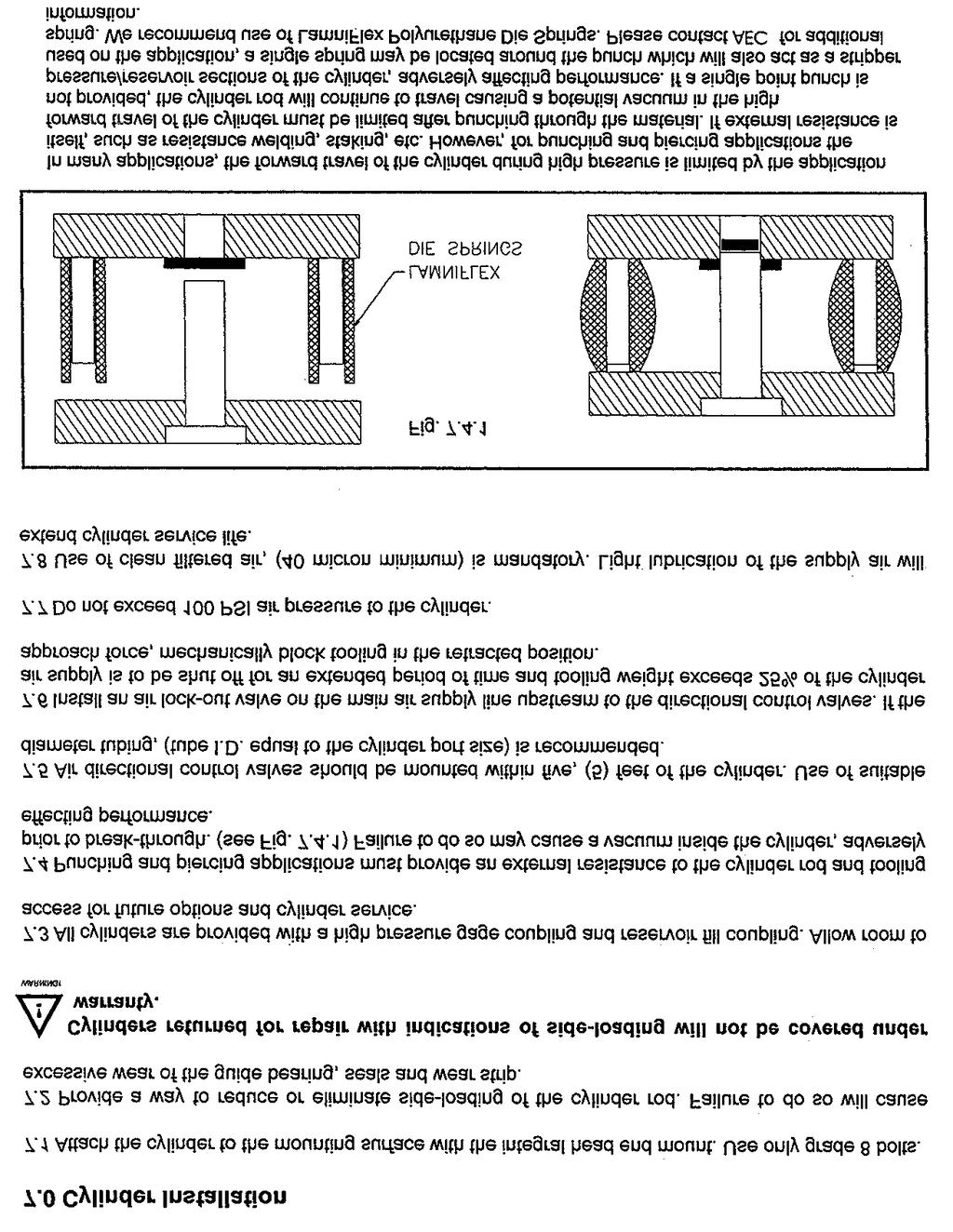
3 General Safety The cylinder are designed and built according to the state of the art utilizing CAD/CAM techniques, accepted industry standards, Quality Assurance systems and trained personnel. All cylinders are designed and manufactured to be operationally safe however; due to the nature of the product (i.e. pressing) there are areas of the product which cannot be protected at the factory. For this reason, good personal safety procedures and practices are required to protect the operator and maintenance personnel. Risks may arise if the cylinder is used or maintained by untrained personnel or in any way which is inconsistent with it s intended use and/or purpose. WARRANTY Air-Hydraulics, Inc. warrants to the original user that all products of our manufacture will be free from defects in material and workmanship and will possess the characteristics represented in writing by Air-Hydraulics, Inc. Claim for breach of the above warranty must be made within a period of (1) year from date of delivery to the user. Upon satisfactory proof of claim, Air-Hydraulics, Inc. will make any necessary repairs or corrections, or, at our option, replace defective parts at the factory, transportation charges prepaid. Charges for correcting defects will not be allowed, nor can Air-Hydraulics, Inc. accept goods returned for credit unless we are notified in writing and the return or correction is authorized by Air-Hydraulics, Inc. in writing. THE FOREGOING IIS IN LIEU OF ALL OTHER WARRANTIES, EXPRESSED OR IMPLIED, INCLUDING ANY WARRANTIES THAT EXTEND BEYOND THE DESCRIPTION OF THE PRODUCT. This paragraph sets forth the extent of the liability of Air-Hydraulics, Inc. for breach of any warranty in connection with the sale or use of our products. It is understood that Air-Hydraulics, Inc. will not be liable for consequential damages such as loss of profit, delays or expense, whether based on tort or contract. MACHINE GUARDING Machine guarding is the responsibility of the user. Provisions must be made to protect the operator and other employees from injury as a result of contact with the work in progress, moving parts, mechanical motions of the press, etc. Air-Hydraulics, Inc. cannot provide standard guarding for its presses due to the variety of tooling and applications used by press owners. However, Air-Hydraulics, Inc. will be happy to install guards and similar safety devices for operator protection. These safety devices must be produced at the request of and with design approval of the purchaser. 3
4 4
5 Installation Guidelines Attach the cylinder to the mounting surface using SAE grade 8 bolts of the largest diameter possible, with a locking washer or thread locking material (LocTite). Torque the bolt or SHCS the appropriate specifications Eliminate all possible side loading of the cylinder ram to tooling. Misalignment couplings or die-set couplings are highly recommended for all attachments (See page 14). Failure to do so could cause premature wear/failure of the cylinder wear-bands, seals and bearings and will void the manufacturer s warranty. All Hi/Lo cylinders are provided with a high pressure (hydraulic gauge port) coupling and fill port coupling as standard. The ports are labeled with yellow tags. Allow room to access for future servicing and control options. Hi/Lo cylinders can be installed in any position however, pleas be advised of the following. Horizontal mounting of the cylinder with a stroke length exceeding 4.00 must use the extended tie-rod option and make arrangements for a suitable attachment point at the cap end of the cylinder Rod lock or a pilot operated check valve is highly recommended for all vertical, rod down applications. Failure to install either safety device may cause cylinder drifting during shutdown periods and potentially create a vacuum inside the cylinder. 5
6 6
7 Control Circuit Installation 1. Use nylon tubing or rubber hose (Parker 801) is recommended for all pneumatic connections from the air directional control valves to the cylinder/reservoir/booster ports. Tubing I.D. should be at a minimum, equal to port size. 2. For best performance, all air directional control valves should be installed no further then 5 ft. from the cylinder 3. A 40 micron filtration system is mandatory. Air line lubrication is at the customer s option. 4. Install a lock-out/tag out safety valve up stream of the main air filter/regulator unit for shutdown and maintenance purposes. 5. Do not exceed 100 psi. air pressure to the cylinder 6. Please review the attached pneumatic control circuits. Mixing of 2-position, spring return and 3-position valve is not recommended. Important Note: The output (cylinder) rod must return to full retract position at all times. Do not limit the upstroke of this cylinder. NOTE The Air-Hydraulics press has been carefully and accurately built to give long, trouble free service if properly installed and maintained. Carefully follow the instructions given in this manual. During maintenance procedures to this press, make sure no dirt or foreign material enters the cylinders or other working parts. If you have unusual problems regarding controls or tooling, notify Air-Hydraulics, Inc., Jackson, Michigan and our Engineering Department will be glad to assist. Control Systems Hi/Lo Cylinder control circuits are similar to two typical air cylinders, with one cylinder extending before the other, and both retracting at the same time. Each cylinder requires (2) pneumatic directional control valves for operation. Pneumatic directional control valves can either be mechanical, solenoid, or remote air piloted. Valve size must be of suitable flow to permit proper cylinder function. Pneumatic flow control valves may be customer installed, (metered out) at cylinder ports B1 and B2 to control the speed of the cylinder and speed of the power stroke Ensure the main air supply is dry, clean (40 micron), and if possible lightly lubricated Unique to the Hi/Lo cylinder design is the ability to regulate the Approach Stroke force independently for the Power Stroke Force though the use of separate air regulators. 7
8 Stacking regulators installed on the valve manifold are recommended for best performance. All Air-Hydraulics Hi/Lo cylinders require a minimum of two (2) 4-way pneumatic directional control valves, a filter, regulator, lubricator unit, and a plant air supply for proper operation. Sequencing into high pressure can be accomplished using a time delay (electrical or pneumatic), a customer supplied proximity switch, or an end of stroke threshold sensor (PT or ELT series sensor). A unique feature of all Air-Hydraulics Hi/Lo cylinders is the ability to provide the power stroke anywhere within the total stroke of the cylinder. For this reason, we recommend the use of the PT or ELT series sensors to indicate when the work rod (and therefore tooling) has contacted the work surface. For best cylinder performance locate the directional control valves within five (5) feet the cylinder. Use nylon tubing equal to the respective port diameter for all air line connections from the directional control valves to the cylinder. A pneumatic flow control valve (meter out) may be installed at port B1 and/or port A1 to control cylinder approach and retract speed. Please refer to Installation Guidelines for additional information. Sequence of Approach Stroke to Power Stroke All Hi/Lo cylinders may be sequenced into the Power Stroke anywhere within the total stroke of the cylinder. Sequencing into the Power Stroke is customer defined. Recommended suggestions are: Time Delay, External Proximity Switch, or Threshold Sensor. ***Threshold sensors are installed directly into the cylinder B1 port which detects the exhausting air from the B1 port. Once the air has exhausted to 6 psi., indicating the cylinder rod and customer s tooling have made contact with the work surface. Refilling Cylinders All Hi/Lo cylinders are pre-filled and tested at the factory. The internal oil reservoir contains sufficient excess oil, (30%) that, with normal operation will operate millions of trouble free cycles. All cylinders are supplied with a reservoir fill coupling identified as F on the cylinder. The fill coupling is protected by a black rubber dust cap. Cylinders are also equipped with a low oil level indicator pin, which will extend outward approximately 3/16 when the cylinder requires refilling. To refill the cylinder, please use only the Hi/Lo fill unit with an ISO 32 hydraulic oil. 8
9 Filling Procedures 1. Fill the oil fill gun/unit with ISO 32 oil or equivalent 2. Retract the cylinder rod. 3. Depress the inner ring on the fill unit coupling (opening coupling), and depress the fill unit handle until all air has been vented from the fill unit tubing. Close the coupling 4. Remove the black rubber dust cover from the cylinder fill coupling. Connect fill unit to the cylinder 5. Repeatedly depress the fill unit handle until the unit handle becomes difficult to depress, cylinder is full. 6. Disconnect the fill unit from the cylinder. Replace the rubber dust cover. Push in the indicator pin. Procedure is complete Venting The Hi/Lo cylinders utilize a patented, total air/oil separation system which under normal operating conditions eliminates the possibility of air entering into the working and reservoir sections of the cylinder. Improper installation of oil pressure monitoring devices, and/or removal of either gauge or fill couplings will permit air to enter both oil sections of the cylinder. Air entrained in the oil will adversely affect cylinder performance. 1. Remove the fill line and coupling from the fill unit. Retract the cylinder rod and block up in the retract position 2. Remove the black rubber dust cover from the cylinder fill coupling. Connect the fill coupling to the cylinder. Place the opposite end of the fill line into a container of suitable size. 3. Depress and hold the manual override on the fast approach directional control valve until all the oil and air have been vented from the cylinder. Disconnect the fill coupling. Release the manual override. 4. Re-attach the fill unit coupling and line to the fill unit. Refill cylinder with oil (see fill procedure). 9
10 Maintenance Due to the simplicity of this Air-Hydraulics, Inc. hi-lo press the only maintenance requirements for the continued operation of this press are as listed below. Weekly checks: 1. Check oil level in air line lubricator. Check that the lubricator is working properly, i.e. dropping oil at the specified interval. This interval changes depending on the application, cleanliness of the air supply etc. a good starting point would be one drop per about every 12 press cycles. If however this causes oil to leak out of the mufflers, set for one drop every 18 to 20 cycles. 2. Check oil level in the main cylinder. This is done by looking at the oil level indicator at the back of the machine. If the plunger is pushed out this indicates a low oil level exists. Or look into the sight glass at the front of the machine, the piston should be visible in this window. If the piston is visible then the machine is o.k. to operate. 3. Check for air leaks in entire system. 4. Check for proper operation of the non-tie down system. Make sure that both palm buttons have to be actuated in order for the press to operate. Yearly checks or those to be done through a Preventative Maintenance schedule. 1. Check oil level in air line lubricator. Check that the lubricator is working properly, i.e. dropping oil at the specified interval. This interval changes depending on the application, cleanliness of the air supply etc. a good starting point would be one drop per about every 12 press cycles. If however this causes oil to leak out of the mufflers, set for one drop every 18 to 20 cycles. 2. Check oil level in the main cylinder. This is done by looking at the oil level indicator at the back of the machine. If the plunger is pushed out this indicates a low oil level exists. Or look into the sight glass at the front of the machine, the piston should be visible in this window. If the piston is visible then the machine is o.k. to operate. 3. Check for air leaks in entire system. 4. Check for proper operation of the non-tie down system. Make sure that both palm buttons have to be actuated in order for the press to operate. 5. Change the in line air filter cartridge. This will need to be done more often if it gets dirty. This will be indicated by a brownish color in the filter cartridge. 6. Check that all regulators are functioning properly and are able to change the pressure when they are adjusted. 7. Remove and clean the socket only of the threshold sensor. 8. Check that the flow control regulates the speed of the ram both in approach and retract. 9. Check for proper operation of the power valves. 10
11 Air-Hydraulics Hi/Lo Presses Model s AH5(x), AH10(x), AH15(x), AH20(x), AH30(x) and AH50(x) Preventative Maintenance 1. Before any preventative maintenance is performed, turn off air supply to press and block up ram, following OSHA and local Lock out/tag out procedures. 2. Keep the oiler/lubricator filled with Mobil DTE grade 24 or equivalent. Lubricator is adjusted at the factory, but it should be reviewed monthly. The larger the cylinder area, the more lubrication required. Use the following chart for a general rule of thumb. Model No. Cycles per drop AH4(x) 4 AH9(x) 4 AH14(x 4 AH20(x) 4 AH30(x) 5 AH50(x) 5 If the press ram is chattering, then increase the lubricator. If you are getting too much oil out of the exhaust air muffler, then decrease the lubricator. 3. Review and inspect air filter, it should be removed and replaced once filter element turns a tan or brownish color. 4. Check oil indicator, a round block located on the side of the cylinder. If brass pin pops out; cylinder is low on oil and needs to be refilled using an Air-Hydraulics, Inc. Oil fill Kit design specifically for this cylinder. 5. Check all safety devices DAILY for proper operation. If they are not functioning properly, DO NOT USE PRESS! 11
12 Trouble Shooting 12
13 Replacement Parts Description 13
14 14
ADJUSTABLE AIR PRESS
 ADJUSTABLE AIR PRESS MODELS 12-A, 28-A, 50-A INSTALLATION, OPERATING, and MAINTENANCE INSTRUCTIONS Black & Webster Assembly Equipment Division 545 Hupp Ave. P.O. Box 831 Jackson, Michigan 49204 Phone:
IMPACT HAMMER MODEL Z-2 & Z-6 PARTS AND OPERATING MANUAL
 IMPACT HAMMER MODEL Z-2 & Z-6 PARTS AND OPERATING MANUAL Black & Webster Products Division 545 Hupp Ave. P.O. Box 831, Jackson, Michigan 49204 Phone: (517-787-9444 Fax: (517) 787-7585 Email: info@airhydraulics.com
INSTRUCTIONS AND PARTS LIST FOR MODEL 25H HAND-OPERATED HYDRAULIC PRESS
 INSTRUCTIONS AND PARTS LIST FOR MODEL 25H HAND-OPERATED HYDRAULIC PRESS SETTING UP THE PRESS FOR OPERATION For shipping convenience, the gauge, pump handle, hoist crank, screw nose and base angles were
INSTRUCTIONS AND PARTS LIST FOR MODEL 25H HAND-OPERATED HYDRAULIC PRESS
 INSTRUCTIONS AND PARTS LIST FOR MODEL 25H HAND-OPERATED HYDRAULIC PRESS SETTING UP THE PRESS FOR OPERATION For shipping convenience, the gauge, pump handle, hoist crank, screw nose and base angles were
INSTRUCTIONS AND PARTS LIST FOR MODEL 125H & 150H HAND-OPERATED HYDRAULIC PRESS
 INSTRUCTIONS AND PARTS LIST FOR MODEL 125H & 150H HAND-OPERATED HYDRAULIC PRESS SETTING UP THE PRESS FOR OPERATION For shipping convenience, the gauge, pump handle, hoist crank, screw nose and base angles
Val-Matic Air / Oil Hydraulic Panel Pump Control System. Operation, Maintenance and Installation Manual
 Manual No. 5AOP-OM1-2 Val-Matic Air / Oil Hydraulic Panel Pump Control System Operation, Maintenance and Installation Manual INTRODUCTION... 1 RECEIVING AND STORAGE... 1 DESCRIPTION OF OPERATION... 1 INSTALLATION...
ACHL Series Pump. Operation and Maintenance Manual Air Driven, Hand Operated High Pressure Liquid Pump
 ACHL Series Pump Operation and Maintenance Manual Air Driven, Hand Operated High Pressure Liquid Pump Catalog: 02-9245ME February 2013 Model # Serial # Drawing # Order # Mfg. Date Table of Contents page
INSTRUCTIONS AND PARTS LIST FOR MODEL 70H & 75H HAND-OPERATED HYDRAULIC PRESS
 INSTRUCTIONS AND PARTS LIST FOR MODEL 70H & 75H HAND-OPERATED HYDRAULIC PRESS SETTING UP THE PRESS FOR OPERATION For shipping convenience, the gauge, pump handle, hoist crank, screw nose and base angles
ActuLink ABS Module - ABS-MOD-400
 Installation Instructions ActuLink ABS Module - ABS-MOD-400 For more information on the installation and operation of Tuson s towable ABS system, consult the installation and operations manuals for the
DAP-625S and DAP-875S
 AIR CHAMP PRODUCTS DAP-625S and DAP-875S (i) FORM NO. L-20078-B-0501 In accordance with Nexen s established policy of constant product improvement, the specifications contained in this manual are subject
INSTRUCTIONS AND PARTS LIST FOR MODEL 125H & 150H HAND-OPERATED HYDRAULIC PRESS
 INSTRUCTIONS AND PARTS LIST FOR MODEL 125H & 150H HAND-OPERATED HYDRAULIC PRESS SETTING UP THE PRESS FOR OPERATION For shipping convenience, the gauge, pump handle, hoist crank, screw nose and base angles
Loctite Spray Valve Controller Part Number EQUIPMENT Operation Manual
 Loctite Spray Valve Controller Part Number 1406023 EQUIPMENT Operation Manual Table of Contents 1 Please Observe The Following 3 1.1 Emphasized Sections 3 1.2 For your Safety 3 1.3 Unpacking and Inspection
CLEAN ROOM DEVICES, LLC "WHERE TUBING AND FITTINGS COME TOGETHER"
 CLEAN ROOM DEVICES, LLC "WHERE TUBING AND FITTINGS COME TOGETHER" CRD400 Fitting Inserter OPERATIONS MANUAL VERSION 3.1 LAST EDITED 03.08.11 DOCUMENT NUMBER 001 cleanroomdevices.com 1 Table of Contents
CLEAN ROOM DEVICES, LLC "WHERE TUBING AND FITTINGS COME TOGETHER"
 CLEAN ROOM DEVICES, LLC "WHERE TUBING AND FITTINGS COME TOGETHER" CRD600 Automatic Fitting Inserter OPERATIONS MANUAL VERSION 2.1 LAST EDITED 7.25.14 DOCUMENT NUMBER 001 cleanroomdevices.com 1 Table of
MODEL HX. Fail Safe Hydraulic Actuator FEATURES INTRO AVAILABLE SIZES. Hydraulic Actuation
 MODEL HX Fail Safe Hydraulic Actuator FEATURES Flexibility Model HX actuators can be adapted to operate valves from any manufacturer (interface information is required) and can be delivered with alternate
CRD600 Automatic Fitting Inserter
 CRD600 Automatic Fitting Inserter OPERATIONS MANUAL VERSION 2.3 LAST EDITED 12.07.2018 cleanroomdevices.com 1 Table of Contents Title Page.. 1 Table of Contents. 2 1.0 General Product & Safety Information...3
ORIGINAL INSTRUCTIONS G715A. Pneumatic-hydraulic Riveter E. Warner Ave Santa Ana, CA
 ORIGINAL INSTRUCTIONS G715A Pneumatic-hydraulic Riveter 1224 E. Warner Ave Santa Ana, CA 92705 www.cherryaerospace.com DESCRIPTION The Cherry G715A Pneumatic-Hydraulic Riveter is designed specifically
CRD610 Automatic Fitting Inserter
 CRD610 Automatic Fitting Inserter OPERATIONS MANUAL VERSION 1.2 LAST EDITED 12.12.2018 cleanroomdevices.com 1 Table of Contents Title Page. 1 Table of Contents...2 1.0 General Product & Safety Information....3
Rectangular Door L-VAT with pneumatic actuator double acting
 Rectangular Door L-VAT with pneumatic actuator double acting This manual is valid for the products: 0 7 5 1 0 U A 2 4 0 0 0 1 4 character option code Size 10... 46 x 236 12... 50 x 336 Actuator 24... without
Model P-40 & Model P-25 POWER PUSHER
 Power Pusher Description INSTRUCTION MANUAL The Power Pusher provides ram capability by using the spreading power of the POWER HAWK P-16 Rescue Tool. (The Power Pusher may also be used with other spreader
TBHD1 CRIMPING TOOL FOR THOMAS & BETTS TS DIES
 TBHD1 CRIMPING TOOL FOR THOMAS & BETTS TS DIES DATASHEET SEE PAGE 6 FOR IMPORTANT INFORMATION CONCERNING LIMITED WARRANTY, AND LIMITATION OF LIABILITY Operating instructions for the TBHD1 crimping tool
AIR CHAMP PRODUCTS. User Manual. Sheave & Pilot Mount Clutch-Brake Model BCB-275 FORM NO. L F-0414 FORM NO. L F-0414
 AIR CHAMP PRODUCTS User Manual Sheave & Pilot Mount Clutch-Brake Model BCB-275 i In accordance with Nexen s established policy of constant product improvement, the specifications contained in this manual
Guardian Steel Gear Shaft Coupling
 Guardian Steel Gear Shaft Coupling P-8609-GC GUA-MRK-DOC-026 Service & Installation Instructions TABLE OF CONTENTS NOTICES AND WARNINGS PAGE 2 SECTION 1 COUPLING OVERVIEW PAGE 3 SECTION 2 TOOLS/MATERIALS
OPERATIONS AND MAINTENANCE
 HELITILT OPERATIONS AND MAINTENANCE JB ATTACHMENTS - WHEN ONLY THE BEST WILL DO! INCREASE PRODUCTIVITY PROFITABILITY VERSATILITY CONTENTS 1.0 INTRODUCTION 1.0-1.4 2.0 SAFETY INSTRUCTIONS 2.0-2.5 3.0 STANDARDS
HV Gate Valve with pneumatic actuator
 HV Gate Valve with pneumatic actuator This manual is valid for the valve ordering number(s): 09134-_E14/24/34/44 09136-_E14/24/34/44 09138-_E14/24/34/44 09140-_E14/24/34/44 09144-_E14/24/34/44 The fabrication
Guardian FH Flywheel Coupling
 Guardian FH Flywheel Coupling P-8606-GC GUA-MRK-DOC-015 Service & Installation Instructions TABLE OF CONTENTS NOTICES AND WARNINGS PAGE 2 SECTION 1 COUPLING OVERVIEW PAGE 3 SECTION 2 TOOLS/MATERIALS REQUIRED
Firstmate Installation Manual and User's Guide May, 2003
 Firstmate Installation Manual and User's Guide May, 2003 Aqualogic Marine, Inc. 506-D Terry Lane - Washington - Missouri - 63090 Warning No user serviceable parts are located inside your Firstmate unit.
INSTALLATION AND OPERATING
 Publication T5-704, Rev. 4 Dated: November 1, 2006 INSTALLATION AND OPERATING MANUAL T50-P TURBOTWIN Engine Air Starter AN 99-448 TABLE OF CONTENTS Section Subject Page 1.0 General Information. 1 2.0 Orientation
TBM Series 3-Way Ball Valve
 www.simtechusa.com TBM Series 3-Way Ball Valve Operating, Installation, & Maintenance Manual Corrosion Resistant Fluid and Air Handling Systems. Dated 06-26-13 TBM Series Ball Valves SIMTECHRECOMMENDSREADINGTHEFOLLOWINGINFORMATIONPRIORTOINSTALLINGANDUSING
SERIES 740 VALVES PNEUMATIC DIRECTIONAL CONTROL
 SERIES 740 VALVES PNEUMATIC DIRECTIONAL CONTROL Specifications and features 4 Way / 2 & 3 Position Solenoid & Air Pilot Operated Diaphragm-Poppet Valve TECHNICAL DATA: Port Sizes: Integrated Fittings for
PCC O P E R A T I O N S. Pump Cycle Counter M A N U A L. Environmental Systems
 O P E R A T I O N S Environmental Systems PCC Pump Cycle Counter M A N U A L PO Box 3726 Ann Arbor, Michigan 48106-3726 (800) 624-2026 North America Only (734) 995-2547 Tele. (734) 995-1170 Fax info@qedenv.com
MODEL 5120 Tire Repair Station
 MODEL 5120 Tire Repair Station 00-0049 Installation, Operation & Repair Parts Information Branick Industries, Inc. 4245 Main Avenue P.O. Box 1937 Fargo, North Dakota 58103 REV01182017 P/N: 81-0058G CAUTION
Loctite 300ml Cartridge Pusher Part Number EQUIPMENT Operation Manual
 Loctite 300ml Cartridge Pusher Part Number 98022 EQUIPMENT Operation Manual Table Of Contents 1 PLEASE OBSERVE THE FOLLOWING... 3 1.1 EMPHASIZED SECTIONS...3 1.2 FOR YOUR SAFETY...3 1.3 ITEMS SUPPLIED...3
WATERBLAST HOSE REEL SYSTEM HWB HOSE REEL OPERATION AND MAINTENANCE MANUAL W A T E R J E T T O O L S
 WATERBLAST HOSE REEL SYSTEM HWB HOSE REEL OPERATION AND MAINTENANCE MANUAL W A T E R J E T T O O L S 466 S. SKYLANE DR. DURANGO, COLORADO 81303 970-259-2869 PHONE 970-259-2868 FAX www.stoneagetools.com
Product/ Title Guardian Super Flex Shaft Coupling Product/ Title
 Product/ Title Guardian Super Flex Shaft Coupling Product/ Title GUA-MRK-DOC-027 P-XXXX-GC Service&&Installation Installation Instructions Instructions Service An Altra Industrial Motion Company TABLE
FCB-450, LCB-600, MCB-800
 AIR CHAMP PRODUCTS User Manual FCB-450, LCB-600, MCB-800 Clutch-Brakes (i) In accordance with Nexen s established policy of constant product improvement, the specifications contained in this manual are
THUMB OPERATIONS AND MAINTENANCE MANUAL
 THUMB OPERATIONS AND MAINTENANCE MANUAL INTRODUCTION Thanks for choosing from JB Attachments range of earthmoving products. The contents of this manual should be thoroughly read and understood by the operators
2 Speed Hydraulic Hand Pump
 Porto-Power Blackhawk Automotive is a licensed trademark 2 Speed Hydraulic Hand Pump Operating Instructions & Parts Manual B65122 B65421 SFA Companies 10939 N. Pomona Ave. Kansas City, MO 64153 816-891-6390
Dual Phase Extraction Inlet. Patent No Installation Manual. P/N Rev
 Patent No. 6520259 Installation Manual P/N 95232 Rev 6-16-11 Table of Contents ing Extraction Inlets track changing water levels to maintain optimum performance 1.Component Identification Page 1 2. How
Guardian FBA Flywheel Coupling
 Guardian FBA Flywheel Coupling P-8602-GC GUA-MRK-DOC-010 Service & Installation Instructions TABLE OF CONTENTS NOTICES AND WARNINGS PAGE 2 SECTION 1 COUPLING OVERVIEW PAGE 3 SECTION 2 TOOLS/MATERIALS REQUIRED
Guardian NV Flywheel Coupling
 Guardian NV Flywheel Coupling P-8605-GC GUA-MRK-DOC-014 Service & Installation Instructions TABLE OF CONTENTS NOTICES AND WARNINGS PAGE 2 SECTION 1 COUPLING OVERVIEW PAGE 3 SECTION 2 TOOLS/MATERIALS REQUIRED
22/35 Two Stage Truck Jack
 Model 1003 CAPACITY RATCHETING JACK STAND DO NOT OVERLOAD AND. ST OVERLOADING CAN CAUSE DAMAGE AILURE TO,, OF OR ENSURE F BOTH ANDS ST ARE SET T SAME HEIGHT & HOLDING DOGS Y ENGAGED. ARE FULL THE ST AND.
CLEAN ROOM DEVICES, LLC "WHERE TUBING AND FITTINGS COME TOGETHER"
 CLEAN ROOM DEVICES, LLC "WHERE TUBING AND FITTINGS COME TOGETHER" CRD600AF Automatic Fitting Inserter With Auto Feed OPERATIONS MANUAL (Shown with optional alcohol dispenser) 1 VERSION 1.1 LAST EDITED
MEX (55) QRO (442) Web Controls
 QRO (442) Web Controls") Web Controls SINGLE AND DUAL ROTOR TENSION CONTROL BRAKES MODELS:,,,, AND INSTALLATION, OPERATION, AND MAINTENANCE INSTRUCTIONS Read this manual carefully, making full use of its explanations and instructions.
Web Controls SINGLE AND DUAL ROTOR TENSION CONTROL BRAKES MODELS:,,,, AND INSTALLATION, OPERATION, AND MAINTENANCE INSTRUCTIONS Read this manual carefully, making full use of its explanations and instructions.
Manifold w/ Needle Valve Instruction Manual
 MODELS: MFC2 & MFC4 Manifold w/ Needle Valve Instruction Manual SFA Companies 10939 N. Pomona Ave. Kansas City, MO 64153 Tel: 888-332-6419 - Fax: 816-448-2142 E-mail: sales@bvahydraulics.com Website: www.bvahydraulics.com
HSIV PLOW OPERATOR S MANUAL
 PLOW RWF INDUSTRIES 873 Devonshire Ave., Woodstock, Ontario N4S 8Z4 Tel: (519) 421-0036 Toll Free: 1-800-263-1060 Fax: (519) 421-0028 Email: parts@rwfbron.com JANUARY 2015 THE INFORMATION CONTAINED IN
Hydraulic Multi-Disc Brake H420 P-2067-WE SM320gb - rev 02/09
 Hydraulic Multi-Disc Brake H420 P-2067-WE SMgb - rev 02/09 Service Manual We, WARNER ELECTRIC EUROPE, 7, rue Champfleur, B.P. 20095, F-49182 St Barthélemy d Anjou Cedex declare that the brakes made in
SC HYDRAULIC ENGINEERING CORPORATION
 Designers and Manufacturers of Hydraulic and Pneumatic Equipment SC HYDRAULIC ENGINEERING CORPORATION 1130 Columbia Street - Brea, California 92821 - USA Phone (714) 257-4800 - Fax (714) 257-4810 10 SERIES
12 Volt Utility Controller for 4, 6, or 8 Brakes No
 12 Volt Utility Controller for 4, 6, or 8 Brakes No. 1300-76 P-1396-WE 819-0301 Installation Instructions An Altra Industrial Motion Company Contents Introduction... 2 Installation... 3 Mounting Under
II DISTRIBUTION & SUBSTATION TYPE C
 CapCheckIII DISTRIBUTION & SUBSTATION TYPE Ca p a c i t o r C h e c ke r Operating & Instruction Manual 1475 Lakeside Drive Waukegan, Illinois 60085 U.S.A. 847.473.4980 f a x 8 4 7. 4 7 3. 4 9 8 1 w e
Service Guide JATCO Environmental Protection Tank Model J-7000
 Service Guide JATCO Environmental Protection Tank Model J-7000 Listed below are a series of steps to follow if the JATCO tank fails to dump properly. #1. Be sure there is an adequate supply of gas pressure
8" - 12" Hydraulic Steel Squeeze Off Tool
 8" - 12" Hydraulic Steel Squeeze Off Tool ECN 19130 C812S Hydraulic Steel Squeeze Off Tool for Steel Pipe Page 1 of 8 This Footage Tools C812S Steel Squeeze Off Tool is sold with one pump configuration
Guardian HH Shaft Coupling
 Guardian HH Shaft Coupling P-8611-GC GUA-MRK-DOC-028 Service & Installation Instructions TABLE OF CONTENTS NOTICES AND WARNINGS PAGE 2 SECTION 1 COUPLING OVERVIEW PAGE 3 SECTION 2 TOOLS/MATERIALS REQUIRED
MODEL EF Full Circle Tire Spreader
 MODEL EF Full Circle Tire Spreader Installation, Operation & Repair Parts Information Branick Industries, Inc. 4245 Main Avenue P.O. Box 1937 Fargo, North Dakota 58103 REV. 062917 P/N: 81-0050C CAUTION
Raydot LLC 24 Actuator (115 VOLT)
") Installation, Operation & Parts Manual Read carefully the information provided. Retain manual for future reference. Raydot LLC 24 Actuator (115 VOLT) 145 Jackson Ave. S. Cokato, MN 55321-USA (320) 286-2103
Installation, Operation & Parts Manual Read carefully the information provided. Retain manual for future reference. Raydot LLC 24 Actuator (115 VOLT) 145 Jackson Ave. S. Cokato, MN 55321-USA (320) 286-2103
LUBRICATOR GUN INSTRUCTIONS-PARTS LIST. 10,000 psi (700 bar) Maximum Delivery Pressure. Detachable-type
 Maximum Delivery Pressure. Detachable-type") INSTRUCTIONS-PARTS LIST 306 460 INSTRUCTIONS This manual contains important warnings and information. READ AND KEEP FOR REFERENCE. Rev. E Supercedes D Detachable-type LUBRICATOR GUN 10,000 psi (700 bar)
INSTRUCTIONS-PARTS LIST 306 460 INSTRUCTIONS This manual contains important warnings and information. READ AND KEEP FOR REFERENCE. Rev. E Supercedes D Detachable-type LUBRICATOR GUN 10,000 psi (700 bar)
Read this entire manual before operation begins.
 Read this entire manual before operation begins. Record below the following information which is located on the serial number data plate. Serial No. Model No. Date of Installation Contents Specifications.............
Read this entire manual before operation begins.
 Read this entire manual before operation begins. Record below the following information which is located on the serial number data plate. Serial No. Model No. Date of Installation Contents Specifications.............
Heliporter. Owner s Manual. 150 Series. by Paravion Technology, Inc.
 Heliporter by Paravion Technology, Inc. Owner s Manual 150 Series Introduction Congratulations, you have purchased one of the finest helicopter ground handling vehicles on the market today. We at Paravion
Heliporter. Owner s Manual. H250 Series. By Paravion Technology, Inc. Copyright 2017 Paravion Technology, Inc.
 By, Owner s Manual H250 Series Copyright 2017, Introduction Congratulations, you have purchased one of the finest helicopter ground handling vehicles on the market today. We at, have strived to engineer
PARTS LIST. Guardian VR-Series. Material Pumps
 PARTS LIST Guardian VR-Series Material Pumps Table Of Contents Section 1 General Information 1:0 Technical Information... 1 1:1 Assembly Drawings... 5 1:2 Sub Assembly Drawings... 16 1:3 Maintenance...
Easy-On Wireless Tail Lights User s Guide
 Easy-On Wireless Tail Lights User s Guide TAKE NOTICE: BY INSTALLING OR OTHERWISE USING THE EASY-ON WIRELESS TAIL LIGHTS YOU AGREE TO FOLLOW THE BELOW DIRECTIONS CAREFULLY AND BE BOUND BY THE LIMITATION
AIR CHAMP PRODUCTS. User Manual. DAP-625S and DAP-875S FORM NO. L D-0914
 AIR CHAMP PRODUCTS User Manual DAP-65S and DAP-875S FORM NO. L-0078-D-09 In accordance with Nexen s established policy of constant product improvement, the specifications contained in this manual are subject
MANUAL SERVICE MANUAL FOR HYDRASTAR HYDRAULIC TRAILER BRAKE ACTUATORS
 MANUAL 440-1008 SERVICE MANUAL FOR HYDRASTAR HYDRAULIC TRAILER BRAKE ACTUATORS THIS DOCUMENT TO BE USED FOR HBA-10, HBA-12, HBA-16, MHBA-10, MHBA-12, MHBA-16 ACTUATORS ECN 04007 Manual 440-1008 Rev E Page
Installation and Maintenance Manual
 Installation and Maintenance Manual WorldWide Helical Inline Speed Reducers This operation manual includes important information for the installation, assembly, operation and maintenance of the WorldWide
Power Float Manifold. Installation and Operations Manual Module 11A
 Power Float Manifold Installation and Operations Manual Module 11A 2/14 Table of Contents 1 Features 3 2 Functional Purpose 3 3 4 Specifications System Installation 3 4 4.1 Hydraulic Connection 4 4.2 Electric
Pneumatic Cylinder 14 Bore X 21 Stroke Part No. P Replaces Part No. P
 Pneumatic Cylinder 14 Bore X 21 Stroke Part No. P -322908-00000 Replaces Part No. P-191067-00000 Service Information WARNING: INSTALLATION AND MOUNTING The user of these devices must conform to all applicable
INSTRUCTION MANUAL INSTALLATION, OPERATION, AND MAINTENANCE ACTUATOR MANIFOLD
 INSTRUCTION MANUAL INSTALLATION, OPERATION, AND MAINTENANCE B-3724M ACTUATOR MANIFOLD MIDLAND MANUFACTURING CORP. 7733 Gross Point Road Skokie, Illinois 60077 Phone (847) 677-0333 FAX (847) 677-0138 WEBSITE
7.3L POWERSTROKE BANJO BOLT KIT Fits L Powerstroke Diesel. Installation Guide
 7.3L POWERSTROKE BANJO BOLT KIT Fits 94-03 7.3L Powerstroke Diesel Installation Guide INSPECT CONTENTS OF THIS KIT THOROUGHLY BEFORE STARTING THE INSTALLATION PROCESS! IF YOU FIND A PROBLEM WITH YOUR PACKAGE:
Air Actuated Hydraulic Bottle Jacks
 Air Actuated Hydraulic Bottle Jacks Operating Instructions & Parts Manual Model Number Atd-7412 Atd-7420 Capacity 12 Ton 20 Ton Atd Tools Inc. 160 Enterprise Drive, Wentzville MO 63385 Printed in China
ECONOMAIR SERIES CYLINDERS
 OPERATOR S MANUAL INCLUDING: APPLICATION, LUBRICATION, INSTALLATION & SERVICE ECONOMAIR SERIES CYLINDERS 2XXX-XXX9-XXX RELEASED: 9-14-92 REVISED: 3-6-01 (REV. B) READ THIS MANUAL CAREFULLY BEFORE INSTALLING,
Vertical Stacking System for both Floor and Roof Lines. SQ-1 INTELLIGENT STACKERS. Operators Manual
 Vertical Stacking System for both Floor and Roof Lines. SQ-1 INTELLIGENT STACKERS Operators Manual FOREWORD This manual explains the proper maintenance of Square 1 Design Intelligent Stacking System as
P SERIES INTENSIFIER PUMP
 P SERIES INTENSIFIER PUMP INSTALLATION, OPERATION & MAINTENANCE MANUAL INTERFACE DEVICES, INC. 230 Depot Road, Milford, CT 06460 Ph: (203) 878-4648, Fx: (203) 882-0885, E-mail: info@interfacedevices.com
MODEL L/R/EF Sectional Tire Spreader
 MODEL L/R/EF Sectional Tire Spreader Installation, Operation & Repair Parts Information Branick Industries, Inc. 4245 Main Avenue P.O. Box 1937 Fargo, North Dakota 58103 REV08032016 P/N: 81-0195E TABLE
Operation & Service Manual
 Operation & Service Manual Model: 02-1248-0112 12 Ton Single Stage Jack 11/2004 Rev. 02 Includes Illustrated Parts Lists 1740 Eber Rd Tronair, Inc. Phone: (419) 866-6301 Holland, OH 43528-9794 www.tronair.com
Model CP420/CP425. Triplex Ceramic Plunger Pump Operating Instructions/ Repair and Service Manual
 Model CP420/CP425 Triplex Ceramic Plunger Pump Operating Instructions/ Repair and Service Manual Updated 02/12 Contents: Installation Instructions: page 2 Pump Specifications: page 3 Exploded View: page
TERMS OF USE TERMS AND CONDITIONS. Plumbing and Heating Products (PL-WR)
") TERMS OF USE 1. Watts pricing and product data is subject to change without notice and such changes supersede all previous versions. 2. Watts data is to be used as provided. Watts is not responsible for
TERMS OF USE 1. Watts pricing and product data is subject to change without notice and such changes supersede all previous versions. 2. Watts data is to be used as provided. Watts is not responsible for
Humidity Monitor model 00619
 Instruction Manual Humidity Monitor model 00619 CONTENTS Unpacking Instructions...2 Package Contents...2 Product Registration...2 Features & Benefits...3 Setup...3 Measurement Units...4 Placement Guidelines...4
INSTALLATION AND MAINTENANCE MANUAL FORM #PM-126 REV A 12/09
 HAND CRANK & MOTORIZED POWER CORD REELS: SERIES 1125PC SERIES: 1125PC HAND CRANK SERIES: 1125PC MOTORIZED COXREELS The technical data and images which appear in this manual are for informational purposes
SSLS & SSLS4-27 Series Lift Tables
 Owner s Manual SSLS2.5-27 & SSLS4-27 Series Lift Tables Southworth Products Corp P.O. Box 1380, Portland, Maine 04104-1380 Phone: 800-743-1000 / 207-878-0700 Fax: 207-797-4734 www.southworthproducts.com
Pneumatic Cylinder 14 Bore X 22 Stroke Part No. R (Formerly P )
") Pneumatic Cylinder 14 Bore X 22 Stroke Part No. R434001268 (Formerly P -193419-00003) Service Information INSTALLATION Before installing this cylinder, all air lines in the system should be blown clean
Pneumatic Cylinder 14 Bore X 22 Stroke Part No. R434001268 (Formerly P -193419-00003) Service Information INSTALLATION Before installing this cylinder, all air lines in the system should be blown clean
MV Series Motors Operation & Parts Manual. Models M3V, M5V, M5V-US
 MV Series Motors Operation & Parts Manual Models M3V, M5V, M5V-US Introduction This manual pertains to drum pump motors MV Series. Finish Thompson, Inc. thanks you for choosing our products. We believe
Hydraulic Long Jacks
 Operating Instructions & Parts Manual Hydraulic Long Jacks Model 44915 44930 44940 44980 44981C (Air option) Capacity 1-1/2 Ton 3 Ton 4 Ton 8 Ton 8 Ton Models 44915, 44930, 44940 & 44980 Model 44981C U.S.
Operating Instructions & Parts Manual. Air/Manual Hydraulic Bottle Jacks
 J18124-M1_032015 Operating Instructions & Parts Manual Air/Manual Hydraulic Bottle Jacks Model J18124 J18204 Capacity 12 Ton 20 Ton U.S. Patent Nos. 6,012,377-5,946,912! This is the safety alert symbol.
INSTALLATION AND OPERATING MANUAL
 Dated: May 10, 2001 INSTALLATION AND OPERATING MANUAL MODEL: T30-Y TURBOTWIN Engine Air Starter From Tech Development Inc AN96-425 6800 Poe Ave. Dayton OH 45414 Tel: (937) 898-9600 Fax: (937) 898-8431
MODEL DX Pneumatic Diaphragm Actuator
 MODEL DX Pneumatic Diaphragm Actuator FEATURES Flexibility Model DX actuators can be adapted to operate valves from any manufacturer (interface information is required) and can be assembled in single or
Mini Jacks Instruction Manual
 J11050-M0_062017 Instruction Manual MODELS: J11050, J11055-5 Ton Capacity J11100-10 Ton Capacity J11200-20 Ton Capacity This is the safety alert symbol. It is used to alert you to potential personal injury
Tridak Model 3200 User Guide Piston Inserter
 Tridak Model 3200 User Guide Piston Inserter Instructions for Safe Use Setup and Operation Maintenance Ordering Spare Parts and Accessories 2 Tridak Model 3200 Piston Inserter User Guide About Dymax Light-curable
Parts Manual. Spray Gun Series Master II. Issue /09/2017 Ref. NR ENG
 Spray Gun Series Master II Issue 3.2 27/09/2017 Ref. NR-00020-ENG Before starting or carrying out maintenance work on the MASTER II gun, please carefully read all the technical and safety documentation
EQUIPMENT Operation Manual
 EQUIPMENT Operation Manual Loctite MMD Dispense Valve Manual Part Number 989027, 1:1-5:1 Abrasion Resistant 989096, 1:1-5:1 Stainless Steel 989098, 5.05:1 10:1 Stainless Steel 989099, 5.05:1 10:1 Abrasion
Portable Electric/Gas Compressor Operating Instructions
 Portable Electric/Gas Compressor Operating Instructions NOTICE Carefully read this instruction manual before attempting to operate this compressor. MODEL # SERIAL # 1-800-551-2406 TABLE OF CONTENTS Safety
Positive Displacement Pump
 www.conairgroup.com U S E R G U I D E UGC028-1105 Positive Displacement Pump Models PD 3. 5, 7.5, 10, 15 and 25 Corporate Office: 724.584.5500 l Instant Access 24/7 (Parts and Service): 800.458.1960 l
ORIGINAL INSTRUCTIONS G700
 ORIGINAL INSTRUCTIONS G700 HYDRO-SHIFT CHERRYLOCK RIVETER 1224 East Warner Ave, Santa Ana, Ca 92705 Tel: 1-714-545-5511 Fax: 1-714-850-6093 www.cherryaerospace.com G700 HYDRO-SHIFT INSTRUCTIONS TABLE OF
MAINTENANCE NOTE: ANY LEAK FROM THE MAIN BODY OF THE LOAD IS AN INDICATION THAT THE UNIT SHOULD BE RETURNED TO THE FACTORY FOR REPAIRS.
 MAINTENANCE The OMEGALINE RF loads will require little in the way of maintenance. Components located inside the unit other than the resistor element and the filter screen are not subject to field maintenance.
Nor East. Instructions. Safety Messages. Inspection. Parts Nor East Controls. Service. Type 05 Air-O-Motor Actuator Used With Globe Valves
 Instructions Safety Messages These instructions are intended for personnel who are responsible for installation, operation and maintenance of your Nor East Controls Actuator. All safety messages in the
Operating Instructions & Parts Manual
 Swift Lift Hydraulic Service Jack Operating Instructions & Parts Manual Model Number ATD7341 Capacity 3-1/2 Ton U.S. Patent No's. 5,946,912 6,199,379! This is the safety alert symbol. It is used to alert
16K HYDRAULIC PLANETARY CAPSTAN DRIVE
 16K HYDRAULIC PLANETARY CAPSTAN DRIVE CAUTION: READ AND UNDERSTAND THIS MANUAL BEFORE INSTALLATION AND OPERATION OF CAPSTAN DRIVE. SEE WARNINGS! TABLE OF CONTENTS FORWORD...1 WARRANTY INFORMATION...1 SPECIFICATIONS...1
ME310B BATTERY POWERED CRIMP TOOL
 Description The ME310B Battery Powered Crimp Tool is a hand held, self contained crimp tool intended to crimp machined contacts onto copper and aluminum cable. KEEP THIS MANUAL Important Safety Information
AFE8B BATTERY POWERED CRIMP TOOL
 Description The AFE8B Battery Powered Crimp Tool is a hand held, self contained crimp tool intended to crimp machined contacts onto copper and aluminum cable. KEEP THIS MANUAL Important Safety Information
OPERATING INSTRUCTIONS AND PARTS LIST BRIDGE DRIVE GEAR CASE
 OPERATING INSTRUCTIONS AND PARTS LIST BRIDGE DRIVE GEAR CASE GENERAL Units are intended to be used within 30 days after receipt. If they are to be stored for a longer period of time, contact the factory