OPERATIONS AND MAINTENANCE
|
|
|
- Dulcie Foster
- 5 years ago
- Views:
Transcription
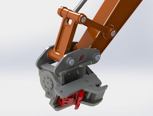


1 HELITILT OPERATIONS AND MAINTENANCE
2 JB ATTACHMENTS - WHEN ONLY THE BEST WILL DO! INCREASE PRODUCTIVITY PROFITABILITY VERSATILITY
3 CONTENTS 1.0 INTRODUCTION SAFETY INSTRUCTIONS STANDARDS INSTALLATION OPERATION AND ATTACHING MAINTENANCE HELITILT DRAWINGS / PARTS LIST MULTI-COUPLER DRAWINGS / PARTS LIST HELITILT DISASSEMBLY HELITILT ASSEMBLY HELITILT POST ASSEMBLY WARRANTY / CONTACT INFORMATION
4 INTRODUCTION
5 INTRODUCTION IMPORTANT NOTE: 1.0
6 INTRODUCTION CUSTOMER ACCEPTANCE AND WARRANTY REGISTRATION THE PURCHASER SHALL: 1.1
7 INTRODUCTION TO THE OWNER FOLLOW THE SAFETY INSTRUCTIONS: INFORMATION FOR THE USER: WARRANTY REGULATION: PLEASE COMPLETE THE CUSTOMER ACCEPTANCE AND WARRANTY REGISTRATION FORM LOCATED IN THIS MANUAL - FAILURE TO REGISTER MAY INVALIDATE YOUR WARRANTY CLAIM.

8 INTRODUCTION - OPERATION TECHNOLOGY and
9 INTRODUCTION - SAFETY GUIDLINES Cautionary Notices d t are t are not r or o or t Other Safety Guidelines and Precautions 1. to t was t t or w t was not t and o to as as damage to e o a 2. to t s done at e and may warranty. 3. s or a m as noted t or to o a e.g. d w a may wear It a t w are not Maximum Recommended Bucket Width for Use with PowerTilt PowerTilt Model Maximum Bucket Width n may e to t r and t added w o to 5. It t o to n and g at are damaged or a o 10 s
10 SAFETY INSTRUCTIONS SAFETY INSTRUCTIONS! WARNING! NOTE: 2.0

11 SAFETY INSTRUCTIONS Decal for inside cab. Part # JB Attachments

12 SAFETY INDICATION LABELS!! 2.2

13 SERIAL NUMBERS 2.3


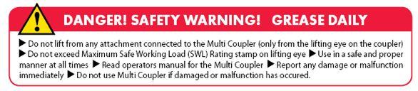
14 S.W.L - SAFE WORKING LOAD JB Attachments HeliTilt Lifting Eye Restrictions SAFE WORKING LOAD BADGE 2.4

15 S.W.L LIFTING EYE JB Attachments HeliTilt Lifting Procedures! WARNING: Use correct lifting connection! WARNING - VISUAL INSPECTION OF LIFTING EYE 2.5
16 STANDARDS Design, Installation, Maintenance and Operation STANDARDS AND OCCUPATIONAL SAFETY AND HEALTH GUIDELINES ASSOCIATED STANDARDS 3.0

17 STANDARDS NOTE: FOR JB ATTACHMENTS HELITILT SYSTEMS SUPPLIED TO OR MANUFACTURED IN COUNTRIES OTHER THAN NEW ZEALAND AND AUSTRALIA, THE RULES FOR PREVENTION OF ACCIDENTS AND SAFETY REGULATIONS FOR THE RESPECTIVE COUNTRY MUST BE STRICTLY ADHERED TO. 3.1
18 RISK ASSESMENT WORKING WITH HELITILT Location: Date: Ref no: People Affected YES NO N/A Expected Precautions YES NO N/A Personal Protective Equipment (PPE) Management Date 3.2
19 RISK ASSESMENT DAILY PRE-START CHECK SHEET M W D R I In Cab Hydraulic System PowerTilt with Multi-Coupler Base LUBRICATION Operator Signature Manager Signature 3.3
 ( 3-6) SAE BSPP 4 (1/4) 62 (1,060) 1.")
20 INSTALLATION HYDRAULIC REQUIREMENTS Tool Circuit Requirements for PT, PTA, PTB Series Model Sizes Displacement Required Oil Flow Port Connections* in³ (cm³ ) (525) gp m (liters/minute) ( 3-6) SAE BSPP 4 (1/4) 62 (1,060) (6-12) 4 (1/4) 89 (1,460 ) 3-5 (12-20 ) 6 (1/4) 118 (1,935 ) 6-7 (24-28 ) 6 (1/4) 159 (2,600 ) 6-8 (24-32 ) 6 (1/4) 215 (3,515 ) 8-11 (32-44 ) 6 (1/4) 277 (4,540 ) 9-13 (36-52 ) 6 (3/8) Hydraulic Hose and Tube S izing in (mm) 8 (10) 8 (10) 8 (10) 2 (12) 2 (12) 8 (16) 8 (16) e in (mm) 4 (6) 4 (6) 4 (6) 8 (10) 8 (10) 8 (10) 8 (10) Hydraulic Pressures e ( bar) ( bar) (40 bar) s to to o 4.0


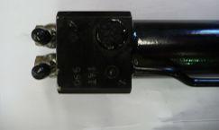
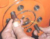
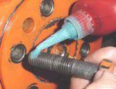
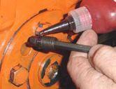
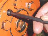
21 INSTALLATION FOR JB ATTACHMENTS FACTORY FITTED MULTI-COUPLER KIT ON EXCAVATOR STEP 1 FITTING HOSES TO CYLINDER! WARNING: Before removing the hydraulic cylinder from the Multi-Coupler base, it is best to remove the check valve because the check valve will hold the pressure inside the cylinder and cause resistance. Follow the steps below to relieve the internal pressure in the cylinder: Step One Step Two:! WARNING: Step Three: Step Four: - Check Valve Torque 30ft/lbs - 40Nm - Grub Screw Torque 15ft/lbs - 20Nm 4.1


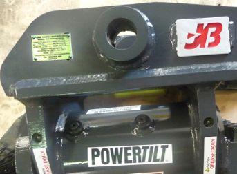
22 INSTALLATION FOR JB ATTACHMENTS FACTORY FITTED MULTI-COUPLER KIT ON EXCAVATOR STEP 2 STEP 3! CHECK PINS ARE ORIGINAL EQUIPMENT MANUFACTURER S PINS. 4.2


23 INSTALLATION FOR JB ATTACHMENTS FACTORY FITTED MULTI-COUPLER KIT ON EXCAVATOR STEP 4 HOSE POSITION 4.3


24 INSTALLATION FOR JB ATTACHMENTS FACTORY FITTED MULTI-COUPLER KIT ON EXCAVATOR STEP 4 HOSE POSITION 240mm! 4.4
25 INSTALLATION FOR JB ATTACHMENTS FACTORY FITTED MULTI-COUPLER KIT ON EXCAVATOR STEP 4 HOSE POSITION 2 2 ITEM QTY Part No. Description REVISION 1a

26 INSTALLATION CIRCUIT DIAGRAM! WARNING: 2 Index Code Part No. Description Qty
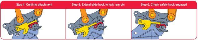
27 OPERATION AND ATTACHING MOUNTING AN ATTACHMENT TO HELITILT Connection Test REMOVING ATTACHMENT FROM HELITILT (STD BASE)


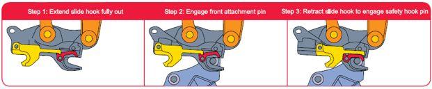
28 OPERATION AND ATTACHING OPERATION GUIDE FOR HELITILT MULTI-COUPLER BEFORE ATTACHMENT, ENSURE SAFETY LOCK IS OPEN Connection Test 5.1


29 OPERATION AND ATTACHING OPERATION GUIDE FOR POWERTILT MULTI-COUPLER ATTACHMENT OPERATION Connection Test. REMOVING ATTACHMENT FROM MULTI-COUPLER BASE


30 OPERATION AND ATTACHING CONNECTION TEST IMPORTANT WARNING!! DO NOT OPERATE MACHINE. 5.3


31 OPERATION AND ATTACHING CHECKING ATTACHMENTS AND BUCKETS!! 5.4


32 OPERATION CHECK ATTACHMENTS AND ATTACHING & BUCKETS CHECKING ATTACHMENTS AND BUCKETS CHECK PIN DIAMETER IS CORRECT image 1.0 CHECK PIN CENTRES ARE IN RANGE image
33 MAINTENANCE GENERAL MAINTENANCE!!!! WARNING - Maintenance Work DANGER - Hydraulic Fluid WARNING - PowerTilt Condition WARNING - Hose Arrangement Maintenance and Service Replacement Parts serial number DAILY CHECKS 6.0


34 MAINTENANCE WEEKLY CHECKS It is recommended that the following procedures are carried out at least once per week. THE MAINTENANCE AND REPAIR LOG FOR THE JB ATTACHMENTS HELITILT IS ON PAGE 6.7 Image 1.1 Image
35 MAINTENANCE MONTHLY CHECKS CIRCUIT DIAGRAM 1. Torque Wrench 2. Hydraulic Pressure 6.2
36 6.3 MAINTENANCE Problem Possible Cause Solution - -


37 500HR PREVENTATIVE MAINTENANCE CHECK Attachments Branch or authorised Service Centre immediately Check the clearance of the slide hook 4 6.4


38 500HR PREVENTATIVE MAINTENANCE CHECK 1 4mm 5mm 7mm 2 6.5
 Maximum Allowable Opening (mm) 30 25 35 30 40 34 45 36 50 40 55 45 60 50 60 51 65 54 65 54 70 59 80 67 80 67 90 77 90 71")
39 500HR PREVENTATIVE SAFETY-LATCH MAINTENANCE MANUAL INSPECTION CHECK MANUAL SAFETY- LATCH INSPECTION - wear-and-tear assessments. CHECK MOVEMENT OF SAFETY LATCH Maximum Opening Distance: image 3.0 Safe Allowable Variation Table PowerTilt Model Attachment Pin Diameter (mm) Maximum Allowable Opening (mm) ! 6.6
40 500HR PREVENTATIVE MAINTENANCE CHECK LIFTING EYE INSPECTION! Branch or authorised Service Centre immediately. 6.7
41 MAINTENANCE AND REPAIR LOG DATE FAULT / SERVICE DESCRIPTION MAINTENANCE / REPAIR EFFECTED BY WHOM 6.8
42 MAINTENANCE AND REPAIR LOG DATE FAULT / SERVICE DESCRIPTION MAINTENANCE / REPAIR EFFECTED BY WHOM 6.8
43 MAINTENANCE TORQUE SPECIFICATIONS Solenoid Valve 6.9
44 PTA ASSEMBLY DRAWING 7.0
45 PTB ASSEMBLY DRAWING 7.1
46 PT PISTON DRAWING * not r 7.2

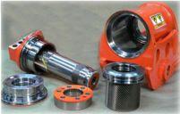
47 7.3 PT EXPLODED VIEW
48 TOOLS PARTS LIST PARTS Item Description Quantity R I or or C g 9 SEAL KIT Item Description Quantity nd C...1 or nd C R or R...0 or R...1 BEARING KIT Item Description Quantity or or or Order Your Spare and Replacement Parts Today or r an e ordered at or e or o and R arts and e r are on t ID as noted on

49 DRAW PIN DRAWING AND PARTS
50 MULTI-COUPLER PARTS LIST (Optional)

51 MULTI-COUPLER BASE PARTS DRAWING
52 CYLINDER PARTS LIST
53 CYLINDER PARTS DRAWING 8.4
54 DISASSEMBLY 9.0

55 DISASSEMBLY TOOLS REQUIRED e and r t e t are end t 3. t s 4. m s 8. w 9. or m t 10. mandre g w Making a Seal Tool t s a standard. 1. t end w a t 2. end o a v and t end to a r 3. o a edges o to a t may e d to own 9.1


56 DISASSEMBLY PRODUCT INSPECTION PRODUCT INSPECTION 1. r t and to o nto a. 3. a or. 2. r t standard or oot and oot remove t oot m. 4. and remove t r s 9.2


57 DISASSEMBLY 5. t two r set nto r set t r end and. 7. a or e standard or 6 6.I nsert nto r and. an t and t oot to s 9.3


58 DISASSEMBLY END CAP, LOCK RING AND CROSS PORT RELEIF VALVE REMOVAL 1. t on end o e to remove t ross. 3. t end t two and a ry. 4. Remove t t w e end or t 2. Remove t r m 9.4


59 DISASSEMBLY SHAFT REMOVAL Do not remove t at or t or. are to a m to t o n t r and s 1. Rotate t s rotate t e t t t end o to t s w t g v. 3. Remove t y and s g gear t o engagement w e d gear t t. 2. m on r g gear and m are on t o t and r gear. m may e n e root or t m are seen w t end o s s w gear t 9.5

60 DISASSEMBLY PISTON SLEEVE ASSEMBLY REMOVAL 1. r t y t t t r gear n to a 2. a r or and m t t to t.d. gear t gear t t 9.6


61 DISASSEMBLY SEAL AND BEARING REMOVAL 1. t to remove a wear and t w a end and. m may not wear on I.D..D. t s. 2. Remove t grease grease r and grease r. 9.7


62 DISASSEMBLY COMPONENT AND TIMING MARK INSPECTION 1. a m a t and dry w a. 2. a a wear g t and gear teet any w and any o s damage. 3. m on s and r g gear R w a anent m or s needed. 9.8


63 ASSEMBLY DRY ASSEMBLY SEAL AND BEARING INSTALLATION 10.0


64 ASSEMBLY SEAL AND BEARING INSTALLATION 2. o w w grease and on t o end. 5. and nto I.D. groove on e end. 3. w toward t 4. wear n e groove o end. 10.1


65 ASSEMBLY SEAL AND BEARING INSTALLATION Piston Seal and Bearing Installation 1. on some remove t one.d. and one I.D. and nearest to to do so may wear and. 3. wear on e I.D. 2. m on t.d. and I.D. t ote t are away o on s 10.2


66 ASSEMBLY SEAL AND BEARING INSTALLATION Shaft Seal and Bearing Installation 1. onto e. 3. w toward 4. wear. 2. o w w grease and onto e. 10.3


67 ASSEMBLY PISTON SLEEVE INSTALLATION 1 s y t and o to o damage. 3. t a t n t t r gear t 4. a or m and engage t nto e r gear t s t r gear. 2. s s t t t to t t C t t n r gear. 10.4


68 ASSEMBLY SHAFT SEAL AND BEARING INSTALLATION 1. t t o t r 3. t way t. 4. a to rotate t n t n. 2. Insert nto s a t t g on t t not to damage t I.D. w end o 10.5


69 ASSEMBLY END CAP AND LOCK RING INSTALLATION 1. end t end and w grease. 4. Remove t two and t t end a t w and end t to n 2. two t end t end onto t 5. r to t a t r and t end do not a t t end y no more one to a e. 3. a to rotate e and t t t w m w 10.6

70 ASSEMBLY END CAP AND LOCK RING INSTALLATION 6. an m t and remove r End Cap Torque Specifications Model Torque ft-lbs Nm Hydraulic pressure psi bar 10.7


71 ASSEMBLY CROSS PORT RELEIF VALVE INSTALLATION 1. w new and and t to Coat t t w 242 and t end o t and t to 225 or 305 Standard Pin-on Coupler I nstallation 1. r a t g and t two to t end and t. 10.8


72 ASSEMBLY STANDARD PIN-ON COUPLER INSTALLATION 2. a ry rotate t s e oot m s. 4. nto e oot s not a n 3. Remove t two and r. 5. onto. on to t oot 6. Coat t end o r and t o o end grease. 10.9


73 ASSEMBLY STANDARD PIN-ON COUPLER INSTALLATION 9. Coat t r t w and t t C on age 42. r onto 10. r two as 11.0

 ft-lbs Nm 44 2 76 4 190 5 370 15 640 20 1271 30 60 3 103 5 258 7 502 20 868 27 1723 41 Hex Head Bolt (grd 10.")
74 ASSEMBLY STANDARD PIN-ON COUPLER INSTALLATION t asteners to t on t C. Fastener Torque Specifications Torque Values for Port Plugs Plug Size Torque Value - Hollow Hex Head Plugs Torque Value - Hex Head Port Plugs ft-lbs Nm ft-lbs Nm Torque Values for Metric Fasteners Fastener Size M M M M M M Socket Head Bolt (grd 12.9) ft-lbs Nm Hex Head Bolt (grd 10.9) ft-lbs Nm Jam Nut (grd 12.9) ft-lbs Nm are 12.9 R g a re rade


75 POST ASSEMBLY TESTING AND GREASING Testing and Greasing t to a test or and t M s to movement. grease grease r and 1. s nto t s and t w e w grease. Testing the Carrier's Hydraulic System r to on age 15 need more C s D. 2. grease or orts on e end o and a grease t and t w r grease e t grease. It t r t to t and are t r a o e system s mandatory e any or 3. s and re-grease as D t r e 20 to 30 to and t degrees o 12.0
76 POST ASSEMBLY TESTING AND GREASING Testing for Internal Leakage 1. a test nto to ort t end o and e e.g. t or t oot or. not y e 2 at a v. 2. Remove and t to ort. 1 to or at 2 and and end. 3. t to ort and as n 1 4. or at 1 and a t m n and end as n 2 Testing the Cross Port Relief Valve ross vents t t at to 210 to 230 test t 1. a test nto to ort t t t end o and e.g. t or oot or. 2. to 2 and d t and t. 3. a to t end o vented to an. ross s set at and e 4. 1 e at w o r d vent at to 210 to at 2 t same 6. test does not meet t m e r test are e 12.1
77 WARRANTY INFORMATION JB ATTACHMENTS LTD Helac Corporation warrants its products to be free from defective material and factory workmanship for a period of one (1) year or 1000 service hours, whichever occurs first, for Helac Corporation approved applications, defined as medium duty service on the machine for which the Helac Attachment (PowerTilt or PowerGrip ) was originally designed and with cross port or work port relief valves installed according to Helac Corporation s recommendations. The warranty period shall begin when the Helac Attachment is first placed into service as documented by the return of the Warranty Registration Card to the factory. If the Registration Card is not returned, the warranty period will commence from the date the Helac Attachment was originally shipped from the factory. For products delivered from authorized dealer inventories, the warranty period shall commence no more than one (1) year from date of shipment from the factory. This warranty shall be voided as to any products which have been repaired, worked upon, or altered by persons not authorized by Helac Corporation, or which have been subject to misuse, misapplication, negligence, accident, overload, field alteration, severe use or service applications beyond what the Helac Attachment was designed to perform. In no event shall Helac Corporation be liable for any incidental or consequential damages or claims including, but not limited to, the application in which the product was placed, field travel, freight charges, oil samples, downtime, etc. Warranty related repair and/or replacement issues will be satisfied according to how the product was originally purchased: Direct Sales to End Users This warranty covers repair or replacement of product or parts, which under normal use and service disclose defective material and/or factory workmanship. Only repairs completed at the Helac factory or factory replacement (at Helac s option) will satisfy claims under this warranty. Products under warranty shall be returned to the Helac factory for evaluation and repair. The customer shall contact the Helac Warranty Department for a Return Authorization Number prior to shipping the product in question. The factory will not accept products returned without a Return Authorization Number. Transportation shall be prepaid by the purchaser. On receipt, Helac factory personnel will inspect the product for warrantable issue(s).upon warranty acceptance, Helac Corporation will repair the warranty issue(s)of the product at no cost to the customer and return the product freight prepaid. If it is determined that the issue(s)are not covered by the warranty, the product (repaired or not) will be returned COD to the customer. Sales Through Equipment Dealers This warranty covers labor at predetermined, fixed flat rates and repair or replacement of products or parts, which under normal use and service disclose defective material and factory workmanship. Claims under this warranty will be satisfied only by repair or replacement of the unit or any defective part there of. Products under warranty shall be returned to a factory authorized dealership location, transportation prepaid by the purchaser, for inspection by the dealer with factory consultation. Warranty repairs are only to be made at the selling dealer s location according to time maximums and at rates pre-established by Helac Corporation. Helac Corporation reserves the right to make changes in the design or construction of any of its products at any time without incurring any obligations to make changes or alterations to products previously sold. Helac Corporation reserves the right to alter this warranty and/or its terms at any time. This warranty is in lieu of all other and/or prior warranties, expressed or implied, and no other company or person is authorized to represent or assume for Helac Corporation any liability in connection with the sale of Helac Corporation products other than set forth herein. 13.0
78 SERVICE OFFERING TECHNICAL SUPPORT REPAIR SERVICE CONTACT US 13.1
79

80 JB Attachments Australia JB Attachments New Zealand
POWERTILT / MULTI-COUPLER
 POWERTILT / MULTI-COUPLER OPERATIONS AND MAINTENANCE MANUAL (P) PUBLISHED SEPTEMBER 2012 JB ATTACHMENTS - WHEN ONLY THE BEST WILL DO! INCREASE PRODUCTIVITY PROFITABILITY VERSATILITY CONTENTS 1.0 INTRODUCTION
Read this entire manual before operation begins.
 Read this entire manual before operation begins. Record below the following information which is located on the serial number data plate. Serial No. Model No. Date of Installation Contents Specifications.............
HELICAL HYDRAULIC ROTARY ACTUATORS
 T30-27 Service and Repair Manual HELICAL HYDRAULIC ROTARY ACTUATORS HA T30-27SM/12.10 INTRODUCTION Table of Contents Introduction Table of Contents... 2 Operation Technology... 3 General Safety Guidelines...
MULTI-COUPLER OPERATIONS AND MAINTENANCE MANUAL
 MULTI-COUPLER OPERATIONS AND MAINTENANCE MANUAL (P) PUBLISHED SEPTEMBER 2012 CONTENTS 1.0 INTRODUCTION 1.1 WARRANTY REGISTRATION 1.2 TO THE OWNER 2.0 SAFETY INSTRUCTIONS 2.1 JB ATTACHMENTS MULTI COUPLER
Read this entire manual before operation begins.
 Read this entire manual before operation begins. Record below the following information which is located on the serial number data plate. Serial No. Model No. Date of Installation Contents Specifications.............
Extreme Duty Grapple (Rock, Skeleton, Scrap & Tine) Operation and Maintenance Manual
 Operation and Maintenance Manual") Extreme Duty Grapple (Rock, Skeleton, Scrap & Tine) Operation and Maintenance Manual Revision Date: May 12, 2017 Skid Pro PO Box 982 Alexandria, MN 56308 Toll Free: 877-378-4642 www.skidpro.com TABLE OF
Extreme Duty Grapple (Rock, Skeleton, Scrap & Tine) Operation and Maintenance Manual Revision Date: May 12, 2017 Skid Pro PO Box 982 Alexandria, MN 56308 Toll Free: 877-378-4642 www.skidpro.com TABLE OF
OWNERS MANUAL HF4550 PREACHER CURL. Customer Service (800) (858) Fax (858) RECORD SERIAL NUMBER HERE
 (858) Fax (858) RECORD SERIAL NUMBER HERE") OWNERS MANUAL HF4550 PREACHER CURL Note: Both Serial Number and Model Number are Required when Ordering Parts RECORD SERIAL NUMBER HERE CATALOG NUMBER 0805-001 Customer Service (800) 548-5438 (858) 578-7676
OWNERS MANUAL HF4550 PREACHER CURL Note: Both Serial Number and Model Number are Required when Ordering Parts RECORD SERIAL NUMBER HERE CATALOG NUMBER 0805-001 Customer Service (800) 548-5438 (858) 578-7676
BOLT TORQUE SPECIFICATIONS STANDARD BOLTS:
 04-06 TP20124,Rev.3 ASSEMBLY OPERATION REPLACEMENT PARTS Mitsubishi Montero Limited Mitsubishi Montero XLS BOLT TORQUE SPECIFICATIONS STANDARD BOLTS: METRIC BOLTS: Size Grade Torque 5/16" 5 20 ft/lbs.
TILT BUCKET Twin Cylinder
 TILT BUCKET Twin Cylinder Imagery does not reflect actual product size OPERATION & MAINTENANCE MANUAL TBT2017A www.calibre.equipment 1 2 www.calibre.equipment TBT2017A CONTENTS INTRODUCTION Owner Information
OWNERS MANUAL HF PAIR VERTICAL DUMBBELL RACK. Customer Service (800) (858) Fax (858) RECORD SERIAL NUMBER HERE
 (858) Fax (858) RECORD SERIAL NUMBER HERE") OWNERS MANUAL HF4459 5 PAIR VERTICAL DUMBBELL RACK Note: Both Serial Number and Model Number are Required when Ordering Parts RECORD SERIAL NUMBER HERE CATALOG NUMBER 0605-000 Customer Service (800) 548-5438
OWNERS MANUAL HF4459 5 PAIR VERTICAL DUMBBELL RACK Note: Both Serial Number and Model Number are Required when Ordering Parts RECORD SERIAL NUMBER HERE CATALOG NUMBER 0605-000 Customer Service (800) 548-5438
ASM Maxi Poles. Instruction-Parts B Series. For the application of architectural paints and coatings.
 Instruction-Parts ASM Maxi Poles 312483B For the application of architectural paints and coatings. 3400 Series 4050 psi (27.92 MPa, 280 bar) Maximum Working Pressure Important Safety Instructions Read
OWNERS MANUAL HF
 OWNERS MANUAL HF4461-48 HORIZONTAL DUMBBELL RACK Note: Both Serial Number and Model Number are Required when Ordering Parts RECORD SERIAL NUMBER HERE CATALOG NUMBER 1005-000 Customer Service (800) 548-5438
Helical Hydraulic Rotary Actuators. L30 Series Service & Repair Manual
 Helical Hydraulic Rotary Actuators Table of Contents Table of Contents Introduction Table of Contents... 2 Product Introduction... 3 General Safety Guidelines... 4 Product Identification... 4 Theory of
Installation Instructions
 Equipment Required: Fastener Kit: F Wrenches: 15/16, 10 mm Drill Bits: 1/4 Other Tools: Drill, Reciprocating Saw 9464/9474 HIDE-A-GOOSE HITCH INSTALLATION All Fasteners Typical, Both Sides WARNING: Under
Installation Instructions
 Equipment Required: Fastener Kit: F Wrenches: 3/4, 15/16 Drill Bits: 1/4 Other Tools: Drill Short & Long Bed All Megacabs 9464/9474 HIDE-A-GOOSE HITCH INSTALLATION WARNING: Under no circumstances do we
Installation Instructions
 Equipment Required: Installation Instructions Fastener Kit: F Wrenches: 8mm, 13mm, 3/4, 15/16 Drill Bits: 1/4 Other Tools: Drill, Reciprocating Saw, File WARNING: Under no circumstances do we recommend
MODEL 5120 Tire Repair Station
 MODEL 5120 Tire Repair Station 00-0049 Installation, Operation & Repair Parts Information Branick Industries, Inc. 4245 Main Avenue P.O. Box 1937 Fargo, North Dakota 58103 REV01182017 P/N: 81-0058G CAUTION
CDS-JOHN BLUE COMPANY
 VRH-1000 HYDRAULIC VARIABLE RATE DRIVE AND MOUNT KIT PARTS AND INSTRUCTION MANUAL CDS-JOHN BLUE COMPANY DIVISION OF ADVANCED SYSTEMS TECHNOLOGY, INC. 290 Pinehurst Drive - Huntsville, Alabama 35806 P.O.
HSIV PLOW OPERATOR S MANUAL
 PLOW RWF INDUSTRIES 873 Devonshire Ave., Woodstock, Ontario N4S 8Z4 Tel: (519) 421-0036 Toll Free: 1-800-263-1060 Fax: (519) 421-0028 Email: parts@rwfbron.com JANUARY 2015 THE INFORMATION CONTAINED IN
CUSTOM CARRIERS. Crane Carrier Company Standard Warranty
 CUSTOM CARRIERS Crane Carrier Company Standard Warranty CRANE CARRIER COMPANY ("Manufacturer") warrants each new Crane Carrier sold by it or any of its authorized distributors to be free from defects in
Installation Instructions
 Equipment Required: Fastener Kit: F Wrenches: 3/4, 15/16 Drill Bits: 1/4 Other Tools: Drill WARNING: Under no circumstances do we recommend exceeding the towing vehicle manufacturers recommended vehicle
16K Revolution Service Kit Instructions 86016
 86016 Equipment Required: Wrenches: 15/16, 1 1/8, Torque Wrench, Rubber Mallet Included Service Kit Items: 1 Qty. (1) Wear Plate 2 Qty. (1) Pivot Bushing 3 Qty. (1) Bearing Cup 4 Qty. (1) Bearing 1 5 Qty.
MeTRic BolTs: 42 ft/lbs.
 Mazda B-Series Pickup 08-09 TP20067,Rev.3 BolT ToRQue specifications standard BolTs: size grade Torque 5/16 5 20 ft/lbs. 3/8 5 35 ft/lbs. 7/16 5 56 ft/lbs. 1/2 5 85 ft/lbs. MeTRic BolTs: size 8mm 10mm
Cardinal DETECTO. PORTABLE PLATFORM SCALES Digital Type Series 850F Owner s Manual
 Cardinal DETECTO PORTABLE PLATFORM SCALES Digital Type Series 850F Owner s Manual CARDINAL SCALE MFG. CO. PO BOX 151, WEBB CITY, MO 64870 0066-M176-O1 Rev H 10/06 417-673-4631 www.cardinalscale.com Printed
OWNERS MANUAL HF4263
 OWNERS MANUAL HF4263 ADJUSTABLE AB / BACK HYPER BENCH Note: Both Serial Number and Model Number are Required when Ordering Parts RECORD SERIAL NUMBER HERE CATALOG NUMBER 0805-000 Customer Service (800)
4-Ton Electric Log Splitter
 4-Ton Electric Log Splitter Questions: Support@Powrkraft.com PK65556 2 18ga. @ 20ft, 16ga. @ 50ft, 14 ga. @ 75ft. 12ga @ 100ft, 10ga @ 200ft These are minimum cord requirements. 13-16 Model Number 65556
Doing Our Best to Provide You the Best. Toyota Tacoma. Pin height: 17 Centers: 30-1/2. BOlT TORQuE specifications TP20190,Rev 7
 10-13 TP20190,Rev 7 Toyota Tacoma BOlT TORQuE specifications standard BOlTs: metric BOlTs: size grade Torque size Torque 5/16 5 20 ft/lbs. 8mm 22 ft/lbs. 3/8 5 35 ft/lbs. 10mm 42 ft/lbs. 7/16 5 56 ft/lbs.
Installation Instructions GOOSENECK MOUNTING KIT Toyota Tundra
 GOOSENECK MOUNTING KIT Toyota Tundra 446 Equipment Required: Fastener Kit: 446F Wrenches: 10mm, 1mm, /4, 7/8, 15/16 Drill Bits: 1/4 Other Tools: Drill WARNING: Do not store hitch ball upside down in head.
8" - 12" Hydraulic Steel Squeeze Off Tool
 8" - 12" Hydraulic Steel Squeeze Off Tool ECN 19130 C812S Hydraulic Steel Squeeze Off Tool for Steel Pipe Page 1 of 8 This Footage Tools C812S Steel Squeeze Off Tool is sold with one pump configuration
Operator s Manual. Nitro 1000 Nitro 1000X. Nitro 750 Nitro 750X. September REV0
 Operator s Manual Nitro 750 Nitro 750X Nitro 1000 Nitro 1000X September.27.2018REV0 Table of Contents Introduction...3 Safety.....4 Equipment Requirements......5 What You Have Received. 5 Serial Number...6
General Information - Inspection, Delivery, Service and Warranty Forms. Pre-Delivery Inspection Form Delivery Report
 Section 11 General Information - Inspection, Delivery, Service and Warranty Forms Pre-Delivery Inspection Form 132 Delivery Report 133 100-200 Hr Inspection Form 134 Service Report 135 TimberPro Warranty
Extreme Duty Grapple (Rock, Skeleton, Scrap & Tine) Operation and Maintenance Manual
 Operation and Maintenance Manual") Extreme Duty Grapple (Rock, Skeleton, Scrap & Tine) Operation and Maintenance Manual Revision Date: July 2017 Skid Pro PO Box 982 Alexandria, MN 56308 Toll Free: 877-378-4642 www.skidpro.com TABLE OF CONTENTS
Extreme Duty Grapple (Rock, Skeleton, Scrap & Tine) Operation and Maintenance Manual Revision Date: July 2017 Skid Pro PO Box 982 Alexandria, MN 56308 Toll Free: 877-378-4642 www.skidpro.com TABLE OF CONTENTS
3/8" 5 35 ft/lbs. 10mm 42 ft/lbs. 1/2" 5 85 ft/lbs. 14mm 95 ft/lbs.
 0-06 TP056,Rev. ASSEMBLY OPERATION REPLACEMENT PARTS Kia Rio BOLT TORQUE SPECIFICATIONS STANDARD BOLTS: METRIC BOLTS: Size Grade Torque Size Torque 5/6" 5 0 ft/lbs. 8mm ft/lbs. /8" 5 5 ft/lbs. 0mm 4 ft/lbs.
Doing Our Best to Provide You the Best. Centers-25-3/4 Pin Height PARTS LIST BOLT TORQUE SPECIFICATIONS TP20076,Rev.
 11-08 TP20076,Rev.5 Ford F-150 Pick-Up (4WD) Ford Expedition (4WD) BOLT TORQUE SPECIFICATIONS STANDARD BOLTS: METRIC BOLTS: Size Grade Torque Size Torque 5/16 5 20 ft/lbs. 8mm 22 ft/lbs. /8 5 5 ft/lbs.
Pressure Roller with 24-inch Fixed Extension - For application of architectural paints and coatings -
 Instructions Important Safety Instructions Read all warnings and instructions in this manual. Save these instructions. 311082D Pressure Roller with 24-inch Fixed Extension - For application of architectural
Product Parts Information
 Product s Information Second Generation Liftchain Industrial Air Hoist Models LC2A015S and LC2A030D (Dwg. MHP2659) Save These Instructions Form MHD56297 Edition 1 October 2004 71441307 2004 Ingersoll-Rand
BOLT TORQUE SPECIFICATIONS STANDARD BOLTS:
 10-05 TP2010,Rev. ASSEMBLY OPERATION REPLACEMENT PARTS Hyundai Accent BOLT TORQUE SPECIFICATIONS STANDARD BOLTS: METRIC BOLTS: Size Grade Torque Size Torque 5/16" 5 20 ft/lbs. 8mm 22 ft/lbs. /8" 5 5 ft/lbs.
42 ft/lbs PARTS LIST
 ASSEMBLY OPERATION REPLACEMENT PARTS Chevy Venture 04-06 TP20044,Rev.5 BOLT TORQUE SPECIFICATIONS STANDARD BOLTS: METRIC BOLTS: Size Grade Torque 5/16" 5 20 ft/lbs. 3/8" 5 35 ft/lbs. 7/16" 5 56 ft/lbs.
Innovation in Mobility. R1208 Six-Way Power Seat Base. Operator Manual. 03/25/02 32DSB01.A RICON CORPORATION All Rights Reserved
 Innovation in Mobility R1208 Six-Way Power Seat Base Operator Manual 03/25/02 32DSB01.A 92-2002 RICON CORPORATION All Rights Reserved Printed in the United States of America This RICON product must be
Installation manual. Rear traction bars. Ram Ram Part # Part # Important customer information:
 Installation manual Rear traction bars Ram 2500 2003-2013 Ram 3500 2003-2012 Part # 30991 sj12062011rev.01 Part # 30991 2003-2013 Ram 2500, 2003-2012 Ram 3500 Rear traction bars Part # Description Qty.
Doing Our Best to Provide You the Best. Honda CR-V Honda Element. BolT ToRQUE specifications
 6-11 TP20135,Rev.9 Honda CR-V Honda Element BolT ToRQUE specifications standard BolTs: METRiC BolTs: size Grade Torque size Torque 5/16 5 20 ft/lbs. 8mm 22 ft/lbs. 3/8 5 35 ft/lbs. 10mm 42 ft/lbs. 7/16
Installation Instructions
 Equipment Required: Fastener Kit: F Wrenches: 3/4, 15/16, 10mm, 18mm Drill Bits: 1/4 Other Tools: Drill, Reciprocating saw 9465/9475 HIDE-A-GOOSE HITCH INSTALLATION All Fasteners Typical, Both Sides WARNING:
HWP2/HWP3/HWP4 Hydraulic Submersible Pumps
 HWP2/HWP3/HWP4 Hydraulic Submersible Pumps 2-3 -4 Revised 6/10/2016 Prior to Operation We thank you for choosing a Rhino submersible pump. To ensure smooth operation and long-lasting performance of your
3/8" 5 35 ft/lbs. 10mm 42 ft/lbs. 1/2" 5 85 ft/lbs. 14mm 95 ft/lbs PARTS LIST NO. QTY. DESCRIPTION
 ASSEMBLY OPERATION REPLACEMENT PARTS Oldsmobile Alero 03-06 TP20068,Rev.5 BOLT TORQUE SPECIFICATIONS STANDARD BOLTS: METRIC BOLTS: Size Grade Torque Size Torque 5/16" 5 20 ft/lbs. 8mm 22 ft/lbs. 3/8" 5
metric BOlTS: 42 ft/lbs.
 Subaru Outback 11-13 TP20272,Rev.1 BOlT TORQuE SPECIfICATIONS STANDARD BOlTS: Size grade Torque 5/16 5 20 ft/lbs. 3/8 5 35 ft/lbs. 7/16 5 56 ft/lbs. 1/2 5 85 ft/lbs. metric BOlTS: Size 8mm 10mm 12mm 14mm
Tiller Lock Assembly
 2 1 4 1 2 4 1 2 4 1 7 6 7 8 Positioning Pin Assembly 1 Positioning Pin 2 Spring Black Knob 5 4 1 2 2 1 Tiller Lock Assembly 1 2 4 Threaded Rod Rotating Rod Spring Flat Washer 5 6 7 8 C Type Plastic Washer
76" H x 36" W x 27" D. 80" H x 38" W x 48" D. Maximum 150 psi Standard shop air (8 100 psi)
") Part# 26BPAC - Pack-Master Air Compactor The Pack-Master Air is the best value for a pneumatic waste compactor. With the Pack-Master Air, you can effortlessly compact material in a 30 or 55 gallon drum
Part# 26BPAC - Pack-Master Air Compactor The Pack-Master Air is the best value for a pneumatic waste compactor. With the Pack-Master Air, you can effortlessly compact material in a 30 or 55 gallon drum
SHEYENNE TELE-BOOM OWNERS MANUAL OPERATOR INSTRUCTIONS PARTS BOOK
 SHEYENNE TELE-BOOM OWNERS MANUAL OPERATOR INSTRUCTIONS PARTS BOOK 701 Lenham Ave. SW PO Box 647 Cooperstown ND 58425 1-800-797-1883 701-797-2700 * 701-797-2584 Fax www.sheyennemfg.com TABLE OF CONTENTS
5 th Airborne Sidewinder Service Kit Instructions 94316
 94316 Equipment Required: Wrenches: 15/16, Torque Wrench, Rubber Mallet 3 4 5 2 Included Service Kit Items: 1 Qty. (1) Wear Plate 2 Qty. (1) Wear Bushing 3 Qty. (1) Wear Disc 4 Qty. (4) 5/8-11x2 GRD8 Bolt
Installation Instructions GOOSENECK MOUNTING KIT Chevrolet/GMC 1500/2500/3500 All except 4-door Crew-Cab
 GOOSENECK MOUNTING KIT Equipment Required: Fastener Kit: F Wrenches: 3/4, 7/8, 15/16 Drill Bits: 1/4 Other Tools: Drill WARNING: Under no circumstances do we recommend exceeding the towing vehicle manufacturers
Doing Our Best to Provide You the Best. Pontiac Transport Pontiac Montana
 Pontiac Transport Pontiac Montana 07-09 TP20043,Rev.5 BolT ToRQue specifications standard BolTs: MeTRic BolTs: size grade Torque size Torque 5/16 5 20 ft/lbs. 8mm 22 ft/lbs. 3/8 5 35 ft/lbs. 10mm 42 ft/lbs.
THUMB OPERATIONS AND MAINTENANCE MANUAL
 THUMB OPERATIONS AND MAINTENANCE MANUAL INTRODUCTION Thanks for choosing from JB Attachments range of earthmoving products. The contents of this manual should be thoroughly read and understood by the operators
metric BOlTS: 42 ft/lbs.
 Nissan Sentra 04-10 TP20276,Rev.0 Pin height - 12-1/2 Centers - 20-1/2 BOlT TORQuE SPECIfICATIONS STANDARD BOlTS: Size grade Torque 5/16 5 20 ft/lbs. 3/8 5 35 ft/lbs. 7/16 5 56 ft/lbs. 1/2 5 85 ft/lbs.
General Information - Inspection, Delivery, Service and Warranty Forms. Delivery and Inspection Information
 Section 1.1 General Information - Inspection, Delivery, Service and Warranty Forms Delivery and Inspection Information... 1.3.2 Pre-Delivery Inspection Form... 1.3.3 Delivery Report... 1.3.5 100-200 Hr
Installation Instructions
 Equipment Required: Fastener Kit: F Wrenches: 3/4, 15/16 Drill Bits: 1/4 Other Tools: Drill, Reciprocating saw WARNING: Under no circumstances do we recommend exceeding the towing vehicle manufacturers
Deluxe Hitch 3-Bike Rack Instructions for Part # BC-3581
 General Guidelines Deluxe Hitch 3-Bike Rack Instructions for Part # BC-3581 It is the user s responsibility to read and follow all instructions. Keep these instructions with the product at all times and
16K and 19K Sidewinder TM Service Kit Instructions 86005
 86005 Equipment Required: Wrenches: 15/16, 1 1/8, Torque Wrench, Rubber Mallet Included Service Kit Items: 1 Qty. (1) Wear Plate 2 Qty. (6) 5/8 Conical Washer 3 Qty. (2) Wedge Bolt, 5/8-11 X 1 3/4 GRD
MODEL 7400 STRUT SPRING COMPRESSOR
 MODEL 7400 STRUT SPRING COMPRESSOR Installation, Operation & Repair Parts Information Branick Industries, Inc. 4245 Main Avenue P.O. Box 1937 Fargo, North Dakota 58103 REV112712 P/N: 81-0103A TABLE OF
MODEL 7600 STRUT SPRING COMPRESSOR
 MODEL 7600 STRUT SPRING COMPRESSOR Installation, Operation & Repair Parts Information Branick Industries, Inc. 4245 Main Avenue P.O. Box 1937 Fargo, North Dakota 58103 REV6162014 P/N: 81-0246 TABLE OF
PARTS MANUAL 360 ROTATOR MODEL NUMBER R Industrial Way Lebanon, Oregon FORKLIFT ATTACHMENTS
 PARTS MANUAL 0 ROTATOR MODEL NUMBER R 8 Industrial Way Lebanon, Oregon 97.800.7. Class 0 Rotator R.000.0. VCG. HCG Specifications 7.0 Lost Load TABLE Column Column CAPACITY 000 LBS @ " LOAD CENTER MOUNTING
Universal Bevel Drives Service Manual
 Engineering Service Bulletin #SB241202 Universal Bevel Drives Service Manual Cautions Following are some general cautions. All personnel shall use safe and sound practices and take all necessary precautionary
Doing Our Best to Provide You the Best. GMC Acadia & Buick Enclave. Pin Height: 18 Centers: 24. BOlT TORQuE SPECIfICATIONS TP20302,Rev.
 GMC Acadia & Buick Enclave 12-13 TP20302,Rev.1 BOlT TORQuE SPECIfICATIONS STANDARD BOlTS: Size Grade Torque 5/16 5 20 ft/lbs. 3/8 5 35 ft/lbs. 7/16 5 56 ft/lbs. 1/2 5 85 ft/lbs. METRIC BOlTS: Size 8mm
Installation manual. Rear ladder bars. Chevy/GMC 2500/3500 HD. Part # Part # Important customer information:
 Installation manual 2011-2018 Chevy/GMC 2500/3500 HD Part # 10892 sj07272011rev.01 Part # 10892 2011-2018 Chevy/GMC 2500/3500 HD Part # Description Qty. 10892-01 Rear ladder bar brackets 2 10892-02 Front
LUBRICATOR GUN INSTRUCTIONS-PARTS LIST. 10,000 psi (700 bar) Maximum Delivery Pressure. Detachable-type
 Maximum Delivery Pressure. Detachable-type") INSTRUCTIONS-PARTS LIST 306 460 INSTRUCTIONS This manual contains important warnings and information. READ AND KEEP FOR REFERENCE. Rev. E Supercedes D Detachable-type LUBRICATOR GUN 10,000 psi (700 bar)
INSTRUCTIONS-PARTS LIST 306 460 INSTRUCTIONS This manual contains important warnings and information. READ AND KEEP FOR REFERENCE. Rev. E Supercedes D Detachable-type LUBRICATOR GUN 10,000 psi (700 bar)
Installation / Owners Manual
 DEALER/INSTALLER: (1) Provide this Manual to end user END USER: Part Number: 94621 94622* *Packaged for Individual sale. (1) Read and follow this Manual for Reese Installation. (2) Save this Manual for
Installation Instructions
 Equipment Required: Fastener Kit: F Wrenches: 3/4, 15/16, 13mm Drill Bits: 1/4, some older models a 1/2 Other Tools: Drill, Saber Saw 5/8 Fasteners From Hitch Fastener Kit Installation Instructions GOOSENECK
Operating Manual. 2012, 2024, and 2026 Soil Sampler th AVE N Fargo, ND Phone: (701) Web: farmqa.com
 Web: farmqa.com") Operating Manual 2012, 2024, and 2026 Soil Sampler 2800 7th AVE N Fargo, ND 58102 Phone: (701) 237-2167 Web: farmqa.com AMITY TECHNOLOGY, LLC PRODUCT WARRANTY Amity Technology, LLC warrants to the original
Operating Manual 2012, 2024, and 2026 Soil Sampler 2800 7th AVE N Fargo, ND 58102 Phone: (701) 237-2167 Web: farmqa.com AMITY TECHNOLOGY, LLC PRODUCT WARRANTY Amity Technology, LLC warrants to the original
Installation manual. 3 suspension system Toyota Tacoma. 4x4 and 2WD PreRunner. Part # Part # Important customer information:
 Installation manual 3 suspension system 2005 2018 Toyota Tacoma 4x4 and 2WD PreRunner Part # 52907 sj11112011rev.05 Part # 52907 2005-2018 Toyota Tacoma 4x4 and 2WD PreRunner 3 suspension system Part #
INSTALLATION, INSTRUCTION AND SERVICE MANUAL
 INSTALLATION, INSTRUCTION AND SERVICE MANUAL Actuator/Brake/Trailer Dealer Please provide to consumer. Consumer Read and follow instructions. Keep with trailer for reference. Page 1 of 7 1. Introduction...
metric BOlTs: 42 ft/lbs.
 08-09 TP20059,Rev.5 Dodge Caravan Plymouth Voyager BOlT TORQuE specifications standard BOlTs: size grade Torque 5/6 5 20 ft/lbs. /8 5 5 ft/lbs. 7/6 5 56 ft/lbs. /2 5 85 ft/lbs. metric BOlTs: size 8mm 0mm
POWERTILT SWING ATTACHMENT
 POWERTILT Instruction, Service and Repair Manual PT, PTA and PTB Series Optional PowerTilt Pin Grab Coupler POWERTILT SWING ATTACHMENT HE PTSM/12.16 INTRODUCTION Table of Contents Introduction Table of
Read this entire manual before operation begins.
 Read this entire manual before operation begins. Record below the following information which is located on the serial number data plate. Serial No. Model No. Date of Installation Contents Specifications.............
MODEL EF Full Circle Tire Spreader
 MODEL EF Full Circle Tire Spreader Installation, Operation & Repair Parts Information Branick Industries, Inc. 4245 Main Avenue P.O. Box 1937 Fargo, North Dakota 58103 REV. 062917 P/N: 81-0050C CAUTION
HR-20P Pneumatically Controlled Pressure Regulator
 HR-20P Pneumatically Controlled Pressure Regulator Instruction and Service Manual Hydroplex Corporation 230 West Gloria Switch Rd. Lafayette, LA 70507 337-233-0626 www.hydroplexpumps.com I. General Instructions
SUNDOWN Operation. & Parts Manual. for Box Blade Models BB15-48, 60 BB20-48, 60, 72 BB30-60, 72, 84, & 96
 SUNDOWN Operation & Parts Manual for Box Blade Models BB15-48, 60 BB20-48, 60, 72 BB30-60, 72, 84, & 96 Operations and Parts Manual Table of Contents Section Page Table of Contents 2 Retail Customer Responsibility
OWNERS MANUAL HF4261
 OWNERS MANUAL HF4261 ADJUSTABLE AB BENCH Note: Both Serial Number and Model Number are Required when Ordering Parts RECORD SERIAL NUMBER HERE CATALOG NUMBER 0905-000 Customer Service (800) 548-5438 (858)
Helical Hydraulic Rotary Actuators. T20 Series Service & Repair Manual
 Helical Hydraulic Rotary Actuators Table of Contents Table of Contents Introduction Table of Contents... 2 Product Overview... 3 Operation Technology... 4 General Safety Guidelines... 5 Product Identification...
Miller Compact Manual Quick Couplers
 Miller: Issue 2 Miller Compact Manual Quick Couplers For Mini Excavators (1 to 10 tonne) and Backhoe Loaders Installation Guide and Operator s Instructions IMPORTANT Keep this manual with the machine at
Model D Spray Gun. Parts Identification Manual 2943J-ID. "Success through Unity" June 17, 2003 Issue 2 GUSMER CORPORATION
 "Success through Unity" Model D Spray Gun Parts Identification Manual 2943J-ID June 17, 2003 Issue 2 GUSMER CORPORATION A Subsidiary of Gusmer Machinery Group, Inc. One Gusmer Drive Lakewood, New Jersey,
AUTOMATIC SUBMERSIBLE UTILITY PUMP
 AUTOMATIC SUBMERSIBLE UTILITY PUMP Zoeller is a registered trademark of Zoeller Co. All Rights Reserved. MODEL #1043-0006 Español p. 9 ATTACH YOUR RECEIPT HERE Serial Number Purchase Date Questions, problems,
Doing Our Best to Provide You the Best. Instructions for 1997 & 1998 Models start on page 4. BOLT TORQuE specifications.
 Jeep Cherokee Jeep Wagoneer Jeep Wagoneer LTD Jeep Comanche Pick-up 12-12 TP20010,Rev.9 Centers-24 Pin Height-16 BOLT TORQuE specifications standard BOLTs: size grade Torque 5/16 5 20 ft/lbs. 3/8 5 35
Installation Instructions
 Equipment Required: Fastener Kit: F Wrenches: 15/16, 15/16 Crowfoot Adaptor Drill Bits: 1/4 Other Tools: Drill, Reciprocating saw Optional, Raise Bed: 18mm socket, 15 extension As an option you can loosen
PART NUMBER: F-706RLSS REVOLUTION LIFT: SLING-SEAT OPTION
 PART NUMBER: F-706RLSS REVOLUTION LIFT: SLING-SEAT OPTION 500 LB. [227 kg] MAXIMUM CAPACITY MANDATORY LEAVE THIS MANUAL WITH LIFT OWNER - WARNING- IMPORTANT SAFETY INSTRUCTIONS 1. READ AND FOLLOW ALL INSTRUCTIONS.
Complete Raised Rail Roof Rack System SR1098 SR1099
 Complete Raised Rail Roof Rack System SR1098 SR1099 7 kg/15 lbs xx kg xx lbs Max. 68 kg/150 lbs Instructions Max load capacity 68 kg/150 lbs Before you begin, please read the assembly instructions carefully.
OPERATORS MANUAL SAFETY & WARRANTY SECTION
 OPERATORS MANUAL SAFETY & WARRANTY SECTION KMW Ltd. 198 N. Hwy 281 Great Bend, Kansas 67530 800 445-7388 Fax 620 793-6737 ïïïkâãïäç~çéêëkåçã SAFETY FIRST This symbol, the industry s Safety Alert Symbol,
STRUT SPRING COMPRESSOR
 OWNER S MANUAL PRODUCT CODE: 1221T STRUT SPRING COMPRESSOR Capacity Stroke Spring Coil Spring Spring Coil Net Weight (Maximum) Thickness Length Diameter 1,000kg 330mm 10-18mm 210-570mm 100-158mm 36kg Made
Pneumatic Cylinder 14 Bore X 22 Stroke Part No. R (Formerly P )
") Pneumatic Cylinder 14 Bore X 22 Stroke Part No. R434001268 (Formerly P -193419-00003) Service Information INSTALLATION Before installing this cylinder, all air lines in the system should be blown clean
Pneumatic Cylinder 14 Bore X 22 Stroke Part No. R434001268 (Formerly P -193419-00003) Service Information INSTALLATION Before installing this cylinder, all air lines in the system should be blown clean
Doing Our Best to Provide You the Best. VW Golf, GTi, Jetta PaRTs list. BOlT TORQuE specifications TP20103,Rev.4
 10-09 TP20103,Rev.4 VW Golf, GTi, Jetta BOlT TORQuE specifications standard BOlTs: metric BOlTs: size Grade Torque size Torque 5/16 5 20 ft/lbs. 8mm 22 ft/lbs. 3/8 5 35 ft/lbs. 10mm 42 ft/lbs. 7/16 5 56
Installation manual. 3 suspension system Toyota Tacoma. Part # Part # Important customer information: Toyota Tacoma
 Installation manual 3 suspension system 2005 2008 Toyota Tacoma Part # 52907 sj111607rev.02 Part # 52907 2005-2008 Toyota Tacoma 3 suspension system Part # Description Qty. 52907-01 Pre-load spacer 2 52907-02
Installation manual. 1.5 front leveling kit. Nissan Titan. Part # Part # Important customer information: Nissan Titan
 Installation manual 1.5 front leveling kit 2004-2015 Nissan Titan Part # 52008 sj071408rev.01 Part # 52008 2004-2015 Nissan Titan 1.5 front leveling kit Part # Description Qty. 52008-01 Front strut spacers
Series CP200. Triplex Ceramic Plunger Pump Operating Instructions/ Repair and Service Manual. For Models: CP218 CP219 CP220 CP230
 Series CP200 Triplex Ceramic Plunger Pump Operating Instructions/ Repair and Service Manual For Models: CP218 CP219 CP220 CP230 Updated 10/02 Contents: Installation Instructions: page 2 Pump Specifications:
Part Number Mini Linear Lift Assembly Installation & Operator s Instruction Manual
 Part Number 39644 Mini Linear Lift Assembly Installation & Operator s Instruction Manual April 1999 MV1505C Chore-Time Warranty Mini Linear Lift Assembly Manual Chore-Time Warranty Chore-Time Equipment
General Guidelines. Instructions for Part # SC-SWING-AWAY-V2. Safety
 Instructions for Part # SC-SWING-AWAY-V2 General Guidelines It is the user s responsibility to read and follow all instructions. Keep these instructions with the product at all times and review before
MOVE ON TO THE REAR BAR INSTALLATION
 22410 STREET SWAY BAR SET 2001-UP LEXUS IS300 Thank you for your purchase from our line of Lexus parts. Please call us at (877) 4NO-ROLL if you have any questions regarding the service or installation
Motor Mounting Kits. Instructions J EN. 16C487 Motor Coupler Kit includes 2.25 in. (57.2 mm) key For NEMA 182/184 TC Frame ATEX Electric Motors
 key For NEMA 182/184 TC Frame ATEX Electric Motors") Instructions Motor Mounting Kits 31160J EN To install electric motors on E-Flo 4-Ball Piston Pumps. For professional use only. (Kits do not include motors.) 16C487 Motor Coupler Kit includes 2.2 in. (7.2
Instructions Motor Mounting Kits 31160J EN To install electric motors on E-Flo 4-Ball Piston Pumps. For professional use only. (Kits do not include motors.) 16C487 Motor Coupler Kit includes 2.2 in. (7.2
Installation manual. Toyota Tundra 4WD & 2WD. 2.5 Suspension kit. Part # Part # Important customer information:
 Installation manual 2007-2016 Toyota Tundra 4WD & 2WD 2.5 Suspension kit Part # 53070 sj11082011rev.03 Part # 53070 2007-2016 Toyota Tundra 4WD & 2WD 2.5 Suspension kit Part # Description Qty. 53070-01
Installation Instructions
 Installation Instructions IMPORTANT! READ AND UNDERSTAND THESE INSTRUCTIONS FOR SAFETY, INSTALLATION, OPERATION, AND MAINTENANCE. SAVE ALL INSTRUCTIONS FOR FUTURE REFERENCE. Tested. Trusted. Guaranteed.
INSTALLATION INSTRUCTIONS AND OWNER S MANUAL
 INSTALLATION INSTRUCTIONS AND OWNER S MANUAL Thank you for purchasing ADARAC Truck Bed Rack. Agri-Cover, Inc. proudly manufactured this product using superior quality materials and workmanship. With proper
Read this entire manual before operation begins.
 Read this entire manual before operation begins. Record below the following information which is located on the serial number data plate. Serial No. Model No. Date of Installation Contents Specifications.............
Installation Instructions
 Equipment Required: Installation Instructions Fastener Kit: F Wrenches: 15/16, 10 mm Drill Bits: 1/4 Other Tools: Drill, Reciprocating Saw 9464/9474 HIDE-A-GOOSE HITCH All Fasteners Typical, Both Sides