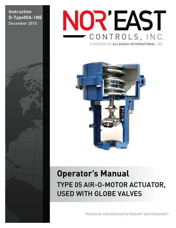
Nor East. Instructions. Safety Messages. Inspection. Parts Nor East Controls. Service. Type 05 Air-O-Motor Actuator Used With Globe Valves
|
|
|
- Scarlett Carson
- 5 years ago
- Views:
Transcription
1
2 Instructions Safety Messages These instructions are intended for personnel who are responsible for installation, operation and maintenance of your Nor East Controls Actuator. All safety messages in the instructions are flagged with the word Caution, Warning or Danger. These messages must be followed exactly to avoid equipment damage, personal injury or death. Safety label(s) on the product indicate hazards that can cause equipment damage, personal injury or death. If a safety label becomes difficult to see or read, or if a label has been removed, please contact Nor East Controls for replacement label(s). Personnel involved in the installation or maintenance of valves should be constantly alert to potential emission of pipeline material and take appropriate safety precautions. Always wear suitable protection when dealing with hazardous pipeline materials. Handle valves, which have been removed from service with suitable protection for any potential pipeline material in the valve. Inspection Parts Nor East Controls Service Your Nor East Controls Actuator has been packaged to provide protection during shipment. Carefully inspect the unit for damage upon arrival and file a claim with the carrier if damage is apparent. Order parts from your local sales representative, or directly from Nor East Controls, as listed on the back cover. Recommended spare parts are listed on the assembly drawing. These parts should be stocked to minimize downtime. Nor East Controls service personnel are available to install, maintain and repair all Nor East Controls products. Nor East Controls also offers customized training programs and consultation services. For more information, contact your local Nor East Controls sales representative or visit our website at East Controls.com. D-Type05A 2009 Nor East Controls
3 Table of Contents Description Action Installation Thrust Model Lever Model Both Models Assembling Lever for Direct Action Changing to Reverse Lever Action Parts Identification Preventive Maintenance Diaphragm Replacement Gradutrol Positioner Adjustment December 2010 Page 1 D-Type05A
4 Description The Type 05 Air-O-Motor actuator is a compact pneumatic power device which converts a signal pressure into mechanical motion. The force developed can exert either a straight upward or downward thrust, or operate a reversible lever working on a pivot. Travel is proportional to the amount of air pressure. Two models are available Thrust or Lever. Thrust models provide more force, but less travel. Lever models provide more travel, but less force. Refer to Tables A, C and C.. Action Thrust models are direct acting which means the actuator stem moves downward with increasing air pressure. For lever models, the action can be either direct or reverse with increasing air pressure depending upon the lever mounting arrangement. See Figure 1. Figure 1 Lever Action, Direct and Reverse Table A Travel - mm (in.) Thrust Model 38 mm (1.50) Lever Model Lever Hole A B C D E F G H 82(3.24) 110(4.32) 137(5.40) 165(6.48) 192(7.57) 219(8.63) 247(9.72) 274(10.80) D-Type05A Page 2 December 2010
5 Table B: Force kg (lbs) Spring Range kpa (psig) Full Travel (3-15) (5-13) Full Travel Full Travel Zero Travel (7-18) (3-15) (5-13) (7-18) Air Pressure kpa (psig) 124 (18) 124 (18) 172 (25) 241 (35) 172 (25) 241 (35) Thrust Model kg (lbs) 54 (120) 91 (200) 218 (480) 399 (880) 127 (280) 308 (680) 54 (120) 91 (200) 127 (280) Lever Model Full Travel Zero Travel Lever Hole A 25 (55) 41 (90) 100 (220) 184 (405) 59 (130) 141 (310) 25 (55) 41 (90) 59 (130) B 19 (41) 32 (70) 75 (165) 138 (305) 43 (95) 107 (235) 19 (41) 32 (70) 43 (95) C 15 (33) 25 (55) 59 (130) 111 (245) 36 (80) 86 (190) 15 (33) 25 (55) 36 (80) D 13 (28) E 11 (24) F 10 (21) 20 (45) 50 (110) 91 (200) 29 (65) 70 (155) 13 (28) 20 (45) 29 (65) 18 (40) 43 (95) 79 (175) 25 (55) 61 (135) 11 (24) 18 (40) 25 (55) 16 (35) 36 (80) 68 (150) 23 (50) 52 (115) 10 (21) 16 (35) 23 (50) G 8 (18) 14 (30) 34 (75) 61 (135) 20 (45) 48 (105) 8 (18) 14 (30) 20 (45) H 7 (16) 11 (25) 29 (65) 54 (120) 18 (40) 43 (95) 7 (16) 11 (25) 18 (40) NOTE: For rotary-actuated final control elements, determine available torque using brochure PIB-16, Air-O-Motor Actuator Size Selection. December 2010 Page 3 D-Type05A
6 Installation Thrust Model This unit is usually shipped completely assembled. The base plate has four 9/16 (14 mm) diameter mounting holes. The clevis is screwed onto the actuator stem and locked with a set screw. To attach the clevis to the valve linkage, remove the pin. For wall mounting, a 90 bracket is supplied with mounting holes to match the base plate. Lever Model This unit is usually shipped with lever unassembled (see Assembling Lever for Direct Action). If reverse action is desired, see Changing to Reverse Lever Action. The base plate has four 9/16 (14 mm) diameter mounting holes. Attach valve linkage, etc. to proper lever hole (hole is 3/8 (10 mm) diameter). For wall mounting, a 90 bracket is supplied with mounting holes to match the base plate. Both Models Air connections for the actuator are 1/4 NPT. Gradutrol positioner connections are 1/8 NPT. 1/4" ID tubing and fittings are recommended for the rest of the line. Connect instrument air signal to P port and regulated air supply (max 25 psig) to M port, when installing a Gradutrol positioner. Assembling Lever for Direct Action 1. Loosen two set screws in clevis and one in pivot point. 2. Remove pins. 3. Turn clevis, insert lever and insert clevis pin. 4. Line up lever in pivot point and insert pivot pin. 5. Tighten set screws in clevis and pivot point. Figure 2 Cutaway View of Lever Secured in Pivot Notch D-Type05A Page 4 December 2010
7 Installation (continued) Nor East Changing to Reverse Lever Action 1. Unscrew set screw in pivot point. 2. Unscrew and remove pivot point. See Figure 3. Figure 3 Remove Pivot Point 3. Lift lever from pivot notch and place in position shown in Figure 4. It may be necessary to loosen set screw in top of clevis. Figure 4 Lever Position 4. Remove lever set screw and drive out clevis pin with punch. 5. Remove lever from clevis and yoke. 6. Turn lever 180 and insert through yoke. See Figure 5. Figure 5 Lever in Yoke 7. Drive clevis pin in until near end is flush and other end protrudes 1/8 (0.9 mm). See Figure Replace set screws. Figure 6 Lever in Yoke December 2010 Page 5 D-Type05A
8 Parts Identification Figure 7 Thrust Model (Direct Acting) Figure 8 Lever Model (Direct Acting) D-Type05A Page 6 December 2010


9 Preventive Maintenance Diaphragm Replacement Gradutrol Positioner Adjustment The most important part of preventive maintenance is a visual inspection at regular intervals. A suggested inspection folloes: 1. All air connections are tight. 2. Diaphragm case bolts are tight. 3. Stem is locked into stem locking slide. 4. Actuator is firmly fastened to yoke or base plate. 5. Actuator set screws are tight. 6. Clevis pin is fully engaged in clevis. Direct Acting Actuator 1. Alternately loosen diaphragm case bolts. 2. Remove the diaphragm case and replace the diaphragm. 3. Replace diaphragm case and alternately tighten case bolts. NOTE: If the actuator has a top-mounted Gradutrol positioner, remove the positioner s spring seat from the old diaphragm and glue it to the new diaphragm with a light coat of pliobond, Ambroid, 3M brand EC847 or other suitable bonding glue. Assemble the actuator and screw the positioner out of the upper case. Place the spring seat onto the diaphragm, locating it in center of the positioner mounting hole. Range adjustment is changed by the six adjustment screws (1) and (2). Refer to Figures 7 and 8. The start point is adjusted by turning the knob on top of the positioner. The graduations of the external calibration scale on the knob represent values within the different ranges. Refer to Table C for adjustment. All positioners are factory set for 3 psi start point and 12 psi range. Table C: Range and Start Point Adjustments Operating Range 12 psi 6 psi 3.6 psi Range djustment All screws 1 and 2 tightened Three screws 1 backed off to friction stop All screws 1 and 2 backed off to friction stop Start Point Adjustment One graduation of scale on start point adjustment knob represents a start point change of 1 psi. One complete turn of the start point adjustment knob repsresents a start point change of 10 psi. One graduation of scale on start point adjustment knob represents a start point change of 0.5 psi. Two complete turn of the start point adjustment knob repsresents a start point change of 10 psi. One graduation of scale on start point adjustment knob represents a start point change of 0.3 psi. Three complete turn of the start point adjustment knob repsresents a start point change of 9 psi. December 2010 Page 7 D-Type05A
10 Guarantee Products, auxiliaries and parts thereof, of Nor East Controls manufacture, are guaranteed for a period of one year from the date of shipment against defective workmanship and material only, when properly installed, operated and serviced in accordance with Nor East Controls recommendations. Replacement for items of Nor East Controls manufacture will be made free of charge if proved to be defective within such time. No claim for special or consequential damages, transportation, or labor shall be allowed. Purchaser shall be solely responsible for determining suitability for use and in no event shall Nor East Controls be liable in this respect. Equipment or parts manufactured by others but furnished by Nor East Controls will be repaired or replaced, only to the extent provided in the original manufacturer s warranty to Nor East Controls. Nor East Controls does not guarantee resistance to corrosion, erosion, abrasion or other sources of failure, nor does Nor East Controls guarantee a minimum length of service. Failure of the purchaser to give prompt written notice of any alleged defect under this guarantee forthwith upon its discovery, or use and possession thereof after an attempt has been made and completed by someone other than Nor East Controls or an authorized representative to remedy defects therein, or failure to return products or parts for replacement as herein provided, of failure to install, operate, and maintain said products or parts according to instructions provided by Nor East Controls, of failure to pay the entire contract price when due, shall be a waiver of all rights under these representations. The foregoing guarantee shall be null and void, if, after shipment from our factory, the item is modified in any way or component of another manufacturer, such as but not limited to; an actuator is attached to the item by valves & controls other than a Nor East Controls Factory Service Personnel. All orders accepted shall be deemed accepted subject to this guarantee, which shall be exclusive of any other previous guarantee, and this shall be the only effective guarantee or warranty binding on Nor East Controls, anything to the contrary contained in the purchase order, or represented by any agent or employee of Nor East Controls, in writing or otherwise, notwithstanding, including but not limited to implied warranties. THE FOREGOING OBLIGATIONS ARE IN LIEU OF ALL OTHER OBLIGATIONS AND LIABILITIES INCLUDING WARRANTIES OF FITNESS OR MERCHANTABILITY OR OTHERWISE, EXPRESSED OR IMPLIED IN FACT OR BY LAW, AND STATE NOR EAST CONTROLS AND EXCLUSIVE LIABILITY AND PURCHASER S EXCLUSIVE REMEDY FOR ANY CLAIM IN CONNECTION WITH THIS SALE OR FURNISHING OF SERVICES, GOODS, OR PARTS, THEIR OWN DESIGN, SUITABILITY FOR USE, INSTALLATION OR OPERATION. Limitation of Liability In no event shall Nor East Controls be liable for any direct, indirect, special or consequential damages whatsoever, and Nor East Controls liability, under no circumstances, will exceed the contract price for the goods and/or services for which liability is claimed. Any action for breach of contract must be commenced within 1 year after the cause of the action has occurred Riverside Street, Portland, Maine Ph: Fax: Sales and Service Nor East Controls representatives are located in major cities throughout the world. For the name of the representative nearest you, contact: Web site: sales@allagashinternational.com Nor East reserves the right to incorporate our latest design and material changes without notice or obligation. Design features, materials of construction and dimensional data, as described in this bulletin, are provided for your information only and should not be relied upon unless confirmed in writing by Nor East Controls. Certified drawings are available upon request. December 2010 Page 8 D-Type05A
Nor East. Instructions Safety Messages. Inspection. Parts. DeZURIK Service. Type 05 Pneumatic Actuator Used With Globe Valves
 Instructions Safety Messages These instructions are intended for personnel who are responsible for installation, operation and maintenance of your DeZURIK Actuator. All safety messages in the instructions
DeZURIK AFR3 Filter Regulator Used on Pneumatic Cylinder Actuators
 AFR3 Filter Regulator Used on Pneumatic Cylinder Actuators Instructions D11033 August 2013 Instructions These instructions provide information about AFR3 Filter Regulators. They are for use by personnel
DeZURIK 2-24 (50-600mm) KGN-RSB BI-DIRECTIONAL CAST STAINLESS STEEL KNIFE GATE VALVES
 KGN-RSB BI-DIRECTIONAL CAST STAINLESS STEEL KNIFE GATE VALVES") 2-24 (50-600mm) KGN-RSB BI-DIRECTIONAL CAST STAINLESS STEEL KNIFE GATE VALVES Instruction D11023 October 2016 Instructions These instructions provide information about KGN-RSB Knife Gate Valves. They are
2-24 (50-600mm) KGN-RSB BI-DIRECTIONAL CAST STAINLESS STEEL KNIFE GATE VALVES Instruction D11023 October 2016 Instructions These instructions provide information about KGN-RSB Knife Gate Valves. They are
APCO ASR-400/450 SEWAGE AIR RELEASE VALVES
 APCO ASR-400/450 SEWAGE AIR RELEASE VALVES Instruction D12005 December 2012 Instructions These instructions provide installation, operation and maintenance information for the APCO ASR- 400/450 Sewage
DeZURIK 2 20" BOS BUTTERFLY VALVES
 2 20" BOS BUTTERFLY VALVES Instruction D10459 October 2013 2-20 BOS Butterfly Valves Instructions These instructions provide information about BOS Butterfly Valves. They are for use by personnel who are
DeZURIK KUL KNIFE GATE VALVES
 KUL KNIFE GATE VALVES Instruction D11025 September 2013 Instructions These instructions are intended for personnel who are responsible for the installation, operation and maintenance of your KUL knife
APCO CRF-100A RUBBER FLAPPER SWING CHECK VALVES
 APCO CRF-100A RUBBER FLAPPER SWING CHECK VALVES Instruction D12043 June 2016 DeZURIK Instructions These instructions provide installation, operation and maintenance information for APCO CRF-100A Rubber
APCO CSV-1600 SURGE CHECK VALVE
 APCO CSV-1600 SURGE CHECK VALVE Instruction D12022 January 2013 Instructions These instructions provide installation, operation and maintenance information for APCO CSV-1600 Surge Check Valves. They are
Nor East /9500 Series Double Seated Cage Valves. Instructions. Safety Messages. Inspection. Parts. Nor East Controls Service
 1 12 9200/9500 Series Double Seated Cage Valves Instructions Safety Messages These instructions are intended for personnel who are responsible for installation, operation and maintenance of your Nor East
APCO CVS-6000 CONVERTIBLE SWING CHECK VALVES
 APCO CVS-6000 CONVERTIBLE SWING CHECK VALVES Instruction D12009 December 2012 Instructions These instructions provide installation, operation and maintenance information for APCO CVS-6000 Convertible Swing
DeZURIK 2-24 (50-600mm) KGC ES or HD KNIFE GATE VALVES
 KGC ES or HD KNIFE GATE VALVES") 2-24 (50-600mm) KGC ES or HD KNIFE GATE VALVES Instruction D10411 March 2017 Instructions These instructions are intended for personnel who are responsible for the installation, operation and maintenance
2-24 (50-600mm) KGC ES or HD KNIFE GATE VALVES Instruction D10411 March 2017 Instructions These instructions are intended for personnel who are responsible for the installation, operation and maintenance
DeZURIK 24 and Larger BHP High Performance Butterfly Valves WITH (FB) FYRE-BLOCK SEAT
 FYRE-BLOCK SEAT") 24 and Larger BHP High Performance Butterfly Valves WITH (FB) FYRE-BLOCK SEAT Instruction D10497 April 2015 BHP High Performance Butterfly Valves (S2, S3, S5, AA, HC, ML, T2 & T5 Shafts) Instructions These
24 and Larger BHP High Performance Butterfly Valves WITH (FB) FYRE-BLOCK SEAT Instruction D10497 April 2015 BHP High Performance Butterfly Valves (S2, S3, S5, AA, HC, ML, T2 & T5 Shafts) Instructions These
DeZURIK KSV CL150 & CL300 BONNETLESS KNIFE GATE VALVES
 KSV CL150 & CL300 BONNETLESS KNIFE GATE VALVES Instruction D11021 October 2016 Instructions These instructions provide information about DeZURIK KSV CL150 & CL300 knife gate valves. They are intended for
DeZURIK 24" THRU 36" RESILIENT BUTTERFLY VALVES
 24" THRU 36" RESILIENT BUTTERFLY VALVES Instruction D10348 April 2015 Instructions These instructions provide information about DeZURIK 24" thru 36" Resilient Butterfly Valves. They are for use by personnel
DeZURIK KGC-MD KNIFE GATE VALVES
 KGC-MD KNIFE GATE VALVES Instruction D11032 February 2018 Instructions These instructions are intended for personnel who are responsible for the installation, operation and maintenance of your KGC-MD knife
DeZURIK 2-16" PTW & PFW TAPERED PLUG VALVES
 2-16" PTW & PFW TAPERED PLUG VALVES Instruction D10188 April 2015 Instructions These instructions provide information about Tapered Plug Valves. They are for use by personnel who are responsible for installation,
APCO CVS-250/250A SWING CHECK VALVES
 APCO CVS-250/250A SWING CHECK VALVES Instruction D12003 September 2015 Instructions These instructions provide installation, operation and maintenance information for APCO CVS- 250/250A Swing Check Valves.
DeZURIK PEC ECCENTRIC VALVES
 3650-7200 PEC ECCENTRIC VALVES Instruction D10019 April 2015 Instructions These instructions provide information about PEC Eccentric Valves. They are for use by personnel who are responsible for installation,
Recommended spare parts are listed on the assembly drawing. These parts should be stocked to minimize downtime.
 Instruction D10411 July 2018 Instructions These instructions are intended for personnel who are responsible for the installation, operation and maintenance of your KGC knife gate valve, including models
APCO SRG-6500 SURGE RELIEF GLOBE VALVES
 APCO SRG-6500 SURGE RELIEF GLOBE VALVES Instruction D12020 December 2012 Instructions These instructions provide installation, operation and maintenance information for APCO SRG-6500 Surge Relief Globe
CSA products for waste water. Combination air valve. Mod. SCF 2
 CSA products for waste water Combination air valve Mod. SCF 2 Instructions These instructions provide installation, operation and maintenance information for CSA Mod. SCF-2 series waste water air valve.
DeZURIK VPB V-PORT BALL VALVES
 VPB V-PORT BALL VALVES Instruction D10324 June 2017 Instructions These instructions provide information about. They are for use by personnel who are responsible for installation, operation and maintenance
APCO ACS-1200/1700 COMBINATION SLOW CLOSING AIR/VACUUM VALVE
 APCO ACS-1200/1700 COMBINATION SLOW CLOSING AIR/VACUUM VALVE Instruction D12025 December 2012 Instructions These instructions provide installation, operation and maintenance information for APCO ACS- 1200/1700
CSA products for waste water. Anti water hammer combination air valve. Mod. SCF-RFP
 CSA products for waste water Anti water hammer combination air valve Mod. SCF-RFP Instructions These instructions provide installation, operation and maintenance information for CSA Mod. SCF-RFP series
CSA products for treated water. Water Combination air valve. Mod. FOX 3F RFP and Lynx 3F RFP
 CSA products for treated water Water Combination air valve Mod. FOX 3F RFP and Lynx 3F RFP Instructions These instructions provide installation, operation and maintenance information for CSA water combination
DeZURIK " PEC ECCENTRIC VALVES
 20.5 36" PEC ECCENTRIC VALVES Instruction D10032 April 2015 20.5-36" PEC Eccentric Valves Instructions These instructions provide information about PEC Eccentric Valves. They are for use by personnel who
DeZURIK TEN-POSITION LEVER MANUAL ACTUATOR
 TEN-POSITION LEVER MANUAL ACTUATOR Instruction D10316 August 2012 Instructions These instructions provide information about Lever Actuators. They are for use by personnel who are responsible for installation,
DeZURIK CYLINDER OPERATED T-SERIES ACTUATOR
 CYLINDER OPERATED T-SERIES ACTUATOR Instruction D10135 August 2012 Instructions These instructions provide information about s. They are for use by personnel who are responsible for installation, operation
DeZURIK BHP HIGH PERFORMANCE BUTTERFLY VALVE
 BHP HIGH PERFORMANCE BUTTERFLY VALVE Instruction D10503 November 2015 Instructions These instructions provide information about the DeZURIK High Performance Butterfly Valve. They are for use by personnel
DeZURIK DR 125 ROTARY DIAPHRAGM ACTUATOR
 DR 125 ROTARY DIAPHRAGM ACTUATOR Instruction D10507 January 2017 Instructions These instructions provide information about. They are for use by personnel who are responsible for installation, operation
January 2016 GLOBE VALVES MIXING & DIVERTING SERIES 8600 MODEL Previously manufactured by Dezurik and Honeywell
 786.89 January 2016 GLOBE VALVES MIXING & DIVERTING SERIES 8600 MODEL 8900 Previously manufactured by Dezurik and Honeywell Description: The Nor East Series 8600 (mixing) and Series 8900 (diverting) cage
DeZURIK PNEUMATIC CYLINDER OPERATOR FOR G-SERIES ACTUATORS
 PNEUMATIC CYLINDER OPERATOR FOR G-SERIES ACTUATORS Instruction D10047 March 2017 Instructions These instructions provide information about pneumatic cylinder operators. They are for use by personnel who
MANUAL ACTUATOR FOR KNIFE GATE VALVES
 MANUAL ACTUATOR FOR KNIFE GATE VALVES Instruction D10079 November 2013 Instructions These instructions are intended for personnel who are responsible for the installation, operation and maintenance of
CSA products for treated water. Equilibrium float valve. Mod. Athena
 CSA products for treated water Equilibrium float valve Mod. Athena Rev. 1 7/2014 Introduction This manual will provide you with the information to properly install and maintain CSA float valves ATHENA.
NE January 2016 THREE-WAY VALVES SERIES 1600 MODEL 1601 SERIES 1900 MODEL Previously manufactured by Dezurik and Honeywell
 516.01-3NE January 2016 THREE-WAY VALVES SERIES 1600 MODEL 1601 SERIES 1900 MODEL 1901 Previously manufactured by Dezurik and Honeywell Description: Models 1601 and 1901 three-way valves combine with pneumatic,
DeZURIK SPRING RETURN CYLINDER OPERATOR FOR G-SERIES ACTUATORS USED ON PEF 100% PORT ECCENTRIC VALVES
 SPRING RETURN CYLINDER OPERATOR FOR G-SERIES ACTUATORS USED ON PEF 100% PORT ECCENTRIC VALVES Instruction D10466 December 2012 Instructions These instructions provide information about s. They are for
DeZURIK DR 40B ROTARY DIAPHRAGM ACTUATOR
 DR 40B ROTARY DIAPHRAGM ACTUATOR Instruction D10506 October 2016 Instructions These instructions provide information about s. They are for use by personnel who are responsible for installation, operation
V January 2016 SINGLE SEATED V5011 SERIES. Previously manufactured by Dezurik and Honeywell
 V5011. January 2016 SINGLE SEATED V5011 SERIES Previously manufactured by Dezurik and Honeywell Description: 2 ½ to 6 class 5 with cast iron body, bronze trim and composite seat, ideally suited for low
NE January 2016 SINGLE SEATED CAGE VALVES SERIES 9100 MODEL Previously manufactured by Dezurik and Honeywell
 391.01-3NE January 2016 SINGLE SEATED CAGE VALVES SERIES 9100 MODEL 9101 Previously manufactured by Dezurik and Honeywell Description: Model 9101 valve combines a heavy, duty, single-seated, cage-type
SERIES RSR PRESSURE RELIEF VALVE
 SERIES RSR PRESSURE RELIEF VALVE Installation, Operation and Maintenance Manual The Red Valve Series RSR Pressure Relief Valve is a bi-directional valve designed for tough slurry applications. The elastomer
Level Alert Model Multi-Switch Liquid Level Sensor. Assembly and Installation Instructions
 Level Alert Model 2000 Multi-Switch Liquid Level Sensor Assembly and Installation Instructions Kit Form Each unit is provided in kit form with step-by-step instructions, making it extremely easy to custom
DeZURIK MODELS P41, P41D AND P42 PMV POSITIONERS
 MODELS P41, P41D AND P42 PMV POSITIONERS Instruction D10112 August 2012 Instructions These instructions provide information about. They are for use by personnel who are responsible for installation, operation
SLURRY KNIFE GATE VALVE
 SERIES D FLEXGATE SLURRY KNIFE GATE VALVE Installation, Operation and Maintenance Manual The Red Valve Series D Flexgate Slurry Knife Gate Valve is a 100% full bore, truly bi-directional valve designed
DeZURIK MANUAL G-SERIES ACTUATORS USED ON PEC ECCENTRIC VALVES
 MANUAL G-SERIES ACTUATORS USED ON PEC ECCENTRIC VALVES Instruction D10063 August 2012 Instructions These instructions provide information about Manual G-Series Actuators. They are for use by personnel
SERIES 5200E Installation, Operation and Maintenance Manual
 SERIES 5200E Installation, Operation and Maintenance Manual The Red Valve Series 5200E Electrically Actuated Control Pinch Valve is a bi-directional valve designed for tough slurry applications. The elastomer
APCO CVS-6000 SWING CHECK VALVES
 APCO CVS-6000 SWING CHECK VALVES Instruction D12006 December 2012 Instructions These instructions provide installation, operation and maintenance information for APCO CVS-6000 Swing Check Valves. They
BC Brake Caliper. (i) MEX (55) QRO (442) MTY (81) DIST. AUTORIZADO
 MEX (55) QRO (442) MTY (81) DIST. AUTORIZADO") MEX (55) 5 6 QRO (44) 95 7 60 MTY () 54 0 BC Brake Caliper (i) FORM NO. L-0066-B-040 In accordance with Nexen s established policy of constant product improvement, the specifications contained in this
MEX (55) 5 6 QRO (44) 95 7 60 MTY () 54 0 BC Brake Caliper (i) FORM NO. L-0066-B-040 In accordance with Nexen s established policy of constant product improvement, the specifications contained in this
DeZURIK LA-SERIES MANUAL & ELECTRIC ACTUATORS
 LA-SERIES MANUAL & ELECTRIC ACTUATORS Instruction D10308 August 2012 Instructions These instructions provide information about LA-Series Actuators. They are for use by personnel who are responsible for
Single Post Caliper Brake VC500
 Single Post Caliper Brake VC500 1 In accordance with Nexen s established policy of constant product improvement, the specifications contained in this manual are subject to change without notice. Technical
Model P-40 & Model P-25 POWER PUSHER
 Power Pusher Description INSTRUCTION MANUAL The Power Pusher provides ram capability by using the spreading power of the POWER HAWK P-16 Rescue Tool. (The Power Pusher may also be used with other spreader
DeZURIK M-SERIES MANUAL ACTUATOR
 M-SERIES MANUAL ACTUATOR Instruction D10287 February 2017 Instructions These instructions provide information about Manual s. They are for use by personnel who are responsible for installation, operation
CHECKMATE INLINE CHECK VALVES
 Tid Technologies Division of Red Valve, Inc. CHECKMATE INLINE CHECK VALVES Althon INSTALLATION, OPERATION, AND MAINTENANCE MANUAL The revolutionary design of the CheckMate lnline Check Valve provides superior
DAP-625S and DAP-875S
 AIR CHAMP PRODUCTS DAP-625S and DAP-875S (i) FORM NO. L-20078-B-0501 In accordance with Nexen s established policy of constant product improvement, the specifications contained in this manual are subject
Tiller Lock Assembly
 2 1 4 1 2 4 1 2 4 1 7 6 7 8 Positioning Pin Assembly 1 Positioning Pin 2 Spring Black Knob 5 4 1 2 2 1 Tiller Lock Assembly 1 2 4 Threaded Rod Rotating Rod Spring Flat Washer 5 6 7 8 C Type Plastic Washer
Cardinal DETECTO. PORTABLE PLATFORM SCALES Digital Type Series 850F Owner s Manual
 Cardinal DETECTO PORTABLE PLATFORM SCALES Digital Type Series 850F Owner s Manual CARDINAL SCALE MFG. CO. PO BOX 151, WEBB CITY, MO 64870 0066-M176-O1 Rev H 10/06 417-673-4631 www.cardinalscale.com Printed
HR-20P Pneumatically Controlled Pressure Regulator
 HR-20P Pneumatically Controlled Pressure Regulator Instruction and Service Manual Hydroplex Corporation 230 West Gloria Switch Rd. Lafayette, LA 70507 337-233-0626 www.hydroplexpumps.com I. General Instructions
Operating and Maintenance Instructions
 1500 Tube Leak Test Gun - Vacuum Tube & Pipe Cleaners Tube Testers Tube Plugs Tube Removal Tube Installation Operating and Maintenance Instructions www.elliott-tool.com Table Of Contents Introduction...
POWER END PARTS LIST
 GARDNER DENVER 302WPD997 Rev B April 2008 WELL SERVICING PUMP MODEL GD-600 POWER END PARTS LIST ECN 1040704 GD-600 WELL SERVICING PUMP MAINTAIN PUMP RELIABILITY AND PERFORMANCE WITH GENUINE GARDNER DENVER
DeZURIK R1 POWERRAC ACTUATOR ON 1/2-3" PEC ECCENTRIC VALVES
 R1 POWERRAC ACTUATOR ON 1/2-3" PEC ECCENTRIC VALVES Instruction D10381 August 2012 Instructions These instructions provide information about the R1 PowerRac actuator. They are for use by personnel who
TONS. Before each shift: Before operating: Before initial operation of hoist:
 LEVER HOIST 0.25 9 TONS Manual Notice It is the responsibility of the owner/user to install, inspect, test, maintain, and operate these lever hoists in accordance with ASME B30.21, Safety Standard for
HQZ & RBM MODEL LIFT & TRANSFERS
 Technical Documentation HQZ & RBM MODEL LIFT & TRANSFERS Each serial number is unique to that specific conveyor and provides mk North America with complete order details. The conveyor serial number is
12-1/4 x 3-1/2 Electric Wheel Brake
 12-1/4 x 3-1/2 Electric Wheel Brake A-216 819-0244 Installation Instructions An Altra Industrial Motion Company Contents Dimensions.... 2 Technical Specifications.... 3 Installation Instructions General....
CRD610 Automatic Fitting Inserter
 CRD610 Automatic Fitting Inserter OPERATIONS MANUAL VERSION 1.2 LAST EDITED 12.12.2018 cleanroomdevices.com 1 Table of Contents Title Page. 1 Table of Contents...2 1.0 General Product & Safety Information....3
OPERATING INSTRUCTIONS AND PARTS LIST BRIDGE DRIVE GEAR CASE
 OPERATING INSTRUCTIONS AND PARTS LIST BRIDGE DRIVE GEAR CASE GENERAL Units are intended to be used within 30 days after receipt. If they are to be stored for a longer period of time, contact the factory
Lubricator Gun: 10,000 psi (700 bar) Maximum Delivery Pressure when disconnected from Dispenser
 Maximum Delivery Pressure when disconnected from Dispenser") INSTRUCTIONS-PARTS LIST 30 455 INSTRUCTIONS This manual contains important warnings and information. READ AND KEEP FOR REFERENCE. Rev. C Supercedes B Hand-Operated Portable Grease Dispenser Buckshot Luber
INSTRUCTIONS-PARTS LIST 30 455 INSTRUCTIONS This manual contains important warnings and information. READ AND KEEP FOR REFERENCE. Rev. C Supercedes B Hand-Operated Portable Grease Dispenser Buckshot Luber
DeZURIK G-SERIES MANUAL ACTUATOR USED ON BOS BUTTERFLY VALVES
 G-SERIES MANUAL ACTUATOR USED ON BOS BUTTERFLY VALVES Instruction D10465 August 2012 Instructions These instructions provide information about G-Series Manual Actuators. They are for use by personnel who
UniTorq UTQ Quarter-Turn Actuator Installation and Operation Manual
 UniTorq UTQ 1.5 6.4 Quarter-Turn Actuator Installation and Operation Manual Thank you for purchasing our UTQ 1.5-6.0 Electric Actuators Before installation or operation of the actuator carefully review
EQUIPMENT Instructions. Loctite Pneumatic 300 ml Cartridge Dispenser Part Number
 EQUIPMENT Instructions Loctite Pneumatic 300 ml Cartridge Dispenser Part Number 1294304 1. Unpacking and Inspection Carefully unpack the Loctite Pneumatic 300 ml Cartridge Dispenser and examine the items
Installation Power Management Unit Battery Cables and Battery Harness
 Installation Power Management Unit Battery Cables and Battery Harness Important Safety Messages SAVE THESE INSTRUCTIONS - This manual contains important instructions that should be followed during installation
6.0 SPECIFICATIONS CONTENTS. Calibration. According to factory procedureeeeeeeeeeeeeee Accuracy*
 6.0 SPECIFICATIONS Calibration According to factory procedureeeeeeeeeeeeeee Accuracy* ± 1% full scale (FS) or ± 1 graduation on scale Scale diameter 41 mm Temperature range 45 to 115 F (10-45 C) Air humidity
582 Series. Instruction Manual. Two-Door Wafer Check Valve N-582 (R-08/2016)
") 582 Series Two-Door Wafer Check Valve Instruction Manual N-582 (R-08/2016) Instructions These instructions provide installation, operation and maintenance information for Cla-Val 582 Series. They are for
582 Series Two-Door Wafer Check Valve Instruction Manual N-582 (R-08/2016) Instructions These instructions provide installation, operation and maintenance information for Cla-Val 582 Series. They are for
DeZURIK R1 AND R2 POWERRAC ACTUATORS
 R1 AND R2 POWERRAC ACTUATORS Instruction D10268 July 2016 Instructions These instructions provide installation, operation, and maintenance information for R1 AND R2 POWERRAC Actuators. They include procedures
Users Guide for Ac-sync
 Problem solved. Users Guide for Ac-sync Thank you for choosing Anywhere Cart! The AC-SYNC is designed to sync, charge and store 1-36 ipads or tablets. Adjustable device divider bays allow fitment of any
PMV P36C AND P41C POSITIONERS ACTUATORS
 PMV P36C AND P41C POSITIONERS USED WITH DeZURIK PNEUMATIC ACTUATORS Instruction D10327 August 2012 Instructions These instructions provide information about Models P36C and P41C PMV Positioners. They are
EWS FLUID END PARTS LIST
 GARDNER DENVER Rev C September 2005 WELL SERVICING PUMP MODEL C-2500 QUINTUPLEX EWS FLUID END PARTS LIST ECN 1027623 C-2500 WELL SERVICING PUMP MAINTAIN PUMP RELIABILITY AND PERFORMANCE WITH GENUINE GARDNER
Transmission Jack Adapters
 Transmission Jack Adapters Operating Instructions & Parts Manual Model Number HW93721 1. Transmission / Transfer Case Assembly Adapter 2. Multi-Purpose Adapter Made in the U.S.A.! This is the safety alert
1 2-Inch Station Outlet Valves
 ADI 1089M Certified ISO 9001:2000 1 2-Inch Station Outlet Valves Non-Return Type INSTALLATION AND OPERATION INSTRUCTIONS Before Installing or Operating, Read and Comply with These Instructions Controls
Adjustable Angled Incline Conveyor Owners Manual with Operating Instructions
 Adjustable Angled Incline Conveyor Owners Manual with Operating Instructions Revision 012211 Table of Contents Basic Conveyor Features 3 Getting Started 4 Setting Up the Incline Conveyor 5 Belt Removal
Manufacturing Facility is ISO9001:2000. Welded Steel Pipe Conform to ASTM A53. Threads Conform to ASME B1.20.1
 STEEL NIPPLES S40 & S80 Steel Nipple Product Specifications Manufacturing Facility is ISO9001:2000 Welded Steel Pipe Conform to ASTM A53 Threads Conform to ASME B1.20.1 800-678-2544 800-678-0857 www.msi-products.com
MaxLite LED Linear HighBay Fixtures
 Operating Instructions MaxLite LED Linear HighBay Fixtures General Safety Information To reduce the risk of death, personal injury or property damage from fire, electric shock, falling parts, cuts/abrasions,
Electromagnetic Particle Brakes Model: PRB-H
 P-223-3 819-0370 Electromagnetic Particle Brakes Model: PRB-H Installation Instructions Table of Contents Introduction............................2 Installation Instructions....................3 Start
DeZURIK MANUAL G-SERIES ACTUATOR USED ON PEF 100% PORT PLUG VALVES
 MANUAL G-SERIES ACTUATOR USED ON PEF 100% PORT PLUG VALVES Instruction D10456 August 2012 Manual G-Series Actuator used on Instructions These instructions provide information about Manual G-Series Actuators
DeZURIK " BAW AWWA BUTTERFLY VALVES WITH EPOXY-RETAINED SEAT
 DeZURIK 20 144" BAW AWWA BUTTERFLY VALVES WITH EPOXY-RETAINED SEAT Instruction D10373 April 2017 Instructions These instructions provide information about the 20 (250 F2 model only) and the 24-144 BAW
APCO SRA-3000A SURGE RELIEF ANGLE VALVES
 APCO SRA-3000A SURGE RELIEF ANGLE VALVES Instruction D12037 July 2016 Instructions These instructions provide installation, operation and maintenance information for APCO SRA-3000A Surge Relief Angle Valves.
Installation / Operation Instructions Sunnex ORION Series Exam Lights
 Installation / Operation Instructions Sunnex ORION Series Exam Lights OR-120 OR-127 OR-220 OR-227 Models: OR-300 OR-400 OR-500 OR-600 1. APPLICATIONS The Sunnex ORION Series light was designed specifically
AIR CHAMP PRODUCTS. User Manual. DAP-625S and DAP-875S FORM NO. L D-0914
 AIR CHAMP PRODUCTS User Manual DAP-65S and DAP-875S FORM NO. L-0078-D-09 In accordance with Nexen s established policy of constant product improvement, the specifications contained in this manual are subject
Installation Guide Document N Cleanroom Mirrors Copyright 2016 Terra Universal Inc. All rights reserved. Revised November 2016
 Document N0. 1800-09 Copyright 2016 Terra Universal Inc. All rights reserved. Revised November 2016 Terra Universal, Inc. TerraUniversal.com 800 S. Raymond Ave. Fullerton, CA 92831 TEL: (714) 578-6000
The information in this instruction manual is subject to modifications without prior notice and is the exclusive property of Zorzini.
 Dear Customer, Thank you for choosing a Zorzini S.p.A. product. Zorzini manway doors and manhole covers 1 are designed and manufactured according to the highest standards in regards safety, functionality
Model FM2642 Wall Mount. Full Motion Television Wall Mount
 Model FM2642 Wall Mount Full Motion Television Wall Mount Getting Started Introduction Congratulations on the purchase of your new Audio Solutions FM2642 Television Wall Mount. For maximum benefit, please
4-Ton Electric Log Splitter
 4-Ton Electric Log Splitter Questions: Support@Powrkraft.com PK65556 2 18ga. @ 20ft, 16ga. @ 50ft, 14 ga. @ 75ft. 12ga @ 100ft, 10ga @ 200ft These are minimum cord requirements. 13-16 Model Number 65556
CRD600 Automatic Fitting Inserter
 CRD600 Automatic Fitting Inserter OPERATIONS MANUAL VERSION 2.3 LAST EDITED 12.07.2018 cleanroomdevices.com 1 Table of Contents Title Page.. 1 Table of Contents. 2 1.0 General Product & Safety Information...3
Installation, Operation and Maintenance of Airflex Quick Release Valve
 QRV 9100 Forward this manual to the person responsible for Installation, Operation and Maintenance of the product described herein. Without access to this information, faulty Installation, Operation or
Straight-Bore Clutch LSCC-32, 44, 54
 Straight-Bore Clutch LSCC-32, 44, 54 1 In accordance with Nexen s established policy of constant product improvement, the specifications contained in this manual are subject to change without notice. Technical
MEX (55) QRO (442) Web Controls
 QRO (442) Web Controls") Web Controls SINGLE AND DUAL ROTOR TENSION CONTROL BRAKES MODELS:,,,, AND INSTALLATION, OPERATION, AND MAINTENANCE INSTRUCTIONS Read this manual carefully, making full use of its explanations and instructions.
Web Controls SINGLE AND DUAL ROTOR TENSION CONTROL BRAKES MODELS:,,,, AND INSTALLATION, OPERATION, AND MAINTENANCE INSTRUCTIONS Read this manual carefully, making full use of its explanations and instructions.
II DISTRIBUTION & SUBSTATION TYPE C
 CapCheckIII DISTRIBUTION & SUBSTATION TYPE Ca p a c i t o r C h e c ke r Operating & Instruction Manual 1475 Lakeside Drive Waukegan, Illinois 60085 U.S.A. 847.473.4980 f a x 8 4 7. 4 7 3. 4 9 8 1 w e
Spring-Engaged/Hydraulically-Released BD Caliper Brake. (i) MTY (81) QRO (442) MEX (55)
 MTY (81) QRO (442) MEX (55)") Spring-Engaged/Hydraulically-Released BD Caliper Brake (i) FORM NO. L-07-E-0300 In accordance with Nexen s established policy of constant product improvement, the specifications contained in this manual
Spring-Engaged/Hydraulically-Released BD Caliper Brake (i) FORM NO. L-07-E-0300 In accordance with Nexen s established policy of constant product improvement, the specifications contained in this manual
Through-Shaft Clutch-Brake LSCB-32HT, LSCB-32HT, LSCB-44, LSCB-44HT, LSCB-54HT FORM NO. L D-0606 MEX (55) QRO (442)
 QRO (442)") Through-Shaft Clutch-Brake LSCB-HT, LSCB-HT, LSCB-, LSCB-HT, LSCB-5HT In accordance with Nexen s established policy of constant product improvement, the specifications contained in this manual are subject
Through-Shaft Clutch-Brake LSCB-HT, LSCB-HT, LSCB-, LSCB-HT, LSCB-5HT In accordance with Nexen s established policy of constant product improvement, the specifications contained in this manual are subject
Operation and Maintenance Manual for Joyce Dayton. Integrated Actuator- Acme Screw. Maximum capacity: 2000-pounds
 Joyce Dayton Corp. Operation and Maintenance Manual for Joyce Dayton Integrated Actuator- Acme Screw Maximum capacity: 2000-pounds IATT/DIATT IATN/DIATN WARNING! The recommendations in this manual for
Dual Phase Extraction Inlet. Patent No Installation Manual. P/N Rev
 Patent No. 6520259 Installation Manual P/N 95232 Rev 6-16-11 Table of Contents ing Extraction Inlets track changing water levels to maintain optimum performance 1.Component Identification Page 1 2. How
Analog Durometer Model AD-100
 CHECK LINE BY ELECTROMATIC Analog Durometer Model AD-100 Operating Instructions Table of Contents 1.0 Introduction... 2 1.1 Unpacking 1.2 Complete Kit 2.0 Testing Procedure... 3 3.0 Memory Pointer... 4