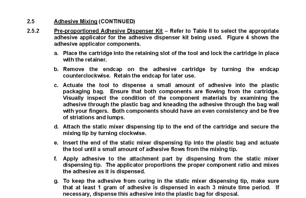
LSM Rev P
|
|
|
- Logan McGee
- 5 years ago
- Views:
Transcription
 Cessna Citation Model 560XL Landing Lights Excel (S/N 560-5001 thru 560-5372), XLS (S/N 560-5501 thru 560-6000), XLS+ (S/N 560-6001 and Subs) STC ST02893AT LSM-500-099 Rev P")
1 Installation Instructions Cessna Citation CJ Series Landing Lights Models 525, 525A, 525B (S/N thru , 525A-0001 thru 525A-0416, 525B-0001 thru 525B-0262, 525B-0264 thru 525B-0293) Cessna Citation Model 560XL Landing Lights Excel (S/N thru ), XLS (S/N thru ), XLS+ (S/N and Subs) STC ST02893AT LSM Rev P
2 REVISION DESCRIPTION Rev Date Description IR Initial release. 1. CB92 qty was 2. A Deleted frame STA from weight and balance data. 3. Added optional ballast mounting location / orientation for older aircraft. 4. Revised note 7 to allow the use of a lubricant when installing the gasket over the reflector. 1. Added -3 kit for Model 560XL. B Revised weight and balance to add -3 kit. 3. Revised electrical load analysis to add -3 kit. 4. LSM-SCD W was LSM-SCD W. 5. Added alternate ballast mounting locations on fwd / aft compartment bulkheads and outboard skin. C Added -5 and -7 kits. 1. Deleted -5 and -7 kits. D LSM & -6 were LSM for -3 kit. 3. Added LSM qty 2 for -3 kit. 4. LSM-SCD qty was 2 for -3 kit. 5. LSM-SCD W qty was 2 for -3 kit. 6. MS qty was 16 for -3 kit. 7. CB92 qty was Added Figure Revised electrical load analysis and weight and balance for 560XL installation. 1. Deleted LSM-SCD qty 2 for -3 kit. E LSM was LSM for -3 kit. 3. LSM-SCD was LSM-SCD for -3 kit. 4. Deleted LSM-SCD W for -3 kit. 5. Deleted LSM for -3 kit. 6. Deleted AN315-3R for -3 kit. 7. Deleted MS for -3 kit. 8. Deleted AN for -3 kit. 9. Deleted NAS43DD3-48FC for -3 kit. 10. Deleted CS CR for -3 kit. 11. MS qty was 24 for -3 kit. 12. CB92 qty was 6 for -3 kit. 13. Added LSM qty Added MS qty Added AN960-8 qty 4. F LSM / -8 was LSM for -1 kit. 2. LSM was LSM-SCD for -1 kit. 3. Deleted LSM-SCD W, LSM , AN315-3R, MS , AN960-10, NAS43DD3-48FC and CS CR from -1 kit. 4. LSM-SCD qty was Model 525 weight and balance was +.7 pounds. 6. Model 525 electrical load analysis was 27.3 amperes less than stock system.
3 G LSM was LSM for -1 kit. 2. Added MS to -1 kit. 3. Added LSM-SCD qty 2 for -3 kit. 4. LSM qty was 1 for -3 kit. 5. Deleted LSM for -3 kit. 6. Deleted LSM for -3 kit. 7. Added LSM-SCD for -3 kit. 8. Deleted MS from -3 kit. 9. Deleted AN960-8 from -3 kit. 10. CB92 qty was 4 for -3 kit. H kit was Model 525 S/N 0001 thru Added -5 kit for Model 525 S/N 0001 thru I Added AN315-3R qty 6 for -3 kit. 2. Added MS qty 6 for -3 kit. 3. Added AN qty 12 for -3 kit. 4. Added CS CR qty 6 for -3 kit. 5. Added LSM qty 2 for -3 kit. 6. Added Figure 1. J Deleted LSM , -8 & -15 for -1 kit. 2. Added LSM qty 2 for -1 kit. 3. Added LSM qty 2 for -1 kit. 4. Added LSM qty 2 for -1 kit. 5. LSM qty was 2 for -5 kit. 6. Added LSM qty 1 for -5 kit. 7. Revised Figures 2 and 4. K Added CS CR qty 6 as alternate for -3 kit. 2. Added NAS43DD3-48FC qty 6 to -3 kit. 3. AN qty was 12 for -3 kit. 4. Added Figure 2 for ballast mounting option. L Added photo Revised Figure 5 to show connectors pointing outboard. 3. Revised ballast mounting for -5 kit to outboard of opening. M Added -7, -9, -11 kits. 2. Revised electrical load analysis. N Added ClickBond Stud Installation Instructions. P Revised CB92 Adhesive Kit to Customer Furnished
4 LSM Rev P Page 1 of 38 BOOM BEAM Thank you for your purchase of the LoPresti Speed Merchants BOOM BEAM. We have written this Installation Manual to make your installation as easy and professional as possible. Before you start: READ ALL INSTRUCTIONS Call us at if you have any questions. Begin by checking the contents of your kit against the list below W Wing Fairing Light Installation Kit Models 525, 525A, 525B (S/N thru , 525A-0001 thru 525A-0416, 525B-0001 thru 525B-0262, 525B-0264 thru 525B-0293) Nomenclature Part Number Vendor Quantity Light Array Assy LSM Fwd Retainer LSM Aft Retainer LSM Ballast Assy, 60W LSM Ballast to Power Wire LSM-SCD Harness Screw MS Cable Tie Wraps MS Splice M Shrink Tube M23053/ inches Adhesive CB92 Click Bond (3) Customer Furnished
5 LSM Rev P Page 2 of W Wing Fairing Light Installation Kit Cessna Citation Model 560XL Landing Lights Excel (S/N thru ), XLS (S/N thru ), XLS+ (S/N and Subs) Nomenclature Part Number Vendor Quantity Light Array Assy LSM Ballast Assy, 60W LSM Ballast Mounting LSM Guide Ballast, 60W LSM-SCD Ballast to Power LSM-SCD Wire Harness Nut AN315-3R 6 Stud CS CR Click Bond 6 Stud CS CR Click Bond 6 (Alternate) Washer AN Nut MS Spacer NAS43DD3-48FC 6 Cable Tie Wraps MS Splice M Shrink Tube M23053/ inches Adhesive CB92 Click Bond (6) Customer Furnished
6 LSM Rev P Page 3 of W Wing Fairing Light Installation Kit Model 525 (S/N 0001 thru 0175) Nomenclature Part Number Vendor Quantity Light Array Assy, LH LSM Light Array Assy, RH LSM Ballast Assy, 60W LSM Ballast to Power Wire LSM-SCD Harness Cable Tie Wraps MS Splice M Shrink Tube M23053/ inches Adhesive CB92 Click Bond (3) Customer Furnsihed
7 LSM Rev P Page 4 of W Wing Fairing Light Installation Kit Models 525, 525A, 525B (S/N thru , 525A-0001 thru 525A-0416, 525B-0001 thru 525B-0262, 525B-0264 thru 525B-0293) Nomenclature Part Number Vendor Quantity Light Array Assy LSM Fwd Retainer LSM Aft Retainer LSM Ballast Assy, 85W LSM Ballast to Power Wire LSM-SCD Harness Screw MS Cable Tie Wraps MS Splice M Shrink Tube M23053/ inches Adhesive CB92 Click Bond (3) Customer Furnished
8 LSM Rev P Page 5 of W Wing Fairing Light Installation Kit Cessna Citation Model 560XL Landing Lights Excel (S/N thru ), XLS (S/N thru ), XLS+ (S/N and Subs) Nomenclature Part Number Vendor Quantity Light Array Assy LSM Ballast Assy, 85W LSM Ballast Mounting LSM Guide Ballast, 85W LSM-SCD Ballast to Power LSM-SCD Wire Harness Nut AN315-3R 6 Stud CS CR Click Bond 6 Stud CS CR Click Bond 6 (Alternate) Washer AN Nut MS Spacer NAS43DD3-48FC 6 Cable Tie Wraps MS Splice M Shrink Tube M23053/ inches Adhesive CB92 Click Bond (6) Customer Furnished
9 LSM Rev P Page 6 of W Wing Fairing Light Installation Kit Model 525 (S/N 0001 thru 0175) Nomenclature Part Number Vendor Quantity Light Array Assy, LH LSM Light Array Assy, RH LSM Ballast Assy, 85W LSM Ballast to Power Wire LSM-SCD Harness Cable Tie Wraps MS Splice M Shrink Tube M23053/ inches Adhesive CB92 Click Bond (3) Customer Furnished
10 LSM Rev P Page 7 of 38 Installation Instructions 1. All instructions are typical for LH and RH of aircraft. Instructions are applicable to all aircraft models listed except where noted. 2. Remove the existing landing light assemblies. Detach the electrical leads, determine polarity and identify as power and ground. Remove the hardware securing the lanyards. Retain all hardware for later use. See photos 1 and 2. Photo #1 Model 525 View Looking Aft on LH Side


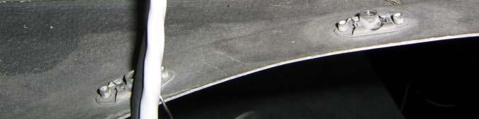
11 LSM Rev P Page 8 of 38 Ballast Mounting Location on Aircraft Skin Alternate Ballast Mounting Location on Fwd / Aft Compartment Bulkheads Photo #2 Model 525 View Looking Aft on LH Side 3. Remove the existing lamp and rubber gasket from the bracket. Retain the bracket attach hardware for later use. 4. For -1 / -5 and -7 / -11 Kit Installations: For the -1 and -7 kits, the LSM or LSM Ballast Assy will be mounted inboard of the LH & RH light access openings on the aircraft skin using ClickBond CB92 adhesive per ClickBond CBPS-206 instructions included. For the -5 and -11 kits, it is recommended that the Ballast Assy be mounted outboard of the light access openings. Position the ballasts to provide the optimum harness connector / ballast connector orientation prior to bonding. On older aircraft with the skin configuration shown in photos 3, 4 and 5, it is preferrable to mount the ballasts on the skin outboard of the landing lights. See photos 3, 4, 5 and 6. For -3 and -9 Kit Installation: The LSM or LSM Ballast Assy and LSM-SCD or LSM-SCD Ballast will be mounted inboard of the LH & RH light access openings on the aircraft skin using Click Bond CB92 adhesive per ClickBond CBPS-206 instructions included. An alternate mounting location is on the aft side of the bulkhead (FS 253.2) as shown in photos 8 and 9. It is suggested that the ballast assemblies be positioned to provide the optimum harness connector / ballast connector orientation prior to bonding. Attach the LSM Ballast Mounting Guide to the CS CR or CS CR studs using AN315-3 nuts prior to applying adhesive to the studs. See photo 6 and Figures 1 and 2.
12 LSM Rev P Page 9 of 38 Photo #3 Early Model 525 RH Side Alternate Ballast Mounting Location Photo #4 Model 525 (LSM Not Shown)


13 LSM Rev P Page 10 of 38 Photo #5 Model 525 (LSM Not Shown) Photo #6 Models 525, 525A, 525B (LSM Not Shown)


14 LSM Rev P Page 11 of 38 Photo #7 Model 560XL (LSM Not Shown) Photo #8 Model 560XL (LSM-SCD Shown)


15 LSM Rev P Page 12 of 38 Photo #9 Model 560XL (LSM Shown)
16 LSM Rev P Page 13 of 38
17 LSM Rev P Page 14 of When mounting the ballast assemblies, the adhesive will be applied directly to the studs and the entire assembly will be placed on the aircraft skin per ClickBond CBPS-206 instructions included. Prior to bonding, prepare the surface in accordance with the instructions included with the CB92 adhesive kit. Note: when installing ClickBond studs on metal, all surface finish must be removed prior to applying adhesive. Reapply finish as required after the adhesive has cured. Prepare the adhesive and apply to the bottom of the stud flanges. Position the studs to clear existing structure and fasteners and place firmly on the surface. The gap between the studs and the surface should be such that the adhesive outflows to form a fillet around the stud flange. Allow two hours at room temp for the adhesive to cure. Cured adhesive will be green in color. 6. For -1 / -7 Kit Installation: Remove the silicone cuffs from the stock landing lights and install on the LSM light array assemblies. Insert these units into the stock light housing. A small amount of moisture will help seat the cuff into the housing. Install the LSM forward retainer and the LSM aft retainer over the unit and secure using existing hardware. See Figure For -3 / -9 Kit Installation: Remove the cable ties securing the lamp/starter harness to the mounting plate and attach the LSM light array assemblies to the LH & RH light support brackets using existing hardware. See Figure For -5 / -11 Kit Installation: Remove the cuffs from the stock landing lights and install on the LSM & -10 light array assemblies. Install the cuff / light array assemblies into the stock holding fixtures with the lamp/starter connectors pointing outboard. Tighten the holding clamp hardware to secure the light array assemblies. See Figure 5.
18 LSM Rev P Page 15 of 38
19 LSM Rev P Page 16 of 38
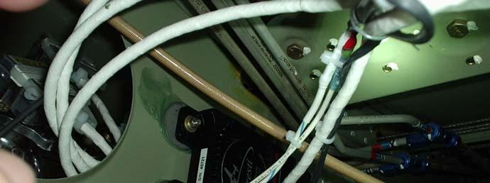
20 LSM Rev P Page 17 of For -1 / -7 and -5 / -11 Kit Installations: Attach the LSM-SCD Power Harnesses to the ballast connectors. Apply Dow Corning DC-4 (or other di-electric compound) to both connectors prior to attaching. Trim existing power and ground leads and harness leads to a length suitable for joining to the LSM-SCD Power Harness. Join two red leads to aircraft positive power and two black leads to aircraft ground wire using M splices and cover using M23053/ shrink tubing. See photos 10 and 11.


21 LSM Rev P Page 18 of 38 Photo #10 Photo # For -3 / -9 Kit Installation: Attach the LSM-SCD Power Harness to the ballast connectors. Apply Dow Corning DC-4 (or other di-electric compound) to all
22 LSM Rev P Page 19 of 38 connectors prior to attaching. Trim existing power and ground leads to a length suitable for joining to the LSM-SCD Power Harness leads. Join red soldered lead to aircraft positive power and black soldered lead to aircraft ground wire using M splices and cover using M23053/ shrink tubing. Typical for LH and RH of aircraft. 11. Attach the lamp/starter harnesses to the ballast connectors. 12. Secure all harnesses using MS cable tie wraps per AC B. 13. Do a power on test of the lighting system. Cycle power through the landing, taxi and recognition switch positions. 14. Reinstall the light assembly using existing hardware. Reseal the panel per the AMM instructions. 15. Fill out FAA Form 337.
23 LSM Rev P Page 20 of 38
24 LSM Rev P Page 21 of 38
25 LSM Rev P Page 22 of 38 Maintenance Requirements Instructions for Continued Airworthiness 1. Maintenance Manual information for the Boom Beam is contained in LoPresti Speed Merchants Installation Manual Number LSM (this document), and should be placed into the operators appropriate airplane Maintenance Manual. 2. Line Replaceable Unit (LRU) part numbers and other necessary part numbers contained in the installation data package should be placed into the aircraft operators appropriate airplane Illustrated Parts Catalog (IPC). 3. Wiring diagram information contained in this data package should be placed into the aircraft operator s appropriate airplane Wiring Diagram Manuals. 4. Scheduled Maintenance Program tasks to be added to the aircraft operators appropriate airplane maintenance program are as follows: 5. During an inspection interval of the lesser of 600 hours or one year, inspect the mechanical and electrical integrity of the BOOM BEAM equipment and components. All fasteners must be checked for tightness and all cable ties must be checked for the security of the wiring harnesses. Loose or broken fasteners or cable ties must be tightened or replaced. The wiring harnesses must be checked for frayed or damaged insulation, broken wires or connectors. Replace if damaged. The bulb/starters, ballasts and reflectors must be checked for soundness in mechanical and electrical conditions. Cracked or broken bulb/starter, ballast, or reflector must be replaced. Check for cracking in the reflector housing clamp flanges and for safety wire integrity (if existing). Damaged clamp or broken safety wire must be replaced.
26 LSM Rev P Page 23 of 38-1 Kit Installation: Change of +1.7 pounds. -3 Kit Installation: Change of +3.0 pounds. -5 Kit Installation: Change of +1.5 pounds. Weight and Balance Information Electrical Load Analysis For 60W Kit Installation: The new Boom Beam installation replaces the existing lights with a ballast and lamp assembly; a total of two assemblies. Each ballast assembly draws a maximum of 5.9 amperes at startup and then draws 2.4 amperes at steady state, after the lamps warm up. -1 and -5 Kit Installations: The total current required to operate the Boom Beam Lighting system is 22.5 amperes less than the existing system and therefore places no burden on the aircraft generating and distribution system. -3 Kit Installation: The total current required to operate the Boom Beam Lighting system is 28.5 amperes less than the existing system and therefore places no burden on the aircraft generating and distribution system. For 85W Kit Installation: The new Boom Beam installation replaces the existing lights with a ballast and lamp assembly; a total of two assemblies. Each ballast assembly draws a maximum of 8.4 amperes at startup and then draws 3.0 amperes at steady state, after the lamps warm up. -7 and -11 Kit Installations: The total current required to operate the Boom Beam Lighting system is 20.1 amperes less than the existing system and therefore places no burden on the aircraft generating and distribution system. -9 Kit Installation: The total current required to operate the Boom Beam Lighting system is 24.9 amperes less than the existing system and therefore places no burden on the aircraft generating and distribution system.

27 LSM Rev P Page 24 of 38
28 LSM Rev P Page 25 of 38
29 LSM Rev P Page 26 of 38
30 LSM Rev P Page 27 of 38
31 LSM Rev P Page 28 of 38
32 LSM Rev P Page 29 of 38
33 LSM Rev P Page 30 of 38
34 LSM Rev P Page 31 of 38
35 LSM Rev P Page 32 of 38
36 LSM Rev P Page 33 of 38
37 LSM Rev P Page 34 of 38

38 LSM Rev P Page 35 of 38

39 LSM Rev P Page 36 of 38

40 LSM Rev P Page 37 of 38

41 LSM Rev P Page 38 of 38
Cessna Caravan Wing Mounted Taxi/Landing Lights Installation Instructions Model 208, 208A, 208B LSM Rev E
 Cessna Caravan Wing Mounted Taxi/Landing Lights Installation Instructions Model 208, 208A, 208B LSM-500-040 Rev E 07-29-14 REVISION DESCRIPTION Rev Date Description IR 08-18-04 1. Initial release. A 08-26-08
King Air Wing Mounted Landing / Taxi Lights Installation Instructions Models A90, B90 LSM Rev IR
 King Air Wing Mounted Landing / Taxi Lights Installation Instructions Models A90, B90 LSM-500-096 Rev IR 09-17-2010 LoPresti Aviation 800-859-4757 / 772-562-4757 or fax 772-228-9750 http://www.loprestiaviation.com
INSTALLATION INSTRUCTIONS EXTERNAL AUXILIARY FUEL SYSTEM P/N
 INSTALLATION INSTRUCTIONS EXTERNAL AUXILIARY FUEL SYSTEM P/N 41228-000-002-007 Page 1 of 45 List of Revisions Rev. Date Pages Description Approved IR 09/12/05 All Initial Release N/C All Updated to Apical
Service Bulletin No.: DAC Rev. 0 Date Issued: 25 August 2014 Title: Installation of a Heated Pitot Static Probe Page: 1 of 34 PRINT IN COLOUR
 Title: Installation of a Heated Pitot Static Probe Page: 1 of 34 1. ATA Code: 3030 PRINT IN COLOUR 2. Effectivity: All DA20-C1 aircraft not equipped with recognition lights. 3. General: This Service Bulletin
PARAVION TECHNOLOGY, INC AIRWAY AVENUE FT. COLLINS, COLORADO 80524
 PARAVION TECHNOLOGY, INC. 2001 AIRWAY AVENUE FT. COLLINS, COLORADO 80524 DOCUMENT NO. INSTALLATION INSTRUCTIONS BELL 206A/B/L/L1/L3/L4 HELICOPTER MODELS Page i Rev. H, 02/06/06 REVISIONS REV. DATE DESCRIPTION
BRACKETT AERO FILTERS, INC.
 BRACKETT AERO FILTERS, INC. INSTRUCTIONS ASSEMBLY PART NO. BA-8110 FAA APPROVAL DATA: STC-SA71GL LIST NO. 1 FAA-PMA Supplement No. 1 REPLACES FILTER PART NUMBERS: 0750038-1, -4 0750127-12, -14 0750146-1
MODIFICATION KIT. Serial Numbers 300 (LC40-550FG) thru (LC42-550FG) thru (LC41-550FG) thru
 thru (LC42-550FG) thru (LC41-550FG) thru") Single Engine MODIFICATION KIT MK400-71-01 TITLE ENGINE OIL COOLER WINTERIZATION MODIFICATION EFFECTIVITY Model Serial Numbers 300 (LC40-550FG) 40004 thru 40079 350 (LC42-550FG) 42001 thru 421018 400 (LC41-550FG)
Single Engine MODIFICATION KIT MK400-71-01 TITLE ENGINE OIL COOLER WINTERIZATION MODIFICATION EFFECTIVITY Model Serial Numbers 300 (LC40-550FG) 40004 thru 40079 350 (LC42-550FG) 42001 thru 421018 400 (LC41-550FG)
57-20 AUXILIARY STRUCTURE
 AUXILIARY STRUCTURE 1. DESCRIPTION The leading edge of the wing is manufactured from composite materials. This airplane has a one-piece wing with individual wing tips. The wing tips are manufactured from
INSTRUCTIONS FOR CONTINUED AIRWORTHINESS AND EQUIPMENT MAINTENANCE MANUAL FOR Bell 212/ 412 CARGO NET/TROOP SEAT
 INSTRUCTIONS FOR CONTINUED AIRWORTHINESS FOR STC No. SR09485RC ON BELL 212/412 REPORT NUMBER HF-412-ICA-CARGO NET-01 HELIFAB 1318 SMEDE HWY. BROUSSARD, LA 70518 THIS MANUAL IS PREPARED TO PROVIDE INFORMATION,
CIRRUS AIRPLANE MAINTENANCE MANUAL
 AUXILIARY STRUCTURE 1. DESCRIPTION The leading edge of the wing is manufactured from composite materials. This airplane has a one-piece wing with individual wing tips. The wing tips are manufactured from
A bar next to the text in the right hand margin indicates that the text has been changed as a result of the most recent document revision.
 Cessna Aircraft Company Page 1 REVISIONS Rev Date By Approved By - 30 November 2009 Jay York A 18 March 2010 Jay York B 30 March 2010 Jay York ECR 067497 Section ALL Description Initial Release NOTE: A
IOF-240-B4B ENGINE CONVERSION. All IOF-240-B4B Engines
 SSI--002 REASON FOR ACTION PURPOSE COMPLIANCE MODELS AFFECTED FADEC Software Upgrade. To provide instructions for conversion of all IOF-240-B specification 4B engines to the IOF-240-B specification 5B.
RECORD OF REVISIONS. Prepared (name and date) (name and date) 11 November 2011
 (name and date) 11 November 2011") BLADE TIE -DOWN PROVISIONS AS 350 / AS 355 / EC 30 RECORD OF REVISIONS Rev. Pages at this Revision Description, Reason Changed Pages Prepared (name and date) Checked (name and date) App d/acc d (Civil
BLADE TIE -DOWN PROVISIONS AS 350 / AS 355 / EC 30 RECORD OF REVISIONS Rev. Pages at this Revision Description, Reason Changed Pages Prepared (name and date) Checked (name and date) App d/acc d (Civil
53-40 ATTACH FITTINGS
 ATTACH FITTINGS. DESCRIPTION Attach fittings are provided for attachment of the seats (Refer to -0), baggage straps (Refer to -0), rear seat harnesses (Refer to -0), cargo net straps (Refer to -0), cabin
Waco Regional Airport P.O. Box 5500 Waco, Texas Beechcraft King Air 200 & 300 Series Airplanes INSTRUCTIONS FOR CONTINUED AIRWORTHINESS
 Waco Regional Airport P.O. Box 5500 Waco, Texas 76708 Beechcraft King Air 200 & 300 Series Airplanes INSTRUCTIONS FOR CONTINUED AIRWORTHINESS ICA Manual No. 26012-30 Revision 1 DEC. 2015 RECORD OF REVISIONS
CESSNA CITATION MODEL 500/501 INCREASED RAMP AND TAKEOFF WEIGHT INSTALLATION 1 SEPTEMBER 1994
 MAINTENANCE MANUAL SUPPLEMENT NFC Document No. CESSNA MODEL 500/501 INCREASED RAMP AND TAKEOFF WEIGHT INSTALLATION 1 SEPTEMBER 1994 This supplement must be attached to the Cessna Citation Model 500/501
Aileron Pulley Shield ICA Supplement
 CESSNA AIRCRAFT COMPANY AIRCRAFT DIVISION WICHITA, KANSAS 67277 Aileron Pulley Shield ICA Supplement MODEL NO: 510 SUPPLEMENT NO: ICA-510-27-00002 SUPPLEMENT DATE: 05/18/2010 PREPARED BY: CHECKED BY: APPROVED
PARAVION TECHNOLOGY, INC AIRWAY AVENUE FT. COLLINS, COLORADO 80524
 [Rev. 5, 11/07/07] PARAVION TECHNOLOGY, INC. 2001 AIRWAY AVENUE FT. COLLINS, COLORADO 80524 INSTRUCTIONS FOR CONTINUED AIRWORTHINESS 407H-120M BLEED-AIR CABIN HEATER INSTALLATION BELL MODEL 407 HELICOPTERS
FOR REVIEW SERVICE BULLETIN SB-AG-65. Installation of Click Bond Electrical Grounding Spacer Stud on the Header Tank. Revision IR 11/20/2017
 SERVICE BULLETIN SB-AG-65 Revision IR 11/20/2017 Installation of Click Bond Electrical Grounding Spacer Stud on the Header Tank James Alman Vice President of Engineering i AIRCRAFT AFFECTED: MODEL SERIAL
CIRRUS AIRPLANE MAINTENANCE MANUAL
 POWER CONTROL. DESCRIPTION This section describes those components which furnish a means of controlling engine power. Engine controls for the airplane include the following: control quadrant, throttle
Page: REV 1: In Step 4 "a minimum of 1/16 [1.6 mm] gap" was "an approximately 1/16 [1.6 mm] gap."
![Page: REV 1: In Step 4 a minimum of 1/16 [1.6 mm] gap was an approximately 1/16 [1.6 mm] gap.](/thumbs/72/66557156.jpg "Page: REV 1: In Step 4 a minimum of 1/16 [1.6 mm] gap was an approximately 1/16 [1.6 mm] gap.") 14401 Keil Road NE, Aurora, Oregon, USA 97002 PHONE 503-678-6545 FAX 503-678-6560 www.vansaircraft.com info@vansaircraft.com Service Letters and Bulletins: www.vansaircraft.com/public/service.htm REVISION
14401 Keil Road NE, Aurora, Oregon, USA 97002 PHONE 503-678-6545 FAX 503-678-6560 www.vansaircraft.com info@vansaircraft.com Service Letters and Bulletins: www.vansaircraft.com/public/service.htm REVISION
CIRRUS AIRPLANE MAINTENANCE MANUAL
 MODEL SR0 EXTERIOR LIGHTING. DESCRIPTION This section covers that portion of the system which provides illumination outside of the aircraft. This includes the landing light, anti-collision strobe light,
Service Bulletin No.: D42L Rev 2 Date Issued: 05 October 2012 Title: ADF System Improvements Page: 1 of 16
 Title: ADF System Improvements Page: 1 of 16 1. ATA Code: 3450 2. Effectivity: All DA42 aircraft with Transport Canada Civil Aviation (TCCA) STC SA09-54 or Federal Aviation Administration (FAA) STC SA02725NY
EFFECTIVITY Serial Numbers thru , 698
 Conquest TITLE AILERON HINGE BRACKET REPLACEMENT EFFECTIVITY Model Serial Numbers 441 441-0001 thru 441-0349, 698 DESCRIPTION To install stainless-steel aileron hinge brackets as a replacement for aluminum
Airworthiness Directive Schedule
 Airworthiness Directive Schedule Aeroplanes Cessna 120 26 November 2015 Notes 1. This AD schedule is applicable to Cessna 120 aircraft manufactured under Federal Aviation Administration (FAA) Type Certificate
SERVICE BULLETIN. The equivalent of this service bulletin has been incorporated on production airplanes and On.
 TITLE ICE AND RAIN PROTECTION - WING ANTI-ICE SYSTEM IMPROVEMENT EFFECTIVITY MODEL SERIAL NUMBERS 525B -0002 thru -0012 The equivalent of this service bulletin has been incorporated on production airplanes
ILLUSTRATED PARTS CATALOG STC SR01616SE
 ILLUSTRATED PARTS CATALOG STC SR066SE ENGINE INLET BARRIER FILTER SYSTEM Sikorsky S-76A+/A++/C/C+ This document provides information to assist with the identification of parts and assemblies for the 076T-
Revision Transmittal Sheet
 2 APPROVED WHITE IN LEARJET 31 RT 31-32-24 Revision Transmittal Sheet This page transmits Revision 1 to No. 31-32-24, Main Landing Gear Torque Link Replacement. Rework: No rework is required for aircraft
SERVICE LETTER. Multi-engine TITLE NACELLES/PYLONS - NACELLE FITTING INSPECTION EFFECTIVITY
 TITLE NACELLES/PYLONS - NACELLE FITTING INSPECTION EFFECTIVITY REASON MODEL 402C 414A SERIAL NUMBERS 402C0001 thru 402C1020 that have SK402-47 - Lower Front Wing Spar Cap Inspection/Modification (Original
REVISION LIST CHAPTER 21: FLAP SYSTEM COMPLETION
 REVISION LIST CHAPTER 21: The following list of revisions will allow you to update the Legacy construction manual chapter listed above. Under the Action column, R&R directs you to remove and replace the
SERVICE INSTRUCTION SI Revision 1
 SERVICE INSTRUCTION SI-25-02 Revision 1 TITLE: Aft Seats Inertia Reel Harness Installation (Mod 1229) SUBJECT / REASON / DESCRIPTION: The FBA-2C1 and FBA-2C2 aircraft are equipped with three individual
AIRWOLF AEROSPACE LLC
 AIRWOLF AEROSPACE LLC 15369 Madison Rd. Middlefield, OH 44062-8404 U.S.A. (440) 632-1687 / (440) 632-1685 Fax www.airwolfaeospace.com / info@airwolfaerospace.com Installation Instructions For The Installation
Service Bulletin No.: DA C , Rev.0 Date Issued: October 8, 1998 Title: Type II Fuel System/Pump Retrofit Page: 1 of 13
 Title: Type II Fuel System/Pump Retrofit Page: 1 of 13 1. ATA Code: 2810 PLANNING INFORMATION: 2. Effectivity: DA20-C1 aircraft with Type I fuel systems S/N C0002 - C0013. DA20-C1 aircraft with Facet fuel
FUEL SYSTEM WIRING, INSTALLATION OF TRANSIENT SUPPRESSION UNITS (TSU S)
") Page: 1 of 24 TITLE: FUEL SYSTEM WIRING, INSTALLATION OF TRANSIENT SUPPRESSION UNITS (TSU S) 1.0 SUMMARY 1.1. Reason Provide an Alternate Means of Compliance (AMOC) to Airworthiness Directive (AD) 99-03-
Page: 1 of 24 TITLE: FUEL SYSTEM WIRING, INSTALLATION OF TRANSIENT SUPPRESSION UNITS (TSU S) 1.0 SUMMARY 1.1. Reason Provide an Alternate Means of Compliance (AMOC) to Airworthiness Directive (AD) 99-03-
Service Bulletin. ATA 27-00: Flight Controls Rudder-Aileron Interconnect Modification
 Service Bulletin Issued: 09 May 2007 Models SR20 and SR22 ATA 27-00: Flight Controls Rudder-Aileron Interconnect Modification COMPLIANCE Mandatory: Accomplish this Service Bulletin within 25 Flight Hours
FLAP, AILERON, FLAP/FUSELAGE AND STABILATOR GAP SEAL INSTALLATION AND MAINTENANCE MANUAL
 FLAP, AILERON, FLAP/FUSELAGE AND STABILATOR GAP SEAL INSTALLATION AND MAINTENANCE MANUAL Aircraft Eligibility: Piper PA-28-151, PA-28-161, PA-28-181, PA-28-201T, PA-28-236, PA- 28R-201, PA-28R-201T, PA-28RT-201,
PARAVION TECHNOLOGY, INC AIRWAY AVENUE FORT COLLINS, COLORADO REPORT NO. PR-206H-900M CABIN HEATER SYSTEM INSTALLATION INSTRUCTIONS
 PARAVION TECHNOLOGY, INC. 2001 AIRWAY AVENUE FORT COLLINS, COLORADO 80524 REPORT NO. CABIN HEATER SYSTEM INSTALLATION INSTRUCTIONS BELL 206A/B HELICOPTERS Page i PR- Rev. P, 04/06/09 REVISIONS REV. DATE
SERVICE KIT thru , 631, 634, 675 R thru R F thru F FR thru FR
 TITLE SEAT BELT AND SHOULDER HARNESS KIT INSTALLATION EFFECTIVITY MODEL SERIES SERIAL NUMBERS 182 33000 thru 18268368 182 613, 631, 634, 675 R182 R18200001 thru R18201973 F182 F18200001 thru F18200169
Airworthiness Directive Schedule
 Airworthiness Directive Schedule Aeroplanes 31 March 2011 Notes 1. This AD schedule is applicable to Allied Ag Cat Productions G-164A, G164B and G- 164B-20T aircraft (formerly Schweizer Aircraft Corp.)
33-40 EXTERIOR LIGHTING
 EXTERIOR LIGHTING. DESCRIPTION This section covers that portion of the system which provides illumination outside of the aircraft. This includes the landing light, anti-collision strobe light, and recognition
SERVICE BULLETIN. To prevent the wing fuel boost pump wiring from chafing on the wing structure and/or fuel tube assemblies.
 TITLE FUEL - WING FUEL BOOST PUMP WIRE ROUTING IMPROVEMENT EFFECTIVITY MODEL UNIT NUMBERS 500/501-0001 thru -0689 REASON To prevent the wing fuel boost pump wiring from chafing on the wing structure and/or
MANPOWER REQUIREMENTS
 CIRRUS SF5X Service Bulletin Number: Issued: Revised: 09 Aug 208 SNS SUBJECT: 25-0 CABIN - Armrest Installation. COMPLIANCE Optional: Accomplishment of this Service Bulletin is at the owner s option. This
REPORT NO: R-786 CARGO DOOR C-CHECK INSPECTION PROCEDURES
 MP 1 of 7 REPORT NO: CARGO DOOR C-CHECK INSPECTION PROCEDURES Date: July 16, 2004 Rev IR March 15, 2012 Rev. B June 6,2013 Rev. C April 24, 2015 Rev. D MP 2 of 7 REVISION DATE PAGES AFFECTED DESCRIPTION
1) Page: REV 5: Changed depiction to show added hardware and T-01220
 Page: REV 5: Changed depiction to show added hardware and T-01220") REVISION DESCRIPTION: 1) Page: 37-01 REV 5: Changed depiction to show added hardware and T-01220 Page: 37-02 REV 4: Added Figure 3 depicting Separating the T-01220 Doublers. Figure 4 was Figure 3. Added
REVISION DESCRIPTION: 1) Page: 37-01 REV 5: Changed depiction to show added hardware and T-01220 Page: 37-02 REV 4: Added Figure 3 depicting Separating the T-01220 Doublers. Figure 4 was Figure 3. Added
Rotary Speed Brake Actuation System ICA Supplement
 CESSNA AIRCRAFT COMPANY AIRCRAFT DIVISION WICHITA, KANSAS 67277 Rotary Speed Brake Actuation System ICA Supplement MODEL NO: 510 SUPPLEMENT NO: ICA-510-27-00001 SUPPLEMENT DATE: 04/28/2009 PREPARED BY:
Hiniker Company th St. P.O. Box 3407 Mankato, MN 56002
 VEHICLE INSTALLATION INSTRUCTIONS FOR: FORD 4x4: 008-06 SUPER DUTY F50-350 - 450-550 Page of 5 Hiniker Company 58766 40th St. P.O. Box 3407 Mankato, MN 5600 INSTRUCTION SHEET NO: 50370 Rev. B September
12/03 EXPLODED VIEW 1) L angles on first rear rib: moved from inboard to outboard side of rib (12/03)
 L angles on first rear rib: moved from inboard to outboard side of rib (12/03)") ZODIAC CH 601 XL Drawing list December 04, 2003 3 rd revision of 2 nd edition 12/03 Summary of revisions from 07/03 to 11/03 AIRFRAME 6-X-0 DRAWING LIST Dec 4, 2003 6-X-1 6-T-0 6-T-1 6-T-2 6-T-3 6-T-4
ZODIAC CH 601 XL Drawing list December 04, 2003 3 rd revision of 2 nd edition 12/03 Summary of revisions from 07/03 to 11/03 AIRFRAME 6-X-0 DRAWING LIST Dec 4, 2003 6-X-1 6-T-0 6-T-1 6-T-2 6-T-3 6-T-4
Revision Transmittal Sheet
 b 2 APPROVED WHITE IN LEARJET 23/24/25, 28/29, 35/36 RT 0980 Revision Transmittal Sheet This page transmits Revision 1 to, Replacement of Air Conditioning Evaporator Assembly. Rework: No rework is required
ILLUSTRATED PARTS CATALOG SUPPLEMENT. Eyebrow Window Replacement SUPPLEMENTAL TYPE CERTIFICATE: ST01630SE. AIRPLANE MAKE: Boeing
 ILLUSTRATED PARTS CATALOG SUPPLEMENT SUPPLEMENTAL TYPE CERTIFICATE: ST01630SE AIRPLANE MAKE: Boeing AIRPLANE MODEL: 737-100, -200, -200C, -300, -400, -500 TO BE ADDED TO IPC CHAPTER 56-11-31-XX Page 1
performance S T O L Installation Instructions Manual No. PSTOL-013 Double Slotted Flaps for Piper PA-18 Series Aircraft
 performance S T O L Installation Instructions Manual No. PSTOL-013 Double Slotted Flaps for Piper PA-18 Series Aircraft 1 This Page Intentionally Left Blank 2 Record of Revisions Rev Level Date Page By
RUN/BRAKE/TURN AUXILIARY LIGHTS J
 RUN/BRAKE/TURN AUXILIARY LIGHTS J06236 2018-05-31 GENERAL Kit Numbers 67800589A, 69202276 Models For model fitment information, see the P&A retail catalog or the Parts and Accessories section of www.harleydavidson.com
SERVICE BULLETIN REVISION TRANSMITTAL
 REVISION TRANSMITTAL REASON This sheet transmits Revision 1 to, which: A. Adds instructions and parts to change the Pulselite controller for airplanes with the Pulselite feature. NOTE: This revision replaces
FITTING KIT No s : BULL BAR WINCH ( P/No ) BULL BAR NON WINCH ( P/No )
 BULL BAR NON WINCH ( P/No )") ARB WINCH / NON WINCH BULL BAR TO SUIT LANDROVER DISCOVERY 2003 ONWARD. FITTING KIT No s :- 617 1793 BULL BAR WINCH ( P/No 343 2120 ) 617 1794 BULL BAR NON WINCH ( P/No 323 2120 ) WARNING FOR VEHICLES
ARB WINCH / NON WINCH BULL BAR TO SUIT LANDROVER DISCOVERY 2003 ONWARD. FITTING KIT No s :- 617 1793 BULL BAR WINCH ( P/No 343 2120 ) 617 1794 BULL BAR NON WINCH ( P/No 323 2120 ) WARNING FOR VEHICLES
2016 AeroLEDs LLC Rev: A Page 1
 Document 0000-0003 Installation Guide: AeroLEDs LLC Aerosun 8475 W Elisa Street P/N 01-2120 Boise, ID 83709 LED Landing light with Phone: (208) 850-3294 built-in pulse recognition mode www.aeroleds.com
56 - EFFECTIVE PAGES. Beechcraft Corporation PAGE 1 SUPER KING AIR B200GT SERIES ILLUSTRATED PARTS CATALOG DATE CH-SECT-UNIT-FIG
 CH-SECT-UNIT-FIG PAGE NO. DATE CH-SECT-UNIT-FIG PAGE NO. DATE 56 - CONTENTS 1 56-10-00-04 0 56-10-00-04 1 56-10-00-05 0 56-10-00-05 1 56-10-00-05 2 56-20-00-07 0 56-20-00-07 0A 56-20-00-07 1 56-20-00-07
Side Rocker Installation Instructions
 Side Rocker Installation Instructions Guidelines + Trial fit all parts prior to painting + Do not use the side rockers as an attachment point for tie downs + Every 3-6 months, make sure all fasteners are
ARB WINCH/NON WINCH BUMPER TO SUIT MITSUBISHI PAJERO NM FLARED. EXCLUDING EXCEED MODEL WARNING
 ARB WINCH/NON WINCH BUMPER TO SUIT MITSUBISHI PAJERO NM FLARED. EXCLUDING EXCEED MODEL PRODUCT No. 3934020 Sahara Bar 3034020 Sahara Bumper FITTING KIT No. 6171383, 6171762, 6171363 WARNING FOR VEHICLES
Single Engine. Service Bulletin TITLE ELEVATOR TRIM TAB ACTUATOR ASSEMBLY INSPECTION EFFECTIVITY. Group A airplanes: Serial Numbers
 Single Engine Service Bulletin March 12, 2007 TITLE ELEVATOR TRIM TAB ACTUATOR ASSEMBLY INSPECTION EFFECTIVITY Group A airplanes: Model Serial Numbers 172R 17281353 thru 17281364, 17281369 thru 17281372
Oil Filter Kit AFC-K005
 22. 21. 20. 12. 03. 04. 06. 07. 24. 11. 05. 09. 08. 02. 01. 17. 19. 18. 23. 25. 13. 14. 15. 10. 11. 16. Oil Filter Kit AFC-K005 27. 26. Applicability: Aviat Husky Model A-1 with Lycoming First Release:
SERVICE BULLETIN REVISION
 Revision 1 REVISION TRANSMITTAL SHEET This sheet transmits Revision 1 to. A. Adds Sheet 4 to Figure 1. B. Adds instructions to make the cutouts in the stiffener on the upper engine cowl larger. NOTE: This
2016 AeroLEDs LLC Rev: A Page 1
 Document 0104-0003 Installation Guide: AeroLEDs LLC Microsun 8475 W. Elisa Street P/N 01-1170 Boise, Idaho 83709 LED light with Phone: (208) 850-3294 built-in pulse recognition mode www.aeroleds.com sales@aeroleds.com
*407AC-110-3, REV. D ITEM # P/N DESCRIPTION QTY TYP 0 *407AC-110-3, REV. D AIR CONDITIONER INSTALLATION 1 KIT
 Bill of Materials *407AC-110-3, REV. D ITEM # P/N DESCRIPTION QTY TYP 0 *407AC-110-3, REV. D AIR CONDITIONER INSTALLATION 1 KIT 2 407AC-210-1 CONDENSER INSTALLATION 1 KIT 3 407AC-310-3 COMPRESSOR INSTALLATION
Service Bulletin No.: DAC Rev 3 Date Issued: October 27, 1999 Title: 2-Speed Electric Prime Fuel Pump Page: 1 of 8
 Title: 2-Speed Electric Prime Fuel Pump Page: 1 of 8 1. ATA Code: 2820 2. Effectivity: DA20-C1 Aircraft from S/N C0001 up to and including S/N C0089 3. General: This service bulletin addresses the installation
2012 AeroLEDs LLC Rev: A Page 1
 Document 0013-0004 Installation Guide: AeroLEDs LLC Sunbeam 967 East Park Center Boulevard P/N 90-1000 Suite # 381 LED Landing light with Boise, ID 83706-6700 built-in pulse recognition mode Phone: (208)
FOG-LAMPS INSTALL KIT
 FOG-LAMPS INSTALL KIT DODGE RAM (BR, BE) Installation Instructions Read entire instructions thoroughly before starting. For proper removal and installation, follow procedures in the service manual. NOTES:
Revision Control Page REPORT PFS Kit PFS REVISION DATE REMOVE PAGES
 Revision Control Page REPORT PFS-0020-00 Kit PFS-13203 REVISION DATE REMOVE PAGES INSERT PAGES IR 06/27/00 N/A N/A A 09/21/00 1,2,4,14 1,2,4,14 B 02/12/01 1,2,4,8,9,13 1,2,4,8,9,13 C 09/14/01 1,2,3,4,5,6,7,8
Hiniker Company th St. P.O. BOX 3407 Mankato, MN VEHICLE INSTALLATION INSTRUCTIONS FORD 4x4: SUPER DUTY F
 Page of VEHICLE INSTALLATION INSTRUCTIONS FORD x: 00-007 SUPER DUTY F0 30 0 0 INSTRUCTION SHEET NO: 037 Rev. A IMPORTANT: Read The Snowplow Operators Manual Before Assembling This Kit. MFR. Snowplow Prep
WARNING TAKE NOTE OF THE FOLLOWING: THIS PRODUCT MUST BE INSTALLED EXACTLY AS PER THESE INSTRUCTIONS USING ONLY THE HARDWARE SUPPLIED.
 ARB WINCH/NONWINCH BUMPER TO SUIT TOYOTA HJ100 IFS PRODUCT No. 3913140 5100050 Top Tube Kit 5100160 Buffer Kit With hole (required when fitting Top Tube) 5100170 Buffer Kit With no hole Fitting Kit No.
Power Flow System Extractor Exhaust System Installation Instructions Cessna 172, 175 TABLE OF CONTENTS
 Heading Power Flow System Extractor Exhaust System Installation Instructions TABLE OF CONTENTS Pages Introduction 3 Kit Contents Classic Tailpipes 4 Kit Contents Short Stack Tailpipes 5 Preparation 6 Removal
SAMPLE BLUE STAR CONVERSION INSTALLATION OF CONTINENTAL IO-470-C OR IO-470-N BEECH MODELS THROUGH F-33 LWS STC # SA5527SW REVISION 5
 BLUE STAR CONVERSION INSTALLATION OF CONTINENTAL IO-470-C OR IO-470-N BEECH MODELS 35-33 THROUGH F-33 LWS 470-33 STC # SA5527SW REVISION 5 FEBRUARY 5, 1996 BLUE STAR CONVERSION TABLE OF CONTENTS PAGE DESCRIPTION
SERVICE BULLETIN THIS BULLETIN IS FAA APPROVED FOR ENGINEERING DESIGN
 MOONEY INTERNATIONAL CORPORATION SERVICE BULLETIN 165 Al Mooney Road North Kerrville, Texas 78028 THIS BULLETIN IS FAA APPROVED FOR ENGINEERING DESIGN SERVICE BULLETIN M20-318 Date: June 2, 2014 SUBJECT:
SERVICE BULLETIN. To prevent the wing fuel boost pump wiring from chafing on the wing structure and/or fuel tube assemblies.
 TITLE FUEL - WING FUEL BOOST PUMP WIRE ROUTING IMPROVEMENT EFFECTIVITY MODEL SERIAL NUMBERS 560-0001 thru -0538 REASON To prevent the wing fuel boost pump wiring from chafing on the wing structure and/or
SUBJECT: FUEL SYSTEM FLOW SWITCHES, P/N , , -003, -101 AND -103, REPLACEMENT OF
 ALERT SERVICE BULLETIN 206L-88-52 10 June 1988 Revision A, 26 March 2013 MODEL AFFECTED: 206L and 206L-1 SUBJECT: FUEL SYSTEM FLOW SWITCHES, P/N 206-063- 635-001, 206-064-601-001, -003, -101 AND -103,
PC-6 SERVICE BULLETIN NO: 180 REF NO: 180 MODIFICATION NO: N/A ATA CHAPTER: 27. All PC-6 aircraft. None.
 3,/$786$,5&5$)7/7'&+67$166:,7=(5/$1' SERVICE BULLETIN NO: 180 REF NO: 180 MODIFICATION NO: N/A ATA CHAPTER: 27 )/,*+7&21752/6+25,=217$/67$%,/,=(5,167$//$7,212)$75,0:$51,1*6
SERVICE BULLETIN SB
 TITLE LIGHTS - LED POSITION, TAIL POSITION, AND ANTI-COLLISION (PTA) LIGHT INSTALLATION EFFECTIVITY MODEL SERIAL NUMBERS 560 (Citation Encore) -0539 thru -0707 560 (Citation Encore+) -0751 thru -0802 NOTE:
LANCAIR LEGACY PRE-TEST FLIGHT INSPECTION (8-04)
") LANCAIR LEGACY PRE-TEST FLIGHT INSPECTION (8-04) OWNER PHONE # ADDRESS N SERIAL # AIRCRAFT TYPE DATE / / TACH TIME hrs. TOTAL TIME hrs. EMPTY WEIGHT CG. PAINT & INTERIOR? YES NO ENGINE TYPE PROPELLER ALL
LANCAIR LEGACY PRE-TEST FLIGHT INSPECTION (8-04) OWNER PHONE # ADDRESS N SERIAL # AIRCRAFT TYPE DATE / / TACH TIME hrs. TOTAL TIME hrs. EMPTY WEIGHT CG. PAINT & INTERIOR? YES NO ENGINE TYPE PROPELLER ALL
Mahindra Pikup (2009 Production Onwards)
") Mahindra Pikup (009 Production Onwards) Steel Bull Bar INSTALLATION INSTRUCTIONS Accessory Part No. BBAR07 Installation Time: 60min Approx Bull Bar Weight: 60KG! Important: Please read each step of these
Mahindra Pikup (009 Production Onwards) Steel Bull Bar INSTALLATION INSTRUCTIONS Accessory Part No. BBAR07 Installation Time: 60min Approx Bull Bar Weight: 60KG! Important: Please read each step of these
*MANDATORY SERVICE BULLETIN*
 NUMBER: SB-022 REVISION: B DATE: 10/30/2009 SUBJECT: PITOT STATIC SYSTEM; MANDATORY MODIFICATION KODIAK MANDATORY SERVICE BULLETIN *MANDATORY SERVICE BULLETIN* SUMMARY *MANDATORY SERVICE BULLETIN* RECURRENT
CESSNA 180 & 182 Series Parts Catalog (1953 thru 1962), CD-ROM
, CD-ROM") CESSNA 180 & 182 Series Parts Catalog (1953 thru 1962), CD-ROM REVISION INFORMATION - 5/11/2001 This product is sold "as is". The end-user is responsible for determining the accuracy of the information
CESSNA 180 & 182 Series Parts Catalog (1953 thru 1962), CD-ROM REVISION INFORMATION - 5/11/2001 This product is sold "as is". The end-user is responsible for determining the accuracy of the information
Accident Prevention Program
 Accident Prevention Program Maintenance Aspects of Owning Your Own Airplane Introduction As an owner-pilot, FAR Part 43 allows you to perform certain types of inspections and maintenance on your airplane.
Flaps System. 1. General
 CIRRUS AIRPLANE MAINTENANCE MANUAL Flaps System CHAPTER 27-50: FLAPS SYSTEM GENERAL 27-50: FLAPS SYSTEM 1. General This section describes that portion of the flight control system which controls the position
Service Bulletin No: Ref No: 165 Modification No: EC ATA Chapter: 21
 PILATUS AIRCRAFT LTD. STANS, SWITZERLAND Service Bulletin No: 21-012 Ref No: 165 Modification No: EC-14-0359 ATA Chapter: 21 AIR CONDITIONING - COOLING INSTALL A COVER ASSEMBLY TO THE COMPRESSOR TO PROTECT
Waco Regional Airport P.O. Box 5500 Waco, Texas Beechcraft King Air 200 & 300 Series Airplanes INSTRUCTIONS FOR CONTINUED AIRWORTHINESS
 Waco Regional Airport P.O. Box 5500 Waco, Texas 76708 Beechcraft King Air 200 & 300 Series Airplanes INSTRUCTIONS FOR CONTINUED AIRWORTHINESS ICA Manual No. 26012-30 Revision 3 February 2019 RECORD OF
Instructions for Continued Airworthiness for the Installation of the HD Extended Maule Main Gear Assembly ABI-4022X
 ABI-4022X-ICA-RevC Instructions for Continued Airworthiness for the Installation of the HD Extended Maule Main Gear Assembly ABI-4022X Document Number: ABI-4022X-ICA Revision C 02/17/12 02/17/12 ABI-4022X-ICA
CIRRUS AIRPLANE MAINTENANCE MANUAL
 ELEVATOR AND PITCH TRIM SYSTEM 1. DESCRIPTION This section describes that portion of the flight control system which controls the position and movement of the elevator. Included are; elevator system torque
SERVICE LETTER NUMBER 173
 By: RCG Approved: JRS Date: 8/16/2017 Rev: A SERVICE LETTER NUMBER 173 10000 BULKHEAD 7 STIFFENER ADDITION Aircraft Makes/Model(s): AT-802 AT-802A Float Model(s): 10000A Note(s): Mandatory Compliance Service
SERVICE BULLETIN NO. OSB
 Page 1 of 12 SERVICE BULLETIN NO. OSB817-067 I. TECHNICAL DETAILS 1.1 Category: Optional 1.2 Airplanes affected: all S/N 1.3 Time of Compliance: On holders discretion 1.4 Subject: ATA-Code: 33-40 Exterior
RECOMMENDED SEQUENCE OF APPLICATION
 TOYOTA CAMRY 2012- PART NUMBER: 250-8402 REARSIGHT KIT CONTENTS ITEM QTY DESCRIPTION 1 1 INTERFACE ADAPTER HARNESS 2 1 REAR CAMERA ASSEMBLY 3 1 CAMERA EXTENSION HARNESS 4 1 SACK PARTS COLOR APPLICABILITY/TRIM
SCION tc FOG LIGHT. Part Number: STC-312 / STC-812
 SCION tc 2011-2013 FOG LIGHT Part Number: STC-312 / STC-812 Kit Contents Item # Quantity Reqd. Description 1 2 Fog Lamps 2 2 Fog Light bezels 3 1 Switch Assembly 4 1 Fog Light Operation guide 5 1 Harness
FJ44 SERVICE BULLETIN
 Engine Indicating FADEC Engine Harness Assembly Re-route 1. Planning Information A. Effectivity: This service bulletin applies to the following Williams International turbofan engines: ENGINE MODEL NUMBER
BRACKETT AERO FILTERS, INC.
 BRACKETT AERO FILTERS, INC. INSTRUCTIONS ASSEMBLY PART NO. BA-9110 (BA-S108K) APPROVED ON AIRCRAFT MODELS: Stinson 108, 108-1, 108-2, 108-3 FAA APPROVAL DATA: STC-SA71GL List No. 1 FAA-PMA Supplement No.
WARNING. When installed in accordance with these instructions, the front protection bar does not affect operation of the SRS airbag.
 Part Number: 36030 Product Description: BULL BAR WINCH TYPE Suited to vehicle/s: CHEVROLET C/K 500-3500 988-998 YEAR MODEL RANGE AND Warn 9,500-5,000lb WINCHES WARNING REGARDING VEHICLES EQUIPPED WITH
AIRGLAS. MODEL L20500 Ski Kit for Sikorsky UH60A, J, L, M MH60G, K, L Helicopters CODE INDENT. NO AIRGLAS MANUAL NO. L20500
 THIS MANUAL INCLUDES INFORMATION PROPRIETARY TO AND SHALL NOT BE USED TO MANUFACTURE OR REPRODUCE WITHOUT PERMISSION OF AIRGLAS MODEL L20500 Ski Kit for Sikorsky UH60A, J, L, M MH60G, K, L Helicopters
Nomad WINGS FUEL TANK BAYS FRONT AND REAR SPARS CORROSION INSPECTION
 WINGS FUEL TANK BAYS FRONT AND REAR SPARS CORROSION INSPECTION 1. PLANNING INFORMATION A. Effectivity (1) Aircraft affected: (a) N22 Series line sequence numbers 1 to 9, 11 to 29, 31, 33, 35, 37, 39 to
Install manual/service Letter
 Install manual/service Letter Doc No: NC-08-006 Rev D 1625 Lost Nation Rd., Willoughby, OH 44094 PH: 440-951-4744 FAX:440-951-4725 Issue Date: 16 May 2008 EFFECTIVITY Cessna Aircraft Types: 182T, T182T
SERVICE BULLETIN SB00029 Rev B Page 1 of 19
 SERVICE BULLETIN SB00029 Rev B Page 1 of 19 This Service Bulletin meets requirements of ASTM F2295-06. It is a Safety Directive for the purpose of compliance with 14 CFR 91.327(b)(4). EFFECTIVE DATE: This
CANVAS DOOR KIT P/N , APPLICATION BEFORE YOU BEGIN KIT CONTENTS. Verify accessory fitment at Polaris.com.
 CANVAS DOOR KIT P/N 2882902, 2882903 APPLICATION Verify accessory fitment at Polaris.com. BEFORE YOU BEGIN Read these instructions and check to be sure all parts and tools are accounted for. Please retain
SERVICE BULLETIN. Citation SB TITLE DOORS - WIDE DOOR INSTALLATION MODIFICATION
 TITLE DOORS - WIDE DOOR INSTALLATION MODIFICATION EFFECTIVITY MODEL SERIAL NUMBERS 560 (Citation Encore) -0539 thru -0707 560 (Citation Encore+) -0751 thru -0815 NOTE: This modification may only be accomplished
Oil Filter Kit AFC-K001
 Oil Filter Kit AFC-K001 Applicability: Homebuilt Aircraft using Lycoming O-235, 290, 320, 340, 360 & 540 First Release 06//84 Engines using the Lycoming P/N 69510, 68974, or 62815 4-bolt NEW oil screen
CIRRUS AIRPLANE MAINTENANCE MANUAL
 AIR INTAKES 1. DESCRIPTION This section describes that portion of the power plant which directs mass air flow to the engine. Induction air enters the engine through a filter mounted on the left, forward