Condor Pressure Control GmbH. Controls & Solutions
|
|
|
- Berenice Hoover
- 5 years ago
- Views:
Transcription


1 Condor Pressure Control GmbH Controls & Solutions

2 Condor Pressure Control Controls & Solutions... the inventor of the pressure switch


3 120 years Condor Enthusiasm and competence over four generations The best of inspiration, innovation and craftsmanship The company Condor was founded by August Frede in 1893, and first after its founding, it dealt with centrifuges, milking machines and also later pumps. With the issue of the world's first patent for a membrane pressure control for the automatic control of pumps in 1935, the era of Condor switching devices began. Condor itself was already certified according DIN ISO 9003 in 1993 and according to DIN ISO 9001 in This likewise has applied for CPC since its founding as an independent limited company. The basis for all of our handling and thoughts are these high demands for quality, which are to be optimized daily. Also the brand name MDR dates back to this time. As the years continued, the product portfolio expanded constantly. Alongside motor protection relays and float switches, CPC offers through their own switch design and also customer-specified switching solutions of all types, for example pump and compressor controls, motor start-up controls or customer-specified special solutions. As customers of ours, you can consult our excellently qualified employees at any time. It does not matter whether your concerns are of a technical or commercial nature. A symbol for quality since As the inventors of the pressure switch, all employees feel committed to the long and successful tradition of the company. Without a continuous, innovative and qualitative further development of our products, this persistently successful track record would not have been imaginable. 1


4 Our Condor Sales team Finding the solution for your problems is our top priority. Our team can advise competently about all possibilities for a solution for your existing problems as well as delivery dates, times and prices. Simply contact us. We support you purposefully and professionally with realization of your project according to your requirements. Individual solutions for the field electronic controls are a further component in our service programme. Operating under the slogan, CONTROLS & SOLUTIONS... Dipl.-Kfm. Marcus Frede Managing Director Phone Fax +49 (0) (0) mfrede@condor-cpc.com customers can get everything from a single source from switching devices to system solutions completely tailored to their needs. Already during the development of new product range and variations, prototypes are subjected to early intensive, mechanical and electric lifetime tests on our own testing stations. Even during the product life cycle, all of our products are continuously tested to ensure that your performance requirements are being met. Many of the needed parts are produced in our own production and, therefore, are subject to our quality monitoring all the way through the whole supply chain. Design changes and optimization of the needed tools can be quickly and efficiently realized in our own tool-making department. Furthermore, we only work together with long-standing and sought-after suppliers. A certification is for us the most fundamental requirement in the selection of suppliers. 2
 24 49-91 13 77 Mobil +49 (0) 24 49-91 13 78 E-Mail +49")
 25 87-89-206 Fax +49")

 25 87-89-146 Phone +49 (0) 25")

 25 87-89-149 Phone +49 (0) 25")

 25 87-89-557 +49 (0) 25")
5 Domestic sales Export sales Udo Ehlen Sales / Product Manager Phone Fax +49 (0) Mobil +49 (0) (0) uehlen@condor-cpc.com Rudi Pfeiffer Export Manager Phone +49 (0) Fax +49 (0) Mobil +49 (0) rpfeiffer@condor-cpc.com Birgit Winkler Sales / Purchasing Annette Kasperczyk Sales / Purchasing / Export Phone +49 (0) Phone +49 (0) Fax +49 (0) Fax +49 (0) bwinkler@condor-cpc.com akasperczyk@condor-cpc.com Annika Wiedemann Sales / Purchasing Monika Borrmann Sales / Purchasing / Export Phone +49 (0) Phone +49 (0) Fax +49 (0) Fax +49 (0) awiedemann@condor-cpc.com mborrmann@condor-cpc.com System Technology Bettina Wiedehage Sales Anne Di Matteo Sales / Purchasing / Export Phone Fax +49 (0) (0) bwiedehage@condor-cpc.com Phone +49 (0) Fax +49 (0) adimatteo@condor-cpc.com 3


6 Condor Industries and applications Your individual wishes You will benefit from our long-standing experience in various industries, which is also reflected in our products. Therefore, we are the right partner for your individual wishes. With our long-term know how of below-mentioned example fields of application, we will gladly find the optimal solution also for you and your special application area. Compressors In the field of pressure controls and switches, Condor offers the complete assortment and has been number 1 in Germany as well as in Europe for a long time. The tried and tested MDR series as well as the electronic pressure controls represent reliability and competence. The high quality of pressure controls is continuously confirmed in extensive tests, for example lifetime and vibration tests. For use with direct, alternating and rotary current application up to 15 kw. For a coordinated cooperation between several compressors, Condor offers standardized compressor controls and as well as customer-specified special solutions. Continuous further development and even newer customer-specified solutions help you in the completion of new projects. Switches possess various approvals, for example VDE, VDS, ATEX, GL, KEMA, CSA or UL. 4


7 Industries Water management / pumps level control For the field of water technology, Condor is the problem solver. We point out possible solutions and build customer-specified complete solutions for you and in line with your demands. Electronic level control as well as electronic pump controls (in connection with float switches for pumps) guarantee for the highest possible degree of certainty in monitoring fill levels or in filling up and pumping dry. Along with electronic devices, we offer a wide range of electro-mechanical pressure switches with the most various choice of membranes, connector materials and higher IP protection types. With our pump controls, we can offer you standardized devices for the field of wastewater management, for example in wastewater pump systems, ducts and pumping stations. Controls possess various approvals, for example VDE, VDS, ATEX, GL, KEMA, CSA or UL Motor technology Our entire motor-protection switch programme for use in all industrial areas becomes a successful complete range through its versatile accessories. Beyond that, we are able to offer customer-specified motor start-up controls by using our own internal control system design. Fire protection extinguishing systems VdS pressure controls are designed primarily for use in stationary water-based extinguishing systems. The high quality of pressure switches is constantly proven through demanding tests, for example salt-spray corrosion tests or water hammer tests. Pressure switches have been approved by VdS Schadenverhütung GmbH under the approval numbers G and G Following pressure ranges can be used: bar, bar, bar and bar. As VdS recognized production sites, we are able to manufacture a variety of possible customer-specified variations, for example with a reset function, with plastic flanges or with Viton membranes. Upon request, customer-specific circuit boards with specified wiring and LED displays in an integrated design are available and realizable. 5


8 Condor Industries and applications Industries Shipbuilding / offshore GL pressure controls, with a pressure range up to 250 bar, have been approved by Germanischer Lloyd, one of the largest classification societies, under the approval number HH. All GL pressure switches can be equipped with a reset function in order to ensure the realization of maintenance work. Monitoring pressure of fluids and gases in pipelines, boilers, pressure tanks and devices. In addition for automatic operation of compressor and pump motors, for example for water supply, with addition pumps, fireextinguishing systems and air pressure systems. The high quality of pressure switches is constantly proven through demanding tests, for example salt-spray corrosion tests or vibration tests. High long-term stability under extreme climates and temperature changes. For use with direct, alternating and rotary current application up to 15 kw. Mining / chemistry As ATEX recognized production sites, we are able to manufacture a variety of possible customer-specified variations, for example with a reset function, with impact-resistant zinc or aluminium covers or with blue M20 cable glands. ATEX pressure controls, with a pressure range up to 250 bar, have been approved by TÜV Nord under the approval number TÜV 11 ATEX Control switches in the explosion protection type are used. I M2 Ex ia I Mb Mining II 2G (firedamp-susceptible mines) Ex ia IIA, IIB, IIC T6 Gb Industry (explosive gas atmospheres) II 2D Ex ia IIIC T85 C Db Industry (explosive dust atmospheres, except mines) Monitoring pressure of fluids and gases in pipelines, boilers, pressure tanks and devices, as well as level control over fluids and gases explosive areas. The high quality of pressure switches is constantly proven through demanding tests. With our switches, reliable devices are also available for use in vacuum applications for explosive areas. With ceramic measuring cells, shielded cable and an especially developed stainless steel casings, Condor offers high-precision fill-level probes with ATEX approval for the most diverse applications, for example wastewater. Railway technology / vehicles For applications in the field of railway technology, Condor offers special pressure switches in customer-specified variations. Monitoring pressure of fluids and gases in pipelines, boilers, pressure tanks and devices. In addition, in process controls, cooling and pressure technology as well as hydraulic applications. The high quality of pressure switches is constantly proven through demanding tests, for example salt-spray corrosion tests, vibration and shock or low temperature tests. High long-term stability under extreme climates and temperature changes. For use with direct, alternating and rotary current application up to 15 kw. The right choice of material for good fire protection. Connection available via electric, heavy-duty connector, for example via a rectangular industrial connector according to DIN EN (DIN 43650) or via a bayonet connector according to ISO (DIN ). 6


9 120 Jahre Condor Your partner for four generations Competent Value for money Industrial pressure technology from 0.9 bar up to 250 bar Condor has both in terms of price and technology the most suitable pressure switch: OEM or high-end product Standard product or customer-specified solution Pressure technology at its highest level The concentration on pressure switches as components has led to an extraordinary efficiency and a perfect value-for-money ratio. Reliability Flexible Predictable delivery times and consistently meeting scheduling requirements For short delivery times and binding delivery schedules, also for special designs, Condor is your predictable partner. Condor reduces as a result your storage needs and increases your productivity. Solutions for your individual requirements We solve your problems in industrial pressure technology quickly and cost-consciously, not only for mass-produced series, but also for small and mid-sized quantities. Whether you need technical support, quick service help or rush orders, flexibility at Condor is an advantage for you. 7


10 Condor Certificates and approvals Certified according to ISO 9001 : 2008 Condor is certified in ISO 9001 : 2008 and works together with various accredited laboratories. 8
11 Content Pressure switches-information Level control technology Setting reference High performance pressure switches for AC currents High performance pressure switches for 3-phase currents Control pressure switches P. 13 P. 15 P. 16 P. 17 Level control technology: Float switches PSN Electronic pump control ENP Electronic level control ENR P. 103 P. 107 P. 111 P. 113 Pressure switchesinformation Type code P. 19 Electronic level control relay HRH-5 P. 115 Type code for control pressure switch MDR-F P. 21 Stainless steel level sensor ENS P. 117 Media resistance tables High performance pressure switches High performance pressure switches for AC currents Pressure switch MDR 1 P. 22 P. 25 Bells and Accessories for Level Monitoring Pump control: Basis pump control CPSB Modular pump control CPSM Equipment features CPSB/CPSM P. 119 P. 121 P. 122 P. 124 High performance Pressure switches Pressure switch MDR 11 Pressure switch MDR 2 Pressure switch MDR 21 High performance pressure switches for 3-phase currents Pressure switch MDR 3 Pressure switch MDR 4 Pressure switch MDR 5 P. 28 P. 31 P. 34 P. 37 P. 44 P. 50 Motor technology Manual motor starters OKE2 Manual motor starters MKE2 Manual motor starters TFE2 Manual motor starters TFA2 Manual Motor Starters OKN P. 127 P. 127 P. 133 P. 133 P. 137 Control pressure switches Control pressure switches Control pressure switches MDR-F Control pressure switches MDR-P Control pressure switches MDR-K Control pressure switches MDR 43 Control pressure switches MDR 53 Electronic Components Electronic pressure transducer EDI Electronic pressure sensor EDS Electronic pressure control EDR Electronic pressure control EDRA Pressure transducer EDT 100 Pressure transducer EDT 250 Digital contact gauge EKM Digital contact gauge EKMT Digital indicator DAD Compressor controls: Electronic staging and sequencing control GLW 4 P. 57 P. 70 P. 73 P. 76 P. 78 P. 83 P. 84 P. 85 P. 87 P. 89 P. 91 P. 93 P. 95 P. 97 P. 98 Star/delta connections CSDU Control technology Test device: Universal test instrument VARIOTEST Phase-sequence indicator ROTATEST Test device for residual current circuit breakers DELTATEST Adjustable sensor simulator CSG420 Multifunction timer relay: Multifunction timer relay FMF Multifunction timer relay IMF Condor Headquarters and Subsidiaries Condor: Headquarter Subsidiaries Representatives worldwide Representatives Europe Condor USA, Inc. Scharco Elektronik GmbH Terms of delivery P. 140 P. 143 P. 144 P. 145 P. 146 P. 147 P. 150 P. 154 P. 154 P. 155 P. 156 P. 158 P. 159 P. 160 Electronic Components Control technology Motor technology Level control technology 9
12 Index A F A IP 55 Moulded plastic enclosure IP 55 P. 130, 135 FMF Multifunction timer relay P. 147 AEV 1 S AEV 2.. Unloader valve for difficult motor starting condition Unloader valve for difficult motor starting condition P. 26, 29 P. 32 G AEV 2.. AEV 3.. AEV 4.. AEV 5.. AS Unloader valve for difficult motor starting condition Unloader valve for difficult motor starting condition Unloader valve for difficult motor starting condition Unloader valve for difficult motor starting condition Shunt release P. 35 P. 40 P. 47 P. 52 P. 130 G IP 65 GLW 4 GLW 4-S GLW 4-S kompl. Enclosure in die-cast aluminium Electronic staging and sequencing control Electr. staging + sequencing control without accessories Electr. staging + sequencing control with accessories P. 130, 135 P. 98 P. 98 P. 98 AZ Supplementary set for enclosure P. 130, 135 H B H Enclosure H P. 138 B IP 55 BG-PS Moulded plastic enclosure Weight for float switches P. 130, 135 P. 108 H1 H1-EA H2 Cover MDR 1 Cover MDR 1 with ON- and OFF-switch Cover MDR 2 P. 26 P. 26 P. 32 C H21 H21-EA Cover MDR 21 Cover MDR 21 with ON- and OFF-switch P. 35 P. 35 C IP 55 Moulded plastic enclosure P. 130 H2-EA Cover MDR 2 with ON- and OFF-switch P. 32 Cover MDR1 + Supplementary set cover MDR 1 P. 26 H3 Cover MDR 3 P. 40 CPS-B Basis pump control P. 121 H3-B.. Hourmeter kit and cover MDR 3 P. 39 CPSM Modular pump control P. 122 H3-EA Cover MDR 3 with ON- and OFF-switch P. 40 C-SDU Star/delta connection P. 140 H3-EA-B.. Hourmeter kit and cover EA MDR 3 P. 39 CSG420 Adjustable sensor simulator P. 146 H4 Cover MDR 4 P. 47 D H4 SD H4 S-EA Cover for MDR 4 SD, transparent Cover MDR 4 with ON- and OFF-switch P. 47 P. 47 DAD DELTATEST DPA Digital indicator RCCB Tester Board, MDR 3 P. 97 P. 145 P. 39 H43 H5 H5-K Hi Cover MDR 43, transparent Cover MDR 5, MDR 53 Cover MDR 5 with ON- and OFF-switch Auxiliary contact P. 77 P. 52, 79 P. 52 P. 130, 135 E HRH-5 Level control relay P. 115 E IP 54 Frontplate with mounting support P. 130, 135 I EDI EDR EDRA Electronic pressure transducer Electronic pressure control Electronic pressure control with digital display P. 83 P. 85 P. 87 IG-PS IMF Weight for float switch Multifunction timer relay P. 108 P. 150 EDS EDT 100 Electronic pressure sensor Pressure transducer P. 84 P. 91 K K EDT 250 Pressure transducer P. 89 K-PS Cable holder for float switches P. 108 EKM EKMT Digital contact gauge Digital contact gauge P. 93 P. 95 M ENP ENR ENS EV 1 S EV 2.. EV 2.. EV 3.. EV 4.. EV 5.. Electronic dual pump control Electronic level control Stainless steel level sensor Unloader valve Unloader valve Unloader valve Unloader valve Unloader valve Unloader valve P. 111 P. 113 P. 117 P. 26, 29 P. 32 P. 35 P. 40 P. 47 P. 52 M20 L M20 LK M20 Z M20 ZK MDR - F.. MDR - K MDR - P MDR 1 MDR 1 + Diff. Cable glands MDR 5, MDR 53 Cable glands MDR 5, MDR 53 Cable glands MDR 5, MDR 53 Cable glands MDR 5, MDR 53 Control pressure switch Control pressure switch Control pressure switch Pressure switch Differential adjustment mdr 1 / MDR 11 P. 52, 79 P. 52, 79 P. 52, 79 P. 52, 79 P. 57 P. 73 P. 70 P. 25 P. 26, 29 10
13 Index MDR 11 MDR 2 Pressure switch Pressure switch P. 28 P. 31 R MDR 21 MDR 3 MDR 4 S MDR 4 SD MDR 4 SU MDR 43 MDR 5 MDR 5, IP 65 MDR 53 MDR 5-K MDR-F D+32 MDR-F D-32 MDR-F Haube MDR-F Haube R Pressure switch Pressure switch Pressure switch Pressure switch Pressure switch Control pressure switch Pressure switch Pressure switch Control pressure switch Pressure switch Throttle as of 32 bar Throttle up to 32 bar Cover MDR-F Cover MDR-F for reset switch P. 34 P. 37 P. 44 P. 45 P. 45 P. 76 P. 50 P. 50 P. 78 P. 50 P. 67 P. 67 P. 67 P. 67 R5.. Thermal overload relay RA.. Shunt release Rena-Air 100 Mini Air Compressor ROTATEST Phase-sequence indicator R-SCH Reducing screw connector R-ST Reducing plug connector RU.. Undervolage release S Screw connection Screw connection 1/8" SK 3 Contact block SK 3-S Contact block with lock mechanism SK R3 /.. Thermal overlaod relay P. 52 P. 40 P. 119 P. 144 P. 119 P. 119 P. 40 P. 119 P. 40 P. 40 P. 40 Pressure switchesinformation High performance Pressure switches MDR-F M20 K MDR-F M20 M MDR-F RT-1 MDR-K BK MKE 2 MW 3 MW 4 MW 5 N NAK O OGL-8 OGL-8 OGL-GU OKE 2 OKN P PG.. -1 PG.. 11/21 PG.. 2/4/43 PG.. 3 PL-6/4 1 m PL-8/6, 1 m PL-8/6, 10 m PL-8/6, 20 m PSN-.. PSN-.. +ST PSN-O DB PSN-X SP Cable glands MDR-F P. 67 Cable glands MDR-F P. 67 Reset push-button P. 67 Cable socket P. 74 Manual motor starter with thermal + magnetic releases P. 127 Mounting support MDR 3 P. 40 Mounting support MDR 4, MDR 43 P. 47, 77 Mounting support MDR 5, MDR 53 P. 52, 79 Emergency-OFF-device IP 54 P. 130, 135 Open wet bell P. 119 Installation kit for OGL-8 P. 119 Open wet bell P. 119 Manual motor starter with thermal releases P. 127 Manual motor starter with thermal releases P. 137 Cable glands MDR 1 P. 26 Cable glands MDR 11, MDR 21 P. 29, 32 Cable glands MDR 2, MDR 4, MDR 43 P. 32, 40, 47 Cable glands MDR 3 P. 40 Pneumatic tube P. 119 Pneumatic tube P. 119 Pneumatic tube P. 119 Pneumatic tube P. 119 Float switches P. 108 Float switches with plug P. 108 Float switch, special versions P. 108 Float switch, special versions P. 108 T TEL-.. TFA 2 TFE 2 T-SCH T-ST U US V V VARIOTEST W WN WN.. 11/21/3 WN.. 2/4/43 WN M20 Z Zener barrier Immersion electrode P. 115 Protective device for motors with thermocontacts P. 133 Protective device for motors with thermocontacts P. 133 T-screw connector P. 119 T-plug connector P. 119 Undervoltage release P. 130 Padlock blockade device P. 130, 135 Acoustic universal test instrument P. 143 Cable grommet MDR 1 P. 26 Cable grommet MDR 11, MDR 21, MDR 3 P. 29, 32, 40 Cable grommet MDR 2, MDR 4, MDR 43 P. 32, 40, 47 Cable grommet MDR 5, MDR 53 P. 52, 79 Zenerbarriere P. 108 Control pressure switches Elektronische Drucküberwachung Control technology Motor Technology Level control technology 11


14 Pressure switches-information Pressure switches-information Setting reference High performance pressure switches for AC currents A short overview regarding pressure and pressure differential settings of a pressure switch Technical data synoptic tables which enable quick selection of a required pressure switch P. 13 P. 15 High performance pressure switches for 3-phase currents Technical data synoptic tables which enable quick selection of a required pressure switch P. 16 Control pressure switches Technical data synoptic tables which enable quick selection of a required control pressure switch P. 17 Type code Type code for control pressure switch MDR-F For high performance pressure switches and control pressure switch MDR 43 and MDR 53 For decoding match codes of the different pressure switch types and accessories For decoding match codes of the different pressure switch types and accessories P. 19 P. 21 Media resistance tables For selecting a suitable pressure switch for a given media P

15 Pressure switch setting references Pressure switch setting references Pressure switches Pressure switches are typically used to maintain pressure in a tank (or similar closed system) between a pre-set upper and lower pressure value. In a standard action or Normally Closed (NC) pressure switch application, the upper pressure value at which a pressure switch breaks an electric circuit is called the cut-out pressure. The lower pressure value by which the pressure switch makes an electric circuit is called the cut-in pressure. Both cut-out and cut-in pressures within a given range can be adjusted on the pressure switch. In a "reverse action or Normally Open (NO) pressure switch application, the upper setting point makes an electric circuit and the lower setting point breaks the electric circuit. The pressure switch related difference between cut-in and cut-out pressures is called hysteresis. Every pressure switch allows the natural differential or hysteresis to be increased by a differential adjustment screw. An easy two-point control with a pressure switch is thus feasible. Control pressure switches Control pressure switches represent a special group within pressure switches. These devices are especially suitable for monitoring and controlling purposes. Depending on the model, SPDT's with or without gold flashed contacts, for example, for PLC applications or isolated NO and NC contacts are available. Depending on the pressure switch type, Ioads with a max. power consumption of 1.1 kw can be started directly. Unloader valves- (EV) and delayed unloader valves (AEV) Air compressor applications particularly reciprocating compressors, often use what is called an unloader valve. The function of the unloader valve is to remove the pressure from the piston of a compressor so that when it re-starts it can move freely and prevent the motor from stalling. The delayed unloader valve, on the other hand, additionally assists the motor when starting in that it remains open until a certain pressure (approx. 2 bars) is reached, thus giving the motor additional time to reach its full speed and torque. The Installation instructions for our unloader valves, containing all the technical data and variations, are available for download on our homepage. Pressure switch settings Please make sure all power is disconnected before attempting to adjust pressure settings! When calibrating the pressure switch it will be necessary to apply pressure to the device. Use a calibrated pressure gage to adjust the switches set points. When the main pressure spring is adjusted, the cut-in and cut-out value of all pressure switches change proportionally. In other words, the differential pressure remains the same. If the range between cut-in and cut-out value is to be increased, the differential pressure screw must be used. When carrying out a differential pressure adjustment on the pressure switch types MDR 1, MDR 11, MDR 2 and MDR 21 the cut-out pressure value changes and the cut-in pressure value remains constant. (Notice: As a standard, the MDR 1 / MDR 11 are delivered without a differential adjustment screw but a differential adjustment screw is available as an accessory). For all other pressure switch types the cut-in pressure value changes and the cut-out pressure value remains constant. In the pressure diagram, each pair of cut-in and cut-values are represented by a point. If the point is within the shaded area of the diagram, then these pair of values can be set on the pressure switch. If the point is outside the shaded area, then these pair of values cannot be set on the pressure switch. Pressure switchesinformation 13
. These two values can be adjusted on the pressure switch MDR 5/5.")

16 General information on pressure switches Example of a pressure setting using the MDR 5 pressure diagram The coordinates of a cut-out pressure of 4 bar and a cut-in pressure of 2 bar intersect at a point P1 which lies within the shaded pressure range (pressure diagram of the respective pressure switch). These two values can be adjusted on the pressure switch MDR 5/5. The coordinates of a cut-out pressure of 4 bar and a cut-in pressure of 1 bar intersect at a point P2 which lies outside the shaded pressure range of the diagram. Accordingly, this pair of pressure values cannot be adjusted on the pressure switch MDR 5/5. Flange versions Many pressure switches are available with different flanges. The (first) dimension refers always to the main pressure port. All other ports are always 1/4" ports. The name F4 ½ means that there is a flange with 4 ports, in which the main pressure port is ½ female and the remaining 3 ports are ¼ female. The example illustrates this fact: Flange F4 ½" 4 ports 3 x ¼" 1 x ½" - Main pressure port Repeatability The permissible tolerance of the switching values (repeatability) is < 3% less than the upper range value. Service Our service offers you the possibility of carrying out pressure settings depending on your requirements. Of course, we can also mount any accessories you may need on demand, profiting at the same time from a complete warranty. 14
17 High performance pressure switches for AC currents Overview Pressure switchesinformation Type designation MDR 1 MDR 1 MDR 11 MDR 11 MDR 2 MDR 21 Media *¹ air water air water air / water air / water No. of poles 2 pole 2 pole 2 pole 2 pole 2 pole 2 pole Contact function 2 N.C. 2 N.C. 2 N.C. 2 N.C. 2 N.C. 2 N.C. Voltage 230 V 230 V 230 V 230 V 230 V 230 V Motor switching capacity 4,0 kw 4,0 kw 4,0 kw 4,0 kw 2,2 kw 2,2 kw Rated current 20 A 20 A 20 A 20 A 16 A 24 A Flange types *² G 1/4" F4 1/4" F4 3/8" F4 ¼ NPT Pressure ranges (bar) Cutout pressure from - to 1 G 1/4 steel G 1/4 steel Ü 1 G 1/4" F4 1/4" F4 3/8" F4 1/4" NPT G 1/4" steel G 1/4" steel Ü G 1/4" F4 1/4" F4 3/8" F4 1/2" G 1/4" F4 1/4" F4 3/8" F4 1/2" F4 1/4 NPT 2 2,5-11 2,5-6 2,5-11 2,5-6 1,5 12 1,5 12 Degree of Protection IP 44 IP 44 IP 41/44 IP 41/44 IP 44 IP 41/44 Permissible media temperature: Air Permissible media temperature: Water 70 C 70 C Max. cross-section (fine stranded) Standard Cable glands with PG 11 Z/ZK with PG 11 Z/ZK with PG 13,5 Z/ZK with PG 13,5 Z/ZK Standard On / Off lever Standard Differential setting Standard Delayed (AEV) Unloader valve (EV) * Table refers to catalogue product C C C C 2,5 mm² 2,5 mm² 2,5 mm² 2,5 mm² 2,5 mm² 2,5 mm² with/without EA without differential setting (only as accessory) differential setting without EA with EA with EA without differential setting (only as accessory) without *1 Preferred / most used media, further media, see table on page 22 or on demand *2 e.g. four-way flange F4 3/8 (main connection G3/8, additionally 3 x G 1/4 ports) *3 Ü = switch need not be turned, use swivel nut for mounting *4 WN = grommet without differential setting (only as accessory) with AEV (Accessory EV) 1 without differential setting (only as accessory) without 2 with 2 x WN *4 (Accessory PG11 13,5) with/without EA with differential setting without (Accessory EV, AEV) with 2 x WN *4 (Accessory PG11 13,5) with/without EA with differential setting without (Accessory EV, AEV) 15
18 High performance pressure switches for 3-phase currents Overview Type designation MDR 3 MDR 4 MDR 4 SD MDR 4 SU MDR 5 Media *1 Air and water Air and water Air and water Air and water Air and water No. of poles 3 pole 3 pole 3 pole 3 pole 3 pole Contact function 3 NC 3 NC 3 NC 3 NO 3 NC Voltage *3 400 V 400 V 400 V 400 V 400 V Motorschaltvermögen 7,5 kw (11 kw *6 ) 5,5 kw 5,5 kw 4 kw 5,5 kw Flange types *2 G 1/2" G 1/4" F4 1/2" F4 3/8" F4 1/4" F4 1/4" NPT G 1/2" G 1/4" G 1/2 + G 1/4" F4 1/2" F4 3/8" F4 1/4" G 1/2" G 1/4" G 1/2" G 1/2" G 1/2 + G 1/4" Degree of protection IP 54 IP 44 IP 44 IP 44 IP 54 / IP 65 *5 Permissible media temperature: Air C C C C C Permissible media temperature: Water 80 C 80 C 80 C 80 C 80 C max. cross-section (fine stranded) 4,0 mm² 2,5 mm² 2,5 mm² 2,5 mm² 2,5 mm² Standard Cable glands Standard On / Off lever Standard Differential setting Standard delayed (AEV) unloader valve (EV) with 2 x WN *4 (Accessory PG11-16) with/without EA with differential setting without (Accessory EV, AEV) with 2 x WN *4 (Accessory PG11 13,5) with/without EA with differential setting without (Accessory EV, AEV) with 2 x WN *4 (Accessory PG11 13,5) without EA with differential setting without (Accessory EV, AEV) with 2 x WN *4 (Accessory PG11 13,5) without EA with differential setting without (Accessory EV, AEV) without (Accessory M 20) with/without EA with differential setting without (Accessory EV, AEV) * Table refers to catalogue product *1 Preferred / most used media, further media, see table on page 22 or on demand *2 e.g. four-way flange F4 3/8 (main connection G3/8, additionally 3 x G 1/4 ports) *3 Higher voltages on demand *4 WN = grommets *5 Special execution without on / off switch *6 11 kw on request 16


 6 G 3/8\" Inner thread (plastic) 5 G 1/4\" Inner thread (Stainless steel) G")


19 Control pressure switch Overview Pressure switchesinformation Type designation MDR F..H Die-cast aluminum MDR-F..Y Plastic MDR-F..HE Stainless steel MDR-F..HH High pressure MDR-F.. Reset function Contact function 1 SPDT*1 1 SPDT*1 1 SPDT*1 1 SPDT*1 1 SPDT*1 Voltage 230 V 230 V 230 V 230 V 230 V Motor switching capacity 0,55 kw 0,55 kw 0,55 kw 0,55 kw 0,55 kw Current AC 15 4 A 4 A 4 A 4 A 4 A Flange types Standard (bold) Pressure ranges (bar) Cut-out pressure from - to G 3/8" G 1/2" G 1/4" 1/4 NPT Inner thread (Die-cast aluminum) 6 G 3/8" Inner thread (plastic) 5 G 1/4" Inner thread (Stainless steel) G 3/8" Inner thread (Stainless steel + throttle) Further flanges on demand 0, , Degree of Protection IP 54 / IP 65 IP 54 / IP 65 IP 54 / IP 65 IP 54 / IP 65 IP 54 / IP 65 Cable glands WN / M 20 WN / M 20 WN / M 20 WN / M 20 WN / M 20 Permissible media temperature *² Type designation 2 3 as MDR-F..H further pressure ranges on demand C C 200 C 70 C according to selection VdS to 16 bar UL/GL Atex *1 = SPDT with gold-flashed contacts for special applications on request VdS to 10 bar GL to 12,5 bar Atex - - Atex UL / GL Atex - GL on request Atex on request Connection system Industrial screw version (standard) Industrial clamp version (upon request) 17
20 Control pressure switch Overview Contact function Type designation MDR F Vacuum MDR - P MDR - K MDR 43 MDR 53 1 SPDT *1 / 2 SPDT's 1 SPDT *1 2 SPDT's Voltage 230 V 230 V 230 V 230 V 230 V Motor switching capacity 0,55 kw 0,55 kw 0,55 kw 1,1 kw 0,55 kw Current AC 15 4 A 4 A 4 A 8 A 4 A Flange types Standard (bold) G 1/4" Inner thread Pressure ranges Cut-out pressure from to 2 G 1/4" Outer thread optional G 1/4" Outer thread 1 N:C: 1 N.O. G 1/2" G 1/4" Inner thread (Die-cast aluminium) 4 1 SPDT G 1/2" Inner thread (Die-cast aluminium) - 0,7-3 bar 0,3-16 bar 0,5-11 bar 0,5-16 bar 0,3-16 bar Degree of Protection IP 54 / IP 65 IP 65 IP 67 IP 44 IP 54 Cable glands WN / M 20 Coupling Coupling optional optional Permissible media temperature *² C C C C C Type designation - - Atex *1 = SPDT with gold-flashed contacts for special applications on request *2 = further temperature ranges on request
21 Type code For high performance pressure switches MDR 1 up to MDR 5 and control pressure switches MDR 43 and MDR 53 For decoding of pressure switch types: Standard settings Pressure ranges MDR-X 3 bar / 43,5 psi / 300 kpa 5 bar / 72,5 psi / 500 kpa 6 bar / 87 psi / 600 kpa 8 bar / 116 psi / 800 kpa 9 bar / 130,5 psi / 900 kpa 11 bar / 159,5 psi / 1100 kpa 16 bar / 232 psi / 1600 kpa 25 bar / 362,5 psi / 2500 kpa 35 bar / 507,5 psi/ / 3500 kpa 3 bar, pressure-resistant up to 25 bar 8 bar, pressure-resistant up to 25 bar 45 bar / 652,5 psi / 4500 kpa B C D E F G H I J N O K See next page For details Pressure switchesinformation Flange G 1/2" G 1/4" G 3/8" G 1/2", 4-Way G 1/4", 4-Way G 3/8", 4-Way 1/4", NPT 3/8", NPT 1/4", NPT, 4-Way 3/8", NPT, 4-Way G 1/2", Gauge connection 1/4" G 1/4", Gauge connection 1/4" G 3/8", Gauge connection 1/4" G 1/4", Steel G 1/4", Steel, with swivel nut 1/4", NPT, 4-Wege, Manometeranschluss 1/8" NPT A B C D E F H I K L O P Q S T U Diaphragm Standard For tight pressure differential (roller diaphragm) Suitable for use with foodstuffs A B D XXX Cut-out pressure Pressure in digits (3-figure) xxx= not pre-adjusted e.g bar = 060 ON/OFF Manual Switch With ON/OFF Without ON/OFF Version EURO-Standard with screw terminals US-Standard with screw terminals EURO-Standard screw terminals and UL Standard with quick-connects Large wiring space (MDR 4S) Reverse switching function, large wiring space (MDR 4SU) Transparent Cover (MDR 4SD) EURO-Standard with screw terminals, without pressure differential EURO-Standard with screw terminals and UL, without pressure differential US-Standard with screw terminals, without pressure differential A B AA AB AC AD FA FC FD AE AI AJ XXX A B C D E Unit pressure Bar (> 1 bar => 010) psi Kpa (> 100 kpa => 010 Bar (< 1 bar => 100) Kpa (< 100 kpa => 100) Cut-in pressure Pressure in figures (3-figure) xxx= not pre-adjusted Example 6 bar = 060 Printing Condor A 19
22 Type code For high performance pressure switches MDR 1 up to MDR 5 and control pressure switches MDR 43 und MDR 53 For decoding of pressure switch types: Accessories MDR-X Special Accessories Without special accessories ST Mini Barb EV/AEV connector for plastic tubing Terminal cover, VBG 4 MDR 2 Additional cable glands PG 9V MDR 3 Hourmeter kit 400 V / 50 Hz Hourmeter kit 230 V / 50 Hz Valves X A B G J I Without unloader valves Unloader valves EV, screw fitting 6 mm Unloader valves EV i, screw fitting 1/4" Unloader valves EV S, quick-connect 6 mm Unloader valves EV W, 90, screw fitting 6 mm Unloader valves EV Wi, 90, screw fitting 1/4" Unloader valves EV WS, 90, quick-connect. 6 mm Unloader valves EV M5, screw fitting 6 mm, port fitting M5 Unloader valves EVi M5, screw fitting 1/4", port fitting M5 Unloader valves EV WSi, 90, quick-connect 1/4" Unloader valves EV Ei, screw fitting 1/4" Unloader valves EV H, screw fitting 6 mm Unloader valves EV L, screw fitting 6 mm, port fitting 6 mm Unloader valves EV Li, screw fitting 1/4", port fitting 6 mm Unloader valves AEV, screw fitting 6 mm Unloader valves AEV i, screw fitting 1/4" Unloader valves AEV S, quick connect 6 mm Unloader valves AEV W, 90, screw fitting 6 mm Unloader valves AEV Wi, 90, screw fitting 1/4" Unloader valves AEV WS90, quick-connect 6 mm Unloader valves AEV WSi, 90, quick-connect 1/4" Unloader valves EV E, screw fitting 6 mm for MDR 5, 6 Unloader valves EV 5, screw fitting 6 mm, port fitting 6 mm Unloader valves EV Si, quick-connect 6 mm Cable glands Without cable glands Cable grommets / blanking plug PG 11 conduit PG 11 complete PG 11 Z with strain relief PG 11 ZK with strain relief and cable support PG 13.5 conduit PG 13.5 complete PG 13.5 Z with strain relief PG 13.5 ZK with strain relief and cable support PG 16 conduit PG 16 complete PG 16 Z with strain relief PG 16 ZK with strain relief and cable support PG 16/13,5 ZK with strain relief and cable support PG 16/13,5 Z with strain relief PG 16/11 complete X A B C D E F G H I J K L M N O P X A B C D E F G H I J K M N O P Q R S T U V W Y X A B C D E F G H I J K L M N O P X C D E F G H I J K L M N O P Q R S T U V W Y X A B C D E F G H I J Releases Without release Undervoltage release 230 V / 50 Hz Undervoltage release 400 V / 50 Hz Undervoltage release 480 V / 60 Hz Undervoltage release 240 V / 60 Hz Shunt release 24 V / 50 Hz Shunt release 110 V / 50 Hz Shunt release 230 V / 50 Hz Undervoltage release 24 V / 50 Hz Shunt release 400 V / 50 Hz Undervoltage release 400 V / 50 Hz + phase monitoring board Releases (Note: use off small/capital initial letters) Without overload relay Without contact block Overload relay A Overload relay A Overload relay A Overload relay A Overload relay A Overload relay A Overload relay A Overload relay A Overload relay A Overload relay A, 2 pole Overload relay 10., A, for higher switching capacity Overload relay A, for higher switching capacity Overload relay A, for higher switching capacity Overload relay 0,86-1,5 A Overload relay 1,5-2,45 A Overload relay 2,4-4,2 A Overload relay 4,0-7,0 A Overload relay 6,1-10,3 A Overload relay 9,0-14,0 A Overload relay 11,0-18,0 A Overload relay 18,0-25,0 A, 2 pole 20
23 Type code for control pressure switch MDR-F For decoding pressure switch types: Standard settings, Accessories and Special Execution MDR-F Pressure switchesinformation Pressure range 0,2 bar 0,3 bar (Vacuum) 2 bar 3 bar (Vacuum) 4 bar 8 bar 10 bar 12 bar (Stainless steel) 16 bar 30 bar (Stainless steel) 32 bar 60 bar 120 bar 250 bar Flange/ Material Silumin (Die-cast aluminum) Polyamide (plastic) Die-cast zinc (G 3/8) Diaphragm NBR (Perbunan) FPM (Viton) POM (Hochdruck) Stainless steel Cr (-40 C application) 0,2 0, H Y J A V H E M A B C V A B C D E F H Special execution *1 XXXX = nicht vorhanden AXXX = VdS AP1X = VdS with LED-board 1 AP2X = VdS with LED-board 2 BXXX = Atex Bergbau CXXX = Atex Chemie GXXX = GL GDXX = GL + Throttle Further specifications available Factory settings pressure range > 1 bar and < 100 bar > 100 bar < 1 bar - 1 bar - < 3 bar z.b bar => 070A150 Cable glands Rubber grommet M 20 cable glands (KV), metal M 20 KV, plastic 2 x Rubber grommets 2 x M 20 KV, metal 2 x M 20 KV, plastic M20 cable glands. GL-EKVM-Z10 Switching function Flange type / Thread G 3/8" G 1/2" G 1/4" G 1/4", NPT G 1/4", 11 mm G ¼ Red Au A B C D H I A H L G O Auto Max. - Reset Min. - Reset Protection against dry running Without difference Output contacts A B F Microswitch, 1 SPDT Microswitch, 1 SPDT, gold-flashed Microswitch, 2 SPDT's Terminals A S Cage clamps Screw terminals 21
24 Pressure switches, general 22 Diaphragm media resistance for pressure switches Type of pressure switch Catalogue page Medium Diaphragm material MDR 3 RM MDR 5 MDR F MDR-P MDR-K 37 ff, 50 ff, 57 ff, 70 ff, 73 ff NBR Perbunan MDR F MDR P MDR F (high pressure) MDR F MDR 43 MDR 53 MDR 1 MDR 11 MDR 2 MDR 21 MDR 3 MDR 4 57 ff, 70 ff 59 ff 58 ff 76 ff, 78 ff 25 ff, 29 ff 31 ff, 34 ff, 37 ff, 45 ff FPM Viton Polyacetal POM Stainless steel CR + PA C TPE Hytrel NBR/SBR NL348-1 Acetone CH 3 COCH 3 X 1 Acetylene HC = CH Air X 1 Ammonia, watery 100 % 1 1 Ammonia, 25 % (ammonia solution) Benzene Butane C 4 H Butyl acetate CH 3 COOC 4 H 9 X 1 2 Butyl alcohol CH 3 -CH 2 -CH 2 -CH 2 -OH 1 Carbon dioxide CO 2 2 Carbonic acid H 2 CO Chlorine Cl Cooling liquid Diesel Dimethylbenzene C 6 H 4 (CH 3 ) Ethyl acetate CH 3 OOOC 2 H Ethylene glycol CH 2 OH- CH 2 OH 1 2 Fuel oil Gasoline Glycerol CH 2 OH-CHOH-CH 2 OH 1 1 Hydrogen H Methyl chloride CH 3 Cl Mineral oils Natural gas Nitrogen N Oxygen O Ozone 1 1 Perchlorethylene CCI 2 =CCL Petroleum Phenolic acid C 6 H 5 (OH) 1 Propane C 3 H Protective gas 1 1 Silicon oil 1 Sulphur dioxide SO Silicon oil Synthetic oils Toluene (Phenylmethane) C 6 H 5 CH Trichlorethene CHCI=CCI Urine 1 1 Vegetable oil Vinegar 25 % Water H 2 O Water Distilled, aired Water sea water = resistant, 2 = limited resistance, x = not resistant, empty field = not tested The data of a.m. table does not only result from laboratory tests but also from long-lasting experiences. These are reference points. As the chemical effect of a given media may be affected by additives, temperature differences and mixtures amongst themselves, we recommend to carry out a media resistance test before using the product.

25 23


26 High performance pressure switches High performance pressure switches for AC currents Industries MDR 1 MDR 11 MDR 2 MDR 21 AC current; switching capacity 4.0 kw Max. cut-out pressure 11 bar AC current; switching capacity 4.0 kw Max. cut-out pressure 11 bar / 160 psi UL / CSA-approval optional current; switching capacity 2.2 kw Max. cut-out pressure 12 bar AC current; switching capacity 4.0 kw Max. cut-out pressure 12 bar / 175 psi UL / CSA-approval optional P. 25 P. 28 P. 31 P. 34 Compressors, pumps Compressors, pumps Compressors, pumps Compressors, pumps High performance pressure switches for 3-phase currents Industries MDR 3 MDR 4 MDR 5 3-phase; switching capacity 7.5 (11) kw available with overload relays Max. cut-out pressure 35 bar UL / CSA-approval optional 3-phase; switching capacity 4.0 / 5.5 kw Max. cut-out pressure 16 bar 3-phase; switching capacity 5.5 kw available with overload relays Max. cut-out pressure 16 bar P. 37 P. 44 P. 50 Compressors, pumps Compressors, pumps Compressors, pumps 24
27 Pressure switch MDR 1 Pressure switch MDR 1 / 6, Pump version Order reference EV 1S / AEV 1S Type code Single phase Switching capacity 4.0 kw Max. cut-out pressure 6 bar Incl. s PG 11 Z/ZK 2-pole (N.C.) Steel flange Acc. to EN Optional differential adjustment ON / OFF Rotary knob Pressure range P OFF in bar Flange Weight (in g) Part No. MDR 1/6 MDR-1 DSD BAEA 017A030 XDE XXX - 2,5-6 1/4" ST MDR 1/6 MDR-1 DTD BAEA 017A030 XDE XXX - 2,5-6 1/4" ST-Ü High performance Pressure switches Pressure switch MDR 1 / 11, Compressor version Single phase Switching capacity 4.0 kw Max. cut-out pressure 11 bar Incl. cable glands PG 11 Z/ZK and unloader valve AEV 1 S 2-pole (N.C.) Acc. to EN Optional differential adjustment Order reference Type code ON / OFF Rotary knob Pressure range P OFF in bar Flange Weight (in g) Part No. MDR1/11-EA MDR-1 GBA AAEA 060A080 QDE XXX EA 2,5-11 1/4" MDR1/11-EA MDR-1 GEA AAEA 060A080 QDE XXX EA 2,5 11 F4 1/4" MDR1/11-EA MDR-1 GFA AAEA 060A080 QDE XXX EA 2,5 11 F4 3/ MDR1/11 MDR-1 GBA BAEA 060A080 QDE XXX - 2,5 11 1/4" MDR1/11 MDR-1 GEA BAEA 060A080 QDE XXX - 2,5 11 F4 1/4" MDR1/11 MDR-1 GFA BAEA 060A080 QDE XXX - 2,5-11 F4 3/ Rated insulation voltage U i Motor switching capacity (AC 3) U e =240 V (1~) Electrical life (AC 3) Cycles Mechanical life Cycles Max. electrical cycles Cycles/h Max. mechanical cycles Cycles/h Rated operational current I e at 240 V AC Bursting strength Pz Permissible medium temperature Air Technical Data MDR V 4,0 kw > 1 x 10 5 > 5 x A > 35 bar C Technical Data MDR 1 acc. to UL/CSA Permissible medium temperature Water + 70 C Degree of Protection acc. to EN IP 44 Conductor cross-section 1.. fine stranded cable 1 x / 2 x 2,5 / 2,5 mm 2 Conductor cross-section 1 rigid cable 1 x / 2 x 2,5 / 2,5 mm 2 Diaphragm media resistance MDR 1 Acetylene, Butane, Ethylene glycol, Carbon dioxide, Air, Mineral oils, Water, Distilled water, Sea water, Hydrogen, Water steam resistant A detailed overview of diaphragm media resistance for all pressure switches can be found on page

28 Pressure switch MDR 1 Dimensions / Circuit Diagrams MDR 1 Pressure switch MDR-1 Accessories MDR 1 Order reference Description Weight (in g) Part No Unloader valves EV 1S* with quick-connect 6 mm for plastic unloader valves Delayed unloader valves AEV 1S* with quick-connect 6 mm for plastic unloader valves Cable glands WN Grommet PG 11 G Conduits for mounting of cable glands (inner thread) PG 11 Z PG 11 ZK With strain relief and cable support H1 (Cover MDR 1) H1-EA (Cover MDR 1 + EA) Cover MDR 1 + EA + lever Cover Cover without On/Off lever (Neutral version, without marking) Cover with On/Off lever for manual On/Off (Neutral version, without marking) Conversion kit H1 to cover H1-EA MDR-1 Differential kit Differential adjustment Kit for setting cut-in and differential pressures (10 pcs.) *only for pneumatic tubes with outside tolerances according to e. g. Festo PAN 6x1mm Unloader valves / Delayed unloader valves Dimensions unloader valves EV 1S AEV 1S EV 1S / AEV 1S 26


29 Pressure switch MDR 1 Cable glands MDR 1 WN PG 11 G PG 11 Z PG 11 ZK Pressure Diagrams MDR 1 High performance Pressure switches Explanation Devices without differential pressure adjustment After selecting the cut-in pressure, the cut-out pressure can be read from the pressure diagram. If only the cut-out pressure is known, the cut-in pressure to be set can also be determined from the diagram. Example: MDR 1/6 without differential pressure adjustment For a preselected cut-in pressure of 4 bar, the cut-out pressure is 5 bar. If, for example, the cut-out pressure is to be 4 bar, a cut-in pressure of approx. 2.7 bar has to be set. Devices with differential pressure adjustment An intersecting point is determined in the diagram by selecting a pair of cut-in and cut-out pressure values. If this point lies within the shaded area, this pair of values can be set on the pressure switch. If this point lies outside the shaded area, these values cannot be set. Example: MDR 1/11 with differential pressure adjustment With a preselected cut-in pressure of 4 bar, the cut-out pressure can be determined and set between 5.4 and 8 bar using the differential pressure adjustment. 27
 Steel flange Acc.")
30 Pressure switch MDR 11 Pressure switch MDR 11 / 6, Pump version Single phase Switching capacity 4.0 kw / 4 Hp Max. cut-out pressure 6 bar / 87 psi Incl. cable glands PG13.5 Z/ZK 2-pole (N.C.) Steel flange Acc. to EN UL / CSA-approval optional Optional differential adjustment Steel flange ST-Ü Order reference Type code ON / OFF Rotary knob Pressure range P OFF in bar Flange Weight (in g) Part No. MDR 11/6-EA MDR-11 DSD AAIA 017A030 XHI XXX EA 2,5-6 1/4" ST MDR 11/6-EA MDR-11 DTD AAIA 017A030 XHI XXX EA 2,5-6 1/4" ST-Ü Cable glands for retrofitting, see accessories! Pressure switch MDR 11 / 11, Compressor version Single phase Switching capacity 4.0 kw / 4 HP Max. cut-out pressure 11 bar / 160 psi Incl. cable glands PG13,5 Z/ZK With delayed unloader valve AEV 11 S 2-pole (N.C.) Acc. to EN UL / CSA-approval optional Optional differential adjustment Order reference Type code ON / OFF Rotary knob Pressure range P OFF in bar Flange Weight (in g) Part No. MDR 11/11-EA MDR-11 GBA AAIA 060A080 QHI XXX EA 2,5-11 1/4" MDR 11/11-EA MDR-11 GEA AAIA 060A080 QHI XXX EA 2,5 11 F4 1/4" Unloader valves and cable glands for retrofitting, see accessories! Technical Data MDR 11 acc. to UL/CSA Rated insulation voltage U i Motor switching capacity (AC 3) U e =240 V (1~) Motor switching capacity (UL 508, CSA 22.2) U e =240 V (1~) / U e =120 V (1~) Electrical life (UL 508, CSA 22.2) U e =240 V dc; 2,7A Electrical life (AC 3) Cycles Mechanical life Cycles Max. electrical cycles Cycles/h Max. mechanical cycles Cycles/h Rated operational current I e (EN 60947) at 240 V AC Rated operational current Ie (UL/CSA) at 240 V AC Bursting strength Pz 500 V 4,0 kw 3,0 HP/2,0 HP 0,5 HP > 1 x 10 5 > 5 x A 26 A > 35 bar Technical Data MDR 11 acc. to UL/CSA Permissible medium temperature Air C Permissible medium temperature Water + 70 C Degree of Protection acc. to EN IP 44 Conductor cross-section 1.. fine stranded cable 1 x / 2 x 2,5 / 2,5 mm 2 Conductor cross-section 1 rigid cable 1 x / 2 x 2,5 / 2,5 mm 2 Diaphragm media resistance MDR 11 Acetylene, Butane, Ethylene glycol, Carbon dioxide, Air, Mineral oils, Water, Distilled water, Sea water, Hydrogen, Water steam resistant A detailed overview of diaphragm media resistance for all pressure switches can be found on page


31 Pressure switch MDR 11 Dimensions / Circuit Diagrams MDR 11 High performance Pressure switches Pressure switch MDR 11 Accessories MDR 11 Order reference Description Weight (in g) Part No. Unloader valves EV 1 S* with quick-connect 6 mm for plastic unloader valves EV 1 WSi 90 unloader valve with quick-connect for 1/4 plastic tubes, quick-connect can be rotated Delayed unloader valves AEV 1 S* with quick-connect 6 mm for plastic unloader valves Cable glands WN Grommets PG 13,5 Z-21 With strain relief PG 13,5 ZK-21 With strain relief and cable support MDR 1 Differential kit Differential pressure adjustment Kit for setting cut-in and differential pressures (10 pcs.) *only for pneumatic tubes with outside tolerances according to e. g. Festo PAN 6x1mm Unloader valves / Delayed unloader valves EV 1S EV 1WSi AEV 1S Cable glands MDR 11 WN PG 13,5 Z-21 PG 13,5 ZK


32 Pressure switch MDR 11 Dimensions, Accessories MDR 11 EV 1S / AEV 1S EV 1WSi Pressure Diagrams MDR 11 Explanation Devices without differential pressure adjustment After selecting the cut-in pressure, the cut-out pressure can be read from the pressure diagram. If only the cut-out pressure is known, the cut-in pressure to be set can also be determined from the diagram. Example: MDR 1/6 without differential pressure adjustment For a preselected cut-in pressure of 4 bar, the cut-out pressure is 5 bar. If, for example, the cut-out pressure is to be 4 bar, a cut-in pressure of approx. 2.7 bar has to be set. Devices with differential pressure adjustment An intersecting point is determined in the diagram by selecting a pair of cut-in and cut-out pressure values. If this point lies within thebshaded area, this pair of values can be set on the pressure switch. If this point lies outside the shaded area, these values cannot be set. Example: MDR 1/11 with differential pressure adjustment With a preselected cut-in pressure of 4 bar, the cut-out pressure can be determined and set between 5.4 and 8 bar using the differential pressure adjustment. 30
33 Pressure switch MDR 2 Pressure switch MDR 2 Single phase Switching capacity 2.2 kw Max. cut-out pressure 12 bar 2-pole (N.C.) Acc. to EN Order reference Type code ON / OFF Rotary knob Pressure range P OFF in bar Flange Weight (in g) Part No. MDR 2/6-EA MDR-2 DBA AAAA 015A030 XAA XXX EA 1,5-7 1/4" MDR 2/11-EA MDR-2 GBA AAAA 070A090 XAA XXX EA /4" MDR 2/11-EA MDR-2 GEA AAAA 070A090 XAA XXX EA 4-12 F4 1/4" MDR 2/11-EA MDR-2 GFA AAAA 070A090 XAA XXX EA 4-12 F4 3/8" MDR 2/11-EA MDR-2 GDA AAAA 070A090 XAA XXX EA 4-12 F4 1/2" MDR 2/6 MDR-2 DBA BAAA 015A030 XAA XXX - 1,5-7 1/4" MDR 2/11 MDR-2 GBA BAAA 070A090 XAA XXX /4" MDR 2/11 MDR-2 GEA BAAA 070A090 XAA XXX F4 1/4" MDR 2/11 MDR-2 GFA BAAA 070A090 XAA XXX F4 3/8" MDR 2/11 MDR-2 GDA BAAA 070A090 XAA XXX F4 1/2" Unloader valves and cable glands for retrofitting, see accessories! High performance Pressure switches Rated insulation voltage Ui Motor switching capacity (AC 3) U e =240 V (1~) Electrical life (AC 3) Cycles Mechanical life Cycles Max. electrical cycles Cycles/h Max. mechanical cycles Cycles/h Technical Data MDR 2 acc. to V 2,2 kw > 1 x 10 5 > 5 x Technical Data MDR 2 acc. to Permissible medium temperature Water Degree of Protection acc. to EN Conductor cross-section 1.. fine stranded cable 1 x / 2 x Conductor cross-section 1 rigid cable 1 x / 2 x Air, Water Diaphragm media resistance MDR C IP 44 2,5 / 2,5 mm 2 2,5 / 2,5 mm 2 resistant Rated operational current I e at 240 V AC 3 Bursting strength Pz Permissible medium temperature Air 16 A > 35 bar C A detailed overview of diaphragm media resistance for all pressure switches can be found on page 22.. Dimensions / Circuit Diagrams MDR 2 Pressure switch MDR
34 Pressure switch MDR 2 Accessories MDR 2 Order reference Description Weight (in g) Part No Unloader valves EV 2 With screw connection for 6 mm plastic or copper discharge tubes EV 2S* With quick-connect for 6 mm plastic discharge tubes EV 2W 90 with screw connection for 6 mm plastic or discharge copper tubes EV 2Wi 90 with screw connection for 1/4" mm plastic or discharge copper tubes EV 2WS* 90 with quick-connect for 6 mm plastic discharge tubes Delayed unloader valves AEV 2 With screw connection for 6 mm plastic or copper discharge tubes AEV 2S* With quick-connect for 6 mm plastic discharge tubes AEV 2W 90 with screw connection for 6 mm plastic or copper discharge tubes AEV 2Wi 90 with screw connection for 1/4" mm plastic or copper discharge tubes AEV 2WS* 90 with quick-connect for 6 mm plastic discharge tubes Cable glands WN Grommet PG 11 G Conduits for mounting of cable glands (Inner thread) PG 11 V Cable gland complete PG 11 Z With strain relief PG 11 ZK With strain relief and cable support PG 13,5 G Conduits for mounting of cable glands (Inner thread) PG 13,5 V Cable gland complete PG 13,5 Z With strain relief PG 13,5 ZK With strain relief and cable support H2 (Cover MDR 2) H2-EA (Cover MDR 2+EA) Cover Cover without On/Off lever (Neutral version without marking) Cover with On/Off lever for manual On/Off (neutral version, without marking) *only for pneumatic tubes with outside tolerances according to e. g. Festo PAN 6x1mm Unloader valves / Delayed unloader valves EV 2 EV 2S AEV 2S AEV 2 EV 2W / EV 2Wi AEV 2W / AEV 2Wi EV 2WS AEV 2WS 32


35 Pressure switch MDR 2 Cable glands MDR 2 WN PG.. G PG.. V PG.. Z PG.. ZK Dimensions, Accessories MDR 2 High performance Pressure switches EV 2 EV 2S AEV 2S AEV 2 EV 2W / EV 2Wi AEV 2W / AEV 2Wi EV 2WS / AEV 2WS Pressure Diagrams 33
36 Pressure switch MDR 21 Pressure switch MDR 21 Single phase Switching capacity 2.2 kw Max. cut-out pressure 12 bar / 175 psi 2-pole (N.C.) Acc. to EN UL / CSA-approval optional Order reference Type code ON / OFF Rotary knob Pressure range P OFF in bar Flange Weight (in g) Part No. MDR 21/6-EA MDR-21 DBA AACA 015A030 XAA XXX EA 1,5-7 1/4" MDR 21/6-EA MDR-21 DEA AACA 015A030 XAA XXX EA 1,5-7 F4 1/4" MDR 21/11-EA MDR-21 GBA AACA 070A090 XAA XXX EA /4" MDR 21/11-EA MDR-21 GEA AACA 070A090 XAA XXX EA 4-12 F4 1/4" MDR 21/6 MDR-21 DBA BACA 015A030 XAA XXX - 1,5-7 1/4" MDR 21/6 MDR-21 DEA BACA 015A030 XAA XXX - 1,5-7 F4 1/4" MDR 21/11 MDR-21 GBA BACA 070A090 XAA XXX /4" MDR 21/11 MDR-21 GEA BACA 070A090 XAA XXX F4 1/4" Unloader valves and cable glands for retrofitting, see accessories! Technical Data MDR 21 nach EN UL/CSA Rated insulation voltage U i Motor switching capacity (UL 508, CSA 22.2) U e =120 V (1~) Motor switching capacity (UL 508, CSA 22.2) U e =240 V (1~) Motor switching capacity (AC 3) Cycles Electrical life (AC 3) Cycles Mechanical life Cycles Max. electrical cycles Cycles/h Max. mechanical cycles Cycles/h Rated operational current Ie (UL 508, CSA 22.2) at 240 V AC Bursting strength Pz 500 V 2 HP 3 HP 2,2 kw > 1 x 10 5 > 5 x A > 35 bar Technical Data MDR 21 nach EN UL/CSA Permissible medium temperature Air C Permissible medium temperature Water + 80 C Degree of Protection acc. to EN IP 44 Conductor cross-section 1 fine stranded cable 1 x / 2 x 2,5 / 2,5 mm 2 Conductor cross-section 1 rigid cable 1 x / 2 x 2,5 / 2,5 mm 2 Air, Water Diaphragm media resistance MDR 21 resistant A detailed overview of diaphragm media resistance for all pressure switches can be found on page 22. Dimensions / Circuit Diagrams MDR 21 Pressure switch MDR 21 34

37 Pressure switch MDR 21 Accessories MDR 21 Order reference Description Weight (in g) Part No. Unloader valves EV 2 With screw connection for 6 mm plastic or copper discharge tubes EV 2S* With quick-connect for 6 mm plastic discharge tubes EV 2W 90 with screw connection for 6 mm plastic or discharge copper tubes EV 2Wi 90 with screw connection for 1/4" mm plastic or discharge copper tubes EV 2WS* 90 with quick-connect for 6 mm plastic discharge tubes Delayed unloader valves AEV 2 With screw connection for 6 mm plastic or copper discharge tubes AEV 2S* With quick-connect for 6 mm plastic discharge tubes AEV 2W 90 with screw connection for 6 mm plastic or copper discharge tubes AEV 2Wi 90 with screw connection for 1/4" mm plastic or copper discharge tubes AEV 2WS* 90 with quick-connect for 6 mm plastic discharge tubes Cable glands WN Grommet PG 13,5 Z-21 With strain relief PG 13,5 ZK-21 With strain relief and cable support High performance Pressure switches H 21 (Cover MDR 21) H 21-EA (Cover MDR 2+EA) Cover Cover without On/Off lever (Neural version without marking) Cover with On/Off lever for manual On/Off (neutral version, without marking) * only for pneumatic tubes with outside tolerances according to e. g. Festo PAN 6x1mm Unloader valves / Delayed unloader valves EV 2 EV 2S AEV 2S AEV 2 EV 2W / EV 2Wi AEV 2W / AEV 2Wi EV 2WS AEV 2WS Cable glands MDR 21 WN PG 13,5 Z-21 PG 13,5 ZK


38 Pressure switch MDR 21 Dimensions, Accessories MDR 21 EV 2 EV 2S AEV 2S AEV 2 Pressure Diagrams EV 2W / EV 2Wi AEV 2W / AEV 2Wi EV 2WS / AEV 2WS 1 bar = 14,5 psi; 10 psi = ca. 0,7 bar 36
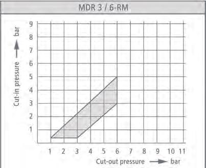
39 Pressure switch MDR 3 Pressure switch MDR 3 3-phase Switching capacity 7.5 (11) kw / 20 HP Available with overload relay Max. cut-out pressure 35 bar 3-pole (N.C.) Acc. to EN UL / CSA-approval optional Order reference Type code Unloader valves and cable glands for retrofitting, see accessories! ON / OFF Rotary knob Pressure range P OFF in bar Flange Weight (in g) Part No. MDR 3/6-EA MDR-3 DAA AAAA 045A060 XAA XXX EA 1,3-6 1/2" MDR 3/11-EA MDR-3 GAA AAAA 090A110 XAA XXX EA /2" MDR 3/11-EA MDR-3 GBA AAAA 090A110 XAA XXX EA /4" MDR 3/11-EA MDR-3 GEA AAAA 090A110 XAA XXX EA 4-11 F4 1/4" MDR 3/11-EA MDR-3 GDA AAAA 090A110 XAA XXX EA 4-11 F4 1/2" MDR 3/11-EA MDR-3 GFA AAAA 090A110 XAA XXX EA 4-11 F4 3/8" MDR 3/16-EA MDR-3 HAA AAAA 130A160 XAA XXX EA /2" MDR 3/16-EA MDR-3 HBA AAAA 130A160 XAA XXX EA /4" MDR 3/16-EA MDR-3 HEA AAAA 130A160 XAA XXX EA 6-16 F4 1/4" MDR 3/16-EA MDR-3 HDA AAAA 130A160 XAA XXX EA 6-16 F4 1/2" MDR 3/16-EA MDR-3 HFA AAAA 130A160 XAA XXX EA 6-16 F4 3/8" MDR 3/25-EA MDR-3 IAA AAAA 215A250 XAA XXX EA 7,5 25 1/2" MDR 3/25-EA MDR-3 IDA AAAA 215A250 XAA XXX EA 7,5 25 F4 1/2" MDR 3/35-EA MDR-3 JAA AAAA 320A350 XAA XXX EA /2" MDR 3/35-EA MDR-3 JDA AAAA 320A350 XAA XXX EA F4 1/2" MDR 3/6 MDR-3 DAA BAAA 045A060 XAA XXX - 1,3-6 1/2" MDR 3/11 MDR-3 GAA BAAA 090A110 XAA XXX /2" MDR 3/11 MDR-3 GBA BAAA 090A110 XAA XXX /4" MDR 3/11 MDR-3 GEA BAAA 090A110 XAA XXX F4 1/4" MDR 3/11 MDR-3 GDA BAAA 090A110 XAA XXX F4 1/2" MDR 3/11 MDR-3 GFA BAAA 090A110 XAA XXX F4 3/8" MDR 3/16 MDR-3 HAA BAAA 130A160 XAA XXX /2" MDR 3/16 MDR-3 HBA BAAA 130A160 XAA XXX /4" MDR 3/16 MDR-3 HEA BAAA 130A160 XAA XXX F4 1/4" MDR 3/16 MDR-3 HDA BAAA 130A160 XAA XXX F4 1/2" MDR 3/16 MDR-3 HFA BAAA 130A160 XAA XXX F4 3/8" MDR 3/25 MDR-3 IAA BAAA 215A250 XAA XXX - 7,5 25 1/2" MDR 3/25 MDR-3 IDA BAAA 215A250 XAA XXX - 7,5 25 F4 1/2" MDR 3/35 MDR-3 JAA BAAA 320A350 XAA XXX /2" MDR 3/35 MDR-3 JDA BAAA 320A350 XAA XXX F4 1/2" High performance Pressure switches Type overview Pressure Switch MDR 3 RM versions, with roller diaphragm - tight pressure differential, extended medium resistance Order reference Type code Unloader valves and cable glands for retrofitting, see accessories! ON / OFF Rotary knob Pressure range P OFF in bar Flange Weight (in g) Part No. MDR 3/6-RM MDR-3 DAB BAAA 028A035 XAA XXX - 1,3-6 1/2" MDR 3/11-RM MDR-3 GAB BAAA 060A070 XAA XXX /2" MDR 3/11-RM MDR-3 GOB BAAA 060A070 XAA XXX /2"+1/4" MDR 3/11-RM-EA MDR-3 GAB AAAA 060A070 XAA XXX EA /2" MDR 3/11-RM-EA MDR-3 GOB AAAA 060A070 XAA XXX EA /2"+1/4" MDR 3/16-RM MDR-3 HAB BAAA 145A160 XAA XXX /2" MDR 3/16-RM MDR-3 HOB BAAA 145A160 XAA XXX /2"+1/4" MDR 3/16-RM-EA MDR-3 HAB AAAA 145A160 XAA XXX EA /2" MDR 3/16-RM-EA MDR-3 HOB AAAA 145A160 XAA XXX EA /2"+1/4"
40 Pressure switch MDR 3 Technical Data MDR 3 acc. to EN 60947, UL / CSA Rated insulation voltage U i Motor switching capacity (UL 508, CSA 22.2) U e =120 V (1~) Motor switching capacity (AC3) U e =240 V (1~) Motor switching capacity (UL 508, CSA 22.2) U e =240 V (1~) Motor switching capacity (AC 3) U e =240 V (3~) Motor switching capacity (UL 508, CSA 22.2) U e =240 V (3~) Motor switching capacity (AC 3) U e =400 V (3~) Motor switching capacity (UL 508, CSA 22.2) U e =480 V (3~) Motor switching capacity (AC 3) U e =500 V (3~) Motor switching capacity (UL 508, CSA 22.2) U e =600 V (3~) Motor switching capacity (AC 3) U e =690 V (3~) 690 V 2 HP 5,5 kw 3 HP 5,5 kw 7,5 HP 7,5/11* kw 15 HP 7,5/11* kw 20 HP 7,5/15* kw Technical Data MDR 3 acc. to EN 60947, UL / CSA Schaltstücklebensdauer (AC 3) Schaltspiele > 1 x 10 5 Mechanische Lebensdauer Schaltspiele > 1 x 10 6 Max. Schalthäufigkeit elektrisch Schaltspiele/h 120 Max. Schalthäufigkeit mechanisch Schaltspiele/h 600 Bemessungsbetriebsstrom I e bei 690 V AC 3 24 A Berstdruck Pz < 16 > 40 bar > 25 > 60 bar Zul. Medientemperatur Luft C Zul. Medientemperatur Wasser + 80 C Schutzart nach EN IP 54 Anschlussquerschnitte 1 feindrähtig 1 x / 2 x 4 / 2,5 mm 2 Anschlussquerschnitte 1 eindrähtig 1 x / 2 x 6 / 4 mm 2 Air, Water Diaphragm media resistance MDR 3 resistant Diaphragm media resistance MDR 3 USA Acetylene, Gasoline, Butane, Diesel, Natural gas, Petroleum, Ethylene glycol, Glycerol, Fuel oil, Urine, Carbon dioxide, Carbonic acid, Air, Mineral oils, Vegetable oil, Propane, Silicon oil, Nitrogen, Synthetic oils, Water, Distilled water, Hydrogen, Sea water, Water steam resistant A detailed overview of diaphragm media resistance for all pressure switches can be found on page 22. Dimensions MDR 3 Pressure switch MDR-3 38

 Undervoltage release For all functions the neutral conductor is not necessary.")
41 Pressure switch MDR 3 Circuit Diagrams MDR 3 MDR 3 MDR 3 EA 3 R 3 RA 3 MDR 3 EA 3 R 3 RU 3 High performance Pressure switches MDR 3 EA 3 RA 3 MDR 3 EA 3 RU 3 MDR 3 EA 3 R 3 Accessory DPA-Board for MDR 3 (Use only with MDR-3..E/A and RU 3/400-SO; article-nr ) Description Installing the DPA - circuit board onto MDR 3, the pressure switch offers the following additional functions: Phase sequence control Phase failure detection Supervision of an external opener possible, e. g. Klixon for temperature supervision (clamp tension < 230 V) Undervoltage release For all functions the neutral conductor is not necessary. In case of malfunction the pressure switch will be switched off. Only upon solving the malfunction, the pressure switch can be switched on again. Field of application: place-variable compressors, building site-area etc. Order reference Description Voltage Packing (units) Part No. DPA-Board Phase sequence, phase drop protection board 400 V / 50 Hz Accessories Hourmeter kit MDR 3 Description The MDR 3 can be equipped or retrofitted with an operating hourmeter to monitor the pump and compressor running time. The hourmeter is available as a kit and can be attached to the cover in 4 different positions, each offset at an angle of 90. This ensures optimum readability. The kit consists of an operating hourmeter for either 230 V or 400 V and a perforated MDR 3 cover with or without ON/OFF lever. Order reference Description Voltage Packing (units) Part No. H3 - B 230 Hourmeter and Cover for MDR V / 50 Hz H3 - B 400 Hourmeter and Cover for MDR V / 50 Hz H3-EA - B 230 Hourmeter and Cover for MDR-3+EA 230 V / 50 Hz H3-EA - B 400 Hourmeter and Cover for MDR-3+EA 400 V / 50 Hz can be used at 60 Hz with higher engine speed 39
42 Pressure switch MDR 3 Accessories MDR 3 Order reference Description Weight (in g) Part No. Unloader valves EV 3 With screw connection for 6 mm plastic or copper discharge tubes EV 3i With screw connection for 1/4 plastic or copper discharge tubes EV 3S 1) 2) With quick-connect for 6 mm plastic discharge tubes EV 3W 1) 90 unloader valve with screw connection for 6 mm plastic or copper discharge tubes EV 3Wi 1) 90 unloader valve with screw connection for 1/4 plastic or copper discharge tubes EV 3WS 1) 2) 90 unloader valve with quick-connect for 6 mm plastic discharge tubes EV 3L With screw connection for 6 mm plastic or copper discharge tubes Delayed unloader valves AEV 3 With screw connection for 6 mm plastic or copper discharge tubes AEV 3S 1) 2) With quick-connect for 6 mm plastic discharge tubes AEV 3W 1) 90 unloader valve with screw connection for 6 mm plastic or copper discharge tubes AEV 3Wi 1) 90 unloader valve with screw connection for 1/4 plastic or copper discharge tubes AEV 3WS 1) 2) 90 unloader valve with quick-connect for 6 mm plastic discharge tubes Cable glands PG 9 Z With strain relief (for additional wiring) WN Grommet PG 11 G Conduits for mounting of cable glands (Inner thread) PG 11 V Cable gland complete PG 11 Z With strain relief PG 11 ZK With strain relief and cable support PG 13,5 G Conduits for mounting of cable glands (Inner thread) PG 13,5 V Cable gland complete PG 13,5 Z With strain relief PG 13,5 ZK With strain relief and cable support PG 16 G Conduits for mounting of cable glands (Inner thread) PG 16 V Cable gland complete PG 16 Z With strain relief PG 16 ZK With strain relief and cable support MW 3 Mounting bracket for MDR H3 (Cover MDR 3) H3-EA (Cover MDR 3+EA) Cover Cover without rotary knob (Neutral version, without marking) Cover with rotary knob for manual On/Off (Neutral version, without marking) Thermal, 3-pole overload relay SK 3 Arc-chamber without lock mechanism (supplied as standard with MDR 3...) SK 3-S SK 3-S Arc-chamber with lock mechanism (supplied as standard with MDR 3...+EA) SK R3/ 1,0 0,63 1,00 A SK R3/ 1,6 1,00 1,60 A SK R3/ 2,5 1,60 2,50 A SK R3/ 4,0 2,50 4,00 A SK R3/ 6,3 4,00 6,30 A SK R3/ 10,0 6,30 10,00 A SK R3/ 16,0 10,00 16,00 A SK R3/ 20,0 16,00 20,00 A SK R3/ 24,0 20,00 24,00 A SK R3/ 30/2 22,00 30,00 A, 2-polig Undervoltage and shunt releases RU 3/24-50 Undervoltage release 24 V, 50 Hz RU 3/ Undervoltage release 230 V, 50 Hz RU 3/ Undervoltage release 400 V, 50 Hz RA 3/24-50 Shunt release 24 V, 50 Hz RA 3/ Shunt release 110 V, 50 Hz RA 3/ Shunt release 230 V, 50 Hz RA 3/ Shunt release 240 V, 60 Hz RA 3/ Shunt release 400 V, 50 Hz RA 3/ Shunt release 480 V, 60 Hz ) up to < 16 bar 2) only for pneumatic tubes with outside tolerances according to e. g. Festo PAN 6x1mm


43 Pressure switch MDR 3 Unloader valves / Delayed unloader valves EV 3 / EV 3i EV 3S AEV 3S AEV 3 EV 3L High performance Pressure switches EV 3W / EV 3Wi AEV 3W / AEV 3Wi EV 3WS AEV 3WS Cable glands MDR 3 WN PG 9 Z PG.. G PG.. V PG.. Z PG.. ZK Wall-mounting bracket, 3-pole overload relay, undervoltage and shunt releases MW 3 SK 3 SK 3-S SK R3 /.. RU.. RA
44 Pressure switch MDR 3 Dimensions, Accessories MDR 3 EV 3 / EV 3i EV 3S AEV 3S AEV 3 EV 3L Tripping curves R3 (average) EV 3W / EV 3Wi AEV 3W / AEV 3Wi EV 3WS / AEV 3WS 42


45 Pressure switch MDR 3 Pressure Diagrams MDR 3 High performance Pressure switches 43
46 Pressure switch MDR 4 Pressure switch MDR 4 S 3-phase Switching capacity 4.0 / 5.5 kw Max. cut-out pressure 16 bar 3-pole (N.C.) Acc. to EN way-flange (optional) 44 Order reference Type code Unloader valves and cable glands for retrofitting, see accessories! ON / OFF Rotary knob Pressure range P OFF in bar Flange Weight (in g) Part No. MDR 4S/6-EA MDR-4 DBA AFAA 040A060 XAA XXX EA 1,5-6 1/4" MDR 4S/6-EA MDR-4 DAA AFAA 040A060 XAA XXX EA 1,5-6 1/2" MDR 4S/6-EA MDR-4 DOA AFAA 040A060 XAA XXX EA 1,5-6 1/2" + 1/4" MDR 4S/6-EA MDR-4 DEA AFAA 040A060 XAA XXX EA 1,5-6 F4 1/4" MDR 4S/6-EA MDR-4 DDA AFAA 040A060 XAA XXX EA 1,5-6 F4 1/2" MDR 4S/6-EA MDR-4 DFA AFAA 040A060 XAA XXX EA 1,5-6 F4 3/8" MDR 4S/11-EA MDR-4 GBA AFAA 090A110 XAA XXX EA /4" MDR 4S/11-EA MDR-4 GAA AFAA 090A110 XAA XXX EA /2" MDR 4S/11-EA MDR-4 GOA AFAA 095A110 XAA XXX EA /2" + 1/4" MDR 4S/11-EA MDR-4 GEA AFAA 090A110 XAA XXX EA 4-11 F4 1/4" MDR 4S/11-EA MDR-4 GDA AFAA 090A110 XAA XXX EA 4-11 F4 1/2" MDR 4S/11-EA MDR-4 GFA AFAA 090A110 XAA XXX EA 4-11 F4 3/8" MDR 4S/16-EA MDR-4 HBA AFAA 135A160 XAA XXX EA /4" MDR 4S/16-EA MDR-4 HAA AFAA 135A160 XAA XXX EA /2" MDR 4S/16-EA MDR-4 HOA AFAA 135A160 XAA XXX EA /2" + 1/4" MDR 4S/16-EA MDR-4 HEA AFAA 135A160 XAA XXX EA 6-16 F4 1/4" MDR 4S/16-EA MDR-4 HDA AFAA 135A160 XAA XXX EA 6-16 F4 1/2" MDR 4S/16-EA MDR-4 HFA AFAA 135A160 XAA XXX EA 6-16 F4 3/8" MDR 4S/25-EA MDR-4 IBA AFAA 210A250 XAA XXX EA 8,5-25 1/4" MDR 4S/25-EA MDR-4 IAA AFAA 210A250 XAA XXX EA 8,5-25 1/2" MDR 4S/25-EA MDR-4 IOA AFAA 210A250 XAA XXX EA 8,5-25 1/2" + 1/4" MDR 4S/25-EA MDR-4 IEA AFAA 210A250 XAA XXX EA 8,5-25 F4 1/4" MDR 4S/25-EA MDR-4 IDA AFAA 210A250 XAA XXX EA 8,5-25 F4 1/2" MDR 4S/25-EA MDR-4 IFA AFAA 210A250 XAA XXX EA 8,5-25 F4 3/8" MDR 4S/6 MDR-4 DBA BFAA 040A060 XAA XXX - 1,5-6 1/4" MDR 4S/6 MDR-4 DAA BFAA 040A060 XAA XXX - 1,5-6 1/2" MDR 4S/6 MDR-4 DOA BFAA 040A060 XAA XXX - 1,5-6 1/2" + 1/4" MDR 4S/6 MDR-4 DEA BFAA 040A060 XAA XXX - 1,5-6 F4 1/4" MDR 4S/6 MDR-4 DDA BFAA 040A060 XAA XXX - 1,5-6 F4 1/2" MDR 4S/6 MDR-4 DFA BFAA 040A060 XAA XXX - 1,5-6 F4 3/8" MDR 4S/11 MDR-4 GBA BFAA 090A110 XAA XXX /4" MDR 4S/11 MDR-4 GAA BFAA 090A110 XAA XXX /2" MDR 4S/11 MDR-4 GOA BFAA 095A110 XAA XXX /2" + 1/4" MDR 4S/11 MDR-4 GEA BFAA 090A110 XAA XXX F4 1/4" MDR 4S/11 MDR-4 GDA BFAA 090A110 XAA XXX F4 1/2" MDR 4S/11 MDR-4 GFA BFAA 090A110 XAA XXX F4 3/8" MDR 4S/16 MDR-4 HBA BFAA 135A160 XAA XXX /4" MDR 4S/16 MDR-4 HAA BFAA 135A160 XAA XXX /2" MDR 4S/16 MDR-4 HOA BFAA 135A160 XAA XXX /2" + 1/4" MDR 4S/16 MDR-4 HEA BFAA 135A160 XAA XXX F4 1/4" MDR 4S/16 MDR-4 HDA BFAA 135A160 XAA XXX F4 1/2" MDR 4S/16 MDR-4 HFA BFAA 135A160 XAA XXX F4 3/8" MDR 4S/25 MDR-4 IBA BFAA 210A250 XAA XXX - 8,5-25 1/4" MDR 4S/25 MDR-4 IAA BFAA 210A250 XAA XXX - 8,5-25 1/2" MDR 4S/25 MDR-4 IOA BFAA 210A250 XAA XXX - 8,5-25 1/2" + 1/4" MDR 4S/25 MDR-4 IEA BFAA 210A250 XAA XXX - 8,5-25 F4 1/4" MDR 4S/25 MDR-4 IDA BFAA 210A250 XAA XXX - 8,5-25 F4 1/2" MDR 4S/25 MDR-4 IFA BFAA 210A250 XAA XXX - 8,5-25 F4 3/8"
47 Pressure switch MDR Pressure switch MDR 4 SD 3-phase Switching capacity 4.0 / 5.5 kw Max. cut-out pressure 11 bar With scale and transparent cover 3-pole (N.C.) Acc. to EN Order reference Type code ON / OFF Rotary knob Pressure range P OFF in bar Flange Weight (in g) Part No. MDR 4 SD/6 MDR-4 DAA BFDA 040A060 XAA XXX - 1,5-6 1/2" MDR 4 SD/6 MDR-4 DBA BFDA 040A060 XAA XXX - 1,5-6 1/4" MDR 4 SD/11 MDR-4 GAA BFDA 090A110 XAA XXX /2" MDR 4 SD/11 MDR-4 GBA BFDA 090A110 XAA XXX /4" Unloader valves and cable glands for retrofitting, see accessories! High performance Pressure switches Pressure switch MDR 4 SU 3-phase Switching capacity 2.5 / 4.0 kw Max. cut-out pressure 16 bar With reversed function 3-pole (N.O.) Acc. to EN Order reference Type code ON / OFF Rotary knob Pressure range P OFF in bar Flange Weight (in g) Part No. MDR 4 SU/6 MDR-4 DAA BFCA 040A060 XAA XXX - 1,5-6 1/2" MDR 4 SU/11 MDR-4 GAA BFCA 090A110 XAA XXX /2" MDR 4 SU/16 MDR-4 HAA BFCA 090A110 XAA XXX /2" Unloader valves and cable glands for retrofitting, see accessories! 45
48 Pressure switch MDR 4 Technical Data MDR 4 S / MDR 4 SD acc. to EN Rated insulation voltage U i Motor switching capacity (AC 3) U e =240 V (1~) Motor switching capacity (AC 3) U e =230 V (3~) Motor switching capacity (AC 3) U e =400 V (3~) Motor switching capacity (AC 3) U e =500 V (3~) Electrical life (AC 3) U e =240 V (3~) Mechanical life Cycles Max. electrical cycles Cycles/h 500 V 2,5 kw 4,0 kw 5,5 kw 5,5 kw > 1 x 10 5 > 5 x Technical Data MDR 4 S / MDR 4 SD acc. to EN Max. mechanical cycles Cycles/h 600 Rated operational current I e at 400 V AC3/500 VAC 3 16 A / 9 A Bursting strength Pz > 35 bar Permissible medium temperature Air C Permissible medium temperature Water + 80 C Degree of Protection acc. to EN IP 44 Conductor cross-section 1 fine stranded cable 1 x / 2 x 2,5 / 2,5mm 2 Conductor cross-section 1 rigid cable 1 x / 2 x 2,5 / 2,5mm 2 Technical Data MDR 4 SU acc. to EN Rated insulation voltage U i Motor switching capacity (AC 3) U e =240 V (1~) Motor switching capacity (AC 3) U e =230 V (3~) Motor switching capacity (AC 3) U e =400 V (3~) Electrical life (AC 3) Cycles Mechanical life Cycles Max. electrical cycles Cycles/h Max. mechanical cycles Cycles/h Rated operational current I e at 400 V AC Bursting strength Pz 500 V 1,5 kw 2,5 kw 4,0 kw > 1 x 10 5 > 5 x A > 35 bar Technical Data MDR 4 SU acc. to EN Permissible medium temperature Air C Permissible medium temperature Water + 80 C Degree of Protection acc. to EN IP 44 Conductor cross-section 1 fine stranded cable 1 x / 2 x 2,5 / 2,5mm 2 Conductor cross-section 1 rigid cable 1 x / 2 x 2,5 / 2,5mm 2 Air, Water Diaphragm media resistance MDR 4 resistant A detailed overview of diaphragm media resistance for all pressure switches can be found on page 22.. Dimensions MDR 4 Pressure switch MDR 4 46
49 Pressure switch MDR 4 Circuit Diagrams MDR 4 MDR 4 S MDR 4 SD MDR 4 SU High performance Pressure switches Accessories MDR 4 Order reference Description Weight (in g) Part No Unloader valves EV 4 With screw connection for 6 mm plastic or copper discharge tubes EV 4S 1)2) With quick-connect for 6 mm plastic discharge tubes EV 4W 1) 90 with screw connection for 6 mm plastic or discharge copper tubes EV 4Wi 1) 90 with screw connection for 1/4" mm plastic or discharge copper tubes EV 4WS 1)2) 90 with quick-connect for 6 mm plastic discharge tubes Delayed unloader valves AEV 4 With screw connection for 6 mm plastic or copper discharge tubes AEV 4S 1)2) With quick-connect for 6 mm plastic discharge tubes AEV 4W 1) 90 with screw connection for 6 mm plastic or copper discharge tubes AEV 4Wi 1) 90 with screw connection for 1/4" mm plastic or copper discharge tubes AEV 4WS 1)2) 90 with quick-connect for 6 mm plastic discharge tubes Cable glands WN Grommet PG 11 G Conduits for mounting of cable glands (Inner thread) PG 11 V Cable gland complete PG 11 Z With strain relief PG 11 ZK With strain relief and cable support PG 13,5 G Conduits for mounting of cable glands (Inner thread) PG 13,5 V Cable gland complete PG 13,5 Z With strain relief PG 13,5 ZK With strain relief and cable support MW 4 Mounting bracket for MDR 4 and MDR H4 (Cover MDR 4S) H4S+EA (Cover MDR 4S+EA) H4SD (Cover MDR 4SD) Cover Cover without rotary knob (Neutral version, without marking) Cover with rotary knob for manual On/Off (Neutral version, without marking) Cover without rotary knob for MDR 4 SD (transparent) ) up to 16 bar, 2) only for pneumatic tubes with outside tolerances according to e. g. Festo PAN 6x1mm 47


50 Pressure switch MDR 4 Unloader valves / Delayed unloader valves EV 4 EV 4S AEV 4S AEV 4 EV 4W / EV 4Wi AEV 4W / AEV 4Wi EV 4WS AEV 4WS Wall-mounting bracket / Cable glands MDR 4 MW 4 WN PG.. G PG.. V PG.. Z PG.. ZK Dimensions, Accessories MDR 4 EV 4 EV 4S AEV 4S 48


51 Pressure switch MDR 4 Dimensions, Accessories MDR 4 EV 4 EV 4S AEV 4S High performance Pressure switches Pressure Diagrams MDR
52 Pressure switch MDR 5 Pressure switch MDR 5 3-phase Switching capacity 5.5 kw Available with overload relay Max. cut-out pressure 45 bar 3-pole (N.C.) Acc. to EN Order reference Type code ON / OFF Rotary knob Pressure range P OFF in bar Flange Weight (in g) Part No. MDR 5/5 MDR-5 CAA BAAA 015A030 XXX XXX - 1,5-5 1/2" MDR 5/5-K MDR-5 CAA AAAA 015A030 XXX XXX K* 1,5-5 1/2" MDR 5/5 MDR-5 COA BAAA 015A030 XXX XXX - 1,5-5 1/2" + 1/4" MDR 5/5-K MDR-5 COA AAAA 015A030 XXX XXX K* 1,5-5 1/2" + 1/4" MDR 5/8 MDR-5 EAA BAAA 070A080 XXX XXX /2" MDR 5/8-K MDR-5 EAA AAAA 070A080 XXX XXX K* 2-8 1/2" MDR 5/8 MDR-5 EOA BAAA 070A080 XXX XXX /2" + 1/4" MDR 5/8-K MDR-5 EOA AAAA 070A080 XXX XXX K* 2-8 1/2" + 1/4" MDR 5/11 MDR 5 GAA BAAA 090A110 XXX XXX /2" MDR 5/11-K MDR-5 GAA AAAA 090A110 XXX XXX K* /2" MDR 5/11 MDR-5 GOA BAAA 090A110 XXX XXX /2" + 1/4" MDR 5/11-K MDR-5 GOA AAAA 090A110 XXX XXX K* /2" + 1/4" MDR 5/16 MDR-5 HAA BAAA 130A160 XXX XXX - 2,5-16 1/2" MDR 5/16-K MDR-5 HAA AAAA 130A160 XXX XXX K* 2,5-16 1/2" MDR 5/16 MDR 5 HOA BAAA 130A160 XXX XXX - 2,5-16 1/2" + 1/4" MDR 5/16-K MDR-5 HOA AAAA 130A160 XXX XXX K* 2,5-16 1/2" + 1/4" MDR 5/45 MDR-5 KAA BAAA 300 A400 XXX XXX /2" MDR 5/45-K MDR-5 KAA AAAA 300 A400 XXX XXX K* /2" *For these switches, a thermal, 3-pole overload relay has to be ordered separately, the ON/OF mechanism will only work with an additional relay Unloader valves and cable glands for retrofitting, see accessories! Special execution IP 65 Applications: e.g. pump shafts 3-phase Switching capacity 5.5 kw Max. cut-out pressure 16 bar Incl. cable glands PG 16/13,5 ZK 3-pole (N.C.) Acc. to EN Degree of protection IP 65 Order reference Type code ON / OFF Rotary knob Pressure range P OFF in bar Flange Weight (in g) Part No. MDR 5/5 MDR-5 CAA BAAA 015A030 XNN XXZ - 1,5-5 1/2" MDR 5/8 MDR-5 EAA BAAA 070A080 XNN XXZ /2" MDR 5/11 MDR 5 GAA BAAA 090A110 XNN XXZ /2" MDR 5/16 MDR-5 HAA BAAA 130A160 XNN XXZ - 2,5-16 1/2"
53 Pressure switch MDR 5 Rated insulation voltage U i Motor switching capacity (AC 3) U e =240 V (1~) Motor switching capacity (AC 3) U e =230 V (3~) Motor switching capacity (AC 3) U e =400 V (3~) Motor switching capacity (AC 3) U e =500 V (3~) Electrical life (AC 3) Cycles Mechanical life Cycles Max. electrical cycles Cycles/h Max. mechanical cycles Cycles/h Rated operational current I e at 400 V AC 3 / 500 V AC 3 Technical Data MDR 5 acc. to EN V 2,5 kw 4,0 kw 5,5 kw 4,0 kw > 1 x 10 5 > 5 x A / 12 A Technical Data MDR 5 acc. to EN Bursting strength Pz up to 16 bar up to 45 bar > 40 bar > 60 bar Permissible medium temperature Air C Permissible medium temperature Water + 80 C Degree of Protection acc. to EN IP 54 / IP 65 Conductor cross-section 1 fine stranded cable 1 x / 2 x 2,5 / 2,5 mm 2 Conductor cross-section 1 rigid cable 1 x / 2 x 4 / 4 mm 2 Diaphragm media resistance MDR 5 Acetylene, Gasoline, Butane, Diesel, Natural gas, Petroleum, Ethylene glycol, Glycerol, Fuel oil, Urine, Carbon dioxide, Carbonic acid, Air, Mineral oils, resistant Vegetable oil, Propane, Silicon oil, Nitrogen, Synthetic oils, Water, Distilled water, Hydrogen, Sea water, Water steam A detailed overview of diaphragm media resistance for all pressure switches can be found in the table on page 22. High performance Pressure switches Dimensions MDR 5 Pressure switch MDR-5 MDR 5 MDR 5K R5 51


 H5-K (Cover MDR 5+K) Cover Cover")
54 Pressure switch MDR 5 Accessories MDR 5 Order reference Description Weight (in g) Part No. Unloader valves EV 5 With screw connection for 6 mm plastic or copper discharge tubes, screw connection for vent port EV 5i With screw connection for 1/4" plastic or copper discharge tubes EV 5E With screw connection for 6 mm plastic or copper discharge tubes EV 5Ei With screw connection for 1/4" plastic or copper discharge tubes Delayed unloader valves AEV 5 With screw connection for 6 mm plastic or copper discharge tubes AEV 5i With screw connection for 1/4" plastic or copper discharge tubes Cable glands WN M20 Grommet VS-M20 Screw plug M M20 Z With strain relief, clamping range 6-12 mm M20 ZK With strain relief and cable support, clamping range 6-12 mm M20 L With strain relief, clamping range mm M20 LK With strain relief and cable support, clamping range mm MW 5 Mounting bracket H5 (Cover MDR 5) H5-K (Cover MDR 5+K) Cover Cover without push-buttons Cover with On/Off push-buttons (Only functions together with the thermal R5 overload relay) Thermal, 3-pole overload relay R 5/1,5 0,86-1,50 A R 5/2,45 1,50-2,45 A R 5/4,2 2,40-4,20 A R 5/7,0 4,00-7,00 A R 5/10,3 6,10-10,3 A R 5/14,0 9,00-14,0 A R 5/18,0 11,0-18,0 A Unloader valves / Delayed unloader valves EV 5, EV 5i EV 5E / EV 5 Ei AEV 5 / AEV 5i Cable glands MDR 5 52 WN-M 20 VS M 20 M 20 Z / M20 L M 20 ZK / M 20 LK
55 Pressure switch MDR 5 Accessories, Miscellaneous MDR 5 MW 5 H5 H5-K R 5/.. High performance Pressure switches Dimensions, Accessories EV 4 EV 4S AEV 4S Tripping curves R5 (average) 53


56 Pressure switch MDR 5 Pressure Diagrams MDR 5 54

57 55
58 Control pressure switches Control pressure switches Industries MDR-F 1 SPDT / 2 DPDT Pressure range up to 250 bar ATEX / GL / VdS / UL approvals -optional Scale for simple adjustments Wide range of variations P. 57 Air pressure technology, water pressure technology, construction machinery, water-based extinguishing systems, fire protection units, oil pressure monitoring, mining, chemical, industry, railway vehicles, offshore, shipping, vacuum technology, calibration technology, heating systems MDR-P 1 SPDT Pressure range up to 16 bar Smallest pressure switch with coupling DIN EN Fixed pressure setting, OEM applications P. 70 Air pressure technology, water pressure technology, construction machinery, breweries, heating systems, calibration technology MDR-K 2 DPDT Pressure range up to 11 bar Bayonet coupling ISO OEM applications P. 73 Air pressure technology, water pressure technology MDR 43 1 N.O. + 1 N.C. Pressure range up to 16 bar P. 76 Air pressure technology, water pressure technology MDR 53 1 SPDT Maximum shut-off pressure setting 16 bar CSA approval optional Pressure adjustment without tools P. 78 Air pressure technology, water pressure technology 56

59 Control pressure switch MDR - F Control pressure switch MDR - F 1 SPDT / 2 DPDT Pressure range up to 250 bar ATEX / GL / VdS / UL approvals -optional Scale for simple adjustments Wide range of variations Acc. to EN Applications: Air pressure technology, water pressure technology, construction machinery, water-based extinguishing systems, fire protection units, oil pressure monitoring, mining, chemical, industry, railway vehicles, offshore, shipping, vacuum technology, calibration technology, heating systems Specific applied approval Application MDR F..H-S The Condor pressure switch series MDR-F can be universally used and are suitable for: Monitoring and controlling the pressure of liquids or gaseous media in pipelines, tanks, vats, pressure vessels and installations. Tasks in process control, cooling, pneumatics and hydraulics. Pressure monitoring of cooling circuits and lubrication systems on various types of machinery. Automatic switching of pump and compressor motors for supplying water to dwellings, booster pumps, fire-fighting equipment and on compressed air systems. Mode of operation: The pressure of the monitored medium operates against a diaphragm, bellows or a plunger all of which have different media resistance. Switching operation is carried out with the use of a micro switch ensuring flutter-free switching When the pressure reaches the upper switching point, the micro switch contacts change position. In normal cases e.g. a connected motor is switched off (up to 550 watts direct or using additional switches like a contactor etc.). Should the pressure fall below the lower switch point, then the micro switch contact returns to its default position and the motor is switched on. The upper and lower switching points can be set independently using a screw driver. Both switching points can be read off the scale. Pressure connection, pressure sensing element and electrical connections are all fitted on to a die-cast aluminum base. The sealable transparent, polycarbonate cover protects the scales and switch against environmental effects. Standard scope of delivery: rubber grommets MDR-F..H Die-cast aluminum flange MDR-F..Y Plastic flange (in particular for use in water technology applications) With industrial screw connection (Industrial clamp version available upon request) Control pressure switches Besides the standard types with Perbunan diaphragms, the following new types are available: Pressure switch with stainless steel pressure sensing element e.g. for liquid fuels, oils up to 200 C etc. High pressure switch with plastic plunger press. sensing element with stainless steel connection up to 250 bar Pressure switch with manual reset function and die-cast aluminum flange for oil, water and air etc. Pressure switch with Viton diaphragm and die-cast aluminum flange for increased media resistance Pressure switch with VdS approval for fire-extinguishing systems / fire protection-installations Pressure switch with GL approval for ship building and applications intended for use at sea Pressure switch with Atex approval in mining and chemicals plants that are at risk of explosion Pressure switch with UL approval for the North American market Vacuum DPDT The MDR-F pressure switch program is extended continuously. A current status of the existing designs and approvals is available on our homepage. 57
60 Control pressure switch MDR - F MDR-F standard version (Industrial cage clamp version) suffix G for gold-flashed contacts Pressure switch with Perbunan diaphragm and die-cast aluminum flange for oil, water and air etc. Connection: H G 3/8 inner thread Order reference Type Code Adjustable cut-in pressure (bar) Smallest pressure diff. (bar)* Adjustable cutout pressure (bar) Weight (in g) Part No. MDR-F 2H-S MDR-F 2 HAA SAA A 005A015 0,04 1,89 0,07 0,11 0, MDR-F 2HG-S MDR-F 2 HAA SBA A 005A015 0,04 1,89 0,07 0,11 0, MDR-F 4H-S MDR-F 4 HAA SAA A 010A030 0,07 3,75 0,15 0,25 0, MDR-F 4HG-S MDR-F 4 HAA SBA A 010A030 0,07 3,75 0,15 0,25 0, MDR-F 8H-S MDR-F 8 HAA SAA A 020A060 0,2 7,5 0,3 0,5 0, MDR-F 8HG-S MDR-F 8 HAA SBA A 020A060 0,2 7,5 0,3 0,5 0, MDR-F 10H-S MDR-F 10 HAA SAA A 040A050 0,3 9,2 0,4 0,8 0, MDR-F 10HG-S MDR-F 10 HAA SBA A 040A050 0,3 9,2 0,4 0,8 0, MDR-F 16H-S MDR-F 16 HAA SAA A 040A120 0,4 15 0,6 1, MDR-F 16HG-S MDR-F 16 HAA SBA A 040A120 0,4 15 0,6 1, MDR-F 32H-S MDR-F 32 HAA SAA A 100A200 0,8 30 1,2 2, MDR-F 32HG-S MDR-F 32 HAA SBA A 100A200 0,8 30 1,2 2, * lower upper end of range MDR-F standard version with plastic flange (Industrial cage clamp version) suffix G for gold-flashed contacts Pressure switch with Perbunan diaphragm and plastic flange e.g. for demineralized water Pressure connection: Y G 3/8 inner thread Order reference Type Code Adjustable cut-in pressure (bar) Smallest pressure diff. (bar)* Adjustable cutout pressure (bar) Weight (in g) Part No. MDR-F 2Y-S MDR-F 2 YAA SAA A 005A015 0,04 1,89 0,07 0,11 0, MDR-F 2YG-S MDR-F 2 YAA SBA A 005A015 0,04 1,89 0,07 0,11 0, MDR-F 4Y-S MDR-F 4 YAA SAA A 010A030 0,07 3,75 0,15 0,25 0, MDR-F 4YG-S MDR-F 4 YAA SBA A 010A030 0,07 3,75 0,15 0,25 0, MDR-F 8Y-S MDR-F 8 YAA SAA A 020A060 0,2 7,5 0,3 0,5 0, MDR-F 8YG-S MDR-F 8 YAA SBA A 020A060 0,2 7,5 0,3 0,5 0, MDR-F 10Y-S MDR-F 10 YAA SAA A 040A050 0,3 9,2 0,4 0,8 0, MDR-F 10YG-S MDR-F 10 YAA SBA A 040A050 0,3 9,2 0,4 0,8 0, MDR-F 16Y-S MDR-F 16 YAA SAA A 040A120 0,4 15 0,6 1, MDR-F 16YG-S MDR-F 16 YAA SBA A 040A120 0,4 15 0,6 1, * lower upper end of range MDR-F stainless steel pressure transducing element version with pressure connection (Industrial cage clamp version) suffix G for gold-flashed contacts Pressure switch with stainless steel press. sensing element e.g. for liquid fuels, oils up to 200 C etc. / Connection: HE G 1/4 inner thread Order reference * lower upper end of range Type Code Adjustable cut-in pressure (bar) Smallest pressure diff. (bar)* Adjustable cutout pressure (bar) Weight (in g) Part No. MDR-F 12HE-S MDR-F 12 HEC SAA A 060A070 0,5 11,2 0,5 0, MDR-F 12HEG-S MDR-F 12 HEC SBA A 060A070 0,5 11,2 0,5 0, MDR-F 30HE-S MDR-F 30 HEC SAA A 160A ,4 3,0 3, MDR-F 30HEG-S MDR-F 30 HEC SBA A 160A ,4 3,0 3,
61 Control pressure switch MDR - F MDR-F high-pressure switch version (Industrial cage clamp version) suffix G for gold-flashed contacts High pressure switch with plastic plunger press. sensing element with stainless steel connection up to 250 bar Pressure connection: HH G 3/8 inner thread Order reference Type Code Adjustable cut-in pressure (bar) Smallest pressure diff. (bar)* Adjustable cutout pressure (bar) Weight (in g) Part No. MDR-F 60HH-S MDR-F 60 HHA SAA A 200A MDR-F 60HHG-S MDR-F 60 HHA SBA A 200A MDR-F 120HH-S MDR-F 120 HHA SAA A 200A MDR-F 120HHG-S MDR-F 120 HHA SBA A 200A MDR-F 250HH-S MDR-F 250 HHA SAA A 100B MDR-F 250HHG-S MDR-F 250 HHA SBA A 100B * lower upper end of range MDR-F version with reset function (Hmin / Hmax and Htro) (Industrial cage clamp version) Pressure switch with reset function and die-cast aluminum flange for oil, water and air etc. Pressure connection: H G 3/8 inner thread DIN ISO 228/I, VDE 0660, IEC 337-1, IEC MDR-F.. Hmax (SPDT with manual reset max.) When pressure rises above the upper setting value, contact opens and contact closes and latches. When the pressure falls bellow the upper setting value, the contact can be released with the manual reset button. MDR-F.. Hmin (SPDT with manual reset min.) After pressure rises above the lower setting value, the function is activated by pressing the manual reset button. When the pressure falls, contact closes and opens contact when reaching the lower cut-in value. Since the upper switching point (cut-out pressure) of the reset pressure switch must lie above the maximum cut-out pressure of the apparatus, the switching state remains until the manual reset button is pressed again. MDR-F.. Htro (SPDT with manual reset as run-dry protection) Typically, the switch is connected in series with the control circuit. For pressure increase, the manual reset button must be held until the pressure lies beyond the monitoring point. When the pressure falls below the monitoring point, contact closes and contact opens. When the pressure automatically rises above 10% of the monitored pressure, contact opens and contact closes again automatically, otherwise, a restart using the manual reset button must be carried out again. NOTICE: Should there not be a rise in pressure when pressing the button, discontinue pressing the button as a fault in the system must be present. Control pressure switches Order reference Type Code Adjustable cut-in pressure (bar) Smallest pressure diff. (bar)* Adjustable cutout pressure (bar) Weight (in g) Part No. MDR-F 2Hmax-S MDR-F 2 HAA SAH A XXXA , MDR-F 4Hmax-S MDR-F 4 HAA SAH A XXXA , MDR-F 8Hmax-S MDR-F 8 HAA SAH A XXXA , MDR-F 10Hmax-S MDR-F 10 HAA SAH A XXXA , MDR-F 16Hmax-S MDR-F 16 HAA SAH A XXXA MDR-F 32Hmax-S MDR-F 32 HAA SAH A XXXA MDR-F 2Hmin-S *1 MDR-F 2 HAA SAL A 005A015 0,04 1,89 0,07 0,11 0, MDR-F 4Hmin-S *1 MDR-F 4 HAA SAL A 010A030 0,07 3,75 0,15 0,25 0, MDR-F 8Hmin-S *1 MDR-F 8 HAA SAL A 020A060 0,2 7,5 0,3 0,5 0, MDR-F 10Hmin-S *1 MDR-F 10 HAA SAL A 025A075 0,3 9,2 0,4 0,8 0, MDR-F 16Hmin-S *1 MDR-F 16 HAA SAL A 040A120 0,4 15 0,6 1, MDR-F 32Hmin-S *1 MDR-F 32 HAA SAL A 080A240 0,8 30 1,2 2, MDR-F 2Htro-S MDR-F 2 HAA SAG A 005AXXX 0,04 1, MDR-F 4Htro-S MDR-F 4 HAA SAG A 010AXXX 0,07 3, MDR-F 8Htro-S MDR-F 8 HAA SAG A 020AXXX 0,2 7, MDR-F 10Htro-S MDR-F 10 HAA SAG A 025AXXX 0,3 9, MDR-F 16Htro-S MDR-F 16 HAA SAG A 040AXXX 0, MDR-F 32Htro-S MDR-F 32 HAA SAG A 080AXXX 0, * lower upper end of range *1 The minimum-pressure to be overseen and the operating-pressure must be in the pressure-spectrum of the cut-in-pressure. Additional MDR-F pressure switch versions.. Reset function are available on request (e.g. as stainless steel bellows version, with gold-flashed contacts, as high pressure switch etc.). 59
62 Control pressure switch MDR - F MDR-F version with Viton membrane (Industrial cage clamp version) Pressure switch with Viton diaphragm and die-cast aluminum flange for enhanced media resistance Pressure connection: H G 3/8 inner thread Order reference Type Code Adjustable cut-in pressure (bar) Smallest pressure diff. (bar)* Adjustable cutout pressure (bar) Additional MDR-F pressure switch versions MDR-F..HV are available on request (e. g. with reset function, with gold-flashed contacts, with plastic flange etc.) Weight (in g) Part No. MDR-F 2HV-S MDR-F 2 HVA SAA A 005A015 0,04 1,89 0,07 0,11 0, MDR-F 4HV-S MDR-F 4 HVA SAA A 010A030 0,07 3,75 0,15 0,25 0, MDR-F 8HV-S MDR-F 8 HVA SAA A 020A060 0,2 7,5 0,3 0,5 0, MDR-F10 HV-S MDR-F 10 HVA SAA A 040A050 0,3 9,2 0,4 0,8 0, MDR-F 16HV-S MDR-F 16 HVA SAA A 040A120 0,4 15 0,6 1, MDR-F 32HV-S MDR-F 16 HVA SAA A 100A200 0,8 30 1,2 2, * lower upper end of range VdS pressure switches for water extinguishing systems / fire-fighting equipments These pressure switches are primarily conceived for the use in firmly installed water extinguishing systems / fire-fighting equipments and approved from the VdS damage-prevention under the NO. G In particular, selective examinations, the request-profiles, the quality and the functionality intensively are tested. Dependent on the use there are: Alarm pressure switches (MDR-F 2 VdS ), which are manufactured with a pressure range from 0,35 to 1 bar with minimal difference, and Pressure switches (MDR-F X VdS ), with 10, 12.5 or 16 bar set for X, which limit the maximum pressure difference between cut-in and cut-out pressure to 1,5 bar. As MDR-F VdS with reset function, standard only the alarm pressure switch is as max.-reset listed. However, it is all VdS pressure switch with each reset function (see overview MDR-F with reset function), alternatively a Viton diaphragm and / or also a flange with 3/8" inner-screw threads on inquiry available. Moreover, customer-specific boards with own circuits and LED in integrated design are available as well as realisable. Further information can be seen on our homepage: Please take into account that the use of the pressure switch with plastic flange is restricted up to 10 bar. MDR-F VdS version for water-based extinguishing systems / fire protection (Industrial cage clamp version) Pressure switch with Perbunan diaphragm and die-cast aluminum flange for water extinguishing systems / fire-fighting equipments Pressure connection: H G 1/2 inner thread Order reference Type Code Adjustable cut-in pressure (bar) Smallest pressure diff. (bar)* Adjustable cutout pressure (bar) Weight (in g) Part No. MDR-F 2H-S VdS MDR-F 2 HAB SAA A XXXA007 A 0,1 0, MDR-F 2Hmax-S VdS MDR-F 2 HAB SAH A XXXA007 A 0,1 0, MDR-F 10H-S VdS MDR-F 10 HAB SAA A 040A050 A 0,3 9,2 0,4 1,5 0, MDR-F 12H-S VdS MDR-F 12 HAB SAA A 080A090 A 0,4 11 0,6 1,5 1 12, MDR-F 16H-S VdS MDR-F 16 HAB SAA A 110A120 A 0,4 15 0,6 1, Type overview MDR-F.. Y VdS (Industrial cage clamp version) Pressure switch with Perbunan diaphragm and die-cast aluminum flange for water extinguishing systems / fire-fighting equipments Pressure connection: H G 1/2 inner thread Order reference Type Code Adjustable cut-in pressure (bar) Smallest pressure diff. (bar)* Adjustable cutout pressure (bar) Weight (in g) Part No. MDR-F 2Y-S VdS MDR-F 2 YAB SAA A XXXA007 A 0,1 0, MDR-F 2Ymax-S VdS MDR-F 2 YAB SAH A XXXA007 A 0,1 0, MDR-F 10Y-S VdS MDR-F 10 YAB SAA A 040A050 A 0,2 9,2 0,4 1,5 0,
63 Control pressure switch MDR - F GL Pressure Switch for Ship Building and Applications Intended for Use at Sea These pressure switches are mostly used in the field of shipping technology, particularly in ship and plant engineering, and are approved by GL (Germanischer Llyod); one of the largest classification societies in the field of shipping, under No HH. The requirement profiles, quality and functionality have been intensively tested by means of specialized, demanding tests. Our GL pressure switches can be used up to a maximum of 250 bar. Pressure switches fitted with plastic flanges are approved up to 12.5 bar. All GL pressure switches can also be fitted with a reset button. Because of the variety of possible pressure switch configurations, please feel free to simply contact us if you have queries regarding special applications or technical requests. MDR-F GL version for shipbuilding and seaworthy applications (Industrial cage clamp version) Pressure switch with Perbunan diaphragm and die-cast aluminum flange, GL cable gland Pressure connection: G 3/8" Order reference * lower upper end of range Type Code Adjustable cut-in pressure (bar) Smallest pressure diff. (bar)* Adjustable cutout pressure (bar) Weight (in g) Part No. MDR-F 2H-S GL MDR-F 2 HAA SAA H 005A015 G 0,04 1,89 0,07 0,11 0, MDR-F 4H-S GL MDR-F 4 HAA SAA H 010A030 G 0,07 3,75 0,15 0,25 0, MDR-F 8H-S GL MDR-F 8 HAA SAA H 020A060 G 0,2 7,5 0,3 0,5 0, MDR-F 10H-S GL MDR-F 10 HAA SAA H 040A050 G 0,3 9,2 0,4 0,8 0, MDR-F 12H-S GL MDR-F 12 HAA SAA H 080A090 G 0,4 11 0,6 1,5 1 12, MDR-F 16H-S GL MDR-F 16 HAA SAA H 040A120 G 0,4 15 0,6 1, MDR-F 32H-S GL MDR-F 32 HAA SAA H 100A200 G 0,8 30 1,2 2, Control pressure switches Type overview MDR-F.. HH..GL High pressure switch with plastic plunger press. sensing element (Industrial cage clamp version) with stainless steel connection up to 250 bar, GL Cable gland. Connection: HH G 3/8 inner thread Order reference * lower upper end of range Type Code Adjustable cut-in pressure (bar) Smallest pressure diff. (bar)* Adjustable cutout pressure (bar) Weight (in g) Part No. MDR-F 60HH-S GL MDR-F 60 HHA SAA H 200A400 G 4 52 bar bar MDR-F 120HH-S GL MDR-F 120 HHA SAA H 200A800 G bar bar MDR-F 250HH-S GL MDR-F 250 HHA SAA H 100B200 G bar bar
64 Control pressure switch MDR - F MDR-F ATEX version in explosion-risk units for mining and chemical industries The pressure switch MDR-F serves as a on and off switch for intrinsically safe circuits dependant upon the pressure of various media. This switch can be used in firedamp-susceptible mines, explosive gas atmospheres and explosive dust atmospheres. (Groups I, II, III) Because we, as a recognized Atex production plant, are able to manufacture pressure switches with a wide variety of configurations, please feel free to simply contact us if you have queries regarding special applications or technical requests. Application: Mining (firedamp, coal dust) Ex I M2 Ex ia I Mb Type overview MDR-F.. JG Ex Pressure switch with NBR diaphragm and zinc die-cast flange Pressure connection: G 3/8" inner thread, plastic cover Order reference Type Code Adjustable cut-in pressure (bar) Smallest pressure diff. (bar)* Adjustable cutout pressure (bar) Weight (in g) Part No. MDR-F 2JG-S Ex I M2 MDR-F 2 JAA SBA J 005A015 B2XX ---1pce.a 0,04 1,89 0,07 0,11 0, MDR-F 4JG-S Ex I M2 MDR-F 4 JAA SBA J 010A030 B2XX ---1pce.a 0,07 3,75 0,15 0,25 0, MDR-F 8JG-S Ex I M2 MDR-F 8 JAA SBA J 020A060 B2XX ---1pce.a 0,2 7,5 0,3 0,5 0, MDR-F 10JG-S Ex I M2 MDR-F 10 JAA SBA J 040A050 B2XX ---1pce.a 0,3 9,2 0,4 0,8 0, MDR-F 16JG-S Ex I M2 MDR-F 16 JAA SBA J 040A120 B2XX ---1pce.a 0,4 15 0, MDR-F 32JG-S Ex I M2 MDR-F 32 JAA SBA J 100A200 B2XX ---1pce.a 0,8 30 1, Type overview MDR-F.. JHG Ex High-pressure switch with plastic plunger and stainless steel and zinc die-cast flange Pressure connection: G 3/8" inner thread with choke, plastic cover Order reference Type Code Adjustable cut-in pressure (bar) Smallest pressure diff. (bar)* Adjustable cutout pressure (bar) Weight (in g) Part No. MDR-F 60JHG-S Ex I M2 MDR-F 60 JHA SBA J 200A400 B2XX ---1pce.a MDR-F 120JHG-S Ex I M2 MDR-F 120 JHA SBA J 200A800 B2XX ---1pce.a MDR-F 250JHG-S Ex I M2 MDR-F 250 JHA SBA J 100B200 B2XX ---1pce.a Type overview MDR-F.. JEG Ex Pressure switch with stainless steel pressure transducer with stainless steel and zinc die-cast flange Pressure connection: G 1/4" inner thread, plastic cover Order reference Type Code Adjustable cut-in pressure (bar) Smallest pressure diff. (bar)* Adjustable cutout pressure (bar) Weight (in g) Part No. MDR-F 12JEG-S Ex I M2 MDR-F 12 JEC SBA J 060A070 B2XX ---1pce.a 0,5 11,2 0,5 0, MDR-F 30JEG-S Ex I M2 MDR-F 30 JEC SBA J 160A200 B2XX ---1pce.a 1 26,4 3,0 3, Type overview MDR-F.. JG Ex for Vacuum monitoring Pressure switch with Perbunan diaphragm and die-cast aluminum flange Pressure connection: H G 1/4 inner thread, plastic cover Order reference Type Code Adjustable cut-in pressure (bar) Smallest pressure diff. (bar)* Adjustable cutout pressure (bar) Weight (in g) Part No. MDR-F 03JG-S Ex I M2 MDR-F 03 JAC SBA J 010V030 B2XX ---1pce.a -0,9 0,15 0,15-0,75 0, MDR-F 3JG-S Ex I M2 MDR-F 3 JAC SBA J 100V150 B2XX ---1pce.a -0,9 2,6 0,2 0,4-0,
65 Control pressure switch MDR - F Application: Industry (gases, fumes) Ex II 2G Ex ia IIC T6 Gb and industry (dust) Ex II 2D Ex ia IIIC T85 Db Type overview MDR-F.. HG Ex Pressure switch with NBR diaphragm and aluminium die-cast flange Pressure connection: G 3/8" inner thread, aluminium die-cast cover Order reference Type Code Adjustable cut-in pressure (bar) Smallest pressure diff. (bar)* Adjustable cutout pressure (bar) Weight (in g) Part No. MDR-F 2HG-S Ex II 2 G/D MDR-F 2 HAA SBA J 005A015 C2XX ---1pce.a 0,04 1,89 0,07 0,11 0, MDR-F 4HG-S Ex II 2 G/D MDR-F 4 HAA SBA J 010A030 C2XX ---1pce.a 0,07 3,75 0,15 0,25 0, MDR-F 8HG-S Ex II 2 G/D MDR-F 8 HAA SBA J 020A060 C2XX ---1pce.a 0,2 7,5 0,3 0,5 0, MDR-F 10HG-S Ex II 2 G/D MDR-F 10 HAA SBA J 040A050 C2XX ---1pce.a 0,3 9,2 0,4 0,8 0, MDR-F 16HG-S Ex II 2 G/D MDR-F 16 HAA SBA J 040A120 C2XX ---1pce.a 0,4 15 0, MDR-F 32HG-S Ex II 2 G/D MDR-F 32 HAA SBA J 100A200 C2XX ---1pce.a 0,8 30 1, Type overview MDR-F.. HHG Ex High-pressure switch with plastic plunger and stainless steel and aluminium die-cast flange Pressure connection: G 3/8" inner thread with choke, aluminium die-cast cover Order reference Type Code Adjustable cut-in pressure (bar) Smallest pressure diff. (bar)* Adjustable cutout pressure (bar) Weight (in g) Part No. MDR-F 60HHG-S Ex II 2 G/D MDR-F 60 HHA SBA J 200A400 C2XX ---1pce.a MDR-F 120HHG-S Ex II 2 G/D MDR-F 120 HHA SBA J 200A800 C2XX ---1pce.a MDR-F 250HHG-S Ex II 2 G/D MDR-F 250 HHA SBA J 100B200 C2XX ---1pce.a Control pressure switches Type overview MDR-F.. HEG Pressure switch with stainless steel pressure transducer with stainless steel and aluminium die-cast flange Pressure connection: G 1/4" inner thread, aluminium die-cast cover Order reference Type Code Adjustable cut-in pressure (bar) Smallest pressure diff. (bar)* Adjustable cutout pressure (bar) Weight (in g) Part No. MDR-F 12HEG-S Ex II 2 G/D MDR-F 12 HEC SBA J 060A070 C2XX ---1pce.a 0,5 11,2 0,5 0, MDR-F 30HEG-S Ex II 2 G/D MDR-F 30 HEC SBA J 160A200 C2XX ---1pce.a 1 26,4 3,0 3, Type overview MDR-F.. HG Ex for monitoring vacuum Pressure switch with NBR diaphragm and aluminium die-cast flange Pressure connection: G 1/4" inner thread, aluminium die-cast cover Order reference Type Code Adjustable cut-in pressure (bar) Smallest pressure diff. (bar)* Adjustable cutout pressure (bar) Weight (in g) Part No. MDR-F 03HG-S Ex II 2 G/D MDR-F 03 HAC SBA J 010V030 C2XX ---1pce.a -0,9 0,15 0,15-0,75 0, MDR-F 3HG-S Ex II 2 G/D MDR-F 3 HAC SBA J 100V150 C2XX ---1pce.a -0,9 2,6 0,2 0,4-0,
66 Control pressure switch MDR - F MDR-F UL version for the North American market Pressure switches are designed for the North American market and were approved by Underwriters Laboratories, Inc. (UL) under the approval number E During special high-demanding examinations, requirements, quality and functionality were tested intensively. Due to the variety of possible pressure switch versions, please simply contact us for questions about special applications or technical requests. Type overview MDR-F.. H UL Pressure switch with NBR diaphragm and aluminium die-cast flange Pressure connection: G 3/8" inner thread Order reference Type Code Adjustable cut-in pressure (bar) Smallest pressure diff. (bar)* Adjustable cutout pressure (bar) Weight (in g) Part No. MDR-F 2H-S UL MDR-F 2 HAA SAA A 008D020 EXXX ---1pce.a 0, , MDR-F 4H-S UL MDR-F 4 HAA SAA A 015D040 EXXX ---1pce.a MDR-F 8H-S UL MDR-F 8 HAA SAA A 030D060 EXXX ---1pce.a MDR-F 10H-S UL MDR-F 10 HAA SAA A 060D075 EXXX ---1pce.a MDR-F 16H-S UL MDR-F 16 HAA SAA A 080D160 EXXX ---1pce.a MDR-F 32H-S UL MDR-F 32 HAA SAA A 145D290 EXXX ---1pce.a Type overview MDR-F.. HH UL Pressure switch with stainless steel pressure transducer with stainless steel and aluminium die-cast flange Pressure connection: G 3/8" inner thread with choke Order reference Type Code Adjustable cut-in pressure (bar) Smallest pressure diff. (bar)* Adjustable cutout pressure (bar) Weight (in g) Part No. MDR-F 60HH-S UL MDR-F 60 HHA SAA A 290D580 EXXX ---1pce.a MDR-F 120HH-S UL MDR-F 120 HHA SAA A 058E116 EXXX ---1pce.a MDR-F 250HH-S UL MDR-F 250 HHA SAA A 145E290 EXXX ---1pce.a Type overview MDR-F.. H UL for monitoring vacuum Pressure switch with NBR diaphragm and aluminium die-cast flange Pressure connection: G 1/4" inner thread, aluminium die-cast cover Order reference Type Code Adjustable cut-in pressure (bar) Smallest pressure diff. (bar)* Adjustable cutout pressure (bar) Weight (in g) Part No. MDR-F 03H-S UL MDR-F 03 HAC SAA A 010V030 EXXX ---1pce.a -0,9 0,15 0,15-0,75 0, MDR-F 3H-S UL MDR-F 3 HAC SAA A 100V150 EXXX ---1pce.a -0,9 2,6 0,2 0,4-0,
67 Control pressure switch MDR - F MDR-F vacuum monitoring version These pressure switches can be used as vacuum switches for compressible materials (gases), but also for liquids, within the normal pressure range. They have been designed primarily for use in the rough vacuum range (technical vacuum) and are distinguished by their small pressure differences and high level of switching precision. Their range of application includes, for example, the fields of automation, transportation, heating, climate-control and ventilation. They offer universal application potential as openers, closers or changers. Type overview MDR-F.. H (G) for Vacuum monitoring, suffix G for gold-flashed contacts Pressure switch with Perbunan diaphragm and die-cast aluminum flange for oil, water and air etc. Pressure connection: H G 1/4 inner thread Order reference Type Code Adjustable cut-in pressure (bar) Smallest pressure diff. (bar)* Adjustable cutout pressure (bar) Weight (in g) Part No. MDR-F 03H-S MDR-F 03 HAC SAA A 010V030 XXXX -0,9... 0, MDR-F 03HG-S MDR-F 03 HAC SBA A 010V030 XXXX -0,9... 0, MDR-F 3H-S MDR-F 3 HAC SAA A 100V150 XXXX -0, , MDR-F 3HG-S MDR-F 3 HAC SBA A 100V150 XXXX -0, , MDR-F DPDT version Control pressure switches This pressure switch is characterized by be equipped with a DPDT. As a result, the switch is even more flexible in its range of applications. Due to the variety of possible pressure switch versions, please simply contact us for questions about special applications or technical requests. Type overview MDR-F.. H LF Pressure switch with NBR diaphragm and aluminium die-cast flange for oil, water and air etc. Pressure connection: G 3/8" inner thread Order reference Type Code Adjustable cut-in pressure (bar) Smallest pressure diff. (bar)* Adjustable cutout pressure (bar) Weight (in g) Part No. MDR-F 2H-2W-S MDR-F 2 HAA LFA D 005A015 XXXX ---1pce.a MDR-F 4H-2W-S MDR-F 4 HAA LFA D 010A030 XXXX ---1pce.a MDR-F 8H-2W-S MDR-F 8 HAA LFA D 020A060 XXXX ---1pce.a MDR-F 10H-2W-S MDR-F 10 HAA LFA D 040A050 XXXX ---1pce.a MDR-F 16H-2W-S MDR-F 16 HAA LFA D 040A120 XXXX ---1pce.a , MDR-F 32H-2W-S MDR-F 32 HAA LFA D 100A200 XXXX ---1pce.a Type overview MDR-F.. H LF Pressure switch with NBR diaphragm and plastic flange, for example, for purified water Pressure connection: G 3/8" inner thread Order reference Type Code Adjustable cut-in pressure (bar) Smallest pressure diff. (bar)* Adjustable cutout pressure (bar) Weight (in g) Part No. MDR-F 2Y-2W-S MDR-F 2 YAA LFA D 005A015 XXXX ---1pce.a MDR-F 4Y-2W-S MDR-F 4 YAA LFA D 010A030 XXXX ---1pce.a MDR-F 8Y-2W-S MDR-F 8 YAA LFA D 020A060 XXXX ---1pce.a MDR-F 10Y-2W-S MDR-F 10 YAA LFA D 040A050 XXXX ---1pce.a MDR-F 16Y-2W-S MDR-F 16 YAA LFA D 040A120 XXXX ---1pce.a ,
68 Control pressure switch MDR - F Technical data MDR-F standard version Rated operational current I e AC 1 U e =240 V (1~) Rated operational current I e AC 15 U e =240 V (1~) Rated operational current Ie DC 13 U e =240 V (1~) Permissible motor rating 1~ 230 V Motor switching capacity (UL 508, CSA 22.2) U e =125 VAC Motor switching capacity (UL 508, CSA 22.2) U e =250 VAC Rated operational current I e (UL 508, CSA 22.2) U e =250 VAC Rated operational current I e (UL 508, CSA 22.2) U e =12 VDC 10 A 4 A 0,1 A 0,55 kw 0,5 HP 0,5 HP 15 A 6 A Technical data MDR-F Ex Maximum switching voltage U i Maximum switching strength I i Maximum internal capacity C i Maximum internal conductivity I i Ambient temperature T a 200 V 3 A negligible negligible -30 C Ta +65 C Only for connection to a separately examined and certified intrinsically safe circuit in the protection type: Ex ia I Mb (MDR-F JG Ex) Ex ia IIC Ex ia IIA, IIB, IIC T6 Gb (MDR-F HG Ex) Ex ia IIIC T85 C Db (MDR-F HG Ex) Technical data MDR-F..(G) - gold-flashed contact Rated operational current I e Ue=30 V (1~) 400 ma Permissible motor rating 1~ 30 V 12 VA Motor switching capacity (UL 508, CSA 22.2) U e = VAC 0,5 HP Rated operational current I e (UL 508, CSA 22.2) U e =250 VAC 10 A Rated operational current I e (UL 508, CSA 22.2) Ue=12 VDC 6 A Technical data MDR-F Vibration resistance 10 bis 1000 Hz 4 g Degree of protection acc. to DIN /IEC 529 With rubber grommets IP 54 Degree of protection acc. to DIN /IEC 529 With cable glands M20 IP 65 Ambient temperature range - 20 C C Cross-sections Cage clamp (without cable end sleeve) 1,5 mm² Cross-sections Screw clamp 2,5 mm² Technical data MDR-F Perm. media temperature: MDR-F..H / HH MDR-F..HV MDR-F..HE MDR-F..Y Repeatability + 70 C C C + 50 C <2% FS Attention: Please, regard the MDR-F instructions enclosing the pressure switch for the max. operating pressure and the max. inspection pressure. Media resistance MDR-F..H / MDR-F..Y NBR diaphragm Acetylene, Gasoline, Butane, Diesel, Natural gas, Petroleum, Ethylene glycol, Glycerol, Fuel oil, Urine, Carbon dioxide, Carbonic acid, Air, Mineral oils, Vegetable oil, Propane, Silicon oil, Nitrogen, Synthetic oils, Water, Distilled water, Hydrogen, Sea water, Steam resistant Media resistance MDR-F..HV Viton diaphragm Acetylene, Ammonia-25%, Gasoline, Benzene, Butane, Chlorine, Diesel, Dimenthylbenzene, Natural gas, Petroleum, Vinegar-25%, Ethylene glycol, Glycerol, Fuel oil, Urine, Carbon dioxide, Carbonic acid, Cooling liquid, Air, Methyl chloride, Mineral oils, Ozone, Perchlorethylene, Vegetable oil, Propane, Oxygen, Silicon oil, Nitrogen, Toluene, Trichlorethene, Water, Distilled water, Hydrogen, Sea water, Water steam resistant 66 Media resistance MDR-F..HH Polyacetal (High pressure version) Acetylene, Gasoline, Butane, Diesel, Natural gas, Petroleum, Ethylene glycol, Glycerol, Fuel oil, Carbon dioxide, Carbonic acid, Air, Propane, Nitrogen, Water, Distilled water, Hydrogen, Sea water resistant A detailed overview of diaphragm media resistance for all pressure switches can be found on page 22. Media resistance MDR-F..HE Stainless steel bellows Acetone, Acetylene, Ammonia-100%, Gasoline, Benzene, Butane, Butyl acetate, Butyl alcohol, Diesel, Dimenthylbenzene, Natural gas, Petroleum, Ethylene glycol, Ethyl acetate, Glycerol, Fuel oil, Carbon dioxide, Carbonic acid, Cooling liquid, Air, Methyl chloride, Mineral oils, Ozone, Perchlorethylene, Vegetable oil, Phenolic acid, Propane, Oxygen, Protective gas, Sulphur dioxide, Nitrogen, Synthetic oils, Toluene, Trichlorethene, Water, Distilled water, Hydrogen, Sea water, Water steam resistant

 Control pressure switches Accessories Order reference")


69 Control pressure switch MDR - F Dimensions MDR - F / Circuit diagram MDR-F Pressure switch MDR F..H /..Y /..HV Pressure switch MDR F.. HH /..HE For special applications e.g. VdS an individual configuration with an integrated board is available (in the standard version the terminals A and B are connected) Control pressure switches Accessories Order reference Description Weight (in g) Part No. Cable glands MDR-F M20 M Cable gland M20 metal MDR-F M20 K Cable gland M20 plastic Throttle MDR-F D-32 MDR-F up to 32 bar MDR-F D+32 MDR-F as of 32 bar Covers MDR-F Cover MDR-F Cover, transparent, Standard MDR-F Cover R MDR-F Cover, transparent, for manual reset Reset push-button MDR-F RT-1 Reset push-buttons for mounting on cover R Additional accessories (e.g. pressure connectors) on demand MDR-F M20 M MDR-F M20 K MDR-F D-32 MDR-F D+32 MDR-F Cover MDR-F Cover R MDR-F RT


70 Control pressure switch MDR - F Pressure diagrams MDR-F 68


71 Control pressure switch MDR - F Pressure diagrams MDR-F Control pressure switches 69

72 Control pressure switch MDR - P Control pressure switch MDR - P Compact pressure switch Fixed pressure settings High repeatability Customer-specific configuration 1 SPDT Acc. to EN Degree of Protection IP 65 Primarily for mass production The CONDOR MDR-P control pressure switch can be universally used. Due to compact design, standardized electrical plug-and-socket connection and high IP protection, this switch is a suitable application for mass productions. The cutin and cut-out pressure settings are set at our factory according the customer's requirements. A subsequent change of the pressure settings is not provided, but is possible by removing the cover flap. The MDR-P is provided with change-over contacts (SPDT) and is suitable for monitoring and controlling the pressure of liquids or gaseous media. Rated operating current I e AC 1 U e =240 V (1~) Rated operating current Ie AC 15 U e =240 V (1~) Rated operating current I e DC 13 U e =240 V (1~) Permissible motor rating 1~ 230 V Mechanical life (AC 15) Cycles Mechanical life Cycles Max. electrical cycles Cycles/h Max. mechanical cycles Cycles/h Bursting strength Pz Technical data MDR P acc. to EN A 4 A 0,1 A 0,55 kw > 1 x 10 6 > 1 x > 60 bar Technical data MDR P acc. to EN Vibration resistance: 4 g (bei 10 bis 1000 Hz) Temperature range: - 25 C ** bis + 70 C Protection acc. to EN IP 65 Media resistance MDR-P Acetylene, Gasoline, Butane, Diesel, Natural gas, Petroleum, Ethylene glycol, Glycerol, Fuel oil, Urine, Carbon dioxide, Carbonic acid, Air, Mineral oils, Vegetable oil, Propane, Silicon oil, Nitrogen, Synthetic oils, Water, Distilled water, Hydrogen, Sea water, Steam resistant A detailed overview of diaphragm media resistance for all pressure switches can be found on page 22. further medias on request ** lower temperatures on request 70

 For example, with a shutdown pressure of 14 bar, a vertical line will be plotted in the pressure diagram at")
73 Control pressure switch MDR - P MDR-P Because the MDR-P was essentially conceived for our product line by the customer, there should be no need to adjust the pressure settings after manufacture. For the pressure switch to be configured in the factory, the start-up and shutdown pressures are required. The switching points can be established in two ways, according to the following diagram: 1. Calculation of the possible shutdown pressure with a stated start-up pressure (blue line) 2. Calculation of the possible start-up pressure with a stated shutdown pressure (red line) For example, with a shutdown pressure of 14 bar, a vertical line will be plotted in the pressure diagram at the level of the shutdown pressure. All start-up pressures in the diagram located on this line, which can be calculated with a horizontal line on the coordinates axis, can then be configured. In this case you can select start-up pressures between 10.4 and 12.5 bar. For example, with a start-up pressure of 8 bar, a horizontal line will be plotted in the pressure diagram at the level of the start-up pressure. All shutdown pressures in the diagram located on this line, which can be calculated with a vertical line on the coordinates axis, can then be configured. In this case you can select shutdown pressures between 9 and 11 bar. Cut-in pressure bar Overview of possible pressure settings MDR-P Cut-out pressure bar Control pressure switches Type Overview MDR-P Pressure Switch with NBR diaphragm, 1 SPST, 10-piece packing unit Pressure connection: G 1/4" outer thread brass, connection configuration according to DIN Order reference Adjustable cut-in pressure (bar) Pressure difference (bar)* Adjustable cut-out pressure (bar) Factory setting (bar) Weight in g pro 10 Stück Article number MDR-P 02 0,2 4,5 0,3 0,5 0,5 5 3,5-4, MDR-P 04 0,5 6 1,5 2,5 2 8,5 1,3-2, MDR-P 12 2,5 9,2 2,5 3, ,0-8, MDR-P ,2 1,0 1, , * lower upper end of range Sample order: MDR-P Cut-in pressure setting 1.3 bar or also known as: Cut-out pressure setting 2.8 bar Article No Plug connector according to DIN Further diaphragm materials and changers with gold contacts available upon request. An available alternative for a DIN plug connection is a special variation (see next page). 71

 220 g 263951 MDR-P")
74 Control pressure switch MDR - P Dimensions / Circuit diagram MDR-P / Configuration of the contacts Pressure switch MDR-P Pressure switch MDR-P Standard version MDR-P Special version MDR-P Accessories MDR-P Order reference Description Weight (in g) Part No. Connection MDR-P LD MDR-P cable socket, 10 pieces (DIN EN ) 220 g MDR-P cable socket 72

75 Control pressure switch MDR - K Control pressure switch MDR - K Robust control pressure switch Simple assembly With bayonet coupling 2 SPDT`s Acc. to EN Degree of Protection IP 67 The MDR-K control pressure switch is distinguished by its robust construction and the fact that it is fitted with 2 sets of change-over contacts. It is ideally suited for applications for which two galvanically isolated contacts are required, regardless of whether they are openers or closers. This pressure switch was specially designed for use in critical areas (water) or for use outdoors, as it has the highest possible protection rating, IP 67, combined with an electrical connection in the form of a bayonet coupling. Type overview MDR - K Order reference Type Code Adjustable cut-in pressure (bar) Smallest pressure diff. (bar)* Adjustable cutout pressure (bar) Weight (in g) Part No. MDR-K 2 MDR-K 2 HAK KCA X 010A020 0,4... 1,8 0,1 0,2 0, MDR-K 6 MDR-K 6 HAK KCA X 030A040 1,3... 5,5 0,2 0,5 1, MDR-K 11 MDR-K 11 HAK KCA X 080A090 5, ,4 0,4 0,6 5, Control pressure switches Rated operating current I e AC 1 U e =240 V (1~) Rated operating current I e AC 15 U e =240 V (1~) Rated operating current I e DC 13 U e =240 V (1~) Permissible motor rating 1~ 230 V Mechanical life (AC 15) Cycles Mechanical life Cycles Max. electrical cycles Cycles/h Max. mechanical cycles Cycles/h Bursting strength Pz Technical data MDR K acc. to EN A 4 A 0,1 A 0,55 kw > 1 x 10 6 > 1 x > 60 bar Technical data MDR K acc. to EN Vibration resistance 4 g (bei 10 bis 1000 Hz) Temperature range - 40 C bis + 70 C Protection acc. to EN IP 67 Media resistance MDR-K Acetylene, Gasoline, Butane, Diesel, Natural gas, Petroleum, Ethylene glycol, Glycerol, Fuel oil, Urine, Carbon dioxide, Carbonic acid, Air, Mineral oils, Vegetable oil, Propane, Silicon oil, Nitrogen, Synthetic oils, Water, Distilled water, Hydrogen, Sea water, Steam resistant A detailed overview of diaphragm media resistance for all pressure switches can be found on page 22. Further medias on request 73


 Part")
 20 g 264545 MDR-K")
76 Control pressure switch MDR - K Dimensions / Circuit diagram MDR - K Pressure switch MDR - K MDR-K bajonet coupling Circuit diagram MDR - K MDR-K bajonet coupling Accessories MDR-K Order reference Description Weight (in g) Part No. Connection MDR-K BK MDR-K bajonet coupling (ISO ) 20 g MDR-K bajonet coupling 74


77 Control pressure switch MDR - K Pressure diagrams MDR - K Control pressure switches 75
78 Control pressure switch MDR 43 Control pressure switch MDR 43 Max. cut-out pressure 16 bar Transparent cover 1 N.C. + 1 N.O. Acc. to EN Order reference Type Code ON / OFF Rotary knob Pressure range P OFF in bar Flange Weight (in g) Part No. MDR 43/3 MDR-43 BAA BAAA xxxa020 XAA XXX - 0,5-3 1/2" MDR 43/3 MDR-43 BBA BAAA xxxa020 XAA XXX - 0,5-3 1/4" MDR 43/6 MDR-43 DAA BAAA xxxa040 XAA XXX - 2,5-6 1/2" MDR 43/6 MDR-43 DBA BAAA xxxa040 XAA XXX - 2,5-6 1/4" MDR 43/11 MDR-43 GAA BAAA xxxa090 XAA XXX /2" MDR 43/11 MDR-43 GBA BAAA xxxa090 XAA XXX /4" MDR 43/16 MDR-43 HAA BAAA xxxa120 XAA XXX /2" MDR 43/16 MDR-43 HBA BAAA xxxa120 XAA XXX / Cut-in pressure is tightest possible pressure differential The cut-out pressure is preset Cable glands for retrofit assembly to be ordered separately, see accessories Technical Data MDR 43 acc. to EN Rated insulation voltage U i Rated insulation voltage U e (AC 15) Rated insulation voltage I e (AC 15) Rated insulation voltage I e (max.) Mechanical life (AC 15) Cycles Mechanical life Cycles Max. electrical cycles Cycles/h Max. mechanical cycles Cycles/h Bursting strength Pz 500 V 250 V 8 A 10 A > 1,5 x 10 5 > 1 x > 60 bar Technical Data MDR 43 acc. to EN Permissible medium temperature Air C Permissible medium temperature Water + 80 C Conductor cross-section 1.. flexible cable 1 x / 2 x 2,5 / 2,5mm 2 Conductor cross-section 1 rigid cable 1 x / 2 x 2,5 / 2,5mm 2 Diaphragm media resistance MDR 43 Acetylene, Butane, Natural gas, Petroleum, Vinegar 25 %, Glycerol, Carbon dioxide, Air, Propane, Sulphur dioxide, Silicon oil, Water, Distilled water, Hydrogen, Sea water resistant A detailed overview of diaphragm media resistance for all pressure switches can be found on page 22. Dimensions / Circuit Diagrams MDR Pressure switch MDR 43
 6 200895 PG 11 V Cable glands complete 12")
 6 200963 PG 13,5 V Cable glands complete 12 200932 PG 13,5 Z With strain relief 12 200956 PG 13,5 ZK With")
 70 230038 Wall-mounting bracket / Cable glands MDR 43 Control pressure switches MW 4 WN PG.. G PG.. V PG.. Z PG.")
79 Control pressure switch MDR 43 Accessories MDR 43 Order reference Description Weight (in g) Part No. Cable glands WN Grommet PG 11 G Conduits for mounting cable glands (inner thread) PG 11 V Cable glands complete PG 11 Z With strain relief PG 11 ZK With strain relief and cable support PG 13,5 G Conduits for mounting cable glands (inner thread) PG 13,5 V Cable glands complete PG 13,5 Z With strain relief PG 13,5 ZK With strain relief and cable support MW 4 Mounting bracket for MDR 4 and MDR H43 (Cover MDR 43) Cover Cover (Transparent) Wall-mounting bracket / Cable glands MDR 43 Control pressure switches MW 4 WN PG.. G PG.. V PG.. Z PG.. ZK Pressure Diagrams MDR
80 Control pressure switch MDR 53 Control pressure switch MDR 53 Max. cut-out pressure 16 bar Ample wiring room High switching accuracy 1 SPDT Acc. to EN UL / CSA-approval Order reference Type Code ON / OFF Rotary knob Pressure range P OFF in bar Flange Weight (in g) Part No. MDR 53/8 MDR-53 EAA BAAA xxxa080 XAA XXX - 0,5-8 1/2" MDR 53/11 MDR-53 GAA BAAA xxxa110 XAA XXX* /2" MDR 53/16 MDR-53 HAA BAAA xxxa160 XAA XXX /2" MDR /25 SO3 MDR-53 NAA BAAA xxxa030 XAA XXX** - bis 3 1/2" MDR /25 SO8 MDR-53 OAA BAAA xxxa080 XAA XXX** - bis 8 1/2" * xxx = Cut-out pressure is preset, cut-in pressure is the tightest possible pressure differential. ** xxx = Cut-out pressure is preset, cut-in pressure is the tightest possible pressure differential and pressure-resistant up to 25 bar, SO-Type. A screw plug is also supplied. Cable glands for retrofit assembly to be ordered separately, see accessories! Technical Data MDR 53 acc. to EN Rated insulation voltage U i Rated insulation voltage U e (AC 15) Rated insulation voltage I e (AC 15) Rated insulation voltage I e (max.) Electrical life (AC 15) Cycles Mechanical life Cycles Max. electrical cycles Cycles/h Max. mechanical cycles Cycles/h Bursting strength Pz Protection acc. to EN V 250 V 8 A 10 A > 2 x 10 5 > 2 x > 40 bar IP 54 Technical Data MDR 53 acc. to EN Permissible medium temperature Air C Permissible medium temperature Water + 80 C Conductor cross-section 1.. flexible cable 1 x / 2 x 2,5 / 2,5mm 2 Conductor cross-section 1 rigid cable 1 x / 2 x 2,5 / 2,5mm 2 Diaphragm media resistance MDR 53 Acetylene, Butane, Natural gas, Petroleum, Vinegar 25 %, Glycerol, Carbon dioxide, Air, Propane, Sulphur dioxide, Silicon oil, Water, Distilled water, Hydrogen, Sea water resistance A detailed overview of diaphragm media resistance for all pressure switches can be found on page 22. Dimensions / Circuit Diagrams MDR Pressure switch MDR-53

81 Control pressure switch MDR 53 Accessories MDR 53 Order reference Description Weight (in g) Part No. Cable glands WN-M20 Grommet VS-M20 Screw plug M M20 Z With strain relief, clamping range 6-12 mm M20 ZK With strain relief and cable support, clamping range 6-12 mm M20 L With strain relief, clamping range mm M20 LK With strain relief and cable support, clamping range mm MW 5 Mounting bracket H5 (Cover MDR 5) Cover Cover without On/Off push-buttons Cable glands MDR 53 WN-M 20 VS M 20 M 20 Z / M20 L M 20 ZK / M 20 LK Control pressure switches Accessories, Wall-mounting bracket / Cover MDR 53 MW 5 H5 79


82 Control pressure switch MDR 53 Pressure Diagrams MDR 53 80

83 81


...20 ma, 0.")

4...20 ma, 0 10 V 2 DC PNP contact outlets, max. 200 ma P.")

84 Electronic Components Electronic pressure transducers / sensors and controls / pressure control / digital contact t gauge / digital display Industries EDI Electronic pressure transducer Pressure range up to 16 bar Output signal 4-20 ma P. 83 Compressors, water management Liquid and gaseous media EDS Electronic pressure sensor Pressure range up to 16 bar Output signal 4-20 ma P. 84 Compressors, water management Liquid and gaseous media EDR Electronic pressure control Pressure range up to 16 bar Output signal 0-10 V P. 85 Compressors, water management Liquid and gaseous media EDRA Electronic pressure control with digital display Pressure range up to 16 bar Relay output P. 87 Compressors, water management Liquid and gaseous media EDT 250 Dry ceramic measuring cell Measuring range from 40 mbar up to 250 bar Accuracy 0,2% High overload resistance Analogue output: ma, 2-wire P. 89 Compressors, water management, shipbuilding, mining, wastewater pumping stations, waster pumps, pressurized drainage systems EDT 100 Process connection with front mounted ceramic measuring cell without oil top-ups, measuring range from 250 mbar to 100 bar Accuracy 0,5%, Small, robust design various process connections various electrical connections, analogue output: ma, 2-wire 0,5...4,5 V, V, V, 3-wire P. 91 Compressors, water management, shipbuilding, mining, fluid technology in machinery: abrasive, aggressive, adherent, crystalline and viscose measured media EKM 3-figure LED digital contact t gauge 80 mm stainless steel, min./max. memory Measuring range from 25 mbar to 250 bar Dry ceramic measuring cell Analogue output: 0(4)...20 ma, V Contact outlet DC PNP, max. 200 ma Available with all common process connections P. 93 Compressors, water management EKMT Combined pressure and temperature display 3-figure LED digital contact t gauge 80 mm stainless steel, min./max. memory Measuring range from 250 mbar to 40 bar 0 50 C bis C Analogue output: (0) ma, 0 10 V 2 DC PNP contact outlets, max. 200 ma P. 95 Compressors, water management, shipbuilding, mining, Waterwater, renewable energies, gas, oil, mining, facility management, hydraulic systems, air conditioning, heating, food, pharmaceuticals, pneumatic, packaging, filling DAD Self-sustaining detachable display (4...20mA) 4-figure, red LED display Figure height 7 mm, supplied over the electrical circuit, free on-site scaling through 2 buttons 300 rotatable in any position P. 97 Compressors, water management Direct access to 4-20 ma current measuring loops of the measured values GLW 4 Electronic staging and sequencing control P. 98 Compressors, water management 82

85 Electronic pressure transducer EDI Pressure transducer EDI Pressure range up to 16 bar for panel board mounting Output signal: 4-20 ma Electronic pressure transducer with integrated relative pressure sensor for panel board mounting, quick-connect for pneumatic tube, analogue output 4 to 20 ma and operating voltage V-DC. Function: the device converts the pressure applied to the sensor into a proportional DC-current (2 - wire technology). Order reference Measuring range (bar)* Max. perm. pressure (bar) Max. inaccuracy at 25 C Operating voltage U B (V-DC) Weight (in g) Part No. EDI ,5 % EDI ,5 % *4 ma = 0 bar / 20 ma = measuring range end value Technical operating data Permissible operating voltage range ± 10 % Operating voltage influence at ± 10% operating voltage fluctuation < 0,1% Duty factor ED 100 % Permissible ambient and media temperature -20 C bis +60 C Permissible ambient humidity rel. humidity, non-condensing 10 % bis 90 % Permissible storage temperature -40 C bis +80 C Clearance and creepage distances VDE 0110 Working position beliebig Power consumption max. 1 VA Analogue output Output signal 4-20 ma Enclosure Material ABS flameproof, UL-approved Mounting snap on 35 mm DIN-rail connector acc. to EN Enclosure-protection IP 40 Protection against shock acc. VBG 4 Terminals Cage clamps Cross section 2,5 mm² Weight 85 g Electronic Components Quick-connect suitable pneumatic tube Pressure connection 6 x 1 mm Festo PAN Dimensions- / Circuit Diagrams EDI 83

86 Electronic pressure sensor EDS Pressure sensor EDS Pressure range up to 16 bar Output signal: 4-20 ma Electronic pressure control with relative pressure sensor for direct installation either on or within a device, G ¼" connection, analogue output 4-20 ma and operating voltage supply V DC. Electrical connection is effected in a straight forward and service-friendly manner - via a DIN. A plug whereby a degree of protection IP 65 is realized. Function: the device converts the pressure applied to the sensor into a proportional DC current (2 - wire technology). Order reference Measuring range (bar)* Max. perm. pressure (bar) Max. inaccuracy at 25 C Operating voltage U B (V-DC) Weight (in g) Part No. EDS ,5 % EDS ,5 % EDS ,5 % *4 ma = 0 bar / 20 ma = measuring range end value Accessories EDS Order reference Description Weight (in g) Part No. EDS-ST connection socket EDS, DIN A Technical operating data Permissible operating voltage range ± 10 % Operating voltage influence at ± 10% operating voltage fluctuation < 0,1 % Duty factor ED 100 % Permissible ambient and media temperature 15 C bis+80 C Permissible ambient humidity rel. humidity, non-condensing 10 % bis 90 % Permissible storage temperature -40 C bis +80 C Clearance and creepage distances VDE 0110 Working position any position Power consumption max. 1 VA Flanschanschluss Außengewinde Analoges Stromsignal Druckanschluss Ausgangssignal G 1/4" 4-20 ma Gehäusedaten Gehäuse-Schutzart max. IP 65 Anschlussart Flachstecker 4,5 mm Anschließbare Querschnitte EDS-ST 1,5 mm 2 Weight 150 g Dimensions- / Circuit Diagrams EDS EDS-ST EDS... 84
87 Electronic pressure control EDR Electronic pressure control EDR Pressure range up to 16 bar For panel board mounting Relay output Output signal: 0 10 V Electronic pressure switch with integrated relative pressure sensor for panel board mounting, quick-connect for pneumatic tube, two fixed adjustable switching points, relay output (isolated SPDT), analogue voltage output 0-10 V via jack plug (look at accessories) and isolating transformer acc. to VDE Function: The device evaluates the applied pressure. On exceeding an upper threshold the relay is deactivated; when falling below a lower threshold the relay is activated again. Both thresholds are adjustable. Order reference Measuring range (bar)* Max. perm. pressure (bar) Max. inaccuracy at 25 C Operating voltage U B (V-DC) Weight (in g) Part No. EDR 2 0, ,5 % EDR ,5 % *adjustable in 0.1 bar steps 0 V = 0 bar / 10 V = measuring range end value Accessories EDR Order reference Description Weight (in g) Part No. KL-S Jack 2.5 mm for analogue output connection (cable length 5 m) Technical operating data Permissible operating voltage range ± 10 % Operating voltage influence at ± 10% operating voltage fluctuation < 0,1 % Duty factor ED 100 % Permissible ambient and media temperature -20 C bis +60 C Permissible ambient humidity rel. humidity, non-condensing 10 % bis 90 % Permissible storage temperature -40 C bis +80 C Clearance and creepage distances VDE 0110 Working position any position Power consumption max. 1 VA Pressure connection Quick-connect suitable pneumatic tube e.g. Analogue voltage signal max. 5 ma short-circuit proof Output signal 6 x 1 mm Festo PAN 0-10 V Enclosure Material ABS flameproof, UL-approved Mounting snap on 35 mm DIN-rail connector acc. to EN Enclosure-protection IP 40 Protection against shock nach VBG 4 Terminals Cage clamps Cross section 2,5 mm² Weight 135 g Male jack plug Jack 2,5 mm 2,5 mm Power section Series voltage acc. to VDE 0660 and VDE 0110 Group C Maximum continuous current per contact Maximum switching capacity per contact Mechanical life Cycles Electrical life (max. load) Cycles 250 V-AC 6 A-AC VA (AC) 50 W (DC) ca. 1 x 10 7 ca. 2 x 10 5 Electronic Components 85
88 Electronic pressure control EDR Dimensions EDR Circuit Diagram EDR 86
89 Electronic pressure control EDRA Pressure controls EDRA Pressure range up to 16 bar For panel board mounting Relay output Digital display Electronic pressure switch with integrated relative pressure sensor for panel board mounting, quick-connect for pneumatic tube, digital display for mains pressure indication and threshold programming (two switching points), relay output (isolated SPDT) and isolating transformer acc. to VDE Function: The device evaluates the applied pressure to the sensor. On exceeding an upper threshold the relay is deactivated; when falling below a lower threshold the relay is activated again. Both thresholds also are adjustable without medium. The on/off thresholds can be programmed via the display during operation - the actual pressure status is shown on the display. Order reference Measuring range (bar)* Max. perm. pressure (bar) Max. inaccuracy at 25 C Operating voltage U B (V-DC) Weight (in g) Part No. EDRA ,5 % *adjustable in 0.1 bar steps Technical operating data Permissible operating voltage range ± 10 % Operating voltage influence at ± 10% operating voltage fluctuation < 0,1 % Duty factor ED 100 % Permissible ambient and media temperature -20 C bis +60 C Permissible ambient humidity rel. humidity, non-condensing 10 % bis 90 % Permissible storage temperature -40 C bis +80 C Clearance and creepage distances VDE 0110 Working position any position Power consumption max. 1 VA Pressure connection Quick-connect suitable pneumatic tube e.g 6 x 1 mm Festo PAN Enclosure Material ABS flameproof, UL-approved Mounting snap on 35 mm DIN-rail connector acc. to EN Enclosure-protection IP 40 Protection against shock acc. VBG 4 Terminals Cage clamps Cross section 2,5 mm² Weight 255 g Power section Series voltage acc. to VDE 0660 and VDE 0110 Group C Maximum continuous current per contact Maximum switching capacity per contact Mechanical life Cycles Electrical life (max. load) Cycles 250 V-AC 6 A-AC VA (AC) 50 W (DC) approx. 1 x 10 7 approx. 2 x 10 5 Electronic Components 87
90 Electronic pressure control EDRA Dimensions EDRA Circuit Diagram EDRA 88


91 Pressure Transmitter EDT 250 Pressure Transmitter EDT 250 Dry ceramic sensor Ranges from 40 mbar to 250 bar Accuracy 0,2% High overload capability Analog output: ma, 2-wire 0 10 V, 3-wire I M2 EEx ia I II 1G EEx ia IIC T4/T6 BVS 03 ATEX E 222 Order reference range Part No. EDT 250 0, mbar* on enquiry EDT 250 0, mbar* on enquiry EDT 250 0, mbar* on enquiry EDT 250 0, mbar on enquiry EDT 250 0, mbar on enquiry EDT 250 0, mbar on enquiry EDT 250 0, mbar on enquiry EDT 250 0, ,4 bar on enquiry EDT 250 0, ,5 bar on enquiry EDT 250 0, ,6 bar on enquiry EDT 250 1, bar on enquiry EDT 250 1, ,6 bar on enquiry EDT 250 2, bar on enquiry EDT 250 2, ,5 bar on enquiry EDT 250 4, bar on enquiry EDT 250 5, bar on enquiry EDT 250 6, bar on enquiry EDT , bar on enquiry EDT bar on enquiry EDT bar on enquiry EDT bar on enquiry EDT bar on enquiry EDT bar on enquiry EDT bar on enquiry EDT bar* on enquiry EDT bar* on enquiry EDT bar* on enquiry EDT 250-0,1/ mbar on enquiry EDT 250-0,1/0, mbar on enquiry EDT 250-0,2/ mbar on enquiry EDT 250-0,2/0, mbar on enquiry EDT 250-1/ bar on enquiry EDT 250-1/ bar on enquiry EDT 250-1/ bar on enquiry EDT 250-1/ bar on enquiry EDT 250-1/ bar on enquiry EDT 250 0,8/1,2 0,8...1,2 bar on enquiry * Global error 0,5% F.S. Ordering code Output signal V 3-wire ma 2-wire H ma 2-wire Hightemp -25 C C E ma 2-wire II 1G EEx ia IIC T4/T6 M ma 2-wire I M2 EEx ia I Range Measurement range see table 99 non-standard range (on request) Process connection and material 2 ½ - 14 NPT, D G ¼ A DIN DN ¼ - 18 NPT, G ½ A DIN G G ½ A and 11,8 mm drill hole, G ½ A and G ¼ female, others (on request) Sensor seal 1 FPM (Viton) Standard 2 NBR (Nitril) 3 EPDM 4 Fluor-Silicon 5 Chemraz others (on request) Electrical connection 1 connector EN A, IP 65 4 connector EN A, IP 65, potted electronic A Connector M12x1 B Connector M12x1, potted electronic F Quickon Connector G Quickon Connector, potted electronic 0 5m cable, IP m cable, IP 67, potted electronic 6 2m cable, IP 67, 7 2m cable, IP 67, potte Options R Ceramic sensor 99,9% Al2O3 T Minimized case volume RT Ceramic sensor 99,9% Al2O3 with minimized case volume Electronic Components 89

 Supply voltage 9.")
 Ambient temperature -25...80 C (-20.")
 Technical data Process temperature -40.")
 Temperature coeff.")

92 Pressure Transmitter EDT 250 Technical data Range mbar bis bar Output signal ma, 2-wire, 0 10V, 3-wire Accuracy: ± 0,2% 25 C Response time 200 ms (andere Werte auf Anfrage) Supply voltage V DC, 20 ma output V DC, 10 V output ( V Ex-version) Ambient temperature C ( C at EEx ia IIC T4) ( C at EEx ia IIC T6) Technical data Process temperature C (125 C < 0,5h) ( C at EEx ia IIC T4) ( C at EEx ia IIC T6) Temperature coeff. ± 0,015% FS/K (zero) ± 0,01% FS/K (span) Long term stability ± 0,15% FS p. a. Housing stainless steel, Sensor ceramic AL Electrical connection connector EN A, IP65 cable 2m/5m, IP 67 Dimensions (mm) G 1/2 A DIN G 1/2 A DIN /2-14 NPT Electrical connections 90


93 Pressure Transmitter EDT 100 Pressure Transmitter EDT 100 Connection with dry and flush ceramic sensor Ranges from 250 mbar up to 100 bar Accuracy 0.5% Compact and rugged design Multible process connections Different electrical connections Analog output: ma, 2-Leiter V, 0 5V, V, 3-Leiter Order reference range Part No. EDT 100 0, mbar / 0 25 kpa *)**) on enquiry EDT 100 0, mbar / 0 30 kpa *)**) on enquiry EDT 100 0, mbar / 0 40 kpa**) on enquiry EDT 100 0, mbar / 0 50 kpa on enquiry EDT 100 0, mbar / 0 60 kpa on enquiry EDT bar / kpa on enquiry EDT 100 1, ,6 bar / kpa on enquiry EDT bar / kpa on enquiry EDT 100 2, ,5 bar / kpa on enquiry EDT bar / kpa on enquiry EDT bar / kpa on enquiry EDT bar / kpa on enquiry EDT bar / kpa on enquiry EDT bar / 0 1 MPa on enquiry EDT bar / 0 1,6 MPa on enquiry EDT bar / 0 2 MPa on enquiry EDT bar / 0 2,5 MPa on enquiry EDT bar / 0 4 MPa **) on enquiry EDT bar / 0 5 MPa **) on enquiry EDT bar / 0 6 MPa **) on enquiry EDT bar / 0 10 MPa **) on enquiry EDT 100-1/ bar / kpa on enquiry EDT 100-1/ bar / kpa on enquiry EDT 100-1/ bar / -0,1 1,5 MPa on enquiry EDT 100-1/ bar / -0,1 1,9 MPa on enquiry EDT 100-1/ bar / -0,1 2,5 MPa on enquiry *) Accuracy 1% Absolutpressure on request **) not with G ½ Connection Ordering code Output signal V 3-wire ma 2-wire (signal range ma) V 3-wire A V 3-wire, ratiometric Range Measurement range see table 99 non-standard range Process connection and material 1 G ½ A DIN (316L) 2 1/2-14 NPT (316L) (on request) F G 1 A DIN (316L) (on request) Q G ¾ DIN (316L) (on request) X Clamp DIN DN 10 20, (316L) 9 others (on request) Sensor seal 1 FPM (Viton) standard 2 NBR (Nitril) 3 EPDM (Kautschuk) 9 others (on request) Electrical connection 0 5m cable, IP 67 1 Connector EN A IP m cable IP 67 A Connector M12x1, IP 67 F Quickon-Connector IP 67 H 10m Cable, IP 67 9 others (on request) Pottet electronic 0 without pottet electronic 1 pottet electronic Electronic Components 91


 Process temperature: Temperature coeff. Technical data -25...100 C (-25...125 C) ± 0.")

94 Drucktransmitter EDT 100 Technical data Pressure range bar up to bar Output signal ma, 2-wire, ,5 V, V, V, 3-wire Accuracy <_ ± 0.5% 25 C Response time 60 ms (others on request) Power supply V DC, 20 ma/5 V output 5V DC, ,5 V output V DC, 10V output Ambient temperature C ( C) Process temperature: Temperature coeff. Technical data C ( C) ± 0.03% FS/K (zero) ± 0.02% FS/K (span) Long term stability ± 0.5% FS p. a. Process connection stainless steel (316L) Sensor ceramic AL Electrical connection connector EN A, IP67 Quickon connector, IP 67 connector M12x1, IP 67 cable connection, IP67 Dimensions (mm) Electrical connections 92
95 Digital contact gauge EKM Digital contact gauge EKM 3-digit 14 mm LED contact gauge 80 mm stainless steel case Min./max. memory Ranges from 25 mbar to 250 bar Dry ceramic sensor Analog output: 0(4)...20 ma, V 2 DC PNP contact setpoints, max. 200 ma Available with all standard process connections Order reference range Part No. EKM -0,02 / 0, mbar on enquiry EKM 0, mbar on enquiry EKM 0, mbar on enquiry EKM 0, mbar on enquiry EKM 0, mbar on enquiry EKM -0,1/0, mbar on enquiry EKM 0, mbar on enquiry EKM 0, mbar on enquiry EKM 0, mbar on enquiry EKM 0, mbar on enquiry EKM 0, mbar on enquiry EKM 0, mbar on enquiry EKM 0, mbar on enquiry EKM 1, bar on enquiry EKM 1, ,6 bar on enquiry EKM 2, bar on enquiry EKM 2, ,5 bar on enquiry EKM 4, bar on enquiry EKM 5, bar on enquiry EKM 6, bar on enquiry EKM bar on enquiry EKM bar on enquiry EKM bar on enquiry EKM bar on enquiry EKM bar on enquiry EKM bar on enquiry EKM bar on enquiry EKM bar on enquiry EKM bar on enquiry EKM bar on enquiry EKM -1,0 / 1, bar on enquiry EKM -1,0 / 1, ,5 bar on enquiry EKM -1,0 / 3, bar on enquiry EKM -1,0 / 5, bar on enquiry EKM -1,0 / 9, bar on enquiry (1) only process connection G1/2B, (2) Burst pressure 175 bar Ordering code Analog output signal 0 without V 3-wire ma 3-wire ma 3-wire (signal range ma) Contact output 1 single 2 double Ranges see table 99 non standard range (on request) Process connection and material 3 G ½ B DIN M Dairy thread ND 25 DIN Dairy thread ND 32 DIN Dairy thread ND 40 DIN K Dairy thread ND 40 aseptisch N DRD flange ND J Varivent DN L Clamp 1", ND , W Clamp 2", ND 50, others on request Sensor seal 1 FPM (Viton) standard 2 NBR (Nitril) 3 EPDM-Kautschuk 4 Fluor-Silikon-Rubber 5 Chemraz others on request Options 0 Display 3 digits 1 Display reduced to 2 digits Electronic Components 93

96 Digital contact gauge EKM Technical data Range mbar to bar Analog output 0(4)...20 ma, V Contact output DC PNP, max. 200 ma Accuracy ± 0,5% 25 C Response time 200 ms Power supply V DC, 20 ma output V DC, 10 V output Ambient temperature C Process temperature C Technical data Temperature coefficient ± 0.03% FS/K (zero) ± 0.02% FS/K (span) Long term stability ± 0,5% FS p. a. Bayonet lock case (304) IP 67 Process connection see table Sensor ceramic AL20 3 Electrical connection M12x1, 5 pin connector Dimensions (mm) G 1/2 A DIN G ½ B Clamp 1", DN max. 40 bar Electrical connections white black grey blue Connector M12x1 5-pin G ½ B 94
4...20 ma, 0...10 V 2 DC PNP contact setpoints, max. 200 ma Order reference range Part No.")
97 Digital contact gauge EKMT Digital contact gauge EKMT Combined pressure/temperature indicator 3-digit LED with contact setpoints 80 mm stainless steel case 2 min./max. memory Pressure ranges from 250 mbar to 40 bar Temperatur ranges C to C Analog output: (0) ma, V 2 DC PNP contact setpoints, max. 200 ma Order reference range Part No. EKMT 0, mbar / 0 25 kpa on enquiry EKMT 0, mbar / 0 40 kpa on enquiry EKMT 0, mbar / 0 50 kpa on enquiry EKMT 0, mbar / 0 60 kpa on enquiry EKMT 1, bar / kpa on enquiry EKMT 1, ,6 bar / kpa on enquiry EKMT 2, bar / kpa on enquiry EKMT 2, ,5 bar / kpa on enquiry EKMT 4, bar / kpa on enquiry EKMT 5, bar / kpa on enquiry EKMT 6, bar / kpa on enquiry EKMT bar / 0 1 MPa auf Anfrage EKMT bar / 0 1,6 MPa on enquiry EKMT bar / 0 2 MPa on enquiry EKMT bar / 0 2,5 MPa on enquiry EKMT bar / 0 4 MPa on enquiry EKMT -1,0 / 1, bar / kpa on enquiry EKMT -1,0 / 1, ,5 bar / kpa on enquiry EKMT -1,0 / 3, bar / kpa on enquiry EKMT -1,0 / 5, bar / kpa on enquiry EKMT -1,0 / 9, bar / kpa on enquiry EKMT -1,0 / bar / kpa on enquiry EKMT -1,0 / bar / kpa on enquiry Temperature range Code C C C C C A C B C C C D ,0 C J ,0 C K ,0 C L ,0 C M -20,0...50,0 C N -20,0...60,0 C O -20,0...80,0 C P -20, ,0 C Q Ordering code Analog output pressure 0 without V 3-wire ma 3-wire (*) signal range ma 3-wire (*) ma Analog output temperatur 0 without V 3-wire ma 3-wire ma 3-wire (*) Contact output pressure 0 without 1 1 Contact 2 2 Contacts Contact output temperatur 0 without 1 Contact 2 Contacts Pressure Range Measurement range see table 99 non standard range 3 outputs are possible, either 2 analog outputs + 1 contact output, or 1 analog + 2 contact outputs Temperatur Range Measurement range see table 9 non standard range Process connection and material G G1/2 below, , protection tube 6 Ø 0 G1/2 sidewise left, , protection tube 6 Ø 9 others on request Temperatur tube lenght mm mm (others on request) mm mm Sensor seal 1 FPM Viton (Standard) 2 NBR (Nitril) 3 EPDM Kautschuk Options 0 Pt 1000 Kl. B (standard) 1 Pt 1000 Kl. B; Pressure display only 2 digit 2 Pt 1000 Kl. A 3 Pt 1000 Kl. A; Pressure display only 2 digit Electronic Components 95

 ± 0.02% FS/K span (pressure) ± 0.")
 Sensor ceramic AL 2 0 3 Electrical connection M12x1 5-pin connector Dimensions (mm) Accessories (optional) G 1/2 A DIN 16288")
98 Digital contact gauge EKMT Technical data Ranges mbar bis bar 0 50 C bis C Analog output (0) ma, 0 10 V Contact output DC PNP, max. 200 ma Accuracy ± 0,5% 25 C Pressure ± 0,3% 25 C+ 0,3 C +0,005 C x t (Pt1000 Kl. B) Response time 200 ms Power supply V DC, 20 ma output V DC, 10 V output Ambient temperatur C Process temperature C Technical data Temperature coeff ± 0.03% FS/K zero (pressure) ± 0.02% FS/K span (pressure) ± 0.02% FS/K (temperatur) Long term stability ± 0,5% FS p. a. Bayonet lock-case (304) IP 67 Process connection G 1/2", (316L) Sensor ceramic AL Electrical connection M12x1 5-pin connector Dimensions (mm) Accessories (optional) G 1/2 A DIN Electrical connections brown white brown white black grey black grey blue blue Connector M12x1 5-pin 96


99 Digital display DAD Digital display DAD The detachable display DAD is to be fitted between plug and cable socket of a ma 2-wire sensor and is operational immediately. Configuration is menu-controlled over both buttons, with which the following parameters can be adjusted: decimal point, zero point, end point, damping and measuring value update. All entered values are stored in a non-volatile EEPROM memory and are also kept during a power-cut. Out-of-range alerts in either direction can be given, and access control can be activated. Self-sustaining detachable display (4...20mA) 4-figure, red LED display Figure height 7 mm Supplied over the electrical circuit Free on-site scaling through 2 buttons 300 rotatable in any position Ordering code DA 46- Analogausgang ma 2-Leiter Dimensions (mm) Electrical connection both sides 1 EN A connector Unit 1 bar 2 mbar Technical data Input signal ma, 2-wire Polarity reverse polarity protection Voltage drop approx. 6V Accuracy 0,2% Display 7mm high LED-display Display range to Decimal point any position Scale freely adjustable via 2 buttons Sampling rate 0, / sec. adjustable Filter setable in 3 positions (damping) Limit display above/below permissible range/ not permissible Electrical. connection special plug EN A IP 65 Housing 47x47x68 (LxBxT) ABS, PA6.6 Polycarbonat Ambient temperature C Temperature coeff 0,01%/K Electronic Components Dimensions (mm) Electrical connections 97


 Programmable primary load and load changeover functions, allowing for the primary load compressor to operate without taking part in the rotation process.")
100 Electronic staging and sequencing control GLW 4 Staging and Sequencing Control for Compressors More and more companies today need an economic operating air pressure system. an internal timer is available e.g. shift work applications. Thereby, several compressors are often connected to each other. Since 1995 Condor GLW controls have been used to monitor up to 4 compressors in primary load set up. The GLW 4 evaluates the mains pressure and rotates the connected compressors on a time-dependent basis. If desired, Following functions can be activated: Internal pressure transducer 0 to 16 bar Connection of an external pressure transducer, two-wire 4 to 20mA Programmable internal time switch (controls up to 6 profiles) Programmable primary load and load changeover functions, allowing for the primary load compressor to operate without taking part in the rotation process. Only the load changeover compressors are rotated. Programmable ball valve control with max. 3 compressors Direct switchover after the load changeover time has elapsed. Four digital inputs (e.g. for hourmeter ) Input: bridge time switch Input: remote release Parameter password protection Units reversible bar/psi Type overview GLW 4 Order reference Description Weight (in g) Part No. GLW 4 GLW 4 without wiring, enclosure GLW 4-S GLW 4 in pre-wired plastic enclosure, (dimensions: 420x300 x170mm), DIN- Rail mounting, internal terminal blocks and wiring diagram. GLW 4-S kompl. GLW 4 in pre-wired plastic enclosure, (dimensions: 420x300 x170mm), DIN-Rail mounting, internal terminal blocks and wiring diagram. Additionally wired for 4 compressors: isolator, rotary switch bridge timer, rotary switch compressor 1-4, indicator lamps for voltage supply and compressors Additional styles on demand! 98


101 Electronic staging and sequencing control GLW 4 Wiring diagram GLW 4-S (completely assembled) Housing GLW 4 Terminal connections A1 / A2 = Mains voltage supply V AC; 50/60 Hz I 11 bis I 42 = 4 digital inputs, 250V AC1, e. g. operating hours I 51 = External release input, 250V AC1 I 61 = Bridge time switch input, 250V AC 1 11 bis 44 = Isolated SPDT outputs for max. 4 compressors 230V AC, max. 5A AC1 51, 52, 54 = Isolated alarm relay 230V AC, max. 5A AC1 p+ / p- = External analogue connection 4..20mA Two wire U b = 18-21V DC COM = V 24-Interface for PC programming Electronic Components Dimensions GLW 4 / GLW 4-S 99
102 Electronic staging and sequencing control GLW 4 Technical operating data Permissible operating voltage range U B Operating voltage influence at ± 10% operating voltage fluctuation Duty factor ED Permissible ambient and media temperature Permissible ambient humidity rel. humidity, non-condensing Permissible storage temperature V AC Hz < 0,1 % 100 % -20 C up to +60 C 10 % up to 90 % -40 C up to +80 C Clearance and creepage distances VDE 0110 Working position Any position Power consumption Control 10 VA Digital in- and outputs 4 Relay outputs isolated SPDT's 230V-AC; 5 A (AC1) 1 Alarm relay isolated SPDT 230V-AC; 5 A (AC1) Internal buzzer typical 70dBA 4 digital inputs 250V AC 1 (I11/12 I41/42) Input 250V-AC1 (I51/52) External release signal Bridge time switch 250V-AC1 (I61/62) Analogue Interface Input analogue pressure transducer U B 4 20mA wire Integrated pressure transducer With quick connect 18 21V-DC 0 16 bar Power section Series voltage acc. to VDE 0660 and VDE 0110 Group C Maximum continuous current per contact Maximum switching capacity per contact Mechanical life Cycles Electrical life (max load) Cycles 250 V-AC 6 A-AC VA (AC) 50 W (DC) approx. 1 x 10 7 approx. 2 x 10 5 Enclosure Material ABS flameproof, UL-approved Mounting snap on 35 mm DIN-rail connector acc. to EN Enclosure-protection IP 40 Protection against shock acc. VBG 4 Terminals Cage clamps Cross section 2,5 mm² Weight 520 g Measuring accuracy and Requirements Input external pressure transducer ± 2% of end value Internal pressure transducer ± 2% of end value EM-Directive 89 / 336 / EWG Low Voltage Directive 73 / 23 / EW Pressure connection Pneumatic tube diameter suitable pneumatic tube e.g. 6 x 1 mm Festo PAN 100

103 101


104 Level control technology Level control Industries Level measurement methods P. 103 PSN ENP ENR Float switches which turns On and Off depending on the cable length Electronic pump control Single and dual pump control with monitoring functions Electronic level relay Measuring range 0,1 2 m Output signal 0-10 V P. 107 P. 111 P. 113 Fill level switch in wastewater pumping stations, used water tanks, stormwater utilization systems, sump pits, etc. for direct and indirect control of pumps. Electronic level controls are used where fill levels in tanks and pits have to be kept at an exact level or where fluids should be pumped out. HRH-5 Electronic level relay For level monitoring P. 115 Electrode relays monitor the fill levels of conductive fluids by means of rod or dipped electrodes in tanks. ENS Stainless steel level sensor Output signal 4-20 ma P. 117 For constant detection of minimal changes in water level in shafts and pits, larger pump stations for wastewater or stormwater drainage, with and without the risk of explosions. Accessories: Bells and accessories for Level Monitoring P. 119 Bell plungers: robust and maintenance-friendly solution for detecting fill levels in pressurized drainage systems, small pump stations, sewage collection shafts. Approved for use in explosion-risk areas. Pump control Industries CPSB CPSM CPSB/CPSM Basis pump control Modular pump control P. 121 P. 122 Electronic control for level-dependent pump power controls, from 0.5 KW to 4 KW, for building drainage systems and pressurized drainage systems, as both single and double pump stations. Electronic control for level-dependent pump power controls, from 0.5 KW to 75 KW, for municipal intermediate and main pumping stations, as single, double or multiple pump stations. Equipment features P


105 Level control technology For level measurement there are different methods that can be used 1. Level measurement method using float switches 2. Impact pressure Outdoor enclosure with CPSmodular 2.1 Impact pressure method in closed systems 2.2 Impact pressure method in open systems Lid Outlet Stop Valve Backlog vane Tube / Cable Inlet Shaft /concrete / plastic) Pump(s) Open system method with air replenishment Open system method with bubblers 3. Conductivity measurement method 4. Hydrostatic measurement method (ENS) Fixture and Quick exchange Lefel sensor 1. Description float switches In this application, contacts placed within a floating enclosure are closed / opened depending on the inclination angle of the float switch. ON Niveauüberwachung Level control technology OFF Application e.g. using: Float switches PSN O 103

 placed into the medium seals the measurement system at the \"measuring point\". 2.")


106 Level control technology 2.1 Impact pressure method, closed system Application e.g. using: Electronic level relay ENR 2 and Closed wet bell In this application the level change is transmitted via a pneumatic tube to the sensor and evaluated. The two types of systems - closed and open - are described in more detail below: Closed system For the use of a closed system, a completely sealed measuring system is an absolute necessity. A leak in the system, through which air can diffuse, leads to a drop in pressure and subsequently a malfunction of the device. The sealed bell GGL-8 (see accessories section) placed into the medium seals the measurement system at the "measuring point" Impact pressure method, open system with air replenishment Application e.g. using: Level control ENP and Open wet bell OGL-GU Open systems In open systems, the medium to be monitored creates pressure inside the pneumatic tube which is then electronically evaluated. Any leaks, which could lead to false measurement results, can be compensated for by suitable aeration or by bubbler operation. Air replenishment operation Open systems which function without aeration must achieve a regeneration of pressure within the system - this can be reached by an increase in volume and temporary operation in air replenishment mode. Any air losses in the measurement system will thereby be compensated for which, during the emptying process, causes the level to drop so far at regular intervals that the bell becomes exposed and air can therefore penetrate into the system (air replenishment). In addition, with the help of a wet bell, the air volume within the measuring system should be increased. 104


107 Level control technology Impact pressure method, open system using bubblers In this application, the aid of a small compressor is necessary, whereby in either continuous or periodic operation, air is fed into the system. The pressure within the measuring system (pneumatic tube) therefore remains constant. Only when a change in the level occurs is the pressure altered in the measuring system, which is subsequently detected by the evaluating unit. Application e.g. using: Electronic level relay ENR 2 T-connector for pneumatic tube Small air compressor Rena Air 100 Open wet bell OGL 3. Conductivity measuring method In this application, immersion electrodes are connected to an electronic analyser. When the electrodes are moistened by the liquid being measured, their conductivity alters corre-spondingly. One or two variable threshold values can then be adjusted. Niveauüberwachung Level control technology Application e.g. using: Electronic level relay HRH-5 and Electrodes TEL


108 Level control technology 4. Hydrostatic measurement method In this application, a level sensor is lowered into the medium within a sealed enclosure, whereby ceramic or piezoresistive sensors are used. The filling level pressure then acts directly on the ceramic or piezoresistive sensor and the subsequent value is then transmitted as a 4-20 ma signal via the connecting lead. Application e.g. using: Electronic pump control CPS modular 2 and Level sensor ENS 106

109 Float switch PSN Float switches which turns ON or OFF depending on the cable length. Type Designations PSN-O PSN-F Float switches for emptying. On reaching the upper switching threshold the switching mechanism activates the pump. On reaching the lower switching threshold the pump is switched off. This float switch can also be used as run dry protection. Float switches for filling. On reaching the lower switching threshold the switching mechanism activates the pump. On reaching the upper switching threshold the pump is switched off. PSN-X Float switches for filling and emptying. PSN-.. + ST Float switch with plug and socket for pump connection. PSN-O DB Float switches for emptying with integrated cable breakage and short-circuit monitoring, with gold flashed contacts. PSN-X-SP Float switches for filling and emptying for PLC application and for intrinsically safe circuits, with gold flashed contacts. Neoprene Insulated Lead Highly flexible lead acc. to VDE 282 Part 4 resp. HD 22.4 S3 guarantees a long service life. Protective Conductor Connection acc. to VDE 0631 Part 1 protection class 1 resp. EN A metal shield connected to the protective conductor of the lead ensures additional protection against electrical shock. Niveauüberwachung Level control technology Perfect Casing The inner chamber with the switch mechanism and lead are seamlessly enclosed by isolating polypropylene. Contact Rating Motors with a switching capacity of up to 1.1 kw (at 250 V~) may be switched directly. High Quality HR-Foam Floating Body Physical properties and chemical resistance of the polypropylene body are extraordinarily high, so that damages due to mechanical impact or chemical influence may be ruled out. KLS Ball Guiding System The new ball guiding system KLS ensures an even higher switching accuracy within the tolerance range


 180 234401 Cable support for float switch PSN, (fixing by means of a standard clip) 5 234418 Zener barrier for")
110 Float switch PSN Type overview float switches PSN Float switch PSN-.. Order reference Description Cable length Weight in g Part No. PSN-O 3 m for emptying 3 m PSN-O 5 m 5 m PSN-O 10 m 10 m PSN-O 15 m 15 m PSN-O 20 m 20 m PSN-O 30 m 30 m PSN-F 3 m for filling 3 m PSN-F 5 m 5 m PSN-F 10 m 10 m PSN-F 15 m 15 m PSN-F 20 m 20 m PSN-F 30 m 30 m Order reference Description Cable length Weight in g Part No. PSN-X 3 m for filling and emptying 3 m PSN-X 5 m export-version without 5 m PSN-X 10 m protective conductor 10 m PSN-X 15 m 1 SPDT 15 m PSN-X 20 m 20 m PSN-X 30 m 30 m PSN-O + ST 5 m Float switch with plug 5 m PSN-O + ST 10 m and socket for pump connection 10 m PSN-F + ST 5 m 5 m PSN-F + ST 10 m 10 m PSN-O DB 5 m for emptying with integrated cable 5 m PSN-O DB 10 m breakage and short-circuit monitoring, 10 m with gold flashed contacts Float switch PSN-..+ ST PSN-X SP 5 m for filling and emptying 5 m PSN-X SP 10 m for PLC application and for intrinsically 10 m PSN-X SP 15 m safe circuits, with gold flashed contacts, 15 m PSN-X SP 20 m export-version without protective 20 m PSN-X SP 30 m conductor, 1 SPDT 30 m PSN-X SP 40 m 40 m Accessories for Float switches PSN Weight BG - PS Zener barrier Cable support K - PS Order reference BG-PS IG-PS K-PS Zener barrier MTL V AC Zener barrier MTL V DC Description Weight in g Part No. Weight for float switch, color of body blue (for free setting of the switching differences) Weight for float switch, color of body yellow (for free setting of the switching differences) Cable support for float switch PSN, (fixing by means of a standard clip) Zener barrier for use e.g. of float switches in areas that are at risk of explosion Attention: The input voltage of the zener barrier mustn't exceed 28 V (AC / DC)


111 Float switch PSN Rated operational voltage U e (AC 15) Rated operational current I e (AC 15) Contact rating Max. cycles Cycles 50 E3 Temperature resistance Cable VDE 282 T 4 12/95 Body Temperature resistance gem. VDE PSN-O / PSN-F * PSN-O / PSN-F PSN-O / PSN-F PSN-X SP Protection watertight, depth 10 m Wire cross sections VDE 0631 T 1 01/96 Lead black Technical Data PSN-O/F/X (ST/SP) 250 V ~ 8 A 1,1 kw C 85 C 10 A T 45 C 8 A T 50 C 6 A T 60 C T 60 C IP 68 3 x 1 mm² H 07 RN-F Rated operational voltage U e Rated operational current I e Rated switching capacity* Thermal switching capacity Max. cycles Cycles 50 E3 Temperature resistance Cable VDE 282 T 4 12/95 Body Protection watertight, depth 10 m Wire cross sections VDE 0631 T 1 01/96 Lead black Technical Data PSN-O DB < 30 V-DC 11 ma (R=2,7k) 2,4 ma (R=12,7k) 250 V AC, 1 ma 250 V AC, 6 A C 85 C IP 68 3 x 1 mm² H 07 RN-F * These models were conceived so that they can be used in circuits with a low switching capacity (min. 1mA / 4V) and with a middle switching capacity (max. 5A). The respective product may be used only in one of these circuit types during his complete use duration. Resistance Body / Cable Resistance Formic acid (hydrous 10%), Gasoline (normal), Diesel, Formaldehyde (hydrous 40%), Glycerine, Fuel oil, Lactic acid (hydrous 10%), Phosphoric acid (hydrous 10%), Nitric acid (hydrous 10%), Sulfuric acid (hydrous 35%), Washing powder Limited resistance Acetic acid (hydrous 10%), Nitric acid (hydrous 10%), Chlorinated water, Hydrogen peroxide Types ON OFF OFF ON Level control technology PSN-O Float switch for emptying Contact closes in upper position and switches the pump on. PSN-X Float switch for filling and emptying Export-version with 1 SPDT without protective conductor and VDE-Approval mark. PSN-F Float switch for filling Contact opens in upper position and switches the pump off. Circuit Diagrams Float switch PSN Float switch PSN-O for emptying Float switch PSN-F for filling Float switch PSN-X here in function for emptying Float switch PSN-X here in function for filling 109
112 Float switch PSN Switching Diagram PSN Inner wiring PSN-O DB Dimensions PSN / Accessories Float switch PSN Weight BG-PS / IG-PS Cable support K-PS Atex-connecting of the PSN with the zener barrier MTL 7778 / MTL Technical Data MTL 7778 / MTL 7787 Max. input voltage U 28 V AC(MTL7778) 28 V DC (MTL7787) Contact resistance R 600 Ω (MTL7778) 300 Ω (MTL7787) Operating current 47 ma (MTL7778) 93 ma (MTL7787) A exceeding the input voltage at the zener barrier leads to the destruction
113 Electronic pump control ENP Electronic pump control ENP Electronic single/dual pump control with monitoring features Electronic pump control for filling and emptying a tank with integrated relative pressure transducer for panel board mounting, connection for pneumatic tube, four adjustable switching points, three relay outputs, staging and sequencing control, isolating transformer acc. to VDE Function: The device analyses the pressure applied to the sensor. Two pumps for emptying a tank are connected to terminals 11/14 and 21/24 on alarm can be connected to terminals 31/34. All levels are adjustable. The LED's illuminate when the pumps or the alarm are switched on. The relays are activated. The tripping delay for the alarm is fixed, preset value Order reference Type Code Accessories: open and closed wet bell 0 V = 0,1m / 10 V = measuring range end value Measuring range (m) Max. inaccuracy at 25 C Resolution Operating voltage U B (V-AC) max. perm. level Weight (in g) Part No. ENP 2.3 on 0,1 2 m 2,5 % 0,01 m m ENP 2.3 0,1 2 m 2,5 % 0,01 m m ENP 4.3 0,1 4 m 2,5 % 0,01 m m ENP ,1 10 m 2,5 % 0,10 m m Accessories ENP Order reference Description Weight (in g) Part No. KL-S Jack 2.5 mm for analogue output connection (cable length 5 m) Technical operating data Permissible operating voltage range ±10 % Operating voltage influence at ± 10% operating voltage fluctuation < 0,1 % Duty factor ED 100 % Permissible ambient and media temperature -20 C up to +60 C Permissible ambient humidity rel. humidity, non-condensing 10 % up to 90 % Permissible storage temperature -40 C up to 80 C Clearance and creepage distances VDE 0110 Working position any position Power consumption max. 1,5 VA Enclosure Material ABS flameproof, UL-approved Mounting snap on 35 mm DIN-rail connector acc. to EN Enclosure protection IP 40 Protection against shock acc. VBG 4 Terminals Cage clamps Cross section 2,5 mm² Weight 290 g Male jack plug Jack 2.5 mm 2,5 mm Level control technology Pressure connection Power section Quick connect suitable pneumatic tube e.g. Analogue voltage signal max. 5 ma short-circuit proof Analogue output 6 x 1 mm Festo PAN 0-10 V Series voltage acc. to VDE 0660 and VDE 0110 Group C Maximum continuous current per contact Maximum switching capacity per contact Mechanical life Schaltspiele 250 V-AC 6 A-AC VA (AC) 50 W (DC) approx. 1 x 10 7 Electrical life (max. load) Cycles approx. 1 x
114 Electronic level relay ENP Dimensions ENP Wiring Diagram ENP ENP as single or dual-pump control Wiring diagrams ENP 112
115 Electronic level relay ENR Electronic level relay ENR Electronic level relay for all ranges from m For panel board mounting Measurement according to impact pressure method Relay output Output signal: 0 10 V Electronic level relay with integrated relative pressure transformer for panel board mounting, quick-connect for pneumatic tube, two adjustable thresholds, relay output and isolating transformer according to VDE Function: The device evaluates the pressure applied to the sensor. Should a pump for emptying a tank be connected to terminals 11 and 12, then the pump is switched on when the upper threshold is exceeded. The pump is switched off when falling below the lower threshold. Both thresholds are adjustable. The LED illuminates when the pump is running, whereby the relay is deactivated. Order reference Type Code Accessories: open and closed wet bell 0 V = 0,1m / 10 V = measuring range end value Measuring range (m) Max. inaccuracy at 25 C Resolution Operating voltage U B (V-AC) max. perm. level Weight (in g) Part No. ENR 2 0,1 2 m 2,5 % 0,01 m m Accessories ENR Order reference Description Weight (in g) Part No. KL-S Jack 2.5 mm for analogue output connection (cable length 5 m) Technical operating data Permissible operating voltage range ±10 % Operating voltage influence at ± 10% operating voltage fluctuation < 0,1 % Duty factor ED 100 % Permissible ambient and media temperature -20 C up to +60 C Permissible ambient humidity rel. humidity, non-condensing 10 % up to 90 % Permissible storage temperature -40 C up to 80 C Clearance and creepage distances VDE 0110 Working position any position Power consumption max. 1 VA Enclosure Material ABS flameproof, UL-approved Mounting snap on 35 mm DIN-rail connector acc. to EN Enclosure protection IP 40 Protection against shock acc. VBG 4 Terminals Cage clamps Cross section 2,5 mm² Weight 290 g Male jack plug Jack 2.5 mm 2,5 mm Level control technology Pressure connection Power section Quick connect suitable pneumatic tube e.g. Analogue output Analogue voltage signal max. 5 ma short-circuit proof 6 x 1 mm Festo PAN 0-10 V Series voltage acc. to VDE 0660 and VDE 0110 Group C Maximum continuous current per contact Maximum switching capacity per contact Mechanical life Schaltspiele 250 V-AC 6 A-AC VA (AC) 50 W (DC) approx. 1 x 10 7 Electrical life (max. load) Cycles approx. 1 x
116 Electronic level relay ENR Dimensions ENR Wiring Diagram ENR 114


 Time reaction Adjustable delay time Operating voltage (V-AC / DC) ENR 2 HRH-5 5-100 kω < 400 ms 0,5-10 s 24 240 V-AC / DC 92 250203 Weight (in")

117 Electronic level relay HRH-5 Electronic level relay HRH-5 Level relay for level monitoring, using 2 or 3 electrodes 1 SPDT Standard relay for level monitoring with 1 and 2 threshold values, infinitely variable limit values, 1 SPDT and isolating transformer according to VDE Function: The electrodes are connected to the relay. Should the tank be made of a conductive material, it can be used as a third electrode (For connection see wiring diagram). AC current is used in order to avoid polarisation, electrolysis and undesired oxidation of the electrodes. To minimize false relay switching (e.g. pollution of the probes, humidity.), the switching sensitivity can be adjusted to the conductibility of the respective media. Ordering reference Type Code adjustable hysteresis (kω) Time reaction Adjustable delay time Operating voltage (V-AC / DC) ENR 2 HRH kω < 400 ms 0,5-10 s V-AC / DC Weight (in g) Part No. Accessories, electrodes for HRH-5 Ordering reference Description Part No. TEL-00 Single electrode with screw version TEL-05 Single electrode, 5m cabel H07 RN-F 1x1,5 mm² TEL-10 Single electrode, 10 m cabel H07 RN-F 1x1,5 mm² TEL-20 Single electrode, 20 m cabel H07 RN-F 1x1,5 mm² TEL-TW-05 TEL-TW-10 TEL-TW-20 Single electrode, 5 m cabel TML-B 1x1,5 mm² Waquasan Reg. Nr /09564 Single electrode, 10 m cabel TML-B 1x1,5 mm² Waquasan Reg. Nr /09564 Single electrode, 20 m cabel TML-B 1x1,5 mm² Application Suitable for use with potable water. Temperature range 0 90 C Waquasan Reg. Nr / Level control technology Technical operating data Permissible operating voltage range -15 % +10 % Operating voltage influence at ± 10% operating voltage fluctuation < 0,1 % Duty factor ED 100 % Permissible ambient temperature -20 C bis 55 C Technical operating data Permissible storing temperature - 30 C bis 70 C Clearance and creepage distances VDE 0110 Working position any position Power consumption max. 2,0 VA 115
118 Electronic level relay HRH-5 Enclosure Material ABS flameproof, UL-approved Mounting snap on 35 mm DIN-rail connector acc. to EN Degree of Protection IP 40 Shock protection acc. to VBG 4 Connection Box Box-type terminals Max. cross-section with cable end sleeves max, 1 x 4, 2 x 2,5 mm² max, 1 x 2,5, 2 x 1,5 mm² Output contacts Series voltage acc. to VDE 0660 and VDE 0110 Group C Maximum continuous current per contact max. switching capacity (240V AC1/ 24 V DC) min. switching capacity (24 V DC) Mechanical life Cycles Electrical life (max load) Cycles Weight V-AC/DC 8 A AC VA, 240 W 500 mw approx. 1 x 10 7 approx. 1 x g Dipped elektrodes TEL Dipped elektrodes TEL-TW (suitable for drinking water) Electrode and screw stainless steel ( or higher) Electrode and screw stainless steel plastic coat seal Cable optional polyethylene brass 1-conductor cable, for example Rubber Cable H07 RN-F plastic coat seal Cable optional ISO-LEN 1000 NBR FACAB DRINCABLE + 07 KTW-W270-acs 1x1,5 mm² ARISTONCAVI 2010 Food lawtion statement from the manufacturer KTW and DVGW W 270 KTW and DVGW W 270 Wiring Diagram HRH-5 (Sample with a conducting tank) Electronic level relay HRH-5 Electrode TEL
119 Stainless steel level sensor ENS Stainless steel level sensor ENS With ceramic measuring cell, shielded cable and a specially designed stainless steel enclosure, Condor offers a precision level sensor for all different types of applications, like e.g. wastewater. The sensor offers extremely high media resistance and the especially large membrane makes the sensor insensitive to pollution. The ENS level sensor is also available with ATEX (explosive atmosphere) approval. The shielded cable protects the output signal (4 20 ma) against electromechanical influences. Order reference Type Code Measuring range Cable length EX Approval Weight (in g) Part No. ENS 1/10 bis 1,0 m 10 m ENS 4/10 bis 4,0 m 10 m ENS 10/15 bis 10,0 m 15 m ENS 1/10 EX bis 1,0 m 10 m X ENS 1/15 EX bis 1,0 m 15 m X ENS 1/20 EX bis 1,0 m 20 m X ENS 1/25 EX bis 1,0 m 25 m X ENS 1/30 EX bis 1,0 m 30 m X ENS 4/10 EX bis 4,0 m 10 m X ENS 4/15 EX bis 4,0 m 15 m X ENS 4/20 EX bis 4,0 m 20 m X ENS 4/25 EX bis 4,0 m 25 m X ENS 4/30 EX bis 4,0 m 30 m X ENS 4/40 EX bis 4,0 m 40 m X ENS 10/10 EX bis 10,0 m 10 m X ENS 10/15 EX bis 10,0 m 15 m X Accessories ENS Description Weight (in g) Part No. Galvanized fixing clamp for level sensor Stainless steel fixing clamp for level sensor Protective cap for level sensor as replacement Terminal box to extend the cable Level control technology Technical operating data Measuring range 0 25 mbar up to 0 60 bar Output signal 4 20 ma, 2-Leiter Accuracy < 0,2 % v. M.E. Adjustment time 200 ms (other values on demand) Auxiliary voltage V DC, max. 30 ma ( V for EX-type) Temperature range C ( C for EX-type) Technical operating data Temperature influence < 0,015 %/K of measuring range Housing Stainless steel, Degree of Protection IP 68 Electrical connection Kevlar braided PE cable, wire cross-section 0,34 mm², with pressure compensation EX-protection EEx ia IIC T

120 Stainless steel level sensor ENS Wiring diagram ENS Level Sensor ENS Dimensions ENS Level Sensor ENS Application example: Level sensor ENS Monitors e.g. Wastewater/Water level in a pump shaft 118
 with screw connection for PL-8/6, chain length 2,9 m")
 PL-8/6 8 mm Außen-ø, 6 mm Innen-ø PL-6/4 6 mm Außen-ø, 4 mm Innen-ø PL-8/6, 10 m 10m rope PL-8/6 225 260554 PL-8/6, 20 m 20m rope PL-8/6 450")
 23 260578 PL-6/4, 1 m Pneumatic tube PL-6 (price / m) 20 260585 Bell OGL-GU Screw connections Screw connection Screw connection 1/8\" 1/8 for OGL-8 GU / GGL-8 20 260592 R-SCH")
121 Accessories for Level Monitoring Bells and Accessories for Level Monitoring Bell OGL Order reference OGL-8 OGL Installation kit OGL-8 GU Description Wet bells Open wet bell with screw connection for PL-8/6 Installation kit for OGL-8, stainless steel, screw tube clamp and Stockschraube Open wet bell (gray cast ion with stainless steel chain) with screw connection for PL-8/6, chain length 2,9 m Weight (in g) Part No Pneumatic tube (PL) PL-8/6 8 mm Außen-ø, 6 mm Innen-ø PL-6/4 6 mm Außen-ø, 4 mm Innen-ø PL-8/6, 10 m 10m rope PL-8/ PL-8/6, 20 m 20m rope PL-8/ PL-8/6, 1 m Length > 20 m, each m (max. length per rope 100 m) PL-6/4, 1 m Pneumatic tube PL-6 (price / m) Bell OGL-GU Screw connections Screw connection Screw connection 1/8" 1/8 for OGL-8 GU / GGL R-SCH Reducing screw connector for PL from PL-8/6 to PL-6/ T-ST 6 T-plug connector für PL-6/4 for aeration T-SCH 8 T-screw connector for PL-8/6 for aeration Small compressors Rena-Air 100 for aeration, incl. check and security valve with T-screw connector for PL-8/6 (120 L/h; 150 mb; 3W; 230 V AC IP X4), e.g. usable with open wet bells Small air compressor in plastic casing Rena-Air 100 in casing for aeration, incl. check and security valve with T-screw connector for PL-8/6 (120 L/h; 150 mb; 3W; 230 V AC IP X4), e.g. usable with open wet bells Level control technology 119
122 Accessories for Level Monitoring Bell Dimensions Bell OGL Bell OGL GU 120
123 Basis pump control CPSB Basis pump control CPSB Compact pump control for one or two pumps with a rated current up to max. 9A / 400V AC per pump: CPS B1 Small dimensions, ideal for mounting into narrow exterior panels High quality basic equipment in standard execution (main circuit-breaker, manual motor starter, Manual-0-Auto sensor buttons, LED displays for operating conditions of the pumps, external serial PC-interface, display illuminated, extensive functionality and adjustability. Suitable for the operation of pumps and sensors in explosive areas (ATEX) as the pump control always comprises the necessary manual motor starter in accordance with DIN EN , DIN VDE 0660 and EN Free installation areas e.g. for two Zener barriers, which are needed for an intrinsically safe circuit with possible level sensors or float switches. CPS B2 Order reference Type Code Number of pumps Adjustable range for motor rated current Weight (in g) Part No. CPSB1 / 1,0-1,6 A 1 1,0 1,6 A CPSB1 / 1,6-2,5 A 1 1,6 2,5 A CPSB1 / 2,5-4,0 A 1 2,5 4,0 A CPSB1 / 4,0-6,3 A 1 4,0 6,3 A CPSB1 / 6,3-9,0 A 1 6,3 9,0 A CPSB2 / 1,0-1,6 A 2 1,0 1,6 A CPSB2 / 1,6-2,5 A 2 1,6 2,5 A CPSB2 / 2,5-4,0 A 2 2,5 4,0 A CPSB2 / 4,0-6,3 A 2 4,0 6,3 A CPSB2 / 6,3-9,0 A 2 6,3 9,0 A Zubehör CPS-B Order reference Description Weight (in g) Part No. CPSB Pressure transducer Measuring range 0-2 m; with tube and screw terminals CPSB Package Additional 4 cable glands M CPSB price 230V For the use of 230V / AC pumps CPSB Alarm system Battery 12V 1,2Ah + cable set for buffering at power failure CPSB Partition plate Zenerb. Necessary for the use of a Zener barrier in a CPSB Zenerbarriere Necessary for an intrinsically safe circuit in explosive areas (ATEX) CPSB Mounting bracket for casing For a four-point wall attachment Level control technology Technical Data CPSB Operating voltage / supply line 400V 50Hz; 3L/N/PE Degree of protection IP54 Protection class I Temperature range C Control voltage 230V AC / 12V DC Dimensions B265xH270xT145mm Additional data are available on our homepage: Options (on request) - installation in exterior columns + panel heater, + flashing light, + small compressor - separate casing for PTC relays, FI, etc
 as the pump control always comprises the necessary manual motor starter in accordance with DIN EN")


124 Modular pump control CPSM Modular pump control CPSM Modular pump control for one or two pumps up to 75 kw per pump: High quality basic equipment in standard execution Alternatively with or without main circuit-breaker Suitable for the operation of pumps and sensors in explosive areas (ATEX) as the pump control always comprises the necessary manual motor starter in accordance with DIN EN , DIN VDE 0660 and EN Variable enclosure concepts Customized solutions If desired, completely assembled and wired in an outer enclosure Different pump start-up phases: Direct starting Star / delta starting Soft starting Frequency drive Telecontrol system with GSM-modem Type overview CPSM with direct starting Standard version without main circuit-breaker; can be ordered separately according to the motor rated current. Order reference Type Code Number of pumps Adjustable range for motor rated current Enclosure Main circuitbreaker to be ordered sep. Part No. CPSM1/5D/23/ ,0 1,6 A Plastic / BxHxT 200x300x140mm 25A CP-M1/5D/23/ ,6 2,5 A Plastic / BxHxT 200x300x140mm 25A CPSM1/5D/23/ ,5 4,0 A Plastic / BxHxT 200x300x140mm 25A CPSM1/5D/23/ ,0 6,3 A Plastic / BxHxT 200x300x140mm 25A CPSM1/5D/24/ ,3 10,0 A Plastic / BxHxT 200x400x140mm 25A CPSM1/5D/24/ ,0-16,0 A Plastic / BxHxT 200x400x140mm 25A CPSM2/5D/24/ ,0 1,6 A Plastic / BxHxT 200x400x140mm 25A CPSM2/5D/24/ ,6 2,5 A Plastic / BxHxT 200x400x140mm 25A CPSM2/5D/24/ ,5 4,0 A Plastic / BxHxT 200x400x140mm 25A CPSM2/5D/24/ ,0 6,3 A Plastic / BxHxT 200x400x140mm 25A CPSM2/5D/24/ ,3 10,0 A Plastic / BxHxT 200x400x140mm 32A CPSM2/5D/24/ ,0-16,0 A Plastic / BxHxT 200x400x140mm 63A Type overview CPSM with star / delta starter ATo be delivered only with main circuit breaker which has to be ordered separately according to the motor rated current. Order reference Type Code Number of pumps Adjustable range for motor rated current Enclosure Main circuitbreaker to be ordered sep. Part No. CPSM1/SD/34/ ,3 10,0 A Plastic / BxHxT 300x400x140mm 25A CPSM1/SD/34/ ,0 16,0 A Plastic / BxHxT 300x400x140mm 25A CPSM1/SD/34/ ,0 20,0 A Plastic / BxHxT 300x400x140mm 32A CPSM1/SD/34/ ,0 25,0 A Plastic / BxHxT 300x400x140mm 63A CPSM1/SD/34/ ,0 32,0 A Plastic / BxHxT 300x400x185mm 63A CPSM2/SD/64/ ,3 10,0 A Plastic / BxHxT 600x400x140mm 25A CPSM2/SD/64/ ,0 16,0 A Plastic / BxHxT 600x400x140mm 63A CPSM2/SD/64/ ,0 20,0 A Plastic / BxHxT 600x400x140mm 63A CPSM2/SD/64/ ,0 25,0 A Plastic / BxHxT 600x400x140mm 80A CPSM2/SD/66/ ,0 32,0 A Metal / BxHxT 600x600x200mm 100A

125 Modular pump control CPSM Type overview CPSM with soft starter To be delivered only with main circuit breaker which has to be ordered separately according to the motor rated current. Order reference Type Code Number of pumps Adjustable range for motor rated current Enclosure Main circuitbreaker to be ordered sep. Part No. CPSM1/SA34/ ,0 6,3 A Plastic / BxHxT 300x400x140mm 25A CPSM1/SA34/ ,3 10,0 A Plastic / BxHxT 300x400x140mm 25A CPSM1/SA34/ ,0 16,0 A Plastic / BxHxT 300x400x140mm 25A CPSM1/SA34/ ,0 20,0 A Plastic / BxHxT 300x400x140mm 32A CPSM1/SA64/ ,0 25,0 A Metal / BxHxT 600x400x250mm 63A CPSM1/SA64/ ,0 32,0 A Metal / BxHxT 600x400x250mm 63A CPSM1/SA66/ ,0 40,0 A Metal / BxHxT 600x600x200mm 80A CPSM1/SA66/ ,0 50,0 A Metal / BxHxT 600x600x200mm 100A CPSM2/SA64/ ,0 6,3 A Plastic / BxHxT 600x400x140mm 25A CPSM2/SA64/ ,3 10,0 A Plastic / BxHxT 600x400x140mm 32A CPSM2/SA64/ ,0 16,0 A Plastic / BxHxT 600x400x140mm 63A CPSM2/SA64/ ,0 20,0 A Plastic / BxHxT 600x400x140mm 80A CPSM2/SA66/ ,0 25,0 A Metal / BxHxT 600x600x200mm 100A CPSM2/SA66/ ,0 32,0 A Metal / BxHxT 600x600x200mm 125A CPSM2/SA66/ ,0 40,0 A Metal / BxHxT 600x600x200mm 160A CPSM2/SA66/ ,0 50,0 A Metall / BxHxT 600x600x200mm 210A Accessories CPSM Order reference Description Weight (in g) Part No. MCB 3pol. 25A / 7,5 Kw Compl. assembled and wired; Attention: Total electrical power to be considered! MCB 3pol. 63A / 18,5 Kw Compl. assembled and wired; Attention: Total electrical power to be considered! MCB 3pol. 80A / 22 Kw Compl. assembled and wired; Attention: Total electrical power to be considered! MCB 3pol. 100A / 30 Kw Compl. assembled and wired; Attention: Total electrical power to be considered! CPSM Alarm system Battery 12V 1,2Ah for buffering at power failure Zener barrier Necessary for an intrinsically safe circuit in explosive areas (ATEX) Service technicians Technical service per hour On request we are glad to offer all accessories for the CPSM control! Technical Data CPSM Operating voltage / supply line 400V 50Hz; 3L/N/PE Degree of protection IP54 Protection class I Temperature range C Control voltage 230V AC / 12V DC Level control technology Options (assembled and wired according to the need of the custemer) - Main circuit-breaker - Zener barrier / Isolating switch for ATEX - Manual-0-Auto switch - Different signal lamps - Input terminals with different diameters - Internal cabinet heater or ventilator - Phase drop relay with undervoltage control - PTC-Relay - Analog output 4-20mA - Leak testing for pumps - Residual current devices Additional data are available on our homepage: Options (assembled and wired according to the need of the custemer) - Analog voltmeter / amperemeter - Analog hour meter - Control transformer for other input voltage - Telecontrol system with GSM-Modem - Assembled in external enclosures - Alarm devices (warning lamp, horn) - Separate 400V / AC outputs - Separate compressor controls - Schuko-/CEE- power outlets - Emergency voltage supply - Small compressor for aeration 123
126 Equipment features CPSB / CPSM 124 Start-up procedure of pumps / max. rated current CPSB CPSM Direct starting of the pumps up to max. 9A rated current per pump Direct starting of the pumps up to max. 16A rated current per pump - Star / delta starting of the pumps up to max. 32A rated current per pump - Soft starting of the pumps up to max. 50A rated current per pump - Frequency device operation or regulation of the pumps (on request) - Connection systems CPSB CPSM Number of pumps 1 / 2 1 / 2 Number of inputs for thermo contact monitoring per pump 1 per pump 2 per pump 230V / AC output e.g. for heater or small compressor Number of potential-free alarm relays 3 x (1 pump) 2 x (1 pump) 3 x (2 pumps) 3 x (2 pumps) Float switch terminal for emergency operation function - Modular terminals for main supply Modular terminals for pump connection - Possible level monitoring CPSB CPSM 1 float switch 2 float switches 3 float switches Separate high water float switch (positive pump actuation) 4-20mA analog input Impact pressure method 0-2 m Adjustable control parameters CPSB CPSM Minimum pressure monitoring On / off switch levels High water level / alarm level Pump follow-up time Load changeover time for pumps Max. pump operating time Delay time between pump 1 and pump 2 Current measurement per pump Turn on delay Short pump start against locking Periodic emptying Delay time high water Language selection D / GB / NL / F / I D / GB / NL / F / I Date / time adjustable Maintenance display Compressor or agitator activation Integrated time switch for compressor function Phase drop monitoring (Ue=0V) - Phase sequence detection - Integrated buzzer (disconnectable) Alarm relay, programmable function Monitoring of the current limit value of the pump Password protection Operation and indication CPSB CPSM Display 2x16 illuminated signs Graphics display Plain text display Prompt menu with sensor module - Prompt menu with 3 keys - Hand-0-Automatic sensor keys for mode selection of the pumps - Hand-0-Automatic membrane keys - LED display for idle state LED display for operating pump status Operational fault LED display / buzzer From outside operable manual motor starter - Transparent cover (lockable version available) - Cover locks in the open status - Motor current measurement and monitoring Display operationg hours and switching cycles Error list Key lock Operating and connection instructions - Standard / Option / - Not available

127 125

128 Motor Technology Motor Technology Industries OKE2 Manual motor starters with push-button 3-pole operation Thermal trip Setting range A; 500 V AC Switching capacity 11 kw Switching operations 60/h P. 127 Motor Technology, cost-saving device for standand taskes; separate auxiliary switch is available! MKE2 Manual motor starters with push-button 3-pole operation Thermal/magnetic trip Setting range A; 500 V AC Switching capacity 11 kw Switching operations 60/h P. 127 Motor Technology, works with high short-circuit currents; separate auxiliary switch is available! TFE2 Manual motor starters with push-button 2-pole operating Thermal/magnetic trip Thermal contact Operating range A; 230 V AC P. 133 Motor Technology, ventilation, agricultural technology: thermocline monitoring for alternating current; separate auxiliary switch is available! TFA2 Manual motor starters with push-button 3-pole operation Electronic release Thermal contact Operating range A; 400 V AC P. 133 Motor Technology, ventilation, agricultural technology: thermocline monitoring for direct current; separate auxiliary switch is available! OKN Manual motor starters with rotary knob 3-pole operation Thermal trip with phase drop protection Setting range A; 500 V AC Switching capacity 7.5 kw Switching operations 30/h P. 137 Motor Technology, A motor protection switch in a compact design high-pressure washer CSDU Star/delta connection CSDU P. 140 Motor Technology 126
 Order reference Description Rated current setting range (A) Packing (units) Weight (in g) Part No.")

129 Manual Motor Starters OKE2 / MKE2 Manual Motor Starter OKE2, 3-pole Thermal trip Setting range A; 500 V AC Switching capacity 11 kw Switching operations 60/h Including PE/N bar (left side) Order reference Description Rated current setting range (A) Packing (units) Weight (in g) Part No. OKE ,00 1,60 A OKE ,60 2,50 A OKE ,50 4,00 A OKE ,00 6,30 A OKE ,30 10,00 A OKE ,00 16,00 A OKE ,00 25,00 A Manual Motor Starter MKE2, 3-pole Thermal/magnetic trip Setting range A; 500 V AC Switching capacity 11 kw Switching operations 60/h Including PE/N bar (left side) Order reference Description Rated current setting range (A) Packing (units) Weight (in g) Part No. MKE ,10 0,16 A MKE ,16 0,25 A MKE ,25 0,40 A MKE ,40 0,63 A MKE ,63 1,0 A MKE ,0 1,6 A MKE ,6 2,5 A MKE ,5 4,0 A MKE ,0 6,3 A MKE ,3 10,0 A MKE ,0 16,0 A MKE ,0 25,0 A Motor technology 127
130 Manual Motor Starters OKE2 / MKE2 Rated insulation voltage U i acc. to IEC / VDE 0110 Permissible ambient temperature Storage temperature open enclosed type Temperature compensation Technical Data OKE2 / MKE2 500 V AC C C C no Climatic resistance IEC 68 T2-3, 2-30 Glow wire resistance acc. to IEC Working position any position Permissible altitude Permissible vibration resistance IEC Permissible impact direction sine impact (critical direction IEC ) Surface mounting screws DIN-rail Mechanical life in cycles Maximum switching operations Cycles/hour **not included in the scope of delivery Intensity 850 C preferably vertical 3000 m 25 Hz b.+/- 1 mm Amplitude (2,5 g) 5 g (11 ms) 2 x M4** integrated Technical Data OKE2 / MKE2 Main current paths Number Rated operational voltage U e bis Rated operational current I e Permissible frequency only for magnetic short-circuit release Current setting ranges I e OKE2 / MKE2 acc. to VDE 0660 Part 102 A, IEC A 550 V AC 25 A 500 V AC 25 A Hz 1-25 / 0,1-25 Numbers of ranges OKE2 / MKE2 7 / 12 Current dissipation loss Main current paths at I e max./phase Tripping curves Electro-magnetic trip Auxiliary contact OKE2 / MKE2 Auxiliary current paths Rated insulation voltage IEC 947 Thermal current I th2 Short-circuit protection back-up fuse gl MCB B 6 A 1,9...3,7 W 2,6...4,2 W 10A 8-13 x I n 230 V 6 A 10 A B 6 A Conductor cross-section OKE2 / MKE2 Manual motor starters rigid cable 1 x rigid cable 2 x flexible cable*1 x flexible cable* 2 x Auxiliary contact rigid cable 1 x rigid cable 2 x flexible cable*1 x flexible cable* 2 x Undervoltage/ rigid cable 1 x shunt release rigid cable 2 x flexible cable*1 x flexible cable* 2 x Enclosure/ rigid cable 1 x PE/N terminal rigid cable 2 x flexible cable*1 x flexible cable* 2 x Degree of Protection acc. to DIN open type enclosed type ,0 mm² ,0 mm² ,0 mm² ,5 mm² ,5 mm² ,5 mm² ,5 mm² ,5 mm² ,5 mm² ,5 mm² ,5 mm² ,5 mm² ,0 mm² ,0 mm² ,5 mm² ,5 mm² IP 20 IP Auxiliary contact I e at AC 15 up to 24 V AC 230 V AC 400 V AC 500 V AC may be used for low voltage and PLC inputs acc. to DIN Max. switching capacity OKE2 / MKE2 6 A 4 A 3 A 1 A * with cable end sleeve Undervoltage release OKE2 / MKE2 Energizing voltage % von Uc De-energizing voltage % von Uc Relative Duty factor % von Uc Power consumption Closing Holding ,0 VA 3,0 VA Energizing voltage % von Uc Power consumption Closing Holding Shunt release OKE2 / MKE2 ca. 70 6,0 VA 3,0 VA 128
131 Manual Motor Starters OKE2 / MKE2 Short circuit switching capacity OKE2 / MKE Hz P1 / Icn acc. to VDE 0660 / IEC Taking the mains back-up fuse into consideration 230 V 6 ka 400 V 3 ka 440 V 3 ka 500 V 1 ka Correction factor OKE2 / MKE2 Ambient temperature Correction factor 5 C 1, C 1, C 0,89 Setting ranges, intrinsic safety and max. back-up fuse OKE2 Order reference Setting ranges A Max. back-up fuse gl (A) 440 / 500 V OKE ,0 1,6 16 OKE ,6 2,5 25 OKE ,5 4,0 35 OKE ,0 6,3 50 OKE ,0 63 OKE ,0 16,0 63 OKE ,0 25,0 50 Setting ranges, intrinsic safety and max. back-up fuse MKE2 Order reference Setting ranges A Actuating current of the magn. short-circuit release (A) MKE ,10 0,16 1,3 MKE ,16 0,25 2,0 MKE ,25 0,40 3,5 MKE ,40 0,63 5 MKE ,63 1,0 8 MKE ,0 1,6 13 MKE ,6 2,5 20 max. back-up fuse gl (A) 230 V 400 V 500 V No back-up fuse required MKE ,5 4, MKE ,0 6, MKE ,3 10, OKE ,0 16, OKE ,0 25, Permissible wire protection MKE2 Order reference Min. protected cross-section at 400 / 500 V AC, Cu mm² MKE2 4 2,5 1,5 1,0 0,75 I n (A) 0,16 bis 6,3 X X X X X 10 X X X X 16 X X X 25 X X Protection of PVC-insulated cables against thermal overload due to short-circuit: According to VDE 0100 Parts 430 and 523, cables and wires have to be protected against overload and short-circuit. The table shows which cable cross-sections are protected against short circuit by the MKE 2. Motor technology 129

132 Manual Motor Starters OKE2 / MKE2 Accessories OKE2 / MKE2 Order reference Description Packing (units) Weight (in g) Part No. Auxiliary contacts * Hi 10 Auxiliary contact 1 N.O., right 1 7, Hi 01 Auxiliary contact 1 N.C., right 1 7, Hi 11 Auxiliary contact 1 N.O./1 N.C. 1 7, Shunt release AS Shunt release 230 V / 50 Hz AS Shunt release 400 V / 50 Hz Undervoltage release US Undervoltage release 110 V / 50 Hz US Undervoltage release 230 V / 50 Hz US Undervoltage release 400 V / 50 Hz Enclosure/Special accessories A IP 55 Enclosure, protection IP 55, up to 16 A B IP 55 Enclosure with large terminal box, protection IP C IP 54 Enclosure, protection IP 54, 5-pole, CEE-plug 16 A G IP 65 Die-cast aluminum enclosure, protection IP E IP 54 Front plate, protection IP Enclosure-accessories NAK Emergency-OFF-device IP V Padlock blockade device IP AZ Supplementary set for enclosure, protection IP 41 to IP *Auxiliary contacts, shunt and undervoltage releases must be factory installed. Manual Motor Starters Manual motor starter MKE2 + AS Manual motor starter MKE2 + US Enclosure Enclosure A Enclosure A + Emergency-OFF-device NAK Enclosure B + Padlock blockade device V 130

133 Manual Motor Starters OKE2 / MKE2 Manual Motor Starters OKE2 / MKE2 Manual motor starter OKE2 / MKE2 Undervoltage release US, Shunt release AS Enclosure A Enclosure B Enclosure C Motor technology Front plate, protection E Mounting template for Front plate E 131


 Auxiliary contact Hi 11 ( 1 N.O. / 1 N.C.")
134 Manual Motor Starters OKE2 / MKE2 Circuit Diagrams OKE2 / MKE2 Manual motor starter OKE2 Manual motor starter MKE2 Manual motor starter MKE2 with undervoltage release Auxiliary contact Hi 10 (1 N.O. ) Auxiliary contact Hi 01 ( 1 N.C. ) Auxiliary contact Hi 11 ( 1 N.O. / 1 N.C. ) Tripping curves OKE2 / MKE2 132
135 Manual Motor Starters TFE2 / TFA2 Motor starter for motors with integrated thermal contacts TFE 1-phase version 230 V (1~) Thermal/magnetic trip Thermal contact Operating range A; 230 V AC Order reference Type Code Description Rated operational current setting range Packing (units) Weight (in g) Part No. TFE2 230 Standard unit 0,40 10,0 A Motor starter for motors with integrated thermal contacts TFA 3-phase version 400 V (3~) Electronic trip Thermal contact Operating range A; 400 V AC Order reference Type Code Description Rated operational current setting range Packing (units) Weight (in g) Part No. TFA2 400 Standard unit 0,10 25,0 A Motor technology 133
136 Manual Motor Starters TFE2 / TFA2 Rated insulation voltage U i acc. to IEC / VDE 0110 Permissible ambient temperature Storage temperature open enclosed type Temperature compensation Technical Data TFE2 / TFA2 500 V AC C C C no Climatic resistance IEC 68 T2-3, 2-30 Glow wire resistance acc. to IEC Working position any position Permissible altitude Permissible vibration resistance IEC Permissible impact direction sine impact (critical direction IEC ) Surface mounting screws DIN-rail Mechanical life in cycles Maximum switching operations Cycles/hour **not included in the scope of delivery Intensity 850 C preferably vertical 3000 m 25 Hz b.+/- 1 mm Amplitude (2,5 g) 5 g (11 ms) 2 x M4** integrated Technical Data TFE2 / TFA2 Main current paths Number Rated operational voltage U e up to Rated operational current I e Permissible frequency only for magnetic short-circuit release Current setting ranges I e TFE2 / TFA2 Acc to VDE 0660 Part 102 A, IEC A 550 V AC 25 A 500 V AC 25 A Hz 0,4-10 / 0,1-25 Numbers of ranges TFE2 / TFA2 1 / 1 Current dissipation loss Main current paths at I e max./phase ca. 4,2 W Tripping curves 10A Electro-magnetic trip 8-13 x I n Auxiliary contact OKE2 / MKE2 Auxiliary current paths Rated insulation voltage IEC 947 Thermal current I th2 Short-circuit protection back-up fuse gl MCB B 6 A 230 V 6 A 10 A B 6 A Conductor cross-section TFE2 / TFA2 Manual motor starters rigid cable 1 x rigid cable 2 x flexible cable*1 x flexible cable* 2 x Auxiliary contact rigid cable 1 x rigid cable 2 x flexible cable*1 x flexible cable* 2 x Undervoltage/ rigid cable 1 x shunt release rigid cable 2 x flexible cable*1 x flexible cable* 2 x Enclosure/ rigid cable 1 x PE/N terminal rigid cable 2 x flexible cable*1 x flexible cable* 2 x Degree of Protection acc. to DIN open type enclosed type ,0 mm² ,0 mm² ,0 mm² ,5 mm² ,5 mm² ,5 mm² ,5 mm² ,5 mm² ,5 mm² ,5 mm² ,5 mm² ,5 mm² ,0 mm² ,0 mm² ,5 mm² ,5 mm² IP 20 IP Auxiliary contact I e at AC 15 up to 24 V AC 230 V AC 400 V AC 500 V AC may be used for low voltage and PLC inputs acc. to DIN Max. switching capacity TFE2 / TFA2 6 A 4 A 3 A 1 A * with cable end sleeve Undervoltage release OKE2 / MKE2 Energizing voltage % von Uc De-energizing voltage % von Uc Relative Duty factor % von Uc Power consumption Closing Holding ,0 VA 3,0 VA Energizing voltage % von Uc Power consumption Closing Holding Shunt release OKE2 / MKE2 approx. 70 6,0 VA 3,0 VA 134
 Auxiliary contact 1 N.O./1 N.C. 1 7,5 202 325 Enclosure/Special accessories A IP 55 Enclosure, protection IP 55, up to 16 A 1 210 202 554 B IP 55 Enclosure")
137 Manual Motor Starters TFE2 / TFA2 Accessories TFE2 / TFA2 Order reference Description Packing (units) Weight (in g) Part No Auxiliary contacts* Hi 10 Auxiliary contact 1 N.O., right 1 7, Hi 01 Auxiliary contact 1 N.C., right 1 7, Hi 11 (nur TFE) Auxiliary contact 1 N.O./1 N.C. 1 7, Enclosure/Special accessories A IP 55 Enclosure, protection IP 55, up to 16 A B IP 55 Enclosure with large terminal box, protection IP E IP 54 Front plate, protection IP Enclosure-accessories NAK Emergency-OFF-device IP V Padlock blockade device IP AZ Supplementary set for enclosure, protection IP 41 to IP *Auxiliary contacts, shunt and undervoltage releases must be factory installed. Enclosure / Padlock Enclosure A Enclosure A + Emergency-OFF-device NAK Enclosure B + Padlock blockade device V Front plate E Dimensions / Circuit Diagrams TFE2 / TFA2 Motor technology Manual motor starter TFE2 / TFA2 Enclosure A 135
 Auxiliary contact Hi 01 ( 1 N.C.) Auxiliary contact Hi 11 ( 1 N.O. / N.C. ) 136")
138 Manual Motor Starters TFE2 / TFA2 Dimensions / Circuit Diagrams TFE2 / TFA2 Enclosure B Front plate E Mounting template for Front plate E Undervoltage release US (TFA2) Manual motor starter TFA2 Manual motor starter TFE2 optional 1N.O. and/or 1N.C. Auxiliary contact Hi 10 ( 1 N.O. ) Auxiliary contact Hi 01 ( 1 N.C.) Auxiliary contact Hi 11 ( 1 N.O. / N.C. ) 136
 Packing (units) Weight (in g) Part No.")
139 Manual Motor Starters OKN Manual motor starter with rotary knob, 2/3-pole Thermal trip with phase-drop protection Setting range A; 500 V AC Switching capacity 7.5 kw Switching operations 30/h Order reference Type Code Description Rated current setting range (A) Packing (units) Weight (in g) Part No. OKN 0,4 0,25 0,40 A OKN 0,63 0,40 0,63 A OKN 1,0 0,63 1,00 A OKN 1,6 1,00 1,60 A OKN 2,5 1,60 2,50 A OKN 4,0 2,50 4,00 A OKN 6,3 4,00 6,30 A OKN 10,0 6,30 10,0 A OKN 16,0 10,0 16,0 A OKN 22,0 16,0 22,0 A OKN 27,0 22,0 27,0 A OKN 30,0 22,0 30,0 A (2-pole) OKN 37,0 28,0 37,0 A (2-pole) Rated insulation voltage U i acc. to IEC / VDE 0110 Permissible ambient temperature Storage temperature open enclosed type Temperature compensation Technical Data OKN 500 V AC C C C yes Climatic resistance IEC 68 T2-3, 2-30 Glow wire resistance acc. to IEC Working position Permissible altitude Permissible vibration resistance IEC impact (critical direction IEC ) Intensity 850 C preferably vertical 3000 m 25 Hz b.+/- 1 mm Amplitude (2,5 g) 5 g (11 ms) Technical Data OKN Surface mounting Screw mounting Mechanical life in cycles Maximum switching operations Cycles/hour Main current paths Number Rated operational voltage Ue up to Thermal current I th Rated operational current Ie Current setting ranges Ie acc. to VDE 0660 Teil 102 A, IEC x M4* / 3 37 A / 250 V 27 A / 500 V 37 A, 2-pol / 27 A, / 3-pol A, 2-pol 0,25 27 A, 3-pol Numbers of ranges 2 / 11 Current dissipation loss Main current paths at I e max./phase 1,8...3,2 W Trip class 10A *not included Motor technology 137


 Order reference Setting range A 1 x 250 V 3 x 230 V, 3 x 500 V OKN 0,4 0,25 0,40 A - 2 OKN 0,63 0,40 0,63 A - 6 OKN 1,0 0,63 1,00 A - 10 OKN 1,6 1,00")
 Weight (in g) Part No")
140 Manual Motor Starters OKN Conductor cross-section OKN Manual motor starters rigid cable 1 x rigid cable 2 x flexible cable*1 x flexible cable* 2 x Enclosure/ PE/N terminal rigid cable 1 x rigid cable 2 x flexible cable*1 x flexible cable* 2 x Degr. of protection acc. to DIN open type / enclosed type * with cable end sleeve ,0 mm² ,0 mm² ,0 mm² ,5 mm² ,0 mm² ,0 mm² ,0 mm² ,5 mm² IP 20 IP 54 Switching capacity OKE2 / MKE Hz P1 / I cn acc. to VDE 0660 / IEC allowing for the mains back-up fuse 230 V 6 ka 400 V 3 ka 440 V 3 ka 500 V 1 ka Contact rating at AC 3 OKN 230 V - 7,5 kw 400 V - 11,5 kw 500 V - 14 kw Setting ranges, intrinsic safety and max. back-up fuses OKN max. back-up fuse gl (A) Order reference Setting range A 1 x 250 V 3 x 230 V, 3 x 500 V OKN 0,4 0,25 0,40 A - 2 OKN 0,63 0,40 0,63 A - 6 OKN 1,0 0,63 1,00 A - 10 OKN 1,6 1,00 1,60 A - 16 OKN 2,5 1,60 2,50 A - 25 OKN 4,0 2,50 4,00 A - 35 OKN 6,3 4,00 6,30 A - 63 OKN 10,0 6,30 10,0 A - 63 OKN 16,0 10,0 16,0 A - 63 OKN 22,0 16,0 22,0 A - 35 OKN 27,0 22,0 27,0 A - 35 OKN 30,0 22,0 30,0 A 50 - OKN 37,0 28,0 37,0 A 50 - Accessories OKE2 / MKE2 Order reference Description Packing (units) Weight (in g) Part No Enclosure-accessories H Enclosure H, protection IP Enclosure Enclosure H OKN + Enclosure H 138
 Tripping curves OKN Motor technology www.condor-cpc.")
141 Manual Motor Starters OKN Dimensions OKN Gehäuse Manual motor B starter OKN Gehäuse Enclosure GH Manual motor starter OKN Manual motor starter OKN 30 u. OKN 37 (2-pol.) Tripping curves OKN Motor technology 139

, a special change-over relay with a contact switching time of 50 ms, guarantees reliable change over from star to delta operation.")

142 Star/delta connection Star/delta connection for the protective start of the motor The Condor Pressure Control GmbH CSDU Star/delta connection offers, in due consideration of the relevant standards, the possibility of economically operating motors with a switching capacity greater than 4 kw using public mains networks. With this 2-stage starter the inrush current (star circuit) is reduced by 1/3 of the height to be expected when starting the motor directly. The torque is equally reduced during start-up phase. During the start-up phase (1 32 seconds), a special change-over relay with a contact switching time of 50 ms, guarantees reliable change over from star to delta operation. During continuous operation, all motors connected to the Star/delta connection are protected by a manual motor starter with thermal and magnetic trip. Standard executions contain a manual motor starter and an on / off switch for the control circuit. Complete star/delta connections additionally have a main circuit-breaker with enclosure locking, an emergency button, an hour meter and an operating LED. Star/delta connections as standard-version with an additional transformer are used, if there is no neutral leader connected. 140
143 Star/delta connection Type overview CSDU Order reference Description Weight (in g) Part No. Complete version CSDU 5,5 complete 5,5 kw, Ue: 400V AC / 50 Hz, Supply line: 3L/N/PE Manual motor starter: 9-13 A (Rated current) CSDU 7,5 complete 7,5 kw, Ue: 400V AC / 50 Hz, Supply line: 3L/N/PE Manual motor starter A (Rated current) CSDU 11,0 complete 11 kw, Ue: 400V AC / 50 Hz, Supply line: 3L/N/PE Manual motor starter A (Rated current) CSDU 15,0 complete 15 kw, Ue: 400V AC / 50 Hz, Supply line: 3L/N/PE Manual motor starter A (Rated current) Standard version CSDU 5,5 standard 5,5 kw, Ue: 400V AC / 50 Hz, Supply line: 3L/N/PE Manual motor starter 9-13 A (Rated current) CSDU 7,5 standard 7,5 kw, Ue: 400V AC / 50 Hz, Supply line: 3L/N/PE Manual motor starter A (Rated current) CSDU 11,0 standard 11 kw, Ue: 400V AC / 50 Hz, Supply line: 3L/N/PE Manual motor starter A (Rated current) CSDU 15,0 standard 15 kw, Ue: 400V AC / 50 Hz, Supply line: 3L/N/PE Manual motor starter A (Rated current) Standard version with transformer (trafo) CSDU 5,5 trafo 5,5 kw, Ue: 400V AC / 50 Hz, Supply line: 3L/N/PE Manual motor starter 9-13 A (Rated current) CSDU 7,5 trafo 7,5 kw, Ue: 400V AC / 50 Hz, Supply line: 3L/N/PE Manual motor starter A (Rated current) C-DU 11,0 trafo 11 kw, Ue: 400V AC / 50 Hz, Supply line: 3L/N/PE Manual motor starter A (Rated current) CSDU 15,0 trafo 15 kw, Ue: 400V AC / 50 Hz, Supply line: 3L/N/PE Manual motor starter A (Rated current) Other manual motor starters on request Motor technology 141


144 Test devices and Multifunction timer relay Test devices Industries VARIOTEST The Condor-VARIOTEST is a universal test instrument featuring acoustic signals for: P. 143 Testing technology ROTATEST The Condor-ROTATEST is a Phase-sequence indicator with optical display P. 144 Testing technology DELTATEST CSG420 The Condor-DELTATEST is a test device for residual current circuit breakers The Condor-CSG420 is an adjustable sensor simulator 4-20 ma P. 145 P. 146 Testing technology Testing technology Multifunction timer relay Industries FMF Multifunction timer relay in compact industrial standard casing 8 switchable time ranges universal current P. 147 Controls IMF Multifunction timer relay featuring installation type dimensions 4 switchable time ranges universal current P. 150 Controls 142
145 VARIOTEST VARIOTEST The Condor-Variotest is a universal test instrument featuring acoustic signals for: Continuity and/or resistance testing up to 20 kω Direct and alternating voltage checking up to 500 V Polarity test for D.C. from 6 V to 500 V Phase checking (outer conductor) Mp conductor and protective conductor Checking function of RCCB's with I N max. 30 ma Semi-conductor testing The Condor-VARIOTEST is protected against external voltages up to 500 V and limits the current input to max. 4 ma. Destruction as a result of incorrect handling is practically impossible. distinguishes between D.C. and A.C. voltages or a resistance value by sound pitch and frequency change respectively. is equipped with an ON-OFF switch. is supplied with the battery inserted and is ready for immediate use. Measuring probes and leads acc. to IEC 1010 Part Order reference Packing (units) Weight (in g) Part No. VARIOTEST Technical Data / Dimensions Technical Data Variotest Test range 0 20 kω V Audio frequency up to 20 khz Leads 80 cm Measuring probes crush proof Protection protective double insulation Clearance and creepage distances acc. to VDE 0110 Power supply Included in the scope of supply Battery 9 V Block IEC 6F22 Control technology 143

146 ROTATEST ROTATEST The Condor-Rotatest indicates the phase sequence in a three-phase mains circuit and thus the direction of rotation for electromotive appliances. The additional phase monitoring glow lamps also indicate whether all the outer conductors are live and ensure that the neutral and outer conductors have not been interchanged. VDE 0100 stipulates: Three-phase sockets shall be connected in such a manner that a rotation field to the right is reached when looking at the front of the sockets clockwise. Measuring probes and leads acc. to IEC 1010 Part Order reference Packing (units) Weight (in g) Part No. ROTATEST Technical Data / Dimensions Voltage range Technical Data Rotatest 250 V up to max. 650 V Current consumption at 380 V 5 ma Duty factor ED at 380 V 100 % Leads 80 cm Measuring probes crush proof Clearance and creepage distances acc. to VDE
 a fault current with an effective duration (< 200 ms) according to Specifications and which value is set by a selector")

147 DELTATEST DELTATEST The Condor-Deltatest is used for testing residual current circuit breakers and electrical installations which are monitored by them. It "simulates" at any point of the installation (much easier is a socket outlet) a fault current with an effective duration (< 200 ms) according to Specifications and which value is set by a selector switch to the rated fault current of the previously connected RCCB (10, 30, 100, 300 and 500 ma). The Condor-Deltatest is not a measuring instrument in the sense of VDE 0413 and therefore may not be used for measurements acc. to VDE 0100 Part 600. VDE 0664 Part 1 stipulates: That the breaking delay time of an RCCB shall not exceed 0.2 seconds for A.C. rated operating fault currents and at 1.4 times the rated operating fault current of pulsating D.C. currents. Measuring probes and leads acc. to IEC 1010 Part Order reference Packing (units) Weight (in g) Part No. DELTATEST Technical Data / Dimensions Technical operating data Voltage range 230 V ~ Rated operating fault currents (adjustable) Testing time Test cycle Leads Measuring probes Schutzart 0,01 A / 0,03 A / 0,1 A / 0,3 A / 0,5 A < 200 ms approx. 5 s 80 cm crush proof protective double insulation Kriech- und Luftstrecken acc. to VDE 0110 Control technology 145


148 CSG420 CSG420 The sensor simulator Condor-CSG420 is used to simulate a level sensor (4 20 ma) on an electronic control unit Functions: Adjustable DC current 4 20 ma Measurement of the terminal voltage Features LCD Display Functions selector switch Potentiometer for current adjustment Applications Commissioning Repairs Trouble shooting Operational after aiming of the supply-tension. Order reference Packing (units) Weight (in g) Part No. CSG Technical Data / Dimensions Technical Data CSG420 Adjustable current range 3,5 ma up to 25,5 ma 8,5 V up to 32 V 2 % v. E. ± 1 Digit ca. 100 cm Terminal voltage measuring range Display accuracy Leads Clearance and creepage distances acc. to VDE 0110 Power supply Included in the scope of supply Battery 9 V Block IEC 6F22 146
149 Multifunction timer relay FMF Multifunction timer relay FMF Multifunction relay in compact industrial standard casing 8 selectable time ranges Universal current 2 SPDT's Remote-control terminal Voltage activation The multifunction timer relay FMF is specifically designed for rough industrial environments. All inputs and outputs are both interference free and non-destructive at voltage surges of up to 2 kv. Contact activation may be carried out not only by conventional means such as an isolated contact (between A1 and B1) but also by applying the operating voltage to B1. This helps to reduce wiring and contact requirements of the control and prevents destruction of the devices due to faulty wiring. Adjustable functions: delay on make on-delay single shot delay on break flashing Remote control: A remote control can be realized with 2 wires connected to the terminals Z1 / Z2 and a 100 kω potentiometer, whereby the FMF potentiometer must be set to 0. Order reference Time Operating voltage U B (V-AC/DC) SPDT's Part No. FMF 0,1 s ca. 7 h 22, Technical Data Technical Data FMF Permissible operating voltage range ± 10% Operating voltage influence at ± 10% operating voltage fluctuation < 0,5 % Duty factor ED 100% Permissible ambient and media temperature Permissible ambient humidity rel. humidity, non-condensing Permissible storage temperature - 20 C up to +60 C 10% up to 90% - 40 C up to +80 C Clearance and creepage distances VDE 0110 Working position any position Power consumption max. 2 VA Output contacts FMF Series voltage acc. to VDE 0660 and VDE 0110 Group C Maximum continuous current 1-change-over, 2-change-over Maximum switching capacity per contact Mechanical life Cycles Electrical life (max. load) Cycles Resistance of remote-control Standard 250 V-AC 6 A-AC VA (AC) 50 W (DC) approx. 1 x 10 7 approx. 2 x kω Control technology 147

150 Multifunction timer relay FMF Enclosure data Material ABS flameproof, UL-approved Mounting snap on 35 mm DINrail connector acc. to EN Enclosure-protection IP 40 Protection against shock acc. VBG 4 Terminals Screw terminals with self-lifting clamps Cross-section 2 x 1,5 mm² Weight 200 g General data Tolerance range ± 10% Repeatability ± 0,5 % Temperature range approx. 0,2 % / C Recovery time < 100 ms Time ranges Initial value End value 0,05 s 1 s 0,2 s 4 s 1,6 s 32 s 12.5 s 250 s 5 s 100 s 20 s 400s 160 s ( ca. 2,7 min) 3200 s (ca. 53 min) 1250 s ( ca. 21 min) s (ca. 417 min) Dimensions- / Circuit Diagram FMF 148
151 Multifunction timer relay FMF Functional Overview FMF Gehäuse B Gehäuse G Control technology 149
152 Multifunction timer relay IMF Multifunction timer relay IMF Multifunction relay featuring installation type dimensions 4 selectable time ranges Universal current 1 SPDT Contact activation The multifunction timer relay IMF is specifically designed for rough industrial environments. All inputs and outputs are both interference free and non-destructive at voltage surges of up to V. Contact activation may be carried out not only by conventional means such as a voltage-free contact (between A1 and B1), but also by applying the operating voltage to B1. This helps to reduce wiring and contact requirements of the control and prevents destruction of the devices due to faulty wiring. Adjustable functions: delay on make delay on break on-delay single shot flashing Order reference Time Operating voltage U B (V-AC/DC) SPDT's Part No. IMF 0,6 s 60 min ± 10 % Technical Data Technical Data FMF Permissible operating voltage range ± 10% Operating voltage influence at ± 10% operating voltage fluctuation < 0,5 % Duty factor ED 100% Permissible ambient and media temperature Permissible ambient humidity rel. humidity, non-condensing Permissible storage temperature - 20 C up to +60 C 10% up to 90% - 40 C up to +80 C Clearance and creepage distances VDE 0110 Working position any position Power consumption max. 2 VA Output contacts FMF Series voltage acc. to VDE 0660 and VDE 0110 Group C Maximum continuous current 1-change-over, 2-change-over Maximum switching capacity per contact Mechanical life Cycles Electrical life (max. load) Cycles 250 V-AC 6 A-AC VA (AC) 50 W (DC) approx. 1 x 10 7 approx. 2 x
153 Multifunction timer relay FMF Enclosure data Material ABS flameproof, UL-approved Mounting snap on 35 mm DINrail connector acc. to EN Enclosure-protection IP 40 Protection against shock approx VBG 4 Terminals elevator clamp Cross-section 2,5 mm² Weight 75 g General data Tolerance range ± 10% Repeatability ± 0,5 % Temperature range ca. 0,2 % / C Recovery time < 100 ms Time ranges Initial value End value 0,6 s 6 s 6 s 60 s 0,6 min 6 min 6 min 60 min Dimensions- / Circuit Diagram FMF Control technology 151

154 Multifunction timer relay IMF Functional Overview IMF Gehäuse B Gehäuse G 152

155 153
 D-59320 Ennigerloh Subsidiaries Condor Pressure Control GmbH Warendorfer Straße 47-51 (Ortsteil Westkirchen) D-59320 Ennigerloh Phone +49")
156 Condor Head Office and Subsidiaries Holding Condor-Werke Gebr. Frede GmbH Warendorfer Straße (Ortsteil Westkirchen) D Ennigerloh Subsidiaries Condor Pressure Control GmbH Warendorfer Straße (Ortsteil Westkirchen) D Ennigerloh Phone +49 (0) Fax +49 (0) Phone +49 (0) Fax +49 (0) Condor USA, Inc Pineville-Mathews Rd. Suite 276 Charlotte, NC Phone Fax Scharco Elektronik GmbH Tilsiter Straße 8 D Wuppertal Phone +49 (0) 202 / Fax +49 (0) 202 / info@scharco.de 154
157 Representatives Worldwide Australia Ross Brown Sales Pty. Ltd. 21 Brookhollow Ave P.O.Box 6345 BHBC AU-Baulkham Hills NSW 2153 Phone Fax sales@rossbrownsales.com.au Iran Tehran Condor Eng. Trad. Co. ltd M. Akhavi P.O.Box Lalezar Pasage Eghtesad IR- Tehran 11447/Iran Phone Fax thr_condor@dpimil.net Korea DHY 789-4, Gahyeon-ri Tongjin-eup Gimpo-si Gyeonggi-do Korea Phone Fax trade@dhy.co.kr Middle East / Far East E.G. Kistenmacher GmbH & Co. KG Sachsenstraße 5 D Hamburg Germany Phone +49 (0) Fax +49 (0) info@kistenmacher.de Russia Rutector, OOO Alleya Pervoi Mayovki 15 RU Moscow Equitech, OOO Ostapovskiy proezd 5 RU Moscow Phone Fax info@rutector.ru Phone Fax info@equitech.ru South Africa AC / DC Dynamics Longmeadow West Edenvale Germiston South Africa Phone +27 (11) Fax +27 (11) info@acdc.co.za North, Central and South America Condor USA, Inc Pineville-Mathews Rd. Suite 276 Charlotte, NC Phone Fax info@condor-usa.com
158 Condor Representatives in Europe Benelux Condor Benelux Postbus 178 NL-2740 AD Waddinxveen Condor Benelux Magazijn Coenecoop 9 NL-PG 2741 Waddinxveen Phone Fax sales@condor-benelux.nl Denmark FLAIRMO ApS Baldersgade 12 DK-9000 Aalborg Phone Fax info@flairmo.dk Great Britain Alpha Controls PLC Engineering Centre & Technical Sales, Alpha House, Hindley Green Industrial Estate, Swan Lane, Hindley, Greater Manchester, WN2 4HR Phone Fax technicalsales@alphacontrols.co.uk Italy Mazzeri S.R.L. Via Teodosio 61 I Milano Phone Fax mazzeri@mazzeri.it Norway X-EL Elektro Teknikk AS Skuiveien 41 N-1339 Vöyenenga Phone Fax Mobil bf@x-el.no Austria Fabig Handelsgesellschaft mbh Felmayergasse 4 A-1214 Wien Phone Fax aichberger@fabig.at 156
159 Representatives in Europe Portugal Casa das Lampadas, Lda Rua da Arroteia, 894 PT Leca do Balio Phone Fax Sweden Solar Svenge AB Industry Division Electrica Gullbergs Strandgata 34 S Gothenburg Phone Fax Rutab Lerbacksgatan 2 S Nässjö Phone Fax info@rutab.se Switzerland SM Handels AG Industriestr. 2 CH-8108 Dällikon Phone Fax info@smhandelsag.ch Spain Seicom S. L. (Sensors i Components Ind.) Calle Copèrnic No. 9 Local 2 ES Barcelona Phone Fax comercial@seicom-sensors.com Turkey Elagöz Makina-Marketing Import & Export Yeni Sanayi Seker Kısmı 27 Sok. No: 11 Kocasinan / KAYSERI Phone Fax Mobil info@elagozmarketing.com


160 Condor Werke USA, Inc. A Condor-Werke Company In 1999 Condor Werke USA, Inc. was founded for the distribution of Condor products, with its headquarters in Charlotte, North Carolina. In this location, custom devices and special product variations are also produced by our assembly department. Its own development department offers support in the manufacturing of special products and product variations for the unique requirements of the American market. Following intensive tests in the testing laboratory, the distribution of the product line began via our centrally located logistics center in Kentucky This enables us to work with the flexibility required to react to customer requests at any time. Condor Werke USA today counts a number of notable manufactures in North-, Central- and South America among its clientele. 158 Condor Werke USA, Inc Pineville-Mathews Rd. Suite 276 Charlotte, NC Phone Fax info@condor-usa.com


, Vehicle workshop equipment")

161 Scharco Electronics A Condor Werke Company In 1961 Scharco was founded as a manufacturer of time-, measuringand monitoring relays. With 50 years of experience in the field of control technology, today Scharco develops and manufactures customer-specific solutions in a variety of areas of industrial electronics. Working together from idea to product In keeping with this motto, Scharco offers a comprehensive range of services; from product concept and development right up to manufacturing on our production line, Scharco provides its customers with complete, proactive support in the development of custom-made control solutions. Scharco s expertise includes, for example, the following key areas: Water technology, Compressed air technology, Cash desk control (check-out), Vehicle workshop equipment Scharco s knowledge of its customer s requirements with regard to applications enables them to provide effective consultation and to work together with the customer in developing products that are attractive and in keeping with the current market. Given this specialist knowledge of the requirements of certain market sectors, it is not without reason that Scharco is one of Europe s leading manufacturers. Scharco Elektronik GmbH Tilsiter Str. 8 D Wuppertal/Germany Phone +49 (0) Fax +49 (0) info@scharco.de

162 Condor Terms of Delivery Terms of Delivery During handling of orders the General Terms and Conditions (AGB) of the Condor Pressure Control GmbH are determining. These conditions can be seen under The retention of title also applies if our goods are finished or already worked on, as well as with mixture or blending with other goods. For demands from far sales of supplied goods the extended retention of title applies. You find the current price list on our homepage as pdf-file for downloading. Place of delivery and area of jurisdiction is Warendorf in Germany. Impressum We reserve the right of design changes which serve further development. Illustrations, dimensions and possible typing errors are non-binding and without obligation. Publisher: Condor Pressure Control GmbH, Concept and design: Hahn Design, Copyrights: Condor Pressure Control GmbH, Ines Hahn, Fotolia 160

163 Condor Pressure Control Controls & Solutions

164 Condor Pressure Control Controls & Solutions... the inventor of the pressure switch Condor Pressure Control GmbH Warendorfer Str D Ennigerloh/Germany Phone +49 (0) Fax +49 (0)
Condor Pressure Control GmbH
 Condor Pressure Control GmbH 2011 2012 Main Catalog August Frede Machine Factory since 1893 August Frede Heinrich Frede Gerd Frede Wilhelm Frede Condor Pressure Control The Company Patent Specification
Pressure switch MDR 3
 Pressure switch MDR 3 Pressure switch MDR 3 3-phase Switching capacity 7.5 (11) kw / 20 HP Available with overload relay Max. cut-out pressure 35 bar 3-pole (N.C.) Acc. to EN 60947 UL / CSA-approval optional
Control pressure switch series FF 4
 .11 up to 5, ample wiring room, easy to adjust high repeatability of set switchpoints, easily read scale Applications Air compressors, water pumps, booster pumps, firefighting equipment, oil supply equipment.
Pressure switch FF 4 Approval acc. to ATEX EN For mining and chemistry
 Approval acc. to ATEX EN 679 Description n... 3 bar with perbunan diaphragm. n 6... 5 bar with plastic plunger and throttle. n Throttle must be removed when using viscous media. 151 mm 7 13 mm a 1 mm,5
Pressure switch FF up to 250 bar, ample wiring room, easy to adjust high repeatability of set switchpoints, easily read scale
 Microlectra bv. www.microlectra.nl info@microlectra.nl Pressure switch FF.11 up to 25, ample wiring room, easy to adjust high repeatability of set switchpoints, easily read scale 151 mm 75,5 mm a 1 mm,5
Pressure switch MDR 5
 Pressure switch MDR 5 3-phase Switching capacity 5.5 kw Available with overload relay Max. cut-out pressure 45 bar 3-pole (N.C.) Acc. to EN 60947 Flange = Die-cast aluminium Video - Pressure switch settings
SINCE 1893 CONTROLS & SOLUTIONS WATER TECHNOLOGY PRODUCTS AND SYSTEMS FOR USE IN WATER TECHNOLOGY.
 SINCE 1893 CONTROLS & SOLUTIONS WATER TECHNOLOGY PRODUCTS AND SYSTEMS FOR USE IN WATER TECHNOLOGY www.condor-cpc.com CONDOR - GUARANTOR FOR TOP QUALITY 125 years Condor Enthusiasm and competence over four
Pressure Switches. Part Number. Pressure Switch Accessories. Pressure Range (gms) switch
 switch") Pressure Switches Condor Code ON/OFF switch Pressure Range In kpa Connection MDR2/600 SL G1/4 2PG11Z 150 700 ¼ BSP F 400 3010550 MDR2/1100 SL G1/4 EA EV2i 2PG11Z EA 400 1200 ¼ BSP F 400 3011300 MDR2/1100
Pressure Switches Condor Code ON/OFF switch Pressure Range In kpa Connection MDR2/600 SL G1/4 2PG11Z 150 700 ¼ BSP F 400 3010550 MDR2/1100 SL G1/4 EA EV2i 2PG11Z EA 400 1200 ¼ BSP F 400 3011300 MDR2/1100
FF Pressure Switch. Diaphragm and piston switches
 FF Pressure Switch FF Pressure Switch Diaphragm and piston switches Product informations The new FF pressure switch design is based on 40 years of know-how and is an example for consequent quality oriented
PRESSURE MONITORING.
 MONITORING PRESSURE MONITORING PRESSURE Pressure-control systems overview Technical explanations From page 8 Selection matrix Support for selection of suitable pressure switch Page 10 Pressure switches
Load disconnect switch Series 8146/5-V11
 www.stahl.de Load disconnect switch > Motor switching capacity AC-3 and AC-23 acc. to DIN VDE 0660 part 107 IEC/EN 60947-3 > Isolating characteristics acc. to IEC/EN 60947-3 > Positive opening operation
SITRANS P measuring instruments for pressure
 Overview Siemens AG 009 Supplementary electronics for 4-wire connection Design Dimensions (W x H x D) in mm (inch) Electrical connection 80 x 10 x 60 (3.15 x 4.7 x.36) Screw terminals (Pg 13.5 cable inlet)
P r e s s u r e i S w i t c h e s V a c u u m i S w i t c h e s PressureiTransmitters
 P r e s s u r e i M o n i t o r i n g P r e s s u r e i S w i t c h e s V a c u u m i S w i t c h e s PressureiTransmitters TRADITION AND INNOVATION From a mechanical workshop to an international industrial
SIRIUS 3RU2 Thermal Overload Relays
 Overview 1 2 3 4 6 1 2 NSB0_0207a Connection for mounting onto contactors: Optimally adapted in electrical, mechanical and design terms to the contactors. The overload relay can be connected directly to
Pressure Controller. Cataloge K Code Characteristics Index. K00-2 Pressure Controller Brief Introduction
 K Pressure Controller Cataloge Code Characteristics Index K00-2 Pressure Controller Brief Introduction KC32 Screw Tube Differential Pressure Controller K01 KY10 Bellows Type Differential Pressure Controller
JUMO dtrans p20. Process pressure transmitter. Type Brief description. Key features. Block diagram
 Data Sheet 403025 Page 1/10 JUMO dtrans p20 Process pressure transmitter Brief description The JUMO dtrans p20 pressure transmitter with HART interface combines maximum precision with easy operation. It
Dräger CMS Chip Measurement System
 Dräger CMS Chip Measurement System The world s only Chip Measurement System (CMS) makes spot measurements as easy as 1, 2, 3: insert chip start measurement read measurement result on the LCD display. The
EZ-View. Flow Meters ISO CERTIFIED 9001
 EZ-View ISO CERTIFIED 9001 General Design Features OPERATING PRINCIPLE The EZ-View Flow Meter is a variable-area instrument. A precisionmolded, sharp-edged Orifice, located within the Piston Assembly,
Residual Current Protective Devices / Arc Fault Detection Devices (AFDDs)
") Introduction Overview Devices Page Application Standards Used in / Personnel, material and fire protection, as well as protection against direct contact. SIGRES with active condensation protection for
Introduction Overview Devices Page Application Standards Used in / Personnel, material and fire protection, as well as protection against direct contact. SIGRES with active condensation protection for
Pressure switch hex 27
 Pressure switch Changeover switch with silver or gold contacts Easily adjustable switching point. Factory adjustable hysteresis (except type 0140/014. High overpressure safety and long life even under
Heavy duty pressure switch MBC 5000 and MBC 5100
 Data sheet Heavy duty pressure switch MBC 5000 and MBC 5100 MBC pressure switches are used in industrial and marine applications where space and reliability are the most important features. MBCs are compact
Fluid Power Fluid Power
 Fluid Power Fluid Power Control Control every move Barksdale State-of-the-Art Solutions Barksdale State-of-the-Art Solutions Today s markets demand flexible and dynamic suppliers of innovative products,
P r e s s u r e i S w i t c h e s V a c u u m i S w i t c h e s PressureiTransmitters
 P r e s s u r e i M o n i t o r i n g P r e s s u r e i S w i t c h e s V a c u u m i S w i t c h e s PressureiTransmitters TRADITION AND INNOVATION From a mechanical workshop to an international industrial
Position Switches Series 8070/2
 www.stahl.de > Ex e plastic enclosure > Operating temperature range -60 to +60 C > Dimensions and characteristic values according to EN 50041 > Degree of protection IP66 / IP67 > Extensive assortment of
Index. Manual Motor Starters 1. Auxiliary Contact Blocks 1. Trip Alarm Auxiliary 1. Switch. Shunt Release 1. Under-voltage Release 2.
 Index Index Page Manual Motor Starters 1 Auxiliary Contact Blocks 1 Trip Alarm Auxiliary 1 Switch Shunt Release 1 Under-voltage Release 2 Accessories 2 Busbar Connectors 2 Enclosures 2 Leistung, kw C mv
ATEX LABELLING FOR MOTORS AND GEAR UNITS
 ATEX LABELLING FOR MOTORS AND GEAR UNITS EN ATEX INFORMATION GAS AND DUST COMPLETE DRIVE SOLUTIONS FROM A SINGLE SOURCE RELIABLE n Reliable products n Coordinated components n NORD's own development and
10 Load and Motor Switchgear
 10 Load and Motor gear Safety es 01941E00 Safety switches ensure the obligatory isolation of electrical power under condition of equipment cleaning, maintenance and repair. Other methods of isolation,
D509E. Manual Motor - Starters
 D509E Manual Motor - Starters Index Page Manual Motors Starters 182 Auxilliary Contact Blocks 182 Trip Alarm Aux. Switch 182 Shunt Release 182 Under-voltage Release 183 Accessories 183 Busbar Connectors
3TM Vacuum Contactors
 Catalog Extract HG 11.23 Edition 2016 Catalog Extract Medium-Voltage Equipment siemens.com/3tm R-HG11-343.psd 2 Siemens HG 11.23 2016 Contents Medium-Voltage Equipment Catalog Extract HG 11.23 2016 Contents
Protection Equipment
 Protection Equipment Price Groups 101, 102, 121, 131, 143 /2 Introduction Motor Starter Protectors/ Circuit Breakers SIRIUS 3RV2 Motor Starter Protectors up to 40 A new /7 General data /13 For motor protection
G 1/4 A DIN 3852 (bar version) ±0.5 %FS max
 ±0.5 %FS max") Pressure Transducers HDA 00 & 700 About HDA 00 & 700 Pressure Transducers: Series HDA 000 transducers are compact, heavy-duty, pressure instruments designed for both OEM industrial and off-road applications
Pressure Transducers HDA 00 & 700 About HDA 00 & 700 Pressure Transducers: Series HDA 000 transducers are compact, heavy-duty, pressure instruments designed for both OEM industrial and off-road applications
Control Circuit Protection
 Contents 5SJ4 Branch Circuit Protectors 5SY4 Supplementary Protectors 5SY6 Supplementary Protectors 16/19 5SJ4 Page Selection and ordering data 1-pole up to 63A 16/4 1-pole, 2-pole, 16/5 3-pole, 240VAC
New products Ex Equipment 2015
 New products Ex Equipment 2015 ROSE Systemtechnik GmbH ROSE Systemtechnik GmbH was founded in Porta Westfalica, Germany, in 199 and is today one of the world s leading and innovative providers of industrial
EEX Line Spring-applied single-disc brake for potentially explosion hazardous areas
 EEX Line Spring-applied single-disc brake for potentially explosion hazardous areas EEX Line Standard EEX Line (+50 C) / EEX Line (+60 C) EEX Line / IEC Ex EEX Line / U.S. (NEC 500/505) CSA EEX Line Industrial
Position Switches Series 8074/2
 www.stahl.de > Ex e metal enclosure > Operating temperature range -40 C... +70 C > Dimensions and characteristic values according to EN 50041 > Degree of protection IP66 > Extensive assortment of actuators,
CB33 Pressure Switch CD75 Explosion-Protected Construction Pressure Switch
 Cat.No. A6-27 CB Pressure Switch Explosion-Protected Construction Pressure Switch OUTLINE This device is a dead-band adjustable pressure switch designed and manufactured to ensure durability and reliability
DMP 331. Industrial Pressure Transmitter for Low Pressure. Stainless Steel Sensor
 DMP Industrial Pressure Transmitter for Low Pressure Stainless Steel Sensor accuracy according to IEC 60770: standard: 0.5 % FSO option: 0.5 / 0. % FSO Nominal pressure from 0... 00 mbar up to 0... 40
3VU13, 3VU16 Circuit-Breakers
 3VU3, 3VU6 Circuit-Breakers Description The 3VU3, 3VU6 circuit-breakers are compact circuit-breakers for currents up to 80 A which operate according to the current limiting principle. The devices are used
SUCO Product Overview
 SUCO Product Overview Pressure Monitoring & an overview Mechanical Pressure Switches Electronic Pressure Sensors www.suco.de Mechanical Pressure Switches Pressure Switches with integrated connectors NO
Junction boxes for control, monitoring and control panel Ex tb
 Junction boxes for control, monitoring and control panel - Zone 21, 22 - Category 2D - Aluminium, reinforced polyester or stainless steel enclosures - Standard or custom products Inspection window Padlockable
DMP 333. Industrial Pressure Transmitter For High Pressure. Stainless Steel Sensor
 DMP Industrial Pressure Transmitter For High Pressure Stainless Steel Sensor accuracy according to IEC 60770: standard: 0.5 % FSO option: 0.5 / 0. % FSO Nominal pressure from 0... 00 bar up to 0... 600
Selection Guide Motor Control Device Solutions
 Selection Guide Motor Control Device Solutions Expect more and get it from c3controls. Our portfolio of Motor Control Devices consists of worldclass products designed and manufactured to meet your requirements
Safety Switches Series 8537
 Safety Switches www.stahl.de > 3- and 6-pole switches 12 / 16, 25, 40, 63 / 80, 125 / 160, 250, 315, 400, 500 A > Motor switching capacity AC-3 and AC-23 acc. to IEC 60947-3, EN 60947, DIN VDE 0660 part
ADVANCE System ADVANCE SYSTEM IP66 MODULAR SYSTEM FOR COMBINATION UNITS VERSIONS MODULE 136 MODULE 106. t. 56. Without protective devices
 ADVANCE System ADVANCE SYSTEM IP66 MODULAR SYSTEM FOR COMBINATION UNITS Without protective devices Interlocked-switch socket outlets QUADRA Series socket outlets For 16 and 32 A currents Protection degree
Position Switches Series 8060/2
 www.stahl.de > Ex e plastic enclosure > Operating temperature range -60 to +60 C > Dimensions and characteristic values according to EN 50047 > Degree of protection IP66 / IP67 > Extensive assortment of
S840, S845, S846 Series Single-break changeover, NC or NO contacts, positive opening operation and wiping action Catalogue D40.en
 Snap-action switches S80, S85, S86 Series Single-break changeover, NC or NO contacts, positive opening operation and wiping action Catalogue D0.en Snap-action switches, S80, S85, S86 Series Single-break
Pump kits. We deliver values.
 Pump kits We deliver values. Table of contents FLUX Pump Kits for: Acids and alkalis 4 5 Concentrated acids and AdBlue 6 Petroleum products 7 Flammable liquids 8 Universal applications 9 99,98 % barrel
Direct-acting 3/2 way plunger valve
 Direct-acting 3/2 way plunger valve Direct-acting, compact valve with diameter of up to DN 2.5 Vibration-proof, bolted coil system Banjo threaded connection for direct mounting on pneumatic valves Type
IEC Limit Switches Selection Guide
 IEC Limit Switches Selection Guide Limit Switches Selection Guide ABM Series ABP Series AAP Series Series ABM Series ABP Series AAP Series Prices start at Description Heavy duty IEC Double-insulated,
Ex-proof proportional relief valves Direct or pilot operated, without transducer - ATEX, IECEx, EAC or CULUS
 Table FX1-/E Replaces F6-5 /E E125-16 /E Ex-proof proportional relief valves Direct or pilot operated, without transducer - ATEX, IECEx, EAC or CULUS Valve main body Cartridge Mechanical pressure limiter
Protection Equipment. 5/2 Introduction
 Protection Equipment /2 Introduction SIRIUS 3RV2 Motor Starter Protectors/ Circuit Breakers up to 40 A /6 General data /12 For motor protection /14 For motor protection with overload relay function /1
Unused flameproof threads for cable glands have to be closed with certified plugs.
 E X - P L U G A N D R E C E P T A C L E 1 A Metallic Design for Zone 1 The explosion-protected light metal plug and receptacle devices can be used in the areas of Zone 1 and Zone 2 at no risk of explosion.
XMP ci. Process Pressure Transmitter with HART -communication. Ceramic Sensor. accuracy according to IEC 60770: 0.1 % FSO.
 Process Pressure Transmitter with HART -communication Ceramic Sensor accuracy according to IEC 60770: 0.1 % FSO Nominal pressure from 0... 160 mbar up to 0... 20 bar Output signals 2-wire:... 20 ma others
T 3965 EN Type 3965 Solenoid Valve Island To control pneumatic actuators
 T 365 EN Type 365 Solenoid Valve Island To control pneumatic actuators Application The Type 365 Solenoid Valve Island is a compact solution for the central control of pneumatic actuators in chemical and
BETA Switching Switches and Light Indicators
 Siemens AG 2008 BETA Switching /2 Product overview /3 5TE8 control switches / 5TE4 pushbuttons /2 5TE5 light indicators /5 5TE8 ON/OFF switches /22 5TE9 busbars /24 5TE switch disconnectors Siemens ET
ROOFMASTER STEF-ATEX ROOF FAN
 Air Comfort Air movement Roof fans ROOFMASTER STEF-ATEX ROOF FAN» Technical CATALOGuE 2 STEF-ATEX Roofmaster - Technical Catalogue Contents General description Application/specification... 3 Features...
V82 series - Redundant valve manifold systems - Compact 1oo2 Safety, 2oo2 Availability and 2oo3 Safety and Availability
 V8 series - Redundant valve manifold systems - Compact oo Safety, oo Availability and oo Safety and Availability > > Compact design - Herion valves > > Exhaust guards as standard > > SIL certified components
Reliable Protection. Simplified Wiring. CI-K enclosure system
 CI-K small enclosures www.eaton.eu/ci-k Reliable Protection. Simplified Wiring. CI-K enclosure system The CI-K Enclosure System Reliable Protection. Simplified Wiring. The main job of an enclosure is to
DMP 331 DMP 331. Industrial Pressure Transmitter for Low Pressure. Stainless Steel Sensor. Pressure Transmitter. Industrial
 TEMATEC GmbH Postal address: House address Fon (+49) 0 4-870-0 Postbox 6 Löhestr. 7 Fax (+49) 0 4-870-0 http: // www.tematec.de 5759 Hennef 577 Hennef e-mail: team@tematec.de TEMATEC GmbH Data Sheet DMP
LMK 387. Stainless Steel Probe. Ceramic Sensor. accuracy according to IEC 60770: standard: 0.35 % FSO option: 0.25 % FSO
 LMK 87 Stainless Steel Probe Ceramic Sensor accuracy according to IEC 60770: standard: 0.5 % FSO option: 0.5 % FSO Nominal pressure from 0... mho up to 0... 00 mho Output signal -wire: 4... 0 ma Special
GSR - your partner for valve technology. Welcome to the world of valve technology. Your GSR Team
 Welcome to the world of valve technology GSR - your partner for valve technology This is the world of solenoid valves, with and without explosion protection, of external medium-controlled valves and motorised
Shipbuilding solutions
 Shipbuilding solutions Level Flow Pressure Worldwide solutions Hundreds of thousands of Trimod Besta level switches ensure the safe voyage of vessels on our oceans Since 1967 the Shipbuilding industry
Manual Motor Starter MS 116. Technical Catalogue
 Manual Motor Starter MS 116 Technical Catalogue The task: Economic fuseless motor protection Know-how in safe-keeping ABB is a renowned manufacturer of electrical motors. But apart from the hardware in
IEC Limit Switches Selection Guide
 IEC Limit Switches Selection Guide Limit Switches Selection Guide ABM Series ABP Series AAP Series Series ABM Series ABP Series AAP Series Prices start at Description Heavy duty IEC Double-insulated,
Product catalogue. Power Resistors. variable and fixed resistors wirewound resistor elements steel grid resistors. Power resistors
 1 Product catalogue Power Resistors variable and fixed resistors wirewound resistor elements steel grid resistors Ruhstrat Your competent partner for power resistors 2 Ruhstrat GmbH Heinestraße 12 37120
Manual Motor Starters. Meta-MEC
 Manual Motor Starters Meta-MEC Manual Motor Starters LS Meta-MEC Manual Motor Starters provide completed ranges up to 100A 45 mm 55 mm 32AF 2 2 45 mm 70 mm 63AF 100AF 3 3 Manual LS Meta-MEC Motor Starters
SUCO Product Overview
 SUCO Product Overview Pressure Monitoring & an overview www.suco-tech.com Pressure Switches with integrated connectors NO / NC / Changeover IP67 (up to IP6K9K) Robust, compact design Various connector
DPT 200. Differential Pressure Transmitter for Process Industry with HART -Communication. accuracy according to IEC 60770: 0.
 Differential Pressure Transmitter for Process Industry with HART Communication accuracy according to IEC 60770: 0.075 % FSO Differential pressure from mbar up to 0 bar Static pressure max. Output signal
Centrifugal fan with highly efficient EC drive motor
 Centrifugal fan with highly efficient EC drive motor simple and safe application and installation 2 Why HLU? 90 years of experience in the plastics processing market More than 10.000 m² production in Germany
Circulation pumps BFP-ATEX-T3/T4
 Circulation pumps BFP-ATEX-T3/T F ATEX - range of use: to zone 1 and zone 1 T3 to zone 1 and zone 1 T Low noise emission High vol. efficiency Optimum suction Gerotor principle Resistant to contamination
Level limit switch Series RF 3000 Selection list
 Table of content Page Overview P2 Applications P4 ------------------------------------------------------------------------------------------------------------- RF 3100 Standard version P6 -------------------------------------------------------------------------------------------------------------
3RG4 BERO Inductive Proximity Switches
 3RG40 11 3RG40 11 0AA00 10/14 3RG40 11 0AB00 10/14 3RG40 11 0AF00 10/13 3RG40 11 0AF05 10/18 3RG40 11 0AF33 10/17 3RG40 11 0AG00 10/13 3RG40 11 0AG05 10/18 3RG40 11 0AG33 10/17 3RG40 11 0CC00 10/14 3RG40
Solenoid Valve Island Type 3965
 Solenoid Valve Island Type 365 for the control of pneumatic actuators General The Type 365 Solenoid Valve Island is a compact solution for the centralized control of pneumatic actuators in chemical and
SKINNER Intrinsically Safe Series Four-Way
 SKINNER Four-Way Two-Position Valves SPECIFICATIONS Mechanical Characteristics Standard Materials of Body Aluminum Seals FKM, NBR. Other diaphragm materials available upon request. Compatible Fluids Air
* * Data sheet DA A (ATEX) Differential pressure measuring device for potentially explosive areas
 Differential pressure measuring device for potentially explosive areas") 09015062 DB_EN_DA10_ATEX Rev. ST4-A 03/18 *09015062* Data sheet DA10... 0A (ATEX) Differential pressure measuring device for potentially explosive areas Gas explosion protection Zone 1 and 2, gases and
09015062 DB_EN_DA10_ATEX Rev. ST4-A 03/18 *09015062* Data sheet DA10... 0A (ATEX) Differential pressure measuring device for potentially explosive areas Gas explosion protection Zone 1 and 2, gases and
Technical explanations for mechanical pressure switches
 Technical explanations for mechanical pressure switches 7 6 5 4 7 5 6 4 Diaphragm pressure switch NO Piston pressure switch NC Change over 3 2a 1 3 2b 10 9 What is a mechanical pressure switch? Mechanical
3/2-way Rocker Solenoid Valve for pneumatic systems
 3/-way Rocker Solenoid Valve for pneumatic systems EEx ia versions Direct-acting High cycling rate Reduced power consumption Type 6104 can be combined with... Sub-base connection Approvals: Type 654 Servo-assisted
SATRON VDt Differential Pressure Transmitter
 SATRON VDt differential pressure transmitter belongs to V-transmitter family. The series V transmitters have both analog and smart properties. SATRON VDt is used for -,1kPa...-15 MPa ranges. It is a 2-wire
Magnetic-inductive flow meter for hazardous areas
 Magnetic-inductive flow meter for hazardous areas Technical Datasheet EPX / UMF3 high accuracy: 0.3 % of actual maintenance-free no pressure drop numerous lining materials numerous electrode materials
Be prepared with Lutz. Safety is our concern
 Be prepared with Lutz Safety is our concern L u t z P u m p S e t s L u t z P u m p S e t s Lutz Pump Sets A quick solution for many applications 2 Already pre-assembled Example: Pump set consisting of:
The installation and maintenance of this product must be done under the supervision of an experienced
 AA...A2 Differential Air Pressure Switch Installation Instructions USA CDN Table of Contents Table of Contents...Page 1 Approvals...Page 1 Attention...Page 1 Specification...Page 2 Model Description &
Differential pressure gauge with output signal With integrated working pressure indication (DELTA-trans) Model DPGT40
 Model DPGT40") Mechatronic pressure measurement Differential pressure gauge with output signal With integrated working pressure indication (DELTA-trans) Model DPGT40 WIKA data sheet PV 17.19 Applications weitere Zulassungen
Mechatronic pressure measurement Differential pressure gauge with output signal With integrated working pressure indication (DELTA-trans) Model DPGT40 WIKA data sheet PV 17.19 Applications weitere Zulassungen
Control switch/load disconnect switch Series 8008
 > s Control switch with 2, 3 or 4 pole Load switch 3 pole + 1 auxiliary contact > Rated operational voltage up to 690 V AC > Positive opening contacts > Contacts suitable for EM-STOP > Isolating characteristics
JUMO dtrans p20. Process pressure transmitter. Brief description. Special features. Block diagram. Approvals/approval marks (see "Technical data")
") Page 1/15 JUMO dtrans p20 Process pressure transmitter Brief description The device with the HART interface combines maximum precision with simple operation. It is used to measure the system pressure of
Page 1/15 JUMO dtrans p20 Process pressure transmitter Brief description The device with the HART interface combines maximum precision with simple operation. It is used to measure the system pressure of
Differential Pressure Gauges Cryo Gauge Model , Cu-alloy Model , Stainless Steel Series
 Differential Pressure Gauges Cryo Gauge Model 712.15.160, Cu-alloy Model 732.15.160, Stainless Steel Series Mechanical Pressure Measurement WIKA Data Sheet PM 07.30 Applications Level measurement in closed
JUMO dtrans p20 DELTA
 Data Sheet 403022 Page 1/9 JUMO dtrans p20 DELTA Differential pressure transmitter Brief description The JUMO dtrans p20 DELTA differential pressure transmitter with HART interface combines maximum precision
Thermostatic valve Type AVTA
 SALES SERVICE +358 (0)17 262 3555 info@econosto.fi MAKING MODERN LIVING POSSIBLE Data sheet Thermostatic valve Type AVTA Thermostatic valves are used for proportional regulation of flow quantity, depending
DM01. Battery Powered Precision Digital Gauge. Stainless Steel Sensor. class 0.05
 Battery Powered Stainless Steel Sensor class 0.05 Nominal pressure from 0 00 mbar up to 0... 00 bar Special characteristics modular sensor concept data logger graphic display stainless steel housing Ø
Differential pressure transmitter PASCAL Ci4 Delta P
 Differential pressure transmitter PASCAL Ci4 Delta P for general application, Type Series CI4300 Features Differential pressure transmitter with metallic diaphragm High-resolution graphic display with
Data sheet. CI-TI TM Contactors and Motor Starters Circuit Breakers CTI B1427
 Data sheet CI-TI TM Contactors and Motor Starters Circuit Breakers November 2002 DKACT.PD.C00.L2.02 520B1427 Introduction Circuit breakers/manual motor starters cover the power ranges 0.09-12.5 kw This
Pressure and Temperature Switches
 Pressure and Temperature Switches Model 4140 Typical applications Suitable for industrial and marine applications Providing protection and safety of: --Diesel engines --Compressors --Pumps --Transmissions
Selectable ranges and an LCD are a technician s best friend, that s why we make them standard on every dry media differential pressure sensor!
 PRESSURE SENSORS PRESSURE PDP3 Series 0-2 32 PDP3 Series 0-10, 0-25 34 PG Gauge Series 36 PW Wet-Wet Series (Cable Version) 38 PW Wet-Wet Series (Conduit Version) 40 PW Series Ordering Guidance 42 Selectable
Pressure Instrument Testing Equipment
 Pressure Instrument Testing Equipment BULLETIN TE-1 A Halliburton Company A Durable, Portable Primary Standard Model 1305D Deadweight Tester The Ashcroft 1305D Deadweight Tester is an affordable, portable
ZB0050 / ZB0051 ZB0070 / ZB0071
 Operating instructions Safety Rope Emergency Stop Switches UK ZB0050 / ZB0051 ZB0070 / ZB0071 7390877 / 02 08/2013 Contents 1 Safety instructions...3 2 Installation / set-up...4 2.1 Applications...4 2.2
Proportional pressure reducing valves type DHRZO and DHRZA standard and ex-proof version, direct operated, ISO 4401 size 06
 www.atos.com Table TF040-2/E Proportional pressure reducing valves type DHRZO and DHRZA standard and ex-proof version, direct operated, ISO 4401 size 06 A B DHRZO-A-012/25 A B DHRZA-A-010/25 DHRZ* are
5.1. GHG 26 / EXKO 2.. Ex-Safety Switches Rated current from 10 A A
 .1 GHG 26 / EXKO 2.. Ex-Safety Switches Rated current from 10 A - 630 A Safety for your protection CEAG safety switches can be protected against inadvertent switching on by our integrated locking facility
3/2-, 5/2- and 5/3-way Solenoid Valves for process pneumatics
 /-, 5/- 5/-way Solenoid Valves for process pneumatics Type 658 stard High flow-rate capacity Reduced power consumption Single or manifold mounting stard Type 658/659 can be combined with... Stard-, EEx
O.K. Safety first CDN USA. Table of Contents. Approvals. Attention IFGC CSA UL ANSI NFPA
 AA...A2 Differential Air Pressure Switch Installation Instructions USA CDN Table of Contents Table of Contents...Page 1 Approvals...Page 1 Attention...Page 1 Specification...Page 2 Model Description &
Motor Starter Protectors
 Motor Starter Protectors Industrial Controls Product Catalog 207 Section contents Section Overview /2 - /3 Motor Starter Protectors 3RV20 MSP, Class 0/20 /4 - /5 Circuit Breakers 3RV27, 3RV28 Circuit Breaker
Model 5000 Level Controller
 Features Multiple Configurations The 5000 level controller is easily configured for either reverse or direct actions for both pneumatic and electric pilot options. The pneumatic pilot is available in snap