DEVELOPMENT OF A TEMPORARY BARRIER SYSTEM FOR OFF-ROAD APPLICATIONS
|
|
|
- Caroline Doyle
- 5 years ago
- Views:
Transcription
1 DEVELOPMENT OF A TEMPORARY BARRIER SYSTEM FOR OFF-ROAD APPLICATIONS Kenneth H. Addink Graduate Research Assistant Brian G. Pfeifer, Ph.D., P.E. Research Associate Engineer John R. Rohde, Ph.D., P.E. Associate Professor MIDWEST ROADSIDE SAFETY FACILITY Civil Engineering Department University of Nebraska-Lincoln. W328.1 Nebraska Hall Lincoln, Nebraska (402) S 11 bmi tted to MIDWEST STATE'S REGIONAL POOLED FUND PROGRAM Nebraska Department of Roads 1500 Nebraska Hi ghway 2 Lincoln, NE MwRSF Research Reporl No. TRP NDOR Research Project No. SPR-3(017) Fiscal Year (Year 5) March 1998
2 1. Report No Recipient s Accession No. SPR-3(017) 4. Title and Subtitle 5. Report Date Technical Report Documentation Page Development of a Temporary Barrier System for Off-Road Applications March Author(s) 8. Performing Organization Report No. K.A. Addink, B.G. Pfeifer, and J.R. Rohde TRP Performing Organization Name and Address 10. Project/Task/Work Unit No. Midwest Roadside Safety Facility (MwRSF) University of Nebraska - Lincoln W328.1 Nebraska Hall Lincoln, NE Pooled Fund Program - Year Contract or Grant (G) No. SPR-3(017) 12. Sponsoring Organization Name and Address 13. Type of Report and Period Covered Midwest States Regional Pooled Fund Program Nebraska Department of Roads 1500 Nebraska Highway 2 Lincoln, Nebraska Final Report Sponsoring Agency Code 15. Supplementary Notes Prepared in cooperation with U.S. Department of Transportation, Federal Highway Administration 16. Abstract (Limit: 200 words) The safety shape portable concrete barrier (PCB) has been approved for use when placed on a bituminous or concrete pad. Construction personnel would like to use PCBs in temporary situations along roadways where the use of a bituminous or concrete pad is impractical and costly. However, when PCBs are placed on soil foundations with no anchorage, they tend to dig into the soil, causing the barrier sections to rotate or overturn. The objective of this research was to develop a device which will allow temporary PCBs placed on soil foundations to translate without significant rotation when impacted by errant vehicles. This device was developed and successfully tested to Test Level 3 of the National Cooperative Highway Research Program (NCHRP) Report No Document Analysis/Descriptors 18. Availability Statement Highway Safety, Portable Concrete Barriers, Compliance Tests, Roadside Appurtenances, Construction Zone, Work Zone, Crash Tests No restrictions. Document available from: National Technical Information Services, Springfield, Virginia Security Class (this report) 20. Security Class (this page) 21. No. of Pages 22. Price Unclassified Unclassified 59
3 DISCLAIMER STATEMENT The contents of this report reflect the views of the authors who are responsible for the facts and the accuracy of the data presented herein. The contents do not necessarily reflect the official views or policies of the State Highway Departments participating in the Midwest State's Regional Pooled Fund Research Program, nor the Federal Highway Administration. This report does not constitute a standard, specification, or regulation. i
4 ACKNOWLEDGMENTS The authors wish to acknowledge several sources that made this project possible: (1) the Midwest States Regional Pooled Fund Program funded by the Kansas Department of Transportation, Iowa Department of Transportation, Missouri Highway and Transportation Department, Minnesota Department of Transportation, Nebraska Department of Roads, and South Dakota Department of Transportation for sponsoring this project; (2) the Center for Infrastructure Research, University of Nebraska-Lincoln for matching support; and (3) MwRSF personnel for constructing the barrier and conducting the crash tests. A special thanks is also given to the following individuals who made a contribution to the completion of this research project. Midwest Roadside Safety Facility Dean L. Sicking, Ph.D., P.E., MwRSF Director and Associate Professor of Civil Engineering John D. Reid, Ph.D., P.E., Assistant Professor of Mechanical Engineering Ronald K. Faller, P.E., Research Associate Engineer James C. Holloway, Research Associate Engineer Kenneth L. Krenk, Field Operations Manager Eric A. Keller, Computer Technician II Undergraduates and Graduate Assistants Ron Seitz, P.E., Road Design Squad Leader David Little, P.E., Design Methods Engineer Ron Cassellius, Research Program Coordinator Glen Korfhage, P.E., Design Standards Engineer Kansas Department of Transportation Iowa Department of Transportation Minnesota Department of Transportation ii
5 Missouri Highway and Transportation Department Vince Imhoff, P.E., Senior Research and Development Engineer Nebraska Department of Roads Leona Kolbet, Research Coordinator Ken Sieckmeyer, Transportation Planning Manager David Huff, P.E., Research Engineer Milo Cress, P.E., Nebraska Division Office James Dunlap, President and Owner South Dakota Department of Transportation Federal Highway Administration Dunlap Photography iii
6 TABLE OF CONTENTS DISCLAIMER STATEMENT...i Page ACKNOWLEDGEMENTS... ii TABLE OF CONTENTS...iv List of Figures...vi List of Tables... vii 1 INTRODUCTION Problem Statement Background Objective Scope PERFORMANCE EVALUATION CRITERIA SKI DESIGN STATIC TESTING TEST CONDITIONS Test Facility Vehicle Tow System Vehicle Guidance System Test Vehicle Data Acquisition Systems High Speed Photography Accelerometers Pressure Tape Switches Strain Gages CRASH TEST Test KTS Test Description Vehicle Damage Barrier Damage Occupant Risk Values iv
7 6.6 Discussion SUMMARY AND CONCLUSIONS REFERENCES APPENDICES APPENDIX A - SKI SYSTEM DESIGN DRAWINGS APPENDIX B - BARRIER SYSTEM APPENDIX C - ACCELEROMETER DATA ANALYSIS v
8 LIST OF FIGURES Page 1. Ski Design 7 2. Perpendicular Load Static Test Angled Load Static Test Test Vehicle, Test KTS Vehicle Dimensions, Test KTS Vehicle Target Locations, Test KTS Strain Gage Locations, KTS Portable Concrete Barrier System with Ski Design, Test KTS Impact Location, Test KTS Summary of Test Results, Test KTS Additional Sequential Photographs, Test KTS Documentary Photographs, Test KTS Documentary Photographs, Test KTS Vehicle Damage, Test KTS Barrier Damage, Test KTS Damage at Barrier Ends (Back Side), Test KTS Damage at Barrier Ends (Front Side), Test KTS Ski Damage, Test KTS A-1. Component Details A-2. Component Details A-3. Component Details A-4. Component Details A-5. Welding Details A-6. Ski Connection to Barrier B-1. Original Barrier Design B-2. Original Barrier Reinforcement Details B-3. Barrier Retrofit Details B-4. Barrier Details for KTS B-5. Reinforcement Details for KTS B-6. Barrier Details for Future Construction B-7. Reinforcement Details for Future Construction C-1. Graph of Longitudinal Deceleration, Test KTS C-2. Graph of Longitudinal Occupant Impact Velocity, Test KTS C-3. Graph of Longitudinal Occupant Displacement, Test KTS C-4. Graph of Lateral Deceleration, Test KTS C-5. Graph of Lateral Occupant Impact Velocity, Test KTS C-6. Graph of Lateral Occupant Displacement, Test KTS vi
9 LIST OF TABLES Page 1. NCHRP Report 350 Evaluation Criteria for 2000P Pickup Truck Crash Test (2) Summary of Loads Obtained from Strain Gages Summary of Safety Performance Evaluation Results... 35
10 1 INTRODUCTION 1.1 Problem Statement The safety shape portable concrete barrier (PCB) has been approved for use when placed on a bituminous or concrete pad. Construction personnel would like to use PCBs in temporary situations along roadways where the use of a bituminous or concrete pad is impractical and costly. However, when PCBs are placed on soil foundations with no anchorage, they tend to dig into the soil, causing the barrier sections to rotate or overturn. 1.2 Background Portable concrete barriers (PCBs) located along the roadside are typically placed on concrete or bituminous surface pads. However, this practice is often impractical and costly. Therefore, the member states of the Midwest States Regional Pooled Fund Program hypothesized that it would be economical to develop a system which would allow PCBs to be placed on soil foundations or on native fill where sideslopes typically are 10:1 or flatter. One suggestion from the states was to use soil screws placed vertically through the lower base on both sides of the PCB. This concept was intended to prevent the temporary PCBs from rotating when impacted by an errant vehicle. However, a significant number of screws would be required on each side of the PCB in order to prevent barrier rotation, making this option impractical and costly. In addition, it is anticipated that the soil screws would translate and rotate in the soil, allowing the PCBs to dig into the soil foundation and rotate or overturn. Past research has shown that even permanent precast concrete barriers doweled into concrete often rotate excessively (1). Variability in soils, ranging from compacted clay fills to sandy loams and saturated soils, would further complicate the soil screw concept.
11 An alternative to fixing the barrier to the ground is to allow the barriers to slide laterally along the surface of the soil without rotating. The problem with this concept lies in the fact that the PCBs will not translate adequately unless barrier-soil friction is reduced and/or barrier-soil gouging is prevented. Methods that were considered to prevent this undesirable behavior included placing the temporary PCBs on sheets of plywood or developing a skid device which attaches to the PCB base and allows the barrier to slide rather than rotate. The second alternative appeared to be more practical based upon life cycle cost factors, ease of installation, and aesthetics. 1.3 Objective The objective of this research was to develop a device that will allow temporary PCBs placed on soil foundations to translate without significant rotation when impacted by errant vehicles. The safety performance of the device will be evaluated according to Test Level 3 of the National Cooperative Highway Research Program (NCHRP) Report No. 350, Recommended Procedures for the Safety Performance Evaluation of Highway Features (2). 1.4 Scope The Midwest Roadside Safety Facility (MwRSF) developed a device which can be attached to standard PCBs to allow them to slide on a soil foundation. During this process static component tests and one compliance test was performed on the system. The full-scale vehicle crash test was performed using a Chevrolet pickup truck, weighing approximately 2,000 kg (4,409 lbs). The target impact speed and angle were 100 km/h (62.1 mph) and 25 degrees, respectively. The design components were instrumented with strain gages to determine the loads which they were subjected to during impact.
12 2 PERFORMANCE EVALUATION CRITERIA In order to be considered acceptable under Test Level 3 (TL-3) of NCHRP Report No. 350, longitudinal barriers must be subjected to two full-scale vehicle crash tests: (1) a 2,000-kg pickup truck impacting at a speed of 100 km/hr and at an angle of 25 degrees; and (2) an 820-kg small car impacting at a speed of 100 km/hr and at an angle of 20 degrees. However, the 820-kg small car crash test was considered unnecessary for several reasons. First, rigid New Jersey safety shape barriers have been shown to meet safety standards when impacted by small cars (3,4). Second, small car crash tests conducted on temporary New Jersey safety shape PCBs have also resulted in little barrier movement (5). Third, computer simulation modeling of safety shape barriers has suggested that the F-shape PCB offers a slight improvement in safety performance over the New Jersey safety shape (6). Finally, a small car test was successfully conducted on a rigid, F-shape bridge rail, which was reasoned to be a valid indicator of the safety performance of the PCB (7). Evaluation criteria for full-scale vehicle crash testing are based on three appraisal areas: (1) structural adequacy; (2) occupant risk; and (3) vehicle trajectory after collision. Criteria for structural adequacy are intended to evaluate the ability of the barrier to contain and redirect an impacting vehicle. The occupant risk criteria evaluates the degree of hazard to occupants in the impacting vehicle. Vehicle trajectory after collision is a measure of the potential for the post-impact trajectory of the vehicle to cause subsequent multi-vehicle accidents, thereby subjecting occupants of all vehicles to undue hazard. These three evaluation criteria are defined in Table 1. The full-scale vehicle crash tests were conducted and reported in accordance with the procedures provided in NCHRP Report No. 350 (2).
13 Table 1. NCHRP Report 350 Evaluation Criteria for 2000P Pickup Truck Crash Test. Category Criteria Structural Adequacy Occupant Risk A. Test article should contain and redirect the vehicle; the vehicle should not penetrate, underride, or override the installation although controlled lateral deflection of the test article is acceptable. D. Detached elements, fragments or other debris from the test article should not penetrate or show potential for penetrating the occupant compartment, or present an undue hazard to other traffic, pedestrians, or personnel in a work zone. Deformations of, or intrusions into, the occupant compartment that could cause serious injuries should not be permitted. F. The vehicle should remain upright during and after collision although moderate roll, pitching, and yawing are acceptable. K. After collision it is preferable that the vehicle's trajectory not intrude into adjacent traffic lanes. Vehicle Trajectory L. The occupant impact velocity in the longitudinal direction should not exceed 12 m/sec and the occupant ridedown acceleration in the longitudinal direction should not exceed 20 G's. M. The exit angle from the test article preferably should be less than 60 percent of test impact angle, measured at time of vehicle loss of contact with test device.
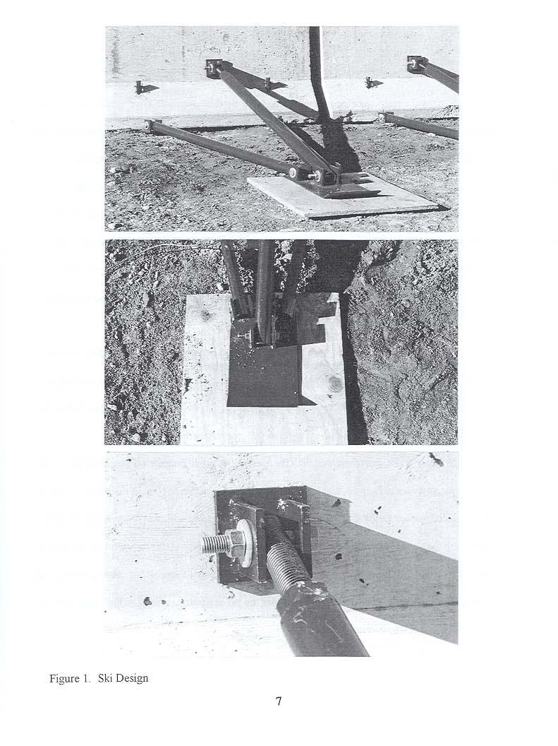
14 3 SKI DESIGN Various design concepts were investigated with the conclusion that the most promising alternative was an apparatus that would allow the barriers to slide laterally, as opposed to one that holds the barrier in its original place. The initial concept involved placing flat sheets at one or more location under each rail segment. Spacer blocks between the sheets and the barrier would allow the barrier to be installed in a vertical position on modest slopes. Unfortunately, this concept relies on the moment capacity of the sheeting to prevent the barrier from rotating or tipping during a severe impact. The required moment capacity to prevent this behavior was found to be unreasonably high and therefore the sheeting concept was rejected. In an effort to increase the moment capacity, a truss system was developed that would attach the barrier to a smaller piece of sheeting placed behind the barrier. In this design the ski plate was located approximately four feet from the barrier, as shown in Appendix A. The basic design called for two ski systems on each barrier segment. Based on preliminary estimates of the impact forces measured during impacts with safety shaped barriers (3) the maximum overturning moment during a crash test of a temporary barrier was estimated to be 4.5 kn-m (3.3 kip-ft). Each ski system was then designed to resist half of this moment. The truss system incorporated in the ski system utilizes a single compression member that carries the lateral load on top of the barrier down to the ground. Soil forces provide vertical support for the ski and two tensile members carry the lateral loads back to the base of the barrier segment, as shown in Figure 1. A 2 ft square piece of 3/4 in. plywood is placed under the ski to prevent it from gouging into the soil. This is attached by placing a 1/4 in wood screw through the ski and into the plywood. The wood screw is designed to restrain the plywood prior to impact and then shear off during an accident. The plywood
15 also elevates the ski so that soil erosion is not as likely to cause the ski to become embedded in the soil. The compression tube is designed to be adjustable so that the ski can be used on level ground or on a slope.
16
17 4 STATIC TESTING Two static tests were conducted to test the performance of the ski components when subjected to a high load. The tests were designed to evaluate the interaction between the barrier and the ski. The value of the test load was determined by the maximum capacity of the loading ram and pump, which was 15,000 lbs. This load correlates with a 19 kn-m (14.1 kip-ft) overturning moment compared to the design value of 39.7 kn-m (29.3 kip-ft). For static testing the ski plate was bolted to the concrete and additional anchor plates were set to keep the ski plate from moving, as shown in Figure 2. Two holes were drilled in the test barrier 1267 mm from each end in order to attach the ram to the barrier. This test set-up, along with all required attachment hardware are shown in Figure 3. The first test was assembled with the barrier located perpendicular to the loading ram and a load of 15,000 lbs was applied to the barrier, 7,500 lbs through each chain. The only yielding that took place occurred in the ski plates, as shown in Figure 2. This yielding was anticipated since the plates, which are only 1/4 in. thick, were fixed to the concrete apron for this test. The second test was assembled with the barrier located 30 degrees off perpendicular to the loading ram, as shown in Figure 3, and a load of 15,000 lbs was again applied to the barrier. The ski plates yielded similiar to the first static test. The barrier began to spall where the lower structural members of the ski are connected to the barrier. Concrete breakout at this location was not a great concern since longitudinal steel reinforcement is located between the steel attachment of the ski and the edge of the barrier. This testing showed that the ski apparatus upheld the high load and that barrier-ski damage was minimal.
18
19 Figure 3 Angled Load Static Test to
20 5 TEST CONDITIONS 5.1 Test Facility The Midwest Roadside Safety Facility's (MwRSF s) outdoor testing site is located at the Lincoln Air-Park on the northwest corner of the Lincoln Municipal Airport. The test facility is approximately 5-mi (8-km) northwest of the University of Nebraska-Lincoln. The site is surrounded and protected by an 8-ft (2.44-m) high chain-link security fence. 5.2 Vehicle Tow System A reverse cable tow system with a 1:2 mechanical advantage was used to propel the test vehicle. The distance traveled and the speed of the tow vehicle are one-half that of the test vehicle. The test vehicle was released from the tow cable before impact with the barrier system. A fifth wheel, built by the Nucleus Corporation, was located on the tow vehicle and used in conjunction with a digital speedometer to increase the accuracy of the test vehicle impact speed. 5.3 Vehicle Guidance System A vehicle guidance system developed by Hinch (8) was used to steer the test vehicle. A guide-flag, attached to the front-left wheel and the guide cable, was sheared off before impact. The 9.5-mm (3/8-in) diameter guide cable was tensioned to approximately 13.3-kN (3,000-lbs), and supported laterally and vertically every 30.5-m (100-ft) by hinged stanchions. The hinged stanchions stood upright while holding up the guide cable, but as the vehicle was towed down the line, the guide-flag struck and knocked each stanchion to the ground. The vehicle guidance system was approximately 460-m long. 1
21 5.4 Test Vehicle The test vehicle used for test KTS-1 was a 1990 Chevy 2500 Series 3/4-ton pickup truck. The test inertial and gross static weights were 1998-kg (4404-lbs). The test vehicle is shown in Figure 4, and its dimensions are shown in Figure 5. Black and white checkered targets were placed on the test vehicle for use in the high-speed film analysis, as shown in Figure 6. Two targets were located on the center of gravity, one on the top and one on the driver's side of the test vehicle. Additional targets, visible from external high-speed cameras, were placed on the vehicle for reference during film analysis. The front wheels of the test vehicle were aligned for camber, caster, and toe-in values of zero so that the vehicle would track properly along the guide cable. Two 5B flash bulbs were mounted on the hood of the vehicles to pinpoint the time of impact with the bridge railing on the high-speed film. The flash bulbs were fired by a pressure tape switch mounted on the front face of the bumper. A remotely controlled brake system was installed in the test vehicle so that it could be brought safely to a stop after the test. 5.5 Data Acquisition Systems High Speed Photography Five high-speed 16-mm cameras, with operating speeds of approximately 500 frames/sec, were used to film the crash test. A Red Lake Locam with a wide-angle 12.5-mm lens was placed above the test installation to provide a field of view perpendicular to the ground. A Red Lake Locam with a 76-mm lens was placed downstream of the impact point and had a field of view parallel to the barrier. A Red Lake Locam with a 12.5 to 75-mm zoom lens was placed on the traffic side of the barrier and had a field of view perpendicular to the barrier. A Red Lake Locam with a 12.5-mm lens was placed upstream and behind 1
22 the barrier. A Red Lake Locam with a 12.5 to 75-mm zoom lens was placed on the back side of the bridge rail and had a field of view perpendicular to the barrier Accelerometers Two triaxial piezoresistive accelerometer systems with a range of +200 G's was used to measure the acceleration in the longitudinal, lateral, and vertical directions. The environmental shock and vibration sensor/recorder system, Models EDR-3 and EDR-4, were developed by Instrumented Sensor Technology (IST) of Okemos, Michigan. The EDR-3 was configured with 256 Kb of RAM memory and a 1,120 Hz filter and was set to sample data at 3200 samples/sec. The EDR-4 is the next generation of the EDR-3, and was set to sample data at 10,000 samples/sec. Computer software, "DynaMax 1 (DM-1)" and "DADiSP" were used to digitize, analyze, and plot the accelerometer data Pressure Tape Switches Five pressure tape switches spaced at 2-m intervals were used to determine the speed of the vehicle before impact. Each tape switch fired a strobe light and sent an electronic timing mark to the data acquisition system as the front tire of the test vehicle passed over it. Test vehicle speeds were determined from recorded electronic timing mark data. Strobe lights and high-speed film analysis are used only as a backup in the event that vehicle speeds cannot be determined from the electronic data Strain Gages Ten weldable LWK-06-W250B-350 strain gages were installed on the skis upstream and downstream from impact to determine the loads in the members. Four were installed on the tension members and six were installed on the compression members, as shown in Figure 7. The nominal resistance of the gages was 350.0±1.4 ohms with a gauge factor equal to The 1
23 operating temperature limits of the gages was -195 to +260 degrees Celsius. The strain limits of the gages were 0.5% in tension or compression (5000:,). The strain gages were manufactured by the Micro- Measurements Division of Measurements Group, Inc. of Raleigh, North Carolina. The installation procedure required that the metal surface be clean and free from debris and oxidation. Once the surface had been prepared, the gauges were spot welded to the test surface. A Measurements Group Vishay Model 2310 signal conditioning amplifier was used to condition and amplify the low-level signals to high-level outputs for multichannel, simultaneous dynamic recording on "EGAA" software. After the signal was amplified it was sent to a ComputerScope ISC-16 data acquisition board before being sent to the computer software. The sample rate for all gages was 200 samples per second, and the duration of sampling was 10 seconds. 1

24
25
26 := tl. I f~ c 1 T~= k ~-h-~-- T EST #: _----'-'K'--'-T--=S~l' TARGET GEOMETRY (in) Q 30,25 b 26,75 c 108 d 77,75 e 72,75 f 72, ,5 h 57,5 i 75,5 j 40,50 k 27,375 44,75 Figure 6. Vehicle Target Locations, Test KTS-1 17
27
28 6 CRASH TEST RESULTS 6.1 Test KTS-1 A 62.0-m long barrier system was constructed on soil at the MwRSF outdoor test site, as shown in Figure 8. The barrier system consisted of 17 PCBs, each measuring 3,800 mm. The ski configuration discussed earlier was connected to the impact barrier, as well as three additional barriers upstream from impact, and six barriers downstream from impact. Design details for the joint connections and steel reinforcement are shown in Appendix B. It is noted that five additional barrier sections were connected to the upstream end of the installation to better represent an actual field installation. The 1,998-kg pickup truck impacted the concrete barrier 1.20 m upstream from the centerline of the gap between barrier nos. 8 and 9 at a speed of 99.6 km/h and at an angle of 26.9 degrees, as shown in Figure 9. A summary of the test results and the sequential photographs are shown in Figure 10. Additional sequential photographs are shown in Figure 11. Documentary photographs of the crash test are shown in Figures 12 and Test Description After impact, the right-front tire of the vehicle became airborne as it began to climb the face of the barrier, and the right-front corner of the vehicle was crushed inward. The right-front tire deflated as it contacted the gap between barrier nos. 8 and 9, and the right-front corner continued to crush inward and extend over the top of the barrier. As the right-front tire continued to climb the face of the barrier, the leftfront tire lost contact with the ground just before the vehicle contacted the gap between barrier nos. 9 and 10. The right-front tire continued to climb until it was on top of the rail and then the right-rear tire came into contact with barrier no. 9. The left-rear tire lost contact with the ground as the vehicle impacted the 1
29 gap between barrier nos. 10 and 11, so the entire vehicle was airborne, with the exception of the right-front tire which was still in contact with the top of the rail. The right-front tire then came off the top of the rail followed by the left-front tire returning to the ground. The other three tires returned to the ground, the rightfront, then the right-rear, and finally the left-rear. All four tires subsequently left the ground again as the vehicle recontacted the wall. The vehicle then came back down on all four tires and slid sideways until coming to a stop downstream of impact as shown in Figure Vehicle Damage Vehicle damage was acceptable, as shown in Figure 14. The right-front quarter panel was crushed in and the right door was deformed outward at the top. The right-front rim was bent in two different places and the tire was torn. There was no major undercarriage damage or disengagements and there was also no box contact. There was only a slight amount of occupant compartment damage with a small crease in the back portion of the passenger side. The deformations were judged to be insufficient to cause serious injury to the vehicle occupants. 6.4 Barrier and Ski Damage Barrier damage was minor, as shown in Figures 15 through 17. Concrete damage was mostly cosmetic, consisting of tire marks, scrapes, gouges, and minor spalling. Eleven steel pins were also deformed, with the damage ranging from slight to extensive. The maximum permanent set deflection of the barrier was 1.16 m. No damage was done to the skis with the exception of slight ski plate damage, as shown in Figure 18. 2
30 6.5 Occupant Risk Values The normalized occupant impact velocities in the longitudinal and lateral directions were determined to be 7.0 m/sec and 4.8 m/sec, respectively. The maximum 10 ms average occupant ridedown decelerations in the longitudinal and lateral directions were 3.5 g's and 10.7 g's, respectively. It is noted that the occupant impact velocities and occupant ridedown decelerations were within the suggested limits provided in NCHRP Report No. 350 (2). The results of the occupant risk, determined from accelerometer data, are summarized in Figure 10. Results are shown graphically in Appendix C. 6.6 Discussion The analysis of the test results for test KTS-1 showed that the barrier contained and redirected the vehicle with controlled lateral displacement of the barrier. The vehicle remained upright both during and after the collision and with significant vehicle yaw and pitch movements occurring during the impact. The maximum roll angle during this test was 18.1 degrees, which compares well with tests of other temporary barrier systems (1). Strain gage measurements showed a maximum load of 66,060 N, (14,850 lbs), in one of the compression members and a maximum load of 27,360 N, (6,150 lbs) in one of the tension members. These values correlate to an overturning moment of 32.6 kn-m (24.1 kip-ft) which is very close to the design loads. All strain gage data is summarized in Table 2. Based on the results of this test, it was determined that this system was acceptable according to the criteria presented in NCHRP Report 350 (2). 2

31

32

33

34

35

36
37
38
39
40
41
42 Table 2. Summary of Loads Obtained from Strain Gages Strain Gage No. Tension or Compression Maximum Force (lbs) 1 Tension Tension Tension Tension Compression Compression Compression Compression Compression Compression
43 7 SUMMARY AND CONCLUSIONS A concrete barrier system for off-road applications was developed and subjected to full-scale vehicle crash testing. The design of this system addressed concerns for safety, economy, structural integrity, constructability, ease of installation, and maintenance. One crash test was conducted according to Test Level 3 of NCHRP Report 350 (2). This test successfully passed the required criteria, although significant vehicle pitch and yaw motions were encountered during the test. The behavior witnessed, however, is typical of this type of test. Vehicle roll was minimal, however, which is unusual for this type of test. This concrete barrier system proved to be capable of preventing the concrete barriers from digging into the soil, a behavior which could cause the barrier sections to rotate considerably or even overturn. A summary of the safety performance evaluation is provided in Table 3. Based on the results of this research, it was determined that the performance of this system was acceptable according to the criteria presented for Test Level 3 of NCHRP Report 350 (2). 3
44 Table 3. Summary of Safety Performance Evaluation Results Evaluation Factors Evaluation Criteria Test KTS-1 Structural Adequacy Occupant Risk Vehicle Trajectory A. Test article should contain and redirect the vehicle; the vehicle should not penetrate, underride, or override the installation although controlled lateral deflection of the test article is acceptable. D. Detached elements, fragments or other debris from the test article should not penetrate or show potential for penetrating the occupant compartment, or present an undue hazard to other traffic, pedestrians, or personnel in a work zone. Deformations of, or intrusions into, the occupant compartment that could cause serious injuries should not be permitted. F. The vehicle should remain upright during and after collision although moderate roll, pitching and yawing are acceptable. K. After collision it is preferable that the vehicle's trajectory not intrude into adjacent traffic lanes. L. The occupant impact velocity in the longitudinal direction should not exceed 12 m/sec and the occupant ridedown acceleration in the longitudinal direction should not exceed 20 G's. M. The exit angle from the test article preferably should be less than 60 percent of test impact angle, measured at time of vehicle loss of contact with test device. S S S S S S S - (Satisfactory) M - (Marginal) U - (Unsatisfactory)
45 REFERENCES 1. Pfeifer, B.G., Holloway, J.C., Faller, R.K., Ataullah, S., Post, E.R., Full-Scale 4,500 lb. Vehicle Crash Test on the Permanent Precast Concrete Median Barrier, Transportation Research Report TRP , Midwest Roadside Safety Facility, University of Nebraska-Lincoln, Lincoln, Nebraska Ross, H.E., Sicking, D.L., Zimmer, R.A., and Michie, J.D., Recommended Procedures for the Safety Performance Evaluation of Highway Features, Cooperative Research Program (NCHRP) Report No. 350, Transportation Research Board, Washington, D.C., Bronstad, M.E., Calcote, L.R., and Kimball, C.E., Jr., Concrete Median Barrier Research - Vol. 2 Research Report, Report No. FHWA-RD-77-4, Submitted to the Offices of Research and Development, Federal Highway Administration, Performed by Southwest Research Institute, March Buth, C.E., Campise, W.L., Griffin III, L.I., Love, M.L., and Sicking, D.L., Performance Limits of Longitudinal Barrier Systems - Volume I: Summary Report, FHWA-RD , Final Report to the Federal Highway Administration, Office of Safety and Traffic Operations R&D, Performed by Texas Transportation Institute, Texas A&M University, May Fortuniewicz, J.S., Bryden, J.E., and Phillips, R.G., Crash Tests of Portable Concrete Median Barrier for Maintenance Zones, Report No. FHWA/NY/RR-82/102, Final Report to the Office of Research, Development, and Technology, Federal Highway Administration, Performed by the Engineering Research and Development Bureau, New York State Department of Transportation, December Mak, K.K., and Sicking, D.L., Rollover Caused by Concrete Safety Shape Barrier - Volume I: Technical Report and Volume II: Appendices, Report Nos. FHWA-RD-88219/220, Performed for the Office of Safety and Traffic Operations R&D, Federal Highway Administration, Performed by the Texas Transportation Institute, Texas A&M University, January Buth, C.E., Hirsch, T.J., and McDevitt, C.F., Performance Level 2 Bridge Railings, Transportation Research Record No. 1258, Transportation Research Board, National Research Council, Washington D.C., Hinch, J., Yang, T-L, and Owings, R., Guidance Systems for Vehicle Testing, ENSCO, Inc., Springfield, VA, Vehicle Damage Scale for Traffic Investigators, Second Edition, Technical Bulletin No. 1, 3
46 Traffic Accident Data (TAD) Project, National Safety Council, Chicago, Illinois, Collision Deformation Classification - Recommended Practice J224 March 1980, Handbook Volume 4, Society of Automotive Engineers (SAE), Warrendale, Pennsylvania, Faller, R.K., Rohde, J.R., Rosson, B.T., Smith, R. P., Addink, K.A., Development of a TL-3 F-Shape Temporary Concrete Median Barrier, Research Report TRP , Midwest Roadside Safety Facility, University of Nebraska-Lincoln, Lincoln, Nebraska
47 9 APPENDICES APPENDIX A - SKI SYSTEM DESIGN DRAWINGS Figure A-1. Component Details Figure A-2. Component Details (cont) Figure A-3. Component Details (cont) Figure A-4. Component Details (cont) Figure A-5. Welding Details Figure A-6. Ski Connection to Barrier
48
49
50 ,4'1 113/8' r I- r pi I 4' L 3' 1 - ~' ~I I Part #7: 1 each Part #9: 2 each +>-,- 8' ~, ~. ~I -, 1/4' I l ""=(1)112' 50'~ ~.I' Grind Off >-' 11' I E][.I 3/8' t 62J Grind Off for AsseMbly ~ Part #8: 1 each Part #10: 2 each - - Figure A-3. Component Details (cont).~ MwR S F University oj Nebraska V C.E. Department SKI DATE: I COMPOnent Deto.lls SCALE: none I I DR'N: EAK Sheet 3 of 4 I report03
51 0 ' I \ I I \ / "- I \ I. \ 1 I \ I, / ",/..._-"" 7/8" Parts #11 8x 12: Threaded ready rod and nut, 1 set --I- t=:2'=:j 1 3/S' ) "'- =====-=t co:ter Pin Holes 1rl ChuMfer Ends Slightly to Euse Instullu tion 1/8/1 diu, ~ 1 5/8/1 '-- Part #14: 2 each Part #13: 1 each.mwrsf SKI University of Nebraska C.E. Department DATE: COMQOnent Deto.lls SCALE: none L -' DR'N: EAK I Sheet 4 of 4 I reparto4 Figure A-4. Component Details (cont)
52
53
54 APPENDIX B - BARRIER SYSTEM A concrete median barrier was developed and subjected to full scale crash testing by MwRSF in 1996 for the Midwest State's Regional Pooled Fund Program (11). The concrete median barrier developed, shown in Figures B-1 and B-2, was first tested with unsatisfactory results. The barrier did not adequately contain and redirect the vehicle, so the concrete barrier connections were modified as shown in Figure B-3. A retest was performed on the modified barrier system and the results were acceptable according to the TL-3 crash test conditions of NCHRP Report No. 350 (2). This modified barrier system was used for the off-road application test described in this report, as shown in Figures B-4 and B-5. Following the successful completion of this testing, it is recommended that the barrier details shown in Figures B-6 and B-7 be used for future construction. 4
55
56 I rt L 50 rr- 5O, 200i..-+I---.so OO -of , of----- eoo,-----i--200 I I I I I I I I I r-..j ~ r-.-.oii DtO L... J th -l i:i V- (.l... I ) TYP. low smtiiup (2)... \ ~ 20W LOOP WI I V 32mrnll (2) lI0...., m + f m I I I I I I I... LOOP"',.~ SOmm." y :-~::--. sis III r III I III -III III ISO I.so.so I ISO ~-~~ ==1--+_ _+~ =1~--_J HOTES: 11 All dlm'natont a,.. In Mm. 2 Wlnlmum COY" of 40 Mm. 3 All r.lnfor'cmm.nt I. Grad... Po ASN AItSU. Wlnlmum lap of all longitudinal bare I. 500 Mm. 1,1 III L INTERIOR STIRRUP END STIRRUP (first 2 each end) Figure B-2. Original Barrier Reinforcement Details
57
58 ~1' ~'1 ~ 190..L - 0 =:1-50 l= ~~~ 190 -L Side View f~~ I _. r 50 ~-rl J 5 I End View 1 r approx. 80 mm 0 0 See Detat! " ff Connection Detail ('+-,,---...,.,.---< E60 I' 623 I c=:j1 ~I 15mm~J~ I- Rod 32mm (A36) f-122-l ~~J5 35mm ~-rl-- centered on plate Top & Bottom Plate (A36) Detail "8" H (!J) 13mm Bolt & Nut (Grade 8) Isometric Figure B-4. Barrier Design for KTS-I
59
60 ~1' BOO~ ~'1 ~ 190..L - :=:J , t 190..L BOO y,!, 150 I End View.-kh;::m==m=-r--<E60-1 r opprox. 80mm ,J See Detail C' Connection Detail <: e+-,6::::m":::m...---<e60 I 623 'I r==71 ~ I 15mm I- Rod 32mm I/J (A36) ~ reil ~J5 35mm~-I'icentered on plate Top & Bottom Plate (A36) Detail "c" H IlJl 13mm I/J Bolt & Nut (Grade 8) Isometeric Figure B-6. Barrier Design for Future Construction
61
62 APPENDIX C - ACCELEROMETER DATA ANALYSIS Figure C-1. Graph of Longitudinal Deceleration Figure C-2. Graph of Longitudinal Occupant Impact Velocity Figure C-3. Graph of Longitudinal Occupant Displacement Figure C-4. Graph of Lateral Deceleration Figure C-5. Graph of Lateral Occupant Impact Velocity Figure C-6. Graph of Lateral Occupant Displacement 5
63 Longitudinal Deceleration - Test KTS-l ;! 1 1 )---- ~ ! _..._... ft r n u _...,.< ~ " '-._ O.ts 0.10 us Figure C-l. Graph of Longitudinal Deceleration, Test KTS-l 54
64 ,. 2 / V / Relative. Long. Occup. Velocity - Test KTS-l ~.. - V ~ If ~ ~ V ' ' G Sec Figure C-2. Graph of Longitudinal Occupant Impact Velocity, Test KTS-I 55
65 Relative Longitudinal Occ. Disp. - Test KTS-l 1." ~v / V / V /" V.. " - L ~.u " % 0.14 Sec Figure C-3. Graph of Longitudinal Occupant Displacement, Test KTS-I 56
66 Lateral Deceleration - Test KTS-l [\ i/-. r \ ~ ~... /"-.... '" /'-.~ ~ ~ 1 V!) V \..~ Soc Figure C-4. Graph of Lateral Deceleration, Test KTS-l 57
67 Lateral Occupant Velocity - Test KTS-l H----r- "i. vi -br _ i / _..._-+.._..._ f _ ; - 1 j'., $ OAO Sec Figure C-5. Graph of Lateral Occupant Impact Velocity, Test KTS-l 58
68 Lateral Occupant Displacement - Test KTS-l I.,"' : V V.-/ V ~ V V V V V I % " % Sec Figure C-6. Graph of Lateral Occupant Displacement, Test KTS-l 59
DEFLECTION LIMITS FOR TEMPORARY CONCRETE BARRIERS
 Midwest State s Regional Pooled Fund Research Program Fiscal Year 1998-1999 (Year 9) NDOR Research Project Number SPR-3(017) DEFLECTION LIMITS FOR TEMPORARY CONCRETE BARRIERS Submitted by Dean L. Sicking,
PERFORMANCE EVALUATION OF THE PERMANENT NEW JERSEY SAFETY SHAPE BARRIER UPDATE TO NCHRP 350 TEST NO (2214NJ-2)
") PERFORMANCE EVALUATION OF THE PERMANENT NEW JERSEY SAFETY SHAPE BARRIER UPDATE TO NCHRP 350 TEST NO. 4-12 (2214NJ-2) Submitted by Karla A. Polivka, M.S.M.E., E.I.T. Research Associate Engineer Dean L.
PERFORMANCE EVALUATION OF THE PERMANENT NEW JERSEY SAFETY SHAPE BARRIER UPDATE TO NCHRP 350 TEST NO. 4-12 (2214NJ-2) Submitted by Karla A. Polivka, M.S.M.E., E.I.T. Research Associate Engineer Dean L.
PERFORMANCE EVALUATION OF THE FREE-STANDING TEMPORARY BARRIER UPDATE TO NCHRP 350 TEST NO WITH 28" C.G. HEIGHT (2214TB-2)
") PERFORMANCE EVALUATION OF THE FREE-STANDING TEMPORARY BARRIER UPDATE TO NCHRP 350 TEST NO. 3-11 WITH 28" C.G. HEIGHT (2214TB-2) Submitted by Karla A. Polivka, M.S.M.E., E.I.T. Research Associate Engineer
PERFORMANCE EVALUATION OF THE FREE-STANDING TEMPORARY BARRIER UPDATE TO NCHRP 350 TEST NO. 3-11 WITH 28" C.G. HEIGHT (2214TB-2) Submitted by Karla A. Polivka, M.S.M.E., E.I.T. Research Associate Engineer
PERFORMANCE EVALUATION OF THE FREE-STANDING TEMPORARY BARRIER UPDATE TO NCHRP 350 TEST NO (2214TB-1)
") PERFORMANCE EVALUATION OF THE FREE-STANDING TEMPORARY BARRIER UPDATE TO NCHRP 350 TEST NO. 3-11 (2214TB-1) Submitted by Karla A. Polivka, M.S.M.E., E.I.T. Research Associate Engineer Dean L. Sicking, Ph.D.,
PERFORMANCE EVALUATION OF THE FREE-STANDING TEMPORARY BARRIER UPDATE TO NCHRP 350 TEST NO. 3-11 (2214TB-1) Submitted by Karla A. Polivka, M.S.M.E., E.I.T. Research Associate Engineer Dean L. Sicking, Ph.D.,
PERFORMANCE EVALUATION OF THE MODIFIED G4(1S) GUARDRAIL UPDATE TO NCHRP 350 TEST NO WITH 28" C.G. HEIGHT (2214WB-2)
 GUARDRAIL UPDATE TO NCHRP 350 TEST NO WITH 28 C.G. HEIGHT (2214WB-2)") PERFORMANCE EVALUATION OF THE MODIFIED G4(1S) GUARDRAIL UPDATE TO NCHRP 350 TEST NO. 3-11 WITH 28" C.G. HEIGHT (2214WB-2) Submitted by Karla A. Polivka, M.S.M.E., E.I.T. Research Associate Engineer Dean
PERFORMANCE EVALUATION OF THE MODIFIED G4(1S) GUARDRAIL UPDATE TO NCHRP 350 TEST NO. 3-11 WITH 28" C.G. HEIGHT (2214WB-2) Submitted by Karla A. Polivka, M.S.M.E., E.I.T. Research Associate Engineer Dean
Form DOT F (8-72) Texas Transportation Institute The Texas A&M University System College Station, Texas
 Texas Transportation Institute The Texas A&M University System College Station, Texas") 1. Report No. FHWA/TX-02/4162-1 Technical Report Documentation Page 2. Government Accession No. 3. Recipient's Catalog No. 4. Title and Subtitle EVALUATION OF TEXAS GRID-SLOT PORTABLE CONCRETE BARRIER
1. Report No. FHWA/TX-02/4162-1 Technical Report Documentation Page 2. Government Accession No. 3. Recipient's Catalog No. 4. Title and Subtitle EVALUATION OF TEXAS GRID-SLOT PORTABLE CONCRETE BARRIER
NCHRP Report 350 Test 4-12 of the Modified Thrie Beam Guardrail
 NCHRP Report 350 Test 4-12 of the Modified Thrie Beam Guardrail PUBLICATION NO. FHWA-RD-99-065 DECEMBER 1999 Research, Development, and Technology Turner-Fairbank Highway Research Center 6300 Georgetown
A MASH Compliant W-Beam Median Guardrail System
 0 0 0 0 0 A MASH Compliant W-Beam Median Guardrail System By A. Y. Abu-Odeh, R. P. Bligh, W. Odell, A. Meza, and W. L. Menges Submitted: July 0, 0 Word Count:, + ( figures + tables=,000) =, words Authors:
Midwest Guardrail System Without Blockouts
 Duplication for publication or sale is strictly prohibited without prior written permission of the Transportation Research Board Paper No. 13-0418 Midwest Guardrail System Without Blockouts by John D.
Evaluation of the Midwest Guardrail System Stiffness Transition with Curb
 Duplication for publication or sale is strictly prohibited without prior written permission of the Transportation Research Board Paper No. -0 Evaluation of the Midwest Guardrail System Stiffness Transition
PR V2. Submitted by. Professor MIDWEST Vine Street (402) Submitted to
 Submitted to") FINAL REPORT PR4893118-V2 ZONE OF INTRUSION STUDY Submitted by John D. Reid, Ph.D. Professor Dean L.. Sicking, Ph.D., P.E. Professorr and MwRSF Director MIDWEST ROADSIDE SAFETY FACILITY University of Nebraska-Lincoln
FINAL REPORT PR4893118-V2 ZONE OF INTRUSION STUDY Submitted by John D. Reid, Ph.D. Professor Dean L.. Sicking, Ph.D., P.E. Professorr and MwRSF Director MIDWEST ROADSIDE SAFETY FACILITY University of Nebraska-Lincoln
CRITICAL FLARE RATES FOR W-BEAM GUARDRAIL DETERMINING MAXIMUM CAPACITY USING COMPUTER SIMULATION NCHRP 17-20(3)
") CRITICAL FLARE RATES FOR W-BEAM GUARDRAIL DETERMINING MAXIMUM CAPACITY USING COMPUTER SIMULATION NCHRP 17-2(3) Submitted by Beau D. Kuipers, B.S.M.E., E.I.T. Graduate Research Assistant Ronald K. Faller,
CRITICAL FLARE RATES FOR W-BEAM GUARDRAIL DETERMINING MAXIMUM CAPACITY USING COMPUTER SIMULATION NCHRP 17-2(3) Submitted by Beau D. Kuipers, B.S.M.E., E.I.T. Graduate Research Assistant Ronald K. Faller,
VULCAN BARRIER TL-3 GENERAL SPECIFICATIONS
 VULCAN BARRIER TL-3 GENERAL SPECIFICATIONS I. GENERAL A. The VULCAN BARRIER TL-3 (VULCAN TL-3) shall be a highly portable and crashworthy longitudinal barrier especially suited for use as a temporary barrier
VULCAN BARRIER TL-3 GENERAL SPECIFICATIONS
 VULCAN BARRIER TL-3 GENERAL SPECIFICATIONS I. GENERAL A. The VULCAN BARRIER TL-3 (VULCAN TL-3) shall be a highly portable and crashworthy longitudinal barrier especially suited for use as a temporary barrier
Evaluation and Design of ODOT s Type 5 Guardrail with Tubular Backup
 Evaluation and Design of ODOT s Type 5 Guardrail with Tubular Backup Draft Final Report Chuck A. Plaxico, Ph.D. James C. Kennedy, Jr., Ph.D. Charles R. Miele, P.E. for the Ohio Department of Transportation
Texas Transportation Institute The Texas A&M University System College Station, Texas
 1. Report No. FHWA/TX-05/9-8132-P7 4. Title and Subtitle TL-4 CRASH TESTING OF THE F411 BRIDGE RAIL 2. Government Accession No. 3. Recipient's Catalog No. 5. Report Date October 2004 Technical Report Documentation
VERIFICATION & VALIDATION REPORT of MGS Barrier Impact with 1100C Vehicle Using Toyota Yaris Coarse FE Model
 VERIFICATION & VALIDATION REPORT of MGS Barrier Impact with 1100C Vehicle Using Toyota Yaris Coarse FE Model CCSA VALIDATION/VERIFICATION REPORT Page 1 of 4 Project: CCSA Longitudinal Barriers on Curved,
Product Specification. ABSORB 350 TM TL-2 Non-Redirective, Gating, Crash Cushion Applied to Quickchange Moveable Barrier
 TB 000612 Rev. 0 Page 1 of 9 Product Specification ABSORB 350 TM TL-2 Non-Redirective, Gating, Crash Cushion Applied to Quickchange Moveable Barrier I. General The ABSORB 350 TM TL-2 System is a Non-Redirective,
CRASH TEST OF MILE POST MARKER. T. J. Hirsch Research Engineer. and. Eugene Buth Assistant Research Engineer. Research Report Number 146-8
 CRASH TEST OF MILE POST MARKER by T. J. Hirsch Research Engineer and Eugene Buth Assistant Research Engineer Research Report Number 146-8 Studies of Field Adaption of Impact Attenuation Systems Research
Texas Transportation Institute The Texas A&M University System College Station, Texas
 1. Report No. FHWA/TX-07/0-5527-1 4. Title and Subtitle DEVELOPMENT OF A LOW-PROFILE TO F-SHAPE TRANSITION BARRIER SEGMENT 2. Government Accession No. 3. Recipient's Catalog No. Technical Report Documentation
W-Beam Guiderail Transition from Light to Heavy Posts
 TRANSPORTATION RESEARCH RECORD 1198 55 W-Beam Guiderail Transition from Light to Heavy Posts DONALD G. HERRING AND JAMES E. BRYDEN Two full-scale crash tests evaluated a transition between lightand heavy-post
DEVELOPMENT OF A MASH TL-3 TRANSITION BETWEEN GUARDRAIL AND PORTABLE CONCRETE BARRIERS
 Duplication for publication or sale is strictly prohibited without prior written permission of the Transportation Research Board Paper No. 17-01712 DEVELOPMENT OF A MASH TL-3 TRANSITION BETWEEN GUARDRAIL
Evaluation of the Midwest Guardrail System stiffness transition with curb
 University of Nebraska - Lincoln DigitalCommons@University of Nebraska - Lincoln Civil Engineering Faculty Publications Civil Engineering 2016 Evaluation of the Midwest Guardrail System stiffness transition
February 8, In Reply Refer To: HSSD/CC-104
 February 8, 2008 200 New Jersey Avenue, SE. Washington, DC 20590 In Reply Refer To: HSSD/CC-04 Barry D. Stephens, P.E. Sr. Vice President Engineering Energy Absorption Systems, Inc. 367 Cincinnati Avenue
NCHRP Report 350 Crash Testing and Evaluation of the S-Square Mailbox System
 TTI: 0-5210 NCHRP Report 350 Crash Testing and Evaluation of the S-Square Mailbox System ISO 17025 Laboratory Testing Certificate # 2821.01 Crash testing performed at: TTI Proving Ground 3100 SH 47, Building
Manual for Assessing Safety Hardware
 American Association of State Highway and Transportation Officials Manual for Assessing Safety Hardware 2009 vii PREFACE Effective traffic barrier systems, end treatments, crash cushions, breakaway devices,
Development of a TL-5 Vertical Faced Concrete Median Barrier Incorporating Head Ejection Criteria
 Midwest States Regional Pooled Fund Research Program Fiscal Year 2004-2005 (Year 15) Research Project Number SPR-3(017) NDOR Sponsoring Agency Code RPFP-05-01 Development of a TL-5 Vertical Faced Median
BarrierGate. General Specifications. Manual Operations General Specifications
 BarrierGate General Specifications Manual Operations General Specifications BarrierGate GENERAL SPECIFICATIONS I. GENERAL A. The BarrierGate system (the gate) shall be designed and manufactured by Energy
Texas Transportation Institute The Texas A&M University System College Station, Texas
 1. Report No. FHWA/TX-04/9-8132-1 4. Title and Subtitle TESTING AND EVALUATION OF THE FLORIDA JERSEY SAFETY SHAPED BRIDGE RAIL 2. Government Accession No. 3. Recipient's Catalog No. 5. Report Date February
Technical Report Documentation Page Form DOT F (8-72) Reproduction of completed page authorized
 Reproduction of completed page authorized") 1. Report No. FHWA/TX-05/0-4162-3 4. Title and Subtitle 2. Government Accession No. 3. Recipient's Catalog No. DEVELOPMENT OF LOW-DEFLECTION PRECAST CONCRETE ARRIER 5. Report Date January 2005 Technical
1. Report No. FHWA/TX-05/0-4162-3 4. Title and Subtitle 2. Government Accession No. 3. Recipient's Catalog No. DEVELOPMENT OF LOW-DEFLECTION PRECAST CONCRETE ARRIER 5. Report Date January 2005 Technical
MASH08 TEST 3-11 OF THE ROCKINGHAM PRECAST CONCRETE BARRIER
 Proving Ground Report No. 400001-RPC4 Report Date: July 2009 MASH08 TEST 3-11 OF THE ROCKINGHAM PRECAST CONCRETE BARRIER by C. Eugene Buth, P.E. Research Engineer William F. Williams, P.E. Assistant Research
DEVELOPMENT OF A TRANSITION BETWEEN FREE-STANDING AND REDUCED-DEFLECTION PORTABLE CONCRETE BARRIERS PHASE I
 Research Project Number TPF-5(193) Supplement #78 DEVELOPMENT OF A TRANSITION BETWEEN FREE-STANDING AND REDUCED-DEFLECTION PORTABLE CONCRETE BARRIERS PHASE I Submitted by Mojdeh Asadollahi Pajouh, Ph.D.
MINIMUM EFFECTIVE LENGTH FOR THE MIDWEST GUARDRAIL SYSTEM
 Duplication for publication or sale is strictly prohibited without prior written permission of the Transportation Research Board Paper No. 15-0484 MINIMUM EFFECTIVE LENGTH FOR THE MIDWEST GUARDRAIL SYSTEM
MASH Test 3-11 on the T131RC Bridge Rail
 TTI: 9-1002-12 MASH Test 3-11 on the T131RC Bridge Rail ISO 17025 Laboratory Testing Certificate # 2821.01 Crash testing performed at: TTI Proving Ground 3100 SH 47, Building 7091 Bryan, TX 77807 Test
CRASH TESTING AND EVALUATION OF WORK ZONE TRAFFIC CONTROL DEVICES
 Paper No. 980627 CRASH TESTING AND EVALUATION OF WORK ZONE TRAFFIC CONTROL DEVICES by King K. Mak Phone: 210-698-2068 Fax: 210-698-2068 e-mail: king@tti3a.tamu.edu Texas Transportation Institute The Texas
Development of Combination Pedestrian-Traffic Bridge Railings
 TRANSPORTATION RESEARCH RECORD 1468 41 Development of Combination Pedestrian-Traffic Bridge Railings D. LANCE BULLARD, JR., WANDA L. MENGES, AND C. EUGENE BUTH Two bridge railing designs have been developed
Development and Implementation of the Simplified MGS Stiffness Transition
 Duplication for publication or sale is strictly prohibited without prior written permission of the Transportation Research Board Paper No. 12-3367 Development and Implementation of the Simplified MGS Stiffness
STI Project: Barrier Systems, Inc. RTS-QMB Longitudinal Barrier. Page 38 of 40 QBOR1. Appendix F (Continued) Figure F-3
 Figure F-3") Barrier Systems, Inc. RTS-QMB Longitudinal Barrier STI Project: QBOR1 Page 38 of 40 Appendix F (Continued) Figure F-3 t=.500sec 115 meters overall 37.1 Impact Severity (kj).. 141.6 Angle (deg).. 25 Speed
Barrier Systems, Inc. RTS-QMB Longitudinal Barrier STI Project: QBOR1 Page 38 of 40 Appendix F (Continued) Figure F-3 t=.500sec 115 meters overall 37.1 Impact Severity (kj).. 141.6 Angle (deg).. 25 Speed
Advances in Simulating Corrugated Beam Barriers under Vehicular Impact
 13 th International LS-DYNA Users Conference Session: Automotive Advances in Simulating Corrugated Beam Barriers under Vehicular Impact Akram Abu-Odeh Texas A&M Transportation Institute Abstract W-beam
July 10, Refer to: HSA-10/CC-78A
 July 10, 2003 Refer to: HSA-10/CC-78A Barry D. Stephens, P.E. Senior Vice President of Engineering ENERGY ABSORPTION Systems, Inc. 3617 Cincinnati Avenue Rocklin, California 95765 Dear Mr. Stephens: Your
Universal TAU-IIR Redirective, Non-Gating, Crash Cushion
 TB 110927 Rev. 0 Page 1 of 5 Product Specification Universal TAU-IIR Redirective, Non-Gating, Crash Cushion I. General The Universal TAU-IIR system is a Redirective, Non-Gating Crash Cushion in accordance
MASH TEST 3-11 OF THE TxDOT T222 BRIDGE RAIL
 TTI: 9-1002-12 MASH TEST 3-11 OF THE TxDOT T222 BRIDGE RAIL ISO 17025 Laboratory Testing Certificate # 2821.01 Crash testing performed at: TTI Proving Ground 3100 SH 47, Building 7091 Bryan, TX 77807 Test
SUMMARY CHANGES FOR NCHRP REPORT 350 GUIDELINES [NCHRP (02)] Keith A. Cota, Chairman Technical Committee on Roadside Safety June 14, 2007
![SUMMARY CHANGES FOR NCHRP REPORT 350 GUIDELINES [NCHRP (02)] Keith A. Cota, Chairman Technical Committee on Roadside Safety June 14, 2007](/thumbs/87/97351925.jpg "SUMMARY CHANGES FOR NCHRP REPORT 350 GUIDELINES [NCHRP (02)] Keith A. Cota, Chairman Technical Committee on Roadside Safety June 14, 2007") SUMMARY CHANGES FOR NCHRP REPORT 350 GUIDELINES [NCHRP 22-14 (02)] Keith A. Cota, Chairman Technical Committee on Roadside Safety June 14, 2007 BACKGROUND Circular 482 (1962) First full scale crash test
SUMMARY CHANGES FOR NCHRP REPORT 350 GUIDELINES [NCHRP 22-14 (02)] Keith A. Cota, Chairman Technical Committee on Roadside Safety June 14, 2007 BACKGROUND Circular 482 (1962) First full scale crash test
June 5, In Reply Refer To: HSSD/B-178. Mr. Kevin K. Groeneweg Mobile Barriers LLC Genesee Trail Road Golden, CO Dear Mr.
 June 5, 2008 1200 New Jersey Avenue, SE. Washington, DC 20590 In Reply Refer To: HSSD/B-178 Mr. Kevin K. Groeneweg Mobile Barriers LLC 24918 Genesee Trail Road Golden, CO 80401 Dear Mr. Groeneweg: This
Texas Transportation Institute The Texas A&M University System College Station, Texas
 2. Government Accession No. 3. Recipient's Catalog No. 1. Report No. FHWA/TX-03/0-4138-3 4. Title and Subtitle PERFORMANCE OF THE TXDOT T202 (MOD) BRIDGE RAIL REINFORCED WITH FIBER REINFORCED POLYMER BARS
Slotted Rail Guardrail Terminal
 TRANSPORTATION RESEARCH RECORD 1500 43 Slotted Rail Guardrail Terminal KING K. MAK, ROGER P. BLIGH, HAYES E. Ross, JR., AND DEAN L. SICKING A slotted rail terminal (SRT) for W-beam guardrails was successfully
GUARDRAIL TESTING MODIFIED ECCENTRIC LOADER TERMINAL (MELT) AT NCHRP 350 TL-2. Dean C. Alberson, Wanda L. Menges, and Rebecca R.
 AT NCHRP 350 TL-2. Dean C. Alberson, Wanda L. Menges, and Rebecca R.") GUARDRAIL TESTING MODIFIED ECCENTRIC LOADER TERMINAL (MELT) AT NCHRP 350 TL-2 Dean C. Alberson, Wanda L. Menges, and Rebecca R. Haug Prepared for The New England Transportation Consortium July 2002 NETCR
GUARDRAIL TESTING MODIFIED ECCENTRIC LOADER TERMINAL (MELT) AT NCHRP 350 TL-2 Dean C. Alberson, Wanda L. Menges, and Rebecca R. Haug Prepared for The New England Transportation Consortium July 2002 NETCR
AASHTO Manual for Assessing Safety Hardware, AASHTO/FHWA Joint Implementation Plan Standing Committee on Highways September 24, 2015
 AASHTO Manual for Assessing Safety Hardware, 2015 AASHTO/FHWA Joint Implementation Plan Standing Committee on Highways September 24, 2015 Full Scale MASH Crash Tests (NCHRP 22-14(02)) Conducted several
REPORT NUMBER: 301-CAL SAFETY COMPLIANCE TESTING FOR FMVSS 301 FUEL SYSTEM INTEGRITY HONDA MOTOR COMPANY 2007 HONDA ACCORD 4-DOOR SEDAN
 REPORT NUMBER: 301-CAL-07-05 SAFETY COMPLIANCE TESTING FOR FMVSS 301 FUEL SYSTEM INTEGRITY HONDA MOTOR COMPANY 2007 HONDA ACCORD 4-DOOR SEDAN NHTSA NUMBER: C75304 CALSPAN TEST NUMBER: 8832-F301-05 CALSPAN
W-Beam Approach Treatment at Bridge Rail Ends Near Intersecting Roadways
 TRANSPORTATION RESEARCH RECORD 1133 51 W-Beam Approach Treatment at Bridge Rail Ends Near Intersecting Roadways M. E. BRONSTAD, M. H. RAY, J. B. MAYER, JR., AND c. F. MCDEVITT This paper is concerned with
MASH TEST 3-10 ON 31-INCH W-BEAM GUARDRAIL WITH STANDARD OFFSET BLOCKS
 TTI: 9-1002 MASH TEST 3-10 ON 31-INCH W-BEAM GUARDRAIL WITH STANDARD OFFSET BLOCKS ISO 17025 Laboratory Testing Certificate # 2821.01 Crash testing performed at: TTI Proving Ground 3100 SH 47, Building
NCHRP Report 350 Evaluation of the Nebraska Thrie-Beam Transition
 NCHRP Report 350 Evaluation of the Nebraska Thrie-Beam Transition SPR-PL-l(34) P500 Brian O. Pfeifer, Ph.D., P.E. Research Associate Engineer Ronald K. Faller, Ph.D., P.E. Research Associate Engineer John
CRASH TEST AND EVALUATION OF 3-FT MOUNTING HEIGHT SIGN SUPPORT SYSTEM
 TTI: 9-1002-15 CRASH TEST AND EVALUATION OF 3-FT MOUNTING HEIGHT SIGN SUPPORT SYSTEM ISO 17025 Laboratory Testing Certificate # 2821.01 Crash testing performed at: TTI Proving Ground 3100 SH 47, Building
Development and Validation of a Finite Element Model of an Energy-absorbing Guardrail End Terminal
 Development and Validation of a Finite Element Model of an Energy-absorbing Guardrail End Terminal Yunzhu Meng 1, Costin Untaroiu 1 1 Department of Biomedical Engineering and Virginia Tech, Blacksburg,
CRASH TESTING OF RSA/K&C ANTI-RAM FOUNDATION BOLLARD PAD IN ACCORDANCE WITH U.S. DEPARTMENT OF STATE DIPLOMATIC SECURITY SD-STD-02.
 CRASH TESTING OF RSA/K&C ANTI-RAM FOUNDATION BOLLARD PAD IN ACCORDANCE WITH U.S. DEPARTMENT OF STATE DIPLOMATIC SECURITY SD-STD-02.01 REVISION A Prepared for RSA Protective Technologies, LLC FINAL REPORT
SAFETY PERFORMANCE OF WORK-ZONE DEVICES UNDER MASH TESTING
 SAFETY PERFORMANCE OF WORK-ZONE DEVICES UNDER MASH TESTING Schmidt, Faller, Lechtenberg, Sicking, Holloway Midwest Roadside Safety Facility Nebraska Transportation Center University of Nebraska-Lincoln
TEXAS TRANSPORTATION INSTITUTE THE TEXAS A & M UNIVERSITY SYSTEM COLLEGE STATION, TEXAS 77843
 NCHRP REPORT 350 TEST 3-11 OF THE NEW YORK DOT PORTABLE CONCRETE BARRIER WITH I-BEAM CONNECTION (RETEST) by Roger P. Bligh, P.E. Assistant Research Engineer Wanda L. Menges Associate Research Specialist
Assessing Options for Improving Roadside Barrier Crashworthiness
 13 th International LS-DYNA Users Conference Session: Simulation Assessing Options for Improving Roadside Barrier Crashworthiness D. Marzougui, C.D. Kan, and K.S. Opiela Center for Collision Safety and
Sponsored by Roadside Safety Research Program Pooled Fund Study No. TPF-5(114)
") Proving Ground Test Report No. 405160-23-2 Test Report Date: February 2012 MASH TEST 3-11 OF THE W-BEAM GUARDRAIL ON LOW-FILL BOX CULVERT by William F. Williams, P.E. Associate Research Engineer and Wanda
Proving Ground Test Report No. 405160-23-2 Test Report Date: February 2012 MASH TEST 3-11 OF THE W-BEAM GUARDRAIL ON LOW-FILL BOX CULVERT by William F. Williams, P.E. Associate Research Engineer and Wanda
Update to NCHRP Report 350. Current Safety Issues
 Workshop on the Update to NCHRP Report 350 and Current Safety Issues July 18 21, 2004 Sponsored by TRB COMMITTEE AFB20 ROADSIDE SAFETY DESIGN DoubleTree Hotel Overland Park-Corporate Woods 10100 College
Continued Development of a Non-Proprietary, High-Tension, Cable End Terminal System
 University of Nebraska - Lincoln DigitalCommons@University of Nebraska - Lincoln Nebraska Department of Transportation Research Reports Nebraska LTAP 4-29-2016 Continued Development of a Non-Proprietary,
s MEDIAN BARRIERS FOR TEXAS HIGHWAYS
 s MEDIAN BARRIERS FOR TEXAS HIGHWAYS SUMMARY REPORT of Research Report Number 146-4 Study 2-8-68-146 Cooperative Research Program of the Texas Transportation Institute and the Texas Highway Department
MASH TEST 3-11 OF THE TxDOT SINGLE SLOPE BRIDGE RAIL (TYPE SSTR) ON PAN-FORMED BRIDGE DECK
 ON PAN-FORMED BRIDGE DECK") TTI: 9-1002 MASH TEST 3-11 OF THE TxDOT SINGLE SLOPE BRIDGE RAIL (TYPE SSTR) ON PAN-FORMED BRIDGE DECK ISO 17025 Laboratory Testing Certificate # 2821.01 Crash testing performed at: TTI Proving Ground
TTI: 9-1002 MASH TEST 3-11 OF THE TxDOT SINGLE SLOPE BRIDGE RAIL (TYPE SSTR) ON PAN-FORMED BRIDGE DECK ISO 17025 Laboratory Testing Certificate # 2821.01 Crash testing performed at: TTI Proving Ground
Safety Performance Evaluation of the George Washington Memorial Parkway Bridge Rail
 Safety Performance Evaluation of the George Washington Memorial Parkway Bridge Rail by Brian G. Pfeifer, P.E. Research Associate Engineer Douglas E. Whitehead Research Specialist Ronald K. Faller, P.E.
Performance Level 1 Bridge Railings
 80 TRANSPORTATION RESEARCH RECORD 1500 Performance Level 1 Bridge Railings DEAN C. ALBERSON, WANDA L. MENGES, AND C. EUGENE BUTH Twenty-three states, FHW A, and the District of Columbia sponsored the project
TEXAS TRANSPORTATION INSTITUTE THE TEXAS A & M UNIVERSITY SYSTEM COLLEGE STATION, TEXAS 77843
 NCHRP REPORT 350 ASSESSMENT OF EXISTING ROADSIDE SAFETY HARDWARE by C. Eugene Buth, P.E. Senior Research Engineer Wanda L. Menges Associate Research Specialist and Sandra K. Schoeneman Research Associate
Improving Roadside Safety by Computer Simulation
 A2A04:Committee on Roadside Safety Features Chairman: John F. Carney, III, Worcester Polytechnic Institute Improving Roadside Safety by Computer Simulation DEAN L. SICKING, University of Nebraska, Lincoln
Analysis of Existing Work-Zone Sign Supports Using Manual for Assessing Safety Hardware Safety Performance Criteria
 University of Nebraska - Lincoln DigitalCommons@University of Nebraska - Lincoln Civil Engineering Faculty Publications Civil Engineering 2011 Analysis of Existing Work-Zone Sign Supports Using Manual
Vehicle Crash Tests of Concrete Median Barrier Retrofitted with Slipformed Concrete Glare Screen
 TRANSPORTATION RESEARCH RECORD 1419 35 Vehicle Crash Tests of Concrete Median Barrier Retrofitted with Slipformed Concrete Glare Screen PAYAM RowHANI, DoRAN GLAuz, AND RoGER L. STOUGHTON Two vehicle crash
1962: HRCS Circular 482 one-page document, specified vehicle mass, impact speed, and approach angle for crash tests.
 1 2 3 1962: HRCS Circular 482 one-page document, specified vehicle mass, impact speed, and approach angle for crash tests. 1973: NCHRP Report 153 16-page document, based on technical input from 70+ individuals
Wyoming Road Closure Gate
 38 TRANSPORTATION RESEARCH RECORD 1528 Wyoming Road Closure Gate KING K. MAK, ROGER P. BLIGH, AND WILLIAM B. WILSON Road closure gates are used to close certain highways when driving conditions become
Cable-to-Post Attachments for Use in Non- Proprietary High-Tension Cable Median Barrier Phase II
 University of Nebraska - Lincoln DigitalCommons@University of Nebraska - Lincoln Nebraska Department of Transportation Research Reports Nebraska LTAP 3-24-2016 Cable-to-Post Attachments for Use in Non-
TRACC. Trinity Attenuating Crash Cushion
 TRACC Trinity Attenuating Crash Cushion CSP Pacific Business Unit of Fletcher Concrete & Infrastructure Limited 306 Neilson Street Onehunga, Auckland Phone: (09) 634 1239 or 0800 655 200 Fax: (09) 634
INCREASED SPAN LENGTH FOR THE MGS LONG-SPAN GUARDRAIL SYSTEM PART III: FAILURE ANALYSIS
 Midwest States Pooled Fund Research Program Fiscal Years 2013 (Years 23) Research Project Number TPF-5(193) Supplement #56 NDOR Sponsoring Agency Code RPFP-13-MGS-3 INCREASED SPAN LENGTH FOR THE MGS LONG-SPAN
Crash Testing Growth Common Roadside Hardware Systems Draft FHWA and AASHTO Requirements for Implementing MASH 2015
 64 th Annual Illinois Traffic Safety and Engineering Conference October 14, 2015 Crash Testing Growth Common Roadside Hardware Systems Draft FHWA and AASHTO Requirements for Implementing MASH 2015 1 https://www.youtube.com/watch?feature
D-25 Speed Advisory System
 Report Title Report Date: 2002 D-25 Speed Advisory System Principle Investigator Name Pesti, Geza Affiliation Texas Transportation Institute Address CE/TTI, Room 405-H 3135 TAMU College Station, TX 77843-3135
TEST MATRICES FOR EVALUATING CABLE MEDIAN BARRIERS PLACED IN V-DITCHES
 Midwest States Regional Pooled Fund Research Program Fiscal Year 2012 (Year 22) Research Project Number TPF-5(193) Supplement #44 NDOR Sponsoring Agency Code RPFP-12-CABLE1&2 TEST MATRICES FOR EVALUATING
CRASH TEST REPORT FOR PERIMETER BARRIERS AND GATES TESTED TO SD-STD-02.01, REVISION A, MARCH Anti-Ram Bollards
 CRASH TEST REPORT FOR PERIMETER BARRIERS AND GATES TESTED TO SD-STD-02.01, REVISION A, MARCH 2003 Anti-Ram Bollards Prepared for: RSA Protective Technologies, LLC 1573 Mimosa Court Upland, CA 91784 Test
Working Paper. Development and Validation of a Pick-Up Truck Suspension Finite Element Model for Use in Crash Simulation
 Working Paper NCAC 2003-W-003 October 2003 Development and Validation of a Pick-Up Truck Suspension Finite Element Model for Use in Crash Simulation Dhafer Marzougui Cing-Dao (Steve) Kan Matthias Zink
Development of a Low-Profile Portable Concrete Barrier
 36 TRANSPORTATION RESEARCH RECORD 1367 Development of a Low-Profile Portable Concrete Barrier TODD R. GUIDRY AND W. LYNN BEASON A low-profile portable concrete barrier (PCB) has been developed for use
MASH TEST 3-37 OF THE TxDOT 31-INCH W-BEAM DOWNSTREAM ANCHOR TERMINAL
 TTI: 9-1002 MASH TEST 3-37 OF THE TxDOT 31-INCH W-BEAM DOWNSTREAM ANCHOR TERMINAL ISO 17025 Laboratory Testing Certificate # 2821.01 Crash testing performed at: TTI Proving Ground 3100 SH 47, Building
TECHNICAL MEMORANDUM Texas Transportation Institute Texas A&M Research Foundation FEASIBILITY OF CONCRETE PIPE CRASH CUSHIONS
 V\,-e:;q" TTS TECHNICAL MEMORANDUM 55-16 Texas Transportation Institute Texas A&M Research Foundation ' '7, '..,... ----- ----- n,,,_. ' ' '.. J., ( ' t:: FEASIBILITY OF CONCRETE PIPE CRASH CUSHIONS A
TEXAS TRANSPORTATION INSTITUTE THE TEXAS A & M UNIVERSITY SYSTEM COLLEGE STATION, TEXAS
 NCHRP REPORT 350 TEST 4-21 OF THE ALASKA MULTI-STATE BRIDGE RAIL THRIE-BEAM TRANSITION by C. Eugene Buth Senior Research Engineer William F. Williams Assistant Research Engineer Wanda L. Menges Associate
StopGate TM Barrier Arm GENERAL SPECIFICATIONS
 StopGate TM Barrier Arm GENERAL SPECIFICATIONS I. GENERAL All StopGate Barrier Arms shall be designed and manufactured by Energy Absorption Systems, Inc., of Chicago, Illinois. II. DESCRIPTION OF SYSTEM
CRASH TEST REPORT FOR PERIMETER BARRIERS AND GATES TESTED TO SD-STD-02.01, REVISION A, MARCH Anti-Ram Bollards
 CRASH TEST REPORT FOR PERIMETER BARRIERS AND GATES TESTED TO SD-STD-02.01, REVISION A, MARCH 2003 Anti-Ram Bollards Prepared for: RSA Protective Technologies, LLC 1573 Mimosa Court Upland, CA 91784 Test
EXTENDING TL-2 SHORT-RADIUS GUARDRAIL TO LARGER RADII
 Research Project Number TPF-5(193) Supplement 27 EXTENDING TL-2 SHORT-RADIUS GUARDRAIL TO LARGER RADII Submitted by Cody S. Stolle, Ph.D., E.I.T. Post-Doctoral Research Associate Robert W. Bielenberg,
Remote Combination Adaptive Driving Equipment Investigation Dynamic Science, Inc. (DSI), Case Number G 1990 Ford Bronco Arizona October
, Case Number G 1990 Ford Bronco Arizona October") Remote Combination Adaptive Driving Equipment Investigation Dynamic Science, Inc. (DSI), Case Number 2007-76-131G 1990 Ford Bronco Arizona October 2007 This document is disseminated under the sponsorship
Remote Combination Adaptive Driving Equipment Investigation Dynamic Science, Inc. (DSI), Case Number 2007-76-131G 1990 Ford Bronco Arizona October 2007 This document is disseminated under the sponsorship
TEXAS TRANSPORTATION INSTITUTE THE TEXAS A & M UNIVERSITY SYSTEM COLLEGE STATION, TEXAS 77843
 NCHRP REPORT 350 TEST 3-11 OF THE STEEL-BACKED TIMBER GUARDRAIL by D. Lance Bullard, Jr., P.E. Associate Research Engineer Wanda L. Menges Associate Research Specialist and Sandra K. Schoeneman Research
Petition for Rulemaking; 49 CFR Part 571 Federal Motor Vehicle Safety Standards; Rear Impact Guards; Rear Impact Protection
 The Honorable David L. Strickland Administrator National Highway Traffic Safety Administration 1200 New Jersey Avenue, SE Washington, D.C. 20590 Petition for Rulemaking; 49 CFR Part 571 Federal Motor Vehicle
FHWA/IN/JTRP-2000/23. Final Report. Sedat Gulen John Nagle John Weaver Victor Gallivan
 FHWA/IN/JTRP-2000/23 Final Report DETERMINATION OF PRACTICAL ESALS PER TRUCK VALUES ON INDIANA ROADS Sedat Gulen John Nagle John Weaver Victor Gallivan December 2000 Final Report FHWA/IN/JTRP-2000/23 DETERMINATION
November 16, 1998 Refer to: HNG-14. Mr. David Allardyce Mechanical Engineer B&B Electromatic Main Street Norwood, Louisiana 70761
 November 16, 1998 Refer to: HNG-14 Mr. David Allardyce Mechanical Engineer B&B Electromatic 14113 Main Street Norwood, Louisiana 70761 Dear Mr. Allardyce: In your August 31 letter, you presented some preliminary
ROBUST PROJECT Norwegian Public Roads Administration / Force Technology Norway AS
 ROBUST PROJECT Norwegian Public Roads Administration / Force Technology Norway AS Evaluation of small car - RM_R1 - prepared by Politecnico di Milano Volume 1 of 1 January 2006 Doc. No.: ROBUST-5-002/TR-2004-0039
Development of a Slotted-Rail Breakaway Cable Terminal
 TRANSPORTATION RESEA RCH RECORD 1233 65 Development of a Slotted-Rail Breakaway Cable Terminal DEAN L. SICKING, ASIF B. QuRESHY, AND HAYES E. Ross, JR. Development of the Slotted-Rail Breakaway Cable Terminal
TEST REPORT No. 2 ALUMINUM BRIDGE RAIL SYSTEMS. Prepared for. The Aluminum Association Inc. 818 Connecticut Avenue Washington, D.C.
 TEST REPORT No. 2 ALUMNUM BRDGE RAL SYSTEMS Prepared for The Aluminum Association nc. 818 Connecticut Avenue Washington, D.C. 26 by C. E. Buth Research Engineer G. G. Hayes Assoc. Research Physicist and
Research Project Number SPR-P1(13)M326 DEVELOPMENT OF A MASH TL-3 TRANSITION BETWEEN GUARDRAIL AND PORTABLE CONCRETE BARRIERS.
M326 DEVELOPMENT OF A MASH TL-3 TRANSITION BETWEEN GUARDRAIL AND PORTABLE CONCRETE BARRIERS.") Research Project Number SPR-P1(13)M326 DEVELOPMENT OF A MASH TL-3 TRANSITION BETWEEN GUARDRAIL AND PORTABLE CONCRETE BARRIERS Submitted by David A. Gutierrez, B.S.C.E., E.I.T. Graduate Research Assistant
Research Project Number SPR-P1(13)M326 DEVELOPMENT OF A MASH TL-3 TRANSITION BETWEEN GUARDRAIL AND PORTABLE CONCRETE BARRIERS Submitted by David A. Gutierrez, B.S.C.E., E.I.T. Graduate Research Assistant
Studying the Effect of Caster Angle on Wheel Parameters by Dynamic Analysis Using ADAMS CAR Software
 IJSRD - International Journal for Scientific Research & Development Vol. 5, Issue 04, 2017 ISSN (online): 2321-0613 Studying the Effect of Caster Angle on Wheel Parameters by Dynamic Analysis Using ADAMS
Remote, Redesigned Air Bag Special Study FOR NHTSA S INTERNAL USE ONLY Dynamic Science, Inc., Case Number ( J) 1998 Dodge Caravan Indiana
 1998 Dodge Caravan Indiana") Remote, Redesigned Air Bag Special Study FOR NHTSA S INTERNAL USE ONLY Dynamic Science, Inc., Case Number (1998-073-111J) 1998 Dodge Caravan Indiana September/1998 Technical Report Documentation Page 1.
Remote, Redesigned Air Bag Special Study FOR NHTSA S INTERNAL USE ONLY Dynamic Science, Inc., Case Number (1998-073-111J) 1998 Dodge Caravan Indiana September/1998 Technical Report Documentation Page 1.
CRASH TEST AND EVALUATION OF TEMPORARY WOOD SIGN SUPPORT SYSTEM FOR LARGE GUIDE SIGNS
 TTI: 9-1002-15 CRASH TEST AND EVALUATION OF TEMPORARY WOOD SIGN SUPPORT SYSTEM FOR LARGE GUIDE SIGNS ISO 17025 Laboratory Testing Certificate # 2821.01 Crash testing performed at: TTI Proving Ground 3100
Safe-Stop TMA (Truck Mounted Attenuator) GENERAL SPECIFICATIONS
 GENERAL SPECIFICATIONS") Safe-Stop TMA (Truck Mounted Attenuator) GENERAL SPECIFICATIONS I. GENERAL A. All Safe-Stop Truck Mounted Attenuators (Safe-Stop TMA) shall be designed and manufactured by Energy Absorption Systems, Incorporated,
Safe-Stop TMA (Truck Mounted Attenuator) GENERAL SPECIFICATIONS I. GENERAL A. All Safe-Stop Truck Mounted Attenuators (Safe-Stop TMA) shall be designed and manufactured by Energy Absorption Systems, Incorporated,
FAAC International, Inc.
 TEST REPORT FOR: FAAC International, Inc. J 355 HA M30 (K4) Bollard TESTED TO: ASTM F 2656-07 Standard Test Method for Vehicle Crash Testing of Perimeter Barriers Test M30 PREPARED FOR: FAAC International,