Pendulum Testing as a Means of Assessing the Crash Performance of Longitudinal Barrier with Minor Damage
|
|
|
- Louisa Tracey Henderson
- 5 years ago
- Views:
Transcription

1 Bucknell University Bucknell Digital Commons Faculty Journal Articles Faculty Scholarship Pendulum Testing as a Means of Assessing the Crash Performance of Longitudinal Barrier with Minor Damage Doug Gabauer Bucknell University, dg027@bucknell.edu Kristofer D. Kusano Virginia Polytechnic Institute and State University Dhafer Marzougui George Mason University Kenneth Opiela Martin Hargrave See next page for additional authors Follow this and additional works at: Part of the Civil Engineering Commons Recommended Citation Gabauer, Doug; Kusano, Kristofer D.; Marzougui, Dhafer; Opiela, Kenneth; Hargrave, Martin; and Gabler, Hampton C.. "Pendulum Testing as a Means of Assessing the Crash Performance of Longitudinal Barrier with Minor Damage." International Journal of Impact Engineering 37, no. 11 (2010) : This Article is brought to you for free and open access by the Faculty Scholarship at Bucknell Digital Commons. It has been accepted for inclusion in Faculty Journal Articles by an authorized administrator of Bucknell Digital Commons. For more information, please contact dcadmin@bucknell.edu.
2 Authors Doug Gabauer, Kristofer D. Kusano, Dhafer Marzougui, Kenneth Opiela, Martin Hargrave, and Hampton C. Gabler This article is available at Bucknell Digital Commons:
3 Title Pendulum Testing as a Means of Assessing the Crash Performance of Longitudinal Barrier with Minor Damage Authors and Affiliations Douglas J. Gabauer a, Kristopher D. Kusano a, Dhafer Marzougui b, Kenneth Opiela c, Martin Hargrave c, Hampton C. Gabler a a Virginia Tech-Wake Forest Center for Injury Biomechanics, 445 ICTAS Building, Stanger St. (Mail Code 0194), Blacksburg, VA 24061, USA b National Crash Analysis Center, The George Washington University, Virginia Campus, Ashburn, Virginia c Federal Highway Administration / Turner-Fairbank Highway Research Center, 6300 Georgetown Pike, McLean, VA Corresponding Author Douglas J. Gabauer Assistant Professor, Department of Civil and Environmental Engineering Bucknell University 701 Moore Avenue Lewisburg, PA, Phone: +1 (570) Fax: +1 (570) doug.gabauer@bucknell.edu Present/Permanent Address With exception of Douglas J. Gabauer, all authors presently at address indicated above. Douglas J. Gabauer is now at address listed in Corresponding Author Section. A majority of the work for this paper, however, was done while at the address listed in Authors and Affiliation Section. 1
4 Abstract Longitudinal barriers such as w-beam guardrails are subjected to a series of full-scale crash tests to determine their impact performance before being considered acceptable for use on the nation s highways. Once longitudinal barriers are installed along a roadway, however, they often sustain minor damage in various ways. Since barriers are exclusively tested in an undamaged condition, there is very little known regarding the crash performance of barriers that have sustained minor damage. Transportation agencies responsible for deploying and maintaining these barrier systems need a better understanding of damaged barrier performance to make timely and cost-effective barrier maintenance decisions under the constraints of limited resources. This study is believed to be the first evaluation of the crash performance of strong post w-beam barrier that has sustained minor damage. A pendulum impact testing methodology was developed for the evaluation of two-post sections of strong post w-beam barrier. Pendulum tests were then conducted on barrier sections with five types of damage: (1) vertical tear, (2) horizontal tear, (3) splice damage, (4) twisted blockout, and (5) missing blockout. Based on these tests, vertical tears were found to be a significant threat to the structural adequacy of the barrier section with a high likelihood for rail rupture. A missing blockout at the splice location was found to result in marginal performance with one test resulting in a large rail tear at the splice. Mid-span horizontal tears and splice damage, with one of eight bolts lacking bearing capacity, were found to have a less significant threat on the structural adequacy of the barrier. Twisted blockout damage was found to have no effect on the structural crash performance of the strong post w-beam barrier. Keywords Longitudinal Barrier, Impact Performance, Minor Damage, Pendulum Test 2
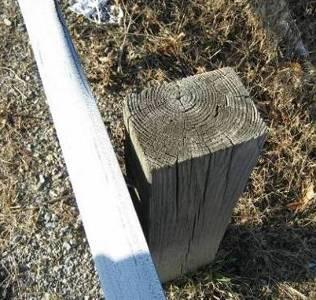
5 1. Introduction Prior to being considered acceptable for use on the nation s highway system, longitudinal barriers such as w-beam guardrails must demonstrate satisfactory crashworthiness in a series of full-scale crash tests. Procedures for determining the crashworthiness of longitudinal barriers in the US are set forth in NCHRP Report 350 [1] with analogous European crash test procedures prescribed in EN-1317 [2]. The intent of these test procedures is to evaluate the crash performance of a particular barrier under practical worst-case impact scenarios. The longitudinal barrier tests involve high speed oblique angle impacts with a small passenger car and a large pickup truck. The results of the tests are evaluated against specific criteria for the structural adequacy of the barrier, the vehicle trajectory as a result of the impact, and the potential for injury to vehicle occupants. Once longitudinal barriers are installed along a roadway, however, they often sustain minor damage. This includes small barrier deflections which may result from a low speed collision (Fig. 1) or damage resulting from routine highway maintenance operations, including snowplowing, mowing or paving. Since highway agencies operate with constrained resources, they must focus on repairing only damage that has a detrimental effect on the safety performance of the barrier. There is a critical need to know when damage to a longitudinal barrier constitutes the need for appropriate maintenance action to adequately protect occupants of a vehicle which departs the highway. Postponing repair of damage incorrectly believed to be minor may open the agency to tort liability claims. Unfortunately, the distinction between minor damage and more severe performance-altering damage is not always clear. Furthermore, crash testing experience of undamaged barriers has often demonstrated that seemingly insignificant alterations 3

6 to a barrier, such as using a rectangular washer on the post-rail connection, may result in catastrophic consequences for an impacting vehicle. Fig. 1. Minor damage to a strong post w-beam barrier on a major state route. There is a significant amount previous research on the crash performance of undamaged barrier. This includes numerous full-scale crash testing efforts (see Ray and McGinnis [3] for a broad summary of crash testing for various barrier types) as well as many studies using finite element simulation (see Reid [4] and Atahan [5] for more detailed reviews). There is very little known, however, regarding the crash performance of longitudinal barriers that have previously sustained minor damage of any type. The primary guidance for highway agencies regarding barrier repair is a 1990 Federal Highway Administration (FHWA) publication entitled W-Beam Guardrail Repair and Maintenance [6]. Although this document provides a quantitative description of what damage constitutes the need to repair damaged barrier, there is no documentation of an analytical or experimental basis for the recommended repair thresholds. Our understanding is that the guidelines were developed based on previous state experience with w-beam barrier and engineering judgment. National Cooperative Highway Research Program (NCHRP) Project [7] was tasked with developing repair guidelines, based on an analytic and experimental foundation, to better assist highway personnel tasked with maintaining these barrier systems. 4
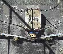
7 A better understanding of the influence of minor damage on the crash performance of longitudinal barriers is needed. While full-scale crash testing is the traditional mechanism of investigating barrier crash performance, this type of test is a costly undertaking requiring both the purchase of a vehicle and installation of a full-length longitudinal barrier. As part of the NCHRP Project research effort, this paper examined pendulum testing as a surrogate method of evaluating the effects of minor damage on the crash performance of longitudinal barrier. 2. Objective The purpose of this study was twofold: (1) to develop a pendulum test methodology to evaluate the effect of minor damage on the performance of w-beam barrier, and (2) use this test methodology to assess the effect of several different damage modes on the crash performance of strong post w-beam barrier. 3. Experimental Design Development and Test Methodology 3.1 Pendulum Apparatus and Impactor Face The pendulum tests used the pendulum device currently located at the FHWA Federal Outdoor Impact Laboratory (FOIL) in McLean, Virginia. The FOIL pendulum consisted of a support structure, a 2000-kg (4500 lb) pendulum mass (center image in Fig. 2), and two rigid posts (left image in Fig. 2) located on either side of the suspended pendulum mass. A rounded triangular pendulum impactor face was fabricated for the tests (right image in Fig. 2). The radius of chamfer at the impactor face center was 152 mm (6 inches), which was based on measurements of a 2006 Chevrolet 1500 pickup truck. The impactor face was 420 mm (16.5 inches) tall and was capable of engaging the full w-beam cross section. The combined mass of 5
 recommended mass limit specified by NCHRP Report 350 for the 2000P test vehicle. Fig. 2. Existing rigid posts (left), FOIL pendulum mass (center), and new impactor face (right).")

![Specific dimensions of the w-beam cross section can be found in drawing RWM02a of the Standardized Highway Barrier Hardware Guide [9].](/docs-images/86/93873684/images/8-2.jpg "The posts were A36 steel, conforming to AASHTO M 270 / M 270M [10], and had a W150x13.5 (W6x9) cross section, conforming to AASHTO M 160 / M 160M [11].")
8 pendulum and the impactor face was kg (4,545 lbs) to represent the mass of the NCHRP Report kg pickup truck (2000P) test vehicle. Note that the pendulum mass was slightly higher than the 2045 kg (4508 lbs) recommended mass limit specified by NCHRP Report 350 for the 2000P test vehicle. Fig. 2. Existing rigid posts (left), FOIL pendulum mass (center), and new impactor face (right). 3.2 W-Beam Test Section, Anchorage and Embedment A two-post section of modified G4(1S) strong post w-beam barrier with wood blockouts was selected for testing. The steel w-beam sections used conformed to AASHTO M 180 Class A requirements [8]. Specific dimensions of the w-beam cross section can be found in drawing RWM02a of the Standardized Highway Barrier Hardware Guide [9]. The posts were A36 steel, conforming to AASHTO M 270 / M 270M [10], and had a W150x13.5 (W6x9) cross section, conforming to AASHTO M 160 / M 160M [11]. The blockouts were 150 mm x 200 mm x 360 mm (6 inches x 7.75 inches x 14 inches) with a stress grade of at least 8 MPa (1160 psi). Additional details on the posts and blockouts can also be found in drawings PWE01 and PDB01b of the Standardized Highway Barrier Hardware Guide [9], respectively. The strong post w-beam barrier was selected as it was found to be the most common barrier used in the United States [12]. 6
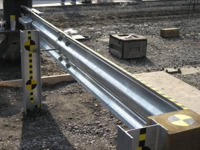
9 The barrier test section length was constrained by the available span, approximately 5.5 m (18 feet), between the existing rigid posts on either side of the FOIL pendulum. Using standard 1905 mm (6.25 feet) post spacing and 3810 mm (12.5 feet) rail lengths, this allowed for one post to be located at a rail splice and the other post a non-splice location. As this section represents the smallest repeating unit for the strong post w-beam barrier, this configuration was thought to be most representative of a typical full-length installation. Note that this two post section is roughly one tenth the length of a barrier in a full-scale crash test, which typically has 29 posts. The w-beam section was oriented such that the impact was mid-span between the two posts. Fig. 3 is a schematic of the overall test setup. The overall rail length is approximately 5 meters (198 inches) and each post was 1830 mm (6 feet) in total length. Fig. 3. Overall Pendulum Test Setup Developing an appropriate method to anchor each end of the test section to the rigid posts proved to be most challenging portion of the test setup. The goal was to replicate a two post section as if it was within a full length barrier section, which requires each end of the test section some freedom to both translate and rotate. Due to the close proximity of the rigid posts on either side of the pendulum, the primary focus was on designing the end fixture to allow rotation of each end of the w-beam test section. Also, an effort was made to use as much standard guardrail 7
 swaged cable typically used to anchor w-beam terminals (left image of Fig. 4).")
![Additional details on the cable anchor brackets and swaged cable can be found in drawings FPA01 and FCA01 of the Standardized Highway Barrier Hardware Guide [9], respectively.](/docs-images/86/93873684/images/10-1.jpg "This end anchor configuration was originally selected to ensure w-beam rail rupture would occur before failure of the anchorage.")

10 hardware as possible in the end fixture design. The original end fixture design selected consisted of 3 standard cable anchor brackets and a 910 mm (3 foot) version of the standard 2000 mm (6.5 foot) swaged cable typically used to anchor w-beam terminals (left image of Fig. 4). Additional details on the cable anchor brackets and swaged cable can be found in drawings FPA01 and FCA01 of the Standardized Highway Barrier Hardware Guide [9], respectively. This end anchor configuration was originally selected to ensure w-beam rail rupture would occur before failure of the anchorage. Later, an alternative 2-cable end fixture design was developed (center image in Fig. 4). A comparison of two undamaged section pendulum tests showed no discernable difference in deflection. The 2-cable end fixture proved to be robust and was used in the remainder of the tests to simplify the test setup and reduce costs. As experience was gained in conducting these tests, several minor modifications were made to the 2-cable end fixture, primarily to prevent tearing and bending failures within the fixture. Larger 82.6 mm (3.25 inch) outside diameter washers were used inside the rigid posts to prevent pullout of the cables from the rigid posts. The length of swaged cables was increased by 102 mm (4 inches) so the cable would bend instead of the swage. To prevent tearing in the fixture, the typical washers used in conjunction with the anchor brackets were replaced by an anchor plate. Results from pendulum tests conducted using both the 2-cable and 3-cable end fixture schemes will be presented herein. Cable Anchor Bracket Soil Box 8
11 Fig. 4. Three cable (left) and two cable (center) w-beam end fixture and soil box (right) As the anchor points on the existing rigid posts were higher than the standard w-beam rail height, a soil box (right image in Fig. 4) was used to raise the ground level around the posts by 178 mm (7 inches). The soil box was constructed of four 38 mm x 235 mm x 2.44 m (2 inches x 10 inches x 8 feet) pine boards and supported on each side by steel rebar to provide the soil restraining force such that proper compaction could be attained. As specified by NCHRP Report 350, the soil used in the test conformed to AASHTO M [13]. A mechanical tamper was used to compact the soil surrounding each W150x13.5 (W6x9) steel post in 150 mm (6 inch) lifts. A nuclear density gauge (Troxler Model 3440) was used to determine the compaction and soil properties of each soil lift for each post. For each lift, the preferred compaction level was 95 percent. 3.3 Instrumentation and Data Analysis Instrumentation and data collection for all tests conformed to NCHRP Report 350 [1] requirements. In each test, two accelerometers were located at the rear of the pendulum mass (Endevco model 7265A). Both accelerometers were in-line with the pendulum center of gravity and were aligned in the pendulum direction of travel. Tri-axial accelerometers, consisting of 3 Endevco model 7265A or model 7264B-2000 accelerometers, were placed on each rigid post to quantify the motion of the rigid posts during the pendulum impact. All accelerometers had a minimum range of ± 981 m/s 2 (100 G s) and all acceleration data was sampled at 10,000 Hz using a Diversified Technical Systems (DTS) TDAS Pro data acquisition system. Identification of the time of initial contact of the pendulum mass to the test section was accomplished through the use of pressure sensitive switches located on the top hump of the w-beam at the center of the test section. 9
12 Four high speed cameras, two NAC Memrecam fx K3 cameras and two NAC Memrecam fx K3R cameras, were used in all tests to capture the behavior of the w-beam section during the impact. All high speed video was recorded at 500 frames per second at a resolution of 1280 x Each test had a minimum of two common camera views: (1) a top view of the middle of the w-beam section and (2) a perpendicular rear view of the entire w-beam section. The other two high speed camera views varied between tests depending on the location of the minor damage. In addition, a real time camera was used to capture a perspective view of each test. For all acceleration data, a pre-sample filter with channel frequency class (CFC) 3000 Hz was applied during data collection. Each channel was then bias adjusted by averaging the acceleration prior to pendulum release and subtracting that value from each data point. Before plotting acceleration data for comparison purposes, the data was filtered using a Butterworth 4- pole phaseless digital filter with CFC 60, according to SAE J-211 [14]. Prior to numerical integration, the raw acceleration data was filtered using a Butterworth 4-pole phaseless digital filter with CFC 180. After filtering, the primary and redundant acceleration data for each test was compared visually to ensure reasonable agreement, i.e. no clipping or channel failure, and then averaged to generate a single pendulum response. For each test, this single pendulum response, filtered to CFC 180, was used for the remainder of the computations described below. Pendulum impact velocity in all tests was determined by numerically integrating the pendulum-mounted acceleration data from the time of pendulum release to the time of impact. This value was checked against the theoretical velocity of the pendulum computed using the pendulum mass and the pendulum height difference, between the release point and impact point, recorded for each test. In all cases, the computed impact velocity was lower than the theoretical velocity; the average difference was approximately 4 percent with a maximum difference of 8 10
13 percent. Note that the results of the pendulum tests as presented in [7] provided only estimated impact velocity values. Barrier deflection at the impact location was determined by numerically integrating the pendulum velocity. For cases where the pendulum penetrated the barrier test section, the time of penetration was estimated using the overhead high speed video. In these instances, the barrier deflection was only shown up to the point of penetration. The impact force on the pendulum was computed by multiplying the pendulum acceleration by the pendulum mass. This force was then plotted as a function of the computed displacement and integrated to provide an estimate of the energy imparted to the pendulum by the barrier test section. 3.4 Impact Conditions and Relevance to Full-Scale Crash Testing The FOIL pendulum was not capable of reproducing the significant motion along the length of the barrier test section that is characteristic of an oblique impact prescribed by the NCHRP Report 350 longitudinal barrier test procedures. As such, the pendulum tests were primarily used to evaluate the performance of a damaged two-post barrier section compared to an undamaged section tested in the same impact configuration. Because of the perpendicular impact configuration, the pendulum tests were only used to evaluate the structural adequacy of barrier test section. Other relevant barrier performance factors, such as wheel snagging, vehicle rollover, and occupant risk, could not be evaluated using this pendulum test methodology. There was an effort, however, to design the pendulum impact conditions to match the lateral energy produced in a NCHRP 350 redirectional test; this is illustrated below in Fig
14 Fig. 5. Comparison of NCHRP 350 (left) and pendulum impact (right) scenarios Pendulum tests were conducted at two impact speeds: 32.2 km/hr (20 mph) and 28.2 km/hr (17.5 mph). A 32.2 km/hr (20 mph) impact speed was originally selected to approximate the lateral forces that would result from a 2000 kg (4500 lb) test vehicle impacting at 100 km/hr (62 mph) and 20 degrees. Assuming that all the impact energy is absorbed in a 2 post section of a full-scale test barrier, these conditions represent a lateral impact speed approximately 75 percent that of an NCHRP 350 Test 3-11 impact (100 km/hr and 25 degrees). The constraining factor was the maximum speed of the FOIL pendulum, which is 32.2 km/hr (20 mph). The speed is limited by the maximum height to which the pendulum can be raised. The pendulum impacts, however, were more severe than a full-scale crash test for two primary reasons: (1) the pendulum test section was a more rigid system, and (2) the impact energy was distributed over a smaller area. The end fixtures attaching each end of the w-beam test section to the rigid posts allowed only minimal longitudinal translation of the rail section in contrast to the full-scale test where the posts surrounding the impact area deflect, reducing the tension in the rail and splices. Second, in a pendulum test, all the impact energy was absorbed by a single two post (1905 mm) barrier section. In several full-scale tests analyzed, however, the lateral energy was primarily distributed over two to four of these 1905 mm (6.25 foot) barrier 12
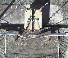
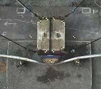
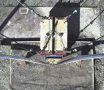
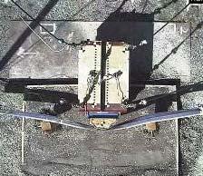
15 sections. To account for this distributed loading, the pendulum impact speed was reduced to 28.2 km/hr (17.5 mph). This impact speed conservatively assumes that the lateral impact energy in a full-scale test was absorbed by two 1905 mm (6.25 foot) barrier sections; each section absorbing half the vehicle lateral kinetic energy. 4. Test Plan and Barrier Damage Modes A total of 3 undamaged barrier baseline tests were run: (1) a 32.2 km/hr (20 mph) baseline impact into an undamaged two-post barrier section with the 3-cable end fixture, (2) a 32.2 km/hr (20 mph) baseline impact into an undamaged two-post barrier section with the 2- cable end fixture, and (3) a 28.2 km/hr (17.5 mph) baseline impact into an undamaged two-post barrier section with the 2-cable end fixture. Eleven tests of damaged barrier were conducted to evaluate five different barrier damage modes. These five damage modes represent a subset of ten damage modes investigated under NCHRP Project [7]. A survey of US and Canadian transportation agencies [12], which provided anecdotal evidence of the frequency of various damage modes, served as the basis for selection of the ten evaluated damage modes. Pendulum testing was elected for those damage modes where tearing or fracture was likely, as finite element simulation is a less than ideal method of modeling this type of damage. Table 1 presents a field example of each of the five evaluated damage modes and the analogous pendulum test setup. Note that the remaining damage modes were evaluated using either finite element simulation of full-scale barrier tests or limited full-scale barrier testing; see [7] for additional details on the damage modes not contained herein. 13


16 Table 1 Tested Barrier Damage Mode Damage Mode Field Example Pendulum Test Setup Vertical Tear Horizontal Tear Splice Damage Twisted Blockout Missing Blockout 14
17 With the exception of the splice damage, each damage mode was tested with the 3-cable and 2-cable end fixtures. All 3-cable tests were at a speed of 32.2 km/hr (20 mph) while the 2- cable tests were either at 32.2 km/hr (20 mph) or 28.2 km/hr (17.5 mph). For the purpose of the pendulum tests, the barrier damage modes were artificially induced, e.g. not through an impact typical of a field installation. This method was selected based on the damage modes to be evaluated through pendulum testing and the ability to better control the exact level of damage induced to a barrier test section. A more detailed description of how each damage mode was created is described below: Vertical Tear Damage: A vertical tear was simulated by cutting a slit in the w-beam using a reciprocating saw. The point at the end of the slit was intended to provide a stress concentrator similar to those observed in the field in a crash-induced vertical tear. In all vertical tear tests, the location of the tear corresponded to the pendulum mass impact location, as this was believed to have the largest risk for rail rupture. Two different length tears were tested: a 102 mm (4 inch) tear and a 13 mm (0.5 inch) tear. All tears started from the top of the w-beam section. For the 102 mm tear, the width of the tear was 13 mm (0.5 inches) at the w-beam edge and tapered to a point. For the 13 mm (0.5 inch) tear, the width of the tear was approximately 4 mm (0.15 inches). Splice Damage: Splice damage was simulated by removing a rectangular block of material directly in line with a single splice bolt and having width equal to the diameter of the splice bolt. The intent was to simulate complete loss of bearing capacity for a single bolt (of 8 bolts total) in the splice connection. Horizontal Tear Damage: A horizontal tear was simulated by cutting a longitudinal notch in the center of the upper protrusion of the w-beam using a reciprocating saw. Each end 15
18 of the notch was tapered to a point to provide a stress concentrator similar to those observed in the field in a crash-induced horizontal tear. The location of the tear corresponded to the pendulum mass impact location, as this was believed to have the largest risk for rail rupture. The horizontal tear was a total of 306 mm (12 inches) long. The middle 204 mm (8 inches) of the tear was 13 mm wide (0.5 inches) with a 51 mm (2 inch) taper on either end. Twisted Blockout Damage: In this case, the routed wooden blockout at the splice was installed rotated about the post-rail bolt. The blockout was rotated approximately 45 with respect to the vertical in all tests. Missing Blockout Damage: For this damage mode, the blockout at the splice location was not installed. The post-rail bolt remained connected to simulate a wooden blockout that had split completely and was no longer present. In both tests, there was approximately 178 mm (7 inches) of separation between the near flange of the post and the back of the w-beam rail. The splice location was thought to be the critical case as the splice is the weakest link in the rail element. 5. Results Pendulum testing results are presented primarily for the 2-cable anchored tests as these tests included the lower speed tests that are more representative of a 2000P vehicle impacting a full-length barrier at NCHRP Report 350 TL-3 conditions. Table 2 presents a brief summary of the pendulum testing. 16
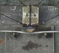
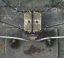
19 Table 2 Pendulum Testing Summary Damage Mode Test # Anchorage Undamaged Vertical Tear (102 mm) Vertical Tear (13 mm) Horizontal Tear Impact Speed [km/hr] Maximum Deflection* [mm] Time of Max Deflection [ms] Energy [kj] Crash Performance Cable Containment Cable Containment Cable Containment Cable * Penetration, Tear at center Cable * Penetration, Tear at center Cable Containment, Tear at center Cable * Penetration, Splice Failure Cable Containment Splice Damage Cable Containment Twisted Cable Containment Blockout Cable Containment Containment, Cable Tear at splice Missing Blockout Cable * Penetration, Splice Failure Cable Containment * If penetration, maximum deflection refers to deflection just prior to penetration 5.1 Baseline Tests In test 03-2, the undamaged barrier contained the pendulum mass impacting at 30.1 km/hr (18.7 mph). The maximum dynamic deflection of the test section was 658 mm (25.9 inches) at 131 ms after the initial impact. The maximum static crush at the center of the w-beam was 356 mm (14.0 inches). The overall damage and individual post damage is shown in Fig. 6. The post at the splice location (center in Fig. 6) experienced more torsion than the non-splice post and had some minor cracking at the flange. The post at the splice location also remained connected to the rail while the post bolt at the non-splice location pulled through the slot in the rail. There were no failures in the anchor cables in this test and there was no visible separation of the cable from the swaged portion of the anchor cable assembly. At the splice location, there was approximately 19 mm (0.75 inches) of relative movement between the two w-beam rail 17
 and Fig.")
.")

20 sections. No tears were evident in the guardrail and no bolt failure was observed. The left portion of Fig. 7 shows time sequential snapshots of test 03-2 obtained from the high speed camera positioned overhead. Fig. 8 (a) and Fig. 9 (a) show the measured pendulum acceleration and barrier center deflection for all three undamaged barrier baseline tests, respectively. The force on the pendulum mass as a function of barrier center deflection for these tests is shown in Fig. 10 (a). In general, the remaining two undamaged barrier tests (no photos shown) had similar results to test Tests 01-2 and 07-1 both had successful containment of the pendulum mass. In both tests, the post-rail connection at the splice remained intact and post-rail bolt pullout was evident at the non-splice location. The separation at the splice was also approximately 19 mm (0.75 inches) in both tests. For test 01-2, both the impact speed and maximum deflection were slightly higher compared to the analogous 2-cable test (Test 03-2, see Table 2). Fig. 6. Test 03-2: Overall damage (right) and post damage at splice (center) and non-splice location (right) Fig. 7. Sequential overhead photographs for undamaged section (left) and 102 mm vertical tear damage (right) Fig. 8. Pendulum acceleration as a function of time for (a) undamaged section tests, (b) vertical tear damage tests, (c) horizontal tear damage tests, (d) splice damage test, (e) twisted blockout tests, and (f) missing blockout tests. Fig. 9. Barrier center deflection for (a) undamaged section tests, (b) vertical tear damage tests, (c) horizontal tear damage tests, (d) splice damage test, (e) twisted blockout tests, and (f) missing blockout tests. 18
 undamaged section tests, (b) vertical tear damage tests, (c) horizontal tear damage tests, (d) splice damage test, (e) twisted blockout")
.")
 at 90 ms after initial impact, which was just prior to penetration of the w-beam section.")
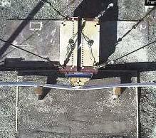
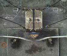
21 Fig. 10. Force on pendulum as a function of barrier deflection for (a) undamaged section tests, (b) vertical tear damage tests, (c) horizontal tear damage tests, (d) splice damage test, (e) twisted blockout tests, and (f) missing blockout tests. 5.2 Vertical Tear Damage In test 03-5, the barrier section with a 102 mm (4 inch) vertical tear was unable to contain the pendulum mass impacting at 32.0 km/hr (19.9 mph). A vertical tear developed from the bottom tip of the induced vertical tear and continued (approximately straight downward) through the entire w-beam cross section resulting in a complete transection of the w-beam at the impact location. The deflection of the rail was 651 mm (25.6 inches) at 90 ms after initial impact, which was just prior to penetration of the w-beam section. At 118 ms after initial impact, the w-beam was completely transected. Fig. 11. Test 03-5: Overall damage (left) and post damage at splice (center) and non-splice location (right) The overall damage and the post damage due to impact are shown in Fig. 11. Compared to undamaged rail, the posts experienced less torsion and did not fracture. The post-rail bolt pulled out of the rail at the non-splice location. At the splice location the post-rail connection remained intact despite large deformation of the bolt. There was 6 to 13 mm (0.25 to 0.50 inches) of relative movement between the two w-beams at the splice location. Other than at the damage location, there were no other tears evident in the beam. Also, there was no relative movement between the cable and swage of any anchor cable assembly. The right portion of Fig. 19
, test 01-3, was very similar with the pendulum penetrating the barrier section due to a full cross section tear at the impact location.")


22 7 shows time sequential snapshots of test 03-5 obtained from the high speed camera positioned overhead. The performance of the analogous 3-cable test (no photos shown), test 01-3, was very similar with the pendulum penetrating the barrier section due to a full cross section tear at the impact location. Post damage and relative movement of the w-beam sections at the splice was similar. Again, the post-rail connection at the splice remained intact while the post-rail bolt pulled through the rail at the non-splice location. For the 13 mm (0.5 inch) vertical tear damage in test 08-2, the barrier was able to contain the pendulum mass with a maximum deflection of 723 mm (28.5 inches). A vertical tear developed from the bottom tip of the induced vertical tear, at 13 mm (0.5 inches) from the w- beam edge, and continued (roughly straight downward) through approximately half of the w- beam cross section. The overall damage and close-up views of the tear propagation are shown in Fig. 12. Fig. 8 (b) and Fig. 9 (b) show the measured pendulum acceleration and barrier center deflection for all three vertical tear tests, respectively. The force on the pendulum mass as a function of barrier center deflection for the vertical tear tests are shown in Fig. 10 (b). Fig. 12. Test 08-2: Overall damage (left) and detail views of the additional tearing caused by the pendulum impact (center and right) 20
 at 134 ms after the initial impact, computed from the pendulum acceleration data.")
 of relative movement between the two w-beams at the splice location. The left portion of Fig.")
 show the measured pendulum acceleration and barrier center deflection, respectively, for both horizontal tear tests conducted.")
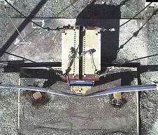
23 5.3 Horizontal Tear Damage The horizontal tear damaged barrier in test 07-3 contained the pendulum mass impacting at 26.8 km/hr (16.7 mph). The maximum dynamic deflection of the test section was 618 mm (24.3 inches) at 134 ms after the initial impact, computed from the pendulum acceleration data. The maximum static crush at the center of the w-beam was 406 mm (16.0 inches). The damage at the impact location and individual post damages are shown in Fig. 13. Both post-rail connections remained intact and there was 16 mm (0.63 inches) of relative movement between the two w-beams at the splice location. The left portion of Fig. 14 shows time sequential snapshots of test 07-3 obtained from the high speed camera positioned overhead. Fig. 8 (c) and Fig. 9 (c) show the measured pendulum acceleration and barrier center deflection, respectively, for both horizontal tear tests conducted. The force on the pendulum mass as a function of barrier center deflection for the vertical tear tests are shown in Fig. 10 (c). Fig. 13. Test 07-3: Detail view of impact location (left) and post damage at splice (center) and non-splice location (right) Fig. 14. Sequential overhead photographs for horizontal tear damage (left) and splice damage (right) In test 02-1, the horizontal tear damaged barrier (overhead sequence not shown) was unable to contain the pendulum mass impacting at 32.0 km/hr (19.9 mph). The deflection of the 21

 and post damage at splice (center) and non-splice location (right) 5.")
 at 135 ms after the initial impact.")
24 rail was 738 mm (29.1 inches) at 102 ms after the initial impact, which was just prior to penetration of the w-beam section. The barrier section failed at the splice due to the splice bolts pulling through holes in the rail with none of the individual splice bolts fracturing. At both the splice and non-splice location, the post bolt pulled through the rail element. The splice failure and post damage is shown in Fig. 15. Fig. 15. Test 02-1: Detail view of splice failure (left) and post damage at splice (center) and non-splice location (right) 5.4 Splice Damage In test 07-4, the splice damaged barrier contained the pendulum mass impacting at 26.8 km/hr (16.7 mph). The maximum dynamic deflection of the test section was 610 mm (24 inches) at 135 ms after the initial impact. Both post-rail connections remained intact and no serious splice separation was observed in the splice damage created prior to the impact. There was approximately 13 mm (0.5 inches) of relative movement between the two w-beams at the splice location. A detailed view of the splice damage and the individual post damage is shown in Fig. 16. The right portion of Fig. 14 shows time sequential snapshots of the test obtained from the overhead camera. Fig. 8 (d) and Fig. 9 (d) show the measured pendulum acceleration and barrier center deflection, respectively, for this test. The force on the pendulum mass as a function of barrier center deflection for the splice damage test is shown in Fig. 10 (d). 22
. The maximum dynamic deflection was 684 mm (26.")


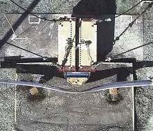
25 Fig. 16. Test 07-4: Detail view of splice bolt damage after test (left) and post damage at splice (center) and nonsplice location (right) 5.5 Twisted Blockout Damage In test 03-8, the twisted blockout damaged barrier contained the pendulum mass impacting at 30.4 km/hr (18.9 mph). The maximum dynamic deflection was 684 mm (26.9 inches) at 134 ms after the initial impact. The maximum static crush at the center of the w-beam was 356 mm (14 inches). The overall damage and the post damage due to impact are shown in Fig. 17. The left portion of Fig. 18 shows time sequential snapshots of test 03-8 obtained from the overhead high speed camera. The posts experienced similar damage to that in previous tests that contained the pendulum. The post at the splice location experienced more torsion than the non-splice post and had some minor cracking at the flange. The post at the splice remained connected to the rail while the post-rail bolt at the non-splice location pulled out of the slot in the rail. There were no failures in the anchor cables in this test and there was no separation of the cable from the swage portion of the anchor cable assembly. Splice separation was similar to previous tests, approximately 19 mm (0.75 inches) of relative motion between the w-beam sections. No tears developed in the guardrail and no bolts failed. The analogous 3-cable test (no photos shown), test 02-2, also contained the pendulum mass with very similar impact performance. Fig. 8 (e) and Fig. 9 (e) show the measured pendulum acceleration and barrier center deflection, 23
 and post damage at splice (center) and non-splice location (right) Fig. 18.")
, the barrier was unable to contain the pendulum mass impacting at 30.5 km/hr (19.0 mph).")

26 respectively, for both twisted blockout tests conducted. The force on the pendulum mass as a function of barrier center deflection for both twisted blockout tests are shown in Fig. 10 (e). Fig. 17. Test 03-8: Overall damage (left) and post damage at splice (center) and non-splice location (right) Fig. 18. Sequential overhead photographs for twisted blockout damage (left) and missing blockout damage (right) 5.6 Missing Blockout Damage For the missing blockout damage, two 2-cable tests were performed. In the first test (test 03-7), the barrier was unable to contain the pendulum mass impacting at 30.5 km/hr (19.0 mph). The barrier section failed at the splice due to the splice bolts pulling through holes in the rail with none of the individual splice bolts fracturing. This failure was similar to that observed in test 02-1 with the horizontal tear damaged section. The deflection of the rail was approximately 691 mm (27.2 inches) at 106 ms after the initial impact, which was just prior to penetration of the w- beam. At 116 ms, the splice was completely separated. The deformation of the posts was less than in the undamaged section test, as there was almost no torsion experienced by the post at the splice location. There was no visible cracking of either post. As with most previous tests, the post-rail bolt pulled through the w-beam rail at the non-splice location. The post-rail bolt at the non-splice location experienced large bending 24


 and post damage at splice (center) and non-splice location")
. The deflection of the rail was approximately 633 mm (24.")

, detail view of damage at splice (center) and post damage at")
27 deformation while the bolt at the splice location fractured in the threaded region. Fig. 19 shows the post damage and the splice failure. No tear developed and none of the bolts failed, but rather the bolt holes deformed enough to allow the two sections to separate. The right portion of Fig. 18 shows time sequential snapshots of the test 03-7 obtained from the overhead high speed camera. Fig. 19. Test 03-7: splice failure (left) and post damage at splice (center) and non-splice location (right) In the second test (overhead sequence not shown), the barrier was able to contain the pendulum mass impacting at 26.7 km/hr (16.6 mph). The deflection of the rail was approximately 633 mm (24.9 inches) at 132 ms after the initial impact. Damage that the barrier section sustained in Test 07-5 is shown below in Fig. 20. Fig. 20. Test 07-5: overall damage (left), detail view of damage at splice (center) and post damage at non-splice location (right) In test 01-4, the barrier had a different impact performance. The barrier section contained the pendulum mass impacting at 31.5 km/hr (19.6 mph). The maximum dynamic deflection of the rail was 719 mm (28.3 inches) at 126 ms after the initial impact. The asymmetry caused by 25
 in length, approximately two-thirds of the total w-beam cross section, and along the line of the splice bolts.")
 show the measured pendulum acceleration and barrier center deflection, respectively, for the missing blockout tests conducted.")
, rail tear at splice (center), and post damage at splice location (right) 6.")
28 the missing blockout resulted in a significant twisting of the pendulum (approximately 6 degrees) in the horizontal plane. The vertical tear that developed at the splice location was 229 mm (9 inches) in length, approximately two-thirds of the total w-beam cross section, and along the line of the splice bolts. A close-up of the tear is shown in the center image in Fig. 21. Fig. 8 (f) and Fig. 9 (f) show the measured pendulum acceleration and barrier center deflection, respectively, for the missing blockout tests conducted. The force on the pendulum mass as a function of barrier center deflection for the missing blockout tests are shown in Fig. 10 (f). Fig. 21. Test 01-4: overall damage (left), rail tear at splice (center), and post damage at splice location (right) 6. Discussion In all three baseline tests, the undamaged barrier section demonstrated satisfactory impact performance by containing the pendulum mass. The cable end fixture designs provided adequate connection of the w-beam section to the existing rigid posts on either side of the pendulum. With the exception of the shorter swaged cables, the end fixtures were constructed with standard barrier hardware. The cable end fixtures provide a very rigid connection of the w-beam to the essentially rigid posts on either side of the pendulum. Based on an analysis of data from the rigid post mounted accelerometers, the maximum motion of each rigid post was approximately 1 inch (data not shown) toward the pendulum mass, which would have a tendency to slightly 26
29 reduce the tension in the w-beam rail. This rigid connection coupled with the 32.2 km/hr (20 mph) pendulum impact speed, though, provides a very severe impact to the barrier section, which approaches the limit of the strong post barrier section. The ability of the w-beam barrier to withstand an impact of this severity is a testament to its structural robustness. The pendulum tests appear to be an appropriate surrogate for determining the structural adequacy of w-beam barriers. A limitation of this test methodology is an inability to evaluate vehicle trajectory/stability as well as occupant risk. Most importantly, these tests provide insight into the crash performance of modified G4(1S) strong post w-beam barrier that has sustained minor damage. Several of these damage modes have been tested with repeated tests, albeit with slightly different impact speeds. A discussion of the effects of the different damage modes on the crash performance of the barrier is presented below. Vertical Tear Damage: W-beam rupture was observed in both 32.2 km/hr (20 mph) tests. While the induced tear at the impact location was roughly one third of the w-beam cross section, it is likely that any rail tear could cause a stress concentrator sufficient to cause rail rupture. In our testing, this was demonstrated by a third test; a 13 mm (0.5 inch) tear propagated to the midpoint of the w-beam cross section. In full-scale crash testing, a small tear at the bottom of the rail (caused by contact with the post during the test) was linked to rail rupture in a full-scale test conducted to develop the improved TL-3 version of the weak post w-beam barrier [16]. Based on this information, our recommendation is that vertical rail tears significantly affect the structural adequacy of the barrier and should be repaired. Horizontal Tear Damage: Although splice failure was observed in the 32.2 km/hr (20 mph) test, there was no evidence of rail rupture near the location of the horizontal tear. 27
30 In the 28.2 km/hr (17.5 mph) test, the damaged barrier was able to contain the impacting pendulum mass. Based on this information, our recommendation is that horizontal tears less than 306 mm (12 inches) in length and 13 mm (0.5 inches) in width do not significantly alter the performance of the barrier. Given the splice failure observed in the higher speed test, this damage should be repaired with a medium priority. Splice Damage: Splice damage was simulated such that one of the eight bolts in the splice connection had lost all available bearing capacity. In a 28.2 km/hr (17.5 mph) test, this barrier was able to contain the impacting pendulum mass with performance indistinguishable from the undamaged barrier section. Full-scale crash testing as well as the splice failures observed in the pendulum tests suggests the splice is a weak point in guardrail system. In light of this, our recommendation is that splice damage, where at least one bolt has compromised bearing capacity, be repaired with a medium priority. Twisted Blockout Damage: The performance of the barrier section with this damage was indistinguishable from that of the undamaged barrier section in two higher speed tests conducted suggesting that this damage mode has little effect on the structural adequacy of the barrier. Based on this information, our recommendation is that twisted blockout damage does not significantly alter the structural performance of the barrier and, as a result, is a low priority repair. Missing Blockout Damage: The crash performance of a barrier section with a missing blockout at the splice was marginal to unacceptable for the higher speed tests. One test (01-4) resulted in a rail tear at the splice through a majority of the cross section while the other test (03-7) resulted in a splice failure due to pullout of the splice bolts. This difference in impact performance was likely a result of the use of the splice bolt washers 28
31 in test The washers would allow additional tension to develop in the rail, ultimately leading to a rail tear as opposed to the bolt pullout splice failure observed in the other test. The lower speed test resulted in performance indistinguishable from the undamaged barrier. Our recommendation is that a missing blockout, especially at the splice, should be repaired with a medium priority based on the marginal performance of the barrier at the higher impact speed. 7. Conclusions This study presents a test methodology and a first-of-a-kind evaluation of the crash performance of strong post w-beam barrier that has sustained minor damage. Using the described test methodology, pendulum tests were conducted on a two-post section of strong post w-beam barrier sections with five types of damage: (1) vertical tear, (2) horizontal tear, (3) splice damage, (4) twisted blockout, and (5) missing blockout. Based on the results of the pendulum tests, vertical tears were found to be a significant threat to the structural adequacy of the barrier section with a high likelihood for rail rupture. A missing blockout at the splice location was found to result in marginal performance at the 32.2 km/hr (20 mph) impact speed with one test resulting in a large rail tear and another in a splice failure. Horizontal tears less than 306 mm (12 inches) long and 13 mm (0.5 inches) wide and splice damage with one bolt lacking bearing capacity were found to have a less significant threat on the structural adequacy of the barrier. Both of these damage modes had acceptable performance at the 28.2 km/hr (17.5 mph) impact speed. Twisted blockout damage was found to have no effect on the structural crash performance of the strong post w-beam barrier. 29
32 8. Acknowledgements This research was sponsored by the National Academy of Sciences under the National Cooperative Highway Research Program (NCHRP) Project 22-23, Criteria for Restoration of Longitudinal Barriers. The authors wish to acknowledge the guidance of Charles W. Niessner, program manager for NCHRP Project 22-23, as well as the insight of the project panel. The FHWA supported this effort by making the FOIL facility available for the testing and allowing contract staff of the National Crash Analysis Center (NCAC) from George Washington University to assist in the setup and execution of the tests. We would also like to thank the NCAC staff including Pradeep K. Mohan (Senior Researcher) as well as Chris Story, Scott Mosser, and Eduardo Arispe (FOIL Technicians). We would also like to thank Trinity Industries, Inc. and Gregory Industries, Inc. for providing the guardrail materials for these pendulum tests. We also acknowledge Greg Webster, Craig Thor for their help conducting the pendulum tests. 9. References 30
33 [1] Ross, Hayes E., Sicking, D.L., Zimmer, R.A., and J.D. Michie. Recommended Procedures for the Safety Performance Evaluation of Highway Features. NCHRP Report 350, TRB, National Research Council, Washington, D.C., [2] European Committee for Standardization (CEN). Road Restraint Systems Part 2: Performance Classes, Impact Test Acceptance Criteria and Test Methods for Safety Barriers. European Standard EN [3] Ray MH, McGinnis RG. Guardrail and Median Barrier Crashworthiness, NCHRP Synthesis 244, National Academy Press, Washington, DC, [4] Reid JD. LS-DYNA Simulation Influence on Roadside Hardware. Transportation Research Record 1890, Transportation Research Board, Washington, DC, 2004, pp [5] Atahan AO. Vehicle Crash Test Simulation of Roadside Hardware Using LS-DYNA: A Literature Review. International Journal of Heavy Vehicle Systems, Vol. 17, No. 1, [6] W-Beam Guardrail Repair and Maintenance: A Guide for Street and Highway Maintenance Personnel. FHWA-RT , Federal Highway Administration, U.S. Department of Transportation, [7] Gabler HC, Gabauer DJ, Hampton CE. Criteria for Restoration of Longitudinal Barriers: NCHRP Project Draft Final Report. December [8] American Association of State and Highway Transportation Officials (AASHTO). Standard Specification for Corrugated Sheet Steel Beams for Highway Guardrail, M , [9] A Guide to Standardized Highway Barrier Hardware, 2 nd Edition. AASHTO-AGC- ARTBA Joint Committee, Subcommittee on New Highway Materials, Task Force 13 Report, [10] American Association of State and Highway Transportation Officials (AASHTO). Standard Specification for Structural Steel for Bridges, M 270 / M 270M, [11] American Association of State and Highway Transportation Officials (AASHTO). General Requirements for Steel Plates, Shapes, Sheet Piling, and Bars for Structural Use, M 160 / M 160M, [12] Gabauer DJ, Gabler HC. Evaluation of Current Repair Criteria for Longitudinal Barrier with Crash Damage. Journal of Transportation Engineering, Vol. 135, No. 4, April [13] American Association of State and Highway Transportation Officials (AASHTO). Standard Specification for Materials for Aggregate and Soil-Aggregate Subbase, Base, and Surface Courses, AASHTO M , [14] Society of Automotive Engineers (SAE) Recommended Practice J211-1, Instrumentation For Impact Test Part 1 Electronic Instrumentation. SAE J211-1 (rev. July 2007). [15] Ray MH, Plaxico CA, Engstrand K. Performance of W-Beam Splices. Transportation Research Record 1743, Transportation Research Board, Washington, DC, 2001, pp [16] Ray MH, Engstrand K, Plaxico CA, McGinnis RG. Improvements to the Weak-Post W- Beam Guardrail. Transportation Research Record 1743, Transportation Research Board, Washington, DC, 2001, pp
34 32
35 List of Figures Fig. 1. Minor damage to a strong post w-beam barrier on a major state route. 4 Fig. 2. Existing rigid posts (left), FOIL pendulum mass (center), and new impactor face (right). 6 Fig. 3. Overall Pendulum Test Setup 7 Fig. 4. Three cable (left) and two cable (center) w-beam end fixture and soil box (right) 9 Fig. 5. Comparison of NCHRP 350 (left) and pendulum impact (right) scenarios 12 Fig. 6. Test 03-2: Overall damage (right) and post damage at splice (center) and non-splice location (right) 18 Fig. 7. Sequential overhead photographs for undamaged section (left) and 102 mm vertical tear damage (right) 18 Fig. 8. Pendulum acceleration as a function of time for (a) undamaged section tests, (b) vertical tear damage tests, (c) horizontal tear damage tests, (d) splice damage test, (e) twisted blockout tests, and (f) missing blockout tests. 18 Fig. 9. Barrier center deflection for (a) undamaged section tests, (b) vertical tear damage tests, (c) horizontal tear damage tests, (d) splice damage test, (e) twisted blockout tests, and (f) missing blockout tests. 18 Fig. 10. Force on pendulum as a function of barrier deflection for (a) undamaged section tests, (b) vertical tear damage tests, (c) horizontal tear damage tests, (d) splice damage test, (e) twisted blockout tests, and (f) missing blockout tests. 19 Fig. 11. Test 03-5: Overall damage (left) and post damage at splice (center) and non-splice location (right) 19 Fig. 12. Test 08-2: Overall damage (left) and detail views of the additional tearing caused by the pendulum impact (center and right) 20 Fig. 13. Test 07-3: Detail view of impact location (left) and post damage at splice (center) and non-splice location (right) 21 Fig. 14. Sequential overhead photographs for horizontal tear damage (left) and splice damage (right) 21 Fig. 15. Test 02-1: Detail view of splice failure (left) and post damage at splice (center) and nonsplice location (right) 22 Fig. 16. Test 07-4: Detail view of splice bolt damage after test (left) and post damage at splice (center) and non-splice location (right) 23 Fig. 17. Test 03-8: Overall damage (left) and post damage at splice (center) and non-splice location (right) 24 Fig. 18. Sequential overhead photographs for twisted blockout damage (left) and missing blockout damage (right) 24 Fig. 19. Test 03-7: splice failure (left) and post damage at splice (center) and non-splice location (right) 25 Fig. 20. Test 07-5: overall damage (left), detail view of damage at splice (center) and post damage at non-splice location (right) 25 Fig. 21. Test 01-4: overall damage (left), rail tear at splice (center), and post damage at splice location (right) 26 33
36 List of Tables Table Table


37 Undamaged Two-Post Section, 2-Cable Anchorage (30.9 km/hr) 102 mm Vertical Tear Damage, 2-Cable Anchorage (32.8 km/hr) 0.02 s 0.06 s 0.03 s 0.06 s 0.10 s 0.14 s 0.09 s 0.12 s 0.18 S s 0.15 s 0.18 s 0.26 S 0.30 s 0.21 s 0.24 s 35


38 Horizontal Tear Damage, 2-Cable Anchorage (29.3 km/hr) Splice Damage, 2-Cable Anchorage (29.3 km/hr) 0.02 s 0.06 s 0.02 s 0.06 s 0.10 s 0.14 s 0.10 s 0.14 s 0.18 S s 0.18 s 0.22 s 0.26 S 0.30 s 0.26 s 0.30 s 36


39 Twisted Blockout Damage, 2-Cable Anchorage (31.2 km/hr) Missing Blockout Damage, 2-Cable Anchorage (30.6 km/hr) s s s s S S s s S S S s s S s s 37
Crash Performance of Strong-Post W-Beam Guardrail with Missing Blockouts Carolyn E. Hampton and Hampton C. Gabler
 Crash Performance of Strong-Post W-Beam Guardrail with Missing Blockouts Carolyn E. Hampton and Hampton C. Gabler Virginia Tech Center for Injury Biomechanics, Blacksburg VA 24061 Abstract Missing blockouts
Advances in Simulating Corrugated Beam Barriers under Vehicular Impact
 13 th International LS-DYNA Users Conference Session: Automotive Advances in Simulating Corrugated Beam Barriers under Vehicular Impact Akram Abu-Odeh Texas A&M Transportation Institute Abstract W-beam
Manual for Assessing Safety Hardware
 American Association of State Highway and Transportation Officials Manual for Assessing Safety Hardware 2009 vii PREFACE Effective traffic barrier systems, end treatments, crash cushions, breakaway devices,
Development and Validation of a Finite Element Model of an Energy-absorbing Guardrail End Terminal
 Development and Validation of a Finite Element Model of an Energy-absorbing Guardrail End Terminal Yunzhu Meng 1, Costin Untaroiu 1 1 Department of Biomedical Engineering and Virginia Tech, Blacksburg,
Assessing Options for Improving Roadside Barrier Crashworthiness
 13 th International LS-DYNA Users Conference Session: Simulation Assessing Options for Improving Roadside Barrier Crashworthiness D. Marzougui, C.D. Kan, and K.S. Opiela Center for Collision Safety and
Working Paper. Development and Validation of a Pick-Up Truck Suspension Finite Element Model for Use in Crash Simulation
 Working Paper NCAC 2003-W-003 October 2003 Development and Validation of a Pick-Up Truck Suspension Finite Element Model for Use in Crash Simulation Dhafer Marzougui Cing-Dao (Steve) Kan Matthias Zink
A MASH Compliant W-Beam Median Guardrail System
 0 0 0 0 0 A MASH Compliant W-Beam Median Guardrail System By A. Y. Abu-Odeh, R. P. Bligh, W. Odell, A. Meza, and W. L. Menges Submitted: July 0, 0 Word Count:, + ( figures + tables=,000) =, words Authors:
Evaluation and Design of ODOT s Type 5 Guardrail with Tubular Backup
 Evaluation and Design of ODOT s Type 5 Guardrail with Tubular Backup Draft Final Report Chuck A. Plaxico, Ph.D. James C. Kennedy, Jr., Ph.D. Charles R. Miele, P.E. for the Ohio Department of Transportation
COMPARISON OF THE IMPACT PERFORMANCE OF THE G4(1W) AND G4(2W) GUARDRAIL SYSTEMS UNDER NCHRP REPORT 350 TEST 3-11 CONDITIONS
 AND G4(2W) GUARDRAIL SYSTEMS UNDER NCHRP REPORT 350 TEST 3-11 CONDITIONS") Paper No. 00-0525 COMPARISON OF THE IMPACT PERFORMANCE OF THE G4(1W) AND G4(2W) GUARDRAIL SYSTEMS UNDER NCHRP REPORT 350 TEST 3-11 CONDITIONS by Chuck A. Plaxico Associate Research Engineer Worcester Polytechnic
Paper No. 00-0525 COMPARISON OF THE IMPACT PERFORMANCE OF THE G4(1W) AND G4(2W) GUARDRAIL SYSTEMS UNDER NCHRP REPORT 350 TEST 3-11 CONDITIONS by Chuck A. Plaxico Associate Research Engineer Worcester Polytechnic
*Friedman Research Corporation, 1508-B Ferguson Lane, Austin, TX ** Center for Injury Research, Santa Barbara, CA, 93109
 Analysis of factors affecting ambulance compartment integrity test results and their relationship to real-world impact conditions. G Mattos*, K. Friedman*, J Paver**, J Hutchinson*, K Bui* & A Jafri* *Friedman
Midwest Guardrail System Without Blockouts
 Duplication for publication or sale is strictly prohibited without prior written permission of the Transportation Research Board Paper No. 13-0418 Midwest Guardrail System Without Blockouts by John D.
Methodologies and Examples for Efficient Short and Long Duration Integrated Occupant-Vehicle Crash Simulation
 13 th International LS-DYNA Users Conference Session: Automotive Methodologies and Examples for Efficient Short and Long Duration Integrated Occupant-Vehicle Crash Simulation R. Reichert, C.-D. Kan, D.
Design Evaluation of Fuel Tank & Chassis Frame for Rear Impact of Toyota Yaris
 International Research Journal of Engineering and Technology (IRJET) e-issn: 2395-0056 Volume: 03 Issue: 05 May-2016 p-issn: 2395-0072 www.irjet.net Design Evaluation of Fuel Tank & Chassis Frame for Rear
SUMMARY CHANGES FOR NCHRP REPORT 350 GUIDELINES [NCHRP (02)] Keith A. Cota, Chairman Technical Committee on Roadside Safety June 14, 2007
![SUMMARY CHANGES FOR NCHRP REPORT 350 GUIDELINES [NCHRP (02)] Keith A. Cota, Chairman Technical Committee on Roadside Safety June 14, 2007](/thumbs/87/97351925.jpg "SUMMARY CHANGES FOR NCHRP REPORT 350 GUIDELINES [NCHRP (02)] Keith A. Cota, Chairman Technical Committee on Roadside Safety June 14, 2007") SUMMARY CHANGES FOR NCHRP REPORT 350 GUIDELINES [NCHRP 22-14 (02)] Keith A. Cota, Chairman Technical Committee on Roadside Safety June 14, 2007 BACKGROUND Circular 482 (1962) First full scale crash test
SUMMARY CHANGES FOR NCHRP REPORT 350 GUIDELINES [NCHRP 22-14 (02)] Keith A. Cota, Chairman Technical Committee on Roadside Safety June 14, 2007 BACKGROUND Circular 482 (1962) First full scale crash test
February 8, In Reply Refer To: HSSD/CC-104
 February 8, 2008 200 New Jersey Avenue, SE. Washington, DC 20590 In Reply Refer To: HSSD/CC-04 Barry D. Stephens, P.E. Sr. Vice President Engineering Energy Absorption Systems, Inc. 367 Cincinnati Avenue
W-Beam Approach Treatment at Bridge Rail Ends Near Intersecting Roadways
 TRANSPORTATION RESEARCH RECORD 1133 51 W-Beam Approach Treatment at Bridge Rail Ends Near Intersecting Roadways M. E. BRONSTAD, M. H. RAY, J. B. MAYER, JR., AND c. F. MCDEVITT This paper is concerned with
July 10, Refer to: HSA-10/CC-78A
 July 10, 2003 Refer to: HSA-10/CC-78A Barry D. Stephens, P.E. Senior Vice President of Engineering ENERGY ABSORPTION Systems, Inc. 3617 Cincinnati Avenue Rocklin, California 95765 Dear Mr. Stephens: Your
STATUS OF NHTSA S EJECTION MITIGATION RESEARCH. Aloke Prasad Allison Louden National Highway Traffic Safety Administration
 STATUS OF NHTSA S EJECTION MITIGATION RESEARCH Aloke Prasad Allison Louden National Highway Traffic Safety Administration United States of America Stephen Duffy Transportation Research Center United States
The Emerging Risk of Fatal Motorcycle Crashes with Guardrails
 Gabler (Revised 1-24-2007) 1 The Emerging Risk of Fatal Motorcycle Crashes with Guardrails Hampton C. Gabler Associate Professor Department of Mechanical Engineering Virginia Tech Center for Injury Biomechanics
1962: HRCS Circular 482 one-page document, specified vehicle mass, impact speed, and approach angle for crash tests.
 1 2 3 1962: HRCS Circular 482 one-page document, specified vehicle mass, impact speed, and approach angle for crash tests. 1973: NCHRP Report 153 16-page document, based on technical input from 70+ individuals
Crash Testing Growth Common Roadside Hardware Systems Draft FHWA and AASHTO Requirements for Implementing MASH 2015
 64 th Annual Illinois Traffic Safety and Engineering Conference October 14, 2015 Crash Testing Growth Common Roadside Hardware Systems Draft FHWA and AASHTO Requirements for Implementing MASH 2015 1 https://www.youtube.com/watch?feature
FAAC International, Inc.
 TEST REPORT FOR: FAAC International, Inc. J 355 HA M30 (K4) Bollard TESTED TO: ASTM F 2656-07 Standard Test Method for Vehicle Crash Testing of Perimeter Barriers Test M30 PREPARED FOR: FAAC International,
Universal TAU-IIR Redirective, Non-Gating, Crash Cushion
 TB 110927 Rev. 0 Page 1 of 5 Product Specification Universal TAU-IIR Redirective, Non-Gating, Crash Cushion I. General The Universal TAU-IIR system is a Redirective, Non-Gating Crash Cushion in accordance
WP5 - Computational Mechanics B5 - Temporary Vertical Concrete Safety Barrier MAIN REPORT Volume 1 of 1
 ROBUST PROJECT TRL Limited WP5 - Computational Mechanics B5 - Temporary Vertical Concrete Safety Barrier MAIN REPORT Volume 1 of 1 December 2005 Doc. No.: ROBUST-5-010c Rev. 0. (Logo here) Main Report
Product Specification. ABSORB 350 TM TL-2 Non-Redirective, Gating, Crash Cushion Applied to Quickchange Moveable Barrier
 TB 000612 Rev. 0 Page 1 of 9 Product Specification ABSORB 350 TM TL-2 Non-Redirective, Gating, Crash Cushion Applied to Quickchange Moveable Barrier I. General The ABSORB 350 TM TL-2 System is a Non-Redirective,
An Analysis of Less Hazardous Roadside Signposts. By Andrei Lozzi & Paul Briozzo Dept of Mechanical & Mechatronic Engineering University of Sydney
 An Analysis of Less Hazardous Roadside Signposts By Andrei Lozzi & Paul Briozzo Dept of Mechanical & Mechatronic Engineering University of Sydney 1 Abstract This work arrives at an overview of requirements
CRASH TEST REPORT FOR PERIMETER BARRIERS AND GATES TESTED TO SD-STD-02.01, REVISION A, MARCH Anti-Ram Bollards
 CRASH TEST REPORT FOR PERIMETER BARRIERS AND GATES TESTED TO SD-STD-02.01, REVISION A, MARCH 2003 Anti-Ram Bollards Prepared for: RSA Protective Technologies, LLC 1573 Mimosa Court Upland, CA 91784 Test
ROBUST PROJECT Norwegian Public Roads Administration / Force Technology Norway AS
 ROBUST PROJECT Norwegian Public Roads Administration / Force Technology Norway AS Evaluation of small car - RM_R1 - prepared by Politecnico di Milano Volume 1 of 1 January 2006 Doc. No.: ROBUST-5-002/TR-2004-0039
Development of a Finite Element Model of a Motorcycle
 Development of a Finite Element Model of a Motorcycle N. Schulz, C. Silvestri Dobrovolny and S. Hurlebaus Texas A&M Transportation Institute Abstract Over the past years, extensive research efforts have
Improving Roadside Safety by Computer Simulation
 A2A04:Committee on Roadside Safety Features Chairman: John F. Carney, III, Worcester Polytechnic Institute Improving Roadside Safety by Computer Simulation DEAN L. SICKING, University of Nebraska, Lincoln
WP5 - Computational Mechanics B1 (ESP-N2) Barrier Steel N2 MAIN REPORT Volume 2 of 2
 Barrier Steel N2 MAIN REPORT Volume 2 of 2") ROBUST PROJECT TRL Limited WP5 - Computational Mechanics B1 (ESP-N2) Barrier Steel N2 Volume 2 of 2 November 2005 Doc. No.: ROBUST 5-014b Rev. 1. (Logo here) Main Report Report title: WP5 - Computational
ROBUST PROJECT TRL Limited WP5 - Computational Mechanics B1 (ESP-N2) Barrier Steel N2 Volume 2 of 2 November 2005 Doc. No.: ROBUST 5-014b Rev. 1. (Logo here) Main Report Report title: WP5 - Computational
Correlation of Occupant Evaluation Index on Vehicle-occupant-guardrail Impact System Guo-sheng ZHANG, Hong-li LIU and Zhi-sheng DONG
 07 nd International Conference on Computer, Mechatronics and Electronic Engineering (CMEE 07) ISBN: 978--60595-53- Correlation of Occupant Evaluation Index on Vehicle-occupant-guardrail Impact System Guo-sheng
DEFLECTION LIMITS FOR TEMPORARY CONCRETE BARRIERS
 Midwest State s Regional Pooled Fund Research Program Fiscal Year 1998-1999 (Year 9) NDOR Research Project Number SPR-3(017) DEFLECTION LIMITS FOR TEMPORARY CONCRETE BARRIERS Submitted by Dean L. Sicking,
June 5, In Reply Refer To: HSSD/B-178. Mr. Kevin K. Groeneweg Mobile Barriers LLC Genesee Trail Road Golden, CO Dear Mr.
 June 5, 2008 1200 New Jersey Avenue, SE. Washington, DC 20590 In Reply Refer To: HSSD/B-178 Mr. Kevin K. Groeneweg Mobile Barriers LLC 24918 Genesee Trail Road Golden, CO 80401 Dear Mr. Groeneweg: This
PRODUCT DESCRIPTION. X-Tension DS. is suitable for all road types: Motorways, country roads, city streets for speed categories up to 110 km/h.
 INDEX Introduction 2 Product Description 3 Installation 6 Specifications 7 Crash Tests Table 8 Reusability 9 FAQ 10 Annexes 14 Drawings 15 Pictures 16 Crash Tests Results 18 Approvals 23 INTRODUCTION Improving
Petition for Rulemaking; 49 CFR Part 571 Federal Motor Vehicle Safety Standards; Rear Impact Guards; Rear Impact Protection
 The Honorable David L. Strickland Administrator National Highway Traffic Safety Administration 1200 New Jersey Avenue, SE Washington, D.C. 20590 Petition for Rulemaking; 49 CFR Part 571 Federal Motor Vehicle
s MEDIAN BARRIERS FOR TEXAS HIGHWAYS
 s MEDIAN BARRIERS FOR TEXAS HIGHWAYS SUMMARY REPORT of Research Report Number 146-4 Study 2-8-68-146 Cooperative Research Program of the Texas Transportation Institute and the Texas Highway Department
Development of a Heavy Containment Level Bridge Rail for Istanbul
 Original Article Abstract The international highways within the city limits of Istanbul are used to transit more than 15 million trucks and other heavy good vehicles per year. According to the statistics,
NCHRP Report 350 Test 4-12 of the Modified Thrie Beam Guardrail
 NCHRP Report 350 Test 4-12 of the Modified Thrie Beam Guardrail PUBLICATION NO. FHWA-RD-99-065 DECEMBER 1999 Research, Development, and Technology Turner-Fairbank Highway Research Center 6300 Georgetown
JRS Dynamic Rollover Test Chevrolet Malibu
 Page 1 of 61 JRS Dynamic Rollover Test 2009 Chevrolet Malibu Sponsored By: Automotive Safety Research Institute Charlottesville, VA. Vehicle Donated by: State Farm Insurance Company Chicago, IL. Introduction
Statement before Massachusetts Auto Damage Appraiser Licensing Board. Institute Research on Cosmetic Crash Parts. Stephen L. Oesch.
 Statement before Massachusetts Auto Damage Appraiser Licensing Board Institute Research on Cosmetic Crash Parts Stephen L. Oesch INSURANCE INSTITUTE FOR HIGHWAY SAFETY 1005 N. GLEBE RD. ARLINGTON, VA 22201-4751
POST-WELD TREATMENT OF A WELDED BRIDGE GIRDER BY ULTRASONIC IMPACT TREATMENT
 POST-WELD TREATMENT OF A WELDED BRIDGE GIRDER BY ULTRASONIC IMPACT TREATMENT BY William Wright, PE Research Structural Engineer Federal Highway Administration Turner-Fairbank Highway Research Center 6300
Simulation and Validation of FMVSS 207/210 Using LS-DYNA
 7 th International LS-DYNA Users Conference Simulation Technology (2) Simulation and Validation of FMVSS 207/210 Using LS-DYNA Vikas Patwardhan Tuhin Halder Frank Xu Babushankar Sambamoorthy Lear Corporation
JRS Dynamic Rollover Test Toyota Camry
 Page 1 of 60 JRS Dynamic Rollover Test 2007 Toyota Camry Hybrid Version Sponsored By: Automotive Safety Research Institute Charlottesville, VA. Introduction Page 2 of 60 Center for Injury Research conducted
AGATE (ADVANCED GENERAL AVIATION TRANSPORTATION EXPERIMENT PROGRAM) FULL-SCALE TEST AND DEMONSTRATION REPORT NO: C-GEN (REV N/C)
 FULL-SCALE TEST AND DEMONSTRATION REPORT NO: C-GEN (REV N/C)") AGATE (ADVANCED GENERAL AVIATION TRANSPORTATION EXPERIMENT PROGRAM) FULL-SCALE TEST AND DEMONSTRATION REPORT NO: C-GEN-3451-1 (REV N/C) AGATE RESTRICTED INFORMATION This document contains information developed
AGATE (ADVANCED GENERAL AVIATION TRANSPORTATION EXPERIMENT PROGRAM) FULL-SCALE TEST AND DEMONSTRATION REPORT NO: C-GEN-3451-1 (REV N/C) AGATE RESTRICTED INFORMATION This document contains information developed
Evaluation of Barriers for Very High Speed Roadways
 TTI: 0-6071 Evaluation of Barriers for Very High Speed Roadways ISO 17025 Laboratory Testing Certificate # 2821.01 Crash testing performed at: TTI Proving Ground 3100 SH 47, Building 7091 Bryan, TX 77807
JRS Dynamic Rollover Test Scion xb
 Page 1 of 57 JRS Dynamic Rollover Test 2008 Scion xb Sponsored By: Automotive Safety Research Institute Charlottesville, VA. Introduction Page 2 of 57 Center for Injury Research conducted a JRS dynamic
TEXAS TRANSPORTATION INSTITUTE THE TEXAS A & M UNIVERSITY SYSTEM COLLEGE STATION, TEXAS 77843
 NCHRP REPORT 350 ASSESSMENT OF EXISTING ROADSIDE SAFETY HARDWARE by C. Eugene Buth, P.E. Senior Research Engineer Wanda L. Menges Associate Research Specialist and Sandra K. Schoeneman Research Associate
Insert the title of your presentation here. Presented by Name Here Job Title - Date
 Insert the title of your presentation here Presented by Name Here Job Title - Date Automatic Insert the triggering title of your of emergency presentation calls here Matthias Presented Seidl by Name and
June 27, In Reply Refer To: HSSD/B-176
 June 27, 2008 1200 New Jersey Avenue, SE. Washington, DC 20590 In Reply Refer To: HSSD/B-176 Mr. John Addy Hill & Smith Springvale Business and Industrial Park Bliston, Wolverhampton, West Midlands, UK,
ROBUST PROJECT Norwegian Public Roads Administration / Force Technology Norway AS
 ROBUST PROJECT Norwegian Public Roads Administration / Force Technology Norway AS Volume 1 of 1 April 2005 Doc. No.: ROBUST-05-009/TR-2005-0012 - Rev. 0 286-2-1-no-en Main Report Report title: Simulation
NUMERICAL ANALYSIS OF IMPACT BETWEEN SHUNTING LOCOMOTIVE AND SELECTED ROAD VEHICLE
 Journal of KONES Powertrain and Transport, Vol. 21, No. 4 2014 ISSN: 1231-4005 e-issn: 2354-0133 ICID: 1130437 DOI: 10.5604/12314005.1130437 NUMERICAL ANALYSIS OF IMPACT BETWEEN SHUNTING LOCOMOTIVE AND
Improvement Design of Vehicle s Front Rails for Dynamic Impact
 5 th European LS-DYNA Users Conference Crash Technology (1) Improvement Design of Vehicle s Front Rails for Dynamic Impact Authors: Chien-Hsun Wu, Automotive research & testing center Chung-Yung Tung,
July 17, In Reply Refer To: HSSD/B-176A
 July 17, 2008 1200 New Jersey Avenue, SE. Washington, DC 20590 In Reply Refer To: HSSD/B-176A Mr. John Addy Hill & Smith Springvale Business and Industrial Park Bliston, Wolverhampton, West Midlands, UK,
EXTENDING TL-2 SHORT-RADIUS GUARDRAIL TO LARGER RADII
 Research Project Number TPF-5(193) Supplement 27 EXTENDING TL-2 SHORT-RADIUS GUARDRAIL TO LARGER RADII Submitted by Cody S. Stolle, Ph.D., E.I.T. Post-Doctoral Research Associate Robert W. Bielenberg,
BarrierGate. General Specifications. Manual Operations General Specifications
 BarrierGate General Specifications Manual Operations General Specifications BarrierGate GENERAL SPECIFICATIONS I. GENERAL A. The BarrierGate system (the gate) shall be designed and manufactured by Energy
OPPORTUNITIES FOR REDUCTION OF FATALITIES IN VEHICLE-GUARDRAIL COLLISIONS
 OPPORTUNITIES FOR REDUCTION OF FATALITIES IN VEHICLE-GUARDRAIL COLLISIONS Hampton C. Gabler Douglas J. Gabauer Virginia Tech Center for Injury Biomechanics Blacksburg, VA ABSTRACT In the United States
Real-World Performance of Longitudinal Barriers Struck by Large Trucks
 Bucknell University Bucknell Digital Commons Faculty Journal Articles Faculty Scholarship 2012 Real-World Performance of Longitudinal Barriers Struck by Large Trucks Doug Gabauer Bucknell University, dg027@bucknell.edu
Crashworthiness Evaluation of an Impact Energy Absorber in a Car Bumper for Frontal Crash Event - A FEA Approach
 Crashworthiness Evaluation of an Impact Energy Absorber in a Car Bumper for Frontal Crash Event - A FEA Approach Pravin E. Fulpagar, Dr.S.P.Shekhawat Department of Mechanical Engineering, SSBTS COET Jalgaon.
Pre impact Braking Influence on the Standard Seat belted and Motorized Seat belted Occupants in Frontal Collisions based on Anthropometric Test Dummy
 Pre impact Influence on the Standard Seat belted and Motorized Seat belted Occupants in Frontal Collisions based on Anthropometric Test Dummy Susumu Ejima 1, Daisuke Ito 1, Jacobo Antona 1, Yoshihiro Sukegawa
Technical Report Documentation Page 2. Government Accession No. 3. Recipient's Catalog No. 1. Report No. FHWA/TX-09/
 1. Report No. FHWA/TX-09/0-6071-1 4. Title and Subtitle ANALYSIS OF ROADSIDE SAFETY DEVICES FOR USE ON VERY HIGH-SPEED ROADWAYS Technical Report Documentation Page 2. Government Accession No. 3. Recipient's
Lateral load performance of concrete sleeper fastening systems under non-ideal conditions
 Page 330 Lateral load performance of concrete sleeper fastening systems under non-ideal conditions B.G.J. Holder, Y. Qian, M.S. Dersch & J.R. Edwards University of Illinois Urbana-Champaign, Urbana, IL,
DEVELOPMENT OF A MASH TL-3 TRANSITION BETWEEN GUARDRAIL AND PORTABLE CONCRETE BARRIERS
 Duplication for publication or sale is strictly prohibited without prior written permission of the Transportation Research Board Paper No. 17-01712 DEVELOPMENT OF A MASH TL-3 TRANSITION BETWEEN GUARDRAIL
Wyoming Road Closure Gate
 38 TRANSPORTATION RESEARCH RECORD 1528 Wyoming Road Closure Gate KING K. MAK, ROGER P. BLIGH, AND WILLIAM B. WILSON Road closure gates are used to close certain highways when driving conditions become
Median Barriers in North Carolina
 Median Barriers in North Carolina AASHTO Subcommittee on Design - 2006 June 13-16, 2006 Jay A. Bennett North Carolina DOT State Roadway Design Engineer Brian Murphy, PE Traffic Safety Engineer Safety Evaluation
Development of a Slotted-Rail Breakaway Cable Terminal
 TRANSPORTATION RESEA RCH RECORD 1233 65 Development of a Slotted-Rail Breakaway Cable Terminal DEAN L. SICKING, ASIF B. QuRESHY, AND HAYES E. Ross, JR. Development of the Slotted-Rail Breakaway Cable Terminal
Evaluation of the Midwest Guardrail System stiffness transition with curb
 University of Nebraska - Lincoln DigitalCommons@University of Nebraska - Lincoln Civil Engineering Faculty Publications Civil Engineering 2016 Evaluation of the Midwest Guardrail System stiffness transition
Studying the Effect of Caster Angle on Wheel Parameters by Dynamic Analysis Using ADAMS CAR Software
 IJSRD - International Journal for Scientific Research & Development Vol. 5, Issue 04, 2017 ISSN (online): 2321-0613 Studying the Effect of Caster Angle on Wheel Parameters by Dynamic Analysis Using ADAMS
W-Beam Guiderail Transition from Light to Heavy Posts
 TRANSPORTATION RESEARCH RECORD 1198 55 W-Beam Guiderail Transition from Light to Heavy Posts DONALD G. HERRING AND JAMES E. BRYDEN Two full-scale crash tests evaluated a transition between lightand heavy-post
VULCAN BARRIER TL-3 GENERAL SPECIFICATIONS
 VULCAN BARRIER TL-3 GENERAL SPECIFICATIONS I. GENERAL A. The VULCAN BARRIER TL-3 (VULCAN TL-3) shall be a highly portable and crashworthy longitudinal barrier especially suited for use as a temporary barrier
Texas Transportation Institute The Texas A&M University System College Station, Texas
 1. Report No. FHWA/TX-05/9-8132-P7 4. Title and Subtitle TL-4 CRASH TESTING OF THE F411 BRIDGE RAIL 2. Government Accession No. 3. Recipient's Catalog No. 5. Report Date October 2004 Technical Report Documentation
Low-Speed Crash Test Protocol (Version V) May 2002
 May 2002") Low-Speed Crash Test Protocol (Version V) May 2002 Insurance Institute for Highway Safety Low-Speed Crash Test Protocol (Version V) Low-Speed Test Configurations Four different low-speed crash tests, at
Low-Speed Crash Test Protocol (Version V) May 2002 Insurance Institute for Highway Safety Low-Speed Crash Test Protocol (Version V) Low-Speed Test Configurations Four different low-speed crash tests, at
JRS Dynamic Rollover Test Toyota Prius
 Page 1 of 62 JRS Dynamic Rollover Test 2010 Toyota Prius Sponsored By: Automotive Safety Research Institute Charlottesville, VA. Vehicle Donated by: State Farm Insurance Company Chicago, IL. Introduction
TITLE: EVALUATING SHEAR FORCES ALONG HIGHWAY BRIDGES DUE TO TRUCKS, USING INFLUENCE LINES
 EGS 2310 Engineering Analysis Statics Mock Term Project Report TITLE: EVALUATING SHEAR FORCES ALONG HIGHWAY RIDGES DUE TO TRUCKS, USING INFLUENCE LINES y Kwabena Ofosu Introduction The impact of trucks
VULCAN BARRIER TL-3 GENERAL SPECIFICATIONS
 VULCAN BARRIER TL-3 GENERAL SPECIFICATIONS I. GENERAL A. The VULCAN BARRIER TL-3 (VULCAN TL-3) shall be a highly portable and crashworthy longitudinal barrier especially suited for use as a temporary barrier
VALMONT MITIGATOR TR1
 VALMONT MITIGATOR TR1 Research Verification of the Valmont TR1 Damper Performance MITIGATOR TR1 VIBRATION DAMPER The Valmont TR1 damper has been specifically designed using vibration theory and innovative
IJESRT. Scientific Journal Impact Factor: (ISRA), Impact Factor: METHODOLOGY Design Parameter [250]
![IJESRT. Scientific Journal Impact Factor: (ISRA), Impact Factor: METHODOLOGY Design Parameter [250]](/thumbs/93/112194125.jpg "IJESRT. Scientific Journal Impact Factor: (ISRA), Impact Factor: METHODOLOGY Design Parameter [250]") IJESRT INTERNATIONAL JOURNAL OF ENGINEERING SCIENCES & RESEARCH TECHNOLOGY DESIGN AND ANALYSIS OF COMPOSITE LEAF SPRING FOR LIGHT COMMERCIAL VEHICLE (TATA ACE) Miss. Gulshad Karim Pathan*, Prof. R.K.Kawade,
IJESRT INTERNATIONAL JOURNAL OF ENGINEERING SCIENCES & RESEARCH TECHNOLOGY DESIGN AND ANALYSIS OF COMPOSITE LEAF SPRING FOR LIGHT COMMERCIAL VEHICLE (TATA ACE) Miss. Gulshad Karim Pathan*, Prof. R.K.Kawade,
TRACC. Trinity Attenuating Crash Cushion
 TRACC Trinity Attenuating Crash Cushion CSP Pacific Business Unit of Fletcher Concrete & Infrastructure Limited 306 Neilson Street Onehunga, Auckland Phone: (09) 634 1239 or 0800 655 200 Fax: (09) 634
OPTIMIZATION OF THRIE BEAM TERMINAL END SHOE CONNECTION
 TTI: 9-1002-15 OPTIMIZATION OF THRIE BEAM TERMINAL END SHOE CONNECTION ISO 17025 Laboratory Testing Certificate # 2821.01 Pendulum testing performed at: TTI Proving Ground 3100 SH 47, Building 7091 Bryan,
MINIMUM EFFECTIVE LENGTH FOR THE MIDWEST GUARDRAIL SYSTEM
 Duplication for publication or sale is strictly prohibited without prior written permission of the Transportation Research Board Paper No. 15-0484 MINIMUM EFFECTIVE LENGTH FOR THE MIDWEST GUARDRAIL SYSTEM
DEVELOPMENT OF A MASH TL-3 MEDIAN BARRIER GATE
 TTI: 9-1002 DEVELOPMENT OF A MASH TL-3 MEDIAN BARRIER GATE ISO 17025 Laboratory Testing Certificate # 2821.01 Crash testing performed at: TTI Proving Ground 3100 SH 47, Building 7091 Bryan, TX 77807 Research/Test
PR V2. Submitted by. Professor MIDWEST Vine Street (402) Submitted to
 Submitted to") FINAL REPORT PR4893118-V2 ZONE OF INTRUSION STUDY Submitted by John D. Reid, Ph.D. Professor Dean L.. Sicking, Ph.D., P.E. Professorr and MwRSF Director MIDWEST ROADSIDE SAFETY FACILITY University of Nebraska-Lincoln
FINAL REPORT PR4893118-V2 ZONE OF INTRUSION STUDY Submitted by John D. Reid, Ph.D. Professor Dean L.. Sicking, Ph.D., P.E. Professorr and MwRSF Director MIDWEST ROADSIDE SAFETY FACILITY University of Nebraska-Lincoln
AASHTO Manual for Assessing Safety Hardware, AASHTO/FHWA Joint Implementation Plan Standing Committee on Highways September 24, 2015
 AASHTO Manual for Assessing Safety Hardware, 2015 AASHTO/FHWA Joint Implementation Plan Standing Committee on Highways September 24, 2015 Full Scale MASH Crash Tests (NCHRP 22-14(02)) Conducted several
MASH TEST 3-37 OF THE TxDOT 31-INCH W-BEAM DOWNSTREAM ANCHOR TERMINAL
 TTI: 9-1002 MASH TEST 3-37 OF THE TxDOT 31-INCH W-BEAM DOWNSTREAM ANCHOR TERMINAL ISO 17025 Laboratory Testing Certificate # 2821.01 Crash testing performed at: TTI Proving Ground 3100 SH 47, Building
safedirection.com.au Ref: PM 017/02
 DISTRIBUTOR 0 Product Manual Ref: PM 017/02 Table of Contents 1.0 Introduction... 3 2.0 The... 3 3.0 How the Functions... 4 4.0 Crash Test Performance... 4 5.0 Characteristics of Terminals... 5 5.1 Gating
TEST REPORT. Rendered to: HOMELAND VINYL PRODUCTS, INC. For: PVC Guardrail System Utilizing New Nylon/PVC Rail Mounting Bracket
 TEST REPORT Rendered to: HOMELAND VINYL PRODUCTS, INC. For: PVC Guardrail System Utilizing New Nylon/PVC Rail Mounting Bracket Report No: Report Date: 10/31/12 130 Derry Court York, PA 17406-8405 phone:
Performance Based Design for Bridge Piers Impacted by Heavy Trucks
 Performance Based Design for Bridge Piers Impacted by Heavy Trucks Anil K. Agrawal, Ph.D., P.E., Ran Cao and Xiaochen Xu The City College of New York, New York, NY Sherif El-Tawil, Ph.D. University of
CRITICAL FLARE RATES FOR W-BEAM GUARDRAIL DETERMINING MAXIMUM CAPACITY USING COMPUTER SIMULATION NCHRP 17-20(3)
") CRITICAL FLARE RATES FOR W-BEAM GUARDRAIL DETERMINING MAXIMUM CAPACITY USING COMPUTER SIMULATION NCHRP 17-2(3) Submitted by Beau D. Kuipers, B.S.M.E., E.I.T. Graduate Research Assistant Ronald K. Faller,
CRITICAL FLARE RATES FOR W-BEAM GUARDRAIL DETERMINING MAXIMUM CAPACITY USING COMPUTER SIMULATION NCHRP 17-2(3) Submitted by Beau D. Kuipers, B.S.M.E., E.I.T. Graduate Research Assistant Ronald K. Faller,
Injury Risk Posed by Side Impact of Nontracking Vehicles into Guardrails
 Injury Risk Posed by Side Impact of Nontracking Vehicles into Guardrails Nicholas S. Johnson and Hampton C. Gabler Side impact is one of the most dangerous types of guardrail crashes. Of particular concern
Non-contact Deflection Measurement at High Speed
 Non-contact Deflection Measurement at High Speed S.Rasmussen Delft University of Technology Department of Civil Engineering Stevinweg 1 NL-2628 CN Delft The Netherlands J.A.Krarup Greenwood Engineering
Impact analysis of a vertical flared back bridge rail-to-guardrail transition structure using simulation
 Finite Elements in Analysis and Design 41 (2005) 371 396 www.elsevier.com/locate/finel Impact analysis of a vertical flared back bridge rail-to-guardrail transition structure using simulation Ali O. Atahan,
EFFECTIVENESS OF COUNTERMEASURES IN RESPONSE TO FMVSS 201 UPPER INTERIOR HEAD IMPACT PROTECTION
 EFFECTIVENESS OF COUNTERMEASURES IN RESPONSE TO FMVSS 201 UPPER INTERIOR HEAD IMPACT PROTECTION Arun Chickmenahalli Lear Corporation Michigan, USA Tel: 248-447-7771 Fax: 248-447-1512 E-mail: achickmenahalli@lear.com
Vehicle Seat Bottom Cushion Clip Force Study for FMVSS No. 207 Requirements
 14 th International LS-DYNA Users Conference Session: Automotive Vehicle Seat Bottom Cushion Clip Force Study for FMVSS No. 207 Requirements Jaehyuk Jang CAE Body Structure Systems General Motors Abstract
Implementation of AASHTO s Manual for Assessing Safety Hardware (MASH) 2016
 2016") Implementation of AASHTO s Manual for Assessing Safety Hardware (MASH) 2016 Update from the Technical Committee on Roadside Safety Keith Cota, New Hampshire DOT MASH 2016 Overview Background Ballot Results/Dates
Implementation of AASHTO s Manual for Assessing Safety Hardware (MASH) 2016 Update from the Technical Committee on Roadside Safety Keith Cota, New Hampshire DOT MASH 2016 Overview Background Ballot Results/Dates
Simulation of Structural Latches in an Automotive Seat System Using LS-DYNA
 Simulation of Structural Latches in an Automotive Seat System Using LS-DYNA Tuhin Halder Lear Corporation, U152 Group 5200, Auto Club Drive Dearborn, MI 48126 USA. + 313 845 0492 thalder@ford.com Keywords:
MODELLING AND STRUCTURAL ANALYSIS OF A GO-KART VEHICLE CHASSIS FRAME
 International Journal of Mechanical Engineering and Technology (IJMET) Volume 8, Issue 6, June 2017, pp. 305 311, Article ID: IJMET_08_06_031 Available online at http://www.ia aeme.com/ijmet/issues.asp?jtype=ijmet&vtyp
MASH 2016 Implementation: What, When and Why
 MASH 2016 Implementation: What, When and Why Roger P. Bligh, Ph.D., P.E. Senior Research Engineer Texas A&M Transportation Institute June 7, 2016 2016 Traffic Safety Conference College Station, Texas Outline
PERFORMANCE EVALUATION OF THE MODIFIED G4(1S) GUARDRAIL UPDATE TO NCHRP 350 TEST NO WITH 28" C.G. HEIGHT (2214WB-2)
 GUARDRAIL UPDATE TO NCHRP 350 TEST NO WITH 28 C.G. HEIGHT (2214WB-2)") PERFORMANCE EVALUATION OF THE MODIFIED G4(1S) GUARDRAIL UPDATE TO NCHRP 350 TEST NO. 3-11 WITH 28" C.G. HEIGHT (2214WB-2) Submitted by Karla A. Polivka, M.S.M.E., E.I.T. Research Associate Engineer Dean
PERFORMANCE EVALUATION OF THE MODIFIED G4(1S) GUARDRAIL UPDATE TO NCHRP 350 TEST NO. 3-11 WITH 28" C.G. HEIGHT (2214WB-2) Submitted by Karla A. Polivka, M.S.M.E., E.I.T. Research Associate Engineer Dean
Injury Risk of Road Departure Crashes using Modeling and Reconstruction Methods. Carolyn Elizabeth Hampton
 Injury Risk of Road Departure Crashes using Modeling and Reconstruction Methods Carolyn Elizabeth Hampton Dissertation submitted to the faculty of the Virginia Polytechnic Institute and State University