Unpacking Instructions
|
|
|
- Kenneth Benson
- 5 years ago
- Views:
Transcription

1 Unpacking Instructions by Revolution 3D Printers Infinity3D_Unpacking_Instructions_V1.1 1 Copyright 2016, Revolution 3D Printers
2 Copyright 2016 Revolution 3D Printers, Victoria, BC File version Infinity3D_V1.0, Updated 24. Aug. 2017, WES All rights reserved. Printed in Canada. This manual is for information purposes only. The contents and products described are subject to change without notice. Revolution 3D Printers makes no representation with respect to this manual. In no event shall Revolution 3D Printers be liable for damages, direct or incidental, arising out of or related to the use of this manual. For more information, call or visit Infinity3D_Unpacking_Instructions_V1.1 2 Copyright 2016, Revolution 3D Printers

3 INTRODUCTION The purpose of the Unpacking Instructions is to provide the printer operator, with the necessary information to unbox and set up the printer for initial use, without causing damage or voiding the warranty. In addition to these Unpacking Instructions, our Support Technicians should be consulted if any clarifications are required. The information, specifications, and illustrations in the Unpacking Instructions are based on the information in effect at the time of documentation. Continuous improvement of product design may results in changes to the Unpacking and initial setup of the INFINITY 3D printer. Every effort is made to include these changes in later document versions or service bulletins and are provided at our online Support Desk. SUPPORT 24/7 Help Desk UNPACKING INSTRUCTIONS INCLUDE DETAILS ON UNBOXING AND INITIAL SET UP OF THE PRINTER. PERFORMING ANY MAINTENANCE OR MODIFICATION TO THE PRINTER, THAT IS NOT EXPLICITLY DETAILED AND DESCRIBED IN THESE INSTRUCTIONS, COULD VOID THE PRODUCT WARRANTY. Infinity3D_Unpacking_Instructions_V1.1 3 Copyright 2016, Revolution 3D Printers
4 Table of Contents INTRODUCTION...3 SUPPORT...3 SPECIAL TOOLS... 6 Safety Information - IMPORTANT... 7 Warnings...7 Getting Started Set up a working environment...10 What's in the box...11 Unpack the Printer...12 Infinity3D_Unpacking_Instructions_V1.1 4 Copyright 2016, Revolution 3D Printers
5 List of Figures FIGURE 1: TOOLKIT...6 FIGURE 2: OPEN THE BOX...12 FIGURE 3: REMOVE THE DOCUMENT POUCH...13 FIGURE 4: REMOVE PADDING WITH PRINTER...14 FIGURE 5: REMOVE ACCESSORY BOX, FILAMENT AND QUICK CHANGE BUILD PLATFORM...15 FIGURE 6: PRINTER LAYING ON ITS LEFT SIDE...16 FIGURE 7: PINK PADDING REMOVED FROM THE R/H SIDE...17 FIGURE 8: REMOVING PINK PADDING FROM THE L/H SIDE...18 FIGURE 9: CUT ALL TIE-WRAPS THAT HAVE TAILS...19 FIGURE 10: PLUG-IN POWER CORD ADAPTOR TO POWER SUPPLY...20 FIGURE 11: TURN ON POWER SUPPLY...20 FIGURE 12: TURN ON PRINTER MAIN POWER SWITCH...21 FIGURE 13: SLIDE TO UNLOCK TOUCH INTERFACE...22 FIGURE 14: CONTROLS SCREEN AND MOVEMENT TAB...23 FIGURE 15: MOVEMENT TAB Z+ BUTTON...24 FIGURE 16: REMOVE THE L/H Z-AXIS FOAM BLOCK...25 FIGURE 17: REMOVE THE SHIPPING BLOCK...26 FIGURE 18: REMOVE THE SMALL FOAM BLOCK BETWEEN EXTRUDER ASSEMBLY AND MOTOR MOUNT...27 FIGURE 19: REMOVE QUICK-CHANGE BUILD PLATFORM FOAM BLOCK FROM THE FRONT...28 FIGURE 20: REMOVE QUICK-CHANGE BUILD PLATFORM FOAM BLOCK FROM THE BACK...29 FIGURE 21: REMOVE THE R/H Z-AXIS FOAM BLOCK...30 FIGURE 22: INSTALL THE QUICK-CHANGE BUILD PLATFORM...31 FIGURE 23: INSTALLING SPOOL HOLDER TOP...33 Infinity3D_Unpacking_Instructions_V1.1 5 Copyright 2016, Revolution 3D Printers
 Build Plate Part Removal tool (Scraper) C) Tweezers D) Ceramic screwdriver E) Precision oiler F) 3 mm Hex driver G) 2.5 mm Hex driver H) 2 mm Hex driver I) 1.")
6 SPECIAL TOOLS Infinty3D printers are shipped with a toolkit for use with operations and maintenance procedures. Each toolkit contains: A) Spare 0.35 mm nozzle B) Build Plate Part Removal tool (Scraper) C) Tweezers D) Ceramic screwdriver E) Precision oiler F) 3 mm Hex driver G) 2.5 mm Hex driver H) 2 mm Hex driver I) 1.5 mm Hex driver J) Toolkit Plastic box FIGURE 1: TOOLKIT Infinity3D_Unpacking_Instructions_V1.1 6 Copyright 2016, Revolution 3D Printers
7 Safety Information - IMPORTANT READ THESE INSTRUCTIONS COMPLETELY BEFORE UNPACKING AND POWERING UP PRINTER. WARNINGS DO NOT REACH INSIDE THE PRINTER WHILE IT IS OPERATING, AND ALWAYS ALLOW FOR THE HEATED PARTS TO FULLY COOL AFTER OPERATION. THE PRINTER GENERATES HIGH TEMPERATURES AND HAS MOVING PARTS THAT MAY CAUSE INJURY. BURN HAZARD - HOT SURFACE ALLOW COMPONENTS AND FILAMENT TO FULLY COOL BEFORE HANDLING. Infinity3D_Unpacking_Instructions_V1.1 7 Copyright 2016, Revolution 3D Printers

8 VAPORS/FUMES VAPORS/FUMES MAY CAUSE IRRITATION AT OPERATING TEMPERATURES. OPERATE IN A WELL VENTILATED AREA. NEVER PLACE FLAMMABLE MATERIALS OR LIQUIDS ON OR NEAR THE PRINTER WHEN IT IS POWERED ON OR IN OPERATION. MOVING PARTS MOVING PARTS CAN CRUSH OR CUT. ALWAYS KEEP HANDS CLEAR WHILE OPERATING. TIE BACK CLOTHING AND LONG HAIR THAT CAN GET CAUGHT IN THE MOVING PARTS OF THE PRINTER. DO NOT OPERATE UNATTENDED DO NOT LEAVE THE PRINTER UNATTENDED DURING OPERATION. Infinity3D_Unpacking_Instructions_V1.1 8 Copyright 2016, Revolution 3D Printers
9 ELECTRIC SHOCK HAZARD NEVER OPEN THE ELECTRONICS CASE WHEN PRINTER IS POWERED ON. TURN THE PRINTER OFF AND UNPLUG THE POWER SUPPLY FIRST. PROPER VENTILATION REQUIRED THE INTEGRATED 500 WATT POWER SUPPLY REQUIRES ADEQUATE AIR FLOW AT ALL TIMES WHILE OPERATING. PLEASE ALLOW AT LEAST 7.5 CM OF SPACE BEHIND THE TO ALLOW FOR PROPER OPERATION OF THE POWER SUPPLY. Infinity3D_Unpacking_Instructions_V1.1 9 Copyright 2016, Revolution 3D Printers
10 Getting Started SET UP A WORKING ENVIRONMENT Before receiving the, it is important to allocate some time to setup a dedicated space for the printer. Printer must be operated under the following conditions: On an even surface, In a ventilated room, Close to a power supply outlet, In an environment that will be maintained at a temperature between C, and In a dust free environment to ensure quality printing and extrusion. DO NOT USE AN EXTENSION CORD FOR OPERATING 3D PRINTER. Having a space allocated will allow for hassle free unboxing and setup, and will allow Operator to start printing right away. Infinity3D_Unpacking_Instructions_V Copyright 2016, Revolution 3D Printers
11 WHAT'S IN THE BOX When the shipping box for the printer is opened, the accessories and any ordered filament can be found on the bottom of the box. Here is a list the components contained in the shipping box: The Unpacking Instructions Manual-V1.1 (this manual) A document package containing the Welcome Letter, and the Full Color Operations & Maintenance Manual Accessories Package High Output Power cord Spool holder stand Spool Holder Top Standard Toolkit Quick-change Build Platform Materials: 1 spool Filament 1 can 3D Lac Adhesive spray Infinity3D_Unpacking_Instructions_V Copyright 2016, Revolution 3D Printers

12 UNPACK THE PRINTER FOLLOWING THESE STEP BY STEP INSTRUCTIONS WILL ENSURE THAT NO FURTHER CALIBRATION WILL BE REQUIRED BEFORE USE. IF ANY OF THESE STEPS DO NOT RESULT IN THE INTENDED OUTPUT, CONTACT OUR SUPPORT TEAM TO DETERMINE IF DAMAGE HAS OCCURRED DURING SHIPPING. Unbox the Infinity 3D tm printer: 1. Set box on the floor. 2. Open the box. FIGURE 2: OPEN THE BOX Infinity3D_Unpacking_Instructions_V Copyright 2016, Revolution 3D Printers

13 3. Remove the document pouch located on the backside of the printer. FIGURE 3: REMOVE THE DOCUMENT POUCH 4. Tip the box on it s side so the printer s backside is facing down. 5. Have someone hold the box. Infinity3D_Unpacking_Instructions_V Copyright 2016, Revolution 3D Printers

14 6. Pull on the pink padding to remove the printer and its padding. FIGURE 4: REMOVE PADDING WITH PRINTER Infinity3D_Unpacking_Instructions_V Copyright 2016, Revolution 3D Printers

15 7. Remove accessory box, Filament and Quick Change Build Platform from the bottom of the shipping box. FIGURE 5: REMOVE ACCESSORY BOX, FILAMENT AND QUICK CHANGE BUILD PLATFORM 8. Set shipping box aside. Infinity3D_Unpacking_Instructions_V Copyright 2016, Revolution 3D Printers

16 9. Carefully lay the printer onto it s left side. FIGURE 6: PRINTER LAYING ON ITS LEFT SIDE Infinity3D_Unpacking_Instructions_V Copyright 2016, Revolution 3D Printers

17 10. Remove pink padding from right-hand (R/H) side. FIGURE 7: PINK PADDING REMOVED FROM THE R/H SIDE 11. Tip the printer onto the R/H side. Infinity3D_Unpacking_Instructions_V Copyright 2016, Revolution 3D Printers

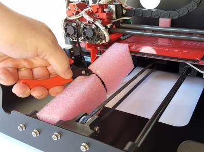
18 12. Remove the pink padding from the L/H side. FIGURE 8: REMOVING PINK PADDING FROM THE L/H SIDE Infinity3D_Unpacking_Instructions_V Copyright 2016, Revolution 3D Printers
,")
.")


19 13. Using diagonal cutters (not included), cut all tie-wraps that have tails (5x). Do not remove foam blocks until step 22. FIGURE 9: CUT ALL TIE-WRAPS THAT HAVE TAILS Infinity3D_Unpacking_Instructions_V Copyright 2016, Revolution 3D Printers


20 14. Plug-in power cord adaptor to power supply. FIGURE 10: PLUG-IN POWER CORD ADAPTOR TO POWER SUPPLY 15. Plug-in power cord to wall outlet. 16. Turn on power supply. FIGURE 11: TURN ON POWER SUPPLY Infinity3D_Unpacking_Instructions_V Copyright 2016, Revolution 3D Printers

21 17. Turn on printer main power switch. FIGURE 12: TURN ON PRINTER MAIN POWER SWITCH 18. Wait 1 minute. Infinity3D_Unpacking_Instructions_V Copyright 2016, Revolution 3D Printers

22 19. Slide to unlock Touch interface. FIGURE 13: SLIDE TO UNLOCK TOUCH INTERFACE Infinity3D_Unpacking_Instructions_V Copyright 2016, Revolution 3D Printers
23 20. CONTROLS screen will open, MOVEMENT tab will be open. Select 10mm FIGURE 14: CONTROLS SCREEN AND MOVEMENT TAB Infinity3D_Unpacking_Instructions_V Copyright 2016, Revolution 3D Printers

24 21. Click Z+ four times to raise Z axis 40mm FIGURE 15: MOVEMENT TAB Z+ BUTTON Infinity3D_Unpacking_Instructions_V Copyright 2016, Revolution 3D Printers


25 22. Remove the L/H Z-axis foam block. FIGURE 16: REMOVE THE L/H Z-AXIS FOAM BLOCK Infinity3D_Unpacking_Instructions_V Copyright 2016, Revolution 3D Printers

26 23. Remove the shipping block. FIGURE 17: REMOVE THE SHIPPING BLOCK Infinity3D_Unpacking_Instructions_V Copyright 2016, Revolution 3D Printers


27 24. Move the extruder assembly manually to the center of the Quick-change build platform. Remove the small foam block that was between the extruder assembly and motor mount. FIGURE 18: REMOVE THE SMALL FOAM BLOCK BETWEEN EXTRUDER ASSEMBLY AND MOTOR MOUNT Infinity3D_Unpacking_Instructions_V Copyright 2016, Revolution 3D Printers

28 25. Remove the Quick-change Build Platform foam block from the front. FIGURE 19: REMOVE QUICK-CHANGE BUILD PLATFORM FOAM BLOCK FROM THE FRONT Infinity3D_Unpacking_Instructions_V Copyright 2016, Revolution 3D Printers


29 26. Manually move the Quick-change build platform forward. Remove the Quick-change Build Platform foam block from the back. FIGURE 20: REMOVE QUICK-CHANGE BUILD PLATFORM FOAM BLOCK FROM THE BACK Infinity3D_Unpacking_Instructions_V Copyright 2016, Revolution 3D Printers

30 27. Remove the R/H Z-axis foam block. FIGURE 21: REMOVE THE R/H Z-AXIS FOAM BLOCK Infinity3D_Unpacking_Instructions_V Copyright 2016, Revolution 3D Printers

31 28. Install the Quick Change Build Platform and ensure it is on squarely. FIGURE 22: INSTALL THE QUICK-CHANGE BUILD PLATFORM Infinity3D_Unpacking_Instructions_V Copyright 2016, Revolution 3D Printers

32 29. Install the filament spool holder stand and top with the flat facing forward. The spool holder stand is a 3D printed part which supports the filament spools during the print. The following steps describe how to install the spool holder stand and top. The final assembly is shown below: Infinity3D_Unpacking_Instructions_V Copyright 2016, Revolution 3D Printers

33 FIGURE 23: INSTALLING SPOOL HOLDER TOP The is now set up and ready for Operation. Refer to the Operations & Maintenance Manual for Filament Loading instructions and Touch Interface use. Infinity3D_Unpacking_Instructions_V Copyright 2016, Revolution 3D Printers
Quick Start Guide. Caution. Warning. This guide only applies to Dreamer 3D printer of Flashforge
 Quick Start Guide Caution Warning. Do not peel the yellow film from the build plate. It is heat-resistant tape, which makes objects stick to the build plate easily.. Do not remove the wrapping around the
3D PRINTER USER MANUAL
 3D PRINTER USER MANUAL Table of contents page: 1. Introduction 2. Table of contents 3. Basic informations 4. General information 5. Glossary 6. Starter pack s content 7. Technical parameters 8. Device
WANHAO Duplicator i3. User Manual V1.2. Wanhao USA
 WANHAO Duplicator i3 User Manual V1.2 Wanhao USA 2015 www.wanhaousa.com Safety WARNING: The components on the Duplicator i3 generate high temperatures and move extremely fast. Reaching inside of the Duplicator
Installation and service instructions, warranty terms & conditions. DeeGreen. User Guide. Version 2.6
 Installation and service instructions, warranty terms & conditions DeeGreen User Guide Version 2.6 - 2 - Contents 1. Contents...- 3-2. Technical parameters...- 4-3. Safety instructions...- 4-4. Package
Model 700 Microarray Oven
 www.scigene.com Model 700 Microarray Oven USER MANUAL Cat. #1070-00-1, 1070-00-2 FOR RESEARCH USE ONLY Not for Use in Diagnostic Procedures SciGene 306 Potrero Ave, Sunnyvale, CA 94085 USA 408-733-7337
JGAURORA 3D PRINTER MODEL: A5 USER GUIDE
 JGAURORA 3D PRINTER MODEL: A5 USER GUIDE Contents ----3D Printer User Guide 1. Preface... 2 1.1 Introduction...2 1.2 Safety advice... 2 1.3 Filament requirements...2 1.4 Environmental requirements...2
FlexChem Model 404 Rotating Oven
 www.scigene.com FlexChem Model 404 Rotating Oven USER MANUAL Cat. #1052-20-1, 1052-20-2, 1052-22-1 & 1052-22-2 FOR RESEARCH USE ONLY Not for Use in Diagnostic Procedures SciGene 306 Potrero Ave, Sunnyvale,
Starter Kit Identification. Included in your ProJet 1500 Starter Kit are all the supplies you will need to start your first print.
 To access the Online ProJet User s Guide. Please enter http://3dpedia.3dsystems.com. Enter the assigned User Name:pj15k and Password: pj15k and click Login. Please read all safety precautions before operating
MP Maker Pro Mk.1 P/N User's Manual
 MP Maker Pro Mk.1 P/N 33013 User's Manual CONTENTS SAFETY WARNINGS AND GUIDELINES... 3 INTRODUCTION... 5 FEATURES... 5 CUSTOMER SERVICE... 5 PACKAGE CONTENTS... 6 PRODUCT OVERVIEW... 7 Front View... 7
create Model Number: HE INSTRUCTION MANUAL
 create Model Number: HE150277 INSTRUCTION MANUAL . Important Getting the most out of your 3D Pen: Read the manual carefully It will help you get set up with ease Visit www.cocooncreate.com.au We ve got
To be the Chief Evangelist CR-10S Pro Printer Guide Book To make Top-quality 3D printer
 To be the Chief Evangelist CR-0S Pro Printer Guide Book To make Top-quality 3D printer This guide book is for standard CR-0S Pro. Please plug the power cord into a three-hole power jack. Detailed instructions
TeeBox. The Suitcase 3D printer. BY:
 TeeBox The Suitcase 3D printer. BY: Eindhoven The Netherlands Contents Liability... 2 Returns... 2 WARNING... Error! Bookmark not defined. TRICKS AND TIP... 4 PART 1 ---Y AXIS (PRINT BED)... 7 Fasten heatbed
PLEASE READ THESE INSTRUCTIONS CAREFULLY, BEFORE YOU START INSTALLATION
 PART NUMBER: L0SSJ000 INSTALLATION INSTRUCTIONS DESCRIPTION: FORESTER TRAILER HITCH PLEASE READ THESE INSTRUCTIONS CAREFULLY, BEFORE YOU START INSTALLATION SAFETY PRECAUTION: When installing Trailer Hitch,
Daily T-Jet2 TM Maintenance Procedures January 2007 Ver1.1
 Daily T-Jet2 TM Maintenance Procedures January 2007 Ver1.1 As a T-Jet2 owner there is daily maintenance that will need to be performed to ensure proper operation of your printer. By not following the required
Delta Rostock mini G2S Pro 3D Printer
 Delta Rostock mini G2S Pro 3D Printer Copyright Declaration The copyright of this manual belongs to the Shenzhen GETECH CO., LTD. (hereinafter referred to as the "Geeetech"), and all rights reserved. No
INSTALLATION INSTRUCTIONS
 TABLE OF CONTENTS GENERAL...2 SPECIFICATIONS...2 PACKAGE CONTENTS...2 PACKAGE CONTENTS: ACCESSORIES...3 REQUIRED TOOLS...3 ADD-ON COMPONENTS...3 CLOSURE MOUNTING...3 LOCK AND UNLOCK EXTERIOR DOOR...3 CABLE
OPERATION AND MAINTENANCE
 Table of Contents GENERAL INFORMATION INTRODUCTION... 1 Operating Specifications... 1 FEATURES... 1 SAFETY PRECAUTIONS... 2 SET-UP... 2 OPERATION AND MAINTENANCE TESTING AN IGNITION MODULE OR IGNITION
5. E-axis assembly. 5. E-axis assembly. Written By: Jakub Dolezal manual.prusa3d.com/ Page 1 of 40
 5. E-axis assembly Written By: Jakub Dolezal 2018 manual.prusa3d.com/ Page 1 of 40 Step 1 Tools necessary for this chapter Needle-nose pliers for zip tie trimming. 2.5mm Allen key for M3 screws 2mm Allen
UM3 Spare Parts Ultimaker 3 Spare-Parts Version /06/18
 Ultimaker 3 Spare-Parts Version 1.2 13/06/18 Housing 1156 Z-Shaft Cap Bottom 1901 Controler Electronics Cover 1902 Main Board Electronics Cover 1903 Cable Cover 1904 Wifi Cover 1905 Print Table Back Cover
Heated Bed Installation Instructions
 Heated Bed Installation Instructions Overview The glass panel is heated by way of a heater element which is bonded to the glass panel and controlled by a digital temperature controller. The temperature
6. Pre-print checks. 3D Touch
 Page 1 1. 6. Pre-print checks........................................................................................... 1.1 a. Clearing the print bed..................................................................................
Introduction to 3D Printing
 TAKE HOME LABS OKLAHOMA STATE UNIVERSITY Introduction to 3D Printing by Sean Hendrix 1 OBJECTIVE The objective of this experiment is to introduce you to 3D printing, by having you print some simple parts
1200W Paint DRYING Lamp
 1200W Paint DRYING Lamp Model 97641 Assembly And Operation Instructions Diagrams within this manual may not be drawn proportionally. Due to continuing improvements, actual product may differ slightly from
Universal Splice Tray Installation Instructions
 Universal Splice Tray Installation Instructions Table of Contents General Product Information... 1.0 Safety Precautions... 2.0 Package Contents... 3.0 Installing the Product... 4.0 Tower Mounting... 5.0
TOYOTA im NAVIGATION UPGRADE Preparation
 Preparation Part Number: PT296-00170 PT296-12170 (Extension Module w/ AHA) Kit Contents Item # Quantity Reqd. Description 1 1 Extension Module 2 1 BT cable 3 1 DA/Ext Harness 4 1 GPS Antenna kit 5 6 Bolt
PLEASE READ THIS INSTRUCTIONS CAREFULLY, BEFORE YOU START INSTALLATION
 INSTALLATION INSTRUCTIONS PART NUMBER: L0SXC000 DESCRIPTION: 09 ASCENT TRAILER HITCH PLEASE READ THIS INSTRUCTIONS CAREFULLY, BEFORE YOU START INSTALLATION SAFETY PRECAUTION: When installing Trailer Hitch,
Trus-T-Lift 750 Owners Operation Manual. Copyright 2016
 Trus-T-Lift 750 Owners Operation Manual Copyright 2016 Revision A Aug 15, 2016 Section 1: Contents Section 1: Introduction... 2 Section 2: Safety and Warnings... 2 Section 3: Operating Instructions...
2-1/4 Gallon Sprayer
 2-/4 Gallon Sprayer 94008 ASSEMBLY AND OPERATING INSTRUCTIONS 349 Mission Oaks Blvd., Camarillo, CA 930 Visit our Web site at http://www.harborfreight.com Copyright 2005 by Harbor Freight Tools. All rights
PART NUMBER: H630SXC001. Kit Contents: A. Amplifier with Bracket (1) D. Badge (2) with push nuts (4)
 D. Badge (2) with push nuts (4)") Kit Contents: A. Amplifier with Bracket (1) D. Badge (2) with push nuts (4) E. Clip B. Interface / Power Harness (1) C. Cable tie (8) F. Mounting Nuts (2) G. Replacement Front Speaker (2) H. Badge mounting
Kit Contents: A. Amplifier with Bracket (1) D. Badge (2) with push nuts (4) E. Clip B. Interface / Power Harness (1) C. Cable tie (8) F. Mounting Nuts (2) G. Replacement Front Speaker (2) H. Badge mounting
OWNER'S MANUAL. Royal Sovereign International Inc. RET Desk Series
 OWNER'S MANUAL RET Desk Series Read all instructions carefully before use. For any Customer Support needs please choose the Customer Support tab on www.royalsovereign.com Royal Sovereign International
SCION im PREMIUM AUDIO Preparation
 SCION im 2016 - PREMIUM AU Preparation Part Number: PT296-12160 (Extension Module w/ AHA) Kit Contents Item # Quantity Reqd. Description 1 1 Extension Module 2 1 BT cable 3 1 DA/Ext Harness 4 1 GPS Antenna
Artisan Technology Group is your source for quality new and certified-used/pre-owned equipment
 Artisan Technology Group is your source for quality new and certified-used/pre-owned equipment FAST SHIPPING AND DELIVERY TENS OF THOUSANDS OF IN-STOCK ITEMS EQUIPMENT DEMOS HUNDREDS OF MANUFACTURERS SUPPORTED
EVOS M5000 Imaging System
 EVOS M5000 Imaging System Pub. No. MAN0017783 Doc. Part No. 710208 Rev. A.0 Note: For safety and biohazard guidelines, see the Safety appendix in the EVOS M5000 Imaging System User Guide (Pub. No. MAN0017563).
PUSH BUTTON KEY CABINET
 PUSH BUTTON KEY CABINET Model 95689 INSTALLATION And Operation Instructions Due to continuing improvements, actual product may differ slightly from the product described herein. 3491 Mission Oaks Blvd.,
FEATURES. Power Status and Charge Indicator: A red LED indicates the battery is charging and a green LED indicates the battery is fully charged.
 7-in-1 Power Station Model: 52036 DO NOT RETURN TO STORE. Please CALL 800-348-5004 for parts and service. CALIFORNIA PROPOSITION 65 WARNING: You can create dust when you cut, sand, drill or grind materials
Please visit for the latest version of these installation instructions.
 Please visit www.blueox.com for the latest version of these installation instructions. Please read BOTH these and the General Information sheet prior to installing or operating this equipment. 1. Blue
PLANER 400W INSTRUCTION MANUAL SPECIFICATIONS. ozito.com.au WHAT S IN THE BOX. Planer. Guide Fence. Spanner. Input Power: Planing Width:
 WHAT S IN THE BOX PLANER 400W INSTRUCTION MANUAL SPECIFICATIONS Input Power: No Load Speed: Planing Width: Blade Type: Planing Depth: Rebate Depth: Weight: ozito.com.au 400W 16,000 / min 82mm HSS Blades
CHAPTER 5 CORDLESS GENERAL CORDLESS COMPONENTS
 CHAPTER 5 CORDLESS CHAPTER 5 CORDLESS GENERAL The Cordless aligner offers the users the capability to perform all alignment functions without the use of cables leading from the wheel sensors to the console.
Prusa i3 Printer Assembly Guide
 Prusa i3 Printer Assembly Guide Special thanks to Carlos Sanchez and Miguel Sanchez for the graphics. All graphics captured from their great animation: http://www.carlos-sanchez.com/ Prusa3/ For copyright
Geeetech Prusa I3 M201
 Geeetech Prusa I3 M20 Copyright Declaration The copyright of this manual belongs to the Shenzhen GETECH CO., LTD. (hereinafter referred to as the "Geeetech"), and all rights reserved. No part of this specification
2. Multiplexer assembly
 2. Multiplexer assembly Written By: Jakub Dolezal 2017 manual.prusa3d.com/ Page 1 of 15 Step 1 Parts identification Y-splitter (new version) - QSM fittings and steel tubes are assembled in the factory.
CORDLESS GLUE GUN. 7.2V Lithium Ion INSTRUCTION MANUAL SPECIFICATIONS. ozito.com.au GGL-7000 WHAT S IN THE BOX. Cordless Glue Gun.
 WHAT S IN THE BOX CORDLESS GLUE GUN 7.2V Lithium Ion INSTRUCTION MANUAL SPECIFICATIONS Input: 7.2V Glue Stick Diameter: 7.2mm Glue Stick Length: 190mm Heating Time: 15sec Working Time: 45min Battery Power:
TRIPODMAKER BLACK EDITION USER MANUAL
 TRIPODMAKER BLACK EDITION USER MANUAL TABLE OF CONTENT Specifications and box content 1. Specifications of the Tripodmaker...4 2. Box content...5 3. Terminology...6 4. Attentions and warnings...8 Unboxing
Geeetech Prusa I3 M201. Assembly Manual
 Geeetech Prusa I3 M20 Assembly Manual SUPPORT Thanks for choosing Geeetech, we strive to provide a satisfied and pleasant shopping experience for you, but we do understand there may be some questions you
Installation and Service Manual
 RESIDENTIAL PLATFORM LIFTS RPL400 / RPL600 Installation and Service Manual WARNING! STRICT ADHERENCE TO THESE INSTALLATION INSTRUCTIONS IS REQUIRED to promote the safety of those installing this product,
Copyright Declaration
 Geeetech Prusa I3 X Copyright Declaration The copyright of this manual belongs to the Shenzhen GETECH CO., LTD. (hereinafter referred to as the "Geeetech"), and all rights reserved. No part of this specification
EFX Integrated LCD Screen Option. Cardio Theater Integrated Bracket Assembly Instructions
 EFX Integrated LCD Screen Option Cardio Theater Integrated Bracket Assembly Instructions Table of Contents 1 2 3 4 5 6 7 Before You Begin... 4 Obtaining Service... 4 Unpacking the Equipment... 4 Important
TL4076 Top 5 Tips Get to know your TL4076
 TL4076 Top 5 Tips Get to know your TL4076 Thermal Break with Teflon liner (behind fan) Hot End Assembly Fan Heat Block Extruder with toothed gear(brass) and idler (steel) Filament Guide Tube Nozzle Cable
Quick Start Guide INVENTOR II SZ15-EN-A02
 Quick Start Guide INVENTOR II SZ15-EN-A02 WARNING 1. Hot! Avoid touching the heating nozzle in operation. 2. Moving parts in printer may cause injury. Do not wear gloves or other sources of entanglement
14.4 CORDLESS DRILL ASSEMBLY AND OPERATING INSTRUCTIONS
 14.4 CORDLESS DRILL 40209 ASSEMBLY AND OPERATING INSTRUCTIONS 3491 Mission Oaks Blvd., Camarillo, CA 93011 Visit our Web site at http://www.harborfreight.com Copyright 2002 by Harbor Freight Tools. All
GENUINE PARTS INSTALLATION INSTRUCTIONS
 GENUINE PARTS INSTALLATION INSTRUCTIONS 1. 2. 3. 4. DESCRIPTION: APPLICATION: PART NUMBER: KIT CONTENTS: Accent light Kit Pathfinder 999F3 XZ000 - Accent Lighting Kit. Item QTY Description Service Part
Building Instruction of Geeetech Prusa I3 pro W. 3D Printer
 Building Instruction of Geeetech Prusa I3 pro W 3D Printer Version 05-31-2017 Contents Safety Instructions... 2 Preparations... 3 1.Unfold the box and check the package... 4 2 Assemble the rods of a Y
Rechargeable Inflator
 See Warranty on page 6 for important information about commercial use of this product. Operating Instructions and Parts Manual HDC230 Please read and save these instructions. Read carefully before attempting
INSTALLATION INSTRUCTIONS
 INSTALLATION INSTRUCTIONS Accessory S P/N 08V67-SJC-101 Application 2010 RIDGELINE Publications No. AII 42117 Issue Date AUG 2009 PARTS LIST Back-up sensor harness 3 Wire ties with small clip (2 Not used)
FiberSource Q150. user manual P/N
 FiberSource Q150 user manual P/N 510260 1997, 1998 Martin Professional A/S, Denmark. All rights reserved. No part of this manual may be reproduced, in any form or by any means, without permission in writing
INSTALLATION INSTRUCTIONS
 INSTALLATION INSTRUCTIONS Accessory Application Publications No. SYSTEM 2005 ACCORD All 27511 (DX, LX) 2-AND 4-DOOR Issue Date AUG 2004 PARTS LIST Security System Attachment (LX): P/N 08E55-SDA-100A Unit
Technical Service BULLETIN
 Technical Service BULLETIN August 21, 2006 Title: Models: 03 07 4Runner BO016-06 BODY TSB REVISION NOTICE: August 25, 2006: The Warranty Information table has been updated to include warranty. Previous
Building Instructions of Geeetech Prusa I3 M201
 Building Instructions of Geeetech Prusa I3 M201 (Version 11-25-2016) CONTENT Safety Instructions... 1 Preparation... 2 1. Assemble the threaded rods of Y axis... 3 2. Assemble the front and back support
5. Extruder Assembly
 5. Extruder Assembly Guide for the assembly of the Extruder. Written By: Josef Prusa 2018 manual.prusa3d.com/ Page 1 of 24 Step 1 Get the necessary tools 2.5 and 1.5 mm Allen key Needle-nose pliers 2018
Assembly Instructions of Geeetech Prusa I3 A pro
 Assembly Instructions of Geeetech Prusa I3 A pro (Version 04-11-2016) CONTENT Safety Instructions... 3 Preparation... 4 1. Unfold the box and check the package... 1 2. Assemble Y axis... 1 3. Build the
Written By: Josef Prusa
 7. PSU & Heatbed assembly PSU and Heatbed guide Written By: Josef Prusa 2017 manual.prusa3d.com/ Page 1 of 17 Step 1 Getting the necessary tools 2 and 2.5 mm allen key Needle-nose pliers Step 2 3D printed
INSTALLATION INSTRUCTIONS
 INSTALLATION INSTRUCTIONS Accessory S Application 2013 ACCORD 4-DOOR Publications No. AII 13026 Issue Date AUG 2012 PARTS LIST Aluminum tape Backup Sensors Attachment Kit P/N 08V67-T2A-100A Control unit
Service Bulletin No.: DA C , Rev.0 Date Issued: October 8, 1998 Title: Type II Fuel System/Pump Retrofit Page: 1 of 13
 Title: Type II Fuel System/Pump Retrofit Page: 1 of 13 1. ATA Code: 2810 PLANNING INFORMATION: 2. Effectivity: DA20-C1 aircraft with Type I fuel systems S/N C0002 - C0013. DA20-C1 aircraft with Facet fuel
PART NUMBER: H630SSJ000. Kit Contents: A. Amplifier with Bracket (1) D. Badge (2) with push nuts (4)
 D. Badge (2) with push nuts (4)") Kit Contents: A. Amplifier with Bracket (1) D. Badge (2) with push nuts (4) E. Clip B. Harness (1) C. Cable tie (8) F. Mounting Hardware (2) G. Replacement Speaker (2) H. HVAC Duct extension (2) IMPORTANT:
Kit Contents: A. Amplifier with Bracket (1) D. Badge (2) with push nuts (4) E. Clip B. Harness (1) C. Cable tie (8) F. Mounting Hardware (2) G. Replacement Speaker (2) H. HVAC Duct extension (2) IMPORTANT:
EVO TM 200 AND EVO TM 400 LCD DISPLAY INSTALLATION GUIDE
 EVO TM 200 AND EVO TM 400 LCD DISPLAY INSTALLATION GUIDE The information in this publication is provided for reference only. While every effort has been made to ensure the reliability and accuracy of the
Pellicon 2 and 3 Mini Holder. User Guide
 Pellicon 2 and 3 Mini Holder User Guide Notice The information in this document is subject to change without notice and should not be construed as a commitment by Millipore Corporation. Millipore Corporation
Witbox 2. Quick start guide
 Witbox 2 Quick start guide Welcome. Thank you for choosing us. This manual will help you to use your new 3D printer correctly. Welcome to the world of Witbox 2. How do I use this manual? To make sure that
INSTRUCTION MANUAL VERSION 1 ISSUED 23/11/17 MODEL NUMBER: HE161192
 INSTRUCTION MANUAL VERSION 1 ISSUED 23/11/17 MODEL NUMBER: HE161192 IMPORTANT Getting the most out of your 3D Printer Touch: Read the manual carefully It will help you set up with ease Visit wwwcocoonproductscomau
CORDLESS BLOWER. 36V Lithium Ion INSTRUCTION MANUAL SPECIFICATIONS. ozito.com.au BLL- 036 WHAT S IN THE BOX. Blower. Blower Tube.
 WHAT S IN THE BOX CORDLESS BLOWER 36V Lithium Ion INSTRUCTION MANUAL SPECIFICATIONS Voltage: 36V Battery: 3.0Ah Li-ion Charge Time: 3 Hours No Load Speed: 10,000-16,000/min Max. Air Speed: 252km/hr Weight
CONTENT. User manual. Building the 3Dsimo KIT. First start. Filament usage and filament change
 MANUAL CONTENT User manual Building the 3Dsimo KIT First start Filament usage and filament change 4 6 18 22 USER MANUAL ٱٱ ٱٱ ٱٱ ٱٱ ٱٱ ٱٱ You have obtained multimaterial building kit, the 3Dsimo KIT.
RENA AF371Feeder Operating Manual. Feeder. Operating Manual. Manual Part #: M AF371 Operations Rev
 Manual Part #: M-3022 Feeder AF371 Operations Rev. 3-16-04 1 RENA AF371 Feeder YOUR RENA AF371 IS DISTRIBUTED BY RENA SYSTEMS INC. SERVICE AND SUPPORT FOR THIS PRODUCT IS PROVIDED BY YOUR RENA DEALER.
TWIN HALOGEN SHOP LIGHT
 TWIN HALOGEN SHOP LIGHT 36787 ASSEMBLY & OPERATING INSTRUCTIONS 3491 Mission Oaks Blvd., Camarillo, CA 93011 Visit our Web Site at www.harborfreight.com Copyright 2005 by Harbor Freight Tools. All rights
8. Electronics assembly (B3/R2 design)
") 8. Electronics assembly (B3/R2 design) Written By: Jakub Dolezal 2018 manual.prusa3d.com/ Page 1 of 31 Step 1 Tools necessary for this chapter Needle-nose pliers for zip tie trimming. 2.5mm Allen key for
8. Electronics assembly (B3/R2 design) Written By: Jakub Dolezal 2018 manual.prusa3d.com/ Page 1 of 31 Step 1 Tools necessary for this chapter Needle-nose pliers for zip tie trimming. 2.5mm Allen key for
User s Guide. Oreck Air Purifier with HEPA Filtration. Important! Read this manual carefully, and keep for future reference.
 User s Guide Oreck Air Purifier with HEPA Filtration Important! Read this manual carefully, and keep for future reference. Enjoy Congratulations on your purchase of the Oreck Air Purifier with HEPA Filtration.
SUBMERSIBLE POND PUMP
 SUBMERSIBLE POND PUMP 258 Gallons Per hour 47117 ASSEMBLY AND OPERATING INSTRUCTIONS 3491 Mission Oaks Blvd., Camarillo, CA 93011 Visit our Web site at http://www.harborfreight.com Copyright 2002 by Harbor
DISC BRAKE CALIPER TOOL SET
 DISC BRAKE CALIPER TOOL SET 40732 ASSEMBLY AND OPERATING INSTRUCTIONS Diagrams within this manual may not be drawn proportionally. Due to continuing improvements, actual product may differ slightly from
Operating Manual. D3D Innovations Limited. 7 Kings Road, Wrington, Bristol, BS40 5LW, UK.
 Operating Manual FILAMENT WINDER D3D Innovations Limited 7 Kings Road, Wrington, Bristol, BS40 5LW, UK www.filafab.co.uk www.d3dinnovations.com www.filafab.co.uk Copyright 2016 by D3D Innovations Limited
Filabot Original and Filabot EX2. Operation Manual
 Triex LLC Barre, Vermont 05641 USA 1 802 505 6772 Filabot Original and Filabot EX2 Operation Manual This manual applies to the Filabot Original and Filabot EX2 by Triex LLC. Triex LLC, Barre, VT 05641,
BX Dodge Nitro Jeep Liberty Limited 4x4 Installation Instructions
 1. Blue Ox towing products and accessories are intended to be installed by Blue Ox Dealers who are familiar with our products and have the equipment and knowledge to do fit work. When necessary Blue Ox
Go Power! Manual. GP-Smart Charger
 Go Power! Manual GP-Smart Charger Go Power! Electric Inc. PO Box 6033 Victoria, BC V8P 5L4 Toll Free Tel: 866-247-6527 Toll Free Fax: 866-607-6527 Email: info@gpelectric.com Table of Contents 1. IMPORTANT
TOYOTA VENZA 2009 TRAILER WIRE HARNESS Procedure
 Part Number: PT791-0T099 Kit Contents Item # Quantity Reqd. Description 1 1 Trailer Wire Harness Module 2 1 4-Flat Harness 3 1 Battery Power Wire Harness 4 1 Mounting Bracket, 4-Flat 5 2 Screw #10-24 6
P. D. Q. Automatic Burnout Furnaces. 115 and 230-volt Models OPERATOR S MANUAL
 P. D. Q. Automatic Burnout Furnaces 115 and 230-volt Models OPERATOR S MANUAL TABLE OF CONTENTS Introduction... 3 Warranty... 3 Safety Instructions........................................................
Plastic Tube Flar ing Syste m
 www.swagelok.com Plastic Tube Flar ing Syste m Model F TF 1000 Safety Instructions.......................... 2 General Information......................... 2 Setup Tubing Selection and Preparation..............
INSTALLATION INSTRUCTIONS
 INSTALLATION INSTRUCTIONS Accessory REMOTE ENGINE STARTER SYSTEM Application 2010 CIVIC 4-DOOR Publications No. AII 42460 Issue Date AUG 2009 PARTS LIST Remote Engine Starter Unit Kit P/N 08E91-E22-100B
ELECTRIC LONG SHAFT DIE GRINDER 44141
 ELECTRIC LONG SHAFT DIE GRINDER 44141 ASSEMBLY and OPERATING INSTRUCTIONS 1/4 Collet Accepts Most Popular Die Grinding Accessories Diagrams within this manual may not be drawn proportionally. Due to continuing
PRELIMINARY INSTALLATION INSTRUCTIONS. Remote Engine Starter Attachment Kit P/N 08E92-SNA-100B
 INSTALLATION INSTRUCTIONS Accessory Application Publications No. REMOTE ENGINE STARTER SYSTEM 2008 CIVIC 2-DOOR AII 38215 Issue Date OCT 2007 PARTS LIST Remote Engine Starter Unit Kit P/N 08E91-E22-100B
Service Bulletin No.: DAC Date Issued: February 18, 2000 Title: Starting Vibrator Battery Installation Page: 1 of 6
 Title: Starting Vibrator Battery Installation Page: 1 of 6 1. ATA Code: 7410 2. Effectivity: DA20-C1 s/n C0001 up to and including C0102. 3. General: This service bulletin addresses the installation of
Power Paint Scraper 200W CPS-200. To view the full range visit: Instruction Manual 3 Year Replacement Warranty
 Power Paint Scraper 200W Instruction Manual 3 Year Replacement Warranty CPS-200 WARNING! Read all safety warnings and all instructions Failure to follow the warnings and instructions may result in electric
ATD Gallon Pressurized Oil Drain Owner s Manual
 ATD-5203 30 Gallon Pressurized Oil Drain Owner s Manual TECHNICAL SPECIFICATIONS Model: ATD-5203 Capacity: 30 Gallon Drain Funnel Working Height: 47.25 to 70.5 Drain Funnel Diameter: 15.75 Plastic Tray:
DESIGNER SERIES HINGED GLASS PANEL, GRILLE, BLIND AND SHADE INSTRUCTIONS
 2016 Pella Corporation Part Number: 80ML0106 INSTRUCTION INSTRUCCIONES DE INSTALACIÓN DESIGNER SERIES HINGED GLASS PANEL, GRILLE, BLIND AND SHADE INSTRUCTIONS CAUTION: DO NOT remove or cut the white cord
GENUINE Interior Lighting Kit
 GENUINE Interior Lighting Kit INSTALLATION INSTRUCTIONS Thank you for purchasing a genuine Mazda accessory. Before removal and installation, be sure to thoroughly read these instructions. Please read the
Broadband PowerShield. External Battery Pack 20 Ah 12 V Battery. User Manual
 Broadband PowerShield External Battery Pack 20 Ah 12 V Battery User Manual 990-1660 08/2003 Chapter 1 General Information The APC PowerShield External Battery Pack connects directly to the APC PowerShield
INSTALLATION INSTRUCTIONS
 INSTALLATION INSTRUCTIONS Accessory S P/N 08V67-SJC-101 Application 2012 RIDGELINE Publications No. AII 12006 Issue Date NOV 2011 PARTS LIST Back-up sensor harness 3 Wire ties with small clips (2 Not used)
Special Chemicals VDC approved cleaner. General Applicability All Scion iq models, including 10 Year Anniversary Edition.
 Preparation Part Number: PT296-00140 or PT296-00142 (Extension Box w/aha) Kit Contents Item # Quantity Req. Description 1 1 Extension Module w/bt cable 2 1 DA/Ext Harness 3 1 GPS Antenna kit 4 4 Screws
Installation Instruction of CTC DIY 3D Printer
 Installation Instruction of CTC DIY 3D Printer Focus on high-end science and technology,focus on 3D printing Zhuhai CTC Electronics Co.,Ltd. www.ctcprinter.com 1 Introduction This DIY 3D printer can be
nual k Voltage Stabilizer N) manual New Brunswick Voltage Stabilizer Operating manual
 manual New Brunswick Voltage Stabilizer Operating manual") nual k Voltage Stabilizer N) manual New Brunswick Voltage Stabilizer Operating manual Copyright Copyright 2014 Eppendorf AG, Germany. No part of this publication may be reproduced without the prior permission
nual k Voltage Stabilizer N) manual New Brunswick Voltage Stabilizer Operating manual Copyright Copyright 2014 Eppendorf AG, Germany. No part of this publication may be reproduced without the prior permission
ELECTRIC ENGRAVER 15W WARRANTY INSTRUCTION MANUAL SPECIFICATIONS WHAT S IN THE BOX. ozito.com.au. Electric Engraver
 IN ORDER TO MAKE A CLAIM UNDER THIS WARRANTY YOU MUST RETURN THE PRODUCT TO YOUR NEAREST BUNNINGS WAREHOUSE WITH YOUR BUNNINGS REGISTER RECEIPT. PRIOR TO RETURNING YOUR PRODUCT FOR WARRANTY PLEASE TELEPHONE
Model Year: 2008 Model: xb Doc ID: RM000001XUW004X
 1 of 18 2/28/2008 10:41 AM Last Modified: 2-12-2007 Service Category: Vehicle Interior 1.6 A Section: Interior Panels/Trim Model Year: 2008 Model: xb Doc ID: RM000001XUW004X Title: INTERIOR: ROOF HEADLINING:
360 LINE LASER LEVEL. 20m Working Range WARRANTY INSTRUCTION MANUAL SPECIFICATIONS. ozito.com.au LLT-3605 WHAT S IN THE BOX
 WHAT S IN THE BOX 360 LINE LASER LEVEL 20m Working Range INSTRUCTION MANUAL SPECIFICATIONS Battery: Laser Power: Working Range: Laser Diode: Accuracy: 6V DC (4 x AA Battery) Class 2,