Essential Loads also use stand by generator systems mostly in process industries as they relate to high restarting times or high down times.
|
|
|
- Dominick Phelps
- 5 years ago
- Views:
Transcription

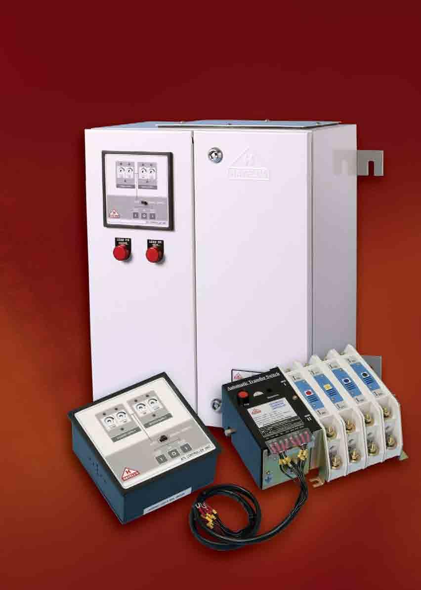
1 The need for continuous power supply and its reliability has increased rapidly over the years, especially in all those areas where uninterrupted power supply is a must. Modern systems are power dependent. Their complexity has increased as continuous information and communications are needed to control automated process, be in industries, commercial complexes, hospitals, hotels or even modern residences. The need, as such, for independent stand by power system has therefore increased manifold. The power distribution, control, monitoring and protection of stand by power system needs to be integrated. Stand by generator systems, for example, are required to cater to :- Sensitive Loads are supplied by UPS systems. The period of non-availability of power, before the stand by supply takes over, is bridged by battery banks. Typical loads are computers, hospital equipments, micro processor controlled industrial machines etc. Critical Loads mostly involve stand by generator systems which supply power to lighting systems, air conditioning, elevators etc in Airports, Hotels and commercial complexes. Essential Loads also use stand by generator systems mostly in process industries as they relate to high restarting times or high down times. Automatic transfer from main supply to stand by supply is vital for all the above kinds of loads. In the event of power failure, the stand by power is usually expected to take over automatically. Electrical starting equipment, battery bank and diesel generator are required for the automatic operation. The automatic transfer is achieved mostly by automatic mains failure systems. The process of onload transfer has to be monitored & controlled for a smooth Changeover and within safety limits of all elements of the system. This is achieved by Automatic Transfer Switch (ATS). 100 Range Current rating from 100A to 630A in three frame sizes in three pole and four pole execution. Specification Conforms to IEC: and IEC: / IS: Features High speed transfer Superior making & breaking capacity Compact & light weight design Positive indication through flag indicator Neutral point transfer Liberal terminals Phase barriers
2 101

3 CONSTRUCTION 102 The Switch comprises of upto four symmetrical poles coupled with the Main Operating Mechanism. The switching mechanism is quick make, quick break type. Load terminals are given on the Lower side but can also be provided on the upper side. Contact Mechanism The contact system is housed in a frame made of Polyester reinforced glass material. Each pole has two independent set of Moving contact assemblies for Main & standby supply and one Fixed contact assembly for the common outgoing load terminals. The Moving assemblies are mechanically operated by Cams when rotated by the Main Operating Mechanism. Moving Contacts make on to Fixed Contacts under constant pressure with backup spring. Main Contacts are made of Silver-Tungsten to ensure anti-weld characteristics. The Arc Chute plates placed in the path of contact, efficiently quench the Arc and there by enhance the life of the contacts. Main Operating Mechanism The main mechanism independently actuates two sets of Cam linkages, which in turn operate the two independent moving contact assemblies. The closing command is through a Solenoid Coil supplied with 220V AC. The operating mechanism always responds by closing on the main supply side and not on to standby supply side, when both supplies are present. The tripping coil, when energised, is used to bring the ATS to OFF / Neutral position. Closing on to the standby supply is achieved through the selective coil. The energisation of selective coil, disengages the main mechanism and prevents closing on to the main supply. The solenoid coil can then close the second set of moving contacts on to the standby supply. The moving contact mechanism of the main supply and the standby supply are inherently mechanically interlocked through a double throw arrangement, which ensures that at no point of time two supplies are paralleled. Cross Sectional View of Single Pole of ATS 1 Frame 2 Housing for Arc Chute 3 Operating Shaft for Contacts 4 Moving Contact 5 Fixed Contact 6 Main Supply - Incoming Terminals 7 Standby Supply - Incoming Terminals 8 Common outgoing - Load Terminals 1. Manual Operating Handle 2. Earthing Terminal 3. Name Plate 4. Trip Button 5. Selector (Source-II) 6. On / Off Indicators (Source I & II) 7. Main Supply Terminals 8. Arc Extinguishing Chambers 9. Auxilliary Switch (2 nos.) 10. Standby Supply Terminals 11. Control Circuit Terminal Block 12. Terminals For Load 13. Actuator For Closing Coil 14. ATS Controller Unit 15. Control Wiring 16. ATS Protection Unit (optional)
4 OPERATION (AUTOMATIC) In the event of main supply being available, the ATS can be instantaneously switched ON, by the closing coil C, through terminals A 1, A 2, from its OFF / Neutral position. If the ATS is ON at the standby supply position, then it is first tripped by the trip coil TC, through terminals BT 1 - BT 2. This ensures that the two sources of supply are not paralleled. A suitable external control circuit will ensure this, as shown in circuit diagram for Automatic Instantaneous Changeover mode. The Auxiliary Switches AX or BX, disconnect the closing coil C, once the ATS is ON, thereby the power consumption of the coil C is zero, when the ATS is closed. To switch the ATS to standby supply, the selective coil SC is first energised. Then the closing coil C is powered through limit swtiches LS and terminals B 1, B 2. The Trip Coil TC, can be energised through AT 1 - AT 2 or BT 1 - BT 2 to switch off the main supply or standby supply. 103 OPERATION (IN EMERGENCY) In an emergency, the ATS can be operated manually, but as an off-load switch only. Close on to Main Supply A manual handle rotates the operating shaft by about 45 o in anticlockwise direction, to achieve closure, under off-load conditions. Close on to Standby Supply Closure on to standby supply side is achieved, when the selective mode is continously pressed and the manual handle rotates the operating shaft by about 45 o in anticlockwise direction. Trip Tripping can be achieved manually by pressing momentarily through the Trip Button.

 A 1000 1600 2000 3150 4000 6300 Rated breaking capacity at 440V (Cosφ = 0.")
 50,000 50,000 40,000 40,000 30,000 30,000 Elect. Life (No. of ops.) 15,000 15,000 12,000 12,000 10,000 10,000 Switching frequency (ops.")
5 TECHNICAL INFORMATION 104 Frame Size TNFO1 TNFO2 TNFO3 Rated Operational Current le A No. of Poles 3P / 4P 3P / 4P 3P / 4P 3P/4P 3P / 4P 3P / 4P Rated Insulation Voltage Ui V Rated Operational Voltage Ue V 440V AC/125V DC 440V AC / 125V DC 440V AC / 125V DC Rated frequency Hz Class PC PC PC PC PC PC Utilization Category AC 31A AC 31A AC 31A AC31A AC 31A AC31A Dielectric Strength KV Rated Impulse withstand Voltage Uimp KV Rated making capacity at 440V (Cosφ = 0.80) A Rated breaking capacity at 440V (Cosφ = 0.80) A Rated short time withstand current (1 sec) KA rms Fuse protected S/C withstand current KA rms Rated Short circuit making capacity KA rms Mech. Life (No. of ops.) 50,000 50,000 40,000 40,000 30,000 30,000 Elect. Life (No. of ops.) 15,000 15,000 12,000 12,000 10,000 10,000 Switching frequency (ops. per Hr) Terminal Position Front Front Front Front Front Front Terminal Capacity - Cu (cable) mm Al (cable) mm Busbar mm x 5 x 2 40 x 8 x 2 Weight 3P Kg P Kg Mounting Vertical Vertical Vertical Vertical Vertical Vertical Coil Operating Voltage V 200 / / / / / / 220 Operating Current A Main Coil 3P / 4P 3.0 / / / / / /10.5 Trip Coil Operating Time (ms) Main Power Source Make Break Standby Power Source Make Break P - Three Pole 4 P - Four Pole

6 CIRCUIT DIAGRAMS 105


7 UTILIZATION SCOPE Auto Transfer Switch is a self-acting equipment containing the transfer switching devices and other necessary devices for monitoring supply circuits and for transferring one or more load circuits from one supply to another. The operating sequence of ATS consists of an automatic transfer of a load from the normal supply to an alternate supply in the event of a monitored supply deviation and automatically returning the load to the normal supply when quality of mains supply is restored. The transfer is with a predetermined time delay and includes an interim off position. In case of both the normal and the alternate supplies being present, the ATS shall assume the normal supply position, which is termed as preferred supply. The various utilization categories show the most popular applications of Auto Transfer Switch, as per IEC UTILIZATION SCOPE Uilization Category Nature of current Frequent Infrequent Typical applications Operations operations AC-31A AC-31B Non-inductive or slightly inductive loads AC-33A AC-33B Motor loads or mixed loads including motors, resistive loads and up to 30% Alternating Current incandescent lamp loads AC-35A AC-35B Electric discharge lamp loads AC-36A AC-36B Incandescent loads DC-31A DC-31B Resistive loads Direct Current DC-33A DC-33B Motor loads or mixed loads including motors DC-36A DC-36B Incandescent lamp load THREE POLE - BASIC UNIT 106 Current Rating (A) Cat. No. Cat. No. STANDARD MODEL WITH PRIMARY SIDE PROTECTION OPEN EXECUTION 100 ATA3OA0100SXXT ATA3OD0100SXPT 160 ATA3OA0160SXXT ATA3OD0160SXPT 200 ATA3OA0200SXXT ATA3OD0200SXPT 315 ATA3OA0315SXXT ATA3OD0315SXPT 400 ATA3OA0400SXXT ATA3OD0400SXPT 630 ATA3OA0630SXXT ATA3OD0630SXPT IN ENCLOSURE 100 ATA3EA0100SXXT ATA3ED0100SXPT 160 ATA3EA0160SXXT ATA3ED0160SXPT 200 ATA3EA0200SXXT ATA3ED0200SXPT 315 ATA3EA0315SXXT ATA3ED0315SXPT 400 ATA3EA0400SXXT ATA3ED0400SXPT 630 ATA3EA0630SXXT ATA3ED0630SXPT FOUR POLE - BASIC UNIT Current Rating (A) Cat. No. Cat. No. STANDARD WITH PRIMARY MODEL SIDE PROTECTION OPEN EXECUTION 100 ATA4OA0100SXXT ATA4OD0100SXPT 160 ATA4OA0160SXXT ATA4OD0160SXPT 200 ATA4OA0200SXXT ATA4OD0200SXPT 315 ATA4OA0315SXXT ATA4OD0315SXPT 400 ATA4OA0400SXXT ATA4OD0400SXPT 630 ATA4OA0630SXXT ATA4OD0630SXPT IN ENCLOSURE 100 ATA4EA0100SXXT ATA4ED0100SXPT 160 ATA4EA0160SXXT ATA4ED0160SXPT 200 ATA4EA0200SXXT ATA4ED0200SXPT 315 ATA4EA0315SXXT ATA4ED0315SXPT 400 ATA4EA0400SXXT ATA4ED0400SXPT 630 ATA4EA0630SXXT ATA4ED0630SXPT Note : Primary side protections include single phasing, over voltage, under voltage and phase reversal. While the trip coil operates using 220V AC available from either of the electrical sources, the protection unit requires 12 DC battery input for its functioning. The same needs to be made available from an uninterrupted source such as external battery being used for self start generator set.
8 DIMENSIONS (IN MM) - OPEN EXECUTION Frame Current No. of Over All Dimensions Switch Mounting Connection Terminals Terminal Weight Size Rating (A) Poles A B C J K L P R S T V W Y Y 1 Bolt Size P φ M8x30MM 8.3Kg 100 4P φ M8x30MM 9.3Kg P φ M8x30MM 8.7Kg 160 4P φ M8x30MM 9.7Kg P φ M8x30MM 10.5Kg 200 4P φ M8x30MM 11.5Kg P φ M8x30MM 11.0Kg 315 4P φ M8x30MM 12.0Kg P φ M10x40MM 19.5Kg 400 4P φ M10x40MM 21.0Kg P φ M10x40MM 21.0Kg 630 4P φ M10x40MM 22.5Kg 107 DIMENSIONS (IN MM) - IN ENCLOSURE Indicators for Mains / Standby Cutout for Controller Cutout for Protection Unit (Optional) Note : Enclosure Sheet thickness 1.6mm (16 SWG) Cover sheet thickness 2.0 mm (14 SWG) Rating A B C D E F G H 100A-315A φ A-630A φ
The need for continuous power supply and its reliability has increased rapidly over the years, especially in all those areas where uninterrupted
 110 The need for continuous power supply and its reliability has increased rapidly over the years, especially in all those areas where uninterrupted power supply is a must. Modern systems are power dependent.
OSS - TN, TBN Type. Information to Order. Features. External View ATS(60~600A) OSS P- A B C D. Rated Current. D Operating Voltage
 OSS P- A B C D. Rated Current. D Operating Voltage") Information to Order A Rated Current 06 1 60A 100A 2 4 400A 6 600A B Type TN : TN-Type TBN : TBN-Type C Number of Poles 2 : 2P 3 : 3P 4 : 4P OSS - 6 - - P- A B C D D Operating Voltage A1 : AC 110V A2 :
Information to Order A Rated Current 06 1 60A 100A 2 4 400A 6 600A B Type TN : TN-Type TBN : TBN-Type C Number of Poles 2 : 2P 3 : 3P 4 : 4P OSS - 6 - - P- A B C D D Operating Voltage A1 : AC 110V A2 :
DCX-M. changeover switches ->CATALOGUE PAGES INSIDE THE GLOBAL SPECIALIST IN ELECTRICAL AND DIGITAL BUILDING INFRASTRUCTURES
 DCX-M changeover switches ->CATALOGUE PAGES INSIDE THE GLOBAL SPECIALIST IN ELECTRICAL AND DIGITAL BUILDING INFRASTRUCTURES FOR COMMERCIAL BUILDINGS AND DCX-M In = 63 A Quality & design CONFORM TO EN/IEC
Euroload Changeover Switch
 Euroload Features: Quick make & quick break mechanism. High electrical & mechanical endurance. Advance neutral. Enclosed housing to avoid dust ingress. Staggered terminals upto 800A. Load and Line reversibility.
Miniature Circuit Breaker
 Introduction - Miniature Circuit Breaker (MCB) SALIENT FEATURES SALIENT FEATURES Standards MCBs conform to the latest standard IS 8828: 1996/IEC: 898 1995 Mid-Trip Position The Mid trip position of the
ATyS d M Remotely operated Transfer Switching Equipment from 40 to 160 A
 ATyS d M Remotely operated Transfer Switching Equipment Transfer switches new The solution for > Applications with an external ATS/AMF controller > Building Management Systems (BMS) atys-md_002_b_1_cat
01 Spectra Plus - Introduction
 01 Spectra Plus - Introduction Standard features Conforming to IS13947-2/EN60947 2 Compact dimensions Available in 3P & 4P High performance microprocessor protection release Wide overload setting from
Latch for Contactors 4-pole see page 36. Ratings Rated Aux. Contacts Type Coil voltage 2) AC2 Current Built-in Additional 24 24V= DC 5
 AC2 Current Built-in Additional 24 24V= DC 5") 3-pole DC Operated Ratings Rated Aux. Contacts Type Coil voltage 1) AC2 Current Built-in Additional 24 24V= DC 5 AC3 see 48 60V= DC 6 380V AC1 page 34 110 110V= DC 7 400V 660V 220 220V= DC 8 415V 690V
3-pole DC Operated Ratings Rated Aux. Contacts Type Coil voltage 1) AC2 Current Built-in Additional 24 24V= DC 5 AC3 see 48 60V= DC 6 380V AC1 page 34 110 110V= DC 7 400V 660V 220 220V= DC 8 415V 690V
(Miniature Circuit Breaker)
") (Miniature Circuit Breaker) Features : l Uniform 10KA breaking capacity for B and C Curve l Low power consumption, thus cost effective & energy saving l Suitable for DC and for a wide frequency range of
(Miniature Circuit Breaker) Features : l Uniform 10KA breaking capacity for B and C Curve l Low power consumption, thus cost effective & energy saving l Suitable for DC and for a wide frequency range of
DPX Thermal magnetic and trip-free switches DPX 3 -I 160
 87045 LIMOGES Cedex Phone :+33 05 55 06 87 87 Fax :+33 05 55 06 88 88 DPX 3 160 CONTENTS PAGES 1. USE 1 2. RANGE 1 3. DIMENSIONS 1 4. OVERVIEW 2 5. ELECTRICAL AND MECHANICAL CHARACTERISTICS 3 6. CONFORMITY
MCCB Accessories to suit AF
 MCCB s MCCB Accessories to suit 125-630AF Accessory fitting combinations INTERNAL General purpose types Micro-switch types Auxiliary Heavy duty types Bridge -contact types Auxiliary Shunt UVT Internal
ATyS. 63 to 3200 A. Functions. Conformity to standards. General characteristics. Changeover switches. Functions
 to 00 A Accessories Enclosed Characteristics M e atysm_007_a cat M s atysm_0_a cat products are and 4pole switches remotely controlled by volt free contacts ( ) or automatic transfer switches ( ). They
Specification for 70mm pole pitch Air circuit breaker up to 1600 A
 Specification for 70mm pole pitch Air circuit breaker up to 1600 A Protective device for low voltage electrical installation Last update :2011-07-08-1 - Table of contents: 1 General...3 2 Compliance with
Vistop TM isolating switches 63 to 160A
 DX 3 - IS main switches 16 to 125A Vistop TM isolating switches 63 to 160A 225 15 225 18 4 064 00 4 064 59 Pack Cat. No. Main switches AC 22 A category as per EN607-3 Grey handle Accept 1 signalling auxiliary
Changeover & Bypass Sw it ches
 Changeover & Bypass Switches St ate of the art Manufacturing Facilit ies Haridw ar, Noida Ph-I & Noida Ph-II Plant Changeover & Bypass Sw it ches Introduction On Load Changeover Switches (with & without
VersaRupter 5-38 kv Load Interrupter Switch. Technical Guide
 VersaRupter 5-38 kv Load Interrupter Switch Technical Guide NOTICE Components in this catalog are intended for use by switchgear assemblers engaged in original equipment manufacturing. All sales are subject
Outdoor live tank vacuum circuit breaker Type OVB-VBF for 24/36/40.5 kv applications
 Outdoor live tank vacuum circuit breaker Type OVB-VBF for 24/36/40.5 kv applications ABB a global leader ABB is a global leader in power and automation technologies that enable utility and industry customers
DPX moulded case circuit breakers
 BREAKING AND PROTECTION DEVICES 10 / 2011 DPX moulded case circuit breakers DPX moulded case circuit breakers offer optimum solutions for the protection requirements of commercial and industrial installations.
MINIATURE CIRCUIT BREAKER
 Technical Article MINIATURE CIRCUIT BREAKER T 146 PURCHASE he Spaceage MCB protects wires and cables automatically against overload and short-circuits in domestic, commercial and industrial installations.
RESIDUAL CURRENT CIRCUIT BREAKER
 Quality Features Mid Trip - Different knob position to indicate whether the device is Switched OFF by a fault or Switched OFF manually Inscription Window - Ensures circuit identification and hence reduces
Approved Standards. Motor Contactor. Main contactor. Accessoires. 21 Motor Contactor J7KN
 Motor Contactor Main contactor AC & DC operated Integrated auxiliary contacts Screw fixing and snap fitting (35 mm DIN rail) up to 45 kw Range from 4 to 110 kw (AC 3, 380/415V) Finger proof ( VBG 4) Accessoires
Page. Circuit-Breakers M4 2 for motor protection. Auxiliary contacts 3 Signalling switch Auxiliary releases
 Circuit Breakers M4 Page Circuit-Breakers M4 2 for motor protection Auxiliary contacts 3 Signalling switch Auxiliary releases Insulated 3-pole busbar system 4 Terminal block DIN-rail adapters 5 Busbar
VOLUME: IIIC SCHEDULE IIIC/4 11 KV AND 3.3 KV SWITCHGEARS
 VOLUME: IIIC SCHEDULE IIIC/4 11 KV AND 3.3 KV SWITCHGEARS A. 11 KV SWITCHGEAR 1.0 SWITCHGEAR ASSEMBLY 1.1 Make : 1.2 Type : 1.3 Reference Standard : 1.4 Voltage (Nom./Max.) KV : 1.5 Phase, Frequency No,Hz.
(Under Two Part Bid System) Tender No: NFV/ PUR/ BEC K for VCB
 Tender No: NFV/ PUR/ BEC K for VCB") Annexure-V (Under Two Part Bid System) Tender No: NFV/ PUR/ BEC 160546 K for VCB Technical specification for NIT SL NO 1 S.No. Description NFL requirement as per NIT Vendors Comment [Agreed / If not agreed,
Annexure-V (Under Two Part Bid System) Tender No: NFV/ PUR/ BEC 160546 K for VCB Technical specification for NIT SL NO 1 S.No. Description NFL requirement as per NIT Vendors Comment [Agreed / If not agreed,
Transfer switch GTEC open or delayed transition
 Transfer switch GTEC open or delayed transition 40-1250 Amp Description The GTEC automatic transfer switch combines reliability and flexibility in a small, economical package for transferring loads between
Wall mounted switchgear
 Contents Safepact 2... pages /2 to / Enclosed MCCBs 6 to 60A... page /2 Enclosed switch disconnectors 100 to 60A... page / Earth leakage.... page /4 Auxiliaries and accessories... page /5 Enclosed Interpact...page
Modular contactor for installation into distribution boards
 Modular contactor for installation into distribution boards Description Modular contactors are used for installation in consumer units in dwellings, business premises, hotels, hospitals, shopping centres,
Cat N 3. OVERALL DIMENSIONS
 Cat N Motor driven remote control module 87045 LIMOGES Cedex - FRANCE Telephone : + 33 5 55 06 87 87 Fax: + 33 5 55 06 88 88 Cat N : : 4 062 91 CONTENTS PAGE 1. Description - Use...1 2. Product range...1
TECHNICAL SPECIFICATIONS OF PCC PANEL
 S. no. TECHNICAL SPECIFICATIONS OF PCC PANEL Technical parameters AS PER SPECIFICATION CONSTRUCTIONAL FEATURES TO BE FILLED BY THE SUPPLIER 1 Manufacturer s name To be specified by supplier 2 Rated operational
DMX 3 -I 2500 switch disconnectors
 8704 LIMOGES Cedex Telephone : 0 0 87 87 Fax : 0 0 88 88 DMX 3 200 circuit breakers DMX 3 -I 200 switch disconnectors References: 0 28 20 / 21 / 22 / 23 / 24 / 2 / 2 / 30 / 31/ 32/ 33/ 34 / 3 / 3 / 40
3 - Protection components Motor circuit-breakers
 Contents 0 - Protection components Motor circuit-breakers protection components for the motor protection Thermal-magnetic motor circuit-breakers Selection guide..............................................page
ATyS range ATyS r, ATyS d, ATyS t, ATyS g, ATyS p from 125 to 3200 A
 Transfer switches Accessories Terminal shrouds IPX protection against direct contact with terminals or connecting parts. Advantages Perforations allow remote thermographic inspection without the need to
ME 07 Air Circuit Breakers. ME 07 - Air Circuit Breakers. Low Voltage. Low Voltage. Low Voltage
 Low Voltage ME 07 - Air Circuit Breakers ME 07 Air Circuit Breakers Low Voltage AEG Niederspannungstechnik GmbH & Co KG Berliner Platz 2-6 D-24534 Neumünster (Germany) Tel. +49/43211-0 Fax +49/43211-144
Modular contactors and relays
 pages /4 to / pages /8 and /9 pages /10 and /11 pages /12 and /13 Presentation and standards Presentation Designed for use in modular panels and enclosures, these contactors feature : i Easy installation
DX³ RCCBs - ID 4P up to 100 A
 87045 LIMOGES Cedex Telephone number: +33 (0)5 55 06 87 87 Fax: +33 (0)5 55 06 88 88 DX³ s - ID CONTENTS PAGE 1. Description, use... 1 2. Range... 1 3. Overall dimensions... 1 4. Preparation - Connection...
DPX 1600 Electronic release
 87045 LIMOGES Cedex Phone :+33 05 55 06 87 87 Fax :+33 05 55 06 88 88 DPX 1600 CONTENTS PAGES 1. USE 1 2. RANGE 1 3. DIMENSIONS 1 3. DIMENSIONS (NEXT) 2 4. OVERVIEW 2 5. CONNECTION 2 6. ELECTRICAL AND
Memshield - ACB Ratings & Specifications
 Memshield Memshield - ACB Ratings & Specifications Rating and specifications Current rating, A List No Number of poles RATED CURRENT (A) [In] IEC, BS, VDE, AS Neutral pole ampere frame (A) RATED PRIMARY
020: 2013 CEB SPECIFICATION MINIATURE CIRCUIT BREAKER (MCB)
") 020: 2013 CEB SPECIFICATION MINIATURE CIRCUIT BREAKER (MCB) CEYLON ELECTRICITY BOARD SRI LANKA Telephone: +94 11 232 0953 Fax: +94 11 232 3935 CONTENTS Page 1.0 Scope 3 2.0 System Parameters 3 3.0 Service
020: 2013 CEB SPECIFICATION MINIATURE CIRCUIT BREAKER (MCB) CEYLON ELECTRICITY BOARD SRI LANKA Telephone: +94 11 232 0953 Fax: +94 11 232 3935 CONTENTS Page 1.0 Scope 3 2.0 System Parameters 3 3.0 Service
Circuit breakers and switch-disconnectors NT06 to NT16 and NW08 to NW63
 Functions and characteristics Circuit breakers and switch-disconnectors NT06 to NT16 and NW08 to NW63 NT and NW selection criteria Masterpact NT Masterpact NW NT06, NT08, NT10, NT12, NT16 NT06, NT08, NT10
Contactors and Overload Relays
 Contactors and Overload Relays Catalogue 2011 2 CONTENT Contactor Introduction...4 Range over view...8 Technical information - CN Series...10 Add on accessories - CN Series...12 Accessory fitment over
 15 16 MCCBs for Power Distribution Technical Specification Frame 100A 250A 250A 400A 400A 630A 800 / 1000 / 1250 Type C DN0-100 D DN1-250 N DN2-250 D N S H DN3B-400 DN3-400 D N D N S V DN3-630 DN4-1250
SD Series Non-Fused Load Switches
 SD Series Non-Fused Load Switches The SD1 and SD2 series of non-fused load switches are listed as Manual Motor Controllers and are designed for use in local motor isolation. The SD series of modular load
Perfection that Matters
 Perfection that Matters Switchgear Range Catalogue 2017 Contents Power Series Distribution Boards Classique Distribution Boards Miniature Circuit Breaker Isolator Residual Current Circuit Breaker Residual
Cat. N (s) : /65/66/83/84, /94/95/96/99, /01/02/06/07/11/12/13/14. Pollution degree : C / + 40 C. .
 : /65/66/83/84, /94/95/96/99, /01/02/06/07/11/12/13/14. Pollution degree : C / + 40 C. .") 87045 LIMOGES Cedex Telephone : (+33) 05 55 06 87 87 Fax : (+ 33) 05 55 06 88 88 R.C.C.B. s 0090 00/01/02/06/07/11/12/13/14 0/01/02/06/07/11/12/13/14/18/19/23/24/25/26/ /18/19/23/24/25/26/45/46 45/46 0090
87045 LIMOGES Cedex Telephone : (+33) 05 55 06 87 87 Fax : (+ 33) 05 55 06 88 88 R.C.C.B. s 0090 00/01/02/06/07/11/12/13/14 0/01/02/06/07/11/12/13/14/18/19/23/24/25/26/ /18/19/23/24/25/26/45/46 45/46 0090
Technical Data Accessories MCBs Ex9B.
 Auxiliary and signal contact units AX31, A31, AX31 General parameters With one circuit breaker Ex9B., it can be used up to three contact units with single CO contact or up to two contact units with 2 CO
Transfer switch OTEC open or delayed transition
 Transfer switch OTEC open or delayed transition 40-1000 Amp Description OTEC transfer switches are designed for operation and switching of electrical loads between primary power and standby generator sets.
OTEC Transfer switch open transition
 Specification sheet OTEC Transfer switch open transition 40 1200 amp Description OTEC transfer switches are designed for operation and switching of electrical loads between primary power and Standby generator
K50H004UP cam changeover switch - 4-pole A - screw mounting
 Characteristics cam changeover switch - 4-pole - 60-50 A - screw mounting Main Range of product Product or component type Component name [Ith] conventional free air thermal current Mounting location Fixing
atalog Welcome to ATO.com! Contact us... Tel: (Toll-free) Website:
 Website:") atalog Welcome to.com! Contact us... Email: sales@ato.com Tel: +1 800-585-1519 (Toll-free) Website: ZMQ2E Series Dual Power Automatic Transfer Switch (ATS) Applications ZMQ2E dual auto transfer switch
atalog Welcome to.com! Contact us... Email: sales@ato.com Tel: +1 800-585-1519 (Toll-free) Website: ZMQ2E Series Dual Power Automatic Transfer Switch (ATS) Applications ZMQ2E dual auto transfer switch
GROUP TP&N DISTRIBUTION BOARD TYPE B. Distribution boards for modern commercial & industrial installations
 TP&N DISTRIBUTION BOARD TYPE B Distribution boards for modern commercial & industrial installations TP&N DISTRIBUTION BOARD - TYPE B Designed & Engineered in the UK Compliant to BS EN 61439-3:2012 Supplied
SIRCO PV Load break switches for photovoltaic applications for use up to 1500 VDC from 100 to 3200 A
 Load break switches new SRCO-pv_023_a_1_cat The solution for > Residential buildings. > Buildings. > Solar parks. Strong points Function SRCO PV are manually operated multipolar load break switches. They
11kV Compact Switchgear. tec - range. Minimum to Zero SF6 Insulation Gas. Outec Controls
 11kV Compact Switchgear tec - range Minimum to Zero SF6 Insulation Gas. Outec Controls 1 tec xx - 11kV Switchgear Contents 1 tec CB - SF6 Free Switchgear... 3 1.1 Description:... 3 1.2 1.3 Features the
AIR INSULATED EXTENDABLE SWITCHGEAR UP TO 12KV GUIDE
 AIR INSULATED EXTENDABLE SWITCHGEAR UP TO 12KV GUIDE Certificate Number FM35831 APPLICATION Typical Uses and Classification The MSGair switchgear is used in transformer and switching substations mainly
AF09... AF30 3-pole Contactors up to 25 HP / 600 VAC
 AF09... AF0 -pole Contactors up to 25 HP / 600 VAC Contactors and Overload Relays Overview.../0 AF09... AF0 -pole Contactors.../2 Main Technical Data.../8 Main Accessory Fitting Details.../2 Main Accessory.../24
013 : 2009 CEB SPECIFICATION MOULDED CASE CIRCUIT BREAKERS
 013 : 2009 CEB SPECIFICATION MOULDED CASE CIRCUIT BREAKERS FOR OVERHEAD NETWOKS CEYLON ELECTRICITY BOARD SRI LANKA Specification for MOULDED CASE CIRCUIT BREAKERS FOR OVERHEAD NETWOKS CEB Specification
DPX Thermal magnetic and trip-free switches DPX 3 -I 630
 87045 LIMOGES Cedex Phone :+33 05 55 06 87 87 Fax :+33 05 55 06 88 88 DPX 3 630 CONTENTS PAGES 1. USE 1 2. RANGE 1 3. DIMENSIONS 1 4. OVERVIEW 2 5. ELECTRICAL AND MECHANICAL CHARACTERISTICS 2 6. CONFORMITY
CI-TI Contactors and motor starters Types CI 61 - CI 98
 Data sheet CI-TI Contactors and motor starters s CI 6 - CI 98 Contactors CI 6, CI 7, CI 86 and CI 98 switch powers of up to 0 kw, 7 kw, 45 kw and 55 kw respectively under 80 V - loads. Accessories include
SIRCOVER. Manual transfer switches from 125 to 3200 A. Transfer switches. Function. Advantages. The solution for. Strong points
 Transfer switches svr_151_a The solution for > Manufacturing industry > Power distribution SRCOVER 2 Strong points > complete range > Easy connections > Stable positions svr_125_a_1_cat Bypass TS 0 Conformity
Circuit-Breakers M4 166 for motor protection. Auxiliary contacts 167 Signalling switch Auxiliary releases
 Index Page Circuit-Breakers M4 166 for motor protection Auxiliary contacts 167 Signalling switch Auxiliary releases Insulated 3-pole busbar system 168 Terminal block DIN-rail adapters 169 Busbar adapters
Characteristics TeSys contactors 0 TeSys k contactors and reversing contactors
 90 Characteristics TeSys contactors 0 TeSys k contactors and reversing contactors Environment characteristics Conforming to standards IEC 60947, NF C 63-110, VDE 0660, BS 5424 Product certifications LCp
ATyS t M - ATyS g M Automatic Transfer Switching Equipment from 40 to 160 A
 TyS t M - TyS g M utomatic Transfer Switching Equipment Transfer switches new The solution for > High Rise uildings > Data centre > Healthcare buildings TyS g M I-0-II P atys-mg_001_b_1_cat Function TyS
AF series contactors (9 2650)
") R E32527 R E39322 contactors General purpose and motor applications AF series contactors (9 2650) 3- & 4-pole contactors General purpose up to 2700 A Motor applications up to 50 hp, 900 kw NEMA Sizes 00
R E32527 R E39322 contactors General purpose and motor applications AF series contactors (9 2650) 3- & 4-pole contactors General purpose up to 2700 A Motor applications up to 50 hp, 900 kw NEMA Sizes 00
Non-fusable disconnect switches standards UL and CSA from 16 to 100 A
 Non-fusible disconnect switches sircm_132_a sircm_133_a The solution for > Industrial control systems Rotary switch SIRCO M 3 x 80 A Toggle switch SIRCO M 3 x 80 A + 2 auxiliary contacts Competitive advantages
Motorised and automatic transfer enclosed switchess
 s Integrated products and solutions coff_538_a.eps atysm_251_b_1_cat.eps The solution for > igh-rise buildings > Data centers > Energy generation > ealthcare buildings > Banks and insurance companies >
max pole for t=15 ms
 Types RI 61 RI 61N RI 61J RI 62 RI 62J RI 63 RI 63N RI 64 single-pole single-pole + neutral pole single-pole (for DC circuits) two-pole two-pole (for DC circuits) three-pole three-pole + neutral pole three-pole
Moulded case circuit breakers
 Moulded case circuit breakers CONTENT Range 4 Protection Releases 5 Salient Features 8 Accessories, 4 Technical data 2 Time Current Characteristics 5 Overall Dimensions 7 SN4 SN3 SN2 SN 3 RANGE Moulded
SIRCOVER. Manual Transfer Switching Equipment from 125 to 3200 A. Transfer switches. Function. Advantages. The solution for.
 Transfer switches svr_151_a The solution for > Manufacturing > Power distribution SIRCOVER 250 Strong points svr_214_a > Complete range > Easy to connect > Stable positions > On-load switching Conformity
LEXIC Curv LIMOGES Cedex. Cats N (s) : /68/87/88, /48, /84/85, /76/77/95/96/97, /71/72 1.
 : /68/87/88, /48, /84/85, /76/77/95/96/97, /71/72 1.") 87045 LIMOGES Cedex Téléphone : 05 55 06 87 87 Télécopie : 05 55 06 88 88 LEXIC MCB s DX-H 80A, 100A, 125A Curv urves B and C CONTENTS PAGES 1. Description, use...1 2. Range...1 3. Overall dimensions...1
87045 LIMOGES Cedex Téléphone : 05 55 06 87 87 Télécopie : 05 55 06 88 88 LEXIC MCB s DX-H 80A, 100A, 125A Curv urves B and C CONTENTS PAGES 1. Description, use...1 2. Range...1 3. Overall dimensions...1
IP20 degree of protection; IP40 degree of protection after installation in a distribution box
 RI 50 RI 50 is used for the protection of installations and devices (overload and short circuit), and as a disconnector in case of electric shock Simple and quick fixing to a 35 mm mounting rail in accordance
RX 3 MCB 4500 A Phase + Neutral, neutral on left side
 87045 LIMOGES Cedex Téléphone : 05 55 06 87 87 Télécopie : 05 55 06 88 88 RX 3 MCB 4500 A CONTENTS PAGE 1. Description, use... 1 2. Range... 1 3. Overall dimensions... 1 4. Preparation - Connection...
Technical Information
 C5 C5- C5- C5- C5- C5-550 ➊ 700 860 1000 1200 Rated Insulation Voltage U i to IEC 947-1 [V] 1000V 1000V 1000V 690V 690V UL/CS [V] 600V Rated Impulse Voltage U imp C5-550 / 700 / 860 [kv] 3.5 C5-1000 /
LOCAL SWITCH-DISCONNECTORS STANDARD DUTY, TYPE RDMP, 20-63A, IP65, 2-8 POLES TECHNICAL DATA
 LOCAL SWITCH-DISCONNECTORS STANDARD DUTY, TYPE RDMP, 20-63A, IP65, 2-8 POLES Complying with BSEN60947 and IEC 408 the RDMP range of rotary cam switches are suitable for on load switching of general distribution
cor Long Run Experience
 Moulded Case Circuit Breakers Moulded Case Circuit Breakers 16-1250A cor Long Run Experience cor Breaking capacity (according to IEC 947-2 at 415V) Icu 100 D160L D250L D400L D630L 70 60 DH800 50 35 30
Micro Contactor MA Series
 Relay-sized contactor, making it the world s smallest >3mm contact clearance acc. to IEC 60335-1 for Safety Applications Reversing contactor with mechanical interlock 3 Pole and 1 Aux. Contact NO or NC
PANEL PANEL MOUNTING COMPONENTS
 PANEL PANEL MOUNTING COMPONENTS For conventional wiring, Wöhner offers a comprehensive range of panel components for fastening to a DIN rail or mounting plate. The fuses and associated connection technology
MOULDED CASE CIRCUIT BREAKERS BC160N
 D MOULDED CASE CIRCUIT BREAKERS BC160N D BC160N COMMERCIAL INFORMATION Circuit breakers...d4 Switch-disconnectors...D5 Connecting sets......d6 Mounting sets......d6 Switches...D7 Shunt trips...d7 Undervoltage
SABRE VRN2a ENGINEERING BRILLIANT SOLUTIONS
 SABRE VRN2a ENGINEERING BRILLIANT SOLUTIONS Design The Sabre VRN2a is a compact SF6 insulated Vacuum Ring Main Unit (RMU). The unit can be mounted to the smallest distribution transformer or be sited in
Starters. Overview. Siemens caters with following types of starters to agricultural and industrial sector.
 Starters Overview Siemens caters with following types of starters to agricultural and industrial sector. 55 Application The main purpose of motor starters is to start the electrical motor by switching
MAHALAKSHMI ENGINEERING COLLEGE TIRUCHIRAPALLI
 MAHALAKSHMI ENGINEERING COLLEGE TIRUCHIRAPALLI 621213 QUESTION BANK --------------------------------------------------------------------------------------------------------------- Sub. Code : EE2402 Semester
SWITCHGEAR. 4G cam switches
 SWITCHGEAR 178 4G cam switches ENERGY SAFELY SWITCHED 179 SWITCHGEAR 180 GENERAL INFORMATION 4G-series cam switches are low voltage switches, designed according to the latest knowledge about switchgear
TX³ RCCBs 2P up to 100 A
 87045 LIMOGES Cedex Telephone number: +33 (0)5 55 06 87 87 Fax: +33 (0)5 55 06 88 88 TX³ RCCBs CONTENTS PAGE 1. Description, use... 1 2. Range... 1 3. Overall dimensions... 1 4. Preparation - Connection...
MODULAR DEVICES. 21. Isolator Switches. Low Voltage (Bell) Transformers. Time Switches (electromechanical)
 Transformers. Time Switches (electromechanical)") MODULAR DEVICES The range of two, three and four pole isolator switches are of a modular design and fit on DIN 50022 rail. Terminal capacity is 25mm 2. Isolator Switches Rating Poles Modules Reference
MODULAR DEVICES The range of two, three and four pole isolator switches are of a modular design and fit on DIN 50022 rail. Terminal capacity is 25mm 2. Isolator Switches Rating Poles Modules Reference
Installation instructions for ATS panel Ref:ATS --/2 M2GC705 Issue
 FAQs I have installed the ATS panel but it won t go into the mains supply? First check all cables are in place and properly installed and that the control fuses (A-C on page 4) have not blown. If it still
CPG.0 Single busbar gas-insulated cubicles
 MV Switchgear Primary Distribution CPG.0 Single busbar gas-insulated cubicles Up to 36 kv CPG System The quality of products designed, manufactured and installed by Ormazabal is underpinned by the implementation
DPX 630 Electronic release
 87045 LIMOGES Cedex Phone :+33 05 55 06 87 87 Fax :+33 05 55 06 88 88 DPX 630 CONTENTS PAGES 1. USE 1 2. RANGE 1 3. DIMENSIONS 1 4. OVERVIEW 2 5. CONNECTION 2 6. ELECTRICAL AND MECHANICAL CHARACTERISTICS
System pro M compact Miniature Circuit Breaker S 200 M UC for DC and AC applications
 Data Sheet System pro M compact Miniature Circuit Breaker S 200 M UC for DC and AC applications 2CDC021031S0011 2CDC021033S0011 The miniature circuit breaker S 200 M UC extends the established ABB System
 6300A 15 Optibreak B1 & B2 Optibreak B1 & B2 50/60 Hz Ue Icu [v] [ka] 415 65 690 40 4h 4i 1. Open / close Indication 2. Charge and Discharge Indicator 3. Release the reset button 4. Laser Nameplate
3VU13, 3VU16 Circuit-Breakers
 3VU3, 3VU6 Circuit-Breakers Description The 3VU3, 3VU6 circuit-breakers are compact circuit-breakers for currents up to 80 A which operate according to the current limiting principle. The devices are used
Model Number Legend. Motor Contactor J7KN. Motor Contactor J7KN 1
 Motor Contactor J7KN Range from 4 to 500 kw (AC 3, 380/415 V) AC and DC operated Integrated auxiliary contacts; integrated aux. contact of J7KN contactors up to 11kW suitable for electronic circuits Screw
DPX earth leakage DPX 3 -I earth leakage
 87045 LIMOGES Cedex Phone :+33 05 55 06 87 87 Fax :+33 05 55 06 88 88 DPX 3 250 + earth leakage Reference(s) : 420 225/ 227/ 228/229/ 255/ 257/ 258/ 259/ 285/ 287/ CONTENTS PAGES 1. USE 1 2. RANGE 1 3.
DATASHEET - DILMC9-10(24VDC) Technical data General. Contactor, 3p+1N/O, 4kW/400V/AC3. Catalog No Eaton Catalog No. XTCEC009B10TD.
 Technical data General. Contactor, 3p+1N/O, 4kW/400V/AC3. Catalog No Eaton Catalog No. XTCEC009B10TD.") DATASHEET - DILMC9-10(24VDC) Technical data General Contactor, 3p+1N/O, 4kW/400V/AC3 Part no. DILMC9-10(24VDC) Catalog No. 277468 Eaton Catalog No. XTCEC009B10TD EL-Nummer 4110305 (Norway) Standards IEC/EN
DATASHEET - DILMC9-10(24VDC) Technical data General Contactor, 3p+1N/O, 4kW/400V/AC3 Part no. DILMC9-10(24VDC) Catalog No. 277468 Eaton Catalog No. XTCEC009B10TD EL-Nummer 4110305 (Norway) Standards IEC/EN
Controls. CONTACTORS CWB Line (up to 40A)
") Controls CONTACTORS CWB Line (up to 40A) 0800 367 934 Contactors CWB Line (up to 40A) CONTACTORS CWB Line (up to 40A) Summary New WEG CWB Contactors 4 The Technology Within 6 Energy Savings 7 Easy Panel
Controls CONTACTORS CWB Line (up to 40A) 0800 367 934 Contactors CWB Line (up to 40A) CONTACTORS CWB Line (up to 40A) Summary New WEG CWB Contactors 4 The Technology Within 6 Energy Savings 7 Easy Panel
MEDIUM VOLTAGE CE-B METAL CLAD SWITCHBOARDS. CE-B-C-en-REV
 CE--C-en-REV.04 2016.1 MEDIUM VOLTAGE MEDIUM VOLTAGE APPLICATION CE- Metal Clad switchboards family are designed for use in public and industrial distribution system up to 40,5kV for the operation and
HD4. Gas insulated MV circuit-breakers kv A ka
 HD4 Gas insulated MV circuit-breakers 12... 40.5 kv - 630... 3600 A - 16... 50 ka 1 DESCRIPTION Autopuffer breaking technique Electric arc extinction without chopped current No restriking after breaking
SIRCOVER and SIRCOVER BY-PASS. Changeover switches with fully visualised breaking from 125 to 3200 A. 274 General Catalogue SOCOMEC
 and Manual Changeover Switches BY-PSS appli_114_a svr_099_b_1_cat svr_059_a_1_cat Changeover switches with fully visualised breaking from 125 to 3200 Function products are manually operated multipolar
TeSys contactors. Use in category DC-1 (resistive loads; time constant L/R y 1 ms) Rated operational current Ie. to be wired in series
 Rated operational current Ie. to be wired in series") Selection 3-pole shockproof contactors FG d.c. supply Selection guide for utilisation categories DC-1 to DC-5 Use in category DC-1 (resistive loads; time constant L/R y 1 ms) Rated operational current
Selection 3-pole shockproof contactors FG d.c. supply Selection guide for utilisation categories DC-1 to DC-5 Use in category DC-1 (resistive loads; time constant L/R y 1 ms) Rated operational current
Approbationen IEC/EN ; UL 508; CSA-C22.2 No ; CE marking
 Contactor,4kW/400V,DCoperated Partno. DILEM-10-G(24VDC) Articleno. 010213 Program Product range Contactors Subrange DILEM contactors Application Mini Contactors for Motors and Resistive Loads Description
Air-insulated switchgear UniGear type ZS1
 Air-insulated switchgear UniGear type ZS1 ABB Power Technologies / 1-7074 D 12-03-2003 - Air-insulated switchgear UniGear type ZS1 ABB Power Technologies / 2-7075 D 1 2-03-2003 - Rated voltage kv 12 17.5
Contactor Relays 3TH30
 Contactor Relays 3TH30 Reliability and safety are pre-requisites in the choice of the control contactor. Siemens 3TH30 contactor relays satisfy these criteria and thus offer the right choice to the customer.
Contactor Types CI 61-98
 MKING MODERN LIVING POSSIBLE Data sheet Contactor s CI 6-98 Contactors CI 6, CI 73, CI 86 and CI 98 switch powers of up to 30 kw, 37 kw, 45 kw and 55 kw respectively under 3 380 V C-3 loads. ccessories