Model Number Legend. Motor Contactor J7KN. Motor Contactor J7KN 1
|
|
|
- Edmund Underwood
- 5 years ago
- Views:
Transcription
 upto 37 kw Compliant to the global standards Finger proof (BGV A2) System")
1 Motor Contactor J7KN Range from 4 to 500 kw (AC 3, 380/415 V) AC and DC operated Integrated auxiliary contacts; integrated aux. contact of J7KN contactors up to 11kW suitable for electronic circuits Screw fixing and snap fitting (35 mm DIN rail) upto 37 kw Compliant to the global standards Finger proof (BGV A2) System contactors for Fuseless Load Feeders with integrated link modules All needed approvals like CE, UL, GOST & CCC. The J7KN fulfills the following standards; IEC , VDE 0660 and EN Accessories like auxiliary contacts front or/and side mounted, mechanical interlock and suppressor units. Model Number Legend 1. Motor Contactors J7KN#-###-##-### # ) Motor Contactor 2) G for low DC control power consumption 3) Rated Motor Current. D for integrated aux. contact for electronic circuits (except for 4-pole versions) 4) Integrated auxiliary contact configuration 5) Coil voltage 6) D for DC coil supply 2. Aux. Contact Modules for Motor Contactors J73KN-#-##-## ) Auxiliary Contact Modules 2) Motor contactors size 3) Combination of NO / NC contacts 4) Place of mounting 3. Accessories for Motor Contactors (Pneumatic Timers) J74KN-#-##-##-## ) Accessories for Motor Contactor 2) Motor contactors size 3) Pneumatic Timer 4) Time range 5) Function 4. Accessories for Motor Contactors (Mechanical Interlock) J74KN-#-## ) Accessories for Motor Contactor 2) Motor contactors size 3) Mechanical Interlock 5. Accessories for Motor Contactors (RS Suppressor units) J74KN-#-##-### ) Accessories for Motor Contactor 2) Motor contactors size 3) RS-surge suppressors 4) Voltage 6. Accessories for Motor Contactors (RC Suppressor units) J74KN-##-##-### ) Accessories for Motor Contactor 2) C2 = J7KN 3) RC = RC suppressor unit 4) Voltage 7. Accessories for Motor Contactors (Additional Terminals and Terminal Covers) J74KN-#### 1 2 1) Accessories for Motor Contactor 2) Version 8. Insulated wiring systems for Motor Contactors J74-WK##-## ) Additional reference for LVSG 2) WKR = Wiring Kit Reverser; WKSD = Wiring Kit Star Delta 3) Version Motor Contactor J7KN 1
2 Contactors J7KN-AC J7KNG J7KN-DC J7KN-AC J7KNG J7KN-DC J7KN-AC J7KN-DC Ratings Rated No. of current Poles Control circuit Power consum. Aux. Contacts Partnumber AC2, AC3 AC1 AC type VA Built-in Additional Type *1 Add. suffix for 380 V 400 V 415 V kw 500 V 660 V 690 V 690 V DC type W front side Voltage 24 specification Number of contacts Number of contacts kw kw A Inrush Hold NO NC D ,5 5, D 5,5 7,5 7,5 25 7, ,5 18, ,5 18,5 18, D D D D D D D D D DC types coil voltage 2 Motor Contactor J7KN
3 Ratings Rated No. of current Poles Control circuit Power consum. Aux. Contacts Partnumber AC2, AC3 AC1 AC type VA Built-in Additional Type *1 Add. suffix for 380 V 400 V 415 V kw 500 V kw 660 V 690 V kw 690 V DC type W front side Voltage 24 specification A Inrush Hold NO NC Number of contacts Number of contacts DC types coil voltage D VA VA 7 4 J7KN-90/ W 5 W J7KN-151/ J7KN-210 to VA 9-11 VA J7KN-450 to W VA 8-10 W VA *1 For more coil voltages refer to Appendix W W Motor Contactor J7KN 3
4 Additional products Auxiliary Contacts Blocks Rated Operational Current Mounting + comments Contacts Suitable for AC15 AC15 AC1 Contactors 230V 400V 690V Partnumer A A A NO NC Type Front, standard version 1 J73KN-B-10 * J73KN-B-01 * EM/LB version 1 J7KN-10D up to J73KN-B-10U * (early make/late break) 1 J7KN-115 J73KN-B-01U * J73KN-B-10A *1 High current version J73KN-B-01A * Side version, max. 2 pcs per contactor 1 1 J7KN-24 up to J7KN-115 J73KN-C-11S * Front version, max. 1 pcs per contactor 1 1 J7KN-151 up to J7KN-316 J73KN-D-11F J73KN-D-22F Side version, max. 2 pcs per contactor 1 1 J7KN-151 up to J7KN-316 J73KN-D-11S Front version, max. 1 pcs per contactor 2 2 J7KN-450 up to J7KN-860 J73KN-E-22F *1 Contacts suitable for electronic circuits, according to IEC for rated voltage 24 VDC (test ratings 17 VDC, 5 ma). Positively guided contacts. Technical data see page 24. Pneumatic Timer Function Time range s Mounting + comments Contacts Suitable for Contactors Partnumber On-delay NO NC NO NC 1 1 Type J74KN-B-TP40DA On-delay J74KN-B-TP180DA Front for contactors Front Off-delay J7KN-10D up to J7KN-40 J74KN-B-TP40IA Off-delay J74KN-B-TP180IA Mechanical Interlocks Interlocks contactors with contactors (dimensions need to be the same) Type Partnumber Type J7KN(G)-10(D) - J7KN(G)-40 + J7KN(G)-10(D) - J7KN(G)-40 J74KN-B-ML J7KN-24 - J7KN-74 + J7KN-24 - J7KN-74 J74KN-C-ML J7KN-90 - J7KN J7KN-90 - J7KN-115 J74KN-D2-ML J7KN J7KN J7KN J7KN-316 J74KN-E-ML 4 Motor Contactor J7KN
5 Suppressor units Function For Contactors Voltages Partnumber Type RC-Unit snap on contactor J7KN-10D - J7KN V AC/DC V AC/DC V AC/DC V AC/DC J74KN-C2-RC24 J74KN-C2-RC110 J74KN-C2-RC230 J74KN-C2-RC400 Additional products Function For Contactors Specification Partnumber Cable Cross-section to clamp mm 2 solid or stranded flexible flex. with multicore cable end Terminals single pole J7KN-50 - J7KN J74KN-LG-9030 (3pcs set) Type J7KN J7KN J74KN-LG Terminal cover for terminal protection according DIN 57106, BVG-A2 J7KN J7KN pole J7KN J7KN-316 for 3 terminals; 2 units for one contactor J74KN-LG J74KN-LG Marking system for contactors and aux. contactblocks Insulated wiring systems for motor contactors J7KN-10 to J7KN-74 & J73KN-B 2-section without marking, divisible 4-section without marking, divisible J74KN-P487-1 J74KN-P245-1 Function For Contactors Specification Partnumber For reversing contactors (2 parts) J7KN-10D - J7KN-22D 22 Maximum current Type J74-WKR-B2 J7KN-24 - J7KN J74-WKR-C For star-delta combination (4 parts) J7KN-10D - J7KN-22D 22 J74-WKSD-B2 J7KN-24 - J7KN J74-WKSD-C Motor Contactor J7KN 5
6 Wiring Diagrams Coil Circuit / Terminal marking Contactors Range Supply Wiring coil circuit Terminal marking J7KN-10D/14D/18D/22D-10 AC J7KN-10D/14D/18D/22D-01 AC J7KNG-10/14/18/22-10 DC A1+ J7KNG-10/14/18/22-01 DC A1+ J7KN-10D/14D/18D/22D-10 D DC with double wiring coil J7KN-10D/14D/18D/22D-01 D DC with double wiring coil J7KN-10D/14D/18D/22D-4 AC J7KNG-10/14/18/22-4 DC A1+ J7KN-24/32/40/50/62/74 AC J7KNG-24/32/40 DC A1+ J7KN-24/32/40/50/62/74D DC with double wiring coil A2- A2- A2- A2- J7KN-90/115/151/176 J7KN-210/260/316 AC/DC J7KN- 151/176-4 AC/DC J7KN- 450/550/700/860 AC/DC 6 Motor Contactor J7KN
7 Auxiliary Contacts Range Contactors Terminal marking J73KN-B-10 J7KN-10D/14D/18D/22D/24/32/40/50/62/74/90/115 J7KNG-10/14/18/22/24/32/40 J73KN-B-01 (U/A) J7KN-24/32/40/50/62/74/90/115 J7KNG-24/32/40 J73KN-C-11S J7KN-10D/14D/18D/22D/24/32/40/50/62/74/90/115 J7KNG-10/14/18/22/24/32/40 (left side) (right side) J73KN-D-11F J7KN-151 up to J7KN J73KN-D-22F J7KN-151 up to J7KN-316 J73KN-D-11S J7KN-151 up to J7KN-316 J73KN-E-22F J7KN-450 up to J7KN-860 Pneumatic timer Range Contactors Terminal marking J73KN-B-TP DA ON-delay J7KN-10D/14D/18D/22D/24/32/40 J7KNG-10/14/18/22/24/32/40 J73KN-B-TP IA OFF-delay J7KN-10D/14D/18D/22D/24/32/40 J7KNG-10/14/18/22/24/32/40 Coil voltage Type-suffix for Contactors Contactor range Suffix Marking at coil Rated Control Voltage U s 50Hz 60Hz 50Hz 60Hz V V min V max V min V max V J7KN-10D to J7KN-74 J7KN-90 to J7KN Operating range of magnet-coils: AC: 0.85 x U s (min. value of rated control voltage) up to 1.1 x U s (max. value of rated control voltage). DC: 0.8 x U s (min. value of rated control voltage) up to 1.1 x U s (max. value of rated control voltage). Motor Contactor J7KN 7
8 Engineering data and characteristics Approximate Values for three-phase Motors Motor Full Load Currents Approximate values of motor F.L.C. and minimum slow blow respectively gl short-circuit fuse Motor rating V Motor 240V Motor V Motor 415V Motor 500V Motor V Motor Range according to BS for 415V Value of fusing at motor start Value of fusing at motor start Value of fusing at motor start Value of fusing at motor start The motor F.L.C. be valid for standard internal and surface cooled three-pole motors with 1500 min -1. The fuses values be valid for the motor F.L.C. shown in the table and D.O.L.-start: starting current max. 6x motor F.L.C., starting time max. 5s; star-delta-start: starting current max. 2x motor F.L.C., starting time max. 15s. For motors with higher F.L.C., higher starting current and / or longer starting time, larger short-circuit fuses are required. The maximum admissible value is dependent on the switchgear respectively thermal overload relay. Value of fusing at motor start Value of fusing at motor start F.L.C. D.O.L. YD F.L.C. D.O.L. YD F.L.C. D.O.L. YD F.L.C. D.O.L. YD F.L.C. D.O.L. YD F.L.C. D.O.L. YD kw PS~hp hp cos % A A A A A A A A A A A A A A A A A A Motor Contactor J7KN
9 Approximate values of motor F.L.C. according to CSA and UL Motor rating Motor F.L.C. at V Motor F.L.C. at V *1 Motor F.L.C. at V Motor F.L.C. at V 1-phase 2-phase 3-phase 1-phase 2-phase 3-phase 1-phase 2-phase 3-phase 1-phase 2-phase 3-phase hp A A A A A A A A A A A A ½ ¾ ½ ½ *1 Determine the motor current for 200V and 208V by increasing the values for V at 200V about 15% and for 208V about 10%. Motor Contactor J7KN 9
10 Contactors Data according to IEC , EN , VDE 0660 Main Contacts Type J7KN(G)-10(D) J7KN(G)-14(D) J7KN(G)-18(D) J7KN(G)-22(D) J7KN(G)-24 J7KN(G)-32 J7KN(G)-40 J7KN-50 *1 Rated insulation voltage U i V AC Making capacity I eff at U e = A V AC Breaking capacity I eff 400V AC A J7KN-09 to J7KN V AC A cos = 0,65 J7KN-24 to J7KN V AC A cos = 0, V AC A Utilization category AC1 Switching of resistive load Rated operational current 690V A I e (=I th ) at 40 C, open Rated operational power 220V kw 9,5 9,5 12,2 12,2 19,0 24,7 30,4 41,9 of three-phase resistive 230V kw 9,9 9,9 12,7 12,7 19,9 25,9 31,8 43,8 loads 50-60Hz, cos = 1 240V kw 10,4 10,4 13,3 13,3 20,8 27,0 33,2 45,7 380V kw 16,4 16,4 21,0 21,0 32,9 42,7 52,6 72,3 400V kw 17,3 17,3 22,1 22,1 34,6 45,0 55,4 76,1 415V kw 17,9 17,9 23,0 23,0 35,9 46,7 57,4 79,0 440V kw 19,0 19,0 24,4 24,4 38,1 49,5 60,9 83,7 500V kw 21,6 21,6 27,7 27,7 43,3 56,2 69,2 95,2 660V kw 28,5 28,5 36,5 36,5 57,1 74,2 91,3 125,6 690V kw 29,8 29,8 38,2 38,2 59,7 77,6 95,5 131,3 1000V kw Rated operational current 690V A I e (=I the ) at 60 C, enclosed Rated operational power 220V kw 9,5 9,5 12,2 12,2 15,2 20,9 24,7 34,3 of three-phase resistive 230V kw 9,9 9,9 12,7 12,7 15,9 21,9 25,9 35,8 loads 50-60Hz, cos = 1 240V kw 10,4 10,4 13,3 13,3 16,6 22,8 27,0 37,4 380V kw 16,4 16,4 21,0 21,0 26,3 36,2 42,7 59,2 400V kw 17,3 17,3 22,1 22,1 27,7 38,1 45,0 62,3 415V kw 17,9 17,9 23,0 23,0 28,7 39,5 46,7 64,6 440V kw 19,0 19,0 24,4 24,4 30,4 41,9 49,5 68,5 500V kw 21,6 21,6 27,7 27,7 34,6 47,6 56,2 77,9 660V kw 28,5 28,5 36,5 36,5 45,7 62,8 74,2 102,8 690V kw 29,8 29,8 38,2 38,2 47,7 65,7 77,6 107,4 1000V kw Minimum cross-section of conductor mm² at load with I e (=I th ) Utilization category AC2 and AC3 Switching of three-phase motors Rated operational current I e 220V A open and enclosed 230V A 11,5 14, V A V A V A V A V A , V A 6,5 8,5 8,5 8, V A Rated operational power V kw , ,5 of three-phase motors 240V kw ,5 13, Hz V kw 4 5,5 7, , V kw 4,5 6 8, V kw 4,5 6 8, V kw 5,5 7, ,5 18, V kw 5,5 7, ,5 18, V kw *1 Suitable at 690V for: earthed-neutral systems, overvoltage I to IV, pollution degree 3 (standard-industry): U imp = 8kV. Data for other conditions on request. 10 Motor Contactor J7KN
11 Contactors Data according to IEC , EN , VDE 0660 Type J7KN-62 J7KN-74 J7KN-90 J7KN-115 J7KN-151 J7KN-176 J7KN-210 J7KN-260 J7KN-316 J7KN-450 J7KN-550 J7KN-700 J7KN-860 V~ A A A A A A kw 45,7 49, kw 47,7 51, kw 49,8 54, kw 78,9 85, kw 83,0 90, kw 86,2 93, kw 91,3 99, kw 103,8 112, kw 137,0 148, kw 143,2 155, kw A kw 38,1 41, kw 39,8 43, kw 41,5 45, kw 65,7 72, kw 69,2 76, kw 71,8 79, kw 76,1 83, kw 86,5 95, kw 114,2 125, kw 119,4 131, kw mm x150 2x(30x6) 2x(40x5) 2x(50x5) 2x(60x5) 2x(60x6) A A A A A A A A A kw 18, kw kw kw kw kw kw kw Motor Contactor J7KN 11
12 Contactors Data according to IEC , EN , VDE 0660 Main Contacts Type J7KN(G)-10(D) J7KN(G)-14(D) J7KN(G)-18(D) J7KN(G)-22(D) J7KN(G)-24 J7KN(G)-32 J7KN(G)-40 J7KN-50 Utilization category AC4 Switching of squirrel cage motors, inching Rated operational current I e open and enclosed Rated operational power of three-phase motors 50-60Hz 220V A V A 11,5 14, V A V A V A V A V A , V A V A 6,5 8,5 8,5 8, V A V kw , ,5 240V kw ,5 13, V kw 4 5,5 7,5 7, , V kw 4,5 6 8,5 8, V kw 4,5 6 8,5 8, V kw 5,5 7, ,5 18, V kw 5,5 7, ,5 18, V kw Utilization category AC5a Switching of gas discharge lamps Rated operational current I e per pole at 220/230V Fluorescent lamps, A uncompensated and serial compensated parallel compensated A dual-connection A 22,5 22, Metal halide lamps *1, uncompensated A parallel compensated A Mercury-vapour lamps *2, uncompensated A 22, parallel compensated A Mixed light lamps *3 A Utilization category AC5b Switching of incandescent lamps *4 Rated operational current I e per pole at 220/230V A 12,5 12,5 12,5 12, *1 Metal halide lamps and sodium-vapour lamps (high- and low-pressure lamps) *2 High-pressure lamps *3 Blended lamps, containing a mercury high-pressureunit and a tungsten helix in a fluorescent glass bulb (daylight lamps) *4 Current inrush approx. 16 x l e 12 Motor Contactor J7KN
13 Contactors Data according to IEC , EN , VDE 0660 Type J7KN-62 J7KN-74 J7KN-90 J7KN-115 J7KN-151 J7KN-176 J7KN-210 J7KN-260 J7KN-316 J7KN-450 J7KN-550 J7KN-700 J7KN-860 A A A A A A A A A ,5 57,5 A kw 18,5 18, , kw , kw kw kw kw kw kw A A A A A A A A A Motor Contactor J7KN 13
14 Contactors Data according to IEC , EN , VDE 0660 Main Contacts Type J7KN(G)-10(D) J7KN(G)-14(D) J7KN(G)-18(D) J7KN(G)-22(D) J7KN(G)-24 J7KN(G)-32 J7KN(G)-40 J7KN-50 n Utilization category AC6a Transformer primary switching at inrush Rated operational current l e 400V A 4,5 5,5 7,5 7,5 10,5 13,5 13,5 20 Rated operational power V kva 138 2, ,2 5,4 5,4 8 dependent on inrush n 200V kva 1,9 2,3 3,1 3,1 4,3 5,6 5,6 8, V kva 3,1 3,8 5,2 5,2 7,3 9,3 9,3 13,5 For different inrush-factors x V- kva 3,4 4,2 5,7 5,7 8 10,2 10,2 15 use the following formula: 500V kva 3,9 4,8 6,5 6,5 9 11,5 11,5 17 Px=Pn*(n/x) V kva 5,4 6, , Utilization category AC6b Switching of three-phase capacitors Maximum inrush current (peak value) as multiple k of the capacitor rated current k Rated operational I e 500V A ,5 15, Rated operational power (sin 1) For different multiples x use the following formula: Px=Pk*(k/x) Switching of reactive capacitor banks V kvar 3 4, , V kvar 3,5 5 6,5 6,5 9, , V kvar 5 7, V kvar 5, V kvar V kvar Rated operational current l e 690V A Rated operational power V kvar 2, , V kvar 3,1 5, V kvar , ,5 33, V kvar 5,5 9, V kvar V kvar Utilization category DC1 Switching of resistive load Time constant L/R 1ms Rated operational current l e 1 pole 24V A 750(850)V kvar V A V A V A 0,8 0,8 0,8 0,8 1,4 1,4 1,4 1,4 3 poles in series 24V A / V A V A V A Utilization category DC3 and DC5 Switching of shunt motors and series motors Time constant L/R 15ms Rated operational current l 1 pole 24V A e V A V A 1,2 1,2 1,2 1,2 1,8 1,8 1,8 1,8 220V A 0,2 0,2 0,2 0,2 0,2 0,2 0,2 0,25 3 poles in series 24V A V A V A V A 2,5 2,5 2,5 2, Motor Contactor J7KN
15 Contactors Data according to IEC , EN , VDE 0660 Type J7KN-62 J7KN-74 J7KN-90 J7KN-115 J7KN-151 J7KN-176 J7KN-210 J7KN-260 J7KN-316 J7KN-450 J7KN-550 J7KN-700 J7KN-860 n A kva 10, kva 11,2 13,5 15,5 20, kva 18,5 22, kva 20, kva kva k A kvar kvar kvar kvar kvar kvar A * kvar kvar kvar * kvar * kvar kvar kvar A A A A 1,4 1,4 2 2,5 A A A A A A A 1,8 1,8 2 2,5 A 0,25 0,25 0,5 0,5 A A A A *1 Consider resistive load (l th ). See page 10. Motor Contactor J7KN 15
16 Contactors Data according to IEC , EN , VDE 0660 Main Contacts Type J7KN(G)-10(D) J7KN(G)-14(D) J7KN(G)-18(D) J7KN(G)-22(D) J7KN(G)-24 J7KN(G)-32 J7KN(G)-40 J7KN-50 J7KN-62 J7KN-74 Maximum ambient temperature Operation open C -40 to +60 (+90) *1 enclosed C -40 to +40 with thermal overlaod relay open C -25 to +60 enclosed C -25 to +40 Storage C -50 to +90 Short circuit protection for contactors without thermal overload relay Coordination-type "1" according to IEC Contact welding without hazard of persons max. fuse size gl (gg) A Coordination-type "2" according to IEC Light contact welding accepted max. fuse size gl (gg) A Contact welding not accepted max. fuse size gl (gg) A For contactors with thermal overload relay the device with the smaller admissible backup fuse (contactor or thermal overload relay) determines the fuse size. Cable cross-sections for contactors without thermal overlad relay 1 cable per clamp main connector solid or stranded mm 2 0,75-6 1, flexible mm , flexible with multicore cable end mm 2 0,75-4 1, cables per clamp solid or stranded mm 2 6+(1-6) / 4+(0,75-4) 2,5+(0,75-2,5) / 1,5+(0,75-1,5) flexible mm 2 6+(1,5-4) / 4+(1-4) 2,5+(0,75-2,5) / 1,5+(0,75-1,5) 16+(2,5-16) / 10+(4-16) 6+(4-16) / 4+(2,5-16) 16+(2,5-6) / 10+(4-10) 6+(4-16) / 4+(2,5-16) *1 With reduced control voltage range 0,9 up to 1,0 x U s and with reduced rated current I e /AC1 according to I e /AC / 35+6 / 25+(6-16) 16+(6-16) / 10+(6-16) 50+(4-10) / 35+(4-16) 25+(4-25) / 16+(4-16) 1 cable per clamp main connector solid AWG flexible AWG cables per clamp solid AWG 10+(16-10) / 12+(18-12) 10+(16-10) / 12+(18-12) 10+(12-10) / (18-14) / 16+(18-16) 14+(18-14) / 16+(18-16) flexible AWG 10+(14-10) / 12+(18-12) 14+(18-14) / 16+(18-16) 4+(18-12) / 6+(18-8) 8+(18-8) / 10+(18-12) 1+(12-10) / 2+(8-12) 3+(12-8) / 4+(10-6) Frequency of operations z Contactors without thermal overlaod relay without load 1/h AC3, l e 1/h AC4, l e 1/h DC3, l e 1/h Mechanical life AC operated S x DC operated S x DC solenoid operated (KG3) S x Short time current 10s-current A s-current A Power loss per pole at I e /AC3 400V W 0,21 0,35 0,5 0,75 0,7 1,3 2 2,2 3,9 5,5 contact resistance mw 2,1 1,8 1,5 1,5 1,2 1,2 1, Resistance to shock acc. to IED Shock time 20ms sine-wave NO g NC g Motor Contactor J7KN
17 Contactors Data according to IEC , EN , VDE 0660 Type J7KN-90 J7KN-115 J7KN-151 J7KN-176 J7KN-210 J7KN-260 J7KN-316 J7KN-450 J7KN-550 J7KN-700 J7KN-860 C -10 to +60(+90) *1-25 to +55(+70) *2 C -40 to to +40 C -25 to to +55 C -25 to to +40 C -50 to to +80 A A A mm 2 mm 2 mm 2 busbar 18 x 4 screw M8 busbar 25 x 6 screw M10 busbar 30 x 5 screw M12 busbar 40 x 6 screw M12 busbar 50 x 8 screw M12 busbar 50 x 8 screw M14 mm 2 top below 0, mm 2 0, AWG AWG AWG top below AWG 20-2/0 8-2/0 1/h /h 300 1/h 120 1/h 300 S x S x S x 10 6 A A W 4,8 7, ,9 26,3 33, ,2 mw 0,6 0,5 0,4 0,35 0,18 0,16 0,15 g 7 7 g 5 5 *1 With reduced control voltage range 0,9 up to 1,0 x U s and with reduced rated current I e /AC1 according to I e /AC3 *2 With reduced control voltage range 1,0 x U s and with reduced rated current I e /AC1 according to I e /AC3 Motor Contactor J7KN 17
18 Contactors Data according to IEC , EN , VDE 0660 Auxiliary Contacts Type J7KN-10D/14D/18D/22D J7KNG-10/14/18/22 J7KN(G)-24/32/40 J7KN-50/62/74 Rated insulation voltage U *1 i V~ 690 Thermal rated current l th to 690V Ambient temperature 40 C A C A 6 12 Utilization category AC15 Rated operational current l e V A V A V A 1, V A 1, V A 0,6 1 Utilization category DC13 Rated operational current l e 60V A 3, V A 0, V A 0,1 0,1 Short circuit protection Short-circuit current 1kA, contact welding not accepted For contactors with thermal overload relay the device with the smaller admissible control fuse (contactor or thermal overload relay) determines the fuse. max. fuse size gl (gg) A 25 Control Circuit Power consumption of coils AC operated inrush VA sealed VA W 2,6-3 2,7-4 5,4-7 DC operated inrush W double winding coil sealed W DC solenoid operated inrush W 3 4 (KG3) sealed W 3 4 Operation range of coils in multiples of control voltage U s AC operated 0,85-1,1 0,85-1,1 0,85-1,1 DC operated 0,8-1,1 0,8-1,1 0,8-1,1 Switching time at control voltage U s ±10% *2, *3 AC operated make time ms release time ms arc duration ms DC operated make time ms release time ms arc duration ms DC solenoid operated make time ms (KG3) release time ms * *4 arc duration ms Cable cross-section Auxiliary connector solid mm 2 0,75-6 flexible mm flexible with multicore cable end mm 2 0,75-4 Magnet coil solid mm 2 0,75-2,5 0,75-2,5 0,75-2,5 flexible mm 2 0,5-2,5 0,5-2,5 0,5-2,5 flexible with multicore end mm 2 0,5-1,5 0,5-1,5 0,5-1,5 Clamps per pole Auxiliary connector solid AWG flexible AWG Magnet coil solid AWG flexible AWG Clamps per pole *1 Suitable for: earthed-neutral systems, overvoltage category I to IV, pollution degree 3 (standard-industry): U imp = 8kV. Data for other conditions on request. *2 Total breaking time = release time + arc duration 18 Motor Contactor J7KN
19 Contactors Data according to IEC , EN , VDE 0660 Type J7KN-90 J7KN-115 J7KN-151 J7KN-176 J7KN-210 J7KN-260 J7KN-316 J7KN-450 J7KN-550 J7KN-700 J7KN-860 V~ A A A 3 3 A 2 2 A 1,5 1,5 A 1,5 1,5 A 1 1 A A 1 1 A 0,5 0,5 A VA VA W 2,5-5 W W W W 0,85-1,1 0,85-1,1 0,85-1,1 0,85-1,1 0,8-1,1 0,85-1,1 0,85-1,1 0,85-1,1 ms ms / *1 ms ms ms ms ms ms ms mm 2 0,75-2,5 0,75-2,5 mm 2 0,75-2,5 0,75-2,5 mm 2 0,5-1,5 mm 2 0,75-2,5 1-2,5 1-2,5 1-2,5 mm 2 0,5-2,5 1-2,5 1-2,5 1-2,5 mm 2 0,5-1, AWG AWG AWG AWG *3 Values for delay of the release time of the make contact and the make time of the break contact will be increased, if magnet coils are protected against voltage peaks (varistor, RC-unit, diode-unit) *4 with built-in coil suppressor Motor Contactor J7KN 19
20 Contactors for North America Data according to UL508 Main Contacts (culus) Type J7KN(G)-10(D) J7KN(G)-14(D) J7KN(G)-18(D) J7KN(G)-22(D) J7KN(G)-24 J7KN(G)-32 J7KN(G)-40 J7KN-50 J7KN-62 Rated operational current "General Use" Motor DOL 3-pase at 60Hz A Rated operational current 600V A Rated operational power V hp 1½ ½ V hp ½ V hp 3 3 7½ 7½ V hp 3 5 7½ 7½ 7½ V hp V hp 5 7½ V hp 7½ Motor DOL 1-pase at 60Hz Rated operational current 600V A Rated operational power V hp ½ ¾ 1 1½ 1½ of AC motors 200V hp 1 1, ½ 7½ 10 at 60Hz (1ph) V hp 1½ ½ V hp ½ V hp ½ V hp ½ 7½ V hp 3 5 7½ Motor DOL 3-pase according ANSI A17.5 Rated operational current 600V A Rated operational V hp power of 3-phase motors 200V hp 3 5 7½ 10 for elevators V hp 5 7½ 7½ 10 ( operations) V hp V hp Rated current 2 series contacts 600V A Fuse Class RK5/Short-circuit current A/kA 45/5 50/5 70/5 90/5 90/5 125/5 175/5 200/5 250/5 Fuse Class T/Short-circuit current A/kA 45/100 50/100 70/100 90/ / / / / /100 Rated voltage V Auxiliary Contacts (culus) A600 A600 A600 A Motor Contactor J7KN
21 Contactors for North America Data according to UL508 Type J7KN-74 J7KN-90 J7KN-115 J7KN-151 J7KN-176 J7KN-210 J7KN-260 J7KN-316 J7KN-450 J7KN-550 J7KN-700 J7KN-860 A A hp hp hp hp 30 hp hp hp A hp 7½ hp hp hp hp hp hp A hp hp hp hp hp A 66 A/kA 300/5 300/10 300/10 300/10 350/10 400/18 500/18 500/ / / / /30 A/kA 175/ /100 *1 300/100 *1 V A600 A600 A600 A600 *1 Class T and Class RK1 Motor Contactor J7KN 21
22 Contactors Data according to IEC , EN , VDE 0660 Contact Life For selection of the suitable contactor-type according to supply voltage, power rating and application (utilization category AC1, AC3 or AC4) use contact life characteristic diagram. For the most common supply voltages four scales of power ratings P n are provided for each utilization category. Select contactor-type according to utilization category AC3 (breaking current I a = I e ) using the motor rating scales to the right, according to utilization category AC4 (breaking current I a = 6 x I e ) using the motor rating scales to the left. *1 Select contactor-type according to utilization category AC1 (breaking current I a = I e /AC1) using the breaking current scale. *1 1. Pay attention to the approved rated values of the selected contactor according to the national approvals For contactors frequently used under AC3/AC4-mixed service conditions calculate contact life with the formula: M AC3 = %AC x AC AC4 M = Contact life (switching cycles) for AC3/AC4-mixed operations AC3 = Contact life (switching cycles) for AC3 operations (normal switching conditions). Breaking current I a = rated motor current I n. AC4 = Contact life (switching cycles) for AC4 operations (inching). Breaking current I a = multiples of rated motor current I n. %AC4 = Percents of AC4-operations related to the total cycles. Motor Rating P n /AC4 Motor Rating P n /AC3 Breaking Current I a (=I e /AC1) A J7KN-74 J7KN-62 J7KN-50 J7KN-40 J7KN-32 J7KN-24 J7KN-22 J7KN-18 J7KN-14 J7KNA-12 J7KN-10 J7KNA-09 Motor Rating P n /AC4 Motor Rating P n /AC3 millions of operations Breaking Current I a (=I e /AC1) A J7KN-860 J7KN-700 J7KN-550 J7KN-450 J7KN-316 J7KN-260 J7KN-210 J7KN-176 J7KN-151 J7KN-115 J7KN ,01 0,02 0,04 0,06 0,08 0,1 0,2 0,4 0,6 0, millions of operations 22 Motor Contactor J7KN
23 Contactors Utilization Categories For easier choice of devices and in order to make the comparison of different products simplier are utilization categories for contactors and motor-starters according to IEC and VDE 0660 Part 102, for control circuit devices and switching elements according to IEC and VDE 0660 Part 200 determind. The table offers different utilization categories, typical applications and assorted test conditions. Type of Category current Alternating Current Direct Current Typical applications Rated operational current U e Rated operational voltage, U Voltage before make, U r Recovery voltage, I e Rated operational current, I Current make, I c Current broken 1) Test with incandescent lamps 2) Test conditions according to standard Test conditions for the number of on-load operating cycles Test conditions for making and breaking capacities Make Break Make Break I/Ie U/Ue cos Ic/Ie Ur/Ue cos I/Ie U/Ue cos Ic/Ie Ur/Ue cos AC1 Non-inductive or all values slightly inductive loadsresistance furnaces AC2 Slip-ring motors: all values starting, switching off AC3 Squirrel-cage motors: 17A< Ie 17A starting, switching off motors during running Ie 100A Ie> 100A AC4 Squirrel-cage motors: 17A< Ie 17A starting, plugging, inching Ie 100A Ie> 100A AC5a Switching of electric discharge all values lamp controls AC5b Switching of incandescent all values ) ) lamps AC6a Switching of transformers Ie 100A Ie> 100A AC6b Switching of capacitor banks ) 2) AC7a Slightly inductive loads in all values household appliances and similar applications AC7b AC8a AC8b AC12 AC13 AC14 AC15 DC1 DC3 DC5 Motor loadsfor household applications Hermetic refrigerant compressor motor control with manualresetting of overload releases Hermetic refrigerant compressor motor control with automatic resetting of overload releases Ie 100A Ie> 100A Ie 100A Ie> 100A Ie 100A Ie> 100A Control of resistive loads all values and solid state loads with isolation by opto couplers Control of solid state loads with transformer isolation all values Control of small electromagnetic loads (<=72VA) Control of electromagnetic load (>72VA) Make L/R Break L/R Make L/R Break L/R I/Ie U/Ue [ms] Ic/Ie Ur/Ue [ms] I/Ie U/Ue [ms] Ic/Ie Ur/Ue [ms] Non-inductive or all values slightly inductive loads resistance furnaces Shunt-motors: starting, all values plugging, inching dynamic braking of d.c. motors Series-motors: starting, plugging, inching dynamic braking of d.c. motors all values DC6 Switching of incandescent lamps all values ) ) DC12 Control of resistive loads all values and solid state loads with isolation by opto couplers DC13 Control of electromagnets all values DC14 Control of electromagnetic all values loads having economy resistors in circuit Motor Contactor J7KN 23
24 Accessories Data according to IEC , EN , VDE 0660 Auxiliary Contacts Type J73KN-B J73KN-B...A J73KN-C J73KN-D J74KN-B-TP... *1 Rated insulation voltage U i V~ Thermal rated current I th to 690V Ambient temperature 40 C A C A Frequency of operations z 1/h Mechanical life S x Power loss per pole at I e /AC1 W 0,5 1,5 0,5 - - Utilization category AC15 Rated operational current I e V A V A V A 1,6 2 1,6 1, V A 1,2 2 1,2 1, V A 0,6 1 0,6 1 2 Utilization category DC13 Rated operational current I e 60V A ,5 110V A 0,4 1 0,4 1 1,5 220V A 0,1 0,1 0,1 0,5 0,2 Short circuit protection short-circuit current 1kA, contact gl (gg) A welding not accepted max. fuse size For contactors with thermal overload relay or auxiliary contacts the device with the smaller admissible control fuse (contactor or thermal overload relay) determines the fuse size. Cable cross-sections solid or stranded mm² 0,75-2,5 0,75-2,5 0,75-2,5 0,75-2,5 1-2,5 flexible mm² 0,75-2,5 0,75-2,5 0,75-2,5 0,75-2,5 0,75-2,5 flexible with multicore cable end mm² 0,5-1,5 0,5-1,5 0,5-1,5-0,75-2,5 Cables per clamp *1 Suitable for: earthed-neutral systems, overvoltage category I to IV, pollution degree 3 (standard-industry): U imp = 8kV. Data for other conditions on request Data according to CSA, UL and CUL Auxiliary Contacts Type J73KN-B J73KN-B...A J73KN-C J73KN-D J74KN-B-TP... Rated operational current General Use A Rated operational voltage max. V AC Auxiliary Contacts A600 A600 A600 A600 A Motor Contactor J7KN
.")


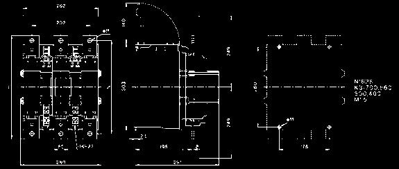
25 Dimensions / Position of Terminals Contactors J7KN-10D/14D/18D/22D(-4)... J7KN-10D-10 to J7KN-22D-10 J7KN-10D-01 to J7KN-22D-01 J7KN-10D-4_ to J7KN-22D-4_ J7KNG-10/14/18/22(-4)...D J7KNG D J7KNG D J7KNG D J7KNG D J7KNG D J7KNG D J7KNG D J7KNG D J7KNG-10-4_...D J7KNG-14-4_...D J7KNG-18-4_...D J7KNG-22-4_...D Ø M J7KN-10D/14D/18D/22D...D J7KN-10D-10...D J7KN-14D-10...D J7KN-18D-10...D J7KN-22D-10...D J7KN-10D-01...D J7KN-14D-01...D J7KN-18D-01...D J7KN-22D-01...D J7KN-10D-4_...D J7KN-14D-4_...D J7KN-18D-4_...D J7KN-22D-4_...D J7KN-24/32/ J7KN-24 J7KN-32 J7KN Ø4, M J7KNG-24/32/40...D J7KNG-24...D J7KNG-32...D J7KNG-40...D A1 A L1 3 L2 5 L M T1 4 T2 6 T3 A1 A2 Motor Contactor J7KN 25


 155 137 70 M8 9 31.5 31.")

26 J7KN-24/32/40...D J7KN-24...D J7KN-32...D J7KN-40...D J7KN-50/62/ J7KN-50 J7KN-62 J7KN Ø M J7KN-50/62/74...D J7KN-50...D J7KN-62...D J7KN-74...D J7KN J7KN J7KN-90 J7KN-115 J7KN-90...D J7KN D ( 6) M J7KN J7KN J7KN-151 J7KN-176 J7KN-151 J7KN x Motor Contactor J7KN


27 J7KN J7KN J7KN J7KN J7KN J7KN J7KN J7KN J7KN J7KN J7KN J7KN J7KN J7KN Motor Contactor J7KN 27
28 Auxiliary contacts blocks J74KN-B J74KN-C J74KN-D_F J74KN-D_S J74KN-F Pneumatic Timer J74KN-B-TP... Mechanical Interlocks J74KN-B-ML J74KN-C-ML J74KN-D2-ML J74KN-E-ML Suppressor Units J74KN-C2-RC 28 Motor Contactor J7KN


29 Additional Terminals J74KN-LG-9030 J74KN-LG Terminals Cover J74KN-LG J74KN-LG J74KN-P Marking Systems Wiring Systems Drawing J74-WKR-B2 Drawing J74-WKR-C Drawing J74-WKSD-B2 Drawing J74-WKSD-C Motor Contactor J7KN 29
30 Do not use/install these products before having read the applicable precautions as listed in Cat. No. J09-EN-01 available from or on request from OMRON local sales office. ALL DIMENSIONS SHOWN ARE IN MILLIMETERS. Cat. No. J06E-EN-03A In the interest of product improvement, specifications are subject to change without notice. 30 Motor Contactor J7KN
Approved Standards. Motor Contactor. Main contactor. Accessoires. 21 Motor Contactor J7KN
 Motor Contactor Main contactor AC & DC operated Integrated auxiliary contacts Screw fixing and snap fitting (35 mm DIN rail) up to 45 kw Range from 4 to 110 kw (AC 3, 380/415V) Finger proof ( VBG 4) Accessoires
Latch for Contactors 4-pole see page 36. Ratings Rated Aux. Contacts Type Coil voltage 2) AC2 Current Built-in Additional 24 24V= DC 5
 AC2 Current Built-in Additional 24 24V= DC 5") 3-pole DC Operated Ratings Rated Aux. Contacts Type Coil voltage 1) AC2 Current Built-in Additional 24 24V= DC 5 AC3 see 48 60V= DC 6 380V AC1 page 34 110 110V= DC 7 400V 660V 220 220V= DC 8 415V 690V
3-pole DC Operated Ratings Rated Aux. Contacts Type Coil voltage 1) AC2 Current Built-in Additional 24 24V= DC 5 AC3 see 48 60V= DC 6 380V AC1 page 34 110 110V= DC 7 400V 660V 220 220V= DC 8 415V 690V
Approved Standards. Ordering Information. Mini Motor Contactor J7KNA. Model Number Legend. Main contactor. Accessories. Mini Motor Contactor J7KNA 1
 Mini Motor Contactor J7KNA ) Main contactor AC & DC operated Integrated auxiliary contacts Screw fixing and snap fitting (35 mm DIN-rail) Range from 4 to 5.5 (AC 3, 380/415V) 4 -main pole version (4 AC
Micro Contactor MA Series
 Relay-sized contactor, making it the world s smallest >3mm contact clearance acc. to IEC 60335-1 for Safety Applications Reversing contactor with mechanical interlock 3 Pole and 1 Aux. Contact NO or NC
Approved Standards. Ordering Information. Thermal Overload Relay J7TKN. Model Number Legend. Thermal Overload Relay. Accessories
 Thermal Overload Relay J7TKN ) Thermal Overload Relay Direct and separate mounting Single phasing sensivity according to IEC 60947-4-1 Finger proof (BGV A2) Accessories Set for single mounting Approved
Approved Standards. Ordering Information. Mini Contactor Relays 4-pole J7KNA-AR. Model Number Legend. Main contactor. Accessories
 Mini Contactor Relays 4-pole J7KN-R ) Main contactor C & DC operated 4-, 6- and 8-pole versions in different configurations Positively guided contacts Screw fixing and snap fitting (35 mm DIN rail) Rated
Technical Information
 C5 C5- C5- C5- C5- C5-550 ➊ 700 860 1000 1200 Rated Insulation Voltage U i to IEC 947-1 [V] 1000V 1000V 1000V 690V 690V UL/CS [V] 600V Rated Impulse Voltage U imp C5-550 / 700 / 860 [kv] 3.5 C5-1000 /
Contactor Catalogue. According to CE, IEC 947, EN Pole & 4 Pole Contactors 4kW - 160kW Thermal Overload
 According to CE, IEC 947, EN 60947 Contactor Catalogue 3 Pole & 4 Pole Contactors 4kW - 160kW Thermal Overload Mini-Contactors 4kW - 5.5kW DC Contactors Mini-Relays 10A Motor Starter DOL, Star-Delta Capacitor
CI-TI Contactors and motor starters Types CI 61 - CI 98
 Data sheet CI-TI Contactors and motor starters s CI 6 - CI 98 Contactors CI 6, CI 7, CI 86 and CI 98 switch powers of up to 0 kw, 7 kw, 45 kw and 55 kw respectively under 80 V - loads. Accessories include
General Catalogue. Quality made in D946E173
 General Catalogue Quality made in D946E173 Index Page Contactors, Motor-Starter (D677E) 3 Micro Contactors 9 Mini Contactors 19 Contactor Relays 33 Contactors 39 Starters 85 D.O.L. Starters 105 Overload
Other Devices. Installation Contactors Z-SCH. Connection diagrams Z-SCH NO 3 NO / 1 NC. Permitted Installation Positions
 Installation Contactors Z-SCH These switching devices have been designed and rated particularly for modular installation in modular distribution boxes for electrical installation or cabinets with device
Modular contactor for installation into distribution boards
 Modular contactor for installation into distribution boards Description Modular contactors are used for installation in consumer units in dwellings, business premises, hotels, hospitals, shopping centres,
Index. Page. General 4 Approvals 5 Technical Information 9 Mounting Information 10
 Index Page General 4 Approvals 5 Technical Information 9 Mounting Information 10 Micro Contactors 11 Micro Contactors 12 Micro Contactor Relays 14 Micro Reversing Contactors 18 Technical Information 20
Contactors Motor-Starters D677E121
 Contactors Motor-Starters D677E121 Index Page General 2 Approvals 3 Technical Information 5 Mounting Information 6 Mini Contactors 7 Mini Contactors 8 Interface Contactors 8 Mini Reversing Contactors 14
Motor Starters. Star-Delta Starters Open Type 86. Star-Delta Starters Enclosed 88 Enclosure for Star-Delta Starters 88.
 Motor Starters Star-Delta Starters Open Type 86 Star-Delta Starters Enclosed 88 Enclosure for Star-Delta Starters 88 Accessories 89 Reversing Contactors 90 Pole Changing Starters 92 Technical Data 94 Wiring
General Informations 2 Technical data 3 Basic designs 4-8
 Contents Page General Informations 2 Technical data 3 Basic designs 4-8 Cam Switches On-Off switches, Changeover switches 9-12 Star-Delta switches 13-15 Multi speed switches 16-20 Control switches 21-23
CI-TI Contactors and Motor Starters Type CI 6-50
 Data sheet CI-TI Contactors and Motor Starters CI 6-50 CI-TI contactors and motor starters provide trouble-free switching and maximum protection for costly motors and other electrical equipment. The components
AF series contactors (9 2650)
") R E32527 R E39322 contactors General purpose and motor applications AF series contactors (9 2650) 3- & 4-pole contactors General purpose up to 2700 A Motor applications up to 50 hp, 900 kw NEMA Sizes 00
R E32527 R E39322 contactors General purpose and motor applications AF series contactors (9 2650) 3- & 4-pole contactors General purpose up to 2700 A Motor applications up to 50 hp, 900 kw NEMA Sizes 00
A Contactors. Technical Information. CA4 Miniature Contactors. Technical Information A94 CA4. Switching Motor Loads.
 C4 Miniature Contactors Contactors C4 Rated Insulation Voltage U i to IEC 947-1 [V] 500V UL/CS [V] 600V Rated Impulse Voltage U imp [kv] 8 Rated Voltage U e Main Contacts C 50/60Hz [V] 230, 240, 400, 415,
AF series contactors (9 2650)
") R E32527 R E39322 contactors General purpose and motor applications AF series contactors (9 2650) 3- & 4-pole contactors General purpose up to 2700 A Motor applications up to 50 hp, 900 kw NEMA Sizes 00
R E32527 R E39322 contactors General purpose and motor applications AF series contactors (9 2650) 3- & 4-pole contactors General purpose up to 2700 A Motor applications up to 50 hp, 900 kw NEMA Sizes 00
Motors Automation Energy Transmission & Distribution Coatings. Automation Contactors - CWM Line
 Motors Automation Energy Transmission & Distribution Coatings Automation Contactors - CWM Line 2 Contactores Compactos CWC0 Contactors - CWM Line Sumary Presentation Accessories Overview 5 Three-Pole Contactors
Index. Manual Motor Starters 1. Auxiliary Contact Blocks 1. Trip Alarm Auxiliary 1. Switch. Shunt Release 1. Under-voltage Release 2.
 Index Index Page Manual Motor Starters 1 Auxiliary Contact Blocks 1 Trip Alarm Auxiliary 1 Switch Shunt Release 1 Under-voltage Release 2 Accessories 2 Busbar Connectors 2 Enclosures 2 Leistung, kw C mv
Technical Information
 Contactors Contactors 95(-EI) 110(-EI) 140(-EI) 180(-EI) 210-EI 250-EI 300-EI 420-EI 630-EI 860-EI Rated Insulation Voltage U i IEC, S, BS, SEV, VDE 0660 [V] 1000V UL; CS [V] 600V Rated Impulse Voltage
Industrial Contactors CTX 3 3P 185A - 800A
 87045 LIMOGES Cedex Telephone: +33 5 55 06 87 87 FAX: +33 5 55 06 88 88 Industrial Contactors CONTENTS PAGES 1. Description - Use... 1 2. Range... 1 3. Overall dimensions... 1 4. Installation - Connection...
Contactor Types CI 61-98
 MKING MODERN LIVING POSSIBLE Data sheet Contactor s CI 6-98 Contactors CI 6, CI 73, CI 86 and CI 98 switch powers of up to 30 kw, 37 kw, 45 kw and 55 kw respectively under 3 380 V C-3 loads. ccessories
MAKING MODERN LIVING POSSIBLE. Technical brochure. Minicontactors CI 5-
 MKING MODERN LIVING POSSIBLE Technical brochure Minicontactors CI 5- www.danfoss.com 2 IC.PD.C10.F3.02-520B4167 Danfoss /S, C-SMC, mr, 07-2010 Contents Page Minicontactor CI 5- Introduction...............................................................................4
Modular Contactors and Switches D681E121
 Modular Contactors and Switches D681E121 Modular Contactors and Switches Modular Contactors 2, 3 Aux. contact block 3 Accessories 3 Day Night Reloading Contactors 4 Safety Switches 5 Main Switches Emergency
D509E. Manual Motor - Starters
 D509E Manual Motor - Starters Index Page Manual Motors Starters 182 Auxilliary Contact Blocks 182 Trip Alarm Aux. Switch 182 Shunt Release 182 Under-voltage Release 183 Accessories 183 Busbar Connectors
Contactors RAST 5 D778E131
 Contactors RAST 5 D778E131 RAST 5 - exclusive for OEM-Partners 5 mm pitch connector system Advantages RAST 5 - Technology 59 mm Time saving installation Easy assembly without tools Tailor-made sockets,
AF09... AF30 3-pole Contactors up to 20 HP / 480 VAC
 AF0... AF0 -pole Contactors up to 20 HP / 480 VAC Contactors and Overload Relays Overview...2 AF0... AF0 -pole Contactors Ordering Details...4 Main Technical Data...20 DC Circuit switching...2 Main Accessory
DATASHEET - DILMC9-10(24VDC) Technical data General. Contactor, 3p+1N/O, 4kW/400V/AC3. Catalog No Eaton Catalog No. XTCEC009B10TD.
 Technical data General. Contactor, 3p+1N/O, 4kW/400V/AC3. Catalog No Eaton Catalog No. XTCEC009B10TD.") DATASHEET - DILMC9-10(24VDC) Technical data General Contactor, 3p+1N/O, 4kW/400V/AC3 Part no. DILMC9-10(24VDC) Catalog No. 277468 Eaton Catalog No. XTCEC009B10TD EL-Nummer 4110305 (Norway) Standards IEC/EN
DATASHEET - DILMC9-10(24VDC) Technical data General Contactor, 3p+1N/O, 4kW/400V/AC3 Part no. DILMC9-10(24VDC) Catalog No. 277468 Eaton Catalog No. XTCEC009B10TD EL-Nummer 4110305 (Norway) Standards IEC/EN
Capacitor Switching Contactors Type K3...-A, K3...-K
 Type K3...-A, K3...-K Features that matter: Patented design with significant damping on inrush-current Long-life contactors tested by FRAKO up to 100,000 switching operations Suitable for unchoked and
Series CA5 Contactors
 Series C5 Contactors The contactor for heavy industrial applications from 500HP to 900HP DISCONTINUED This series is being replaced by the C9 Series of contactors C5 Series contactors provide large horsepower
4 - Miniature controls
 Index -....1.22 Selection Contactors for connection to PLCs, B6S & B7S, 3 phase...6 Contactors, Interface, B6 & B7, 3 phase...5 Contactors, features...1 Contactors, mechanically interlocked, B6 & B7, 3
Bulletin 100-D IEC Contactors
 Bulletin 100-D IEC Contactors Electronic and conventional coils AC & DC Integrated PLC interface Low power pick-up & hold-in Wide voltage ranges Complete range of accessories Environmentally friendly Compact
Low voltage switch gear
 Low voltage switch gear Omron is an established global manufacturer of low voltage switch gear (LVSG) products, and the company s new series (J7) complements the existing portfolio. High power-handling
AF09... AF38 4-pole Contactors AC / DC Operated - with Screw Terminals
 AF09... AF38 4-pole Contactors AC / DC Operated - with Screw Terminals 25 to 55 A culus CE Application AF09... AF38 4-pole contactors are used for controlling power circuits up to 600 V AC and 240 V DC.
TeSys contactors. Use in category DC-1 (resistive loads; time constant L/R y 1 ms) Rated operational current Ie. to be wired in series
 Rated operational current Ie. to be wired in series") Selection 3-pole shockproof contactors FG d.c. supply Selection guide for utilisation categories DC-1 to DC-5 Use in category DC-1 (resistive loads; time constant L/R y 1 ms) Rated operational current
Selection 3-pole shockproof contactors FG d.c. supply Selection guide for utilisation categories DC-1 to DC-5 Use in category DC-1 (resistive loads; time constant L/R y 1 ms) Rated operational current
Mini Contactors CI 4-
 Data sheet Mini Contactors CI 4- Introduction CI 4 minicontactors cover the power range 1.5 to 5.9 kw and are available for a.c. and d.c. coil voltages. Characteristic of the minicontactors is that they
CI-TI TM Contactors and Motor Starters Contactors CI 6-50
 Data sheet CI-TI TM Contactors and Motor Starters Contactors CI 6-50 Description Danfoss contactors CI 6-50 cover the power range 2.2-25 kw. CI 6 is built up as a combined contactor/control relay. CI 9
Controls. CONTACTORS CWB Line (up to 40A)
") Controls CONTACTORS CWB Line (up to 40A) 0800 367 934 Contactors CWB Line (up to 40A) CONTACTORS CWB Line (up to 40A) Summary New WEG CWB Contactors 4 The Technology Within 6 Energy Savings 7 Easy Panel
Controls CONTACTORS CWB Line (up to 40A) 0800 367 934 Contactors CWB Line (up to 40A) CONTACTORS CWB Line (up to 40A) Summary New WEG CWB Contactors 4 The Technology Within 6 Energy Savings 7 Easy Panel
MODULAR DEVICES. 21. Isolator Switches. Low Voltage (Bell) Transformers. Time Switches (electromechanical)
 Transformers. Time Switches (electromechanical)") MODULAR DEVICES The range of two, three and four pole isolator switches are of a modular design and fit on DIN 50022 rail. Terminal capacity is 25mm 2. Isolator Switches Rating Poles Modules Reference
MODULAR DEVICES The range of two, three and four pole isolator switches are of a modular design and fit on DIN 50022 rail. Terminal capacity is 25mm 2. Isolator Switches Rating Poles Modules Reference
AF09... AF30 3-pole Contactors up to 25 HP / 600 VAC
 AF09... AF0 -pole Contactors up to 25 HP / 600 VAC Contactors and Overload Relays Overview.../0 AF09... AF0 -pole Contactors.../2 Main Technical Data.../8 Main Accessory Fitting Details.../2 Main Accessory.../24
Technical Information
 Miniature Technical Information -09-12 Rated Insulation Voltage U i to IEC947-1 [V] 690V UL/CS [V] 600V Rated Impulse Voltage Withstand U imp [kv] 6 Rated Voltage Ue-Main Contacts C 50/60Hz [V] 230, 240,
Description. Positive safety relays
 Type N & KC Positive safety Description A.C. or D.C. operated DIN rail or panel mounting 600 volt heavy duty design, A600-10 amp, Q300-5 amp Snap-on accessories available: 1 & 4 pole adder deck Pneumatic
UL & CSA Technical data A/AE9 A/AE/AF110, AL9 AL40 AC & DC operated
 11Across the line UL & CSA Technical data A/AE9 A/AE/AF110, AL9 AL40 AC & DC operated contactor frame size A/AE/AL A/AE/AL A/AE/AL A/AE/AL A/AE/AL A/AE/AL A/AE/AF A/AE/AF A/AE/AF A/AE/AF A/AE/AF A/AE/AF
3RT14 Contactors with 3 Main Contacts
 3RT14 Contactors with 3 Main Contacts for Switching Resistive Loads Contactor Size 3RT14 46 Mechanical endurance Oper. 10 million Electrical endurance Oper. 0.5 million C-1 utilization category at I e
The contactor for large horsepower applications
 Series The complete contactor for heavy industrial applications from 500HP to 900HP R Series contactors provide large horsepower performance with a design that is up to 40% smaller than traditional contactors
Mini DC - Isolators for Photovoltaic
 Mini DC - Isolators for Photovoltaic acc. to IEC 60364-7-712 Quality made in D1024E171 Technical catalogues and news under: www.benedict.at Contactors Motor-Starter Mini-Contactors Contactors Overload
General_technical_data Series
 Slow-make switching element Switching system The double-break, slow-make switching element is equipped with one or two independent contact systems, acting as normally open or normally closed contact. The
Circuit-Breakers M4 166 for motor protection. Auxiliary contacts 167 Signalling switch Auxiliary releases
 Index Page Circuit-Breakers M4 166 for motor protection Auxiliary contacts 167 Signalling switch Auxiliary releases Insulated 3-pole busbar system 168 Terminal block DIN-rail adapters 169 Busbar adapters
Page. Circuit-Breakers M4 2 for motor protection. Auxiliary contacts 3 Signalling switch Auxiliary releases
 Circuit Breakers M4 Page Circuit-Breakers M4 2 for motor protection Auxiliary contacts 3 Signalling switch Auxiliary releases Insulated 3-pole busbar system 4 Terminal block DIN-rail adapters 5 Busbar
Application Mini Contactors for Motors and Resistive Loads
 Delivery program Contactor, 4p, 4kW/400V/AC3 Part no. DILEM4-G(24VDC) Catalog No. 012701 Eaton Catalog No. XTMF9A00TD Product range Contactors Application Mini Contactors for Motors and Resistive Loads
Approbationen IEC/EN ; UL 508; CSA-C22.2 No ; CE marking
 Contactor,4kW/400V,DCoperated Partno. DILEM-10-G(24VDC) Articleno. 010213 Program Product range Contactors Subrange DILEM contactors Application Mini Contactors for Motors and Resistive Loads Description
Essential equipment for all your requirements
 NEW CTX CONTACTORS Essential equipment for all your requirements 9 A TO 310 A THREE-POLE INDUSTRIAL CONTACTORS CTX three-pole industrial contactors, a sense of family The new range of CTX contactors provides
General + Definite Purpose Contactors
 General + Definite Purpose General Information... 2 Horse Power Rating Charts... 4 Contact Life... 8 Contactor Number Structure... Series C8 Miniature and Starters... 3 ccessories... 2 Contactor Cross
Contactor Relays 3TH30
 Contactor Relays 3TH30 Reliability and safety are pre-requisites in the choice of the control contactor. Siemens 3TH30 contactor relays satisfy these criteria and thus offer the right choice to the customer.
Meta Solution. Contactors and Overload relays
 Meta Solution Contactors and Overload relays Meta Solution New generation of Contactors from LSIS Contactors and Overload Relays Metasol Contactors Designed to show superior technology: The Metasol series
Contactors. Mini-contactors type LC1-SKGC for use in modular panels. Conforming to standards IEC/EN , IEC/EN , NF C , VDE 0660
 Characteristics Environment Rated insulation voltage (Ui) Conforming to IEC/EN 60947-1, V 690 IEC/EN 60947-4-1, VDE 0110 gr C, CSA - n 14, UL 508.1 Conforming to standards IEC/EN 60947-1, IEC/EN 60947-4-1,
TeSys contactors 5. Characteristics 5. Mini-contactors TeSys LC1 SK and LP1 SK. Environment Rated insulation voltage (Ui) 5/30
 5/30") Characteristics TeSys contactors Mini-contactors TeSys LC SK and LP SK Environment Rated insulation voltage (Ui) Conforming to 0, VDE 00 gr C,BS, CSA - n, UL 0 V 0 Conforming to standards IEC 0, NF C -0,
Characteristics TeSys contactors Mini-contactors TeSys LC SK and LP SK Environment Rated insulation voltage (Ui) Conforming to 0, VDE 00 gr C,BS, CSA - n, UL 0 V 0 Conforming to standards IEC 0, NF C -0,
Ktec Contactors and thermal overloads
 Contactors and thermal overloads Techna KTEC series contactors provide a complete solution for your ac contactor requirements.the range carries TUV, UL & CSA certification, for use in Europe, North America
ASL09..S 3-pole Contactors - Spring Terminals
 4 kw 5 hp ASL09..S 3-pole Contactors - Spring DC Operated Description - 3-pole contactors with spring terminals, - N.C. or N.O. built-in auxiliary contact, - Low coil consumption, - Polarity on the coil
W Datasheet: DIN Rail Contactors, series AMPARO
 W Datasheet: DIN Rail Contactors, series AMPARO W SCHRACK-INFO For suiting of fans, pumps, heating & lighting Noise reducing design Low vibration on DIN-rail 230V 50/60Hz oder 24V 50/60 Hz coil DIN-Rail
and Refrigeration Institute). CNX Special Purpose Contactors
. CNX Special Purpose Contactors") Series C7 Special Use Contactors Contactors designed and labeled for specific industrial applications Special Use Contactors Hydraulic elevator duty contactors HVC rated contactors Lighting contactors
Series C7 Special Use Contactors Contactors designed and labeled for specific industrial applications Special Use Contactors Hydraulic elevator duty contactors HVC rated contactors Lighting contactors
3 - Protection components Motor circuit-breakers
 Contents 0 - Protection components Motor circuit-breakers protection components for the motor protection Thermal-magnetic motor circuit-breakers Selection guide..............................................page
FUJI Magnetic Contactors and Motor Starters
 FUJI Magnetic Contactors and Motor Starters Technical Information AEH28a CONTENTS Chapter Contactors and Starters - International standards... 4-2 Ratings and specifications... 8-3 Performance and characteristics...
Short form catalogue. Motor protection & control
 Short form catalogue Star Series Motor protection & control Motor Protection and Control up to 25 HP / 600 VAC Overview...2 Contactors and Overload Relays...11 4-pole Contactors...41 Control Relays...59
3TM Vacuum Contactors
 Catalog Extract HG 11.23 Edition 2016 Catalog Extract Medium-Voltage Equipment siemens.com/3tm R-HG11-343.psd 2 Siemens HG 11.23 2016 Contents Medium-Voltage Equipment Catalog Extract HG 11.23 2016 Contents
General + Definite Purpose Contactors
 General + Definite Purpose Contactors General Information... 2 Horse Power Rating Charts... 4 Contact Life... 8 Contactor Number Structure... Contactors Series C8 Miniature Contactors and Starters... 3
Instructions Contact numbers to EN Coil terminal markings to EN Integrated diode-resistor combination Coil rating 2.
 Deliveryprogramme Contactorrelay,3N/O+1N/C,DCcurrent Partno. DILER-31-G-C(110VDC) Articleno. 231831 CatalogNo. XTRMC10A31E0 Product range DILER Mini-contactors Application Contactor relays Description
MS25 59 MS RI RI RV 60, RV 120 RS 76 CDB3X 77 Surface Mounted (INO) and Flush Munted (IPO) Compact Distribution Boards 78
 and Flush Munted (IPO) Compact Distribution Boards 78") index Contents: Page New Products 4 Contactors K03, K07 Mini Contactors 10 BR6 Thermal overload relay 16 KNL6 - KNL30 Contactors 18 KNL6G - KNL30G Contactors 25 KNL40, KNL 65 Contactors 29 KNL80 - KNL110
index Contents: Page New Products 4 Contactors K03, K07 Mini Contactors 10 BR6 Thermal overload relay 16 KNL6 - KNL30 Contactors 18 KNL6G - KNL30G Contactors 25 KNL40, KNL 65 Contactors 29 KNL80 - KNL110
AF / AF12Z pole Contactors AC / DC Operated - with Screw Terminals
 Technical Datasheet 1SBC101404D0201 24/03/11-30-10-.. / Z-30-10-.. 3-pole Contactors AC / DC Operated - with Screw Terminals (Z) contactors are used for controlling power circuits up to 690 V AC and 220
SD Series Non-Fused Load Switches
 SD Series Non-Fused Load Switches The SD1 and SD2 series of non-fused load switches are listed as Manual Motor Controllers and are designed for use in local motor isolation. The SD series of modular load
Characteristics TeSys contactors 0 TeSys k contactors and reversing contactors
 90 Characteristics TeSys contactors 0 TeSys k contactors and reversing contactors Environment characteristics Conforming to standards IEC 60947, NF C 63-110, VDE 0660, BS 5424 Product certifications LCp
GV2, GV3, and GV7 Manual Motor Starters, Controllers, and Protectors Standard Features
 Standard Features Table : Standard Features GV2ME GV2P GV3P GV7RE/GV7RS 0. to 32 A Up to 20 hp @ 460 V 0 SCCR @ 480 V Push Button Operator 0. to 30 A Up to 5 hp @ 460 V 50 SCCR @ 480 V Rotary Handle Operator
Technical Information
 -100 Controller IEC Performance Data (CSA C22.2, UL 508 No. 14 in connection with a short-circuit protection device Catalog No. -100... 25A 40A 63A 90A Maximum Short-Circuit Current 480V [ka] 65 65 42
AF40... AF96 3-pole contactors Technical data
 Main pole - Utilization characteristics according to IEC Standards IEC 60947- / 60947-4- and EN 60947- / 60947-4- Rated operational voltage Ue max. 690 V Rated frequency (without derating) 50 / 60 Hz Conventional
Contact us. ABB France Electrification Products Division Low Voltage Products and Systems 3, rue Jean Perrin F Chassieu cedex / France
 Contact us ABB France Electrification Products Division Low Voltage Products and Systems 3, rue Jean Perrin F-69687 Chassieu cedex / France You can find the address of your local sales organisation on
Technical data. Miniature Circuit Breakers. System pro M. System pro M
 Technical data System pro M System pro M 1 Prior to connection of aluminium conductors ensure that their contact points are cleaned, brushed and coated with grease. The contact terminals must be tighten
Quick selection table
 Quick selection table Contactors... 100 to 800A Frame size 100A 15A 150A -pole Contactors s AC/DC common coil See page 46 for more details CGC-100 CGC-15 CGC-150 See page 46 for more details Ratings /
Modular contactors and relays
 pages /4 to / pages /8 and /9 pages /10 and /11 pages /12 and /13 Presentation and standards Presentation Designed for use in modular panels and enclosures, these contactors feature : i Easy installation
Bulletin 825 SMM Smart Motor Manager
 Bulletin 825 SMM Smart Motor Manager Your order must include: Cat. no. of the Smart Motor Manager selected with supply Voltage Suffix Code, Cat. no. of Converter Module selected, and, If required, Cat.
IEC Utilization Categories (Explanation)
") IEC Utilization Categories (Explanation) IEC Utilization Categories Voltage Category Typical Applications A.C. A.C. and D.C. D.C. AC AC AC AC ACa ACb AC6a AC6b AC7a AC7b AC8a AC8b AC AC AC AC AC AC AC
IEC Utilization Categories (Explanation) IEC Utilization Categories Voltage Category Typical Applications A.C. A.C. and D.C. D.C. AC AC AC AC ACa ACb AC6a AC6b AC7a AC7b AC8a AC8b AC AC AC AC AC AC AC
Application Mini Contactors for Motors and Resistive Loads
 Deliveryprogramme Contactor,3p+1N/O,4kW/400V/AC3 Partno. DILEM-10-G(24VDC) Articleno. 010213 CatalogNo. XTMC9A10TD Product range Contactors Application Mini Contactors for Motors and Resistive Loads Subrange
Data sheet. CI-TI TM Contactors and Motor Starters Circuit Breakers CTI B1427
 Data sheet CI-TI TM Contactors and Motor Starters Circuit Breakers November 2002 DKACT.PD.C00.L2.02 520B1427 Introduction Circuit breakers/manual motor starters cover the power ranges 0.09-12.5 kw This
Meta Solution. Contactors and Overload relays
 Meta Solution Contactors and Overload relays New generation of Contactors from LS Industrial Systems Contactors and Overload Relays Metasol Contactors Designed to show superior technology: The Metasol
Safety Relay Unit. Ordering Information. Ideal for Safety Door and Emergency Stop Switch Circuits for Machines in European Countries
 Safety Relay Unit Ideal for Safety Door and Emergency Stop Switch Circuits for Machines in European Countries Two-pole slim models that are only 22.5 mm wide, three-pole models that are only 68 mm wide,
For Info: Phone: Fax:
 Page -2 TWO POLES IEC rated current Ith: 20A (AC1) IEC operational power: 1.3kW (AC3 230V) Ideal for domestic applications. Page -2 THREE AND FOUR POLES IEC rated current Ith: 25A, 40A and 63A (AC1) IEC
AE 9... AE 40 Contactors NE... Contactor Relays
 Technical data AE 9... AE 0 Contactors NE... Contactor Relays AE 9... AE 0 Contactors NE.. Contactor Relays Contents AE 9... AE 0 Contactors Description... 2 Ordering Details... 3 Technical Data... Terminal
Instructions Contact numbers to EN Coil terminal markings to EN Integrated diode-resistor combination Coil rating 2.
 Deliveryprogram Contactorrelay,2N/O+2N/C,DCcurrent Partno. DILER-22-G(220VDC) Articleno. 010091 CatalogNo. XTRM10A22BD Product range DILER Mini-contactors Application Contactor relays Description with
TAE pole Contactors
 TAE9...26 3-pole Contactors d.c. operated with double-winding coil SB8033C3 Utilisation TAE9 to TAE26 contactors are a compliment to the DC control contactor range. The coils have large voltage ranges
AF / AF09Z pole Contactors AC / DC Operated - with Screw Terminals
 Technical Datasheet SBC042D020 06/04/ -22-00-.. / Z-22-00-.. 4-pole Contactors AC / DC Operated - with Screw Terminals (Z) contactors are used for controlling power circuits up to 690 V AC and 440 V DC.
Industrial contactors CTX-1
 87045 LIMOGES Cedex Telephone number: +33 5 55 06 87 87 Fax: +33 5 55 06 88 88 Industrial contactors /04/05/10/12/14/15/20/22/24/25/30/32/34/35/40/42/44/45 CONTENTS PAGE 1. Use... 1 2. Range... 1 3. Electrical
Switches Unlimited Phone: * Fax:
 For Info: sales@switchesunlimited.com www.switchesunlimited.com Phone: 800-1-0487 Fax: 718-67-6370 Page -4 Page -8 THREE-POLE CONTACTORS IEC Ith ratings in AC1 duty at 40 C: 16 to 1600A IEC Ie ratings
Selection Guide Motor Control Device Solutions
 Selection Guide Motor Control Device Solutions Expect more and get it from c3controls. Our portfolio of Motor Control Devices consists of worldclass products designed and manufactured to meet your requirements
Star Series Motor protection & control
 Contact us ABB Inc. Low Voltage Control Products 16250 W. Glendale Drive New Berlin, WI 53151 Phone: 888-385-1221 Fax: 800-726-41 USA Technical support & Customer Service: 888-385-1221, Option 4 7:30AM
Page 2-4 Page 2-8. Page Page 2-13
 Page -4 Page -8 THREE-POLE CONTACTORS IEC Ith ratings in AC1 duty at 40 C: 16 to 1600A IEC Ie ratings in AC3 440V duty: 6 to 630A IEC Power ratings in AC3 400V duty:. to 335kW UL/CSA ratings: 3 to 500HP
AF / AF38Z pole Contactors AC / DC Operated - with Screw Terminals
 Technical Datasheet 1SBC101412D0201 25/03/11-30-00-.. / Z-30-00-.. 3-pole Contactors AC / DC Operated - with Screw Terminals (Z) contactors are used for controlling power circuits up to 690 V AC and 220
FMotor Circuit Controllers
 Technical Information Motor Circuit Controller IEC Performance Data Catalog Number KTA7-25S...32S 0.16A 0.25A 0.4A 0.63A 1A 1.6A 2.5A 4A 6.3A 10A 16A 20A 25A 29A 32A Rated Operational Current, I e [A]
ADS7 AC Contactor Starters
 ADS7 AC Contactor Starters ADS7 starters fully comply with BS EN 60947-4-1, IEC 60947-4-1 and VDE 0660. The range offers a multitude of configurations and optional features including a complete choice