Controls. CONTACTORS CWB Line (up to 40A)
|
|
|
- Elfrieda Reeves
- 5 years ago
- Views:
Transcription

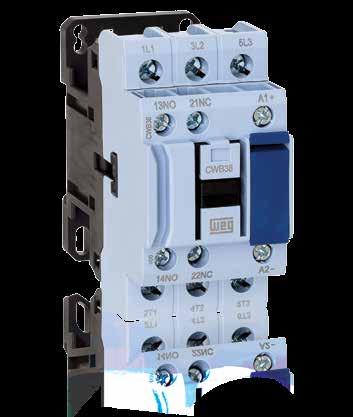

1 Controls CONTACTORS CWB Line (up to 40A)

2 Contactors CWB Line (up to 40A)
3 CONTACTORS CWB Line (up to 40A) Summary New WEG CWB Contactors 4 The Technology Within 6 Energy Savings 7 Easy Panel Optimization 8 Flexibility and Modularity in Assembly of Electric Panels 10 Safety 12 Selection Table 13 Accessories 14 Technical Data 16 Dimensions (mm) 30 Contactors CWB Line (up to 40A) 3


4 New WEG CWB Contactors Developed according to IEC and UL 508 international standards, the new WEG CWB line of contactors meets the requirements of a wide range of industrial applications worldwide. 4 Contactors CWB Line (up to 40A)


5 WEG CWB Contactors are modular and compact but at the same time robust and highly reliable. Easy installation and energy savings meet the expectations of users who want to perform automation in a more simple and practical way. The CWBs are designed with the visual pattern and identity of WEG, a brand recognized worldwide for its quality. Contactors CWB Line (up to 40A) 5


6 The Technology Within The use of finite-element analysis and state-of-the-art modeling softwares for simulation of electromagnetic and electromechanical systems provide WEG CWB contactors with an improved project with reduced contact bouncing. The outcome reached by WEG s R&D team ensures a product with long mechanical and electrical lifespan in a reduced size and with lower energy consumption. The electric contacts of CWB contactors are manufactured with special silver alloys which ensure excellent electric conductibility and high contact reliability. During operation, the doublebreak contacts and arc chutes ensure fast arc quenching and provide high resistance against the wear effects of the electric arc and, consequently, a long electrical lifespan. Analysis of CWB electromagnetic system. Simulation of plastic injection molding of CWB contact carrier. CWB contactors are manufactured with the best raw materials from top international suppliers and with WEG high quality components, using high precision plastic injection molds and stamping tools, ensuring very reliable products with the best cost-benefit in the market. 6 Contactors CWB Line (up to 40A)


7 Energy Savings Low Consumption Coils The low-consumption coils of new WEG contactors of up to 38 A allow safe operation with minimum energy consumption of up to 6 W in DC and up to 7.5 VA in AC. Besides energy savings, the low consumption of the coils of CWB contactors allows reducing the power supply of control transformers. When well dimensioned and properly applied, the traditional starting methods of electric motors, such as DOL (reversing or non-reversing) and star-delta using contactors, are the safest and best cost-benefit means to start and protect electric motors in low voltage. Up to at least 55 kw, DOL and star-delta starters using contactors are still the best and most widely used starting methods in all kinds of industries worldwide. Even when electronic methods are used for the start and control of motors, such as VSDs and Soft-Starters, the contactors continue to be necessary in combination with the electronic devices. Therefore, one can only imagine the huge number of contactors installed and in operation all over the world. Thus, CWB contactors are designed to operate in a safe and reliable way with the lowest energy consumption. Coil Consumption DC Operated Contactor Standard contactor CWB Energy saving 30% DC Coils with no Inrush Pick-Up Current Besides low energy consumption, DC coils allow direct control of CWB contactors via PLC or digital outputs of devices such as VSDs or Soft-Starters without the need of interface relays. SS PLC VSD Eco-Friendly The CWB line uses only nontoxic and eco-friendly materials that are safe and sustainable. Contactors CWB Line (up to 40A) 7
, CWB contactors lead to an overall reduction in size of electric panels if compared to traditional solutions of contactors with")
 makes the application of CWB contactors more flexible in most automation")

8 Easy Panel Optimization Compact Solution Because they are compact, 45 mm wide and available in up to 38 A ( / 415 V AC-3 and V UL 3-ph), CWB contactors lead to an overall reduction in size of electric panels if compared to traditional solutions of contactors with the same ratings. Built-In Auxiliary Contacts 1NO + 1NC The configuration of two built-in auxiliary contacts (1NO + 1NC) makes the application of CWB contactors more flexible in most automation systems, contributing to the optimization of internal space of electrical panels. Allows +1 Contactor 45 mm 55 mm Zero-Width Mechanical Interlock For applications which require mechanical interlock between contactors, WEG has developed a new mechanical system that ensures compact and easy mounting without the need of any tools. WEG s new mechanical interlock system allows the mechanical interlock between two contactors of the CWB line with zero additional side space and it is possible to assemble 90 mm wide reversing starters of up to 38 A. 90 mm 2 x 45 mm 8 Contactors CWB Line (up to 40A)


 to")

9 Simple and Compact Mounting of Surge Suppressor Blocks The coils of CWB contactors operate smoothly with a low level of disturbance in the control circuits. However, in order to reduce voltage surges due to the coil switching even further, WEG has developed surge suppressor blocks especially for the CWB line of contactors, which ensure limitation or even completely eliminate the undesired interferences that may be caused on opening the contactor coil. Surge suppressor blocks are easily mounted on CWB contactors without the need of any kind of tools and also without increasing volume. Contactor Coil Operated on AC or DC Wide range of voltages available in only two coil versions (one for AC and another for DC) to fit the whole range of contactors from 9 to 38 A. Easy AC coil replacement and visual coil voltage indication. Contactor with AC coil Contactor with DC coil CWB Line Standard Contactors More Simple and Organized Control Circuits In order to optimize space in electric panels even more, the WEG CWB contactor line has a front channel for the passage of control cables. This could reduce or eliminate the need of control cable passage through the side or front part of contactors providing a cleaner and more organized assembly of the control circuit. Contactors CWB Line (up to 40A) 9


10 Flexibility and Modularity in Assembly of Electric Panels Easy-Connection Busbars and Connectors The harmonious integration between the WEG CWB line of contactors and overload relays and motor protective circuit breakers allows fast and easy assembly of compact starters and protection sets of LV electric motors with excellent cost-benefit. The modularity and flexibility of easy-connection busbars and connectors reduce assembly time, besides preventing errors. Available for CWB contactors up to 38 A, easy-connection allows the combined assembly with WEG motor protective circuit breakers and thermal overload relays forming compact and robust DOL starters (reversing and non-reversing) and star-delta starters. 10 Contactors CWB Line (up to 40A)


11 Easy Access Power and Control Terminals All power terminals, auxiliary contacts and coils provide users with fast front access, facilitating installation, measurements and interventions for preventive and corrective maintenance of starters. Additional Contact Blocks Besides the 1NO + 1NC built-in auxiliary contacts, in order to meet the most complex control needs, WEG has also developed auxiliary high performance contact blocks which can be easily mounted on the front or side of CWB contactors, allowing the combination of up to six auxiliary contacts per contactor up to 38 A. An important characteristic of the side auxiliary contact blocks of the CWB line is the small dimension (only 9 mm wide) which meets the requirements of modularity, allowing more compact combinations of motor starters with motor protective circuit breakers when easyconnection busbars are used. Panel Assembly Flexibility CWB contactors can be easily assembled on panels using 35 mm DIN rails or screws because their oblong holes are compatible with the old and traditional lines of contactors on the market. Contactors CWB Line (up to 40A) 11

12 Safety Safety Against Accidental Contact All power and control terminals of CWB contactors have IP20 degree of protection, ensuring total safety against accidental frontal contact. Safety-Related Applications In automation systems of machines and equipment, it is common to use special contactors in combination with specific safety relays. The new WEG CWB contactors allow this combination due to the arrangement of the contacts which meets IEC Annex F (Mirror Contact) and IEC Annex L (Mechanically Linked Contact) requirements. IEC Mechanically linked contacts IEC Mirror contacts 12 Contactors CWB Line (up to 40A)
 I e = Ith (U e 690 V) θ 55 C AC-1 Orientative rated operational power of three-phase motors 50/60 Hz Built-in auxliary contacts Reference code AC coil DC coil 220 V 240 V 380 V 400 V 415")
13 Selection Table Three-Pole CWB Contactors from 9 up to 38 A (AC-3) I e máx. (U e 440 V) I e = Ith (U e 690 V) θ 55 C AC-1 Orientative rated operational power of three-phase motors 50/60 Hz Built-in auxliary contacts Reference code AC coil DC coil 220 V 240 V 380 V 400 V 415 V 440 V 500 V 660 V 690 V AC A A kw /hp kw /hp kw /hp kw /hp kw /hp NO NC / / / / / CWB / / / / / CWB / / / / / CWB / / / / / CWB / / / / / CWB / / / / / CWB To complete the reference code, replace by the appropriate coil voltage code. Coil voltage code D02 D07 D13 D15 D17 D77 D23 D24 D25 D33 D34 D35 D36 D39 D45 V (50/60 Hz) Coil voltage code C02 C03 C07 C09 C12 C13 C15 V dc Note: Other coil voltages available upon request. 3 1 Weight kg Contactors CWB Line (up to 40A) 13


14 Accessories Overview Contactors CWB Front mounted auxiliary contact blocks BFB 3 Side mounted auxiliary contact blocks BLB 4 Side mounted auxiliary contact blocks BLRB 5 Mechanical interlock kit IM1 6 Easy connection for reversing starters EC-R1 7 Easy connection for star-delta starters EC-SD1 8 Surge suppressor blocks RCB, VRB, DIB and DIZB 14 Contactors CWB Line (up to 40A)
 2 0 BFB-20 0 2 BFB-02 1) 2 2 BFB-22 1) 2 2 BFB-22 EL 3) 0.")
 Auxiliary contact blocks according to EN 50012 1 1 BFB-11 EN 1) 2 0 BFB-20 EN 0 2 BFB-02 EN 1) 2 2 BFB-22 EN 1) 4 0 BFB-40 EN 0.")
15 Accessories and Spare Parts Front Mounted Auxiliary Contact Blocks 4) Illustrative picture For use with Max. no of additional contacts / contactor Auxiliary contacts NO NC Reference Weight kg 1 1 BFB-11 1) 2 0 BFB BFB-02 1) 2 2 BFB-22 1) 2 2 BFB-22 EL 3) BFB BFB-04 1) 3 1 BFB-31 1) CWB / CWB BFB-13 1) Auxiliary contact blocks according to EN BFB-11 EN 1) 2 0 BFB-20 EN 0 2 BFB-02 EN 1) 2 2 BFB-22 EN 1) 4 0 BFB-40 EN BFB-04 EN 1) 3 1 BFB-31 EN 1) 1 3 BFB-13 EN 1) Side Mounted Auxiliary Contact Block 4) Illustrative picture For use with Max. no of additional contacts / contactor Auxiliary contacts NO NC Reference Weight kg 1 1 BLB11 1) 2 0 BLB20 CWB / CWB BLB02 1) 1 1 BLRB11 1)2) BLRB20 2) 0 2 BLRB02 1)2) Plug-In Surge Suppressors Illustrative picture For use with Voltage Diagram Reference V 50/60 Hz RCB-D V 50/60 Hz RCB-D V 50/60 Hz RCB-D V 50/60 Hz / V dc VRB-E V 50/60 Hz / V dc VRB-E V 50/60 Hz / V dc VRB-E50 CWB V 50/60 Hz / V dc VRB-E V 50/60 Hz VRB-D73 Weight kg V dc DIB-C V dc DIZB-C26 Notes: 1) The arrangement of the contacts meets IEC Annex F (Mirror Contact) and IEC Annex L (Mechanically Linked Contact) requirements. 2) For combination of 2 side-mounted auxiliary contact blocks at the same side of the contactor. 3) BFB-22-EL: besides the regular contacts NO and NC, there are two special contacts: early make and late break. 4) The maximum number of auxiliary contacts assembled on the contactor is 4. Contactors CWB Line (up to 40A) 15

 3-phase motors - IV-poles - 50/60 Hz - 1800 rpm")
16 Mechanical Interlock Kit Illustrative picture For use with Description Reference code Weight kg CWB Kit for mechanical interlock between two contactors of the CWB line with no additional side space. Contains: 1 interlock unit + 2 fixing clips. Note: It is not possible to interlock one contactor with AC coil with another with DC coil. IM Easy Connection Busbars for Reversing Starters Illustrative picture For use with K1 = K2 220 / 240 V kw / HP Maximum rated operational power (AC-3) 3-phase motors - IV-poles - 50/60 Hz rpm 380 / 400 V kw / HP 415 / 440 V kw / HP CWB9 2.2 / / / 6 CWB12 3 / / / 7.5 CWB / / / 12.5 CWB / / / 15 CWB / / / 20 CWB / / / 25 Reference code Weight kg EC-R A A1 A A2 Circuit diagram Easy Connection Busbars for Star-Delta Starters Illustrative picture K1 = K2 For use with K3 220 / 240 V kw / HP Maximum rated operational power (AC-3) 3-phase motors - IV-poles - 50/60 Hz rpm 380 / 400 V kw / HP 415 / 440 V kw / HP CWB9 CWB9 3.7 / / / 10 CWB12 CWB9 5.5 / / / 15 CWB18 CWB9 7.5 / / / 15 CWB18 CWB / / / 20 CWB25 CWB18 11 / / / 30 CWB32 CWB18 15 / / / 40 CWB38 CWB / / / 50 Reference code Weight kg EC-SD A A A1 A A A2 Circuit diagram 16 Contactors CWB Line (up to 40A)

17 Individual Spare Coil for Contactors 1) Illustrative picture For use with Control Reference code Weight kg CWB AC 50/60 Hz BRB Note: 1) Spare DC coils not available. To complete the reference code, replace by the appropriate coil voltage code. Alternating Current Coil voltage code D02 D07 D13 D15 D17 D77 D23 D24 D25 D33 D34 D35 D36 D39 D45 V (50/60 Hz) Note: Other coil voltages available upon request. Contactors CWB Line (up to 40A) 17
18 Contactors - Technical Data Terminal Markings According to IEC Diagram Configuration NO NC Reference code 3-poles contactors with built-in auxiliary contacts CWB t CWB t CWB t CWB t CWB t CWB t Front mounted auxiliary contact blocks BFB BFB BFB BFB BFB BFB-22-EL BFB BFB BFB Contactors CWB Line (up to 40A)
19 Diagram Configuration NO NC Reference code Side mounted auxiliary contact blocks BLB BLB BLB BLRB BLRB BLRB Contactors CWB Line (up to 40A) 19
20 Terminal Markings According to EN Diagram Configuration NO NC Reference code Front mounting auxiliary contact blocks BFB-20 EN BFB-11 EN BFB-02 EN BFB-40 EN BFB-22 EN BFB-04 EN BFB-31EN BFB-13 EN Contactors CWB Line (up to 40A)
21 General Data Reference code CWB9 CWB12 CWB18 CWB25 CWB32 CWB38 Standards IEC , IEC , IEC , UL 508 Rated insulation voltage U i (pollution degree 3) IEC (V) 690 V UL, CSA (V) 600 V Rated impulse withstand voltage Uimp IEC (kv) 6 kv Rated operational frequency (Hz) Mechanical lifespan AC coil (million cycles) 10 DC coil (million cycles) 10 Electrical lifespan I e AC-3 (million cycles) Degree of protection (IEC 60529) Main circuit Control circuit and auxiliary contacts IP20 (front) IP20 (front) Dimensions W x H x D (mm) 45 x 78,4 x 89,5 (AC) / 95,7 (DC) 45 x 85 x 93 (AC) / 102 (DC) Mounting By screws or DIN 35 mm rail (EN 50022) Number of coil terminals Vibration resistance (IEC ) Shock resistance (½ sine wave =11ms - IEC ) Ambient temperature Altitude - rated values up to 1) AC operated contactors 2 DC operated contactors 2 Open contactor (g) 4 Closed contactor at U c (g) 4 Open contactor (g) Closed contactor at U c (g) Operating -25 ºC ºC Storage -55 ºC ºC 3000 m Control Circuit - Alternating Current (AC) Reference code CWB Rated insulation voltage U i IEC (V) 1000 (pollution degree 3) UL, CSA (V) 600 Standard coil voltages 50/60 Hz (V) Coil operating limits (xus) Coil 50/60 Hz Pick up (xus) up to 0.8 for 50 Hz / up to 0.85 for 60 Hz Drop out (xus) Power consumption 60 Hz operation 50 Hz operation Sealing (VA) Coil 50/60 Hz Power factor (cos ϕ) Pick up (VA) (Normally open) contact closing (ms) Operation time (Normally open) contact opening (ms) Thermal power dissipation 50/60 Hz (W) Control Circuit - Direct Current (DC) Reference code CWB Rated insulation voltage U i IEC (V) 1000 (pollution degree 3) UL, CSA (V) 600 Standard coil voltages 50/60 Hz (V) Coil operationg limits (xus) Pick up (xus) up to 0.8 Drop out (xus) Power consumption For 1.0 x Us and cold coil Sealing (W) 5.8 Pick up (W) 5.8 Operation time (Normally open) contact closing (ms) (Normally open) contact opening (ms) Average thermal power dissipation (W) 5.8 Note: 1) For site altitudes of 3000 to 4000 m, the adjustment factors are (0.90 x I e and 0.80 x U i ) and for site altitudes of 4000 to 5000 m, the adjustment factors are (0.80 x I e and 0.75 x U i ). Contactors CWB Line (up to 40A) 21
22 Main Contacts Reference code CWB9 CWB12 CWB18 CWB25 CWB32 CWB38 Rated operational current I e AC-4 (U e 440 V) (A) AC-3 (U e 440 V) (A) AC-1 (θ 55 ºC, U e 690 V) (A) Rated operational voltage U e UL, CSA (V) 600 IEC (V) 690 Rated thermal current I th (θ 55 ºC) (A) Making capacity - IEC (A) U e 440 V (A) Breaking capacity IEC U e = 500 V (A) U e = 690 V (A) s (A) Short-time current (no current flowing 10s (A) during recovery time of 15min and θ 40 ºC) 1min (A) min (A) Protection against short-circuits with V - UL/CSA (ka) 5 (gl/gg) Coordination type 1 (A) Impedance per pole (mω) Power dissipation per pole AC-1 (W) AC-3 (W) Utilization category AC-1 U e 440 V (A) Rated operational current I e AC-3 U e 500 V (A) U e 690 V (A) / 240 V (kw) (HP) (kw) / 400 V Orientative rated (HP) operational power (kw) of three-phase motors 415 / 440 V 50/60 Hz (HP) IV poles rpm (kw) V (HP) / 690 V (kw) (HP) Utilization category AC-4 U e 440 V (A) Rated operational current I e AC-4 U e 500 V (A) U e 690 V (A) / 240 V (kw) (HP) (kw) / 400 V Orientative rated (HP) operational power of three-phase motors (kw) / 440 V 50/60 Hz (HP) IV poles rpm ( cycles) (kw) V (HP) / 690 V (kw) (HP) Contactors CWB Line (up to 40A)
23 Reference code CWB9 CWB12 CWB18 CWB25 CWB32 CWB38 Utilization category AC-1 Conventional thermal current Ith (θ 55 ºC) (A) Rated operational current θ 60 ºC (U e 690 V) (A) / 240 V (kw) / 400 V (kw) Max. operational power θ 55 ºC (three-phase resistors) 415 / 440 V (kw) V (kw) / 690 V (kw) poles in parallel I e x 1.7 Current values for connection of 3 poles in parallel I e x poles in parallel I e x 3.2 Percentage of maximum operational current 600 ops./h (%) P (NO) Auxiliary Contacts Reference code CWB (built-in) BFB (front mounted) BLB (side mounted) Standards IEC Rated insulation voltage U i IEC (V) 1000 (pollution degree 3) UL, CSA (V) 600 Rated operational voltage U e UL, CSA (V) 600 IEC (V) 690 Conventional thermal current I th (θ 55 ºC) (A) 10 Rated operational current I e AC-15 (IEC ) DC-13 (IEC ) 220 / 230 V (A) / 440 V (A) V (A) / 690 V (A) V (A) 4 48 V (A) V (A) V (A) V (A) V (A) 0.1 Making capacity U e 690 V 50/60 Hz - AC-15 (A) 10 x I e Breaking capacity U e 400 V 50/60 Hz - AC-15 (A) 1 x I e Short-circuit protection max. fuse (gl/gg) (A) 10 Control circuit reliability (V / ma) 17 / 5 Electrical lifespan (million cycles) 1 Mechanical lifespan (million cycles) 10 Non-overlapping time between NO and NC contacts (ms) 1.5 Impedance per pole (mω) Contactors CWB Line (up to 40A) 23
24 UL Ratings Reference code CWB9 CWB12 CWB18 CWB25 CWB32 CWB V (HP) Horse power ~ 1Ø V (HP) V (HP) V (HP) Horse power ~ 3Ø 460 V (HP) V (HP) Short-circuit rating 5 ka V General purpose for 600 V V ac to 600 V ac, 50/60 Hz Coil ratings V dc NEMA Ratings Reference code CWB9 CWB18 CWB32 NEMA size V (HP) Horse power ~ 3Ø 230 V (HP) Normal starting duty 1) 460 V (HP) V (HP) Note: 1) When operation requires jogging (inching) or plugging or when normal operation requires continued operation in excess of 5 operations per minute, the Normal Starting Duty horsepower ratings are not applied. Terminal Capacity and Tightening Torque Reference code CWB9 - CWB18 CWB25 - CWB38 Conductors Connection Number of conductors mm 2 AWG mm 2 AWG Control and auxiliary circuits Terminal screw M4 Flat/Philips Power circuit Terminal screw M3.5 Flat/Philips Tightening torque (N.m / (lb.in)) Control and auxiliary circuits 1 / (8.8) 1 / (8.8) Power circuit 1.7 / (15) 2.5 / (22) Reference code BFB (front mounted) BLB (side mounted) Conductors Connection Number of conductors mm 2 AWG mm 2 AWG Auxiliary contact blocks Terminal screw M3.5 Flat/Philips Tightening torque (N.m / (lb.in)) 1 / (8.8) 1 / (8.8) 24 Contactors CWB Line (up to 40A)
25 Contactors for Switching Lamps in Lighting Circuits When a contactor is chosen for switching lighting circuits it should be taken into account the type, number and power of lamps, the values of current during the starting phase and in the steady-state, power factor and the presence or not of compensation capacitors. Compensation capacitors and electronic devices are usually responsible for high inrush currents and may stress the contactors in lighting installations. The current consumption of lighting equipment typically increases when the voltage decreases so it is recommended to utilize a maximum of 90% of the thermal rated current of the contactor. All the aforementioned is considered in the following tables. The tables indicate the maximum number of lamps per phase at 230 V, for single-phase or for 3-phase star-connected circuits. For 3-phase delta-connected, the total number of lamps will be as shown in the table, multiplied by The air temperature near the contactor is considered less than or equal to 55 C. Maximum number of lamps per phase at 230 V Lamp type W A 2) µf CWB9 CWB12 CWB18 CWB25 CWB32 CWB Incandescent and halogen AC-5b 1) (A) Fluorescent lamps with electronic starter Single arrangement Without compensation With paralel compensation Dual mounting 2 x 20 2 x x 36 2 x 36 2 x 46 2 x 58 2 x 78 2 x x 40 2 x x 18 2 x 18 2 x 24 2 x 30 2 x 42 2 x 52 Without compensation 2 x 65 2 x x 10 2 x 10 2 x 14 2 x 18 2 x 26 2 x 32 2 x 80 2 x x 8 2 x 8 2 x 12 2 x 14 2 x 20 2 x 26 2 x x x 6 2 x 6 2 x 8 2 x 10 2 x 14 2 x 18 2 x 20 2 x x 60 2 x 60 2 x 80 2 x x x x 40 2 x x 32 2 x 32 2 x 42 2 x 54 2 x 72 2 x 90 With series compensation 2 x 65 2 x x 20 2 x 20 2 x 26 2 x 32 2 x 44 2 x 56 2 x 80 2 x x 16 2 x 16 2 x 20 2 x 26 2 x 36 2 x 44 2 x x x 12 2 x 12 2 x 16 2 x 20 2 x 26 2 x 32 Fluorescent lamps without electronic starter Single mounting Without compensation With paralel compensation Dual mounting 2 x 20 2 x x 32 2 x 32 2 x 42 2 x 52 2 x 70 2 x 88 2 x 40 2 x x 16 2 x 16 2 x 22 2 x 26 2 x 36 2 x 46 Without compensation 2 x 65 2 x x 10 2 x 10 2 x 12 2 x 16 2 x 22 2 x 28 2 x 80 2 x x 8 2 x 8 2 x 10 2 x 12 2 x 18 2 x 22 2 x x x 6 2 x 6 2 x 8 2 x 10 2 x 12 2 x 16 2 x 20 2 x x 56 2 x 56 2 x 74 2 x 92 2 x x x 40 2 x x 30 2 x 30 2 x 40 2 x 50 2 x 66 2 x 84 With paralel compensation 2 x 65 2 x x 18 2 x 18 2 x 24 2 x 30 2 x 40 2 x 50 2 x 80 2 x x 14 2 x 14 2 x 18 2 x 24 2 x 32 2 x 40 2 x x x 10 2 x 10 2 x 14 2 x 18 2 x 24 2 x 30 Notes: 1) Indicative values - It s highly recommended to take into consideration the values of making capacity and rated AC-1 current when dimensioning the contactor for AC-5b utilization category (AC-5b: switching of incandescent lamps). 2) Rated current for each lamp at rated voltage. Contactors CWB Line (up to 40A) 25
26 Contactors for Switching Lamps in Lighting Circuits Maximum number of lamps per phase at 230 V Lamp type W A µf CWB9 CWB12 CWB18 CWB25 CWB32 CWB38 Low pressure sodium vapor Without compensation With paralel compensation High pressure sodium vapor Without compensation With paralel compensation High pressure mercury vapor Without compensation With paralel compensation Metal iodide Without compensation With paralel compensation Contactors CWB Line (up to 40A)
27 DC - Utilization Category for CWB Contactors 1) Contactors designed for AC switching can carry the same rated continuous operational DC current. But for operational voltage higher than around 60 V, the switching capacity (of direct current) decreases significantly. By connecting poles in series, the advantages are: improved switching capacity, larger contact lifespan and specially, higher operating voltages. However, this higher operating voltage may not exceed the rated insulation voltage of the contactor. Similarly, the current loading of poles connected in series is the same as for individual poles. Utilization Category DC-1 (L/R <1ms) Reference code CWB9 CWB12 CWB18 CWB25 CWB32 CWB38 U e Poles in series Maximum operational current I e (A) V V V V V V V Utilization Category DC-3 (L/R <2.5ms) Reference code CWB9 CWB12 CWB18 CWB25 CWB32 CWB38 U e Poles in series Maximum operational current I e (A) V V V V V V V Note: 1) Utilization categories according to IEC : DC-1 - Non-inductive or slightly inductive loads, resistance furnaces; DC-3 - Shunt motors: starting, plugging, reversing, inching, dynamic braking; DC-5 - Series motors: starting, plugging, reversing, inching, dynamic braking. Contactors CWB Line (up to 40A) 27
28 DC - Utilization Category for CWB Contactors 1) Utilization Category DC-5 (L/R <15ms) Reference code CWB9 CWB12 CWB18 CWB25 CWB32 CWB38 U e Poles in series Maximum operational current I e (A) 24 V 48 V 60 V 125 V 220 V 440 V 600 V Note: 1) Utilization categories according to IEC : DC-1 - Non-inductive or slightly inductive loads, resistance furnaces; DC-3 - Shunt motors: starting, plugging, reversing, inching, dynamic braking; DC-5 - Series motors: starting, plugging, reversing, inching, dynamic braking. Diagram: Series Connection of Poles 1 Pole 2 Poles 3 Poles 28 Contactors CWB Line (up to 40A)
29 Electrical Lifespan Utilization Category AC-3 (U e <440 V ac) 10 CWB9 CWB12 CWB18 CWB25 CWB32 CWB38 Number of operations (x10 6 ) Breaking current (A) Utilization Category AC-4 (U e <440 V ac) 1 CWB9 CWB12 CWB18 CWB25 CWB32 CWB38 Number of operations (x10 6 ) Breaking current 6 x I e (A) Contactors CWB Line (up to 40A) 29
30 Utilization Category AC-1 (U e 690 V ac) 10 CWB9 CWB12 CWB18 CWB25 CWB32 CWB38 Number of operations (x10 6 ) Breaking current (A) Contactors - Dimensions (mm) CWB9...18, CWB Ø4 Ø Ø4 Ø4 Ø5 Ø (CWB9...18) (CWB ) DIN mm (Bobina CA) 102,2(Bobina A CC) Bobina AC coil CA 5 Models AC coil A DC coil CWB Bobina DC coil CC CWB CWB Mounting Position 30º 30º 360º 30 Contactors CWB Line (up to 40A)
31 CWB9...18, CWB BFB (Front Mounted Auxiliary Contact Block) 63 CWB9...18, CWB BLB (Side Mounted 63Auxiliary Contact Block) AC coil DC coil CWB CWB A A Models (CWB9...18) 85 (CWB ) BLB BLB BLRB BLB 2 x CWB IM1 (Mechanical Interlock) 78.4 (CWB9...18) (CWB ) Models 93 A A AC coil DC coil CWB CWB CWB Easy Connection Busbars EC-SD1 (for star-delta starter) EC-R1 (for reversing starter) CWB Easy Connection Busbars 90 EC-R1 (for reversing starter) EC-SD1 (for star-delta starter) Contactors CWB Line (up to 40A) 31
32 AUCKLAND Unit 18, 761 Great South Road, Penrose, Auckland 1061, P , F MATAMATA - HEAD OFFICE 2 Waihou Street, PO Box 242, Matamata 3440, P , F CHRISTCHURCH 42 Hands Road, Middleton, Christchurch 8024, P , F
Low Voltage Industrial Controls. CWB and RW27-2D. IEC Contactors and Thermal Overload Relays
 CWB and RW27-2D IEC Contactors and Thermal Overload Contactors Overload A-2-800-ASK4WEG www.weg.net/us Contactors CWB CWB Features A-4 Catalog Number Format A-7 Accessories Overview A-8 Part Number List
Motors Automation Energy Transmission & Distribution Coatings. Automation Contactors - CWM Line
 Motors Automation Energy Transmission & Distribution Coatings Automation Contactors - CWM Line 2 Contactores Compactos CWC0 Contactors - CWM Line Sumary Presentation Accessories Overview 5 Three-Pole Contactors
Controls. THERMAL OVERLOAD RELAYS RW..D (up to 40A)
") Controls THERMAL OVERLOAD RELAYS RW..D (up to 0A) 0800 7 9 Thermal Overload Relays RW..D (up to 0A) THERMAL OVERLOAD RELAYS RW..D (up to 0A) Summary Introduction RW7-D Thermal Overload Relay from 0.8 up
Controls THERMAL OVERLOAD RELAYS RW..D (up to 0A) 0800 7 9 Thermal Overload Relays RW..D (up to 0A) THERMAL OVERLOAD RELAYS RW..D (up to 0A) Summary Introduction RW7-D Thermal Overload Relay from 0.8 up
AF40... AF96 3-pole contactors Technical data
 Main pole - Utilization characteristics according to IEC Standards IEC 60947- / 60947-4- and EN 60947- / 60947-4- Rated operational voltage Ue max. 690 V Rated frequency (without derating) 50 / 60 Hz Conventional
AF09... AF30 3-pole Contactors up to 20 HP / 480 VAC
 AF0... AF0 -pole Contactors up to 20 HP / 480 VAC Contactors and Overload Relays Overview...2 AF0... AF0 -pole Contactors Ordering Details...4 Main Technical Data...20 DC Circuit switching...2 Main Accessory
Industrial Contactors CTX 3 3P 185A - 800A
 87045 LIMOGES Cedex Telephone: +33 5 55 06 87 87 FAX: +33 5 55 06 88 88 Industrial Contactors CONTENTS PAGES 1. Description - Use... 1 2. Range... 1 3. Overall dimensions... 1 4. Installation - Connection...
AF09... AF30 3-pole Contactors up to 25 HP / 600 VAC
 AF09... AF0 -pole Contactors up to 25 HP / 600 VAC Contactors and Overload Relays Overview.../0 AF09... AF0 -pole Contactors.../2 Main Technical Data.../8 Main Accessory Fitting Details.../2 Main Accessory.../24
AF40... AF96 3-pole contactors 30 to 60 hp at 480 V AC AC / DC operated with 1 N.O. + 1 N.C. auxiliary contacts
 AF4... AF96 -pole contactors to 6 hp at 48 V AC AC / DC operated with N.O. N.C. auxiliary contacts Description AF4... AF96 contactors are mainly used for controlling -phase motors and power circuits up
AF09... AF38 4-pole Contactors AC / DC Operated - with Screw Terminals
 AF09... AF38 4-pole Contactors AC / DC Operated - with Screw Terminals 25 to 55 A culus CE Application AF09... AF38 4-pole contactors are used for controlling power circuits up to 600 V AC and 240 V DC.
AF / AF12Z pole Contactors AC / DC Operated - with Screw Terminals
 Technical Datasheet 1SBC101404D0201 24/03/11-30-10-.. / Z-30-10-.. 3-pole Contactors AC / DC Operated - with Screw Terminals (Z) contactors are used for controlling power circuits up to 690 V AC and 220
Short form catalogue. Motor protection & control
 Short form catalogue Star Series Motor protection & control Motor Protection and Control up to 25 HP / 600 VAC Overview...2 Contactors and Overload Relays...11 4-pole Contactors...41 Control Relays...59
Modular contactors and relays
 pages /4 to / pages /8 and /9 pages /10 and /11 pages /12 and /13 Presentation and standards Presentation Designed for use in modular panels and enclosures, these contactors feature : i Easy installation
AF / AF30Z stack 3-pole Contactors AC / DC Operated - with Screw Terminals
 Technical Datasheet 1SBC101415D0201 25/03/11 AF30-30-11-.. / AF30Z-30-11-.. 2-stack 3-pole Contactors AC / DC Operated - with Screw Terminals AF30(Z) contactors are used for controlling power circuits
AF / AF16Z pole Contactors AC / DC Operated - with Screw Terminals
 Technical Datasheet 1SBC101408D0201 25/03/11-30-01-.. / Z-30-01-.. 3-pole Contactors AC / DC Operated - with Screw Terminals (Z) contactors are used for controlling power circuits up to 690 V AC and 220
Contact us. ABB France Electrification Products Division Low Voltage Products and Systems 3, rue Jean Perrin F Chassieu cedex / France
 Contact us ABB France Electrification Products Division Low Voltage Products and Systems 3, rue Jean Perrin F-69687 Chassieu cedex / France You can find the address of your local sales organisation on
VB6, VB7 3-pole mini reversing contactors with screw terminals 4 to 5.5 kw AC operated
 VB6, VB7 -pole mini reversing contactors with screw terminals 4 to 5.5 kw AC operated VB7-0-10 2CDC211006F0011 Description VB6, VB7 -pole compact design reversing contactors are space optimized control
AF / AF38Z pole Contactors AC / DC Operated - with Screw Terminals
 Technical Datasheet 1SBC101412D0201 25/03/11-30-00-.. / Z-30-00-.. 3-pole Contactors AC / DC Operated - with Screw Terminals (Z) contactors are used for controlling power circuits up to 690 V AC and 220
AF / AF09Z pole Contactors AC / DC Operated - with Screw Terminals
 Technical Datasheet SBC042D020 06/04/ -22-00-.. / Z-22-00-.. 4-pole Contactors AC / DC Operated - with Screw Terminals (Z) contactors are used for controlling power circuits up to 690 V AC and 440 V DC.
CI-TI Contactors and motor starters Types CI 61 - CI 98
 Data sheet CI-TI Contactors and motor starters s CI 6 - CI 98 Contactors CI 6, CI 7, CI 86 and CI 98 switch powers of up to 0 kw, 7 kw, 45 kw and 55 kw respectively under 80 V - loads. Accessories include
Industrial contactors CTX-1
 87045 LIMOGES Cedex Telephone number: +33 5 55 06 87 87 Fax: +33 5 55 06 88 88 Industrial contactors /04/05/10/12/14/15/20/22/24/25/30/32/34/35/40/42/44/45 CONTENTS PAGE 1. Use... 1 2. Range... 1 3. Electrical
Star Series Motor protection & control
 Contact us ABB Inc. Low Voltage Control Products 16250 W. Glendale Drive New Berlin, WI 53151 Phone: 888-385-1221 Fax: 800-726-41 USA Technical support & Customer Service: 888-385-1221, Option 4 7:30AM
AF / AF09Z pole Contactors AC / DC Operated - with Screw Terminals
 Technical Datasheet 1SBC101419D0201 06/04/11-40-00-.. / Z-40-00-.. 4-pole Contactors AC / DC Operated - with Screw Terminals (Z) contactors are used for controlling power circuits up to 690 V AC and 440
B6, B7, BC6, BC7, TBC7 3- and 4-pole mini contactors VB6, VB7, VBC6, VBC7 3- and 4-pole mini reversing contactors Technical data
 B6, B7, BC6, BC7, TBC7 - and 4-pole mini contactors VB6, VB7, VBC6, VBC7 - and 4-pole mini reversing contactors Main pole Utilization characteristics according to IEC Standards IEC/EN 60947-1, IEC/EN 60947-4-1
UL & CSA Technical data A/AE9 A/AE/AF110, AL9 AL40 AC & DC operated
 11Across the line UL & CSA Technical data A/AE9 A/AE/AF110, AL9 AL40 AC & DC operated contactor frame size A/AE/AL A/AE/AL A/AE/AL A/AE/AL A/AE/AL A/AE/AL A/AE/AF A/AE/AF A/AE/AF A/AE/AF A/AE/AF A/AE/AF
ASL09..S 3-pole Contactors - Spring Terminals
 4 kw 5 hp ASL09..S 3-pole Contactors - Spring DC Operated Description - 3-pole contactors with spring terminals, - N.C. or N.O. built-in auxiliary contact, - Low coil consumption, - Polarity on the coil
Approved Standards. Motor Contactor. Main contactor. Accessoires. 21 Motor Contactor J7KN
 Motor Contactor Main contactor AC & DC operated Integrated auxiliary contacts Screw fixing and snap fitting (35 mm DIN rail) up to 45 kw Range from 4 to 110 kw (AC 3, 380/415V) Finger proof ( VBG 4) Accessoires
CI-TI Contactors and Motor Starters Type CI 6-50
 Data sheet CI-TI Contactors and Motor Starters CI 6-50 CI-TI contactors and motor starters provide trouble-free switching and maximum protection for costly motors and other electrical equipment. The components
NSL..S 4-pole / 8-pole Contactor Relays - Spring Terminals
 NSL..S 4-pole / 8-pole Contactor Relays - Spring DC Operated Description - 1-stack contactor relays: 4-pole, - 2-stack contactor relays: 8-pole, - Mechanically linked contact elements available, - Low
NF31E-.. / NFZ31E-.. Contactor Relays AC / DC Operated - with Screw Terminals
 Technical Datasheet 1SBC101428D0201 28/03/11 -.. / NFZ31E-.. Contactor Relays AC / DC Operated - with Screw Terminals NF(Z) contactor relays are used for switching auxiliary and control circuits. NF(Z)
Latch for Contactors 4-pole see page 36. Ratings Rated Aux. Contacts Type Coil voltage 2) AC2 Current Built-in Additional 24 24V= DC 5
 AC2 Current Built-in Additional 24 24V= DC 5") 3-pole DC Operated Ratings Rated Aux. Contacts Type Coil voltage 1) AC2 Current Built-in Additional 24 24V= DC 5 AC3 see 48 60V= DC 6 380V AC1 page 34 110 110V= DC 7 400V 660V 220 220V= DC 8 415V 690V
3-pole DC Operated Ratings Rated Aux. Contacts Type Coil voltage 1) AC2 Current Built-in Additional 24 24V= DC 5 AC3 see 48 60V= DC 6 380V AC1 page 34 110 110V= DC 7 400V 660V 220 220V= DC 8 415V 690V
Model Number Legend. Motor Contactor J7KN. Motor Contactor J7KN 1
 Motor Contactor J7KN Range from 4 to 500 kw (AC 3, 380/415 V) AC and DC operated Integrated auxiliary contacts; integrated aux. contact of J7KN contactors up to 11kW suitable for electronic circuits Screw
Essential equipment for all your requirements
 NEW CTX CONTACTORS Essential equipment for all your requirements 9 A TO 310 A THREE-POLE INDUSTRIAL CONTACTORS CTX three-pole industrial contactors, a sense of family The new range of CTX contactors provides
AF series contactors (9 2650)
") R E32527 R E39322 contactors General purpose and motor applications AF series contactors (9 2650) 3- & 4-pole contactors General purpose up to 2700 A Motor applications up to 50 hp, 900 kw NEMA Sizes 00
R E32527 R E39322 contactors General purpose and motor applications AF series contactors (9 2650) 3- & 4-pole contactors General purpose up to 2700 A Motor applications up to 50 hp, 900 kw NEMA Sizes 00
249.1 m3/h m3/h 7.23 MW m3/h 50.0 m3/h
 No Filter 81.6 % Auto 9.1 m3/h 250.0 m3/h Auto 99.7 m3/h 100.0 m3/h Auto 91.3 m3/h 92.0 m3/h Auto 40.0 m3/h 7. MW Auto 50.7 m3/h 50.0 m3/h 7.2 % Auto.6 % 45.0 % ABB NF Contactor Relays Overview...3 Ordering
Technical Information
 -100 Controller IEC Performance Data (CSA C22.2, UL 508 No. 14 in connection with a short-circuit protection device Catalog No. -100... 25A 40A 63A 90A Maximum Short-Circuit Current 480V [ka] 65 65 42
Modular contactor for installation into distribution boards
 Modular contactor for installation into distribution boards Description Modular contactors are used for installation in consumer units in dwellings, business premises, hotels, hospitals, shopping centres,
AF series contactors (9 2650)
") R E32527 R E39322 contactors General purpose and motor applications AF series contactors (9 2650) 3- & 4-pole contactors General purpose up to 2700 A Motor applications up to 50 hp, 900 kw NEMA Sizes 00
R E32527 R E39322 contactors General purpose and motor applications AF series contactors (9 2650) 3- & 4-pole contactors General purpose up to 2700 A Motor applications up to 50 hp, 900 kw NEMA Sizes 00
TeSys contactors. Use in category DC-1 (resistive loads; time constant L/R y 1 ms) Rated operational current Ie. to be wired in series
 Rated operational current Ie. to be wired in series") Selection 3-pole shockproof contactors FG d.c. supply Selection guide for utilisation categories DC-1 to DC-5 Use in category DC-1 (resistive loads; time constant L/R y 1 ms) Rated operational current
Selection 3-pole shockproof contactors FG d.c. supply Selection guide for utilisation categories DC-1 to DC-5 Use in category DC-1 (resistive loads; time constant L/R y 1 ms) Rated operational current
4 - Miniature controls
 Index -....1.22 Selection Contactors for connection to PLCs, B6S & B7S, 3 phase...6 Contactors, Interface, B6 & B7, 3 phase...5 Contactors, features...1 Contactors, mechanically interlocked, B6 & B7, 3
Approved Standards. Ordering Information. Mini Motor Contactor J7KNA. Model Number Legend. Main contactor. Accessories. Mini Motor Contactor J7KNA 1
 Mini Motor Contactor J7KNA ) Main contactor AC & DC operated Integrated auxiliary contacts Screw fixing and snap fitting (35 mm DIN-rail) Range from 4 to 5.5 (AC 3, 380/415V) 4 -main pole version (4 AC
Bulletin 100-D IEC Contactors
 Bulletin 100-D IEC Contactors Electronic and conventional coils AC & DC Integrated PLC interface Low power pick-up & hold-in Wide voltage ranges Complete range of accessories Environmentally friendly Compact
AE 9... AE 40 Contactors NE... Contactor Relays
 Technical data AE 9... AE 0 Contactors NE... Contactor Relays AE 9... AE 0 Contactors NE.. Contactor Relays Contents AE 9... AE 0 Contactors Description... 2 Ordering Details... 3 Technical Data... Terminal
Micro Contactor MA Series
 Relay-sized contactor, making it the world s smallest >3mm contact clearance acc. to IEC 60335-1 for Safety Applications Reversing contactor with mechanical interlock 3 Pole and 1 Aux. Contact NO or NC
Characteristics TeSys contactors 0 TeSys k contactors and reversing contactors
 90 Characteristics TeSys contactors 0 TeSys k contactors and reversing contactors Environment characteristics Conforming to standards IEC 60947, NF C 63-110, VDE 0660, BS 5424 Product certifications LCp
Electronic overload relay EF65, EF96 and EF146
 Data sheet Electronic overload relay EF65, EF96 and EF146 Electronic overload relays are the alternative to the thermal overload relays. An electronic overload relay offers reliable and fast protection
Electronic overload relays EF205 and EF370
 Data sheet Electronic overload relays EF205 and EF370 Electronic overload relays offer reliable protection in case of overload and phase-failure. They are the alternative to thermal overload relays. Motor
Contactors. Mini-contactors type LC1-SKGC for use in modular panels. Conforming to standards IEC/EN , IEC/EN , NF C , VDE 0660
 Characteristics Environment Rated insulation voltage (Ui) Conforming to IEC/EN 60947-1, V 690 IEC/EN 60947-4-1, VDE 0110 gr C, CSA - n 14, UL 508.1 Conforming to standards IEC/EN 60947-1, IEC/EN 60947-4-1,
TeSys contactors 5. Characteristics 5. Mini-contactors TeSys LC1 SK and LP1 SK. Environment Rated insulation voltage (Ui) 5/30
 5/30") Characteristics TeSys contactors Mini-contactors TeSys LC SK and LP SK Environment Rated insulation voltage (Ui) Conforming to 0, VDE 00 gr C,BS, CSA - n, UL 0 V 0 Conforming to standards IEC 0, NF C -0,
Characteristics TeSys contactors Mini-contactors TeSys LC SK and LP SK Environment Rated insulation voltage (Ui) Conforming to 0, VDE 00 gr C,BS, CSA - n, UL 0 V 0 Conforming to standards IEC 0, NF C -0,
Application Mini Contactors for Motors and Resistive Loads
 Delivery program Contactor, 4p, 4kW/400V/AC3 Part no. DILEM4-G(24VDC) Catalog No. 012701 Eaton Catalog No. XTMF9A00TD Product range Contactors Application Mini Contactors for Motors and Resistive Loads
Contactor Types CI 61-98
 MKING MODERN LIVING POSSIBLE Data sheet Contactor s CI 6-98 Contactors CI 6, CI 73, CI 86 and CI 98 switch powers of up to 30 kw, 37 kw, 45 kw and 55 kw respectively under 3 380 V C-3 loads. ccessories
Meta Solution. Contactors and Overload relays
 Meta Solution Contactors and Overload relays Meta Solution New generation of Contactors from LSIS Contactors and Overload Relays Metasol Contactors Designed to show superior technology: The Metasol series
TAE pole Contactors
 TAE9...26 3-pole Contactors d.c. operated with double-winding coil SB8033C3 Utilisation TAE9 to TAE26 contactors are a compliment to the DC control contactor range. The coils have large voltage ranges
DATASHEET - DILMC9-10(24VDC) Technical data General. Contactor, 3p+1N/O, 4kW/400V/AC3. Catalog No Eaton Catalog No. XTCEC009B10TD.
 Technical data General. Contactor, 3p+1N/O, 4kW/400V/AC3. Catalog No Eaton Catalog No. XTCEC009B10TD.") DATASHEET - DILMC9-10(24VDC) Technical data General Contactor, 3p+1N/O, 4kW/400V/AC3 Part no. DILMC9-10(24VDC) Catalog No. 277468 Eaton Catalog No. XTCEC009B10TD EL-Nummer 4110305 (Norway) Standards IEC/EN
DATASHEET - DILMC9-10(24VDC) Technical data General Contactor, 3p+1N/O, 4kW/400V/AC3 Part no. DILMC9-10(24VDC) Catalog No. 277468 Eaton Catalog No. XTCEC009B10TD EL-Nummer 4110305 (Norway) Standards IEC/EN
MSW. MSW Catalog Number Sequence. Standard Features MSW 25 B- 3
 Introducing the New WEG Series. The was developed according to IEC 60947-3 & UL508. The compact, reliable design of the allows the operator to safely disconnect power and isolate the circuit within the
Technical Information
 C5 C5- C5- C5- C5- C5-550 ➊ 700 860 1000 1200 Rated Insulation Voltage U i to IEC 947-1 [V] 1000V 1000V 1000V 690V 690V UL/CS [V] 600V Rated Impulse Voltage U imp C5-550 / 700 / 860 [kv] 3.5 C5-1000 /
For Info: Phone: Fax:
 Page -2 TWO POLES IEC rated current Ith: 20A (AC1) IEC operational power: 1.3kW (AC3 230V) Ideal for domestic applications. Page -2 THREE AND FOUR POLES IEC rated current Ith: 25A, 40A and 63A (AC1) IEC
Mini contactors B6, BC6 with 3 pole
 Data sheet Mini contactors B6, BC6 with 3 pole Mini contactors from ABB are used for remotely ling motors and other loads wherever space is at a premium. These devices feature hum free coils, shallow depth,
ABB s new control and protection devices
 ABB s new control and protection devices One product family ABB presents a new generation of first-class specialized components: manual motor starters, contactors, overload relays and softstarters for
Selection Guide Motor Control Device Solutions
 Selection Guide Motor Control Device Solutions Expect more and get it from c3controls. Our portfolio of Motor Control Devices consists of worldclass products designed and manufactured to meet your requirements
CTX 3 Control relays Cat. N (s) : /06/09..14/16/19..24/26/29
 : /06/09..14/16/19..24/26/29") 87045 LIMOGES Cedex Telephone: +33 5 55 06 87 87 FAX: +33 5 55 06 88 88 CTX 3 Control relays Cat. N (s) : 4 168 00..04/06/09..14/16/19..24/26/29 CONTENTS PAGES 1. Description - Use... 1 2. Range... 1 3.
87045 LIMOGES Cedex Telephone: +33 5 55 06 87 87 FAX: +33 5 55 06 88 88 CTX 3 Control relays Cat. N (s) : 4 168 00..04/06/09..14/16/19..24/26/29 CONTENTS PAGES 1. Description - Use... 1 2. Range... 1 3.
CI-TI TM Contactors and Motor Starters Contactors CI 6-50
 Data sheet CI-TI TM Contactors and Motor Starters Contactors CI 6-50 Description Danfoss contactors CI 6-50 cover the power range 2.2-25 kw. CI 6 is built up as a combined contactor/control relay. CI 9
Protection Equipment
 Protection Equipment Price Groups 101, 102, 121, 131, 143 /2 Introduction Motor Starter Protectors/ Circuit Breakers SIRIUS 3RV2 Motor Starter Protectors up to 40 A new /7 General data /13 For motor protection
Page. Circuit-Breakers M4 2 for motor protection. Auxiliary contacts 3 Signalling switch Auxiliary releases
 Circuit Breakers M4 Page Circuit-Breakers M4 2 for motor protection Auxiliary contacts 3 Signalling switch Auxiliary releases Insulated 3-pole busbar system 4 Terminal block DIN-rail adapters 5 Busbar
W Datasheet: DIN Rail Contactors, series AMPARO
 W Datasheet: DIN Rail Contactors, series AMPARO W SCHRACK-INFO For suiting of fans, pumps, heating & lighting Noise reducing design Low vibration on DIN-rail 230V 50/60Hz oder 24V 50/60 Hz coil DIN-Rail
Contactor Catalogue. According to CE, IEC 947, EN Pole & 4 Pole Contactors 4kW - 160kW Thermal Overload
 According to CE, IEC 947, EN 60947 Contactor Catalogue 3 Pole & 4 Pole Contactors 4kW - 160kW Thermal Overload Mini-Contactors 4kW - 5.5kW DC Contactors Mini-Relays 10A Motor Starter DOL, Star-Delta Capacitor
MAKING MODERN LIVING POSSIBLE. Technical brochure. Minicontactors CI 5-
 MKING MODERN LIVING POSSIBLE Technical brochure Minicontactors CI 5- www.danfoss.com 2 IC.PD.C10.F3.02-520B4167 Danfoss /S, C-SMC, mr, 07-2010 Contents Page Minicontactor CI 5- Introduction...............................................................................4
GV2, GV3, and GV7 Manual Motor Starters, Controllers, and Protectors Standard Features
 Standard Features Table : Standard Features GV2ME GV2P GV3P GV7RE/GV7RS 0. to 32 A Up to 20 hp @ 460 V 0 SCCR @ 480 V Push Button Operator 0. to 30 A Up to 5 hp @ 460 V 50 SCCR @ 480 V Rotary Handle Operator
Page 2-4 Page 2-8. Page Page 2-13
 Page -4 Page -8 THREE-POLE CONTACTORS IEC Ith ratings in AC1 duty at 40 C: 16 to 1600A IEC Ie ratings in AC3 440V duty: 6 to 630A IEC Power ratings in AC3 400V duty:. to 335kW UL/CSA ratings: 3 to 500HP
Thermal overload relay TF65 and TF96
 Data sheet Thermal overload relay TF65 and TF96 Thermal overload relays are economic electromechanical protection devices for the main circuit. They are used mainly to protect motors against overload and
C -5 to +55 (0.8 to 1.1Uc) Permissible o
 Permissible o") T - Line Contactors 3 & 4 Pole Contactors with C operating coils General Characteristics Type Unit TC1-D09 ~ TC1-D95 Rated insulation voltage (Ui) (Conforming to IEC 158-1) V 750 VDEO 110grC/IEC 60947-4
T - Line Contactors 3 & 4 Pole Contactors with C operating coils General Characteristics Type Unit TC1-D09 ~ TC1-D95 Rated insulation voltage (Ui) (Conforming to IEC 158-1) V 750 VDEO 110grC/IEC 60947-4
Description. Positive safety relays
 Type N & KC Positive safety Description A.C. or D.C. operated DIN rail or panel mounting 600 volt heavy duty design, A600-10 amp, Q300-5 amp Snap-on accessories available: 1 & 4 pole adder deck Pneumatic
FMotor Circuit Controllers
 Technical Information Motor Circuit Controller IEC Performance Data Catalog Number KTA7-25S...32S 0.16A 0.25A 0.4A 0.63A 1A 1.6A 2.5A 4A 6.3A 10A 16A 20A 25A 29A 32A Rated Operational Current, I e [A]
Other Devices. Installation Contactors Z-SCH. Connection diagrams Z-SCH NO 3 NO / 1 NC. Permitted Installation Positions
 Installation Contactors Z-SCH These switching devices have been designed and rated particularly for modular installation in modular distribution boxes for electrical installation or cabinets with device
Technical Information
 Miniature Technical Information -09-12 Rated Insulation Voltage U i to IEC947-1 [V] 690V UL/CS [V] 600V Rated Impulse Voltage Withstand U imp [kv] 6 Rated Voltage Ue-Main Contacts C 50/60Hz [V] 230, 240,
Ktec Contactors and thermal overloads
 Contactors and thermal overloads Techna KTEC series contactors provide a complete solution for your ac contactor requirements.the range carries TUV, UL & CSA certification, for use in Europe, North America
Industrial Switchgear New Products Catalogue Pole Switching with the DILMP Contactors
 Industrial Switchgear New Products Catalogue 2007 4 Pole Switching with the The complete range of contactors, efficient motorstarters and variable speed drives for the motor circuit. New simple to install
MODULAR DEVICES. 21. Isolator Switches. Low Voltage (Bell) Transformers. Time Switches (electromechanical)
 Transformers. Time Switches (electromechanical)") MODULAR DEVICES The range of two, three and four pole isolator switches are of a modular design and fit on DIN 50022 rail. Terminal capacity is 25mm 2. Isolator Switches Rating Poles Modules Reference
MODULAR DEVICES The range of two, three and four pole isolator switches are of a modular design and fit on DIN 50022 rail. Terminal capacity is 25mm 2. Isolator Switches Rating Poles Modules Reference
SWITCHGEAR. 4G cam switches
 SWITCHGEAR 178 4G cam switches ENERGY SAFELY SWITCHED 179 SWITCHGEAR 180 GENERAL INFORMATION 4G-series cam switches are low voltage switches, designed according to the latest knowledge about switchgear
Auxiliary contact blocks - with spring terminals Accessories
 Auxiliary contact blocks - with spring terminals Accessories CA3-10S 1SBC101037F0014 Description The auxiliary contact blocks are used for the operation of auxiliary circuits and control circuits. CA3
Switches Unlimited Phone: * Fax:
 For Info: sales@switchesunlimited.com www.switchesunlimited.com Phone: 800-1-0487 Fax: 718-67-6370 Page -4 Page -8 THREE-POLE CONTACTORS IEC Ith ratings in AC1 duty at 40 C: 16 to 1600A IEC Ie ratings
MS25 59 MS RI RI RV 60, RV 120 RS 76 CDB3X 77 Surface Mounted (INO) and Flush Munted (IPO) Compact Distribution Boards 78
 and Flush Munted (IPO) Compact Distribution Boards 78") index Contents: Page New Products 4 Contactors K03, K07 Mini Contactors 10 BR6 Thermal overload relay 16 KNL6 - KNL30 Contactors 18 KNL6G - KNL30G Contactors 25 KNL40, KNL 65 Contactors 29 KNL80 - KNL110
index Contents: Page New Products 4 Contactors K03, K07 Mini Contactors 10 BR6 Thermal overload relay 16 KNL6 - KNL30 Contactors 18 KNL6G - KNL30G Contactors 25 KNL40, KNL 65 Contactors 29 KNL80 - KNL110
Quick selection table
 Quick selection table Contactors... 100 to 800A Frame size 100A 15A 150A -pole Contactors s AC/DC common coil See page 46 for more details CGC-100 CGC-15 CGC-150 See page 46 for more details Ratings /
Mini Contactors CI 4-
 Data sheet Mini Contactors CI 4- Introduction CI 4 minicontactors cover the power range 1.5 to 5.9 kw and are available for a.c. and d.c. coil voltages. Characteristic of the minicontactors is that they
Series CA5 Contactors
 Series C5 Contactors The contactor for heavy industrial applications from 500HP to 900HP DISCONTINUED This series is being replaced by the C9 Series of contactors C5 Series contactors provide large horsepower
3 - Protection components Motor circuit-breakers
 Contents 0 - Protection components Motor circuit-breakers protection components for the motor protection Thermal-magnetic motor circuit-breakers Selection guide..............................................page
Motor-protectivecircuit-breaker,3p,Ir=2.5-4A. Product range PKZM01 motor protective circuit-breakers up to 16 A with pushbutton actuation
 Motor-protectivecircuit-breaker,3p,Ir=2.5-4A Partno. PKZM01-4 Articleno. 278482 CatalogNo. XTPB004BC1 Deliveryprogramme Product range PKZM01 motor protective circuit-breakers up to 16 A with pushbutton
A Contactors. Technical Information. CA4 Miniature Contactors. Technical Information A94 CA4. Switching Motor Loads.
 C4 Miniature Contactors Contactors C4 Rated Insulation Voltage U i to IEC 947-1 [V] 500V UL/CS [V] 600V Rated Impulse Voltage U imp [kv] 8 Rated Voltage U e Main Contacts C 50/60Hz [V] 230, 240, 400, 415,
About us. Switchgear Factory, Mumbai
 About us Larsen & Toubro is a technologydriven USD 8.5 billion company that infuses engineering with imagination. The Company offers a wide range of advanced solutions in the field of Engineering, Construction,
Add-on blocks and accessories For BG series mini-contactors For BF series contactors For B series contactors...
 Three-pole versions up to 630A in IEC AC3 duty Four-pole versions up to 1600A in IEC AC1 duty Versions for power factor correction up to 100kvar at 400VAC Four-pole versions with NO+NC or 4NC main poles
Index. Manual Motor Starters 1. Auxiliary Contact Blocks 1. Trip Alarm Auxiliary 1. Switch. Shunt Release 1. Under-voltage Release 2.
 Index Index Page Manual Motor Starters 1 Auxiliary Contact Blocks 1 Trip Alarm Auxiliary 1 Switch Shunt Release 1 Under-voltage Release 2 Accessories 2 Busbar Connectors 2 Enclosures 2 Leistung, kw C mv
CI-Tronic Soft start motor controller MCI 3, MCI 15, MCI 25, MCI 30 I-O, MCI 40-3D and MCI 50-3 I-O
 Data sheet CI-Tronic Soft start motor controller MCI 3, MCI 15, MCI 25, MCI 30 I-O, MCI 40-3D and MCI 50-3 I-O The MCI soft starters are designed for soft starting and stopping of 3 phase AC motors, thus
Thermal overload relay TF140DU and TF140DU-V1000
 Data sheet Thermal overload relay TF140DU and TF140DU-V1000 Thermal overload relays are economic electromechanical protection devices for the main circuit. They are used mainly to protect motors against
3RT14 Contactors with 3 Main Contacts
 3RT14 Contactors with 3 Main Contacts for Switching Resistive Loads Contactor Size 3RT14 46 Mechanical endurance Oper. 10 million Electrical endurance Oper. 0.5 million C-1 utilization category at I e
Application Mini Contactors for Motors and Resistive Loads
 Deliveryprogramme Contactor,3p+1N/O,4kW/400V/AC3 Partno. DILEM-10-G(24VDC) Articleno. 010213 CatalogNo. XTMC9A10TD Product range Contactors Application Mini Contactors for Motors and Resistive Loads Subrange
Instructions Contact numbers to EN Coil terminal markings to EN Integrated diode-resistor combination Coil rating 2.
 Deliveryprogramme Contactorrelay,3N/O+1N/C,DCcurrent Partno. DILER-31-G-C(110VDC) Articleno. 231831 CatalogNo. XTRMC10A31E0 Product range DILER Mini-contactors Application Contactor relays Description
Installation Contactors RIC, RAC
 Installation Contactors RIC, RAC 1 Characteristics Rated operational current: 20 63 A Coil voltages: UC 24, 36, 230 V / AC 400 V Hum-free (UC versions) 2 4 contacts NC or NO Extendable with auxiliary contacts
US catalog. R contactors Control of AC and DC power circuits up to 5000 A
 US catalog R contactors Control of AC and DC power circuits up to 5000 A Motor rated operational powers and currents The currents given below concern standard three-phase four-pole cage motors (1500 r.p.m.
CONTACTORS POWER & ACTUATION PROVEN. reversing. non-reversing. series. series
 POWER & ACTUATION CONTACTORS 300 non-reversing 310 reversing c3controls line of Contactors are easy to install and designed to perform in a broad range of global applications. Our Series 300 Non-Reversing
Instructions Contact numbers to EN Coil terminal markings to EN Integrated diode-resistor combination Coil rating 2.
 Deliveryprogram Contactorrelay,2N/O+2N/C,DCcurrent Partno. DILER-22-G(220VDC) Articleno. 010091 CatalogNo. XTRM10A22BD Product range DILER Mini-contactors Application Contactor relays Description with
Controls HIGH SPEED FUSES
 Controls HIGH SPEED FUSES 0800 367 934 High Speed Fuses HIGH SPEED FUSES Summary High Speed Fuses 4 Time vs. Current Curves 7 Current limitation curves 11 High Speed Fuses 15 Accessories 17 Dimensions