|
|
|
- Ruby McCormick
- 5 years ago
- Views:
Transcription


1

2
3
4
5
6 6300A
7
8
9
10


11

12

13
14
15
16 15 Optibreak B1 & B2
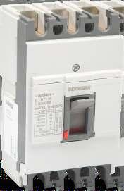
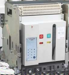
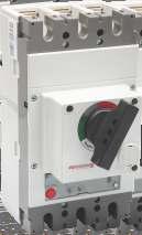
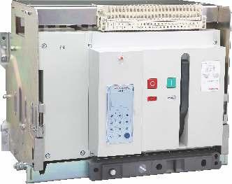
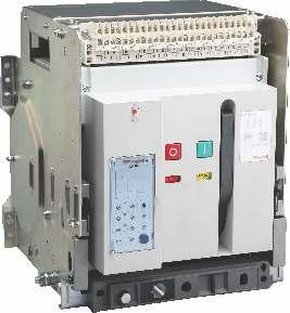
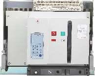
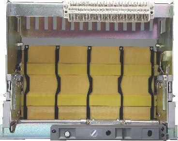
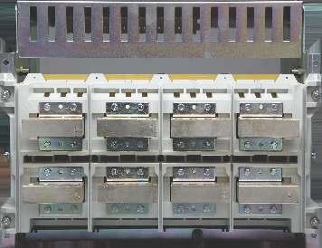
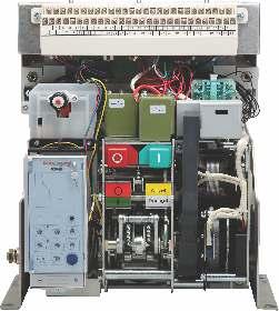
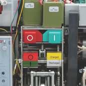
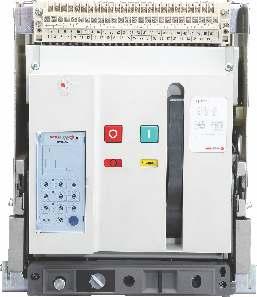
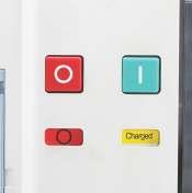
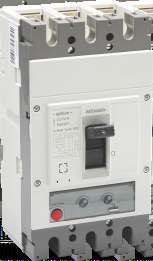
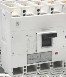
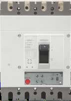
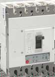
17 Optibreak B1 & B2 50/60 Hz Ue Icu [v] [ka] h 4i 1. Open / close Indication 2. Charge and Discharge Indicator 3. Release the reset button 4. Laser Nameplate 4b 4a 4e B1- M-3P In=2000A Icw(1s)=65kA Ics=100%Icu Uimp=12kV Ui=1000V IEC/EN Category-B 4k 4j 4g 4f 4d 4c 4 4a Product Code 4b Frame Rating 4c Selectivity category 4d Standard Compliance 4e Rated current 4f Rated insulation voltage 4g Rated impulse withstand voltage 4h Rated operating voltage 4i Rated ultimate short circuit breaking capacity 4j Rated service short circuit breaking capacity 4k Rated short time withstand current 50/60 Hz I1-M-3P Ie=2000A Ue [v] 415 Icw(1s)=65kA Icm[415V]=143kA Uimp=12kV Ui=1000V IEC/EN Category AC-23A AUT RESET 4 MAN Dust Cover (optional) 6. key Lock (optional) Location(knockout) 7. Pad Lock in Isolate Position 8. Rack in Handle insertion hole 9. Draw out position indicator 10. Rack in handle storage 11. Earthing Terminals 12. Phase barriers 13. Manual Charging Handle 14. ON Button 15. OFF Button Fixed Draw Out
18 Product Function and Characteristics: B1 & B2 Air Circuit Breakers Frame Inm A Optibreak B Optibreak B Rated current In A Poles 3/4 3/4 Rating of N-Pole 100% In 100% In Rated Operating voltage Ue AC 415V/AC 690V AC 415V/AC 690V Rated insulation voltage Ui 1000V 1000V Ratedimpulse withstand voltage Uimp 12KV 12KV Pollution Degree Grade-3 Mounting Fixed Drawer Rated ultimate short-circuit breaking capacityicu( ) ka L M M AC 415V 50/60Hz AC 690V 50/60Hz Rated Service short-circuit breaking capacityics( ) ka AC 415V 50/60Hz AC 690V 50/60Hz Rated short time withstand current Icw (1s)kA AC 415V 50/60Hz AC 690V 50/60Hz Utilization category B B Protection unit PU LSI( Ir,Ii,Isd) LSIG( Ir,Ii,Isd,Ig) Suitable For Isolation Standards compliant IEC Operating Life Mechanical life Electrical life Dimensions WxDxH(mm) Fixed Drawer 3P 4P 3P 4P 362x323x x323x x421x x421x x323x x323x x421x x421x432 Weight (Kg) Fixed Drawer 3P 4P 3P 4P
19 Product Function and Characteristics: B3 Air Circuit Breakers Frame Inm A Optibreak B Rated current In Poles Rating of N-Pole A 3200 & 4000A 3/4 100% In Rated Operating voltage Ue Rated insulation voltage Ui Ratedimpulse withstand voltage Uimp Pollution Degree Mounting Rated ultimate short-circuit breaking capacityicu( ) ka AC 415V 50/60Hz AC 690V 50/60Hz Rated Service short-circuit breaking capacityics( ) ka AC 415V 50/60Hz AC 690V 50/60Hz Rated short time withstand current Icw (1s)kA AC 415V 50/60Hz AC 690V 50/60Hz Utilization category Fixed Drawer AC 415V/AC 690V 1000V 12KV Grade-3 H B Protection unit PU LSI( Ir,Ii,Isd) LSIG( Ir,Ii,Isd,Ig) Suitable For Isolation Standards compliant IEC Operating Life Mechanical life Electrical life Dimensions WxDxH(mm) Fixed Drawer 3P 4P 3P 4P Weight (Kg) Fixed Drawer 3P 4P 3P 4P 4000A- 66 kg, below- 55kg 4000A- 80 kg, below- 68kg 4000A- 131 kg, below- 120kg 4000A- 160 kg, below- 148kg 18
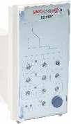
20 Accessories LSI protection LSIG protection Use the adjustment knob to select the folowing settings: Long delay overload protection: lr Over delay protection operation time: tr Short circuit short delay protection: l sd Short delay action time: tsd Instantaneous short circuit protection: li Neutral line protection: N Long delay overload protection: l r Over delay protection operation time: tr Short circuit short delay protection: l sd Short delay action time: tsd Instantaneous short circuit protection: l i Ground-fault protection : l g Ground-fault protection time: tg Neutral line protection: N Cat. Ref. Cat. Ref LSI protection Ir=0.4-1 In Adjustable tr= s Adjustable(6Ir) Isd= Ir Adjustable tsd= s Adjustable Ii= In-Icw Adjustable LSIg protection Ir=0.4-1 In Adjustable tr= s Adjustable(6Ir) Isd= Ir Adjustable tsd= s Adjustable Ii= In-Icw Adjustable Ig=o In Adjustable / can be turned off tg= s Adjustable 19
21 Protection Unit (PU)- Tripping Curve Ir=Long time setting current Tr=Long time delay Isd=Short circuit short time delay setting current Tsd=Short circuit short time delay setting time Ii=Instantaneous intervention setting current Isd=1,5Ir(±20%) Tsd=1000ms Isd=10Ir(±20%) Tsd=0ms If short-circuit current is higher than lcw value or li is setted at lcw position,tripping time is equal to 30ms. 20
22 Protection Unit (PU)- Tripping Curve t Ground fault tripping characteristic Ig=Ground Fault setting Current +20% tg=ground Fault Time delay +20% Protection Unit (PU)- Energy Curve Pass-through specific energy characteristic Estimated short circuit symmetrical current(rms value) Pass-through specific energy 21
23 Details of Accessories mm Max Mechanical interlock The components should be installed on the right side plate of the draw-out breaker. There are two type of component: the lever type and the wirerope type. The lever type is useable for the vertical installation referring to the picture a. The wirerope type is usable for the vertical or horizontal installation referring to picture b. Picture a When one breaker is closed, the another breaker can not be closed. The components should be installed by the customer and the type of the components should be specified. (2m)Max Delivery method: optional (Customer to mention references during order booking) R.> Picture b U1 U2 Mechanical interlock type number of the power U1 U2 the probably C o case of the o c breakers o o interlocking two breakers refer to the left diagram three breakers refer to the below diagram U1 U2 U3 number of the power the probably case of the breakers interlocking U1 U2 U3 C o o o C o C o C o o o 22
24 processing unit Power module charge Wiring Diagram SB1 - Shunt Push Button (arranged by customer) SB2 - UVR Push Button (arranged by customer) SB3 - Closing Coil Push Button (arranged by customer) SB4 - Motor Push Button (arranged by customer) SA - Motor Limit switch 1 & 2 - PUS Power supply input 12V DC Regulated through or ,4,5 - Fault Signal contact output (4=Common, 3=NC & 5=NO), Capacity: AC250V 16A. 6,7 - NO Aux Contact for ACB close indication, Capacity: AC250V 16A. 8,9 - NC Aux Contact for ACB open indication, Capacity: AC250V 16A. 18,19,20 - Not in Use. XT - Secondary isolating Contact circuit 23 & 24-3P ACB, external N phase Current Transformer port. (optional) J - Relay normally open remote control circuit breaker 27 & 28 - Undervoltage release connection. (optional) F - Shunt release X - Closing coil Q - Undervoltage ( instantaneous or delay) release 29,30 - Shunt Release connection. (optional) 31,32 - Closing Release connection. (optional) W - Breaker auxiliary contacts, 6NO + 6NC FU - Fuse M - Charging Motor Z - Protection Unit (Intelligent controller). 33,34 - Motor Charging connection. (optional) (Advance charging) 34,35 - Motor charging indicator. 36,51-6 NO/NC auxiliary contact for the Draw-out ACB. (40 to 51 change over contact) 36,55-6 NO/NC auxiliary contact for the Fixed ACB. (All are potential free contact) Protection Unit (PU) auxiliary contacts Closing Coil Shunt Release Charging indicator Charging Motor UV Release Power Supply N R Y B Fault close open Control Power Supply intelligent controller Fu AC415V AC220V, DC110V, DC220V Power Supply Note : 1. If Voltage Q, F X M & PU is different, connect separate supply 2. Dash line wiring diagram to be done by user external N phase 23
25 Dimensions & Mounting Optibreak B1/I1 - Fixed Type 413 (4 poles) 318 (3 poles) 292 C cabinet door N 340 (3 poles) (4 poles) a (longer busbar 353) mounting dimensions 4ol 12 In(A) mm a N direction C o15 l horizontal connection (normal type) N horizontal connection( longer busbar type) 24
26 a 402 Dimensions & Mounting Optibreak B2/I2 - Fixed Type 493 (4 poles) 378 (3 Poles) 352 B cabinet door N 400 (3 poles) (4 poles) ( longer busbar 368) mounting dimensions 4ol12 In(A) a direction B N ol horizontal connection (normal type) 86 o l N horizontal connection (longer busbar type) 25
27 Dimensions & Mounting Optibreak B1/I1 - Draw-out Type 430 (4 poles) 335 (3poles) C cabinet door N a (3 poles) 470 (4 poles) 421 (longer busbar 444) (connected position) 467 (longer busbar 490) (isolated position) mounting dimensions ol mm In(A) x17 ol (3 poles) 360 (4 poles) N direction C ol horizontal connection (normal type) N horizontal connection (longer busbar type) 26
28 Dimensions & Mounting Optibreak B2/I2 - Draw-out Type 510 (4 poles) 395 (3 poles) B cabinet door N 70 a C (3 poles) 450 (4 poles) 421 (longer busbar 484) (connected position 467 (longer busbar 530) (isolated position) mounting dimensions 33 ol In(A) a x17 o l (3 poles) 440 (4 poles) direction B o l N horizontal connection (normal type) N ol horizontal connection ( longer busbar type) 27
29 Dimensions & Mounting Door frame dimensions a 156 a xoI 5 b b breaker bottom draw-out 11xol 5 type a b B1/ I B2/ I
30 Air Circuit Breaker Type Breaking capacity Frame Rating 3P 4P Fixed 50kA B Fixed 50kA B Fixed 50kA B Fixed 50kA B Fixed 50kA B Fixed 50kA B Fixed 50kA B Type Breaking capacity Frame Rating 3P 4P D/O 50kA B D/O 50kA B D/O 50kA B D/O 50kA B D/O 50kA B D/O 50kA B D/O 50kA B Type Breaking capacity Frame Rating 3P 4P Fixed 65kA B Fixed 65kA B Fixed 65kA B Fixed 65kA B Fixed 65kA B Fixed 65kA B Fixed 65kA B Fixed 65kA B Fixed 65kA B

31 Air Circuit Breaker Type Breaking capacity Frame Rating 3P 4P D/O 65kA B D/O 65kA B D/O 65kA B D/O 65kA B D/O 65kA B D/O 65kA B D/O 65kA B D/O 65kA B D/O 65kA B Type Breaking capacity Frame Rating 3P 4P Fixed 85kA B Fixed 85kA B Type Breaking capacity Frame Rating 3P 4P D/O 85kA B D/O 85kA B

32 Trip Free Switch Type Breaking capacity Frame Rating 3P 4P Fixed 65kA I Fixed 65kA I Fixed 65kA I Fixed 65kA I Fixed 65kA I Fixed 85kA I Fixed 85kA I Type Breaking capacity Frame Rating 3P 4P D/O 65kA I D/O 65kA I D/O 65kA I D/O 65kA I D/O 65kA I D/O 85kA I D/O 85kA I Accessories Product Frame Cat Ref. Release LSI Release LSIg Product Frame Cat Ref. Auxiliary contact
33 Accessories Product Frame Cat Ref. Shunt trip 230 V AC Shunt trip 415 V AC Shunt trip 110 V DC Shunt trip 220 V DC Product Frame Cat Ref. Undervoltage 230VAC B1, B2 & B Undervoltage 415VAC B1, B2 & B Undervoltage 230VAC(0.3 ~ 5s) B1, B2 & B Undervoltage 415VAC(0.3 ~ 5s) B1, B2 & B Product Frame Cat Ref. Closing coil 230 V AC Closing coil 415 V AC Closing coil 110 V DC Closing coil 220 V DC Product Frame Cat Ref. Motor Operator 230VAC/220VDC B Motor Operator 415VAC B Motor Operator 110VDC B Product Frame Cat Ref. Motor Operator 230VAC/220VDC B2 & B Motor Operator 415VAC B2 & B Motor Operator110VDC B2 & B
34 Accessories Product Frame Cat Ref. Ext Neutral CT B1& B Product Frame Cat Ref. Vertical terminal 3P till 1000A Vertical terminal 4P till 1000A Vertical terminal 3P till 2000A Vertical terminal 4P till 2000A Vertical terminal 3P 3200A Fixed Vertical terminal 4P 3200A Fixed Vertical terminal 3P 3200A D/O Vertical terminal 4P 3200A D/O Product Frame Cat Ref. Phase Seperator3P Fixed Phase Seperator3P DO Phase Seperator4P Fixed Phase Seperator4P DO Product Frame Cat Ref. MIL- LeverFixed MIL- LeverDO MIL- CableFixed MIL- CableDO
35 Accessories Product Frame Cat Ref. Key-Lock1L + 1k Key-Lock2L + 1k Key-Lock3L + 1k Key-Lock3L + 2k Key-Lock5L + 3k Product Frame Cat Ref. Door interlock B1,B Product Frame Cat Ref. Door frame fixed B Door frame fixed B Door frame D/O B Door frame D/O B Product Frame Cat Ref. Dust cover B1,B Product Frame Cat Ref. Power module 415V B1,B Power module 230V B1,B
36
37
38
39 2.1= Elec. LSI & 2.2 = Elec. LSIG
40
41 16 ka 25 ka 36 ka 50 ka 16 ka 25 ka 36 ka 50 ka


42
43
44 Technical Characteristics - MCCB Time current characteristics O Time current tripping characteristics at ambient temperature 40 C Frame 1 - In (16A - 125A) I - load current ; Ir - the maximum value of the current setpoint thermal release. Current Rating You are a breaker is determined by the rated current thermal release ; 1 - working area of the "hot" state TE Pilaf release ( in working condition ) ; 2 - area of work from the "cold" state thermal release The multiplicity of the load current to the rated current of the circuit breaker 43
45 Technical Characteristics - MCCB Data limitations of current Frame 1 - In (16A - 125A) Limitation of shock value Short- current contiguity (actual maximum value) in the Depending on the current value of the expected direct fault current 44
46 Technical Characteristics - MCCB Limitations of energy curves Frame 1 - In (16A - 125A) Specific heat ( A2s ), ie energy, released during a short circuit in the conduction arrestor 1-ohm, depending from the rms value of the prospective current short circuit 45
47 Technical Characteristics - MCCB Time current characteristics Frame 2 - In (160A - 250A) I - load current ; Ir - the maximum value of the current setpoint thermal release. Rated current breaker depends on the bench current heat release ; 1 - working area of the "hot" state TE Pilaf release ( in working condition ) ; 2 - area of work from the "cold" state thermal release The multiplicity of the load current to the rated current of the circuit breaker 46
48 Technical Characteristics - MCCB Data limitations of current Frame 2 - In (160A - 250A) Limited impact the value of a short current circuit (the actual maximum value of ) depending on the current values of expected short-circuit current 47
49 Technical Characteristics - MCCB Limitations of energy curves Frame 2 - In (160A - 250A) Specific heat ( A2s ), ie energy, released during a short circuit in the conduction arrestor 1-ohm, depending from the rms value of the prospective current short circuit 48
50 Technical Characteristics - MCCB Time current characteristics Frame 3 - In (160A - 250A) I - load current ; Ir - the maximum value of the current setpoint thermal release. Rated current breaker depends on the bench current heat release ; 1 - working area of the "hot" state TE Pilaf release ( in working condition ) ; 2 - area of work from the "cold" state thermal release The multiplicity of the load current to the rated current of the circuit breaker 49
51 Technical Characteristics - MCCB Data limitations of current Frame 3 - In (160A - 250A) Limited impact the value of a short current circuit (the actual maximum value of ) depending on the current values of expected short-circuit current 50
52 Technical Characteristics - MCCB Limitations of energy curves Frame 3 - In (160A - 250A) Specific heat ( A2s ), ie energy, released during a short circuit in the conduction arrestor 1-ohm, depending from the rms value of the prospective current short circuit 51
53 Technical Characteristics - MCCB Frame 4 - In (315A - 630A) Performance data for Frame F4 Current limitation curves F4 F4 F4 52
54 Technical Characteristics - MCCB Frame 4 - In (315A - 630A) Performance data for Frame F4 (S - Sg) 2 53
55 Technical Characteristics - MCCB Frame 4 - In (315A - 630A) Performance data (earth fault) Sg Thermal stress limitation curves F4 F4 F4 54
56 Technical Characteristics - MCCB Performance data for Frame F5 Frame 5 - In (800A A) Current limitation curves F5 F5 F5 55
57 Technical Characteristics - MCCB Frame 5 - In (800A A) Thermal stress limitation curves F5 F5 F5 F5 F5 F5 56
58 Technical Table Devices Optium 1.0 F1 Optium 1.0 F2 Mounting On plate Breaking capacity 380/415V 16kA 25kA 25kA 16kA 25kA 36kA 220/240V Breaking capacity %Icu 50% 50% 50% 50% 50% 50% Characteristics of use Nominal frequency Maximum rated operating voltage Category of use 50Hz 690 V A Thermal magnetic adjustment Thermal Magnetic FIXED FIXED Electronic protection adjustment Maximum cable cross-section Rigid cable 2.5 to 16 mm 10 to 50 mm 35 to 50 mm 35 to 150 mm Flexible cable 2.5 to 10 mm 10 to 50 mm 35 to 50 mm 35 to 120 mm Copper bar and lug width 17mm 17mm 17mm 25mm Tightening torque 3 Nm 6 Nm 6 Nm 13 Nm Nominal current at 40 degree In (A) Phase N Magnetic threshold Fixed In (A) Phase N Endurance Electrical Mechanical
59 Technical Table Devices Optium 1.0 F3 Optium 1.0 F4 Mounting On plate Breaking capacity 380/415V 50kA 36kA 50kA 220/240V Breaking capacity %Icu 50% 50% 50% Characteristics of use Nominal frequency Maximum rated operating voltage Category of use 50Hz 690 V A Thermal magnetic adjustment Thermal Magnetic FIXED FIXED Electronic protection adjustment Maximum cable cross-section Rigid cable 2.5 to 150 mm 300 mm or 2 x 240 mm Flexible cable 2.5 to 120 mm 240 mm or 2 x 185 mm Copper bar and lug width 25 mm Tightening torque 7 Nm10 Nm 15 Nm Nominal current at 40 degree In (A) to 630 A Phase N Magnetic threshold Fixed In (A) Phase N Endurance Electrical Mechanical
60 Technical Table Devices Optium 1.0 F5 Optium 2.0 F1 Mounting On plate Breaking capacity 380/415V 50kA 16kA 25kA 220/240V Breaking capacity %Icu 50% 100% 100% Characteristics of use Nominal frequency Maximum rated operating voltage Category of use 50Hz 690 V A Thermal magnetic adjustment Thermal FIXED 0.8 to 1 In Magnetic FIXED 5 to 10 In Electronic protection adjustment Maximum cable cross-section Rigid cable 2 or 4 x 240 mm 2.5 to 16 mm 10 to 50 mm 35 to 50 mm Flexible cable 2 or 4 x 185 mm 2.5 to 10 mm 10 to 35 mm 35 to 50 mm Copper bar and lug width 50 mm 17mm 17 mm 17 mm Tightening torque 20 Nm 3 Nm 6 Nm 6 Nm Nominal current at 40 degree In (A) 800 A 16 to 125A Phase N Magnetic threshold Fixed Adjustable In (A) Phase N Endurance Electrical Mechanical
61 Technical Table Devices Optium 2.0 F2 Optium 2.0 F3 Optium 2.0 F4 Optium 2.0 F5 Mounting On plate Breaking capacity 380/415V 16kA 25kA 36kA 50kA 25kA 36kA 50kA 36kA 50kA 220/240V Breaking capacity %Icu 100% 100% 100% 100% 100% 100% 100% 100% 100% Characteristics of use Nominal frequency Maximum rated operating voltage Category of use 50Hz 690 V A Thermal magnetic adjustment Thermal Magnetic 0.8 to 1 In 5 to 10 In Electronic protection adjustment Maximum cable cross-section Rigid cable 35 to 150 mm 2.5 to 150 mm 300 mm or 2 x 240 mm 2 or 4 x 240 mm Flexible cable 35 to 120 mm 2.5 to 120 mm 240 mm or 2 x 185 mm 2 or 4 x 185 mm Copper bar and lug width 25 mm 25 mm 32 mm 50 mm Tightening torque 13 Nm 7 nm / 10 nm 15 Nm 20 Nm Nominal current at 40 degree In (A) 160 to 250 A Refer same as 315 to 630 A 800 to 1250A Phase Optium 1.0 F N Magnetic threshold Adjustable In (A) Phase N Endurance Electrical Mechanical
62 Technical Table Devices Optium 2.1 F3 Optium 2.1 F4 Optium 2.1 F5 Optium 2.2 F3 Optium 2.2 F4 Optium 2.2 F5 Mounting On plate Breaking capacity 380/415V 36kA 50kA 36kA 50kA 36kA 50kA 36kA 50kA 36kA 50kA 36kA 50kA 220/240V Breaking capacity %Icu 100% 100% 100% 100% 100% 100% 100% 100% 100% 100% 100% 100% Characteristics of use Nominal frequency 50Hz Maximum rated operating voltage 690 V Category of use A A:In 630A-B:In 200 to 400A B A A:In 630A-B:In 200 to 400A B Thermal magnetic adjustment Thermal Magnetic Electronic protection adjustment Ir : 0,4 to 1 In Isd : 1,5 to 10 Ir Ir = x In tr = 3-30 s Isd = Ir tsd (I=K) = ms tsd(i2t=k) = ms Ir = x In tr = 3-30 s Isd = Ir tsd (I=K) = ms tsd(i2t=k) = ms Ir : 0,4 to 1 In Isd : 1,5 to 10 Ir Ir = x In tr = 3-30 s Isd = Ir tsd (I=K) = ms tsd(i2t=k) = ms Ig = x In tg = s Ir = x In tr = 3-30 s Isd = Ir tsd (I=K) = ms tsd(i2t=k) = ms Ig = x In tg = s" Maximum cable cross-section Rigid cable 2.5 to 150 mm 300 mm or 2 x 240 mm 2 or 4 x 240 mm 2.5 to 150 mm 300 mm or 2 x 240 mm 2 or 4 x 240 mm Flexible cable 2.5 to 120 mm 240 mm or 2 x 185 mm 2 or 4 x 185 mm 2.5 to 120 mm 240 mm or 2 x 185 mm 2 or 4 x 185 mm Copper bar and lug width 25 mm 32 mm 50 mm 25 mm 32 mm 50 mm Tightening torque 7Nm /10 Nm 15 Nm 20 Nm 7Nm /10 Nm 15 Nm 20 Nm Nominal current at 40 degree In (A) Phase Please refer same as Optium 1.0 F3 400 to 630 A 400 to 630 A 800 to 1250 A 800 to 1250 A Please refer same as Optium 1.0 F3 400 to 630 A 400 to 630 A 800 to 1250 A 800 to 1250 A N % of phase value % of phase value % of phase value % of phase value Magnetic threshold In (A) Phase N Adjustable Endurance Electrical Mechanical
63 Dimensional Drawings Optium F1 Overall and Mounting Dimensions 3P 4P Dimensions with spreader Terminals MAX Rating Spreader Thickness A Dimensions with Rotary Handle-Direct 161 Dimensions with Rotary Handle-Vari-Depth Min Max mm ~2 (R)
64 92 Dimensional Drawings Optium F2 Overall and Mounting Dimensions 3P P Dimensions with spreader Terminals Rating Spreader Thickness A 4mm Dimensions with Rotary Handle-Direct Dimensions with Rotary Handle-Vari-Depth 60 Min Max ~2 (R)
65 Dimensional Drawings Optium F3 Overall and Mounting Dimensions 3P P Dimensions with spreader Terminals 110 MAX Rating Spreader Thickness A 4mm Dimensions with Rotary Handle-Direct Dimensions with Rotary Handle-Vari-Depth Min Max ~2 (R)
66 Dimensional Drawings Optium F4 Overall and Mounting Dimensions 3P P min Door Cut min max max. 15 max M Dimensions with spreader Terminals M5 2.5 max. 15 max Rating Spreader Thickness 630A 10mm Dimensions with Rotary Handle-Direct Dimensions with Rotary Handle-Vari-Depth Min Max ~ 2 (R)
67 Dimensional Drawings Optium F5 Overall and Mounting Dimensions 3P Y P 70 Y min. X M Y M10 Dimensions with spreader Terminals Rating Spreader Thickness 800/10000A 10mm 1250A 12mm Dimensions with Rotary Handle-Direct Dimensions with Rotary Handle-Vari-Depth Mounting with flexible seal max. 0.8/ min. (1) max. X M max. 66
68 Optium 1.0 (Fixed TM Range) Ics =50% Icu as per IEC II Suitable for isolation Class II front face Fixed Overload & fixed short circuit setting Frame Breaking capacity Rating 3P 4P F1 16kA F1 16kA F1 16kA F1 16kA F1 16kA F1 16kA F1 16kA F1 16kA F1 16kA Frame Breaking capacity Rating 3P 4P F1 25kA F1 25kA F1 25kA F1 25kA F1 25kA F1 25kA F1 25kA F1 25kA F1 25kA Frame Breaking capacity Rating 3P 4P F1 36kA F1 36kA F1 36kA F1 36kA F1 36kA F1 36kA F1 36kA F1 36kA F1 36kA
69 Frame Breaking capacity Rating 3P 4P F3 50kA F3 50kA F3 50kA F3 50kA F3 50kA F3 50kA F3 50kA F3 50kA F3 50kA Frame Breaking capacity Rating 3P 4P F2 16kA F2 16kA F2 16kA F2 25kA F2 25kA F2 25kA F2 36kA F2 36kA F2 36kA Frame Breaking capacity Rating 3P 4P F3 50kA F3 50kA F3 50kA Frame Breaking capacity Rating 3P 4P F4 36kA F4 36kA F4 36kA F4 36kA
70 Frame Breaking capacity Rating 3P 4P F4 50kA F4 50kA F4 50kA F4 50kA Frame Breaking capacity Rating 3P 4P F5 50kA Optium 2.0 (Adjustable TM Range) Ics =100% Icu as per IEC II Suitable for isolation Adjustable Short Circuit Setting Isd =(5-10)xIn Class II front face Adjustable Overload Setting Ir =(0.8 to 1.0)xIn Frame Breaking capacity Rating 3P 4P F1 16kA F1 16kA F1 16kA F1 16kA F1 16kA F1 16kA F1 16kA F1 16kA Frame Breaking capacity Rating 3P 4P F1 25kA F1 25kA F1 25kA F1 25kA F1 25kA F1 25kA F1 25kA F1 25kA
71 Frame Breaking capacity Rating 3P 4P F3 36kA F3 36kA F3 36kA F3 36kA F3 36kA F3 36kA F3 36kA F3 36kA F3 36kA Frame Breaking capacity Rating 3P 4P F3 50kA F3 50kA F3 50kA F3 50kA F3 50kA F3 50kA F3 50kA F3 50kA F3 50kA Frame Breaking capacity Rating 3P 4P F2 16kA F2 16kA F2 16kA F2 25kA F2 25kA F2 25kA F3 36kA F3 36kA F3 36kA
72 Frame Breaking capacity Rating 3P 4P F3 50kA F3 50kA F3 50kA Frame Breaking capacity Rating 3P 4P F4 25kA F4 25kA F4 36kA F4 36kA F4 36kA F4 36kA F4 50kA F4 50kA F4 50kA F4 50kA Frame Breaking capacity Rating 3P 4P F5 36kA F5 36kA F5 36kA F5 50kA F5 50kA F5 50kA
73 Optium 2.1 (Electronic Range) Ics =100% Icu as per IEC II Suitable for isolation Adjustable Overload Setting Ir = x In Class II front face Transparent cover for trip unit as standard Adjustable Short circuit Curent Setting Isd = x Ir Frame Breaking capacity Rating 3P 4P F3 36kA F3 36kA F3 36kA F3 36kA F3 50kA F3 50kA F3 50kA F3 50kA Optium 2.1 (Electronic Range) Ics =100% Icu as per IEC II Suitable for isolation Adjustable Neutral pole protection N,N/2 & Off for 4 pole MCCB Adjustable Overload Setting Ir = x In ; Tr = 3-30 sec Class II front face Transparent cover for trip unit as standard Innovative front indication LED's(Ready, Overload pre-alarm & Overload) Adjustable Short circuit Curent Setting Isd = Ir ; Tsd (I=K) = ms; Tsd (I2t=K) = ms Frame Breaking capacity Rating 3P 4P F4 36kA F4 36kA F4 50kA F4 50kA Frame Breaking capacity Rating 3P 4P F5 36kA F5 36kA F5 50kA F5 50kA

74 Optium 2.2 (Electronic Range) Ics =100% Icu as per IEC II Suitable for isolation Adjustable Overload Setting Ir = x In Ground fault Setting:- Ig = x In Class II front face Transparent cover for trip unit as standard Adjustable Short circuit Curent Setting Isd = x Ir Frame Breaking capacity Rating 3P 4P F3 36kA F3 36kA F3 36kA F3 36kA F3 50kA F3 50kA F3 50kA F3 50kA Optium 2.2 Ics =100% Icu as per IEC II Suitable for isolation Adjustable Neutral pole protection N,N/2 & Off for 4 pole MCCB Adjustable Overload Setting Ir = x In ; Tr = 3-30 sec Ground fault Setting:- Ig = x In ; Tg = s Class II front face Transparent cover for trip unit as standard Innovative front indication LED's(Ready, Overload pre-alarm & Overload) Adjustable Short circuit Curent Setting Isd = Ir ; Tsd (I=K) = ms; Tsd (I2t=K) = ms Frame Breaking capacity Rating 3P 4P F4 36kA F4 36kA F4 50kA F4 50kA Frame Breaking capacity Rating 3P 4P F5 36kA F5 36kA F5 50kA F5 50kA
75 Optium Accessories Product Frame Cat Ref. Auxiliary contact F1 F2 F Auxiliary contact F4-F Alarm Contact F1 F2 F Alarm Contact F4-F Product Frame Cat Ref. "Shunt trip 24 V AC/DC" F1 F2 F "Shunt trip 110 V AC/DC" F1 F2 F "Shunt trip 230 V AC/DC" F1 F2 F "Shunt trip 415 V AC/DC" F1 F2 F "Shunt trip 24 V AC/DC" F4 F "Shunt trip 110 V AC/DC" F4 F "Shunt trip 230 V AC/DC" F4 F "Shunt trip 415 V AC/DC" F4 F Product Frame Cat Ref. "Undervoltage 24 V DC" F1 F2 F "Undervoltage 110V AC" F1 F2 F "Undervoltage 230V AC" F1 F2 F "Undervoltage 415V AC" F1 F2 F "Undervoltage 24 V DC" F4 F "Undervoltage 110V AC" F4 F "Undervoltage 230V AC" F4 F "Undervoltage 415V AC" F4 F

76 Optium Accessories Product Frame Cat Ref. Rotary Handle Direct F Rotary Handle vary-depth F Rotary Handle Direct F2 F Rotary Handle vary-depth F2 F Rotary Handle Direct F Rotary Handle vary-depth F Rotary Handle Direct F Rotary Handle vary-depth F Product Frame Cat Ref. Ronis lock Direct RH F1 F2 F Ronis lock Vary-Depth RH F1 F2 F Ronis lock Vary-Depth RH F Ronis lock Vary-Depth RH F Product Frame Cat Ref. Padlock Off position F1 F2 F Padlock Off position F Padlock Off position F Product Frame Cat Ref. Phase insulators 3P F1 F Phase insulators 3P F Phase insulators 3P F Phase insulators 3P F Phase insulators 4P F1 F Phase insulators 4P F Phase insulators 4P F Phase insulators 4P F
77 Optium Accessories Product Frame Cat Ref. Terminal cover 3P F Terminal cover 3P F Terminal cover 4P F Terminal cover 4P F Terminal shield 3P F Terminal shield 4P F Product Frame Cat Ref. Spreaders 3P F Spreaders 4P F Spreaders 3P F2 F Spreaders 4P F2 F Spreaders 3P F Spreaders 4P F Spreaders 3P 800/1000A F Spreaders 4P 800/1000A F Spreaders 3P 1250A F Spreaders 4P 1250A F Product Frame Cat Ref. Cages 3P upto 50A F Cages 4P upto 50A F Cages 3P 63 to 100A F Cages 4P 63 to 100A F Cages 3P 125A F Cages 4P 125A F Cages 3P F Cages 4P F Cages 3P F Cages 4P F Cages 3P F Cages 4P F Cages 3P F Cages 4P F
78
79

80
81
82
83
84
85 Mini Contactor Technical Table CONTACTOR TYPE AC CONTACTOR 9A 12A STANDARD No. of Poles IEC/EN P, 4P No. of contacts Power Auxiliary 3NO 1NO 3NO 1NC 4NO 2NO+2NC - - Rated conventional Thermal Current (Ith) A 20 Rated operational voltage (Ue) V 690 Rated insulation voltage (Ui) V 690 Rated impulse withstand voltage (Uimp) Rated frequency kv Hz 6 50/60 Rated operational current AC3 (380V/400V) A 9 12 AC4 (380V/400V) A Rated operational power in AC-3 category 220/230/240V kw /400V /690V Rated making capacity A Rated breaking capacity 380V A V A Short circuit protection gg fuse A 20 Short circuit withstand (Ir) ka 1 Electrical Life AC3 (X10000) AC4 2 2 Mechanical life in Millions 10 Operating frequency AC3 (Electrical) Cycles/Hr 1200 AC4 (Electrical) Cycles/Hr 300 Mechanical Cycles/Hr
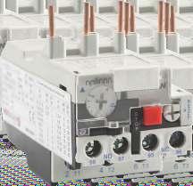
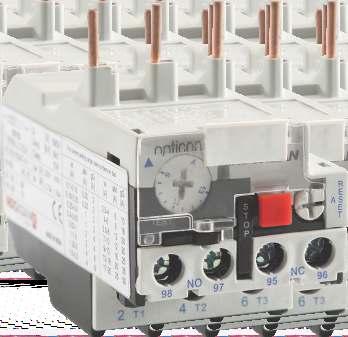
86 Thermal Overload Relay - Mini Contactor Technical Data Ÿ Standard IEC/EN Ÿ Number of connecting pin 5 Ÿ Rated operational voltage Ue (V) up to 690 Ÿ Rated insulation voltage Ui (V) 690 Ÿ Rated impulse withstand voltage Uimp (kv) 6 Ÿ Rated current range In (A) , , , , , , , , ,5.5-8,8-11.5,10-14 Ÿ Signalling Trip indicator Ÿ Tightening torque(n m) 0.8 Ÿ Mounting Directly under the contactor Ÿ Aux contacts Rated Current - AC15 220V 2.73A - AC15 380V 1.58A - DC13 220V 0.2A Rated Current (A) Reference codes Accessories Technical Data Ÿ Number of auxiliary contact: 2, 4 Ÿ Mounting type: Front Ÿ Conventional heating current (A) 10 Ÿ Rated operational voltage Ue (V) Up to 690 Ÿ Rated insulation voltage Ui (V) 690 Ÿ Conventional thermal current Ith (A) 10 Ÿ Control Rating AC-15: 360VA DC-13: 33W No. of Contacts 2NO 1NO+1NC Reference codes NC NO NO+1NC NO+2NC NO+3NC NC
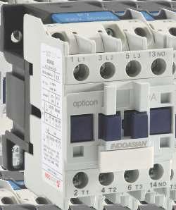
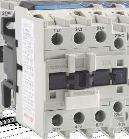
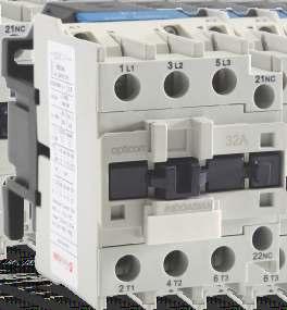
87 Power Contactor (from 9A to 95A) Technical Table CONTACTOR TYPE AC DC 9A 12A 18A 25A 32A 40A 50A 65A 80A 95A STANDARD IEC/EN No. of Poles 3, 4 3, 4 3 3, 4 3 3, 4 3, 4 3, 4 3, 4 3, 4 Rated conventional Thermal Current (Ith) A Rated operational voltage (Ue) V Up to 690 Rated insulation voltage (Ui) V 690 Rated impulse withstand voltage (Uimp) kv 8 Rated frequency Hz 50/60 Rated operational current 380V/400V AC3 A AC4 A V AC3 A AC4 A V AC1 A Rated operational power in AC-3 category 220/230/240V kw /400V /690V Rated making capacity Rated breaking capacity A A 10 X Ie for AC3 or 12 X Ie for AC4 8 X Ie for AC3 or 10 X Ie for AC4 Short circuit protection gg fuse A Short circuit withstand (Ir) ka Electrical Life AC3 ( X 1000) AC4 ( X 1000) Mechanical life ( in Millions) Operating Frequency AC3 cycles/hr AC4 cycles/hr Mechanical cycles/hr Coil operating range AC & DC Pick-up (85 % % ) Us Drop-out (20 % - 75 %) Us Coil Consumption AC Startup VA Holding VA Power W 1.8~ ~ ~2.8 3~4 3~4 6~10 6~10 6~10 6~10 6~10 DC Power W
88 Power Contactor (from 115A to 630A) Technical Table CONTACTOR TYPE AC CONTACTOR 115A 150A 185A 225A 265A 330A 400A 500A 630A STANDARD IEC/EN No. of Poles 3, 4 3, 4 3, 4 3, , 4 3, 4 3, 4 Rated conventional Thermal Current (Ith) A Rated operational voltage (Ue) V 1000 Rated insulation voltage (Ui) V 1000 Rated impulse withstand voltage (Uimp) kv 8 Rated frequency Hz 50/60 Rated operational current Ac3 A Ac1 A /230/240V kw Rated operational power in AC3 category 380/400V kw /690V kw Rated making capacity A 10 X Ie for Ac3 or 12 X Ie for AC4 Rated breaking capacity A 8 X Ie for Ac3 or 10 X Ie for AC4 Short circuit protection A Short circuit withstand current (Ir) ka Electrical life 6 AC3 (X 10 ) Mechanical life 6 (X 10 ) Operating frequency Electrical -AC3 Cycles / Hr Mechanical Cycles / Hr Coil operating range AC & DC Pick - up (85 % ~ 110 % ) Us Drop - out (20 % ~ 75 % ) Us 87
89 Thermal Overload Relay (for 9A to 95A) Technical Data Ÿ Standard IEC/EN Ÿ Tripping Class 10A Ÿ Rated operational voltage Ue (V) up to 690 Ÿ Rated insulation voltage Ui (V) 690 Ÿ Rated impulse withstand voltage Uimp (kv) 6 Ÿ Rated current range In (A) , 23-36, Ÿ Signalling Trip indicator Ÿ Mounting Directly under the contactor Ÿ Aux contacts Rated Current - AC15 230V 2.73A - AC15 400V 1.58A - DC13 220V 0.2A Rated Current Reference Code For Use With Contactors as per AC3 ratings) Rated Current Reference Code For Use With Contactors as per AC3 ratings) A A 12A 18A 25A A 50A 65A 80A 95A
90 Thermal Overload Relay (from 30A to 630A) Technical Data Ÿ Ÿ Ÿ Ÿ Ÿ Ÿ Standard Tripping Class Rated operational voltage Ue (V) Rated insulation voltage Ui (V) Rated impulse withstand voltage Uimp (kv) Rated current range In (A) IEC/EN A , 48-80, , , , Rated Current Reference Code For Use With Contactors as per AC3 ratings) A 150A 185A A 265A 330A 400A 500A A 500A 630A 89
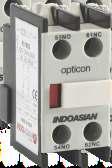
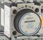
91 Accessories For Power Contactor Technical Data Add-on Auxiliary Blocks Ÿ Standard IEC/EN Ÿ Number of Auxiliary Contacts 2,4 Ÿ Mounting Type Front, Side Ÿ Conventional heating current: 10A Ÿ Rated operational voltage Up to 690V Ÿ Rated Insulation voltage 690V Ÿ Uimp 6kV Ÿ Operating Frequency: 50/60Hz Ÿ Control Rating: - AC VA - DC-13 33W Ÿ Short Circuit protection (gg fuse) 10A ADD-ON AUXILIARY BLOCKS Mounting Contact Configuration Ref.Codes Front 2NO Front 1NO+1NC Front 2NC Front 4NO Front 3NO+1NC Front 2NO+2NC Front 1NO+3NC Front 4NC Side 1NO+1NC Time Delay Blocks Ÿ Standard IEC/EN Ÿ Number of Auxiliary Contacts 2 Ÿ Mounting Type Front Ÿ Time delay type Making time delay Breaking time delay Ÿ Ranges s/0.1-30s/10-180s Ÿ Reset time During time delay period (ms) 150 After time delay period (ms) 50 Ÿ Conventional heating current: 10A Ÿ Rated operational voltage Up to 690V Ÿ Rated Insulation voltage 690V Ÿ Uimp 6kV Ÿ Operating Frequency: 50/60Hz TIME DELAY BLOCKS Type of Time Delay Time Delay Range Ref. Codes On Delay 0.1-3s On Delay s On Delay s Off Delay 0.1-3s Off Delay s Off Delay s
92 Control Relay Technical Table Contactor Type Contact Configuration 4NO, 3NO+1NC, 2NO+2NC AC DC 24V, 48V, 110V, 230V, 415V 24V and 48V Thermal current Ith A 10 Ue V 690 Ui V 690 Uimp kv 6 Operating limits Pick-up Drop-out V V (75~115) % Us (20~55) % Us Coil Consumption AC In rush Holding VA VA 30 / 4 25 / 3.0 Operating limits Coil Consumption DC Pick-up Drop-out In rush / Holding V V W (75~115) % Us (10~20) % Us 3.2 Average time Us Mechanical Life Operating Frequency AC DC Closing NO Opening NC Closing NO ms ms ms 12~21 7~17 18~25 Opening NC ms 11~17 In Millions 20 cycles cycles/hr
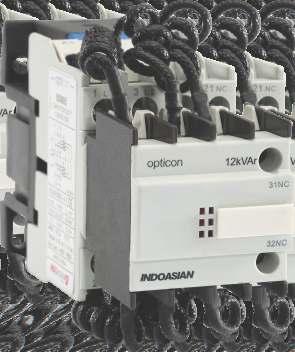
93 Capacitor Duty Contactors Technical Table Model 12 kvar 16 kvar 20 kvar 25 kvar 30 kvar 37 kvar 45 kvar 50kVAr Standard IEC/EN Rated Current 415V A Capacity Duty (AC-6b) 220/230V AC kvar /415V AC /690V AC Rated Insulation Voltage Ui V 690 Rated Operational Voltage Ue V 690 Rated Frequency Hz 50 / 60 Restrained Surge Capacity 20Ie Mechanical Life (X1000 ) Electrical Life (X1000) Operating Frequency Cycles/hr Operation Range Pick-up: (85%~110%) Us ; Drop-out: (20%~75%) Us Coil Power Start-Up VA Holding Auxiliary Contact type 2NO 2NO+1NC Tightening Torque Nm Rating Aux. Contact Configuration Reference Codes 230V AC 415 V AC 12 kvar 2NO kvar 2NO kvar 2NO kvar 2NO+1NC kvar 2NO+1NC kvar 2NO+1NC kvar 2NO+1NC kvar 2NO+1NC
94 Technical Characterstics Thermal Overload Relay - Mini Contactor Tripping Curve Thermal Overload Relay - Mini Contactor (from 0.11A to 14A) Time 2h 1h 20 min 1h 40min 20min 10min 6min 4min 2min 1min 40s 20s 10s 6s 4s 2s 1 2 1s 1 1,2 1, X setting current(lr) 1 Setting : at lower end of scale 2 Setting : at upper end of scale 93
95 Technical Characteristics - Thermal Overload Relay (for Power Contactors) Action characterisitics for thermal relay Average operating time related to multiples of the current setting (Class 10A) Thermal Overload Relay (from 0.1A to 93A) Time 2h 1h 20 min 1h 40min 20min Balanced 3-phase operation, from cold state 10min 6min 4min 2min 1min 40s 20s 10s 6s 4s 2s 1s 1 1,2 1, X setting current(lr) 1 Setting : at lower end of scale Setting : at upper end of scale Balanced operation with 2 phases only, from cold state Time 2h 1h 20 min 1h 40min 20min 10min 6min 4min 2min 1min 40s 20s 10s 6s 4s 2s 1s 1 1,2 1, X setting current(lr) 94
96 Technical Characteristics Thermal Overload Relay (for Power Contactors) Tripping Curve Thermal Overload Relay (from 0.1A to 93A) 1. Equilibrium running, 3 phase, start from cold state 2. Equilibrium running, 2 phase, start from cold state 3. Equilibrium running, 3 phase, after long period of setting current (hot state) Class 10A Hours Minutes S econds X times of current setting value
97 Technical Characteristics Thermal Overload Relay (for Power Contactor) Tripping Curve Thermal Overload Relay (from 30A to 630A) Time 2h 1h 40mm 20mm 10mm 4mm 2mm 1mm 40s 20s 10s 4s 2s 1s 0.8s X current setting (Ir) 96
98 Dimensional Drawings Mini Contactor 4XΦ4 unit in mm Type 9A-12A A B C D E
99 Dimensional Drawings AC Power Contactor (from 9A to 95A) 9A to 32A unit in mm D(A1)/E(A2) C A Ф B b a 40A to 95A D(A1)/E(A2) Ф B b a C A Type A max B max C max D max E max a b Φ 09A~12A /35 50/60 2-Φ4.5 18A /35 50/60 2-Φ4.5 3P 25A 32A Φ4.5 2-Φ4.5 40A~65A /110 3-Φ6.5 80A~95A /110 3-Φ6.5 09A~12A /35 50/60 2-Φ4.5 4P 25A 40A~65A / /110 2-Φ4.5 3-Φ6.5 80A~95A / /110 3-Φ6.5 98
100 Dimensional Drawings DC Power Contactor (from 9A to 95A) 09A to 32A unit in mm 2-Φd B max b b C max A max Φdx10 a 40A to 95A B max b 3-Φd C max a A max TYPE Outline dimensions A max B max C max Installation dimensions a b Φ 09A ~ 12A /35 50/60 2-Φ4.5 18A /35 50/60 2-Φ4.5 25A /60 2-Φ4.5 32A /60 2-Φ4.5 40A ~ 65A /110 3-Φ6.5 80A ~ 95A /110 3-Φ6.5 99
101 Dimensional Drawings Power Contactor (from 115A to 630A) 115A to 330A II S F115 M6X25 F150 M8X25 F185 M8X25 F225 M10X355 F265 M10X355 F330 M10X355 3xφ6.5 X1 II b b2 M b1 J J1 X1 II G1 II II Z G Y L Q P P Q1 c a f TYPE a b b1 b2 c f G G1 J J1 L M P Q Q1 S 1 Y Z 115A 3P 4P A 3P 4P A 3P 4P A 3P 4P A 3P 4P A 3P 4P f=minimum distance required for coil removal 100
102 A to 500A X1 56 X1 L c II II 209 b b2 S xM10x35 M Q P P Q1 a f 8xφ G G II II II II Power Contactor (from 115A to 630A) f=minimum distance required for coil removal 2P 3P 2P 3P 4P TYPE 400A 500A S Q Q P M L J G1 max G min G max G1* G1 min a b b c f G* P Dimensional Drawings
103 Dimensional Drawings Power Contactor (from 115A to 630A) 630A xM12x45 II 4xφ10.5 X1 II X II II 60.5 G J Q Q1 a 181 TYPE a G G min. G max. J1 Q Q1 630A 3P A 4P
104 Dimensional Drawings Thermal Overload Relay Upto 93A unit in mm 66max 78max NO NC NO NC T1 4T2 6T3 2T1 4T2 6T3 46max 94max 56max 94max SB1 SB NO NC T1 4T2 6T3 72max 117max 83max FU Contactor A A2 Relay U V W M Operating principle diagram of thermal overload relay 103
105 Dimensional Drawings Thermal Overload Relay (for contactors from 115A to 630A) 30A to 200A φ A to 630A xφ φ11 4xφ
106 Dimensional Drawings Capacitor Duty Contactors D 35 B b C 2 Φ d a A n - Φ D 35 b B C a A TYPE Outline dimensions Installation dimensions A B C D a b c 12kVAr /35 50/60 2 Φ kVAr /60 2 Φ kVAr /60 2 Φ kVAr /110 3 Φ kVAr /110 3 Φ kVAr /110 3 Φ kVAr /110 3 Φ kVAr /110 3 Φ
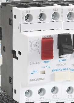
107 Motor Protection Circuit Breaker - MPCB Technical Table Type Frame 1 Standard IEC/EN , IEC/EN Utilization category According to IEC According to IEC A AC-3 Rated insulation voltage (Ui) V 690 Rated operational voltage (Ue) V 230 /240, 400/415, 440, 500, 660/690 Rated Impulse withstand voltage (Uimp) kv 8 Rated Range of current Setting A Rated current of release A Rated frequency Hz 50/60 Rated ultimate short circuit breaking capacity (Icu) 230/240 V ka 400/415 V ka 440 V ka /690 V ka Rated Service Short circuit breaking capacity (Ics) 230/240 V ka 400/415 V ka 440V ka /690 V ka Standard rated power of three phase motor 230/240 V kw 400 V kw V kw /690 V kw Current setting values for instantaneous release (Ir) A Electrical life (AC-3) Mechanical life Tightening Torque Nm
108 Motor Protection Circuit Breaker - MPCB Technical Table Type Frame 1 Frame 2 Standard IEC/EN , IEC/EN Utilization category According to IEC According to IEC A AC-3 Rated insulation voltage (Ui) V 690 Rated operational voltage (Ue) V 230 /240, 400/415, 440, 500, 660/690 Rated Impulse withstand voltage (Uimp) kv 8 Rated Range of current Setting A Rated current of release A Rated frequency Hz 50/60 Rated ultimate short circuit breaking capacity (Icu) 230/240 V ka 400/415 V ka 440 V ka /690 V ka Rated Service Short circuit breaking capacity (Ics) 230/240 V ka 400/415 V ka 440V ka /690 V ka Standard rated power of three phase motor 230/240 V kw 400 V kw V kw /690 V kw Current setting values for instantaneous release (Ir) A Electrical life (AC-3) Mechanical life Tightening Torque Nm
109 Technical Table - MPCB Accessories Shunt Release ITEM CODE RATED INSULATION VOLTAGE RANGE OF OPERATION FREQUENCY SPECIFICATION V 70%~110% Ue 50/60 Hz 110~115V 50Hz %~110% Ue 220~240V 50Hz %~ 110% Ue 380~400V 50Hz Under Voltage Release ITEM CODE RATED INSULATION VOLTAGE RANGE OF OPERATION FREQUENCY SPECIFICATION V 35%~70% Ue 50/60 Hz 110~115V 50Hz %~70% Ue 220~240V 50Hz %~ 70% Ue 380~400V 50Hz Auxiliary Contact ITEM CODE MOUNTING TYPE RATED INSULATION VOLTAGE CONVENTIONAL THERMAL CURRENT (Ith) AC15 240V (VA) CONTACT CONFIGURATION FRONT 250V 2.5A 120 1NO+1NC FRONT 2NO SIDE 690V 6A 720 1NO+1NC SIDE 2NO Auxiliary Alarm ITEM CODE RATED INSULATION VOLTAGE CONVENTIONAL THERMAL CURRENT (Ith) V 6A A A A 108
110 Technical Characteristics - MPCB Tripping Curve MPCB from 0.1A to 80A Average operating times at 20 C related to multiples of the setting current 1 3 poles from cold state 2 2 poles from cold state 3 3 poles from hot state Time(s) X the setting current (lr) 109
111 Dimensional Drawings Frame1 1 L1 3 L2 5 L3 0.16~0.25A OFF ON 91.3± ± ± ±0.28 Test 2 T1 4 T2 6 T3 44.5±0.8 8± ± ± ± ±0.95 Frame x Φ4 = =
 Coil Coil Coil Coil Coil Coil Coil Voltage Voltage Voltage Voltage Voltage Voltage Voltage 24V AC 24V DC 48V AC 48V DC 110V AC 230V AC 415V AC AC-3 1NO 9 850001")
 Coil Coil Coil Coil Coil Coil Coil Voltage Voltage Voltage Voltage Voltage Voltage")
 Coil Coil")
112 Power Contactors Conforms to IEC Range from 9A to 630A Utilisation category AC1, AC3 & AC4 Compact Dimensions saving panel space Rated operational voltage upto 690V Spares available for entire range Type Contact Rating(A) Coil Coil Coil Coil Coil Coil Coil Voltage Voltage Voltage Voltage Voltage Voltage Voltage 24V AC 24V DC 48V AC 48V DC 110V AC 230V AC 415V AC AC-3 1NO AC-3 1NO AC-3 1NO AC-3 1NO AC-3 1NO Type Contact Rating(A) Coil Coil Coil Coil Coil Coil Coil Voltage Voltage Voltage Voltage Voltage Voltage Voltage 24V AC 24V DC 48V AC 48V DC 110V AC 230V AC 415V AC AC-3 1NC AC-3 1NC AC-3 1NC AC-3 1NC AC-3 1NC Type Contact Rating(A) Coil Coil Coil Coil Coil Coil Coil Voltage Voltage Voltage Voltage Voltage Voltage Voltage 24V AC 24V DC 48V AC 48V DC 110V AC 230V AC 415V AC AC-3 1NO+1NC AC-3 1NO+1NC AC-3 1NO+1NC AC-3 1NO+1NC AC-3 1NO+1NC


113 Type Contact Rating(A) Coil Coil Coil Coil Coil Voltage Voltage Voltage Voltage Voltage 24V AC 48V AC 110V AC 230V AC 415V AC AC AC AC AC AC AC AC AC AC Type Contact Rating Rating Coil Coil Coil Coil Coil Coil Coil (A) (A) Voltage Voltage Voltage Voltage Voltage Voltage Voltage AC1 AC3 24V AC 24V DC 48V AC 48V DC 110V AC 230V AC 415V AC AC-1 4NO AC-1 4NO AC-1 4NO AC-1 4NO AC-1 4NO AC-1 4NO AC-1 4NO AC-1 4NO AC-1 4NO AC-1 4NO AC-1 4NO AC-1 4NO AC-1 4NO AC-1 4NO AC-1 4NO

114 Type Contact Rating Rating Coil Coil Coil Coil Coil Coil Coil (A) (A) Voltage Voltage Voltage Voltage Voltage Voltage Voltage AC1 AC3 24V AC 24V DC 48V AC 48V DC 110V AC 230V AC 415V AC AC-1 2NO+2NC AC-1 2NO+2NC AC-1 2NO+2NC AC-1 2NO+2NC AC-1 2NO+2NC AC-1 2NO+2NC AC-1 2NO+2NC AC-1 2NO+2NC AC-1 2NO+2NC AC-1 2NO+2NC AC-1 2NO+2NC AC-1 2NO+2NC AC-1 2NO+2NC AC-1 2NO+2NC AC-1 2NO+2NC Mini Contactors Conforms to IEC CE Certified Range from 9A to 12A Utilisation category AC1, AC3 & AC4 Rated operational voltage 690V Type Contact Rating(A) Coil Coil Coil Coil Coil Voltage Voltage Voltage Voltage Voltage 24V AC 48V AC 110V AC 230V AC 415V AC 3P 1NO P 1NO P 1NC P 1NC P 4NO P 2NO+2NC

 Coil Coil Coil")
115 Capacitor Duty Contactors Conforms to IEC CE Certified Range from 12kVAR to 50kVAR Utilisation category AC-6B Separate termination for damping resistors Type Contact Rating(A) Coil Coil Voltage Voltage 230V AC 415V AC 3P P P P P P P P Control Relay Conforms to IEC CE Certified Rated operational voltage 690V Available with AC & DC coil voltage Type Contact Rating(A) Coil Coil Coil Coil Voltage Voltage Voltage Voltage 24V AC 24V DC 48V AC 48V DC - 4NO NO + 1NC NO + 2NC Type Contact Rating(A) Coil Coil Coil Voltage Voltage Voltage 110V AC 230V AC 415V AC


116 Accessories Type Contact Rating(A) Cat Ref. Add on block for Power contactor - Front Mounted 2 NO Add on block for Power contactor - Front Mounted 1 NO + 1NC Add on block for Power contactor - Front Mounted 2 NC Add on block for Power contactor - Front Mounted 4 NO Add on block for Power contactor - Front Mounted 3 NO + 1 NC Add on block for Power contactor - Front Mounted 2 NO + 2 NC Add on block for Power contactor - Front Mounted 1 NO + 3 NC Add on block for Power contactor - Front Mounted 4 NC Add on block for Power contactor - Side Mounted 1 NO + 1NC Type Contact Rating(A) Cat Ref. Add on block for Mini contactor - Front Mounted 2 NO Add on block for Mini contactor - Front Mounted 1 NO + 1NC Add on block for Mini contactor - Front Mounted 2 NC Add on block for Mini contactor - Front Mounted 4 NO Add on block for Mini contactor - Front Mounted 3 NO + 1 NC Add on block for Mini contactor - Front Mounted 2 NO + 2 NC Add on block for Mini contactor - Front Mounted 1 NO + 3 NC Add on block for Mini contactor - Front Mounted 4 NC Type Contact Rating Cat Ref. Mechanical interlock - 9 A to 32 A Mechanical interlock - 40 A to 95 A Mechanical interlock A to 150 A Mechanical interlock A to 225 A Mechanical interlock A to 400 A Mechanical interlock A to 630 A


117 Type Contact Rating Cat Ref. Timer blocks On delay 0.1 to 3 sec Timer blocks On delay 0.1 to 30 sec Timer blocks On delay 10 to 180 sec Timer blocks Off delay 0.1 to 3 sec Timer blocks Off delay 0.1 to 30 sec Timer blocks Off delay 10 to 180 sec Type Contact Rating Cat Ref. Spare coil 24 V AC 9 to 18 A Spare coil 48 V AC 9 to 18 A Spare coil 110 V AC 9 to 18 A Spare coil 240 V AC 9 to 18 A Spare coil 415 V AC 9 to 18 A Spare coil 24 V DC 9 to 18 A Spare coil 48 V DC 9 to 18 A Spare coil 24 V AC 25 to 32 A Spare coil 48 V AC 25 to 32 A Spare coil 110 V AC 25 to 32 A Spare coil 240 V AC 25 to 32 A Spare coil 415 V AC 25 to 32 A Spare coil 24 V DC 25 to 32 A Spare coil 48 V DC 25 to 32 A Spare coil 24 V AC 40 to 95 A Spare coil 48 V AC 40 to 95 A Spare coil 110 V AC 40 to 95 A Spare coil 240 V AC 40 to 95 A Spare coil 415 V AC 40 to 95 A Spare coil 24 V DC 40 to 95 A Spare coil 48 V DC 40 to 95 A Spare coil 110 V AC 115 to 150 A Spare coil 240 V AC 115 to 150 A Spare coil 415 V AC 115 to 150 A

118 Type Contact Rating Cat Ref. Spare coil 110 V AC 185 to 225 A Spare coil 240 V AC 185 to 225 A Spare coil 415 V AC 185 to 225 A Spare coil 110 V AC 265 to 330 A Spare coil 240 V AC 265 to 330 A Spare coil 415 V AC 265 to 330 A Spare coil 110 V AC 400 A Spare coil 240 V AC 400 A Spare coil 415 V AC 400 A Spare coil 110 V AC 500 A Spare coil 240 V AC 500 A Spare coil 415 V AC 500 A Spare coil 110 V AC 630 A Spare coil 240 V AC 630 A Spare coil 415 V AC 630 A Thermal Overload Relay Conforms to IEC CE Certified Available range from 0.1A to 630A Trip class - 10A Direct and independent mounting Type Contact Rating Cat Ref. Thermal Overload Relay for Power Contactor A Thermal Overload Relay for Power Contactor A Thermal Overload Relay for Power Contactor A Thermal Overload Relay for Power Contactor A Thermal Overload Relay for Power Contactor A Thermal Overload Relay for Power Contactor A Thermal Overload Relay for Power Contactor A Thermal Overload Relay for Power Contactor A Thermal Overload Relay for Power Contactor A Thermal Overload Relay for Power Contactor A Thermal Overload Relay for Power Contactor A


119 Type Contact Rating Cat Ref. Thermal Overload Relay for Power Contactor A Thermal Overload Relay for Power Contactor A Thermal Overload Relay for Power Contactor A Thermal Overload Relay for Power Contactor A Thermal Overload Relay for Power Contactor A Thermal Overload Relay for Power Contactor A Thermal Overload Relay for Power Contactor A Thermal Overload Relay for Power Contactor A Thermal Overload Relay for Power Contactor A Thermal Overload Relay for Power Contactor A Thermal Overload Relay for Power Contactor A Thermal Overload Relay for Power Contactor A Thermal Overload Relay for Power Contactor A Thermal Overload Relay for Power Contactor A Thermal Overload Relay for Power Contactor A Thermal Overload Relay for Power Contactor A Thermal Overload Relay for Power Contactor A Thermal Overload Relay for Power Contactor A Thermal Overload Relay for Power Contactor A Thermal Overload Relay for Power Contactor A Type Contact Rating Cat Ref. Mounting Bracket - Relay Mounting Bracket - Relay Mounting Bracket - Relay Type Contact Rating Cat Ref. Thermal Overload Relay for Mini Contactor A Thermal Overload Relay for Mini Contactor A Thermal Overload Relay for Mini Contactor A Thermal Overload Relay for Mini Contactor A


120 Type Contact Rating Cat Ref. Thermal Overload Relay for Mini Contactor A Thermal Overload Relay for Mini Contactor A Thermal Overload Relay for Mini Contactor A Thermal Overload Relay for Mini Contactor A Thermal Overload Relay for Mini Contactor A Thermal Overload Relay for Mini Contactor A Thermal Overload Relay for Mini Contactor A Thermal Overload Relay for Mini Contactor A Motor Protection Circuit Breaker - MPCB Conforms to IEC CE Certified High breaking capacity upto 100A Wide range of accessories Thermal Protection Adj. Range Contact Rating(A) Cat Ref
DMX 3 -I 2500 switch disconnectors
 8704 LIMOGES Cedex Telephone : 0 0 87 87 Fax : 0 0 88 88 DMX 3 200 circuit breakers DMX 3 -I 200 switch disconnectors References: 0 28 20 / 21 / 22 / 23 / 24 / 2 / 2 / 30 / 31/ 32/ 33/ 34 / 3 / 3 / 40
DPX 1600 Electronic release
 87045 LIMOGES Cedex Phone :+33 05 55 06 87 87 Fax :+33 05 55 06 88 88 DPX 1600 CONTENTS PAGES 1. USE 1 2. RANGE 1 3. DIMENSIONS 1 3. DIMENSIONS (NEXT) 2 4. OVERVIEW 2 5. CONNECTION 2 6. ELECTRICAL AND
DPX Thermal magnetic and trip-free switches DPX 3 -I 250
 87045 LIMOGES Cedex Phone :+33 05 55 06 87 87 Fax :+33 05 55 06 88 88 DPX 3 250 Reference(s) : 420 205/ 207/ 208/209/ 215/ 217/ 218/ 219/ 235/ 237/ CONTENTS PAGES 1. USE 1 2. RANGE 1 3. DIMENSIONS 1 3.
DPX earth leakage DPX 3 -I earth leakage
 87045 LIMOGES Cedex Phone :+33 05 55 06 87 87 Fax :+33 05 55 06 88 88 DPX 3 250 + earth leakage Reference(s) : 420 225/ 227/ 228/229/ 255/ 257/ 258/ 259/ 285/ 287/ CONTENTS PAGES 1. USE 1 2. RANGE 1 3.
DPX Magnetic only
 87045 LIMOGES Cedex Phone :+33 5 55 06 87 87 Fax :+33 5 55 06 88 88 CONTENTS PAGES 1. USE 1 2. RANGE 1 3. DIMENSIONS 1 3. DIMENSIONS (NEXT) 2 4. ELECTRICAL AND MECHANICAL CHARACTERISTICS 3 5. CONFORMITY
cor Long Run Experience
 Moulded Case Circuit Breakers Moulded Case Circuit Breakers 16-1250A cor Long Run Experience cor Breaking capacity (according to IEC 947-2 at 415V) Icu 100 D160L D250L D400L D630L 70 60 DH800 50 35 30
DPX moulded case circuit breakers
 BREAKING AND PROTECTION DEVICES 10 / 2011 DPX moulded case circuit breakers DPX moulded case circuit breakers offer optimum solutions for the protection requirements of commercial and industrial installations.
DPX Thermal magnetic and trip-free switches DPX 3 -I 160
 87045 LIMOGES Cedex Phone :+33 05 55 06 87 87 Fax :+33 05 55 06 88 88 DPX 3 160 CONTENTS PAGES 1. USE 1 2. RANGE 1 3. DIMENSIONS 1 4. OVERVIEW 2 5. ELECTRICAL AND MECHANICAL CHARACTERISTICS 3 6. CONFORMITY
DPX Electronic + earth leakage
 87045 LIMOGES Cedex Phone :+33 5 55 06 87 87 Fax :+33 5 55 06 88 88 DPX 3 250 Electronic + earth leakage CONTENTS PAGES 1. USE 1 2. RANGE 1 3. DIMENSIONS 1 3. DIMENSIONS (NEXT) 2 4. ELECTRICAL AND MECHANICAL
DPX Electronic. Fiche technique : F01362EN/02 Mise à jour le : 15/12/2011 Créé le : 15/06/2011
 87045 LIMOGES Cedex Phone :+33 5 55 06 87 87 Fax :+33 5 55 06 88 88 DPX 3 250 Electronic Reference(s): 420 302/305/307/309/312/315/317/319/332/335/ CONTENTS PAGES 1. USE 1 2. RANGE 1 3. DIMENSIONS 1 3.
DPX 630 Electronic release
 87045 LIMOGES Cedex Phone :+33 05 55 06 87 87 Fax :+33 05 55 06 88 88 DPX 630 CONTENTS PAGES 1. USE 1 2. RANGE 1 3. DIMENSIONS 1 4. OVERVIEW 2 5. CONNECTION 2 6. ELECTRICAL AND MECHANICAL CHARACTERISTICS
DRX 125 Circuit breaker (not adjustable)
") 87045 LIMOGES Cedex Téléphone : 05 55 06 87 87 Télécopie : 05 55 06 88 88 272 20/21/22/23/24/25/26/27/55/56/57/58/59/60 INDEX PAGES 1. USE 1 2. RANGE 1 3. DIMENSIONS 1 3. DIMENSIONS (continuation) 2 4.
87045 LIMOGES Cedex Téléphone : 05 55 06 87 87 Télécopie : 05 55 06 88 88 272 20/21/22/23/24/25/26/27/55/56/57/58/59/60 INDEX PAGES 1. USE 1 2. RANGE 1 3. DIMENSIONS 1 3. DIMENSIONS (continuation) 2 4.
New DMX 3. Efficient protection up to A AIR CIRCUIT BREAKERS PRODUCT GUIDE
 New DMX 3 Efficient protection up to 4 000 A AIR CIRCUIT BREAKERS PRODUCT GUIDE NEW DMX 3 ACBs UP TO 4 000 A EFFICIENT PROTECTION AND CONTROL FOR ALL TYPE OF BUILDINGS 02 Electrical panel equipped with
Specification for 70mm pole pitch Air circuit breaker up to 1600 A
 Specification for 70mm pole pitch Air circuit breaker up to 1600 A Protective device for low voltage electrical installation Last update :2011-07-08-1 - Table of contents: 1 General...3 2 Compliance with
DRX 100 B/N/H Circuit breaker (not adjustable)
") 87045 LIMOGES Cedex Téléphone : 05 55 06 87 87 Télécopie : 05 55 06 88 88 INDEX PAGES 1. USE 1 2. RANGE 1 3. DIMENSIONS 1 3. DIMENSIONS (continuation) 2 4. MOUNTING 2 5. CABLING 3 6. ELECTRIC AND MECHANICAL
87045 LIMOGES Cedex Téléphone : 05 55 06 87 87 Télécopie : 05 55 06 88 88 INDEX PAGES 1. USE 1 2. RANGE 1 3. DIMENSIONS 1 3. DIMENSIONS (continuation) 2 4. MOUNTING 2 5. CABLING 3 6. ELECTRIC AND MECHANICAL
(p. 47) (p. 155) (p. 155)
 (p. 155) (p. 155)") 0 286 56 + 0 288 02 (p. 47) 0 286 74 + 0 288 02 (p. 155) 0 287 56 + 0 288 02 (p. 155) Dimensions see e-catalogue Elecical characteristics p. 162 Automatic air circuit breakers must be equipped with eleconic
0 286 56 + 0 288 02 (p. 47) 0 286 74 + 0 288 02 (p. 155) 0 287 56 + 0 288 02 (p. 155) Dimensions see e-catalogue Elecical characteristics p. 162 Automatic air circuit breakers must be equipped with eleconic
DRX 250 B/N/H Circuit breaker (not adjustable)
") 87045 LIMOGES Cedex Téléphone : 05 55 06 87 87 Télécopie : 05 55 06 88 88 References rences: /18/19/20/21/22/23/24/25/26/27/28/29/ 32/33 INDEX PAGES 1. USE 1 2. RANGE 1 3. DIMENSIONS 1 4. MOUNTING 2 5.
87045 LIMOGES Cedex Téléphone : 05 55 06 87 87 Télécopie : 05 55 06 88 88 References rences: /18/19/20/21/22/23/24/25/26/27/28/29/ 32/33 INDEX PAGES 1. USE 1 2. RANGE 1 3. DIMENSIONS 1 4. MOUNTING 2 5.
3 - Protection components Motor circuit-breakers
 Contents 0 - Protection components Motor circuit-breakers protection components for the motor protection Thermal-magnetic motor circuit-breakers Selection guide..............................................page
Page. Circuit-Breakers M4 2 for motor protection. Auxiliary contacts 3 Signalling switch Auxiliary releases
 Circuit Breakers M4 Page Circuit-Breakers M4 2 for motor protection Auxiliary contacts 3 Signalling switch Auxiliary releases Insulated 3-pole busbar system 4 Terminal block DIN-rail adapters 5 Busbar
Breaking and protection devices
 Power guide: A complete set of technical documentation Breaking and protection devices 01 Sustainable development 08 Protection against external disturbances 02 Power balance and choice of power supply
 15 16 MCCBs for Power Distribution Technical Specification Frame 100A 250A 250A 400A 400A 630A 800 / 1000 / 1250 Type C DN0-100 D DN1-250 N DN2-250 D N S H DN3B-400 DN3-400 D N D N S V DN3-630 DN4-1250
C 1. SPECTRONIC SP - Air circuit breakers. Summary. C2. General characteristics. C3. Fixed circuit breaker. C4. Withdrawable circuit breakers
 SPETRONI SP - Air circuit breakers Summary 2. General characteristics 3. Fixed circuit breaker 4. Withdrawable circuit breakers 5. haracteristics 6. RV23: protection and control unit 6. RV+ : protection
Vistop TM isolating switches 63 to 160A
 DX 3 - IS main switches 16 to 125A Vistop TM isolating switches 63 to 160A 225 15 225 18 4 064 00 4 064 59 Pack Cat. No. Main switches AC 22 A category as per EN607-3 Grey handle Accept 1 signalling auxiliary
Phase + Neutral, neutral on left side
 87045 LIMOGES Cedex Téléphone : 05 55 06 87 87 Télécopie : 05 55 06 88 88 DX 3 MCB 10000 A / 16 ka CONTENTS PAGE 1. Description, use...1 2. Range...1 3. Overall dimensions...1 4. Preparation - Connection...1
SIDERMAT Load break switches for power distribution from 250 to 1800 A with tripping function
 The solution for Load break switches sdmat_066_a cat > Main switchboard > Distribution panel > Motor load break unction SIDERMT 4 x 630 External front operation SIDERMT are manually operated 3 or 4 pole
AF40... AF96 3-pole contactors Technical data
 Main pole - Utilization characteristics according to IEC Standards IEC 60947- / 60947-4- and EN 60947- / 60947-4- Rated operational voltage Ue max. 690 V Rated frequency (without derating) 50 / 60 Hz Conventional
WORKSHOP SPECIFICATIONS
 WORKSHOP SPECIFICATIONS DPX 3 160 & 250 MOULDED CASE CIRCUIT BREAKERS THE GLOBAL SPECIALIST IN ELECTRICAL AND DIGITAL BUILDING INFRASTRUCTURES DPX 3 RANGE Not only do DPX³ 160 and DPX 3 250 MCCBs provide
DPX Thermal magnetic and trip-free switches DPX 3 -I 630
 87045 LIMOGES Cedex Phone :+33 05 55 06 87 87 Fax :+33 05 55 06 88 88 DPX 3 630 CONTENTS PAGES 1. USE 1 2. RANGE 1 3. DIMENSIONS 1 4. OVERVIEW 2 5. ELECTRICAL AND MECHANICAL CHARACTERISTICS 2 6. CONFORMITY
DPX 630 Thermal magnetic and trip-free switches DPX-I 630
 87045 LIMOGES Cedex Phone :+33 05 55 06 87 87 Fax :+33 05 55 06 88 88 DPX 630 CONTENTS PAGES 1. USE 1 2. RANGE 1 3. DIMENSIONS 1 4. OVERVIEW 2 5. CONNECTION 2 6. ELECTRICAL AND MECHANICAL CHARACTERISTICS
Phase + Neutral, neutral on right side
 87045 LIMOGES Cedex Telephone number: +33 5 55 06 87 87 Fax: +33 5 55 06 88 88 DX 3 MCB 6000 A / 10 ka Cat.. N (s): 4 074 67 / 68 / 69 / 70 / 71 / 72 / 73 / 74 / 75 / 76 / 77 / 78 / 79 ; 4 077 33 / 34
Moulded case circuit breakers
 Moulded case circuit breakers CONTENT Range 4 Protection Releases 5 Salient Features 8 Accessories, 4 Technical data 2 Time Current Characteristics 5 Overall Dimensions 7 SN4 SN3 SN2 SN 3 RANGE Moulded
Thermal magnetic and trip-free switches
 87045 LIMOGES Cedex Phone : 33 05 55 06 87 87 Fax : 33 05 55 06 88 88 DPX 3 1600 Reference(s : 422 250 /251/ 252/ 253/ 254/ 255 /256/ 262/263/ 264/ 265/ 266/ 267/268/ 269/ 270/ 271/ 272/ 273/ 278/ 287/
Prisma ipm Switchboard Air Circuit Breaker (ACB) Moulded-case Circuit Breaker (MCCB) Contactor Power meter
 Moulded-case Circuit Breaker (MCCB) Contactor Power meter") 3 Prisma ipm Switchboard Air Circuit Breaker (ACB) Moulded-case Circuit Breaker (MCCB) Contactor Power meter The easy choice for quality, value, and peace of mind Schneider Electric makes it an easy choice
3 Prisma ipm Switchboard Air Circuit Breaker (ACB) Moulded-case Circuit Breaker (MCCB) Contactor Power meter The easy choice for quality, value, and peace of mind Schneider Electric makes it an easy choice
DPX 160 Thermal magnetic and trip-free switches DPX-I 160
 87045 LIMOGES Cedex Phone : +33 05 55 06 87 87 FAX : +33 05 55 06 88 88 DPX 160 CONTENTS PAGES 1. USE 1 2. RANGE 1 3. DIMENSIONS 1 3. DIMENSIONS (NEXT) 2 4. OVERVIEW 2 5. CONNECTION 2 6. ELECTRICAL AND
, , PREPARATION - CONNECTION. Mounting:. On symmetrical EN rail or DIN 35 rail
 87045 LIMOGES Cedex Telephone number: +33 (0)5 55 06 87 87 Fax: +33 (0)5 55 06 88 88 DX 3 4500 A / 6 ka CONTENTS PAGES 1. Description, use...1 2. Range...1 3. Overall dimensions...1 4. Preparation - Connection...1
Manual Motor Starters. Meta-MEC
 Manual Motor Starters Meta-MEC Manual Motor Starters LS Meta-MEC Manual Motor Starters provide completed ranges up to 100A 45 mm 55 mm 32AF 2 2 45 mm 70 mm 63AF 100AF 3 3 Manual LS Meta-MEC Motor Starters
AF09... AF30 3-pole Contactors up to 25 HP / 600 VAC
 AF09... AF0 -pole Contactors up to 25 HP / 600 VAC Contactors and Overload Relays Overview.../0 AF09... AF0 -pole Contactors.../2 Main Technical Data.../8 Main Accessory Fitting Details.../2 Main Accessory.../24
CHINT. NM7 Moulded Case Circuit Breaker
 CHINT Moulded Case Circuit Breaker Moulded Case Circuit Breaker Application Product introduction Functions and characteristics Accessories Overall and dimension Specification selection and order Page
DNX 3 MCB 4500 A / 6 ka Phase + Neutral, neutral on left side
 87045 LIMOGES Cedex Telephone number: +33 (0)5 55 06 87 87 Fax: +33 (0)5 55 06 88 88 DNX 3 MCB 4500 A / 6 ka CONTENTS PAGE 1. Description, use... 1 2. Range... 1 3. Overall dimensions... 1 4. Preparation
Breakers and Switches. Tmax XT Moulded-case circuit-breakers Simply extraordinary
 Breakers and Switches Tmax XT Moulded-case circuit-breakers Simply extraordinary Tmax XT Simply extraordinary ABB is proud to present you the result of a long and intense research and development project:
GV2, GV3, and GV7 Manual Motor Starters, Controllers, and Protectors Standard Features
 Standard Features Table : Standard Features GV2ME GV2P GV3P GV7RE/GV7RS 0. to 32 A Up to 20 hp @ 460 V 0 SCCR @ 480 V Push Button Operator 0. to 30 A Up to 5 hp @ 460 V 50 SCCR @ 480 V Rotary Handle Operator
GJL 100 A Molded Case Circuit Breaker GJL 75 A Motor Circuit Protector
 GJL 100 A Molded Case Circuit Breaker GJL 75 A Motor Circuit Protector Catalog 0500CT9702R409 2009 Class 525/580 CONTENTS Description............................................. Page General Characteristics...................................
LEXIC Curv LIMOGES Cedex. Cats N (s) : /68/87/88, /48, /84/85, /76/77/95/96/97, /71/72 1.
 : /68/87/88, /48, /84/85, /76/77/95/96/97, /71/72 1.") 87045 LIMOGES Cedex Téléphone : 05 55 06 87 87 Télécopie : 05 55 06 88 88 LEXIC MCB s DX-H 80A, 100A, 125A Curv urves B and C CONTENTS PAGES 1. Description, use...1 2. Range...1 3. Overall dimensions...1
87045 LIMOGES Cedex Téléphone : 05 55 06 87 87 Télécopie : 05 55 06 88 88 LEXIC MCB s DX-H 80A, 100A, 125A Curv urves B and C CONTENTS PAGES 1. Description, use...1 2. Range...1 3. Overall dimensions...1
FUSOMAT Visible breaking and tripping fuse switches from 250 to 1250 A
 Fuse protection The solution for > Motor load break > Protection of industrial cabinet > Electrical distribution fusom_063_b_1_cat Strong points > Tripping upon overload > High breaking capacity > Improved
01 Spectra Plus - Introduction
 01 Spectra Plus - Introduction Standard features Conforming to IS13947-2/EN60947 2 Compact dimensions Available in 3P & 4P High performance microprocessor protection release Wide overload setting from
B115...B180 RF200 RFN200 B250...B400 RF400 RFN400
 Page -2 Page -4 Page -6 FOR BG SERIES MINI-CONTACTORS Type RF9, phase failure sensitive, manual resetting Type RFA9, phase failure sensitive, automatic resetting Type RFN9, non-phase failure sensitive,
Essential equipment for all your requirements
 NEW CTX CONTACTORS Essential equipment for all your requirements 9 A TO 310 A THREE-POLE INDUSTRIAL CONTACTORS CTX three-pole industrial contactors, a sense of family The new range of CTX contactors provides
Low Voltage. EasyPact CVS. Moulded-case circuit breakers from 16 to 100 A
 Low Voltage EasyPact CVS Moulded-case circuit breakers from 16 to 100 A Catalogue 2013 EasyPact CVS Contents Functions and characteristics A-1 Installation recommendations B-1 Dimensions and connection
Overview of Low voltage equipment - Moulded-case & Air circuit-breakers
 Overview of Low voltage equipment - Moulded-case & Air circuit-breakers Moulded-case circuit-breakers for distribution (1) R16 and R20 Icu = 16 ka @ 220/230 V (2) All the versions with Icu = 35 ka are
Memshield - ACB Ratings & Specifications
 Memshield Memshield - ACB Ratings & Specifications Rating and specifications Current rating, A List No Number of poles RATED CURRENT (A) [In] IEC, BS, VDE, AS Neutral pole ampere frame (A) RATED PRIMARY
DX³ 4-pole RCBO 6000 A/10 ka
 87045 LIMOGES Cedex Telephone number: +33 (0)5 55 06 87 87 Fax: +33 (0)5 55 06 88 88 DX³ 4-pole RCBO CONTENTS PAGE 1. Description, use... 1 2. Range... 1 3. Overall dimensions... 1 4. Preparation - Connection...
AF40... AF96 3-pole contactors 30 to 60 hp at 480 V AC AC / DC operated with 1 N.O. + 1 N.C. auxiliary contacts
 AF4... AF96 -pole contactors to 6 hp at 48 V AC AC / DC operated with N.O. N.C. auxiliary contacts Description AF4... AF96 contactors are mainly used for controlling -phase motors and power circuits up
Motor Protection Circuit Breakers
 Motor Protection Circuit Breakers About us Larsen & Toubro is a technologydriven USD 9.8 billion company that infuses engineering with imagination. The Company offers a wide range of advanced solutions
PRICE LIST THE GLOBAL SPECIALIST IN ELECTRICAL AND DIGITAL BUILDING INFRASTRUCTURES
 PRICE LIST THE GLOBAL SPECIALIST IN ELECTRICAL AND DIGITAL BUILDING INFRASTRUCTURES MAY 2018 Ui690V Uimp6kV 50 60Hz Ics=50%Icu Ue Icu [VAC] [ka] 220 240 125 380 415 10 440 460 10 480 550 7.5 600 5 NEMA-ABI
Circuit breakers and switch-disconnectors NT06 to NT16 and NW08 to NW63
 Functions and characteristics Circuit breakers and switch-disconnectors NT06 to NT16 and NW08 to NW63 NT and NW selection criteria Masterpact NT Masterpact NW NT06, NT08, NT10, NT12, NT16 NT06, NT08, NT10
Power protection solutions
 Power protection solutions DMX A.C.Bs UP TO 4000 A In high power installations, the role of the main enclosure is to: - House protection devices and provide for their connection - Provide management and
Protection components
 Presentation, characteristics Presentation 1 2 3 motor circuit-breakers are 3-pole thermal-magnetic circuit-breakers standards IEC 60947-2 and IEC 60947-4-1. Connection These circuit-breakers are designed
AF / AF12Z pole Contactors AC / DC Operated - with Screw Terminals
 Technical Datasheet 1SBC101404D0201 24/03/11-30-10-.. / Z-30-10-.. 3-pole Contactors AC / DC Operated - with Screw Terminals (Z) contactors are used for controlling power circuits up to 690 V AC and 220
DX³ RCCBs - ID 4P up to 100 A
 87045 LIMOGES Cedex Telephone number: +33 (0)5 55 06 87 87 Fax: +33 (0)5 55 06 88 88 DX³ s - ID CONTENTS PAGE 1. Description, use... 1 2. Range... 1 3. Overall dimensions... 1 4. Preparation - Connection...
RX 3 MCB 4500 A Phase + Neutral, neutral on left side
 87045 LIMOGES Cedex Téléphone : 05 55 06 87 87 Télécopie : 05 55 06 88 88 RX 3 MCB 4500 A CONTENTS PAGE 1. Description, use... 1 2. Range... 1 3. Overall dimensions... 1 4. Preparation - Connection...
Circuit-Breakers M4 166 for motor protection. Auxiliary contacts 167 Signalling switch Auxiliary releases
 Index Page Circuit-Breakers M4 166 for motor protection Auxiliary contacts 167 Signalling switch Auxiliary releases Insulated 3-pole busbar system 168 Terminal block DIN-rail adapters 169 Busbar adapters
Low voltage moulded case circuit breaker EB2
 Low voltage moulded case circuit breaker EB2 Product series description unit condition Model-type Number of poles Nominal current ratings Electrical characteristics Rated operational voltage Rated insulation
CTX 3 Control relays Cat. N (s) : /06/09..14/16/19..24/26/29
 : /06/09..14/16/19..24/26/29") 87045 LIMOGES Cedex Telephone: +33 5 55 06 87 87 FAX: +33 5 55 06 88 88 CTX 3 Control relays Cat. N (s) : 4 168 00..04/06/09..14/16/19..24/26/29 CONTENTS PAGES 1. Description - Use... 1 2. Range... 1 3.
87045 LIMOGES Cedex Telephone: +33 5 55 06 87 87 FAX: +33 5 55 06 88 88 CTX 3 Control relays Cat. N (s) : 4 168 00..04/06/09..14/16/19..24/26/29 CONTENTS PAGES 1. Description - Use... 1 2. Range... 1 3.
Low voltage Direct Current Network. Compact NSX DC PV. Circuit breakers and switch disconnectors for solar application.
 Low voltage Direct Current Network Compact NSX DC PV Circuit breakers and switch disconnectors for solar application Catalogue 2012 Compact NSX DC PV A complete DC offer for solar application from 80
DNX 3 MCB 4500 A / 6 ka Phase + Neutral, neutral on left side
 87045 LIMOGES Cedex Téléphone : 05 55 06 87 87 Télécopie : 05 55 06 88 88 DNX 3 MCB 4500 A / 6 ka CONTENTS PAGE 1. Description, use... 1 2. Range... 1 3. Overall dimensions... 1 4. Preparation - Connection...
AF09... AF30 3-pole Contactors up to 20 HP / 480 VAC
 AF0... AF0 -pole Contactors up to 20 HP / 480 VAC Contactors and Overload Relays Overview...2 AF0... AF0 -pole Contactors Ordering Details...4 Main Technical Data...20 DC Circuit switching...2 Main Accessory
Low voltage. Masterpact NT and NW. LV power circuit breakers and switch-disconnectors Draw-out Type & Fixed Type. Catalogue
 Low voltage Masterpact NT and NW LV power circuit breakers and switch-disconnectors Draw-out Type & Fixed Type Catalogue 2015 Functions and characteristics Circuit breakers and switch-disconnectors NT06
Index. Manual Motor Starters 1. Auxiliary Contact Blocks 1. Trip Alarm Auxiliary 1. Switch. Shunt Release 1. Under-voltage Release 2.
 Index Index Page Manual Motor Starters 1 Auxiliary Contact Blocks 1 Trip Alarm Auxiliary 1 Switch Shunt Release 1 Under-voltage Release 2 Accessories 2 Busbar Connectors 2 Enclosures 2 Leistung, kw C mv
Characteristics of LV circuit breakers Releases, tripping curves, and limitation
 Characteristics of LV circuit breakers Releases, tripping curves, and limitation Make, Withstand & Break Currents A circuit breaker is both a circuit-breaking device that can make, withstand and break
Latch for Contactors 4-pole see page 36. Ratings Rated Aux. Contacts Type Coil voltage 2) AC2 Current Built-in Additional 24 24V= DC 5
 AC2 Current Built-in Additional 24 24V= DC 5") 3-pole DC Operated Ratings Rated Aux. Contacts Type Coil voltage 1) AC2 Current Built-in Additional 24 24V= DC 5 AC3 see 48 60V= DC 6 380V AC1 page 34 110 110V= DC 7 400V 660V 220 220V= DC 8 415V 690V
3-pole DC Operated Ratings Rated Aux. Contacts Type Coil voltage 1) AC2 Current Built-in Additional 24 24V= DC 5 AC3 see 48 60V= DC 6 380V AC1 page 34 110 110V= DC 7 400V 660V 220 220V= DC 8 415V 690V
Ktec Contactors and thermal overloads
 Contactors and thermal overloads Techna KTEC series contactors provide a complete solution for your ac contactor requirements.the range carries TUV, UL & CSA certification, for use in Europe, North America
price list IN ELECTRICAL AND DIGITAL BUILDING INFRASTRUCTURES
 price list THE GLOBAL SPECIALIST IN ELECTRICAL AND DIGITAL BUILDING INFRASTRUCTURES APRIL 2014 P. 07 P. 08 DMX3 ACB from 630 A to 2500 A Fixed version Draw-out version P. 13 cat.a Ui690V Uimp6kV 50 60Hz
MULTI 9 System Catalog IEC Rated C60N/H/L Circuit Breakers
 IEC Rated C60N/H/L Circuit Breakers Standard Features Fast Closing Allows increased withstand to the high inrush currents of some loads Trip-free mechanism: Contacts cannot be held in the on position when
Industrial Contactors CTX 3 3P 185A - 800A
 87045 LIMOGES Cedex Telephone: +33 5 55 06 87 87 FAX: +33 5 55 06 88 88 Industrial Contactors CONTENTS PAGES 1. Description - Use... 1 2. Range... 1 3. Overall dimensions... 1 4. Installation - Connection...
Motor Protection Circuit Breakers 3VU13 and 3VU16
 Motor Protection Circuit Breakers 3VU13 and 3VU16 3VU13/3VU16 is suitable for use in fuseless motor feeders upto 11KW/22KW (25A/63A) respectively. 3VU motor protection circuit breakers are used for protection
22AF 40AF AF 150AF 225AF 400AF 800AF
 Contactors MC-Series UL508 E108780 Contactor 3 Pole Standards and Certifications UL508 IEC 60947-2 & IEC 60947-4-2 CSA C22.2 No.14 Features 8 Frame Sizes 1/2HP up to 600HP @ 480V AC Screw Terminals (Lug
Approved Standards. Motor Contactor. Main contactor. Accessoires. 21 Motor Contactor J7KN
 Motor Contactor Main contactor AC & DC operated Integrated auxiliary contacts Screw fixing and snap fitting (35 mm DIN rail) up to 45 kw Range from 4 to 110 kw (AC 3, 380/415V) Finger proof ( VBG 4) Accessoires
SD Series Non-Fused Load Switches
 SD Series Non-Fused Load Switches The SD1 and SD2 series of non-fused load switches are listed as Manual Motor Controllers and are designed for use in local motor isolation. The SD series of modular load
AF09... AF38 4-pole Contactors AC / DC Operated - with Screw Terminals
 AF09... AF38 4-pole Contactors AC / DC Operated - with Screw Terminals 25 to 55 A culus CE Application AF09... AF38 4-pole contactors are used for controlling power circuits up to 600 V AC and 240 V DC.
3VU13, 3VU16 Circuit-Breakers
 3VU3, 3VU6 Circuit-Breakers Description The 3VU3, 3VU6 circuit-breakers are compact circuit-breakers for currents up to 80 A which operate according to the current limiting principle. The devices are used
87045 LIMOGES Cedex. 2. PRODUCT RANGE (continued) 1. DESCRIPTION - USE. Breaking capacity : Symbol : Technology : 3. OVERALL DIMENSIONS
 1. DESCRIPTION - USE. Breaking capacity : Symbol : Technology : 3. OVERALL DIMENSIONS") 87045 LIMOGES Cedex Phone : + 33 5 55 06 87 87 Fax : + 33 5 55 06 88 88 R.C.B.O. DX 6000 A Phase + Neutral,, neutral on right side Cat. n (s) : 077 31 077 44-077 77 077 84 078 79 079 01-083 95 084 06 084
87045 LIMOGES Cedex Phone : + 33 5 55 06 87 87 Fax : + 33 5 55 06 88 88 R.C.B.O. DX 6000 A Phase + Neutral,, neutral on right side Cat. n (s) : 077 31 077 44-077 77 077 84 078 79 079 01-083 95 084 06 084
PRICE LIST THE GLOBAL SPECIALIST IN ELECTRICAL AND DIGITAL BUILDING INFRASTRUCTURES
 PRICE LIST THE GLOBAL SPECIALIST IN ELECTRICAL AND DIGITAL BUILDING INFRASTRUCTURES AUGUST 2017 P. 07 P. 08 DMX3 ACB from 630 A to 2500 A Fixed version Draw-out version P. 12 cat.a Ui690V Uimp6kV 50 60Hz
ME 07 Air Circuit Breakers. ME 07 - Air Circuit Breakers. Low Voltage. Low Voltage. Low Voltage
 Low Voltage ME 07 - Air Circuit Breakers ME 07 Air Circuit Breakers Low Voltage AEG Niederspannungstechnik GmbH & Co KG Berliner Platz 2-6 D-24534 Neumünster (Germany) Tel. +49/43211-0 Fax +49/43211-144
schneider-electric.com/sg K60 Circuit Breakers The affordable way to stay safe from electrocution and electrical overloads schneider-electric.
 K0 Circuit Breakers The affordable way to stay safe from electrocution and electrical overloads Overview K0 Circuit Breaker Technical Specification MCB RCCB K0 Circuit Breaker K0N K0H ID K Number of poles
Interchangeable Built-in Fixed thermal Adjustable thermal Magnetic Fixed Adjustable Adjustable Electronic RMS 7 LS LSI
 . Technical Data and Specifications Ratings Frames EG, JG and LG EG JG LG Maximum rated current (amperes) 15, 160 1 50 400, 630 Breaker type 3 B B E S S H H C E S H C U X E S H C U X of poles 1, 3, 4,
PRICE LIST THE GLOBAL SPECIALIST IN ELECTRICAL AND DIGITAL BUILDING INFRASTRUCTURES
 PRICE LIST THE GLOBAL SPECIALIST IN ELECTRICAL AND DIGITAL BUILDING INFRASTRUCTURES APRIL 2015 Ui690V Uimp6kV 50 60Hz Ics=50%Icu Ue Icu [VAC] [ka] 220 240 380 415 440 460 480 550 600 NEMA-ABI 240 (HIC)
Motor Protection Circuit Breaker
 Motor Protection Circuit Breaker Catalogue 2011 CONTENT Introduction...4 Features...4 Parts Identification...5 Technical information (MPCB)...5 Technical information (Aux. contact, Fault signalling contact)...6
DX³ RCBO 4500/6 ka Phase + Neutral, neutral on left
 87045 LIMOGES Cedex Telephone number: +33 5 55 06 87 87 Fax: +33 5 55 06 88 88 DX³ RCBO 4500/6 ka CONTENTS PAGE 1. Description, use... 1 2. Range... 1 3. Overall dimensions... 1 4. Preparation Connection...
Introduction. Standard Features. GV2, GV3, and GV7 Manual Motor Starters, Controllers, and Protectors Introduction
 Introduction Introduction Schneider Electric offers a complete line of products for the manual control and protection of motors. This catalog covers those devices designed to meet IEC standards for protection
D509E. Manual Motor - Starters
 D509E Manual Motor - Starters Index Page Manual Motors Starters 182 Auxilliary Contact Blocks 182 Trip Alarm Aux. Switch 182 Shunt Release 182 Under-voltage Release 183 Accessories 183 Busbar Connectors
Industrial contactors CTX-1
 87045 LIMOGES Cedex Telephone number: +33 5 55 06 87 87 Fax: +33 5 55 06 88 88 Industrial contactors /04/05/10/12/14/15/20/22/24/25/30/32/34/35/40/42/44/45 CONTENTS PAGE 1. Use... 1 2. Range... 1 3. Electrical
up to 63 A (1 module per pole)
") 87045 LIMOGES Cedex Telephone: +33 5 55 06 87 87 FAX: +33 5 55 06 88 88 Direct current MCB DX 3 16kA, up to 63 A (1 module per pole) CONTENTS PAGE 1. Description - Use... 1 2. Range... 1 3. Overall dimensions...
87045 LIMOGES Cedex Telephone: +33 5 55 06 87 87 FAX: +33 5 55 06 88 88 Direct current MCB DX 3 16kA, up to 63 A (1 module per pole) CONTENTS PAGE 1. Description - Use... 1 2. Range... 1 3. Overall dimensions...
(1,5 modules per pole)
") 87045 LIMOGES Cedex Telephone: +33 5 55 06 87 87 FAX: +33 5 55 06 88 88 DX 3 MCB 36kA, 80A CONTENTS PAGES 1. Description - Use... 1 2. Range... 1 3. Overall dimensions... 1 4. Preparation - Connection...
87045 LIMOGES Cedex Telephone: +33 5 55 06 87 87 FAX: +33 5 55 06 88 88 DX 3 MCB 36kA, 80A CONTENTS PAGES 1. Description - Use... 1 2. Range... 1 3. Overall dimensions... 1 4. Preparation - Connection...
Btdin-RS RCBO 2p Phase + Neutral, neutral on right
 Viale Borri 231, 21100 Varese - Italy RCBO 2p CONTENTS PAGE 1. Description, use... 1 2. Range... 1 3. Overall dimensions... 1 4. Preparation Connection... 1 5. General characteristics... 2 6. Compliance
Meta Solution. Contactors and Overload relays
 Meta Solution Contactors and Overload relays Meta Solution New generation of Contactors from LSIS Contactors and Overload Relays Metasol Contactors Designed to show superior technology: The Metasol series
NDM3 Series. Molded Case Circuit Breaker. Shanghai Liangxin Electrical CO., LTD.
 Shanghai Liangxin Electrical CO., LTD. - Liangxin Electrical - All rights reserved Address: No. 66 eng An Road, Pu Dong New District, Shanghai Post code: 07 Tel: 6--479 Fax: 6--5675966 E-mail: client@sh-liangxin.com
DCX-M. changeover switches ->CATALOGUE PAGES INSIDE THE GLOBAL SPECIALIST IN ELECTRICAL AND DIGITAL BUILDING INFRASTRUCTURES
 DCX-M changeover switches ->CATALOGUE PAGES INSIDE THE GLOBAL SPECIALIST IN ELECTRICAL AND DIGITAL BUILDING INFRASTRUCTURES FOR COMMERCIAL BUILDINGS AND DCX-M In = 63 A Quality & design CONFORM TO EN/IEC
Basic function. Rated current. Appropriate for three-phase motors of output 2) [kw] I n. = 400 V a.c. 2) Appropriate for three-phase motors
![Basic function. Rated current. Appropriate for three-phase motors of output 2) [kw] I n. = 400 V a.c. 2) Appropriate for three-phase motors](/thumbs/74/70162763.jpg "Basic function. Rated current. Appropriate for three-phase motors of output 2) [kw] I n. = 400 V a.c. 2) Appropriate for three-phase motors") MOTOR STARTERS SM Basic function Switching and protection of motors up to A Protection against short-circuit and protection against overload The device responds to phase failure The device is provided
MOTOR STARTERS SM Basic function Switching and protection of motors up to A Protection against short-circuit and protection against overload The device responds to phase failure The device is provided
Compact NR630. NR100F to NR630F
 Low voltage switchgear Compact NR NR100F NR630F The Compact NS range has revolutionised the world of moulded-case circuit breakers. For installations not requiring the high performance levels of the NS
For Info: Phone: Fax:
 Page -2 TWO POLES IEC rated current Ith: 20A (AC1) IEC operational power: 1.3kW (AC3 230V) Ideal for domestic applications. Page -2 THREE AND FOUR POLES IEC rated current Ith: 25A, 40A and 63A (AC1) IEC