Stepper Motor. Introduction...04 Quick Selection Of Motor...11
|
|
|
- Rose Harrington
- 6 years ago
- Views:
Transcription
1
2 Stepper Motor Introduction Quick Selection -phase Stepper Motors -phase Stepper Motors UStepper Motors onfigurations Introduction Quick Selection Of Motor -phase Stepper Motors Stepper Motors NEMA 8 ( mm)-phase 8-8 HY Series D NEMA( 8mm)-phase 8 - HS Series D NEMA( mm)-phase 8 - HY Series D NEMA( mm)-phase 9 - HA Series D NEMA7( mm)-phase 8-7HD Series D NEMA7( mm)-phase 9-7HA Series D 7 NEMA( mm)-phase 8 - HS Series D 8 NEMA( mm)-phase 8 - HS Power Plus Series D 9 NEMA( mm)-phase 8 - HS Series D NEMA( 8mm)-phase 8 - HD Series D NEMA( mm)-phase 8 - HS Series A NEMA( mm)-phase 8 - HS Series A NEMA( 8mm)-phase 8 - HD Series A NEMA( mm)-phase 8 - HS Series A IP Type Stepper Motors NEMA( mm)-phase 8 - HS Series D IP Type 7 NEMA( mm)-phase 8 - HS Series D IP Type 8 NEMA( 8mm)-phase 8 - HD Series D IP Type 9 Brake Type Stepper Motors NEMA7( mm)-phase 8-7HD Series D Brake Type NEMA( mm)-phase 8 - HS Series D Brake Type NEMA( mm)-phase 8 - HS Series D Brake Type NEMA( mm)-phase 8 - HS Series A Brake Type NEMA( 8mm)-phase 8 - HD Series D/A Brake Type Planetary Reducer Motors NEMA7( mm)-phase 8-7HD Series D Planetary Reducer Type NEMA( mm)-phase 8 - HS Series D Planetary Reducer Type 7 NEMA( mm)-phase 8 - HS Series D Planetary Reducer Type 8 NEMA( 8mm)-phase 8 - HD Series D Planetary Reducer Type 9 NEMA( 8mm)-phase 8 - HD Series A Planetary Reducer Type Encoder Type Stepper Motors NEMA7( mm)-phase 8-7HD Series D Encoder Type NEMA( mm)-phase 8 - HS Series D Encoder Type NEMA( mm)-phase 8 - HS Series D Encoder Type NEMA( 8mm)-phase 8 - HD Series D Encoder Type NEMA( 8mm)-phase 8 - HD Series A Encoder Type -phase Stepper Motors Stepper Motors NEMA7( mm)-phase - 7H Series D
3 ontents NEMA( mm)-phase - H Series D 7 Flange Demension 7 NEMA( mm)-phase - H Series D Flange Demension 8 NEMA( 8mm)-phase - H Series D 9 NEMA( 8mm)-phase - H Series A -phaseu Stepper Motors U Stepper Motors NEMA( mm)-phase 8 - HS U Series D NEMA( mm)-phase 8 - HS U Series D NEMA( 8mm)-phase 8 - HD U Series D NEMA( mm)-phase 8 - HS U Series A NEMA( mm)-phase 8 - HS U Series A NEMA( 8mm)-phase 8 - HD U Series A NEMA( mm)-phase 8 - HS U Series A 7 Power Plus Type U Stepper Motors NEMA( mm)-phase 8 - HS U Series D Power Plus8 IP Type U Stepper Motors NEMA( mm)-phase 8 - HS U Series D IP Type NEMA( mm)-phase 8 - HS U Series D IP Type NEMA( 8mm)-phase 8 - HD U Series D IP Type onfigurations Bearing ife & Shaft oading onfiguration Options Glossary onversion Factors 7 Introduction Quick Selection -phase Stepper Motors -phase Stepper Motors UStepper Motors onfigurations
4 Introduction of Stepping Motors What is Stepping Motor Introduction Quick Selection -phase Stepper Motors -phase Stepper Motors UStepper Motors onfigurations Stepping Motors provide precise position and speed control, without the need for feedback devices to sense position The operation of step motors is controlled through electrical pulses that the drive converts to current flowing through the windings of the motor As the current is switched the motor rotates in precise steps of a fixed angle The motor and drive constitutes a low cost control system that is precise and simple to construct Performance Features of MOONS Stepping Motors Accurate Position ontrol The number of control pulses defines the motor shaft position Position error is very small (less than /th of a degree), and non cumulative Precise Motor Speed Step motor running speed, is exactly determined by the frequency of the control pulses Because the speed is very precise and easy to control, step motors are often used where coordinated motion control is needed Forward & Reverse, Pause and Holding Function Motor torque and position control is effective throughout the entire speed range, including zero speed holding torque The zero speed holding torque locks the shaft at the desired position to hold the load in place ow Speed Operation Step motors produce a large amount of torque, and are easy to control, at low speeds This often eliminates the need for speed reduction gearboxes, reduces costs and saves space ong ife The brushless design of step motors leads to motors with a very long life Step motor life is usually determined by the life of the bearings
5 Basic Structure and Motor Operation Basic Structure Operating Principles In response to each individual control pulse and direction signal, the drive applies power to the motor windings to cause the rotor to take a step forward, a step in reverse, or lock in position For example, in a 8 degree two phase step motor: When both phases are energized with D current, the motor will stop rotating and hold in position The maximum torque the motor can hold in place with rated D current, is the rated holding torque If the current in one phase is reversed, the motor will move step (8 degrees) in a known direction If the current in the other phase had been reversed, the motor would move step (8 degrees) in the other direction As current is reversed in each phase in sequence, the motor continues to step in the desired direction These steps are very accurate For a 8 degree step motor, there are exactly steps in one revolution Two phase stepping motors are furnished with two types of windings: bipolar or unipolar In a bipolar motor there is one winding on each phase The motor moves in steps as the current in each winding is reversed This requires a drive with eight electronic switches In a unipolar motor there are two windings on each phase The two windings on each phase are connected in opposite directions Phase current is reversed by turning on alternate windings on the same phase This requires a drive with only four electronic switches Bipolar operation typically provides % more holding torque than unipolar, because % of the winding is energized in the bipolar arrangement + VD A B D phase step motor with bipolar driver + VD A B D phase step motor with unipolar driver Introduction Quick Selection -phase Stepper Motors -phase Stepper Motors UStepper Motors onfigurations
6 Technical Data and Terminology oad alculations Introduction Quick Selection -phase Stepper Motors -phase Stepper Motors UStepper Motors onfigurations A Torque load (Tf) Tf = G r G: weight r: radius B Inertia load (TJ) TJ = J dw/dt J = M (R +R ) / (Kg cm) M: mass R: outside radius R: inside radius dw/dt: angle acceleration Speed-Torque haracteristics The dynamic torque curve is an important aspect of stepping motor s output performance The followings are some keyword explanations A Working frequency point express the stepping motors rotational speed value at this point n = q Hz / ( D) n: rev/sec Hz: the frequency value at this point D: the subdividing value of motor driver q: the step angle of stepping moto Eg: 8 stepping motor, in the condition of I/ subdividing (each step 9 ) runs at Hz its speed is r/s B Start/Stop region: the region in which a stepping motor can be directly started or stopped Slew Range: the motor cannot be started directly in this area It must be started in the start/stop region first and then accelerated to this area In this area, the motor can not be directly stopped, either Otherwise this will lead to losing-step The motor must be decelerated back to the start/stop region before it can be stopped D Maximum starting frequency point at this point, the stepping motor can reach its maximum starting speed under unloaded condition E Maximum running frequency point at this point the stepping motor can reach its maximum running speed under an unloaded condition F Pull-in Torque: the maximum dynamic torque value that a stepping motor can load directly at the particular operating frequency point G Pull-out Torque: the maximum dynamic torque value that a stepping motor can load at the particular operating frequency point when the motor has been started Because of the inertia of rotation the Pull-Out Torque is always larger than the Pull-In Torque G r R R
7 alculate the Acceleration Torque How to accelerate or decelerate in the shortest time is the most important when the system s operating frequency point is in the slew range of the dynamic torque curve graph Tm It is shown by the following graph: the dynamic torque s performance of stepping motor will always keep a horizontal straight line in low speed But in high speed, the curve will slope A Accelerated Motion of Straight ine Motor s load value is known as T, it has to be accelerated from F to F in the shortest time (tr), what is the value of tr? () Generally TJ = 7%Tm () tr = 8 - J q (F-F)/(TJ-T) () F (t) = (F-F) t/tr + F, <t<tr B Exponential Acceleration () Generally TJ = 7%Tm, TJ = 7%Tm, T = %Tm () tr = F In [(TJ-T)/(TJ-T)] () F (t) = F [ e^(-t/f)] + F, <t<tr F = (T-TJ) (F-F)/(FJ-TJ) F = 8 - J q F/(TJ-T) Note: J is the torque inertia of motor rotor plus its load, q is the angle of each step, it equals to the step angle of stepping motor when motor runs in full step As for the control of deceleration, it can be realized by turning the accelerate pulse frequency above-mentioned Reduction of Vibration and Noise In a non-loading condition, stepping motors may appear to have vibration or even lose steps when the motor is running at or close to resonant frequency Solutions for these conditions A Have the motor operate outside of this speed range B By adopting the micro-step driving method, you can divide one step into multiple steps thereby reducing the vibration, Micro-step is used for increasing a motor s step resolution This is accomplished by controlling the motor s phase current ratio Micro-step does not increase step accuracy However it will allow a motor to run more smoothly and with less noise When the motor runs in half step mode the motor torque will be % less than running in full step mode If the motor is controlled by sine wave current the motor torque will be reduced by % Tm TJ T Tm TJ TJ T F F F Tm F Tm F F F Introduction Quick Selection -phase Stepper Motors -phase Stepper Motors UStepper Motors onfigurations 7
 (8:mm; :8mm; :mm; 7:mm; :mm; :mm; :8mm; :mm) Series: HA: step angle 9 HY,HS,HD: step angle 8 H: step angle ength of stator Number of lead wires : onnector type :")
8 Introduction Quick Selection -phase Stepper Motors -phase Stepper Motors UStepper Motors onfigurations Numbering System AM 7 HD - 7 Motion ontrol Standard Series Size: Motor outside diameter in tenths of an inch (Ex: size 7 = 7 ) (8:mm; :8mm; :mm; 7:mm; :mm; :mm; :8mm; :mm) Series: HA: step angle 9 HY,HS,HD: step angle 8 H: step angle ength of stator Number of lead wires : onnector type : lead wires : lead wires : lead wires 8: 8 lead wires Electric variation: variety of current, torque, etc 7 Mechanical variation: variety of shaft, lead wires, screws, etc 8
9 Wiring Diagrams A - EAD BIPOAR DRIVE B -8 EAD BIPOAR -PARAE -8 EAD BIPOAR SERIES Black A Green Red B Blue D D- EAD PHASE SERIES Red A White EAD MOTOR Green B Generall Specifications Step Accuracy Specifications Insulation lass Ambient Temperature Operating Ambient Humidity Environment Atmosphere Temperature Rise Shaft Runout Radial Play Axial Play oncentricity Perpendicularity Green Brown White Yellow Gray Brake wiring 8 EAD MOTOR Blue V+ V- Red Black Pink Red Parameter White A Brown Green Yellow Gray B Pink Blue Red D 8 EAD MOTOR ±%(Tested by: onstant urrent Drive/V/Two Phase On/Rated urrent/full Step:rps) lass B( ) -~+ (non-freezing) 8% or less (non-condensing) No corrosive gases, dust, water or oil Temperature rise of windings is 8 ( F) or less measured by the resistance change method (at rated voltage, at standstill, two phases excited) TIR(mm) mm Max(gf) 8mm Max(gf) 7TIR(mm) TIR(mm) Permissible Overhung oad and Permissible Thrust oad(unit:n) Permissible Overhung oad Type Distance() from Shaft End(mm) mm mm mm mm mm 8HY HS HA/HY HD/7HA/7H HS 7 HS/H 7 9 HD/H HS Permissible Thrust oad ess than the motor mass Thrust oad Overhung oad Introduction Quick Selection -phase Stepper Motors -phase Stepper Motors UStepper Motors onfigurations 9


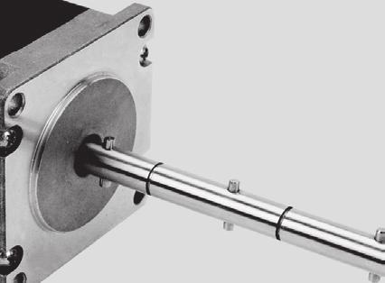
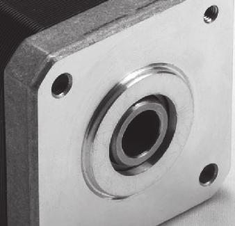
10 Motor Installation Mounting Direction Motors can be mounted freely in any direction as shown below Regardless of how the motor is mounted, take care not to apply an overhung load or thrust load on the shaft Make sure the cable does not contact the mounting surface causing undesirable force on the cable Introduction Quick Selection -phase Stepper Motors -phase Stepper Motors UStepper Motors onfigurations Mounting Method onsidering heat radiation and vibration isolation as much as possible, mount the motor tightly against a metal plane Mounting Method for Through Hole Type Mounting Method for Tapped Hole Type Flange Pilot Spot Facing or Throgh Hole Mounting Plate Installation onditions Through Holes Flange Pilot Spot Facing or Throgh Hole Tapped Holes Mounting Plate Install the motor in a location that meets the following conditions, or the product may be damaged Indoors (This product is designed and manufactured to be installed within another device) Ambient temperature: -~+ (non-freezing) Ambient humidity: 8% or less (non-condensing) Not exposed to explosive, flammable or corrosive gases Not exposed to direct sunlight Not exposed to dust Not exposed to water or oil A place where heat can escape easily Not exposed to continuous vibration or excessive impact Notes: When installing the motor in an enclosed space such as a control box, or somewhere close to a heat-radiating object, vent holes should be used to prevent the motor from overheating Do not install the motor in a location where a source of vibration will cause the motor to vibrate
11 QUIK SEETION OF MOTOR step angle ( ) 9 8 Base Thickness mm) mm 8 8 Size Series NEMA AMHA7A 8 AMHAA SR / AM7HAA 98 NEMA7 ST AM7HAA 8 AM7HAA NEMA7 AM7HA AM7HA AMH AMH 7 NEMA AMH SR AMH8 7 / AMH8 ST AMH AMH 7 NEMA AMH AMH AMH 7 AMH7 NEMA8 AM8HY 7 AM8HY AMHS8 NEMA AMHS7 AMHS8 NEMA AMHYB 7 8 AM7HD 98 NEMA7 AM7HD8 8 AM7HD 8 AM7HDB AMHS AMHS9 7 AMHS SR / AMHS ST AMHS 7 NEMA AMHS 9 AMHSA AMHS8A 77 AMHSAA 9 AMHSB AMHS8B 77 AMHSAB NEMA AMHS 8 AMHS AMHD 9 NEMA AMHD Recommended Driver Model AMHD AMHD 7 NEMA AMHS9 7 AMHS 8 NEMA AMHS AMHD8 7 SRA AMHD8 8 9 NEMA / AMHD8 STA AMHD8 AMHD8 98 AMHSA 9 NEMA AMHSA AMHSA The torque range (mn M); Speed range ~ RPS Introduction Quick Selection -phase Stepper Motors -phase Stepper Motors UStepper Motors Moment range (Nm); Speed range ~ RPS onfigurations
 Holding Torque Drive current Resistance Rotor Inertia Mass Dielectric mm Nm A/Phase Ω/Phase g cm Kg 7 7 9 Max ± Ø + - () AWG U =7 + -M Depth min HOUSING:JST")
12 NEMA8( mm) -phase D8-8HY Series Introduction Quick Selection -phase Stepper Motors -phase Stepper Motors UStepper Motors onfigurations Model Shaft Wiring eads AM8HY-N AM8HY-N AM8HY-N AM8HY-N A Ø + - Ø + - AM8HY Ø - ± ± AM8HY Ø + - ± ± Max () Holding Torque Drive current Resistance Rotor Inertia Mass Dielectric mm Nm A/Phase Ω/Phase g cm Kg Max ± Ø + - () AWG U =7 + -M Depth min HOUSING:JST ZHR- TERMINA:JST SZH-T-P 7Max 8± 7 (9) Ø + - -M Depth min JST SB-ZR(F)(SN) HOUSING:JST ZHR- TERMINA:JST SZH-T-P AWG U ± Max These dimensions are for the double shaft models For the single shaft models, ignore the ( Max ± These dimensions are for the double shaft models For the single shaft models, ignore the ( Torque urves (Recommended Driver: SR or ST) AM8HY Microstep steps/rev urrent A Peak 8 Torque(N m) AM8HY Microstep steps/rev urrent A Peak Torque(N m) Phases Steps / Revolution ±% Step Accuracy N ( bs)push N ( bs) Pull Radial 8 N ( bs) At End of Shaft IP Rating Operating Temp - to + Insulation lass B, Insulation Resistance MegOhms () 7 + ± Max ± Max ) area ) area VA minute
 ± Housing P/N : MOEX - rimp P/N : MOEX -8 AWG U PIN No + Ø- Torque urves(recommended Driver: SR or ST) Torque(N m) AMHS8 Microstep steps/rev urrent A Peak 8 AMHS7 Microstep steps/rev urrent A")
13 NEMA( 8mm) -phase D 8 - HS Series Model Shaft Wiring eads AMHS8-7 Holding Torque Drive current Resistance Rotor Inertia Mass Dielectric mm N m A/Phase Ω/Phase g cm Kg 9 AMHS7- A 8 7 AMHS8-8 + Ø- ± ± ± ± (9) ± Housing P/N : MOEX - rimp P/N : MOEX -8 AWG U PIN No + Ø- Torque urves(recommended Driver: SR or ST) Torque(N m) AMHS8 Microstep steps/rev urrent A Peak 8 AMHS7 Microstep steps/rev urrent A Peak 8 Torque(mN m) Phases Steps / Revolution ±% Step Accuracy N ( bs)push N ( bs) Pull Radial N ( bs) At Flat enter IP Rating Operating Temp - to + Insulation lass B, Insulation Resistance MegOhms 8Max ± () () - : ± 8Max MOEX -7 ± -M Depth Min VA minute AMHS8 Microstep steps/rev urrent A Peak 9 Torque(mN m) Introduction Quick Selection -phase Stepper Motors -phase Stepper Motors UStepper Motors onfigurations
 Torque(N m) AMHYB Microstep steps/rev urrent A")
14 NEMA( mm) -phase D 8 - HY Series Introduction Quick Selection -phase Stepper Motors -phase Stepper Motors UStepper Motors onfigurations Model Shaft Wiring eads Holding Torque Drive current Resistance Rotor Inertia Mass Dielectric mm Nm A/Phase Ω/Phase g cm Kg AMHYB- A VA minute + Ø- ± ± ± + Ø- - ± AWG U Torque urves (Recommended Driver: SR or ST) Torque(N m) AMHYB Microstep steps/rev urrent A Peak 9 Phases Steps / Revolution ±% Step Accuracy N ( bs)push N ( bs) Pull Radial N ( bs) At End of Shaft IP Rating Operating Temp - to + Insulation lass B, Insulation Resistance MegOhms Max ± ± -M Depth Min ± Max
 AMHA7A")
15 NEMA( mm) -phase D 9 - HA Series Model Shaft Wiring eads AMHA7A-N AMHA7A-N AMHAA-N AMHAA-N A Ø + - ± Ø + - ± -(:) Holding Torque Drive current Resistance Rotor Inertia Mass Dielectric mm N m A/Phase Ω/Phase g cm Kg ± ± ± M Depth Min AWG U Max ± These dimensions are for the double shaft models For the single shaft models, ignore the ( Torque urves (Recommended Driver: SR or ST) AMHA7A Microstep steps/rev urrent A Peak AMHAA Microstep steps/rev urrent A Peak 8 Phases Steps / Revolution ±% Step Accuracy N ( bs)push N ( bs) Pull Radial N ( bs) At Flat enter IP Rating Operating Temp - to + Insulation lass B, Insulation Resistance MegOhms ± ± Max ) area VA minute Introduction Quick Selection -phase Stepper Motors -phase Stepper Motors UStepper Motors onfigurations
16 NEMA7( mm) -phase D 8-7HD Series Introduction Quick Selection -phase Stepper Motors -phase Stepper Motors UStepper Motors onfigurations Model Shaft Wiring eads AM7HD-N AM7HD-N AM7HD8-N AM7HD8-N AM7HD-N AM7HD-N AM7HDB-N AM7HDB-N A + Ø- ± ± ± + Ø- -(:) ± Holding Torque Drive current Resistance Rotor Inertia Mass Dielectric mm N m A/Phase Ω/Phase g cm Kg ± AWG U Torque urves (Recommended Driver: SR or ST) Torque(N m) Torque(N m) AM7HD Microstep steps/rev urrent 8A Peak AM7HDB Microstep steps/rev urrent 8A Peak 7 Torque(N m) Phases Steps / Revolution ±% Step Accuracy N ( bs)push N ( bs) Pull Radial N ( bs) At Flat enter IP Rating Operating Temp - to + Insulation lass B, Insulation Resistance MegOhms Max ± ± -M Depth Min ± Max These dimensions are for the double shaft models For the single shaft models, ignore the ( ) area AM7HD8 Microstep steps/rev urrent 8A Peak Torque(N m) VA minute AM7HD Microstep steps/rev urrent 8A Peak
17 NEMA7( mm) -phase D 9-7HA Series Model Shaft Wiring eads AM7HAA-N AM7HAA-N AM7HAA-N AM7HAA-N AM7HAA-N AM7HAA-N A Ø + - Ø + - ± ± ± -(:) ± Holding Torque Drive current Resistance Rotor Inertia Mass Dielectric mm N m A/Phase Ω/Phase g cm Kg ± -M Depth Min AWG U Max ± These dimensions are for the double shaft models For the single shaft models, ignore the ( Torque urves (Recommended Driver: SR or ST) AM7HAA Microstep steps/rev urrent A Peak AM7HAA Microstep steps/rev urrent A Peak Phases Steps / Revolution ±% Step Accuracy N ( bs)push N ( bs) Pull Radial N ( bs) At Flat enter IP Rating Operating Temp - to + Insulation lass B, Insulation Resistance MegOhms ± ± Max ) area AM7HAA Microstep steps/rev urrent A Peak VA minute Introduction Quick Selection -phase Stepper Motors -phase Stepper Motors UStepper Motors onfigurations 7
18 NEMA( mm) -phase D 8 - HS Series Introduction Quick Selection -phase Stepper Motors -phase Stepper Motors UStepper Motors onfigurations 8 Model Shaft Wiring eads AMHS- AMHS- AMHS9- AMHS9- AMHS- AMHS- AMHS- AMHS- AMHS- AMHS- AMHS- AMHS- A Ø8± ± 8± Holding Torque Drive current Resistance Rotor Inertia Mass Dielectric mm N m A/Phase Ω/Phase g cm Kg ± ± ± + Ø- -(:) 8± ± AWG U Max 7± These dimensions are for the double shaft models For the single shaft models, ignore the ( Torque urves (Recommended Driver: SR or ST) AMHS Microstep steps/rev V 8V urrent A Peak AMHS Microstep steps/rev V 8V 7V urrent A Peak Phases Steps / Revolution ±% Step Accuracy N (9 bs)push N ( bs) Pull Radial 7 N ( bs) At Flat enter IP Rating Operating Temp - to + Insulation lass B, Insulation Resistance MegOhms AMHS9 Microstep steps/rev V 8V urrent A Peak 8 AMHS Microstep steps/rev V 8V 7V urrent A Peak 8 ± 8 Torque(N m) -Ø + - 7± Max ) area AMHS Microstep steps/rev urrent A Peak AMHS Microstep steps/rev V 8V 7V urrent A Peak 8 9 VA minute
19 NEMA( mm) -phase D 8 - HS PowerPlus Series (mm Shaft) Model Shaft Wiring eads AMHSA- AMHSA- AMHS8A- AMHS8A- AMHSAA- AMHSAA- AMHSB- AMHSB- AMHS8B- AMHS8B- AMHSAB- AMHSAB- A Ø8± ± ± ± 8± Ø- -(:) Holding Torque Drive current Resistance Rotor Inertia Mass Dielectric mm N m A/Phase Ω/Phase g cm Kg 8± ± ± AWG U 7± These dimensions are for the double shaft models For the single shaft models, ignore the ( Torque urves (Recommended Driver: SR or ST) Torque(N m) AMHSB Microstep steps/rev urrent A Peak Torque(N m) AMHSB Microstep steps/rev V 8V urrent A Peak V 8V AMHS8A Microstep steps/rev urrent A Peak 9 Torque(N m) Torque(N m) Phases Steps / Revolution ±% Step Accuracy N (9 bs)push N ( bs) Pull Radial 7 N ( bs) At Flat enter IP Rating Operating Temp - to + Insulation lass B, Insulation Resistance MegOhms AMHS8B Microstep steps/rev urrent A Peak 9 ± Torque(N m) -Ø + 7± Max ) area AMHSAA VA minute Microstep steps/rev V 8V urrent A Peak 8 8 Torque(N m) AMHSAB Microstep steps/rev urrent A Peak Introduction Quick Selection -phase Stepper Motors -phase Stepper Motors UStepper Motors onfigurations 9
20 NEMA( mm) -phase D 8 - HS PowerPlus Series (8mm Shaft) Introduction Quick Selection -phase Stepper Motors -phase Stepper Motors UStepper Motors onfigurations Model Shaft Wiring eads AMHSB- AMHSB- AMHS8B- AMHS8B- AMHSAB- AMHSAB- A Ø8± Ø8 + - ± ± ± 8± -(:) 7± Ø Holding Torque Drive current Resistance Rotor Inertia Mass Dielectric mm N m A/Phase Ω/Phase g cm Kg ± D-D(:) ± ± D 8± AWG U 7± ± ± These dimensions are for the double shaft models For the single shaft models, ignore the ( Torque urves (Recommended Driver: SR or ST) Torque(N m) AMHSB Microstep steps/rev urrent A Peak V 8V AMHS8B Microstep steps/rev urrent A Peak 9 Torque(N m) Phases Steps / Revolution ±% Step Accuracy N (9 bs)push N ( bs) Pull Radial 7 N ( bs) At Flat enter IP Rating Operating Temp - to + Insulation lass B, Insulation Resistance MegOhms 8 Torque(N m) AMHSAB Microstep steps/rev urrent A Peak -Ø + 7± Max ) area VA minute
21 NEMA( mm) -phase D 8 - HS Series Model Shaft Wiring eads AMHS-8N AMHS-N AMHS-N AMHS-N A Ø8± ± ± ± 7± + Ø8-7± -(:) 7± 9 Holding Torque Drive current Resistance Rotor Inertia Mass Dielectric mm N m A/Phase Ω/Phase g cm Kg Ø- ± ± D D D-D(:) AWG U 8± Max 7± These dimensions are for the double shaft models For the single shaft models, ignore the ( Torque urves (Recommended Driver: SR or ST) Phases Steps / Revolution ±% Step Accuracy N (9 bs)push N ( bs) Pull Radial 7 N ( bs)at Flat enter IP Rating Operating Temp - to + Insulation lass B, Insulation Resistance MegOhms ± -ر 7± Max ) area VA minute Introduction Quick Selection -phase Stepper Motors -phase Stepper Motors UStepper Motors AMHS Microstep steps/rev urrent A Peak V 8V 7V AMHS Microstep steps/rev urrent A Peak V 8V 7V 8 8 onfigurations
22 Introduction Quick Selection -phase Stepper Motors -phase Stepper Motors UStepper Motors onfigurations NEMA( 8mm) -phase D 8 - HD Series Model Shaft Wiring eads AMHD-8 AMHD-9 AMHD- AMHD-7 AMHD-7 AMHD-8 AMHD- AMHD- A Ø7± 7± ± ± - ± Holding Torque urrent Resistance Rotor Inertia Mass Dielectric mm N m A/Phase Ω/Phase g cm Kg AWG U ± () ± ± () D D D-D(:) 8Max 9± + Ø9- + Ø- ± These dimensions are for the double shaft models For the single shaft models, ignore the ( Torque urves (Recommended Driver: SR or ST) Torque(N m) Torque(N m) AMHD Microstep steps/rev V 8V 7V urrent 7A Peak AMHD Microstep: steps/rev urrent: 7A(Peak) 8 V 8V 7V ± Torque(N m) AMHD Microstep steps/rev urrent 7A Peak Phases Steps / Revolution ±% Step Accuracy N ( bs)push N ( bs) Pull Radial N ( bs) At Flat enter IP Rating Operating Temp - to + Insulation lass B, Insulation Resistance MegOhms 8± V 8V 7V () Torque(N m) -ر 9± 8Max ) area VA minute AMHD Microstep: steps/rev V 8V 7V urrent: 7A(Peak) 8 7
23 NEMA( mm) -phase A8 - HS Series Model Shaft Wiring eads Holding Torque Drive current Resistance Rotor Inertia Mass Dielectric mm Nm A/Phase Ω/Phase g cm Kg AMHS9- VA A AMHS- 7 8 minute Ø8± + Ø8- ± ± ± 8± -(:) 7± AWG U Torque urves (Recommended Driver: SRA or STA) AMHS9 Microstep steps/rev urrent A Peak 9 V Torque(mN m) AMHS Microstep steps/rev urrent A Peak 8 Phases Steps / Revolution ±% Step Accuracy N (9 bs)push N ( bs) Pull Radial 7 N ( bs) At Flat enter IP Rating Operating Temp - to + Insulation lass B, Insulation Resistance MegOhms V 7± -Ø + - ± 7± Max Introduction Quick Selection -phase Stepper Motors -phase Stepper Motors UStepper Motors onfigurations
24 NEMA( mm) -phase A8 - HS Series Introduction Quick Selection -phase Stepper Motors -phase Stepper Motors UStepper Motors onfigurations Model Shaft Wiring eads Holding Torque Drive current Resistance Rotor Inertia Mass Dielectric mm Nm A/Phase Ω/Phase g cm Kg AMHS-N A 8 9 Ø + -9 Ø + - ± ± ± 7± -(:) 9± AWG U ± ± Torque urves (Recommended Driver: SRA or STA) AMHS Microstep steps/rev urrent A Peak V Phases Steps / Revolution ±% Step Accuracy N (9 bs)push N ( bs) Pull Radial 7 N ( bs) At Flat enter IP Rating Operating Temp - to + Insulation lass B, Insulation Resistance MegOhms ± -ر ± ± VA minute
25 NEMA( 8mm) -phase A 8 - HD Series Model Shaft Wiring eads Holding Torque Drive current Resistance Rotor Inertia Mass Dielectric mm Nm A/Phase Ω/Phase g cm Kg AMHD8- AMHD8- AMHD8-7 8 (V Series 9 AMHD8- connection) B(Parallel) 8 9 / AMHD8- (Series) 8 7 AMHD8- (V Parallel connection) AMHD AMHD8- Wiring Diagram / B See Page 9 + Ø- + Ø9- - ± D-D(:) 8± 9 ± Ø7± 7± ± ± ± AWG U ± () ± ± These dimensions are for the double shaft models For the single shaft models, ignore the ( Torque urves (Recommended Driver: SRA or STA) Torque(N m) Torque(N m) AMHD8 Microstep steps/rev V / V urrent 8A / A Peak AMHD8 Microstep steps/rev V / V urrent 8A / A Peak Torque(N m) Torque(N m) Phases Steps / Revolution ±% Step Accuracy N ( bs)push N ( bs) Pull Radial N ( bs) At Flat enter IP Rating Operating Temp - to + Insulation lass B, Insulation Resistance MegOhms () AMHD8 Microstep steps/rev V / V urrent 8A / A Peak AMHD8 Microstep steps/rev V / V urrent 8A / A Peak 7 D D Torque(N m) 8Max 9± () ) area VA minute -ر 9± 8Max AMHD8 Microstep steps/rev V / V urrent 8A / A Peak Introduction Quick Selection -phase Stepper Motors -phase Stepper Motors UStepper Motors onfigurations
 () Torque urves (Recommended Driver: SRA or STA) AMHSA")
26 NEMA( mm) -phase A 8 - HS Series Introduction Quick Selection -phase Stepper Motors -phase Stepper Motors UStepper Motors onfigurations Model Shaft Wiring eads AMHSA- Holding Torque urrent Resistance Rotor Inertia Mass Dielectric mm Nm A/Phase Ω/Phase g cm Kg 98 8 AMHSA- A AMHSA- 7 Ø - - : M Min ر ± + ± ± Ground AWG8 U ± () () Torque urves (Recommended Driver: SRA or STA) AMHSA Microstep: steps/rev urrent: A(Peak) 8 V AMHSA Microstep: steps/rev urrent: A(Peak) 8 Phases Steps / Revolution ±% Step Accuracy N ( bs)push N ( bs) Pull Radial N ( bs) At Flat enter IP Rating Operating Temp - to + Insulation lass B, Insulation Resistance MegOhms V Max 89± () AMHSA Microstep: steps/rev urrent: 7A(Peak) V 89± Max VA minute -Ø8 +
27 NEMA( mm) -phase D8 - HS Series IP Type Model Shaft Wiring eads Holding Torque Drive current Resistance Rotor Inertia Mass Dielectric mm Nm A/Phase Ω/Phase g cm Kg AMHS- 7 VA A AMHS minute Ø8± ± ± ± 7± + Ø- -(:) 8± ± Oil AWG U7 Torque urves (Recommended Driver: SR or ST) AMHS Microstep steps/rev urrent A Peak 8 V 8V 7V Phases Steps / Revolution ±% Step Accuracy N (9 bs)push N ( bs) Pull Radial 7 N ( bs) At Flat enter IP Rating Operating Temp - to + Insulation lass B, Insulation Resistance MegOhms AMHS Microstep steps/rev V 8V 7V urrent A Peak 8 9 7± -Ø + - 7± Max Introduction Quick Selection -phase Stepper Motors -phase Stepper Motors UStepper Motors onfigurations 7
28 NEMA( mm) -phase D8 - HS Series IP Type Introduction Quick Selection -phase Stepper Motors -phase Stepper Motors UStepper Motors onfigurations Model Shaft Wiring eads Holding Torque Drive current Resistance Rotor Inertia Mass Dielectric mm Nm A/Phase Ω/Phase g cm Kg AMHS-N A 9 9 Ø8± ± ± ± 8± + Ø8- -(:) 7± Oil AWG U7 Torque urves (Recommended Driver: SR or ST) urrent A Peak 8 AMHS Microstep steps/rev V 8V 7V Phases Steps / Revolution ±% Step Accuracy N (9 bs)push N ( bs) Pull Radial 7 N ( bs) At Flat enter IP Rating Operating Temp - to + Insulation lass B, Insulation Resistance MegOhms ± 7± ± -ر 7± ± VA minute 8
29 NEMA( 8mm) -phase D8 - HD Series IP Type Model Shaft Wiring eads Holding Torque Drive current Resistance Rotor Inertia Mass Dielectric mm Nm A/Phase Ω/Phase g cm Kg AMHD VA A 7 AMHD minute ± Ø7± ± + Ø- 7± ± ± - 9 ± ± AWG U7 Torque urves (Recommended Driver: SR or ST) Torque(N m) AMHD Microstep steps/rev urrent 7A Peak AMHD V 8V 7V Microstep: steps/rev urrent: 7A(Peak) Torque(N m) Phases Steps / Revolution ±% Step Accuracy N ( bs)push N ( bs) Pull Radial N ( bs) At Flat enter IP Rating Operating Temp - to + Insulation lass B, Insulation Resistance MegOhms ± oil V 8V 7V 8 7 8± 9± -ر 9± 8± Introduction Quick Selection -phase Stepper Motors -phase Stepper Motors UStepper Motors onfigurations 9
 Black(V-) Drive current Resistance () Rotor Inertia -M Depth Min Brake Torque AWG U Brake Power mm Nm A/Phase Ω/Phase g cm Nm")
 AM7HD8 Microstep steps/rev urrent 8A Peak Torque(N m) ± ± Max Dielectric VA minute AM7HD Microstep steps/rev")
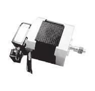
30 NEMA7( mm) -phase D8-7HD Series Brake type ± ± Brake Max ± Introduction Quick Selection -phase Stepper Motors -phase Stepper Motors UStepper Motors onfigurations Ø - Ø - ± - Model Shaft Wiring eads ength Holding Torque AM7HD-BR : ± AWG U Red(V+) Black(V-) Drive current Resistance () Rotor Inertia -M Depth Min Brake Torque AWG U Brake Power mm Nm A/Phase Ω/Phase g cm Nm V(W) Kg AM7HD8-BR Single () A AM7HD-BR Shaft () Mass 8 8 () 8 AM7HDB-BR () 7 Torque urves (Recommended Driver: SR or ST) Torque(N m) Torque(N m) AM7HD Microstep steps/rev urrent 8A Peak AM7HDB Microstep steps/rev urrent 8A Peak 7 Torque(N m) AM7HD8 Microstep steps/rev urrent 8A Peak Torque(N m) ± ± Max Dielectric VA minute AM7HD Microstep steps/rev urrent 8A Peak
 Black(V-) Rotor Inertia Brake Torque AWG U Brake Power mm Nm A/Phase Ω/Phase g cm Nm V(W) Kg AMHSB-BR 8 8 8 () AMHS8B-BR Single Shaft A 9 () 8 AMHSAB-BR 8 7 ()")

31 NEMA( mm) -phase D8 - HS Series Brake type ± Brake 7± -Ø + - Ø8± Ø8 - Model Shaft Wiring eads Holding Torque ± ID ID ± 8± D-D : Drive current 7± Resistance = AWG U Red(V+) Black(V-) Rotor Inertia Brake Torque AWG U Brake Power mm Nm A/Phase Ω/Phase g cm Nm V(W) Kg AMHSB-BR () AMHS8B-BR Single Shaft A 9 () 8 AMHSAB-BR 8 7 () Torque urves (Recommended Driver: SR or ST) Torque(N m) AMHSB Microstep steps/rev urrent A Peak V 8V AMHS8B Microstep steps/rev urrent A Peak 9 Torque(N m) 8 Torque(N m) AMHSAB Microstep steps/rev urrent A Peak ± Mass 7± Max Dielectric VA minute Introduction Quick Selection -phase Stepper Motors -phase Stepper Motors UStepper Motors onfigurations
32 NEMA( mm) -phase D8 - HS Series Brake type ± Brake ± 7± -ر Introduction Quick Selection -phase Stepper Motors -phase Stepper Motors UStepper Motors onfigurations Ø8 - ± I I ± 7± Ø8-7± - : 9 ' 7± Holding Torque Drive urrent = AWG U Red(V+) Black(V-) Rotor Inertia AWG U Brake Torque ± Brake Power Resistance Mass Model Shaft Wiring eads mm Nm A/Phase Ω/Phase g cm Nm V(W) Kg AMHS-BR Single 9 A () AMHS-BR Shaft 9 Torque urves (Recommended Driver: SR or ST) AMHS Microstep steps/rev V 8V 7V urrent A Peak 8 AMHS Microstep steps/rev V 8V 7V urrent A Peak 8 7± ± Dielectric VA minute
/Black(V-) Rotor Inertia AWG U Brake Torque Brake Power")

33 NEMA( mm) -phase A8 - HS Series Brake type ± ± ± -Ø + Brake Ø - Ø - ± ± - : 7± Model Shaft Wiring eads Holding Torque AMHS-BR Single Shaft 9± Drive current Resistance Ground = AWG U7 Yellow/Green AWG U Red(V+)/Black(V-) Rotor Inertia AWG U Brake Torque Brake Power 9± mm Nm A/Phase Ω/Phase g cm Nm V(W) Kg A 9 () Torque urves (Recommended Driver: SRA or STA) AMHS Microstep steps/rev urrent A Peak V ± Mass ± ± Dielectric VA minute Introduction Quick Selection -phase Stepper Motors -phase Stepper Motors UStepper Motors onfigurations
/Black(V-) () Rotor Drive urrent Resistance Holding Torque Inertia Brake Torque Brake Power mm Nm A/Phase Ω/Phase g cm Nm V(W) Kg 8 AMHD-BR A 8 7 8")
34 NEMA( 8mm) -phase D8 / -phase A8 -HD Series Brake type 7± 8± 9± -ر ± Introduction Quick Selection -phase Stepper Motors -phase Stepper Motors UStepper Motors onfigurations Ø7± Model Shaft Wiring eads AMHD-BR ± ± Ø - AWG U - ± 9 ± ± ± Red(V+)/Black(V-) () Rotor Drive urrent Resistance Holding Torque Inertia Brake Torque Brake Power mm Nm A/Phase Ω/Phase g cm Nm V(W) Kg 8 AMHD-BR A AMHD-BR () AMHD8-BR 8 AMHD8-BR 8 8 8(VA) 8 AMHD8-BR Torque urves (Recommended Driver: SR or ST) Torque(N m) AMHD Microstep steps/rev V 8V 7V urrent 7A Peak Torque(N m) AMHD Microstep steps/rev urrent 7A Peak V 8V 7V Torque urves (Recommended Driver: SRA or STA) Torque(N m) AMHD8 Microstep steps/rev V / V urrent 8A / A Peak Torque(N m) AMHD8 Microstep steps/rev V / V urrent 8A / A Peak Torque(N m) Torque(N m) () Mass AMHD Microstep: steps/rev V 8V 7V urrent: 7A(Peak) 8 7 AMHD8 Microstep steps/rev V / V urrent 8A / A Peak 7 9± 8± Dielectric VA minute VA minute
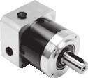
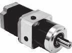
35 NEMA7( mm) -phase D8-7HD Series Planetary Reducer Motor Type Ø -8 ± Ø Ø - Ø AWG U ± -M Depth M Depth Model Wiring Drive Maximum Maximum Rotor current Reduction Accuracy Noise Mass Series output torque load torque Inertia Efficiency ratio mm A/Phase arc-min Nm Nm gcm db Kg AM7HD-PG 8 9 9% AM7HD-PG 8 8 9% AM7HD-PG 8 9% A 8 < AM7HD8-PG 7 9% AM7HD8-PG 7 7 9% AM7HD8-PG 8 8 9% 8 Torque urves 8 8 AM7HD-PG Microstep steps/rev urrent 8A(Peak) V 8V 8 AM7HD8-PG Microstep: steps/rev V 8V urrent: 8A(Peak) 8 (Recommended Driver: SR or ST) AM7HD-PG Microstep steps/rev urrent 8A(Peak) V 8V AM7HD8-PG Microstep: steps/rev urrent: 8A(Peak) V 8V 8 AM7HD-PG Microstep: steps/rev urrent: 8A(Peak) V 8V AM7HD8-PG Microstep: steps/rev urrent: 8A(Peak) V 8V Ø Introduction Quick Selection -phase Stepper Motors -phase Stepper Motors UStepper Motors onfigurations
36 NEMA7( mm) -phase D8-7HD Series Planetary Reducer Motor Type Introduction Quick Selection -phase Stepper Motors -phase Stepper Motors UStepper Motors onfigurations Model AM7HD-PG Wiring Ø -8 ± Ø Ø - Ø AWG U ± -M Depth M Depth Drive current Series Reduction Maximum Maximum Rotor Accuracy Noise Mass output torque load torque Inertia Efficiency ratio mm A/Phase arc-min Nm Nm gcm db Kg 8 9% AM7HD-PG % 8 AM7HD-PG % 7 A < AM7HDB-PG 7 9% 9 AM7HDB-PG 8 9% 9 AM7HDB-PG 7 9 9% Torque urves AM7HD-PG Microstep steps/rev urrent 8A(Peak) V 8V 8 AM7HDB-PG Microstep steps/rev urrent 8A(Peak) V 8V 8 (Recommended Driver: SR or ST) AM7HD-PG Microstep: steps/rev urrent: 8A(Peak) V 8V AM7HDB-PG Microstep steps/rev urrent 8A(Peak) V 8V 8 8 AM7HD-PG Microstep: steps/rev urrent: 8A(Peak) V 8V AM7HDB-PG Microstep steps/rev urrent 8A(Peak) V 8V Ø 8

 V V 8V 8V (Recommended Driver: SR or ST) 7 8 8 AMHSB-PG Microstep steps/rev urrent A(Peak) V 8V AMHS8B-PG Microstep steps/rev urrent A(Peak) V 8V AMHSAB-PG Microstep: steps/rev urrent:")
37 NEMA( mm) -phase D8 - HS Series Planetary Reducer Motor Type ± ± Ø -8 Ø Model AMHSB-PG Wiring Ø7 Ø - Ø M Depth Ø AWG U ± ± -M DEPTH 8 Drive current Series Reduction Maximum Maximum Rotor Accuracy Noise Mass output torque load torque Inertia Efficiency ratio mm A/Phase arc-min Nm Nm gcm db Kg 9% < AMHSB-PG 8 9% < AMHSB-PG 9% < AMHS8B-PG % < AMHS8B-PG A 8 9% < AMHS8B-PG 8 9% < AMHSAB-PG 9 9% < 8 AMHSAB-PG 9% < 8 AMHSAB-PG 9% < 7 Torque urves 8 AMHSB-PG Microstep steps/rev urrent A(Peak) V 8V 8 AMHS8B-PG Microstep steps/rev urrent A(Peak) 8 AMHSAB-PG Microstep: steps/rev urrent: A(Peak) V V 8V 8V (Recommended Driver: SR or ST) AMHSB-PG Microstep steps/rev urrent A(Peak) V 8V AMHS8B-PG Microstep steps/rev urrent A(Peak) V 8V AMHSAB-PG Microstep: steps/rev urrent: A(Peak) V 8V 8 AMHSB-PG Microstep steps/rev urrent A(Peak) V 8V AMHS8B-PG Microstep steps/rev urrent A(Peak) V 8V AMHSAB-PG Microstep: steps/rev V 8V urrent: A(Peak) Introduction Quick Selection -phase Stepper Motors -phase Stepper Motors UStepper Motors 8 onfigurations 7

38 NEMA( mm) -phase D8 - HS Series Planetary Reducer Motor Type ± ± Ø -8 Ø Introduction Quick Selection -phase Stepper Motors -phase Stepper Motors UStepper Motors onfigurations Model AMHS-PG Wiring Ø7 Ø - Ø M Depth Ø AWG U ± ± -M DEPTH 8 Drive current Series Reduction Maximum Maximum Rotor Accuracy Noise Mass output torque load torque Inertia Efficiency ratio mm A/Phase arc-min Nm Nm gcm db Kg 7 9% < AMHS-PG 7 9% < AMHS-PG 8 9% < 87 A AMHS-PG 8 9% < AMHS-PG 8 9 9% < AMHS-PG 7 9% < Torque urves 8 AMHS-PG Microstep steps/rev urrent A(Peak) V 8V 8 AMHS-PG Microstep steps/rev urrent A(Peak) V 8V 8 (Recommended Driver: SR or ST) 8 AMHS-PG Microstep steps/rev urrent A(Peak) V 8V AMHS-PG Microstep steps/rev urrent A(Peak) V 8V AMHS-PG Microstep steps/rev urrent A(Peak) V 8V AMHS-PG Microstep steps/rev urrent A(Peak) V 8V 8
39 NEMA( 8mm) -phase D8 - HD Series Planetary Reducer Motor Type Model AMHD-PG Wiring Ø - ± 8 Ø Ø - Ø8 () -M Depth Ø7 8± AWG8 U ± () () 8± M Depth 8 Drive current Series Reduction Maximum Maximum Rotor Accuracy Noise Mass output torque load torque Inertia Efficiency ratio mm A/Phase arc-min Nm Nm gcm db Kg 7 7 9% AMHD-PG 7 9% 7 AMHD-PG 88 9% AMHD-PG 9% 8 AMHD-PG A 7 8 9% < 8 AMHD-PG 8 7 9% AMHD-PG % 9 AMHD-PG % 9 AMHD-PG 7 9% Torque urves 8 AMHD-PG Microstep steps/rev urrent 7A(Peak) 8 AMHD-PG Microstep steps/rev urrent 7A(Peak) (Recommended Driver: SR or ST) V 8V 7V 8 AMHD-PG Microstep: steps/rev urrent: 7A(Peak) V 8V 7V V 8V 7V 8 AMHD-PG Microstep steps/rev urrent 7A(Peak) V 8V 7V AMHD-PG Microstep: steps/rev V 8V 7V urrent: 7A(Peak) AMHD-PG Microstep: steps/rev urrent: 7A(Peak) V 8V 7V 8 AMHD-PG Microstep steps/rev urrent 7A(Peak) V 8V 7V AMHD-PG Microstep: steps/rev V 8V 7V urrent: 7A(Peak) AMHD-PG Microstep: steps/rev urrent: 7A(Peak) V 8V 7V 7 Introduction Quick Selection -phase Stepper Motors -phase Stepper Motors UStepper Motors 8 8 onfigurations 9
40 NEMA( 8mm) -phase A8 - HD Series Planetary Reducer Motor Type Introduction Quick Selection -phase Stepper Motors -phase Stepper Motors UStepper Motors onfigurations Model AMHD8-PG Wiring Ø - ± 8 Ø Ø - Ø8 () -M Depth Ø7 8± AWG8 U ± () () 8± M Depth 8 Drive current Series Reduction Maximum Maximum Rotor Accuracy Noise Mass output torque load torque Inertia Efficiency ratio mm A/Phase arc-min Nm Nm gcm db Kg 7 7 9% AMHD8-PG 7 9% 7 AMHD8-PG 88 9% AMHD8-PG 9% 8 AMHD8-PG 8 8 9% < 8 AMHD8-PG 8 7 9% AMHD8-PG % 9 AMHD8-PG % 9 AMHD8-PG 7 9% Wiring Diagram See Page 9 Torque urves 8 AMHD8-PG Microstep steps/rev urrent 8A(Peak) 8 AMHD8-PG Microstep steps/rev urrent 8A(Peak) (Recommended Driver: SRA or STA) V 8 AMHD8-PG Microstep steps/rev urrent 8A(Peak) V V 8 7 AMHD8-PG Microstep steps/rev urrent 8A(Peak) V AMHD8-PG Microstep: steps/rev urrent: 8A(Peak) V AMHD8-PG Microstep steps/rev urrent 8A(Peak) V 8 8 AMHD8-PG Microstep steps/rev urrent 8A(Peak V AMHD8-PG Microstep: steps/rev urrent: 8A(Peak) V AMHD8-PG Microstep steps/rev urrent 8A(Peak) V 7

 General encoder able P/N: - ength: m P/N: 9- ength: m Encoder cable used with MOONS drive P/N: - ength: m P/N: - ength: m Holding Torque Drive current Model Wiring eads")
41 NEMA7( mm) -phase D 8-7HD Series Encoder Type ± 9± Max ± () + Ø - -(:) Encode Electrical Specification Resolution Supply urrent (no load) Output Voltage ow Output Voltage High ± ounts/rev( ine) Typ ma/max 9mA V@mA Max V@-mA Min A leads B for clockwise shaft rotation, and B leads A for counterclockwise rotation viewed from direction H Mating onnectors Housing: Molex# -- rimp: Molex# --8 rimp Tool: Molex# -7 omponent model: E-onnector (8) A Ø + - ± PIN 9 ± View A PIN PIN PIN H Encoder -M Depth Min AWG U ± ± Max Pin Signal N Ground Index- Index+ A- Pin Signal A+ +V D N B- B+ Accessories(Sold Separately) General encoder able P/N: - ength: m P/N: 9- ength: m Encoder cable used with MOONS drive P/N: - ength: m P/N: - ength: m Holding Torque Drive current Model Wiring eads Resistance Rotor Inertia Motor Mass mm N m A/Phase Ω/Phase g cm Kg AM7HD-ED 8 8 AM7HD8-ED A AM7HD-ED AM7HDB-ED 8 8 Torque urves (Recommended Driver: SR or ST) Torque(N m) AM7HD Microstep steps/rev urrent 8A Peak Torque(N m) AM7HD8 Torque(N m) AM7HD Microstep steps/rev urrent 8A Peak Introduction Quick Selection -phase Stepper Motors -phase Stepper Motors UStepper Motors Torque(N m) AM7HDB Microstep steps/rev urrent 8A Peak 7 onfigurations
 Output Voltage ow Output Voltage High 8± ounts/rev( ine) Typ ma/max 9mA V@mA Max V@-mA Min A leads B for clockwise shaft rotation, and B leads A for")
42 NEMA( mm) -phase D 8 - HS Series Encoder Type ± 9± 7± -Ø + - Introduction Quick Selection -phase Stepper Motors -phase Stepper Motors UStepper Motors onfigurations () Ø - -(:) Encode Electrical Specification Resolution Supply urrent (no load) Output Voltage ow Output Voltage High 8± ounts/rev( ine) Typ ma/max 9mA V@mA Max V@-mA Min A leads B for clockwise shaft rotation, and B leads A for counterclockwise rotation viewed from direction H Mating onnectors Housing: Molex# -- rimp: Molex# --8 rimp Tool: Molex# -7 omponent model: E-onnector arameters A (8) Ø8± ± ± 8± PIN 9 View A PIN PIN PIN H Encoder AWG U ± 7± Max Pin Signal N Ground Index- Index+ A- Pin Signal A+ +V D N B- B+ Accessories(Sold Separately) General encoder able P/N: - ength: m P/N: 9- ength: m Encoder cable used with MOONS drive P/N: - ength: m P/N: - ength: m Holding Torque Drive current Resistance Rotor Inertia Motor Mass Model Wiring eads mm N m A/Phase Ω/Phase g cm Kg AMHS-ED 8 AMHS9-ED AMHS-ED A AMHS-ED 8 AMHS-ED AMHS-ED Torque urves (Recommended Driver: SR or ST) AMHS Microstep steps/rev V 8V urrent A Peak AMHS Microstep steps/rev V 8V 7V urrent A Peak AMHS9 Microstep steps/rev V 8V urrent A Peak 8 AMHS Microstep steps/rev V 8V 7V urrent A Peak 8 8 Torque(N m) AMHS Microstep steps/rev urrent A Peak AMHS Microstep steps/rev V 8V 7V urrent A Peak 8 9
 Typ ma/max 9mA V@mA Max V@-mA Min A leads B for clockwise shaft rotation, and B leads A for counterclockwise rotation viewed from direction H Mating onnectors Housing: Molex# -- rimp: Molex# --8")
43 NEMA( mm) -phase D 8 - HD Series Encoder Type ± 9± Max 7± -ر () + Ø8-7± -(:) Encode Electrical Specification Resolution Supply urrent (no load) Output Voltage ow Output Voltage High 9 7± ounts/rev( ine) Typ ma/max 9mA V@mA Max V@-mA Min A leads B for clockwise shaft rotation, and B leads A for counterclockwise rotation viewed from direction H Mating onnectors Housing: Molex# -- rimp: Molex# --8 rimp Tool: Molex# -7 omponent model: E-onnector A (8) Ø8± ± ± PIN 9 View A PIN PIN PIN H Encoder AWG U Pin Signal N Ground Index- Index+ A- Pin Signal A+ +V D N B- B+ Accessories(Sold Separately) General encoder able P/N: - ength: m P/N: 9- ength: m Encoder cable used with MOONS drive P/N: - ength: m P/N: - ength: m Holding Torque Drive current Model Wiring eads Resistance Rotor Inertia Motor Mass mm N m A/Phase Ω/Phase g cm Kg AMHS-ED 8 A AMHS-ED 8 9 Torque urves (Recommended Driver: ST or SR) AMHS Microstep: steps/rev V 8V 7V urrent: A(Peak) 8 AMHS Microstep steps/rev V 8V 7V urrent A Peak 8 ± 7± Max Introduction Quick Selection -phase Stepper Motors -phase Stepper Motors UStepper Motors onfigurations
 Supply urrent (no load) Typ ma/max 9mA Output Voltage ow V@mA Max Output Voltage High V@-mA Min A leads B for clockwise shaft rotation, and B leads")
44 NEMA( 8mm) -phase D8 - HD Series Encoder Type 8REF 7± ± 9± 8± 9± -ر Introduction Quick Selection -phase Stepper Motors -phase Stepper Motors UStepper Motors onfigurations () ± Ø + - -(:) Encode Electrical Specification Resolution ounts/rev( ine) Supply urrent (no load) Typ ma/max 9mA Output Voltage ow V@mA Max Output Voltage High V@-mA Min A leads B for clockwise shaft rotation, and B leads A for counterclockwise rotation viewed from direction H Mating onnectors Housing: Molex# -- rimp: Molex# --8 rimp Tool: Molex# -7 omponent model: E-onnector A (8) 9 ± ± 8REF Ø7± ± AWG U ± ± PIN 9 ± View A PIN PIN PIN () () Encoder H () 9± 8± Pin Signal N Ground Index- Index+ A- Pin Signal A+ +V D N B- B+ Accessories(Sold Separately) General encoder able P/N: - ength: m P/N: 9- ength: m Encoder cable used with MOONS drive P/N: - ength: m P/N: - ength: m Model Wiring eads Drive Rotor Holding Torque current Resistance Inertia (Ω/Phase) Motor Mass mm N m A/Phase g cm Kg AMHD-ED AMHD-ED A AMHD-ED Torque urves (Recommended Driver: ST or SR) Torque(N m) AMHD Microstep steps/rev V 8V 7V urrent 7A Peak Torque(N m) AMHD Microstep steps/rev urrent 7A Peak V 8V 7V Torque(N m) Dielectric VA minute AMHD Microstep: steps/rev V 8V 7V urrent: 7A(Peak) 8 7

 General encoder able P/N: - ength: m P/N: 9- ength: m Encoder cable used with MOONS drive P/N: - ength: m P/N: - ength: m Drive current (A/Phase)")
45 NEMA( 8mm) -phase A8 - HD Series Encoder Type 8REF 7± ± 9± 8± 9± -ر () ± Ø + - -(:) Encode Electrical Specification Resolution ounts/rev( ine) Supply urrent (no load) Typ ma/max 9mA Output Voltage ow V@mA Max Output Voltage High V@-mA Min A leads B for clockwise shaft rotation, and B leads A for counterclockwise rotation viewed from direction H Mating onnectors Housing: Molex# -- rimp: Molex# --8 rimp Tool: Molex# -7 omponent model: E-onnector A (8) 9 ± ± Holding Torque 8REF Ø7± ± AWG U ± ± PIN 9 ± View A PIN PIN PIN () () Encoder H () Pin Signal N Ground Index- Index+ A- Pin Signal A+ +V D N B- B+ Accessories(Sold Separately) General encoder able P/N: - ength: m P/N: 9- ength: m Encoder cable used with MOONS drive P/N: - ength: m P/N: - ength: m Drive current (A/Phase) Resistance (Ω/Phase) Rotor Inertia Motor Mass Model Wiring eads mm N m Series Parallel Series Parallel g cm Kg AMHD8-ED 9 8(When (When B(Parallel) AMHD8-ED 8 9 drive by drive by (Series) VA) VA) AMHD8-ED Wiring Diagram AB See Page 9 Torque urves (Recommended Driver: SRA or STA) Torque(N m) AMHD8 Microstep steps/rev V / V urrent 8A / A Peak Torque(N m) AMHD8 Microstep steps/rev V / V urrent 8A / A Peak Torque(N m) 9± 8± Dielectric VA minute AMHD8 Microstep steps/rev V / V urrent 8A / A Peak 7 Introduction Quick Selection -phase Stepper Motors -phase Stepper Motors UStepper Motors onfigurations
 ± Holding Torque Drive urrent Resistance Rotor Inertia Mass Dielectric mm N m A/Phase Ω/Phase g cm Kg ± (7) 9 7 8 () () (Ø) () () 8± ± These")
46 NEMA7( mm) -phase D - 7H Series Introduction Quick Selection -phase Stepper Motors -phase Stepper Motors UStepper Motors onfigurations Model Shaft Wiring eads AM7HA-N AM7HA-N AM7HA-N AM7HA-N Wiring Diagram D See Page 9 D Ø - ± ± ± Ø + - ØMax -(:) ± Holding Torque Drive urrent Resistance Rotor Inertia Mass Dielectric mm N m A/Phase Ω/Phase g cm Kg ± (7) () () (Ø) () () 8± ± These dimensions are for the double shaft models For the single shaft models, ignore the ( Housing P/N:JST PHR- rimp P/N:JST SPH-T-PS Torque urves (Recommended Driver: ST or SR) AM7HA Microstep steps/rev urrent A Peak AM7HA Microstep: steps/rev urrent: A(Peak) Phases Steps / Revolution ±% Step Accuracy N ( bs) Push N ( bs) Pull Radial 9 N ( bs) At Flat enter IP Rating Operating Temp - to + Insulation lass B, Insulation Resistance MegOhms PIN NO ± -M DEPTH Min () AWG U ) area VA minute
47 NEMA( mm) -phase D - H Series 7 Flange Demension Model Shaft Wiring eads AMH- Holding Torque Drive urrent Resistance Rotor Inertia Mass Dielectric mm N m A/Phase Ω/Phase g cm Kg 8 AMH- D AMH- 7 Wiring Diagram D See Page 9 Ø8± ± ± ± ± + Ø8- -(:) 7± AWG U Torque urves (Recommended Driver: ST or SR) Torque (N m) AMH Microstep steps/rev urrent 7A Peak V 8V 7V Torque (N m) AMH Microstep steps/rev urrent 7A Peak Phases Steps / Revolution ±% Step Accuracy N (9 bs) Push N ( bs) Pull Radial 7 N ( bs) At Flat enter IP Rating Operating Temp - to + Insulation lass B, Insulation Resistance MegOhms V 8V 7V Max 7 ± Torque (N m) ± -Ø ± Max AMH Microstep steps/rev V 8V 7V urrent 7A Peak VA minute Introduction Quick Selection -phase Stepper Motors -phase Stepper Motors UStepper Motors onfigurations 7

 At Flat enter IP Rating Operating Temp - to + Insulation lass B, Insulation Resistance MegOhms Max 98± ± -Ø + - 98± Max AMH V 8V 7V 9 Torque(N m) VA")
48 NEMA( mm) -phase D - H Series Flange Demension Introduction Quick Selection -phase Stepper Motors -phase Stepper Motors UStepper Motors onfigurations Model Shaft Wiring eads AMH- Holding Torque Drive urrent Resistance Rotor Inertia Mass Dielectric mm N m A/Phase Ω/Phase g cm Kg 8 AMH8- D AMH-7 7 Wiring Diagram D See Page 9 + Ø- + Ø8- ± ± ± ± -(:) ± AWG U Torque urves (Recommended Driver: ST or SR) AMH V 8V 7V Torque(N m) AMH8 V 8V 7V 8 Torque(N m) Phases Steps / Revolution ±% Step Accuracy N (9 bs) Push N ( bs) Pull Radial 7 N ( bs) At Flat enter IP Rating Operating Temp - to + Insulation lass B, Insulation Resistance MegOhms Max 98± ± -Ø ± Max AMH V 8V 7V 9 Torque(N m) VA minute 8
 AWG8 U ± () -(:) 9 ± ± Torque urves (Recommended Driver: ST or SR) Torque (N m) AMH Microstep steps/rev urrent 7A Peak V 8V 7V Torque (N m) AMH Microstep")
49 NEMA( 8mm) -phase D - H Series Model Shaft Wiring eads AMH- Holding Torque Drive urrent Resistance Rotor Inertia Mass Dielectric mm N m A/Phase Ω/Phase g cm Kg AMH- D AMH Wiring Diagram D See Page 9 ± Ø7± ± + Ø- 7± ± ± () AWG8 U ± () -(:) 9 ± ± Torque urves (Recommended Driver: ST or SR) Torque (N m) AMH Microstep steps/rev urrent 7A Peak V 8V 7V Torque (N m) AMH Microstep steps/rev urrent 7A Peak Phases Steps / Revolution ±% Step Accuracy N ( bs) Push N ( bs) Pull Radial N ( bs) At Flat enter IP Rating Operating Temp - to + Insulation lass B, Insulation Resistance MegOhms V 8V 7V Torque (N m) 8± 9± () -ر 9± 8± AMH Microstep steps/rev V 8V 7V urrent 7A Peak VA minute Introduction Quick Selection -phase Stepper Motors -phase Stepper Motors UStepper Motors onfigurations 9
 AWG8 U ± () -(:) 9 ± ± Torque urves (Recommended")
50 NEMA( 8mm) -phase A - H Series Introduction Quick Selection -phase Stepper Motors -phase Stepper Motors UStepper Motors onfigurations Model Shaft Wiring eads AMH- Holding Torque Drive urrent Resistance Rotor Inertia Mass Dielectric mm N m A/Phase Ω/Phase g cm Kg 8 8 AMH- D AMH7-7 8 Wiring Diagram D See Page 9 ± Ø7± ± + Ø- 7± ± ± () AWG8 U ± () -(:) 9 ± ± Torque urves (Recommended Driver: SRA) N m) Torque ( AMH V N m) Torque ( AMH Phases Steps / Revolution ±% Step Accuracy N ( bs) Push N ( bs) Pull Radial N ( bs) At Flat enter IP Rating Operating Temp - to + Insulation lass B, Insulation Resistance MegOhms V N m) Torque ( 8± 9± () -ر 9± 8± AMH7 V VA minute
 8± 8 7 8 7 ± AWG U Max 7± These dimensions are for the double shaft models For the single shaft")
51 NEMA( mm) -phase D 8 - HS U Series Model Shaft Wiring eads MSHS8A- MSHS8A- MSHS88A- MSHS88A- MSHSA8A- MSHSA8A- MSHSl7A- MSHS7A- MSHS87A- MSHS87A- MSHSA7A- MSHSA7A- A Ø8± ± 8± Holding Torque Drive current Resistance Rotor Inertia Mass Dielectric mm N m A/Phase Ω/Phase g cm Kg ± ± ± + Ø- -(:) 8± ± AWG U Max 7± These dimensions are for the double shaft models For the single shaft models, ignore the ( Torque urves (Recommended Driver: SR or ST) AMHS Microstep steps/rev V 8V urrent A Peak MSHSl7A Microstep steps/rev V 8V 7V urrent A Peak Phases Steps / Revolution ±% Step Accuracy N (9 bs)push N ( bs) Pull Radial 7 N ( bs) At Flat enter IP Rating Operating Temp - to + Insulation lass B, Insulation Resistance MegOhms MSHS88A Microstep steps/rev V 8V urrent A Peak 8 MSHS87A Microstep steps/rev V 8V 7V urrent A Peak 8 ± 8 Torque(N m) -Ø + - 7± Max ) area MSHSA8A Microstep steps/rev urrent A Peak MSHSA7A Microstep steps/rev V 8V 7V urrent A Peak 8 9 VA minute Introduction Quick Selection -phase Stepper Motors -phase Stepper Motors UStepper Motors onfigurations
52 NEMA( mm) -phase D 8 - HS U Series Introduction Quick Selection -phase Stepper Motors -phase Stepper Motors UStepper Motors onfigurations Model Shaft Wiring eads MSHSA- MSHSA- MSHSA- MSHSA- A Ø8± ± ± ± 7± + Ø8-7± -(:) 7± 9 Holding Torque Drive current Resistance Rotor Inertia Mass Dielectric mm N m A/Phase Ω/Phase g cm Kg Ø- ± ± D D D-D(:) AWG U 8± Max 7± These dimensions are for the double shaft models For the single shaft models, ignore the ( Torque urves (Recommended Driver: SR or ST) MSHSA Microstep steps/rev urrent A Peak 8 V 8V 7V Phases Steps / Revolution ±% Step Accuracy N (9 bs)push N ( bs) Pull Radial 7 N ( bs)at Flat enter IP Rating Operating Temp - to + Insulation lass B, Insulation Resistance MegOhms MSHSA Microstep steps/rev V 8V 7V urrent A Peak 8 ± -ر 7± Max ) area VA minute
53 NEMA( 8mm) -phase D 8 - HD U Series Model Shaft Wiring eads MSHD77- MSHD77- MSHD7- MSHD7- MSHD- MSHD- A Ø7± 7± ± ± - ± Phases Steps / Revolution ±% Step Accuracy N ( bs)push N ( bs) Pull Radial N ( bs) At Flat enter IP Rating Operating Temp - to + Insulation lass B, Insulation Resistance MegOhms Holding Torque Drive current Resistance Rotor Inertia Mass Dielectric mm N m A/Phase Ω/Phase g cm Kg AWG U ± () + Ø- 9 ± Ø9- ± ± () D D D-D(:) 8Max 9± () ± These dimensions are for the double shaft models For the single shaft models, ignore the ( Torque urves (Recommended Driver: SR or ST) Torque(N m) MSHD77 Microstep steps/rev V 8V 7V urrent 7A Peak Torque(N m) MSHD7 Microstep steps/rev urrent 7A Peak 8± V 8V 7V Torque(N m) -ر 9± 8Max ) area VA minute MSHD Microstep steps/rev V 8V 7V urrent 7A Peak 8 7 Introduction Quick Selection -phase Stepper Motors -phase Stepper Motors UStepper Motors onfigurations
54 NEMA( mm) -phase A8 - HS U Series Introduction Quick Selection -phase Stepper Motors -phase Stepper Motors UStepper Motors onfigurations Model Shaft Wiring eads Holding Torque Drive current Resistance Rotor Inertia Mass Dielectric mm Nm A/Phase Ω/Phase g cm Kg MSHS- VA A MSHS- 7 8 minute Ø8± + Ø8- ± ± ± 8± -(:) 7± AWG U Torque urves (Recommended Driver: SRA or STA) MSHS Microstep steps/rev urrent A Peak 9 V Torque(mN m) MSHS Microstep steps/rev urrent A Peak 8 Phases Steps / Revolution ±% Step Accuracy N (9 bs)push N ( bs) Pull Radial 7 N ( bs) At Flat enter IP Rating Operating Temp - to + Insulation lass B, Insulation Resistance MegOhms V 7± -Ø + - ± 7± Max
55 NEMA( mm) -phase A8 - HS U Series Model Shaft Wiring eads Holding Torque Drive current Resistance Rotor Inertia Mass Dielectric mm Nm A/Phase Ω/Phase g cm Kg MSHS8- A 8 9 Ø + -9 Ø + - ± ± ± 7± -(:) 9± AWG U ± ± Torque urves (Recommended Driver: SRA or STA) MSHS8 Microstep steps/rev urrent A Peak V Phases Steps / Revolution ±% Step Accuracy N (9 bs)push N ( bs) Pull Radial 7 N ( bs) At Flat enter IP Rating Operating Temp - to + Insulation lass B, Insulation Resistance MegOhms ± -ر ± ± VA minute Introduction Quick Selection -phase Stepper Motors -phase Stepper Motors UStepper Motors onfigurations
56 NEMA( 8mm) -phase A 8 - HD U Series Introduction Quick Selection -phase Stepper Motors -phase Stepper Motors UStepper Motors onfigurations Model Shaft Wiring eads Holding Torque Drive current Resistance Rotor Inertia Mass Dielectric mm Nm A/Phase Ω/Phase g cm Kg MSHD8- MSHD8- MSHD8-7 8 (V Series 9 MSHD8- connection) B(Parallel) 8 9 / MSHD8- (Series) 8 7 MSHD8- (V Parallel connection) MSHD MSHD88- Wiring Diagram / B See Page 9 + Ø- + Ø9- - ± D-D(:) 8± 9 ± Ø7± 7± ± ± ± AWG U ± () ± ± These dimensions are for the double shaft models For the single shaft models, ignore the ( Torque urves (Recommended Driver: SRA or STA) Torque(N m) Torque(N m) MSHD8 Microstep steps/rev V / V urrent 8A / A Peak MSHD8 Microstep steps/rev V / V urrent 8A / A Peak Torque(N m) Torque(N m) Phases Steps / Revolution ±% Step Accuracy N ( bs)push N ( bs) Pull Radial N ( bs) At Flat enter IP Rating Operating Temp - to + Insulation lass B, Insulation Resistance MegOhms () MSHD8 Microstep steps/rev V / V urrent 8A / A Peak MSHD88 Microstep steps/rev V / V urrent 8A / A Peak 7 D D Torque(N m) 8Max 9± () ) area VA minute -ر 9± 8Max MSHD8 Microstep steps/rev V / V urrent 8A / A Peak
 () Torque urves (Recommended Driver: SRA or STA) MHS Microstep: steps/rev urrent: A(Peak) 8 V MHS Microstep: steps/rev urrent: A(Peak) 8 Phases Steps /")
57 NEMA( mm) -phase A 8 - HS U Series Model Shaft Wiring eads MHS- Holding Torque Drive current Resistance Rotor Inertia Mass Dielectric mm Nm A/Phase Ω/Phase g cm Kg 98 8 MHS- A MHS7-7 Ø - - : M Min ر ± + ± ± Ground AWG8 U ± () () Torque urves (Recommended Driver: SRA or STA) MHS Microstep: steps/rev urrent: A(Peak) 8 V MHS Microstep: steps/rev urrent: A(Peak) 8 Phases Steps / Revolution ±% Step Accuracy N ( bs)push N ( bs) Pull Radial N ( bs) At Flat enter IP Rating Operating Temp - to + Insulation lass B, Insulation Resistance MegOhms V Max 89± () MHS7 Microstep: steps/rev urrent: 7A(Peak) V 89± Max VA minute -Ø8 + Introduction Quick Selection -phase Stepper Motors -phase Stepper Motors UStepper Motors onfigurations 7
58 NEMA( mm) -phase D 8 - HS PowerPlus U Series (mm Shaft) Introduction Quick Selection -phase Stepper Motors -phase Stepper Motors UStepper Motors onfigurations 8 Model Shaft Wiring eads MHS8- MHS8- MHS88- MHS88- MHSA8- MHSA8- MHS7- MHS7-7 MHS87-9 MHS87- MHSA7- MHSA7- A Ø8± ± ± ± 8± Ø- -(:) 8± Holding Torque Drive current Resistance Rotor Inertia Mass Dielectric mm N m A/Phase Ω/Phase g cm Kg ± ± AWG U 7± These dimensions are for the double shaft models For the single shaft models, ignore the ( Torque urves (Recommended Driver: SR or ST) Torque(N m) MHS8 Microstep steps/rev urrent A Peak Torque(N m) MHS7 Microstep steps/rev V 8V urrent A Peak V 8V MHS88 Microstep steps/rev urrent A Peak 9 Torque(N m) Torque(N m) Phases Steps / Revolution ±% Step Accuracy N (9 bs)push N ( bs) Pull Radial 7 N ( bs) At Flat enter IP Rating Operating Temp - to + Insulation lass B, Insulation Resistance MegOhms MHS87 Microstep steps/rev urrent A Peak 9 ± Torque(N m) Torque(N m) -Ø + 7± Max ) area MHSA8 VA minute Microstep steps/rev V 8V urrent A Peak 8 8 MHSA7 Microstep steps/rev urrent A Peak
 ± ± D 8± AWG U 7± ± ± These dimensions are for the double shaft models For the single shaft models, ignore the (")
push N ( bs) Pull Radial 7 N ( bs) At Flat enter IP Rating Operating Temp - to + Insulation lass B, Insulation Resistance MegOhms 8 Torque(N m) MHSA7 Microstep steps/rev urrent A Peak -Ø + 7±")
59 NEMA( mm) -phase D 8 - HS PowerPlus U Series (8mm Shaft) Model Shaft Wiring eads MHS7-8 MHS7-9 MHS87- MHS87- MHSA7-7 MHSA7- A Ø8± Ø8 + - ± ± ± 8± -(:) 7± Ø ± Holding Torque Drive current Resistance Rotor Inertia Mass Dielectric mm N m A/Phase Ω/Phase g cm Kg D-D(:) ± ± D 8± AWG U 7± ± ± These dimensions are for the double shaft models For the single shaft models, ignore the ( Torque urves (Recommended Driver: SR or ST) Torque(N m) MHS7 Microstep steps/rev urrent A Peak V 8V MHS87 Microstep steps/rev urrent A Peak 9 Torque(N m) Phases Steps / Revolution ±% Step Accuracy N (9 bs)push N ( bs) Pull Radial 7 N ( bs) At Flat enter IP Rating Operating Temp - to + Insulation lass B, Insulation Resistance MegOhms 8 Torque(N m) MHSA7 Microstep steps/rev urrent A Peak -Ø + 7± Max ) area VA minute Introduction Quick Selection -phase Stepper Motors -phase Stepper Motors UStepper Motors onfigurations 9
 8± ± Oil AWG")
 At Flat enter IP Rating Operating Temp - to + Insulation lass B, Insulation Resistance MegOhms MSHS7 Microstep steps/rev V 8V 7V urrent A Peak 8 9 7± -Ø +")
60 NEMA( mm) -phase D8 - HS U Series IP Type Introduction Quick Selection -phase Stepper Motors -phase Stepper Motors UStepper Motors onfigurations Model Shaft Wiring eads Holding Torque Drive current Resistance Rotor Inertia Mass Dielectric mm Nm A/Phase Ω/Phase g cm Kg MHS7A- 7 VA A MSHS minute Ø8± ± ± ± 7± + Ø- -(:) 8± ± Oil AWG U7 Torque urves (Recommended Driver: SR or ST) MHS7A Microstep steps/rev urrent A Peak 8 V 8V 7V Phases Steps / Revolution ±% Step Accuracy N (9 bs)push N ( bs) Pull Radial 7 N ( bs) At Flat enter IP Rating Operating Temp - to + Insulation lass B, Insulation Resistance MegOhms MSHS7 Microstep steps/rev V 8V 7V urrent A Peak 8 9 7± -Ø + - 7± Max
 7± Oil AWG U7 Torque urves (Recommended Driver: SR or ST) urrent A Peak 8 MSHSA Microstep steps/rev V 8V 7V Phases Steps / Revolution ±% Step Accuracy N (9 bs)push N ( bs) Pull Radial 7 N ( bs)")
61 NEMA( mm) -phase D8 - HS U Series IP Type Model Shaft Wiring eads Holding Torque Drive current Resistance Rotor Inertia Mass Dielectric mm Nm A/Phase Ω/Phase g cm Kg MSHSA- A 9 9 Ø8± ± ± ± 8± + Ø8- -(:) 7± Oil AWG U7 Torque urves (Recommended Driver: SR or ST) urrent A Peak 8 MSHSA Microstep steps/rev V 8V 7V Phases Steps / Revolution ±% Step Accuracy N (9 bs)push N ( bs) Pull Radial 7 N ( bs) At Flat enter IP Rating Operating Temp - to + Insulation lass B, Insulation Resistance MegOhms ± 7± ± -ر 7± ± VA minute Introduction Quick Selection -phase Stepper Motors -phase Stepper Motors UStepper Motors onfigurations
 Torque(N")
62 NEMA( 8mm) -phase D8 - HD U Series IP Type Introduction Quick Selection -phase Stepper Motors -phase Stepper Motors UStepper Motors onfigurations Model Shaft Wiring eads Holding Torque Drive current Resistance Rotor Inertia Mass Dielectric mm Nm A/Phase Ω/Phase g cm Kg MHD VA A 7 MHD minute ± Ø7± ± + Ø- 7± ± ± - 9 ± ± AWG U7 Torque urves (Recommended Driver: SR or ST) Torque(N m) MHD Microstep steps/rev urrent 7A Peak MHD V 8V 7V Microstep steps/rev urrent 7A Peak Torque(N m) Phases Steps / Revolution ±% Step Accuracy N ( bs)push N ( bs) Pull Radial N ( bs) At Flat enter IP Rating Operating Temp - to + Insulation lass B, Insulation Resistance MegOhms ± oil V 8V 7V 8 7 8± 9± -ر 9± 8±


63 Bearing ife & Shaft oading Moons uses heavy duty long life bearings for long life from every motor Most motors can be provided with larger bearings and custom construction to meet the most demanding applicatons Rodial oads These bearing life curves represent the maximum axial and radial loads for, hours bearing life at various speeds The shaft radial load limit (and bearing load ratings) are highly dependent on the the distance from the mounting face where the load is appliced These curves were calculated with the radial load applied at the distance from the mounting face shown on the curve (usually the center of the flat / keyway) A common cause for shaft (and bearing) failure, are high radial loads that are created when a pulley is attached to the motor shaft at a large distance from the motor mounting face, and the belt has high tension To avoid this condition mount pulleys and gears as close to the face of the motor as possible, and avoid over tightening belts This will dramatically reduce the shaft stress, and increases the life of the bearings Distance From Mounting Axial oads Introduction Quick Selection -phase Stepper Motors -phase Stepper Motors UStepper Motors onfigurations


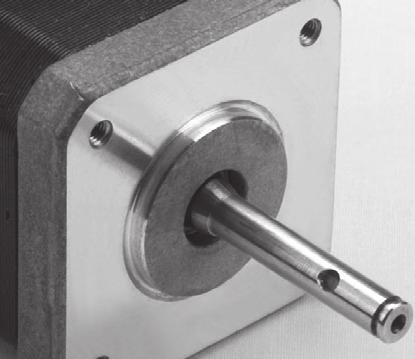
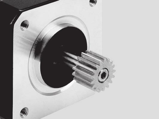
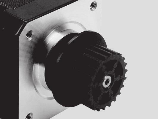
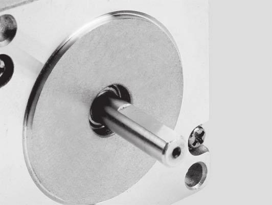

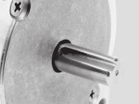
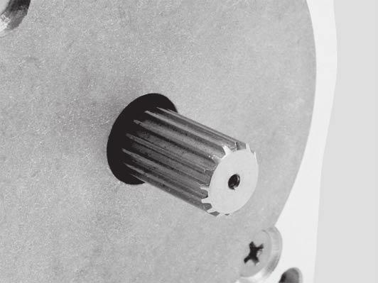
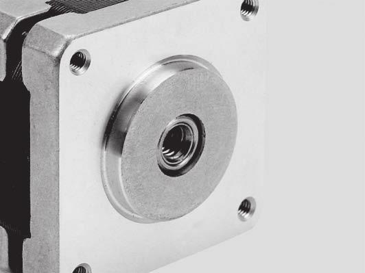

64 onfigurations Besides all standard motors above, we also provide all kinds of customized motors per request Shaft onfiguration Introduction Quick Selection -phase Stepper Motors -phase Stepper Motors UStepper Motors onfigurations ross Drilled Shaft Gear Plastic Pulley Single Flat Double Flat Key Way Knurl Hobbed Gear Screw Hollow Shaft Dowel Worm Shaft Hollow Shaft onnection onfiguration Encoder Option Gearbox Option Brake Option Integrated ead Wire ead Wire with onnector onnector with harness
65 Accessory Flange Demension Model Application of screw Maximum oad Scope Of Application AMJZ7-9N(kgf) NEMA7 M(X) AMJZ7-9N(kgf) NEMA7 Ø Flange Demension K -Ø + AMJZ7- K-K ± Ø + Mounting Surface AMJZ- -M 8± K K -ر 8± -M Ø - -8 Ø ± AMJZ7- K-K ± Mounting Surface Ø + 8± K -M K 8± -Ø + Model Application of screw Maximum oad Scope Of Application AMJZ- 9N(kgf) NEMA/NEMA(-phase) M(X) AMJZ- 9N(kgf) NEMA/NEMA(-phase) K K 7± 7± Ø97 ± K-K Instructions for use: reducing mechanical noise 7± Ø8 + + Install motor -ر Ø8 + -R AMJZ- 7± K K 7± K-K Introduction Quick Selection -phase Stepper Motors -phase Stepper Motors UStepper Motors onfigurations
66 Glossary Introduction Quick Selection -phase Stepper Motors -phase Stepper Motors UStepper Motors onfigurations Absolute Position Position referenced to a fixed zero or home position Absolute Programming A positioning coordinate reference wherein all positions are specified relative to some reference or home position; this is different from incremental programming where distances are specified relative to the current position Ambient Temperature The temperature of the medium immediately surrounding a device Amplifier Electronic device that converts command signals (analog or digital) to high power voltages and currents for the operation of the motor ASII American Standard ode for Information Interchange; this code assigns a number to each numeral and letter of the alphabet allowing information to be transmitted between machines as a series of binary numbers Axial Play(End play) The axial shaft displacement due to a reversal of an axial force on the shaft Baud Rate The number of binary bits transmitted per second for serial communications such as RS- Bi-level Drive (Dual Voltage Drive) A driver where two levels of voltage are used to drive a step motor; a high (over drive) voltage is applied to the winding each time it is switched on; the high voltage stays on until the current reaches a predetermined level; the high voltage is turned off after a time period determined experimentally or by sensing winding current; the low voltage maintains the desired current Bipolar Drive A drive that reverses the magnetic polarity of a pole by electronically switching the polarity of the current to the winding (+ or -); bipolar drives can be used with,, or 8 lead motors; with and 8 lead motors, bipolar drives are usually more efficient than unipolar drives and generally produce more torque Brushless Servo Drive A servo drive used to control a permanent magnet synchronous A motor hopper Drive A step motor drive that uses switching amplifiers to control motor current lass B Insulation Specifies motor insulation that is rated for operation up to lass H Insulation Specifies motor insulation that is rated for operation up to 8 losed oop A system that uses some form of feedback device to monitor the system output; the signal from the device is used to correct any errors between actual and demanded output ogging Term used to describe uneven velocity in motors usually at low speeds ommutation Refers to the action of steering currents or voltage to the proper motor phases to produce optimum motor torque In brush type motors, commutation is done electromechanically via the brushes and commutator In brushless motors, commutation is done by the switching electronics using rotor position information typically obtained from hall sensors, tachometers, resolvers or encoders ontroller (Step Motor) A system consisting of a D power supply and power switches plus associated circuits to control the switches in the proper sequence Damping An indication of the rate of decay of a signal to its steady state value; related to settling time Dead Band A range of input signals for which there is no system response Detent Torque The maximum torque required to slowly rotate a step motor shaft with no power applied to the windings; this applies only to permanent magnet or hybrid motors; the leads are separated from each other Drive (PWM) A motor drive utilizing Pulse-Width Modulation techniques to control current to the motor; typically a high efficiency drive that can be used for high response applications Drive (Servo) A motor drive that utilizes motor position feedback with a control loop for accurate control of motor position and/or velocity Drive (Stepper) An electronic package to convert digital step and direction inputs to currents to drive a step motor Duty ycle The percentage of ON time vs OFF time; a device that is always on has a % duty cycle; half on and half off is a % duty cycle
67 Dynamic Braking A passive technique for stopping a permanent magnet brush or brushless motor; the motor windings are shorted together through a resistor, which results in a motor braking with an exponential decrease in speed Encoder A device used to translate motion into electrical signals used to provide position information; often used as a position/motion feedback device in closed loop systems Encoder Marker Pulse A once-per-revolution signal that is provided by some incremental encoders to specify a reference point within that revolution End Play The axial shaft motion due to the reversal of an axial force acting on a shaft with axial clearance or low axial pre-load Following Error The positional error during motion between a load s actual position and the commanded position Friction - oulomb A resistance to motion between non-lubricated surfaces; this force remains constant with velocity Friction - Viscous A resistance to motion between lubricated surfaces; this force is proportional to the relative velocity between the surfaces Hall Sensors A feedback device built into a motor used by a servo amplifier to electronically commutate the motor Holding Torque (Static Torque) The maximum restoring torque that is developed by the energized motor when the shaft is slowly rotated by external means Hybrid Step Motor A type of step motor comprising a permanent magnet and variable reluctance stator and rotor structures; it uses a double salient pole construction Hysteresis (Positional) The difference between the step positions when moving W and the step position when moving W; a step motor may stop slightly short of the true position thus producing a slight difference in position W to W I/O (Inputs/Outputs) The reception and transmission of information between control devices; I/O has two distinct forms: Digital - switches, relays, etc which are either in an On or Off state; Analog a continuous signal such as speed, temperature, low, etc Idle urrent Reduction Reduction of phase current to a step motor when no motion is required Indexer An electronic control device that sends pulse and direction signals for use by a step motor driver Inductance (Mutual) The property that exists between two current carrying conductors or coils when magnetic lines of flux from one link with those of the other Inductance (Self) The constant by which the rate of change of the coil current must be multiplied to give the selfinduced counter EMF Inertia Measure of resistance of an object to changes in velocity; the larger the inertia, the more torque required to accelerate and decelerate the load Inertial Match Ratio of reflected load inertia to motor inertia Instantaneous START/STOP Rate The maximum switching rate that an unloaded step motor will follow without missing steps when starting from rest or stopping from moving /R Drive A drive that uses external resistance to allow a higher voltage than that of a voltage drive; / R drives have better performance than voltage drives, but have less performance and efficiency than a chopper drive oop, PID A high performance control loop that uses Proportional, Integral and Derivative type control parameters oop, Position A feedback control loop in which the controlled parameter is motor position oop, Velocity A feedback control loop in which the controlled parameter is velocity Maximum Reversing Rate The maximum stepping rate at which an unloaded motor will reverse direction of rotation without missing steps Maximum Slew Rate The maximum stepping rate at which a step motor with no load will run and remain in synchronism Microstepping A technique in which motor steps are electronically divided by the drive into smaller steps; the most common microstep resolutions are, and steps per full step, but many resolutions ranging from to microsteps per full step are available Introduction Quick Selection -phase Stepper Motors -phase Stepper Motors UStepper Motors onfigurations 7
68 Introduction Quick Selection -phase Stepper Motors -phase Stepper Motors UStepper Motors onfigurations Open Frame Drive Refers to amplifiers where a separate D power source must be provided to the unit Open-oop A system with no feedback; most step motor systems are run in this mode Oscillator A device that is used to produce pulses for driving a step motor at a preset speed Overshoot The amount a motor shaft rotates beyond the commanded stopping position Packaged Drive Refers to amplifiers where the power supply is included in the enclosure and /VA is used to power the unit Permanent Magnet Step Motor A step motor having a permanent magnet rotor and wound stator Pull-In Rate (Response Rate) The maximum switching rate at which an unloaded motor can start without losing step positions Pull-In Torque The maximum torque load at which a step motor will start and run in synchronism with a fixed frequency stepping rate without losing step positions Pull-out Torque The maximum torque load that can be applied to a motor running at a fixed stepping rate while maintaining synchronism; any additional load torque will cause the motor to stall or miss steps Pulse Rate The rate at which successive steps are initiated or the windings switched; the pulse rate divided by the resolution of the motor/drive combination (in steps per revolution) equals the rotational speed of the motor in revolutions per second PWM (Pulse Width Modulation) A method of controlling motor voltage and current used in servo and step motor drivers Radial Play (Side play) The side-to-side movement of the shaft due to clearances between the shaft and bearing, bearing to housing, and bearing internal clearance for ball and roller bearings Ramping The acceleration and deceleration of a motor; may also refer to the change in frequency of the step pulse train Rated Torque The torque producing capability of a motor at a given speed; this is the maximum continuous torque the motor can deliver to a load Regeneration The action during deceleration, in which the motor acts as a generator and takes kinetic energy from the load, converts it to electrical energy, and returns it to the amplifier Repeatability The degree to which the positioning accuracy for a given move performed repetitively can be duplicated Resolution The smallest positioning increment that can be achieved; frequently defined as the number of steps or feedback units required for a motor s shaft to rotate one complete revolution Resonance The effect of a periodic driving force that causes a large amplitude increase at a particular frequency Response Rate (Pull-In Rate) The stepping rate an unloaded motor can follow from a standing start without missing steps Ringing Oscillation of a system following a sudden change in state RS-, RS-/8 Serial communication hardware definitions Serial Port A digital data communications port that uses a serial bit stream for data transfer Servo Amplifier/Servo Drive An electronic device that converts a control signal into a current that is fed into the motor windings to produce torque in the motor Servo System A feedback control system for mechanical motion in which the controlled output is position or velocity; servo systems are closed loop systems Settling Time The elapsed time starting the instant the rotor reaches the commanded step position and the oscillations settle to within a specified displacement band around the final position 8
69 Si MOONS Simple Indexer operating environment; sequences for machine operation are programmed by the use of point and click instructions Slew The portion of a move made at a constant nonzero velocity Stall Torque (holding or static) The torque available from a motor at stall or zero rpm Step Angle The nominal angle through which the step motor shaft rotates between adjacent step positions Step or Stepping Rate (Speed) The number of steps a shaft rotates during a specified time interval Step-to-step Accuracy (relative accuracy) The maximum error that occurs between any adjacent step, expressed as a percentage of one full step Switching Amplifier A device that switches a high voltage on and off to control current; some amplifiers (PWM types) switch at a constant frequency and adjust duty cycle to control current, others have a fixed off time and adjust the frequency Switching Sequence (Energizing Sequence) The sequence and polarity of voltages applied to coils of a step motor that result in a specified direction of rotation Thermal Time onstant The time required for the motor winding to reach % of its final temperature Thermal Resistance The resistance to the flow of energy between two surfaces of the same body or different bodies; thermal resistance = degrees /watt in the winding Torque The rotary equivalent of force; equal to the product of the force perpendicular to the radius of motion and distance from the center of rotation to the point where the force is applied Torque onstant A number representing the relationship between motor input current and motor output torque, usually expressed in units of torque/amp Torque Displacement urve The holding (restoring) torque plotted as a function of rotor angular displacement with the motor energized Torque Gradient (Stiffness) The ratio of the change in holding torque to a particular change in shaft position when the motor is energized Torque Ripple The cyclical variation of generated torque given by the product of motor angular velocity and number of commutator segments Torque-to-inertia Ratio Ratio of a motor s torque divided by the motor s rotor inertia; the higher the ratio, the higher the acceleration may be Unipolar Drive The motor phase winding current is switched in one direction only; the polarity of the applied voltage to each winding is always the same; unipolar drives require or 8 lead motors Variable Reluctance Step Motor (V/R) A step motor having a wound stator or stators with salient poles working with a soft iron rotor having salient poles on the periphery Velocity The change in position as a function of time; velocity has both magnitude and direction Viscous Damping A damper that provides a drag or friction torque proportional to acceleration; a quality used to damp unwanted oscillations of a step motor Voltage Drive A drive operated at the minimum voltage required to safely limit motor current; motors used with voltage drives produce less torque at higher speeds than when used with /R or chopper drives Wave Drive Energizing the phases one at a time; driving the motor one phase or winding at a time Introduction Quick Selection -phase Stepper Motors -phase Stepper Motors UStepper Motors onfigurations 9
70 onversion Factors ength Introduction Quick Selection -phase Stepper Motors -phase Stepper Motors UStepper Motors onfigurations Force A Torque A Inertia A A B g kgf oz lb Newton g kgf, oz lb -- 8 Newton B Nm Ncm mnm kgm kgcm gcm oz-in lb-ft lb-in Nm --,, Ncm mnm kgm ,, kgcm , gcm 98E E- 88 oz-in lb-ft 8 8, lb-in, 8 -- B kgm kgcm gcm oz-in oz-in-sec lb-in lb-in-sec lb-ft lb-ft-sec (slug ft ) kgm --,,,,7, kgcm --, E- gcm E E- 88E-7 7E- 78E-8 oz-in 8E E- oz-in-sec 7 7 7, lb-in 9 9, lb-in-sec,,,, lb-ft,, lb-ft-sec (slug ft ) B mm cm m inch feet mm cm m, inch -- 8 feet Multiply "A" units by conversion factor to obtain "B" units,,, 7, 9, -- 7
7-7 8 Fax: +8 ()7-7 8 Beijing Branch Office Room 8, Tower B, hina Electronics")
-89 998 Wuhan Branch Office Room, World Trade Tower, No8 Jiefang Avenue, Jianghan District, Wuhan PRhina Tel: +8 ()7-8 87 Fax: +8 ()7-8 8 heng Du Branch Office Room 97, Western Tower, 9,")
9 887 Ningbo Branch Office Room 9, Block B, Taifu Plaza,No Jiangjia Road Jiangdong District Ningbo, PR hina Tel: +8 () 7-87 79 Fax: +8 () 7-87 Guangzhou Branch Office Room, Tower B, hina")
 PTE TD Ubi Avenue #8- Vertex Singapore 888 Tel: + 98 Fax: + 8 APPIED MOTION PRODUTS, IN Westridge Dr Watsonville, A 97, USA Tel: + 8 7 + 8 9 MOONS' INDUSTRIES EUROPE SR Via Torri")
71 Headquarters SHANGHAI AMP&MOONS' AUTOMATION O,TD No 8 Mingjia Road Industrial Park North Minhang District Shanghai 7, PR hina Tel: +8()- 88 Fax: +8()-9 88 Web: wwwmoonsindustriescom ama-info@moonscomcn Shenzhen Branch Office Room 9, /F, Kerry enter,no 8 Renminnan Road Shenzhen 8 P Rhina Tel: +8 ()7-7 8 Fax: +8 ()7-7 8 Beijing Branch Office Room 8, Tower B, hina Electronics Plaza, Danling Street, Haidian District, Beijing 8, PR hina Tel: +8 () 87 Fax:+8 () 8779 Qingdao Branch Office Room, Zhuoyue Tower, No Fengcheng Road, Shibei District, Qingdao P Rhina Tel: +8 () Fax: +8 () Wuhan Branch Office Room, World Trade Tower, No8 Jiefang Avenue, Jianghan District, Wuhan PRhina Tel: +8 () Fax: +8 ()7-8 8 heng Du Branch Office Room 97, Western Tower, 9, th Section of South People Road, Wuhou District, hengdu, PR hina Tel: +8 ()8 88 Fax:+8 ()8 88 Xi'an Branch Office Room, Tower D, Wangzuo International ity, Tangyan Road, Xi an 7, PR hina Tel: +8 ()9 887 Fax:+8 ()9 887 Ningbo Branch Office Room 9, Block B, Taifu Plaza,No Jiangjia Road Jiangdong District Ningbo, PR hina Tel: +8 () Fax: +8 () 7-87 Guangzhou Branch Office Room, Tower B, hina Shine Plaza, 9 inhe Xi Road, Tianhe District, Guangzhou, PR hina Tel: +8 () 8 Fax:+8 () 8 MOONS' INDUSTRIES (AMERIA), IN North Prospect Avenue, Itasca, I USA Tel: Fax: MOONS' INDUSTRIES (SOUTH-EAST ASIA) PTE TD Ubi Avenue #8- Vertex Singapore 888 Tel: + 98 Fax: + 8 APPIED MOTION PRODUTS, IN Westridge Dr Watsonville, A 97, USA Tel: MOONS' INDUSTRIES EUROPE SR Via Torri Bianche n 87 Vimercate (MB) Italy Tel: +9 9 Fax: IN ENGINEERING, IN Vineyard Blvd, Morgan Hill, A 97 Tel: Fax: ama-info@moonscomcn MOONS' INDUSTRIES JAPAN O, TD Room, F, Shin Yokohama Koushin Building, --, Shin-Yokohama, Kohoku-ku, Yokohama, Kanagawa, -, Janpan Tel: +8 () 7788 Fax: +8 () 7787 Service enter HINA / ST PRINT / TH / SEP / 7 NO A
PKP Series Standard Type and High-Resolution Type with Electromagnetic Brake
 High-Resolution Type Frame Size mm, 5. mm High- -phase Stepping s - A new highresolution addition to the PKP Series. With a basic step angle of., high resolution is combined with increased stopping accuracy.
5-Phase Stepper Motor
 Ordering Information Application model: Standard shaft type, Hollow shaft type, Shaft type+ A 8K M 5 6 6 B Motor type Motor phase Rated current Max. Holding torque Shaft type Motor length : provides single
Pluse Input Type Integrated Step Motor STM-R Series
 Pluse Input Type Step Motor Series Step Motor The is an integrated Drive+Motor, fusing step motor and drive technologies into a single device, offering savings on space, wiring and cost over conventional
56 mm sq. (2.20 inch sq.)
") 56 mm sq. (2.2 inch sq.) 1.8 /step RoHS Bipolar winding, Lead wire type Unipolar winding, Lead wire type p. 68 Customizing Hollow Shaft modification Decelerator Encoder Varies depending on the model number
56 mm sq. (2.2 inch sq.) 1.8 /step RoHS Bipolar winding, Lead wire type Unipolar winding, Lead wire type p. 68 Customizing Hollow Shaft modification Decelerator Encoder Varies depending on the model number
SR4. 2 Phase Step Motor Drive. User Manual Rev AMP & MOONS Automation
 SR4 2 Phase Step Motor Drive User Manual Rev. 1.1 AMP & MOONS Automation Contents 1 Introduction...3 1.1 Overview...3 1.2 Features...3 1.3 Block diagram...4 2 Mounting the Drive...4 3 Connections...5 3.1
SR8. 2 Phase Step Motor Drive. User Manual Rev AMP & MOONS Automation
 SR8 2 Phase Step Motor Drive User Manual Rev. 1.1 AMP & MOONS Automation Contents 1 Introduction...3 1.1 Overview...3 1.2 Features...3 1.3 Block diagram...4 2 Mounting the Drive...4 3 Connections...5 3.1
Hybrid Stepper Motors
 DINGS Electrical & Mechanical Co., Ltd 3 Quality Performance Flexibility Price WHO IS DINGS? DINGS is a premier supplier of rotary and linear step motors. Based in the greater Shanghai, China area, we
Ø 68 mm to ø 115 mm. Material: Weight: Shaft Loads: Enclosure Rating: Connection Options. Cable: Cable Glands:
 Electrical Specifications Code: Incremental Resolution: Up to 10,000 ppr (pulses per revolution) Supply Voltage: ** 4.5 Vdc min. to 30 Vdc max. (45 ma max. - no load) Low: 500 mv max. at 10 ma Voltage:
Ø 68 mm to ø 115 mm. Material: Weight: Bearing Life: Shaft Loads: Operating Temp.: Storage Temp.: Shock: Vibration: Bump: Humidity: Enclosure Rating:
 , EN 60079 Electrical Specifications Code: Incremental Resolution: Up to 10,000 ppr (pulses per revolution) Supply Voltage: ** 4.5 Vdc min. to 30 Vdc max. (45 ma max. - no load) Low: 500 mv max. at 10
High-Efficiency AR Series. RK Series /0.72 /Geared. CRK Series. RBK Series. CMK Series. 2-Phase Stepping Motors A-278.
 A Stepping Motors Stepping Motors Introduction A-2 Introduction AC Power Supply Input Stepping Motor and Driver Packages A-17 DC Power Supply Input Stepping Motor and Driver Packages Stepping Motors (Motor
Stepper Motors ver ver.5
 A Stepper s Stepper s A-1 Overview... A-2 Overview and... A-15 & Stepper and RK Series A-16 RK... A-47... A-51 Stepper Series A-52 Stepper Series A-8 See Full Product Details Online www.orientalmotor.com
Data Sheet. Size 1 and 2 Stepper Motors. 7.5 stepper motors Size 1 (RS stock no ) Size 2 (RS stock no ) Data Pack B
 Size 2 (RS stock no ) Data Pack B") Data Pack B Issued November 005 1504569 Data Sheet Size 1 and Stepper Motors 7.5 stepper motors Size 1 (S stock no. 33-947) Size (S stock no. 33-953) Two 7.5 stepper motors each with four 1Vdc windings
Data Pack B Issued November 005 1504569 Data Sheet Size 1 and Stepper Motors 7.5 stepper motors Size 1 (S stock no. 33-947) Size (S stock no. 33-953) Two 7.5 stepper motors each with four 1Vdc windings
SR8-Plus 2 Phase Step Motor Drive
 2 Phase Step Motor Drive User Manual Rev. 1.1 AMP & MOONS Automation Contents 1 Introduction... 3 1.1 Overview...3 1.2 Features...3 1.3 Block diagram...4 2 Mounting the Drive... 4 3 Connections... 5 3.1
56 mm sq inch sq.
 Stepping Motors 56 mm sq. 2.2 inch sq. 1.8 /step Unipolar winding Lead wire type Bipolar winding Lead wire type P.4 Unipolar winding Lead wire type Model number Holding torque at Rated current Wiring Winding
PKG-341-MBC08-PS-CBL System Diagram and Specifications
 PKG-341-MBC8-PS-CBL System Diagram and Specifications Included Components: 34Y112S-LW8-MS Stepper Motor MBC82561 Stepper Driver PSA8V4A-1 Power Supply CBL-18AWG-4C-1-MS Motor Cable WIR-17-18-YEL Power
42 mm sq inch sq.
 tepping Motors 42 mm sq. 1.65 inch sq. 1.8 /step lim form winding Lead wire type winding Lead wire type Model number Holding torque at Rated current Wiring Winding Mass Rotor inertia 2-phase energization
Stepper Motors. PKP Series
 Stepper Series Stepper Series Stepper Series -Phase High Torque ow Vibration Bipolar ( lead wires) and unipolar ( or lead wires) are available. ( type mm/flat type is bipolar wiring only.) / /System Configuration/
PKP Series. High-Torque 2-Phase Stepper Motors. Standard Type with Encoder High-Resolution Type with Encoder. Features.
 High- 2-Phase Stepper s PKP Series Standard Type with High-Resolution Type with High- 2-Phase Stepper s - A new encoder motor addition to the PKP Series. motors contribute to the improvement of equipment
SHINANO KENSHI CORP. STEPPING MOTORS DC BRUSHLESS MOTORS DC SERVO MOTORS
 SHINANO KENSHI CORP. STEPPING MOTORS DC BRUSHLESS MOTORS DC SERVO MOTORS ISO-9000 & ISO-14000 Certified Since its inception in 1918, Shinano Kenshi Co., Ltd. of Japan has found innovative and creative
Material: Weight: Shaft Loads: Enclosure Rating: Cable: Cable Glands:
 Oil & Gas / Heavy Industry Type 2REX-A EN 60079 Electrical Specifications Code: Incremental Resolution: 1 to 10,000 ppr (pulses per revolution) Supply Voltage: ** 4.5 Vdc min. to 30 Vdc max. (45 ma max.
2: A, B 3: A, B, Z 4: A, A _, B, B _ 6: A, A _, B, B _, Z, Z _
 Diameter mm Shaft Type/Hollow Type/Built-In Type Incremental Rotary Encoder Features Diameter mm flange type Suitable for measuring angle, position, revolution, speed, acceleration and distance Power supply:
5-Phase Stepping Motor and Driver Package RK Series
 RoHS-Compliant -Phase Stepping Motor and Driver Package RK Series Standard Type PN Geared Type TH Geared Type Harmonic Geared Type RoHS-Compliant -Phase Stepping Motor and Driver Package RK Series The
Product Manual. 42BYGH40(M)-160-4A NEMA 17 Bipolar 5.18:1. Planetary Gearbox Stepper
-160-4A NEMA 17 Bipolar 5.18:1. Planetary Gearbox Stepper") Product Manual 42BYGH40(M)-160-4A NEMA 17 Bipolar 5.18:1 Planetary Gearbox Stepper Phidgets - Product Manual 42BYGH40(M)-160-4A NEMA 17 Bipolar 5.18:1 Planetary Gearbox Stepper Phidgets Inc. 2011 Contents
Product Manual 42BYGH40(M)-160-4A NEMA 17 Bipolar 5.18:1 Planetary Gearbox Stepper Phidgets - Product Manual 42BYGH40(M)-160-4A NEMA 17 Bipolar 5.18:1 Planetary Gearbox Stepper Phidgets Inc. 2011 Contents
Type 2REX-A. Oil & Gas / Heavy Industry
 Oil & Gas / Heavy Industry Type 2REX-A EN 60079 Electrical Specifications Code: Incremental Resolution: 1 to 10,000 ppr (pulses per revolution) Supply Voltage: ** 4.5 Vdc min. to 30 Vdc max. (45 ma max.
High quality nut and screw materials are precisely formed to reduce backlash, increase life, support maximum force, and increase efficiency
 Linear Actuators owerlustechnology...03 Model Number System...04 Basic Styles Lead & Linear Travel...05 Optional Construction & Modifications...06 Size 8 -.8 - Lx08HY Series...07 Size -.8 - LxHS Series...0
TurboDisc Stepper Motors
 TurboDisc Stepper Motors P43 P532 P31 P11 P1 The TurboDisc provides exceptional dynamic performance unparalleled by any other stepper on the market. The unique thin disc magnet enables finer step resolutions
QMOT QSH5718 MANUAL. QSH mm 2.8A, 0.55Nm mm 2.8A, 1.01Nm mm 2.8A, 1.26Nm mm 2.8A, 1.
 QMOT STEPPER MOTORS MOTORS V 2.3 QMOT QSH5718 MANUAL + + QSH-5718-41-28-055 57mm 2.8A, 0.55Nm -51-28-101 57mm 2.8A, 1.01Nm -56-28-126 57mm 2.8A, 1.26Nm -76-28-189 57mm 2.8A, 1.89Nm + + TRINAMIC Motion
HSI Stepper Motor Theory
 HI tepper Motor Theory Motors convert electrical energy into mechanical energy. A stepper motor converts electrical pulses into specific rotational movements. The movement created by each pulse is precise
MANTECH ELECTRONICS. Stepper Motors. Basics on Stepper Motors I. STEPPER MOTOR SYSTEMS OVERVIEW 2. STEPPING MOTORS
 MANTECH ELECTRONICS Stepper Motors Basics on Stepper Motors I. STEPPER MOTOR SYSTEMS OVERVIEW 2. STEPPING MOTORS TYPES OF STEPPING MOTORS 1. VARIABLE RELUCTANCE 2. PERMANENT MAGNET 3. HYBRID MOTOR WINDINGS
OPERATING MANUAL. Table of Contents. 5 Phase Stepping Motor and Driver. PN Geared Type HP Precautions...Page 2
 HP-4117-3 5 Phase Stepping and UPK W Series PN Geared Type OPERATING MANUAL C Table of Contents 1. Precautions...Page 2 2. Product Verification...Page 3 3. Names and Function of Parts... Page 4 4. Installation...Page
ILE2K661PC1A1 brushless dc motor V- EtherNet/IP interface - L = 174 mm- 18:1
 Characteristics brushless dc motor 24..48V- EtherNet/IP interface - L = 174 mm- 18:1 Main Range of product Product or component type Device short name Motor type Number of motor poles 6 Network number
PMX TM. Series Stepper Motor. Selection Guide. with P-Series Stepper Positioning Drives
 PMX TM Series Stepper Motor Selection Guide with P-Series Stepper Positioning Drives Kollmorgen: Removing the Barriers of Design, Sourcing, and Time. At Kollmorgen, we know that OEM engineers can achieve
St epping Mot or s C-i ORIENTAL MOTOR GENERAL CATALOG 2009/2010
 C-i ORIENTAL MOTOR GENERAL CATALOG 29/21 C Introduction C-2 Stepping Motor and Driver Packages AC Input Stepping Motor and Driver Packages DC Input Stepping Motors AC Input AS Series C-14 DC Input ASC
Namiki Precision Jewel Co.,Ltd. Applications
 amiki Precision Jewel Co.,Ltd Applications Selection Guide Figure 1 Figure Figure 4 Figure 2 Unit conversion table ISO Certification ew grades For Servo amiki had developed new line-up for suitable applications
QMOT Motor QSH4218 Manual 42mm QMOT motor family
 QMOT Motor QSH4218 Manual 42mm QMOT motor family Trinamic Motion Control GmbH & Co. KG Sternstraße 67 D 20357 Hamburg, Germany http://www.trinamic.com QSH4218 Manual (V1.03 /13-November-2007) 2 Table of
Lexium integrated drives
 Description ILp for CANopen, PROFIBUS DP, RS ILE with brushless DC motor Description ILE comprise control electronics with a fieldbus interface for CANopen DS, PROFIBUS DP or RS and a brushless DC motor.
QMOT STEPPER MOTORS MOTORS
 QMOT STEPPER MOTORS MOTORS V 1.08 QMOT QSH6018 MANUAL + + QSH-6018-45-28-110 60mm 2.8A, 1.10 Nm -56-28-165 60mm 2.8A, 1.65 Nm -65-28-210 60mm 2.8A, 2.10 Nm + + -86-28-310 60mm 2.8A, 3.10 Nm TRINAMIC Motion
Primer. Stepper Motors
 Primer Stepper Motors Phidgets - Primer Manual Motors Phidgets Inc. 2011 Contents 4 Introduction 5 Types of Stepper Motors 7 Controlling the Stepper Motor 9 Selecting a Gearbox 10 Glossary of Terms Introduction
AS Series. RK Series. UMK Series ASX Series 0.36 /0.72. CRK Series. CMK Series 1.8. RBK Series. PK Series 1.
 A Stepping Motors Stepping Motors Introduction A-2 Introduction AC Input Stepping Motor and Driver Packages DC Input Stepping Motor and Driver Packages Stepping Motors (Motor Only) A-269 A-24 High Efficiency
Lexium integrated drives
 Description ILp for DeviceNet, EtherCAT, Modbus TCP, ILE with brushless DC motor Description ILE comprise control electronics with a fieldbus interface for DeviceNet, EtherCAT, Modbus TCP or and a brushless
Before Using a Stepping Motor
 Stepping & Driver Packages 2-Phase Stepping Driver Controllers 2-Phase Full/Half Indexer out C-295 Stepping Installation Direction of Mounting can be mounted freely in any direction as shown below. Regardless
Motors electrical specifications, connection and protection class
 s electrical specifications, connection and protection class The measured values and the unipolar and bipolar connections of stepper motor. The measures set forth in the stepping motors tables in this
The STH is a mid-range speed and torque gear reducer that
 STH-SERIES The STH is a mid-range speed and torque gear reducer that sets a new standard for rotary positioning performance at an exceptional price point. A SHIMPO ABE planetary gearbox is the interface
ILE1F661PC1A0 brushless dc motor V - CANopen DS301 interface - L = 122 mm - w/o gearbox
 Characteristics brushless dc motor 24..36 V - CANopen DS301 interface - L = 122 mm - w/o gearbox Main Range of product Product or component type Device short name Motor type Number of motor poles 6 Network
Step Motor. Mechatronics Device Report Yisheng Zhang 04/02/03. What Is A Step Motor?
 Step Motor What is a Step Motor? How Do They Work? Basic Types: Variable Reluctance, Permanent Magnet, Hybrid Where Are They Used? How Are They Controlled? How To Select A Step Motor and Driver Types of
Power in new dimensions
 NEW FAULHABER BXT Power in new dimensions WE CREATE MOTION EN Angaben zu Lebensdauer sowie weitere technische Erläuterungen 1 FAULHABER BXT Today, you don't find visionary designs in Hollywood, but rather
Technical Reference H-37
 tepper Technical Reference H-37 tructure of tepper The figures below show two cross-sections of a.72 stepper motor. The stepper motor consists primarily of two parts: a stator and rotor. The rotor is made
LS100 Series Positioning Tables
 LS100 Series Positioning Tables User s Guide A N A H E I M A U T O M A T I O N 4985 East Landon Drive Anaheim, CA 92807 e-mail: info@anaheimautomation.com (714) 992-6990 fax: (714) 992-0471 website: www.anaheimautomation.com
Prepared By: Ahmad Firdaus Bin Ahmad Zaidi
 Prepared By: Ahmad Firdaus Bin Ahmad Zaidi A stepper motor is an electromechanical device which converts electrical pulses into discrete mechanical rotational movements. Stepper motor mainly used when
RoHS-Compliant Brushless Motor Systems FBL Series. Features
 Speed Control Systems RoHS-Compliant Brushless Motor Systems FB Series The FB Series consists of a high performance, compact, brushless motor and driver. This product is available with 75 W (1/1 HP) and
SERIE 59S. Rear clamp. Frontal clamp INCREMENTAL HOLLOW SHAFT ENCODER FOR INDUSTRIAL APPLICATIONS SIN/COS
 INCREMENTAL HOLLOW SHAFT ENCODER FOR INDUSTRIAL APPLICATIONS Resolution up to 2.048 pulses per turn Shaft fixing through front or rear clamp External diameter 58 mm Hollow shaft Ø 10, 12 or 14 mm Protection
ILE2T661PB1A3 brushless dc motor V - Modbus TCP interface - L = 174 mm - 54:1
 Characteristics brushless dc motor 24..48 V - Modbus TCP interface - L = 174 mm - 54:1 Product availability : Non-Stock - Not normally stocked in distribution facility Price* : 1540.00 USD Main Range of
Features Block Diagram Specifications Typical Wiring Diagram Connection and Adjustment Locations...3 4
 SUESTEP STP-DV-4035 MICOSTEPPING DIVE CHAPTE 3 In This Chapter... Features.......................................32 Block Diagram...................................32 Specifications...................................33
AK-G/AK-GB/AK-R/AK-RB Series
 4mm/ 6mm/ 85mm Geared type/geared+rake built-in type 6mm Rotary actuator type/ Rotary actuator+rake built-in type Features Compact design and light weight with high accuracy, speed and torque Cost-effective
ILE1F661PB1A0 brushless dc motor V - CANopen DS301 interface - L = 122 mm - w/o gearbox
 Characteristics brushless dc motor 24..36 V - CANopen DS301 interface - L = 122 mm - w/o gearbox Product availability : Stock - Normally stocked in distribution facility Price* : 840.00 USD Main Range
Completely free from the Concern of Loss of Position (Alarm Feneration when Step-Out) Perfect Positiooning and Completion (Positioning Completion
 Perfect Positiooning and Completion (Positioning Completion") Completely free from the Concern of Loss of Position (Alarm Feneration when Step-Out) Perfect Positiooning and Completion (Positioning Completion Signal Generation) Don t Care what the Phase of Motor is
Completely free from the Concern of Loss of Position (Alarm Feneration when Step-Out) Perfect Positiooning and Completion (Positioning Completion Signal Generation) Don t Care what the Phase of Motor is
gear reduction. motor model number is determined by the following: O: Single 1: Double Motor Characteristics (1-99) Construction
 Construction") TEP OPERATIO & THEORY 1 KC tepping Motor Part umber. oncumulative positioning error (± % of step angle).. Excellent low speed/high torque characteristics without 1. tepping motor model number description
TEP OPERATIO & THEORY 1 KC tepping Motor Part umber. oncumulative positioning error (± % of step angle).. Excellent low speed/high torque characteristics without 1. tepping motor model number description
43M4 n n n n n n. 43L4 n n n n n n. E43M4 n n n n n n. Bipolar 5 VDC 12 VDC. 550 ma 1.3 A 21.9 Ω 3.8 Ω mh mh W Total.
 HAYD: 2 756 744 KERK: 6 2 629 4 Series: Double Stack Stepper Motor Linear Actuator Haydon 4 Series Double Stack hybrid linear actuators offer greater performance. Double Stack Captive Shaft The versatile
BMS Series. DC Brushless Torque Motors. Slotless, brushless stator design provides zerocogging torque for unsurpassed velocity control
 BMS Series Rotary Motors BMS Series DC Brushless Torque Motors Slotless, brushless stator design provides zerocogging torque for unsurpassed velocity control Smoother velocity than with standard DC brushtype
ILA2D572TC1F0 integrated drive ILA with servo motor V - DeviceNet - indus connector
 Characteristics integrated drive ILA with servo motor - 24..48 V - DeviceNet - indus connector Main Range of product Product or component type Device short name Motor type Number of motor poles 6 Phase
Hybrid Control System, Alpha Step
 B Hybrid Control System, Alpha Step Hybrid Control System B-1 Overview... B-2 Overview Hybrid Control System Battery-Free, Absolute Sensor Equipped AZ Series... B-16 Electric Linear Slides EZS Series AZ
MOONS SM servo motors offer a great combination of Power, Precision and Value:
 MOONS SM Series of servo motors has been expanded and improved. The SM Series now includes a variety of standard windings, more feedback options, and more connection options. Some ratings have increased,
Stepper Motors. Wide Range of Motor Sizes! Motor Wiring D-1
 Stepper Motors Frame Sizes From NEMA 11 to 34 Wide Range of Motor Sizes! All models shown smaller than actual size. Motor Wiring OMEGA offers a robust line of 2-phase biploar step motors ranging in frame
Identifying the Motorized RGS part number codes when ordering
 RGS04 Motorized with 28000 Series Size11 DS RGS04 Linear Rail for Hybird 28000 Series Size 11 Double Stacks and RGS04 for 43000 Series Size 17 Single and Double Stacks (See Page 4) RGS04 Linear Rail with
ZETA advanced microstep drive. Microstepping systems - the next generation... Automation. Quicker settling following a speed change
 ZETA-2 advanced microstep drive Microstepping systems - the next generation... The new ZETA series drives from Parker represent a true revolution in microstep drive design. Incorporating breakthrough techniques
ILE1B661PC1A1 brushless dc motor V - Profibus DP interface - L = 174 mm - 18:1
 Characteristics brushless dc motor 24..36 V - Profibus DP interface - L = 174 mm - 18:1 Product availability : Non-Stock - Not normally stocked in distribution facility Price* : 1640.00 USD Main Range
Motor Only/Driver Only
 Stepper Motors A-. / / Only. /.7 /. /. /. /.7 /..7 /. /. / / Only.,.9.7,.. /.9.7 /. Page.,.9 A- A-7.7,. A- A- A- A-. /.9 Stepper Motors Technical reference Page H- Regulations
UNIT 7: STEPPER MOTORS
 UIT 7: TEPPER MOTOR 1 TEPPER MOTOR tepper motors convert digital information to mechanical motion. tepper motors rotate in distinct angular increments (steps) in response to the application of digital
High-Precision, Direct-Drive Linear Servo Systems
 High-Precision, Direct-Drive Linear Servo Systems (EM and LVD) pending The is a direct drive linear actuator servo system. Each complete system consists of a brushless linear servo motor, microprocessor-based
Please read Safety Considerations in operation manual before using. [Ai-M-42 Series] [Ai-M-56 Series] [Ai-M-60 Series] 67.5mm mm. 73.
![Please read Safety Considerations in operation manual before using. [Ai-M-42 Series] [Ai-M-56 Series] [Ai-M-60 Series] 67.5mm mm. 73.](/thumbs/87/97105400.jpg "Please read Safety Considerations in operation manual before using. [Ai-M-42 Series] [Ai-M-56 Series] [Ai-M-60 Series] 67.5mm mm. 73.") i- Series 2-Phase Closed-Loop Stepper otor Features inimal heat generating, high torque motor (control voltage 55V) Higher cost-efficiency compared to conventional servo motors vailable in motor frame
i- Series 2-Phase Closed-Loop Stepper otor Features inimal heat generating, high torque motor (control voltage 55V) Higher cost-efficiency compared to conventional servo motors vailable in motor frame
QUESTION BANK SPECIAL ELECTRICAL MACHINES
 SEVENTH SEMESTER EEE QUESTION BANK SPECIAL ELECTRICAL MACHINES TWO MARK QUESTIONS 1. What is a synchronous reluctance 2. What are the types of rotor in synchronous reluctance 3. Mention some applications
QMOT Motor QSH4218 Manual 42mm QMOT motor family
 QMOT Motor QSH4218 Manual 42mm QMOT motor family Trinamic Motion Control GmbH & Co. KG Sternstraße 67 D 20357 Hamburg, Germany Phone +49-40-51 48 06 0 FAX: +49-40-51 48 06 60 http://www.trinamic.com INFO@TRINAMIC.COM
Kollmorgen Stepper Motor Overview
 Kollmorgen Stepper Motor Overview K O L L M O R G E N S T E P P E R M O T O R O V E R V I E W Kollmorgen offers a comprehensive range of stepper motor products including continous torque, high torque and
The STH is a mid-range speed and torque gear reducer that
 -SERIES The is a mid-range speed and torque gear reducer that sets a new standard for rotary positioning performance at an exceptional price point. A SHIMPO ABLE planetary gearbox is the interface between
Memorial University of Newfoundland Faculty of Engineering and Applied Science
 Memorial University of Newfoundland Faculty of Engineering and Applied Science ENGR 1040 Mechanisms & Electric Circuits Prof. Nicholas Krouglicof Laboratory Exercise ML2: Stepper Motor Torque Testing Unipolar
Low-Speed. Constant Speed Motors. Standard AC Motors A-203. Standard AC Motors Introduction. Low-Speed Synchronous Motors.
 Standard C Constant Speed Low-Speed Synchronous Standard C Introduction Induction Reversible Electromagnetic Brake V Series Clutch & Brake Synchronous Low-Speed Synchronous Low-Speed Synchronous Watertight,
PKP Series with PLE Gearhead
 High-Torque 2-Phase Stepper Motors PKP Series with PLE Gearhead High-Torque Combination Bipolar 2-phase Stepper Motors with Neugart Planetary Gearheads Motor and Gearhead are Pre-assembled Short Delivery
RH Series. Features. Structure. High resolution High resolution of maximum 400,000 pulses/revolution ( /pulse) combining a HarmonicDrive.
 combining a HarmonicDrive.") RH Series The RH series includes compact and high-torque DC servo actuators with a high rotational accuracy combining a speed reducer HarmonicDrive for precision control and a DC servo motor. A combination
RH Series The RH series includes compact and high-torque DC servo actuators with a high rotational accuracy combining a speed reducer HarmonicDrive for precision control and a DC servo motor. A combination
MCR MOTOR MR1107/MR1108 MR1107/MR1108. High reliability, low cost, compatible design. Advanced manufacturing techniques
 High reliability, low cost, compatible design MR117/MR118 Alternative Housing and gear made from anti-aging material are used in manufacturing MR 117/118 stepper motor. Therefore, the motors can stand
CVK Series. 1.8, 0.72 and 0.36 Stepper Motor and Driver Package. DC Input
 .8,.7 and.36 Stepper Motor and Driver Package CVK Series DC Input Compact, standardized drivers, combined with performance driven high torque stepper motors, for the optimum results. mm, 8 mm, 35 mm, mm,
MOTORS. Part 2: The Stepping Motor July 8, 2015 ELEC This lab must be handed in at the end of the lab period
 MOTORS Part 2: The Stepping Motor July 8, 2015 ELEC 3105 This lab must be handed in at the end of the lab period 1.0 Introduction The objective of this lab is to examine the operation of a typical stepping
SMH60S AAK-3LKH SMH60S AAK-3LKN SMH60S ABK-3LKH
 FEATURES 60mm Frame Size 220VAC Power Rating up to 400 Watts Rated Torque up to 1.27 Nm Rated Speed of 3000 RPM Brake Option Available 2500PPR Incremental Encoder Totally Enclosed, Non-Ventilated IP65
DD Motor Designation MDM. D D None 34 D NO H. DD Motor Designation. External Diameter Rated Troque Encoder Type
 Motor esignation XGT Servo System(X/XM) 90 / 91 Motor esignation MM None 34 NO H Motor Type Input Power Supply Rated Speed Shape of Shaft End : MOTOR None : 220 : 300rpm H : Hollow Type : 200rpm G : 150rpm
SMH80S AAK-3LKH SMH80S ABK-3LKH SMH80S AAK-3LKN
 FEATURES DESCRIPTION CUSTOM ORDER LAYOUT 80mm Frame Size Power Rating up to 1000 Watts Rated Torque up to 3.18 Nm Rated Speed of 3000 RPM Brake Option Available 2500PPR Incremental Encoder Totally Enclosed,
BLU Series. RoHS-Compliant. Brushless DC Motor and Driver Package. Features
 RoHS-Compliant Brushless DC Motor and Driver Package BLU Series The BLU Series combines a brushless DC motor and a panel-installation type driver, enabling speed control via simple wiring and easy operation.
Step Motors & Drives. Hybrid Step Motors
 The typical step motor system consists of a step motor and a drive package that contains the control electronics and a power supply. The drive receives step and direction signals from an indexer or programmable
M, N and A Series Brushless Servo Motors
 www.applied-motion.com M, N and A Series Brushless Servo Motors Applied Motion s M Series, N Series, and A Series brushless servo motors provide extremely high performance in one of the industry s most
SMH80S AAK-3AKH SMH80S ABK-3AKH
 FEATURES DESCRIPTION 120 VAC 80mm Frame Size Power Ratings from 750-1000 Watts Rated Torque of 338-450 oz-in Maximum Speed of 5000 RPM Brake Option Available 2500 PPR Incremental Encoder IP65 Protection
HPCMAX HPCMAX203892
 DC Motors 13mm Dia. Motor ø1.5mm Motor Shaft 1.2 Watt - Precious Metal Bushes X Motors 1.2 W ø13 mm Motor Data HPCMAX203889 HPCMAX203892 Values at nominal voltage 1 Nominal voltage V 6.0 12.0 2 No load
User Manual. Model P403. High Performance Microstepping Driver
 User Manual Model P403 High Performance Microstepping Driver 1. General The P403 is a high performance microstepping driver based on the most advanced technology in the world today. It is suitable for
Improved Speed Control Made Simple. Stepper Motors. CVK Series SC Type
 Improved Speed Control Made Simple Stepper Motors CVK Series SC Type The simple motor and driver configuration makes speed control possible. Control is easy. Select speeds, and turn the start input ON
DMX-A2-DRV Integrated Advanced Step Motor Driver
 DMX-A2-DRV Integrated Advanced Step Motor Driver DMX-A2-DRV Manual page 1 rev 3.10 COPYRIGHT 2008 ARCUS, ALL RIGHTS RESERVED First edition, May 2008 ARCUS TECHNOLOGY copyrights this document. You may not
COLLEGE OF ENGINEERING DEPARTMENT OF ELECTRICAL AND ELECTRONICS ENGINEERING QUESTION BANK SUBJECT CODE & NAME : EE 1001 SPECIAL ELECTRICAL MACHINES
 KINGS COLLEGE OF ENGINEERING DEPARTMENT OF ELECTRICAL AND ELECTRONICS ENGINEERING QUESTION BANK SUBJECT CODE & NAME : EE 1001 SPECIAL ELECTRICAL MACHINES YEAR / SEM : IV / VII UNIT I SYNCHRONOUS RELUCTANCE
NX Series. Tuning-Free AC Servo Motor Unit
 Tuning-Free AC Servo Motor Unit NX Series An AC servo motor unit that is capable of high accuracy control with easy operation. Smooth operation can be achieved in high inertia loads or belt drive applications
9. Define: Pull out torque of stepper motor?
 UNIT II STEPPING MOTORS PART - A 1. Define: Stepper motor? (June 14) Stepper motor is a motor which rotates step by step and not continuous rotation. When the stator is excited using a DC supply the rotor
SMH60S-0040 Servo Motor
 FEATURES 120-220 VAC 400 W Power Rating Rated Torque of 1.27 Nm Maximum Speed of 6200 RPM 2500 PPR Incremental Encoder IP65 for Body, IP54 Shaft Seal 60mm Frame Size CE Certified DESCRIPTION The SMH60S
High Performance: EPR Series
 High Performance: EPR Series GAM can. If you don t see exactly what you need, let us know. We can modify the EPR Series gearboxes to meet your needs. Page 4 provides a list of commonly requested modifications
DHANALAKSHMI SRINIVASAN COLLEGE OF ENGINEERING AND TECHNOLOGY MAMALLAPURAM, CHENNAI
 DHANALAKSHMI SRINIVASAN COLLEGE OF ENGINEERING AND TECHNOLOGY MAMALLAPURAM, CHENNAI -603104 DEPARTMENT OF ELECTRICAL AND ELECTRONICS ENGINEERING QUESTION BANK VII SEMESTER EE6501-Power system Analysis
BLH. 24 VDC Input 15W / 30W / 50W / 100W BLH
 BLH 24 VDC Input 15W / 30W / 50W / 100W BLH BLH BLH BLH BLH 2 3 System Configuration Geared Type/Combination Type Parallel Shaft Gearhead/Round Shaft Type The system configuration shown above is an example.
DC BRUSHLESS MOTOR DRIVER CONTROL TYPE
 DRIVER CONTROL TYPE BLDC MOTOR TYPICAL PERFORMANCE MODEL voltage (V) output ( W) (A) Speed (RPM) (kgf-cm) Rating (Kg) Flange Housing FBD60-N012005 12 5 0.7 1500/3000 0.33/0.16 cont 0.5 60 60 x 53 FBD60-N012015