XCell Fury Extreme Assembly Manual
|
|
|
- Cecil Wade
- 6 years ago
- Views:
Transcription


1 XCell Fury Extreme Assembly Manual Version 1.0 Created: 11/14/2006 Copyright Miniature Aircraft US
2 For More Information contact: Miniature Aircraft USA Long Acres Drive Sorrento, FL USA Phone Fax Page 2 of 138 Copyright Miniature Aircraft USA Created: 11/14/2006
3 Table Of Contents REVISIONS TO THIS MANUAL... 6 ERRATA... 6 I. KIT INTRODUCTION... 7 R/C HELICOPTER SAFETY... 7 GUIDELINES FOR SAFE R/C HELICOPTER FLIGHT... 7 X-CELL LIMITED WARRANTY... 8 WARRANTY PROCEDURES... 8 X-CELL EXTREME WARRANTY REGISTRATION... 8 II. KIT PREREQUISITES... 9 SUPPLIES NEEDED FOR ASSEMBLY... 9 Adhesives Used... 9 TOOLS NEEDED FOR ASSEMBLY ADDITIONAL COMPONENTS NEEDED III. KIT ASSEMBLY PROCESS ASSEMBLY TIPS FASTENER GUIDE STEP #1 GEAR RATIOS A) Gear Ratio - Bag #1A Kit Specific :18 Ratio :45 Ratio...16 STEP #2 LEFT FRAME A) Main Frame Components - Bag #2A B) Frame Fasteners - Bag #2B B.1 Assemble Left Frame Part B.2 Assemble Left Frame Part C) Drive Train Components - Bag #2C C.1 Install Drive Train Components...24 D) Constant Drive - Bag #2D D.1 - Assemble Constant Drive Unit D.2 Install Main Shaft/Collars D.3 Install Constant Drive D.4 Install Left Gear Ratio Plate...31 E) Clutch Assembly - Bag #2E E.1 - Assemble Clutch E.2 - Install Clutch Assembly...34 STEP #3 RIGHT FRAME A) Right Frame - Bag #3A B) Right Frame Components - Bag #3B B.1 Assemble Right Frame B.2 Install Right Frame B.3 - Install Right Ratio Plate B.4 Install Landing Gear Mounts...45 C) Control Bellcranks - Bag #3C C.1 Assemble Aileron/Pitch Bellcranks C.2 Install Aileron/Pitch Bellcranks C.3 - Assemble Elevator Bellcrank C.4 - Install Elevator Bellcrank...50 Created: 11/14/2006 Copyright Miniature Aircraft USA Page 3 of 138
4 3C.5 - Assemble Rudder Bellcrank C.6 - Install Rudder Bellcrank...52 STEP #4 FRAME ASSEMBLY A) Chassis Components - Bag #4A B) Engine Components - Bag #4B B.1 Prepare Engine B.2 Install Engine Mounts B.3 Install Engine...59 C) Landing Gear - Bag #4C C.1 Assemble/Install Landing Gear/Frame Bottom Plate...60 D) Fan Shroud Mounts - Bag #4D D.2 Assemble/Install Fan Shroud/Mounts D.3 Install Muffler...64 STEP #5 FUEL TANK A) Fuel Tank - Bag 5A A.1 - Assemble Fuel Tank A.2 - Install Fuel Tank...70 STEP #6 SWASHPLATE/WASHOUT MIXER A) Swashplate - Bag #6A Kit Specific A.1 - Assemble Swashplate A.2 - Install Swashplate 140 Kit...74 B) Washout Mixer - Bag #6B B.1 - Assemble Washout Mixer B.2 - Install Washout Mixer B.3 Assemble Swashplate Control Rods B.4 Install Swashplate Control Rods...79 STEP #7 CONTROL SYSTEM/CANOPY A) Servo Mounts - Bag #7A A.1 Install Servos/Radio Gear...81 B) Ball Links - Bag #7B C) Control Rods - Bag #7C C.1 Assemble Servo Control Rods...85 D) Servo Supports - Bag #7D D.1 Assemble/Install Servo Wheels D.2 Install Servo Control Rods D.3 Install Servo Supports...91 E) Canopy Mounts - Bag #7E E.1 Assemble Canopy Knobs...92 F) Canopy Box Contents F.1 Prepare Canopy...94 STEP #8 ROTOR HEAD A) Head Block - Bag #8A A.1 - Head Block Assembly...96 B) Blade Grips - Step #8B B.1 Assemble Bell Mixer B.2 Install Bell Mixers...99 C) Head Axle Components - Bag #8C C.1 - Blade Arm Assembly C.1 Assemble Blade Arms C.2 Install Blade Arms D) Flybar - Bag #8D D.1 Assemble/Install Flybar Control System D.2 Assemble/Install Flybar Bell Links D.3 Install Flybar D.4 Install Flybar Paddles D.5 Install Rotor Head Page 4 of 138 Copyright Miniature Aircraft USA Created: 11/14/2006
5 STEP #9 TAIL ROTOR ASSEMBLY A) Tail Rotor Hub - Bag #9A A.1 Assemble Tail Rotor Hub A.2 Install Tail Rotor Blades B) Tail Rotor Pitch Yoke - Bag #9B B.1 Assemble TR Pitch Yoke C) Tail Rotor Transmission - Bag #9C C.1 Assemble T/R BellCrank C.2 Install T/R BellCrank C.3 Install T/R Pitch Yoke STEP #10 LOCATE TAIL BOOM COMPONENTS A) Tail Boom Components - Bag # STEP #11 TAIL BOOM ASSEMBLY A) Tail Boom Mounts - Bag #11A A.2 Install T/R Transmission A.3 Install Vertical Fin Mount/Fin A.4 Install Horizontal Fin Mount/Fin A.5 Install Tail Rotor A.6 Install Front Tail Boom Mount B) Tail Rotor Pushrod Components - Bag #11B B.1 Assemble/Install T/R Pushrod Guide B.2 Install Tailboom B.3 Assemble T/R Pushrod B.4 Install T/R Pushrod C) Tail Boom Support Components - Bag #11C C.1 Assemble Tail Boom Supports C.2 Install Tail Boom Supports C.3 Install Rotor Blades C.4 Install Canopy Created: 11/14/2006 Copyright Miniature Aircraft USA Page 5 of 138
6 Revisions to this Manual R1.0 10/01/06 Revisions for final kitting modifications 11/10/06 Revisions to main rotor blade arm bearing order For the most current version of this manual, please refer to visit the Extreme helicopter kit and download the assembly manual Errata Page 6 of 138 Copyright Miniature Aircraft USA Created: 11/14/2006
7 I. Kit Introduction R/C Helicopter Safety A radio controlled model helicopter is a technically complex device that must be built and operated with care. It is also a fascinating and challenging part of the R/C sport, the mastery of which is very rewarding. A model helicopter must be built exactly in accordance with the building instructions. The kit manufacturer has spent much time and effort refining his product to make it reliable in operation and easy to build. The essentially bolt together construction can proceed quite rapidly, giving the builder a strong sense of accomplishment that encourages hasty progress from one construction phase to the next, so that the completed model can be more quickly seen and enjoyed. It is essential to recognize and guard against this tendency. Follow building instructions exactly. Vibration and stress levels are high and all fasteners and attachments must be secure for safe operation. Note that this is the first use of the word SAFETY in these comments. Previously the kit manufacturer s efforts to ensure reliable operation were mentioned. That is ALL that he can do. Safe operation is the responsibility of the builder/flyer and starts with careful construction and continues with selection and installation of reliable radio equipment and engine. The need for safety is nowhere greater than at the flying field. A number of guidelines for safe flight have been developed by experienced flyers and are set down here. It is urged that they be read, understood and followed. Guidelines for Safe R/C Helicopter Flight Fly only at approved flying fields and obey field regulations. Follow frequency control procedures. Interference can be dangerous to all. Know your radio. Check all transmitter functions before each flight. Be aware that rotating blades are very dangerous and can cause serious injury. Never fly near or above spectators or other modelers. If a beginner, get help trimming the model first and flight training later. Don t track the main blades by holding the tail boom. This is a temptation to builders who cannot hover yet and is very dangerous. Follow all recommended maintenance procedures for model, radio and engine. WARNING! This helicopter is not a toy, but a complex flying machine that must be assembled with care by a responsible individual. Failure to exert care in assembly, or radio or accessory installation, may result in a model incapable of safe flight or ground operation. Rotating components are an ever present danger and source of injury to operators and spectators. Since the manufacturer and his agents have no control over the proper assembly and operation of his products, no responsibility or liability can be assumed for their use. Created: 11/14/2006 Copyright Miniature Aircraft USA Page 7 of 138
8 X-CELL Limited Warranty The warranty covers defects in material or workmanship or missing components to the original purchaser for 30 days from the date of purchase. Miniature Aircraft, USA will replace or repair, at our discretion, the defective or missing component. Defective components must be returned to us prior to replacement. Any part, which has been improperly installed, abused, crash damaged or altered by unauthorized agencies, is not covered. Under no circumstances will the buyer be entitled to consequential or incidental damages. The components used in this kit are made form special materials designed for special applications and design strengths. We recommend that all replacement parts be original parts manufactured by Miniature Aircraft, USA, to ensure proper and safe operation of your model. Any part used which was manufactured by any firm other than Miniature Aircraft, USA, VOIDS all warrantees of this product by Miniature Aircraft, USA. Warranty Procedures Mail all warranty information within 15 days of original purchase date. If service is required, send the component in question (if not missing) together with a photocopy of your bill of sale and an accurate description of the problem and part. Ship components fully insured and prepaid. Miniature Aircraft, USA is not responsible for any shipping damages. We will, at our discretion, notify you of any costs involved, or ship it COD. You are required to pay all postage, shipping and insurance charges. X-Cell Extreme Warranty Registration Please print or type, filling in the information listed below and mail immediately Model No: Serial No: Price paid: Owners name: Age Address: City: State: Phone: Zip: Purchased from: Dealer s address Comments: MINIATURE AIRCRAFT USA Long Acres Drive Sorrento, FL USA Phone (352) FAX (352) Page 8 of 138 Copyright Miniature Aircraft USA Created: 11/14/2006


9 II. Kit Prerequisites In order to assemble this kit, you will need a number of additional supplies and tools to ensure the best final result. They are as follows: Supplies Needed for Assembly Blue Thread Lock Red Thread Lock Green Thread Lock Oil Grease Adhesives Used Slow Cyanoacrylate JB Weld Created: 11/14/2006 Copyright Miniature Aircraft USA Page 9 of 138
 8.0mm wrench 5.5mm wrench 4.")
10 Tools Needed for Assembly M5 Nut Driver M5.5 Nut Driver M7 Nut Driver M4 Nut Driver 1.5mm allen driver 2.0mm allen driver 2.5mm allen driver 3.0mm allen driver Needle Nose Pliers Phillips Screwdriver #1 Flat Screwdriver 2.5mm Razor Knife (Xacto) 8.0mm wrench 5.5mm wrench 4.0mm wrench Page 10 of 138 Copyright Miniature Aircraft USA Created: 11/14/2006


11 Additional Components Needed Gyro Servo Servos 4 each Receiver Switch Battery NiCad NiMH LiPo 1700mah or more Motors: OSMax YS.91SZH.91ST4 Gyro Heading Hold Created: 11/14/2006 Copyright Miniature Aircraft USA Page 11 of 138


12 Main Rotor Blades mm 5mm blade bolt 14mm blade root Tail Rotor Blades mm Mufflers: Hatori SB16/SB17FH Muscle Pipe/MP2 Page 12 of 138 Copyright Miniature Aircraft USA Created: 11/14/2006
13 III. Kit Assembly Process Assembly Tips Please note that this assembly manual consists of a photographic journal of the steps necessary to construct this helicopter. The builder is encouraged to pay close attention to the "building notes" and other details noted in the pictures and to carefully review all the photo s in a given step. The placement of a given part may be better understood when viewing another view of the assembly. Follow the order of assembly. The instructions have been organized into major sections and have been developed in such a way that each step builds upon the work done in the previous step. Changing the order of assembly may result in unnecessary steps The photos in this manual are organized within each step to correspond with the order of assembly. The sequence of the photos within a step is from top to bottom and from left to right. Clean all metal parts: All of the steel parts in this kit are coated with a lubricant to prevent them from rusting. This coating can interfere with the adhesives and thread locks needed for assembly. Use a solvent such as alcohol or acetone to clean the various metal parts, especially threads Use thread lock as indicated. Model helicopters are subject to vibration and failing to use thread lock on any non-locking assembly may result in a part becoming loose or falling off Sand sharp edges on any frame plate that Velcro or wires may rub against to prevent them from being damaged over time by vibration Make sure every bearing runs smoothly after component assembly. If it does not find out why. A rough running bearing will fail prematurely. As a general rule any bolt that threads into a metal part should have thread lock applied and any screw or bolt that threads into a plastic part should have adhesive applied Assembly sections contain the following content: o The contents of each bag o An overview of part relationships o Assembly overview Photographs will contain assembly icons that indicate use of thread lock, adhesive or lubricant as needed. If an assembly has more than one of the same part number, application of thread lock, adhesive or lubricant will apply to all of the same numbered parts in that photograph Examples of the icons are as follows: Thick Adhesive Blue Thread Lock Red Thread Lock Green Thread Lock Lubricant Grease Fastener Guide The next page contains a list of all of the threaded fasteners in this kit. They will print at actual size. If it is not clear what the part number of a fastener is, simply find the fastener on the chart and match its part number and description Created: 11/14/2006 Copyright Miniature Aircraft USA Page 13 of 138

14 Part # Description Actual Size 0027 M2.2 x 9.5 phillips screw M2.2 x 13 phillips M2.9 x 9.5 phillips screw M2.9 x 9.5 phillips flat head screw M2.5 x 10 phillips bolts M2.5 x 12 phillips bolt M2 x 10 slotted bolt M3.5 x 25 socket set screw M2 x 10 socket bolt M3 x 3 socket set screw M3 x 5 socket set screw M3 x 16 socket set screw M4 x 4 socket set screw M4 x 6 socket set screw M2.5 x 6 socket bolt M3 x 6 socket bolt M3 x 8 socket bolt M3 x 10 socket bolt M3 x 8 button head M3 x 12 socket bolt M3 x 14 socket bolt M3 x 25 socket bolt M3 x 30 socket bolt M4 x 12 socket bolt M3 x 35 socket bolt M4 x 14 socket bolt M4 x 16 socket bolt M5 blade bolt M5 flanged bolt M3 x 8 flat head bolt M3 x 6 flat head bolt M3 x 10 hex head bolt M3 x 18 phillips bolt M3 x 22 phillips bolt M3 x 16 button head Page 14 of 138 Copyright Miniature Aircraft USA Created: 11/14/2006

15 Step #1 Gear Ratios A) Gear Ratio - Bag #1A Kit Specific 8:18 Ratio # Left Motor Mount 8:18 # Right Motor Mount 8:18 # Graphite Ratio Plates 8:18 # Motor Shims # tooth main gear Building Notes Locate Bag 1A. If you purchased the 8.18 kit it will contain parts specific to the 8.18 gear ratio. Verify that they are correct. The gear ratio plates will be etched with the actual gear ratio and marked as left and right. Make sure that the marked ratio matches on both plates and that there is a left and right plate. The motor mounts will have round holes machined in the wide part of the engine mount. If they are square, then the mounts are for the 8.45 kit. In addition, there will be two shims that go between the motor and the mounts. The main gear in the 8.18 kit will contain 90 teeth. Set these parts aside to be used in future steps. Created: 11/14/2006 Copyright Miniature Aircraft USA Page 15 of 138

16 8:45 Ratio # Left Motor Mount 8:45 # Right Motor Mount 8:45 # Graphite Ratio Plates 8:45 # tooth main gear Building Notes Locate Bag 1A. If you purchased the 8.45 kit it will contain parts specific to the 8.45 gear ratio. Verify that they are correct. The gear ratio plates will be etched with the actual gear ratio and marked as left and right. Make sure that the marked ratio matches on both plates and that there is a left and right plate. The motor mounts will have square holes machined in the wide part of the engine mount. If they are round, then the mounts are for the 8.18 kit. In addition, there will be two shims that go between the motor and the mounts. The main gear in the 8.45 kit will contain 93 teeth. Set these parts aside to be used in future steps. Page 16 of 138 Copyright Miniature Aircraft USA Created: 11/14/2006

17 Step #2 Left Frame A) Main Frame Components - Bag #2A # Main Shaft # Velcro 12 # Left Main Frame # Horizontal Front Channel # Radio Plate # Tank Plate # Vertical Front Channel # Vertical Rear Channel Building Notes Locate Bag 2A which contains the major frame components for the left frame assembly These parts will be used in the following steps. Created: 11/14/2006 Copyright Miniature Aircraft USA Page 17 of 138

18 B) Frame Fasteners - Bag #2B # mm Hex Spacer # Graphite Tubes # Switch Plate # mm Hex Spacer # Bellcrank Spacer # Frame Spacer # Fan Shroud Mount # Front Canopy Standoff #0169 Bellcrank Stud #0019 M3 Locknut 8 each # Anti-rotation # Gyro Mount # Rudder Bellcrank Stud # M3 x 6 Socket Bolt 8 each #0061 M3 x 8 Socket Bolt 5 each #0064 M3 x 8 Button Head # M3 x 16 Button Head #0089 M3 x 10 Hex Head #0079 M3 x 35 Socket Bolt #0032 M2.9 x 9.5 Phillips Screw Page 18 of 138 Copyright Miniature Aircraft USA Created: 11/14/2006
 #0089 #115-58 #115-10 #115-12 #115-62 #0079 (2) Created: 11/14/2006 Copyright Miniature Aircraft USA Page 19")
19 2B.1 Assemble Left Frame Part 1 Parts Relationship #0032 (2) # # ONLY #0169 # #0019 #0061 # (2) # # # # # #0061 # # # # # #0019 #0061 #0019 # #0061 # (2) #0089 # # # # #0079 (2) Created: 11/14/2006 Copyright Miniature Aircraft USA Page 19 of 138


20 2B.1.a 2B.1.b 2B.1.c # # # # # B.1.d 2B.1.e 2B.1.f # # #0089 # #0079 2B.1.g # Page 20 of 138 Copyright Miniature Aircraft USA Created: 11/14/2006


21 2B.2 Assemble Left Frame Part 2 Parts Relationship # (2) # # #0019 #0019 # #0019 #0019 #0064 #0064 # B.2.a 2B.2.b 2B.2.c # # #0064 #0019 Created: 11/14/2006 Copyright Miniature Aircraft USA Page 21 of 138


22 2B.2.d 2B.2.e 2B.2.f # # ONLY #0019 2B.2.G 2B.2.H 2B.2.I # Location #0019 #0019 #0019 #0061 #0061 # B.2.J #0061 2B.2.K # #00032 # Page 22 of 138 Copyright Miniature Aircraft USA Created: 11/14/2006

23 C) Drive Train Components - Bag #2C #120-9 Front Input Shaft # mm collar # tooth bevel gear # Lower Main Shaft Block # Upper Main Shaft Block #120-8 Center Main Shaft Block #0051 M3 x 3 Socket Set Screws 4 each # M3 x 6 Socket Bolt #0061 M3 x 8 Socket Bolt 5 each #0063 M3 x 10 Socket Bolt Created: 11/14/2006 Copyright Miniature Aircraft USA Page 23 of 138

")


24 2C.1 Install Drive Train Components Parts Relationship #0061 #0061 #0051 (4) # # #232 #120-8 #120-9 # #0061 (2) # #0061 2C.1.a 2C.1.b 2C.1.c # # #0051 #120-8 #0051 # # Page 24 of 138 Copyright Miniature Aircraft USA Created: 11/14/2006


25 2C.1.d 2C.1.e Align set screw with Flat on Shaft Tighten against bearing Created: 11/14/2006 Copyright Miniature Aircraft USA Page 25 of 138

26 D) Constant Drive - Bag #2D # tooth Crown Gear # Crown Gear Mounting Base # Retaining Collar # Main Hub Unit # M14 x 0.1 Shim # M14 x 0.2 Shim #0088 M3 x 8 Flat head bolt 4 each # Teflon 0-ring # M3 x 6 Flat Head Bolt 8 each #0057 M4 x 4 Socket Set Screw # M2.5 x 6 Socket Bolt # M3 x 20 Steel Pin #0875 Mainshaft Collar Page 26 of 138 Copyright Miniature Aircraft USA Created: 11/14/2006

27 2D.1 - Assemble Constant Drive Unit Parts Relationship # # # (Qty 8) # # # #0057 # # for 8.18 # for 8.45 # # # # #0088 (Qty 4) Created: 11/14/2006 Copyright Miniature Aircraft USA Page 27 of 138


 Do")


28 2D.1.a 2D.1.b 2D.1.c # # # /93 # #0088 (4) 2D.1.d 2D.1.e 2D.1.f # # # (8) Do Not Overtighten Screws! # Twist to Insert! 2D.1.g 2D.1.h 2D.1.i # # # Page 28 of 138 Copyright Miniature Aircraft USA Created: 11/14/2006


 Created: 11/14/2006 Copyright Miniature")
29 2D.2 Install Main Shaft/Collars Parts Relationship # # #0875 # # #0057 #0875 # # #120-8 # D.2.a 2D.2.b #0875 (2) Building Notes note the positions of the bevels on the shaft collars. Note the orientation of the mainshaft. The holes on each end of the shaft are different. # # (2) Created: 11/14/2006 Copyright Miniature Aircraft USA Page 29 of 138


30 2D.3 Install Constant Drive 2D.3.a 2D.3.b 2D.3.c # #0057 Slightly Forward Building Notes Do not over tighten the set screw that captures the retaining pin Before tightening the lower main shaft collar, move the t/r pinion gear forward by 1/8. Using two fingers hold pressure between the lower collar and the constant drive. Now tighten the lower retaining collar Do not over tighten the bolts in the collars! Tighten until the bolt seats on the collar and then tighten an additional ¼ turn. 2D.1.d 2D.1.e Building Notes reposition the t/r pinion gear so that it s centered on the crown gear. Tighten the two set screws in the pinion gear. Make sure the one on the shaft flat is centered on the flat Do not over-tighten as this may distort the gear. Re-Center Page 30 of 138 Copyright Miniature Aircraft USA Created: 11/14/2006

31 2D.4 Install Left Gear Ratio Plate 2D.4.a Building Notes the ratio plates are marked as left and right versions. Make sure you install the correct plate on the correct side. #0061 #0063 Created: 11/14/2006 Copyright Miniature Aircraft USA Page 31 of 138

32 E) Clutch Assembly - Bag #2E # Tooth Clutch Bell Unit #121-7 Clutch Unit # M6 O-Ring #0063 M3 x 10 Socket Bolt 4 each #0003 M3 Washer - Large #0000 M3 Washer Small Page 32 of 138 Copyright Miniature Aircraft USA Created: 11/14/2006


33 Parts Relationship #0063 #0063 # #0003 #0003 # #0061 #119-18/19 L #0009 #121-7 #0063 #0063 #0063 2E.1 - Assemble Clutch 2E.1.a 2E.1.b # # Building Notes Do not lubricate the o- ring #121-7 Created: 11/14/2006 Copyright Miniature Aircraft USA Page 33 of 138


34 2E.2 - Install Clutch Assembly 2E.2.a 2E.2.b 2E.2.c #0003 #0063 #0009 Building Notes Do not tighten the four clutch bolts until gear spacing has been set. Set the gear spacing by running a small strip of paper between the gears as shown. While the paper strip is between the gears, tighten the four clutch bolts. Don t forget to use thread lock. Page 34 of 138 Copyright Miniature Aircraft USA Created: 11/14/2006

35 #0061 # # #0089 Created: 11/14/2006 Copyright Miniature Aircraft USA Page 35 of 138

36 # # #0064 #0079 #0032 #0061 #0063 #0063 #0061 # #0061 Page 36 of 138 Copyright Miniature Aircraft USA Created: 11/14/2006
37 Step #3 Right Frame A) Right Frame - Bag #3A # Main Frame - Right Created: 11/14/2006 Copyright Miniature Aircraft USA Page 37 of 138

38 B) Right Frame Components - Bag #3B #0003 M3 Washer Large # CNC Landing Gear Brackets # Lower Clutch Spacer #0169 Bellcrank Stud # Bellcrank Spacer #0009 M3 Washer Small # Upper Clutch Spacer #0034 M2.9 x 9.5 Phillips Flat Head Screw #0019 M3 Locknut 9 each # mm Hex Spacer # mm Hex Spacer # Front Canopy Stand Off #0065 M3 x 12 Socket Bolt 4 each # M3 x 6 Socket Bolt 1 #0061 M3 x 8 Socket Bolt 10 each #0063 M3 x 10 Socket Bolt #0089 M3 x 10 Hex Bolt Page 38 of 138 Copyright Miniature Aircraft USA Created: 11/14/2006
 #0061 #126-69 #0089 #0061 #0061 #0019 #0019 #0061 #115-35 #106-41 Created: 11/14/2006 Copyright Miniature Aircraft USA Page 39")
39 3B.1 Assemble Right Frame Parts Relationship #0169 #0169 #0061 #0034 (2) # # ONLY #0019 # # # Bellcrank Location 140 Bellcrank Location # #0019 # #0061 (2) #0061 # #0089 #0061 #0061 #0019 #0019 #0061 # # Created: 11/14/2006 Copyright Miniature Aircraft USA Page 39 of 138
 #0169 #0019")


40 3B.1.a 3B.1.b 3B.1.c # (4) #0169 #0019 # # # ONLY #0169 3B.1.d 3B.1.e 120 Bellcrank Location # Bellcrank Location Completed Outside View 140 Completed Inside View 140 Page 40 of 138 Copyright Miniature Aircraft USA Created: 11/14/2006


41 3B.2 Install Right Frame 3B.2.a Set Right Frame In Place 3B.2.b 3B.2.c 3B.2.d # #0089 #0034 3B.2.e 3B.2.f #0061 Building Notes Install the bolts through the frame channels with lock nuts. #0061 Make sure any threaded bolts that don t use lock nuts are installed with thread lock. #0019 #0019 Created: 11/14/2006 Copyright Miniature Aircraft USA Page 41 of 138

42 #0061 # #0061 #0061 # Page 42 of 138 Copyright Miniature Aircraft USA Created: 11/14/2006


")

43 3B.3 - Install Right Ratio Plate Parts Relationship #0003 #0003 #0063 #0063 # # # #119-18/19 R #0063 # #0061 #0009 # #0063 #0063 3B.3.a 3B.3.b 3B.3.c # #0003 (2) #119-18/19 R # #0063 (4) #0061 #0009 (2) # #0063 Created: 11/14/2006 Copyright Miniature Aircraft USA Page 43 of 138

44 3B.3.d Building Notes After the ratio plate is in place, first tighten the bolts around the outside of the plate. Then tighten the four bolts that attach the plate to the clutch assembly. Make sure all bolts are installed with thread lock. Page 44 of 138 Copyright Miniature Aircraft USA Created: 11/14/2006

")


45 3B.4 Install Landing Gear Mounts Parts Relationship #0063 # #0063 #0019 (2) #0019 (2) #0063 #0063 3B.4.a 3B.4.b 3B.4.c Created: 11/14/2006 Copyright Miniature Aircraft USA Page 45 of 138

46 C) Control Bellcranks - Bag #3C #0131 Plastic Bushing #0051 M3 x 3 Socket Set Screw # Elevator Frame Support # Brass Sleeve #0019 M3 Locknut #0159 M3 x 7 Ball Bearings 6 each #0113 M3 Double Ball # M3 Shim #0009 M3 Washer Small #0107 M3 x 6 Threaded Ball 5 each #0171 3mm Collar #0105 M3 x 4.5 Threaded Ball # Rudder Bellcrank #0636 M5 x 10 Flanged Bearings # Bellcrank 3 each #0061 M3 x 8 Socket Bolt 3 each Page 46 of 138 Copyright Miniature Aircraft USA Created: 11/14/2006


47 3C.1 Assemble Aileron/Pitch Bellcranks Parts Relationship #0159 #0107 #0167 #0159 #0171 #0051 #0107 3C.1.a 3C.1.b #0159 #0107 Created: 11/14/2006 Copyright Miniature Aircraft USA Page 47 of 138


48 3C.2 Install Aileron/Pitch Bellcranks 3C.2.a 3C.2.b #0171 #0051 Page 48 of 138 Copyright Miniature Aircraft USA Created: 11/14/2006

 #0159 (2) #0866-11 3C")

49 3C.3 - Assemble Elevator Bellcrank Parts Relationship #0105 #0113 #0131 #0009 # # #0167 #0061 (2) #0019 (2) #0159 (2) # C.3.a 3C.3.b #0159 (2) #0113 #0105 Created: 11/14/2006 Copyright Miniature Aircraft USA Page 49 of 138


 Page")

50 3C.4 - Install Elevator Bellcrank 3C.4.a 3C.4.b 3C.4.c #0009 #0131 # # C.4.d 3C.4.e 3C.4.f #0061 (2) #0019 (2) Page 50 of 138 Copyright Miniature Aircraft USA Created: 11/14/2006

")


51 3C.5 - Assemble Rudder Bellcrank Parts Relationship 3C.5.a #0105 #0636 #0636 (2) # # C.5.b # #0107 3C.5.c #0636 Created: 11/14/2006 Copyright Miniature Aircraft USA Page 51 of 138

52 3C.6 - Install Rudder Bellcrank 3C.6.a #0061 #0009 Page 52 of 138 Copyright Miniature Aircraft USA Created: 11/14/2006

53 Step #4 Frame Assembly A) Chassis Components - Bag #4A # Fan Tool #3933 Struts - White # Cooling Shroud # Base Plate # Skids Building Notes Locate Bag 4A which contains the lower frame components These parts will be used in the following steps. Created: 11/14/2006 Copyright Miniature Aircraft USA Page 53 of 138

54 B) Engine Components - Bag #4B # Inner Motor Mount # Cooling Fan # Upper Collet - YS # Dampers #546-5 Upper Collet OS #0332 M8 x 13 x 1 Shim Washer #546-6 Base Collet #0079 M3 x 35 Socket Bolt #0077 M3 x 30 Socket Bolt #0080 M4 x 14 Socket Bolt 4 each #0078 M4 x 12 Socket Bolt #0019 M3 Locknut 6 each #0003 M3 Washer Large 6 each #0063 M3 x 10 Socket Bolt #0067 M3 x 14 Socket Bolt 4 each Page 54 of 138 Copyright Miniature Aircraft USA Created: 11/14/2006


55 4B.1 Prepare Engine Parts Relationship Washer from engine #579-4 # (2) Nut From Engine #0332 #546-6 #546-5 OS # YS 4B.1.a 4B.1.b 4B.1.c #546-6 washer #579-4 Created: 11/14/2006 Copyright Miniature Aircraft USA Page 55 of 138


56 4B.1.d 4B.1.e 4B.1.f #546-5 OS small ledge # YS deep ledge #546-5 # #0332 4B.1.g 4B.1.h 4B.1.i # (2) Building Notes you should dial indicate the fan runout to less than.002 using a dial indicator as shown. Runout should be checked on both the face and the top edge of the fan hub. The collet system usually makes alignment fairly easy, however if you re having problems getting runout to an acceptable level, contact Miniature Aircraft by phone or via the support forum located on the website. Page 56 of 138 Copyright Miniature Aircraft USA Created: 11/14/2006

 #115-53 #0003 #0063 (2) #0077 #0019")
")

57 4B.2 Install Engine Mounts Parts Relationship #0079 #115-50/ # #0019 (2) #0078 (2) #0067 (2) #0019 #0077 #0003 (2) # #0003 #0063 (2) #0077 #0019 #0019 (2) #0080 (2) #0067 (2) #115-51/ # #0003 (2) #0079 4B.2.a 4B.2.b 4B.2.c #115-51/ # # #0077 (2) #0079 Created: 11/14/2006 Copyright Miniature Aircraft USA Page 57 of 138


58 4B.2.d 4B.2.e 4B.2.f #0079 #115-51/ #0067 # #0003 #0003 #115-50/ # #0067 #0019 #0019 #0019 (4) 4B.2.g Page 58 of 138 Copyright Miniature Aircraft USA Created: 11/14/2006


59 4B.3 Install Engine 4B.3.a 4B.3.b 4B.3.c # # Only 8.18 Only #0080 (2) #0079 (2) 4B.3.d 4B.3.e Building Notes There should be no more than.020 gap between the fan and clutch driver. Use the clutch gap tool as shown or feeler gauges. Push the motor against the guage before tightening the mount bolts. Created: 11/14/2006 Copyright Miniature Aircraft USA Page 59 of 138

 #3933 (2) #0019 (2) #0075 #122-39 Page 60 of 138 Copyright Miniature")
60 C) Landing Gear - Bag #4C # Skid Plugs White 4 each #0003 M3 Washer Large 4 each #0019 M3 Locknut # M4 x 6 Socket Set Screw 4 each #0075 M3 x 25 Socket Bolt 4C.1 Assemble/Install Landing Gear/Frame Bottom Plate Parts Relationship # (4) # (4) # #0075 #0003 (2) #3933 (2) #0019 (2) #0075 # Page 60 of 138 Copyright Miniature Aircraft USA Created: 11/14/2006


")


61 4C.1.a 4C.1.b 4C.1.c Drill with #29 Then with #42 Drill bits #3933 # # #3933 (2) 4C.1.d 4C.1.e 4C.1.f #0003 #0019 # mm 4C.1.g 4C.1.h 4C.1.i #0003 # (4) # (4) #0063 Created: 11/14/2006 Copyright Miniature Aircraft USA Page 61 of 138

62 D) Fan Shroud Mounts - Bag #4D #0032 M2.9 x 9.5 Phillips Screw # Fan Shroud Braces 3 each # Round Plastic Spacers 4 each # M3 x 6 Socket Bolt #0061 M3 x 8 Socket Bolt #0063 M3 x 10 Socket Bolt #0065 M3 x 12 Socket Bolt #0029 M2.2 x 13 Phillips Screw 5 each Page 62 of 138 Copyright Miniature Aircraft USA Created: 11/14/2006
 #3923-1 (2) #0063 #0065 #0063 #0060-1 #0548-5 #0060-1 #0029 (5) #0032")


63 4D.2 Assemble/Install Fan Shroud/Mounts Parts Relationship # # #0065 # (2) # (2) #0063 #0065 #0063 # # # #0029 (5) #0032 #0061 (2) # #0032 4D.2.a 4D.2.b # # # #0032 #0065 # #0063 Building Notes you may need to make adjustments to the fan shroud for carburetor clearance or for cylinder head or muffler mounts depending on your choices. Use a rotor grinder to remove material. Created: 11/14/2006 Copyright Miniature Aircraft USA Page 63 of 138


64 4D.2.d # # # #0061 #0032 #0063 #0063 # D.3 Install Muffler 4D.3.a 4D.3.b Trim Shroud Page 64 of 138 Copyright Miniature Aircraft USA Created: 11/14/2006

65 #0032 #0079 #0067 #0063 #0077 #0061 #0029 (5) #0063 #0065 # #0063 Created: 11/14/2006 Copyright Miniature Aircraft USA Page 65 of 138

66 #0065 #0077 #0063 # #0061 #0079 #0032 #0067 #0063 #0077 Page 66 of 138 Copyright Miniature Aircraft USA Created: 11/14/2006

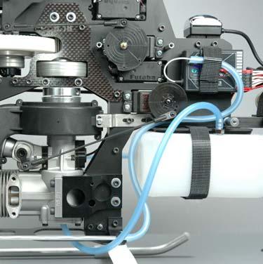
67 Step #5 Fuel Tank A) Fuel Tank - Bag 5A # Fuel Tank Pre-Drilled # Fuel Line #0013 M5 Hex Nut #0401 Clunk # fuel Pickup Tubing #0011 M5 x 10 Washer #0405 Fuel Vent # Fitting # Dual Sided Velcro Created: 11/14/2006 Copyright Miniature Aircraft USA Page 67 of 138


68 5A.1 - Assemble Fuel Tank Parts Relationship # #0409 5A.1.a #0401 # #0405 5A.1.b #0405 #0011 #0011 #0013 #0013 5A.1.c 5A.1.d # Page 68 of 138 Copyright Miniature Aircraft USA Created: 11/14/2006


69 5A.1.e 5A.1.f #0409 5A.1.g 5A.1.h #0409 Created: 11/14/2006 Copyright Miniature Aircraft USA Page 69 of 138


70 5A.2 - Install Fuel Tank 5A.2.a 5A.2.b 5A.2.c 5A.2.d 5A.2.e 5A.2.f Page 70 of 138 Copyright Miniature Aircraft USA Created: 11/14/2006

71 Step #6 Swashplate/Washout Mixer A) Swashplate - Bag #6A Kit Specific #0159 M3 x 7 Ball Bearing # M3 x 4.6 Brass Spacer #0009 M3 Washer Small #0065 M3 x 12 Socket Bolt #0051 M3 x 3 Socket Set Screw 4 each # Swashplate #0107 M3 x 6 Threaded Ball 3 each #0109 M3 x 8 Threaded Ball #0112 M3 x 9.5 Threaded Ball Created: 11/14/2006 Copyright Miniature Aircraft USA Page 71 of 138
 #0217-1 #0112 (2) Page 72 of 138 Copyright Miniature Aircraft USA Created:")
72 6A.1 - Assemble Swashplate Parts Relationship #0065 #0159 # Only #0009 #0107 (3) 140 Only #0109 (2) # #0112 (2) Page 72 of 138 Copyright Miniature Aircraft USA Created: 11/14/2006
 #0597-3 #0009 #0112")


73 6A.1.a #0107 #0065 #0159 #0107 #0051 (4) # #0009 #0112 # #0109 #0109 # Swashplate #0107 #0107 # Swashplate Created: 11/14/2006 Copyright Miniature Aircraft USA Page 73 of 138


74 6A.1.b #0051 (4) Building Notes - Flip the swashplate over to its bottom and locate the four 3mm threaded holes. These four holes and set screws are for periodically minimizing any free play that may develop as the swashplate bearing wears (excessive free play can cause inaccuracies in control inputs). Apply a small amount of blue thread lock to the threads of the set screws and using a 1.5mm allen driver, install each set screw loosely into these holes. The adjustment procedure is to rotate the inner swashplate ring within the outer ring and adjust the set screw until a slightly irregular or notchy feeling occurs, then loosen the set screw just enough to return the assembly to smooth operation. Repeat the procedure for each set screw. In most cases, this procedure should be done after every 20 gallons of fuel. (This procedure can easily be done on an assembled model by simply disconnecting the related ball links.) 6A.2 - Install Swashplate 140 Kit 6A.2.a 6A.2.b Page 74 of 138 Copyright Miniature Aircraft USA Created: 11/14/2006

75 B) Washout Mixer - Bag #6B #0133 Ball Link - Long 4 each # M2 C Clips 4 each #0097 M3 x 22 Phillips Bolt # M3 x 3.4 Brass Spacer #0109 M3 x 8 Threaded Ball #0135 Ball Link - Short # M2 x 16 Steel Pins #0159 M3 x 7 Ball Bearings 4 each #0219 Washout Hub #0227 M2 x 42 Control Rod #0313 M2 x 15 Threaded Rod #0221 Washout Arms #0869 Washout Links Created: 11/14/2006 Copyright Miniature Aircraft USA Page 75 of 138


76 6B.1 - Assemble Washout Mixer Parts Relationship #0869 # # #0221 #0109 #0219 # # #0159 #0097 #0159 #0159 #0159 #0097 # # # #0109 #0221 # #0869 6B.1.a 6B.1.b 6B.1.c #0221 #0159 #0109 # Page 76 of 138 Copyright Miniature Aircraft USA Created: 11/14/2006


77 6B.1.d 6B.1.e 6B.1.f # #0159 # B.1.g 6B.1.h 6B.1.i 6B.1.j 6B.1.k 6B.1.l #0219 # #0097 Created: 11/14/2006 Copyright Miniature Aircraft USA Page 77 of 138


78 6B.1.m 6B.2 - Install Washout Mixer Page 78 of 138 Copyright Miniature Aircraft USA Created: 11/14/2006

 #0135 (2) Elevator E")


79 6B.3 Assemble Swashplate Control Rods 6D.3.a #0133 (4) Aileron/Pitch S 26 mm #0227 (2) #0135 (2) Elevator E Completed Control Rods Prints Actual Size #0313 6B.4 Install Swashplate Control Rods 6D.3.a 6D.3.b 6D.3.c S S S E Created: 11/14/2006 Copyright Miniature Aircraft USA Page 79 of 138

80 Step #7 Control System/Canopy A) Servo Mounts - Bag #7A # Velcro 24 1 Each # Servo Spacers 4 Each #0390 Wire Retainers 6 Each #0038 M2.5 x 10 Phillips Bolts 16 Each #0039 M2.5 x 12 Phillips Bolts 4 Each Page 80 of 138 Copyright Miniature Aircraft USA Created: 11/14/2006
 #0060-1 Parts")

81 7A.1 Install Servos/Radio Gear Parts Relationship Rudder, Aileron, Pitch # #0016 # # # #0038 (4) # Parts Relationship Elevator # (2) #0103 #0015 # (2) #0039 (4) Created: 11/14/2006 Copyright Miniature Aircraft USA Page 81 of 138


82 7A.1.a 7A.1.b 7A.1.c Throttle Servo Rudder Servo 7A.1.d 7A.1.e 7A.1.f Aileron Servo for 140 CCPM Aileron Servo for 120 CCPM 7A.1.g 7A.1.h 7A.1.i Pitch Servo for 140 CCPM Elevator Servo - Front Elevator Servo - Back Pitch Servo for 120 CCPM Page 82 of 138 Copyright Miniature Aircraft USA Created: 11/14/2006


83 7A.1.j 7A.1.k 7A.1.l 7A.1.m 7A.1.n 7A.1.o Antenna Routing 7A.1.p Created: 11/14/2006 Copyright Miniature Aircraft USA Page 83 of 138

84 B) Ball Links - Bag #7B #0133 Ball Links 10 Each #0103 M2 x 5 Threaded Balls 6 Each #0015 M2 Hex Nuts 6 Each Building Notes These parts will be used in the next steps Page 84 of 138 Copyright Miniature Aircraft USA Created: 11/14/2006

 1 Each (120 ) 7C.")

85 C) Control Rods - Bag #7C # Graphite Tube 1 Each #0679 M2 x 170 Threaded Control Rod 1 Each #0373 M2 x 130 Threaded Control Rod 1 Each # M2 x 115 Threaded Control Rod 1 Each (140 ) 2 Each (120 ) # M2 x 87 Threaded Control Rod 2 Each (140 ) 1 Each (120 ) 7C.1 Assemble Servo Control Rods 7C.1.a 7C.1.b #0133 #0133 #0679 #0373 # # # Created: 11/14/2006 Copyright Miniature Aircraft USA Page 85 of 138
86 Rudder 7C.1.c Elevator # #0373 Completed Control Rods Prints Actual Size Note: Lengths shown for both 120 and 140 CCPM. Suggested Sizes Shown are for Futaba Servos and may need to be adjusted for your setup. #0679/ # # # Pitch P # mm 70 mm 103 mm 67.5 mm 104mm mm A T mm #0133 (10) Aileron Throttle E R Page 86 of 138 Copyright Miniature Aircraft USA Created: 11/14/2006

87 D) Servo Supports - Bag #7D # M2.6 Brass Servo Stud Futaba 4 Each # Servo Supports 4 Each # M3.0 Brass Servo Stud JR/Airtronics 4 Each # M3 x 6 Socket Bolt #0016 M2.5 Star Lock washer 4 Each Created: 11/14/2006 Copyright Miniature Aircraft USA Page 87 of 138


88 7D.1 Assemble/Install Servo Wheels 7D.1.a 7D.1.b 7D.1.c #0103 #0016 #115-73/ # mm #0015 Page 88 of 138 Copyright Miniature Aircraft USA Created: 11/14/2006


89 7D.1.d 7D.1.e Elevator Ball Inside Pitch Ball Inside Aileron Ball Inside Rudder Ball Outside Throttle Ball Outside Created: 11/14/2006 Copyright Miniature Aircraft USA Page 89 of 138


90 7D.2 Install Servo Control Rods 7D.2.a 7D.2.b A E 7D.2.c 7D.2.d P T 7D.2.e R Page 90 of 138 Copyright Miniature Aircraft USA Created: 11/14/2006


91 7D.3 Install Servo Supports 7D.3.a 7D.3.b # # Created: 11/14/2006 Copyright Miniature Aircraft USA Page 91 of 138


92 E) Canopy Mounts - Bag #7E # Rubber Grommets 2 Each # M3 x 16 Socket Set Screw 2 Each # Rubber Grommets Small 2 Each # Canopy Knob 2 Each 7E.1 Assemble Canopy Knobs 7E.1.a # # Page 92 of 138 Copyright Miniature Aircraft USA Created: 11/14/2006

93 F) Canopy Box Contents # Extreme Decals # Extreme Manuals # Extreme Canopy 1 Each 7F.1.a Mark Center And drill at 7/32 Mark Center And drill at 17/64 Switch Opening Left Side Only # # Created: 11/14/2006 Copyright Miniature Aircraft USA Page 93 of 138


94 7F.1 Prepare Canopy 7F.1.b 7F.1.c 7F.1.d Marks are parallel to crease in canopy Drill 17/64 opening starting with smaller drills # mm Front Holes Cut Switch Opening Here Drill 7/32 opening starting with smaller drills 7F.1.e 7F.1.f # # F.1.g Cut for muffler clearance Page 94 of 138 Copyright Miniature Aircraft USA Created: 11/14/2006

95 Step #8 Rotor Head A) Head Block - Bag #8A #0509 Head Button #0855-A Head Block Assembled #0113 Double Threaded Ball # M3 x 3.2 Brass Spacer #0067 M3 x 14 Socket Bolt #0065 M3 x 12 Socket Bolt Created: 11/14/2006 Copyright Miniature Aircraft USA Page 95 of 138

 8A.1.")

96 8A.1 - Head Block Assembly Parts Relationship 8A.1.a #0065 #0509 # (2) #0113 (2) # #0113 #0855-A #0067 (2) 8A.1.b #0509 #0067 Building Notes install the two #0113 control balls on the inside holes of the flybar crossbar. Install the two #0067 bolts in the clamp holes on the bottom of the head block. Don t use thread lock at this time. #0065 Page 96 of 138 Copyright Miniature Aircraft USA Created: 11/14/2006

97 B) Blade Grips - Step #8B # Blade Grip # Bell Mixer #0159 M3 x 7 Ball Bearing 4 each # M3 x 3.2 Brass Spacer #0093 M3 x 18 Phillips Bolt #0017 M3 Hex Nut #0113 Double Threaded Ball #0109 M3 x 8 Threaded Ball Created: 11/14/2006 Copyright Miniature Aircraft USA Page 97 of 138

 #120-18 #0017 8B.1.a 8B.")


98 8B.1 Assemble Bell Mixer Parts Relationship #0093 # #0109 #0113 #0334 #0159 (2) # #0017 8B.1.a 8B.1.b 8B.1.c Do not overtighten! #0159 #0109 #0334 #0113 # Page 98 of 138 Copyright Miniature Aircraft USA Created: 11/14/2006


99 8B.1.d #0159 8B.2 Install Bell Mixers 8B.2.a 8B.2.b 8B.2.c #0097 Outside hole #0017 Building Notes - Select the bell mixer with the inserted bolt and thread it into the rear hole on the blade grip tighten it until just before the assembly is fully tight. Check the rotation of the bell mixer. If it does not move freely, slightly loosen the bolt until it does. Attach the M3 hex nut and tighten, making sure that the bell mixer moves freely Now repeat this procedure for the remaining bell mixer and blade grip. Created: 11/14/2006 Copyright Miniature Aircraft USA Page 99 of 138

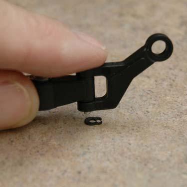
100 C) Head Axle Components - Bag #8C # M5 Blade Bolt #0331 M13 x.5 S/S Shim # Retaining Clip # M3 x 20 Dowel Pin #0057 M4 x 4 Socket Set Screw # M5 Flanged Bolt #0324 M10 x 16 x 1 Shim #0023 M5 Locknut # One Piece Dampers # S/S Shim # Clip Application Tool #0319 M8 x 10.5 Ball Bearing 4 each #120-5 Axle # Thrust Bearing #120-7 M5 x 15 Washer Page 100 of 138 Copyright Miniature Aircraft USA Created: 11/14/2006


101 8C.1 - Blade Arm Assembly Parts Relationship #120-5 # # #0324 #120-7 #0331 #0319 #0319 # # # # #0023 8C.1 Assemble Blade Arms 8C.1.a 8C.1.b 8C.1.c # #0319 #0319 Created: 11/14/2006 Copyright Miniature Aircraft USA Page 101 of 138


102 8C.1.d 8C.1.e 8C.1.f Locate Small Diameter Race Locate Large Diameter Race 8C.1.g 8C.1.h 8C.1.i # Small Diameter # Large Diameter Rounded Edge Seat In Groove # Middle Bearing # # # C.1.j 8C.1.k 8C.1.l #0324 # #0331 # Page 102 of 138 Copyright Miniature Aircraft USA Created: 11/14/2006


103 8C.2 Install Blade Arms 8C.2.a 8C.2.b #120-7 # C.2.c Created: 11/14/2006 Copyright Miniature Aircraft USA Page 103 of 138

 #0555-1 #0049-3 (3) #0555-1 #0063 #126-87 #126-88 #0053-5 #126-88 #126-87 #0063 #0133 Page 104 of 138 Copyright Miniature Aircraft USA")
104 D) Flybar - Bag #8D #0337 M2 x 30 Control Rod #0133 Ball Link - Long 8 each # M2 x 8 Socket Bolt 6 each #0135 Ball Link Short 4 each # Flybar Control Arm # M3 Ball #0063 M3 x 10 Socket Bolt 4 each # Flybar Paddle #0335 M2 x 75 Control Rod # Flybar Control Spacer 4 each #0313 M2 x 15 Control Rod # M3 x 16 Socket Set Screw #0052 M3 x 6 Socket Set Screw 4 each Parts Relationship #0133 #0052 (2) #0063 # # # #0052 (2) #0063 # (3) # # (3) # #0063 # # # # # #0063 #0133 Page 104 of 138 Copyright Miniature Aircraft USA Created: 11/14/2006
")
 F Completed Control")


105 8D.1 Assemble/Install Flybar Control System Rod Lengths #0133 (2) Swashplate/Bell 61 mm L #0337 Flybar Control #0133 (2) F Completed Control Rods Prints Actual Size 9mm #0135 #0313 Flybar/Bell M 8D.1.a 8D.1.b 8D.1.c # # F 10mm # # Created: 11/14/2006 Copyright Miniature Aircraft USA Page 105 of 138


106 8D.1.d 8D.1.e 8D.1.f Bevel Towards Inside #0063 # # # D.1.g 8D.2 Assemble/Install Flybar Bell Links 8D.2.a 8D.2.b Building Notes snap one end of the assembled link onto the double ball on the bell mixer and the other onto the double ball on the flybar carrier. Repeat for the other side The flybar needed for the next step is located in a separate bag. M Page 106 of 138 Copyright Miniature Aircraft USA Created: 11/14/2006
 8D.")


107 8D.3 Install Flybar 8D.3.a 8D.3.b 156 mm #0052 (2) 8D.4 Install Flybar Paddles 8D.4.a 8D.4.b 8D.4.c 30 mm # D.4.d Building Notes make sure both flybar paddles are parallel to each other and the flybar control arms Created: 11/14/2006 Copyright Miniature Aircraft USA Page 107 of 138


108 8D.5 Install Rotor Head 8D.5.a 8D.5.b 8D.5.c Main shaft hole # D.5.d 8D.5.e 8D.5.f F #0057 8D.5.g 8D.5.h L Page 108 of 138 Copyright Miniature Aircraft USA Created: 11/14/2006

109 Step #9 Tail Rotor Assembly A) Tail Rotor Hub - Bag #9A # Tail Rotor Hub # T/R Blade Grips # M5 x 10 Ball Bearings #0097 M3 x 22 Phillips Bolt # M4 x.003 S/S Shim #0457 Thrust Bearings #0019 M3 Locknut #0021 M4 Locknut Created: 11/14/2006 Copyright Miniature Aircraft USA Page 109 of 138

110 9A.1 Assemble Tail Rotor Hub Parts Relationship Small Inside Diameter # Small Inside Diameter # #0457 # # #0457 # #0021 #0021 #0097 Large Inside Diameter Large Inside Diameter #0097 #0019 #0019 # # Page 110 of 138 Copyright Miniature Aircraft USA Created: 11/14/2006


111 9A.1.a 9A.1.b 9A.1.c # # Locate Large Diameter Race #0457 Bearing Locate Small Diameter Race 9A.1.d 9A.1.e 9A.1.f #0457 Large Diameter Race #0457 Small Diameter Race # # A.1.g 9A.1.h 9A.1.i #0021 Tighten until snug, then Loosen only until blade holder can be moved with no friction or binding. Created: 11/14/2006 Copyright Miniature Aircraft USA Page 111 of 138

 #0019 (2)")

112 9A.2 Install Tail Rotor Blades 9A.2.a 9A.2.b #0097 (2) #0019 (2) 9A.2.c Page 112 of 138 Copyright Miniature Aircraft USA Created: 11/14/2006

113 B) Tail Rotor Pitch Yoke - Bag #9B # Pitch Yoke 1 Each #0443 M6 Retaining Clip 2 Each #0439 M6 x 10 Ball Bearing 2 Each # Pitch Links 2 Each #0015 M2 Hex Nut 2 Each #0101 M2 x 5 Threaded Ball 2 Each #0435 Brass Slider 1 Each #0437 Pitch Control Ring 1 Each #0049 M2 x 10 Socket Bolt 2 Each Created: 11/14/2006 Copyright Miniature Aircraft USA Page 113 of 138
 #0049 (2) Page 114 of 138 Copyright Miniature Aircraft USA Created: 11/14/2006")
114 9B.1 Assemble TR Pitch Yoke Parts Relationship #0439 #0101 #0435 #0437 #0439 #0443 (2) # #0015 #0015 # # #0049 (2) #0049 (2) Page 114 of 138 Copyright Miniature Aircraft USA Created: 11/14/2006
")


115 9B.1.a 9B.1.b 9B.1.c #0439 (2) #0435 #0437 #0101 9B.1.d 9B.1.e 9B.1.f #0443 9B.1.g # The yoke must remain free with no bearing binding. The clip only needs to snug to remove play 9B.1.h If the parts don t rotate freely, use a razor knife to loosen the clip slightly #0443 #0015 #0049 Created: 11/14/2006 Copyright Miniature Aircraft USA Page 115 of 138

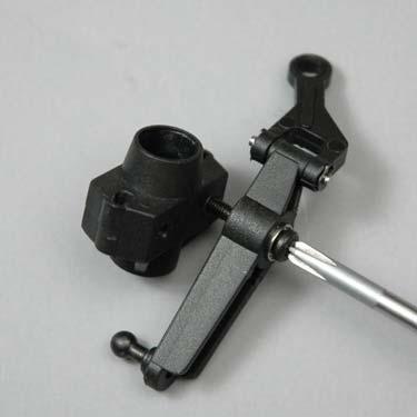
116 C) Tail Rotor Transmission - Bag #9C #0445 Bellcrank 1 Each # M3 Brass Spacer 1 Each #0159 M3 x 7 Ball Bearing 2 Each # Assembled Gear Box 1 Each # M3 Locknut Thin 1 Each #0049 M2 x 10 Socket Bolt 2 Each #0015 M2 Hex Nut 1 Each #0097 M3 x 22 Phillips Bolt 1 Each #0103 M3 x 5 Threaded Ball 1 Each #0056 M3 x 5 Dog-Point Set Screw 2 Each Page 116 of 138 Copyright Miniature Aircraft USA Created: 11/14/2006

117 9C.1 Assemble T/R BellCrank Parts Relationship # #0445 #0015 # # #0097 #0159 #0159 #0103 Created: 11/14/2006 Copyright Miniature Aircraft USA Page 117 of 138


118 9C.1.a 9C.1.b 9C.1.c #0445 #0159 #0103 # C.1.d #0015 #0159 9C.2 Install T/R BellCrank 9C.2.a 9C.2.b #0097 # Page 118 of 138 Copyright Miniature Aircraft USA Created: 11/14/2006


119 9C.3 Install T/R Pitch Yoke 9C.3.a 9C.3.b 9C.3.c #0056 (2) Created: 11/14/2006 Copyright Miniature Aircraft USA Page 119 of 138

120 Step #10 Locate Tail Boom Components A) Tail Boom Components - Bag #10 # Aluminum Tail Boom 1 Each # Torque Tube T/R Drive 1 Each # Tail Boom Supports 25 1 Each # T/R Pushrod Graphite 1 Each # Flybar 18-5/8 1 Each Building Notes Locate Bag 10. These parts are to be used in other steps. They are bagged together due to their size and to ensure that they are not damaged. Page 120 of 138 Copyright Miniature Aircraft USA Created: 11/14/2006

121 Step #11 Tail Boom Assembly A) Tail Boom Mounts - Bag #11A # Horizontal Fin 1 Each # Rear Canopy Mount 2 Each # Vertical Fin 1 Each #0186 Front Boom Mount Set 1 Each #123-86A Gear Box and Fin Mount 1 Each # Horizontal Fin Mount 1 Each #123-86B Gear Box Mount 1 Each #0077 M3 x 30 Socket Bolts 4 Each #0006 M3 Star Lock washer 2 Each #0063 M3 x 10 Socket Bolts 8 Each #0019 M3 Locknut 3 Each #0065 M3 x 12 Socket Bolt 1 Each #0061 M3 x 8 Socket Bolts 2 Each #0109 M3 x 8 Threaded Ball 2 Each #0017 M3 Hex Nut 8 Each #0009 M3 Washer 8 Each #0032 M2.9 x 9.5 Phillips Screw 2 Each #0027 M2.2 x 9.5 Phillips Screw 2 Each Created: 11/14/2006 Copyright Miniature Aircraft USA Page 121 of 138

.")

122 1A.1 Install Tube Drive 11A.1.a # Building Notes before inserting the tube drive into the tail boom as shown, spray inside the boom with a spray glass cleaner (like Windex ). This will make the tube drive easier to insert # A.2 Install T/R Transmission 11A.2.a 11A.2.b Align Holes Page 122 of 138 Copyright Miniature Aircraft USA Created: 11/14/2006
 #0063 (2) #0589-4 #123-86B #0017 (4) #0006 #0009 #0061 Created: 11/14/2006 Copyright Miniature Aircraft USA Page 123 of")
123 11A.3 Install Vertical Fin Mount/Fin Parts Relationship #0061 #0009 #0063 (2) #0006 #0032 (2) #0017 (2) #123-86A #0063 (2) #0063 (2) #0017 (2) #0063 (2) # #123-86B #0017 (4) #0006 #0009 #0061 Created: 11/14/2006 Copyright Miniature Aircraft USA Page 123 of 138


 h #0032")


124 11A.3.a 11A.3.b 11A.3.c #123-86B #0017 (2) #0006 #0009 #0009 #123-86A #0006 #0017 (6) # A.3.d 11A.3.e 11A.3.f #0061 #0063 # A.3.g #0063 (4) 11A.3.h #0032 Building Notes do not overtighten any bolts in this assembly # Page 124 of 138 Copyright Miniature Aircraft USA Created: 11/14/2006
 #0065 Created: 11/14/2006 Copyright Miniature Aircraft USA Page 125")
125 11A.4 Install Horizontal Fin Mount/Fin Parts Relationship # #0019 # #0009 #0027 (2) #0065 Created: 11/14/2006 Copyright Miniature Aircraft USA Page 125 of 138


126 11A.4.a # mm 11A.4.b 11A.4.c #0009 #0019 #0027 #0065 Front 11A.4.d # Page 126 of 138 Copyright Miniature Aircraft USA Created: 11/14/2006


127 11A.5 Install Tail Rotor 11A.5.a 11A.5.b 11A.5.c Created: 11/14/2006 Copyright Miniature Aircraft USA Page 127 of 138


128 11A.6 Install Front Tail Boom Mount Parts Relationship # #0109 #0009 #0186 #0077 #0077 #0019 #0009 #0077 #0109 # #0009 Forward # A.6.a 11A.6.b 11A.6.c #0109 #0009 #0077 #0077 #0009 #0009 # # #0019 Page 128 of 138 Copyright Miniature Aircraft USA Created: 11/14/2006


129 B) Tail Rotor Pushrod Components - Bag #11B # Brass Sleeve 1 Each #0043 M2 x 10 Slotted Bolt 1 Each #0039 M2.5 x 12 Phillips Bolt 1 Each # Pushrod Guide 1 Each #0015 M2 Hex Nut 1 Each #0020 M2.5 Hex Nut 1 Each #0477 Guide Support 1 Each #121-5 M3 x 75 Control Rod 1 Each #121-6 M3 x 42 Control Rod 1 Each # Teflon Heat Shrink Tube 1 Each #133-1 Ball Link - Grey 1 Each Parts Relationship #0020 # #0477 #0015 #0043 #0039 Created: 11/14/2006 Copyright Miniature Aircraft USA Page 129 of 138


130 11B.1 Assemble/Install T/R Pushrod Guide 11B.1.a 11B.1.b #0020 #0043 #0039 Forward #0477 #0015 # /2 from front of tail boom To front of guide 11B.2 Install Tailboom 11B.1.a 11B.1.b 11B.1.c 90 Page 130 of 138 Copyright Miniature Aircraft USA Created: 11/14/2006


131 11B.3 Assemble T/R Pushrod 11B.3.a 11B.3.b 11B.3.c #133-1 # # # #133-1 #121-5 #121-6 T/R Pushrod - Front T/R Pushrod - Rear 11B.3.d 11B.3.e 11B.3.f 14 from back of pushrod To center of sleeve # Forward 11B.3.g 11B.3.h 11B.3.i Masking Tape Heat Gun # # mm #121-5 Created: 11/14/2006 Copyright Miniature Aircraft USA Page 131 of 138


132 11B.3.j Building Notes test assemble all of these components before applying adhesive Remove Tape 11B.4 Install T/R Pushrod 11B.4.a 11B.4.b 11B.4.c Page 132 of 138 Copyright Miniature Aircraft USA Created: 11/14/2006


 #3293-1 #0003 #0872-8 #0019 Created: 11/14/2006 Copyright Miniature Aircraft USA")
133 C) Tail Boom Support Components - Bag #11C #0079 M3 x 35 Socket Bolts 2 Each # Support End M3 Hole # Support End M4 Hole # Round Spacer 2 Each 2 Each 2 Each #0004 M4 Washer 2 Each #0081 M4 x 16 Socket Bolts 2 Each #0048 M3.5 x 25 Socket Set Screws 4 Each #0003 M3 Washer 2 Each #0019 M3 Locknut 2 Each 11C.1 Assemble Tail Boom Supports Parts Relationship # #0079 #0003 # #0048 (4) # #0003 # #0019 Created: 11/14/2006 Copyright Miniature Aircraft USA Page 133 of 138


 #0003 (2)")


134 Parts Relationship 11C.1.a 11C.1.b # (2) #0048 #0081 #0004 # (2) # (2) 11C.2 Install Tail Boom Supports 11C.2.a 11C.2.b 11C.2.b # # Wide End #0079 (2) #0003 (2) # #0019 (2) 11C.2.d Install Bolt This Way 11C.2.e # # #0081 Page 134 of 138 Copyright Miniature Aircraft USA Created: 11/14/2006


135 11C.3 Install Rotor Blades 11C.3.a 11C.3.b # Building Notes Tighten each blade equally. The blade should be tight enough to be hard to move in the blade holder. # C.4 Install Canopy 11C.4.a 11C.4.b 11C.4.c Created: 11/14/2006 Copyright Miniature Aircraft USA Page 135 of 138

136 Page 136 of 138 Copyright Miniature Aircraft USA Created: 11/14/2006

137 Created: 11/14/2006 Copyright Miniature Aircraft USA Page 137 of 138

138 Page 138 of 138 Copyright Miniature Aircraft USA Created: 11/14/2006
Assembly instructions
 Assembly instructions Step up to Excellence with X-cell 2 Table of Contents Kit Introduction...4 R/C Helicopter Safety...4 Warning...4 General Guidelines...4 Academy of Model Aeronautics (AMA)...5 Kit
Assembly instructions
 Assembly instructions Step up to Excellence with X-cell 2 Table of Contents Kit Introduction...4 R/C Helicopter Safety...4 Warning...4 General Guidelines...4 Academy of Model Aeronautics (AMA)...5 Kit
Specifications ASSEMBLY INSTRUCTIONS
 ASSEMBLY INSTRUCTIONS Specifications Length : 6 mm Height : 218 mm Main Blade : 325 mm Main Rotor Diameter : 723 mm Tail Rotor Diameter : 150 mm Motor Pinion Gear : 16T (14T) Main Drive Gear : 150T Main
Hawk Sport. Quick Build Guide. Century Helicopter Products. Designed and Developed in USA
 Hawk Sport Quick Build Guide This Century HAWK SPORT kit comes in a QUICK BUILD format that has most of the major systems already assembled into sub-assemblies. These are packed seperately into their specific
AVANT Aurora Ultimate 90
 2 AVANT Aurora Ultimate 90 Assembly Manual AVANT Aurora Ultimate 90 Assembly Manual V2.00 LIABILITY DISCLAIMER This kit is for a radio controlled (RC) helicopter. RC Helicopters are not toys. Moving parts
8-3 MAIN ROTOR BLADE ATTACHMENT (BLADES NOT INCLUDED)
") 8-3 MAIN ROTOR BLADE ATTACHMENT (BLADES NOT INCLUDED) Two sets required Socket Head Bolt, 4 x 35 mm...2 pcs Hold the 4 mm Lock Nut while tightening using a Wiha 7 mm Nut Driver or equivalent. Lock Nut,
8-3 MAIN ROTOR BLADE ATTACHMENT (BLADES NOT INCLUDED) Two sets required Socket Head Bolt, 4 x 35 mm...2 pcs Hold the 4 mm Lock Nut while tightening using a Wiha 7 mm Nut Driver or equivalent. Lock Nut,
AVANT Aurora Ultimate 90
 2 AVANT Aurora Ultimate 90 Assembly Manual AVANT Aurora Ultimate 90 Assembly Manual V1.08 LIABILITY DISCLAIMER This kit is for a radio controlled (RC) helicopter. RC Helicopters are not toys. Moving parts
J & D Machine / Hyperdrive / MSA 3711 Moon Bend Rd. Chapel Hill, TN 37034
 J & D Machine / Hyperdrive / MSA 3711 Moon Bend Rd. Chapel Hill, TN 37034 www.hyperdriveracing.com 1 You now own a state of the art 1/10 scale oval race car. The Hyperdrive Assault has gone through months
Conversion Guide. HB7-RCT7 For T-Rex 600 Author: Carey Shurley. Version 1.0 Last Revised: 02/15/2011
 Conversion Guide HB7-RCT7 For T-Rex 600 Author: Carey Shurley Version 1.0 Last Revised: 02/15/2011 Page 1 of 30 Copyright HeliBug Inc. Created: 02/15/2011 For More Information contact: HeliBug Inc. 8901
Shown with optional GFR-1017R Body Posts. J & D Machine / Hyperdrive / MSA 3711 Moon Bend Rd. Chapel Hill, TN
 Shown with optional GFR-1017R Body Posts J & D Machine / Hyperdrive / MSA 3711 Moon Bend Rd. Chapel Hill, TN 37034 www.hyperdriveracing.com 1 You now own a state of the art 1/10 scale oval race car. The
Issue/Rev. 0.3 (2/04) Bulletin P
 Bulletin P") Form No. P0906.03 E-Type Transmitter Parts List Issue/Rev. 0.3 (2/04) Bulletin P0906.03 (Previous Design) Switch and Network Assembly The Switch and Network Assembly is no longer available. To replace
Form No. P0906.03 E-Type Transmitter Parts List Issue/Rev. 0.3 (2/04) Bulletin P0906.03 (Previous Design) Switch and Network Assembly The Switch and Network Assembly is no longer available. To replace
RADIO CONTROL MODEL ASSEMBLY INSTRUCTIONS. Wasp
 RADIO CONTROL MODEL ASSEMBLY INSTRUCTIONS Wasp TRAINER Almost ready-to-fly Wingspan 1520mm Fuselage length 1105mm Engine: 40-46 2T / 52-60 4T Electric Motor: 600-700W Radio: 5 channel / 4-5 servo RC Functions:
SELECT 3-BURNER PROPANE BARBECUE Assembly Manual
 SELECT 3-BURNER PROPANE BARBECUE Assembly Manual 85-3096-2 (G31221) Propane 1 Year limited Warranty Read and save manual for future reference. Assemble your grill immediately. Missing or damaged parts
Installation, Maintenance & Parts Manual
 Installation, Maintenance & Parts Manual 00 Series Center Drive Conveyors Table of Contents Warnings General Safety........................... Introduction....................................... Product
Installation, Maintenance & Parts Manual
 Installation, Maintenance & Parts Manual 2100 Series Center Drive Conveyors Table of Contents Warnings General Safety........................... 2 Introduction....................................... 2
Bag 1. Bag 1. Center Pivot. Center Pivot
 8 00734 01901 5 Center Pivot Bag 1 3374 - Center Pivot Socket 4019 - Alum Pivot ball 3254-2-56 Button Head *Note - Sometimes it is helpful to slightly over-tighten the top clamp screws, then work the ball
Manual GLOGO
 Manual GLOGO 690 www.mikado-heli.de Mikado Model Helicopters GmbH Graf-von-Schwerin-Str. 40 14469 Potsdam Germany phone +49 (0)331 3749-0 fax +49 (0)331 3749-11 www.mikado-heli.de Mikado Model Helicopters
MARACANA ASSEMBLY INSTRUCTION .40 ARF LOW WING TRAINER RADIO CONTROL MODEL. Every body can fly
 RADIO CONTROL MODEL ASSEMBLY INSTRUCTION MARACANA.40 ARF LOW WING TRAINER Every body can fly VQA085 EP GP You can use both Gas or Electric power Wingspan: 59in.(1520mm) Fuselage length: 48in.(1220mm) Engine:
Heavy Duty Actuators CONTROLS. Pneumatic Actuators for Quarter-Turn Valves and Dampers Torques to 1,600,000 in. lbs. Double Acting and Spring Return
 CONTROLS Division of A-T Controls Heavy Duty Actuators Pneumatic Actuators for Quarter-Turn Valves and Dampers Torques to,600,000 in. lbs. Double Acting and Spring Return THD S E R I E S The Triac line
RECOMMENDED MOTOR AND BATTERY SET UP
 SPECIFICATION - Wingspan: 1404mm (55.3in) - Length: 1134mm (44. 6 in) - Flying weight: 3.2-3.4 kg - Covering type: Genuine ORACOVER - Spinner size: scale type (not included) - Radio: 4 channel minimum
SIZE.120 OR 30CC SCALE 1:5 ARF
 PC21 PILATUS MK2 SIZE.120 OR 30CC SCALE 1:5 ARF SPECIFICATION - Wingspan: 1772mm (69.72in) - Length: 2019mm (79.5 in) - Flying weight: 6.4-7.2 kg - Wing area: 57.6 dm2 - Wing loading: 113g/dm2 - Wing type:
2200 Series Center Drive Conveyors
 2200 Series Center Drive Conveyors Installation, Maintenance & Parts Manual DORNER MFG. CORP. INSIDE THE USA OUTSIDE THE USA P.O. Box 20 975 Cottonwood Ave. TEL: 1-800-397-8664 TEL: 262-367-7600 Hartland,
AVIATOR 25 ARF Almost Ready-to-Fly
 AVIATOR 25 ARF Almost Ready-to-Fly Instruction Manual Specifications Wingspan: 54.3 in (1380mm) Length: 45.2 in (1150mm) Wing Area: 438 sq in (34sq dm) Flying Weight: 3.8 b (1700g) Dear Customer, Congratulations
51in Aerobatic Series Sukhoi SU-26M Almost-Ready-to-Fly. Instruction Manual. Specifications
 51in Aerobatic Series Sukhoi SU-26M Almost-Ready-to-Fly Instruction Manual Specifications Wingspan: 51.2 in (1300mm) Length: 51.2 in (1300mm) Wing Area: 581 sq in (37.5sq dm) Flying Weight: 3.5 lb (1600g)
Radio control model INSTRUCTION MANUAL PYLON RACING. Wingspan: 1148mm (45.2 ) Radio : 4 channels Engine : two-stroke
 Radio : 4 channels Engine : two-stroke") VQA038 VQA039 Radio control model INSTRUCTION MANUAL MAGIC PYLON RACING Wingspan: 1148mm (45.2 ) Radio : 4 channels Engine :.25 -.32 two-stroke WARNING! This radio control model is not a toy. If modified
VQA038 VQA039 Radio control model INSTRUCTION MANUAL MAGIC PYLON RACING Wingspan: 1148mm (45.2 ) Radio : 4 channels Engine :.25 -.32 two-stroke WARNING! This radio control model is not a toy. If modified
Aviator Pro 120 ARF. Instruction Manual. Specifications
 Aviator Pro 120 ARF Instruction Manual Specifications Wingspan: 110 in (2800 mm) Length: 74 in (1870 mm) Wing Area: 1581sq in (102 sq dm) Weight: 11.4-13.4 lbs (5190-6100 g) Dear Customer, Congratulations
Manual LOGO 550 SE.
 Manual LOGO 550 SE www.mikado-heli.de Mikado Model Helicopters GmbH Friedrich-Klausing-Straße 14469 Potsdam Germany phone +49 (0)331 3749-0 fax +49 (0)331 3749-11 www.mikado-heli.de Mikado Model Helicopters
I n s t r u c t i o n M a n u a l. Instruction Manual SPECIFICATION
 I n s t r u c t i o n M a n u a l Instruction Manual SPECIFICATION - Wingspan: 3200mm (125,9 in) - Length: 1650mm (64,9 in) - Flying weight: 3000gr 3200gr - Wing area: 64.5 dm2 - Wing loading: 46g/dm2
SKYARTEC MOSQUITO 3D PRO
 SKYARTEC MOSQUITO 3D PRO Instruction & assembly manual Specifications: This micro R/C helicopter has the most advanced capabilities. 120 degree CCPM control, collective main and tail rotors, belt tail
Instruction Manual book
 book ITEM CODE:BH 115. SPECIFICATION Wingspan : 6,000 mm 236,22 in. Length : 2,740 mm 107,87 in. Weight : 17.5kg 38.5Lbs. Radio : 08 channels. Servo : 07-08 HS-5685MH(HITEC) Battery : 2 Cells-Li-Po 7.4V
Assembly Manual. 1/10th Formula 1 Car
 Assembly Manual 1/10th Formula 1 Car Center Pivot Bag 1 3374 - Center Pivot Socket 40194 - Hard Anodized Alum Pivot ball 3254-2-56 *Note - Sometimes it is helpful to slightly over-tighten the top clamp
RADIO CONTROL MODEL HURRICANE
 RADIO CONTROL MODEL VQAA040G VQAA040B HURRINE Almost ready to fly SPECIFITIONS Wingspan...63 in. / 161cm Length...50 in. / 129cm Engine...50~60 2T / 70~90 4T Or Electric equivalent. RC Functions: Motor
96in Super Decathlon ARF
 96in Super Decathlon ARF Instruction Manual Specifications Wingspan: 96in (2438mm) Length: 63.5 in (1614mm) Weight: Approx. 13lbs (6.5kg) 1 Dear Customer, Congratulations on your purchase of Super Decathlon
TABLE OF CONTENTS INTRODUCTION 3 CUSTOMER SERVICE 4 FEATURES 5 FRE-ASSEMBLY INFORMATION 6 REQUIRED TOOLS 7 HARDWARE & OPTIONAL ACCESSORIES 8
 Page 1 of 84 TABLE OF CONTENTS INTRODUCTION 3 CUSTOMER SERVICE 4 FEATURES 5 FRE-ASSEMBLY INFORMATION 6 REQUIRED TOOLS 7 HARDWARE & OPTIONAL ACCESSORIES 8 OTHER HARDWARE & OPTIONAL ACCESSORIES 9 OTHER REQUIREMENTS
Instruction Manual BULLDOG. Wingspan : 1410 mm (55.5in) : 1450 mm (57.1in) : 4900gr gr. Weight. : 6-9 Channel/ 7 servo high torque, 1standard
 : 1450 mm (57.1in) : 4900gr gr. Weight. : 6-9 Channel/ 7 servo high torque, 1standard") Wingspan : 1410 mm (55.5in) Length Weight Radio Engine : 1450 mm (57.1in) : 4900gr - 5600gr : 6-9 Channel/ 7 servo high torque, 1standard : 1.20/ 2 stroke 1.80/ 4 stroke KIT CONTENTS: We have organized
Wingspan : 1410 mm (55.5in) Length Weight Radio Engine : 1450 mm (57.1in) : 4900gr - 5600gr : 6-9 Channel/ 7 servo high torque, 1standard : 1.20/ 2 stroke 1.80/ 4 stroke KIT CONTENTS: We have organized
PRIME 3-BURNER PROPANE BARBECUE Assembly Manual
 PRIME 3-BURNER PROPANE BARBECUE Assembly Manual 85-3135-0 / G32010 1 Year limited Warranty Read and save manual for future reference. Assemble your grill immediately. Missing or damaged parts claims must
Instruction Manual. Specification:
 Instruction Manual L O W Specification: Wingspan: 133 cm (52.3 inches) Length : 104 cm (40.9 inches) Weight : 1790gr Engine : 25-32 two stroke Radio : 4 channel - 4 servo W I N G KIT CONTENTS: We have
PRIME 3-BURNER PROPANE BARBECUE Assembly Manual
 PRIME -BURNER PROPANE RBECUE Assembly Manual 85-15-0 / G2012 1 YEAR LIMITED WARRANTY READ AND SAVE MANUAL FOR FUTURE REFERENCE. Assemble your grill immediately. Missing or damaged parts claims must be
ALMOST READY TO FLY. Wing Span in cm. 2
 ASSEMBLY MANUAL ALMOST READY TO FLY MS:X9 Specifications Wing Span --------------------------61.4 in ---------------------------156cm. 2 Wing Area --------------------------606.1 sq.in ------------------
48in Sbach-342. Instruction Manual. Specifications
 48in Sbach-342 Instruction Manual Specifications Wingspan: 48in (1219mm) Length: 46in (1163mm) Wing Area: 471sq in (30.4sq dm) Flying Weight: 1.8-2.0lb (800-900g) Dear Customer, www.valuehobby.com/48in-s342-arf.html
Assembly Manual. 1/10th World GT car
 Assembly Manual 1/10th World GT car Center Pivot Bag 1 3374 - Center Pivot Socket 40194 - Hard Anodized Alum Pivot ball 3254-2-56 Button Head *Note - Sometimes it is helpful to slightly over-tighten the
Set-up, Operation & Maintenance Manual
 Set-up, Operation & Maintenance Manual 2100 Series Center Drive Conveyors Table of Contents Warnings General Safety.................... 2 Introduction................................ 2 Product Description..........................
RECOMMENDED MOTOR AND BATTERY SET UP
 SPECIFICATION - Wingspan: 6000mm (236.2 in) - Length: 2873mm (113.1 in) - Flying weight: 14-18 kg - Wing area: 219.4 dm2 - Wing loading: 64g/dm2 - Wing type: HQ airfoils - Covering type: Genuine ORACOVER
REV: 000. Super Seca Flash Cure Units
 REV: 000 Super Seca Flash Cure Units Table Of Contents Introduction 2 Standard Operating Guide 2 Features & Specs 2 External Layout 4-15 Internal Layout 16-24 Plug Guide 25 Wiring Diagrams 26-28 F.A.Q.
SAFARI Helicopter Flight Control Rigging Manual Revision 9 4/3/2010 CHR International Inc.
 SAFARI Helicopter Flight Control Rigging Manual Revision 9 4/3/2010 CHR International Inc. The following procedures are meant as a guide to assist you in the safe configuration of your helicopter s Flight
STICK F Class 60 Class INSTRUCTION MANUAL. Or Electric equivalent. (2T engine) (4T engine) Radio control model SPECIFICATIONS
 (4T engine) Radio control model SPECIFICATIONS") Radio control model 45 Class 60 Class (2T engine) (4T engine) Or Electric equivalent INSTRUCTION MANUAL STICK F - 1500 SPECIFICATIONS Wingspan 60 in. Length 38.5 in. Electric Motor 650 Watt Glow Engine.45
Radio control model 45 Class 60 Class (2T engine) (4T engine) Or Electric equivalent INSTRUCTION MANUAL STICK F - 1500 SPECIFICATIONS Wingspan 60 in. Length 38.5 in. Electric Motor 650 Watt Glow Engine.45
8mm EPP Acrocub. Instruction Manual. Specifications
 8mm EPP Acrocub Instruction Manual Specifications Wingspan: 34.6 in (880mm) Length: 31.5 in (800mm) Wing Area: 213.9 sq in (13.8sq dm) Flying Weight: Approx. 9oz (270g) Dear Customer, www.valuehobby.com/8mm-epp-acrocub.html
Manual LOGO 600 SE.
 Manual LOGO 600 SE www.mikado-heli.de Mikado Model Helicopters GmbH Friedrich-Klausing-Straße 4469 Potsdam Germany phone +49 (0) 749-0 fax +49 (0) 749- www.mikado-heli.de Mikado Model Helicopters GmbH
EXTRA 330LX. Specifications: Code: SEA274. Graphics and specifications may change without notice. ASSEMBLY MANUAL
 ASSEMBLY MANUAL EXTRA 330LX Code: SEA274 Graphics and specifications may change without notice. Specifications: Wingspan---------------82.0 in (208.2 cm). Wing area---------------1349.4 sq.in ( 87.1 sq.dm).
Instruction Manual book
 Instruction Manual book ITEM CODE:BH118. SPECIFICATION Wingspan : 1,050 mm 41.34 inches. Length : 950mm 37.4 inches. Weight : 1 kg 2.2 lbs. Radio : 04 channels. Servo : 4 mini servos. Motor : BL2215/20
YAK-55M 1.8. Forget the rest - a YAK ist the best! Assembly instructions. Gernot
 YAK-55M 1.8 Assembly instructions Forget the rest - a YAK ist the best! Gernot Table of contents 1.Specifications (metric units)...2 2.Recommended Setups...2 3.Required tools and adhesives:...2 4.Warning...3
SELECT 4-BURNER PROPANE BARBECUE Assembly Manual
 SELECT 4-BURNER PROPANE RBECUE Assembly Manual 85-3064-8 (G43257) Propane 1 Year limited Warranty Read and save manual for future reference. Assemble your grill immediately. Missing or damaged parts claims
Contents. Introduction. Warning. Cautions. Transmitter Features. Receiver Identification. Switch Between Left-Hand and Right-Hand Throttles
 RX-408 Contents Introduction Warning Cautions Transmitter Features Receiver Identification Switch Between Left-Hand and Right-Hand Throttles Flybar Set Assembly Battery Mounting and Adjustment Swashplate
Instruction Manual. Wingspan : 2270mm (89.37 inches) : 1870mm (73.62 inches) : 7400gr gr. : 4 channel - 6 standard servo.
 : 1870mm (73.62 inches) : 7400gr gr. : 4 channel - 6 standard servo.") Wingspan : 2270mm (89.37 inches) g Length : 1870mm (73.62 inches) Weight : 7400gr - 7600gr Radio : 4 channel - 6 standard servo Engine : 25cc-35cc KIT CONTENTS: We have organized the parts as they come
Wingspan : 2270mm (89.37 inches) g Length : 1870mm (73.62 inches) Weight : 7400gr - 7600gr Radio : 4 channel - 6 standard servo Engine : 25cc-35cc KIT CONTENTS: We have organized the parts as they come
TM ETRS-TM35FIN-ETRS89 WTG
 Noise calculation model: ISO 9613-2 General Wind speed: 8,0 m/s Ground attenuation: General, Ground factor: 0,4 Meteorological coefficient, C0: 0,0 db Type of demand in calculation: 1: WTG noise is compared
3DX 450 ASE V3 COPYRIGHT. CONTENTS 2 Safety Note s 3...Hardware Identification 4...Assembly Instructions 5...Maintenance Main Rotor Assembly
 3DX 450 ASE V3 COPYRIGHT Instruction Manual Author: Per Backman Date: 10/30/2006 CONTENTS 2 Safety Note s 3...Hardware Identification 4...Assembly Instructions 5...Maintenance 6-8...Main Rotor Assembly
Instruction Manual book
 Instruction Manual book ITEM CODE:BH118. SPECIFICATION Wingspan : 1,050 mm 41.34 inches. Length : 950mm 37.4 inches. Weight : 1 kg 2.2 lbs. Radio : 04 channels. Servo : 4 mini servos. Motor : KMS 2814/05
RECOMMENDED MOTOR AND BATTERY SET UP
 SPECIFICATION - Wingspan: 2190mm (86.2 in) - Length: 1907mm (75 in) - Flying weight: 9000-12000 gr - Wing area: 92 dm2 - Wing loading: 98g/dm2 - Wing type: Naca airfoils - Retract gear type: Air-retract
Twister 3D Storm The Ultimate 3D Electric Helicopter
 The Ultimate 3D Electric Helicopter SPECIFICATIONS Main rotor diameter 720mm Tail rotor diameter..135mm Length..630mm Weight (without receiver & battery)....500g (17.5oz) CONTENTS 1...Assembled helicopter
SBACH SCALE 1:4 ½ ARF
 SPECIFICATION - Wingspan: 1663mm (65.5 in) - Length: 1638mm (64.5 in) - Flying weight: 4700-5200 gr - Wing area: 56 dm2 - Wing loading: 85g/dm2 - Wing type: Naca airfoils - Covering type: Genuine ORACOVER
Calandra Racing Concepts
 Calandra Racing Concepts Carpet Knifeä Version 3 Assembly and Setup Manual Congratulations! You now own the best 1/12th scale car on the market today, the Carpet Knifeä Version 3. This completely new car
Instruction Manual. Wingspan : 1400 mm (55.12 inch) : 1480 mm (58.27 inch) : 5500gr gr. : 6-9 channel/ 8 servo high torque,1 standard
 : 1480 mm (58.27 inch) : 5500gr gr. : 6-9 channel/ 8 servo high torque,1 standard") Wingspan : 1400 mm (55.12 inch) g Length : 1480 mm (58.27 inch) Weight : 5500gr - 6000gr Radio : 6-9 channel/ 8 servo high torque,1 standard Engine : GT 22 OS KIT CONTENTS: We have organized the parts
Wingspan : 1400 mm (55.12 inch) g Length : 1480 mm (58.27 inch) Weight : 5500gr - 6000gr Radio : 6-9 channel/ 8 servo high torque,1 standard Engine : GT 22 OS KIT CONTENTS: We have organized the parts
RECOMMENDED MOTOR AND BATTERY SET UP
 SPECIFICATION - Wingspan: 1800mm (70.8 in) - Length: 1355mm (53.3 in) - Flying weight: 4100-4300 g - Wing area: 51 dm2 - Wing loading: 80g/dm2 - Wing type: Naca airfoils - Covering type: Genuine ORACOVER
I/C FLIGHT GUIDELINES
 SPECIFICATION - Wingspan: 3500mm (137.8 in) - Length: 1650mm (64.96 in) - Flying weight: 3700-4000 gr - Wing area: 75 dm2 - Wing loading: 49g/dm2 - Wing type: HQ profile - Covering type: Genuine ORACOVER
: 7 channel - 9 servo, Hi-Torque ( Minimum 6 kg ).
.") g Wingspan : 1820mm (71.65 inches) Length : 1625mm (63.98 inches) Weight : 6900gr Engine : 25cc - 35cc Radio : 7 channel - 9 servo, Hi-Torque ( Minimum 6 kg ). KIT CONTENTS: We have organized the parts
g Wingspan : 1820mm (71.65 inches) Length : 1625mm (63.98 inches) Weight : 6900gr Engine : 25cc - 35cc Radio : 7 channel - 9 servo, Hi-Torque ( Minimum 6 kg ). KIT CONTENTS: We have organized the parts
Instruction Manual book
 book ITEM CODE:BH 145 SPECIFICATION Wingspan: 6,000mm 236.22 in. Length : 2,800 mm 110.24 in. Weight : 18.5 kg 40.7 Lbs. Parts listing required (not included). Radio : 07-08 channels. Servo : 09-10 standard
: 6 channel - 9 servo
 g Wingspan : 2005mm (78.94 inches) Length : 1640mm (64.57 inches) Weight : 6400g - 6600g Engine : 25cc - 35cc Radio : 6 channel - 9 servo KIT CONTENTS: We have organized the parts as they come out of
INSTRUCTION MANUAL WARRANTY
 INSTRUCTION MANUAL Rotor Diameter: 23 in [588mm] Weight: 20.5 23 oz [580 650 g] Length: 25 in [630mm] Height: 9 in [225mm] Motor: 200W brushless, 28mm diameter Heli-Max guarantees this kit to be free from
Maintenance Information
 80234313 Edition 1 June 2006 Air Grinder, Die Grinder, Sander and Belt Sander Series G1 (Angle) Maintenance Information Save These Instructions WARNING Always wear eye protection when operating or performing
(Glider) ASSEMBLY MANUAL
 ASSEMBLY MANUAL") (Glider) MS:132 ASSEMBLY MANUAL Graphics and specifications may change without notice. Specifications: Wing span ------------------------------118.1in (300cm). Wing area ---------------------902.1sq.in
(Glider) MS:132 ASSEMBLY MANUAL Graphics and specifications may change without notice. Specifications: Wing span ------------------------------118.1in (300cm). Wing area ---------------------902.1sq.in
2103 NITRO RAIL DRAGSTER KIT
 203 NITRO RAIL DRAGSTER KIT THANKS FOR BUYING RJ SPEED S NITRO DRAG KIT. IT IS A LITEWEIGHT CAR MADE FOR STRAIGHT LINE DRAG RACING AND CAN BE BROKEN IF RUN INTO SOLID OBJECTS AT HIGH SPEED. YOU WILL NEED
Instruction Manual SPECIFICATIONS
 Instruction Manual Hummingbird CP Hummingbird FP SPECIFICATIONS Engineered for ultimate performance. Light weight, durable, powerful design featuring CNC machined anodized aluminum heat sink chassis plate,
Installation Instructions
 Instructions Created by an: 2007-Present Toyota Tundra LRT Leveling Lift Kit - 4WD by Low Range Off-Road (SKU# LR-LRTundra) Instructions also apply to 2WD Kits. Installation Instructions Revised 7-11-17
1660mm (65.4 in) 1200mm (47.2 in) 2700gr gr 6 channel - 7 servo standard 46/ 2 stroke or 52/ 4 stroke
 1200mm (47.2 in) 2700gr gr 6 channel - 7 servo standard 46/ 2 stroke or 52/ 4 stroke") Instruction Manual CESSNA-46 1660mm (65.4 in) 1200mm (47.2 in) 2700gr - 3000gr 6 channel - 7 servo standard 46/ 2 stroke or 52/ 4 stroke KIT CONTENTS: We have organized the parts as they come out of the
Instruction Manual CESSNA-46 1660mm (65.4 in) 1200mm (47.2 in) 2700gr - 3000gr 6 channel - 7 servo standard 46/ 2 stroke or 52/ 4 stroke KIT CONTENTS: We have organized the parts as they come out of the
Installation Manual TWM Performance Short Shifter Cobalt SS/SC, SS/TC, HHR SS, Ion Redline and Saab 9-3
 Page 1 Installation Manual TWM Performance Short Shifter Cobalt SS/SC, SS/TC, HHR SS, Ion Redline and Saab 9-3 Please Note: It is preferable to park on a flat surface, as you will have to engage and disengage
Instruction Manual book
 book Item code:bh131 SPECIFICATION Wingspan : 3,000 mm 118.1 in. Length : 1,600 mm 62.99 in. Weight : 2.2 kg 4.84 Lbs. Radio : 05 channels. Servo : 06 mini servos. Electric Motor: BOOST 40 Battery : 3celIs
Manual LOGO 500.
 Manual LOGO 500 www.mikado-heli.de Mikado Modellhubschrauber Friedrich-Klausing-Straße 2 14469 Potsdam Germany phone +49 (0)331 23749-0 fax +49 (0)331 23749-11 www.mikado-heli.de Mikado Model Helicopters
MS:159 ASSEMBLY MANUAL. Graphics and specifications may change without notice.
 ASSEMBLY MANUAL MS:159 Graphics and specifications may change without notice. Specifications: Wing span ----------------------------61.8in (157cm). Wing area -----------------1100.5sq.in (71.0sq dm). Weight
INSTRUCTION MANUAL WARRANTY
 INSTRUCTION MANUAL Rotor Diameter: 27.5 in [700mm] Weight: 19 22 oz [580 760g] Length: 25.4 in [645mm] Height: 9 in [225mm] Motor: ElectriFly Ammo 28-45-2700kV (GPMG5215) Heli-Max guarantees this kit to
THD. Series. Heavy Duty Actuators. Pneumatic Actuators for Quarter-Turn Valves and Dampers CONTROLS. Torques to 1,600,000 In-lbs
 CONTROLS Division of A-T Controls, Inc. THD Series Heavy Duty Actuators Pneumatic Actuators for Quarter-Turn Valves and Dampers Torques to 1,600,000 In-lbs Double Acting and Spring Return Symmetric and
ELITE 2-BURNER PROPANE BARBECUE Assembly Manual
 ELITE 2-BURNER PROPANE BARBECUE Assembly Manual 85-3136-8 (G36402) Propane 1 Year limited Warranty Read and save manual for future reference. Assemble your grill immediately. Missing or damaged parts claims
Maintenance Information
 80234313 Edition 2 May 2014 Air Grinder, Die Grinder, Sander and Belt Sander Series G1 (Angle) Maintenance Information Save These Instructions Product Safety Information WARNING Failure to observe the
RIGGING THE FLIGHT CONTROLS
 RIGGING THE FLIGHT CONTROLS Rigging refers to the installation and adjustment of the rods that move flight surfaces in response to inputs from the controls of the helicopter. These rods are cut to length,
203 TRANSFER CASE CONVERSION
 203 TRANSFER CASE CONVERSION PN:501 OUR FOUR TRANSFER CASE WEDGES REPLACE THE SPIDER GEARS AND CONNECT THE PLANETARY GEAR AND REAR OUTPUT SHAFT MAKING ONE UNIT. SIMILAR IN DESIGN & FUNCTION TO THE BEST
Pitts Challenger m (100cc) MANUAL
 MANUAL") Pitts Challenger 87 2.20m (100cc) MANUAL 1- Introduction: WELCOME TO THE PILOT-RC TEAM! Thank you for choosing a Pilot-Rc plane as your next model. We hope that you enjoy many successful and exhilarating
Pitts Challenger 87 2.20m (100cc) MANUAL 1- Introduction: WELCOME TO THE PILOT-RC TEAM! Thank you for choosing a Pilot-Rc plane as your next model. We hope that you enjoy many successful and exhilarating
Instruction Manual book
 book ITEM CODE:BH 139 SPECIFICATION Wingspan : 1,450mm 57.09 in. Length : 1,140 mm 44.88 in. Weight : 3.3kg 7.26 Lbs. Radio : 05 channels. Servo : 07 mini servos+ 3servos Retracts (FUTABA S3170G) EDF:
F3P Instruction Manual
 Before use, please read the explanations carefully! F3P Instruction Manual Specifications Fuselage length: 884mm ( 34. Bin ) Wingspan : 845mm ( 33. 2in) Flying Weight : 135-160g (with battery) Additional
SSR SSR SSR SSR
 DMX 52 Page DMX52 decoder firing board module 20 VAC reference Input 2 3 4 The Thyristor Firing board is compatible withdmx52 control standard 4 DMX52 triggers 2 3 4 - +- +- +- + The can trigger control
Installation Instructions
 Instructions Created by an: 1986-1995 Toyota Pickup 4Runner Hilux Front Ball Joint Spacer Kit - 2.5" 64mm Lift by Low Range Off-Road (SKU# TSP-BJS-1.5 & TSP-BJS-1.5-W/Shocks) Installation Instructions
Instruction Manual book
 Instruction Manual book SPECIFICATION Wingspan : 1,800mm. 70.87 in. Length : 1,350 mm. 53.15in. Weight : 3.6kg. 7.92lbs. Parts Listing required (not included). Glow Engine : 55-61 2 stroke. 91 4 stroke.
SU-31 PROFILE ELECTRIC ARF ASSEMBLY MANUAL
 SU-31 PROFILE ELECTRIC ARF ASSEMBLY MANUAL 1 TABLE OF CONTENTS Page Aeroworks Contact Information... 3 Introduction.. 4 Kit Contents... 5 Items needed to complete 6 Wing Assembly. 7 Stab Assembly. 10 Flight
AN RPM to TACH Counts Conversion. 1 Preface. 2 Audience. 3 Overview. 4 References
 AN 17.4 RPM to TACH Counts Conversion 1 Preface 2 Audience 3 Overview 4 References This application note provides look up tables for the calculation of RPM to TACH Counts for use with the EMC2103, EMC2104,
Section 13. Tail Rotor Drive. RotorWay International A600 TALON Construction Manual. Section 13. Page A
 RotorWay International Page A Tail Rotor Drive Procedures covered in this section: Install driveshafts and gearboxes; install drive belt and tensioner; fabricate and install tail rotor pitch actuator arms;
MS:176 ASSEMBLY MANUAL. Graphics and specifications may change without notice.
 ASSEMBLY MANUAL MS:176 Graphics and specifications may change without notice. Specifications: Wing span ------------------------------98.4in (250cm). Wing area ----------------1576.4sq.in (101.7sq dm).
Owners Manual Assembly Instructions
 Owners Manual Assembly Instructions Rev. 3 2 INTREPID 60 Table Of Contents PARTS LIST... 10 LOWER FRAMES... 16 BATTERY TRAY/ SWITCH MOUNT... 17 LANDING GEAR ASSEMBLY AND MOUNTING... 18 ENGINE PREPARATION...
Assembly Manual For. Wingspan: 88 in Wing area: sp in Length: 78.8 in Engine: 50CC.
 Assembly Manual For Wingspan: 88 in Wing area: 1479.8 sp in Length: 78.8 in Engine: 50CC www.pilot-rc.com INTRODUCTION Thank you for purchasing our new 50 cc model. We strive to bring you the most complete
PARTS TOOLS. Set Screw. Washer (2) Blue Bushing (2) Black Bushing (2) B&M Short Throw Shifter. Jam Nut Grease. Retaining Ring (2) Insert (2)
 Blue Bushing (2) Black Bushing (2) B&M Short Throw Shifter. Jam Nut Grease. Retaining Ring (2) Insert (2)") Installation Instructions SHORT THROW SHIFTER Fits: Porsche Boxter, Boxter S, 911, 996 Cayman & Cayman S models See Application Guide for specific year ranges and engine sizes Catalog # 45135 WORK SAFELY!
Installation Instructions SHORT THROW SHIFTER Fits: Porsche Boxter, Boxter S, 911, 996 Cayman & Cayman S models See Application Guide for specific year ranges and engine sizes Catalog # 45135 WORK SAFELY!
The H-MAC Heavy Metal Articulating Chassis Construction Guide
 The H-MAC Heavy Metal Articulating Chassis Construction Guide The Heavy Metal Chassis is constructed with two identical drive modules built using 10 mechanical sub-assemblies. The drive modules are integrated
IMPORTANT READ ME FIRST
 IMPORTANT READ ME FIRST Thank you for purchasing your Kushlan Mixer. We hope that you will enjoy using it for many years to come. SHOULD YOU REQUIRE ANY SET-UP OR OPERATING ASSISTANCE WITH YOUR PRODUCT,
New Generation Rear Wheel Drive
 New Generation Rear Wheel Drive ABC HOBBY ORIGINAL RADIO CONTROL CAR Instruction Manual Study the instructions thoroughly before assembly. REAR 2 WHEEL DRIVE REAR MOUNTED MOTOR BELT DRIVE DOUBLE DECK CHASSIS