AVANT Aurora Ultimate 90
|
|
|
- Spencer West
- 6 years ago
- Views:
Transcription


1
2 2 AVANT Aurora Ultimate 90 Assembly Manual AVANT Aurora Ultimate 90 Assembly Manual V2.00 LIABILITY DISCLAIMER This kit is for a radio controlled (RC) helicopter. RC Helicopters are not toys. Moving parts can present a hazard to operators, bystanders and anyone or anything that could be reached by the RC helicopter. Improper operation, maintenance or assembly can potentially cause a helicopter to pose a danger to persons or objects including but not limited to the possibility of causing serious physical injury and even death. This product is intended to be used by experienced adult radio control helicopter pilots under controlled safety conditions and on locations properly authorized and setup for safe flying and away from other people. Under no circumstance should a minor be allowed to operate this or any radio controlled helicopter without the approval, supervision and direction of his parent or legal guardian who takes full responsibility for the minor's actions. Do not operate an RC helicopter within the vicinity of homes, trees, electrical lines during inclement weather or rain or near crowds of people. After leaving its facilities the manufacturer has no way of maintaining control or supervision over the assembly and/or operation of the helicopter. The manufacturer and/or its agents assume no responsibility or liability whatsoever for any damages including but not limited to ones generated by incidental or consequential damages. The operator of the helicopter assumes all responsibility and liability that could be result from the correct or incorrect operation of the helicopter. Symbols: Important, Correct, Incorrect, Danger, Allow it to set for some time before continuing

3 AVANT Aurora Ultimate 90 Assembly Manual _3 Before you start assembling: Get the latest manual: It s highly recommended that you get the latest version of the manual. Please download a copy by clicking here and use that copy instead of this one. Important: Using a piece of #400 sanding paper sand the edges of the carbon fiber pieces that will be close to any electronic wires or fuel tubing. Sharp edges can cut into the electric wires and since carbon fiber is conductive it can possibly create an electrical shortcut. Sharp edges can also cut fuel tubing creating leaks that could make the engine operation fail. Whenever you re ready to install a carbon fiber piece that will be close to servo wiring make sure to sand its edges to prevent wire chafing and a possible electrical short circuit. Bag #1: Left Frame assembly, Motor Mount Center and Gyro Mount. AV (Short) Install the back sacrificial breakout tab AV M3x8 (2) AV AV M3x8 (1) AV M3 Locknut (2) AV Install the front canopy mount M3 Locknut (2) AV M3x8 (2) AV M3x8 (1) AV AV (Long) AV Sacrificial Breakout Tab
 AV00-100-421")
 AV00-100-421 Cut the rubber strip into")


4 4 AVANT Aurora Ultimate 90 Assembly Manual M3x8 (2) AV AV AV AV Install five 26mm spacers M3x8 (1) AV AV M3x8 (3) AV Not used M3x8 (2) AV stubs and two 5mm long grommets Not used AV M3x8 (2) AV Cut the rubber strip into ten 10mm long. You will use half of them on the left frame and the other half on the right frame. Using CA glue install the tank rubber mounts Three holes are marked Not Used. The two closer to the M4 holes are for Muffler posts like the legacy Hatori muffler posts. The top one marked Not Used is for the EFX fan shroud and not used in the Aurora.

 AV00-100-410 M3x6 Button Head (6) AV00-100-441 M2.")

5 AVANT Aurora Ultimate 90 Assembly Manual _5 AV Using two M3x8 screws install the Gyro mount plate. Do not use blue Loctite yet because they will be loosened later during the installation of the boom clamp. M3x8 (2) AV Bag #2: Main Gear assembly, Main shaft installation and Left side frame stiffener M2.5x8 (6) AV M3x6 Button Head (6) AV M2.5 washer (6) AV AV AV AV AV Using six M2.5x8 screws install the Main gear onto the pre-assembled main gear hub AV Using six M3x6 button head screws install the constant drive gear onto the constant drive hub. NOTE: Previous version used flat head screws instead of button head.


6 6 AVANT Aurora Ultimate 90 Assembly Manual AV AV (Sharp edge should point toward the sleeve) Install the constant drive gear onto the constant drive gear hub. Slide the main sleeve into the one-way sprag clutch with the key coinciding with the key slots and then slide the constant gear hub into the protruding main sleeve bottom. Slide the Main Shaft into the main gear assembly and install the hardened pin that locks the constant drive hub into the main shaft and screw the M6x10 setscrew into the bottom of the main shaft to secure the pin in place, There is no need to over tighten this setscrew. Slide the top bearing blocks and the bottom bearing block oriented as indicated by the small notched facing the back. Notice that the small notches for the entire bearing block should be facing the rear side of the heli. IMPORTANT NOTE: Pay attention to the orientation of the bearing blocks. The top block open bearing side should face up, the mid one should face down and the bottom one should face up. AV Main shaft pin Small notch faces back Small notch faces back AV Open bearing side faces up AV Open bearing side faces down Open bearing side faces up AV M6x10mm AV Main shaft pin retainer setscrew VERY IMPORTANT NOTE: Use Blue or Red Loctite on the mainshaft pin itself. This will prevent it from sliding out even if the setscrew becomes lose. Do not over tighten the M6 setscrew.


 AV00-100-421 Proceed now to install the side stiffener plate by using the spacers and screws")
7 AVANT Aurora Ultimate 90 Assembly Manual _7 For the next step hold pressure on the main shaft's middle and bottom bearing blocks against each other while tightening the bearing block's bolts shown on the next illustration. No play should be allowed in between the blocks and the main sleeve. This is the main means of holding the main shaft in place so no play should be allowed. M3x8 (1) Button (Round) Head AV While holding the pressure described above install the M3x8 screws that hold the top and mid bearing blocks in place. Notice that one of the M3x8 screws is a button (round) head screw. M3x8 (3) AV Proceed now to install the side stiffener plate by using the spacers and screws provided. AV M3x25 (1) AV AV M3x20 (2) AV AV AV M3x25 (2) M3x20 (2)


 AV00-100-351")


")
8 8 AVANT Aurora Ultimate 90 Assembly Manual Bag #3: Clutch Stack, Clutch Bell assembly. Install the gear ratio plate making sure that the notch points toward the back of the helicopter. AV Ratio plate M3x6 (2) AV AV AV bearing side faces down M4x4 (1) AV AV AV AV bearing side faces up AV Glue the Clutch liner to the Clutch Bell using 30-minute epoxy making sure to trim the length of the liner strip to match the bell precisely. You can use masking tape around the clutch and use it as a plug to push the liner against the bell wall while it s curing. Assemble the clutch bell stack as shown on the left. Use Red Loctite to lock the pinion into the inner race of the pinion s bearing block. Use Blue Loctite to secure the pinion nut into the M3x10 (4) AV AV AV AV Install the assembly on the left frame using the supplied M3x10 screws to bolt the two bearing blocks. Don t tighten them now wait until the engine is installed to let the starter shaft fit in the clutch first.


 is the one at the bottom side.")

 6mm Shim M3x8 (8) AV00-100-421 Install the two assemblies into")


9 AVANT Aurora Ultimate 90 Assembly Manual _9 Bag #4: Tail Pickup gear mechanism and gear meshing method. AV AV AV AV Assemble the vertical pickup shaft as shown on the left. The roll pin (black one) is the one above and the dowel pin (silver one) is the one at the bottom side. Assemble the torque input shaft assembly as shown. The spacing between the blocks is set by the holes in the frames. AV AV M3x4 (1) AV mm Shim AV (2) 6mm Shim M3x8 (8) AV Install the two assemblies into the frame as shown. Don't tighten the collar or the 2.5mm dog-bone pin and setscrew until they are placed in the frames and the mesh is checked for no play at all and flush alignment of the inner face of the teeth on both gears. AV M3x4 (1) AV M3x4 (1) AV You need to replace the 6mm id bearing spacers until there is no play between the bevel gears. Follow the instructions shown in the next pages for the gear mesh. AV mm ID x 0.1mm Shim AV mm ID x 0.2mm Shim AV mm ID x 0.3mm Shim


10 10 AVANT Aurora Ultimate 90 Assembly Manual VERY IMPORTANT!!! READ AND FOLLOW THE TAIL GEAR MESH METHOD Failure to do so can cause the tail gears to fail in flight This is the method used to do a correct mesh on the Aurora tail gears. This applies to both the front set (the set inside the frames) and the back set (the set inside the tailcase). The Aurora has a large window to inspect the gears inside the frames as well as the ones inside the tailcase. Frame inspection window. Tailcase inspection window. There are three things that need to be assured for a correct mesh in the Aurora: Flush alignment, No Play and Lubrication. 1) Flush alignment: Make sure that the gears are aligned so that the inner side of the teeth are in the same plane flush to each other at the point of contact. 2) No Play: Make sure there is no play between the gears. 3) Lubrication: Make sure to lubricate the gears with a few drops of fuel before each flying day letting the alcohol evaporate leaving the fuel's oil as lubricant. 1) Flush Alignment: In order to illustrate how to achieve it here's a couple of pictures of gears aligned incorrectly followed by a couple of pictures of correctly aligned ones.

11 AVANT Aurora Ultimate 90 Assembly Manual _11 Wrong alignment case #1: Top gear too forward Wrong alignment case #2: Bottom gear too forward

. In order to align them flush you simply select thinner washer shims for the one that's too forward or thicker for")
12 12 AVANT Aurora Ultimate 90 Assembly Manual Correct tooth face alignment: Flush alignment is easily achieved because the kit brings four sets of three bearings spacing washers of 0.1, 0.2 and 0.3mm thickness. Combining them you can get from 0.1mm to 0.6mm spacing (0.1), (0.2), ( ), (0.3), ( ), ( ), ( ). In order to align them flush you simply select thinner washer shims for the one that's too forward or thicker for the one that's not forward enough.

13 AVANT Aurora Ultimate 90 Assembly Manual _13 2) No Play: The second and very important thing to make sure you have is that there is absolutely no play between the gears. In order to make sure that there is no play between the gears hold one of the shaft firmly while trying to rotate the other one back and forth. There should be no movement on the gear. If there is movement simply increase the thickness on BOTH shafts the SAME amount so that the flush alignment from step 1 is not lost and try again. Once set as described it'll take a few flights for the gears to set and break in. 3) Lubrication: The same oil that will be left as residue from your flight session is used as lubricant. At the beginning of the flight day drop a few drops of fuel rotate the main rotor a few turns and let the alcohol evaporate for a couple of minutes leaving the oil residue for lubrication. Remember the three steps: 1) Flush alignment 2) No Play 3) Lubrication Bag #5: Battery / Radio Plate M3x8 (2) AV M3x10 (2) AV Install battery blocks on the frames and then the battery/radio plate on them. AV AV AV


14 14 AVANT Aurora Ultimate 90 Assembly Manual AV M3 Locknut (2) AV M3x8 (1) AV AV Bag #6: Right Frame, frame bellcrank and Tail boom clamp. M3x8 (2) AV AV (Short) M3x6 (2) AV AV M3 Locknut (2) M3x8 (1) Install the sacrificial tabs and canopy mount posts as previously done in the left frame as well as the gear ratio plate as shown in the picture. Make sure the plate's notch is facing back toward the rear of the helicopter. Install the tank rubber mounts the same way as explained before on step 01. M3x8 (2) AV (Long) Install the right frame onto the left side assembly as shown below. Do not tighten the four M3x10mm screws in the ratio plate until the engine is installed and the clutch stack is aligned with the engine. M3x8 AV M3x10 (4) AV

15 AVANT Aurora Ultimate 90 Assembly Manual _15 M3x35 (4) AV Install the boom clamps with the through bolts as shown. Do not tighten them until the boom is installed. Assemble the tail frame bellcrank as shown. AV M3 locknut (4) AV M3 washer (4) AV AV Tail Bellcrank straight AV AV AV Note: Boomclamp installation is better left for the end when the boom is ready for installation. Remember not to tighten the clamps excessively or you could crack the carbon boom. Start the thread by using an M2 screw from the bag that contains the tailcase. Use Blue Loctite in the screw. Apply the same method for all M2 threads that go into plastic Bag #7: CCPM System and Swashplate M3x18 (1) AV M3 Washer 1mm bearing spacer AV AV M2.5x8 (1) AV M2.5 washer (1) AV AV AV AV (Short) M4x4 (1) Cup AV AV
 Cup point Setscrew")
 Cup point Setscrew")
 AV00-200-620 AV00-100-624")

 AV00-100-350 Setscrew Install")

16 16 AVANT Aurora Ultimate 90 Assembly Manual M4x4 (1) Cup point Setscrew AV AV AV AV M4x4 (1) Cup point Setscrew AV AV AV (Long) AV AV AV (7) Install the seven balls and the guide pin on the pre-assembled swashplate as shown. M3x4 (3) AV Setscrew Install three into the swashplate and don t over tighten them. Tighten them as needed to eliminate play as the bearing wears with use.
 AV00-100-421 Slide the Swashplate onto the main shaft and install the CCPM guide with the")
 Button (round) Head")


17 AVANT Aurora Ultimate 90 Assembly Manual _17 AV Install AV Main Shaft Collar using two M4x4 (2) Flat AV M3x8 (4) AV Slide the Swashplate onto the main shaft and install the CCPM guide with the four screws as shown. Bag #8: Fan hub, Fan, Clutch and motor mount sides AV AV M3x8 (4) Button (round) Head AV If using a governor install the magnet into the fan with epoxy. Attach the fan to the fan hub with the four round head screws then install the fan hub into the engine by tightening the fan into the threaded crankshaft. Lock the engine crankshaft in place by using an engine lock from the back of the engine and locking the piston rod in place. Once the fan is tightened in place use the engine's washer and nut to lock the fan in place. In most cases the engine washer is not used. If you use the engine washer make sure the clutch doesn t bind against the clutch bell.


18 18 AVANT Aurora Ultimate 90 Assembly Manual M4x8 (2) AV AV AV One-way Bearing Add a few drops of oil to the rollers to lubricate the one-way bearing. Make sure you don t get any in the clutch shoes that could make the clutch slip. Install the clutch using the two M4 screws provided. Use blue Loctite to secure them. Insert the engine in place by making the starter shaft fit into the clutch one-way bearing. Use blue Loctite to install the four M4 screws provided that hold the motor mount sides in place. Use blue Loctite to install the four M4 screws provided that hold the engine in place. If using a governor also install the sensor plate. Use the location of the sensor plate to mark the location in the fan shroud so an opening can be made in the fan shroud to allow for the sensor to clear. M4x14 (4) AV AV M4x16 (4) AV


19 AVANT Aurora Ultimate 90 Assembly Manual _19 Bag #9: Fan shroud installation AV Now that the engine is in place rotate the starter shaft and make sure it s aligned with the one-way bearing. Tighten the eight bearing block screws accordingly. And the engine and motor mount sides bolts. M3x10 (4) AV AV Insert both fan shroud sides in place Install the fan shrouds in place. In order to insert them in place there are notches in the back side that allow for an easier insertion. Once located in place use the four M3x10 screws provided to secure them in place. M3x8 (6) AV Join the two fan shroud halves using the six M3x8 screws provided.

20 20 AVANT Aurora Ultimate 90 Assembly Manual Bag #10: Landing gear installation AV Insert the landing gear skids into the landing gear struts as shown. Use the frames as a reference to space them approximately where they go. Insert the four M3x5 setscrews but don't tighten them completely until the assembly is installed on the helicopter. AV M3x5 (4) AV M3 washer (4) AV M3x10 (4) AV M3 locknut (4) AV Using the provided hardware install the back landing gear struts on the frames as shown. You might need to squeeze the frames inward to make the struts fit.

 AV00-100-422 M3 washer (4) AV00-100-302 M3 locknut (4) AV00-100-320 Tank Stopper")

21 AVANT Aurora Ultimate 90 Assembly Manual _21 Adjust the separation of the landing gear struts to make them match the holes on the frames. Using the provided hardware install the front landing gear strut on the frames as shown. M3x10 (4) AV M3 washer (4) AV M3 locknut (4) AV Tank Stopper assembly: The tank stopper can use one or two brass tubes. If you use one plug the unused hole with an extra M3 setscrew and make a 1/8-inch hole on the tank top and screw in the fitting provided together with the small o-ring.


")

22 22 AVANT Aurora Ultimate 90 Assembly Manual Bag #11: Bottom plate and right side stiffener. Install the bottom plate with the four screws as shown. Once the back screws are installed install the front side with the hardware provided. Once installed it should look like the picture below. M3x8 (4) AV M3 locknut (2) AV M3 washer (2) AV Correct installation AV M3x14 (2) AV AV AV Proceed now to install the side stiffener plate by using the three spacers and the seven screws provided. M3x20 (2) AV M3x25 (2) AV M3x20 (2) AV M3x25 (1) AV


23 AVANT Aurora Ultimate 90 Assembly Manual _23 Bag #12: Fuel Tank hardware preparation Install the previously assembled fuel tank by pushing the top and bottom effectively squeezing the tank to make it fit in between the frame s rubber edges. Remember than in order to access the main shaft setscrew that holds the main shaft pin you need to remove the tank and access the setscrew from the bottom side. AV AV Fuel Tank Hardware Insert the bearing into the shell and then apply CA glue to the edge and quickly slide into the shell. Bag #13: Torque Tube Assembly AV AV M3x5 (4) AV AV AV Install an AV Soft O-Ring for Torque Tube in the grove. Insert the m3x5mm setscrews and tighten them only until the head is flush with the connector s outside surface. Apply thin CA between the tube and the connector after the setscrews are tightened. To make it extra secure use the torque tube connector's setscrew holes as a guide for a small drill bit and drill a small notch on the torque tube to help secure the setscrew onto the tube.


24 24 AVANT Aurora Ultimate 90 Assembly Manual Installing the Torque Tube Bearings: Put a couple of drops of thin CA on the TT in the area where you're going to install the bearing and while keeping it horizontal rotate the TT making the bead cover the area around where the bearing fits. Absorb the excess from the bottom with a paper napkin. If you want to accelerate the cure breath some over the CA to make the humidity of your breath cure the CA. Once you do that your bearing will sit nice and tight on that bed of CA and will allow you to make adjustments by rotating the tube to check for misalignment. After it's aligned put a final drop of CA making it wick in between the bearing inner race and the TT and let it cure. To make it extra secure it's highly recommended to use the torque tube connector as a guide for a small drill bit and drill a small notch on the torque tube to help secure the setscrew onto the tube. Be careful when handling the torque tube and use oil or grease when inserting it into the boom.
 AV00-100- 350 Torque Tube Input Shaft, case and gear M3x4 (1) 6mm Spacer AV00-200- 608 M3x4 (1) AV00-200-")
25 AVANT Aurora Ultimate 90 Assembly Manual _25 Bag #14: Tail assembly. When tightening the 6mm shaft collar pull the shaft slightly outward while pushing the collar inward to eliminate any play. AV AV AV AV AV AV M3x4 (2) AV Torque Tube Input Shaft, case and gear M3x4 (1) 6mm Spacer AV M3x4 (1) AV AV Tail Output shaft, Gear and Case Cap When tightening the 6mm shaft collar push the shaft into the cap bearing while you push the collar into the case bearing to eliminate any play. AV M3x4 (1) 6mm Spacer AV M2x5 (3) AV


26 26 AVANT Aurora Ultimate 90 Assembly Manual When installing the tail yoke into the brass sleeve start by pushing it into the sleeve. Once the smaller ID area is reached then continue by screwing it in. If you start by screwing it in you might prevent it from aligning correctly with the sleeve. AV AV AV AV Tail Slider Assembly. AV AV AV Tail Hub and Grips. The Tailgrips are designed with an amount of pre-loading for the bearings. This eliminates any play between the bearing and the bladegrip. When tightening the 2.5mm button head screws make sure you keep the grip halves pressed against each other. At the end of the tightening make sure you don t strip the plastic threads by tightening the screws too hard. AV Tailhub M3x20 (2) M3x4 (1) Setscrew AV The thrust bearings have two different inner diameter race holes. Use the larger one inside and the smaller one outside on the screw side. AV M3 locknut (2) AV M3x8 (2) Button Head AV M3 washer (2) AV M2.5x12 (4) Button Round Head AV AV (2) AV Thrust Bearing AV AV Bearing

 AV00-100- 320 AV00-200- 501 M3x10 (1) Button Head AV00-100- 443 M3x25 (1) AV00-100-")
27 AVANT Aurora Ultimate 90 Assembly Manual _27 Tail L Bellcrank. AV AV AV AV AV Fin and Tail Clamp Assembly. M3x10 (1) Button Head AV AV M3x12 (1) AV M3x12 (2) AV M3 locknut (2) AV AV M3x10 (1) Button Head AV M3x25 (1) AV AV (1mm brass spacer)

 AV00-100- 320 M3 locknut (2) AV00-100- 320 AV00-200-502 AV00-200-727 Back support ends installation.")
28 28 AVANT Aurora Ultimate 90 Assembly Manual Bag # 15: Boom Supports and Horizontal Fin. Clean the inside thoroughly with alcohol or acetone and use epoxy of at least 30-minute duration and let it cure before use. Make sure both ends are aligned with the flat faces parallel to each other AV Boom Support Ends Front support ends installation M3x18 (2) AV M3 washer (4) AV M3 locknut (2) AV M3 locknut (2) AV AV AV Back support ends installation. M3 washer (4) AV M3x40 (2) AV Make sure not to crack the boom from over tightening the horizontal fin clamp. It needs to be nice and tight or you might get vibrations.

 Install the flybar double balls using RED LOCTITE. Center hole position is a good overall setting.")

29 AVANT Aurora Ultimate 90 Assembly Manual _29 Bag #16: Head assembly Head Step 1) AV AV AV M3x12mm (2) AV Install the flybar carrier inside the yoke with the spacers and 12mm M3 screws, read below first. IMPORTANT Note: Prepare both M3 bolts by cleaning them with rubbing alcohol. Apply a drop of red Loctite to a toothpick and insert in center holes of flybar carrier. This will be easiest to do before inserting flybar carrier into the yoke. Head Step 2) Install the flybar double balls using RED LOCTITE. Center hole position is a good overall setting. Rotated flybar and using the hole closer to the yoke makes it faster (Less flybar ratio). Outer hole location makes it more stable (Higher flybar ratio as shown here). AV There are three Flybar Carrier Speed settings. Two of them in one side and one on the other side. Make sure the correct side faces the double ball before installing the Flybar Carrier. Fast (middle single hole) is the default setting.


30 30 AVANT Aurora Ultimate 90 Assembly Manual Head Step 3) When Inserting into Yoke use soapy water as lubricant. Check for burrs inside head button bolt holes. Deburr as needed. AV Rigid Dampener w/o- Rings AV Smooth Spindle AV Rigid Dampener w/o- Rings Insert the thin O-Ring in the dampener slot Round edge of dampener must face the yoke. AV Dampening Tube Slide the tubing up to the middle of the spindle, long needle nose pliers work well for this. Applying a very thin coat of liquid soapy water to the head spindle will also make it slide on easier into the yoke. Complete one side of the Rigid Dampener and Thin O-Ring installation, then insert head spindle through one end of head yoke. Use soapy water by dissolving some dishwasher soap into some water and wet the center dampener tube and the inside of the yoke and then insert the spindle with the dampening tube already installed in the center of it. Insert the other Rigid Dampener and Thin O-Ring on the other side. View of components installed inside. Notice that the center tube is cut to 25mm in length and the spindle end faces are equally at 32.8mm from the dampener face.


31 AVANT Aurora Ultimate 90 Assembly Manual _31 Head Step 4) Smaller Inside diameter hole Larger Inside diameter hole AV M5x14mm (2) AV AV AV AV AV AV Important note: Grease both thrust bearing races and center before installation. Install the provided 16x1x10 bearing spacer first. Examine the supplied thrust bearing, one of the outer races will have a loose fit on the spindle and that will need to be installed first with the ball race facing out. Next you will need to insert the center part with cup side facing in. Finally you will insert the outer race which has a tighter fit on spindle with the ball race facing in. AV AV AV AV Use two M3 balls per mixing arm. Use red Loctite here on all threads and the nut. Left ball closer to the center makes it faster (more swashplate to blades input). Right ball closer to the right makes it also faster (less flybar stabilization). AV M3x18mm (2) AV


32 32 AVANT Aurora Ultimate 90 Assembly Manual Mixing Arm head speed settings. Default Delta Holes Default Delta Holes M3 x 6mm (4) Use four M3 x 6mm bolts. Use red Loctite here on all four bolt threads. The indicated Delta holes are set to make the faster head setting track better.

33 AVANT Aurora Ultimate 90 Assembly Manual _33 Delta is set by the position of the mixing arm center screw. Closer to the blade grip is snappier and opposite to it tracks better. Below is a more extensive explanation of delta, mixing arm and flybar arm settings for those interested. The default delta position used is position 3 In the programmable you can also adjust the phasing to match your blades lead-lag angle caused by aft or forward Blade CGs and eliminate any tail corkscrewing during rolls. If you need to correct you can start with about 1 degree and build up from there.


34 34 AVANT Aurora Ultimate 90 Assembly Manual AV AV AV M3x16mm button head screw AV Install the AV mm flybar and secure with two M4 flat point setscrews. Use blue Loctite here. Assemble the washout arm as shown here. Clean any excess plastic flash with an X-Acto knife and make sure the Y-Link rotates easily around the pin.

 Install the head button with the Stainless steel screws.")

35 AVANT Aurora Ultimate 90 Assembly Manual _35 Use the 1mm spacer to install the washout arms. Use blue Loctite here. Do not tighten the washout arm screws too much otherwise the washout base will bind against the shaft. It s designed that way so you can tighten it as the washout base wears out with use. M3x16 Stainless Steel Screw AV (2) Install the head button with the Stainless steel screws. Use blue Loctite here. AV Install the 16mm threaded rod and short ball links. Make sure to align the rod and the mixing arm at 90 degrees when the swashplate is level and blades are at zero degrees or you will end up having more negative pitch than positive pitch. It will also cause the rod to appear too short.
 using holes closer to the center make the head more active and away from center make the")
 using holes closer to the center make the head less active or")

36 36 AVANT Aurora Ultimate 90 Assembly Manual Head Step 5) For the rod coming from the swashplate (left) using holes closer to the center make the head more active and away from center make the head more stable. For the rod from the flybar (right) using holes closer to the center make the head less active or more stable and away from center more active or less stable. Note: When using the longer side on the swashplate rod rotate the mixing arm so that the longer side is on the left. On the flybar carrier holes closer to the center pivot are more active and away from the center are more stable.


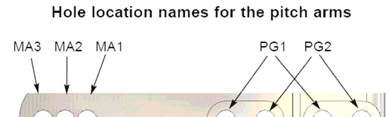
37 AVANT Aurora Ultimate 90 Assembly Manual _37 Holes on the bladegrip and pitch arm affect the delta. Lower delta numbers are more active. Higher delta numbers are more stable. For all the delta settings please see diagram for delta settings in the manual. Holes on the bladegrip and pitch arm affect the delta. Lower delta numbers are more active. Higher delta numbers are more stable. For all the delta settings please see diagram for delta settings in the manual.
38 38 AVANT Aurora Ultimate 90 Assembly Manual Important note: When using Active and Super Active settings the forces applied to the CCPM servos are larger than normal so plastic servo gears can suffer or break. Metal geared high torque servos are strongly recommended for those settings. For pilots that want more precise adjustment of the delta settings here s a guide on how to use the hole locations to vary the setting in small increments. A good starting point for the delta setting is position 7. (4 is Zero delta). # 7 position is achieved using holes number G3 on the bladegrip and holes number PG2 and MA3 (letter A on the drawing below) on the bladegrip pitch arm. Lower numbers make the cyclics less responsive. Higher numbers make them more responsive. (The pink dot indicates the location of the bolts) Note: Most Team pilots are using: MS2, ML2, FB2, G2, PG2 and MA3
.")
39 AVANT Aurora Ultimate 90 Assembly Manual _39 You can use up to 18 different delta settings in this head. Setting pictured in the assembly pictures above corresponds to setting number 7, which is a good point for 3D. Lower delta position numbers = more stability (3D). Higher Delta position numbers = more response. Keep in mind that not all delta setting positions are compatible with all mixing arm ball locations without rod binding against eh flybar cage so those might need to be adjusted.

40 40 AVANT Aurora Ultimate 90 Assembly Manual If you want you can also adjust the phasing to match your blades lead-lag angle and eliminate any tail corkscrewing during rolls if your blades have some. If you need to correct you can start with about 1 degree and build up from there.
. Right ball closer to the right makes it also faster (less flybar stabilization).")
41 AVANT Aurora Ultimate 90 Assembly Manual _41 AV Use two swashplate balls per mixing arm. Use red Loctite here. Left ball closer to the center makes it faster (more swashplate to blades input). Right ball closer to the right makes it also faster (less flybar stabilization). Closer to the center makes it slower (more flybar stabilization). Head Step 6) M3x6mm (4) AV Use two M3x6mm screws to install the arm. Use red Loctite here.
 Use an M3 ball")

42 42 AVANT Aurora Ultimate 90 Assembly Manual Head Step 7) AV AV AV M3x16mm button head screw AV Head Step 8) Use an M3 ball Use blue Loctite here. M4x4 flat point setscrew AV Install the AV mm flybar and secure with two M4 flat point setscrews. Use blue Loctite here.


43 AVANT Aurora Ultimate 90 Assembly Manual _43 Head Step 9) M4x4 flat point setscrew AV AV AV Use two M4 flat point setscrews Head Step 10) M4x10 AV Install two M4 screws onto the Main shaft. Use Red Loctite here and make them very tight.


44 44 AVANT Aurora Ultimate 90 Assembly Manual Head Step 11) AV AV AV AV AV Assemble the washout arm as shown here. Clean any flash with an X-Acto knife and make sure the Y-Link rotates easily around the pin. AV M3x20mm button head screw AV Use the 1mm spacer to install the washout arms. Use blue Loctite here. Do not tighten the washout arm screws too much otherwise the washout base will bind against the shaft. It s designed that way so you can tighten it as the washout base wears out with use.


45 AVANT Aurora Ultimate 90 Assembly Manual _45 Head Step 12) AV Long Ball Link (4) 71 mm distance between the two ball link ends. AV mm threaded rod Install the supplied 85mm threaded rod and leave AV mm threaded rod 3.5 mm distance between the ball link ends. AV Short Ball Link (4) Install the 16mm threaded rod and short ball links. Make sure to align the rod and the mixing arm at 90 degrees when the swashplate is level and blades are at zero degrees or you will end up having more negative pitch than positive pitch. It will also cause the rod to appear too short.
 22.5 mm distance between the ball link ends.")
 AV00-200-659 Install the head button with the")
46 46 AVANT Aurora Ultimate 90 Assembly Manual Head Step 13) AV Long Ball Link (4) 22.5 mm distance between the ball link ends. Head Step 14) Install the 35mm flybar control arm threaded rod and links M3x16 Stainless Steel Screw AV (2) AV Install the head button with the Stainless steel screws. Use blue Loctite here.

47 AVANT Aurora Ultimate 90 Assembly Manual _47 Bag #17: Radio installation For the cases where the servo goes inside the frames here s the method to get it into the frames. Remember to take the rubber grommets of when installing larger servos like the 8717 When installing the servo wires add a couple of layers of heat shrink to the servo wire at the rubber grommet to prevent the frames from chaffing into the wire and creating a short circuit.

48 48 AVANT Aurora Ultimate 90 Assembly Manual AV Thick Ball link AV AV AV Thread the thick ball link into the 50mm threaded rod and use it to glue the threaded rod into the carbon rod with 30-minute. Epoxy or JB Weld. Once cured unthread it and then slide into the brass sleeve using pliers holding the ball link by the flat areas. Once slid into the brass thread is again into the pushrod. This method allows for a tight fit that prevents vibration without the need to glue the brass sleeve.
49 AVANT Aurora Ultimate 90 Assembly Manual _49 Front Tail Control Rod assembly. Repeat process and part numbers from above. AV Tail Pushrod Guide set Install the long pushrod guide toward the front and the short toward the back. If needed after alignment is done use a drop of CA to fix the pushrod guide in place. Install the heat-shrink tubing and once you know where the pushrod guides will be and shrink them using a heat gun. Move the guides forward and back and rotate them accordingly until you reach a point where the pushrod goes from the tail to the frame bellcrank passing through the middle of the pushrod guide holes without touching them. Main Hub assembly Constant Drive Hub assembly
 35mm threaded rod AV00-200-")
 100mm")
50 50 AVANT Aurora Ultimate 90 Assembly Manual AV (2) 85mm threaded rod AV (3) 35mm threaded rod AV (2) 135mm threaded rod AV (4) 80mm threaded rod AV Short Carbon pushrod AV (1) 100mm threaded rod


51 AVANT Aurora Ultimate 90 Assembly Manual _51 Recommended threaded rod distances. All distances indicated below refer to distances from end to end of ball links. Different servo brands will cause distances to differ from the ones listed below. 3.5mm x 2 71mm x mm x mm x 3 Gyro cable routing slots Gyro cable routing slots 120mm x 2 Gyro cable routing slots
52 52 AVANT Aurora Ultimate 90 Assembly Manual IMPORTANT Note: All the servo arms used on the cyclic servos should have a center-to-hole distance of 12.5mm to 13mm mm x mm x 2 Cut wheel off as shown to prevent binding with the ball link 83.5mm x 1


53 AVANT Aurora Ultimate 90 Assembly Manual _53 Ball links fit and sizing. If needed for a final fit you can squeeze the ball link ring slightly with some pliers to make it a bit loser. Keep in mind that the important thing is to make sure your ball links are secure so check and make sure the balls don t come out easily. Canopy and Decals. Open four 3/8 (9.5mm) holes with either a hole punch (preferred) or a drill bit and install the four rubber grommets.
AVANT Aurora Ultimate 90
 2 AVANT Aurora Ultimate 90 Assembly Manual AVANT Aurora Ultimate 90 Assembly Manual V1.08 LIABILITY DISCLAIMER This kit is for a radio controlled (RC) helicopter. RC Helicopters are not toys. Moving parts
Specifications ASSEMBLY INSTRUCTIONS
 ASSEMBLY INSTRUCTIONS Specifications Length : 6 mm Height : 218 mm Main Blade : 325 mm Main Rotor Diameter : 723 mm Tail Rotor Diameter : 150 mm Motor Pinion Gear : 16T (14T) Main Drive Gear : 150T Main
Hawk Sport. Quick Build Guide. Century Helicopter Products. Designed and Developed in USA
 Hawk Sport Quick Build Guide This Century HAWK SPORT kit comes in a QUICK BUILD format that has most of the major systems already assembled into sub-assemblies. These are packed seperately into their specific
Assembly instructions
 Assembly instructions Step up to Excellence with X-cell 2 Table of Contents Kit Introduction...4 R/C Helicopter Safety...4 Warning...4 General Guidelines...4 Academy of Model Aeronautics (AMA)...5 Kit
Manual GLOGO
 Manual GLOGO 690 www.mikado-heli.de Mikado Model Helicopters GmbH Graf-von-Schwerin-Str. 40 14469 Potsdam Germany phone +49 (0)331 3749-0 fax +49 (0)331 3749-11 www.mikado-heli.de Mikado Model Helicopters
TABLE OF CONTENTS INTRODUCTION 3 CUSTOMER SERVICE 4 FEATURES 5 FRE-ASSEMBLY INFORMATION 6 REQUIRED TOOLS 7 HARDWARE & OPTIONAL ACCESSORIES 8
 Page 1 of 84 TABLE OF CONTENTS INTRODUCTION 3 CUSTOMER SERVICE 4 FEATURES 5 FRE-ASSEMBLY INFORMATION 6 REQUIRED TOOLS 7 HARDWARE & OPTIONAL ACCESSORIES 8 OTHER HARDWARE & OPTIONAL ACCESSORIES 9 OTHER REQUIREMENTS
RECOMMENDED MOTOR AND BATTERY SET UP
 SPECIFICATION - Wingspan: 1404mm (55.3in) - Length: 1134mm (44. 6 in) - Flying weight: 3.2-3.4 kg - Covering type: Genuine ORACOVER - Spinner size: scale type (not included) - Radio: 4 channel minimum
Newsletter. New Product Information New Design & Specification Miscellaneous July 10. Availability:
 The very high agility and the maximum power of the Titan X50 is, because of the optimum weight and the great main rotor head perfect. The result is a lot of fun in flying hard 3D. In addition the precision
Turbinator-2 Build Manual
 Turbinator-2 Build Manual Thank you for your purchase of the Turbinator-2 sport jet by Boomerang RC Jets. This RC Jet IS NOT A TOY and should only be flown and operated by experienced RC Turbine Pilots.
Instruction Manual. Wingspan : 2270mm (89.37 inches) : 1870mm (73.62 inches) : 7400gr gr. : 4 channel - 6 standard servo.
 : 1870mm (73.62 inches) : 7400gr gr. : 4 channel - 6 standard servo.") Wingspan : 2270mm (89.37 inches) g Length : 1870mm (73.62 inches) Weight : 7400gr - 7600gr Radio : 4 channel - 6 standard servo Engine : 25cc-35cc KIT CONTENTS: We have organized the parts as they come
Wingspan : 2270mm (89.37 inches) g Length : 1870mm (73.62 inches) Weight : 7400gr - 7600gr Radio : 4 channel - 6 standard servo Engine : 25cc-35cc KIT CONTENTS: We have organized the parts as they come
Assembly Manual. 1/10th Formula 1 Car
 Assembly Manual 1/10th Formula 1 Car Center Pivot Bag 1 3374 - Center Pivot Socket 40194 - Hard Anodized Alum Pivot ball 3254-2-56 *Note - Sometimes it is helpful to slightly over-tighten the top clamp
Instruction Manual. Specification:
 Instruction Manual L O W Specification: Wingspan: 133 cm (52.3 inches) Length : 104 cm (40.9 inches) Weight : 1790gr Engine : 25-32 two stroke Radio : 4 channel - 4 servo W I N G KIT CONTENTS: We have
Maintenance Information
 Form 16575334 Edition 1 April 2005 Electric Screwdrivers EL, EP and ET 34V DC Series Maintenance Information Save These Instructions WARNING Maintenance procedures have the potential for severe shock hazard
Pitts Challenger m (100cc) MANUAL
 MANUAL") Pitts Challenger 87 2.20m (100cc) MANUAL 1- Introduction: WELCOME TO THE PILOT-RC TEAM! Thank you for choosing a Pilot-Rc plane as your next model. We hope that you enjoy many successful and exhilarating
Pitts Challenger 87 2.20m (100cc) MANUAL 1- Introduction: WELCOME TO THE PILOT-RC TEAM! Thank you for choosing a Pilot-Rc plane as your next model. We hope that you enjoy many successful and exhilarating
1660mm (65.4 in) 1200mm (47.2 in) 2700gr gr 6 channel - 7 servo standard 46/ 2 stroke or 52/ 4 stroke
 1200mm (47.2 in) 2700gr gr 6 channel - 7 servo standard 46/ 2 stroke or 52/ 4 stroke") Instruction Manual CESSNA-46 1660mm (65.4 in) 1200mm (47.2 in) 2700gr - 3000gr 6 channel - 7 servo standard 46/ 2 stroke or 52/ 4 stroke KIT CONTENTS: We have organized the parts as they come out of the
Instruction Manual CESSNA-46 1660mm (65.4 in) 1200mm (47.2 in) 2700gr - 3000gr 6 channel - 7 servo standard 46/ 2 stroke or 52/ 4 stroke KIT CONTENTS: We have organized the parts as they come out of the
Assembly instructions
 Assembly instructions Step up to Excellence with X-cell 2 Table of Contents Kit Introduction...4 R/C Helicopter Safety...4 Warning...4 General Guidelines...4 Academy of Model Aeronautics (AMA)...5 Kit
RECOMMENDED MOTOR AND BATTERY SET UP
 SPECIFICATION - Wingspan: 6000mm (236.2 in) - Length: 2873mm (113.1 in) - Flying weight: 14-18 kg - Wing area: 219.4 dm2 - Wing loading: 64g/dm2 - Wing type: HQ airfoils - Covering type: Genuine ORACOVER
MS:176 ASSEMBLY MANUAL. Graphics and specifications may change without notice.
 ASSEMBLY MANUAL MS:176 Graphics and specifications may change without notice. Specifications: Wing span ------------------------------98.4in (250cm). Wing area ----------------1576.4sq.in (101.7sq dm).
: 7 channel - 9 servo, Hi-Torque ( Minimum 6 kg ).
.") g Wingspan : 1820mm (71.65 inches) Length : 1625mm (63.98 inches) Weight : 6900gr Engine : 25cc - 35cc Radio : 7 channel - 9 servo, Hi-Torque ( Minimum 6 kg ). KIT CONTENTS: We have organized the parts
g Wingspan : 1820mm (71.65 inches) Length : 1625mm (63.98 inches) Weight : 6900gr Engine : 25cc - 35cc Radio : 7 channel - 9 servo, Hi-Torque ( Minimum 6 kg ). KIT CONTENTS: We have organized the parts
Instruction Manual book
 book ITEM CODE:BH 115. SPECIFICATION Wingspan : 6,000 mm 236,22 in. Length : 2,740 mm 107,87 in. Weight : 17.5kg 38.5Lbs. Radio : 08 channels. Servo : 07-08 HS-5685MH(HITEC) Battery : 2 Cells-Li-Po 7.4V
8-3 MAIN ROTOR BLADE ATTACHMENT (BLADES NOT INCLUDED)
") 8-3 MAIN ROTOR BLADE ATTACHMENT (BLADES NOT INCLUDED) Two sets required Socket Head Bolt, 4 x 35 mm...2 pcs Hold the 4 mm Lock Nut while tightening using a Wiha 7 mm Nut Driver or equivalent. Lock Nut,
8-3 MAIN ROTOR BLADE ATTACHMENT (BLADES NOT INCLUDED) Two sets required Socket Head Bolt, 4 x 35 mm...2 pcs Hold the 4 mm Lock Nut while tightening using a Wiha 7 mm Nut Driver or equivalent. Lock Nut,
ALMOST READY TO FLY. Wing Span in cm. 2
 ASSEMBLY MANUAL ALMOST READY TO FLY MS:X9 Specifications Wing Span --------------------------61.4 in ---------------------------156cm. 2 Wing Area --------------------------606.1 sq.in ------------------
Instruction Manual book
 book Item code:bh131 SPECIFICATION Wingspan : 3,000 mm 118.1 in. Length : 1,600 mm 62.99 in. Weight : 2.2 kg 4.84 Lbs. Radio : 05 channels. Servo : 06 mini servos. Electric Motor: BOOST 40 Battery : 3celIs
V Specification
 V1.0.2 Specification Factory configured CNC torque tube and tail boom assembly. Indexed holes on Main Shaft Bearing Blocks allow precision fit with minimal freeplay. One piece CNC open tail box for maximum
MiG-29 Retract Kit (for the HET-RC Mini Air Retract System)
") MiG-29 Retract Kit (for the HET-RC Mini Air Retract System) The MiG-29 Retract Kit was designed to allow the easy installation of the HET-RC mini Air Retract system into the twin EDF MiG-29. We recommend
MiG-29 Retract Kit (for the HET-RC Mini Air Retract System) The MiG-29 Retract Kit was designed to allow the easy installation of the HET-RC mini Air Retract system into the twin EDF MiG-29. We recommend
Instruction Manual. Wingspan : 1400 mm (55.12 inch) : 1480 mm (58.27 inch) : 5500gr gr. : 6-9 channel/ 8 servo high torque,1 standard
 : 1480 mm (58.27 inch) : 5500gr gr. : 6-9 channel/ 8 servo high torque,1 standard") Wingspan : 1400 mm (55.12 inch) g Length : 1480 mm (58.27 inch) Weight : 5500gr - 6000gr Radio : 6-9 channel/ 8 servo high torque,1 standard Engine : GT 22 OS KIT CONTENTS: We have organized the parts
Wingspan : 1400 mm (55.12 inch) g Length : 1480 mm (58.27 inch) Weight : 5500gr - 6000gr Radio : 6-9 channel/ 8 servo high torque,1 standard Engine : GT 22 OS KIT CONTENTS: We have organized the parts
RECOMMENDED MOTOR AND BATTERY SET UP
 SPECIFICATION - Wingspan: 1410mm (55.5 in) - Length: 1278mm (50.3 in) - Flying weight: 3.2-3.4 kg - Wing area: 41.3 dm2 - Wing loading: 75g/dm2 - Wing type: Naca airfoils - Covering type: Genuine ORACOVER
Instruction Manual book
 Instruction Manual book ITEM CODE:BH118. SPECIFICATION Wingspan : 1,050 mm 41.34 inches. Length : 950mm 37.4 inches. Weight : 1 kg 2.2 lbs. Radio : 04 channels. Servo : 4 mini servos. Motor : KMS 2814/05
Instruction Manual. Wingspan : 1400mm (55.12 in) : 1370mm (53.94 in) : 2600gr gr. : 4 channel / 5 servo. : / 2 stroke_52-71 / 4 stroke
 : 1370mm (53.94 in) : 2600gr gr. : 4 channel / 5 servo. : / 2 stroke_52-71 / 4 stroke") Instruction Manual 540 Wingspan : 1400mm (55.12 in) g Length : 1370mm (53.94 in) Weight : 2600gr - 2800gr Radio : 4 channel / 5 servo Engine : 46-52 / 2 stroke_52-71 / 4 stroke KIT CONTENTS: We have organized
Instruction Manual 540 Wingspan : 1400mm (55.12 in) g Length : 1370mm (53.94 in) Weight : 2600gr - 2800gr Radio : 4 channel / 5 servo Engine : 46-52 / 2 stroke_52-71 / 4 stroke KIT CONTENTS: We have organized
I/C FLIGHT GUIDELINES
 SPECIFICATION - Wingspan: 3500mm (137.8 in) - Length: 1650mm (64.96 in) - Flying weight: 3700-4000 gr - Wing area: 75 dm2 - Wing loading: 49g/dm2 - Wing type: HQ profile - Covering type: Genuine ORACOVER
I n s t r u c t i o n M a n u a l. Instruction Manual SPECIFICATION
 I n s t r u c t i o n M a n u a l Instruction Manual SPECIFICATION - Wingspan: 3200mm (125,9 in) - Length: 1650mm (64,9 in) - Flying weight: 3000gr 3200gr - Wing area: 64.5 dm2 - Wing loading: 46g/dm2
INTRODUCTION 3 CUSTOMER SERVICE 4 FEATURES 5 FRE-ASSEMBLY INFORMATION 6 REQUIRED TOOLS 7 HARDWARE & OPTIONAL ACCESSORIES 8
 Page 1 of 69 TABLE OF CONTENTS INTRODUCTION 3 CUSTOMER SERVICE 4 FEATURES 5 FRE-ASSEMBLY INFORMATION 6 REQUIRED TOOLS 7 HARDWARE & OPTIONAL ACCESSORIES 8 OTHER HARDWARE & OPTIONAL ACCESSORIES 9 OTHER REQUIREMENTS
: 6 channel - 9 servo
 g Wingspan : 2005mm (78.94 inches) Length : 1640mm (64.57 inches) Weight : 6400g - 6600g Engine : 25cc - 35cc Radio : 6 channel - 9 servo KIT CONTENTS: We have organized the parts as they come out of
ASSEMBLY MANUAL. Kit features. MS:76
 ASSEMBLY MANUAL MS:76 Graphics and specfications may change without notice. Specifications: Wingspan---------------------------------------------------- 82.8 in------------------------------------- 210.3cm.
$1.00 FOR THE TQIO/RCIO
 $1.00 FOR THE TQIO/RCIO m mm HDBBYSHOP Champion Jay Halsey has an impressive track record. One of Jay's advantages is a whisper smooth tranny thanks to his dad, Jim. Now you can build a Halsey transmission!
RIGGING THE FLIGHT CONTROLS
 RIGGING THE FLIGHT CONTROLS Rigging refers to the installation and adjustment of the rods that move flight surfaces in response to inputs from the controls of the helicopter. These rods are cut to length,
Trainer Assembly Manual
 Trainer Assembly Manual www.pilot-rc.com -Pilot Trainer- 1 -Pilot Trainer- 2 -Pilot Trainer- 3 -Preliminary i wing & stab assembly- 1-) Locate both Plywood wing joiners (Large and small one) 2-) Insert
Manual LOGO 550 SE.
 Manual LOGO 550 SE www.mikado-heli.de Mikado Model Helicopters GmbH Friedrich-Klausing-Straße 14469 Potsdam Germany phone +49 (0)331 3749-0 fax +49 (0)331 3749-11 www.mikado-heli.de Mikado Model Helicopters
Instruction Manual book
 Instruction Manual book SPECIFICATION Wingspan : 1,800mm. 70.87 in. Length : 1,350 mm. 53.15in. Weight : 3.6kg. 7.92lbs. Parts Listing required (not included). Glow Engine : 55-61 2 stroke. 91 4 stroke.
Instruction Manual book
 Instruction Manual book ITEM CODE:BH118. SPECIFICATION Wingspan : 1,050 mm 41.34 inches. Length : 950mm 37.4 inches. Weight : 1 kg 2.2 lbs. Radio : 04 channels. Servo : 4 mini servos. Motor : BL2215/20
Instruction Manual book
 book SPECIFICATION Wingspan : 1,450 mm 57.09 in. Length : 1,200mm 47.24in. Weight : 3.1 kg 6.82 Lbs. Radio : 05 channels. Servo : 07 servos. Engine : 61-75 2 stroke. 91 4 stroke. Made in Vietnam. This
(Glider) ASSEMBLY MANUAL
 ASSEMBLY MANUAL") (Glider) MS:132 ASSEMBLY MANUAL Graphics and specifications may change without notice. Specifications: Wing span ------------------------------118.1in (300cm). Wing area ---------------------902.1sq.in
(Glider) MS:132 ASSEMBLY MANUAL Graphics and specifications may change without notice. Specifications: Wing span ------------------------------118.1in (300cm). Wing area ---------------------902.1sq.in
SIZE.120 OR 30CC SCALE 1:5 ARF
 PC21 PILATUS MK2 SIZE.120 OR 30CC SCALE 1:5 ARF SPECIFICATION - Wingspan: 1772mm (69.72in) - Length: 2019mm (79.5 in) - Flying weight: 6.4-7.2 kg - Wing area: 57.6 dm2 - Wing loading: 113g/dm2 - Wing type:
INSTRUCTION MANUAL BOOK
 INSTRUCTION MANUAL BOOK ITEM CODE BH57. SPECIFICATION Wingspan: 1,470 mm. 57.87 in. Length : 1,180 mm. 46.46 in. Weight : 2.7 Kg. 5.94 Lbs. Engine : 46 cu.in 2 stroke. 52 cu.in 4 stroke. Radio : 4 channels.
Welcome to VBar Express 5.3
 Bar Express Welcome to VBar Express 5.3 The VBar with V 5.3 Express software is an innovative product setting new standards for model helicopters in terms of flight performance and programming capacity.
Husqvarna Hedgetrimmers 325HS/ 325HE/ 325HDA. Workshop manual
 Husqvarna Hedgetrimmers 325HS/ 325HE/ 325HDA Workshop manual 101 90 73-26 2 Workshop Manual Hedge trimmers Supplement for models 325HS, 325HE,325HDA Contents 1. Starter 5 2. Ignition system 7 3. Fuel system
Maintenance Information
 80234313 Edition 1 June 2006 Air Grinder, Die Grinder, Sander and Belt Sander Series G1 (Angle) Maintenance Information Save These Instructions WARNING Always wear eye protection when operating or performing
to fly. Most hardware included and all replacement parts are available.
 Instruction Manual The Thunderbolt P47 was perhaps the greatest of world war II in terms of all round performance and capability Phoenix Model has recreated a 2C - 60 class engine (or 4c 91 class) It was
Amarillo PUMP DRIVES (250 HP THROUGH 350 HP) INSTRUCTIONS FOR REPAIRING MODELS 250, 300, and 350
 INSTRUCTIONS FOR REPAIRING MODELS 250, 300, and 350") Amarillo PUMP DRIVES (250 HP THROUGH 350 HP) INSTRUCTIONS FOR REPAIRING MODELS 250, 300, and 350 Amarillo Right Angle Pump Drives, if properly installed and maintained, should provide years of service
Amarillo PUMP DRIVES (250 HP THROUGH 350 HP) INSTRUCTIONS FOR REPAIRING MODELS 250, 300, and 350 Amarillo Right Angle Pump Drives, if properly installed and maintained, should provide years of service
51in Aerobatic Series Sukhoi SU-26M Almost-Ready-to-Fly. Instruction Manual. Specifications
 51in Aerobatic Series Sukhoi SU-26M Almost-Ready-to-Fly Instruction Manual Specifications Wingspan: 51.2 in (1300mm) Length: 51.2 in (1300mm) Wing Area: 581 sq in (37.5sq dm) Flying Weight: 3.5 lb (1600g)
Maintenance Information
 80234313 Edition 2 May 2014 Air Grinder, Die Grinder, Sander and Belt Sander Series G1 (Angle) Maintenance Information Save These Instructions Product Safety Information WARNING Failure to observe the
Instruction Manual BULLDOG. Wingspan : 1410 mm (55.5in) : 1450 mm (57.1in) : 4900gr gr. Weight. : 6-9 Channel/ 7 servo high torque, 1standard
 : 1450 mm (57.1in) : 4900gr gr. Weight. : 6-9 Channel/ 7 servo high torque, 1standard") Wingspan : 1410 mm (55.5in) Length Weight Radio Engine : 1450 mm (57.1in) : 4900gr - 5600gr : 6-9 Channel/ 7 servo high torque, 1standard : 1.20/ 2 stroke 1.80/ 4 stroke KIT CONTENTS: We have organized
Wingspan : 1410 mm (55.5in) Length Weight Radio Engine : 1450 mm (57.1in) : 4900gr - 5600gr : 6-9 Channel/ 7 servo high torque, 1standard : 1.20/ 2 stroke 1.80/ 4 stroke KIT CONTENTS: We have organized
Sport Model with an easy-lube spindle
 1. List of tools: Back To Top 1. Safety glasses 2. Hammer 3. Brass or aluminum punch 4. channel locks 5. Block of wood or plastic 6. grease gun 7. razor knife 8. 6" long, 2" diameter or 1 ½" diameter pipe
Manual LOGO 600 SE.
 Manual LOGO 600 SE www.mikado-heli.de Mikado Model Helicopters GmbH Friedrich-Klausing-Straße 4469 Potsdam Germany phone +49 (0) 749-0 fax +49 (0) 749- www.mikado-heli.de Mikado Model Helicopters GmbH
ALMOST READY TO FLY. Wing Span in cm. 2
 ASSEMBLY MANUAL ALMOST READY TO FLY MS: X12 A - B Graphics and specfications may change without notice. Kit features. Specifications Wing Span ------------------------------- 42.7 in ---------------------
RADIO CONTROL MODEL HURRICANE
 RADIO CONTROL MODEL VQAA040G VQAA040B HURRINE Almost ready to fly SPECIFITIONS Wingspan...63 in. / 161cm Length...50 in. / 129cm Engine...50~60 2T / 70~90 4T Or Electric equivalent. RC Functions: Motor
MS:183 ASSEMBLY MANUAL. Graphics and specifications may change without notice.
 MS:183 ASSEMBLY MANUAL Graphics and specifications may change without notice. Specifications: Wing span ------------------------------79.9in (203cm). Wing area -----------------1165.6sq.in (75.2sq dm).
Instruction Manual. Wingspan : 1694mm (66.69 in) : 1470mm (57.87 in) : 3200gr gr. : 61 two stroke/ 71 four stroke. : 6 channel / 7 servo
 : 1470mm (57.87 in) : 3200gr gr. : 61 two stroke/ 71 four stroke. : 6 channel / 7 servo") Wingspan : 1694mm (66.69 in) g Length : 1470mm (57.87 in) Weight : 3200gr - 3800gr Engine : 61 two stroke/ 71 four stroke Radio : 6 channel / 7 servo KIT CONTENTS: We have organized the parts as they
Wingspan : 1694mm (66.69 in) g Length : 1470mm (57.87 in) Weight : 3200gr - 3800gr Engine : 61 two stroke/ 71 four stroke Radio : 6 channel / 7 servo KIT CONTENTS: We have organized the parts as they
Section 13. Tail Rotor Drive. RotorWay International A600 TALON Construction Manual. Section 13. Page A
 RotorWay International Page A Tail Rotor Drive Procedures covered in this section: Install driveshafts and gearboxes; install drive belt and tensioner; fabricate and install tail rotor pitch actuator arms;
Instruction Manual. Wingspan : 1884 mm (74.17 in) Length. Weight. Engine. : 4 channels / 5 servo standard. : 1450 mm (57.
 Length. Weight. Engine. : 4 channels / 5 servo standard. : 1450 mm (57.") Wingspan : 1884 mm (74.17 in) Length : 1450 mm (57.09 in) Weight : 4000 gr Engine : 60 two strokes Radio : 4 channels / 5 servo standard KIT CONTENTS: We have organized the parts as they come out of the
Wingspan : 1884 mm (74.17 in) Length : 1450 mm (57.09 in) Weight : 4000 gr Engine : 60 two strokes Radio : 4 channels / 5 servo standard KIT CONTENTS: We have organized the parts as they come out of the
Instruction Manual book
 book SPECIFICATION Wingspan : 1,920 mm 75.59 in. Length : 1,560 mm 61.42 in. Weight : 5 kg 11.00Lbs. Radio : 06 channels. Servo : 09 servos. Engine : 120 4 stroke. Made in Vietnam. This instruction manual
MS:159 ASSEMBLY MANUAL. Graphics and specifications may change without notice.
 ASSEMBLY MANUAL MS:159 Graphics and specifications may change without notice. Specifications: Wing span ----------------------------61.8in (157cm). Wing area -----------------1100.5sq.in (71.0sq dm). Weight
RECOMMENDED EDF AND BATTERY SET UP
 SPECIFICATION - Wingspan: 1150mm (45.3 in) - Length: 1587mm (62.5 in) - Flying weight: 5.0-5.3 kg - Wing area: 40dm2 - Wing loading: 125g/dm2 - Wing type: Naca airfoils - Covering type: Genuine ORACOVER
RECOMMENDED MOTOR AND BATTERY SET UP
 SPECIFICATION - Wingspan: 2190mm (86.2 in) - Length: 1907mm (75 in) - Flying weight: 9000-12000 gr - Wing area: 92 dm2 - Wing loading: 98g/dm2 - Wing type: Naca airfoils - Retract gear type: Air-retract
Radio control model INSTRUCTION MANUAL PYLON RACING. Wingspan: 1148mm (45.2 ) Radio : 4 channels Engine : two-stroke
 Radio : 4 channels Engine : two-stroke") VQA038 VQA039 Radio control model INSTRUCTION MANUAL MAGIC PYLON RACING Wingspan: 1148mm (45.2 ) Radio : 4 channels Engine :.25 -.32 two-stroke WARNING! This radio control model is not a toy. If modified
VQA038 VQA039 Radio control model INSTRUCTION MANUAL MAGIC PYLON RACING Wingspan: 1148mm (45.2 ) Radio : 4 channels Engine :.25 -.32 two-stroke WARNING! This radio control model is not a toy. If modified
MS:158 ASSEMBLY MANUAL. Graphics and specifications may change without notice.
 MS:158 ASSEMBLY MANUAL Graphics and specifications may change without notice. Specifications: Wing span ------------------------------70.9in (180cm). Wing area -----------------644.8sq.in (41.6sq dm).
OWNER'S MANUAL 2000 & ROAR National Champion
 2000 & 2001 ROAR National Champion OWNER'S MANUAL Carefully read through all instructions to familiarize yourself with the parts, construction techniques, and tuning tips outlined in this manual. Being
Instruction Manual book
 Instruction Manual book Item code:bh133 SPECIFICATION Wingspan : 1,400 mm 55.12 in. Length : 1,350 mm 53.15 in. Weight : 3.7 kg 8.14 Lbs. Radio : 08-09 channels. Servo : 08-09 servos. EDF : Turingy SK3
Bag 1. Bag 1. Center Pivot. Center Pivot
 8 00734 01901 5 Center Pivot Bag 1 3374 - Center Pivot Socket 4019 - Alum Pivot ball 3254-2-56 Button Head *Note - Sometimes it is helpful to slightly over-tighten the top clamp screws, then work the ball
LPE C5 Battery Relocation Kit
 LPE C5 Battery Relocation Kit The LPE C5 Corvette battery relocation kit improves vehicle weight distribution by moving weight to the rear of the vehicle. The improved weight distribution increases traction
EXTRA 330LX. Specifications: Code: SEA274. Graphics and specifications may change without notice. ASSEMBLY MANUAL
 ASSEMBLY MANUAL EXTRA 330LX Code: SEA274 Graphics and specifications may change without notice. Specifications: Wingspan---------------82.0 in (208.2 cm). Wing area---------------1349.4 sq.in ( 87.1 sq.dm).
SOXOS DB7. Words & Pictures: Raquel Bellot
 SOXOS DB7 Words & Pictures: Raquel Bellot The Soxos DB7, Swiss brand Heli Professional's flagship helicopter. Specifically, it started life as a Soxos 700 which was modified and updated by world champion
J & D Machine / Hyperdrive / MSA 3711 Moon Bend Rd. Chapel Hill, TN 37034
 J & D Machine / Hyperdrive / MSA 3711 Moon Bend Rd. Chapel Hill, TN 37034 www.hyperdriveracing.com 1 You now own a state of the art 1/10 scale oval race car. The Hyperdrive Assault has gone through months
Table of Contents. Tail Wheel Assembly Installation.. page 01. Stabilizer Installation.. page 02. Fin Installation.. page 03
 Table of Contents Tail Wheel Assembly Installation.. page 01 Stabilizer Installation.. page 02 Fin Installation.. page 03 Elevator and Rudder Hinge Installation.. page 04 Rudder Controls.. page 05 Elevator
DRIVE AXLE Volvo 960 DESCRIPTION & OPERATION AXLE IDENTIFICATION DRIVE AXLES Volvo Differentials & Axle Shafts
 DRIVE AXLE 1994 Volvo 960 1994 DRIVE AXLES Volvo Differentials & Axle Shafts 960 DESCRIPTION & OPERATION All 960 station wagon models use type 1041 rear axle assembly. All 960 4-door models use type 1045
the leading edge of the wing, at the fuselage - Length: 1540mm (60.6 in) 10% expo; High: 15mm up/down, 10% expo - Wing area: 40dm2
 10% expo; High: 15mm up/down, 10% expo - Wing area: 40dm2") SPECIFICATION - Gravity CG: 165-170 mm (6.5-6.7 in) Back from - Wingspan: 1400mm (55.1 in) the leading edge of the wing, at the fuselage - Length: 1540mm (60.6 in) - Control throw Ailerons: Low: 12mm up/down,
SPECIFICATION - Gravity CG: 165-170 mm (6.5-6.7 in) Back from - Wingspan: 1400mm (55.1 in) the leading edge of the wing, at the fuselage - Length: 1540mm (60.6 in) - Control throw Ailerons: Low: 12mm up/down,
RECOMMENDED MOTOR AND BATTERY SET UP
 SPECIFICATION - Wingspan: 1800mm (70.8 in) - Length: 1355mm (53.3 in) - Flying weight: 4100-4300 g - Wing area: 51 dm2 - Wing loading: 80g/dm2 - Wing type: Naca airfoils - Covering type: Genuine ORACOVER
ASSEMBLY MANUAL. Kit features. MS:110
 MS:110 ASSEMBLY MANUAL Graphics and specifications may change without notice. Specifications: Wing span-------------------------------------------------- 62.9 in---------------------------------------
Index. Experience in handling and fl ying arc Helicopter are required in order to operate a LOGO 480. Minimum Age : 14 Years
 Manual Mikado Model Helicopters GmbH Graf-von-Schwerin-Str.40 14469 Potsdam Germany phone +49 (0)331 23749-0 fax +49 (0)331 23749-11 www.mikado-heli.de Mikado Model Helicopters GmbH 2016, V1.0023 Index
Instruction Manual book
 book ITEM CODE:BH 145 SPECIFICATION Wingspan: 6,000mm 236.22 in. Length : 2,800 mm 110.24 in. Weight : 18.5 kg 40.7 Lbs. Parts listing required (not included). Radio : 07-08 channels. Servo : 09-10 standard
Owners Manual Assembly Instructions
 Owners Manual Assembly Instructions Rev. 3 2 INTREPID 60 Table Of Contents PARTS LIST... 10 LOWER FRAMES... 16 BATTERY TRAY/ SWITCH MOUNT... 17 LANDING GEAR ASSEMBLY AND MOUNTING... 18 ENGINE PREPARATION...
OWNER'S MANUAL Magnolia Ave., Chino, CA phone: (909) fax: (909)
 fax: (909)") OWNER'S MANUAL Carefully read through all instructions to familiarize yourself with the parts, construction techniques, and tuning tips outlined in this manual. Being able to grasp the overall design of
OWNER'S MANUAL Carefully read through all instructions to familiarize yourself with the parts, construction techniques, and tuning tips outlined in this manual. Being able to grasp the overall design of
RECOMMENDED MOTOR AND BATTERY SET UP
 SPECIFICATION - Wingspan: 2000mm (78.7in) - Length: 1544mm (60.7 in) - Flying weight: 3600-3800 gr - Wing area: 66 dm2 - Wing loading: 55g/dm2 - Wing type: Naca airfoils - Covering type: Genuine ORACOVER
ARF. Specifications: ASSEMBLY MANUAL MS: 193. Graphics and specifications may change without notice.
 ASSEMBLY MANUAL Graphics and specifications may change without notice. MS: 193 ARF Specifications: Wingspan---------------62.0 in (157.5 cm). Wing area----------------620 sq.in (40.0 sq.dm). Weight-------------------3.3-3.9
ASSEMBLY MANUAL SIZE: 46-62
 SIZE: 46-62 MS:199 ASSEMBLY MANUAL Graphics and specifications may change without notice. Specifications: Wing span ------------------------------54.9 in ( 139.5cm). Wing area -----------------517.7 sq.in
Instruction Manual. Wingspan : 1670mm. : 3400gr gr. : 61/75 two stroke. : 5 servo + 1 servo retract / 6 channel
 Wingspan : 1670mm g Length Weight Engine Radio : 1350mm : 3400gr - 4000gr : 61/75 two stroke : 5 servo + 1 servo retract / 6 channel KIT CONTENTS: We have organized the parts as they come out of the box
Installation Manual TWM Performance Short Shifter Cobalt SS/SC, SS/TC, HHR SS, Ion Redline and Saab 9-3
 Page 1 Installation Manual TWM Performance Short Shifter Cobalt SS/SC, SS/TC, HHR SS, Ion Redline and Saab 9-3 Please Note: It is preferable to park on a flat surface, as you will have to engage and disengage
XCell Fury Extreme Assembly Manual
 XCell Fury Extreme Assembly Manual Version 1.0 Created: 11/14/2006 Copyright Miniature Aircraft US For More Information contact: Miniature Aircraft USA 31713 Long Acres Drive Sorrento, FL 32776 USA Phone
LOGO 400 V-Stabi. Manual.
 Manual www.mikado-heli.de LOGO 400 V-Stabi Mikado Modellhubschrauber Friedrich-Klausing-Straße 2 14469 Potsdam Germany Phone +49 (0)331 23749-0 Fax +49 (0)331 23749-11 www.mikado-heli.de Mikado Modellhubschrauber,
MAXI LIFT. 33cc ASSEMBLY MANUAL. ALMOST READY TO FLY. Specifications: MS: 209
 WWWSEAGULLMODELSCOM ASSEMBLY MANUAL MAXI LIFT 33cc Graphics and specifications may change without notice MS: 209 ALMOST READY TO FLY Specifications: Wingspan---------------876 in (2222 cm) Wing area----------------10726sqin
Instruction Manual book
 book SPECIFICATION Wingspan : 2,080 mm 81.89 in. Length : 1,680 mm 66.14 in. Weight : 6.2 kg 13.64 Lbs. Radio : 06 channels. Servo : 06 servos. Engine : 30-35 CC Gas(FUJI IMVAC). Made in Vietnam. This
Instruction Manual book
 Instruction Manual book ITEM CODE:BH135 SPECIFICATION Wingspan : 4,200mm. 163.35 in. Length : 2,100 mm. 82.68 in. Weight : 7,6 kg. 16.72lbs Radio : 07 channels. Servo : 05 06 standard high torque servos,
RHINO SUSPENSION SYSTEM INSTALLATION INSTRUCTIONS
 PARTS INCLUDED: 2 FRONT UPPER A-ARMS 2 FRONT LOWER A-ARMS 2 UNI-BALL JOINTS 2 UNI-BALL JOINT STUDS 2 UNI-BALL JOINT CAPS 2 RETAINING RINGS 1 FRONT SHOCK ASSEM. 2 DELRON STEERING STOPS 2 SHOCK MOUNT SPACERS
MS:136 ASSEMBLY MANUAL. Graphics and specifications may change without notice.
 ASSEMBLY MANUAL MS:136 Graphics and specifications may change without notice. Specifications: Wing span ----------------------------79.5in (202cm). Wing area -----------------965.7sq.in (62.3sq dm). Weight
INSTRUCTION MANUAL WARRANTY
 INSTRUCTION MANUAL Rotor Diameter: 23 in [588mm] Weight: 20.5 23 oz [580 650 g] Length: 25 in [630mm] Height: 9 in [225mm] Motor: 200W brushless, 28mm diameter Heli-Max guarantees this kit to be free from
MS:190 ASSEMBLY MANUAL. Graphics and specifications may change without notice.
 ASSEMBLY MANUAL MS:190 Graphics and specifications may change without notice. Specifications: Wing span -----------------------------49.2.in (125cm). Wing area -----------------415.4sq.in (26.8sq dm).
Instruction Manual book
 Instruction Manual book SPECIFICATION Wingspan : 1,920 mm 75.59 in. Length : 1,560 mm 61.42 in. Weight : 5 kg 11.00Lbs. Radio : 06 channels. Servo : 09 servos. Engine : 120 4 stroke. Made in Vietnam. JU87-STUKA
 WWW.SEAGULLMODELS.COM ASSEMBLY MANUAL Graphics and specifications may change without notice. Code: SEA232 Specifications: Wingspan---------------70.9 in (180 cm). Wing area---------------810.3 sq.in (52.3
AVIATOR 25 ARF Almost Ready-to-Fly
 AVIATOR 25 ARF Almost Ready-to-Fly Instruction Manual Specifications Wingspan: 54.3 in (1380mm) Length: 45.2 in (1150mm) Wing Area: 438 sq in (34sq dm) Flying Weight: 3.8 b (1700g) Dear Customer, Congratulations
Instruction Manual book
 Instruction Manual book SPECIFICATION Wingspan : 1,920 mm 75.59 in. Length : 1,560 mm 61.42 in. Weight : 5 kg 11.00Lbs. Radio : 06 channels. Servo : 09 servos. Engine : 120 4 stroke. Made in Vietnam. JU87-STUKA