Assembly instructions
|
|
|
- Dominic Copeland
- 6 years ago
- Views:
Transcription

1 Assembly instructions Step up to Excellence with X-cell
2 2
3 Table of Contents Kit Introduction...4 R/C Helicopter Safety...4 Warning...4 General Guidelines...4 Academy of Model Aeronautics (AMA)...5 Kit Assembly...6 Required Tools...6 Optional Tools...6 Other Required Components...6 Assembly Tips...7 Kit Contents...8 Bag 1 Assembly...10 Bag 1 Hardware...10 Bag 1 Pre-Assembled Parts List...10 Bag 1 Assembly Instructions Bag 1 Completed Assembly Diagram...23 Bag 2 Assembly...24 Bag 2 Hardware...24 Bag 2 Pre-Assembled Parts List...24 Bag 2 Assembly Instructions...25 Bag 2 Completed Assembly Diagram...32 Bag 3 Assembly...33 Bag 3 Hardware...33 Bag 3 Assembly Instructions...33 Electronics Installation...38 Bag 4 Assembly...40 Bag 4 Hardware...40 Bag 4 Pre-Assembled Parts List...40 Bag 4 Assembly Instructions...41 Completed Assembly Diagram...48 Control Rod Length Diagram...48 Basic Model/Radio Set Up...49 Swashplate eccpm Set Up...50 Pitch Curve Set Up...51 Throttle Curve Set Up...52 Choosing Your Power System...52 Kit Hardware and Parts...53 Warranty Information
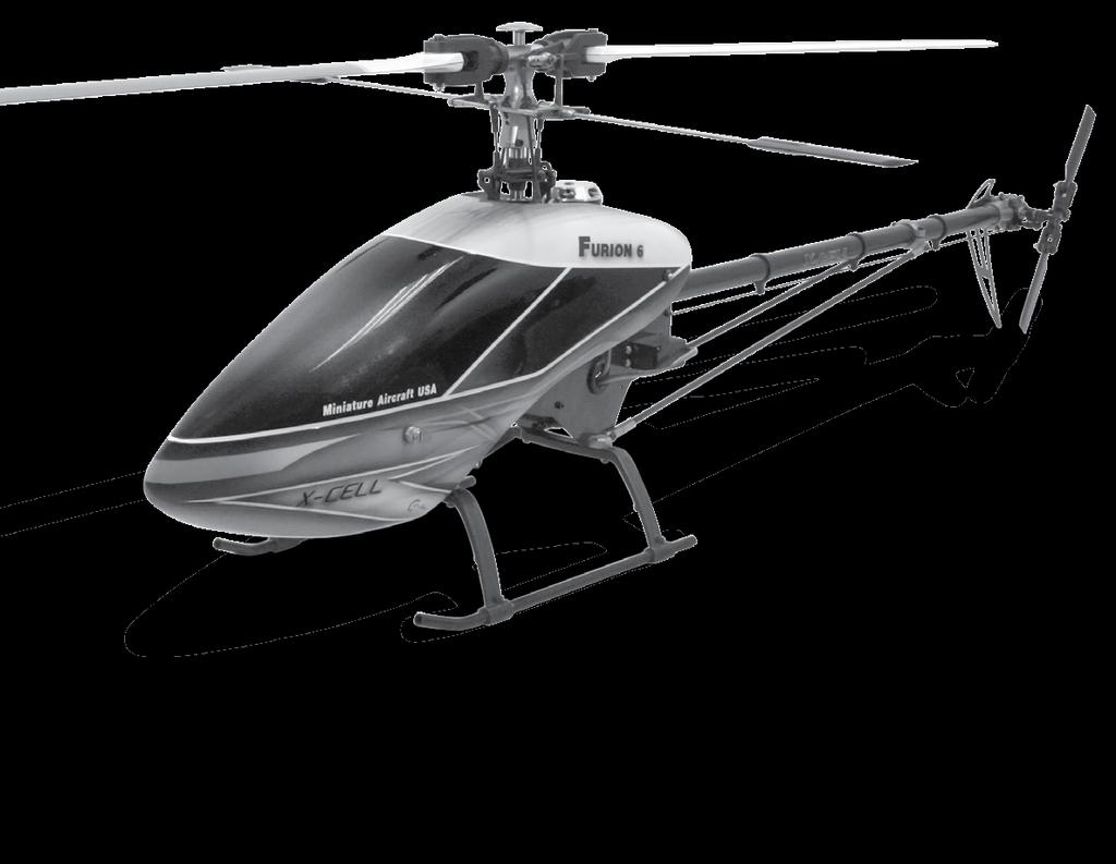
4 Kit Introduction Thank you for purchasing the X-Cell Furion 6 by Miniature Aircraft USA. This model is the culmination of years of designing and manufacturing R/C helicopters. It is designed with the highest standards, and will provide years of enjoyment. Whether this is your first R/C model helicopter or you are an advanced R/C helicopter modeler, the X-Cell Furion 6 is a fantastic choice for a 600 size model. R/C Helicopter Safety A radio controlled model helicopter is not a toy, but rather a technically complex device that must be built and operated with care. It is also a fascinating and challenging part of the R/C sport, the mastery of which is very rewarding. A model helicopter must be built exactly in accordance with the building instructions. The kit manufacturer has spent much time and effort refining his product to make it reliable in operation and easy to build. The essentially bolt together construction can proceed quite rapidly, giving the builder a strong sense of accomplishment that encourages hasty progress from one construction phase to the next, so that the completed model can be more quickly seen and enjoyed. It is essential to recognize and guard against this tendency. Follow building instructions exactly. Vibration and stress levels are high and all fasteners and attachments must be secure for safe operation. Note that this is the first use of the word SAFETY in these comments. Previously the kit manufacturer s efforts to ensure reliable operation were mentioned. That is ALL that he can do. Safe operation is the responsibility of the builder/flyer and starts with careful construction and continues with selection and installation of reliable radio equipment and engine. The need for safety is nowhere greater than at the flying field. A number of guidelines for safe flight have been developed by experienced flyers and are set down here. It is urged that they be read, understood and followed. Warning! Risk of death or serious injury Remote Control ( R/C ) Helicopters can be dangerous. Inexperienced pilots of R/C Helicopters should be trained and supervised by experienced operators. All operators should use safety glasses and other appropriate safety equipment, and exercise necessary precautions when fueling, repairing, maintaining, flying and storing R/C Helicopters, and when using or storing R/C Helicopter accessories, equipment, fuels, and related materials. R/C Helicopters should be used only in open areas free of obstacles, and far enough from people to minimize the possibility of injury from the helicopter or any of its components falling or flying in unexpected directions. This helicopter is not a toy, but a complex flying machine that must be assembled with care by a responsible individual. Failure to exert care in assembly, or radio or accessory installation, may result in a model incapable of safe flight or ground operation. Rotating components are an ever present danger and source of injury to operators and spectators. Since the manufacturer and his agents have no control over the proper assembly and operation of his products, no responsibility or liability can be assumed for their use. General Guidelines for Safe R/C Helicopter Flight Fly only at approved flying fields and obey field regulations. Follow frequency control procedures. Interference can be dangerous to all. Know your radio. Check all transmitter functions before each flight. Be aware that rotating blades are very dangerous and can cause serious injury. Never fly near or above spectators or other modelers. If you re a beginner, get help trimming the model first and flight training later. Don t track the main blades by holding the tail boom. This is a temptation to builders who cannot hover yet and is very dangerous. Follow all recommended maintenance procedures for model, radio and engine. 4
5 Academy of Model Aeronautics Miniature Aircraft USA highly recommends joining the Academy of Model Aeronautics (AMA). AMA is the Academy of Model Aeronautics. AMA is the world s largest model aviation association, representing a membership of more than 150,000 from every walk of life, income level and age group. AMA is a self-supporting, non-profit organization whose purpose is to promote development of model aviation as a recognized sport and worthwhile recreation activity. AMA is an organization open to anyone interested in model aviation. AMA is the official national body for model aviation in the United States. AMA sanctions more than a thousand model competitions throughout the country each year, and certifies official model flying records on a national and international level. AMA is the organizer of the annual National Aeromodeling Championships, the world s largest model airplane competition. AMA is the chartering organization for more than 2,500 model airplane clubs across the country. AMA offers its chartered clubs official contest sanction, insurance, and assistance in getting and keeping flying sites. AMA is the voice of its membership, providing liaison with the Federal Aviation Administration, the Federal Communications Commission, and other government agencies through our national headquarters in Muncie, Indiana. AMA also works with local governments, zoning boards, and parks departments to promote the interests of local chartered clubs. AMA is an associate member of the National Aeronautic Association. Through NAA, AMA is recognized by the Fédération Aéronautique Internationale (FAI), the world governing body of all aviation activity, as the only organization which may direct U.S. participation in international aeromodeling activities. For more detailed information, contact the Academy of Model Aeronautics 5161 E. Memorial Drive, Muncie, Indiana, or telephone (800) You may also visit the AMA website at 5
6 Kit Assembly Your Furion 6 kit will require a number of different supplies and tools to ensure the best final result. They are as follows: Required Lubricants and Compounds: 1. Medium Strength Thread Locking Compound - X-Cell Super Lock Blue (MA ) 2. Tri-Flow Oil (MA ) 3. Tri-Flow Synthetic Grease (MA ) 4. Medium Cyanoacrylate (CA) 5. Retaining Compound - X-Cell Super Lock Green (MA ) Required Tools: 1. m4 Nut Driver 2. m5 Nut Driver 3. m5.5 Nut Driver 4. m7 Nut Driver mm Allen Driver mm Allen Driver mm Allen Driver mm Allen Driver 9. Needle Nose Pliers 10. Phillips Screwdriver #1 11. Flat Screwdriver 2.5mm 12. Razor Knife (X-acto) 13. Snap Ring Pliers Optional Tools: 1. Swashplate Leveling Tool (MA ) 2. Pitch Gauge (MA ) 3. Flybar Alignment Gauge (MA ) 5. Furion 6 Head Set Up Tool (MA ) 6. Optical Heli Tachometer (MA ) Other required components: The X-Cell Furion 6 is an airframe kit. To complete the model, several other items are required but are not included with the kit. There are many choices for these other required components, and any competent hobby retailer with R/C helicopter experience will be happy to make suggestions. You will need: 1. Brushless electric motor (6S KV Range or 10S KV Range ). Motor shaft dimension 6mm x 30/32mm 2. Electronic Speed Control (ECS) suitable for use in R/C helicopters 3. Lithium Polymer Batteries: 6 cell 5000mah or 10 cell (2 x 5S) mah setups are recommended 4. Cyclic servos (Miniature Aircraft USA recommends high quality cyclic servos with no less than 80 oz. in. of torque.) 5. R/C helicopter gyro (Miniature Aircraft USA recommends a heading hold style gyro) 6. Rudder servo suitable for use with the gyro you choose. 7. R/C helicopter transmitter and receiver with at least 6 channels, and eccpm capabilities. 8. Receiver battery pack, or BEC 6
7 Important Assembly Tips - Please Read Follow the instructions. The methods of construction documented in this manual have been proven to work. Do not rush the build of your model! You have purchased a world class model helicopter kit, take your time and realize that the final result is now up to you. Take the time to fully understand each step, if you are unsure please contact Miniature Aircraft USA. Follow the order of assembly. The instructions have been organized into major sections and have been written in such a way that each step builds upon the work done in the previous step. Changing the order of assembly may result in unnecessary steps. Clean all metal parts: All of the steel parts in this kit are coated with a lubricant to prevent them from rusting. This coating can interfere with the adhesives and thread locks needed for assembly. Use a solvent such as alcohol or acetone to clean the various metal parts, especially threads. Use thread lock as indicated. Generally, any bolt or screw that threads into a metal part requires thread lock. Model helicopters are subject to vibration and failing to use thread lock on any non-locking assembly may result in a part becoming loose or falling off. 7
8 Kit Contents Please take some time to familiarize yourself with the contents of the kit. The Furion 6 kit has been broken down into four bags. Each bag contains parts and hardware. The hardware for each bag will be used only for that bag. There will be no left over parts after each bag is assembled. Bag Part No. Part Description Qty 1-A C/F Right Main Frame w/pems 1 1-A C/F Left Main Frame w/pems 1 1-A G-10 Antirotation Guide w/pems 1 1-A C/F Left Servo Mount A C/F Right Servo Mount A C/F Gyro Plate A C/F Electronic Plate A C/F Boom Mount Brace A C/F Battery Plate A C/F Canopy Break-away Mounts Bag Part No. Part Description Qty 1-Hardware m5 x 5 Socket Set Screw 1 1-Hardware m2.5 x 6 Socket Bolt 1 1-Hardware m3 x 6 Socket Bolt 78 1-Hardware m3 x 12 Tapered Socket Head Bolt 4 1-Hardware 0063 m3 x 10 Socket Bolt 8 1-Hardware m3 x 6 Button Head Socket Bolt 6 1-Hardware 0065 m3 x 12 Socket Bolt 2 1-Hardware 0067 m3 x 14 Socket Bolt 6 1-Hardware m3 x 6 Tapered Socket Head Bolt 2 1-Hardware 0071 m3 x 18 Socket Bolt 4 1-B Corner Block 2 1-B Lower Mainshaft Block w/bearing 1 1-B Aluminum Tray Mounts 4 1-B Frame Spacers 4 1-B Rear Canopy Mounts 2 1-B Front Canopy Mounts 2 1-B Landing Gear Mounting Block 4 1-B Pulley Mount 1 1-B Aluminum Idler Pulleys - Assembled 2 1-B Aluminum Boom Clamps 2 1-B Upper mainshaft Block w/bearing 1 1-B Battery Mount Rails 2 1-B Knurled Thumb Screw 4 1-B /16 Rubber Wire Grommets 3 1-B Lower Motor Bearing Block w/bearing 1 1-C Plastic Struts 2 1-C A Skid Plugs 4 1-C Aluminum Skids 2 1-C C/F Strut Support D Main Shaft Collar 1 1-D Main Shaft 1 1-D T T/R Drive Belt 1 1-D Autorotation Hub 1 1-D T T/R Drive Pulley 1 1-D T Main Gear 1 1-D Motor Mount 1 1-D Tooth Pinion Gear 1 1-D Tooth Pinion Gear 1 1-Hardware 0003 m3 Washer 10 1-Hardware 0019 m3 Locknut 4 1-Hardware 0057 m4 x 4 Socket Set Screw 2 1-Hardware m4 x 6 Socket Set Screw 4 1-Hardware m5 x 8 Dog-Point Socket Set Screw A Aluminum Tail Boom 1 2-A T/R Control Rod 1 2-A Boom Support Assembly 2 2-A m3 x 440 Flybar 1 2-B T Tailrotor Pulley 1 2-B T/R Output Shaft 1 2-B Front Boom Support Spacer 1 2-B Plastic Rudder Pushrod Guides 3 2-B A Upper Rear Boom Support Clamp 1 2-B B Lower Rear Boom Support Clamp 1 2-B Aluminum Transmission Clamp 1 2-B m3 Threaded Bearing Stud 2 2-B Ball Bearing T/R Idler 1 2-B Aluminum Bellcrank Mount 1 2-B C/F Left Tail Plate w/ Bearing 1 2-B C/F Right Tail Plate w/ Bearing 1 2-B C/F Vertical Fin 1 2-C 0133 Ball Link 2 2-C zz Ball Bearing m3 x 7 x C 0361 Control Ball 4 2-C 0445 Plastic T/R Bellcrank 1 2-C x.310 x.003 S/S Shim 2 2-C 0457 F4-10m Thrust Bearing 3 pc. 2 2-C /16 x.182 Brass Spacer 1 2-C Plastic T/R Blade Mounts 2 2-C m5 x 10 x 4 Ball bearing 2 2-C Steel Tail Hub 1 2-C T/R Pitch Slider Assembly 1 2-C Plastic T/R Blades 2 2-C Delrin T/R Blade Spacers 4 2-Hardware 0001 m2 Washer 2 2-Hardware m4 External Serrated Lock-Washer 4 2-Hardware 0017 m3 Hex Nut 1
9 Kit Contents Bag Part No. Part Description Qty 2-Hardware 0019 m3 Locknut 2 2-Hardware 0021 m4 Locknut 2 2-Hardware m2 x 8 Socket Bolt 4 2-Hardware 0053 m3 x 5 Socket Set Screw 1 2-Hardware 0056 m3 x 5 Dog-Point Socket Set Screw 3 2-Hardware m3 x 6 Socket Bolt 9 2-Hardware 0065 m3 x 12 Socket Bolt 3 2-Hardware m4 x 10 Button Head Socket Bolt 4 2-Hardware 0091 m3 x 16 Phillips Bolt 1 2-Hardware 0097 m3 x 22 Phillips Bolt 2 3-A 0107 m3 x 6 Threaded Control ball 3 3-A 0109 m3 x 8 Threaded Control Ball 4 3-A 0112 m3 x 9.4 Threaded Ball 2 3-A 0159 m3 x 7 x 3 Ball Bearing 4 3-A 0217 Swashplate 1 3-A 0219 Plastic Washout Hub 1 3-A 0221 Plastic Washout Arms 2 3-A Brass Spacer 2 3-A 0869 Plastic Washout Link 2 3-A Swashplate Guide Pin 1 3-A m2 x.584 Washout Pivot Pins 2 3-B 0103 m2 x 5 Threaded Control Ball 4 3-B 0133 Plastic Ball Links 6 3-B 0337 m2 x 30 Threaded Control Rod 3 3-B Knurled Canopy Knob 2 3-B C/F Servo Arm Alignment Gauge 1 3-B Plastic Servo Blocks 2 3-B G-10 Servo Retainers 1 3-B Carbon Cyclic Servo Spacers 1 3-B /2 x 15 Back to Back Velcro 1 3-B /4 x 25 Back to Back Velcro 1 3-B /4 Adhesive Back Hook & Loop Velcro 1 3-B Rear Canopy Grommets 2 3-B Front Canopy Grommets 2 3-Hardware 0015 m2 Hex Nut 4 3-Hardware 0038 M2.5 x 10 Phillips Bolt 4 3-Hardware m2.5 x 14 Phillips Bolt 8 3-Hardware m2.5 x 16 Phillips Bolt 4 3-Hardware 0051 m3 x 3 Socket set Screw 3 3-Hardware 0071 m3 x 18 Socket Head Bolt 2 3-Hardware 0097 m3 x 22 Phillips Bolt 2 3-Hardware m1.5 E-Clips 2 Bag Part No. Part Description Qty 4-A Flybar Control Bar 2 4-A Flybar Paddles 2 4-A Flybar Control Arm with Base 2 4-A Head Button 1 4-B 0109 m3 x 8 Threaded Control Ball 2 4-B 0112 m3 x 9.5 Threaded Control Ball 2 4-B Plastic Main Blade Grip w / 0319 Brg. 2 4-B D Bell Mixer Assembly 2 4-C Grey Ball Links 8 4-C 0319 m8 x 16 x 5 Ball Bearing 2 4-C 0324 m10.75 x 16 x 1 Washer 2 4-C 0331 m8 x 14 x.5 Shim Washer 4 4-C 0332 m8 x 14 x 1 Shim Washer 2 4-C pc. Thrust Bearing 2 4-C D Head Dampener O-Rings 4 4-C m8 Retaining Clips 2 4-C Clip Application Tool 1 4-C C/F Washer m5 x C m3 x 86 Threaded Control Rod 2 4-C Head Axel 8mm 1 4-C m3 x 16 Dowel Pin 1 4-C Nylon Blade Washers 4 4-Hardware 0021 m4 Locknut 2 4-Hardware m3 x 16 Socket Set Screw 2 4-Hardware 0057 m4 x 4 Socket Set Screw 3 4-Hardware 0063 m3 x 10 Socket Bolt 2 4-Hardware m3 x 6 Button Head Socket Bolt 4 4-Hardware 0067 m3 x 14 Socket bolt 1 4-Hardware 0082 m4 x 38 Socket bolt 2 4-Hardware 0086 m5 x 12 Flanged Socket bolt 2 4-Hardware 0091 m3 x 16 Phillips Bolt 2 BOX Canopy 1 BOX Instruction Set 1 BOX Towel 1 4-A 0112 m3 x 9.5 Threaded Control Ball 2 4-A 0133 Ball Link 4 4-A 0337 m2 x 30 Threaded Control Rod 2 4-A Head Block Assembly 1 9


10 Bag 1 Hardware Bag 1 Parts Pre-Assembled from Factory Lower Main Shaft Bearing Block Upper Main Shaft Bearing Block Autorotation Hub Lower Motor Bearing Block Aluminum Idler Pulleys 10
11 Getting Started Bag 1 Locate bag 1, and the hardware for bag 1. Please take the time to identify the hardware for this bag. Please note that the use of medium thread locking compound is always required when a part is threaded into metal. There may be times when the use of thread locking compound will not be used until a later point in the build Apply a small amount of medium thread lock when threading into metal parts X X Illustration 1a In this step, you will attach parts to the right main frame side. Refer to Illustration 1a for this step. Locate parts bags 1a, 1b, 1c, and 1d, and hardware bag 1. Locate the MA right side main frame from bag 1a. Use 4 MA m3x6 socket head bolts to attach the two MA landing gear mounting blocks from bag 1b to the outside of the frame as shown. Use 4 MA m3x6 socket head bolts to attach 3 MA frame spacers from bag 1b as shown. Use 1 MA m3x6 socket head bolt and an MA0003 m3 washer to attach the front canopy mount from bag 1b, and 1 MA m3x6 socket bolt to attach the MA rear canopy mount from bag 1b to each of the MA canopy breakaway mounts from bag 1a as shown. Use 1 MA m3x6 socket bolt to attach the front canopy mount assembly to the MA right side main frame, and use 1 MA m3x6 socket bolt to attach the rear canopy mount assembly to the MA right side main frame. The rear canopy mount assembly is attached to the right side main frame assembly using an MA frame spacer from bag 1b. Attach the front canopy mount assembly to the right main frame side into the PEM nut. A PEM nut has been installed at the factory for this bolt to attach to. Insert the MA /16 rubber wire grommet from bag 1b into the hole in the frame as shown. 11
12 Apply a small amount of medium thread lock when threading into metal parts X X Illustration 1b In this step, you will continue to attach parts to the right main frame side. Refer to Illustration 1b for this step. Use Locate 1 MA battery mount rail from bag 1b and thread in 1 MA0065 m3x12 socket bolt into the front of the MA battery mount rail, and thread in 1 MA0067 m3x14 socket bolt into the rear of the MA battery mount rail as shown. Use 3 MA m3x6 button head socket bolts and attach the battery mount rail assembly to the MA right side main frame as shown. Use 4 MA m3x6 socket bolts to attach the MA upper main shaft bearing block from bag 1b to the MA right side main frame as shown. At this point, leave the MA m3x6 socket bolts slightly loose, and DO NOT use thread locking compound. These will be thread locked and tightened at a later point in the build. Use 2 MA m3x6 socket bolts to attach the MA lower main shaft bearing block from bag 1b to the MA right side main frame as shown. At this point, leave the MA m3x6 socket bolts slightly loose and DO NOT use thread locking compound. These will be thread locked and tightened at a later point in the build. Use 2 MA m3x6 socket bolts and attach the MA lower motor bearing block from bag 1c as shown. At this point, leave the MA m3x6 socket bolts slightly loose and DO NOT use thread locking compound. These will be thread locked and tightened at a later point in the build. Use 4 MA m3x6 socket bolts and attach the two MA boom clamps from bag 1b to the right main frame assembly. Tighten the lower bolts, but leave the upper bolts slightly loose, and DO NOT use thread locking compound at this time. These will be thread locked and tightened at a later point in the build. Use 2 MA m3x6 socket bolts, and 2 MA0067 m3x14 socket bolts to attach the MA boom mount brace from bag 1a to the two MA boom clamps. Do not fully tighten the two MA0067 m3x14 socket bolts, and DO NOT use thread locking compound at this point. These will be thread locked, and tightened at a later point in the build. 12
13 Apply a small amount of medium thread lock when threading into metal parts 2X X Illustration 1c In this step, you will continue to attach parts to the right main frame side. Refer to Illustration 1c for this step. Use two MA m3x6 socket bolts to attach the MA tray mount from bag 1b to the top of the MA c/f gyro plate from bag 1a as shown. Note the orientation of the MA in image 1c. Use two MA m3x6 tapered head socket bolts to attach an MA tray mount from bag 1b to the bottom of the MA c/f gyro plate from bag 1a as shown. Use two MA m3x6 socket bolts to attach the gyro plate assembly to the right side frame assembly as shown. Use 4 MA m3x6 socket bolts to attach two MA tray mounts from bag 1b to the MA electronics plate as shown. Use two MA m3x6 socket bolts to attach the electronics plate assembly to the right main frame side as shown. Note the orientation of the electronics plate assembly in Illustration 1c. 13

14 Apply a small amount of medium thread lock when threading into metal parts X Illustration 1d In this step, you will assemble and install the idler pulley assembly. Refer to Illustration 1d for this step. Use two MA0067 m3x14 socket bolts to attach the MA aluminum idler pulleys from bag 1b to the MA aluminum pulley mount from bag 1b as shown. Note the orientation of the pulley mount assembly as shown. Use two MA m3x6 socket bolts to attach the aluminum idler pulley assembly to the right main frame assembly as shown Illustration 1e In this step, you will attach parts to the left main frame side. Refer to Illustration 1e for this step. Use four MA m3x6 socket bolts to attach two MA landing gear mounting blocks from bag 1b to the outside of the MA left side main frame as shown. Use Locate 1 MA battery mount rail from bag 1b and thread in 1 MA0065 m3x12 socket bolt into the front of the MA battery mount rail, and thread in 1 MA0067 m3x14 socket bolt into the rear of the MA battery mount rail as shown. Use 3 MA m3x6 button head socket bolts and attach the battery mount rail assembly to the MA right side main frame as shown

15 Apply a small amount of medium thread lock when threading into metal parts 22x Illustration 1f In this step, you will continue to attach parts to the left main frame side, and join the left main frame side to the right main frame side. Refer to Illustration 1f for this step. Use 1 MA m3x6 socket head bolt and an MA0003 m3 washer to attach the front canopy mount from bag 1b, and 1 MA m3x6 socket bolt to attach the MA rear canopy mount from bag 1b to each of the MA canopy breakaway mounts from bag 1a as shown. Use 1 MA m3x6 socket bolt to attach the front canopy mount assembly to the MA left side main frame. A PEM nut has been installed at the factory for this bolt to attach to. Insert two MA /16 rubber wire grommets into the left side frame assembly as shown. Use 22 MA m3x6 socket bolts to attach the left side main frame assembly to the right side main frame assembly. Please note: Do not apply thread locking compound to the MA m3x6 socket bolts going into the upper and lower bearing block or the lower motor bearing block. These will be thread locked and tightened at a later point in the build. Use an MA m3x6 socket bolt to attach the rear canopy mount assembly. This socket bolt will thread into the frame spacer, as shown. 15
16 Apply a small amount of medium thread lock when threading into metal parts X CA CA A x CA Illustration 1g A CA In this step you will attach the battery tray, and landing gear assembly to the main frame assembly. Refer to Illustration 1g for this step. Use four MA0071 m3x18 socket bolts, and four MA0003 m3 washers to attach the two MA c/f strut supports from bag 1d and MA landing gear from bag 1d to the bottom of the MA landing gear mounting blocks. Insert the two MA aluminum skids from bag 1d through the MA landing gear, and secure with four MA m4x6 socket set screws. Use a small amount of CA (cyanoacrylate) and insert the MA127-54a skid plugs from bag 1d into the ends of the skids. 16

17 Apply a small amount of medium thread lock when threading into metal parts X Illustration 1h In this step you will attach the left and right servo mount assemblies to the main frame assembly. Refer to Illustration 1h for this step. Use two MA m3x6 socket bolts to attach an MA corner block from bag 1b to the MA c/f left servo mount, and use two MA m3x6 socket bolts to attach an MA corner block from bag 1b to the MA c/f right servo mount as shown. Use four MA m3x6 socket bolts to attach the right and left servo mount assemblies to the inside of the main frame assembly as shown. 17

18 Note the orientation of drive belt in between the two pulleys BELT Illustration 1i In this step you will install the tail rotor drive pulley into the main frame assembly. Refer to Illustration 1i for this step. Insert the MA t/r drive belt from bag 1c through the aluminum boom clamps, and between the aluminum idler pulleys. Pull a loop of the belt out the right frame side, and position the belt around the MA tooth t/r pulley from bag 1c as shown. 18


19 Apply a small amount of medium thread lock when threading into metal parts x Illustration 1j In this step you will assemble and install the main shaft the main gear/auto-rotation hub assembly. Refer to Illustration 1j for this step. Slide the MA main shaft from bag 1c down through the upper and lower main shaft bearing blocks. While the main shaft is inserted in the bearing blocks, apply thread locking compound to and tighten the MA socket bolts that were left loose from a previous step. As the MA socket bolts are being tightened, ensure that the main shaft continues to spin freely in the bearing blocks. After the bearing blocks are securely attached, remove the MA main shaft and set it aside. Use four MA m3x12 tapered head socket bolts, and four MA0019 m3 lock nuts to attach the MA auto rotation hub from bag 1c to the MA machined main gear. Apply thread lock to, and thread in the MA m2.5x6 socket bolt into the MA main shaft collar from bag 1c. Place the tail rotor pulley, main gear/autorotation assembly, and main shaft collar into the main frame assembly, and insert the main shaft down through the upper bearing block bearing, through the tail rotor pulley, main shaft collar, and main gear/autorotation assembly and into the lower bearing block bearing. 19

20 Apply a small amount of medium thread lock when threading into metal parts Illustration 1k In this step you will continue to install the main shaft into the main frame assembly. Refer to Illustration 1k for this step. Use the MA m5x8 dog-point set screw, and the MA m5x5 set screw to fix the MA tooth t/r pulley to the main shaft. Note that there is a dimple in the main shaft. The MA m5x8 dog-point set screw should protrude through the MA tooth t/r pulley into the dimple. The MA m5x5 set screw will simply tighten against the main shaft. 20
21 Apply a small amount of medium thread lock when threading into metal parts MOTOR OR X X Illustration 1l In this step you will install the pinion gear onto your motor, and prepare the motor for installation into the main frame assembly. Refer to Illustration 1l for this step. Prepare your motor for installation by soldering connectors if required. Use an two MA0057 m4x4 set screws and attach either the MA tooth pinion gear, or the MA tooth pinion gear to the motor shaft. Note that the shaft of the motor should protrude beyond the pinion by approximately 6mm. Use four MA0063 m3x10 socket bolts to attach the MA motor mount from bag 1c to the motor as shown. 21

22 Apply a small amount of medium thread lock when threading into metal parts X X X X Illustration 1m In this step you will install the motor and motor mount into the main frame assembly. Refer to Illustration 1m for this step. Use four MA0063 m3x10 socket bolts, and four MA0003 m3 washers and install the motor into the main frame assembly. Ensure that the motor shaft is inserted into the bearing of the lower motor bearing block, and that the gear mesh is set correctly. We recommend only a tiny amount of backlash when setting the gear mesh. A piece of notebook paper inserted between the gears, and then pushing the motor, and lower motor bearing block towards the main gear is the recommend procedure to set the gear mesh. Apply thread locking compound now to the four MA socket bolts, and tighten. 22

23 Bag 1 Completed Assembly 23
24 Bags 2 Hardware Bags 2 Parts Pre-Assembled from Factory X X Only one side shown Boom Support Assembly Tail Rotor Idler Tail Rotor Pitch Slider Left Shown Right Tail Plate Assembly 24

25 Bags 2 Locate bag 2, and the hardware for bag 2. Please take the time to identify the hardware for this bag. Please note that the use of medium thread locking compound is always required when a part is threaded into metal. There may be times when the use of thread locking compound will not be used until a later point in the build. Masking Tape Front of tailboom notch is at the top Illustration 2a Notch at top of tailboom Illustration 2b In this step, you will prepare the tail rotor drive belt for installation. Refer to Illustration 2a for this step. Insert the t/r drive belt through the MA tail boom from bag 2a as shown. We have found that using a small amount of masking tape wrapped around the belt makes it much easier to get the t/r belt through the tail boom. The t/r drive belt must be inserted through the tail boom with a counter-clockwise ¼ twist (as viewed from behind the model.) In this step, you will insert the tail boom into the main frame assembly. Refer to Illustration 2b for this step. Insert the tail boom into the boom clamps as shown. There is a notch in the tail boom for proper alignment. 25
26 X Tailrotor Drive Belt Illustration 2c In this step you will begin to attach parts to the tail boom. Refer to Illustration 2c for this step. Slide three MA plastic rudder pushrod guides from bag 2b onto the tail boom. There are three dimples on each of the MA plastic rudder pushrod guides, and the dimple side goes on first. They are a snug fit on the boom and ideally they will be spaced evenly. Slide on the MA aluminum transmission clamp from bag 2b as shown. 26
27 Apply a small amount of medium thread lock when threading into metal parts 3X X Illustration 2d In this step, you will assemble and attach tail rotor parts to the tail boom. Refer to Illustration 2d for this step. Use the MA0056 m3 x 5 dog point set screw, and the MA0053 m3 x 5 socket set screw to attach the MA tooth tail rotor pulley from bag 2b to the MA t/r output shaft from bag 2b. On one end of the MA t/r shaft there is two dimples and on the other end there is only one dimple. The MA tooth tail rotor pulley gets attached to the end of the shaft with only one dimple. The MA0056 m3 x 5 dog point set screw must protrude into this dimple. The MA0053 m3 x 5 socket set screw simply tightens against the tail rotor shaft. Use two MA m3 x 6 socket bolts and attach the MA right t/r plate from bag 2b to the MA aluminum transmission clamp. Thread a MA threaded bearing stud from bag 2b into the right and left side tail plates. Remove the masking tape from the t/r belt and insert the t/r shaft assembly into the right side tail plate as shown. Slide the MA left side tail plate from bag 2b onto the t/r shaft, and use two MA m3 x 6 socket bolts to attach the left side tail plate to the MA aluminum transmission clamp. Use two MA m3 x6 socket bolts to attach the MA c/f tail fin from bag 2b to the MA aluminum transmission clamp as shown. Note that these two bolts should extend into the two alignment holes in the tail boom. Use two MA m3x6 socket bolts, and attach the MA aluminum bell crank mount to the right and left side plates. Use a MA0065 m3x12 socket bolt inserted from the left (as viewed from behind the model) and tighten) to secure the aluminum transmission clamp to the tail boom. 27
28 Apply a small amount of medium thread lock when threading into metal parts a B Illustration 2e In this step, you will install the boom support assemblies. Refer to Illustration 2e for this step. Use two MA button head socket bolts, two MA external serrated lock washers and the MA front boom support spacer from bag 2b to install the MA boom support assemblies from bag 2a to the main frame assembly as shown. (Notice that the aluminum boom support ends have a dimple on one side. The dimple indicates a slight angle built in to this part. On the Boom support assembly side that attaches to the main frame, the dimple will be facing in.) For added security of this part, we recommend using a green thread locking compound such as MA super lock-green on the MA socket bolts. Pull back on the boom to tighten the tail belt, apply thread lock now and tighten the MA0067 m3x14 socket bolts that were left loose from step 1e. The belt should be moderately tight. It is very important to take great care to not over tighten the MA0067 m3x14 socket bolts. Doing so will result in the aluminum tail boom being crushed. Apply thread lock to and tighten the MA m3x6 socket bolts on Install the MA (a and b) onto the tail boom, and attach the boom support assemblies using two MA button head bolts, and two MA external serrated lock washers per side. Again, the use of green thread locking compound is recommended. It is very important to take care to not over-tighten the MA Doing so will result in the aluminum tail boom being crushed. 28
29 Apply a small amount of medium thread lock when threading into metal parts Illustration 2f In this step you will continue to assemble the tail rotor pitch assembly. Refer to IIllustration 2f for this step. Use an MA m2x8 socket bolt to attach the MA0361 control ball from bag 2c to the MA0445 plastic t/r bell crank from bag 2c as shown. Insert an MA0159 m3x7x3 ball bearing from bag 2c, an MA /16 x.182 brass spacer from bag 2c, and one more MA0159 m3x7x3 ball bearing from bag 2c into the MA0445 plastic t/r bell crank from bag 2c as shown. Use an MA m2x8 socket bolt to attach the MA0361 control ball from bag 2c to the MA t/r pitch slider assembly from bag 2c as shown. Slide the MA t/r pitch slider assembly onto the tail shaft. Insert the MA0091 m3 x 16 phillips bolt into the MA0445 plastic t/r bell crank. Attach the t/r bell crank to the aluminum bell crank mount, making sure that the control ball on the pitch slider assembly is engaging the cup on the plastic t/r bell crank, and thread on an MA0017 m3 hex nut onto the threads as they protrude through the bell crank mount. 29
30 Apply a small amount of medium thread lock when threading into metal parts CA CA Large I.D. Green Tread Lock 0021 SMALL I.D. Illustration 2g In this step you will assemble the tail rotor blade mounts. Refer to Illustration 2g for this step. Use an MA m2 x 8 socket bolt, and an MA0001 m2 washer to attach the MA0361 control ball from bag 2c to each of the MA plastic t/r blade mount from bag 2c. Make sure you use the hole that is closest to the flat side of the arm on the MA plastic t/r blade mount for this application. Insert an MA m5 x 10 x 4 ball bearing from bag 2c into each of the plastic t/r blade mounts. Grease the center ball cage of the MA0457 thrust bearing from bag 2c. We recommend using MA tri-flow synthetic grease. Insert the MA0457 thrust bearing into the plastic t/r blade mounts as shown. Note that the outer race from the MA0457 thrust bearing with the larger inner diameter (I.D.) should be installed first, then the center ball cage, and then outer race with the smaller inner diameter (I.D.) installed, followed by the MA x.310 x.003 stainless steel shim from bag 2c. Slide the plastic t/r blade mounts onto the MA steel tail hub from bag 2c. Use a small amount of green thread locking compound on the threads of the MA0021 lock nut and install the nut on the threads of the t/r hub using a 7mm nut driver (A Mavrikk 7mm nut driver, or Wiha 265 nut driver works well for this. You will not be able to use a socket) Tighten the MA0021 lock nut until a slight resistance is felt, and then back off until the plastic t/r blade mounts rotate freely on the hub. 30
31 Apply a small amount of medium thread lock when threading into metal parts X X Note: Two Dimples in the tailshaft for X PAIR X Illustration 2h In this step, you will attach the tail rotor blade mount assembly to the tail boom. Refer to Illustration 2h for this step. Use two MA0056 m3 x 5 dog point set screws to secure the completed t/r assembly onto the t/r shaft. Note the MA0056 m3 x 5 dog point set screws must engage the dimples on the t/r shaft. The tail rotor control links (MA0442 come preassembled on the MA t/r pitch slider assembly) can now be installed onto the control balls of the t/r blade mount assembly as shown. Install the MA t/r blades from bag 2c using the MA t/r blade mount spacers from bag 2c, the MA0097 Phillips bolts and MA0019 lock nuts. Tighten until the plastic t/r blade does not fall under its own weight. Thread one MA0331 ball link from bag2 Slide the MA T/R control rod from bag 2a through all three of the T/R control rod guides. Make sure they are aligned so that there are no bends in the T/R control rod. Thread on the other MA0133 ball link. It is important to align the T/R control rod guides so that they are positioned approximately 152mm from the ball links. Simply position the center T/R control rod guide evenly between the two outer T/R control rod guides. 31

32 Illustration 2i X Thread one MA0331 ball link from bag 2 Slide the MA T/R control rod from bag 2a through all three of the T/R control rod guides. Make sure they are aligned so that there are no bends in the T/R control rod. Thread on the other MA0133 ball link. It is important to align the T/R control rod guides so that they are positioned approximately 152mm from the ball links. Simply position the center T/R control rod guide evenly between the two outer T/R control rod guides. Bag 2 Completed Assembly 32


33 Bags 3 Hardware Bags 3 Locate bag 3, and the hardware for bag 3. Please take the time to identify the hardware for this bag. Please note that the use of medium thread locking compound is always required when a part is threaded into metal. There may be times when the use of thread locking compound will not be used until a later point in the build CA Apply a small amount of medium thread lock when threading into metal parts Finished Washout Unit 2X Illustration 3a x X Inside X Inside X Outside Finished swashplate In this step you will assemble the washout assembly, and swashplate assembly. Refer to Illustration 3a for this step. Install the MA0159 m3 x 7 x 3 ball bearings from bag 3a into the MA0221 washout arms from bag 3a with an MA brass spacer from bag 3a between the bearings as shown. Use a MA m2 x.584 washout pin from bag 3a and attach the washout link to the washout arm. Use an MA m1.5 e-clip from the 3 hardware bag to secure the pin as shown. Install the MA0109 m3 x 8 threaded control ball from bag 3a into each washout arm. Use CA (cyanoacrylate) on the threads. Use an MA0095 m3 x 19 phillips bolt to attach each completed washout arm to the MA0219 washout hub from bag 3a as shown. Install the MA0051 m3 x 3 socket set screws into the MA0217 swashplate. Only tighten a small amount as the swashplate is new. As the bearing wears in the swashplate, these set screws can be tightened to remove excess play in the bearing. Install three MA0107 m3 x 6 threaded control balls into the outside ring of the swashplate as shown. Install the MA swashplate guide pin from bag 3a onto the swashplate as shown. Install two MA0112 m3 x 9.4 threaded control balls from bag 3a into the inner swashplate ring as shown. These should be installed on opposite sides of the inner swashplate ring. Install two MA0109 m3 x 8 threaded control balls into the remaining two holes on the inner swashplate ring as shown. Please note: The washout links snap onto the shorter MA0109 threaded control balls, and in a later step the hiller rod will snap onto the longer MA0112 threaded control ball. 33

34 Apply a small amount of medium thread lock when threading into metal parts or See notation in written text Servo X X Illustration 3b In this step, you will install the right and left cyclic servos. Refer to Illustration 3b for this step. Use the MA m2.5 x 14 phillips bolts, and the MA G-10 servo retainers from bag 3b, (NOTE: depending which servos you choose, you also have the option of using the MA carbon fiber cyclic servo spacer from bag 3b in order to get the servo linkage straight) to mount the right and left cyclic servos to the cyclic servo mount as shown. There are already PEM nuts installed in the cyclic servo mounts for you. These servos should be mounted so that the output shaft is furthest from the swashplate. It is recommended to use the rubber servo grommets and brass servo eyelets when installing the servos into the model. 34

35 Apply a small amount of medium thread lock when threading into metal parts x Elevator Servo x Gyro Mount and Hardware Removed for clarity X Illustration 3c In this step you will install the elevator servo. Refer to Illustration 3c for this step. Use the MA m2.5 x 16 phillips bolt, the MA plastic servo block from bag 3b, and the MA G-10 servo retainers from bag 3b to mount the elevator servo. There are already PEM nuts installed in the frame for you. These servos should be mounted so that the output shaft is closest to the swashplate. It is recommended to use the rubber servo grommets and brass servo eyelets when installing the servos into the model. 35

36 0038 4x 0103 Threaded Ball mm Hex Nut Rudder Servo Illustration 3d In this step, you will install the tail rotor servo. Refer to Illustration 3d for this step. Use the MA0038 m2.5 x 10 phillips bolts to attach the tail rotor servo to the frame as shown. Install the MA0103 m2 x 5 threaded control ball from bag 3b into the tail rotor servo horn 14-15mm from the center of the servo horn, and secure with an MA0015 2mm hex nut. 36

37 Swashplate and washout assembly Note: Servo wheel or arm must be 19.5mm or 20.0mm from spline to threaded ball servo wheel cut to size x X x X to elevator servo Servo Wheel Alignment Tool Illustration 3e In this step you will build and install the cyclic servo linkages and install the servo horns. Refer to Illustration 3e for this step. Install three MA0103 m2 x 5 threaded control balls from bag 3b into the three cyclic servo horns 19.5mm-20mm from the center of the servo horns and secure with MA0015 m2 hex nuts. Use three MA0337 m2 x 30 threaded control rods from bag 3b, and six MA0133 plastic ball links from bag 3b to make the cyclic servo pu shrods. See page 48 for pushrod lengths. 37


38 wide hook and loop Optional 10-S Battery Setup at top and bottom main battery Gyro and tape wide hook and loop adhesive back Hook and Loop Under Main Batteries Illustration 3f Receiver and tape motor wires radio switch esc unit and In this step, you are shown suggested placement of your battery(ies) and electronics. Refer to Illustration 3f for this step. Install the gyro, receiver, battery pack and ESC unit. Suggested placement for these components are shown in illustration 3f. MA wide hook and loop tape, MA narrow hook and loop tape, and MA adhesive back hook and loop tape are supplied in bag 3b to install these components. Final placement for these components is left to the modeler depending on user preference. 38

39 X X X X Illustration 3g In this step, you will install and mount the canopy. Refer to Illustration 3g for this step. Install the MA0071 m3 x 18 socket bolts into the MA knurled canopy knobs to make the canopy knob assembly. Illustration 3g shows the location for the MA rear canopy grommets from bag 3b, and the MA front canopy grommets from bag 3b. It is suggested that a 3mm hold be drilled in the front dimples to test fit the canopy. You can then determine if the rear canopy holes require adjusting placement before opening the hole to the final grommet size. Once the location of the canopy grommet holes has been verified, ream the holes to their final size of for the front, and for the rear. For best results, we suggest using a reamer rather than a drill bit for opening the holes to their final size. 39

40 Bags 4 Hardware Bags 4 Parts Pre-Assembled from Factory Head Block Assembly Main Blade Grips D Bell Mixer Assembly
41 Bag 4 Locate bag 4, and the hardware for bag 4. Please take the time to identify the hardware for this bag. Please note that the use of medium thread locking compound is always required when a part is threaded into metal. There may be times when the use of thread locking compound will not be used until a later point in the build Apply a small amount of medium thread lock when threading into metal parts Snapped in position Illustration 4a 0133 In this step you will begin to build the main rotor head assembly. Refer to Illustration 4a for this step. Assemble the pushrod linkages using the MA0133 plastic ball links from bag 4a, and the MA0337 m2 x 30 threaded control rod. These pushrod linkages should be measured 13.75mm as shown on page 48 Install the pushrods from the previous step onto the MA flybar control bars from bag 4a. Assemble the MA flybar control arms with base from bag 4a onto the MA flybar control bars as shown. Install the two MA0112 m3 x 9.5 threaded control balls from bag 4a into the flybar cross tube as shown. Install the MA head button from bag 4a onto the rotor head assembly using an MA0067 m3 x 14 socket bolt. 41

42 Apply a small amount of medium thread lock when threading into metal parts aggressive location Normal location NOTE: Flat on flybar for set screw Illustration 4b In this step you will install the flybar and paddles. Refer to Illustration 4b for this step. Insert the MA flybar from bag 2a through the flybar control assembly as shown. Use the MA0057 m4 x 4 socket set screws to secure the flybar. Note that there are flat spots on the flybar for this purpose. Install the MA flybar paddles onto the flybar. There are two options for control response. Use the normal location for general and 3d flying, and the aggressive location for extreme 3d flying only. Use of CA (cyanoacrylate) on the threads of the flybar before threading the paddle on is recommended. Thread on the paddles until the threads on the flybar are no longer visible, ensure that the paddles are threaded on the same amount on either side Illustration 4c CA 0109 In this step, you will assemble and attach the bell mixer to the main rotor blade grip. Refer to Illustration 4c for this step. Install an MA0109 m3 x 8 threaded control ball from bag 4b into the short side of each MA D bell mixer assembly from bag 4b as shown. Install an MA0112 m3 x 9.5 threaded control ball from bag 4b into the outside hole of the long side of the MA D bell mixer assembly as shown. Attach the completed bell mixer assembly to the MA plastic main blade grip from bag 4b as shown using the MA0091 m3 x 16 phillips bolt. Use of CA (cyanoacrylate) on the threads of the MA0091 m3 x 16 phillips bolt is recommended
43 groove for one side complete Illustration 4d In this step, you will install the dampers into the rotor head. Refer to Illustration 4d for this step. Install an m8 C-clip into one of the grooves on the MA mm head axle. Make sure that the sharp edge of the c-clip is facing out. From the opposite side, slide on an MA0332 m8 x 14 x 1 shim, an MA0331 m8 x 14 x.5 shim and two MA durometer o ring dampers. Note: Using both MA0332 and MA0331 damping shims will result in extremely stiff damping and may be difficult to install. For most people, you may omit the MA0331 shims and add them at a different time if heavier damping is desired. Insert the head axle with dampers and shim stack through the rotor head. Install the MA durometer o ring dampers, an MA0331 m8 x 14 x.5 shim, an MA0332 m8 x 14 x 1 shim and an MA m8 C-clip (with the sharp side facing out) from bag 4c onto the other side of the head axle. Use the MA C-Clip installation tool from bag 4c and an MA0086 m5x 12 flanged socket bolt to press the C-clip into the groove. After the C-clip snaps into the groove, remove the MA0086 m5 x 12 flanged socket bolt, and the MA C-clip installation tool. 43
44 Apply a small amount of medium thread lock when threading into metal parts Inner Race Illustration 4e Large I.D Small I.D In this step, you will install the completed main rotor grips to the main rotor head. Refer to Illustration 4e for this step. Grease the center ball cage of the MA thrust bearing from bag 4c. We recommend using MA tri-flow synthetic grease. Note that the outer race from the MA thrust bearing with the larger inner diameter (I.D.) should be installed first, then the center ball cage, and then outer race with the smaller inner diameter (I.D.) installed. Insert an MA0319 m8 x 16 x 5 ball bearing from bag 4c, an MA x 16 x 1 washer from bag 4c, an MA thrust bearing from bag 4c, and MA120-7 c/f washer from bag c into the blade grip as shown. Install the MA0331 from bag 4c onto the head axle next to the C-clip, and then slide the completed blade grip assembly onto the head axle as shown. Use an MA0086 m5 x 12 flanged socket bolt to secure the main blade grip assemblies to the rotor head as shown. 44

45 Apply a small amount of medium thread lock when threading into metal parts Flybar rods and links removed for clarity Illustration 4f In this step, you will attach the completed main rotor assembly to the main shaft. Refer to Illustration 4f for this step. Install the rotor head assembly onto the main shaft. Note that there is a 3mm hole in the main shaft. This must be lined up with the hole in the head block. Insert the MA dowel pin from bag 4c into the head, and through the 3mm hole in the main shaft. Thread in an MA0057 m4x4 socket set screw into the head block to capture the MA dowel pin as shown. Thread in the two MA0063 m3 x 10 socket bolts into the head block as shown, when tightened, these socket bolts provide clamping force onto the main shaft. 45

46 X X X X Illustration 4g In this step, you will build the Bell and Hiller linkages. Refer to Illustration 4g for this step. Make two Hiller linkages using MA m3 x 86 threaded control rods from bag 4c, and MA ball links from bag 4c. The lengths of these rods should be made so that 70mm of the control rod is visible as shown on page 48. Install the completed Hiller linkage rods as shown. Make two Bell linkages using MA m3 x 16 socket set screws from hardware bag 4, and MA ball links from bag 4c. The length of these rods should be made so that 0mm of threaded control rod is visible between the ball links as shown on page

47 per side Used only for 12mm blade roots 0021 Illustration 4h In this step you will install the main rotor blades, and main rotor blade spacers. Refer to Illustration 4h for this step. If you choose to install your rotor blades at this point, do so using the MA0082 m4 x 38 socket bolts, and MA0021 m4 lock nuts. If the rotor blades you have chosen have a 12mm root thickness, please use the MA mm main rotor blade mount spacers as shown. If the rotor blades you have chosen have a 14mm root thickness, these spacers will not be used. 47
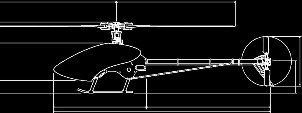
48 Completed Airframe with Electronics and Canopy Installed Control Rod Lengths Bell Mixer to Flybar Servo to Swashplate Washout to Flybar Hiller Swashplate to Bell Mixer 48
49 Basic Model/Radio set up The X-Cell Furion 6 is an eccpm model. This means that the servos that are connected to the swashplate move together to achieve the function requested from the transmitter input. The transmitter mixes the channels required to achieve the correct movement of the swashplate. The X-Cell Furion 6 uses a very simple direct servo to swashplate system that decreases the overall parts count and complexity of the model. The very first thing to do, is center the swashplate servos. Your kit includes a simple pointer tool designed to help you center your servos. Ideally, you rotate the servo horn until the servo is centered, eliminating the use of sub-trim. In your radio For the pitch, aileron, and elevator servos: ATV (servo endpoints) should be at 100%. Set all trims and sub-trims to center or zero. Set an initial linear pitch curve as a straight line (sample points: 0%, 25%, 50%, 75%, and 100%). Make sure there is no mixing enabled for cyclic channels at this point. Center the collective stick and make sure all the cyclic channels are centered. On your model Mount each ball into a servo arm hole approximately 19-20mm from the center of each arm. Slide the servo horns for each channel onto each servo exactly in the middle of its travel. Failing to get them set at center will create interaction in your swash plate travel. If possible, center the horns on the servos without using any sub trim. As a last resort, use the sub trim function to precisely center each servo. Make sure you install hex nuts on the ball retainer bolts using thread locking compound. Make sure you install servo arm retainer screws. In your radio For the rudder servo: Make sure the gyro is in non-heading hold mode. Refer to your gyro manufacturer as to how to enable this. Rudder servo endpoints (ATV) should be at 100%. Make sure there is no mixing enabled for rudder channel at this point (some radios mix throttle to rudder by default). On your model The ball should go into a hole approx 13-15mm from the center of the servo wheel. With your rudder stick centered, rotate the servo wheel until you find a spot that aligns properly and then slide the servo wheel onto the servo exactly in the middle of its travel. Do not use any sub-trim. Now make sure that the T/R bell crank is aligned. The 90 degree pitch slider on the tail case should be in the center of its travel. Adjust the links as necessary to ensure this is correct. Make sure you install hex nuts on the ball retainer bolts using thread lock. Make sure you install servo arm retainer screws. Set up the gyro according to the manufacturers specification in the manual included with the gyro. 49
50 Swashplate eccpm Set Up: Now that you ve built your new Furion 6 helicopter, you have to make the servos work together. The Furion 6 is an eccpm model, and requires a specific radio program for the servos that control the swashplate. eccpm is a mix that is already programmed in your transmitter, you just have to fine tune it to your Furion 6 and here s how: The very first thing you need to do is tell your radio that a 120 degree eccpm mix must be used. All modern transmitters should have 120 degree eccpm built programmed from the factory. Consult the manual that came with your radio! Before you turn on your Transmitter and power up your servos, you need to make sure they are centered. Make sure you use the MA C/F servo alignment tool! With your transmitter and receiver powered on, put collective stick in the exact center with all three swashplate servo horns removed. Then put the horns on so they are 90 degrees to the linkage. This centers the servo horn on the servo and assures that there will be equal travel on either side of the servo s center point. If you find that you cannot get the servo horn exactly at center, you have two choices. You can flip the horn 180 degrees, sometimes the splines will line up perfect, this is the preferred method. You can also use a bit of sub-trim to center the servo. You really want to avoid using subtrim because it makes leveling the swashplate a little more involved. Now you need to make sure that your servos are all working together. What we mean is the three collective servos need to be plugged into the appropriate channels, i.e. the elevator (which is the servo that controls the center ball on the swash) needs to be plugged in to channel 3, the aileron and pitch servo (the ones that control the sides of the swashplate) need to be plugged into channels 2 and 6 (it doesn t matter which channel just either servo, into either 2 or 6 on the RX). IF you use a Futaba or Hitec transmitter, the channel assignments are a little different. For Futaba, Elevator is channel 2, Aileron is Channel 1, and Pitch is Channel is 6. Then, using the servo reverse screen, you need to make sure that the servos are doing the proper function. All the servos need to move up (or down) when the collective stick is moved up or down (it doesn t matter if the collective is reversed, we ll fix that later). If it doesn t, you need to (one at a time) reverse the channels on the servo reverse screen until all the servos move in the same direction when the collective stick is moved. Now the aileron and elevator functions need to be sorted out. When you move the right stick right and left, the swashplate should tilt to the right and left (it doesn t matter if it moves right when you push the stick left, we ll fix that later). Also, when you move the right stick forwards and aft, the elevator should tilt forward or back. (again, it doesn t matter if the FUNCTION is reversed) Now that the SERVOS are all moving in together, we need to be sure that the SWASHPLATE is moving correctly for a given command. Pull up the Swash Mix screen. Futaba calls it Swash AFR There should be 3 functions and they ll look like this: Aileron: 60% Elevator: 60% Pitch: 60% So, if the the swashplate tilts left when you move the cyclic (right) stick TO the right, make the value of 60% for Aileron NEGATIVE or -60%, and likewise for the elevator, so if the swash tilts forward when you pull the cyclic stick BACK, make the value of 60% NEGATIVE or -60% to correct it. The swashplate should move up and down with the collective stick, and if you RAISE the collective stick, the blades should show POSITIVE PITCH. And if you LOWER the collective stick, the blades should show NEGATIVE pitch. IF that function is reversed, again, make the value of 60%, NEGATIVE 60% or -60%. To ensure that your Furion 6 is set up as precise as possible it is very important that you follow the pitch curve set up guide, and you properly level the swashplate. There are several different tools for determining if your swashplate is level. We recommend the MA Swashplate Leveling Tool. Place the swashplate leveler on the swashplate and ensure that it is level. The collective stick should be at the center with zero degrees pitch on the blades. At this same time as described in the pitch curve set up guide, the swashplate should then be in the center of its travel, and the midpoint of the pitch curve should read 50%. If the swashplate is not level, you can use subtrim to level it, but the preferred method would be adjusting the linkages that connect the swashplate to the servos! If you find that you have to use more than a couple of clicks of subtrim on any channel, you should put it back to zero, and adjust mechanically by adjusting the linkages to the swashplate. After the swashplate is perfectly level at center stick, you need to level it at the extreme pitch range, i.e. full positive pitch and full negative pitch. Place the Collective stick at full positive stick with the swash leveling tool attached. If the swashplate is not level, you will use the End Point screen or Travel Adjust screen. For instance, if the swashplate tilts slightly to the right at full positive pitch, then you will need to increase the travel for the servo that controls that swashplate ball. Now put the collective stick at full negative, repeat the same procedure with the end points. You do have to be careful that you don t create any binding at the extremes of the swashplate s travel. 50
51 Pitch Curve Set Up: It is important that you build your model to exactly the way described in this manual. Make sure all your linkage rods are exactly the length determined in the manual included with your helicopter kit. First, go to the pitch curve menu in your radio for Idle up 1, or Stunt mode 1. You ll see numbers, a graph or both. There will generally be 5 points you can adjust. You ll have to imagine the points (1,2,3,4,5) as representing points on the collective stick, where point 1 represents full bottom stick, and 5 represents full top stick. Obviously that makes point 3 center stick and that s where we start. Ensure that point 3 on the pitch curve (center stick) to equal 50% of the swashplate s up and down travel, meaning the in the middle of it s available travel. So, turn on your transmitter, and receiver, flip the flight mode switch to idle-up 1 or Stunt mode, and scroll to the pitch curve menu. Now place the left stick in the center. Use a pitch gauge, (We recommend MA ) ensure that there is 0 degrees pitch on both rotor blades and that the mixing arms, and washout arms are perpendicular to the mainshaft. If any of this is untrue, you ll need to make it so, by adjusting slightly the length of the pushrods. Now that you ve got 0 degrees at center stick, and point 3 on the pitch curve has a value of 50% (don t deviate here!) We can adjust the pitch at full top and bottom collective stick positions. Generally we want to have the same amount of pitch on the bottom stick position as we do on the top stick position in idle up or stunt mode. That means positive 10 degrees on top stick, and negative 10 degrees on bottom stick. (some pilots are now using more pitch 12, 13 or even 14 degrees, but most people find 10 degrees a perfect place to learn 3D flying). With the transmitter still in idle up, or stunt mode place the collective stick at the top of it s travel, and take a reading of the pitch gauge and remember that number. It should be a positive pitch value and 10 degrees is a good place to start. Now place the collective stick at the full bottom of it s travel. It should be a negative pitch value and again -10 degrees is a good place to start. If the value is not close to 10 degrees then making it so is a simple adjustment of the swash mix function in your transmitter. In this menu, swash mix or swash AFR, there are three options. Elevator, Aileron, and Pitch. Adjusting the pitch value, adjusts the total up and down travel of the swashplate. Making the number higher gives you a greater pitch range, and making the number lower gives you a smaller pitch range. If you find that at full top stick, you get a negative pitch value, and at bottom stick you get a positive pitch value, you would go back to that swash mix menu, and make the value the opposite, Meaning if it was 60%, make the number 60%. That will change the direction of the swash travel. Now, You ll notice that your pitch curve isn t really a curve at all, it s a straight line. You can adjust this if you wish by changing points 2 and 4. Right now, point 2 is 25%, and point 4 is 75%. You can change those values and it will affect how jumpy or responsive the collective is. Usually leaving it a straight line is best until you really get the feel for 3D flying. If you re a beginner chances are you ll want to fly your model around in normal mode. Normal mode means that at full bottom stick the engine is at idle and the blades are not turning. You also don t have any need for there to be negative 10 degrees of pitch, usually more like -4 or -5 degrees is best. This can easily be achieved by raising points 1 and 2. Scroll in the transmitter menu to pitch curve for normal mode, and increase point 1 from 0% to about 35%, and then you can usually inhibit point 2, so it makes a straight line from point 1 to point 3, which should still be 50%. The Pitch Curve for throttle should usually look real similar to stunt mode. Throttle hold is generally used for performing autorotations. 51
52 Throttle Curve Set Up: Turn on your transmitter. Scroll to the throttle curve screen and notice that there are points, usually 5, and all have an assignable percentage. For example, point 1 is 0%, and point 5 is 100%. This will be the starting point for normal mode, and will get the model in the air. Once you have this set up in normal mode, you ll have to fly the helicopter to determine whether you need more or less headspeed. This is usually a good starting point for hovering. The method you set up the throttle curve for idle up or stunt mode will vary with personal preference and the model ESC you re using. Some ESC s have a governor mode, and their set up will be specific to the model ESC you re using. It is possible to use a simple v curve for throttle on an electric model. A starting point would be to make point 1, 100%, mid point 65%, and point 5 100%. This way you are asking the ESC to go to full throttle at the extremes of the pitch range, and to cut throttle down to 65% when the blades have 0 degrees of pitch. To complete the set up, you ll need a friend and an Optical Tachometer (we recommend MA Optical Heli Tachometer) to observe the head speed of your helicopter. Make sure to follow the rotor speed recommendations given by the manufacturer of the rotor blades you are using. If the head speed is too low, then increase the value of the mid point of the throttle curve by 5% increments until you get the head speed you desire. Choosing your power system: Outfitting your Furion 6 with a power system is slightly more complex than outfitting a nitro model. The first thing you must decide is whether you want a 6s battery powered model, or a 10s battery powered model. If you are a sport style pilot, the 6s battery power system may be a good option. We found that the Scorpion brand outrunner worked very well. We suggest using the 13 tooth pinion gear included in the kit for this motor. We used a high quality 6s 22.2v 5000mah lithium polymer battery, and a Castle Creations brand ESC in this case we recommend the Castle Creations ICE 100. If you are into hard core 3d flying, or you like BIG POWER, then the 10s battery power system is definitely for you. We found that the Scorpion brand outrunner worked very well. We suggest using the 12 tooth pinion gear included with the kit for this motor. We used TWO high quality 5s 18.5v 5000mah lithium polymer batteries wired in series. The design of the Furion 6 is such that if you want to use the 10s battery power system, you must use two 5s packs in series. We recommend the Castle creations ICE 120 HV, and found it to work very well. Of course these are not the only options available to power your Furion 6, but we spent a lot of time with these products and found them to work very well, be of high quality, and easy to find at many retailers. 52
53 Furion 6 Kit Hardware MA0001 MA0003 MA0007 MA MA MA MA0014F MA0015 MA MA0017 MA0019 MA0021 MA0029 MA0038 MA MA MA0051 MA0053 MA0056 MA0057 M2 Washer M3 Washer-large 6mm Washer M5 x 15 x 0.8 Washer M2.5 PEM Nut M3 PEM Nut Fine Thread M5 Hex Nut M2 Hex Nut M4 External Serrated Lock Washer M3 Hex Nut M3 Locknut M4 Locknut M2.2 x 13 Phillips Self Tapping Screw M2.5 x 10 Phillips Bolt M2.5 x 16 Phillips Bolt M2 x 8 Socket Bolt M3 x 3 Socket Set Screw M3 x 5 Socket Set Screw M3 x 5 Dog-point Socket Set Screw M4 x 4 Socket Set Screw MA MA MA MA MA MA MA0061 MA MA0063 MA MA MA0065 MA0067 MA MA0082 MA0086 MA0091 MA0095 MA0097 MA M4 x 6 Socket Bolt M4 x 16 Socket Set Screw M5 x 8 Dog-point Socket Set Screw M5 x 5 Socket Set Screw M2.5 x 6 Socket Bolt M3 x 6 Socket Bolt M3 x 8 Socket Bolt M3 x 12 Tapered Socket Head Bolt M3 x 10 Socket Bolt M3 x 6 Button Head Socket Bolt M4 x 10 Button Head Socket Bolt M3 x 12 Button Head Socket Bolt M3 x 14 Socket Bolt M4 x 10 Socket Bolt M3 x 38 Socket Bolt M5 x 12 Flanged Socket Bolt M3 x 16 Phillips Bolt M3 x 19 Phillips Bolt M3 x 22 Phillips Bolt M1.5 E-clip Furion 6 Kit Parts MA0103 MA0107 MA0109 MA0112 MA0133 MA MA0159 MA0183 MA0208 MA0214 MA MA0216 MA0217 MA0218 MA0219 MA0221 MA0225 MA0273 MA0283 MA0317 MA0319 MA0324 MA0331 MA0332 MA0337 MA0361 MA0367 MA0390 M2 x 5 Threaded Control Ball M3 x 6 Threaded Control Ball M3 x 8 Threaded Control Ball M3 x 9.4 Threaded Control Ball Ball Link for 2mm Grey Ball Link for 3mm M3 x 7 x 3 Ball Bearing M10 x 19 x 5 Ball Bearing 10mm Torrington Clutch Bearing Upper Swashplate Ring Lower Swashplate Ring M20 x 32 x 7 Ball Bearing Swashplate Heim Ball GE-10C Plastic Washout Hub Plastic Washout Arms M2 x 13.6 Dowel Pin M6 x 10 x.011 Steel Shim Washer M6 x 10 x 3 Flanged Ball Bearing Plastic Main Blade Mount M8 x 16 x 5 Ball Bearing M10.75 x 16 x 1 Washer M8 x 14 x.5 Washer M8 x 14 x 1 Washer M2 x 30 Threaded Control Rod Control Ball M2 x 60 Threaded Control Rod Push-on Wire Retainers 53 MA0435 Brass Slider MA0437 Plastic Control Ring MA0439 M6 x 10 x 2.5 Open Ball Bearing MA0440 Control Yoke MA0442 Pivoting Ball Link MA0443 Push-on Retainer MA x.310 x.003 Stainless Steel Shim MA0445 Plastic T/R Bellcrank MA0457 F4-10 Thrust Bearing 3 Pc MA /16 x.182 Brass Spacer MA Brass Spacer MA Brass Spacer MA Corner Block MA pc Thrust Bearing Main Rotor MA Guide Pins MA D Head Damper O Rings MA M8 Retaining Clips MA Clip Application Tool MA0869 Plastic Washout Link MA Plastic T/R Blade Mount MA Main Shaft Collar MA M6 x 15 x 5 Ball Bearing MA M3 x 7 x 3 Flanged Ball Bearing MA Rubber Grommet Front Canopy MA Rubber Grommet Rear Canopy MA120-7 M5 x 5.5 C/F Washer MA M3 x 86 Threaded Control Rod MA M5 x 10 x 4 Ball Bearing
54 Furion 6 Kit Parts MA M3 x 86 Threaded Control Rod MA M5 x 10 x 4 Ball Bearing MA Canopy Knob MA M3 x.080 Brass Spacer MA Steel T/R Hub MA T T/R Pulley MA T/R Output Shaft MA Plastic Strut MA127-54A Skid Plugs MA Lower Main Shaft Bearing Block w/bearing MA Main Shaft MA T T/R Drive Belt MA Brass Bushing MA Autorotation Hub MA Aluminum Tray Mount MA Frame Spacers MA Front Boom Support Spacer MA Rear Canopy Mount MA Front Canopy Mount MA Landing Gear Mounting Block MA Aluminum Skids MA Pulley Mount MA Aluminum Idler Pulley w/bearing MA M3 x 9 x 4 Ball Bearing MA Aluminum Boom Clamp MA Aluminum Tail Boom MA T/R Control Rod MA Plastic Rudder Pushrod Guides MA C/F Boom Support Tube MA Aluminum Boom Support Ends MA Boom Support Assembly MA Rear Boom Support Clamp MA Aluminum Transmission Clamp MA M3 Threaded Bearing Stud MA T/R Idler Pulley w/bearings MA Aluminum Bellcrank Mount MA T/R Pitch Slider Assembly MA M6 x 1 Shim Washer MA C/F Left Tail Plate w/bearing MA M5 x 13 x 4 Flanged Ball Bearing MA C/F Right Tail Plate w/bearing MA Plastic T/R Blades MA C/F Vertical Fin MA Plastic Servo Blocks MA G-10 Servo Retainers MA C/F Cyclic Servo Spacers MA M2 x.584 Washout Pivot Pins MA Head Block Assembly MA Head Block MA Flybar Pivot Tube MA mm Head Axle MA Main Blade Grip w/ma0319 Bearing MA Flybar Control Bar MA Flybar Paddle MA Flybar Control Arm W/base MA M3 x 440 Flybar MA Head Button MA D Bell Mixer Assembly MA M3 x 16 Dowel Pin MA C/F Right Main Frame w/pems MA C/F Left Main Frame w/pems MA G-10 Antirotation Guide w/pems MA C/F Left Servo Mount MA C/F Right Servo mount MA C/F Gyro Plate MA C/F Electronics Plate MA C/F Boom Mount Brace MA C/F Battery Plate MA C/F Break-Away Mount MA Upper Mainshaft Bearing Block w/bearing MA Battery Mount Rails MA Knurled Thumb Nut MA /16 Rubber Wire Grommet MA T T/R Drive Pulley MA Motor Mount MA M6 x 15 x 5 Flanged Bearing MA Lower Motor Bearing Block MA Tooth Pinion MA Tooth Pinion MA C/F Vertical Fin MA Swashplate Guide Pin MA Painted Furion 6 Canopy MA Instruction Set MA M4 x 9 x 4 Ball Bearing MA ½ x 20 Hook and Loop Tape MA ¾ x 15 Hook and Loop Tape 54
55 Warranty The warranty covers defects in material or workmanship or missing components to the original purchaser for 30 days from the date of purchase. Miniature Aircraft, USA will replace or repair, at our discretion, the defective or missing component. Defective components must be returned to us prior to replacement. Any part, which has been improperly installed, abused, crash damaged or altered by unauthorized agencies, is not covered. Under no circumstances will the buyer be entitled to consequential or incidental damages. The components used in this kit are made from special materials designed for special applications and design strengths. We recommend that all replacement parts be original parts manufactured by Miniature Aircraft, USA, to ensure proper and safe operation of your model. Any part used which was manufactured by any firm other than Miniature Aircraft USA, VOIDS all warranties of this product by Miniature Aircraft USA. 55


56 miniature aircraft usa 2885 Farley Lane Billings, MT 59101, USA Phone: Website:
Assembly instructions
 Assembly instructions Step up to Excellence with X-cell 2 Table of Contents Kit Introduction...4 R/C Helicopter Safety...4 Warning...4 General Guidelines...4 Academy of Model Aeronautics (AMA)...5 Kit
500 scale fuselage Airwolf INSTRUCTION MANUAL. Produced By:
 500 scale fuselage Airwolf INSTRUCTION MANUAL Produced By: 1 TABLE OF CONTENTS Additional items required. Adhesives and building supplies.. Disclaimer Parts sheet.... Initial setup. Installing the mechanics..
Specifications ASSEMBLY INSTRUCTIONS
 ASSEMBLY INSTRUCTIONS Specifications Length : 6 mm Height : 218 mm Main Blade : 325 mm Main Rotor Diameter : 723 mm Tail Rotor Diameter : 150 mm Motor Pinion Gear : 16T (14T) Main Drive Gear : 150T Main
700 scale fuselage MD500 INSTRUCTION MANUAL
 700 scale fuselage MD500 INSTRUCTION MANUAL Produced By: 1 TABLE OF CONTENTS Additional items required. Adhesives and building supplies.. Disclaimer Parts sheet.... Fuselage setup. Installing the mechanics..
450 scale fuselage A109 INSTRUCTION MANUAL. Produced By:
 450 scale fuselage A109 INSTRUCTION MANUAL Produced By: 1 TABLE OF CONTENTS Additional items required. Adhesives and building supplies.. Disclaimer Parts sheet.... Initial setup. Installing the mechanics..
XCell Fury Extreme Assembly Manual
 XCell Fury Extreme Assembly Manual Version 1.0 Created: 11/14/2006 Copyright Miniature Aircraft US For More Information contact: Miniature Aircraft USA 31713 Long Acres Drive Sorrento, FL 32776 USA Phone
Hawk Sport. Quick Build Guide. Century Helicopter Products. Designed and Developed in USA
 Hawk Sport Quick Build Guide This Century HAWK SPORT kit comes in a QUICK BUILD format that has most of the major systems already assembled into sub-assemblies. These are packed seperately into their specific
TABLE OF CONTENTS INTRODUCTION 3 CUSTOMER SERVICE 4 FEATURES 5 FRE-ASSEMBLY INFORMATION 6 REQUIRED TOOLS 7 HARDWARE & OPTIONAL ACCESSORIES 8
 Page 1 of 84 TABLE OF CONTENTS INTRODUCTION 3 CUSTOMER SERVICE 4 FEATURES 5 FRE-ASSEMBLY INFORMATION 6 REQUIRED TOOLS 7 HARDWARE & OPTIONAL ACCESSORIES 8 OTHER HARDWARE & OPTIONAL ACCESSORIES 9 OTHER REQUIREMENTS
8-3 MAIN ROTOR BLADE ATTACHMENT (BLADES NOT INCLUDED)
") 8-3 MAIN ROTOR BLADE ATTACHMENT (BLADES NOT INCLUDED) Two sets required Socket Head Bolt, 4 x 35 mm...2 pcs Hold the 4 mm Lock Nut while tightening using a Wiha 7 mm Nut Driver or equivalent. Lock Nut,
8-3 MAIN ROTOR BLADE ATTACHMENT (BLADES NOT INCLUDED) Two sets required Socket Head Bolt, 4 x 35 mm...2 pcs Hold the 4 mm Lock Nut while tightening using a Wiha 7 mm Nut Driver or equivalent. Lock Nut,
INTRODUCTION 3 CUSTOMER SERVICE 4 FEATURES 5 FRE-ASSEMBLY INFORMATION 6 REQUIRED TOOLS 7 HARDWARE & OPTIONAL ACCESSORIES 8
 Page 1 of 69 TABLE OF CONTENTS INTRODUCTION 3 CUSTOMER SERVICE 4 FEATURES 5 FRE-ASSEMBLY INFORMATION 6 REQUIRED TOOLS 7 HARDWARE & OPTIONAL ACCESSORIES 8 OTHER HARDWARE & OPTIONAL ACCESSORIES 9 OTHER REQUIREMENTS
AVANT Aurora Ultimate 90
 2 AVANT Aurora Ultimate 90 Assembly Manual AVANT Aurora Ultimate 90 Assembly Manual V1.08 LIABILITY DISCLAIMER This kit is for a radio controlled (RC) helicopter. RC Helicopters are not toys. Moving parts
I n s t r u c t i o n M a n u a l. Instruction Manual SPECIFICATION
 I n s t r u c t i o n M a n u a l Instruction Manual SPECIFICATION - Wingspan: 3200mm (125,9 in) - Length: 1650mm (64,9 in) - Flying weight: 3000gr 3200gr - Wing area: 64.5 dm2 - Wing loading: 46g/dm2
Instruction Manual book
 book ITEM CODE:BH 115. SPECIFICATION Wingspan : 6,000 mm 236,22 in. Length : 2,740 mm 107,87 in. Weight : 17.5kg 38.5Lbs. Radio : 08 channels. Servo : 07-08 HS-5685MH(HITEC) Battery : 2 Cells-Li-Po 7.4V
RECOMMENDED MOTOR AND BATTERY SET UP
 SPECIFICATION - Wingspan: 6000mm (236.2 in) - Length: 2873mm (113.1 in) - Flying weight: 14-18 kg - Wing area: 219.4 dm2 - Wing loading: 64g/dm2 - Wing type: HQ airfoils - Covering type: Genuine ORACOVER
INSTRUCTION MANUAL WARRANTY
 INSTRUCTION MANUAL Rotor Diameter: 23 in [588mm] Weight: 20.5 23 oz [580 650 g] Length: 25 in [630mm] Height: 9 in [225mm] Motor: 200W brushless, 28mm diameter Heli-Max guarantees this kit to be free from
ALMOST READY TO FLY. Wing Span in cm. 2
 ASSEMBLY MANUAL ALMOST READY TO FLY MS:X9 Specifications Wing Span --------------------------61.4 in ---------------------------156cm. 2 Wing Area --------------------------606.1 sq.in ------------------
B E L T D R I V E T A I L R O T O R A D A P T E R. DAWSO S APPROACH E GI EERI G Ridgecrest, California
 B E L T D R I V E T A I L R O T O R A D A P T E R DAWSO S Ridgecrest, California 93555 www.approachengineering.com 1.0 Purpose To establish a process that ensures control and standardization in the manufacturing
Instruction Manual book
 book Item code:bh131 SPECIFICATION Wingspan : 3,000 mm 118.1 in. Length : 1,600 mm 62.99 in. Weight : 2.2 kg 4.84 Lbs. Radio : 05 channels. Servo : 06 mini servos. Electric Motor: BOOST 40 Battery : 3celIs
AVANT Aurora Ultimate 90
 2 AVANT Aurora Ultimate 90 Assembly Manual AVANT Aurora Ultimate 90 Assembly Manual V2.00 LIABILITY DISCLAIMER This kit is for a radio controlled (RC) helicopter. RC Helicopters are not toys. Moving parts
51in Aerobatic Series Sukhoi SU-26M Almost-Ready-to-Fly. Instruction Manual. Specifications
 51in Aerobatic Series Sukhoi SU-26M Almost-Ready-to-Fly Instruction Manual Specifications Wingspan: 51.2 in (1300mm) Length: 51.2 in (1300mm) Wing Area: 581 sq in (37.5sq dm) Flying Weight: 3.5 lb (1600g)
Section 13. Tail Rotor Drive. RotorWay International A600 TALON Construction Manual. Section 13. Page A
 RotorWay International Page A Tail Rotor Drive Procedures covered in this section: Install driveshafts and gearboxes; install drive belt and tensioner; fabricate and install tail rotor pitch actuator arms;
INSTRUCTION MANUAL WARRANTY
 INSTRUCTION MANUAL Rotor Diameter: 27.5 in [700mm] Weight: 19 22 oz [580 760g] Length: 25.4 in [645mm] Height: 9 in [225mm] Motor: ElectriFly Ammo 28-45-2700kV (GPMG5215) Heli-Max guarantees this kit to
Instruction Manual book
 Instruction Manual book ITEM CODE:BH118. SPECIFICATION Wingspan : 1,050 mm 41.34 inches. Length : 950mm 37.4 inches. Weight : 1 kg 2.2 lbs. Radio : 04 channels. Servo : 4 mini servos. Motor : KMS 2814/05
AVIATOR 25 ARF Almost Ready-to-Fly
 AVIATOR 25 ARF Almost Ready-to-Fly Instruction Manual Specifications Wingspan: 54.3 in (1380mm) Length: 45.2 in (1150mm) Wing Area: 438 sq in (34sq dm) Flying Weight: 3.8 b (1700g) Dear Customer, Congratulations
Instruction Manual book
 Instruction Manual book Item code:bh133 SPECIFICATION Wingspan : 1,400 mm 55.12 in. Length : 1,350 mm 53.15 in. Weight : 3.7 kg 8.14 Lbs. Radio : 08-09 channels. Servo : 08-09 servos. EDF : Turingy SK3
8mm EPP Acrocub. Instruction Manual. Specifications
 8mm EPP Acrocub Instruction Manual Specifications Wingspan: 34.6 in (880mm) Length: 31.5 in (800mm) Wing Area: 213.9 sq in (13.8sq dm) Flying Weight: Approx. 9oz (270g) Dear Customer, www.valuehobby.com/8mm-epp-acrocub.html
RJS2021 LTO SPORT OVAL RACER LESS ELECTRICS
 RJS2021 LTO SPORT OVAL RACER LESS ELECTRICS THANKS FOR BUYING THE RJ SPEED 1/10 LTO SPORT KIT FOR OVAL RACING. THE ASSEMBLY WILL NOT BE DIFFICULT IF YOU READ THE TEXT, LOOK AT THE PICTURES, AND THE EXPLODED
48in Sbach-342. Instruction Manual. Specifications
 48in Sbach-342 Instruction Manual Specifications Wingspan: 48in (1219mm) Length: 46in (1163mm) Wing Area: 471sq in (30.4sq dm) Flying Weight: 1.8-2.0lb (800-900g) Dear Customer, www.valuehobby.com/48in-s342-arf.html
J & D Machine / Hyperdrive / MSA 3711 Moon Bend Rd. Chapel Hill, TN 37034
 J & D Machine / Hyperdrive / MSA 3711 Moon Bend Rd. Chapel Hill, TN 37034 www.hyperdriveracing.com 1 You now own a state of the art 1/10 scale oval race car. The Hyperdrive Assault has gone through months
Instruction Manual book
 Instruction Manual book ITEM CODE:BH135 SPECIFICATION Wingspan : 4,200mm. 163.35 in. Length : 2,100 mm. 82.68 in. Weight : 7,6 kg. 16.72lbs Radio : 07 channels. Servo : 05 06 standard high torque servos,
Manual GLOGO
 Manual GLOGO 690 www.mikado-heli.de Mikado Model Helicopters GmbH Graf-von-Schwerin-Str. 40 14469 Potsdam Germany phone +49 (0)331 3749-0 fax +49 (0)331 3749-11 www.mikado-heli.de Mikado Model Helicopters
PITTS 12 R/C SPORT-SCALE AIRCRAFT ASSEMBLY AND INSTRUCTION MANUAL. Copyright Century UK Limited 2012
 PITTS 12 R/C SPORT-SCALE AIRCRAFT ASSEMBLY AND INSTRUCTION MANUAL 1 Warning: This radio controlled model is not a toy. It requires skill to fly and is not recommended for use by beginners. It should not
RIGGING THE FLIGHT CONTROLS
 RIGGING THE FLIGHT CONTROLS Rigging refers to the installation and adjustment of the rods that move flight surfaces in response to inputs from the controls of the helicopter. These rods are cut to length,
Twister 3D Storm The Ultimate 3D Electric Helicopter
 The Ultimate 3D Electric Helicopter SPECIFICATIONS Main rotor diameter 720mm Tail rotor diameter..135mm Length..630mm Weight (without receiver & battery)....500g (17.5oz) CONTENTS 1...Assembled helicopter
Sport/Pro HELICOPTER First Edition
 Sport/Pro HELICOPTER First Edition ASSEMBLY AND MAINTENANCE MANUAL WWW.QUICKHELI.COM Page 1 of 60 TABLE OF CONTENTS INTRODUCTION 3 CUSTOMER SERVICE 4 FEATURES 5 PRE-ASSEMBLY INFORMATION 6 REQUIRED TOOLS
Instruction Manual SPECIFICATIONS
 Instruction Manual Hummingbird CP Hummingbird FP SPECIFICATIONS Engineered for ultimate performance. Light weight, durable, powerful design featuring CNC machined anodized aluminum heat sink chassis plate,
96in Super Decathlon ARF
 96in Super Decathlon ARF Instruction Manual Specifications Wingspan: 96in (2438mm) Length: 63.5 in (1614mm) Weight: Approx. 13lbs (6.5kg) 1 Dear Customer, Congratulations on your purchase of Super Decathlon
I/C FLIGHT GUIDELINES
 SPECIFICATION - Wingspan: 3500mm (137.8 in) - Length: 1650mm (64.96 in) - Flying weight: 3700-4000 gr - Wing area: 75 dm2 - Wing loading: 49g/dm2 - Wing type: HQ profile - Covering type: Genuine ORACOVER
40 EP Gee Bee Y Scale ARF V2 Instruction Manual Specs:
 40 EP Gee Bee Y Scale ARF V2 Instruction Manual Specs: Wing Span: 40" Overall length: 30" Wing area: 306 sq. in Ready to fly weight: 28~32 oz Motor/Engine: Electric: Uranus-28309 brushless outrunner motor,
PilotRC Trainer USER MANUAL
 PilotRC Trainer USER MANUAL Introduction Thank you for purchasing our Trainer plane. we strive to achieve a good quality quick build ARF aircraft. It requires the least amount of assembly of any ARF kit
RJS2020 SPORT 3.2 1/10 PAN CAR KIT LESS ELECTRICS
 RJS2020 SPORT 3.2 1/10 PAN CAR KIT LESS ELECTRICS THANKS FOR BUYING THE RJ SPEED 1/10 SPORT 3.2 KIT. THE ASSEMBLY WILL NOT BE DIFFICULT IF YOU READ THE TEXT, LOOK AT THE PICTURES, AND THE EXPLODED VIEW
Instruction Manual book
 book ITEM CODE:BH 139 SPECIFICATION Wingspan : 1,450mm 57.09 in. Length : 1,140 mm 44.88 in. Weight : 3.3kg 7.26 Lbs. Radio : 05 channels. Servo : 07 mini servos+ 3servos Retracts (FUTABA S3170G) EDF:
Bag 1. Bag 1. Center Pivot. Center Pivot
 8 00734 01901 5 Center Pivot Bag 1 3374 - Center Pivot Socket 4019 - Alum Pivot ball 3254-2-56 Button Head *Note - Sometimes it is helpful to slightly over-tighten the top clamp screws, then work the ball
Radio control model INSTRUCTION MANUAL PYLON RACING. Wingspan: 1148mm (45.2 ) Radio : 4 channels Engine : two-stroke
 Radio : 4 channels Engine : two-stroke") VQA038 VQA039 Radio control model INSTRUCTION MANUAL MAGIC PYLON RACING Wingspan: 1148mm (45.2 ) Radio : 4 channels Engine :.25 -.32 two-stroke WARNING! This radio control model is not a toy. If modified
VQA038 VQA039 Radio control model INSTRUCTION MANUAL MAGIC PYLON RACING Wingspan: 1148mm (45.2 ) Radio : 4 channels Engine :.25 -.32 two-stroke WARNING! This radio control model is not a toy. If modified
Instruction Manual book
 book ITEM CODE:BH 145 SPECIFICATION Wingspan: 6,000mm 236.22 in. Length : 2,800 mm 110.24 in. Weight : 18.5 kg 40.7 Lbs. Parts listing required (not included). Radio : 07-08 channels. Servo : 09-10 standard
LANIER R/C S WARNING! THIS IS NOT A TOY! THIS IS NOT A BEGINNERS AIRPLANE
 LANIER R/C S PREDATOR 500 ARF WARNING! THIS IS NOT A TOY! THIS IS NOT A BEGINNERS AIRPLANE This R/C kit and the model you will build from it is not a toy! It is capable of serious bodily harm and property
Pitts Challenger m (100cc) MANUAL
 MANUAL") Pitts Challenger 87 2.20m (100cc) MANUAL 1- Introduction: WELCOME TO THE PILOT-RC TEAM! Thank you for choosing a Pilot-Rc plane as your next model. We hope that you enjoy many successful and exhilarating
Pitts Challenger 87 2.20m (100cc) MANUAL 1- Introduction: WELCOME TO THE PILOT-RC TEAM! Thank you for choosing a Pilot-Rc plane as your next model. We hope that you enjoy many successful and exhilarating
Instruction Manual. Specification:
 Instruction Manual L O W Specification: Wingspan: 133 cm (52.3 inches) Length : 104 cm (40.9 inches) Weight : 1790gr Engine : 25-32 two stroke Radio : 4 channel - 4 servo W I N G KIT CONTENTS: We have
F3P Instruction Manual
 Before use, please read the explanations carefully! F3P Instruction Manual Specifications Fuselage length: 884mm ( 34. Bin ) Wingspan : 845mm ( 33. 2in) Flying Weight : 135-160g (with battery) Additional
RECOMMENDED MOTOR AND BATTERY SET UP
 SPECIFICATION - Wingspan: 1404mm (55.3in) - Length: 1134mm (44. 6 in) - Flying weight: 3.2-3.4 kg - Covering type: Genuine ORACOVER - Spinner size: scale type (not included) - Radio: 4 channel minimum
Shown with optional GFR-1017R Body Posts. J & D Machine / Hyperdrive / MSA 3711 Moon Bend Rd. Chapel Hill, TN
 Shown with optional GFR-1017R Body Posts J & D Machine / Hyperdrive / MSA 3711 Moon Bend Rd. Chapel Hill, TN 37034 www.hyperdriveracing.com 1 You now own a state of the art 1/10 scale oval race car. The
Build Manual. Vector & Xtra Slick
 Build Manual Vector & Xtra Slick Warning information this is not a toy! Read and understand entire manual before assembling model Do not overlook the warnings and instructions enclosed or those provide
Instruction Manual book
 Instruction Manual book ITEM CODE:BH118. SPECIFICATION Wingspan : 1,050 mm 41.34 inches. Length : 950mm 37.4 inches. Weight : 1 kg 2.2 lbs. Radio : 04 channels. Servo : 4 mini servos. Motor : BL2215/20
(Glider) ASSEMBLY MANUAL
 ASSEMBLY MANUAL") (Glider) MS:132 ASSEMBLY MANUAL Graphics and specifications may change without notice. Specifications: Wing span ------------------------------118.1in (300cm). Wing area ---------------------902.1sq.in
(Glider) MS:132 ASSEMBLY MANUAL Graphics and specifications may change without notice. Specifications: Wing span ------------------------------118.1in (300cm). Wing area ---------------------902.1sq.in
RADIO CONTROL MODEL ASSEMBLY INSTRUCTIONS. Wasp
 RADIO CONTROL MODEL ASSEMBLY INSTRUCTIONS Wasp TRAINER Almost ready-to-fly Wingspan 1520mm Fuselage length 1105mm Engine: 40-46 2T / 52-60 4T Electric Motor: 600-700W Radio: 5 channel / 4-5 servo RC Functions:
Parts List. 7 Chronos. Version 1.1/2014
 Parts List 7 Chronos Version 1.1/2014 Copyright @Compass Model 2014 As we continue to improve our products, this part list may not reflect all recent product amendments. For more information, please refer
LANIER R/C S PREDATOR II ARF
 LANIER R/C S PREDATOR II ARF WARNING! THIS IS NOT A TOY! THIS IS NOT A BEGINNERS AIRPLANE This R/C kit and the model you will build from it is not a toy! It is capable of serious bodily harm and property
Gent EPP. Before use please read the explanations carefully
 Before use please read the explanations carefully Gent EPP Instruction Manual Specifications Fuselage length 900mm 35in Wingspan 820mm 32in Flying Weight 210 240g with battery Additional Required Equipment
EXTRA 330LX. Specifications: Code: SEA274. Graphics and specifications may change without notice. ASSEMBLY MANUAL
 ASSEMBLY MANUAL EXTRA 330LX Code: SEA274 Graphics and specifications may change without notice. Specifications: Wingspan---------------82.0 in (208.2 cm). Wing area---------------1349.4 sq.in ( 87.1 sq.dm).
3DX 450 ASE V3 COPYRIGHT. CONTENTS 2 Safety Note s 3...Hardware Identification 4...Assembly Instructions 5...Maintenance Main Rotor Assembly
 3DX 450 ASE V3 COPYRIGHT Instruction Manual Author: Per Backman Date: 10/30/2006 CONTENTS 2 Safety Note s 3...Hardware Identification 4...Assembly Instructions 5...Maintenance 6-8...Main Rotor Assembly
SAFARI Helicopter Flight Control Rigging Manual Revision 9 4/3/2010 CHR International Inc.
 SAFARI Helicopter Flight Control Rigging Manual Revision 9 4/3/2010 CHR International Inc. The following procedures are meant as a guide to assist you in the safe configuration of your helicopter s Flight
2103 NITRO RAIL DRAGSTER KIT
 203 NITRO RAIL DRAGSTER KIT THANKS FOR BUYING RJ SPEED S NITRO DRAG KIT. IT IS A LITEWEIGHT CAR MADE FOR STRAIGHT LINE DRAG RACING AND CAN BE BROKEN IF RUN INTO SOLID OBJECTS AT HIGH SPEED. YOU WILL NEED
SIZE.120 OR 30CC SCALE 1:5 ARF
 PC21 PILATUS MK2 SIZE.120 OR 30CC SCALE 1:5 ARF SPECIFICATION - Wingspan: 1772mm (69.72in) - Length: 2019mm (79.5 in) - Flying weight: 6.4-7.2 kg - Wing area: 57.6 dm2 - Wing loading: 113g/dm2 - Wing type:
SOXOS DB7. Words & Pictures: Raquel Bellot
 SOXOS DB7 Words & Pictures: Raquel Bellot The Soxos DB7, Swiss brand Heli Professional's flagship helicopter. Specifically, it started life as a Soxos 700 which was modified and updated by world champion
Manual LOGO 550 SE.
 Manual LOGO 550 SE www.mikado-heli.de Mikado Model Helicopters GmbH Friedrich-Klausing-Straße 14469 Potsdam Germany phone +49 (0)331 3749-0 fax +49 (0)331 3749-11 www.mikado-heli.de Mikado Model Helicopters
SKYARTEC MOSQUITO 3D PRO
 SKYARTEC MOSQUITO 3D PRO Instruction & assembly manual Specifications: This micro R/C helicopter has the most advanced capabilities. 120 degree CCPM control, collective main and tail rotors, belt tail
FINAL ASSEMBLY GUIDE
 3D-CAPABLE, ELECTRIC-POWERED HELICOPTER FINAL ASSEMBLY GUIDE FEATURES AND SPECIFICATIONS: 90% Factory-Assembled w/balanced Main Rotor Blades The EvoFlight Shogun 400 EP heli is distributed exclusively
RECOMMENDED MOTOR AND BATTERY SET UP
 SPECIFICATION - Wingspan: 2190mm (86.2 in) - Length: 1907mm (75 in) - Flying weight: 9000-12000 gr - Wing area: 92 dm2 - Wing loading: 98g/dm2 - Wing type: Naca airfoils - Retract gear type: Air-retract
GOBLIN 380 KYLE STACY EDITION
 GOBLIN 380 KYLE STACY EDITION - Carefully check your model before each flight to ensure it is airworthy. - Consider flying only in areas dedicated to the use of model helicopters. - Check and inspect the
$1.00 FOR THE TQIO/RCIO
 $1.00 FOR THE TQIO/RCIO m mm HDBBYSHOP Champion Jay Halsey has an impressive track record. One of Jay's advantages is a whisper smooth tranny thanks to his dad, Jim. Now you can build a Halsey transmission!
YAK-55M 1.8. Forget the rest - a YAK ist the best! Assembly instructions. Gernot
 YAK-55M 1.8 Assembly instructions Forget the rest - a YAK ist the best! Gernot Table of contents 1.Specifications (metric units)...2 2.Recommended Setups...2 3.Required tools and adhesives:...2 4.Warning...3
Index. Experience in handling and fl ying arc Helicopter are required in order to operate a LOGO 480. Minimum Age : 14 Years
 Manual Mikado Model Helicopters GmbH Graf-von-Schwerin-Str.40 14469 Potsdam Germany phone +49 (0)331 23749-0 fax +49 (0)331 23749-11 www.mikado-heli.de Mikado Model Helicopters GmbH 2016, V1.0023 Index
ALMOST READY TO FLY. Wing Span in cm. 2
 ASSEMBLY MANUAL ALMOST READY TO FLY MS: X12 A - B Graphics and specfications may change without notice. Kit features. Specifications Wing Span ------------------------------- 42.7 in ---------------------
Owners Manual Assembly Instructions
 Owners Manual Assembly Instructions Rev. 3 2 INTREPID 60 Table Of Contents PARTS LIST... 10 LOWER FRAMES... 16 BATTERY TRAY/ SWITCH MOUNT... 17 LANDING GEAR ASSEMBLY AND MOUNTING... 18 ENGINE PREPARATION...
Lanier R/C F-4 Phantom
 Lanier R/C.40-.46 F-4 Phantom Almost Ready to Fly WARNING! THIS IS NOT A TOY! THIS IS NOT A BEGINNERS AIRPLANE This R/C kit and the model you will build from it is not a toy! It is capable of serious bodily
http: //www.goblin-helicopter.com
 Chapter 1, Serial Number Please read this user manual carefully, it contains instructions for the correct assembly of the model. Please refer to the web site www.goblin-helicopter.com for updates and other
RJS WB ELECTRIC T/F DRAGSTER KIT LESS ELECTRICS
 RJS2006 30 WB ELECTRIC T/F DRAGSTER KIT LESS ELECTRICS THANKS FOR BUYING THIS RJ SPEED DRAGSTER KIT. IT IS MADE FOR STRAIGHT LINE DRAG RACING AND MAY BE BROKEN IF RUN INTO SOLID OBJECTS REPEATEDLY AT HIGH
Aviator Pro 120 ARF. Instruction Manual. Specifications
 Aviator Pro 120 ARF Instruction Manual Specifications Wingspan: 110 in (2800 mm) Length: 74 in (1870 mm) Wing Area: 1581sq in (102 sq dm) Weight: 11.4-13.4 lbs (5190-6100 g) Dear Customer, Congratulations
MEMO. No.4341 Specification: Wing Span: 29.1 (740mm) Length: 36.6 (930mm) 2. Warranty
 Length: 36.6 (930mm) 2. Warranty") MEMO No.4341 Specification: Wing Span: 29.1 (740mm) Length: 36.6 (930mm) 2 Wing Area: 299 sq.in. (19.29 dm ) Weight: 18.9oz. (536.5g) 2 Wing loading: 0.58 oz./sq.ft (27.8g/dm ) Motor: OBL 29/27-07A Warranty
MEMO No.4341 Specification: Wing Span: 29.1 (740mm) Length: 36.6 (930mm) 2 Wing Area: 299 sq.in. (19.29 dm ) Weight: 18.9oz. (536.5g) 2 Wing loading: 0.58 oz./sq.ft (27.8g/dm ) Motor: OBL 29/27-07A Warranty
Assembly Manual. 1/10th World GT car
 Assembly Manual 1/10th World GT car Center Pivot Bag 1 3374 - Center Pivot Socket 40194 - Hard Anodized Alum Pivot ball 3254-2-56 Button Head *Note - Sometimes it is helpful to slightly over-tighten the
H-King R/C scale model series. instruction manual
 H-King R/C scale model series instruction manual 1. Please read this manual carefully and follow the instructions of the manual before you use this products. SAFETY INSTRUCTIONS 2. Our airplane is not
Instruction Manual book
 Instruction Manual book Item code:bh144 SPECIFICATION Wingspan : 1,400 mm 55.12 in. Length : 1,350 mm 53.15 in. Weight : 4 kg 8.8 Lbs. Empty Weight: 1.9 kg 4.18 lbs Radio : 08 channels. Servo : 08 size
Turbinator-2 Build Manual
 Turbinator-2 Build Manual Thank you for your purchase of the Turbinator-2 sport jet by Boomerang RC Jets. This RC Jet IS NOT A TOY and should only be flown and operated by experienced RC Turbine Pilots.
Manual LOGO 500.
 Manual LOGO 500 www.mikado-heli.de Mikado Modellhubschrauber Friedrich-Klausing-Straße 2 14469 Potsdam Germany phone +49 (0)331 23749-0 fax +49 (0)331 23749-11 www.mikado-heli.de Mikado Model Helicopters
Swift. ELECTRIC R/C HELICOPTER Kit Instruction Manual
 Swift ELECTRIC R/C HELICOPTER Kit Instruction Manual Mechanical Specs: Main Rotor Blades: 520-550mm Tail Rotor Diameter: 21cm Length: 105cm Height: 34.4cm Weight: 1.54kg (confi gured with brushless motor
Very Fun & Easy NOTICE
 Very Fun & Easy NOTICE NOTICE All instructions, warranties and other collateral documents are subject to change at the sole discretion of our company. For up-to-date product literature, Visit our website
Important Notes Note Recommended Equipment NOT included in kit
 Important Notes This helicopter is recommended for skilled intermediates and advanced RC helicopter flyers. Make sure to read and follow all the instructions in this manual, including all accessories.
LOGO 400 V-Stabi. Manual.
 Manual www.mikado-heli.de LOGO 400 V-Stabi Mikado Modellhubschrauber Friedrich-Klausing-Straße 2 14469 Potsdam Germany Phone +49 (0)331 23749-0 Fax +49 (0)331 23749-11 www.mikado-heli.de Mikado Modellhubschrauber,
CONFIGURATION(astro/blaze) REQUIRES #
 REQUIRES #") CONFIGURATION(astro/blaze) Length: 29.1in(740mm) Wing Span: 31.9in / 31.1in(810 / 790mm) Wing Area: 1.61 / 1.53ft²(15 / 14.2dm²) Flying Weight: 21oz(600g) REQUIRES Radio control system with 4 channels(delta-mix.)
CONFIGURATION(astro/blaze) Length: 29.1in(740mm) Wing Span: 31.9in / 31.1in(810 / 790mm) Wing Area: 1.61 / 1.53ft²(15 / 14.2dm²) Flying Weight: 21oz(600g) REQUIRES Radio control system with 4 channels(delta-mix.)
Newsletter. New Product Information New Design & Specification Miscellaneous July 10. Availability:
 The very high agility and the maximum power of the Titan X50 is, because of the optimum weight and the great main rotor head perfect. The result is a lot of fun in flying hard 3D. In addition the precision
Instruction Manual book
 book (pusher propeller) ITEM CODE:BH 142 SPECIFICATION Wingspan : 1,450mm 57.09 in. Length : 1,165 mm 45.87 in. Weight : 3.3kg 7.26 Lbs. Radio : 05 channels. Servo : 07 size (29 x 13 x 30) mm. Electric
MXS-EXP. 64 Inch Electric ARF Assembly Manual
 MXS-EXP 64 Inch Electric ARF Assembly Manual 1 Please take a few moments to read this instruction manual before beginning assembly. We have outlined a fast, clear and easy method to assemble this aircraft
Instruction Manual. Wingspan : 2270mm (89.37 inches) : 1870mm (73.62 inches) : 7400gr gr. : 4 channel - 6 standard servo.
 : 1870mm (73.62 inches) : 7400gr gr. : 4 channel - 6 standard servo.") Wingspan : 2270mm (89.37 inches) g Length : 1870mm (73.62 inches) Weight : 7400gr - 7600gr Radio : 4 channel - 6 standard servo Engine : 25cc-35cc KIT CONTENTS: We have organized the parts as they come
Wingspan : 2270mm (89.37 inches) g Length : 1870mm (73.62 inches) Weight : 7400gr - 7600gr Radio : 4 channel - 6 standard servo Engine : 25cc-35cc KIT CONTENTS: We have organized the parts as they come
MS:159 ASSEMBLY MANUAL. Graphics and specifications may change without notice.
 ASSEMBLY MANUAL MS:159 Graphics and specifications may change without notice. Specifications: Wing span ----------------------------61.8in (157cm). Wing area -----------------1100.5sq.in (71.0sq dm). Weight
: 6 channel - 9 servo
 g Wingspan : 2005mm (78.94 inches) Length : 1640mm (64.57 inches) Weight : 6400g - 6600g Engine : 25cc - 35cc Radio : 6 channel - 9 servo KIT CONTENTS: We have organized the parts as they come out of
Manual LOGO 600 SE.
 Manual LOGO 600 SE www.mikado-heli.de Mikado Model Helicopters GmbH Friedrich-Klausing-Straße 4469 Potsdam Germany phone +49 (0) 749-0 fax +49 (0) 749- www.mikado-heli.de Mikado Model Helicopters GmbH
MARACANA ASSEMBLY INSTRUCTION .40 ARF LOW WING TRAINER RADIO CONTROL MODEL. Every body can fly
 RADIO CONTROL MODEL ASSEMBLY INSTRUCTION MARACANA.40 ARF LOW WING TRAINER Every body can fly VQA085 EP GP You can use both Gas or Electric power Wingspan: 59in.(1520mm) Fuselage length: 48in.(1220mm) Engine:
YAK 54 Aerobatic Model Aircraft Assembly and Instruction Manual
 YAK 54 Aerobatic Model Aircraft Assembly and Instruction Manual Warning: This radio controlled model is not a toy. It requires skill to fly and is not recommended for the novice pilot. It should not be
Assembly Manual For. Wingspan: 88 in Wing area: sp in Length: 78.8 in Engine: 50CC.
 Assembly Manual For Wingspan: 88 in Wing area: 1479.8 sp in Length: 78.8 in Engine: 50CC www.pilot-rc.com INTRODUCTION Thank you for purchasing our new 50 cc model. We strive to bring you the most complete
SU-31 PROFILE ELECTRIC ARF ASSEMBLY MANUAL
 SU-31 PROFILE ELECTRIC ARF ASSEMBLY MANUAL 1 TABLE OF CONTENTS Page Aeroworks Contact Information... 3 Introduction.. 4 Kit Contents... 5 Items needed to complete 6 Wing Assembly. 7 Stab Assembly. 10 Flight