I/C FLIGHT GUIDELINES
|
|
|
- Griselda Lane
- 6 years ago
- Views:
Transcription
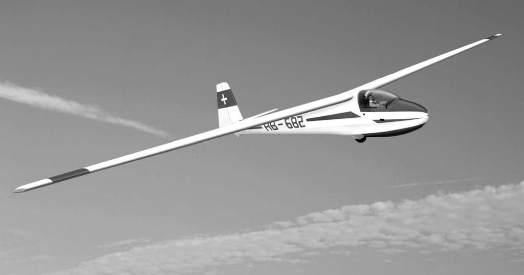


1 SPECIFICATION - Wingspan: 3500mm (137.8 in) - Length: 1650mm (64.96 in) - Flying weight: gr - Wing area: 75 dm2 - Wing loading: 49g/dm2 - Wing type: HQ profile - Covering type: Genuine ORACOVER - Radio: 6 channel minimum (not included) - Servo: 4 standard servo: 2 aileron; 1 elevator; 1 rudder (not included) - Recommended receiver battery: 6.0V 1200mAh NiMH (not included) - Servo mount: 21mm x 42 mm - Flap: 2 electric flaps 440mm (not included) - Propeller: suit with your engine - Motor: brushless outrunner W, 800 KV (not included) - Gravity CG: 80 mm (3,9 in) Back from the leading edge of the wing, at the fuselage - Control throw Ailerons: Low: 10mm up/down, 10% expo; High: 15mm up/down, 10% expo - Control throw Elevators: Low: 8mm up/down, 12% expo; High: 12mm up/down, 12% expo - Control throw Rudder: Low: 30mm right/left, 15% expo; High: 45mm right/left, 15% expo - Experience level: Intermediate - Plane type: Scale Sailplane
2
3 TOOLS AND SUPPLIES NEEDED. PREPARATIONS Medium C/A glue. 30 minute epoxy. 6 minute epoxy. Hand or electric drill. Assorted drill bits. Modeling knife. Straight edge ruler. 2 bender plier. Wire cutters. Masking tape. Thread lock. Paper towels. Rubbing alcohol Remove the tape and separate the ailerons from the wing and the elevators from the stab. Use a covering iron with a covering sock on high heat to tighten the covering if necessary. Apply pressure over sheeted areas to thoroughly bond the covering to the wood. SUGGESTION To avoid scratching your new airplane, do not unwrap the pieces until they are needed for assembly. Cover your workbench with an old towel or brown paper, both to protect the aircraft and to protect the table. Keep a couple of jars or bowls handy to hold the small parts after you open the bag. 1 INSTALLING THE AILERONS 3. Test fit the ailerons to the wing with the hinges. If the hinges don t remain centered, stick a pin through the middle of the hinge to hold it in position. NOTE: Please trial fit all the parts. Make sure you have the correct parts and that they fit and are aligned properly before gluing! This will assure proper assembly. The ELECTRIC 3500 ARF 1/4 ¼ SCALE is hand made from natural materials, every plane is unique and minor adjustments may have to be made. However, you should find the fit superior and assembly simple. TEMPORARY PIN TO KEEP HINGE CENTERED The painted and plastic parts used in this kit are fuel proof. However, they are not tolerant of many harsh chemicals including the following: paint thinner, C/A glue accelerator, C/A glue debonder and acetone. Do not let these chemicals come in contact with the colors on the covering and the plastic parts. 5. Apply six drops of thin CA to the top and bottom of each hinge. Do not use CA accelerator. After the CA has fully hardened, test the hinges by pulling on the aileron. SAFETY PRECAUTION: This is not a toy Be sure that no other flyers are using your radio frequency. Do not smoke near fuel Store fuel in a cool, dry place, away from children and pets. Wear safety glasses. The glow plug clip must be securely attached to the glow plug. Do not flip the propeller with your fingers. Keep loose clothing and wires away from the propeller. Do not start the engine if people are near. Do not stand in line with the side of the propeller. Make engine adjustments from behind the propeller only. Do not reach around the spinning propeller. CA glue 2 1
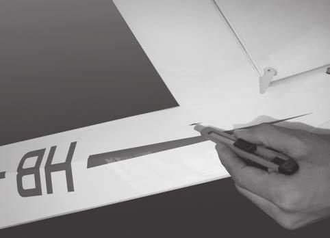
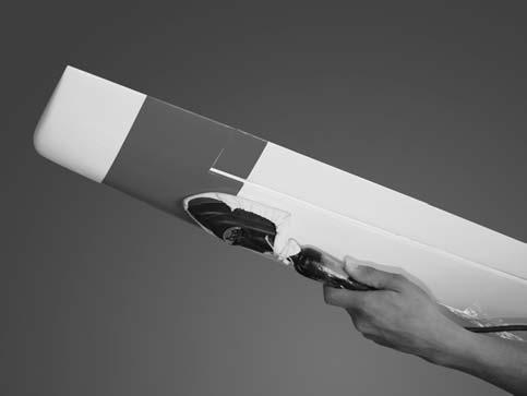
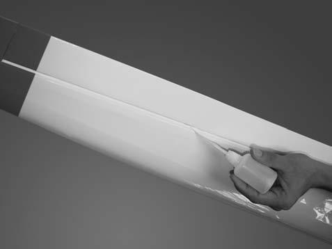
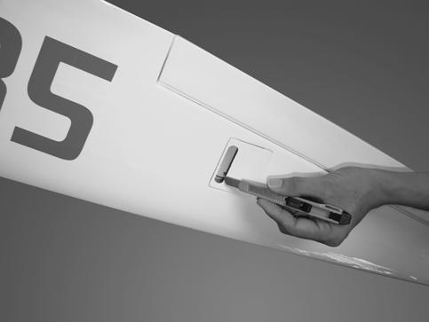
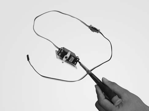
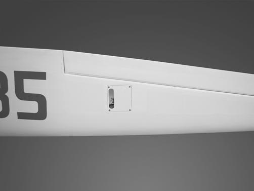
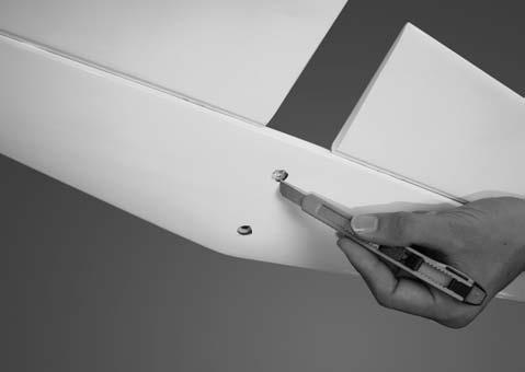
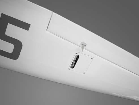
4 INSTALLING THE AILERON SERVOS 5. Place the aileron servo tray / hatch into the servo box on the bottom of the wing and drill 1,6mm pilot holes through the tray and the servo box for each of the four mounting screws. Secure the servo tray in place using the mounting screws provided ( 2mm x 12mm ). 1. Install the rubber grommets and brass eyelets onto the aileron servo. 2. Using a modeling knife, remove the covering from over the pre-cut servo arm exit hole on the aileron servo tray / hatch. This hole will allow the servo arm to pass through when installing the aileron pushrods. Remove the covering To the cowl 6 6. Repeat step # 2 - # 5 to install the second aileron servo in the opposite wing half Place the servo into the servo tray. Center the servo within the tray and drill 1,6mm pilot holes through the block of wood for each of the four mounting screws provided with the servo. To the cowl 7 7. Using masking tape, tape the servo leads on to the top of the wing. 4 INSTALLING THE CONTROL HORNS 4. Using the thread as a guide and using masking tape, tape the servo lead to the end of the thread: carefully pull the thread out. When you have pulled the servo lead out, remove the masking tape and the servo lead from the thread. 1. One aileron control horn in positioned on each aileron. Using a ruler and a pen, locate and mark the location of the control horn. It should be mounted on the bottom side of the aileron at the leading edge, in line with the aileron pushrod. 2. Drill 3mm holes through the aileron using the control horn as a guide and screw the control horn in place. Servo lead 5 2
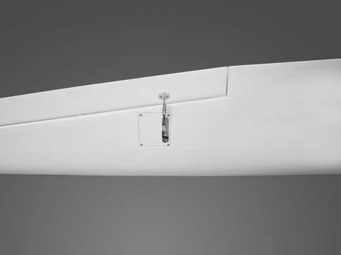
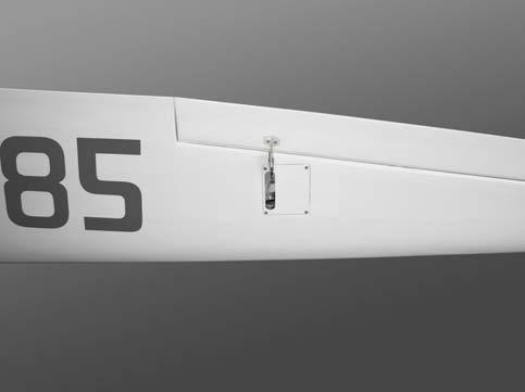
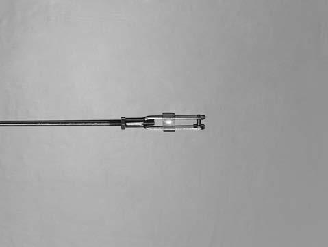
5 6. With the aileron and aileron servo centered, carefully place a mark on the aileron pushrod wire where it crosses the hole in the servo arm. 7. Using pliers, carefully make a 90 degree bend down at the mark made. Cut off the excess wire, leaving about 4mm beyond the bend. 8. Insert the 90 degree bend down through the hole in the servo arm. Install one nylon snap keeper over the wire to secure it to the arm. Install the servo arm retaining screw and remove the masking tape from the aileron. 8 To the cowl Silicone Tube RIGHT WRONG 3. Repeat step # 1 - # 2 to install the control horn on the opposite aileron. 10 INSTALLING THE AILERON LINKAGES 9. Repeat step # 4 - # 8 to install the second aileron linkage. After both linkages are completed, connect both of the aileron servo leads using a Y-harness you have purchased separately. 1. Working with the aileron linkage for now, thread one nylon clevis at least 14 turns onto one of the 2mm x 180mm threaded wires. To the cowl Attach the clevis to the outer hole in the control horn. Install a silicone tube on the clevis. INSTALLING THE HORIZONTAL STABILIZER 3. Locate one nylon servo arm, and using wire cutters, remove all but one of the arms. Using a 2mm drill bit, enlarge the third hole out from the center of the arm to accommodate the aileron pushrod wire. 1. Remove the covering. 4. Plug the aileron servo into the receiver and center the servo. Install the servo arm onto the servo. The servo arm should be perpendicular to the servo and point toward the middle of the wing. Remove the covering 5. Center the aileron and hold it in place using a couple of pieces of masking tape. 12 3
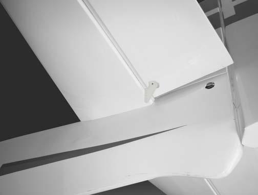
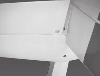
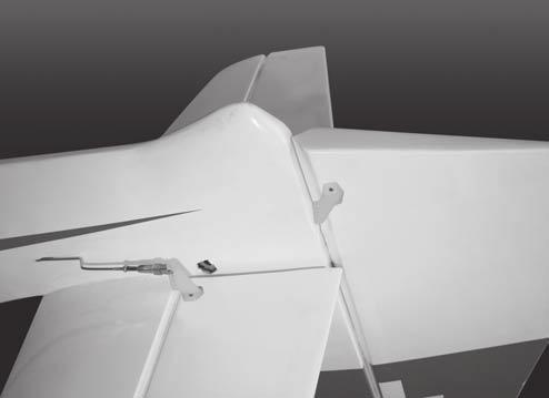
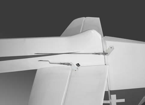
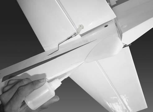
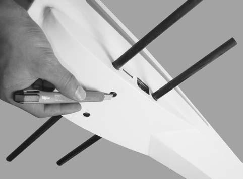
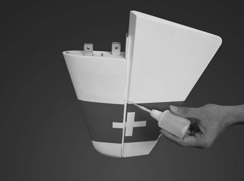
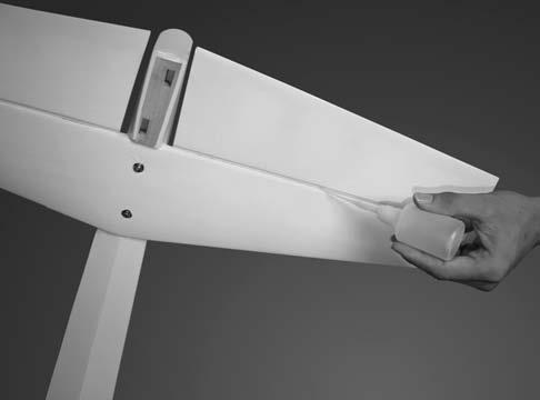
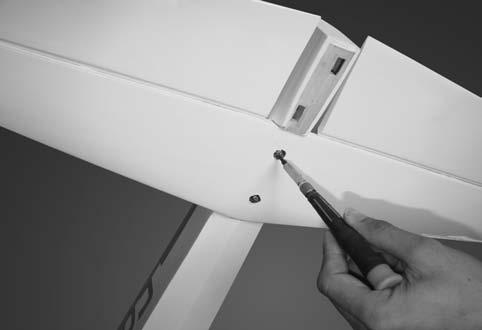
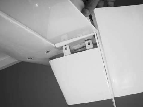
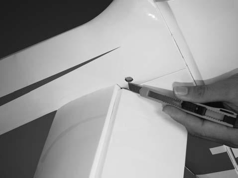
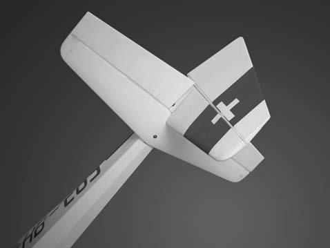
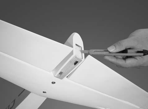
6 13 4. Secure the horizontal onto the fuselage. 2. Attach the wing to the fuselage as picture. Remove the covering Screw INSTALLING THE elevator - Repeat step #1 - #5 from installing the aileron to install the elevator. Dihedral brace 15 C.A glue 18 Screw INSTALLING THE RUDDER 1. Repeat step #1 - #5 from installing the aileron to install the rudder Test the position of the elevator and adjust it as shown. C.A glue 19 4
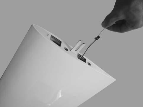
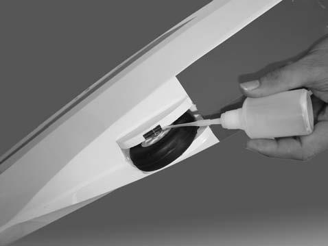
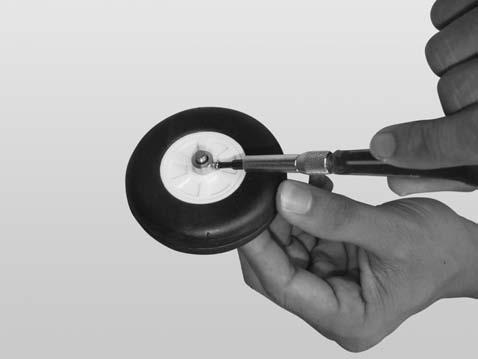
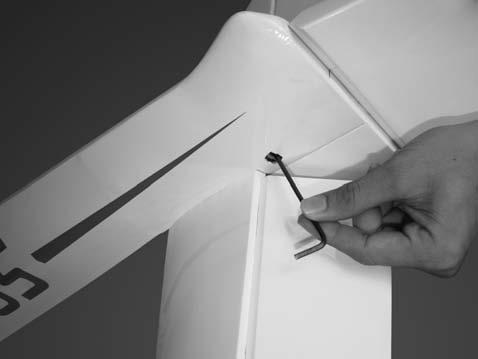
7 2. Remove the covering from the fuselage. Remove the covering INSTALLING THE main landing gear 3. Insert the vertical stabilizer into the fuselage. 1. The full set wheel Remove the covering from the fuselage. 2. Secure the collars. Remove the covering Glue the wooden plate to the fuselage. 5. Secure the vertical stabilizer into the fuselage. C.A glue Screw
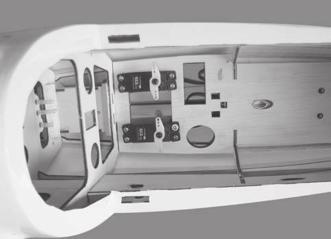
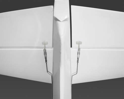
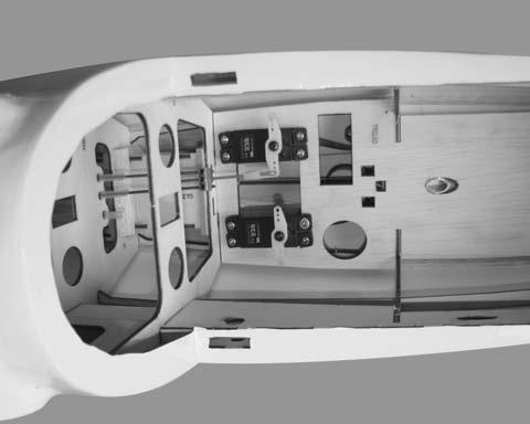
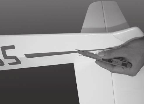
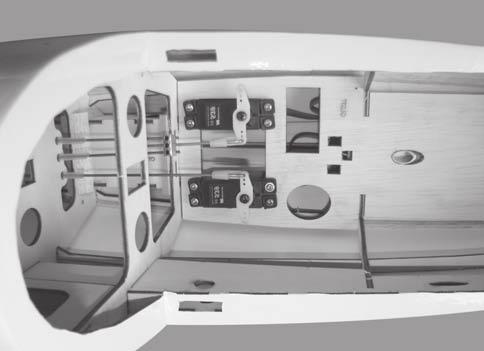
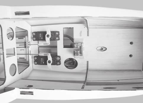
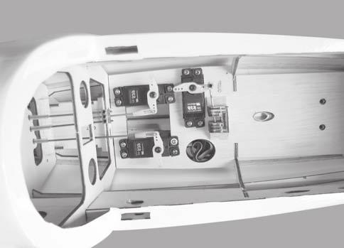
8 SERVO INSTALLATION INSTALLING THE FUSELAGE SERVOS 1. Install the rubber grommets and brass collets into the elevator, rudder and towing servos. Test fit the servos into the servo tray. Trim the tray if necessary to fit your servos 2. Mount the servos to the tray using the mounting screws provided with your radio system. Control horn elevator 30 Rudder servo Elevator servo Control horn 28 INSTALLING THE ELEVATOR PUSHROD Control horn Locate the pushrod exit slot on the right side and left side of the fuselage. It is located slightly ahead and below the horizontal stabilizer. 7. Attach clevis to the third hole in the control horn. Install a silicone tube on the clevis. 2. Carefully cut away the covering material from the slot. Silicone tube Silicone tube 32 Remove the covering 8. Locate one nylon servo arm, and using wire cutters, remove all but one of the arms. Using a 2mm drill bit, enlarge the third hole out from the center to accommodate the elevator pushrod wire Working from inside the fuselage, slide the threaded end of the pushrod until it reaches the exit slot. Carefully reach in with a small screw driver and guide the pushrod out of the exit slot. 9. Plug the elevator servo into the receiver and center the servo. Install the servo arm onto the servo. The servo arm should be perpendicular to the servo and point toward the middle of the fuselage. 4. Install the clevis on the elevator pushrod. Make sure 6mm of thread shows inside the clevis. 10. Be sure both elevator halves are flat. Center both elevator halves and hold them in place using a couple of pieces of masking tape. 5. The control horn should be mounted on the bottom, left side and right side of the elevator at the leading edge, in line with the elevator pushrod. 11. Connect two elevator purshord to the metal domino connector and secure it. Insert the wire pushrod into the metal domino connector and secure it. 6. Drill 1.6mm holes through the elevator using the control horn as a guide and screw the control horn in place. 6
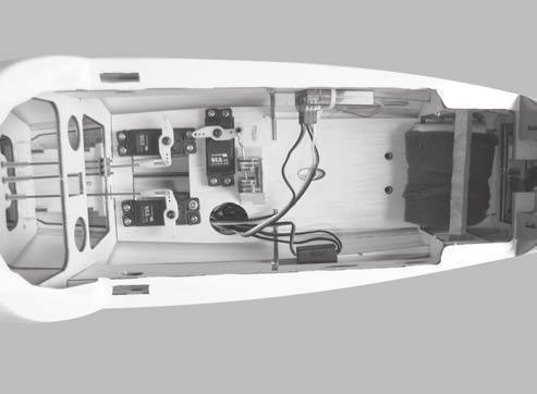
9 6. Drill 1.6mm holes through the rudder using the control horn as a guide and screw the control horn in place. 12. With the elevator halves and elevator servo centered, carefully place a mark on the elevator pushrod wire where it crosses the hole in the servo arm. 13. Using pliers, carefully make a 90 degree bend up at the mark made. Cut off the excess wire, leaving about 8mm beyond the bend. 14. Insert the 90 degree bend up through the hole in the servo arm, install one nylon snap keeper over the wire to secure it to the arm. Install the servo arm retaining screw and remove the masking tape the elevator halves. Control horn 15. Using thick CA glue, secure the pushrod sleeves to the pushrod sleeve guide Attach clevis to the third hole in the control horn. Install a silicone tube on the clevis. Metal Domino 33 Silicone tube INSTALLING THE RUDDER PUSHROD 1. Locate the pushrod exit slot on the left of the fuselage Carefully cut away the covering material from the slot. 8. Locate one nylon servo arm, and using wire cutters, remove all but one of the arms using a 2mm drill bit, enlarge the third hole out from the center to accommodate the rudder pushrod wire. 9. Plug the rudder servo into the receiver and center the servo. Install the servo arm onto the servo. 10. Center the rudder and hold it in place using a piece of masking tape. Remove the covering 11. With the rudder and rudder servo centered, carefully place a mark on the rudder pushrod wire where it crosses the hole in the servo arm Working from inside the fuselage, slide the threaded end of the remaining pushrod down the inside of the fuselage until the pushrod reaches the exit slot. Carefully reach in with a small screw driver and guide the pushrod out of the exit slot. 12. Using a pliers, carefully make a 90 degree bend up at the mark made. Cut off excess wire, leaving about 8mm beyond the bend. 13. Insert the 90 degree bend up through the hole in the servo arm. Install one nylon snap keeper over the wire to secure it to the arm. Install the servo arm retaining screw and remove the masking tape from the rudder. 4. Install the clevis on the rudder pushrod. Make sure 6mm of thread shows inside the clevis. 5. The control horn should be mounted on the left side of the rudder at the leading edge, in line with the rudder pushrod. 14.Using thick CA glue, secure the pushrod sleeves to the pushrod sleeve guide. 7
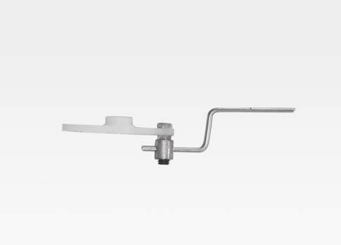
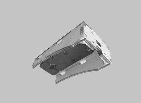
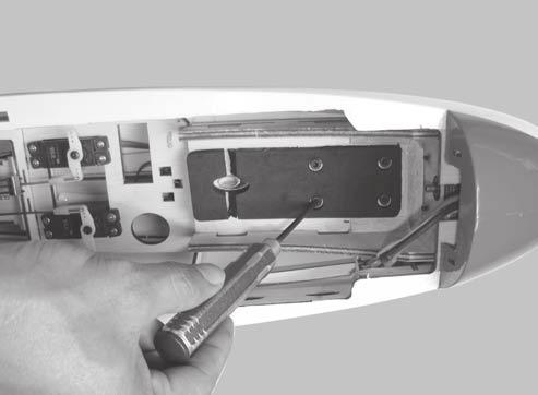
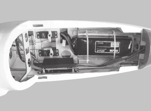
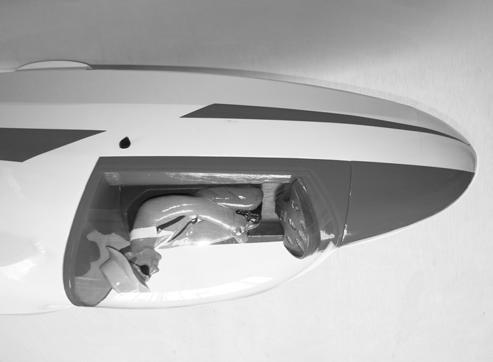
10 40 37 INSTALLING THE towing servo INSTALLING THE RECEIVER AND BATTERY 1. Install the metal connector to the servo arm. 1. Plug the servo leads and the switch lead into the receiver. You may want to plug an aileron extension into the receiver to make plugging in the aileron servo lead easier when you are installing the wing. Plug the battery pack lead into the switch. 2. Wrap the receiver and battery pack in the protective foam to protect them from vibration. Use a rubber band or masking tape to hold the foam in place Position the battery pack and receiver behind the fuel tank. Use the two light plywood pieces, placed over the battery and receiver and glue to the fuselage sides to hold the battery and receiver securely in place. Use 15mm triangle pieces glued between the fuselage sides and the plywood pieces to reinforce the joints. Bend L the metal rod as the picture below.! Do not permanently secure the receiver and battery until after balancing the model. 4. Using a 2mm drill bit, drill a hole through the side of the fuselage, near the receiver, for the antenna to exit. INSTALLING THE SWITCH The switch should be mounted on the fuselage side, opposite the muffler, close enough to the receiver so the lead will reach. Use the face plate of the switch cut out and locate the mounting holes. Place the servo arm to the servo and secure it. 2. Cut out the switch hole using a modeling knife. Use a 2mm drill bit and drill out the two mounting holes through the fuselage side. 3. Secure the switch in place using the two machine screws provided with the radio system. 39 8
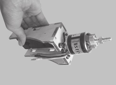
11 Switch Battery Screw Receiver INSTALLING THE MOTOR ESC Battery 47 Screw 43 ELECTRIC SETUP - Motor brushless rimfire Esc 60A. - Battery: 4 cells mah. - Propeller: 14 x 7 Remove the covering 44 9
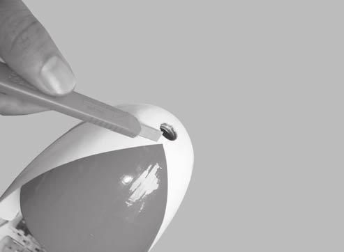
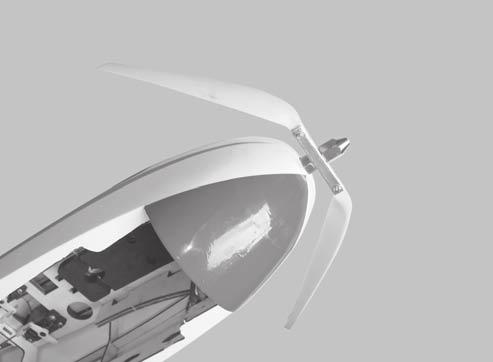
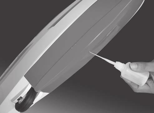
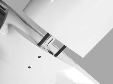
12 Open and close the canopy 2. Mount the wing to the fuselage. Using a couple of pieces of masking tape, place them on the top side of the wing 80mm back from the leading edge, at the fuselage sides. 3. Turn the airplane upside down. Place your fingers on the masking tape and carefully lift the plane. 4. If the nose of the plane falls, the plane is nose heavy. To correct this first move the battery pack further back in the fuselage. If this is not possible or does not correct it, stick small amounts of lead weight on the fuselage under the horizontal stabilizer. If the tail of the plane falls, the plane is tail heavy. To correct this, move the battery and receiver forward or if this is not possible, stick weight into the firewall. When balanced correctly, the airplane should sit level or slightly nose down when you lift it up with your fingers. Screw 48 - Glue the plastic cover to the fuselage. 80mm C.A glue 49 - Glue the plastic cover to the fuselage. LATERAL BALANCE! C.A glue After you have balanced a plane on the C.G. You should laterally balance it. Doing this will help the airplane track straighter. 5. Turn the airplane upside down. Attach one loop of heavy string to the engine crankshaft and one to the tail wheel wire. With the wings level, carefully lift the airplane by the string. This may require two people to make it easier. 6. If one side of the wing fall, that side is heavier than the opposite. Add small amounts of lead weight to the bottom side of the lighter wing half's wing tip. Follow this procedure until the wing stays level when you lift the airplane. 50 BALANCING 1. It is critical that your airplane be balanced correctly. Improper balance will cause your plane to lose control and crash. CONTROL THROWS 1. We highly recommend setting up a plane using the control throws listed. THE CENTER OF GRAVITY IS LOCATED 80mm BACK FROM THE LEADING EDGE OF THE WING, AT THE FUSELAGE. This location is recommended for initial test flying and trimming. BALANCE A PLANE UPSIDE DOWN WITH THE FUEL TANK EMPTY. 2. The control throws should be measured at the widest point of each control surface. 3. Check to be sure the control surfaces move in the correct directions. 10
13 Aileron : 10mm up Elevator : 8mm up Rudder : 30mm right 10mm down 8mm down 30 mm left 10mm 10mm Aileron Control 8mm 8mm Elevator Control FLIGHT PREPARATION 30mm 30mm PRE FLIGHT CHECK 1. Completely charge your transmitter and receiver batteries before your first day of flying. 2. Check every bolt and every glue joint in your plane to ensure that everything is tight and well bonded. 3. Double check the balance of the airplane. 4. Check the control surface. 5. Check the receiver antenna. It should be fully extended and not coiled up inside the fuselage. 6. Properly balance the propeller. Rudder Control 11
14 I/C FLIGHT WARNINGS Always operate in open areas, away from factories, hospitals, schools, buildings and houses etc. NEVER fly your aircraft close to people or built up areas. THE PROPELLER IS DANGEROUS Keep fingers, clothing (ties, shirt sleeves, scarves) or any other loose objects that could be caught or drawn in, away from the propeller. Take care at ALL times. Keep all onlookers (especially small children and animals) well back from the area of operation. This is a flying aircraft, which will cause serious injury in case of impact with a person or animal. NEVER fly near power lines, aerials or other dangerous areas including airports, motorways etc. NEVER use damaged or deformed propellers or spinners. NEVER fly in wet conditions or on windy or stormy days. ALWAYS adjust the engine from behind the propeller, and do not allow any part of your body to be in line with the propeller. DO NOT dispose of empty fuel containers on a fire, this can lead to an explosion.
15 I/C FLIGHT GUIDELINES When ready to fly, first extend the transmitter aerial. Switch on the transmitter. Operate the control sticks on the transmitter and check that the control surfaces move freely and in the CORRECT directions. ALWAYS land the model INTO the wind, this ensures that the model lands at the slowest possible speed. Check that the transmitter batteries have adequate power. Switch off the receiver. Switch on the receiver. Check that the wings are correctly fitted to the fuselage. ALWAYS take off into the wind. Switch off the transmitter. If the model does not respond correctly to the controls, land it as soon as possible and correct the fault. Empty the fuel tank after flying, fuel left in the tank can cause corrosion and lead to engine problems. Made in Vietnam
16
I n s t r u c t i o n M a n u a l. Instruction Manual SPECIFICATION
 I n s t r u c t i o n M a n u a l Instruction Manual SPECIFICATION - Wingspan: 3200mm (125,9 in) - Length: 1650mm (64,9 in) - Flying weight: 3000gr 3200gr - Wing area: 64.5 dm2 - Wing loading: 46g/dm2
RECOMMENDED MOTOR AND BATTERY SET UP
 SPECIFICATION - Wingspan: 6000mm (236.2 in) - Length: 2873mm (113.1 in) - Flying weight: 14-18 kg - Wing area: 219.4 dm2 - Wing loading: 64g/dm2 - Wing type: HQ airfoils - Covering type: Genuine ORACOVER
the leading edge of the wing, at the fuselage - Length: 1540mm (60.6 in) 10% expo; High: 15mm up/down, 10% expo - Wing area: 40dm2
 10% expo; High: 15mm up/down, 10% expo - Wing area: 40dm2") SPECIFICATION - Gravity CG: 165-170 mm (6.5-6.7 in) Back from - Wingspan: 1400mm (55.1 in) the leading edge of the wing, at the fuselage - Length: 1540mm (60.6 in) - Control throw Ailerons: Low: 12mm up/down,
SPECIFICATION - Gravity CG: 165-170 mm (6.5-6.7 in) Back from - Wingspan: 1400mm (55.1 in) the leading edge of the wing, at the fuselage - Length: 1540mm (60.6 in) - Control throw Ailerons: Low: 12mm up/down,
RECOMMENDED EDF AND BATTERY SET UP
 SPECIFICATION - Wingspan: 1150mm (45.3 in) - Length: 1587mm (62.5 in) - Flying weight: 5.0-5.3 kg - Wing area: 40dm2 - Wing loading: 125g/dm2 - Wing type: Naca airfoils - Covering type: Genuine ORACOVER
Instruction Manual. Wingspan : 2270mm (89.37 inches) : 1870mm (73.62 inches) : 7400gr gr. : 4 channel - 6 standard servo.
 : 1870mm (73.62 inches) : 7400gr gr. : 4 channel - 6 standard servo.") Wingspan : 2270mm (89.37 inches) g Length : 1870mm (73.62 inches) Weight : 7400gr - 7600gr Radio : 4 channel - 6 standard servo Engine : 25cc-35cc KIT CONTENTS: We have organized the parts as they come
Wingspan : 2270mm (89.37 inches) g Length : 1870mm (73.62 inches) Weight : 7400gr - 7600gr Radio : 4 channel - 6 standard servo Engine : 25cc-35cc KIT CONTENTS: We have organized the parts as they come
: 6 channel - 9 servo
 g Wingspan : 2005mm (78.94 inches) Length : 1640mm (64.57 inches) Weight : 6400g - 6600g Engine : 25cc - 35cc Radio : 6 channel - 9 servo KIT CONTENTS: We have organized the parts as they come out of
Instruction Manual. Specification:
 Instruction Manual L O W Specification: Wingspan: 133 cm (52.3 inches) Length : 104 cm (40.9 inches) Weight : 1790gr Engine : 25-32 two stroke Radio : 4 channel - 4 servo W I N G KIT CONTENTS: We have
RECOMMENDED MOTOR AND BATTERY SET UP
 SPECIFICATION - Wingspan: 2567mm (101in) - Length: 2190mm (86.2 in) - Flying weight: 11-13 kg - Wing area: 101 dm2 - Wing loading: 99g/dm2 - Wing type: Naca airfoils - Covering type: Genuine ORACOVER -
RECOMMENDED MOTOR AND BATTERY SET UP
 SPECIFICATION - Wingspan: 1420mm (55.91 in) - Length: 1370mm (53.94 in) - Flying weight: 2600-2800 gr - Wing area: 41.6 dm2 - Wing loading: 65g/dm2 - Wing type: Naca airfoils - Covering type: Genuine ORACOVER
RECOMMENDED MOTOR AND BATTERY SET UP
 SPECIFICATION - Wingspan: 1404mm (55.3in) - Length: 1134mm (44. 6 in) - Flying weight: 3.2-3.4 kg - Covering type: Genuine ORACOVER - Spinner size: scale type (not included) - Radio: 4 channel minimum
SIZE.120 OR 30CC SCALE 1:5 ARF
 PC21 PILATUS MK2 SIZE.120 OR 30CC SCALE 1:5 ARF SPECIFICATION - Wingspan: 1772mm (69.72in) - Length: 2019mm (79.5 in) - Flying weight: 6.4-7.2 kg - Wing area: 57.6 dm2 - Wing loading: 113g/dm2 - Wing type:
: 7 channel - 9 servo, Hi-Torque ( Minimum 6 kg ).
.") g Wingspan : 1820mm (71.65 inches) Length : 1625mm (63.98 inches) Weight : 6900gr Engine : 25cc - 35cc Radio : 7 channel - 9 servo, Hi-Torque ( Minimum 6 kg ). KIT CONTENTS: We have organized the parts
g Wingspan : 1820mm (71.65 inches) Length : 1625mm (63.98 inches) Weight : 6900gr Engine : 25cc - 35cc Radio : 7 channel - 9 servo, Hi-Torque ( Minimum 6 kg ). KIT CONTENTS: We have organized the parts
RECOMMENDED MOTOR AND BATTERY SET UP
 SPECIFICATION - Wingspan: 2190mm (86.2 in) - Length: 1907mm (75 in) - Flying weight: 9000-12000 gr - Wing area: 92 dm2 - Wing loading: 98g/dm2 - Wing type: Naca airfoils - Retract gear type: Air-retract
RECOMMENDED MOTOR AND BATTERY SET UP
 SPECIFICATION - Wingspan: 1410mm (55.5 in) - Length: 1278mm (50.3 in) - Flying weight: 3.2-3.4 kg - Wing area: 41.3 dm2 - Wing loading: 75g/dm2 - Wing type: Naca airfoils - Covering type: Genuine ORACOVER
HERO 3D SCALE 1:6 ARF
 Instruction Manual SPECIFICATION - Wingspan: 1500mm(59 in) - Length: 1410mm (55.5 in) - Flying weight: 2100-2300 gr - Wing area: 58 dm2 - Wing loading: 39g/dm2 - Covering type: Genuine ORACOVER - Gear
Instruction Manual. Wingspan : 1884 mm (74.17 in) Length. Weight. Engine. : 4 channels / 5 servo standard. : 1450 mm (57.
 Length. Weight. Engine. : 4 channels / 5 servo standard. : 1450 mm (57.") Wingspan : 1884 mm (74.17 in) Length : 1450 mm (57.09 in) Weight : 4000 gr Engine : 60 two strokes Radio : 4 channels / 5 servo standard KIT CONTENTS: We have organized the parts as they come out of the
Wingspan : 1884 mm (74.17 in) Length : 1450 mm (57.09 in) Weight : 4000 gr Engine : 60 two strokes Radio : 4 channels / 5 servo standard KIT CONTENTS: We have organized the parts as they come out of the
Instruction Manual. Wingspan : 1694mm (66.69 in) : 1470mm (57.87 in) : 3200gr gr. : 61 two stroke/ 71 four stroke. : 6 channel / 7 servo
 : 1470mm (57.87 in) : 3200gr gr. : 61 two stroke/ 71 four stroke. : 6 channel / 7 servo") Wingspan : 1694mm (66.69 in) g Length : 1470mm (57.87 in) Weight : 3200gr - 3800gr Engine : 61 two stroke/ 71 four stroke Radio : 6 channel / 7 servo KIT CONTENTS: We have organized the parts as they
Wingspan : 1694mm (66.69 in) g Length : 1470mm (57.87 in) Weight : 3200gr - 3800gr Engine : 61 two stroke/ 71 four stroke Radio : 6 channel / 7 servo KIT CONTENTS: We have organized the parts as they
RECOMMENDED MOTOR AND BATTERY SET UP
 SPECIFICATION - Wingspan: 1600mm (63 in) - Length: 1285mm (50.5 in) - Flying weight: 2800-3200 gr - Wing area: 40.1 dm2 - Wing loading: 78g/dm2 - Wing type: Naca airfoils - Covering type: Genuine ORACOVER
RECOMMENDED MOTOR AND BATTERY SET UP
 SPECIFICATION - Wingspan: 1800mm (70.8 in) - Length: 1355mm (53.3 in) - Flying weight: 4100-4300 g - Wing area: 51 dm2 - Wing loading: 80g/dm2 - Wing type: Naca airfoils - Covering type: Genuine ORACOVER
RECOMMENDED MOTOR AND BATTERY SET UP
 SPECIFICATION - Wingspan: 1669mm (65.7in) - Length: 1229mm (48.43 in) - Flying weight: 3300-3400 gr - Wing area: 44.2 dm2 - Wing loading: 67g/dm2 - Wing type: Naca airfoils - Covering type: Genuine ORACOVER
Instruction Manual. Wingspan : 1400 mm (55.12 inch) : 1480 mm (58.27 inch) : 5500gr gr. : 6-9 channel/ 8 servo high torque,1 standard
 : 1480 mm (58.27 inch) : 5500gr gr. : 6-9 channel/ 8 servo high torque,1 standard") Wingspan : 1400 mm (55.12 inch) g Length : 1480 mm (58.27 inch) Weight : 5500gr - 6000gr Radio : 6-9 channel/ 8 servo high torque,1 standard Engine : GT 22 OS KIT CONTENTS: We have organized the parts
Wingspan : 1400 mm (55.12 inch) g Length : 1480 mm (58.27 inch) Weight : 5500gr - 6000gr Radio : 6-9 channel/ 8 servo high torque,1 standard Engine : GT 22 OS KIT CONTENTS: We have organized the parts
Instruction Manual. Wingspan : 1400mm (55.12 in) : 1370mm (53.94 in) : 2600gr gr. : 4 channel / 5 servo. : / 2 stroke_52-71 / 4 stroke
 : 1370mm (53.94 in) : 2600gr gr. : 4 channel / 5 servo. : / 2 stroke_52-71 / 4 stroke") Instruction Manual 540 Wingspan : 1400mm (55.12 in) g Length : 1370mm (53.94 in) Weight : 2600gr - 2800gr Radio : 4 channel / 5 servo Engine : 46-52 / 2 stroke_52-71 / 4 stroke KIT CONTENTS: We have organized
Instruction Manual 540 Wingspan : 1400mm (55.12 in) g Length : 1370mm (53.94 in) Weight : 2600gr - 2800gr Radio : 4 channel / 5 servo Engine : 46-52 / 2 stroke_52-71 / 4 stroke KIT CONTENTS: We have organized
RECOMMENDED MOTOR AND BATTERY SET UP
 SPECIFICATION - Wingspan: 2000mm (78.7in) - Length: 1544mm (60.7 in) - Flying weight: 3600-3800 gr - Wing area: 66 dm2 - Wing loading: 55g/dm2 - Wing type: Naca airfoils - Covering type: Genuine ORACOVER
RECOMMENDED MOTOR AND BATTERY SET UP
 Instruction Manual SPECIFICATION - Wingspan: 1418mm (55.8 in) - Length: 1314mm (51.7 in) - Flying weight: 2700-3200 gr - Wing area: 36.8 dm2 - Wing loading: 76g/dm2 - Wing type: Naca airfoils - Covering
to fly. Most hardware included and all replacement parts are available.
 Instruction Manual The Thunderbolt P47 was perhaps the greatest of world war II in terms of all round performance and capability Phoenix Model has recreated a 2C - 60 class engine (or 4c 91 class) It was
SBD DAUNTLESS GP/EP SIZE ARF SCALE 1:8. Instruction Manual
 GP/EP SIZE.46-.55 ARF SCALE 1:8 SPECIFICATION - Wingspan: 1440mm (56.7in) - Length: 1140mm (44.9 in) - Flying weight: 3000-3300 g - Wing area: 42 dm2 - Wing loading: 78g/dm2 - Wing type: Naca airfoils
SBACH SCALE 1:4 ½ ARF
 SPECIFICATION - Wingspan: 1663mm (65.5 in) - Length: 1638mm (64.5 in) - Flying weight: 4700-5200 gr - Wing area: 56 dm2 - Wing loading: 85g/dm2 - Wing type: Naca airfoils - Covering type: Genuine ORACOVER
HIGH WING MK2 GP/EP ARF SCALE
 SONIC HIGH WING MK2 GP/EP.25-.32 ARF SCALE 1:10 SPECIFICATION - Wingspan: 1340mm (52.7in) - Length: 1040mm (40.9 in) - Flying weight: 1800-2000 gr - Wing area: 27 dm2 - Wing loading: 79g/dm2 - Wing type:
1660mm (65.4 in) 1200mm (47.2 in) 2700gr gr 6 channel - 7 servo standard 46/ 2 stroke or 52/ 4 stroke
 1200mm (47.2 in) 2700gr gr 6 channel - 7 servo standard 46/ 2 stroke or 52/ 4 stroke") Instruction Manual CESSNA-46 1660mm (65.4 in) 1200mm (47.2 in) 2700gr - 3000gr 6 channel - 7 servo standard 46/ 2 stroke or 52/ 4 stroke KIT CONTENTS: We have organized the parts as they come out of the
Instruction Manual CESSNA-46 1660mm (65.4 in) 1200mm (47.2 in) 2700gr - 3000gr 6 channel - 7 servo standard 46/ 2 stroke or 52/ 4 stroke KIT CONTENTS: We have organized the parts as they come out of the
Instruction Manual MUSTANG P51 - EP. Wingspan : 1377mm (54.21in) : 1180mm (46.46 in) : 2200gr gr. : AXI motor 2826 or 4120
 : 1180mm (46.46 in) : 2200gr gr. : AXI motor 2826 or 4120") Instruction Manual MUSTANG P51 - EP Wingspan : 1377mm (54.21in) g Length : 1180mm (46.46 in) Weight : 2200gr - 2600gr Engine : AXI motor 2826 or 4120 Radio : 4 channel / 4 servos standard KIT CONTENTS:
Instruction Manual MUSTANG P51 - EP Wingspan : 1377mm (54.21in) g Length : 1180mm (46.46 in) Weight : 2200gr - 2600gr Engine : AXI motor 2826 or 4120 Radio : 4 channel / 4 servos standard KIT CONTENTS:
Instruction Manual. Wingspan : 1670mm. : 3400gr gr. : 61/75 two stroke. : 5 servo + 1 servo retract / 6 channel
 Wingspan : 1670mm g Length Weight Engine Radio : 1350mm : 3400gr - 4000gr : 61/75 two stroke : 5 servo + 1 servo retract / 6 channel KIT CONTENTS: We have organized the parts as they come out of the box
TUCANO 60CC SCALE 1:4 ¼ ARF. Instruction Manual. version. version
 Instruction Manual GP EP version version SCALE 1: ¼ ARF SPECIFICATION - Wingspan: 567mm (101in) - Length: 190mm (86. in) - Flying weight: 11-13 kg - Wing area: 101 dm - Wing loading: 99g/dm - Wing type:
YAK54 MK2. GP/EP size.120/20cc SCALE 1:4 ¾ ARF. Instruction Manual. version. version
 Instruction Manual GP EP version version GP/EP size.10/0cc SCALE 1:4 ¾ ARF SPECIFICATION - Wingspan: 168 (66.3 in) - Length: 1605mm (63.1 in) - Flying weight: 4700-500 gr - Wing area: 54.7 dm - Wing loading:
Instruction Manual book
 book ITEM CODE:BH 115. SPECIFICATION Wingspan : 6,000 mm 236,22 in. Length : 2,740 mm 107,87 in. Weight : 17.5kg 38.5Lbs. Radio : 08 channels. Servo : 07-08 HS-5685MH(HITEC) Battery : 2 Cells-Li-Po 7.4V
Instruction Manual EXTRA 260-EP. 1075mm (42.32 in) 1000mm (39.37 in) 1100gr gr. 4 channel - 4 mini servo. Axi motor 2820
 1000mm (39.37 in) 1100gr gr. 4 channel - 4 mini servo. Axi motor 2820") 1075mm (42.32 in) 1000mm (39.37 in) 1100gr - 1400gr 4 channel - 4 mini servo Axi motor 2820 KIT CONTENTS: We have organized the parts as they come out of the box for better identification during assembly.
1075mm (42.32 in) 1000mm (39.37 in) 1100gr - 1400gr 4 channel - 4 mini servo Axi motor 2820 KIT CONTENTS: We have organized the parts as they come out of the box for better identification during assembly.
Instruction Manual book
 Instruction Manual book ITEM CODE:BH118. SPECIFICATION Wingspan : 1,050 mm 41.34 inches. Length : 950mm 37.4 inches. Weight : 1 kg 2.2 lbs. Radio : 04 channels. Servo : 4 mini servos. Motor : KMS 2814/05
Instruction Manual book
 book Item code:bh131 SPECIFICATION Wingspan : 3,000 mm 118.1 in. Length : 1,600 mm 62.99 in. Weight : 2.2 kg 4.84 Lbs. Radio : 05 channels. Servo : 06 mini servos. Electric Motor: BOOST 40 Battery : 3celIs
INSTRUCTION MANUAL BOOK
 INSTRUCTION MANUAL BOOK ITEM CODE BH57. SPECIFICATION Wingspan: 1,470 mm. 57.87 in. Length : 1,180 mm. 46.46 in. Weight : 2.7 Kg. 5.94 Lbs. Engine : 46 cu.in 2 stroke. 52 cu.in 4 stroke. Radio : 4 channels.
Instruction Manual book
 book SPECIFICATION Wingspan : 1,450 mm 57.09 in. Length : 1,200mm 47.24in. Weight : 3.1 kg 6.82 Lbs. Radio : 05 channels. Servo : 07 servos. Engine : 61-75 2 stroke. 91 4 stroke. Made in Vietnam. This
Instruction Manual book
 Instruction Manual book SPECIFICATION Wingspan : 1,800mm. 70.87 in. Length : 1,350 mm. 53.15in. Weight : 3.6kg. 7.92lbs. Parts Listing required (not included). Glow Engine : 55-61 2 stroke. 91 4 stroke.
Instruction Manual. We wish you many enjoyable flights with your plane and once again thank you for your choosing a Phoenix Model product
 Instruction Manual Wing span: 1590mm (626 in) Length: 1100mm (433 in) Weight: 1500gr - 1700gr Motor: AXI 2814/10 or Motor: 500-600 w/ gear box Radio: 4 Channel / 4 servos standar Propeller: 12 x 47 We
Instruction Manual book
 Instruction Manual book Item code:bh133 SPECIFICATION Wingspan : 1,400 mm 55.12 in. Length : 1,350 mm 53.15 in. Weight : 3.7 kg 8.14 Lbs. Radio : 08-09 channels. Servo : 08-09 servos. EDF : Turingy SK3
Instruction Manual book
 Instruction Manual book ITEM CODE:BH118. SPECIFICATION Wingspan : 1,050 mm 41.34 inches. Length : 950mm 37.4 inches. Weight : 1 kg 2.2 lbs. Radio : 04 channels. Servo : 4 mini servos. Motor : BL2215/20
Instruction Manual book
 book ITEM CODE:BH 145 SPECIFICATION Wingspan: 6,000mm 236.22 in. Length : 2,800 mm 110.24 in. Weight : 18.5 kg 40.7 Lbs. Parts listing required (not included). Radio : 07-08 channels. Servo : 09-10 standard
Instruction Manual book
 book SPECIFICATION Wingspan : 1,920 mm 75.59 in. Length : 1,560 mm 61.42 in. Weight : 5 kg 11.00Lbs. Radio : 06 channels. Servo : 09 servos. Engine : 120 4 stroke. Made in Vietnam. This instruction manual
TURBO BEAVER. Instruction Manual Book. Item code: BH % ALMOST READY TO FLY ALL BALSA - PLY WOOD CONSTRUCTION. COVERED WITH ORACOVER
 Instruction Manual Book. TURBO BEAVER ALL BALSA - PLY WOOD CONSTRUCTION. COVERED WITH ORACOVER 95% ALMOST READY TO FLY SPECIFICATION: - Wingspan: 2,250 mm (88.58 in). Length: 1,675 mm ( 65.94 in). Weight:
Instruction Manual book
 book ITEM CODE:BH 139 SPECIFICATION Wingspan : 1,450mm 57.09 in. Length : 1,140 mm 44.88 in. Weight : 3.3kg 7.26 Lbs. Radio : 05 channels. Servo : 07 mini servos+ 3servos Retracts (FUTABA S3170G) EDF:
Instruction Manual book
 Instruction Manual book ITEM CODE:BH135 SPECIFICATION Wingspan : 4,200mm. 163.35 in. Length : 2,100 mm. 82.68 in. Weight : 7,6 kg. 16.72lbs Radio : 07 channels. Servo : 05 06 standard high torque servos,
Instruction Manual BULLDOG. Wingspan : 1410 mm (55.5in) : 1450 mm (57.1in) : 4900gr gr. Weight. : 6-9 Channel/ 7 servo high torque, 1standard
 : 1450 mm (57.1in) : 4900gr gr. Weight. : 6-9 Channel/ 7 servo high torque, 1standard") Wingspan : 1410 mm (55.5in) Length Weight Radio Engine : 1450 mm (57.1in) : 4900gr - 5600gr : 6-9 Channel/ 7 servo high torque, 1standard : 1.20/ 2 stroke 1.80/ 4 stroke KIT CONTENTS: We have organized
Wingspan : 1410 mm (55.5in) Length Weight Radio Engine : 1450 mm (57.1in) : 4900gr - 5600gr : 6-9 Channel/ 7 servo high torque, 1standard : 1.20/ 2 stroke 1.80/ 4 stroke KIT CONTENTS: We have organized
Instruction Manual book
 Instruction Manual book SPECIFICATION Wingspan : 1,920 mm 75.59 in. Length : 1,560 mm 61.42 in. Weight : 5 kg 11.00Lbs. Radio : 06 channels. Servo : 09 servos. Engine : 120 4 stroke. Made in Vietnam. JU87-STUKA
Instruction Manual book
 Instruction Manual book SPECIFICATION Wingspan : 1,920 mm 75.59 in. Length : 1,560 mm 61.42 in. Weight : 5 kg 11.00Lbs. Radio : 06 channels. Servo : 09 servos. Engine : 120 4 stroke. Made in Vietnam. JU87-STUKA
Instruction Manual book
 book SPECIFICATION Wingspan : 2,080 mm 81.89 in. Length : 1,680 mm 66.14 in. Weight : 6.2 kg 13.64 Lbs. Radio : 06 channels. Servo : 06 servos. Engine : 30-35 CC Gas(FUJI IMVAC). Made in Vietnam. This
Instruction Manual book
 book SPECIFICATION Wingspan : 2,310 mm 90.94 in. Length : 1,750 mm 68.90 in. Weight : 8.4 kg 18.48 Lbs. Radio : 06 channels. Servo : 09 servos + 2 mini servos (elevator). Engine : 45-55CC gas. Made in
Instruction Manual book
 book (pusher propeller) ITEM CODE:BH 142 SPECIFICATION Wingspan : 1,450mm 57.09 in. Length : 1,165 mm 45.87 in. Weight : 3.3kg 7.26 Lbs. Radio : 05 channels. Servo : 07 size (29 x 13 x 30) mm. Electric
Instruction Manual book
 Instruction Manual book Item code:bh144 SPECIFICATION Wingspan : 1,400 mm 55.12 in. Length : 1,350 mm 53.15 in. Weight : 4 kg 8.8 Lbs. Empty Weight: 1.9 kg 4.18 lbs Radio : 08 channels. Servo : 08 size
Instruction Manual book
 book SPECIFICATION Wingspan : 1.750mm 68.90 in. Length : 1.280 mm 50.39 in. Weight : 3.2-3.5 kg 7.04-7.7 Lbs. Radio : 06 channels. Servo : 07-09 mini servos +3 servos retracts (FUTABA,S3170G) Parts listing
Instruction Manual book
 Instruction Manual book SPECIFICATION Wingspan : 2,170 mm 85.43 in. Length : 1,760 mm 69.29 in. Weight : 6.3 kg 13.86 Lbs. Radio : 06 channels. Servo : 08 servos. Engine : 45-50CC Gas. Made in Vietnam.
Instruction Manual book
 Instruction Manual book Item code:bh117 SPECIFICATION Wingspan : 2,100 mm 82.68 in. Length : 1,875 mm 73.82 in. Weight : 7.5 kg 16.5 Lbs. Parts listing required (not included) Radio : 08 channels. Servo
Instruction Manual book
 book ITEM CODE: BH99. SPECIFICATION Wingspan : 2,850 mm 112.20 in. Length : 1,910 mm 75.20 in. Weight : 8.1 kg 17.82 Lbs. Radio : 06 channels. Servo : 08 servos. Engine : 35 CC gas. Made in Vietnam. This
Instruction Manual book
 Instruction Manual book ITEM CODE: BH39. SPECIFICATION Wingspan : 181 cm 71.26 inches. Length : 155 cm 61.024 inches. Weight : 04 kg 8.8 lbs. Servo : 9 servos. Radio : 6 channels. Engine : 91 cu.in - 2
ALMOST READY TO FLY. Wing Span in cm. 2
 ASSEMBLY MANUAL ALMOST READY TO FLY MS:X9 Specifications Wing Span --------------------------61.4 in ---------------------------156cm. 2 Wing Area --------------------------606.1 sq.in ------------------
P-40C TOMAHAWK. Instruction Manual Book. Item code: BH % ALMOST READY TO FLY SPECIFICATION
 Instruction Manual Book. P-40C TOMAHAWK INCLUDING AIR RETRACT. AIR UP, AIR DOWN, TURN AND TWIST OLEO STRUTS LANDING GEAR. ALL BALSA - PLY WOOD CONSTRUCTION. COVERED IN A HEAT-SHRINK FILM WITH PRINTED.
Instruction Manual book
 book ITEM CODE:BH 124 SPECIFICATION Wingspan : 2,240 mm 88.19 in. Length : 1,625 mm 63.98 in. Weight : 6,4 kg 14.08Lbs. Radio : 08 channels. Servo : 09 servos. Engine : 26-35cc Gas. Made in Vietnam. This
SUPER DECATHLON. Instruction Manual Book 95% ALMOST READY TO FLY. Item code: BH150. SPECIFICATION
 Instruction Manual Book Item code: BH150. SUPER DECATHLON ALL BALSA - PLY WOOD CONSTRUCTION. COVERED WITH ORACOVER. 95% ALMOST READY TO FLY SPECIFICATION Wingspan: 2,450mm (96.46in). Length: 1,750mm (68.90in).
Instruction Manual book
 Instruction Manual book Item code:bh117 SPECIFICATION Wingspan : 2,100 mm 82.68 in. Length : 1,875 mm 73.82 in. Weight : 7.5 kg 16.5 Lbs. Radio : 08 channels. Servo : 09 servos. Engine : 33-45cc gas. Made
Instruction Manual book
 Instruction Manual book ITEM CODE:BH 140 SPECIFICATION Wingspan : 2,050mm 80.71 in. Length : 1,840 mm 72.41 in. Weight : 6.8kg 14.96 Lbs. Radio : 07 channels. Servo : 09 servos. Engine: O.S GT 33 CC gas.
Instruction Manual book
 Instruction Manual book ITEM CODE: BH122. SPECIFICATION Wingspan : 2,200 mm 86.61 in. Length : 1,640 mm 64.57 in. Weight : 6.5 kg 14.3Lbs. Parts listing required (not included). Radio : 8 channels. Servo
Instruction Manual book
 Instruction Manual book ITEM CODE: BH56. SPECIFICATION Wingspan : 1,660 mm 65.35 in. Length : 1,420 mm 55.91 in. Weight : 3.8 kg 8.36 Lbs. Radio : 06 channels. Servo : 08 servos. Engine : 75 Cu.in 2 Stroke.
Instruction Manual book
 book ITEM CODE:BH 72 SPECIFICATION Wingspan : 2,350 mm 92.52 in. Length : 1,730 mm 68.11 in. Weight : 6.4 kg 14.08 Lbs. Radio : 06 channels. Servo : 08 servos. Engine : OS. GT22-26cc gas. Made in Vietnam.
Instruction Manual book
 book Item code:bh77 SPECIFICATION Wingspan : 1,740 mm 68.50 in. Length : 1,440 mm 56.69 in. Weight : 4.4 kg 9.68 Lbs. Radio : 06 channels. Servo : 09 servos + 2 mini servos(wheel door). Engine : 120-4
MESSERSCHMITT BF-109E
 Instruction Manual Book Item code: BH146. MESSERSCHMITT BF-109E ALL BALSA - PLY WOOD CONSTRUCTION. COVERED IN A HEAT-SHRINK FILM WITH PRINTED. 95% ALMOST READY TO FLY SPECIFICATION Wingspan: 1,650 mm (64.96
INSTRUCTION MANUAL BOOK
 INSTRUCTION MANUAL BOOK ITEM CODE: BH 36. SPECIFICATION Wingspan : 1,620 mm 64 in. Length : 1,340 mm 53 in. Weight : 3.8 Kg 8.36 Lbs. Engine : 15 CC Gas Radio : 8 Channels Servo : 8Servos + 2 servos Retract
Instruction Manual book
 book ITEM CODE:BH 136 SPECIFICATION Wingspan : 2,000mm 78.74 in. Length : 1,760 mm 69.29 in. Weight : 6.8kg 14.96 Lbs. Parts listing required (not included). Engine : 0.S GT 33cc gas Radio : 07 channels.
Instruction Manual book
 Instruction Manual book ITEM CODE: BH120. SPECIFICATION Wingspan : 1,600 mm 62.99 in. Length : 1,184 mm 46.61 in. Weight : 3.1 kg 6.82Lbs. Radio : 5 channels. Servo : 04-05 servos Engine : 46-2 stroke
Instruction Manual Book
 Book ITEM CODE: BH99. SPECIFICATION Wingspan : 2,850 mm 112.20 in. Length : 1,910 mm 75.20 in. Weight : 8.1 kg 17.82 lbs. Parts listing required (not included): Radio : 06 channels. Servo : 08 standard
Instruction Manual book
 book ITEM CODE: BH109 SPECIFICATION Wingspan : 2,200mm. 86.61 in. Length : 1,976 mm. 77.80in. Weight : 8.3 kg. 18.26 lbs. Part listing required (not included) Glow Engine : 55 CC Gas Servo : 9 servos.
Instruction Manual book
 Instruction Manual book SPECIFICATION Wingspan : 1,780 mm 70.08 in. Length : 1,520 mm 59.84 in. Weight : 4.8 kg 10.56 Lbs. Radio : 06 channels. Servo : 09 servos. Engine : 120 4stroke Made in Vietnam.
Instruction Manual book
 book ITEM CODE:BH101. SPECIFICATION Wingspan : 1,940 mm 76.38 inches. Length : 1,700 mm 66.93 inches. Weight : 5.8 kg 12.76 lbs. Radio : 6 channels. Servo : 8 servos. Glow Engine : 26-30cc gas. Made in
MIG-29. Instruction Manual Book SCALE 1:8 ARF EDF 90MM 95% ALMOST READY TO FLY. Item code: BH153. SPECIFICATION
 Instruction Manual Book MIG-29 SCALE 1:8 ARF EDF 90MM Item code: BH153. ALL BALSA - PLY WOOD CONSTRUCTION. COVERED WITH PVC PRINTING. 95% ALMOST READY TO FLY SPECIFICATION Wingspan: 1,420 mm (55.91 in).
ALMOST READY TO FLY. Wing Span in cm. 2
 ASSEMBLY MANUAL ALMOST READY TO FLY MS: X12 A - B Graphics and specfications may change without notice. Kit features. Specifications Wing Span ------------------------------- 42.7 in ---------------------
ASSEMBLY MANUAL. Graphics and specifications may change without notice.
 NEMESISMS: SEA 111 ASSEMBLY MANUAL Graphics and specifications may change without notice. Specifications Wing span------------------------------------- 55.9in ------------------------------- 142cm. Wing
Instruction Manual book
 Instruction Manual book SPECIFICATION Wingspan : 2,060 mm 81.10 in. Length : 1,460 mm 57.48 in. Weight : 4.8 kg 10.56 Lbs. Radio : 06 channels. Servo : 07 servos. Engine : 46 2 stroke (2pcs). Made in Vietnam.
ASSEMBLY MANUAL. Kit features. MS:76
 ASSEMBLY MANUAL MS:76 Graphics and specfications may change without notice. Specifications: Wingspan---------------------------------------------------- 82.8 in------------------------------------- 210.3cm.
ASSEMBLY MANUAL. Kit features. MS:110
 MS:110 ASSEMBLY MANUAL Graphics and specifications may change without notice. Specifications: Wing span-------------------------------------------------- 62.9 in---------------------------------------
(Glider) ASSEMBLY MANUAL
 ASSEMBLY MANUAL") (Glider) MS:132 ASSEMBLY MANUAL Graphics and specifications may change without notice. Specifications: Wing span ------------------------------118.1in (300cm). Wing area ---------------------902.1sq.in
(Glider) MS:132 ASSEMBLY MANUAL Graphics and specifications may change without notice. Specifications: Wing span ------------------------------118.1in (300cm). Wing area ---------------------902.1sq.in
CAP 232 ASSEMBLY MANUAL
 CAP 232 MS: ASSEMBLY MANUAL SEA 91 Graphics and specfications may change without notice. Specifications Wingspan------------------------------------ 65 in --------------------------------- 165cm. Wing
ARF TRAINER KIT ASSEMBLY MANUAL BOOMERANG EP. ALMOST READY TO FLY
 WWW.SEAGULLMODELS.COM ASSEMBLY MANUAL BOOMERANG EP ARF TRAINER KIT Graphics and specifications may change without notice. MS: 211 ALMOST READY TO FLY Specifications: Wingspan---------------56.0 in (142.2
MS:183 ASSEMBLY MANUAL. Graphics and specifications may change without notice.
 MS:183 ASSEMBLY MANUAL Graphics and specifications may change without notice. Specifications: Wing span ------------------------------79.9in (203cm). Wing area -----------------1165.6sq.in (75.2sq dm).
MS:159 ASSEMBLY MANUAL. Graphics and specifications may change without notice.
 ASSEMBLY MANUAL MS:159 Graphics and specifications may change without notice. Specifications: Wing span ----------------------------61.8in (157cm). Wing area -----------------1100.5sq.in (71.0sq dm). Weight
MS:176 ASSEMBLY MANUAL. Graphics and specifications may change without notice.
 ASSEMBLY MANUAL MS:176 Graphics and specifications may change without notice. Specifications: Wing span ------------------------------98.4in (250cm). Wing area ----------------1576.4sq.in (101.7sq dm).
Instruction Manual. Wingspan : 1444mm (56.85 inches) : 1195mm (47.05 inches) : two stroke / four stroke. : 4 channel 5 servos
 : 1195mm (47.05 inches) : two stroke / four stroke. : 4 channel 5 servos") ALMOST READY TO FLY Wingspan : 1444mm (56.85 inches) g Length : 1195mm (47.05 inches) Weight : 2400gr Engine : 40-46 two stroke / 48-53 four stroke Radio : 4 channel 5 servos We wish you many enjoyable
ALMOST READY TO FLY Wingspan : 1444mm (56.85 inches) g Length : 1195mm (47.05 inches) Weight : 2400gr Engine : 40-46 two stroke / 48-53 four stroke Radio : 4 channel 5 servos We wish you many enjoyable
EXTRA 330LX. Specifications: Code: SEA274. Graphics and specifications may change without notice. ASSEMBLY MANUAL
 ASSEMBLY MANUAL EXTRA 330LX Code: SEA274 Graphics and specifications may change without notice. Specifications: Wingspan---------------82.0 in (208.2 cm). Wing area---------------1349.4 sq.in ( 87.1 sq.dm).
RADIAL ROCKET. GP/EP size SCALE 1:6 ARF. Instruction Manual
 Instruction Manual GP EP version version RADIAL ROCKET GP/EP size.46-.55 SCALE 1:6 ARF SPECIFICATION - Wingspan: 1406mm (55.4in) - Length: 1231mm (48.5 in) - Flying weight: 2700-3000 gr - Wing area: 31
Specifications. Kit features.
 A S S E M B L Y M A N U A L MS:58 Graphics and Specfications may change without notice. Specifications Wingspan---------------------------------------- 70.9 in---------------------------- 182cm. Wing area----------------------------------------
T34 MENTOR GP/EP SIZE.91 or 15-20CC SCALE 1:5 ½ ARF
 Instruction Manual GP EP version version GP/EP SIZE.91 or 15-20CC SCALE 1:5 ½ ARF SPECIFICATION - Wingspan: 1620mm (63.8in) - Length: 1327mm (52.2 in) - Flying weight: 4600-5000 g - Wing area: 41,5 dm2
LASER 200. Hand-made Almost Ready to Fly R/C Model Aircraft ASSEMBLY MANUAL
 LASER 200 Hand-made Almost Ready to Fly R/C Model Aircraft ASSEMBLY MANUAL SPECIFICATIONS: WING SPAN ----------------------------------------175CM -------------------------------- 68.75 in. WING AREA ------------------------------------------4746CM2
ASSEMBLY MANUAL. Specifications
 Kit features. Ready-made minimal assembly & finishing required. Ready-covered covering. Photo-illustrated step-by-step Assembly Manual. ASSEMBLY MANUAL Specifications Wingspan--------------------------------
ASSEMBLY MANUAL. Specifications
 ASSEMBLY MANUAL MS: SEA 82 Graphics and specfications may change without notice. Specifications Wingspan-------------------------------------- 70.9 in------------------------------ 180cm. Wing area-------------------------------------
Piper J-3 Cub GP/EP SIZE SCALE 1:5 ARF. Instruction Manual
 Instruction Manual GP EP version version GP/EP SIZE.46-.55 SCALE 1:5 ARF SPECIFICATION - Wingspan: 150mm (84.6in) - Length: 1375mm (54.1 in) - Flying weight: 3600-4000 gr - Wing area: 69.6 dm - Wing loading:
ASSEMBLY MANUAL. Specifications
 ASSEMBLY MANUAL MS: SEA 82 Graphics and specfications may change without notice. Specifications Wingspan-------------------------------------- 70.9 in------------------------------ 180cm. Wing area-------------------------------------