INTRODUCTION 3 CUSTOMER SERVICE 4 FEATURES 5 FRE-ASSEMBLY INFORMATION 6 REQUIRED TOOLS 7 HARDWARE & OPTIONAL ACCESSORIES 8
|
|
|
- Percival Williams
- 5 years ago
- Views:
Transcription

1 Page 1 of 69
2 TABLE OF CONTENTS INTRODUCTION 3 CUSTOMER SERVICE 4 FEATURES 5 FRE-ASSEMBLY INFORMATION 6 REQUIRED TOOLS 7 HARDWARE & OPTIONAL ACCESSORIES 8 OTHER HARDWARE & OPTIONAL ACCESSORIES 9 OTHER REQUIREMENTS 11 PART LIST 12 SECTION 1: REAR FRAMES 13 SECTION 2: MAIN FRAMES 17 SECTION 3: TAIL ASSMEBLY 32 SECTION 4: CONTROL SYSTEM 39 SECTION 5-A: ROTOR HEAD FOR LITTLE SWEETIE SECTION 5-B: ROTOR HEAD FOR SWEET 16V2 47 SECTION 6: LINKAGES 50 SECTION 7: SETTINGS 56 FRE-LIGHT CHECKS 63 WARNINGS 63 ADJUSTMENTS 64 HOW TO HOVER 65 HOW TO FLY FORWARD 67 AFTER FLIGHT CHECKS 69 WHAT IF THE HELICOPTER CRASHED 69 SPECIFICTION 69 Page 2 of 69
3 INTRODUCTION Congratulation and thank you for purchasing this great product! It is our sole desire for you to enjoy the quality workmanship and performance of any of our electric Li-Po powered helicopters. We believe we have the latest designs and technology incorporated into our model helicopters. Our CNC parts are produced using the best high density materials & anodized using material hardening finishes with the tightest of tolerances. Our new helicopters feature the latest advances in R/C helicopter design. The simple and mechanically superior EMS design (also known as CCPM) ensures a helicopter that will be more responsive and more stable than any other R/C helicopter you have ever flown. Three servos are attached directly to the Swashplate to ensure precise control. This kit features all metal construction, and a carbon or composite frames are standard. Along with great products, our staffs are RC people that fly and have hands on experience with total manufacturing & testing of our helicopters. In addition, we stand behind all our products 100% with satisfaction guaranteed. For the past several years, we have been devoting ourselves to developing electric powered helicopters. We feel that our electrics now are more powerful, smoother, and more responsive than most of the nitro machines in the market. In addition, there is less time for maintenance and no longer getting dirty from oil and gas. With new technology of batteries and electric motors, the flying time and the efficiency increase significantly day by day. We believe so much in our electric helicopters that we have given out for reviews to our fellow hobbyists EP kits of four different motors and Li-Po battery classes. Electric powered helicopters are here now to stay and will in time be bigger than the current nitro market. The market has some very mixed ideas about electric and their safety. Our staff is here to answer all of your technical questions. Our kits will be shipped 100% complete and we can assure you that once you fly your EP helicopter you will love it. The Little Sweetie 10 / Sweet 16V2 We believe you hold in your hands one of the best helicopters manufactured in the world today. The brand new Little Sweetie 10 & Sweet 16V2 are the newest designs of our Quick line. These babies carry the power and punch of the Q30 delivered smoothly throughout the entire range of their electric motor. The Little Sweetie 10 & Sweet 16V2 Pro version feature a fully machined head, metal grips, carbon fiber frames, and carbon fiber boom supports. The Little Sweetie 10 & Sweet 16V2 Sport version features a G10 fiberglass frame, and molded main blade grips and tail blade grips. Our helicopters are carefully designed and tested, and manufactured of the highest quality materials available. In a short time, you can be flying. We ask that you please read the entire manual before starting the construction of the Little Sweetie 10 & Sweet 16V2, and if you have any questions our technical support staff can be reached at (610) M-F 9-6, S 9-4 Eastern time, or by at chuck@quickworldwide.com. For the latest information and updates, please visit our website at Page 3 of 69
4 CUSTOMER SERVICE Quickworldwide 201 South 3rd. St. & 309 N. Coopersburg, PA Phone: (610) Fax: (610) Websites: Office Hours: Mon Fri: 8:30 6:00 Sat: 8:30 1:30 (Eastern Daylight Time) Technical Support Personnel: Chuck Jon Page 4 of 69
5 FEATURES Little Sweetie 10 & Sweet 16V2 1. Frame Construction: Little Sweetie 10 / Sweet 16v2 frames are made of the highest quality Carbon Fiber or Black G-10. These frames are not only rigid but will provide excellent vibration absorption. 2. Belt driven Tail: Smooth, reliable, and low maintenance. 3. High Quality Ball Bearings: Little Sweetie 10 / Sweet 16v2 offer ball bearings on all moving parts. 4. EMS Collective System: The EMS Collective design allows ease of setup with fewer moving parts. EMS demonstrates overall design simplicity and represents the future of helicopter technology. 5. Control Linkages: The control linkages provided with the Quick Learner Kit are high quality 2.3mm stainless steel rods with Delrin acetal resin rod ends. 6. Single Blade Axle Design: simple, very responsive, with exceptionally consistent flight characteristics. 7. Advanced Airfoil Fly-bar Paddles: These paddles will provide the best flight characteristics for both 3D & Sport flying: Smooth forward flight, with quick response upon demand. 8. Low Cost: Little Sweetie 10 / Sweet 16v2 have low cost replacement parts. Page 5 of 69
6 PRE-ASSEMBLY INFORMATION Warning The radio-controlled model helicopter contained in this kit is not a toy. Rather, it is a sophisticated piece of equipment. This product is not recommended for use by children without adult supervision. Radio controlled models such as this are capable of causing both property damage and/or bodily harm to both the operator/assembler and spectators if not properly assembled and operated. Hobbies & Helis International assumes no liability for damage that could occur from the misassembly and/or use/misuse of this product. Academy of Model Aeronautics We strongly encourage all prospective and current R/C aircraft pilots to join the Academy of Model Aeronautics. The AMA is a non-profit organization that provides services to model aircraft pilots. As an AMA member, you will receive a monthly magazine entitled Model Aviation, as well as a liability insurance plan to cover against possible accident or injury. All AMA charter aircraft clubs require individuals to hold a current AMA sporting license prior to the operation of their model. For further information, please contact AMA at: Academy of Model Aeronautics 5161 East Memorial Drive Muncie, IN USA Phone: (317) Before you begin Quick Helicopter kits are packaged with care and attention to detail. We recommend when you are ready to begin building this model that you examine the kit carefully, inspect the contents of each package, and read and understand these instructions thoroughly before starting assembly. It is suggested that you purchase a parts box for the small fasteners and hardware, or use small bowls or other containers. Page 6 of 69

7 REQUIRED TOOLS Dremel Tools and Sandpapers would be helpful for building. Page 7 of 69


8 HARDWARE & OPTIONAL ACCESSORIES GLUES AND THREAD LOCK COMPOUNDS RADIO MOUNTING ACCESSORIES Page 8 of 69


9 OTHER HARDWARE & OPTIONAL ACCESSORIES 3MM FLYBAR STIFFENERS HHI SIZE SKID STOPS HHI 200 AVAILABLE IN COLORS SERVO ARM SET LANDING GEAR DAMPENERS HHI 2004 BASE LOAD ANTENNA HHI 53** AVAILABLE IN BLUE, GOLD, PURPLE AND IN 40, 50, AND 72 MHz Page 9 of 69

10 FINISHING CAPS Adds color and style Distributes force across larger surface area 3mm 4mm (20 pcs in a package) (8 pcs in a package) WITH BLACK HHIM11100B --- WITHOUT BLUE HHIM11103 HHIM11108 GOLD HHIM11101 HHIM11106 GREEN HHIM11100G --- PURPLE HHIM11100 HHIM11105 RED HHIM11100R --- SILVER HHIM11100 HHIM11107 Page 10 of 69
11 OTHER REQUIREMENTS Radios: Any radio that supports EMS/CCPM Mixing will work fine. Hobbies & Helis International & its distributors carry various lines of helicopter radios. Note: Please consult the instruction for your Gyro for setting the overall travel and limits to ensure proper operation and travel of Tail Pitch Slider. Servos: Any sport servo will offer acceptable performance. However, because servos operate all critical functions of the helicopter, they can be the single most important component that contributes to proper function of the helicopter. Due to the nature of EMS collective, we suggest the use of digital servos to enhance and ensure matched servo timing without servo interaction. Locktite Warning (CRITICAL): This is a general warning about the use of Locktite and its importance. Locktite must be used anywhere that a metal fastener i.e. (M2, M3, M4 Cap Head Bolts, Set Screws etc.) is threaded into a metal part i.e. (Bearing Blocks, Cross-members, etc.). Failure to use Locktite can result in loosening of critical operating components, loss of control of the model, and can lead to a crash. Page 11 of 69
12 PART LIST In your kit, parts are bagged according to each major assembly and are labeled Bag 1, Bag 2, Bag 2-10, etc. You will note that the heading for each assembly indicates which bag correlates with each assembly. For a good installation, only open up the bag that you need for particular assembly. Please check the parts in that bag against the parts list shown for each assembly as well as each subassembly to make sure there are no missing parts. Small parts such as nuts and bolts can be put into containers or trays to prevent losing parts. No. with ***** means that part is not included in the kit. Colors of the drawings for parts in this manual may look differently from the real parts in the kit. Check out our website for latest information and updates: No. Bag No. Description Quantity Check 1 Frame Frame Bag 1 2 Bag 1 For Rear Frame Assembly 1 3 Bag 2 For Main Frame Assembly 1 4 Bag 2-10 For Landing Gear Assembly 1 5 Bag 3 For Tail Assembly 1 6 Bag 4 Control System 1 7 Bag 5 Rotor Head 1 8 Bag 6 Linkage 1 9 Bag 7 For Settings 1 Tail Boom with End Timing Belt Boom Support (only Sweet 16V2) Standard Flybar Canopy 1 Loose in Box Rudder Push Rod 1 Instruction CD Decal Sheet Extra Hardware Bag Locktite Warning HB Hardware Bag 1 Page 12 of 69

13 ASSEMBLY SECTION 1: REAR FRAMES Bag 1 Page 13 of 69
 to secure it.")
14 1-1 TAIL TRANSMISSION ASSEMBLY No Bag# Description Qty 1 1 Counter Gear Counter Gear Shaft Counter Gear Lock Pin M4 E-clip Counter Gear Bearing Block Pulley Gear Plate Pulley Gear Block Pin Pulley Gear 1 9 ***** JP Weld glue 1 -Install Counter Gear to Counter Gear Shaft using Counter Gear Lock Pin (No. 3) to secure it. Apply JP Weld around the pin -Put Counter Gear Bearing Block (Lower one ) in with the Flange facing down -Install Counter Gear Bearing Block (Upper one) with the Flange facing down -Install Pulley Gear Plate (No. 6) -Insert Pulley Gear Lock Pin (No. 7). Apply JP Weld around the pin -Install Pulley Gear and retain with M4 E-clip Note: Ensure that the 2 x 10mm pin is seated all the way down in the slot in the Counter Gear. If it is not seated, it will not allow the Bearing Block to go to the proper position and will bind on the Pulley or Gear. Counter Gear Shaft is designed to fit tightly in bearings on the Bearing Blocks. So before you do the following assembly, check to see if the shaft can go in the bearings or not. If not, use sand paper to sand it down a little, it will come right in. Page 14 of 69

15 1-2 RUDDER SERVO ASSEMBLY No. Bag# Description Qty 1 Frame Rear Frame (from Frame Bag) 1 2***** Servo 1 3 HB* M2.5x14 Cap Head Bolt 4 4 HB M2.5 Locknut 4 5 HB Fixing Plate 2 *HB: Hardware Bag Note: Servos are not included in the kit. If the servos come with anti-vibrating rubber, insert them on the servos first. Remember to apply Locktite (see Locktite Warning in the Other Requirement Section) Page 15 of 69

16 1-3 REAR FRAME INSTALLATION No. Bag# Description Qty No. Bag# Description Qty 1 Step HB M3x35 Cap Head Bolt 4 2 Frame Rear Frame 1 6 HB M3x8 Cap Head Bolt 8 3 Step HB M3 Locknut Boom Holder 2 8 HB M3x7 Flat Washer 8 Do not tighten four nuts at Tail Boom Holder Halves too tight since you are going to install the Tail later. Note: If the holes on the Bearing Blocks do not line up to the ones on the Rear Frame, just grind the holes on the frames a little bit. Page 16 of 69

17 SECTION 2: MAIN FRAMES Bag 2 Page 17 of 69

18 2-1 ELEVATOR SHAFT BEARINGS No. Bag# Description Qty 1 Frame Main Frame x10x4 Flanged Bearing 2 Note: The holes on the frames are designed for push-fit feature. Sometime you may have to sand them a little bit before pushing the bearings in. Page 18 of 69

19 2-2 RIGHT AILERON & ELEVATOR SERVO ASSEMBLY No. Bag# Description Qty 1 Right Frame from Step ***** Servo 2 3 HB M2.5x14 Cap Head Bolt 8 4 HB M2.5 Locknut 8 5 HB Fixing Plate 4 Note: Servos are not included in the kit. If the servos come with anti-vibrating rubber, insert them on the servos first. Page 19 of 69


20 2-3 LEFT AILERON SERVO ASSEMBLY No. Bag# Description Qty 1 Left Frame from step ***** Servo 1 3 HB M2.5x14 Cap Head Bolt 4 4 HB M2.5 Locknut 4 5 HB Fixing Plate 2 Note: Servos are not included in the kit. If the servos come with antivibrating rubber, insert them on the servos first. 2-4 INNER ELEVATOR CONTROL ARM SUBASSEMBLY No Bag# Description Qty 1 2 Inner Elevator Control Arm Elevator Control Shaft 1 3 HB M3x5 Set Screw 1 4 HB M3x7 Pivot Ball Stud 1 Note: Elevator Control Shaft is designed to fit tightly in M5x11x4 Flange Bearings on the Upper Frames. So before you do the following assembly, check to see if the shaft can go in the bearings or not. If not, use sand paper to sand it down a little, it will come right in. Page 20 of 69

21 2-5 ELEVATOR CONTROL ARM-RIGHT SIDE No. Bag# Description Qty No. Bag# Description Qty 1 Step HB M3x16 Cap Head Bolt* 1 2 Step HB M3x5 Set Screw Outer Elevator Control Arm 1 8 HB M3x5x3 Spacer* Right Aileron Control Lever 1 9 HB M3x7 Pivot Ball Stud 2 5 HB M3x4 Pivot Ball Stud 3 Page 21 of 69

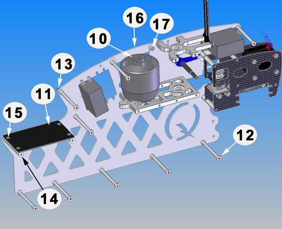
22 2-6 MOTOR MOUNT ASSEMBLY No. Bag# Description Qty No. Bag# Description Qty 1***** Motor 1 5 HB M4x12 Cap Head Bolt** 4 2 Fram Motor Mount 1 6***** HB M3x5 Set Screw 1 3 HB M3x6 Cap Head Bolt* 2 7 Frame Motor Mount Spacer 1 4***** Pinion 1 *For Little Sweetie 10 only. These screws may be M3x6 Flat Head Bolt. **Little Sweetie 10 use M4x6 Cap Head Bolts Note: it is very important to use a Dial Indicator to check the run out of the Pinion Gear shaft. Most of the vibration problems come from this. The run out should be no more than inch (0.06 mm.) For Little Sweetie 10, use two M3x6 Cap Head Bolts (or M3x6 Flat Head Bolts) to mount the Motor Mount Spacer to the motor first. Then use four M4x6 Cap Head Bolts to mount the Motor Mount to the Motor Mount Spacer. For Sweet 16V2, use only four M4x12 to mount them together directly. Page 22 of 69

23 2-7 MAIN GEAR ASSEMBLY No. Bag# Description Qty 1 2 Main Gear Main Gear Hub* 1 3 HB M3x 6 Cap Head Bolt 4 *Sport version is shown on the drawing. Pro version may look a little bit differently. Page 23 of 69

24 2-8 RIGHT SIDE SUBASSEMBLY No. Bag# Description Qty No. Bag# Description Qty 1 Main Frame from step HB M3x8 Cap Head Bolt 18 2 Rear Frame from step x48 Half Round Cross Member x24mm Cross Member 4 15 HB M3x6 Philip Screw Flat Head x10mm Cross Member 4 16 Frame Motor Frame Doubler 1 5 HB M3x18 Cap Head Bolt 5 17 HB M3 Locknut Main Shaft Bearing Block 1 18 Main Gear Assy (Step 2-7) 1 7 Frame Anti-rotation Guide Lower Main Shaft Collar* x16x5 Regular Bearing Main Shaft 1 9 HB M3x6 Cap Head Bolt Upper Main Shaft Collar 1 10 Motor Mount Assy (Step 2-6) 1 22 HB M3x5 Set Screw 4 11 Frame Radio Tray 1 23 Frame Frame Angle x48 Cross Member Main Shaft Sleeve* 1 * Sport version does not have these parts Page 24 of 69

25 Page 25 of 69

26 Sometime the Radio Tray is a little bit wider than the 48 mm Cross Members. You may need to sand it on either side. The four holes in the Radio Tray may be counter sunk for nicer finish. Slide the Main Gear Assembly in, insert the Main Shaft through the Main Shaft Bearing Blocks. Then secure the Gear with one M3x18 Cap Head Bolt and one M3 Locknut. For Pro version, put the Lower Main Shaft Collar on first before securing it. Put the Upper Main Shaft Collar on, and then secure it with four M3x5 Set Screws. Page 26 of 69

27 Page 27 of 69

28 Page 28 of 69

29 2-9 FRAME INSTALLATION No. Bag# Description Qty No. Bag# Description Qty 1 Right Side Subassembly from Step Left Aileron Control Lever 1 2 Left Side Assembly from Step HB M3x7 Pivot Ball Stud Motor Frame Doubler 1 10 HB M3x16 Cap Head Bolt x10mm Cross Member Frame Angle 1 5 HB M3x18 Cap Head Bolt 4 12 HB M3x5x3 Spacer 2 6 HB M3x8 Cap Head Bolt 18 HB M3x4 Pivot Ball Stud 1 7 HB M3 Locknut 1 Attach the Left Side Assembly and the Right Side Assembly together; secure them with Cap Head Bolts and Locknuts. Adjust the Tail Transmission and Start Shaft Bearing Block to get proper gear matches. Trick: fold a piece of tablet paper of 20x100mm (1x4 inch) along a long side and then insert it between the gears. Bring the gears together. Tighten the screws on the Tail Transmission/Start Shaft Bearing Block up and take the piece of paper off. Page 29 of 69


30 2-10 LANDING GEAR INSTALLATION Bag 2-10 No. Bag# Description Qty No. Bag# Description Qty Landing Gear Strut 2 5***** 2-10 CA Glue Landing Gear Skid M3x12 Cap Head Bolt Landing Gear End Cap M3 Locknut M2.5x6 Self Tapping Screws 4 Drill 4 holes in the Landing Gear Struts with a 3mm drill bit with a spacing of 63.5mm Install the Landing Gear Skids into the Struts. Apply CA Glue into the Landing Gear End Cap then insert them into the Skids. Drill four 2.5mm holes into the little rounds on the ends of the Struts then secure them with the four M2.5x6 Phillips Screws. Page 30 of 69

31 Install the Main Frames onto the Landing Gear Assembly and secure them with four M3x12 Cap Head Bolts. Note: It is recommended to use Landing Gear Dampener to reduce vibration. See Other Hardware & Optional Accessories to make order. Landing Gear Dampener is installed between the Landing Gear and the Landing Supports. Page 31 of 69


32 SECTION 3: TAIL ASSEMBLY Bag TAIL PULLEY GEAR SUBASSEMBLY No. Bag# Description Qty 1 3 Tail Output Shaft 1 2 HB M3x5 Set Screw Tail Pulley Gear Tail Gear Side Plate 1 Page 32 of 69


33 3-2 TAIL ROTOR SUBASSEMBLY No. Bag# Description Qty No. Bag# Description Qty 1 3 Tail Case Side Plate M2.3 Medium Ball Link Tail Pitch Lever Mount Tail Pitch Slider X11X4 Bearing Tail Pitch Control Lever 1 4 HB M2x6 Phillips Screw 2 13 HB M3x5x1 Spacer 4 5 In Box Tail Boom 1 14 HB M3x16 Cap Head Bolt 1 6 In Box Timing Belt 1 15 HB M3 Locknut 1 7 HB M3x6 Cap Head Bolt Tail Pulley Gear Subassy Tail Case Cross Member 1 17 HB M2.5x6 Cap Head Bolt 1 9 HB M3x4 Pivot Ball Stud 2 18 HB M3x7 Flat Washer 1 First, to prevent the Boom End from rotating, drill a 2.5mm hole in the side of the Boom End, then secure with an M2.5x6 Cap Head Bolt. Install the Bearings into the Tail Case Side Plates. The flanges should be inside. Page 33 of 69

34 Note: Put three M3x5x1 Spacers between the Left Tail Case Side Plate and the Boom End and Tail Cross Member. If your Tail Cross Member is long enough (16mm), you do not need the spacer for it. Normally you just need one M3x5x1 Spacer between the Tail Pitch Control Lever and Tail Pitch Lever Mount but you may need two of them in some cases (if you do not have enough clearance for the lever.) Page 34 of 69

35 3-3 TAIL ROTOR INSTALLATION No. Bag# Description Qty No. Bag# Description Qty 1 3 Dual Bearing Tail Rotor Vertical Fin Mount B** 1 2 HB M3x20 Cap Head Bolt 2 11 Tail Rotor Subassembly Tail Blade Horizontal Fin Tail Blade Spacer Vertical Fin** 1 5 HB M2x8 Phillips Screw 2 14 HB M3 Locknut** 4 6 HB Shim Ball Horizontal Fin Mount 1 7 HB M3x10 Cap Head Bolt* 2 16 HB M3x30 Cap Head Bolt** 2 8 HB M3x5 Set Screw 1 18***** 3 Electric Tape Vertical Fin Mount A** 1 Carbon Fin Set is also available for option. *Little Sweetie 10 uses two M3x16 Cap Head Bolts. Wrap the electric tape around the boom couple rounds before you install the fins. **Sometimes for the Vertical Fin Set, you may have one piece of Vertical Fin Mount and one Vertical Fin molded with other mount. It works same as the other but the way you install is a little bit different (see figure b). The Cap Head Bolt for this version should be M3x16; the Locknuts are not needed. Page 35 of 69


36 After installing all the parts as shown above, slide this subassembly on the output shaft then secure it with one M3x5 Set Screw. Now put the Ball Links on the Shim Balls. Page 36 of 69

37 Page 37 of 69

38 3-4 INSTALLATION OF THE TAIL No. Bag# Description Qty No. Bag# Description Qty 1 Tail Assembly 1 5 HB M3x10 Cap Head Bolt 2 2 In Box Boom Support 2 6 HB M3 Locknut Boom Support End 4 7***** CA Glue 1 4 HB M3x8 Cap Head Bolt 2 Note for installing the timing belt: Turn the Tail assembly so that the Tail Output Shaft pointing upward put the belt onto the Transmission, then twist the Tail Assembly 90 o to the right. Make sure the belt not too tight or loose. Tighten four locknuts. Measure the Boom Support carefully before cutting. It is a good idea if you install one end of the rod first, then make the measure then cut it. Remember apply CA Glue for the rods when installing into the Support Ends. Page 38 of 69

39 SECTION 4: CONTROL SYSTEM Bag SWASHPLATE ASSEMBLY No. Bag# Description Qty 1 4 Swashplate Complete 1 2 HB M3x7Pivot Ball Stud 6 3 HB M3x 7Flat Washer 4 4 HB M2X4 Phillips Screws Anti-rotation Pin 1 Page 39 of 69

40 4-2 WASHOUT ASSEMBLY No. Bag # Description Qty No. Bag # Description Qty 1 4 Washout Base M3x5 Set Screw Washout Arm 2 6 HB M3x7Pivot Ball Stud Washout Link 2 7 HB M3x10 Cap Head Bolt Washout Link Pin 2 8 HB M3X5X1 Spacer 2 Page 40 of 69
 1 4 4 Washout Anti-rotation Base* 1 5 4/5 Washout Anti-Rot Guide Pin** 1 6 HB M3x5 Set Screw* 1 *Sweet")
41 4-3 CONTROL SYSTEM INSTALLATION No. Bag# Description Qty 1 Swashplate Assembly 1 2 Washout Assembly 1 3 Helicopter (up to step 3) Washout Anti-rotation Base* 1 5 4/5 Washout Anti-Rot Guide Pin** 1 6 HB M3x5 Set Screw* 1 *Sweet 16V2 does not need these parts because Washout Anti-rotation Base is built in the Center Hub. **Sweet 16V2 need two Washout Anti-rotation Guide Pins (see Section 5-B-2). Note: Do not tighten the Set Screw too tight; wait until you put the Head on. Connect two Washout Links to the M3x7 Pivot Ball Studs. For the Little Sweetie 10, the gap between the Head and the Washout Anti-rotation Base will be about 2 mm and the Pin will be almost line up with one of the two little gaps of the Head (see Step 5-A-3). Page 41 of 69

42 SECTION 5-A: ROTOR HEAD for Little Quickie 10 Bag 5 Page 42 of 69

43 5-A-1 MAIN ROTOR HUB ASSEMBLY No. Bag# Description Qty No. Bag# Description Qty 1 5 Main Blade Grip* Head Spindle Spacer Pitch Arm* Thrust Bearing Spacer** Center Hub x10x4 Thrust Bearing** Hiller Arm 2 13 HB M3x6 Flange Cap Head Bolt Head Spindle x13x4 Regular Bearing*** Dampener O-Ring 2 15 HB M3x12 Cap Head Bolt 2 7 HB M3x7 Pivot Ball Stud 2 16 HB 5x7x2 Spacer** 2 8 HB M3x8 Cap Head Bolt** 4 17 HB M9x13x1.45 Thrust Bearing Spacer 2 9 HB M3X5X3 Spacer 2 18 HB M2x4 Phillips Screw 4 *Sport version: Pitch Arms is built in the Main Blade Grips so there are no M3x10 Cap Head Bolts. **Sport version does not have these parts. ***Sport version: BRG05114R (5x11x4 Regular Bearing.) Note: Remember to apply grease for bearings. Thrust Bearing has 3 parts: two races and bearing. The bigger race should be toward the Center Hub. The smaller race should be toward the blade. Parts may look differently from the ones you have in the kit Page 43 of 69

44 Page 44 of 69


45 5-A-2 FLYBAR & SEESAW ASSEMBLY No. Bag# Description Qty No. Bag# Description Qty 1 5 Seesaw 1 8 In 3mm Standard Seesaw Collar 2 9 HB M4x4 Set 2 3 HB M3x8 Cap Head Bolt 4 10 HB 3mm Fly-Bar 2 4 HB M3x7 Pivot Ball Stud x10 Linkage Flybar Spacer 2 12 Main Rotor Hub Fly-Bar Control Arm 2 13 HB M3 Flat Washer Fly-Bar Control Arm Short Ball End 4 15 ***** Epoxy Glue/JP 1 Screw two Short Ball Ends until they hit each other. There are two holes in the paddles. For regular setup, use the hole that is further from the letter Quick on the paddles. Although the drawing does not show the other side of the head, you should repeat the same assembly for that side. Fly-bar should be balanced on the Seesaw. Warning: To prevent the Flybar Paddle from falling off the Flybar, make sure to apply Epoxy Glue/JP Weld to the thread on Flybar after Radio Setup. Page 45 of 69
 1 3 HB M3x20 Cap Head Bolt 1 4 HB M3 Locknut 1 Install the Head")
46 5-A-3 ROTOR HEAD INSTALLATION No. Bag# Description Qty 1 Fly-Bar Seesaw Assembly 1 2 Helicopter (up to step 4) 1 3 HB M3x20 Cap Head Bolt 1 4 HB M3 Locknut 1 Install the Head Assembly into the Main Shaft, and then secure it by one M3x20 Cap Head Bolt and one M3 Locknut. Page 46 of 69
 2 12 5 8x16x5 Thrust")
47 SECTION 5-B: ROTOR HEAD for Sweet 16v2 Bag 5 5-B-1 MAIN ROTOR HUB ASSEMBLY No. Bag# Description Qty No. Bag# Description Qty 1 5 Main Blade Grip 2 9 HB M3X5X3 Spacer Pitch Arm* Head Spindle Spacer Center Hub Thrust Bearing Spacer Hiller Arm ( ** ) x16x5 Thrust Bearing Head Spindle M4x8 Flange Cap Head Bolt Dampener O-Ring x16x5 Regular Bearing 4 7 HB M3x7 Pivot Ball Stud 2 15 HB M3x12 Cap Head Bolt 2 8 HB M3x10 Cap Head Bolt* 4 *Sport version: Pitch Arms is built in the Main Blade Grips so there is no M3x10 Cap Head Bolts ( ** ) You may have different version of the Hiller Arm. It works the same; please see the figure for installation Note: Some Center Hubs are designed for one O-ring each side. If this is your case, use one O-ring each side. The beveled edge of the Thrust Bearing Spacer (No. 11) should be face away from the Center Hub. The flanges of the bearings of the Hiller Arms should face outside. Usually the Thrust Bearing has three parts: two race washers and caged ball bearings. The caged ball bearings will be between two race washers. In some cases, you may get different version of the Thrust Bearing: one race washer, one flat washer, and caged ball bearings in your kit. That is fine; it still works the same. In this case, you need to install the flat washer first (next to Thrust Bearing Spacer-No. 11), then the caged ball bearings, the race washer goes last. Remember to apply grease for bearings. Page 47 of 69

48 5-B-2 FLYBAR & SEESAW ASSEMBLY No. Bag# Description Qty No. Bag# Description Qty 1 5 Seesaw 1 9 HB M3x5 Set Screw Seesaw Collar mm Fly-Bar Paddle 2 3 HB M3x8 Cap Head Bolt Short Ball End 4 4 HB M3x7 Pivot Ball Stud 2 12 Main Rotor Hub Assembly 1 5 HB M4x6x1 Spacer 4 13 HB M3 Flat Washer Fly-Bar Control Arm A mm Linkage Rod Fly-Bar Control Arm B Washout Anti-rotation Pin 2 8 In box 4mm Standard Flybar 1 16 ***** Epoxy Glue/JP Weld 1 There are two holes in the paddles. For regular setup, use the hole that is further from the letter Quick on the paddles. Although the drawing does not show the other side of the head, you should repeat the same assembly for that side. Fly-bar should be balanced on the Seesaw. Connect the Short Ball Ends to the cooperated ball of the Hiller Arms. Make sure to apply Epoxy Glue/JP Weld to the thread on Flybar and the Flybar Paddle (after you finish the Setup) Note: The Center Hub and Flybar Control Arm shown may look differently from the ones in the kit. Page 48 of 69
 1 3 HB")
49 5-B-3 ROTOR HEAD INSTALLATION No. Bag# Description Qty 1 Fly-Bar Seesaw Assembly 1 2 Helicopter (up to step 4) 1 3 HB M3x20 Cap Head Bolt 1 4 HB M3 Locknut 1 Page 49 of 69
 1 2 6 Rudder Push Rod End 2 3***** Electric Tape 1 4 6 Rudder Pushrod Guide 2 5 6 Rudder Pushrod Guide Insert 2 6 HB Shim Ball 1 7 HB M2x8")
50 SECTION 6: LINKAGES Bag RUDDER PUSH ROD INSTALLATION No. Bag# Description Qty 1 In box Rudder Push Rod (in Box) Rudder Push Rod End 2 3***** Electric Tape Rudder Pushrod Guide Rudder Pushrod Guide Insert 2 6 HB Shim Ball 1 7 HB M2x8 Phillips Screw 1 8***** Servo Arm 1 9***** M3 Servo Phillips Screw Long Ball End 2 11***** CA Glue 1.The length of the Rudder Rod measured from center to center should be around 533 mm for Little Sweetie 10 and 554mm for Sweet 16V2..Put electric tape around the Boom before installing the Rudder Push Guide in, so you can remove them later. Page 50 of 69


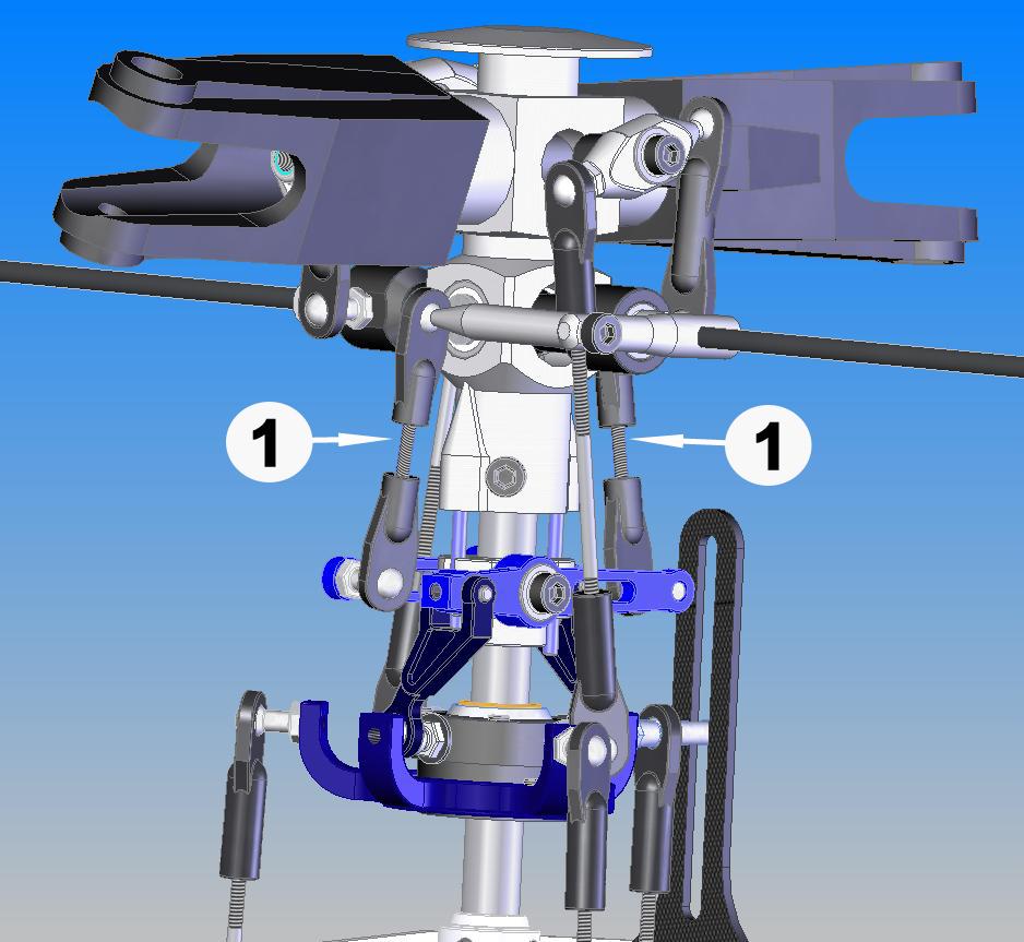
51 6-2 LINKAGE ASSEMBLY No. Bag# Description Qty Long Ball End Medium Ball End x25mm Rod x35mm Rod x45mm Rod x50mm Rod x80mm Rod x100mm Rod 2 Coding the Rod Assembly: All the Linkage should be assembled with dimensions measured center to center and coded as followings: No. Rod Description Link Ball End used Center to Center Qty 1 2.3x25mm Rod Medium 42 mm x35mm Rod Long 58 mm x45mm Rod Long 70 mm x50mm Rod Long 82 mm x80mm Rod Long 105 mm x100mm Rod Long 127 mm 2 The lengths of linkages are used for reference only. Final adjustments might need to be made after setup. Note: Look close to a ball end; you will see one side is different from the other. One has a round marked on it. The other is just plain. When installing a ball link into a pivot ball stud (or a shim ball) the side with a round should face away from a ball stud (or shim ball.) Page 51 of 69

52 6-3 LINKAGE INSTALLATION No. Description Qty No. Bag# Description Qty 1 2.3x25mm Rod Assembly 2 7 Helicopter (up to step 6-1) x35mm Rod Assembly 3 8***** Servo Arm x45mm Rod Assembly 2 9 HB Shim Ball x50mm Rod Assembly 2 10 HB M2x8 Phillips Screw x80mm Rod Assembly 2 11***** M3 Servo Phillips Screw x100mm Rod Assembly 2 Page 52 of 69

53 Page 53 of 69

54 Page 54 of 69

55 Page 55 of 69
 1 2***** Main Blade 2 3***** Main Blade Washer 4 4 HB M4x30 Cap Head Bolt* 2 5 HB M4 Locknut* 2 *Little Sweetie 10 uses M3x22 Cap Head Bolt and M3")
56 SECTION 7: SETTINGS Bag MAIN BLADE INSTALLATION No. Bag# Description Qty 1 Helicopter (up to step 6) 1 2***** Main Blade 2 3***** Main Blade Washer 4 4 HB M4x30 Cap Head Bolt* 2 5 HB M4 Locknut* 2 *Little Sweetie 10 uses M3x22 Cap Head Bolt and M3 Locknut 7-2 SETTING UP RADIO No. Description Qty 1 Helicopter (up to step 7-1) 1 2***** Radio 1 3***** Receiver 1 4***** Gyro 1 5***** Speed Controller 1 6***** Battery for Receiver 1 7***** Main Battery *** 8***** Battery Connector 1 Before setting up the radio, you have to install the receiver, gyro, speed controller, and batteries for your helicopter. See your radio, receiver, speed controller, and gyro manuals for how to hook up. Instead of giving you the exact length of each linkage rod we will explain to you what you are trying to achieve. This is the same for all Quick helicopters. Another thing worth mentioning is that all controls on our helicopters are leading edge controlled. We have Page 56 of 69

57 three such controls on our helicopter and they are Main blades, Tail blade and flybar control arms. For example the main blade pitch arms should be mounted so they are in front of the blades in the direction of travel, clockwise if you look at the helicopter from above, see picture 4. Your radio manual will be needed during this set up. First, set your radio so that all travel values are at 100%. If you have a radio with Swash Mixing set, set those values to 50% (Aileron, Elevator, and Pitch.) Then use servo reversing so that all servos are moving in the right direction. If Pitch operates reversed, change the value in the Swash Mixing from + to -. Step 1: First set your radio up so that all servos are moving in the right direction and adjust all travel values to 100%. If you have a radio with Swash mixing values set those to 50% (Pitch, Aileron and Elevator). Now center both radio sticks (including throttle ) and center all trim and sub-trim values. When this is done turn your receiver pack on. Now mount the servo arms at a 90 o angle towards the linkage rod. In our non push pull helis this will be horizontal. Use the mounting position on the servo arm that will be closest to 90 o, not all servos will line up 100% correct. If they are visible off from the 90 o position the use the sub-trim function in your radio for fine tuning, do not use regular trim for this, see picture 1. Page 57 of 69
 stick all the way down, see picture 2.")
 travel. During such travel, portions of the Swashplate will move below the Swashplate position archived during Pitch full down radio stick position.")
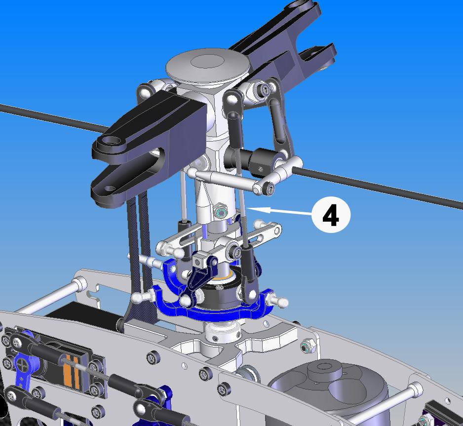
58 Now you have a good start and the rest of the setup will become easier. Step 2: Connecting the Swashplate at the right distance. This is done by moving your Pitch (throttle) stick all the way down, see picture 2. When the servos are in this position adjust the length of the linkage rods so the Swashplate is located towards the bottom, but still leaves enough room for left/right (aileron) and front/back (elevator) travel. During such travel, portions of the Swashplate will move below the Swashplate position archived during Pitch full down radio stick position. So make sure you leave enough room for this extra travel, see picture 2 for recommended height. Also make sure that all 3 linkage rods between the servo arms and the Swashplate are the same, so the Swashplate is level. It should not tilt in any direction; unless your right radio stick is moved. If it lilts, and all linage rods are the same length, then go back to step one and make sure your three servo arms have the same neutral position (horizontal on non push pull helis). Picture 1, Swash center Picture 2, Swash Down Step 3: Connecting the Washout assembly. Connect the fixed length plastic A arms to the Swashplate, connect to the two longer pivot studs, if all four are the same length then any two will do. The next step is to adjust the length of the linkage rod between the Washout Arm and the Flybar connection point. Turn your radio and receiver back on and center both sticks. Now adjust the length of the flybar linkage so the washout arms are level (horizontal), see picture 1. Also make sure your flybar arms and flybar-paddles are level (horizontal), when adjusting the linkage. After the length is adjusted make sure that you have free travel in all directions and stick positions. When the Pitch stick is all the way up it should look like picture 3. As you can see there is still plenty of room for aileron and elevator travel. Now adjust the Washout Anti-rotation pin height so the pin is still in the guide slot of the washout base during all travel positions. For the Left/Right Washout Anti-rotation position, line the attachment point of the plastic washout A arm on the Swashplate up with flybar linkage connection point. The imaginary line between these points should be vertical. Now you are almost done, only one set of links left, and the length of those links will be depending on your desired setup whether it's Aerobatic or normal flying. Please refer to the Pith travel setup table for this final link length. Page 58 of 69


59 Picture 3, Swash Up Picture 4, Head Picture 5, Tail Center Picture 6, Tail Positive Thrust Page 59 of 69
 +10 o +10 o Center (50%) +5 o +0 o Down (0%) -3 o -10 o Collective")
 100% 100% 85% 85% Center (50%) 70% 60% 75% 75% Down (0%) 10% 100% 0% 85%")
60 Picture 7, Tail Negative Thrust Picture 8, Tail Pitch Travel Setup Collective Position Normal Flying Aerobatic Up (100%) +10 o +10 o Center (50%) +5 o +0 o Down (0%) -3 o -10 o Collective Position Throttle Curve Setup Normal Flying Fuel Aerobatic Electric (non governor mode) Normal Flying Up (100%) 100% 100% 85% 85% Center (50%) 70% 60% 75% 75% Down (0%) 10% 100% 0% 85% Aerobatic Page 60 of 69
61 First adjust the servo arm position like you did with the swash, make sure your trim and sub-trim values are centered. Attach the servo arm so it's 90 o to the tail pushrod (vertical). Now adjust your two plastic ball ends, for the push rod, so they are screwed on about half way onto the threaded pushrod guide end piece. This will allow you have maximum amount of adjustment available in both directions. Use the outer holes on the tail blade grips for the ball link attachments. When this is done cut the carbon pushrod to a length that will achieve about 3 o of positive pith on your tail blades, when the servo is in its neutral (vertical) position. Then glue the two end pieces on to the pushrod with CA glue, don't forget to insert the pushrod guides first. When this is done you should have 3 o of positive tail blade pitch. The tail should spin counter clockwise looking at the right side of the helicopter with the nose to your right and tail to your left. See pictures 5-8. Note: Please consult the instruction for your Gyro for setting the overall travel and limits to ensure proper operation and travel of Tail Pitch Slider. The throttle cure will be affected by several conditions; some of them are, motor choice, blades choice, elevation, temperature, helicopter weight and type of helicopter. So in order to explain this I will explain what you are looking for. Your goal is to achieve a constant head speed once the helicopter is airborne. If you ad pitch (climb) you need to ad power (throttle) to compensate for the added resistance a higher blade pitch creates. If during climb your head speed drops, then you need to add throttle to that particular stick position, and reversed if you have an increase in rpm. If during max climb out you experience an increase in head speed then you need to give the blades a higher pitch, do not try to adjust the max climb rpm by reducing throttle. There are other ways of achieving this by using cyclic mixing, however we will stay away from this for now. Follow the pitch guidelines in the table above, and if you need more pitch at max power because the rpm is increasing, then add pitch. 10 o is just a guideline and will work in most setups, but a powerful motor or a light helicopter might need more. For rpm adjustment during anything other than full stick deflection you should use the throttle. A short recap, adjust throttle to adjust rpm during anything other than full collective. At full collective adjust the pitch. See the Throttle table for general setup. These are guidelines and will get you going but might not be 100% accurate in regards to all helicopters. Especially the throttle curve table should be considered as initial guidelines. As mentioned before it's greatly affected by your equipment. As you become more familiar and proficient with your helicopter you can change the pitch and throttle curves to your flying style. Page 61 of 69
 1 2 In box Canopy (in box) 1 3 6 Canopy Stand-off 4 4 6 Canopy Grommet 4 5 HB M3x6 Cap Head Bolt 4 6 HB M3x12 Cap Head Bolt 4 Install the 4 Canopy")
62 7-3 MOUNTING CANOPY No. Bag# Description Qty 1 Helicopter (up to step 7-2) 1 2 In box Canopy (in box) Canopy Stand-off Canopy Grommet 4 5 HB M3x6 Cap Head Bolt 4 6 HB M3x12 Cap Head Bolt 4 Install the 4 Canopy Standoff using 4 M3x6 Cap Head Bolts. Put the Canopy on the helicopter, mark the right positions for 4 holes, and then drill four 5.5mm holes. Install the Canopy Grommets on the Canopy. Secure the Canopy by 4 M3x12 Cap Head Bolts. Page 62 of 69
63 FRE-FLIGHT CHECKS The rotor flybar and shaft must be straight. The flybar and control paddles must tilt in the proper direction and operates smoothly throughout the whole range. Check the swashplate to make sure it move smoothly and clean. When control input are given to tilt the swashplate, make sure no control arms or pushrods are binding. Check the two control paddles for level, parallel, and proper direction. Make sure the batteries are fully charged. Make sure the radio and receiver are on and all controls operate properly before flight. There should be no interference of radio signal in your flying zone. Range check the radio. Always grab onto the helicopter main rotor head when turning on the helicopter. WARNINGS Do not operate helicopters in rainy, windy, or snowy condition. Operate helicopter in a safe zone away from crowds, traffic, or distractions. Use the proper batteries to prevent damage to the motor and equipment. Make sure all the batteries are fully and properly charged. Make sure all the controls operate properly before flight. The main and tail rotors blades operate at very high speed (rpm); therefore, make sure nothing can come into contact with them while they are spinning. Perform a range check on the radio before flying. Make sure the transmitter and receiver are turned on before plugging in the main power battery/batteries. Keep a safe distance when operating a helicopter. Do not fly for a long period of time. Take some rests during flights. Motors are often very hot after operation. So be careful when handling or touching them immediately after flying. Page 63 of 69
64 ADJUSTMENTS Tracking Adjustment: The tips of the main rotor blades should follow the same path when they rotate. We call the main rotor blades are in track. (a) Rev up the motor until the helicopter becomes light on its landing gear. Raise throttle gently and gradually (b) If the main rotor blades are in track, it s good. (c) If the blades are out of track, then adjust one of the pushrods that connect to the main rotor blade pitch arm. Out of track Repeat steps (a) to (c) until the blades are in track. Trimming: Most of new built helicopters are unstable. But if you trim your helicopter properly, you will stop it from drifting away or yawing by itself quickly. Followings are instructions for trimming your helicopter. (a) If the helicopter nose starts to yaw left or right, adjust the tail rotor push rod to compensate. If using a Heading Hold Gyro, do not adjust the trim lever on the radio. (b) If the helicopter rolls to left or right, then: Page 64 of 69
65 Rolls to the left, move the button to R Rolls to the right, move the button to L L R (c) If the helicopter nose goes down or up, then: Goes up, move the stick to U Goes down, move the stick to D U D HOW TO HOVER Basic maneuver for a pilot is learning how to hover a helicopter. When the helicopter is floating in a stationary position in the air, we call that hovering. Use the following procedure to practice your hovering: (a) Make sure everything is clear in the flying zone. Stand at least 30 feet (10 meters) behind the helicopter. (b) Check the main rotor fore/aft and left/right cyclic to make sure the main rotor is following to your cyclic command before taking off. Make sure the helicopter nose will swing in your desired directions by moving the tail rotor control stick. (c) Now, increase the throttle/collective gently to lift the helicopter landing gear off the ground to no more than 4 inches (10 cm). At the beginning, it is very difficult for the Page 65 of 69
66 pilot to keep the helicopter from moving. It will also be difficult to know if the helicopter is in trim or not for a beginner. Keep going on the practice close to ground you will develop your skills. (d) Keep practicing lifting your helicopter no more than 8 inches (20cm) from the ground until you feel comfortable with control commands. Once you can keep it at one place, then it is time to slowly increase the height a few inches in each fight. Soon, you will be able to hover the helicopter confidently at a few feet high. Beginners should always practice hovering close to ground since in an emergency situation; you can drop the throttle and collective quickly without making any big damage. 4 ~ 8 inches (e) Stand behind the helicopter so you can watch the nose of the helicopter. A left tail rotor command will yaw the helicopter nose to the left, and a right command will yaw to the right. Also, a left cyclic command will cause the helicopter to translate left., Start practice hovering while standing to either side of the model after you can comfortably hover the helicopter at 3 feet (1m) high without drifting. Finally, you need to learn hovering the model from any positions. When you can confidently hover a helicopter at any altitude and at any position, you have mastered most of the fundamental control movements of a helicopter. Page 66 of 69
 above the ground.")
67 HOW TO FLY FORWARD Once you have mastered hovering fight: (a) Let s begin the exercise of changing positions by practice moving the helicopter to the left or right slowly from 60 inches (1.5 m) above the ground. Hovering at 60 inches Page 67 of 69
68 (b) Once you have been comfortable with all the movements and controls in the previous step, start using some tail rotor control to make the helicopter point slightly to the left or right as you fly it to the left or right. Keep practicing the figure-eight path as shown below, you will master all basic control movements of a helicopter. Page 68 of 69
69 AFTER FLIGHT CHECKS After each flight, the helicopter should be thoroughly inspected: (a) Unplug the batteries. (b) Check every bolt, nut, and screw to make sure none has loosened due to vibration. (c) Check every rotating and movable part like head rotor, swashplate, tail rotor to ensure they still move smoothly and properly. (d) Check all movable parts, such as gears, ball links, belt, etc. for unusual wear. (e) Clean up the helicopter then lubricate every moving part with oil to ensure a smooth operation in the future. (f) Keep the helicopter in a cool and dry place. Avoid storage under direct sun light or near heat. (g) Please replace any damaged parts if they are discovered during maintenance. WHAT IF THE HELICOPTER CRASHED Turn off everything and check the helicopter immediately. If any item is damaged, replace the damaged parts to ensure safe operation. Do not try to glue any broken or damaged plastic or carbon parts specially broken rotor blades. The followings are parts that should be inspected right away: Main and tail rotor blades. Flybar, main shaft, head spindle, and tail output shaft. All the gears. Tail boom and supports for cracks. Vertical and horizontal fins. Frames. All pushrods. Servos, motor, and batteries. SPECIFICATION Specification Little Sweetie 10 Sweet 16V2 Blades Quick mm Quick mm Length 890 mm (35 inch) 1000 mm (39.4 inch) Height mm (13 inch) 355 mm (14 inch) Weight ~3.8 lbs(1.7 kg) ~4.0 lbs (1.8 kg) Batteries Li-Po 4S4P Li-Po 4S3P x 2 Motor Aveox 36/30/2 - Axi 4120/14 Frame Thickness mm mm Spindle 5mm 8mm Main Shaft 8mm 8mm Canopy Fiberglass Fiberglass Flying Aerobatic / 3D Aerobatic / 3D Page 69 of 69
TABLE OF CONTENTS INTRODUCTION 3 CUSTOMER SERVICE 4 FEATURES 5 FRE-ASSEMBLY INFORMATION 6 REQUIRED TOOLS 7 HARDWARE & OPTIONAL ACCESSORIES 8
 Page 1 of 84 TABLE OF CONTENTS INTRODUCTION 3 CUSTOMER SERVICE 4 FEATURES 5 FRE-ASSEMBLY INFORMATION 6 REQUIRED TOOLS 7 HARDWARE & OPTIONAL ACCESSORIES 8 OTHER HARDWARE & OPTIONAL ACCESSORIES 9 OTHER REQUIREMENTS
Sport/Pro HELICOPTER First Edition
 Sport/Pro HELICOPTER First Edition ASSEMBLY AND MAINTENANCE MANUAL WWW.QUICKHELI.COM Page 1 of 60 TABLE OF CONTENTS INTRODUCTION 3 CUSTOMER SERVICE 4 FEATURES 5 PRE-ASSEMBLY INFORMATION 6 REQUIRED TOOLS
The Quick Fly. Page 1 of 69
 The Quick Fly Page 1 of 69 TABLE OF CONTENTS INTRODUCTION 3 CUSTOMER SERVICE 4 FEATURES 5 FRE-ASSEMBLY INFORMATION 6 REQUIRED TOOLS 7 HARDWARE & OPTIONAL ACCESSORIES 8 OTHER HARDWARE & OPTIONAL ACCESSORIES
Specifications ASSEMBLY INSTRUCTIONS
 ASSEMBLY INSTRUCTIONS Specifications Length : 6 mm Height : 218 mm Main Blade : 325 mm Main Rotor Diameter : 723 mm Tail Rotor Diameter : 150 mm Motor Pinion Gear : 16T (14T) Main Drive Gear : 150T Main
Hawk Sport. Quick Build Guide. Century Helicopter Products. Designed and Developed in USA
 Hawk Sport Quick Build Guide This Century HAWK SPORT kit comes in a QUICK BUILD format that has most of the major systems already assembled into sub-assemblies. These are packed seperately into their specific
It has taken a while to get
 HOVERING15 99 15 BASICS HOVERING Hovering It has taken a while to get here, but this is what all the building and planning were for to see light under those skids. But this is also the time when you have
Instruction Manual book
 book ITEM CODE:BH 115. SPECIFICATION Wingspan : 6,000 mm 236,22 in. Length : 2,740 mm 107,87 in. Weight : 17.5kg 38.5Lbs. Radio : 08 channels. Servo : 07-08 HS-5685MH(HITEC) Battery : 2 Cells-Li-Po 7.4V
700 scale fuselage MD500 INSTRUCTION MANUAL
 700 scale fuselage MD500 INSTRUCTION MANUAL Produced By: 1 TABLE OF CONTENTS Additional items required. Adhesives and building supplies.. Disclaimer Parts sheet.... Fuselage setup. Installing the mechanics..
450 scale fuselage A109 INSTRUCTION MANUAL. Produced By:
 450 scale fuselage A109 INSTRUCTION MANUAL Produced By: 1 TABLE OF CONTENTS Additional items required. Adhesives and building supplies.. Disclaimer Parts sheet.... Initial setup. Installing the mechanics..
Important Notes Note Recommended Equipment NOT included in kit
 Important Notes This helicopter is recommended for skilled intermediates and advanced RC helicopter flyers. Make sure to read and follow all the instructions in this manual, including all accessories.
AVANT Aurora Ultimate 90
 2 AVANT Aurora Ultimate 90 Assembly Manual AVANT Aurora Ultimate 90 Assembly Manual V1.08 LIABILITY DISCLAIMER This kit is for a radio controlled (RC) helicopter. RC Helicopters are not toys. Moving parts
Assembly instructions
 Assembly instructions Step up to Excellence with X-cell 2 Table of Contents Kit Introduction...4 R/C Helicopter Safety...4 Warning...4 General Guidelines...4 Academy of Model Aeronautics (AMA)...5 Kit
500 scale fuselage Airwolf INSTRUCTION MANUAL. Produced By:
 500 scale fuselage Airwolf INSTRUCTION MANUAL Produced By: 1 TABLE OF CONTENTS Additional items required. Adhesives and building supplies.. Disclaimer Parts sheet.... Initial setup. Installing the mechanics..
8-3 MAIN ROTOR BLADE ATTACHMENT (BLADES NOT INCLUDED)
") 8-3 MAIN ROTOR BLADE ATTACHMENT (BLADES NOT INCLUDED) Two sets required Socket Head Bolt, 4 x 35 mm...2 pcs Hold the 4 mm Lock Nut while tightening using a Wiha 7 mm Nut Driver or equivalent. Lock Nut,
8-3 MAIN ROTOR BLADE ATTACHMENT (BLADES NOT INCLUDED) Two sets required Socket Head Bolt, 4 x 35 mm...2 pcs Hold the 4 mm Lock Nut while tightening using a Wiha 7 mm Nut Driver or equivalent. Lock Nut,
Assembly instructions
 Assembly instructions Step up to Excellence with X-cell 2 Table of Contents Kit Introduction...4 R/C Helicopter Safety...4 Warning...4 General Guidelines...4 Academy of Model Aeronautics (AMA)...5 Kit
Marco Cantoni. joins W3MH from Japan to describe 3D setup for the TSK MyStar series of helicopters. World Wide Web Model Helicopter
 Introduction 3D flying has become very popular in the last few years and is no longer a strange flying style for a few crazy pilots. With the new F3C rules even the most traditional and serious competition
AVANT Aurora Ultimate 90
 2 AVANT Aurora Ultimate 90 Assembly Manual AVANT Aurora Ultimate 90 Assembly Manual V2.00 LIABILITY DISCLAIMER This kit is for a radio controlled (RC) helicopter. RC Helicopters are not toys. Moving parts
ALMOST READY TO FLY. Wing Span in cm. 2
 ASSEMBLY MANUAL ALMOST READY TO FLY MS:X9 Specifications Wing Span --------------------------61.4 in ---------------------------156cm. 2 Wing Area --------------------------606.1 sq.in ------------------
51in Aerobatic Series Sukhoi SU-26M Almost-Ready-to-Fly. Instruction Manual. Specifications
 51in Aerobatic Series Sukhoi SU-26M Almost-Ready-to-Fly Instruction Manual Specifications Wingspan: 51.2 in (1300mm) Length: 51.2 in (1300mm) Wing Area: 581 sq in (37.5sq dm) Flying Weight: 3.5 lb (1600g)
PilotRC Trainer USER MANUAL
 PilotRC Trainer USER MANUAL Introduction Thank you for purchasing our Trainer plane. we strive to achieve a good quality quick build ARF aircraft. It requires the least amount of assembly of any ARF kit
Instruction Manual book
 book Item code:bh131 SPECIFICATION Wingspan : 3,000 mm 118.1 in. Length : 1,600 mm 62.99 in. Weight : 2.2 kg 4.84 Lbs. Radio : 05 channels. Servo : 06 mini servos. Electric Motor: BOOST 40 Battery : 3celIs
3DX 450 ASE V3 COPYRIGHT. CONTENTS 2 Safety Note s 3...Hardware Identification 4...Assembly Instructions 5...Maintenance Main Rotor Assembly
 3DX 450 ASE V3 COPYRIGHT Instruction Manual Author: Per Backman Date: 10/30/2006 CONTENTS 2 Safety Note s 3...Hardware Identification 4...Assembly Instructions 5...Maintenance 6-8...Main Rotor Assembly
Instruction Manual book
 Instruction Manual book ITEM CODE:BH118. SPECIFICATION Wingspan : 1,050 mm 41.34 inches. Length : 950mm 37.4 inches. Weight : 1 kg 2.2 lbs. Radio : 04 channels. Servo : 4 mini servos. Motor : KMS 2814/05
Turbinator-2 Build Manual
 Turbinator-2 Build Manual Thank you for your purchase of the Turbinator-2 sport jet by Boomerang RC Jets. This RC Jet IS NOT A TOY and should only be flown and operated by experienced RC Turbine Pilots.
Instruction Manual SPECIFICATIONS
 Instruction Manual Hummingbird CP Hummingbird FP SPECIFICATIONS Engineered for ultimate performance. Light weight, durable, powerful design featuring CNC machined anodized aluminum heat sink chassis plate,
INSTRUCTION MANUAL WARRANTY
 INSTRUCTION MANUAL Rotor Diameter: 23 in [588mm] Weight: 20.5 23 oz [580 650 g] Length: 25 in [630mm] Height: 9 in [225mm] Motor: 200W brushless, 28mm diameter Heli-Max guarantees this kit to be free from
SKYARTEC MOSQUITO 3D PRO
 SKYARTEC MOSQUITO 3D PRO Instruction & assembly manual Specifications: This micro R/C helicopter has the most advanced capabilities. 120 degree CCPM control, collective main and tail rotors, belt tail
SAFARI Helicopter Flight Control Rigging Manual Revision 9 4/3/2010 CHR International Inc.
 SAFARI Helicopter Flight Control Rigging Manual Revision 9 4/3/2010 CHR International Inc. The following procedures are meant as a guide to assist you in the safe configuration of your helicopter s Flight
Manual LOGO 500 DX LOGO 500 3D LOGO 600 DX LOGO 600 3D.
 Manual LOGO 500 DX LOGO 500 3D LOGO 600 DX LOGO 600 3D www.mikado-heli.de Mikado Modellhubschrauber Friedrich-Klausing-Straße 2 14469 Potsdam Germany phone +49 (0)331 23749-0 fax +49 (0)331 23749-11 www.mikado-heli.de
52 BACKYARDFLYER.COM FLY
 52 BACKYARDFLYER.COM FLY HELIS IN1O EASY STEPS by Klaus Ronge Photography by Hope McCall & Pete Hall Flying model helicopters is exciting and fun and looks very easy, that is, until you try it. Unlike
SOXOS DB7. Words & Pictures: Raquel Bellot
 SOXOS DB7 Words & Pictures: Raquel Bellot The Soxos DB7, Swiss brand Heli Professional's flagship helicopter. Specifically, it started life as a Soxos 700 which was modified and updated by world champion
Pitts Challenger m (100cc) MANUAL
 MANUAL") Pitts Challenger 87 2.20m (100cc) MANUAL 1- Introduction: WELCOME TO THE PILOT-RC TEAM! Thank you for choosing a Pilot-Rc plane as your next model. We hope that you enjoy many successful and exhilarating
Pitts Challenger 87 2.20m (100cc) MANUAL 1- Introduction: WELCOME TO THE PILOT-RC TEAM! Thank you for choosing a Pilot-Rc plane as your next model. We hope that you enjoy many successful and exhilarating
AVIATOR 25 ARF Almost Ready-to-Fly
 AVIATOR 25 ARF Almost Ready-to-Fly Instruction Manual Specifications Wingspan: 54.3 in (1380mm) Length: 45.2 in (1150mm) Wing Area: 438 sq in (34sq dm) Flying Weight: 3.8 b (1700g) Dear Customer, Congratulations
RIGGING THE FLIGHT CONTROLS
 RIGGING THE FLIGHT CONTROLS Rigging refers to the installation and adjustment of the rods that move flight surfaces in response to inputs from the controls of the helicopter. These rods are cut to length,
RECOMMENDED MOTOR AND BATTERY SET UP
 SPECIFICATION - Wingspan: 6000mm (236.2 in) - Length: 2873mm (113.1 in) - Flying weight: 14-18 kg - Wing area: 219.4 dm2 - Wing loading: 64g/dm2 - Wing type: HQ airfoils - Covering type: Genuine ORACOVER
Manual GLOGO
 Manual GLOGO 690 www.mikado-heli.de Mikado Model Helicopters GmbH Graf-von-Schwerin-Str. 40 14469 Potsdam Germany phone +49 (0)331 3749-0 fax +49 (0)331 3749-11 www.mikado-heli.de Mikado Model Helicopters
Build Manual. Vector & Xtra Slick
 Build Manual Vector & Xtra Slick Warning information this is not a toy! Read and understand entire manual before assembling model Do not overlook the warnings and instructions enclosed or those provide
INTRODUCTION CONTENTS WARNING
 INTRODUCTION Congratulations on your purchase of the Raptor 30 V2 helicopter. This model was designed and engineered by the World-renowned Mr. Shigetada Taya. It combines elements of his previously successful
Manual LOGO 550 SE.
 Manual LOGO 550 SE www.mikado-heli.de Mikado Model Helicopters GmbH Friedrich-Klausing-Straße 14469 Potsdam Germany phone +49 (0)331 3749-0 fax +49 (0)331 3749-11 www.mikado-heli.de Mikado Model Helicopters
Aviator Pro 120 ARF. Instruction Manual. Specifications
 Aviator Pro 120 ARF Instruction Manual Specifications Wingspan: 110 in (2800 mm) Length: 74 in (1870 mm) Wing Area: 1581sq in (102 sq dm) Weight: 11.4-13.4 lbs (5190-6100 g) Dear Customer, Congratulations
Instruction Manual BULLDOG. Wingspan : 1410 mm (55.5in) : 1450 mm (57.1in) : 4900gr gr. Weight. : 6-9 Channel/ 7 servo high torque, 1standard
 : 1450 mm (57.1in) : 4900gr gr. Weight. : 6-9 Channel/ 7 servo high torque, 1standard") Wingspan : 1410 mm (55.5in) Length Weight Radio Engine : 1450 mm (57.1in) : 4900gr - 5600gr : 6-9 Channel/ 7 servo high torque, 1standard : 1.20/ 2 stroke 1.80/ 4 stroke KIT CONTENTS: We have organized
Wingspan : 1410 mm (55.5in) Length Weight Radio Engine : 1450 mm (57.1in) : 4900gr - 5600gr : 6-9 Channel/ 7 servo high torque, 1standard : 1.20/ 2 stroke 1.80/ 4 stroke KIT CONTENTS: We have organized
Instruction Manual book
 Instruction Manual book Item code:bh133 SPECIFICATION Wingspan : 1,400 mm 55.12 in. Length : 1,350 mm 53.15 in. Weight : 3.7 kg 8.14 Lbs. Radio : 08-09 channels. Servo : 08-09 servos. EDF : Turingy SK3
64MM F-16 Fighting Falcon V2
 64MM F-16 Fighting Falcon V2 SIMPLE Simple assembly RIGID STRONG DURABLE EPO STABLE SMOOTH FLYING PERFORMANCE FMSMODEL.COM Table of Contents Introductions 3 Contents of Kit 4 Assemble the plane 5 Battery
! IMPORTANT! Twister CP Gold
 SPECIFICATIONS Main rotor diameter 0mm Tail rotor diameter..12mm Length..30mm Weight (without receiver & battery)....390g (11.oz) CONTENTS 1...Assembled helicopter 1 pair.....carbon Fibre main rotor blades
F3D-30 ARF ASSEMBLY MANUAL
 F3D-30 ARF ASSEMBLY MANUAL This Manuel is the sole property of Kangke Industrial USA, Inc. Reproducing any part without the consent of Kangke Industrial USA, Inc. is a lawful violation. Kangke Industrial
40 EP Gee Bee Y Scale ARF V2 Instruction Manual Specs:
 40 EP Gee Bee Y Scale ARF V2 Instruction Manual Specs: Wing Span: 40" Overall length: 30" Wing area: 306 sq. in Ready to fly weight: 28~32 oz Motor/Engine: Electric: Uranus-28309 brushless outrunner motor,
Instruction Manual book
 Instruction Manual book ITEM CODE:BH118. SPECIFICATION Wingspan : 1,050 mm 41.34 inches. Length : 950mm 37.4 inches. Weight : 1 kg 2.2 lbs. Radio : 04 channels. Servo : 4 mini servos. Motor : BL2215/20
Instruction Manual book
 Instruction Manual book ITEM CODE:BH135 SPECIFICATION Wingspan : 4,200mm. 163.35 in. Length : 2,100 mm. 82.68 in. Weight : 7,6 kg. 16.72lbs Radio : 07 channels. Servo : 05 06 standard high torque servos,
48in Sbach-342. Instruction Manual. Specifications
 48in Sbach-342 Instruction Manual Specifications Wingspan: 48in (1219mm) Length: 46in (1163mm) Wing Area: 471sq in (30.4sq dm) Flying Weight: 1.8-2.0lb (800-900g) Dear Customer, www.valuehobby.com/48in-s342-arf.html
MS:159 ASSEMBLY MANUAL. Graphics and specifications may change without notice.
 ASSEMBLY MANUAL MS:159 Graphics and specifications may change without notice. Specifications: Wing span ----------------------------61.8in (157cm). Wing area -----------------1100.5sq.in (71.0sq dm). Weight
LOGO 400 V-Stabi. Manual.
 Manual www.mikado-heli.de LOGO 400 V-Stabi Mikado Modellhubschrauber Friedrich-Klausing-Straße 2 14469 Potsdam Germany Phone +49 (0)331 23749-0 Fax +49 (0)331 23749-11 www.mikado-heli.de Mikado Modellhubschrauber,
Caution Notes. Features. Specifications. Installation. A3 3-axis Gyro & Stabilizer User Manual V1.0
 Caution Notes Thank you for choosing our products. If any difficulties are encountered while setting up or operating it, please consult this manual first. For further help, please don t hesitate to contact
Manual LOGO 600 SE.
 Manual LOGO 600 SE www.mikado-heli.de Mikado Model Helicopters GmbH Friedrich-Klausing-Straße 4469 Potsdam Germany phone +49 (0) 749-0 fax +49 (0) 749- www.mikado-heli.de Mikado Model Helicopters GmbH
VENom night ranger 3D pilot s Handbook. Read Before Flight! VENF
 VENom night ranger 3D pilot s Handbook Read Before Flight! VENF-6225-1 I. Introduction The Venom Night Ranger 3D is a high performance Ready-to-Fly Collective Pitch (CP) Aerobatic Electric Helicopter for
Guide For The FEDA Mini-Helicopter
 Guide For The FEDA Mini-Helicopter Thank you For purchasing Feda model helicopter. This is a mini electric R/C model helicopter that makes indoor flying a practical reality as well as flying outdoor in
INSTRUCTION MANUAL WARRANTY
 INSTRUCTION MANUAL Rotor Diameter: 27.5 in [700mm] Weight: 19 22 oz [580 760g] Length: 25.4 in [645mm] Height: 9 in [225mm] Motor: ElectriFly Ammo 28-45-2700kV (GPMG5215) Heli-Max guarantees this kit to
MiG-29 Retract Kit (for the HET-RC Mini Air Retract System)
") MiG-29 Retract Kit (for the HET-RC Mini Air Retract System) The MiG-29 Retract Kit was designed to allow the easy installation of the HET-RC mini Air Retract system into the twin EDF MiG-29. We recommend
MiG-29 Retract Kit (for the HET-RC Mini Air Retract System) The MiG-29 Retract Kit was designed to allow the easy installation of the HET-RC mini Air Retract system into the twin EDF MiG-29. We recommend
Instruction Manual book
 book ITEM CODE:BH 145 SPECIFICATION Wingspan: 6,000mm 236.22 in. Length : 2,800 mm 110.24 in. Weight : 18.5 kg 40.7 Lbs. Parts listing required (not included). Radio : 07-08 channels. Servo : 09-10 standard
AVIATOR REMOTE CONTROL HELICOPTER
 AVIATOR REMOTE CONTROL HELICOPTER THANK YOU. Thank you for your purchase of Protocol s Aviator Remote Control Helicopter. You are about to experience the best of what remote control flight has to offer.
I n s t r u c t i o n M a n u a l. Instruction Manual SPECIFICATION
 I n s t r u c t i o n M a n u a l Instruction Manual SPECIFICATION - Wingspan: 3200mm (125,9 in) - Length: 1650mm (64,9 in) - Flying weight: 3000gr 3200gr - Wing area: 64.5 dm2 - Wing loading: 46g/dm2
J & D Machine / Hyperdrive / MSA 3711 Moon Bend Rd. Chapel Hill, TN 37034
 J & D Machine / Hyperdrive / MSA 3711 Moon Bend Rd. Chapel Hill, TN 37034 www.hyperdriveracing.com 1 You now own a state of the art 1/10 scale oval race car. The Hyperdrive Assault has gone through months
8mm EPP Acrocub. Instruction Manual. Specifications
 8mm EPP Acrocub Instruction Manual Specifications Wingspan: 34.6 in (880mm) Length: 31.5 in (800mm) Wing Area: 213.9 sq in (13.8sq dm) Flying Weight: Approx. 9oz (270g) Dear Customer, www.valuehobby.com/8mm-epp-acrocub.html
How to use the Multirotor Motor Performance Data Charts
 How to use the Multirotor Motor Performance Data Charts Here at Innov8tive Designs, we spend a lot of time testing all of the motors that we sell, and collect a large amount of data with a variety of propellers.
Instruction Manual. Specification:
 Instruction Manual L O W Specification: Wingspan: 133 cm (52.3 inches) Length : 104 cm (40.9 inches) Weight : 1790gr Engine : 25-32 two stroke Radio : 4 channel - 4 servo W I N G KIT CONTENTS: We have
Assembly Manual. 1/10th Formula 1 Car
 Assembly Manual 1/10th Formula 1 Car Center Pivot Bag 1 3374 - Center Pivot Socket 40194 - Hard Anodized Alum Pivot ball 3254-2-56 *Note - Sometimes it is helpful to slightly over-tighten the top clamp
F3P Instruction Manual
 Before use, please read the explanations carefully! F3P Instruction Manual Specifications Fuselage length: 884mm ( 34. Bin ) Wingspan : 845mm ( 33. 2in) Flying Weight : 135-160g (with battery) Additional
COMPLETE RTF R AIRPLANE
 COMPLETE RTF R AIRPLANE Quiet Electric Flight Radio-Controlled Model Requires 8 (AA) Alkaline Batteries (not included) ASSEMBLE ONLY WITH ADULT SUPERVISION Please read through this instruction booklet
Assembly Manual For. Wingspan: 88 in Wing area: sp in Length: 78.8 in Engine: 50CC.
 Assembly Manual For Wingspan: 88 in Wing area: 1479.8 sp in Length: 78.8 in Engine: 50CC www.pilot-rc.com INTRODUCTION Thank you for purchasing our new 50 cc model. We strive to bring you the most complete
96in Super Decathlon ARF
 96in Super Decathlon ARF Instruction Manual Specifications Wingspan: 96in (2438mm) Length: 63.5 in (1614mm) Weight: Approx. 13lbs (6.5kg) 1 Dear Customer, Congratulations on your purchase of Super Decathlon
V Specification
 V1.0.2 Specification Factory configured CNC torque tube and tail boom assembly. Indexed holes on Main Shaft Bearing Blocks allow precision fit with minimal freeplay. One piece CNC open tail box for maximum
Shown with optional GFR-1017R Body Posts. J & D Machine / Hyperdrive / MSA 3711 Moon Bend Rd. Chapel Hill, TN
 Shown with optional GFR-1017R Body Posts J & D Machine / Hyperdrive / MSA 3711 Moon Bend Rd. Chapel Hill, TN 37034 www.hyperdriveracing.com 1 You now own a state of the art 1/10 scale oval race car. The
Newsletter. New Product Information New Design & Specification Miscellaneous July 10. Availability:
 The very high agility and the maximum power of the Titan X50 is, because of the optimum weight and the great main rotor head perfect. The result is a lot of fun in flying hard 3D. In addition the precision
FLIGHTTEST. The Tiger 50 is all about delivering a HIGH-QUALITY HELI at a cost that s hard to beat.
 FLIGHTTEST The Tiger 50 is all about delivering a HIGH-QUALITY HELI at a cost that s hard to beat. BY MIKE McGEE > PHOTOS BY MIKE McGEE & JIM SPEARS AUDACITY MODELS TIGER 50 Low cost audacious performance!
Ultimate EP. Before commencing assembly, please read these instructions thoroughly. I NSTRUCTI ON M ANUAL. Warning! This model is not a toy.
 I NSTRUCTI ON M ANUAL Before commencing assembly, please read these instructions thoroughly. Ultimate EP (GM05) Specifications Wing Span: 3.5 in / 85 mm Wing Area: 357 sq in / 3 sq dm Flying Weight: 4
FIRE PHOENIX RADIO CONTROLLED AIRPLANE
 FIRE PHOENIX RADIO CONTROLLED AIRPLANE ASSEMBLY AND OPERATION INSTRUCTIONS YIN YAN MODEL TECH. MFT. 1 SPECIFICATIONS Material EPO Plane Battery Li-Po 1300mAh 11.1V Radio 4 Channel Wing Span 1200mm Length
RADIO CONTROL MODEL HURRICANE
 RADIO CONTROL MODEL VQAA040G VQAA040B HURRINE Almost ready to fly SPECIFITIONS Wingspan...63 in. / 161cm Length...50 in. / 129cm Engine...50~60 2T / 70~90 4T Or Electric equivalent. RC Functions: Motor
YAK-54 EXP. 48 inch Electric ARF
 YAK-54 EXP 48 inch Electric ARF 1 Greetings and congratulations on your purchase of the Extreme Flight RC Yak-54 EXP ARF! Like all of the EXP series, the YAK-54 excels at both 3D and precision maneuvers.
INTRODUCTION CONTENTS WARNING
 INTRODUCTION Congratulations on your purchase of the Raptor helicopter. This model was designed and engineered by the World-renowned Mr.Shigetada Taya. It combines elements of his previously successful
ITEMS INCLUDED. 2.4GHz Controller
 READ THESE INSTRUCTIONS BEFORE FLYING! ITEMS INCLUDED.4GHz Controller Flight Battery Charger SKY Cruiser LiPo Flight Battery AA Batteries AC Power Supply WARNINGS FOR YOUR SAFETY PLEASE READ AND UNDERSTAND
Twister 3D Storm The Ultimate 3D Electric Helicopter
 The Ultimate 3D Electric Helicopter SPECIFICATIONS Main rotor diameter 720mm Tail rotor diameter..135mm Length..630mm Weight (without receiver & battery)....500g (17.5oz) CONTENTS 1...Assembled helicopter
FINAL ASSEMBLY GUIDE
 3D-CAPABLE, ELECTRIC-POWERED HELICOPTER FINAL ASSEMBLY GUIDE FEATURES AND SPECIFICATIONS: 90% Factory-Assembled w/balanced Main Rotor Blades The EvoFlight Shogun 400 EP heli is distributed exclusively
Flight Manual. Entire contents Megatech 2009 Rev
 Flight Manual www.megatech.com Entire contents Megatech 2009 Rev. 200909210830 If you have questions about operating or assembling your new Megatech product... Please Call Megatech First! DO NOT RETURN
Climber is 776B101101
 is Climber 776B101101 Introduction Product Introduction NE R/C 776B is a good-sized glider designed by Nine Eagles Company latest, whose wing span is up to 2008mm. You only need to assemble the aerofoil
USER GUIDE - SUPPLEMENTAL
 USER GUIDE - SUPPLEMENTAL CONTENTS 5 Instructions for RX2702V receiver... 2 5.3 Channel connection of receiver... 2 10 Walkera V450D01 Flybarless System Setting RX2702V... 3 10.5 Flybarless system setting...
AXE100 CX Instruction Manual
 NOTICE AXE100 CX Instruction Manual The instruction manual, warranties and other associated documentation are subject to change without notice. Hobbico assumes no responsibility for inadvertent errors
B E L T D R I V E T A I L R O T O R A D A P T E R. DAWSO S APPROACH E GI EERI G Ridgecrest, California
 B E L T D R I V E T A I L R O T O R A D A P T E R DAWSO S Ridgecrest, California 93555 www.approachengineering.com 1.0 Purpose To establish a process that ensures control and standardization in the manufacturing
SU-31 PROFILE ELECTRIC ARF ASSEMBLY MANUAL
 SU-31 PROFILE ELECTRIC ARF ASSEMBLY MANUAL 1 TABLE OF CONTENTS Page Aeroworks Contact Information... 3 Introduction.. 4 Kit Contents... 5 Items needed to complete 6 Wing Assembly. 7 Stab Assembly. 10 Flight
Before commencing assembly, please read these instructions thoroughly.
 I NSTRUCTI ON M ANUAL Before commencing assembly, please read these instructions thoroughly. (GM081XM) Specifications Wing Span: 62.9 in / 1600 mm Wing Area: 428 sq in / 27.6 sq dm Flying Weight: 25.8
(Glider) ASSEMBLY MANUAL
 ASSEMBLY MANUAL") (Glider) MS:132 ASSEMBLY MANUAL Graphics and specifications may change without notice. Specifications: Wing span ------------------------------118.1in (300cm). Wing area ---------------------902.1sq.in
(Glider) MS:132 ASSEMBLY MANUAL Graphics and specifications may change without notice. Specifications: Wing span ------------------------------118.1in (300cm). Wing area ---------------------902.1sq.in
Bag 1. Bag 1. Center Pivot. Center Pivot
 8 00734 01901 5 Center Pivot Bag 1 3374 - Center Pivot Socket 4019 - Alum Pivot ball 3254-2-56 Button Head *Note - Sometimes it is helpful to slightly over-tighten the top clamp screws, then work the ball
YAK-55M 1.8. Forget the rest - a YAK ist the best! Assembly instructions. Gernot
 YAK-55M 1.8 Assembly instructions Forget the rest - a YAK ist the best! Gernot Table of contents 1.Specifications (metric units)...2 2.Recommended Setups...2 3.Required tools and adhesives:...2 4.Warning...3
Instruction Manual book
 Instruction Manual book SPECIFICATION Wingspan : 1,800mm. 70.87 in. Length : 1,350 mm. 53.15in. Weight : 3.6kg. 7.92lbs. Parts Listing required (not included). Glow Engine : 55-61 2 stroke. 91 4 stroke.
RECOMMENDED MOTOR AND BATTERY SET UP
 SPECIFICATION - Wingspan: 1404mm (55.3in) - Length: 1134mm (44. 6 in) - Flying weight: 3.2-3.4 kg - Covering type: Genuine ORACOVER - Spinner size: scale type (not included) - Radio: 4 channel minimum
Lanier R/C F-4 Phantom
 Lanier R/C.40-.46 F-4 Phantom Almost Ready to Fly WARNING! THIS IS NOT A TOY! THIS IS NOT A BEGINNERS AIRPLANE This R/C kit and the model you will build from it is not a toy! It is capable of serious bodily
VERT 1 VERTICAL TAKE OFF / LANDING RC PLANE
 VERT 1 VERTICAL TAKE OFF / LANDING RC PLANE THANK YOU. Thank you for your purchase of Protocol s Vert I Vertical Take Off / Landing RC Plane. You are about to experience the best of what remote control
SPIDER-MAN 2CH IR HEROCOPTER
 SPIDER-MAN 2CH IR HEROCOPTER I N S T R U C T I O N M A N U A L ITEM NO: 34896 Stabilizer Bar Main Rotor Blades LED Light BOTTOM VIEW PRODUCT INCLUDES: - IR Helicopter - Transmitter - User Manual - Spare
Parts List. 7 Chronos. Version 1.1/2014
 Parts List 7 Chronos Version 1.1/2014 Copyright @Compass Model 2014 As we continue to improve our products, this part list may not reflect all recent product amendments. For more information, please refer
PITTS 12 R/C SPORT-SCALE AIRCRAFT ASSEMBLY AND INSTRUCTION MANUAL. Copyright Century UK Limited 2012
 PITTS 12 R/C SPORT-SCALE AIRCRAFT ASSEMBLY AND INSTRUCTION MANUAL 1 Warning: This radio controlled model is not a toy. It requires skill to fly and is not recommended for use by beginners. It should not
Contents. Introduction. Warning. Cautions. Transmitter Features. Receiver Identification. Switch Between Left-Hand and Right-Hand Throttles
 RX-408 Contents Introduction Warning Cautions Transmitter Features Receiver Identification Switch Between Left-Hand and Right-Hand Throttles Flybar Set Assembly Battery Mounting and Adjustment Swashplate
Instruction Manual. Specifications are subjected to change without notice due to product continuous improvements.
 Instruction Manual Specifications are subjected to change without notice due to product continuous improvements. 1 The Wargo Signature Yak 55 is the realization of my goal to have the perfect 3D and aerobatic