USER MANUAL FOR GC500 GENSET CONTROLLER SEDEMAC ABSTRACT
|
|
|
- Logan Elmer Sims
- 6 years ago
- Views:
Transcription


1 ABSTRACT This manual is intended as an information guide for operating SEDEMAC's GC500 genset controller. USER MANUAL FOR Doc #SED-MAN-GC Date: 01-Aug-2016 GC500 GENSET CONTROLLER Product Manual Revision # 00 Page 1 of 31
2 Table of Contents SEDEMAC 1 Introduction Key Highlights Of The Product Product Features Specifications Terminals Power Supply Specifications Inputs Generator Voltages And Frequency Measurements Digital Inputs Analog Resistive Sensor Inputs D+ CHG ALT Sensor Common Point Outputs Digital Outputs Installation Dimensions Mounting on Panel Terminal Description Module Display Monitoring Mode Description Of Control keys Functions of Control keys Configuration Mode Configurable Parameters Remote start/stop mode Deep Sleep Mode Alarms Troubleshooting Page 2 of 31
3 SEDEMAC Mechatronics Pvt Ltd C9-10, C Block, MIDC Bhosari Pune , India Support over support@sedemac.com Support over phone: (+91) , , Website: Clarification of notation used within this publication: Highlights an essential element of a procedure to ensure correctness Indicates a procedure or practice, which, if not strictly observed, could result in damage or destruction of equipment. Indicates a procedure or practice, which could result in injuring personnel or loss of life, if not followed correctly SEDEMAC Mechatronics Pvt. Ltd. reserves the right to change the contents of this document without prior notice Page 3 of 31
4 1 Introduction SEDEMAC This document elucidates information necessary for operating SEDEMAC's GC500 controller. It empowers the user with the necessary information for using GC500 controllers. SEDEMAC's GC500 controller boasts its modern technology with robust features of genset controllers with user-friendly HMI and full graphics LCD. The GC500 controller is bundled with highly versatile software & extensive I/O's and thereby support a wide variety of industry standard features in diesel/gasoline engine gensets. 1.1 Key Highlights of the Product Genset controller with 5 digital inputs, 3 analog inputs and 6 digital outputs Monitors and controls the genset performance effectively Senses genset output voltage and frequency precisely Remote start/ stop feature Deep Sleep Mode feature to prolong the battery life Preheat output for assisting engine start PC connectivity via USB port for customised configuration Backlit and full graphics display with power saving feature Last 30 event logs 1.2 Product Features Features Spec / Remark Digital Switch Input 5 Analog Resistive Inputs 3 Mains V-Input (AMF) DG Alt V-Input, D+ CHG ALT I/O N Y Digital HSD (0.75A) 6 Event logs USB port for PC based configuration Operating Battery Supply Voltage (with -32V reverse protection) Y Y 8 to 32V Operating Temperature Range (deg C) -20 to 65 Ingress Protection with Optional Gasket IP65 Page 4 of 31
5 Figure 1: Representative drawing of the GC500 genset controller's front fascia 2 Specifications 2.1 Terminals The GC500 hosts two types of terminal blocks as shown in figure 2 and figure 3 below: mm pitch connector suitable for 2 sq. mm wire Figure 2: Representative photograph for 8-pin female (mating) connector of 5 mm pitch Page 5 of 31
 connector of 3.")
6 Connector type/ Male (On genset controller) Female (Mating) Manufacturer Phoenix (Phoenix Contact (I) Pvt. Ltd.) 2-Pin Pin mm pitch connector suitable for sq. mm wire Figure 3: Representative photograph for 8-pin female (mating) connector of 3.5 mm pitch Connector type/ Male (On genset controller) Female (Mating) Manufacturer Phoenix (Phoenix Contact (I) Pvt. Ltd.) 4-Pin Pin Pin Pin Power Supply Specifications Controller's terminal 1, 2 (Ground and Battery positive respectively) number Supply voltage range 8 to 32 V-DC (Suitable for 12/24 V-DC system) Cranking drop out period Maximum reverse voltage Measurement accuracy Resolution Maximum current Standby current Deep sleep current 50 ms at 12V -32 V-DC ±1 % full scale 0.1 V ~ V / 24 V DC V / 24 V DC V / 24 V DC Page 6 of 31
7 3 Inputs 3.1 Generator Voltages and Frequency Measurements Controller's terminal number Measurement type Phase to Neutral voltage Phase to Phase voltage Voltage accuracy (phase -phase) Voltage resolution Frequency range Frequency accuracy 27, 28, 29, 30 (N, B, Y, R respectively) True RMS 20 to 385 V-AC RMS 20 to 650 V-AC RMS ±2 % of nominal 1 V-AC RMS for Phase to Neutral 2 V-AC RMS for Phase to Phase 3 to 75 Hz 0.1 Hz For single Phase genset application, it is mandatory to connect the genset output phase and neutral cable to the genset controller's phase R and Neutral terminals respectively 3.2 Digital Inputs Controller's terminal number Number of inputs 5 10, 11, 12, 21, 22 Type Low level threshold High level threshold Open circuit voltage Software configurable options Negative sensing (connect to ground for activation) 0.8 V-DC maximum (measured at the genset controller terminals and battery ground terminal) 8 V-DC minimum (measured at the genset controller terminals and battery ground terminal) (VBATT 1) V-DC Low Lube Oil Pressure (LLOP) Switch, High Water Temperature (HWT) and many more. 3.3 Analog Resistive Sensor Inputs Controller's terminal number 24, 25, 26 (Engine temperature, Fuel level sensor, Lube oil pressure respectively) Number of inputs 3 Type Range Open circuit detection Ratio-metric sensing 10 to 1000 Ω Above 5.5 KΩ Page 7 of 31
8 Accuracy Connection method ±2 % of full scale One should connect the sensor output terminals between the genset controller terminal and the battery ground terminal. 3.4 D+ CHG ALT Controller's terminal number Voltage range Excitation Accuracy 7 0 to VBATT ; VBATT = 8 to 30 V-DC PWM (Current limited to 250 ma) ±1 % of full scale The D+ CHG ALT is combine input and output terminal. When the genset starts, the terminal provides controlled power output to excite the charging alternator. Once the charging alternator is excited and starts providing voltage to battery, this terminal is used as input to sense the output voltage of the charging alternator. In case of the charging alternator failure the GCU takes action as per the preconfiguration settings. 3.5 Sensor common point GCU connector terminal # 41 Range ±2V Important Note: The sensor common point (SCP) terminal (Pin # 41) of the controller should be directly connected to an electrically sound point on the engine body. This point on the engine body should serve as a common reference point for all analog sensors such as those for measuring lube oil pressure, engine temperature and fuel level. The electrical cable used for the connection should not be shared with any other electrical connection. Such a wiring practice is strongly recommended in order to ensure that there is negligible potential difference, if any, between the engine body and the controller's SCP terminal, and, predictable and accurate analog sensor measurements are always available in a wide variety of field conditions. Page 8 of 31
9 4 Outputs 4.1 Digital Outputs Controller's terminal number Number of outputs 6 3, 4, 5, 6, 8, 9 Type Maximum current Software configurable options High side driver 0.75 A Start relay, Fuel relay and many more. Refer Table Do not connect STARTER MOTOR and STOP SOLENOID directly to the controller's output terminals 5 Installation 5.1 Dimensions Figure 4: Dimensions of the GC500 genset controller Recommended mounting panel cut-out dimensions: 118 mm X 93 mm. Page 9 of 31

.")
 to mount the controller properly into the panel.")
10 5.2 Mounting on panel To mount the controller into the panel, use the fixing clips provided along with the controller. Follow the given steps: Figure 5: Representative drawing of Fixing clip and screw supplied along with controller Figure 6: Representative drawing of controller mounting on the panel using the fixing clips Insert the fixing clip into the slot provided on the side of the controller. Pull the fixing clips backwards (towards the back of the module). Ensure that the fixing clip is properly fitted inside the slot provided on the controller. Fix the screws and tighten the screw (turn clockwise) to mount the controller properly into the panel. Ensure that the screw will be always perpendicular to the panel surface. The maximum tightening Page 10 of 31
11 torque is 0.19 N-m. Over tightening of the screws may damage the controller casing. 5.3 Terminal Description Following figure shows the rear view of controller. Figure 7: Representative drawing of the GC500 genset controller from backside The following table provides the details of GC500 terminals Termina l Sr. No. Name Description Phoenix Female (Mating) Connector Part No. 1 BATT - Battery ground BATT + Battery positive 3 OUT A High side driver output A OUT B High side driver output B 5 OUT C High side driver output C 6 OUT D High side driver output D 7 D+ CHG ALT Input for charging alternator OUT E High side driver output E 9 OUT F High side driver output F 10 DIG_IN A Input from switch A Page 11 of 31
12 11 DIG_IN B Input from switch B DIG_IN C Input from switch C 13 RESERVED 14 RESERVED 15 RESERVED 16 RESERVED 17 RESERVED 18 RESERVED 19 RESERVED RESERVED 21 DIG_IN D Input from switch D 22 DIG_IN E Input from switch E 23 RESERVED 24 ANLG_IN ENG_TEMP Analog input from Engine Temperature Sensor 25 ANLG_IN Fuel Analog input from Fuel Level Sensor Level 26 ANLG_IN LOP Analog input from Lube Oil Pressure Sensor 27 GEN_V IN NTRL Voltage input from Gen Neutral GEN_V IN B Voltage input from Gen B 29 GEN_V IN Y Voltage input from Gen Y 30 GEN_V IN R Voltage input from Gen R 31 RESERVED 32 RESERVED 33 RESERVED 34 RESERVED 35 RESERVED RESERVED 37 RESERVED 38 RESERVED 39 RESERVED 40 RESERVED 41 SENSOR COMM Sensor common point 42 RESERVED Page 12 of 31


13 6 Module Display Following section describes the layout of screens. 6.1 Monitoring Mode In monitoring mode, screens will scroll automatically after a predefined time which can be configured in configuration menu or you can use the Navigation UP/DOWN Keys to scroll/browse the screens. Engine status and operating mode Screen 1: PRODUCT INFO Screen 2: GENERATOR VOLTAGE Screen 3: ENGINE BATTERY Screen 4: ENGINE TEMPERATURE Screen 5: ENGINE LUB OIL PRESSURE Screen 6: ENGINE REMAINING FUEL Page 13 of 31


14 Screen 7: ENGINE SPEED Screen 8: ENGINE RUN TIME Screen 9: STATUS Screen 10: STATUS Screen 11: STATUS Screen 12: STATUS Page 14 of 31
15 7 Description of Control keys To acknowledge the alarms Menu Navigation UP key Menu Navigation DOWN key STOP / Config key START / Select key Auto / Manual key 7.1 Functions of Control keys Following table provides details of control keys in different modes. # Mode Key input Function 1 Manual Start Starts the engine 2 Manual Stop Stops the engine when engine is running Stop (long pressed) Enters into configuration mode Down+Stop (long pressed) Enters into Programming mode 3 Manual/Configurati Up/Down Scrolls the screens/parameter on 4 Manual/Auto Up+Down (while on Acknowledges and clears the alarm ALARMS screen) 5 Configuration Start Selects/saves the parameter 6 Up+Down (long pressed) Enters on event log page 7 Stop (long pressed) 8 Deep sleep Any Key (for min 1sec) Back to Manual mode 9 Event log page Up+Down (long pressed) Back to configuration mode 10 Programming Up+Down (long pressed) controller goes in programming mode Page 15 of 31

.")

16 8 Configuration Mode To configure the controller please follow the below mentioned instructions: SEDEMAC To enter into the configuration mode press and hold STOP key, at least for 3 seconds. Following screen will appear on the GCU Screen 13: Configuration Mode If you want to only view the configuration, press STOP key of the GCU. If you wish to change the configuration, press START key of the GCU The GCU will ask for password (4 digit). Enter the password by using up & down arrow key of digit and START key for entering the digit. The 4 digits will start blinking individually as go on selecting. Press START button as mentioned earlier to enter the right digit. Screen 14: Configuration mode: Authentication Page After completion of parameter configuration, press and hold STOP key to exit from configuration mode. Before existing from configuration mode controller will show the following screen. Screen 15: Saving Setting Page 16 of 31
17 8.1 Configurable Parameters Table 1 List of Configurable Parameters Level 0 Level 1 (On screen) Level 2 (On screen) Possible Value (On screen) Module General Profile Name(PROFILE NAME) Power on mode (POWER ON Manual MODE) Power on lamp test (POWER ON LAMP TEST) Deep sleep mode (DEEP SLEEP MODE) Auto clear (WARNING AUTO CLEAR) Display Contrast (CONTRAST) % Power save mode (POWER SAVE MODE) Inputs DIG IN A Source (SOURCE) Refer Table 2 Polarity (POLARITY) Close to Activate, Open to Activate Action (ACTION) None, Notification,, Electrical Trip, Activation (ACTIVATION) Never, From Engine Start, From Monitoring On, Always Activation delay (ACTIVATION 1 60 sec DELAY) DIG IN B Source (SOURCE) Refer Table 2 Polarity (POLARITY) Close to Activate, Open to Activate Action (ACTION) None, Notification,, Electrical Trip, Activation (ACTIVATION) Never, From Engine Start, From Monitoring On, Always Activation delay (ACTIVATION 1 60 sec DELAY) DIG IN C Source (SOURCE) Refer Table 2 Polarity (POLARITY) Close to Activate, Open to Activate Action (ACTION) None, Notification,, Electrical Trip, Activation (ACTIVATION) Never, From Engine Start, From Monitoring On, Always Activation delay (ACTIVATION 1 60 sec DELAY) DIG IN D Source (SOURCE) Refer Table 2 Polarity (POLARITY) Close to Activate, Open to Activate Action (ACTION) None, Notification,, Electrical Trip, Activation (ACTIVATION) Never, From Engine Start, From Monitoring On, Always Activation delay (ACTIVATION DELAY) 1 60 sec Page 17 of 31
18 Level 0 Level 1 (On screen) Level 2 (On screen) Possible Value (On screen) DIG IN E Source (SOURCE) Refer Table 2 Polarity (POLARITY) Close to Activate, Open to Activate Action (ACTION) None, Notification,, Electrical Trip, Activation (ACTIVATION) Never, From Engine Start, From Monitoring On, Always Activation delay (ACTIVATION 1 60 sec DELAY) Analog Input 1 (ENG Sensor selection (SENSOR SELECTION) Not used, Dig In G, Anlg In Eng Temp TEMP/DIG G) (Digital) Source ((DIG) SOURCE) Refer Table 2 (Digital) Polarity ((DIG) POLARITY) Close to Activate, Open to Activate (Digital) Action ((DIG) ACTION) None, Notification,, Electrical Trip, (Digital) Activation ((DIG) ACTIVATION) Never, From Engine Start, From Monitoring On, Always (Digital) Activation delay ((DIG) 1 60 sec ACTIVATION DELAY) (SHUTDOWN) threshold (SHUTDOWN C THRESH) (WARNING) Threshold (WARNING C THRESHOLD) Open circuit warning (OPEN CKT WARNING) Engine Temperature Sensor Refer Table 3 Analog Input 2 (Fuel LVL / DIG H) Calibration Sensor selection (SENSOR SELECTION) (Digital) Source ((DIG) SOURCE) Refer Table 2 Not used, Dig In H, Anlg In Fuel LVL (Digital) Polarity ((DIG) POLARITY) (Digital) Action ((DIG) ACTION) (Digital) Activation ((DIG) ACTIVATION) (Digital) Activation delay ((DIG) ACTIVATION DELAY) Low Fuel Level (SHUTDOWN) threshold (SHUTDOWN THRESHOLD) Low Fuel Level Notification (NOTIFICATION) Notification Threshold (NOTIFICATION THRESH ) Fuel theft (FUEL THEFT ALARM) Fuel theft threshold (FUEL THEFT Close to Activate, Open To Activate None, Notification,, Electrical Trip, Never, From Engine Start, From Monitoring On, Always 1 60 sec 0 78 % 0 80 % % per hour Page 18 of 31
19 Level 0 Level 1 (On screen) Analog Input 3 (LOP / DIG F) Level 2 (On screen) THRESHOLD) Possible Value (On screen) Open circuit shutdown (OPEN CKT SHUTDOWN) Fuel sensor reference (FUEL SENSOR REF) Battery Negative, Engine Body Fuel Level Sensor Calibration Refer Table 4 Sensor selection (SENSOR Not used, Dig In F, Anlg In SELECTION) LOP (Digital) Source ((DIG) SOURCE) Refer Table 2 SEDEMAC (Digital) Polarity ((DIG) POLARITY) Close to Activate, Open To Activate (Digital) Action ((DIG) ACTION) None, Notification,, Electrical Trip, (Digital) Activation ((DIG) ACTIVATION) Never, From Engine Start, From Monitoring On, Always (Digital) Activation delay ((DIG) 1 60 sec ACTIVATION DELAY) Low Level (SHUTDOWN) Threshold (SHUTDOWN Bar THRESHOLD) Low Level (SHUTDOWN) Threshold (SHUTDOWN Bar THRESHOLD) Oil Pressure Circuit Fault (OPEN CKT ) LOP Sensor Calibration Refer Table 5 Outputs OUT A Source (SOURCE) Refer Table 6 On Activation (ON ACTIVATION) De-energise, Energise OUT B Source (SOURCE) Refer Table 6 On Activation (ON ACTIVATION) De-energise, Energise OUT C Source (SOURCE) Refer Table 6 On Activation (ON ACTIVATION) De-energise, Energise OUT D Source (SOURCE) Refer Table 6 On Activation (ON ACTIVATION) De-energise, Energise OUT E Source (SOURCE) Refer Table 6 On Activation (ON ACTIVATION) De-energise, Energise OUT F Source (SOURCE) Refer Table 6 On Activation (ON ACTIVATION) De-energise, Energise Timers Cranking Crank hold time (CRANK HOLD 0 15 sec Timer TIME) Crank rest time (CRANK REST 2 60 sec TIME) Crank start delay (CRANK START 0 30 sec DELAY) General Timer Safety monitoring start delay sec (SAFETY MONITOR DELAY) Alternator detect delay (ALT 1 30 sec DETECT DELAY) Warm up delay (WARM UP DELAY) 0-60 sec Engine cooling time (ENG COOL TIME) Stop action time (STOP ACTION TIME) Additional stopping time (ADDN sec sec sec Page 19 of 31
20 Level 0 Generator Level 1 (On screen) Alternator configuration (ALT CONFIG) Voltage monitoring (VOLT MON) Frequency monitoring (FREQ MON) Level 2 (On screen) STOPPING TIME) Load transfer delay (LOAD TRANSFER DELAY) Power save mode delay (PWR SAVE MODE DELAY) Screen changeover time (SCRN CHNGOVER TIME) Deep sleep mode delay (DEEP SLP MODE DELAY) Sounder alarm timer (SOUNDER ALARM TIMER) Alternator present (ALT PRESENT) Number of poles (NUMBER OF POLES) Alternator AC system (ALT AC SYSTEM) Minimum healthy voltage (MIN HEALTHY VOLT) Minimum healthy frequency (MIN HEALTHY FREQ) Phase reversal detection (PHASE REVERSAL DETECT) Phase reversal action (PHASE REVERSAL ACTION) Auto load transfer (AUTO LOAD TRANSFER) Under voltage shutdown (UNDER VOLT SHUTDOWN) Under voltage shutdown threshold (UV SHUTDOWN THRESHOLD) Under voltage warning (UNDER VOLT WARNING) Under voltage warning threshold (UV WARNING THRESHOLD) Over voltage shutdown (OVER VOLT SHUTDOWN) Over voltage shutdown threshold (OV SHUTDOWN THRESHOLD) Over voltage warning (OVER VOLT WARNING) Over voltage warning threshold (OV WARNING THERSHOLD) Under frequency shutdown (UNDER FREQ SHUTDOWN) Under frequency shutdown threshold (UF SHUTDOWN THRESHOLD) Under frequency warning (UNDER FREQ WARNING) Under frequency warning threshold (UF WARNING THRESHOLD) Over frequency shutdown (OVER FREQ SHUTDOWN) Over frequency shutdown threshold (OF SHUTDOWN THRESHOLD) Over frequency warning (OVER Possible Value (On screen) sec sec sec sec sec No, Yes 2, 4, 6, 8 poles 1 Phase, 3 Phase V Ph-N Hz None, Notification,, Electrical Trip, V Ph-N V Ph-N V Ph-N V Ph-N Hz Hz Hz Page 20 of 31
21 Level 0 Engine Level 1 (On screen) Crank disconnect (CRANK DISCONNECT ) Level 2 (On screen) FREQ WARNING) Over frequency warning threshold (OF WARNING THRESHOLD) Possible Value (On screen) Hz Start attempts (START ATTEMPTS) 1 9 Disconnect on oil pressure Sensor (DISCONN ON LOP SENS) Disconnect oil pressure(disconn Bar LOP SENS) Monitor Low level Pressure Before Crank (MON LLOP BEFORE CRANK) SEDEMAC Page 21 of 31
22 Level 0 Maintenan ce Miscellan eous settings Level 1 (On screen) Speed monitoring (SPEED MON) Battery monitoring (BATTERY MON) Charge alternator monitoring (CHARGE ALT MON) Preheating (PREHEAT) Maintenance alarm (MAINT ALARM) Level 2 (On screen) Monitor Pressure Sensor Before Crank (MON LOP BEFORE CRANK) Disconnect on LLOP switch (DISCONN ON LLOP SW) LLOP switch transient time (LLOP SW TRANS TIME) Crank Disconnect At frequency (ALT FREQ) Engine speed (ENGINE SPEED) Disconnect on charging alternator voltage (DISCONN AT CA VOLT) Charging alternator threshold (CA THRESHOLD) Engine Speed Sense Source (SPEED SENSE SOURCE) Under-speed shutdown (UNDER SPEED SHUTDOWN) Under speed threshold (UNDER SPEED THRESHOLD) Under speed delay (UNDER SPEED DELAY) Over speed threshold (OVER SPEED THRESHOLD) Over speed delay (OVER SPEED DELAY) Gross Over speed Threshold (GROSS OS THRESHOLD) Low volt action (LOW VOLT ACTION) Low volt threshold (LOW VOLT THRESHOLD) Low volt delay (LOW VOLT DELAY) High volt action (HIGH VOLT ACTION) High volt threshold (HIGH VOLT THRESHOLD) High volt delay (HIGH VOLT DELAY) Charging alternator Fail action (FAIL ACTION) Charging alternator Fail threshold (FAIL THRESHOLD) Charging alternator Fail delay (FAIL DELAY) Preheat timer (PREHEAT TIMER) Engine Temperature (ENG TEMP LIMIT) Engine Temperature Threshold (ENG TEMP LIMIT) ACTION Possible Value (On screen) Enable, Disable Sec Hz RPM V Alternator frequency (Alt Freq) RPM 1 60 Sec RPM 1 20 Sec % None, Notification,, Electrical Trip, V Sec None, Notification,, Electrical Trip, V Sec None,, V 5 60 Sec Sec deg C Notification/ DUE AT ENGINE HOURS 10 PASSWORD 1 #### 0 9 for each digit PASSWORD 2 #### 0 9 for each digit Page 22 of 31
23 8.1.2 Table 2 Digital Input Sources Selection # Source (On screen) 1 Not used 2 User configured 3 Low fuel level switch (Low Fuel LVL Switch) 4 Low Lube Oil pressure switch 5 High Engine Temp switch 6 Low Water level switch (Low Water LVL Switch) 7 Emergency stop 8 Remote start/stop 9 Simulate Start 10 Simulate Stop 11 Simulate Auto 12 Close genset / Open Mains switch (Close Gen/Opn Mains Swch) 13 Close Mains / Open genset switch (Close Mains/Opn Gen Swch) Table 3 Engine Temperature Sensor Calibration Resistance (Ω) Temperature C (R1-R10) C (T1-T10) Table 4 Fuel Level Sensor Calibration Resistance (Ω) Fuel level (%) (R1-R10) % (L1-L10) Table 5 LOP Sensor Calibration Resistance (Ω) Pressure (Bar) (R1-R10) Bar (V1-V10) Page 23 of 31
24 8.1.6 Table 6 Digital Output Source Selection # Output source (On screen) 1 Disable 2 Sounder alarm 3 Battery over voltage (Battery Over Volt) 4 Battery under voltage (Battery Under Volt) 5 Charge alternator shutdown (Charging Alt ) 6 Charge alternator warning (Charging Alt ) 7 Close genset contactor (Close Gen Contactor) 8 Close Mains contactor 9 Common Alarm 10 Common Electric Trip 11 Common 12 Common 13 Cooling Down 14 Digital input A (Dig In A) 15 Digital input B (Dig In B) 16 Digital input C (Dig In C) 17 Digital input D (Dig In D) 18 Digital input D (Dig In E) 19 Digital input F/Analog input for lube oil pressure (Dig In F (Anlg In LOP)) 20 Digital input G/ Analog input for engine temperature (Dig In G (Anlg In Eng Temp)) 21 Digital input H,/Analog input for fuel level (Dig In H (Anlg In Fuel LVL)) 22 Emergency stop 23 Stop solenoid 24 Fail to start 25 Fail to stop 26 Fuel relay 27 Generator available (Gen Available) 28 R phase over voltage (R phase OV ) 29 R phase under voltage (R phase UV ) 30 Y phase over voltage (Y phase OV ) Page 24 of 31
25 31 Y phase under voltage (Y phase UV ) 32 B phase over voltage (B phase OV ) 33 B phase under voltage (B phase UV ) 34 High Engine Temp (High Temp) 35 Low fuel level (Low Fuel LVL) 36 Low lube oil pressure (Low LOP) 37 Oil pressure open circuit 38 Open Gen Contactor 49 Open Mains Contactor 40 Over frequency shutdown (Over Freq ) 41 Over speed shutdown 42 Gross Over Speed (Gross OS shutdown) 43 Start relay 44 Temperature sensor open circuit 45 Under frequency shutdown (Under Freq ) 46 Under speed shutdown 47 Maintenance due (Maint Due) 48 Stop mode 49 Auto mode 50 Manual mode 51 Preheat output 9 Remote start/stop mode To use the Remote start/stop mode of the controller, first configure one of the digital input as Remote start/stop and put the controller in the Auto mode. In this mode, the genset can be commanded to start and stop by activating the preconfigured Remote start/stop input. The controller will latch genset contactor when controller confirms that the all engine and genset parameters are within the configured thresholds. When the preconfigured input is deactivated the controller will open the genset contactor and initiates stopping sequence 10 Deep Sleep Mode Deep Sleep Mode is a useful feature to prolong the battery life. In this mode, normal functions of the controller are suspended and controller is placed into its lowest power consumption state. Controller maintains the status and alarms it had before Deep Sleep Mode. When the controller wakes up, normal operations are resumed automatically. The controller goes in Deep Sleep Mode when there is no user interaction for the preset Deep Sleep Page 25 of 31
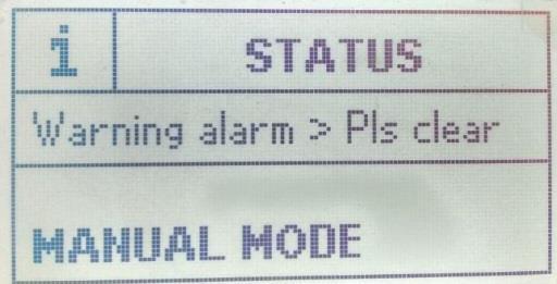
26 Mode Delay. SEDEMAC In Auto mode, if Remote start/stop is configured, then the controller will wake up after receiving Remote Start command. Press and hold any key for minimum one sec. 11 Alarms The GC500 controller allows to configure several /Electrical trip, and Notification alarms such as Low Oil Pressure, Over Load and many more. An alarm condition occurs when the preconfigured parameter is out of preset level. On initiation of an alarm, the Alarm LED will start blinking and Sounder alarm will be activated if configured. The controller will display name of alarms along with count on ALARMS screen and the nature of alarm on ENGINE STATUS screen. For acknowledging the alarms, press UP key. All the alarms will be activated at the end of Safety Monitoring Start Delay duration. The controller will not issue the start command if the alarm left unacknowledged. # Alarm Actions Description 1 Notification Controller will display message on the display screen and this will not affect the genset start stop operation. 2 alarms serves to draw operator's attention to an undesirable condition without affecting genset's operation in genset ON condition. The genset cannot be started without acknowledging the warning alarms. 3 Electrical trip In this alarm action type load is taken off from the genset, engine cooling timer begins, after which genset is stopped. 4 In this alarm action type load is taken off from the genset and the genset is immediately stopped by skipping Engine Cooling Time. Table 7: for types of alarms actions and their descriptions Sr. Alarms Causes Action options No. 1 Low Oil Pressure sensor Indicates that the oil pressure measured is below the preset threshold Low Oil Pressure switch Indicates that the oil pressure measured is below the preset threshold Electrical trip Notification 2 Low Fuel level Indicates that the amount of fuel level is below the sensor Low Fuel level switch 3 High Eng Temp sensor preset threshold Indicates that the amount of fuel level is below the preset threshold Indicates that the engine temperature is above the preset threshold Electrical trip Notification High Eng Temp switch 4 Low Water Level Switch Indicates that the engine temperature is above the preset threshold Indicates that radiator water level is below the preset threshold Electrical trip Notification Electrical trip Notification Page 26 of 31
27 Sr. Alarms Causes Action options No. 5 Over Speed Indicates that genset speed has exceeded the preset over speed threshold 6 Gross Over Indicates that genset speed has exceeded the preset Speed gross over speed threshold (This threshold is configurable percentage value of over speed threshold) 7 Under Speed The engine speed has fallen below the preset RPM SEDEMAC 8 R Phase Over Voltage 9 R Phase Under Voltage 10 Y Phase Over Voltage 11 Y Phase under Voltage 12 B Phase Over Voltage 13 B Phase Under Voltage 14 Over Frequency 15 Under Frequency Indicates that genset L1(R) Phase voltage has exceeded the preset over voltage threshold Indicates that geset L1(R) Phase voltage has fallen below preset under voltage threshold. Indicates that genset L2(Y) Phase voltage has exceeded the preset over voltage threshold Indicates that genset L2(Y) Phase voltage has fallen the preset over voltage threshold Indicates that genset L3(B) Phase voltage has exceeded the preset over voltage threshold Indicates that geset L3(B) Phase voltage has fallen below preset under voltage threshold. Indicates that genset output frequency has exceeded the preset threshold Indicates that genset output frequency has fallen below the preset threshold 16 Emergency Stop Configured as digital input has triggered longer than preset duration or when the immediate stutdown is required 17 Charge Fail The charging alternator voltage has dropped below the supply voltage 18 Battery Over Voltage 19 Battery Under Voltage 20 Maintenance Due 21 Auxiliary input / User defined name The battery voltage has exceeded the preset threshold The battery voltage has fallen below the preset threshold Indicates that engine running hours has exceeded the preset hours limit or maintenance due date has occurred and filter servicing is required. Configured auxiliary input has triggered longer than preset duration 22 Fail To Stop It is detected that genset is still running after sending stop command Notification Electrical trip Notification Electrical trip Notification Notification Electrical trip Notification Page 27 of 31
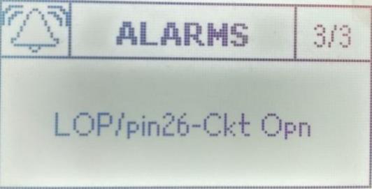
28 Sr. Alarms Causes Action options No. 23 Fail To Start Indicates that genset has not started after the preset number of Start attempts SEDEMAC 24 Fuel Theft The fuel consumption has exceeded the preset threshold 25 Eng Temp / The temperature sensor is detected as not being pin24 - Ckt present Opn 26 Fuel Level Ckt Open The fuel level sensor is detected as not being present 27 LOP / pin26 - Ckt Opn The oil pressure sensor is detected as not being present 28 DG Phase Reversed 29 High Oil Pressure sensor High Oil Pressure switch Alternator phase sequence (R-Y-B) is not correct Indicates that the oil pressure measured is above the preset threshold Indicates that the oil pressure measured is above the preset threshold Table 8: for alarms and their causes Electrical trip Electrical trip Notification 12 Troubleshooting This section explains the common faults and their remedial actions: Sr. No. Faults Possible Issues in MANUAL Mode Remedial Actions 1 The controller does not power ON. Check the battery voltage. Check the fuse on the battery supply. Check continuity between battery positive and controller terminal # 2. Check continuity between battery ground and controller terminal # 1. 2 The controller fails to crank-start the engine. Check the battery voltage. Enter into configuration mode in controller and verify the configuration for the START output. Also, check that START output is working correctly by measuring its output voltage. Enter into configuration mode in controller and verify the configuration of CRANK DISCONNECT method. Verify the configuration of LLOP SWITCH polarity. Also, ensure that the lube oil pressure switch & sensor are working OK. Check their wiring. Page 28 of 31
29 Sr. Faults No. 3 The Emergency Stop alarm comes up even when the Emergency Stop is not pressed. 4 The controller generates unnecessary Alarms or Alarms 5 The controller reports Charge Fail alarm. 6 The controller shows genset ON while genset is at rest. Fail To Stop alarm when genset is at rest. 7 The controller issues unnecessary crank-start command immediately after power on. 8 The engine runs, but the controller shows genset to be OFF. 9 Controller displays incorrect reading for any of LOP, Fuel Level, Temperature sensors. Remedial Actions Check if the Emergency Stop switch is working OK. Also check its wiring. Enter into configuration mode in controller and verify the configuration of EMERGENCY STOP polarity. Check the respective switch/sensor and wiring. Enter into configuration mode in the controller and verify the respective threshold configuration. To check if the controller's charging alternator terminal is working or not: Disconnect the charging alternator wiring from the controller's terminal # 7. Short the terminal # 7 to the ground through a DC ammeter. Crank-start the engine. The DC ammeter should indicate the current in the range ma for ~30 seconds. If yes, the controller's charging alternator terminal is working OK. Disconnect and re-connect the charging alternator to the controller's terminal # 7. Check if the charging alternator is working OK or not. Enter the configuration mode in the controller and verify the configuration for the LLOP and LOP. Check their wiring also. Ensure that the mains voltage wiring is not connected by mistake to the controller's genset voltage terminals. Ensure that the controller's output terminal is not directly connected to the starter relay. The controller's output should be given to an intermediate relay which should inturn power the starter relay. The controller can get permanently damaged and will need to be replaced if this precaution is not taken. Check start-relay connection with the suitable controller terminal. Enter into configuration mode in the controller and verify the configuration for START MODE and the START RELAY output polarity. **Check if alternator voltage signal (R phase) is received by the controller terminals. Check if the LOP and LLOP are working OK. Also check their wiring to the controller. Check respective sensor and its wiring. Enter into configuration mode in the controller and verify the calibration for Page 29 of 31
30 Sr. No. Faults Remedial Actions the respective sensor in configuration. SEDEMAC 10 Controller displays incorrect reading of Fuel Level sensor 11 The controller displays incorrect engine RPM. 12 The controller screen freezes or hangs up. 13 GCU showing wrong engine temperature / lube oil pressure Check if the ground connection of the sensor is same as that set in the configuration mode (i.e whether it is connected to battery s negative terminal or Engine body) Check wiring of the main alternator s R-phase and neutral to the controller. Reset the controller power. Check whether the GCU s pin # 41 (SCP) is connected with the engine body 14 GCU showing wrong fuel level Enter into configuration mode, check whether the Fuel analog input configuration for FUEL SENSOR REF is as per the physical connection (ie if the configuration is set as battery negative the connection of the fuel sensor -Ve has to be on battery negative. If the configuration is set as Engine body the connection of the fuel sensor negative has to be on the engine body) Page 30 of 31

31 Disclaimer: Due to continuous development, the details provided in this document are subject to change without any prior notice. SEDEMAC Mechatronics Pvt Ltd C9-10, C Block, MIDC Bhosari Pune , India For any support write us at: support@sedemac.com For any support call us: Page 31 of 31
MANUAL FOR GC2599 CONTROLLER ABSTRACT. This manual is intended as an information guide for operating SEDEMAC's GC2599 genset controller.
 ABSTRACT This manual is intended as an information guide for operating SEDEMAC's GC2599 genset controller. MANUAL FOR GC2599 CONTROLLER Doc #SED-MAN-GC2599-002 Date: 28-Sep-2017 Product Manual Revision
MANUAL FOR ROTARY ACTUATORS ABSTRACT. Doc #SED-MAN-Rotary Actuators-002. Date: 11-Sep-2017
 ABSTRACT MANUAL FOR ROTARY This manual is intended as an information guide for operating SEDEMAC's Rotary Actuator. Doc #SED-MAN-Rotary Actuators-002 Date: 11-Sep-2017 ACTUATORS Product Manual Version
OPERATING INSTRUCTIONS ECON-M
 OPERATING INSTRUCTIONS ECON-M INDEX 1.0 Introduction 2.0 Salient features, Protection & Supervision 3.0 Display/ Front Panel 4.0 Switches Description 5.0 LED Annunciations Description 6.0 Lamp Test 7.0
HGM1780. Automatic Genset Controller USER MANUAL. Smartgen Technology
 HGM1780 Automatic Genset Controller USER MANUAL Smartgen Technology Smartgen Technology Co., Ltd No. 28 Jinsuo Road Zhengzhou Henan Province P. R. China Tel: 0086-371-67988888/67981888 0086-371-67991553/67992951
MODEL 520 REMOTE START ENGINE MANAGEMENT SYSTEM
 MODEL 520 REMOTE START ENGINE MANAGEMENT SYSTEM DSE 520 ISSUE 4 4/4/02 MR 1 TABLE OF CONTENTS Section Page INTRODUCTION... 4 CLARIFICATION OF NOTATION USED WITHIN THIS PUBLICATION.... 4 1. OPERATION...
DEEP SEA ELECTRONICS PLC
 COMPLEX SOLUTIONS MADE SIMPLE DEEP SEA ELECTRONICS PLC DSE704 AUTOSTART CONTROL MODULE OPERATING MANUAL 057-042 704 Operating Instructions Issue 2.1 18/06/2007 11:27:00 JR - 1 - Deep Sea Electronics Plc
DEEP SEA ELECTRONICS PLC
 COMPLEX SOLUTIONS MADE SIMPLE. DEEP SEA ELECTRONICS PLC DSE4120 AUTO MAINS FAILURE MODULE OPERATING MANUAL Deep Sea Electronics Plc Highfield House Hunmanby North Yorkshire YO14 0PH ENGLAND Sales Tel:
Automatic Genset Controller, AGC-4 Display readings Push-button functions Alarm handling Log list
 OPERATOR'S MANUAL Automatic Genset Controller, AGC-4 Display readings Push-button functions handling Log list DEIF A/S Frisenborgvej 33 DK-7800 Skive Tel.: +45 9614 9614 Fax: +45 9614 9615 info@deif.com
ICON 2 1. FEATURES AND CHARACTEIRICS
 ICON 2 1. FEATURES AND CHARACTEIRICS High end Micro-controller(DSP) technology Wide range of auxiliary supply: 7V to 45Vdc. Low power Consumption : 200 ma @ 12 V DC. Alphanumeric 16X4 or 16X2 LCD display
702 AUTOMATIC START MODULE OPERATING INSTRUCTIONS
 702 AUTOMATIC START MODULE OPERATING INSTRUCTIONS > TABLE OF CONTENTS 1 DESCRIPTION OF OPERATION... 4 1.1 MANUAL MODE OPERATION... 4 1.2 AUTOMATIC MODE OF OPERATION...
Deep Sea Electronics Plc
 Deep Sea Electronics Plc 550 Operators Manual Author Miles Revell Deep Sea Electronics Plc Highfield House Hunmanby Industrial Estate North Yorkshire YO14 0PH ENGLAND Tel +44 (0) 1723 890099 Fax +44 (0)
Auto Mains Failure AMF Controller AE10113
 Auto Mains Failure AMF Controller AE03 Auto Mains Failure DESCRIPTION AMF Controller AE03 is an Automatic Mains Failure controller, which activates the generator during power failure & vice versa. The
HGM1750 Genset Security Module USER MANUAL Smartgen Technology
 HGM1750 Genset Security Module USER MANUAL Smartgen Technology CONTENT 1. SUMMARY... 4 2. PERFORMANCE AND CHARACTERISTICS... 5 3. SPECIFICATION... 7 4. OPERATION... 8 5. PROTECTION... 9 6. PARAMETER RANGE
DEEP SEA ELECTRONICS PLC
 COMPLEX SOLUTIONS MADE SIMPLE DEEP SEA ELECTRONICS PLC DSE720 AUTOSTART CONTROL MODULE OPERATING MANUAL http://bestgenerator.spb.ru/?page_id=6765 Deep Sea Electronics Plc Highfield House Hunmanby North
DEEP SEA ELECTRONICS PLC
 COMPLEX SOLUTIONS MADE SIMPLE. DEEP SEA ELECTRONICS PLC DSE710 AUTOSTART CONTROL MODULE OPERATING MANUAL Deep Sea Electronics Plc Highfield House Hunmanby North Yorkshire YO14 0PH ENGLAND Sales Tel: +44
5220 AUTOMATIC MAINS FAILURE MODULE OPERATING MANUAL
 5220 AUTOMATIC MAINS FAILURE MODULE OPERATING MANUAL > Section DSE Model 5220 Automatic Mains Failure & Instrumentation System Operators Manual TABLE OF CONTENTS
DEEP SEA ELECTRONICS PLC
 DEEP SEA ELECTRONICS PLC 703 AUTOMATIC START MODULE OPERATING INSTRUCTIONS Author:- John Ruddock 703 Operating Instructions Issue Beta1 25/08/2003 2:45 PM JR - 1 - >
Deep Sea Electronics Plc
 Deep Sea Electronics Plc 5120 AUTOMATIC MAINS FAILURE MODULE OPERATING MANUAL Author: Anthony Manton Deep Sea Electronics Plc Highfield House Hunmanby North Yorkshire YO14 0PH England Tel: +44 (0) 1723
OPERATING INSTRUCTIONS MCP-MT1
 OPERATING INSTRUCTIONS MCP-MT1 MRM PROCOM Pvt Ltd ISO-9001-2008 certified organization Plot No. : 20-21, Industrial Estate, Sector - 59, Phase-II, Faridabad (Haryana) Ph.: 0129-4700400(10 Lines) Email:
HGM6320T AUTOMATIC GENERATOR CONTROLLER USER MANUAL
 HGM6320T AUTOMATIC GENERATOR CONTROLLER USER MANUAL Smartgen Technology CONTENT 1 SUMMARY... 4 2 PERFORMANCE AND CHARACTERISTICS... 4 3 SPECIFICATION... 5 4 OPERATION... 6 4.1 LCD DISPLAY... 6 4.2 KEY
EG1299. Variable Speed Engine Controller for Telecom Backup Gensets SEDEMAC EG1299 HIGHLIGHTS
 EG1299 Variable Speed Engine Controller for Telecom Backup Gensets HIGHLIGHTS Built-in electronic governor module Variable and fixed speed operation Configurable 0% droop with paralleling support RS485
HSC940 Genset Controller CONTENTS 1 OVERVIEW PERFORMANCE AND CHARACTERISTICS SPECIFICATION OPERATION KEY FUNCTIONS...
 CONTENTS 1 OVERVIEW... 4 2 PERFORMANCE AND CHARACTERISTICS... 5 3 SPECIFICATION... 7 4 OPERATION... 8 4.1 KEY FUNCTIONS... 8 4.2 INDICATOR LIGHT... 9 4.3 AUTO START/STOP OPERATION... 10 4.4 MANUAL START/STOP
HGM7100N SERIES (HGM7110N/7120N) GENSET CONTROLLER USER MANUAL
 GENSET CONTROLLER USER MANUAL") HGM7100N SERIES (HGM7110N/7120N) GENSET CONTROLLER USER MANUAL SMARTGEN (ZHENGZHOU) TECHNOLOGY CO., LTD. Chinese trademark English trademark SmartGen make your generator smart SmartGen Technology Co.,
HGM7100N SERIES (HGM7110N/7120N) GENSET CONTROLLER USER MANUAL SMARTGEN (ZHENGZHOU) TECHNOLOGY CO., LTD. Chinese trademark English trademark SmartGen make your generator smart SmartGen Technology Co.,
USER MANUAL ZHENGZHOU SMARTGEN TECHNOLOGY CO.,LTD
 HGM400 Series Genset Controller (HGM410/HGM420) USER MANUAL ZHENGZHOU SMARTGEN TECHNOLOGY CO.,LTD CONTENTS 1 OVERVIEW... 5 2 PERFORMANCE AND CHARACTERISTICS... 6 3 SPECIFICATION... 8 4 OPERATION... 9 4.1
OPERATING INSTRUCTION: DGC-6D/6D1I
 OPERATING INSTRUCTION: DGC-6D/6D1I GCB Auto Man Stop Fail - PROCOM Pvt Ltd MRM PROCOM Plot No. : 20-21, Industrial Estate, Sector - 59, Phase-II, Faridabad (Haryana) Ph.: 0129-4700400(10 Lines) Email:
HGM72 Automatic Generator Module OPERATING MANUAL Smartgen Electronic
 HGM72 Automatic Generator Module OPERATING MANUAL Smartgen Electronic CONTENT 1 SUMMARY... 4 2 FEATURES... 4 3 SPECIFICATION... 4 4 DISPLAY SYMBOL AND OPERATION... 5 5 ALARM... 7 6 PARAMETERS TABLE (ONLY
HGM1780 AUTOMATIC GENERATOR MODULE CONTENT 1. SUMMARY PERFORMANCE AND CHARACTERISTICS SPECIFICATION OPERATION...
 CONTENT 1. SUMMARY...4 2. PERFORMANCE AND CHARACTERISTICS...4 3. SPECIFICATION...5 4. OPERATION...6 4.1. DISPLAY PANEL...6 4.2. LCD ICON INSTRUCTION...7 4.3. DISPLAY INSTRUCTIONS...7 4.4. DISPLAY DESCRIPTION...8
DSEULTRA DSE6000 Quick Start Guide Document Number
 n DSEULTRA DSE6000 Quick Start Guide Document Number 057-102 Author : John Ruddock Deep Sea Electronics Plc Highfield House Hunmanby North Yorkshire YO14 0PH ENGLAND Sales Tel: +44 (0) 1723 890099 Sales
HGM1770 Automatic Generator Control Module OPERATING MANUAL Smartgen Electronic
 HGM1770 Automatic Generator Control Module OPERATING MANUAL Smartgen Electronic CONTENT 1. SUMMARY... 4 2. PERFORMANCE AND CHARACTERISTICS... 4 3. SPECIFICATIONS... 5 4. OPERATION... 6 5. PROTECTION...
HGM72 Automatic Generator Module OPERATING MANUAL Smartgen Electronic
 HGM72 Automatic Generator Module OPERATING MANUAL Smartgen Electronic Smartgen Electronic Equipment Co., Ltd No.28 Jinsuo Road Zhengzhou Henan Province P.R.China Tel: 0086-371-67988888/67981888 0086-371-67991553/67992951/67992952
DKG-114 MANUAL AND REMOTE START UNIT
 DKG-114 MANUAL AND REMOTE START UNIT FEATURES Both manual and remote controlled engine starting and stopping, Automatic shutdown on fault condition, Optional cooldown cycle on remote start operation, Optional
HGM6410/6420 AUTOMATIC GENERATOR MODULE WITH J1939 INTERFACE SOFTWARE MANUAL
 HGM6410/6420 AUTOMATIC GENERATOR MODULE WITH J1939 INTERFACE SOFTWARE MANUAL SMARTGEN ELECTRONICS Smartgen Electronic Equipment Co., Ltd No.12 Dongqing Street Zhengzhou Henan Province P.R.China Tel : (0086)-371-67992951
REVISED ATM72 Auto Transfer Module
 Capricorn Controls DA01ATM1-1 Data & Application Note Page 1 of 8 REVISED - - - ATM72 Auto Transfer Module Genset Controls - Timers - Monitors - Trips - Battery Charging - Spares & Accessories - Custom
DEEP SEA ELECTRONICS PLC
 COMPLEX SOLUTIONS MADE SIMPLE. DEEP SEA ELECTRONICS PLC DSE5220 AUTO MAINS FAILURE MODULE OPERATING MANUAL Deep Sea Electronics Plc Highfield House Hunmanby North Yorkshire YO14 0PH ENGLAND Sales Tel:
Cat/DCG-6D1I/07-08/03/Ver 1 Page 2/10
 Cat/DCG-6D1I/07-08/03/Ver 1 Page 2/10 Index 1.1 Introduction 1.2 Salient Feature of the DGC-6D 1.2.1 Protection & Supervision 1.2.2 Measurement & Display 1.2.3 LED Indications 1.2.4 Timer 1.3 Function
DEEP SEA ELECTRONICS PLC
 COMPLEX SOLUTIONS MADE SIMPLE. DEEP SEA ELECTRONICS PLC DSE5110 AUTOSTART CONTROL MODULE OPERATING MANUAL Deep Sea Electronics Plc Highfield House Hunmanby North Yorkshire YO14 0PH ENGLAND Sales Tel: +44
HGM6320T AUTOMATIC GENERATOR CONTROLLER USER MANUAL
 HGM6320T AUTOMATIC GENERATOR CONTROLLER USER MANUAL Smartgen Technology Smartgen Technology Co., Ltd No. 28 Jinsuo Road Zhengzhou Henan Province P. R. China Tel: 0086-371-67988888/67981888 0086-371-67991553/67992951/67992952
GENSET CONTROL MODULE A121A / A241A
 Technical Data Sheet GENSET CONTROL MODULE A121A / A241A Features: Models for both 12V and 24V systems. One model for both spark ignition and diesel engines. 4-alarm light outputs with lamp-test provisions.
Flight Systems. Replacement for KASSEC DESCRIPTION
 DESCRIPTION The is a universal generator controller that will start, stop, and provide engine protection for most generators. Universal replacement for both the 90353 and 90354 KASSEC Compatible with most
GCU-10. Automatic Engine Control Unit Operators Manual
 GCU-10 Automatic Engine Control Unit Operators Manual KUTAI ELECTRONICS INDUSTRY CO., LTD. TEL : +886-7-8121771 FAX : +886-7-8121775 Website : www.kutai.com.tw Headquarters : No.3, Lane 201, Chien Fu St.,
DKG-317 MANUAL AND REMOTE START UNIT
 Tel: +54-11-4629-600 Fax:+54-11-4627-3500 http://www.cramelectro.com DKG-317 MANUAL AND REMOTE START UNIT FEATURES Manual starting and stopping Engine control Generator protection Built in alarms and warnings
SDM72 Start on Demand Modules
 Capricorn Controls DA04SDM72-2 Revised Design Page 1 of 6 SDM72 Start on Demand Modules Genset Controls - Timers - Monitors - Trips - Battery Charging - Spares & Accessories - Custom Products Application
ECU-02 Ver2.1 Automatic Engine Control Unit Operators Manual
 ECU-02 Ver2.1 Automatic Engine Control Unit Operators Manual Headquarters : No.3, Lane 201, Chien Fu St., Chyan Jenn Dist., Kaohsiung, TAIWAN Tel : + 886-7-8121771 Fax : + 886-7-8121775 URL : http://www.kutai.com.tw
HGM6310D/6320D AUTOMATIC GENERATOR MODULE USER MANUAL
 HGM6310D/6320D AUTOMATIC GENERATOR MODULE USER MANUAL SMARTGEN ELECTRONIC CONTENT 1 SUMMARY... 4 2 PERFORMANCE AND CHARACTERISTICS... 4 3 SPECIFICATION... 6 4 OPERATION... 7 4.1 KEY FUNCTION... 7 4.2 AUTOMATIC
HGM6410/6420. Automatic Generator Module. With J1939 Interface OPERATING MANUAL. Smartgen Electronics
 HGM6410/6420 Automatic Generator Module With J1939 Interface OPERATING MANUAL Smartgen Electronics Smartgen Electronic Equipment Co,.Ltd No.12 Dongqing Street Zhengzhou Henan Province P.R.China Tel : (0086)-371-67992951
Deep Sea Electronics Plc
 Deep Sea Electronics Plc 5520 Operators Manual Author Tony Manton Deep Sea Electronics Plc Highfield House Hunmanby Industrial Estate North Yorkshire YO14 0PH ENGLAND Tel +44 (0) 1723 890099 Fax +44 (0)
DEEP SEA ELECTRONICS DSE7110 MKII / DSE7120 MKII Configuration Suite PC Software Manual
 DEEP SEA ELECTRONICS DSE7110 MKII / DSE7120 MKII Configuration Suite PC Software Manual Document Number 057-185 Author: Fady Atallah DSE7110 MKII / DSE7120 MKII Configuration Suite PC Software Manual DSE7110
DEEP SEA ELECTRONICS PLC DSE3210 Configuration Suite Software Manual
 DEEP SEA ELECTRONICS PLC DSE3210 Configuration Suite Software Manual Document Number 057-152 Author : Paul Gibbons DSE3210 Configuration Suite Software Manual Issue 1 DSE3210 Configuration Suite Software
HGM6000K Series Automatic Generator Module OPERATING MANUAL Smartgen Electronic
 HGM6000K Series Automatic Generator Module OPERATING MANUAL Smartgen Electronic CONTENT 1 SUMMARY... 4 2 PERFORMANCE AND CHARACTERISTICS... 4 3 SPECIFICATION... 6 4 OPERATION... 6 4.1 KEY FUNCTION... 6
Advanced Genset Controller, AGC 200 Display readings Push-button functions Alarm handling Log list
 OPERATOR'S MANUAL Advanced Genset Controller, AGC 200 Display readings Push-button functions Alarm handling Log list DEIF A/S Frisenborgvej 33 DK-7800 Skive Tel.: +45 9614 9614 Fax: +45 9614 9615 info@deif.com
GENSET CONTROL MODULE
 HGM7200/HGM7100 Series AUTOMATIC GENSET CONTROL MODULE User Manual SMARTGEN TECHNOLOGY Smartgen Technology Co., Ltd No.28 Jinsuo Road Zhengzhou Henan Province P. R. China Tel: 0086-371-67988888/67981888
Cascade CD101 Auto-Start Controller. Installation and Operations Manual Sections 40 & 75
 Cascade CD101 Auto-Start Controller Installation and Operations Manual 00-02-0594 2018-02-15 Sections 40 & 75 In order to consistently bring you the highest quality, full featured products, we reserve
DEEP SEA ELECTRONICS
 DEEP SEA ELECTRONICS DSEE100 Configuration Suite PC Software Manual Document Number: 057-267 Author: Bedig Boghossian 057-267 ISSUE: 1 DSEE100 Configuration Suite PC Software Manual DEEP SEA ELECTRONICS
HGM6400 Automatic Genset Controller (With J1939 Interface) USER MANUAL Smartgen Technology
 USER MANUAL Smartgen Technology") HGM6400 Automatic Genset Controller (With J1939 Interface) USER MANUAL Smartgen Technology Chinese trademark English trademark Smartgen make your generator smart Smartgen Technology Co., Ltd No. 28 Jinsuo
HGM6400 Automatic Genset Controller (With J1939 Interface) USER MANUAL Smartgen Technology Chinese trademark English trademark Smartgen make your generator smart Smartgen Technology Co., Ltd No. 28 Jinsuo
GENSET CONTROL MODULE LEVEL 1 A121CM / A241CM. Special logic to re-establish cranking following a false start.
 Technical Data Sheet GENSET CONTROL MODULE LEVEL 1 A121CM / A241CM Features: Models for both 12V and 24V systems. One model for both spark ignition and diesel engines. 5-alarm light outputs with lamp-test
DEEP SEA ELECTRONICS
 DEEP SEA ELECTRONICS DSE6010 MKII / DSE6020 MKII Configuration Suite PC Software Manual Document Number: 057-223 Author: Fady Atallah DSE6010 MKII / DSE6020 MKII Configuration Suite PC Software Manual
HGM501 Gen-set Controller USER MANUAL. Smartgen Technology
 HGM501 Gen-set Controller USER MANUAL Smartgen Technology Contents 1. 2. 3. 4. 5. 6. 7. 8. 9. OVERVIEW... 4 PERFORMANCE AND CHARACTERISTICS... 4 TECHNICAL DATA... 5 OPERATION... 6 4.1. BUTTON DESCRIPTION...
DKG-215 MANUAL AND REMOTE START UNIT
 DKG-215 MANUAL AND REMOTE START UNIT FEATURES Manual and remote starting and stopping Zero power consumption at rest Engine control mode available Generator protection Built in alarms and warnings 1 phase
Generator Sets Controller 210. Operation Manual. Ver1.0
 Generator Sets Controller 210 Operation Manual Ver1.0 Note This information could include technical inaccuracies or typographical error. Manufacturer may make improvements and/or changes in the product(s)
TG350 User Manual. Manual Revision: Min. FW Revision: Date Released: 09/01/ DYNAGEN Technologies Inc
 TG350 User Manual Manual Revision: 1.4.0 Min. FW Revision: 1.42.01 Date Released: 09/01/2014 Table of Contents 1 Introduction 1.1 Specifications... 3 2 Installation 2.1 Terminal s... 6 2.2 Typical Wiring...
Te 803 Electronic Controller. Service, Operation & Technical Information Manual
 Te 803 Electronic Controller Service, Operation & Technical Information Manual WARNING! Technical descriptions and data given in this document are accurate, to the best of our knowledge, but can be subject
HGM6100K Series Automatic Generator Module OPERATING MANUAL Smartgen Electronics
 HGM6100K Series Automatic Generator Module OPERATING MANUAL Smartgen Electronics All rights reserved. No part of this publication may be reproduced in any material form (including photocopying or storing
AUTOSTART 705S V1.00 AUTOSTART 710S / 720S / 730S V1.04 Programming Reference and Check Sheets
 The Generator Controls Division of Frank W. Murphy AUTOSTART 705S V1.00 AUTOSTART 710S / 720S / 730S V1.04 Programming Reference and Check Sheets MODEX AUTOMATION FRANK W. MURPHY LTD. Church Road Laverstock
DKG-109 AUTOMATIC MAINS FAILURE UNIT
 Tel: +90-216-466 84 60 Fax: +90-216 364 65 65 datakom@datakom.com.tr http://www.datakom.com.tr DKG-109 AUTOMATIC MAINS FAILURE UNIT FEATURES Automatic mains failure Engine control Generator protection
HGM6000K Series Automatic Generator Module USER MANUAL Smartgen Technology
 HGM6000K Series Automatic Generator Module USER MANUAL Smartgen Technology Chinese trademark English trademark Smartgen make your generator smart Smartgen Technology Co., Ltd. No. 28 Jinsuo Road Zhengzhou
DEEP SEA ELECTRONICS PLC DSE3210 CONTROLLER OPERATORS MANUAL
 DEEP SEA ELECTRONICS PLC DSE3210 CONTROLLER OPERATORS MANUAL Document number 057-153 Author: Allan Jones DSE3210 Operators Manual Issue 1 http://bestgenerator.spb.ru/?page_id=6765 Deep Sea Electronics
GENSET CONTROL MODULE A121H / A241H. User selectable time delays for engine start and engine stop (cool down).
.") Technical Data Sheet GENSET CONTROL MODULE A121H / A241H Features: Models for both 12V and 24V systems. One model for both spark ignition and diesel engines. 4-alarm light outputs with lamp-test provisions.
Technical Data Sheet GENSET CONTROL MODULE A121H / A241H Features: Models for both 12V and 24V systems. One model for both spark ignition and diesel engines. 4-alarm light outputs with lamp-test provisions.
HGM9510 GENSET PARALLEL (WITH GENSET) UNIT USER MANUAL
 UNIT USER MANUAL") HGM9510 GENSET PARALLEL (WITH GENSET) UNIT USER MANUAL SMARTGEN (ZHENGZHOU) TECHNOLOGY CO.,LTD. Chinese trademark English trademark SmartGen make your generator smart SmartGen Technology Co., Ltd. No.
HGM9510 GENSET PARALLEL (WITH GENSET) UNIT USER MANUAL SMARTGEN (ZHENGZHOU) TECHNOLOGY CO.,LTD. Chinese trademark English trademark SmartGen make your generator smart SmartGen Technology Co., Ltd. No.
DKG-707 MULTI GENSET PARALLELLING UNIT WITH J1939 INTERFACE
 DKG-707 MULTI GENSET PARALLELLING UNIT WITH J1939 INTERFACE STANDARD FEATURES Automatic and manual start Multi genset synchronization (up to 8 gensets) Multi genset load sharing (up to 8 gensets) Both
DKG-207 AUTOMATIC MAINS FAILURE AND REMOTE START UNIT
 DKG-207 AUTOMATIC MAINS FAILURE AND REMOTE START UNIT FEATURES Automatic mains failure, Engine control, Gas engine support, Generator protection, Built in alarms and warnings, 3 phase mains voltage inputs
GENSET CONTROL MODULE LEVEL 0 A120A. User selectable time delays for engine start and engine stop (cool down).
.") Technical Data Sheet GENSET CONTROL MODULE LEVEL 0 A120A Features: One model for both spark ignition and diesel engines. 4-alarm light outputs with automatic lamp-test provision. Overspeed adjustment not
Technical Data Sheet GENSET CONTROL MODULE LEVEL 0 A120A Features: One model for both spark ignition and diesel engines. 4-alarm light outputs with automatic lamp-test provision. Overspeed adjustment not
DKG-109J AUTOMATIC MAINS FAILURE UNIT
 DKG-109J AUTOMATIC MAINS FAILURE UNIT CANBUS VERSION FEATURES True RMS measurements Automatic mains failure ECU control and monitoring through J1939 CAN J1939 ECU warnings displayed as text Various engine
TRIPS AND FAULT FINDING
 WWW.SDS.LTD.UK 0117 9381800 Trips and Fault Finding Chapter 6 6-1 TRIPS AND FAULT FINDING Trips What Happens when a Trip Occurs When a trip occurs, the drive s power stage is immediately disabled causing
DKG-509 AUTOMATIC MAINS FAILURE UNIT
 DKG-509 AUTOMATIC MAINS FAILURE UNIT CANBUS AND MPU VERSIONS DESCRIPTION The controller is a comprehensive AMF unit for single genset standby or dual genset mutual standby operations. The unit is available
The measurements module provides the following engine features information:
 1. INTRODUCTION The CEM6 control board is a monitoring network signal and monitoring and control generator feeding device. The device consists of 2 different modules: - Visualization module. The visualization
USER S MANUAL AMF TRINITY. AMF Operational Manual
 USER S MANUAL AMF This document contains the latest technical information about AMF. The unit is tested against latest "MTE" Standard Model PRS400.3 having basic accuracy of 0.02%, traceable upto International
STANDARD OWNER S MANUAL
 WILLIE 1.0 STANDARD OWNER S MANUAL OPERATION, MAINTENANCE, & TROUBLESHOOTING STANDARD INSTRUCTIONS FOR ALL SYSTEMS DSE 3100 4/28/2011 Willis Power Systems 2950 N Martin Springfield, MO 65803 417.831.2520
OPERATING MANUAL Digital Diesel Control Remote control panel for WhisperPower generator sets
 Art. nr. 40200261 OPERATING MANUAL Digital Diesel Control Remote control panel for WhisperPower generator sets WHISPERPOWER BV Kelvinlaan 82 9207 JB Drachten Netherlands Tel.: +31-512-571550 Fax.: +31-512-571599
Model H30 Operation Manual
 Model H30 Operation Manual Model H30 Version 1.0 August 1, 2007 2 135 West Davenport Street Rhinelander WI 54501 Phone: 866.441.7997 Fax: 866.278.0036 info@houstonst.com www.houstonst.com 3 Table of Contents
EPAS Desktop Pro Software User Manual
 Software User Manual Issue 1.10 Contents 1 Introduction 4 1.1 What is EPAS Desktop Pro? 4 1.2 About This Manual 4 1.3 Typographical Conventions 5 1.4 Getting Technical Support 5 2 Getting Started 6 2.1
MD10. Engine Controller. Installation and User Manual for the MD10 Engine Controller. Full Version
 MD10 Engine Controller Installation and User Manual for the MD10 Engine Controller. Full Version File: MartinMD10rev1.4.doc May 16, 2002 2 READ MANUAL BEFORE INSTALLING UNIT Receipt of shipment and warranty
EPM72 Engine Protection Module
 Capricorn Controls DA01EPM1-1 Data & Application Note Page 1 of 8 EPM2 Engine Protection Module Genset Controls - Timers - Monitors - Trips - Battery Charging - Spares & Accessories - Custom Products All
CURTIS TOLEDO. AF Series Compressors VS models with VFD WARNING
 AUGUST, 2004 REV.A CURTIS TOLEDO OPERATOR S MANUAL SUPPLEMENT AF Series Compressors VS models with VFD WARNING Personal injury and/or equipment damage will result by failing to pay attention to the vital
PSM72H Push-Button Start Module
 Capricorn Controls DA02PSM72H1-2 Data & Application Note Page 1 of 6 PSM72H Push-Button Start Module Genset Controls - Timers/Monitors/Trips - Battery Charging Spares & Accessories - Custom Products Ultra
HAT700 Series HAT700/HAT700I/HAT700B/HAT700BI/HAT700S ATS CONTROLLER USER MANUAL
 HAT700 Series HAT700/HAT700I/HAT700B/HAT700BI/HAT700S ATS CONTROLLER USER MANUAL ZHENGZHOU SMARTGEN TECHNOLOGY CO.,LTD Software Version Version Date Note 1.0 2014-09-09 Original release. 1.1 2015-03-04
HGM7110DC DC Genset Controller USER MANUAL ZHENGZHOU SMARTGEN TECHNOLOGY CO.,LTD
 HGM7110DC DC Genset Controller USER MANUAL ZHENGZHOU SMARTGEN TECHNOLOGY CO.,LTD Chinese trademark English trademark Smartgen make your generator smart Smartgen Technology Co., Ltd. No. 28 Jinsuo Road
DEEP SEA ELECTRONICS PLC DSEE100 Operator Manual
 DEEP SEA ELECTRONICS PLC DSEE100 Operator Manual Document Number: 057-273 Author: Fady Atallah 057-273 ISSUE: 2 DSEE100 Operator Manual Deep Sea Electronics Plc Highfield House Hunmanby North Yorkshire
1. AC VOLTS: Displays generator output in voltage. 2. AC FREQUENCY: Displays the speed of the generator set in Hertz.
 1. AC VOLTS: Displays generator output in voltage. 2. AC FREQUENCY: Displays the speed of the generator set in Hertz. 3. AMMETER/PERCENT OF LOAD: Displays the load on the generator in amps or in percentage.
HGM9520 Genset Parallel (With Mains) Unit USER MANUAL. Smartgen Technology
 Unit USER MANUAL. Smartgen Technology") USER MANUAL Smartgen Technology Chinese trademark English trademark Smartgen make your generator smart Smartgen Technology Co., Ltd. No. 28 Jinsuo Road Zhengzhou city Henan Province P. R. China Tel: +86-371-67988888/67981888
USER MANUAL Smartgen Technology Chinese trademark English trademark Smartgen make your generator smart Smartgen Technology Co., Ltd. No. 28 Jinsuo Road Zhengzhou city Henan Province P. R. China Tel: +86-371-67988888/67981888
PowerView PV380-R2 Mechanical Configuration
 PowerView PV380-R2 Mechanical Configuration Operations Manual *Products covered in this document comply with European Council electromagnetic compatibility directive 2004/108/EC and electrical safety directive
ANALOG CONTROL PANEL
 ANALOG CONTROL PANEL 1. AC VOLTS: Displays generator output in voltage. 2. AC FREQUENCY: Displays the speed of the generator set in Hertz. 3. Percent of Load: Displays percentage of load on the generator.
DKG-705 AUTOMATIC MAINS FAILURE AND REMOTE START UNIT WITH PARALLEL TO MAINS AND DUAL GENSET PARALLEL FEATURES
 Genset Automation Control Pte Ltd DKG-705 AUTOMATIC MAINS FAILURE AND REMOTE START UNIT WITH PARALLEL TO MAINS AND DUAL GENSET PARALLEL FEATURES FEATURES Automatic mains failure, Remote start operation,
DEEP SEA ELECTRONICS PLC DSEL401 MKII Operator Manual
 DEEP SEA ELECTRONICS PLC DSEL401 MKII Operator Manual Document Number: 057-221 Author: Ashley Senior 057-221 ISSUE: 2 DSEL401 MKII Operator Manual DEEP SEA ELECTRONICS PLC Highfield House Hunmanby North
REVISION HISTORY REVISION HISTORY
 FILTER CONTROLLER REVISION HISTORY Filter Flush Controller forms part of the Netafim range of filtration controllers all designed to make filteration more reliable and economical.. Contact any of the Netafim
DEEP SEA ELECTRONICS PLC DSE7110 MKII & DSE7120 MKII Operator Manual
 DEEP SEA ELECTRONICS PLC DSE7110 MKII & DSE7120 MKII Operator Manual Document Number: 057-182 Author: Ashley Senior DSE7110 MKII & DSE7120 MKII Operator Manual ISSUE 2 DSE7110 MKII & DSE7120 MKII Operator
Designer s Reference Handbook. Automatic Gen-set Controller/GS Multi-line K SW version 2.40.X. Display unit and menu structure
 Automatic Gen-set Controller/GS Multi-line 2 4189340358K SW version 2.40.X Functional descriptions Display unit and menu structure PI-controller DEIF A/S Procedure for parameter setup Parameter list DEIF
-2- Designed to automatically operate a diesel fire pump engine when the contacts of a remote water pressure switch close.
 -1-1 -2- FUNCTION Designed to automatically operate a diesel fire pump engine when the contacts of a remote water pressure switch close. POWER SUPPLY: 240V A.C single phase supply and 12 or 24 V D.C. INDICATORS:
Installation and Maintenance Instructions. World Leader in Modular Torque Limiters. PTM-4 Load Monitor
 World Leader in Modular Torque Limiters Installation and Maintenance Instructions PTM-4 Load Monitor 1304 Twin Oaks Street Wichita Falls, Texas 76302 (940) 723-7800 Fax: (940) 723-7888 E-mail: sales@brunelcorp.com
Be2K-Plus AMF panel control wiring --
 Be2K-Plus OEM's Manual V200 - August - 014 page 1 Be2K-Plus AMF panel control wiring -- Consult Section 17.0 for software upgrades & revisions The information in this document may be subject to change
Manual and Remote Start Unit with Key Switch, 72x72 DIN Size
 Manual and Remote Start Unit with Key Switch, x DI Size FAILED TO ~~~ ~ ~ STOP 0 I Hz./ EAOM - 36 SPEED FAILURE CHARGIG FAIL Features Designed For Generator, Pump & Fire Pump Applications Remote start