STANDARD OWNER S MANUAL
|
|
|
- Abel Higgins
- 5 years ago
- Views:
Transcription

1 WILLIE 1.0 STANDARD OWNER S MANUAL OPERATION, MAINTENANCE, & TROUBLESHOOTING STANDARD INSTRUCTIONS FOR ALL SYSTEMS DSE /28/2011 Willis Power Systems 2950 N Martin Springfield, MO service@willisapu.com
2 Page 2 of 36
3 Table of Contents Willie 1.0 Standard Owner s Manual... 1 Controller Quick Start Guide... 5 Starting Your APU... 5 Set Your Temperature... 5 Introduction to the Willie Parts and Service... 6 Guidelines... 6 Maintenance Requirements... 7 Controller Quick Start Guide... 8 Starting Your APU... 8 Thermostat Quick Start... 8 DSE3000 Operating Guide... 9 Dimensions and Mounting... 9 DC Supply, Fuel, and Start Outputs Operational Instructions DSE 3100 Quickstart Starting the Engine Stopping the Engine Controls ENGINE RUNNING STOPPING SEQUENCE MANUAL OPERATION WAITING IN MANUAL MODE STARTING SEQUENCE ENGINE RUNNING Protections Warnings Shutdowns Module Display RUNNING ICON USB ICON MEMORY CORRUPTION BACKLIGHT DSE 3100 Troubleshoot Fault Finding APU Troubleshooting Guide Failure to Start Page 3 of 36
4 Engine Will Not Go to High RPM APU Engine Stops Suddenly APU Engine Overheats Oil Leaks Serpentine Drive Belt Failure (For Premium Unit Only) Alternator Failure Pneumatic Compressor Failure (For Premium Unit Only) Engine Speed Sensor Failure Air Condition Compressor Failure TRUCK INTERFACE PROBLEMS Fan Drive System Air Governor Air Intake System to APU Exhaust System Thermostat Operating Guide Fan Operating Mode Displaying the Temperature Setting the Temperature Backlight Thermostat Control Mode Manual/Permanent Hold Mode Programmable Mode Temporary Bypass Battery Replacement Indicator Configuration Menu Programming Setting the Time & Day Setting the Date Energy Saving Schedule Modifying Your Schedule Page 4 of 36
5 CONTROLLER QUICK START GUIDE Warning: Always check your thermostat batteries. Dead batteries will prevent your AC from working. STARTING YOUR APU Caution: Some trucks currently operate with the coolant temperature at 230⁰F. This temperature can cause an excessive heat load on your APU at startup, signaling your APU to shutdown. In order to run your APU properly, leave your truck engine fan running for 30 minutes while the APU is running to reduce the heat. 1. While the truck is running, press the stop button on your DSE to initiate the manual mode. 2. Press the Start button to crank the APU engine. 3. After engine starts running, do not shut down your truck and allow the truck engine fan to run for 30 minutes with the APU to reduce excessive heat load. 4. To shutdown the APU, press the Stop/Reset button. SET YOUR TEMPERATURE 1. Use the selector switch to set the fan to AUTO or ON. 2. Press one of the arrow buttons until the temperature you want is displayed. Page 5 of 36
6 INTRODUCTION TO THE WILLIE 1.0 The Willie APU offers up to 50% more engine power than competitive products and its compact and lightweight design allows for easy installation. Willie provides the power and quality while priced competitively to meet the needs of the average driver and trucking company. Willie gives built-in redundancy to a big rig s critical systems. It is designed to be serviceable and is backed by parts availability. The company provides products that achieve maximum APU-related savings in fuel and maintenance designed to offset the costs of installing emissions control equipment mandated by state idling and federal emissions laws. PARTS AND SERVICE All parts for the Willis APU are available from the factory and authorized installation centers. Warranty repairs and service must be performed by authorized service centers unless prior authorization has been obtained. Willis Power Systems Have your contact information and engine serial number ready when calling. Please leave a message with the information if the line is busy. GUIDELINES Before operating the Willis APU, be sure and read all manuals included with your purchase to understand the features of the unit. Do not remove or replace the APU s cover while the engine running. If the unit is running with the cover off, stay clear of the accessory drive belt. The APU contains hot oil and coolant under pressure. Inspect hoses and connections frequently when the engine is NOT running for signs of leakage or damage. Do not insert anything in the holes in the transmission case while the APU is running. Do not leave any foreign object in the transmission case. Do not work on any Willis APU components located on or near the truck engine when the truck engine is running. Only qualified maintenance personnel should operate the Willis APU. Page 6 of 36
7 MAINTENANCE REQUIREMENTS The Willis APU requires a minimum of maintenance, but it is important to perform maintenance actions specified here on schedule. APU run time may be checked by reading the Electronic controller s hour recorder. Refer to the DSE operation or troubleshooting section for more information. WARNING: If your APU has not been running, do not immediately shut down your truck. Allow the truck engine fan to run for 15 minutes in order to reduce the excessive heat going into your APU. Always check that the APU control is set to off before removing the cover and working on the unit. It is recommended that you take your unit to one of our service locations for routine maintenance checks. Every 50 Hours of APU Runtime Check the APU engine oil level on dipstick Every 500 Hours of Runtime Check and/or change thermostat batteries Replace the APU s engine oil and filter Replace the APU engine fuel filter Disconnect/clean ALL grounds and power connections & reseal with Plasti-coat or equivalent. Check the engine air filter Check belts and hoses for wear Check wires, harnesses, clamps, & tie wraps for wear Every 2000 Hours of APU Runtime Engine Oil Check the fuel hoses on the APU Check the five water hoses on the APU Replace the APU engine s water pump belt Use SAE 15W-40 engine oil for all temperatures. Oil should meet API classification CC/CD/CE and be replaced every 500 hours of APU runtime or when truck s oil is changed, whichever comes first. Engine Coolant No separate maintenance is needed. The APU uses the truck s coolant. Nominally, this is low-silicate 40% permanent anti-freeze by volume for temperatures down to -12⁰F and 50% by volume below -12⁰F. Page 7 of 36
8 CONTROLLER QUICK START GUIDE You have two main controllers: DSE & Thermostat. STARTING YOUR APU Caution: Some trucks currently operate with the coolant temperature at 230⁰F. This temperature can cause an excessive heat load on your APU at startup, signaling your APU to shutdown. In order to run your APU properly, leave your truck engine fan running for 30 minutes while the APU is running to reduce the heat. 1. While the truck is running, press the stop button on your DSE to initiate the manual mode. 2. Press the Start button to crank the APU engine. 3. After engine starts running, do not shut down your truck and allow the truck engine fan to run for 30 minutes with the APU to reduce excessive heat load. 4. To shutdown the APU, press the Stop/Reset button. THERMOSTAT QUICK START 1. Use the selector switch to set the fan to AUTO or ON. 2. Press one of the arrow buttons until the temperature you want is displayed. Page 8 of 36
 DC SUPPLY, FUEL, AND START OUTPUTS PIN Description CABLE NOTES No SIZE 1 DC Plant Supply Input (Negative) 2.5mm² AWG 13 2 DC Plant Supply Input (Positive) 2.")
9 DSE3000 OPERATING GUIDE Dimensions and Mounting Dimension 99mm x 79 mm x 40mm (3.9 x 3.1 x 1.6 ) Panel Cut-out 80mm x 68mm (3.2 x 2.7 ) Weight 89g (0.089kg) DC SUPPLY, FUEL, AND START OUTPUTS PIN Description CABLE NOTES No SIZE 1 DC Plant Supply Input (Negative) 2.5mm² AWG 13 2 DC Plant Supply Input (Positive) 2.5 mm² AWG 13 (Recommended Maximum Fuse 15A anti-surge) Supplies the module (2A anti-surge requirement) and all output relays 3 Output A (FUEL) 4 Output B (START) 5 Output C 6 Output D 7 Charge fail / excite 1.0mm² AWG mm² AWG mm² AWG mm² AWG mm² AWG 13 Page 9 of 36 Plant Supply Positive from terminal 2. 3 Amp rated. Plant Supply Positive from terminal 2. 3 Amp rated. Plant Supply Positive from terminal 2. 3 Amp rated. Plant Supply Positive from terminal 2. 3 Amp rated. Do not connect to ground (battery negative). If charge alternator is not fitted, leave this terminal disconnected.

10 3100 OPERATIONAL INSTRUCTIONS The following section details the function and meaning of the various controls on the module and the module s operations. Page 10 of 36


11 DSE 3100 QUICKSTART This section provides a quick start guide to the module s operation. Starting the Engine Stopping the Engine Page 11 of 36
).")

12 3100 CONTROLS Stop / Reset This button places the module into its Stop/Reset mode. This will clear any alarm conditions for which the triggering criteria have been removed. If the engine is running and the module is in Stop mode, the module will automatically instruct the changeover device to unload the generator ( Close Generator becomes inactive (if used)). The fuel supply de-energizes and the engine comes to a stand-still. Should a remote start signal be present while operating in this mode, a remote start will not occur. Auto This button places the module into its Automatic mode. This mode allows the module to control the function of the generator automatically. The module will monitor the remote start input and once a start request is made, the set will be automatically started and placed on load. Upon removal of the starting signal, the module will automatically transfer the load from the generator and shut the set down observing the stop delay timer and cooling timer as necessary. The module will then await the next start event. For further details, please see the more detailed description of Auto operation elsewhere in this manual. Start Pressing this button in auto mode will start the engine and run off load. Pressing this button in STOP/RESET mode will turn on the CAN engine ECU (when correctly configured and fitted to a compatible engine ECU). Page Pressing this button scrolls the display to show the various instruments. Page 12 of 36
13 ENGINE RUNNING Once the engine is running and all starting timers have expired, the animated icon is displayed. DSE3110 -The generator will be placed on load if configured to do so. NOTE:-THE LOAD TRANSFER SIGNAL REMAINS INACTIVE UNTIL THE OIL PRESSURE HAS RISEN. THIS PREVENTS EXCESSIVE WEAR ON THE ENGINE. If all start requests are removed, the stopping sequence will begin. STOPPING SEQUENCE The return delay timer operates to ensure that the starting request has been permanently removed and isn t just a short term removal. Should another start request be made during the cooling down period, the set will return on load. If there are no starting requests at the end of the return delay timer, the load is removed from the generator to the mains supply and the cooling timer is initiated. The cooling timer allows the set to run off load and cool sufficiently before being stopped. This is particularly important where turbo chargers are fitted to the engine. After the cooling timer has expired, the set is stopped. MANUAL OPERATION NOTE: IF A DIGITAL INPUT CONFIGURED TO PANEL LOCK IS ACTIVE, CHANGING MODULE MODES WILL NOT BE POSSIBLE. VIEWING THE INSTRUMENTS AND EVENT LOGS IS NOT AFFECTED BY PANEL LOCK. Manual mode allows the operator to start and stop the set manually, and if required change the state of the load switching devices. Module mode is active when the button is pressed. WAITING IN MANUAL MODE 1. To begin the starting sequence, press the button. 2. If protected start is disabled, the start sequence begins immediately. 3. If Protected Start is enabled, the icon is displayed to indicate manual mode and the manual LED flashes. 4. The button must be pressed once more to begin the start sequence. Page 13 of 36
14 STARTING SEQUENCE NOTE:-THERE IS NO START DELAY IN THIS MODE OF OPERATION. The fuel relay is energized and the engine is cranked. NOTE:-IF THE UNIT HAS BEEN CONFIGURED FOR CAN, COMPATIBLE ECU S WILL RECEIVE THE START COMMAND VIA CAN. If the engine fails to fire during this cranking attempt then the starter motor is disengaged for the crank rest duration after which the next start attempt is made. Should this sequence continue beyond the set number of attempts, the start sequence will be terminated and the display shows Fail to Start. The starter motor is disengaged when the engine fires. Speed detection is factory configured to be derived from the main alternator output frequency but can additionally be measured from a Magnetic Pickup mounted on the flywheel (Selected by PC using the 3000 series configuration software). Additionally, rising oil pressure can be used disconnect the starter motor (but cannot detect under-speed or over-speed). NOTE: IF THE UNIT HAS BEEN CONFIGURED FOR CAN, SPEED SENSING IS VIA CAN. After the starter motor has disengaged, the Safety On timer activates, allowing Oil Pressure, High Engine Temperature, Under-speed, Charge Fail and any delayed Auxiliary fault inputs to stabilize without triggering the fault. ENGINE RUNNING In manual mode, the load is not transferred to the generator unless a loading request is made. A loading request can come from a number of sources. Activation of an auxiliary input that has been configured to remote start on load. Activation of the inbuilt exercise scheduler if configured for on load runs. NOTE: THE LOAD TRANSFER SIGNAL REMAINS INACTIVE UNTIL THE OIL PRESSURE HAS RISEN. THIS PREVENTS EXCESSIVE WEAR ON THE ENGINE. Once the load has been transferred to the generator, it will not be automatically removed. To manually transfer the load back to the mains either: Page 14 of 36
15 1. Press the auto mode button to return to automatic mode. The set will observe all auto mode start requests and stopping timers before beginning the Auto mode stopping sequence. 2. Press the stop button De-activation of an auxiliary input that has been configured to remote start on load. STOPPING SEQUENCE In manual mode the set will continue to run until either: a) The stop button is pressed The set will immediately stop b) The auto button is pressed. The set will observe all auto mode start requests and stopping timers before beginning the Auto mode stopping sequence. PROTECTIONS When an alarm is present, the common alarm LED if configured will illuminate. The LCD display will show an icon to indicate the failure. WARNINGS Warnings are non-critical alarm conditions and do not affect the operation of the generator system, they serve to draw the operators attention to an undesirable condition. Warning alarms are self-resetting when the fault condition is removed. The icon will appear steady in the display. SHUTDOWNS 1. Shutdowns are critical alarm conditions that stop the engine and draw the operator s attention to an undesirable condition. 2. When shutdown alarms are latching, the fault must be removed and the button pressed to reset the module. The icon will appear flashing in the display. Page 15 of 36
16 8 MODULE DISPLAY TIMER ICON When the module is controlling the engine (starting and stopping) an animated timer icon will be displayed in the icon area to indicate that a timer is active, for example cranking time, crank rest etc. STOPPED ICON When there are no alarms present, an icon will be displayed to indicate the engine is stopped and what mode the unit is in. Stop Auto Manual The hand is only displayed when the arming options is enabled; otherwise the engine starts when entering the manual mode. RUNNING ICON When there are no alarms present, an animated icon is displayed to indicate the engine is running. USB ICON When a USB connection is made to the module the USB icon is displayed. MEMORY CORRUPTION If either the configuration file or engine file becomes corrupted the unit will display the icon. BACKLIGHT The backlight will be on if the unit has sufficient voltage on the power connection while the unit is turned on, unless the unit is cranking for which the backlight will be turned off. Page 16 of 36
17 DSE 3100 TROUBLESHOOT ICON DESCRIPTION AUXILIARY INPUTS FAIL START TO Auxiliary inputs can be user configured and will display the message as written by the user. The engine has not fired after the preset number of start attempts FAIL TO STOP LOW OIL PRESSURE ENGINE HIGH TEMPERATUR E UNDERSPEED OVERSPEED CHARGE FAILURE The module has detected a condition that indicates that the engine is running when it has been instructed to stop. NOTE: Fail to Stop could indicate a faulty oil pressure sensor -If engine is at rest check oil sensor wiring and configuration. The module detects that the engine oil pressure has fallen below the low oil pressure pre-alarm setting level after the Safety On timer has expired. The module detects that the engine coolant temperature has exceeded the high engine temperature pre-alarm setting level after the Safety On timer has expired. The engine speed has fallen below the under speed pre alarm setting The engine speed has risen above the over speed pre alarm setting The auxiliary charge alternator voltage is low as measured from the W/L terminal. LOW LEVEL FUEL The level detected by the fuel level sensor is below the low fuel level setting. BATTERY UNDER/ OVER VOLTAGE GENERATOR UNDER VOLTAGE The DC supply has fallen below or risen above the low/high volts setting level. The generator output voltage has fallen below the pre-set pre-alarm setting after the Safety On timer has expired. Page 17 of 36
18 GENERATOR OVER VOLTAGE GENERATOR UNDER FREQUENCY GENERATOR OVER FREQUENCY CAN ECU WARNING CAN ECU SHUTDOWN The generator output voltage has risen above the pre-set pre-alarm setting. The generator output frequency has fallen below the pre-set pre-alarm setting after the Safety On timer has expired. The generator output frequency has risen above the pre-set pre-alarm setting. The engine ECU has detected an alarm CHECK ENGINE LIGHT Contact Engine Manufacturer for support. CAN FAIL DATA The module is configured for CAN operation and does not detect data on the engine Can data link. EMERGENCY STOP MAGNETIC PICKUP FAILURE INTERNAL MEMORY ERROR The emergency stop button has been depressed. This is a fail-safe (normally closed to battery positive) input, and will immediately stop the set should the signal be removed. Removal of the battery positive supply from the emergency stop input will also remove DC supply from the Fuel and Start outputs of the controller. NOTE: The Emergency Stop Positive signal must be present otherwise the unit will shutdown. Pulses are no longer being detected from the magnetic pickup probe (3110-xxx-01 magnetic pickup version only) Either the configuration file or engine file memory is corrupted. Contact your supplier for assistance. Page 18 of 36
19 3100 FAULT FINDING SYMPTOM Unit is inoperative Read/Write configuration does not operate Unit shuts down Unit locks out on Emergency Stop Intermittent Magnetic Pick-up sensor fault Low oil Pressure fault operates after engine has fired High engine temperature fault operates after engine has fired. POSSIBLE REMEDY Check the battery and wiring to the unit. Check the DC supply. Check the DC fuse. Check DC supply voltage is not above 35 Volts or below 9 Volts Check the operating temperature is not above 70 C. Check the DC fuse. If no Emergency Stop Switch is fitted, ensure that a DC positive signal is connected to the Emergency Stop input. Check emergency stop switch is functioning correctly. Check Wiring is not open circuit. Ensure that Magnetic pick-up screen only connects to earth at one end, if connected at both ends, this enables the screen to act as an aerial and will pick up random voltages. Check pickup is correct distance from the flywheel teeth. Check engine oil pressure. Check oil pressure switch/sensor and wiring. Check configured polarity (if applicable) is correct (i.e. Normally Open or Normally Closed) or that sensor is compatible with the 3310 Module and is correctly configured. Check engine temperature. Check switch/sensor and wiring. Check configured polarity (if applicable) is correct (i.e. Normally Open or Normally Closed) or that sensor is compatible with the 3000 series module. Shutdown operates fault Check relevant switch and wiring of fault indicated on LCD display. Check configuration of input. Page 19 of 36
20 Warning operates fault Check relevant switch and wiring of fault indicated on LCD display. Check configuration of input. Fail to Start is activated after preset number of attempts to start Continuous starting of generator when in AUTO Generator fails to start on receipt of Remote Start signal. Pre-heat inoperative Check wiring of fuel solenoid. Check fuel. Check battery supply. Check battery supply is present on the Fuel output of the module. Check the speed-sensing signal is present on the 3000 series module inputs. Refer to engine manual. Check that there is no signal present on the Remote Start input. Check configured polarity is correct. Check Start Delay timer has timed out. Check signal is on Remote Start input. Confirm correct configuration of input is configured to be used as Remote Start. Check that the oil pressure switch or sensor is indicating low oil pressure to the controller. Depending upon configuration, the set will not start if oil pressure is not low. Check wiring to engine heater plugs. Check battery supply. Check battery supply is present on the Pre-heat output of module. Check preheat configuration is correct. Starter inoperative motor Check wiring to starter solenoid. Check battery supply. Check battery supply is present on the Starter output of module. Ensure that the Emergency Stop input is at Positive. Ensure oil pressure switch or sensor is indicating the low oil pressure state to the 3000 series controller. Engine runs but generator will not take load Check Warm up timer has timed out. Ensure generator load inhibit signal is not present on the module inputs. Check connections to the switching device. Note that the set will not take load in manual mode unless there is an active remote start on load signal. Page 20 of 36
21 Incorrect reading on Engine gauges Fail to stop alarm when engine is at rest Module appears to revert to an earlier configuration Set will not take load Inaccurate generator measurements on controller display Check engine is operating correctly. Check sensor and wiring. When editing a configuration using the PC software it is vital that the configuration is first read from the controller before editing it. This edited configuration must then be written back to the controller for the changes to take effect. When editing a configuration using the Front Panel Editor, be sure to press the Save button to save the change before moving to another item or exiting the Front Panel Editor. Ensure the generator is available. Check that the output configuration is correct to drive the load switch device and that all connections are correct. Remember that the set will not take load in manual mode unless a remote start on load input is present. The 3000 series controller is true RMS measuring so gives more accurate display when compared with an average meter such as an analogue panel meter or some lower specified digital multimeters. Accuracy of the controller is better than 1% of full scale. IE Gen volts full scale is 333V ph-n so accuracy is ±3.33V (1% of 333V). NOTE: THE ABOVE FAULT FINDING IS PROVIDED AS A GUIDE CHECK-LIST ONLY. AS THE MODULE CAN BE CONFIGURED TO PROVIDE A WIDE RANGE OF DIFFERENT FEATURES, ALWAYS REFER TO THE SOURCE OF YOUR MODULE CONFIGURATION IF IN DOUBT. Page 21 of 36
22 APU TROUBLESHOOTING GUIDE FAILURE TO START If there is no response at all to setting the Electronic Controller to Manual operating position, there may a problem with the Electronic Controller, the connection between the Controller and the ECM is open, the truck battery is dead, or if equipped, the battery SWITCH may be OFF. The APU engine may fail to start if: a) It lacks fuel; a fuel shortage may be due to air in the fuel line or a blocked fuel filter. b) There is a problem with the electronic controller, c) The battery or starter has a problem, d) It lacks intake air; too little intake air may be from a restriction in the air supply system. e) The starter control relay is bad, f) There is blockage in the exhaust system g) The engine speed sensor is defective. ENGINE WILL NOT GO TO HIGH RPM Engine output may be low if a) the throttle-advance solenoid is not working, b) the throttle linkage has a problem, or c) the Electronic Controller isn t sending proper output. APU ENGINE STOPS SUDDENLY Sudden stopping may be due to a) the Electronic Controller senses overheating or low oil pressure (warning light comes on), b) fuel pump failure, c) shutdown solenoid relay failure, d) fuel shutoff solenoid failure, e) engine speed sensor failure, or f) the truck s fuel tank is empty. APU ENGINE OVERHEATS If the engine overheats it will shut down (warning light will come on). Look for a coolant hose leak or blockage, or water pump or water pump belt failure. Check coolant level in the main engine. Check to make sure the coolant control valve at the truck radiator is open. Page 22 of 36
23 OIL LEAKS Oil accumulating in the bottom of the enclosure case is not normal. Check hoses from the oil pump to truck engine. Make sure the breather hose (if so equipped) extends through bottom of case. SERPENTINE DRIVE BELT FAILURE (FOR PREMIUM UNIT ONLY) Failure of the APU s internal drive belt causes all accessories, except the oil pump, to stop functioning. There will be no alternator function, no A/C compressor, and no pneumatic compressor. Failure symptom: the unit will not go to low idle and there will be a slight increase in APU engine RPM over the normal high idle RPM. ALTERNATOR FAILURE The battery will discharge when the APU is running. The APU may experience an overly high temperature reading in the enclosure as the alternator approaches failure. PNEUMATIC COMPRESSOR FAILURE (FOR PREMIUM UNIT ONLY) The truck s air tank won t pressurize when running the APU. ENGINE SPEED SENSOR FAILURE If the speed sensor fails the APU will start about 5 seconds, and attempt to run the self test. Without a speed signal the test will fail and the APU will shutdown. No fault will be recorded on the dash control. AIR CONDITION COMPRESSOR FAILURE If there is no air conditioning when running the APU it may be due to A/C compressor failure Refrigerant leak Failure of the A/C pressure switch Failures of the fan drive system on the truck. If the fan drive motor on the truck isn t working the APU s Air Conditioner compressor will cycle on and off every few seconds. Do not operate the air conditioner if this is happening. Page 23 of 36
24 TRUCK INTERFACE PROBLEMS Fan Drive System Failure of the fan drive system may be due to DC drive motor failure, clutch failure, belt failure, timer failure, or failure of the fan solenoid. As noted above, the APU s air conditioner compressor will cycle in short intervals if the fan is not being driven. Do not operate the air conditioner if this is happening. Air Governor Air pressure will either be too high or too low. Air Intake System to APU The APU won t run if the air intake hose becomes blocked. Exhaust System The APU won t start if too much restriction of the exhaust system occurs. Symptom APU does not start Check #1 Display does not have power Additional Checks Check fuses and mega fuse block Verify correct voltage at (+) post on APU Probable Cause Fuse / Relay link broken Bad battery or loose connection Actions Replace fuse and relay if necessary. Look for loose connections or corrosion in wire 12 volts minimum required Are connections clean Road dirt / tar Clean connections Display has power Check supply power at ECU This is pin(2) at the 12 pin male connector If voltage checks OK Check F1 fuse and R1 relay (Power at Starter) Bad ECU Before installing new ECU Fuse / Relay link broken System voltage Replace ECU Verify new ECU has new battery Replace fuse and relay if necessary. Look for loose connections or Page 24 of 36
25 corrosion in wire If OK, check voltage at starter wire when activated If voltage is not system voltage then Potential Bad Starter Potential Bad ECU Break in wiring harness or connection If voltage is system voltage then replace Starter Check output voltage at ECU Pin #4 at the 12 pin male connector If no voltage replace ECU Find and or replace wiring harness APU cranks but will not start Starter Glow Plugs Shut down Solenoid Check Fuse F- 1, Relay R1 Check Fuse F- 7, Relay R4 Check Fuses F- 3, F-5, Relay R2, R3 If OK then put in start mode and check voltage at glow plugs Verify shut down solenoid is working Check oil pressure switch Check temp sender Check resistance Bad Switch Bad Temp Sender Bad RPM sensor Replace fuse and relay if necessary. Look for loose connections or corrosion in wire Replace fuse and relay if necessary. Look for loose connections or corrosion in wire Replace fuse and relay if necessary. Look for loose connections or corrosion in wire If not system voltage; then broken wire. Find and replace Visual inspection Replace Oil pressure switch Replace Temp Sender With no power 135 ohms resistance Page 25 of 36
26 Exhaust Lacks Fuel Lacks Air Check resistance and proper set of speed sensor Check for blockage Check for fuel supply Check fuel filter supply Check air filter Dirt / Oil causing incorrect RPM reading Air blockage in line from fuel pump Bad or blocked filter Blockage in air delivery Remove RPM sensor and clean. Install to finger tight against the flywheel teeth and back off 1/4 turn. Tighten secure nut. Visual Pull pump supply line and observe fuel flow Replace fuel filter Repair and or replace Low engine power or bogs down Check air filter for improper cleaning and replacement Check fuel supply Check fuel filter Replace air filter Find blockage and remove Replace fuel filter Engine starts but will not run to operating RPM Throttle Solenoid Review controller icon list for fault indication Check fuse F-9 and relay R-5 Check power at throttle solenoid and test solenoid with VOM Check throttle solenoid travel by resistance ohms check Replace fuse and relay if necessary. Look for loose connections or corrosion in wire System voltage Open should be low ohms 2 or less Closed will be ohms Page 26 of 36
27 APU starts but major components are inoperable Check drive belts visually Replace AC inoperable Check in-line fuses Check belt on AC compressor Check power at AC clutch connection Check R134 level Check for evidence of R134 leakage at all AC fittings this is the most common cause of AC failure Replace fuse and relay if necessary. Look for loose connections or corrosion in wire Replace System voltage Add additional if necessary Yellowish color at fitting crimp or threads APU will not go to high idle Throttle Solenoid WPS "Willie" APU Check fuse F- 9 and relay R- 5 In Cab A/C switch connect ion Check power at throttle solenoid and test solenoid with VOM Check throttle solenoid travel by resistance ohms check Replace fuse and relay if necessary. Look for loose connections or corrosion in wire System voltage Open should be low ohms 2 or less Closed will be ohms Fix connection or replace switch Page 27 of 36
28 APU alternator not charging APU A/C compress or not working APU A/C on not cooling A/C charge A/C fan inopera ble A/C high pressur e switch Oil pressur e switch Solenoi d Check drive belt Check alternator output to system voltage 14 volts+ Check drive belt Check for system voltage at clutch wire Check for freon leakage Check for leaks Check in-line fuse / breaker and relay Check for power going through if over 300psi Check for power going through if truck engine off Check that solenoid is switching Broken belt Bad Alternator Broken belt A/C clutch Road vibration causing leak at fitting or hoses Road vibration causing leak at fitting or hoses Loose connection s Replace alternator belt Replace alternator Replace belt Replace A/C compressor and clutch Replace fittings / hoses and pull vacuum to verify proper seal. Replace fittings / hoses and pull vacuum to verify proper seal. Replace fuse and relay if necessary. Look for loose connections or corrosion in wire Replace if no system voltage Replace if no system voltage Replace if not switching Page 28 of 36
29 Bunk Controller Unit shuts down Intermittent Magnetic Pick-up sensor fault Low oil Pressure fault operates after engine has fired High engine temperature fault operates after engine has fired. Fail to Start is activated after preset number of attempts to start Pre-heat inoperative Starter motor inoperative Check DC supply voltage is not above 35 Volts or below 9 Volts Check the operating temperature is not above 160 F. Check the DC fuse. Ensure that Magnetic pick-up screen only connects to earth at one end, if connected at both ends, this enables the screen to act as an aerial and will pick up random voltages. Check pickup is correct distance from the flywheel teeth. Check engine oil pressure. Check oil pressure switch/sensor and wiring. Check configured polarity (if applicable) is correct (i.e. Normally Open or Normally Closed) Check engine temperature. Check switch/sensor and wiring. Check configured polarity (if applicable) is correct (i.e. Normally Open or Normally Closed) Check wiring of fuel solenoid. Check fuel. Check battery supply. Check battery supply is present on the Fuel output of the module. Check wiring to engine heater plugs. Check battery supply. Check battery supply is present on the Pre-heat output of module. Check pre-heat configuration is correct. Check wiring to starter solenoid. Check battery supply. Check battery supply is present on the Starter output of module. Replace fuse and relay if necessary. Look for loose connections or corrosion in wire Reset speed sensor to proper depth Replace oil sensor switch Replace temp sensor System voltage: Replace wire to component or component System voltage: Replace wire to component or component System voltage: Replace wire to component or component Page 29 of 36

30 THERMOSTAT OPERATING GUIDE The following information reflects the standard instructions for operating common thermostat settings. Making adjustments to the settings of your controller is not recommended without reviewing the provided information, and verifying with your Willis representative that the changes will not affect the performance of your unit. For detailed information, view the instruction guide that accompanies your thermostat. NOTE: YOU MUST HAVE A CLOSED LOOP (CIRCUIT) PROGRAM TO EFFECTIVELY USE THE THERMOSTAT CONTROLS. IF YOU HAVE A CLOSED LOOP AC SYSTEM ONLY, THE HEATING SYSTEM IS NOT AFFECTED BY THE THERMOSTAT. IF YOU HAVE A CLOSED LOOP HEAT AND AC SYSTEM THEN BOTH HEAT AND AC CONTROLS ARE AFFECTED BY THE THERMOSTAT. FAN OPERATING MODE Page 30 of 36

31 DISPLAYING THE TEMPERATURE Setting the Temperature BACKLIGHT THERMOSTAT CONTROL MODE Manual/Permanent Hold Mode Programmable Mode Temporary Bypass Page 31 of 36
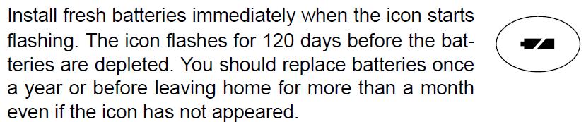
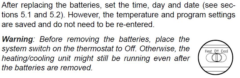
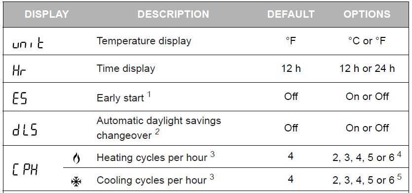
32 BATTERY REPLACEMENT INDICATOR CONFIGURATION MENU Page 32 of 36
33 PROGRAMMING Setting the Time & Day Setting the Date Page 33 of 36

34 ENERGY SAVING SCHEDULE Modifying Your Schedule Page 34 of 36

35 Page 35 of 36
36 Page 36 of 36
DSEULTRA DSE6000 Quick Start Guide Document Number
 n DSEULTRA DSE6000 Quick Start Guide Document Number 057-102 Author : John Ruddock Deep Sea Electronics Plc Highfield House Hunmanby North Yorkshire YO14 0PH ENGLAND Sales Tel: +44 (0) 1723 890099 Sales
MODEL 520 REMOTE START ENGINE MANAGEMENT SYSTEM
 MODEL 520 REMOTE START ENGINE MANAGEMENT SYSTEM DSE 520 ISSUE 4 4/4/02 MR 1 TABLE OF CONTENTS Section Page INTRODUCTION... 4 CLARIFICATION OF NOTATION USED WITHIN THIS PUBLICATION.... 4 1. OPERATION...
DEEP SEA ELECTRONICS PLC DSE3210 CONTROLLER OPERATORS MANUAL
 DEEP SEA ELECTRONICS PLC DSE3210 CONTROLLER OPERATORS MANUAL Document number 057-153 Author: Allan Jones DSE3210 Operators Manual Issue 1 http://bestgenerator.spb.ru/?page_id=6765 Deep Sea Electronics
Deep Sea Electronics Plc
 Deep Sea Electronics Plc 5120 AUTOMATIC MAINS FAILURE MODULE OPERATING MANUAL Author: Anthony Manton Deep Sea Electronics Plc Highfield House Hunmanby North Yorkshire YO14 0PH England Tel: +44 (0) 1723
5220 AUTOMATIC MAINS FAILURE MODULE OPERATING MANUAL
 5220 AUTOMATIC MAINS FAILURE MODULE OPERATING MANUAL > Section DSE Model 5220 Automatic Mains Failure & Instrumentation System Operators Manual TABLE OF CONTENTS
DEEP SEA ELECTRONICS PLC
 COMPLEX SOLUTIONS MADE SIMPLE. DEEP SEA ELECTRONICS PLC DSE5110 AUTOSTART CONTROL MODULE OPERATING MANUAL Deep Sea Electronics Plc Highfield House Hunmanby North Yorkshire YO14 0PH ENGLAND Sales Tel: +44
DEEP SEA ELECTRONICS PLC
 COMPLEX SOLUTIONS MADE SIMPLE. DEEP SEA ELECTRONICS PLC DSE710 AUTOSTART CONTROL MODULE OPERATING MANUAL Deep Sea Electronics Plc Highfield House Hunmanby North Yorkshire YO14 0PH ENGLAND Sales Tel: +44
Deep Sea Electronics Plc
 Deep Sea Electronics Plc 550 Operators Manual Author Miles Revell Deep Sea Electronics Plc Highfield House Hunmanby Industrial Estate North Yorkshire YO14 0PH ENGLAND Tel +44 (0) 1723 890099 Fax +44 (0)
DEEP SEA ELECTRONICS PLC
 COMPLEX SOLUTIONS MADE SIMPLE. DEEP SEA ELECTRONICS PLC DSE5220 AUTO MAINS FAILURE MODULE OPERATING MANUAL Deep Sea Electronics Plc Highfield House Hunmanby North Yorkshire YO14 0PH ENGLAND Sales Tel:
HGM6410/6420 AUTOMATIC GENERATOR MODULE WITH J1939 INTERFACE SOFTWARE MANUAL
 HGM6410/6420 AUTOMATIC GENERATOR MODULE WITH J1939 INTERFACE SOFTWARE MANUAL SMARTGEN ELECTRONICS Smartgen Electronic Equipment Co., Ltd No.12 Dongqing Street Zhengzhou Henan Province P.R.China Tel : (0086)-371-67992951
DEEP SEA ELECTRONICS PLC
 COMPLEX SOLUTIONS MADE SIMPLE. DEEP SEA ELECTRONICS PLC DSE4120 AUTO MAINS FAILURE MODULE OPERATING MANUAL Deep Sea Electronics Plc Highfield House Hunmanby North Yorkshire YO14 0PH ENGLAND Sales Tel:
Deep Sea Electronics Plc
 Deep Sea Electronics Plc 5520 Operators Manual Author Tony Manton Deep Sea Electronics Plc Highfield House Hunmanby Industrial Estate North Yorkshire YO14 0PH ENGLAND Tel +44 (0) 1723 890099 Fax +44 (0)
ECU-02 Ver2.1 Automatic Engine Control Unit Operators Manual
 ECU-02 Ver2.1 Automatic Engine Control Unit Operators Manual Headquarters : No.3, Lane 201, Chien Fu St., Chyan Jenn Dist., Kaohsiung, TAIWAN Tel : + 886-7-8121771 Fax : + 886-7-8121775 URL : http://www.kutai.com.tw
DEEP SEA ELECTRONICS PLC
 COMPLEX SOLUTIONS MADE SIMPLE DEEP SEA ELECTRONICS PLC DSE720 AUTOSTART CONTROL MODULE OPERATING MANUAL http://bestgenerator.spb.ru/?page_id=6765 Deep Sea Electronics Plc Highfield House Hunmanby North
DEEP SEA ELECTRONICS PLC DSE3210 Configuration Suite Software Manual
 DEEP SEA ELECTRONICS PLC DSE3210 Configuration Suite Software Manual Document Number 057-152 Author : Paul Gibbons DSE3210 Configuration Suite Software Manual Issue 1 DSE3210 Configuration Suite Software
DEEP SEA ELECTRONICS PLC
 COMPLEX SOLUTIONS MADE SIMPLE DEEP SEA ELECTRONICS PLC DSE704 AUTOSTART CONTROL MODULE OPERATING MANUAL 057-042 704 Operating Instructions Issue 2.1 18/06/2007 11:27:00 JR - 1 - Deep Sea Electronics Plc
702 AUTOMATIC START MODULE OPERATING INSTRUCTIONS
 702 AUTOMATIC START MODULE OPERATING INSTRUCTIONS > TABLE OF CONTENTS 1 DESCRIPTION OF OPERATION... 4 1.1 MANUAL MODE OPERATION... 4 1.2 AUTOMATIC MODE OF OPERATION...
DEEP SEA ELECTRONICS PLC
 DEEP SEA ELECTRONICS PLC 703 AUTOMATIC START MODULE OPERATING INSTRUCTIONS Author:- John Ruddock 703 Operating Instructions Issue Beta1 25/08/2003 2:45 PM JR - 1 - >
HGM1780. Automatic Genset Controller USER MANUAL. Smartgen Technology
 HGM1780 Automatic Genset Controller USER MANUAL Smartgen Technology Smartgen Technology Co., Ltd No. 28 Jinsuo Road Zhengzhou Henan Province P. R. China Tel: 0086-371-67988888/67981888 0086-371-67991553/67992951
HSC940 Genset Controller CONTENTS 1 OVERVIEW PERFORMANCE AND CHARACTERISTICS SPECIFICATION OPERATION KEY FUNCTIONS...
 CONTENTS 1 OVERVIEW... 4 2 PERFORMANCE AND CHARACTERISTICS... 5 3 SPECIFICATION... 7 4 OPERATION... 8 4.1 KEY FUNCTIONS... 8 4.2 INDICATOR LIGHT... 9 4.3 AUTO START/STOP OPERATION... 10 4.4 MANUAL START/STOP
DEEP SEA ELECTRONICS
 DEEP SEA ELECTRONICS DSE6010 MKII / DSE6020 MKII Configuration Suite PC Software Manual Document Number: 057-223 Author: Fady Atallah DSE6010 MKII / DSE6020 MKII Configuration Suite PC Software Manual
HGM6320T AUTOMATIC GENERATOR CONTROLLER USER MANUAL
 HGM6320T AUTOMATIC GENERATOR CONTROLLER USER MANUAL Smartgen Technology CONTENT 1 SUMMARY... 4 2 PERFORMANCE AND CHARACTERISTICS... 4 3 SPECIFICATION... 5 4 OPERATION... 6 4.1 LCD DISPLAY... 6 4.2 KEY
DEEP SEA ELECTRONICS DSE7110 MKII / DSE7120 MKII Configuration Suite PC Software Manual
 DEEP SEA ELECTRONICS DSE7110 MKII / DSE7120 MKII Configuration Suite PC Software Manual Document Number 057-185 Author: Fady Atallah DSE7110 MKII / DSE7120 MKII Configuration Suite PC Software Manual DSE7110
HGM6000K Series Automatic Generator Module OPERATING MANUAL Smartgen Electronic
 HGM6000K Series Automatic Generator Module OPERATING MANUAL Smartgen Electronic CONTENT 1 SUMMARY... 4 2 PERFORMANCE AND CHARACTERISTICS... 4 3 SPECIFICATION... 6 4 OPERATION... 6 4.1 KEY FUNCTION... 6
HGM6410/6420. Automatic Generator Module. With J1939 Interface OPERATING MANUAL. Smartgen Electronics
 HGM6410/6420 Automatic Generator Module With J1939 Interface OPERATING MANUAL Smartgen Electronics Smartgen Electronic Equipment Co,.Ltd No.12 Dongqing Street Zhengzhou Henan Province P.R.China Tel : (0086)-371-67992951
SECTION 3.00 WARNING WARNING ENGINE STARTUP AND SHUTDOWN PRESTART INSPECTION
 SECTION 3.00 ENGINE STARTUP AND SHUTDOWN PRESTART INSPECTION Be sure that the clutch, circuit breaker, or other main power transmission device is disconnected. Generators develop voltage as soon as the
HGM6320T AUTOMATIC GENERATOR CONTROLLER USER MANUAL
 HGM6320T AUTOMATIC GENERATOR CONTROLLER USER MANUAL Smartgen Technology Smartgen Technology Co., Ltd No. 28 Jinsuo Road Zhengzhou Henan Province P. R. China Tel: 0086-371-67988888/67981888 0086-371-67991553/67992951/67992952
DEEP SEA ELECTRONICS PLC DSEE100 Operator Manual
 DEEP SEA ELECTRONICS PLC DSEE100 Operator Manual Document Number: 057-273 Author: Fady Atallah 057-273 ISSUE: 2 DSEE100 Operator Manual Deep Sea Electronics Plc Highfield House Hunmanby North Yorkshire
HGM1750 Genset Security Module USER MANUAL Smartgen Technology
 HGM1750 Genset Security Module USER MANUAL Smartgen Technology CONTENT 1. SUMMARY... 4 2. PERFORMANCE AND CHARACTERISTICS... 5 3. SPECIFICATION... 7 4. OPERATION... 8 5. PROTECTION... 9 6. PARAMETER RANGE
Subject Underhood G System Error Codes and Symptoms System or Parts affected
 System or Parts affected Index Underhood70G (V90Gxxx) System or Parts affected... 1 Overview... 1 Identifying your System... 1 Retrieving Logged Error Messages... 1 Error Messages... 3 Error Message Table...
GSC300 Auto Start Engine Controller
 GSC300 Auto Start Engine Controller Revision 2.12 Installation and User Manual for the GSC300 Auto Start Engine Controller File: MAN-0039 R2.12, GSC300 User Manual.doc June 2014 2 of 28 Thank You For Purchasing
HGM6310D/6320D AUTOMATIC GENERATOR MODULE USER MANUAL
 HGM6310D/6320D AUTOMATIC GENERATOR MODULE USER MANUAL SMARTGEN ELECTRONIC CONTENT 1 SUMMARY... 4 2 PERFORMANCE AND CHARACTERISTICS... 4 3 SPECIFICATION... 6 4 OPERATION... 7 4.1 KEY FUNCTION... 7 4.2 AUTOMATIC
Model H30 Operation Manual
 Model H30 Operation Manual Model H30 Version 1.0 August 1, 2007 2 135 West Davenport Street Rhinelander WI 54501 Phone: 866.441.7997 Fax: 866.278.0036 info@houstonst.com www.houstonst.com 3 Table of Contents
GSC300 Auto Start Engine Controller
 GSC300 Auto Start Engine Controller Revision 2.9 Installation and User Manual for the GSC300 Auto Start Engine Controller File: MAN-0039 R2.9, GSC300 User Manual.doc May 2011 2 of 29 Thank You For Purchasing
HGM1770 Automatic Generator Control Module OPERATING MANUAL Smartgen Electronic
 HGM1770 Automatic Generator Control Module OPERATING MANUAL Smartgen Electronic CONTENT 1. SUMMARY... 4 2. PERFORMANCE AND CHARACTERISTICS... 4 3. SPECIFICATIONS... 5 4. OPERATION... 6 5. PROTECTION...
Wiring diagrams on page 29 are for reference only. For detailed vehicle wiring refer to Navistar documents.
 1 10/2014 REV 7 !!Attention!! Before performing diagnostics: Wiring diagrams on page 29 are for reference only. For detailed vehicle wiring refer to Navistar documents. Check for Fault Codes using the
HGM1780 AUTOMATIC GENERATOR MODULE CONTENT 1. SUMMARY PERFORMANCE AND CHARACTERISTICS SPECIFICATION OPERATION...
 CONTENT 1. SUMMARY...4 2. PERFORMANCE AND CHARACTERISTICS...4 3. SPECIFICATION...5 4. OPERATION...6 4.1. DISPLAY PANEL...6 4.2. LCD ICON INSTRUCTION...7 4.3. DISPLAY INSTRUCTIONS...7 4.4. DISPLAY DESCRIPTION...8
4.2 Component Identification
 Digital Control Panels Deep Sea Electronics 5220 4.1 General 4.2 Component Identification 4.3 The YML5220 Controller 4.4 Description of Controls 4.5 Navigation 4.5.1 General Navigation 4.5.2 The Event
MD10. Engine Controller. Installation and User Manual for the MD10 Engine Controller. Full Version
 MD10 Engine Controller Installation and User Manual for the MD10 Engine Controller. Full Version File: MartinMD10rev1.4.doc May 16, 2002 2 READ MANUAL BEFORE INSTALLING UNIT Receipt of shipment and warranty
Energy Division
 Energy Division http://energy.tycoelectronics.com Installation and Operating Manual GEN-TRANS Automatic Generator Transfer Switch Controller with Metering Tyco Electronics UK Limited Crompton Instruments
HGM6000K Series Automatic Generator Module USER MANUAL Smartgen Technology
 HGM6000K Series Automatic Generator Module USER MANUAL Smartgen Technology Chinese trademark English trademark Smartgen make your generator smart Smartgen Technology Co., Ltd. No. 28 Jinsuo Road Zhengzhou
Powertrain DTC Summaries EOBD
 Powertrain DTC Summaries Quick Reference Diagnostic Guide Jaguar X-TYPE 2.0 L 2002.25 Model Year Refer to page 2 for important information regarding the use of Powertrain DTC Summaries. Jaguar X-TYPE 2.0
GSC300. Auto Start Engine Controller. Installation and User Manual for the GSC300 Auto Start Engine Controller. Full Version
 GSC300 Auto Start Engine Controller Installation and User Manual for the GSC300 Auto Start Engine Controller Full Version File: GSC300rev2.4.doc Dec. 08, 2005 2 Thank You For Purchasing This DynaGen Product
GCU-10. Automatic Engine Control Unit Operators Manual
 GCU-10 Automatic Engine Control Unit Operators Manual KUTAI ELECTRONICS INDUSTRY CO., LTD. TEL : +886-7-8121771 FAX : +886-7-8121775 Website : www.kutai.com.tw Headquarters : No.3, Lane 201, Chien Fu St.,
HGM72 Automatic Generator Module OPERATING MANUAL Smartgen Electronic
 HGM72 Automatic Generator Module OPERATING MANUAL Smartgen Electronic CONTENT 1 SUMMARY... 4 2 FEATURES... 4 3 SPECIFICATION... 4 4 DISPLAY SYMBOL AND OPERATION... 5 5 ALARM... 7 6 PARAMETERS TABLE (ONLY
DEEP SEA ELECTRONICS
 DEEP SEA ELECTRONICS DSEE100 Configuration Suite PC Software Manual Document Number: 057-267 Author: Bedig Boghossian 057-267 ISSUE: 1 DSEE100 Configuration Suite PC Software Manual DEEP SEA ELECTRONICS
PRESSURE GOVERNOR, ENGINE MONITORING, AND MASTER PRESSURE DISPLAY MODEL DDA100
 PRESSURE GOVERNOR, ENGINE MONITORING, AND MASTER PRESSURE DISPLAY MODEL DDA100 1 CONTENTS Table of Contents CONTENTS... 2 INTRODUCTION... 4 Overview... 4 Features... 4 GENERAL DESCRIPTION... 5 2 List of
HGM72 Automatic Generator Module OPERATING MANUAL Smartgen Electronic
 HGM72 Automatic Generator Module OPERATING MANUAL Smartgen Electronic Smartgen Electronic Equipment Co., Ltd No.28 Jinsuo Road Zhengzhou Henan Province P.R.China Tel: 0086-371-67988888/67981888 0086-371-67991553/67992951/67992952
USER MANUAL ZHENGZHOU SMARTGEN TECHNOLOGY CO.,LTD
 HGM400 Series Genset Controller (HGM410/HGM420) USER MANUAL ZHENGZHOU SMARTGEN TECHNOLOGY CO.,LTD CONTENTS 1 OVERVIEW... 5 2 PERFORMANCE AND CHARACTERISTICS... 6 3 SPECIFICATION... 8 4 OPERATION... 9 4.1
DKG-114 MANUAL AND REMOTE START UNIT
 DKG-114 MANUAL AND REMOTE START UNIT FEATURES Both manual and remote controlled engine starting and stopping, Automatic shutdown on fault condition, Optional cooldown cycle on remote start operation, Optional
SECOND GENERATION Use this guide with unit serial number prefix beginning with BWF using Terra Power separator.
 Technical Information and Diagnostic Guide for SECOND GENERATION Use this guide with unit serial number prefix beginning with BWF using Terra Power separator. This guide will assist you in becoming more
HP21 SERVICE SUPPLEMENT UNIT INFORMATION. TSC6 Two-Speed Control
 SERVICE UNIT INFORMATION SUPPLEMENT HP21 Corp. 9426 L10 Litho U.S.A. All HP21-4 and -5 units (single and three phase) are equipped with a TSC6 two-speed control. The TSC6 (A14) two-speed control contains
BIGLA30-T/BIELA14-T Event Codes Quick Reference EXPLANATION CORRECTIVE ACTION PARTS TO CARRY ON SERVICE CALL
 E13 TEMPERATURE PROBE FAILURE E16 HIGH LIMIT 1 EXCEEDED A. TEMP Probe reading out of range. B. Bad Connection. C. Problem with the temperatur e measuring circuitry including the probe. High limit temperature
DKG-707 MULTI GENSET PARALLELLING UNIT WITH J1939 INTERFACE
 DKG-707 MULTI GENSET PARALLELLING UNIT WITH J1939 INTERFACE STANDARD FEATURES Automatic and manual start Multi genset synchronization (up to 8 gensets) Multi genset load sharing (up to 8 gensets) Both
HGM6100K Series Automatic Generator Module OPERATING MANUAL Smartgen Electronics
 HGM6100K Series Automatic Generator Module OPERATING MANUAL Smartgen Electronics All rights reserved. No part of this publication may be reproduced in any material form (including photocopying or storing
1. AC VOLTS: Displays generator output in voltage. 2. AC FREQUENCY: Displays the speed of the generator set in Hertz.
 1. AC VOLTS: Displays generator output in voltage. 2. AC FREQUENCY: Displays the speed of the generator set in Hertz. 3. AMMETER/PERCENT OF LOAD: Displays the load on the generator in amps or in percentage.
HGM6400 Automatic Genset Controller (With J1939 Interface) USER MANUAL Smartgen Technology
 USER MANUAL Smartgen Technology") HGM6400 Automatic Genset Controller (With J1939 Interface) USER MANUAL Smartgen Technology Chinese trademark English trademark Smartgen make your generator smart Smartgen Technology Co., Ltd No. 28 Jinsuo
HGM6400 Automatic Genset Controller (With J1939 Interface) USER MANUAL Smartgen Technology Chinese trademark English trademark Smartgen make your generator smart Smartgen Technology Co., Ltd No. 28 Jinsuo
Modulating Furnace Information. Warning on Meter Setting - Read First!
 Modulating Furnace Information Pressure Transducer Pressure DC Volts 0.00" 0.25 0.20" 0.63 0.25" 0.72 0.30" 0.82 0.35" 0.91 0.40" 1.00 0.45" 1.09 0.50" 1.19 0.55" 1.28 0.60" 1.38 0.65" 1.47 0.70" 1.56
Installation and Maintenance Instructions. World Leader in Modular Torque Limiters. PTM-4 Load Monitor
 World Leader in Modular Torque Limiters Installation and Maintenance Instructions PTM-4 Load Monitor 1304 Twin Oaks Street Wichita Falls, Texas 76302 (940) 723-7800 Fax: (940) 723-7888 E-mail: sales@brunelcorp.com
PSM72H Push-Button Start Module
 Capricorn Controls DA02PSM72H1-2 Data & Application Note Page 1 of 6 PSM72H Push-Button Start Module Genset Controls - Timers/Monitors/Trips - Battery Charging Spares & Accessories - Custom Products Ultra
GSC300. Auto Start Engine Controller. Installation and User Manual for the GSC300 Auto Start Engine Controller. Full Version
 GSC300 Auto Start Engine Controller Installation and User Manual for the GSC300 Auto Start Engine Controller Full Version File: GSC300_R2_6doc September 2009 LIMITED WARRANTY POLICY: The Northern Lights
ELECTRICAL SYSTEM RP-7
 ELECTRICAL SYSTEM RP-7 This section of the manual does not include integral electrical components of the engine. Refer to section Engine RP-1 for details. This section of the manual is divided into three
EDG6000 Electronic Digital Governor
 INTRODUCTION GAC s digital governor is designed to regulate engine speed on diesel and gaseous fueled engines. When paired with a GAC actuator the EDG is a suitable upgrade for any mechanical governor
HGM7100N SERIES (HGM7110N/7120N) GENSET CONTROLLER USER MANUAL
 GENSET CONTROLLER USER MANUAL") HGM7100N SERIES (HGM7110N/7120N) GENSET CONTROLLER USER MANUAL SMARTGEN (ZHENGZHOU) TECHNOLOGY CO., LTD. Chinese trademark English trademark SmartGen make your generator smart SmartGen Technology Co.,
HGM7100N SERIES (HGM7110N/7120N) GENSET CONTROLLER USER MANUAL SMARTGEN (ZHENGZHOU) TECHNOLOGY CO., LTD. Chinese trademark English trademark SmartGen make your generator smart SmartGen Technology Co.,
Terex Utilities. Issue: Action:
 Terex Utilities PRODUCT ADVISORY PA-1024-14 DATE: 7/21/14 REVISED: TO: Owners, Users, Dealers, and Installers Models Affected: Units with a 408V HyPower TM System Installed SUBJECT: 408V HyPower TM Systems
DKG-215 MANUAL AND REMOTE START UNIT
 DKG-215 MANUAL AND REMOTE START UNIT FEATURES Manual and remote starting and stopping Zero power consumption at rest Engine control mode available Generator protection Built in alarms and warnings 1 phase
Cascade CD101 Auto-Start Controller. Installation and Operations Manual Sections 40 & 75
 Cascade CD101 Auto-Start Controller Installation and Operations Manual 00-02-0594 2018-02-15 Sections 40 & 75 In order to consistently bring you the highest quality, full featured products, we reserve
PAGE Both power cords must be connected & powered to operate the E-TES SD 120 volt unit.
 PAGE 1 This document outlines questions to ask and components to check during E-TES SD 120 volt troubleshooting. More detailed troubleshooting procedures are available in the E-TES SD 120 volt Troubleshooting
Flight Systems. Replacement for KASSEC DESCRIPTION
 DESCRIPTION The is a universal generator controller that will start, stop, and provide engine protection for most generators. Universal replacement for both the 90353 and 90354 KASSEC Compatible with most
DEEP SEA ELECTRONICS PLC DSE7110 MKII & DSE7120 MKII Operator Manual
 DEEP SEA ELECTRONICS PLC DSE7110 MKII & DSE7120 MKII Operator Manual Document Number: 057-182 Author: Ashley Senior DSE7110 MKII & DSE7120 MKII Operator Manual ISSUE 2 DSE7110 MKII & DSE7120 MKII Operator
Troubleshooting Guide
 Troubleshooting Guide diesel - gasoline - LPG P/N 0172021 June 1999 P.O. Box 1160 St. Joseph, MO 64502-1160 1-800-255-0317 Fax: 816-360-9379 www.snorkelusa.com GENERAL INFORMATION This manual contains
DEEP SEA ELECTRONICS PLC DSEL401 MKII Operator Manual
 DEEP SEA ELECTRONICS PLC DSEL401 MKII Operator Manual Document Number: 057-221 Author: Ashley Senior 057-221 ISSUE: 2 DSEL401 MKII Operator Manual DEEP SEA ELECTRONICS PLC Highfield House Hunmanby North
1998 INDEX Sensors & Controls, Inc. All Rights Reserved
 ACPU CM-820 APAds ACPU Controller Product Description and Troubleshooting Manual 1998 INDEX Sensors & Controls, Inc. All Rights Reserved The information contained herein is proprietary data, and is not
DEEP SEA ELECTRONICS PLC DSE6010 MKII & DSE6020 MKII Operator Manual
 DEEP SEA ELECTRONICS PLC DSE6010 MKII & DSE6020 MKII Operator Manual Document Number: 057-230 Author: Mark Graham 057-230 IS 057-230 ISSUE: 1 DEEP SEA ELECTRONICS PLC Highfield House Hunmanby North Yorkshire
LSP88S3. Powered by 50HZ. Water-cooled. Three Phase. Diesel KVA 88 KW 70. Standby Power
 LSP88S3 Powered by 50HZ Water-cooled Three Phase Diesel Model LSP88S3 Standby Power KVA 88 KW 70 Prime Power KVA 80 KW 64 Frequency Hz 50 Voltage V 230/400 Rated speed rpm 1500 Perkins is one of the largest
User Manual Solar Charge Controller 3KW
 User Manual Solar Charge Controller 3KW Version: 1.3 CONTENTS 1 ABOUT THIS MANUAL... 1 1.1 Purpose... 1 1.2 Scope... 1 1.3 SAFETY INSTRUCTIONS... 1 2 INTRODUCTION... 2 2.1 Features... 2 2.2 Product Overview...
SERVICE MANUAL (DOMESTIC & INTERNATIONAL)
") SERVICE MANUAL (DOMESTIC & INTERNATIONAL) DUAL TECHNOLOGY FINISHER MODEL 1960 & 1980 SERIES Lincoln Foodservice Products, LLC 1111 North Hadley Road Fort Wayne, Indiana 46804 United States of America Telephone:
SERVICE MANUAL (DOMESTIC & INTERNATIONAL) DUAL TECHNOLOGY FINISHER MODEL 1960 & 1980 SERIES Lincoln Foodservice Products, LLC 1111 North Hadley Road Fort Wayne, Indiana 46804 United States of America Telephone:
TECHNICAL MANUAL OPERATOR S, UNIT, INTERMEDIATE (DS) AND INTERMEDIATE (GS) MAINTENANCE MANUAL FOR
 AND INTERMEDIATE (GS) MAINTENANCE MANUAL FOR") TM 5-2815-232-14 TECHNICAL MANUAL OPERATOR S, UNIT, INTERMEDIATE (DS) AND INTERMEDIATE (GS) MAINTENANCE MANUAL FOR ENGINE, DIESEL, CATERPILLAR, MODEL 3508 NSN 2815-01-216-0938 HEADQUARTERS, DEPARTMENT
TM 5-2815-232-14 TECHNICAL MANUAL OPERATOR S, UNIT, INTERMEDIATE (DS) AND INTERMEDIATE (GS) MAINTENANCE MANUAL FOR ENGINE, DIESEL, CATERPILLAR, MODEL 3508 NSN 2815-01-216-0938 HEADQUARTERS, DEPARTMENT
Application Engineering Europe
 Date of last update: Feb-12 Ref: D7.8.4/0112-0212/E Application Engineering Europe CORESENSE DIAGNOSTICS FOR STREAM REFRIGERATION COMPRESSORS 1/17 1 Introduction CoreSense is an ingredient brand name for
Technical Information and Diagnostic Guide RestStar Use this guide with 5700XE RestStar Unit. Western Star 5700XE.
 Western Star 5700XE RestStar 4 10-2017 1 Technical Information and Diagnostic Guide RestStar Use this guide with 5700XE RestStar Unit 2390 Blackhawk Road P.O. Box 6007 Rockford, IL 61125 nitesystem.com
User s Manual. Automatic Switch-Mode Battery Charger
 User s Manual Automatic Switch-Mode Battery Charger IMPORTANT Read, understand, and follow these safety rules and operating instructions before using this battery charger. Only authorized and trained service
DEEP SEA ELECTRONICS PLC DSE6610 & DSE6620 Operator Manual
 DEEP SEA ELECTRONICS PLC DSE6610 & DSE6620 Operator Manual Document Number: 057-190 Author: Ashley Senior DSE6610 & DSE6620 Operator Manual ISSUE 1 DSE6610 & DSE6620 Operator Manual DEEP SEA ELECTRONICS
DKG-509 AUTOMATIC MAINS FAILURE UNIT
 DKG-509 AUTOMATIC MAINS FAILURE UNIT CANBUS AND MPU VERSIONS DESCRIPTION The controller is a comprehensive AMF unit for single genset standby or dual genset mutual standby operations. The unit is available
INSTRUCTION AND USE MANUAL
 CONTROL UNITS FOR ENGINE CONTROL AND PROTECTION TYPE CEP-090 INSTRUCTION AND USE MANUAL It is equipped with display to show the INSTRUMENTS: - hour-meter - fuel level indicator - tachometer - battery voltmeter
VAGABOND S HANDBOOK TRANSMISSION
 03/24/07 TRANSMISSION Transmission won t engage into Gear This is caused usually by too low a Voltage to get into the ECM. This unit requires a minimum of 9VDC in order to operate at all. Almost all erratic
VC-4820 Programmable DC-DC Converter with Battery Charger function USER'S MANUAL
 1. INTRODUCTION VC-4820 Programmable DC-DC Converter with Battery Charger function USER'S MANUAL This MCU controlled Step Down DC-DC Converter has a digitally adjustable output in 0.2V increments. This
Be2K-Plus AMF panel control wiring --
 Be2K-Plus OEM's Manual V200 - August - 014 page 1 Be2K-Plus AMF panel control wiring -- Consult Section 17.0 for software upgrades & revisions The information in this document may be subject to change
FOR AUTOMATIC TRANSMISSION AND DIESEL ENGINE VEHICLES
 #STARTC2003-TW TWO-WAY FM/FM REMOTE CONTROL VEHICLE STARTER & ALARM SYSTEM INSTALLATION GUIDE FOR AUTOMATIC TRANSMISSION AND DIESEL ENGINE VEHICLES THIS UNIT MUST BE INSTALLED BY AN AUTHORIZED MICRO ALARM
Third Generation NITE Phoenix
 Technical Information and Diagnostic Guide for Third Generation NITE Phoenix Use this guide with unit serial number prefix beginning with BYC, CAI built after 2-10-2012 and CCA, CDJ, CIA units after 6/25/2012
User Manual. Solar Charge Controller 3KW
 User Manual Solar Charge Controller 3KW 1 CONTENTS 1 ABOUT THIS MANUAL... 3 1.1 Purpose... 3 1.2 Scope... 3 1.3 SAFETY INSTRUCTIONS... 3 2 INTRODUCTION... 4 2.1 Features... 4 2.2 Product Overview... 5
DKG-109J AUTOMATIC MAINS FAILURE UNIT
 DKG-109J AUTOMATIC MAINS FAILURE UNIT CANBUS VERSION FEATURES True RMS measurements Automatic mains failure ECU control and monitoring through J1939 CAN J1939 ECU warnings displayed as text Various engine
FM SECURITY AND REMOTE START SYSTEM
 FM SECURITY AND REMOTE START SYSTEM INSTALLATION MANUAL BEFORE INSTALLING THIS PRODUCT PLEASE READ THIS INSTALLATION MANUAL THOROUGHLY!! This system is intended for installation on vehicles equipped with
Powertrain DTC Summaries OBD II
 Powertrain DTC Summaries Quick Reference Diagnostic Guide Jaguar X-TYPE 2.5L and 3.0L 2002 Model Year Revised January, 2002: P0706, P0731, P0732, P0733, P0734, P0735, P0740, P1780 POSSIBLE CAUSES Revised
ACC Series Power Conditioner OPERATION & INSTALLATION MANUAL
 ACC Series Power Conditioner OPERATION & INSTALLATION MANUAL PHASETEC digital power conditioners are designed to safely operate electrical equipment in the harshest power quality environments. With a wide
CURTIS TOLEDO. AF Series Compressors VS models with VFD WARNING
 AUGUST, 2004 REV.A CURTIS TOLEDO OPERATOR S MANUAL SUPPLEMENT AF Series Compressors VS models with VFD WARNING Personal injury and/or equipment damage will result by failing to pay attention to the vital
VC-30 / VC-40 Programmable DC-DC Converter with Battery Charger function USER'S MANUAL
 1. INTRODUCTION VC-30 / VC-40 Programmable DC-DC Converter with Battery Charger function USER'S MANUAL This MCU controlled Step Down 24V to 12V DC-DC Converter has a programmable 12.0 to 15.0V output in
Automated Control Electronics (ACE ) System Operation and Diagnostics
 System Operation and Diagnostics") Commercial Products Automated Control Electronics (ACE ) System Operation and Diagnostics PART NO. 98962SL This page is intentionally blank. Table of Contents Introduction... 1 Controller Operation and
Commercial Products Automated Control Electronics (ACE ) System Operation and Diagnostics PART NO. 98962SL This page is intentionally blank. Table of Contents Introduction... 1 Controller Operation and
AUTOSTART 705S V1.00 AUTOSTART 710S / 720S / 730S V1.04 Programming Reference and Check Sheets
 The Generator Controls Division of Frank W. Murphy AUTOSTART 705S V1.00 AUTOSTART 710S / 720S / 730S V1.04 Programming Reference and Check Sheets MODEX AUTOMATION FRANK W. MURPHY LTD. Church Road Laverstock
Troubleshooting the Transmission Hydraulic System
 Testing and Adjusting IT28F INTEGRATED TOOLCARRIER POWER TRAIN Testing And Adjusting Introduction Reference: For Specifications with illustrations, refer to SENR5974, IT28F Integrated Toolcarrier Power
ATA 49 AUXILIARY POWER UNIT
 F900EX EASY 02-49-00 CODDE 1 PAGE 1 / 2 TABLE OF CONTENTS 02-49 02-49-00 TABLE OF CONTENTS 02-49-05 GENERAL Introduction Sources APU location 02-49-10 DESCRIPTION Introduction Description Operating principle