DEEP SEA ELECTRONICS PLC
|
|
|
- Coral Harrell
- 6 years ago
- Views:
Transcription
1 DEEP SEA ELECTRONICS PLC 703 AUTOMATIC START MODULE OPERATING INSTRUCTIONS Author:- John Ruddock 703 Operating Instructions Issue Beta1 25/08/2003 2:45 PM JR - 1 -
2 << This page is intentionally blank >> 703 Operating Instructions Issue Beta1 25/08/2003 2:45 PM JR - 2 -
3 TABLE OF CONTENTS 1 DESCRIPTION OF OPERATION MANUAL MODE OPERATION AUTOMATIC MODE OF OPERATION WARNINGS SHUTDOWNS CONFIGURATION INSTRUCTIONS CONFIGURATION TABLES TERMINAL DESCRIPTION SPECIFICATION SOLID STATE OUTPUTS TYPICAL CONNECTIONS ADDING A LOAD TRANSFER OUTPUT CONNECTION DETAILS DESCRIPTION CONFIGURATION DETAILS DIMENSIONS TYPICAL CONNECTIONS Operating Instructions Issue Beta1 25/08/2003 2:45 PM JR - 3 -
4 1 DESCRIPTION OF OPERATION 1.1 MANUAL MODE OPERATION To initiate a start sequence in MANUAL, press the initiated. pushbutton, and the start sequence is NOTE:- There is no Start Delay in this mode of operation. If the pre-heat output option is selected this timer is then initiated, and the auxiliary output selected is energised. After the above delay the Fuel Solenoid is energised, then the Starter Motor is engaged. The engine is cranked for a 10-second period. If the engine fails to fire during this cranking attempt then the starter motor is disengaged for a 10-second period. Should this sequence continue beyond the 3 starting attempts, the start sequence will be terminated and Fail to Start will be illuminated. fault When the engine fires, the starter motor is disengaged and locked out at 20 Hz measured from the Alternator output. Rising oil pressure can also be used to disconnect the starter motor, however it cannot be used for underspeed or overspeed detection. After the starter motor has disengaged, the Safety On timer is activated (which is fixed at 12 seconds), allowing Oil Pressure, High Engine Temperature, Under-speed, Charge Fail and any delayed Auxiliary fault inputs to stabilise without triggering the fault. Selecting STOP de-energises the FUEL SOLENOID, bringing the generator to a stop. NOTE:- The safety on time (used for delayed alarms) is pre set to 12 seconds and can not be changed. 703 Operating Instructions Issue Beta1 25/08/2003 2:45 PM JR - 4 -
5 1.2 AUTOMATIC MODE OF OPERATION This mode is activated by pressing the Auto button confirms this action. pushbutton. An LED indicator beside the The start sequence is initiated when the remote start input is activated. To allow for false remote start signals, the Start Delay timer is initiated. After this delay, if the pre-heat output option is selected then the pre-heat timer is initiated, and the corresponding auxiliary output (if configured) will energise. NOTE: - If the Remote Start signal is removed during the Start Delay timer, the unit will return to a stand-by state. After the above delays the Fuel Solenoid is energised, then one second later, the Starter Motor is engaged. The engine is cranked for a 10-second period. If the engine fails to fire during this cranking attempt then the starter motor is disengaged for a 10-second rest period. Should this sequence continue beyond the 3 starting attempts, the start sequence will be terminated and Fail to Start fault will be illuminated. When the engine fires, the starter motor is disengaged and locked out at 20 Hz measured from the Alternator output. Rising oil pressure can also be used to disconnect the starter motor, however it cannot be used for underspeed or overspeed detection. After the starter motor has disengaged, the Safety On timer is activated, allowing Oil Pressure, High Engine Temperature, Under-speed, Charge Fail and any delayed Auxiliary fault inputs to stabilise without triggering the fault. Once the engine is running, the output Generator Running is activated if it has been configured. On removal of the Remote Start signal the Stop delay timer is initiated. Once this timer has expired the Fuel Solenoid is de-energised, bringing the generator to a stop. NOTE: - The safety on time (used for delayed alarms) is pre set to 12 seconds and can not be changed. 703 Operating Instructions Issue Beta1 25/08/2003 2:45 PM JR - 5 -
6 1.3 WARNINGS Warnings are used to warn the operator of an impending fault BATTERY CHARGE FAILURE, if the module does not detect a voltage from the warning light terminal on the auxiliary charge alternator, the icon will illuminate. (Either 8 Volts or 16 Volts, depending on the configuration of Nominal DC Voltage). Inputs 1 and 2 can be configured as warnings or shutdowns. The relevant icon will be illuminated when the input is active 1.4 SHUTDOWNS Shutdowns are latching and stop the Generator. The alarm must be cleared, and the fault removed to reset the module. In the event of a shutdown the appropriate icon will be illuminated NOTE: - The alarm condition must be rectified before a reset will take place. If the alarm condition remains it will not be possible to reset the unit (The exception to this is the Low Oil Pressure alarm and similar delayed alarms, as the oil pressure will be low with the engine at rest). Any subsequent warnings or shutdowns that occur will be displayed steady, therefore only the first-up shutdown will appear flashing. NOTE: - The safety on time (used for delayed alarms) is pre set to 12 seconds and can not be changed. FAIL TO START, if the engine does not fire after the pre-set 3 attempts at starting, a shutdown will be initiated. The icon will illuminate. LOW OIL PRESSURE, if the module detects that the engine oil pressure has fallen below the low oil pressure switch after the Safety On timer has expired, a shutdown will occur. The icon will illuminate. HIGH ENGINE TEMPERATURE if the module detects that the engine coolant temperature has exceeded the high engine temperature switch after the Safety On timer has expired, a shutdown will occur. The icon will illuminate. OVERSPEED, if the engine speed exceeds the pre-set trip (14% above the nominal frequency) a shutdown is initiated. Overspeed is not delayed, it is an immediate shutdown. The icon will illuminate. NOTE:- During the start-up sequence the overspeed trip level is extended to 24% above the normal frequency for the duration of the safety timer to allow an extra trip level margin. This is used to prevent nuisance tripping on start-up. UNDERSPEED, if the engine speed falls below the pre-set trip (20% of the nominal frequency) after the Safety On timer has expired, a shutdown is initiated. The icon will illuminate. Inputs 1 and 2 can be configured as warnings or shutdowns. The relevant icon will be illuminated when the input is active 703 Operating Instructions Issue Beta1 25/08/2003 2:45 PM JR - 6 -

7 2 CONFIGURATION INSTRUCTIONS? With the unit in Stop mode, Configuration Mode is selected by operation of a small switch on the rear, left-hand edge of the PCB. This is partially hidden to prevent accidental operation. Normal Configuration? Once Configuration Mode is selected, the Auto LED will commence rapid flashing, and all normal operation is suspended.? The Stop pushbutton can be used to select the LED code that corresponds to the required function. The 5 left-hand LED s will form the code. See configuration table over leaf.? The Manual pushbutton will allow the user to change the associated value. The 3 righthand LED s inform the user of the current setting for the chosen function. See configuration table over leaf.? When the required parameters are displayed, pressing the Auto button will save the new setting, and the process is repeated for each function change.? When configuration is complete, the Configuration Mode Selector Switch should be returned to the Normal position. Parameter Value 703 Operating Instructions Issue Beta1 25/08/2003 2:45 PM JR - 7 -
8 3 CONFIGURATION TABLES FUNCTIONS AND CONFIGURATION TABLE Function! 1! 2 Value (Default in Bold) Pre-heat Timer 0 Seconds 5 Seconds 10 Seconds 15 Seconds 20 Seconds 30 Seconds 60 Seconds 180 Seconds Used to pre-heat the engine prior to cranking. The output is active for the duration of the setting, prior to cranking. Start Delay 0 Seconds 5 Seconds 10 Seconds 15 Seconds 20 Seconds 30 Seconds 60 Seconds 180 Seconds Used to give a delay between activating the remote start input and actually starting the engine. Stop Delay 0 Seconds 5 Seconds 10 Seconds 15 Seconds 20 Seconds 30 Seconds 60 Seconds 180 Seconds Used to give a delay between deactivating the remote start input and actually stopping the engine. Energise to Stop Hold Timer 0 Seconds 5 Seconds 10 Seconds 15 Seconds 20 Seconds 30 Seconds 60 Seconds 180 Seconds Used for the control of the engine stop solenoid. When the engine is to be stopped, the Energise To Stop output becomes active, closing the stop solenoid (fuel valve). When the engine comes to rest, the stop solenoid will remain energised for the period of the Energise To Stop Timer, to ensure the engine has come to a complete stop. Nominal Frequency The systems nominal frequency. Either 50 Hz or 60 Hz 50 Hz (O/S +14% / Overshoot +24%) 60 Hz (O/S +14% / Overshoot +24%) Nominal DC Voltage 12V DC (CF 8V) 24V DC (CF 16V) The generator battery voltage. Either 12 Volts or 24 Volts. It is used for the charge alternator failure level. LOP Switch Contact Close on Fault Open on Fault Configuration for the oil pressure switch. Either to close to battery negative on a fault, or open on a fault. 703 Operating Instructions Issue Beta1 25/08/2003 2:45 PM JR - 8 -
9 FUNCTIONS AND CONFIGURATION TABLE Function! 1! 2 Value (Default in Bold) HET Switch Contact Close on Fault Open on Fault Configuration for the coolant temperature switch. Either to close to battery negative on a fault, or open on a fault. Crank disconnect on Disabled Oil Pressure Enabled (2 Second Delay) If this is enabled, the starter motor will disconnect 2 seconds after the oil pressure switch detects oil pressure. NOTE:- Not suitable for all generators, due to the different monitoring points on lubrication systems. Underspeed Disabled Detection Enabled (U/S 20%) If this is enabled, the unit will shut down the generator if the frequency falls below 20% of the nominal frequency. Auxiliary Input 1 Immediate Warning Function Close on Fault Immediate Warning Open on Fault Immediate Shutdown Close on Fault Immediate Shutdown Open on Fault Delayed Warning Close on Fault Delayed Warning Open on Fault Delayed Shutdown Close on Fault Delayed Shutdown Open on Fault Programmable input, can be configured to on of the following? Immediate warning close on fault If the input is activated at any time the unit will alarm and energise the common warning and common alarm output.? Immediate warning open on fault If the input is deactivated at any time the unit will alarm and energise the common warning and common alarm output.? Immediate shutdown close on fault If the input is activated at any time the generator will be shutdown and energise the common warning and common shutdown output. The generator can not be started.? Immediate shutdown open on fault If the input is deactivated at any time the generator will be shutdown and energise the common warning and common shutdown output. The generator can not be started.? Delayed warning close on fault If the input is activated and the saftey time has elapsed the unit will alarm and energise the common warning and common alarm output.? Delayed warning open on fault If the input is deactivated and the saftey time has elapsed the unit will alarm and energise the common warning and common alarm output.? Delayed shutdown close on fault If the input is activated and the saftey time has elapsed the generator will be shutdown and energise the common warning and common shutdown output.? Delayed shutdown open on fault If the input is deactivated and the saftey time has elapsed the generator will be shutdown and energise the common warning and common shutdown output. 703 Operating Instructions Issue Beta1 25/08/2003 2:45 PM JR - 9 -
10 FUNCTIONS AND CONFIGURATION TABLE Function! 1! 2 Value (Default in Bold) Auxiliary Input 2 Immediate Warning Function Close on Fault Immediate Warning Open on Fault Immediate Shutdown Close on Fault Immediate Shutdown Open on Fault Delayed Warning Close on Fault Delayed Warning Open on Fault Delayed Shutdown Close on Fault Delayed Shutdown Open on Fault Programmable input, can be configured to on of the following? Immediate warning close on fault If the input is activated at any time the unit will alarm and energise the common warning and common alarm output.? Immediate warning open on fault If the input is deactivated at any time the unit will alarm and energise the common warning and common alarm output.? Immediate shutdown close on fault If the input is activated at any time the generator will be shutdown and energise the common warning and common shutdown output. The generator can not be started.? Immediate shutdown open on fault If the input is deactivated at any time the generator will be shutdown and energise the common warning and common shutdown output. The generator can not be started.? Delayed warning close on fault If the input is activated and the saftey time has elapsed the unit will alarm and energise the common warning and common alarm output.? Delayed warning open on fault If the input is deactivated and the saftey time has elapsed the unit will alarm and energise the common warning and common alarm output.? Delayed shutdown close on fault If the input is activated and the saftey time has elapsed the generator will be shutdown and energise the common warning and common shutdown output.? Delayed shutdown open on fault If the input is deactivated and the saftey time has elapsed the generator will be shutdown and energise the common warning and common shutdown output. Auxiliary Output 1 Function Not used Pre-heat Engine Running Common Warning Common Shutdown System in Auto Common Alarm Energise to Stop Programmable output can be configured to one of the following.? Pre-heat. - The output is energised for the period of pre-heat time prior to cranking, and between the cranking attempts.? Engine Running. - The output is active after the saftey timer has elapsed.? Common warning. - The output is active if there are any warning alarm active.? Common shutdown - The output is active if there are any shutdown alarms active.? System in auto. - The output is active when the system is in automatic mode.? Common Alarm. - The output is active if there is any alarm condition.? Energise to stop. - The output is energised when the engine is required to stop (normal or fault conditions), and will remain energised for the period of the Energise To Stop Timer, to ensure the engine has come to a complete stop. 703 Operating Instructions Issue Beta1 25/08/2003 2:45 PM JR
11 FUNCTIONS AND CONFIGURATION TABLE Function! 1! 2 Value (Default in Bold) Auxiliary Output 2 Not used Function Pre-heat Engine Running Common Warning Common Shutdown System in Auto Common Alarm Energise to Stop Programmable output can be configured to one of the following.? Pre-heat. - The output is energised for the period of pre-heat time prior to cranking, and between the cranking attempts.? Engine Running. - The output is active after the saftey timer has elapsed.? Common warning. - The output is active if there are any warning alarm active.? Common shutdown - The output is active if there are any shutdown alarms active.? System in auto. - The output is active when the system is in automatic mode.? Common Alarm. - The output is active if there is any alarm condition.? Energise to stop. - The output is energised when the engine is required to stop (normal or fault conditions), and will remain energised for the period of the Energise To Stop Timer, to ensure the engine has come to a complete stop. 4 TERMINAL DESCRIPTION PIN DESCRIPTION CABLE NOTES No SIZE 1 DC Plant Supply Input 1.0mm Connected to plant battery negative (-ve) 2 DC Plant Supply Input (+ve) 1.0mm Connected to plant battery positive (Recommended Fuse 2A) 3 Fuel relay Output 1.0mm Used to operate the fuel relay. 4 Start relay Output 1.0mm Used to operate the cranking relay. 5 Auxiliary Output relay 1 1.0mm Configurable output. 6 Auxiliary Output relay 2 1.0mm Configurable output. 7 Charge Fail Input/ Excitation Output 1.0mm Must NOT be connected to plant supply negative if not used. 8 Low Oil Pressure Input 0.5mm Switch to negative. 9 High Engine Temp Input 0.5mm Switch to negative. 10 Auxiliary Input 1 0.5mm Switch to negative. 11 Auxiliary Input 2 0.5mm Switch to negative. 12 Remote Start Input 0.5mm Switch to negative. 13 Not Used 14 Not Used 15 Functional Earth 1.0mm Connect to a good clean earth point 16 Not Used 17 Not Used 18 Not Used 19 Not Used 20 Alternator Input L1 1.0mm Do not connect if not used. (2A Fuse) 21 Alternator Input N 1.0mm Do not connect if not used. NOTE:- All the outputs are solid state, rated at 1.2 Amps 8 Volts to 35 Volts DC, and switch to battery negative when active. 703 Operating Instructions Issue Beta1 25/08/2003 2:45 PM JR
12 5 SPECIFICATION DC Supply: 8 Volts to 35 Volts DC Continuous. Cranking Dropouts: Able to survive 0 Volts for 50 ms, providing supply was at least 10 V before dropout and supply recovers to 5 Volts. This is achieved without the need for internal batteries. Max. Current: Operating 50mA Standby 10mA Alternator Input Range: 75 Volts (ph-n) to 277 Volts (ph-n) AC (+20%) Alternator Input Frequency: Hz at rated engine speed (Minimum: 75V AC Ph-N) (Crank Disconnect from 15V 20Hz) Overspeed +14% (+24% overshoot) Underspeed 20% Start Output: 1.2 Amp DC at supply voltage. Fuel Output: 1.2 Amp DC at supply voltage. Auxiliary Outputs: 1.2 Amp DC at supply voltage. Dimensions: 125mm x 165mm x 28 mm Charge Fail: 12 Volts = 8 Volts CF 24 Volts = 16 Volts CF Operating Temperature Range: -30?C to C Applicable Standards Compliant with BS EN Low Voltage Directive Compliant with BS EN : 1992 EMC Directive Compliant with BS EN : 2000 EMC Directive Compliance to European Legislation Registered Component for USA & Canada Deep Sea Electronics plc reserve the right to change specification without notice. 703 Operating Instructions Issue Beta1 25/08/2003 2:45 PM JR
13 6 SOLID STATE OUTPUTS DSE s utilisation of Solid State Outputs gives many advantages, the main points being:? No Moving Parts? Fully Overload / Short Circuit Protected.? Smaller dimensions hence lighter, thinner and cheaper than conventional relays.? Less power required making them far more reliable. The main difference from conventional outputs is that solid state outputs switch to negative ( ve) when active. This type of output is normally used with an automotive or plug in relay. 6.1 TYPICAL CONNECTIONS Solid state output from DSE module eg. Terminal 3 of 703/4 - FUEL Fuel Solenoid (+ terminal) * Observe polarity when using relays fitted with integral diodes! A D * B C Battery positive (+) Solid State Output Automotive 8 Pin Plugin relay Function from DSE Module Pin relay Pin A Fuel Output B 85 2 To Positive supply via fuse C 30 1 To Positive supply via fuse D 87 3 To Fuel Solenoid Example of relay pins connected to DSE solid state output to drive a fuel solenoid. See section on Typical Connections else where in this manual for overall typical wiring diagram 703 Operating Instructions Issue Beta1 25/08/2003 2:45 PM JR
14 7 ADDING A LOAD TRANSFER OUTPUT The DSE 703 is a very flexible, low cost, remote start module. It can be further enhanced by the addition of simple external wiring to convert the Engine Running output into a Load Transfer output. This allows the 703 module to control a load-switching device, while also giving provision for a Cooling Run. 7.1 CONNECTION DETAILS 703 remote start module Remote start signal ( switched to battery -ve) Remote start input Engine running output Diode Load transfer output Battery +ve 7.2 DESCRIPTION DC relay With the 703 in AUTO mode, applying the remote start signal will begin the start delay timer, after which, the engine will be called upon to start. Upon activation of the Engine Running output, the DC relay will close, switching the remote start signal through its contacts. This switched signal becomes the Load Transfer output, which can be used to drive a DC load-switching device or further slave relay if required. When the remote start signal is removed, this also removes the Load Transfer output (opening the contractor) and begins the 703 s Stop Delay timer. This acts as a cooling timer to allow the set to cool off load. When the Stop Delay timer expires, the set will be stopped. NOTE:- The diode acts to stop any voltage from the 703 s remote start input circuitry being fed through the DC relay. 7.3 CONFIGURATION DETAILS Auxiliary output 1 Function Engine running Stop Delay timer Timer value Select as required Please see the 703 installation instructions for further details of the 703 configuration 703 Operating Instructions Issue Beta1 25/08/2003 2:45 PM JR
15 8 DIMENSIONS Dimensions: 165mm x 125mm x 29mm (6.5 x 4.9 x 1.2 ) Panel cut out: 149mm x 109mm (5.9 x 4.3 ) Mounting Method: 4 x 4.2mm diameter holes suitable for M4 screws. 9 TYPICAL CONNECTIONS F 2A Fuel o/p SSO Start o/p SSO Auxiliary Outputs SSO SSO Auxiliary Alarm Inputs F2A F + Battery Fuel Starter motor Crank Charge alt SSO = Solid state outputs = External 'Automotive' or 'Plug-in' type relays Terminals suitable for awg (0.6mm 2-1.3mm 2 )field wiring Tightening Torque = 0.8N-m (7lb-in) 703 Operating Instructions Issue Beta1 25/08/2003 2:45 PM JR


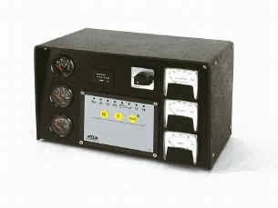
16 DEEP SEA ELECTRONICS PLC 703 Auto Start Issue 5 USA 13/06/02 DESCRIPTION The 703 is an engine auto start and protection module. It utilizes advanced surface mount construction techniques to provide a compact, yet highly specified module. Operation is via three pushbuttons mounted on the front panel with STOP, MANUAL and AUTO positions. OPERATION Stop mode - This is used to stop the engine when it is running and to cancel Auto mode. It is also used to reset any Shutdown Alarm conditions. Manual mode - This mode is used to manually start and run the engine, which can be stopped by pressing the Stop button. Auto mode - This selects the automatic mode of operation, in which the module will await the remote start signal. Once received, the module will initiate its preconfigured Start Sequence, observing the start delay timer before starting the engine. When the remote start signal is removed, the module will initiate its preconfigured Stopping Sequence. The module monitors the engine and provides the following functions: Automatic Start with 3 attempts and Automatic Crank Disconnect - with adjustable Start and Stop Timers and Fail to Start indication. Configurable Pre-heat and Energize to Stop functions. Low Oil Pressure and High Engine Temperature Shutdown. Overspeed and Underspeed (frequency) protection. Charge Fail Alarm Two fully configurable auxiliary inputs. All alarms are indicated by high visibility red LED s. The module s microprocessor provides a comprehensive list of timers and configurable functions. Parameter settings can be adjusted using the front panel pushbuttons once in Configuration Mode. Access to the settings is via a small Configuration Switch on the rear of the module (see figs. 1 and 2), and enables changes to be made in the field. Selection of the Configuration Mode is indicated by rapid flashing of the Auto LED. The module is designed with DSE s proven experience and uses modern construction to provide a high level of reliability and suitability for the intended operating environment. Issues such as environmental compliance and EMC have been carefully engineered into the design. Advanced features such as protected solid state outputs mean that there are no moving parts or contacts to burn-out. FEATURES Micro-processor based design Automatic Engine Starting and Stopping Automatic Shutdown on fault condition Configurable via front panel Simple pushbutton controlled operation Configurable Digital Inputs Configurable Solid State Outputs Configurable Timer Settings Solid State Fuel and Crank outputs External Remote Start input LED Alarm indication Start Delay Timer Stop Delay Timer Energize to Stop timer Pre-heat Timer Over Speed Shutdown Optional Underspeed Protection Low Oil Pressure Shutdown High Engine Temp Shutdown Optional Crank Disconnect from Oil Pressure The 700 series modules have been designed for front panel mounting. The module is fitted into the cut-out, and screw holes are provided for secure fixing. SPECIFICATION DC Supply: 8 to 35 V Continuous. Cranking Dropouts: Able to survive 0 V for 50 ms, providing supply was at least 10 V before dropout and supply recovers to 5V. This is achieved without the need for internal batteries. Max. Current: Operating 50mA Standby 10mA Alternator Input Range: 75(ph-N) to 277(ph-N) 3 Phase 4wire AC (+20%) Alternator Input Frequency: Hz at rated engine speed (Minimum: 75V AC Ph-N) (Crank Disconnect from 15V 20 Hz) Overspeed +14% (+24% overshoot) Underspeed 20% Start Output: 1.2 Amp DC at supply voltage. Fuel Output: 1.2 Amp DC at supply voltage. Auxiliary Outputs: 1.2 Amp DC at supply voltage. Dimensions: 125 X 165 X 28 mm Charge Fail: 12V = 8V CF 24V = 16V CF Operating Temperature Range: -30 to +70 C Compliant with BS EN Low Voltage Directive Compliant with BS EN EMC Directive Compliant with BS EN EMC Directive Deep Sea Electronics reserve the right to change specification without notice.
17 109 CONFIGURATION Configuration Mode is selected by operation of a small switch on the rear, left-hand edge of the PCB. This is partially hidden to prevent accidental operation. See figs 1 and 2 Fig. 1 Normal Configuration Once Configuration Mode is selected, the Auto LED will commence rapid flashing. When in Configuration Mode all normal operation is suspended. The Stop pushbutton can be used to select the LED code that corresponds to the required function. The 5 left hand LED s will form the code The Manual pushbutton will allow the user to change the function parameters. The 3 right-hand LED s inform the user of the current value for the chosen function. When the required parameters are displayed, pressing the Auto button will save the new setting. The process is repeated for each function change. When configuration is complete, the Configuration Mode Selector Switch should be returned to the Normal position. A key to all configuration options is provided (refer to Installation Instructions supplied with module) Fig. 2 Diagram of reverse side of Panel Cut-out: 149 x Fig. 3 Dimensions (mm) F 2A TYPICAL CONNECTIONS Fuel o/p SSO Start o/p SSO Auxiliary Outputs SSO SSO Auxiliary Alarm Inputs F2A F + Battery Fuel Starter motor Crank Charge alt SSO = Solid state outputs = External 'Automotive' or 'Plug-in' type relays Deep Sea Electronics plc Highfield House, Hunmanby Industrial Estate, North Yorkshire, YO14 0PH, England Tel: +44 (0) Fax: +44 (0) sales@deepseaplc.com
18
19
20
DEEP SEA ELECTRONICS PLC
 COMPLEX SOLUTIONS MADE SIMPLE DEEP SEA ELECTRONICS PLC DSE704 AUTOSTART CONTROL MODULE OPERATING MANUAL 057-042 704 Operating Instructions Issue 2.1 18/06/2007 11:27:00 JR - 1 - Deep Sea Electronics Plc
702 AUTOMATIC START MODULE OPERATING INSTRUCTIONS
 702 AUTOMATIC START MODULE OPERATING INSTRUCTIONS > TABLE OF CONTENTS 1 DESCRIPTION OF OPERATION... 4 1.1 MANUAL MODE OPERATION... 4 1.2 AUTOMATIC MODE OF OPERATION...
DEEP SEA ELECTRONICS PLC
 COMPLEX SOLUTIONS MADE SIMPLE. DEEP SEA ELECTRONICS PLC DSE4120 AUTO MAINS FAILURE MODULE OPERATING MANUAL Deep Sea Electronics Plc Highfield House Hunmanby North Yorkshire YO14 0PH ENGLAND Sales Tel:
DEEP SEA ELECTRONICS PLC
 COMPLEX SOLUTIONS MADE SIMPLE. DEEP SEA ELECTRONICS PLC DSE710 AUTOSTART CONTROL MODULE OPERATING MANUAL Deep Sea Electronics Plc Highfield House Hunmanby North Yorkshire YO14 0PH ENGLAND Sales Tel: +44
DEEP SEA ELECTRONICS PLC
 COMPLEX SOLUTIONS MADE SIMPLE DEEP SEA ELECTRONICS PLC DSE720 AUTOSTART CONTROL MODULE OPERATING MANUAL http://bestgenerator.spb.ru/?page_id=6765 Deep Sea Electronics Plc Highfield House Hunmanby North
Deep Sea Electronics Plc
 Deep Sea Electronics Plc 5120 AUTOMATIC MAINS FAILURE MODULE OPERATING MANUAL Author: Anthony Manton Deep Sea Electronics Plc Highfield House Hunmanby North Yorkshire YO14 0PH England Tel: +44 (0) 1723
MODEL 520 REMOTE START ENGINE MANAGEMENT SYSTEM
 MODEL 520 REMOTE START ENGINE MANAGEMENT SYSTEM DSE 520 ISSUE 4 4/4/02 MR 1 TABLE OF CONTENTS Section Page INTRODUCTION... 4 CLARIFICATION OF NOTATION USED WITHIN THIS PUBLICATION.... 4 1. OPERATION...
DEEP SEA ELECTRONICS PLC
 COMPLEX SOLUTIONS MADE SIMPLE. DEEP SEA ELECTRONICS PLC DSE5110 AUTOSTART CONTROL MODULE OPERATING MANUAL Deep Sea Electronics Plc Highfield House Hunmanby North Yorkshire YO14 0PH ENGLAND Sales Tel: +44
5220 AUTOMATIC MAINS FAILURE MODULE OPERATING MANUAL
 5220 AUTOMATIC MAINS FAILURE MODULE OPERATING MANUAL > Section DSE Model 5220 Automatic Mains Failure & Instrumentation System Operators Manual TABLE OF CONTENTS
DSEULTRA DSE6000 Quick Start Guide Document Number
 n DSEULTRA DSE6000 Quick Start Guide Document Number 057-102 Author : John Ruddock Deep Sea Electronics Plc Highfield House Hunmanby North Yorkshire YO14 0PH ENGLAND Sales Tel: +44 (0) 1723 890099 Sales
DEEP SEA ELECTRONICS PLC
 COMPLEX SOLUTIONS MADE SIMPLE. DEEP SEA ELECTRONICS PLC DSE5220 AUTO MAINS FAILURE MODULE OPERATING MANUAL Deep Sea Electronics Plc Highfield House Hunmanby North Yorkshire YO14 0PH ENGLAND Sales Tel:
Deep Sea Electronics Plc
 Deep Sea Electronics Plc 550 Operators Manual Author Miles Revell Deep Sea Electronics Plc Highfield House Hunmanby Industrial Estate North Yorkshire YO14 0PH ENGLAND Tel +44 (0) 1723 890099 Fax +44 (0)
DEEP SEA ELECTRONICS PLC DSE3210 Configuration Suite Software Manual
 DEEP SEA ELECTRONICS PLC DSE3210 Configuration Suite Software Manual Document Number 057-152 Author : Paul Gibbons DSE3210 Configuration Suite Software Manual Issue 1 DSE3210 Configuration Suite Software
Deep Sea Electronics Plc
 Deep Sea Electronics Plc 5520 Operators Manual Author Tony Manton Deep Sea Electronics Plc Highfield House Hunmanby Industrial Estate North Yorkshire YO14 0PH ENGLAND Tel +44 (0) 1723 890099 Fax +44 (0)
DKG-114 MANUAL AND REMOTE START UNIT
 DKG-114 MANUAL AND REMOTE START UNIT FEATURES Both manual and remote controlled engine starting and stopping, Automatic shutdown on fault condition, Optional cooldown cycle on remote start operation, Optional
HGM72 Automatic Generator Module OPERATING MANUAL Smartgen Electronic
 HGM72 Automatic Generator Module OPERATING MANUAL Smartgen Electronic CONTENT 1 SUMMARY... 4 2 FEATURES... 4 3 SPECIFICATION... 4 4 DISPLAY SYMBOL AND OPERATION... 5 5 ALARM... 7 6 PARAMETERS TABLE (ONLY
Flight Systems. Replacement for KASSEC DESCRIPTION
 DESCRIPTION The is a universal generator controller that will start, stop, and provide engine protection for most generators. Universal replacement for both the 90353 and 90354 KASSEC Compatible with most
GCU-10. Automatic Engine Control Unit Operators Manual
 GCU-10 Automatic Engine Control Unit Operators Manual KUTAI ELECTRONICS INDUSTRY CO., LTD. TEL : +886-7-8121771 FAX : +886-7-8121775 Website : www.kutai.com.tw Headquarters : No.3, Lane 201, Chien Fu St.,
HGM72 Automatic Generator Module OPERATING MANUAL Smartgen Electronic
 HGM72 Automatic Generator Module OPERATING MANUAL Smartgen Electronic Smartgen Electronic Equipment Co., Ltd No.28 Jinsuo Road Zhengzhou Henan Province P.R.China Tel: 0086-371-67988888/67981888 0086-371-67991553/67992951/67992952
GENSET CONTROL MODULE A121A / A241A
 Technical Data Sheet GENSET CONTROL MODULE A121A / A241A Features: Models for both 12V and 24V systems. One model for both spark ignition and diesel engines. 4-alarm light outputs with lamp-test provisions.
PSM72H Push-Button Start Module
 Capricorn Controls DA02PSM72H1-2 Data & Application Note Page 1 of 6 PSM72H Push-Button Start Module Genset Controls - Timers/Monitors/Trips - Battery Charging Spares & Accessories - Custom Products Ultra
DEEP SEA ELECTRONICS PLC DSE3210 CONTROLLER OPERATORS MANUAL
 DEEP SEA ELECTRONICS PLC DSE3210 CONTROLLER OPERATORS MANUAL Document number 057-153 Author: Allan Jones DSE3210 Operators Manual Issue 1 http://bestgenerator.spb.ru/?page_id=6765 Deep Sea Electronics
REVISED ATM72 Auto Transfer Module
 Capricorn Controls DA01ATM1-1 Data & Application Note Page 1 of 8 REVISED - - - ATM72 Auto Transfer Module Genset Controls - Timers - Monitors - Trips - Battery Charging - Spares & Accessories - Custom
MD10. Engine Controller. Installation and User Manual for the MD10 Engine Controller. Full Version
 MD10 Engine Controller Installation and User Manual for the MD10 Engine Controller. Full Version File: MartinMD10rev1.4.doc May 16, 2002 2 READ MANUAL BEFORE INSTALLING UNIT Receipt of shipment and warranty
HSC940 Genset Controller CONTENTS 1 OVERVIEW PERFORMANCE AND CHARACTERISTICS SPECIFICATION OPERATION KEY FUNCTIONS...
 CONTENTS 1 OVERVIEW... 4 2 PERFORMANCE AND CHARACTERISTICS... 5 3 SPECIFICATION... 7 4 OPERATION... 8 4.1 KEY FUNCTIONS... 8 4.2 INDICATOR LIGHT... 9 4.3 AUTO START/STOP OPERATION... 10 4.4 MANUAL START/STOP
GENSET CONTROL MODULE LEVEL 0 A120A. User selectable time delays for engine start and engine stop (cool down).
.") Technical Data Sheet GENSET CONTROL MODULE LEVEL 0 A120A Features: One model for both spark ignition and diesel engines. 4-alarm light outputs with automatic lamp-test provision. Overspeed adjustment not
Technical Data Sheet GENSET CONTROL MODULE LEVEL 0 A120A Features: One model for both spark ignition and diesel engines. 4-alarm light outputs with automatic lamp-test provision. Overspeed adjustment not
GENSET CONTROL MODULE LEVEL 1 A121CM / A241CM. Special logic to re-establish cranking following a false start.
 Technical Data Sheet GENSET CONTROL MODULE LEVEL 1 A121CM / A241CM Features: Models for both 12V and 24V systems. One model for both spark ignition and diesel engines. 5-alarm light outputs with lamp-test
GENSET CONTROL MODULE A121H / A241H. User selectable time delays for engine start and engine stop (cool down).
.") Technical Data Sheet GENSET CONTROL MODULE A121H / A241H Features: Models for both 12V and 24V systems. One model for both spark ignition and diesel engines. 4-alarm light outputs with lamp-test provisions.
Technical Data Sheet GENSET CONTROL MODULE A121H / A241H Features: Models for both 12V and 24V systems. One model for both spark ignition and diesel engines. 4-alarm light outputs with lamp-test provisions.
DEEP SEA ELECTRONICS
 DEEP SEA ELECTRONICS DSEE100 Configuration Suite PC Software Manual Document Number: 057-267 Author: Bedig Boghossian 057-267 ISSUE: 1 DSEE100 Configuration Suite PC Software Manual DEEP SEA ELECTRONICS
DEEP SEA ELECTRONICS
 DEEP SEA ELECTRONICS DSE6010 MKII / DSE6020 MKII Configuration Suite PC Software Manual Document Number: 057-223 Author: Fady Atallah DSE6010 MKII / DSE6020 MKII Configuration Suite PC Software Manual
DEEP SEA ELECTRONICS DSE7110 MKII / DSE7120 MKII Configuration Suite PC Software Manual
 DEEP SEA ELECTRONICS DSE7110 MKII / DSE7120 MKII Configuration Suite PC Software Manual Document Number 057-185 Author: Fady Atallah DSE7110 MKII / DSE7120 MKII Configuration Suite PC Software Manual DSE7110
HGM1750 Genset Security Module USER MANUAL Smartgen Technology
 HGM1750 Genset Security Module USER MANUAL Smartgen Technology CONTENT 1. SUMMARY... 4 2. PERFORMANCE AND CHARACTERISTICS... 5 3. SPECIFICATION... 7 4. OPERATION... 8 5. PROTECTION... 9 6. PARAMETER RANGE
HGM6410/6420. Automatic Generator Module. With J1939 Interface OPERATING MANUAL. Smartgen Electronics
 HGM6410/6420 Automatic Generator Module With J1939 Interface OPERATING MANUAL Smartgen Electronics Smartgen Electronic Equipment Co,.Ltd No.12 Dongqing Street Zhengzhou Henan Province P.R.China Tel : (0086)-371-67992951
4.2 Component Identification
 Digital Control Panels Deep Sea Electronics 5220 4.1 General 4.2 Component Identification 4.3 The YML5220 Controller 4.4 Description of Controls 4.5 Navigation 4.5.1 General Navigation 4.5.2 The Event
USER MANUAL ZHENGZHOU SMARTGEN TECHNOLOGY CO.,LTD
 HGM400 Series Genset Controller (HGM410/HGM420) USER MANUAL ZHENGZHOU SMARTGEN TECHNOLOGY CO.,LTD CONTENTS 1 OVERVIEW... 5 2 PERFORMANCE AND CHARACTERISTICS... 6 3 SPECIFICATION... 8 4 OPERATION... 9 4.1
HGM6410/6420 AUTOMATIC GENERATOR MODULE WITH J1939 INTERFACE SOFTWARE MANUAL
 HGM6410/6420 AUTOMATIC GENERATOR MODULE WITH J1939 INTERFACE SOFTWARE MANUAL SMARTGEN ELECTRONICS Smartgen Electronic Equipment Co., Ltd No.12 Dongqing Street Zhengzhou Henan Province P.R.China Tel : (0086)-371-67992951
Manual and Remote Start Unit with Key Switch, 72x72 DIN Size
 Manual and Remote Start Unit with Key Switch, x DI Size FAILED TO ~~~ ~ ~ STOP 0 I Hz./ EAOM - 36 SPEED FAILURE CHARGIG FAIL Features Designed For Generator, Pump & Fire Pump Applications Remote start
DEEP SEA ELECTRONICS PLC DSEE100 Operator Manual
 DEEP SEA ELECTRONICS PLC DSEE100 Operator Manual Document Number: 057-273 Author: Fady Atallah 057-273 ISSUE: 2 DSEE100 Operator Manual Deep Sea Electronics Plc Highfield House Hunmanby North Yorkshire
HGM501 Gen-set Controller USER MANUAL. Smartgen Technology
 HGM501 Gen-set Controller USER MANUAL Smartgen Technology Contents 1. 2. 3. 4. 5. 6. 7. 8. 9. OVERVIEW... 4 PERFORMANCE AND CHARACTERISTICS... 4 TECHNICAL DATA... 5 OPERATION... 6 4.1. BUTTON DESCRIPTION...
ECU-02 Ver2.1 Automatic Engine Control Unit Operators Manual
 ECU-02 Ver2.1 Automatic Engine Control Unit Operators Manual Headquarters : No.3, Lane 201, Chien Fu St., Chyan Jenn Dist., Kaohsiung, TAIWAN Tel : + 886-7-8121771 Fax : + 886-7-8121775 URL : http://www.kutai.com.tw
HGM1780 AUTOMATIC GENERATOR MODULE CONTENT 1. SUMMARY PERFORMANCE AND CHARACTERISTICS SPECIFICATION OPERATION...
 CONTENT 1. SUMMARY...4 2. PERFORMANCE AND CHARACTERISTICS...4 3. SPECIFICATION...5 4. OPERATION...6 4.1. DISPLAY PANEL...6 4.2. LCD ICON INSTRUCTION...7 4.3. DISPLAY INSTRUCTIONS...7 4.4. DISPLAY DESCRIPTION...8
HGM1780. Automatic Genset Controller USER MANUAL. Smartgen Technology
 HGM1780 Automatic Genset Controller USER MANUAL Smartgen Technology Smartgen Technology Co., Ltd No. 28 Jinsuo Road Zhengzhou Henan Province P. R. China Tel: 0086-371-67988888/67981888 0086-371-67991553/67992951
HGM1770 Automatic Generator Control Module OPERATING MANUAL Smartgen Electronic
 HGM1770 Automatic Generator Control Module OPERATING MANUAL Smartgen Electronic CONTENT 1. SUMMARY... 4 2. PERFORMANCE AND CHARACTERISTICS... 4 3. SPECIFICATIONS... 5 4. OPERATION... 6 5. PROTECTION...
VC-4820 Programmable DC-DC Converter with Battery Charger function USER'S MANUAL
 1. INTRODUCTION VC-4820 Programmable DC-DC Converter with Battery Charger function USER'S MANUAL This MCU controlled Step Down DC-DC Converter has a digitally adjustable output in 0.2V increments. This
HGM6320T AUTOMATIC GENERATOR CONTROLLER USER MANUAL
 HGM6320T AUTOMATIC GENERATOR CONTROLLER USER MANUAL Smartgen Technology Smartgen Technology Co., Ltd No. 28 Jinsuo Road Zhengzhou Henan Province P. R. China Tel: 0086-371-67988888/67981888 0086-371-67991553/67992951/67992952
HGM6320T AUTOMATIC GENERATOR CONTROLLER USER MANUAL
 HGM6320T AUTOMATIC GENERATOR CONTROLLER USER MANUAL Smartgen Technology CONTENT 1 SUMMARY... 4 2 PERFORMANCE AND CHARACTERISTICS... 4 3 SPECIFICATION... 5 4 OPERATION... 6 4.1 LCD DISPLAY... 6 4.2 KEY
AUTOSTART 705S V1.00 AUTOSTART 710S / 720S / 730S V1.04 Programming Reference and Check Sheets
 The Generator Controls Division of Frank W. Murphy AUTOSTART 705S V1.00 AUTOSTART 710S / 720S / 730S V1.04 Programming Reference and Check Sheets MODEX AUTOMATION FRANK W. MURPHY LTD. Church Road Laverstock
HGM7100N SERIES (HGM7110N/7120N) GENSET CONTROLLER USER MANUAL
 GENSET CONTROLLER USER MANUAL") HGM7100N SERIES (HGM7110N/7120N) GENSET CONTROLLER USER MANUAL SMARTGEN (ZHENGZHOU) TECHNOLOGY CO., LTD. Chinese trademark English trademark SmartGen make your generator smart SmartGen Technology Co.,
HGM7100N SERIES (HGM7110N/7120N) GENSET CONTROLLER USER MANUAL SMARTGEN (ZHENGZHOU) TECHNOLOGY CO., LTD. Chinese trademark English trademark SmartGen make your generator smart SmartGen Technology Co.,
Energy Division
 Energy Division http://energy.tycoelectronics.com Installation and Operating Manual GEN-TRANS Automatic Generator Transfer Switch Controller with Metering Tyco Electronics UK Limited Crompton Instruments
SDM72 Start on Demand Modules
 Capricorn Controls DA04SDM72-2 Revised Design Page 1 of 6 SDM72 Start on Demand Modules Genset Controls - Timers - Monitors - Trips - Battery Charging - Spares & Accessories - Custom Products Application
EPM72 Engine Protection Module
 Capricorn Controls DA01EPM1-1 Data & Application Note Page 1 of 8 EPM2 Engine Protection Module Genset Controls - Timers - Monitors - Trips - Battery Charging - Spares & Accessories - Custom Products All
GSC300 Auto Start Engine Controller
 GSC300 Auto Start Engine Controller Revision 2.12 Installation and User Manual for the GSC300 Auto Start Engine Controller File: MAN-0039 R2.12, GSC300 User Manual.doc June 2014 2 of 28 Thank You For Purchasing
STANDARD OWNER S MANUAL
 WILLIE 1.0 STANDARD OWNER S MANUAL OPERATION, MAINTENANCE, & TROUBLESHOOTING STANDARD INSTRUCTIONS FOR ALL SYSTEMS DSE 3100 4/28/2011 Willis Power Systems 2950 N Martin Springfield, MO 65803 417.831.2520
HGM6000K Series Automatic Generator Module OPERATING MANUAL Smartgen Electronic
 HGM6000K Series Automatic Generator Module OPERATING MANUAL Smartgen Electronic CONTENT 1 SUMMARY... 4 2 PERFORMANCE AND CHARACTERISTICS... 4 3 SPECIFICATION... 6 4 OPERATION... 6 4.1 KEY FUNCTION... 6
 8803214-8803999 DIODE BOARD The diode board is located inside the lower control box. D15 D8 D7 D14 D5 D13 ART_2181 J1 14 8 D9 D10 7 1 R2 R1 R3 R4 TB1 8601 D11 D3 D12 D4 D1 D2 J1 Plug Pin Identification
 DIODE BOARD The diode board is located inside the lower control box. D15 D8 D7 D14 D5 D13 ART_2181 J1 14 8 D9 D10 7 1 R2 R1 R3 R4 TB1 8601 D11 D3 D12 D4 D1 D2 J1 Plug Pin Identification PIN # WIRE # SIGNAL
ENGINE PROTECTION BOARD PDM1
 ENGINE PROTECTION BOARD REFERENCE MANUAL. Standard of reference: IEC/EN 60255-6 IEC/EN 61000-4-2 IEC/EN 61000-4-3 IEC/EN 61000-4-4, IEC/EN 61000-4-5 IEC/EN 61000-4-6 IEC/EN 55011 IEC/EN 60028-2-61 IEC/EN
Dycon D1532SM. EN50131/PD6662 Grade 3, 12V 2A Power Supply. Technical Description Installation and Operating Manual DYCON POWER SOLUTIONS LTD
 Dycon D1532SM EN50131/PD6662 Grade 3, 12V 2A Power Supply Technical Description Installation and Operating Manual DYCON POWER SOLUTIONS LTD Tel: +44 (0)1443 471 900 Unit A Cwm Cynon Business Park Mountain
ES52 Auto Start Engine Controller Installation and User Manual for the ES52 Auto Start Engine Controller.
 ES52 Auto Start Engine Controller Installation and User Manual for the ES52 Auto Start Engine Controller. Full Version File: ES52rev2.63.doc October 24, 2006 2 Thank You For Purchasing This DynaGen Product
ICON 2 1. FEATURES AND CHARACTEIRICS
 ICON 2 1. FEATURES AND CHARACTEIRICS High end Micro-controller(DSP) technology Wide range of auxiliary supply: 7V to 45Vdc. Low power Consumption : 200 ma @ 12 V DC. Alphanumeric 16X4 or 16X2 LCD display
InteliCharger V 20A Intelligent Automatic Battery Charger
 InteliCharger InteliCharger 500 24V 20A Intelligent Automatic Battery Charger September 2012 Reference Guide TABLE OF CONTENTS 1 Document information... 2 2 EQUIPMENT RATING... 3 3 ENVIRONMENT... 3 4 PROTECTION...
KD LV Motor Protection Relay
 1. Protection Features KD LV Motor Protection Relay Overload (for both cyclic and sustained overload conditions) Locked rotor by vectorial stall Running stall / jam Single phasing / Unbalance Earth leakage
20 KW / 25 KVA LIQUID COOLED POWERED by
 20 KW / 25 KVA LIQUID COOLED POWERED by MODEL Triton Power is a world leader in the design, manufacture of stationary, mobile, natural gas, rental generators and Power Modules from 10 to 2000 kw. Through
AA4006 Speed Sensitive Trip Unit. User Manual
 AA4006 Speed Sensitive Trip Unit User Manual Software Version 2.00 Issued 01/2005 Don Controls Limited Westfield Industrial Estate Kirk Lane, Yeadon Leeds, LS19 7LX Telephone: +44 (0)845 1304946 Fax: +44
DKG-317 MANUAL AND REMOTE START UNIT
 Tel: +54-11-4629-600 Fax:+54-11-4627-3500 http://www.cramelectro.com DKG-317 MANUAL AND REMOTE START UNIT FEATURES Manual starting and stopping Engine control Generator protection Built in alarms and warnings
Starting System DS-102 Series 200. Elmatik AS P.O.Box 309 NO-3471, Slemmestad T F
 Starting System DS-102 Series 200 Elmatik AS P.O.Box 309 NO-3471, Slemmestad T - +47 31 28 37 83 F - +47 31 28 37 93 www.elmatik.no post@elmatik.no CONTENT 1. INTRODUCTION 3 2. TECHNICAL SPECIFICATIONS
HGM6400 Automatic Genset Controller (With J1939 Interface) USER MANUAL Smartgen Technology
 USER MANUAL Smartgen Technology") HGM6400 Automatic Genset Controller (With J1939 Interface) USER MANUAL Smartgen Technology Chinese trademark English trademark Smartgen make your generator smart Smartgen Technology Co., Ltd No. 28 Jinsuo
HGM6400 Automatic Genset Controller (With J1939 Interface) USER MANUAL Smartgen Technology Chinese trademark English trademark Smartgen make your generator smart Smartgen Technology Co., Ltd No. 28 Jinsuo
DEEP SEA ELECTRONICS PLC DSEL401 MKII Operator Manual
 DEEP SEA ELECTRONICS PLC DSEL401 MKII Operator Manual Document Number: 057-221 Author: Ashley Senior 057-221 ISSUE: 2 DSEL401 MKII Operator Manual DEEP SEA ELECTRONICS PLC Highfield House Hunmanby North
GSC300 Auto Start Engine Controller
 GSC300 Auto Start Engine Controller Revision 2.9 Installation and User Manual for the GSC300 Auto Start Engine Controller File: MAN-0039 R2.9, GSC300 User Manual.doc May 2011 2 of 29 Thank You For Purchasing
GSC300. Auto Start Engine Controller. Installation and User Manual for the GSC300 Auto Start Engine Controller. Full Version
 GSC300 Auto Start Engine Controller Installation and User Manual for the GSC300 Auto Start Engine Controller Full Version File: GSC300rev2.4.doc Dec. 08, 2005 2 Thank You For Purchasing This DynaGen Product
1. AC VOLTS: Displays generator output in voltage. 2. AC FREQUENCY: Displays the speed of the generator set in Hertz.
 1. AC VOLTS: Displays generator output in voltage. 2. AC FREQUENCY: Displays the speed of the generator set in Hertz. 3. AMMETER/PERCENT OF LOAD: Displays the load on the generator in amps or in percentage.
Dycon D2430 EN54-4 Fire Alarm Power Supply Series
 Dycon D2430 EN54-4 Fire Alarm Power Supply Series Technical Description Installation and Operating Manual Construction Product Regulation 0359-CPR-00434 Page 1 of 14 Contents 1. General... 3 1.1 Product
Ag Features. Multi-Stage Charging. Solar Panel or DC Input. Maximum Power Point Tracking (MPPT) Very Low Power Consumption
 Very Low Power Consumption") Datasheet Ag103 Intelligent Sealed Lead Acid Solar Battery Charger Module Pb 1 Features Multi-Stage Charging Solar Panel or DC Input Maximum Power Point Tracking (MPPT) Very Low Power Consumption Wide
Datasheet Ag103 Intelligent Sealed Lead Acid Solar Battery Charger Module Pb 1 Features Multi-Stage Charging Solar Panel or DC Input Maximum Power Point Tracking (MPPT) Very Low Power Consumption Wide
HGM6310D/6320D AUTOMATIC GENERATOR MODULE USER MANUAL
 HGM6310D/6320D AUTOMATIC GENERATOR MODULE USER MANUAL SMARTGEN ELECTRONIC CONTENT 1 SUMMARY... 4 2 PERFORMANCE AND CHARACTERISTICS... 4 3 SPECIFICATION... 6 4 OPERATION... 7 4.1 KEY FUNCTION... 7 4.2 AUTOMATIC
DEEP SEA ELECTRONICS PLC DSE9000 SERIES BATTERY CHARGER OPERATOR MANUAL
 DEEP SEA ELECTRONICS PLC DSE9000 SERIES BATTERY CHARGER OPERATOR MANUAL Document Number: 057-085 Author: Ashley Senior DSE9000 Series Battery Charger Operator Manual ISSUE 13 DSE9000 Series Battery Charger
DKG-215 MANUAL AND REMOTE START UNIT
 DKG-215 MANUAL AND REMOTE START UNIT FEATURES Manual and remote starting and stopping Zero power consumption at rest Engine control mode available Generator protection Built in alarms and warnings 1 phase
MB A 12V/24V DC PROGRAMMABLE DUAL BATTERY ISOLATOR
 MB-3688 120A 12V/24V DC PROGRAMMABLE DUAL BATTERY ISOLATOR User Manual Warning and Precautions MB-3688 is built with corrosion resistant material and the main electronic assembly is well sealed inside
Controls and Instruments
 CHAPTER 9 Controls and Instruments A complex set of controls and instruments monitors the operation of an electric generator set. Equipment operators must understand what these controls and instruments
DEEP SEA ELECTRONICS PLC DSE7450 Configuration PC Suite Software Manual. Document Number:
 DEEP SEA ELECTRONICS PLC DSE7450 Configuration PC Suite Software Manual Document Number: 057-169 Author: Paul Gibbons DSE7450 Configuration Suite PC Software Manual ISSUE 3 DEEP SEA ELECTRONICS PLC Highfield
The measurements module provides the following engine features information:
 1. INTRODUCTION The CEM6 control board is a monitoring network signal and monitoring and control generator feeding device. The device consists of 2 different modules: - Visualization module. The visualization
INSTALLATION GUIDE Table of Contents
 CT-3100 Automatic transmission remote engine starter systems. What s included..2 INSTALLATION GUIDE Table of Contents Door lock toggle mode..... 4 Notice...2 Installation points to remember. 2 Features..2
DEEP SEA ELECTRONICS PLC DSE6010 MKII & DSE6020 MKII Operator Manual
 DEEP SEA ELECTRONICS PLC DSE6010 MKII & DSE6020 MKII Operator Manual Document Number: 057-230 Author: Mark Graham 057-230 IS 057-230 ISSUE: 1 DEEP SEA ELECTRONICS PLC Highfield House Hunmanby North Yorkshire
ADD-ON REMOTE STARTER TO AFTERMARKET SYSTEM
 MEGATRONIX RS 110 ADD-ON REMOTE STARTER TO AFTERMARKET SYSTEM Installation and Operation Manual MEGATRONIX CHATSWORTH, CA U.S.A. RS110 ADD-ON REMOTE CAR STARTER For Vehicles Equipped With Automatic Transmission
VC-30 / VC-40 Programmable DC-DC Converter with Battery Charger function USER'S MANUAL
 1. INTRODUCTION VC-30 / VC-40 Programmable DC-DC Converter with Battery Charger function USER'S MANUAL This MCU controlled Step Down 24V to 12V DC-DC Converter has a programmable 12.0 to 15.0V output in
100 KW(NG) / 100 KW(LP) LIQUID COOLED POWERED by
 / 100 KW(LP) LIQUID COOLED POWERED by") 100 KW(NG) / 100 KW(LP) LIQUID COOLED POWERED by MODEL Triton Power is a world leader in the design, manufacture of stationary, mobile, natural gas, rental generators and Power Modules from 10 to 2000
100 KW(NG) / 100 KW(LP) LIQUID COOLED POWERED by MODEL Triton Power is a world leader in the design, manufacture of stationary, mobile, natural gas, rental generators and Power Modules from 10 to 2000
DKG-207 AUTOMATIC MAINS FAILURE AND REMOTE START UNIT
 DKG-207 AUTOMATIC MAINS FAILURE AND REMOTE START UNIT FEATURES Automatic mains failure, Engine control, Gas engine support, Generator protection, Built in alarms and warnings, 3 phase mains voltage inputs
Cascade CD101 Auto-Start Controller. Installation and Operations Manual Sections 40 & 75
 Cascade CD101 Auto-Start Controller Installation and Operations Manual 00-02-0594 2018-02-15 Sections 40 & 75 In order to consistently bring you the highest quality, full featured products, we reserve
Timer Relays - Fixed & Adjustable
 Solid State Solid State relays are suitable across all applications where reliability is paramount. Unlike conventional relays, Solid State relays use electronics in place of traditional contacts, allowing
AUTOMATIC STAND-BY AND PEAK-LOAD CONTROL
 KUHSE Operating Instructions Control Unit for Gen. Power Sets AUTOMATIC STAND-BY AND PEAK-LOAD CONTROL Type: KEA 071-SPL TA71SXXE.01 July 1996 (REPLACES 1994 EDITION) GENERAL DESCRIPTION AND APPLICATION
DEEP SEA ELECTRONICS PLC DSE6610 & DSE6620 Operator Manual
 DEEP SEA ELECTRONICS PLC DSE6610 & DSE6620 Operator Manual Document Number: 057-190 Author: Ashley Senior DSE6610 & DSE6620 Operator Manual ISSUE 1 DSE6610 & DSE6620 Operator Manual DEEP SEA ELECTRONICS
Burden Fuse Rating Resistor SAF / SAK6 1NM 10mm M8 12NM SAF / SAK10 2NM 16mm M8 12NM
 Contents Section Page 1.0 Introduction 1 2.0 Specification 1-4 3.0 Installation 5-8 4.0 Programming 9-10 5.0 Menus 10-12 6.0 Fault Finding/Diagnostics 12-13 7.0 Communication 13 8.0 Setting Up 13-16 1.0
HGM6000K Series Automatic Generator Module USER MANUAL Smartgen Technology
 HGM6000K Series Automatic Generator Module USER MANUAL Smartgen Technology Chinese trademark English trademark Smartgen make your generator smart Smartgen Technology Co., Ltd. No. 28 Jinsuo Road Zhengzhou
ES52. Auto Start Engine Controller. Full Version. Installation and User Manual for the ES52 Auto Start Engine Controller.
 ES52 Auto Start Engine Controller Installation and User Manual for the ES52 Auto Start Engine Controller. Full Version File: MAN-0001 R4.0, ES52 User Manual.doc Date: August 2017 Thank You For Purchasing
Installation and Maintenance Instructions. World Leader in Modular Torque Limiters. PTM-4 Load Monitor
 World Leader in Modular Torque Limiters Installation and Maintenance Instructions PTM-4 Load Monitor 1304 Twin Oaks Street Wichita Falls, Texas 76302 (940) 723-7800 Fax: (940) 723-7888 E-mail: sales@brunelcorp.com
Elmdene International Ltd
 1 Elmdene International Ltd Tel: +44(0)23 9269 6638 3 Keel Close, Interchange Park, Fax: +44(0)23 9266 0483 Portsmouth, Hampshire, PO3 5QD, UK Web: www.elmdene.co.uk 13.8Vdc Switch Mode Power Supply GEN3-08-y
USER MANUAL FOR GC500 GENSET CONTROLLER SEDEMAC ABSTRACT
 ABSTRACT This manual is intended as an information guide for operating SEDEMAC's GC500 genset controller. USER MANUAL FOR Doc #SED-MAN-GC500-002 Date: 01-Aug-2016 GC500 GENSET CONTROLLER Product Manual
ELECTRICAL SYSTEM RP-7
 ELECTRICAL SYSTEM RP-7 This section of the manual does not include integral electrical components of the engine. Refer to section Engine RP-1 for details. This section of the manual is divided into three
OPERATING INSTRUCTIONS ECON-M
 OPERATING INSTRUCTIONS ECON-M INDEX 1.0 Introduction 2.0 Salient features, Protection & Supervision 3.0 Display/ Front Panel 4.0 Switches Description 5.0 LED Annunciations Description 6.0 Lamp Test 7.0
Auto Mains Failure AMF Controller AE10113
 Auto Mains Failure AMF Controller AE03 Auto Mains Failure DESCRIPTION AMF Controller AE03 is an Automatic Mains Failure controller, which activates the generator during power failure & vice versa. The
DKG-705 AUTOMATIC MAINS FAILURE AND REMOTE START UNIT WITH PARALLEL TO MAINS AND DUAL GENSET PARALLEL FEATURES
 Genset Automation Control Pte Ltd DKG-705 AUTOMATIC MAINS FAILURE AND REMOTE START UNIT WITH PARALLEL TO MAINS AND DUAL GENSET PARALLEL FEATURES FEATURES Automatic mains failure, Remote start operation,